-
Contents
-
Table of Contents
-
Bookmarks
Quick Links
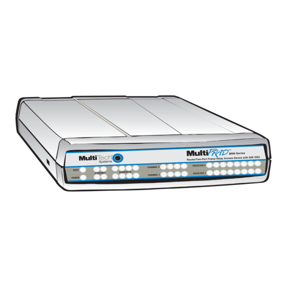
MultiFRAD 200-Series
Models FR220 & FR220/V2
User Guide
Related Manuals for Multitech MultiFRAD FR220
Summary of Contents for Multitech MultiFRAD FR220
-
Page 1
MultiFRAD 200-Series Models FR220 & FR220/V2 User Guide… -
Page 2
Furthermore, Multi-Tech Systems, Inc. reserves the right to revise this publication and to make changes from time to time in the content hereof without obligation of Multi-Tech Systems, Inc. to notify any person or organization of such revisions or changes. -
Page 3: Table Of Contents
Chapter 1 — Introduction and Description Introduction … 6 Related Documentation … 7 Preview of this Guide … 7 Front Panel Description … 8 Back Panel Description … 10 Shunts … 11 Technical Specifications … 12 Chapter 2 — Installation Introduction …
-
Page 4
Changing Channel Parameters (FR220/V2 only) … 58 Interface … 58 Voice/Fax (FR220/V2 only) … 59 Regional (FR220/V2 only) … 60 Changing the Phone Directory Database (FR220/V2 only) … 61 Others Setup … 63 Chapter 5 — Remote Configuration and Management Introduction … 66 Remote Configuration … -
Page 5: Chapter 1 — Introduction And Description
Chapter 1 — Introduction and Description…
-
Page 6: Introduction
To access this free voice and fax communication, all you have to do is connect the FR220/V2 to your telephone equipment and then to your existing frame relay connection. Once configured, the FR220/V2 allows voice and fax to travel down the same path as your traditional data communications.
-
Page 7: Related Documentation
Copies of the following guides are provided on the Manuals disk that ships with each MultiFRAD, and you can always find the latest version of the guide at Multi-Tech’s Web site. At the Multi-Tech Home Page (http://multitech.com), click Support, then Manuals, then MultiFRAD and you will find the guides listed there by title.
-
Page 8: Front Panel Description
MultiFRAD User Guide Front Panel Description The front panel has three groups of LEDs that provide the status of the LAN connection, trunk and data channel activity, and general status of the MultiFRAD. From left to right, the first group of LEDs indicates whether the self test passed or failed and if the power On/Off switch on the back of the MultiFRAD is switched On.
-
Page 9
VOICE/FAX CHANNELS Foreign Exchange Station indicator lights when the voice/fax Channel is configured for FXS operation. Foreign Exchange Office indicator lights when the voice/fax Channel is configured for FXO operation. E&M Ear and Mouth indicator lights when the voice/fax Channel is configured for E&M operation. Fax indicator lights when there is fax traffic on the voice/fax Channel. -
Page 10: Back Panel Description
MultiFRAD User Guide Back Panel Description All the cable connections to the MultiFRAD are made at the back panel. Four categories of signal cables are used on the MultiFRAD: Ethernet, Channels, Command Port, and Trunk (RS232/V.35). The back panel connectors are shown in Figure 1-3 and described in the following groups.
-
Page 11: Shunts
Shunts There are three shunts (Figure 1-4) on the printed circuit board for the trunk and the data Channels. Trunk RS232 Shunt Position Trunk V.35 Shunt Position Channel 1 V.35 Shunt Position Channel 2 V.35 Shunt Position Figure 1-4. Shunts The MultiFRAD has separate shunts for the composite link (or trunk) and both data Channels.
-
Page 12: Technical Specifications
MultiFRAD User Guide Technical Specifications The MultiFRAD conforms to the following specifications: • Provides access to Frame Relay Networks for IP, IPX, bridged LAN traffic, Async and HDLC Sync devices • Trunk and data ports can be configured as either EIA-232 or V.35 •…
-
Page 13: Chapter 2 — Installation
Chapter 2 — Installation…
-
Page 14: Introduction
The battery has an estimated life expectancy of ten years. When the battery starts to weaken, the date and time may be incorrect. If the battery fails, the voice/ fax board must be sent back to Multi-Tech Systems for battery replacement.
-
Page 15: Unpacking Your Multifrad
(Figure 2-1) before proceeding with the installation. If any item appears to be damaged, do not power up the unit; contact Multi-Tech’s Technical Support personnel for advice (Refer to Chapter 6). If no damage is observed, configure the MultiFRAD using the information in the rest of this chapter.
-
Page 16: Cabling Your Multifrad
Note: The E&M, FXS, and Ethernet ports are not designed to be connected to a Public Telecommunication Network. On the FR220/V2 only: if you are connecting your MultiFRAD to a station device; e.g., analog telephone, fax machine, or Key Telephone System (KTS); connect one of the supplied RJ-11 cables to the Voice/Fax Channel 1 FXS connector on the back of the MultiFRAD and the other end to the station device.
-
Page 17
If you are connecting your MultiFRAD to a PBX extension, connect one of the supplied RJ-11 cables to the Voice/Fax Channel 1 FXO connector on the back of the MultiFRAD and the other end to the PBX extension If you are connecting your MultiFRAD to an E&M trunk from a telephone switch, connect one end of an RJ-45 phone cord to the Voice/Fax Channel 1 E&M connector on the back of the MultiFRAD and the other end to the trunk. -
Page 18: E&M Jumper Block Positioning Procedure
E&M Jumper Block Positioning Procedure Each voice/fax channel on the FR220/V2 Only has a separate E&M jumper block, located near the channel jacks on the back panel of the MultiFRAD. Each jumper block has 8 pairs of pins with a jumper plug on three adjacent pairs of pins.
-
Page 19: Chapter 3 — Software Loading And Configuration
Chapter 3 — Software Loading and Configuration…
-
Page 20: Installing Your Software
MultiFRAD User Guide Installing Your Software The following procedure does not provide every screen or option used in the process of installing the MultiFRAD software. The assumption is that a technical person with a thorough knowledge of Windows and the software loading process is doing the installation. Additional information on the MultiFRAD software is provided in the User Guide supplied with your MultiFRAD.
-
Page 21
After all the program files from both disks are loaded, the Setup dialog box is displayed, enabling you to designate the COM port of the PC that is connected to your MultiFRAD. On the Select Port field, click the down arrow and choose the COM port of your PC (COM1 — COM4) that is connected to your MultiFRAD. -
Page 22: Ethernet Setup
MultiFRAD User Guide Click Yes to continue. 10 If your MultiFRAD is already turned on and fully booted, you may get the following message; if so, click Yes to continue. Ethernet Setup 11 If your MultiFRAD is connected to an IPX network, continue with the following steps (12 thru 15). If your MultiFRAD is NOT connected to a LAN, click the IPX Routing Enable check box to disable IPX, then click OK and proceed to step 16 to disable IP protocol.
-
Page 23
15 Click OK when you are satisfied with your selections. 16 If your MultiFRAD is connected to an IP network, continue with the following steps (17 thru 22). If your MultiFRAD is NOT connected to a LAN or the network does not use IP, click the IP Routing Enable check box to disable the IP protocol, then click OK and proceed to step 23. -
Page 24: Wan Port Setup
MultiFRAD User Guide WAN Port Setup 23 The WAN Port Setup dialog box is displayed. If the Trunk (RS232/V.35) connector of your MultiFRAD is connected (through a synchronous device) to a frame relay network, click OK on the WAN Port Setup dialog box and proceed to step 24. For a point-to-point application, select PPP/SLIP in the Device Driver group.
-
Page 25: Data Ports Setup
Data Ports Setup 24 The Data Port Configuration dialog box enables you to individually configure the two data channels (Port 1 and Port 2) for PPP/Frame Relay, data over IP, or as a frame relay Hub. The Encapsulation Type group determines how the data channel is configured. If your MultiFRAD will be connected to a frame relay network or point-to-point, then accept the default PPP/Frame Relay option in the Encapsulation Type group.
-
Page 26: Dlci Setup
MultiFRAD User Guide DLCI Setup 28 If you enabled Frame Relay in the WAN Ports Default Setup dialog box, the Frame Relay DLCI Default Setup dialog box is displayed with all the groups inactive. Click OK to continue. Note: When your MultiFRAD is connected to an active frame relay network service, it can detect DLCIs and the frame relay management type.
-
Page 27
If the station device uses ground start, then choose the FXS (Ground Start) option. Refer to the device’s user documentation. If you are using an analog extension from your PBX, then choose the FXO option. Check with your in-house phone personnel to verify connection type. If you are connecting to an analog trunk on your PBX, then choose the E&M option. -
Page 28
MultiFRAD User Guide 34 To change the Tone Pairs, click the Regional tab and then click the Country/Region down arrow and highlight your specific country or region. The Tone Pairs parameters change per your choice. Click OK when finished. 35 The Checking MultiFRAD dialog box will appear. Click OK to continue. -
Page 29: Detect And Map Your Dlcis
Detect and Map Your DLCIs 40 To detect DLCIs and map your data ports and protocols to the detected DLCIs, perform the following steps: Win3.1 users — from the Program Manager, click the MultiFRAD Configuration icon in the MultiFRAD 200 Program Group. The main menu is displayed. Win95/98/NT users — from your desktop, click Programs | MultiFRAD 200 | MultiFRAD Configuration.
-
Page 30
DLCI. 48 Ensure that Throttle Up and Down is selected in the Congestion Management group. 49 Ensure that Adhere to CIR + Be is selected in the Mode group. Multi-Tech recommends using this setting initially. -
Page 31
Chapter 3 — Software Loading and Configuration Click OK. 53 The main menu is displayed. -
Page 32: Build Your Phone Directory Database
MultiFRAD User Guide Build Your Phone Directory Database Perform the following steps to construct your phone directory database. 54 Click Phone Book on the main menu. The Phone Directory Database dialog box is displayed. You will build your personalized MultiFRAD Phone Directory in the following steps. The completed database will contain the phone numbers, associated descriptions, DLCI numbers, and channels for all the MultiFRADs available for communication on the internetwork.
-
Page 33
dials, you will need to click to check Enable Routing to assure that such calls will be routed through the central site’s voice/fax MultiFRAD to the appropriate remote MultiFRAD. 56 Click OK and you are returned to the Phone Directory Database dialog box, which now displays the phone number 101 in the Station Phone Number list and your other information in the Station Information group. -
Page 34
MultiFRAD User Guide Click the check box to retain the current setup as the User Default Configuration, then click OK. 60 The Writing Setup dialog box is displayed as the setup configuration is written to the MultiFRAD. 61 After the setup is written to the MultiFRAD, the unit reboots. 62 Check that the BOOT LED on the MultiFRAD is Off after the download is complete. -
Page 35: Chapter 4 — Multifrad Software
Chapter 4 — MultiFRAD Software…
-
Page 36: Introduction
MultiFRAD User Guide Introduction This chapter describes various features of the MultiFRAD software that enable you to change (update) the configuration of your MultiFRAD. The basic configuration parameters were established during the loading of the software described in this chapter enable you to change that initial configuration as necessary. The primary interface to the MultiFRAD software is a main menu (with MultiFRAD 200 Setup in the title bar) with individual buttons that enable you to quickly and easily select a desired function.
-
Page 37: Multifrad Configuration
Chapter 4 — MultiFRAD Software MultiFRAD Configuration To view or change your MultiFRAD configuration in Windows 95/NT, click Start | Programs | MultiFRAD 200 | MultiFRAD Configuration, or double-click the MultiFRAD Configuration icon in the MultiFRAD 200 program group. After loading, the MF200 main menu will appear. The MF200 main menu consists of 12 buttons in which you can point and click, an Events window, and a status bar.
-
Page 38: Changing Ip Parameters
MultiFRAD User Guide Changing IP Parameters The IP Setup dialog box enables you change the IP routing capabilities, add or delete logical WANs, enable the DHCP relay agent, assign DNS server addresses, and define static routes and a default route. The initial routing capabilities were established during the software installation. You can change IP routing parameters by clicking on the Advanced tab and changing, for example, the RIP Response Time or RIP Route Aging Time.
-
Page 39
Chapter 4 — MultiFRAD Software The Advanced IP Setup dialog box controls the timers, Dynamic Host Configuration Protocol (DHCP) and Domain Name System (DNS) options, the default route, filters, and Static Routes. In most cases, you should not have to change the value of any timer (default TTL, reassembly time-out, RIP response time, or RIP route aging time). -
Page 40: Changing Ipx Parameters
MultiFRAD User Guide Changing IPX Parameters The IPX Setup dialog box controls the four frame types and the WAN ports. The advanced tab enables IPX routing, enables auto learn of Ethernet network numbers, and specifies the distributed name of the MultiFRAD. The RIP and SAP default timers should not have to be changed for most applications.
-
Page 41
Chapter 4 — MultiFRAD Software The IPX WAN network number has to be the same on both ends of the link and must be unique throughout the internetwork. If the WAN port is configured in a point-to-point operation, both WAN network numbers have to be the same and unique. -
Page 42: Spanning Tree Setup
MultiFRAD User Guide Spanning Tree Setup When the Bridging Enable option is enabled, the Spanning Tree Setup dialog box controls transparent bridging; however, if there are any loops or redundant links in the internetwork, the Spanning Tree Algorithm Enable option must also be enabled. Spanning Tree is a method of transparent bridging, as opposed to source route bridging which the MultiFRAD does not support.
-
Page 43: Statistics
Chapter 4 — MultiFRAD Software Statistics The Statistics dialog box enables you to view statistics on the major events of the MultiFRAD. The Statistics dialog box changes depending on the way the WAN port is configured. If the MultiFRAD is configured for point-to-point operation, the button to the right of the WAN button changes from “Frame Relay”…
-
Page 44: Ip Statistics
MultiFRAD User Guide IP Statistics IP is a connection-less network protocol that resides in the network layer of a conventional OSI layered model (for more information on this model, refer to Appendix C). Depending on what is going on at the application layer, IP will typically use one of two transport layer protocols. User Datagram Protocol (UDP), is a connection-less transport layer protocol used with TFTP or SNMP;…
-
Page 45: Stp (Spanning Tree) Port Statistics
Chapter 4 — MultiFRAD Software IPX is a network layer protocol usually associated with Novell Netware networks. It allows for encapsulation of four different frame types over a single physical LAN connection (provided each frame type has a unique network address): RAW (802.3), LLC (802.2), Ethernet II, and SNAP. These statistics are mostly informational but could be useful for troubleshooting.
-
Page 46: Wan Statistics
MultiFRAD User Guide SNMP is an application layer protocol that facilitates the exchange of management information between network devices. There are three key components in SNMP: the devices that are to be managed, agents, and the network management systems. The managed device is the network device, such as a router.
-
Page 47
Chapter 4 — MultiFRAD Software The Polling Details section lists the various management frames sent and received. For every Status Enquiry Sent, a Status Response should be received from the network. Likewise, for every Full Status Enquiry Sent, there should be one Full Status Response received. The two status enquiry types are used by the FRAD to verify that the frame relay network is operational, and to determine which DLCIs are active. -
Page 48
MultiFRAD User Guide Data Port Statistics The Data Port Statistics dialog box displays statistical information, such as bytes or blocks received/ transmitted, for the two data ports. This window shows the statistics for both data channels. If you highlight and double-click Port 1 or Port 2 on this screen, you will display another screen of channel statistics and various hardware signals (RTS, CTS, DSR, DCD, DTR) and Xon/Xoff status. -
Page 49
Chapter 4 — MultiFRAD Software Voice Channel Statistics (FR220/V2 Only) The Voice Channel Statistics dialog box displays statistical information, such as the total connected time, number of calls attempted and completed (both incoming and outgoing) for each voice channel. Also displayed are the duration, percentage and average usage, number of packets and bytes received/transmitted. -
Page 50: Wan Port Setup
When the PPP/SLIP mode is used, further configuration is required using the PPP button on the MF200 main menu. Note: The FR220 and FR220/V2MultiFRADs do not use the DSU functions (Loop Back and Clocking, shown as inactive) on this screen.
-
Page 51: Point To Point Setup
Chapter 4 — MultiFRAD Software Point to Point Setup The Point to Point Setup dialog box controls the WAN port protocol, dial on demand, and remote port setup. The WAN port protocol can be either Point to Point Protocol (PPP) or Serial Line Internet Protocol (SLIP).
-
Page 52: Frame Relay Setup
MultiFRAD User Guide Frame Relay Setup The Frame Relay dialog box displays the CIR Measurement Interval in milliseconds, the Management Type and details of that management type, and the number of DLCI’s that are active. The MultiFRAD can detect DLCIs and the Management Type when you are connected to an active frame relay service.
-
Page 53
Chapter 4 — MultiFRAD Software If you are connected to a frame relay service, this dialog box should display your current DLCI numbers automatically. It also shows the protocol mapping of the highlighted DLCI, which data ports are mapped to it, and how you set up your Congestion Management, Mode, CIR, and Be values. To change the mapping of a DLCI, highlight the DLCI number in the list on the left side of the dialog box. -
Page 54
MultiFRAD User Guide the actual access rate of the physical line (i.e., if the frame relay physical link is a 56K DDS line, the sum of the CIRs of all DLCIs on that link should not exceed 56K bps). The Be is the excess burst throughput rate (added to CIR) that the network should accept for that DLCI before significant loss of data occurs due to the discarding of frames during times of congestion. -
Page 55
Chapter 4 — MultiFRAD Software When you click the OK button in the IP WAN dialog box, you now have an IP address for a second logical WAN. Now we have to tie that IP address to a DLCI, which in our example is DLCI 17. Now, return to the Frame Relay DLCI dialog box and highlight DLCI 17. -
Page 56
MultiFRAD User Guide Packet Priority Three levels of priority (High, Medium, and Low) are supported for data packets (i.e., IP packets, IPX packets, and STP packets), whether in frame relay or point-to-point mode. When priority levels are in use, the packets are processed based on their priority setup. To apply a priority level to a given DLCI, click the Priority button on the Frame Relay Setup dialog box, then select that DLCI on the Priority Setup dialog box and select the desired Priority Level from the drop-down list and click OK. -
Page 57: Data Port Configuration
For a synchronous device, select Configure Synchronous, then configure the MultiFRAD to match your synchronous device. The Data Port Configuration dialog box also enables you to configure both data channels independently. For example, Port 1 could be connected to a Multi-Tech MultiMux MMH904 and configured with the following options: ´…
-
Page 58: Changing Channel Parameters (Fr220/V2 Only)
MultiFRAD User Guide Changing Channel Parameters (FR220/V2 only) Click the Voice Channels button on the main menu to display the Voice/Fax Channel Setup dialog box. The Interface tab is the default tab that appears whenever this dialog box is opened. The other two tabs contain voice and fax settings and the voice communications Tone Pairs for the MultiFRAD.
-
Page 59: Voice/Fax (Fr220/V2 Only)
(e.g., 9600 or 14400); refer to user documentation. The Fax Volume setting controls the output level of the fax tones. These settings should be changed only under the direction of Multi-Tech’s Technical Support personnel (see Chapter 6 — Warranty, Service and Tech…
-
Page 60: Regional (Fr220/V2 Only)
MultiFRAD User Guide Regional (FR220/V2 only) The Regional tab controls the voice communications for the country or region in which the Multi- FRAD is being used. From the Country/Region drop-down list you can select the country or region for which you are configuring the MultiFRAD.
-
Page 61: Changing The Phone Directory Database (Fr220/V2 Only)
Chapter 5 — Remote Configuration and Management Changing the Phone Directory Database (FR220/V2 only) Clicking the Phone Book button on the main menu displays the Phone Directory Database dialog box, which displays the phone numbers of all the MultiFRADs in your network. The Station Phone Number field on this dialog box lists the phone numbers in numerical order.
-
Page 62
MultiFRAD User Guide The Edit button on the Phone Directory Database dialog box enables you to edit any existing phone number in the database. Clicking the selected number, then clicking the Edit button displays the Edit Phone Entry dialog box where you can change the information in any field(s), permit hunting, or enable routing. -
Page 63: Others Setup
Chapter 4 — MultiFRAD Software Others Setup Clicking the Others button on the main menu displays the Others Setup dialog box. This dialog box lets you to enable SNMP Agent (the default is disabled ) and set up all the necessary parameters; enable or disable various remote configuration methods such as TFTP (Trivial File Transfer Protocol) Server, Web Server, Dumb Terminal, and Telnet Server;…
-
Page 64
MultiFRAD User Guide Enable Analysis of Statistics Clicking the Analysis Setup button on the Others Setup dialog box displays the Log Statistics dialog box. This dialog box lets you set the Start/Stop parameters (the start date/time and end date/ time) for statistics logging, and enable Analyze All or analyze only certain statistics that you enable (check) on this dialog box. -
Page 65: Chapter 5 — Remote Configuration And Management
Chapter 5 — Remote Configuration and Management…
-
Page 66: Introduction
MultiFRAD User Guide Introduction This chapter provides procedures for viewing or changing the configuration of a remote unit. Two methods are provided to access a remote unit; the first method is modem based and the second method is using IP. Within the IP method, three applications can be used: 1) LAN-Based using TFTP (Trivial lFile Transfer Protocol), 2) Telnet as a client application, or 3) a standard Web browser on the Internet.
-
Page 67
Verify that the Communication Type is set for COM Port and the Select Port field is set for the COM port of your local PC. In the Dial String field, enter the AT command for dialing (ATDT) plus the phone number of the remote MultiFRAD. -
Page 68: Lan-Based
MultiFRAD User Guide LAN-Based The LAN-based remote configuration requires a Windows Sockets compliant TCP/IP stack. TCP/IP protocol software must be installed and functional before the configuration program can be used. You must assign an Internet (IP) address for the PC and for each node that will be managed by the configuration program.
-
Page 69: Remote Management
After you have changed the configuration of the remote MultiFRAD, click Download Setup to update the configuration. The remote MultiFRAD will be brought down, the new configuration written to the unit, and the unit will reboot. Click Exit when the downloading is complete. Double-click the MultiFRAD Configuration icon in the MultiFRAD 200 program group to verify that the MultiFRAD is running.
-
Page 70
MultiFRAD User Guide MultiFRAD Telnet Server Menu The MultiFRAD Telnet Server menu provides two basic options: MultiFRAD Configuration and Remote User Database. Note: the Database option is not used in this application. A third option (EXIT) enables you to close the Telnet session. If you have entered a password requirement in the Applications Setup dialog box in the MultiFRAD software, once you choose the MultiFRAD Configuration option (1) on the MultiFRAD Telnet Server menu, you must enter your password to display the Main Menu. -
Page 71: Web Browser Management
Chapter 5 — Remote Configuration and Management Web Browser Management The MultiFRAD can be accessed, via a standard Web browser, from anywhere on the connected Internet. In order to provide this support, the WEB Server option has to be enabled from the Others button on the main menu which displays the Others Setup dialog box (see Chapter 4 — MultiFRAD Software).
-
Page 72
MultiFRAD User Guide Note: the first user to access the MultiFRAD will have read/write rights over the unit. All subsequent users will have read only rights, and some of the options in the Web interface will be inactive to them (i.e., will not be linked). -
Page 73: Chapter 6 — Warranty, Service And Tech Support
Chapter 6 — Warranty, Service and Tech Support…
-
Page 74: Introduction
Service department, Technical Support group, and various Multi-Tech Internet resources. Limited Warranty Multi-Tech Systems, Inc. (“MTS”) warrants that its products will be free from defects in material or workmanship for a period of two years from the date of purchase, or if proof of purchase is not provided, two years from date of shipment.
-
Page 75: Tech Support
Chapter 6 — Warranty, Service and Tech Support Tech Support Multi-Tech has an excellent staff of technical support personnel available to help you get the most out of your Multi-Tech product. If you have any questions about the operation of this unit, call 1-800-972- 2439.
-
Page 76: Service
MultiFRAD User Guide Service If your tech support specialist decides that service is required, your MultiFRAD may be sent (freight prepaid) to our factory. Return shipping charges will be paid by Multi-Tech Systems. Include the following with your MultiFRAD: •…
-
Page 77: The Multi-Tech Bbs
The Multi-Tech BBS For customers who do not have Internet access, Multi-Tech maintains a bulletin board system (BBS) that mirrors its FTP site. Information available from the BBS includes new product information, product upgrade files, and problem-solving tips. The phone number for the Multi-Tech BBS is (800) 392-2432 (USA and Canada) or (612) 785-3702 (international and local).
-
Page 78: About The Internet
About the Internet If you prefer to receive technical support via the Internet, you can contact Tech Support via e-mail at the following address: http://www.multitech.com/_forms/email_tech_support.htm Multi-Tech’s presence includes a Web site at: http://www.multitech.com and an ftp site at: ftp://ftp.multitech.com The ftp server mirrors the Multi-Tech BBS.
-
Page 79: Appendixes
Appendixes…
-
Page 80: Appendix A — Cabling Diagrams
MultiFRAD User Guide Appendix A — Cabling Diagrams Command Port Cable RS232 1 2 3 4 5 6 7 8 COMMAND RJ-45 PIN NO. To COMMAND PORT Connector LAN Cable ETHERNET 1 2 3 4 5 6 7 8 10Base-T 10Base-T (RJ-45) Circuit Signal Name Data Transmit Positive…
-
Page 81: Trunk Cable
Trunk Cable 21 20 TRUNK (RS232/V.35) RS232C/V.24 * Link Cable PIN NO. PIN NO. To External Synchronous Modem/DSU Connector V.35 Adapter Cable Configured on a RS232C/V.35** Link Cable V.35 34-PIN CONNECTOR Chassis Ground Request To Send Data Set Ready Data Terminal Ready Send Data (A) Send Data (B) Terminal Timing (A)
-
Page 82: Appendix B — Regulatory Information
MultiFRAD User Guide Appendix B — Regulatory Information Class A Statement FCC Part 15 NOTE: This equipment has been tested and found to comply with the limits for a Class A digital device, pursuant to Part 15 of the FCC Rules. These limits are designed to provide reasonable protection against harmful interference when the equipment is operated in a commercial environment.
-
Page 83: Fcc Part 68 Telecom
7. No repairs are to be made by you. Repairs are to be made only by Multi-Tech Systems or its licensees. Unauthorized repairs void registration and warranty.
-
Page 84: Canadian Limitations Notice
MultiFRAD II User Guide Canadian Limitations Notice Ringer Equivalence Number Notice: The ringer equivalence number (REN) assigned to each terminal device provides an indication of the maximum number of terminals allowed to be connected to a phone interface. The termination on an interface may consist of any combination of devices subject only to the requirement that the sum of the ringer equivalence numbers of all the devices does not exceed 5.
-
Page 85: Appendix C — Network Overview
Appendix C — Network Overview Network architecture defines how computer equipment and other devices are linked together to form a communications system that enables users to share information and resources. There are proprietary network architectures and open architectures like the Open Systems Interconnection (OSI) model defined by the International Organization for Standardization (IOS).
-
Page 86
MultiFRAD II User Guide service and accurate delivery by providing connection-oriented services between two end systems. The transport layer controls the sequence of packets, regulates traffic flow, and recognizes duplicate packets. It assigns packetized information which is a tracking number that is checked at the destination. -
Page 87
Appendix C — Network Overview information, so it takes many packets to transfer a large file over a network. As packets traverse a network, the addressing information contained in them is used by bridges and routers to direct packets to their destination, or keep them off of networks where they don’t belong. Routers direct packets along a specific path that has been predetermined as the best route to the packets’ destination. -
Page 88
MultiFRAD II User Guide installing a device. The assignment of addresses is arbitrary within a company or organization, but if a company plans to connect with the Internet any time in the near future, a registered addresses should be obtained from the Defense Data Network (DDN) Network Information Center (NIC), which is managed by Network Solutions in Chantilly, Virginia. -
Page 89: Glossary
Glossary…
-
Page 90
MultiFRAD User Guide Access: The T1 line element made up of two pairs of wire that the telephone company brings to the customer premises. The Access portion ends with a connection at the local telco (LEC or RBOC). Accunet Spectrum of Digital Services (ASDS): The AT&T 56K bps leased (private) line service. Similar to services of MCI and Sprint. -
Page 91
Glossary Basic Rate Interface (BRI): An ISDN access interface type comprised of two B-channels each at 64K bps and one D-channel at 64K bps (2B+D). Bell Operating Companies (BOC): The family of corporations created during the divestiture of AT&T. BOCs are independent compa- nies which service a specific region of the US. -
Page 92
MultiFRAD User Guide Channel bank: A device that acts as a converter, taking the digital signal from the T1 line into a phone system and converting it to the analog signals used by the phone system. A channel bank acts as a multiplexer, placing many slow-speed voice or data transactions on a single high-speed link. -
Page 93
Glossary Device driver: Software that controls how a computer communicates with a device, such as a printer or mouse. Digital Cross-connect System (DCS): The CO device which splits and redistributes the T1 bandwidth. The DCS takes time slots from various T1 lines and alters them to provide the needed connectivity. DCS connections are made with software at an administrator’s workstation. -
Page 94
MultiFRAD User Guide Exchange Termination (ET): The carrier’s local exchange switch. Contrast with «Loop Termination — LT». Explicit Congestion Management: The method used in frame relay to notify the terminal equipment that the network is overly busy. The use of FECN and BECN is called explicit congestion management. Some end-to-end protocols use FECN or BECN, but usually not both options together. -
Page 95
Graphical User Interface (GUI): A type of computer interface consisting of a visual metaphor of a real-world scene, often of a desktop. Within that scene are icons, representing actual objects, that the user can access and manipulate with a pointing device. Handshaking: A process that two modems go through at the time of call setup to establish synchronization over the data communica- tions link. -
Page 96
MultiFRAD User Guide LAPB: Link Access Procedure Balanced; based on the X.25 Layer 2 specification. A full-duplex point-to-point bit-synchronous protocol commonly used as a data link control protocol to interface X.25 DTEs. LAPB is the link initialization procedure that establishes and maintains communications between the DTE and the DCE. -
Page 97
Glossary Multiprotocol: A device that can interoperate with devices utilizing different network protocols. Multithreading: The ability of a software system to be able to handle more than one transaction concurrently. This is contrasted to the case where a single transaction is accepted and completely processed before the next transaction processing is started. Nailed Connection: A permanent or dedicated circuit of a previously switched circuit or circuits. -
Page 98
MultiFRAD User Guide Point of Presence (POP): The central office’s end points of the long distance carriers. Point to Point Protocol (PPP): A protocol that lets a PC user access TCP/IP (Internet member) using an ISDN terminal adapter or a high-speed modem over a standard telephone line. -
Page 99
Glossary Router: A device that connects two networks using the same networking protocol. It operates at the Network Layer (Layer 3) of the OSI model for forwarding decisions. Routing Information Protocol (RIP): A distance vector-based protocol that provides a measure of distance, or hops, from a transmit- ting workstation to a receiving workstation. -
Page 100
MultiFRAD User Guide Tariff: The rate/availability schedule for telephone and ISDN services from a regulated service provider. TCP/IP: A set of communication protocols that support peer-to-peer connectivity functions for both local and wide area networks. T Carrier: The generic name for a digitally multiplexed carrier system. In the North American digital hierarchy, a T is used to designate a DS (digital signal) level hierarchy. -
Page 101
Glossary Twisted pair wiring: A type of cabling with one or more pairs of insulated wires wrapped around each other. An inexpensive wiring method used for LAN and telephone applications, also called UTP wiring. UART (Universal Asynchronous Receiver/Transmitter) (pronounced «you art»): A chip that transmits and receives data on the serial port. -
Page 102: Index
RD … 9 Limited Warranty … 74 On-line Warranty Registration … 74 LLC (802.2) … 22 Media Access Control … 6 Multi-Tech BBS … 77 MultiFRAD II … 6 Network Address … 87 Network Overview … 85 On-line Warranty Registration … 74 OSI Protocol Stack …
-
Page 103
Power Connector … 10 Proxy Server Configuration … 71 ProxyServer Software … 36 Recording MultiFRAD Information … 75 Regulatory Information … 82 Remote Address … 23 Remote Configuration LAN-Based Procedure … 68 Remote Management … 69 Telnet … 69 WEB Management … 71 Router Name …
Спектрометрический комплекс «МУЛЬТИРАД» с программным обеспечением «ПРОГРЕСС»

Спектрометрический комплекс с программным обеспечением «Прогресс» используется более чем в 2000 лабораторий радиационного контроля в России и за рубежом.
- измерение активности радионуклидов
- измерение суммарной активности счетных образцов
- измерение спектров ионизирующего излучения
- определение радионуклидного состава счетных образцов
Область применения
- сертификация любых видов продукции по радиационному признаку
- мониторинг и радиационный контроль
- обеспечение радиационной безопасности
- решение исследовательских задач, связанных с измерениями радиоактивности
Комплектация
* Блоки детектирования, входящие в состав измерительных трактов, подключаются к компьютеру через порт USB. Количество подключенных к одному компьютеру блоков детектирования не ограничено. Состав каждого комплекса (количество и тип измерительных трактов) определяется набором измерительных задач, для решения которых он предназначается.
Полный перечень измерительных трактов, используемых в составе установки «МУЛЬТИРАД»:
Источник
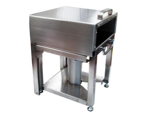
Установка спектрометрическая МКС-01А «МУЛЬТИРАД»
Установка спектрометрическая МКС-01А «МУЛЬТИРАД» предназначена для измерения активности и удельной активности альфа-, бета- и гамма- излучающих нуклидов в специально приготовленных образцах продуктов питания, кормов для сельскохозяйственных животных, воды, почвы, лесоматериалов, строительных материалов, а так же измерения мощности амбиентного эквивалента дозы и компарирования (поиска и сравнения) источников фотонного излучения с возможностью картирования точек измерения при подключении установки к GPS приёмнику.
МКС-01А «МУЛЬТИРАД» представляет собой лабораторное (в том числе, для передвижных лабораторий) оборудование с широким спектром возможностей и может применяться на предприятиях Минатома, Госсанэпиднадзора, МЧС, природоохранных предприятий различных ведомств.
Диапазон энергии регистрируемого излучения:
Максимальное значение входной загрузки статистическираспределенных импульсов для каждого измерительного тракта
Пределы допускаемой основной относительной погрешности измерения активности/удельной активности радионуклидов в исследуемых пробах
Пределы допускаемой основной относительной погрешности измерения МАЭД:
в диапазоне от 0,5 до 60 мкЗв/ч определяется по формуле, где Н * (10) – измеренное значение МАЭД в мкЗв/ч
Питание ПК от сети переменного тока
Питание измерительного тракта от источника постоянного тока
Мощность, потребляемая одним автономно функционирующим измерительным (совместно с ПК) трактом
Мощность, потребляемая одним автономно функционирующим измерительным трактом
Рабочие условия применения «МУЛЬТИРАД»:
по температурам окружающего воздуха
по влажности окружающего воздуха
по внешнему гамма-излучению с энергией фотонов 662 кэВ
напряженность постоянных магнитных полей и (или) переменных полей сетевой частоты
Пределы допускаемой дополнительной погрешности измерений относительно показаний в нормальных условиях при изменении температуры на каждые 10 °С
Поверку осуществляют в соответствии с разделами «Методика поверки» руководств по эксплуатации АЖНС.412131.001-01 РЭ, АЖНС.412131.001-02 РЭ и АЖНС.412131.001-03 РЭ,
согласованным «ФГУП «ВНИИФТРИ» 17 апреля 2006 г.
Межповерочный интервал — один год.
Основное поверочное оборудование:
- Установка поверочная дозиметрическая с источником 137 Cs , удовлетворяющая требованиям МИ 2050-90. Погрешность аттестации установки поверочной дозиметрической должна быть не более 5% при доверительной вероятности 0,95
- Фантом водный кубической формы, размерами 30х30х30 или из тканеэквивалентного материала по МИ 1788-87.
- Прибор дозиметрический, диапазон измерений мощности экспозиционной дозы 0-3000 МкР/час, основная погрешность прибора 10% .по МИ 1788-87
- Комплект радионуклидных источников альфа-излучения с доверительной относительной погрешностью, при доверительной вероятности 0,95, δ0=6% ( рабочий эталон 2-го разряда по ГОСТ 8.033-96);
- Комплект радионуклидных источников гамма-излучения с доверительной относительной погрешностью, при доверительной вероятности 0,95, δ0=6% ( рабочий эталон 2-го разряда по ГОСТ 8.033-96);
- Комплект радионуклидных источников бета-излучения с доверительной относительной погрешностью, при доверительной вероятности 0,95, δ0=6% ( рабочий эталон 2-го разряда по ГОСТ 8.033-96);
- Комплект образцовых радионуклидных источников специального назначения с доверительной относительной погрешностью, при доверительной вероятности 0,95, δ0=6% ( рабочий эталон 2-го разряда по ГОСТ 8.033-96);
«;s:4:»TYPE»;s:4:»html»;>
Назначение и область применения
Установка спектрометрическая МКС-01А «МУЛЬТИРАД» предназначена для измерения активности и удельной активности альфа-, бета- и гамма- излучающих нуклидов в специально приготовленных образцах продуктов питания, кормов для сельскохозяйственных животных, воды, почвы, лесоматериалов, строительных материалов, а так же измерения мощности амбиентного эквивалента дозы и компарирования (поиска и сравнения) источников фотонного излучения с возможностью картирования точек измерения при подключении установки к GPS приёмнику.
МКС-01А «МУЛЬТИРАД» представляет собой лабораторное (в том числе, для передвижных лабораторий) оборудование с широким спектром возможностей и может применяться на предприятиях Минатома, Госсанэпиднадзора, МЧС, природоохранных предприятий различных ведомств.
Основные технические характеристики
Диапазон энергии регистрируемого излучения:
Максимальное значение входной загрузки статистическираспределенных импульсов для каждого измерительного тракта
Пределы допускаемой основной относительной погрешности измерения активности/удельной активности радионуклидов в исследуемых пробах
Пределы допускаемой основной относительной погрешности измерения МАЭД:
в диапазоне от 0,5 до 60 мкЗв/ч определяется по формуле, где Н * (10) – измеренное значение МАЭД в мкЗв/ч
Питание ПК от сети переменного тока
Питание измерительного тракта от источника постоянного тока
Мощность, потребляемая одним автономно функционирующим измерительным (совместно с ПК) трактом
Мощность, потребляемая одним автономно функционирующим измерительным трактом
Рабочие условия применения «МУЛЬТИРАД»:
по температурам окружающего воздуха
по влажности окружающего воздуха
по внешнему гамма-излучению с энергией фотонов 662 кэВ
напряженность постоянных магнитных полей и (или) переменных полей сетевой частоты
Пределы допускаемой дополнительной погрешности измерений относительно показаний в нормальных условиях при изменении температуры на каждые 10 °С
Поверка
Поверку осуществляют в соответствии с разделами «Методика поверки» руководств по эксплуатации АЖНС.412131.001-01 РЭ, АЖНС.412131.001-02 РЭ и АЖНС.412131.001-03 РЭ,
согласованным «ФГУП «ВНИИФТРИ» 17 апреля 2006 г.
Межповерочный интервал — один год.
Основное поверочное оборудование:
- Установка поверочная дозиметрическая с источником 137 Cs , удовлетворяющая требованиям МИ 2050-90. Погрешность аттестации установки поверочной дозиметрической должна быть не более 5% при доверительной вероятности 0,95
- Фантом водный кубической формы, размерами 30х30х30 или из тканеэквивалентного материала по МИ 1788-87.
- Прибор дозиметрический, диапазон измерений мощности экспозиционной дозы 0-3000 МкР/час, основная погрешность прибора 10% .по МИ 1788-87
- Комплект радионуклидных источников альфа-излучения с доверительной относительной погрешностью, при доверительной вероятности 0,95, δ0=6% ( рабочий эталон 2-го разряда по ГОСТ 8.033-96);
- Комплект радионуклидных источников гамма-излучения с доверительной относительной погрешностью, при доверительной вероятности 0,95, δ0=6% ( рабочий эталон 2-го разряда по ГОСТ 8.033-96);
- Комплект радионуклидных источников бета-излучения с доверительной относительной погрешностью, при доверительной вероятности 0,95, δ0=6% ( рабочий эталон 2-го разряда по ГОСТ 8.033-96);
- Комплект образцовых радионуклидных источников специального назначения с доверительной относительной погрешностью, при доверительной вероятности 0,95, δ0=6% ( рабочий эталон 2-го разряда по ГОСТ 8.033-96);
Источник
Комплексы спектрометрические МУЛЬТИРАД-гамма
Комплексы спектрометрические «МУЛЬТИРАД-гамма» (далее — комплексы) предназначены для измерений энергии гамма- и рентгеновского излучений, испускаемых радионуклидами.
Скачать
Информация по Госреестру
| Основные данные | |
|---|---|
| Номер по Госреестру | 68925-17 |
| Наименование | Комплексы спектрометрические |
| Модель | МУЛЬТИРАД-гамма |
| Срок свидетельства (Или заводской номер) | 23.10.2022 |
Производитель / Заявитель
ООО «НТЦ «Амплитуда», г.Москва
Назначение
Комплексы спектрометрические «МУЛЬТИРАД-гамма» (далее — комплексы) предназначены для измерений энергии гамма- и рентгеновского излучений, испускаемых радионуклидами.
Описание
Принцип действия комплексов основан на преобразовании энергии ионизирующих излучений в электрические импульсы, которые с помощью аналого-цифрового преобразователя (АЦП) преобразуются в цифровой сигнал. Цифровой сигнал в дальнейшем обрабатывается посредством программного обеспечения (далее — ПО), установленном на персональном компьютере (далее — ПК).
— сцинтилляционного блока детектирования со встроенным в него или выносным цифровым многоканальным анализатором USB-4K, вакуумным ФЭУ и электронной частью,
— программного обеспечения «Прогресс-5»;
Блоки детектирования выпускаются в двух исполнениях:
— блок детектирования БДКС-25-02-1А содержат сцинтилляционный детектор на основе монокристалла CsI(Tl) диаметром 25 мм и высотой 5 мм;
— блок детектирования БДКС-25-02-2А содержат сцинтилляционный детектор на основе монокристалла NaI(Tl) диаметром 25 мм и высотой 10 мм.
Общий вид комплекса представлен на рисунке 1.
Схема пломбировки от несанкционированного доступа представлены на рисунке 2.
1 — пломба, закрывающая отверстия для настройки на блоке детектирования
2 — пломба на границе крышки и корпуса блока детектирования
Рисунок 2 — Схема пломбировки от несанкционированного доступа
Программное обеспечение
Комплексы работают под управлением программного обеспечения (ПО) «ПРОГРЕСС-5», которое позволяет последовательно выполнять следующие операции:
Структура программного обеспечения выражена в системе меню, выполняющих различные функции:
— запуск набора спектра измеряемого источника, остановка, очистка спектра;
— выполнение операций со спектром (сохранение в виде записи в рабочем журнале или в виде файла на диске, обработка спектра);
— выполнение стандартных задач: энергетическая калибровка, измерение фона, измерение
— отображение записи рабочего журнала с результатами измерений и вывод их в виде
— настройка режимов отображения, сохранения спектра и других опций программы. Уровень защиты программного обеспечения «средний» в соответствии с Р 50.2.077-2014.
Таблица 1 — Идентификационные данные программного обеспечения
Идентификационные данные (признаки)
Идентификационное наименование ПО
Номер версии (идентификационный номер) ПО
Цифровой идентификатор ПО
* Х — метрологически незначимая часть
Таблица 2 — Метрологические характеристики
Диапазон энергии регистрируемого излучения, кэВ:
— для блока детектирования БДКС-25-02-1 А
— для блока детектирования БДКС-25-02-2А
от 10 до 250 от 30 до 1500
Функция преобразования — линейная во всем диапазоне энергии регистрируемого излучения.
Предел допускаемой относительной погрешности характеристики преобразования (интегральная нелинейность), %, не более
Абсолютное энергетическое разрешение, кэВ, не более:
— в пике полного поглощения 59,54 кэВ ( Am)
— в пике полного поглощения 121,78 кэВ ( Eu)
Относительное энергетическое разрешение для блока детектирования БДКС-25-02-2А в пике полного поглощения 661,7 кэВ, %, не более
Относительная эффективность регистрации, не менее:
— для блока детектирования БДКС-25-02-1А
в пике полного поглощения 59,54 кэВ ( Am)
в пике полного поглощения 121,78 кэВ ( Eu)
— для блока детектирования БДКС-25-02-2А
в пике полного поглощения 59,54 кэВ ( Am)
в пике полного поглощения 121,78 кэВ (3 Eu) в пике полного поглощения 661,7 кэВ ( Cs)
0 0 0 0 0 m сч m сч ^ о» о» о» о» о»
Время установления рабочего режима, мин, не более
Время непрерывной работы, ч, не менее
Нестабильность градуировочной характеристики преобразования за 8 ч непрерывной работы (после установления рабочего режима), %
Таблица 3 — Основные технические характеристики
Параметры электрического питания:
— напряжение питания ПК от сети переменного тока, В,
— напряжение питания измерительного тракта от источника постоянного
Потребляемая мощность, В А, не более
Габаритные размеры, мм, не более
— БДКС-25-02-1 А (диаметрхвысота)
— свинцовая защита СЗГ-15 (длинахширинахвысота)
— температура окружающей среды, °С
— относительная влажность при +30 °С и более низких температурах без конденсации влаги, %
Средняя наработка на отказ, ч
Знак утверждения типа
наносится на блок детектирования на специальные таблички фотоспособом и типографским способом на титульные листы руководства по эксплуатации АЖНС.412131.003РЭ и паспорта АЖНС.412131.003ПС.
Комплектность
Таблица 4 — Комплектность средства измерений
Комплекс спектрометрический «МУЛЬТИРАД-гамма» в составе:
— сцинтилляционный блок детектирования
— цифровой многоканальный анализатор USB-4K
— калибровочные источники ОСГИ-А с радионукли-
Источник

X
Returning Customer
I am a returning customer
X
Register Account
If you already have an account with us, please login at the login form.
Ваша учетная запись создана!
Поздравляем! Ваш Личный Кабинет был успешно создан.
Теперь Вы можете воспользоваться дополнительными возможностями: просмотр истории заказов, печать счета, изменение своей контактной информации и адресов доставки и многое другое.
Если у Вас есть какие-либо вопросы, напишите нам.
Выход
Вы вышли из Личного Кабинета.
Ваша корзина покупок была сохранена. Она будет восстановлена при следующем входе в Ваш Личный Кабинет.

Альфа-радиометр сцинтилляционный «МУЛЬТИРАД-АР»
- Производитель: Амплитуда
- Модель:«МУЛЬТИРАД-АР»
Узнать цену
Назначение
- измерение суммарной альфа-активности в тонкослойных (спектрометрических) счётных образцах;
- измерение суммарной альфа-активности в толстослойных счётных образцах;
- измерение суммарной альфа-активности, осажденной на аэрозольном фильтре.
Область применения
- обеспечение радиационной безопасности питьевой воды, радиоэкология, групповой дозиметрический контроль и т.п.
Свойства
- светозащищенный корпус и наличие системы блокировки высокого напряжения при смене образцов;
- специальные сверхтонкие лавсановые защитные плёнки предохраняют детектор от загрязнения частицами вещества счётного образца;
- светодиодная стабилизация обеспечивает высокую температурную стабильность измерительного тракта.
Комплектация
- цифровой блок детектирования на основе сцинтиллятора ZnS (Ag);
- контрольный источник альфа-излучения;
- программное обеспечение «Прогресс»;
- руководство по эксплуатации;
- свидетельство о поверке;
- набор кювет.
| Тип детектора | сцинтилляционный на основе ZnS (Ag)2 ÷ 9 МэВ |
| Диаметр детектора | 70 мм |
|
|
тонкослойный: диаметр до 70 мм способ приготовления – электролитическое осаждение толстослойный: диаметр 70 мм масса 200 — 300 мг способ приготовления – спиртовое нанесение мелкодисперсных порошков, полученных радиохимическим концентрированием или выпариванием из проб воды, измельчением твердых проб |
| Расстояние от детектора до счетного образца |
1 мм |
| Энергетический диапазон | 2 ÷ 9 МэВ |
| Минимальная измеряемая активность |
для тонкослойных 0,05 Бк для толстослойных 0,04 Бк |
| Фон, не более | 0,003 имп./с |
| Программное обеспечение «Прогресс» |
расчет неопределенности измерений размещение результатов измерений в базе данных настраиваемая форма протокола измерений с учетом требований Заказчика |
| Подключение блока детектирования к ПЭВМ |
USB |
| Масса | 800 г |
(109)
(RA.RU.311258)
(RA.RU.311364)
(RA.RU.312738)
(RA.RU.311682)
(RA.RU.311258)
(RA.RU.311392)
(01.00291-2013)
(RA.RU.311510)
(РОСС RU.0001.310396)
(RA.RU.312368)
(РОСС СОБ 3.00047.2013)
(RA.RU.311315)
(RA.RU.312569)
(RA.RU.311249)
(RA.RU.310683)
(RA.RU.311341)
(RA.RU.311500)
(RA.RU.311273)
(0161)
(RA.RU.312055)
(RA.RU.310690)
(RA.RU.310680)
(RA.RU.311541)
(0521)
(RA.RU.311874)
(RA.RU.311249)
(1423)
(RA.RU.311466)
(RA.RU.311474)
(RA.RU.312477)
(RA.RU.311392)
(RA.RU.312477)
(РОСС СОБ 3.00047.2013)
(RA.RU.310586)
(RA.RU.311285)
(РОСС RU.0001.310193)
(RA.RU.311474)
(RA.RU.311364)
(RA.RU.311220)
(RA.RU.311312)
(109)
(RA.RU.311474)
(РОСС.RU.0001.310109)
(RA.RU.311478)
(RA.RU.311341)
(RA.RU.311315)
(RA.RU.311306)
(RA.RU.311479)
(RA.RU.311475)
(RA.RU.311463)
(RA.RU.311364)
(RA.RU.311494)
(RA.RU.311500)
(RA.RU.311466)
(273)
(RA.RU.311429)
(RA.RU.311249)
(RA.RU.312738)
(RA.RU.310577)
(RA.RU.311258)
(RA.RU.311466)
(RA.RU.311306)
(RA.RU.311273)
(109)
(RA.RU.311483)
(RA.RU.311500)
(01.00258-2011)
(RA.RU.311541)
(412)
(RA.RU.311488)
(RA.RU.311874)
(RA.RU.313417)
(RA.RU.312804)
(RA.RU.312302)
(RA.RU.311594)
(1744)
(RA.RU.311462)
(RA.RU.311682)
Установка предназначена для измерения активности гамма-излучающих радионуклидов в счётных образцах и других объектах, прижизненного определения активности гамма-излучающих радионуклидов в теле и органах человека (СИЧ-гамма) и определения радионуклидного состава исследуемых объектов.
Для измерения активности и удельной активности альфа-, бета- и гамма-излучающих нуклидов в специально приготовленных образцах продуктов питания, кормов для сельскохозяйственных животных, воды, воздуха, почвы, лесоматериалов, строительных материалов, а так же измерения мощности амбиентного эквивалента дозы и компарирования (поиска и сравнения) источников фотонного излучения с возможностью картирования точек измерения при подключении установки к GPS-приемнику, представляет собой лабораторное (в том числе, для передвижных лабораторий) оборудование с широким спектром возможностей и может применяться на предприятиях Минатома, Госсанэпиднадзора, МЧС, природоохранных предприятий различных ведомств.
Назначение
- Измерение активности гамма-излучающих радионуклидов в счётных образцах и других объектах
- Прижизненное определение активности гамма-излучающих радионуклидов в теле и органах человека (СИЧ-гамма)
- Определение радионуклидного состава исследуемых объектов
Область применения
- Радиационный контроль пищевой и сельскохозяйственной продукции, строительных материалов, продукции лесного хозяйства, питьевой воды и др.
- Охрана труда;
- Радиационный контроль и мониторинговые исследования в области радиоэкологии
- Технологический контроль на спецпредприятиях
- Научные исследования
Свойства
- Автоматический учет плотности вещества счётного образца
- Текущий контроль за работоспособностью спектрометра и стабильностью его метрологических характеристик
- Автоматический расчёт неопределённости каждого измерения
- Светодиодная стабилизация, обеспечивающая высокую температурную стабильность измерительного тракта
- Встроенный в блок детектирования АЦП с подключением к ПЭВМ через USB
Комплект поставки
- Цифровой блок детектирования
- Свинцовая защита
- Калибровочный источник
- Программное обеспечение «Прогресс»
- Руководство по эксплуатации
- Свидетельство о поверке
- Сосуд Маринелли 1 л (5 шт.)
- Чашка Петри (10 шт.)
Дополнительно
- Комплект оборудования для мониторинга радона
- Методика радиохимического приготовления счетных образцов
Технические характеристики
| Тип детектора | NaI (Tl) * |
| Параметр детектора |
размер детектора 63х63 мм энергетическое разрешение (ПШПВ) по линии CS-137 (662), не более 8,5% |
| Энергетический диапазон | 0,05 ÷ 3 МэВ |
| Минимальная измеряемая активность (на счётный образец): | |
|
по Cs-137 по Th-232 по Ra-226 по К-40 |
3 Бк 7 Бк 8 Бк 10 Бк |
| Подключение блока детектирования к ПЭВМ | USB |
| Основная погрешность измерения, не более | 10% |
| Масса со свинцовой защитой (без ПЭВМ) | 120 кг |
| Потребляемая мощность, не более | 200 Вт |
| Диапазон рабочих температур | +10 ÷ +40°C |
* в зависимости от измерительных задач в составе гамма-спектрометрического тракта могут применяться сцинтилляционные детекторы других типов (Csl(Tl), CsF2(Eu) и другие) различных размеров. Возможно также применение газонаполненных спектрометрических ионизационных камер. Технические характеристики спектра в случае применения нестандартных типов детекторов обсуждаются отдельно.
Документы
Размер: 11.2 Мб