Руководство на русском языке по техническому обслуживанию и ремонту кроссовых мотоциклов CZ 125 сс тип 984, 250 сс тип 980, 400 сс тип 981.
- Издательство: Ceske Zavody Motocyklove
- Год издания: 1975
- Страниц: 28
- Формат: PDF
- Размер: 4,3 Mb
Руководство на русском языке по техническому обслуживанию и ремонту мотоциклов Jawa-CZ 125 cc модели 355 и 175 сс модели 356.
- Издательство: CZM
- Год издания: 1959
- Страниц: 34
- Формат: PDF
- Размер: 18,9 Mb
Руководство на русском языке по техническому обслуживанию и ремонту мотоциклов CZ 125 cc тип 516.
- Издательство: CZM
- Год издания: 1988
- Страниц: 39
- Формат: PDF
- Размер: 6,3 Mb
Руководство на русском языке по техническому обслуживанию мотоциклов CZ 250 тип 513 и CZ 400 тип 514.
- Издательство: —
- Год издания: —
- Страниц: 75
- Формат: PDF
- Размер: 2,7 Mb
Руководство на русском языке по техническому обслуживанию и ремонту мотоциклов CZ 350 тип 472.3.
- Издательство: CZM
- Год издания: 1976
- Страниц: 57
- Формат: PDF
- Размер: 11,6 Mb
Руководство на русском языке по техническому обслуживанию и ремонту мотоциклов CZ 350 тип 472.5.
- Издательство: CZM
- Год издания: 1983
- Страниц: 29
- Формат: PDF
- Размер: 6,3 Mb
Руководство на русском языке по техническому обслуживанию и ремонту мотоциклов CZ 350 тип 472.6.
- Издательство: CZM
- Год издания: 1986
- Страниц: 55
- Формат: PDF
- Размер: 8,4 Mb
Руководство на русском языке по техническому обслуживанию мотоциклов CZ 350 тип 472.6.
- Издательство: CZM
- Год издания: 1986
- Страниц: 42
- Формат: PDF
- Размер: 5,0 Mb
В практическом пособии приведены устройство и технические данные легких (без коляски) мотоциклов отечественного производства, чехословацких ЯВА и ЧЗ, а также спортивных. Помещены указания по их демонтажу, сборке и ремонту отдельных деталей, сведения по обкатке, эксплуатации и техническому обслуживанию.
- Издательство: Техника
- Год издания: 1984
- Страниц: 98
- Формат: DjVu
- Размер: 2,6 Mb
В руководстве представлена информация об устройстве и работе всех узлов и агрегатов мотоцикла.
- Издательство: Алфамер
- Год издания: —
- Страниц: 220
- Формат: —
- Размер: —

Меню сайта
-
Мотообъявления
-
Мануалы скачать
-
Мануалы читать
-
Обратная связь
-
Гостевая книга
-
Мотоновости
-
Фотоальбом
-
Микрофиши
-
Мотостатьи
| Поиск по сайту |
| Категории раздела | ||||||||||||||||||
|
| Статистика |
|
Онлайн всего: 1 Онлайн гостей: 1 Онлайн пользователей: 0 |
| Наш опрос |
|
В поездке документы на Ваш мотоцикл находятся Дома В кармане В мотоцикле Нет документов [ Результаты · Архив опросов ] Всего ответов: 250 мануалы для:[ИЖ П] |
 |
 |
 |
Пятница, 19.05.2023, 00:51 Приветствую Вас Гость | RSS | Вход |
| Все мото здесь!!! | |||
|
| Главная » Файлы » JAWA |
ЧЗ 350 тип 472.3
[  СКАЧАТЬ БЕСПЛАТНО МАНУАЛ ДЛЯ JAWA ЧЗ 350 тип 472.3 (11.59 Mb) СКАЧАТЬ БЕСПЛАТНО МАНУАЛ ДЛЯ JAWA ЧЗ 350 тип 472.3 (11.59 Mb)
] |
07.04.2016, 15:56 |
Название: Руководство по обслуживанию Ява-ЧЗ sport 350 тип 472.3 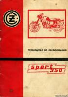 Автор: Производитель Формат: rar/jpg Размер: 11,6 МБ Качество: Хорошее Язык: Русский Жанр: Мото-мануал Издательство: Заводское издательство Страниц: 55 Год издания: 1976 Описание: Техническое описание и руководство по обслуживанию Ява-ЧЗ 350 тип 472.3 на русском языке. |
|
Категория: JAWA | Добавил: Talabas07 |
|
| Просмотров: 2028 | Загрузок: 533 | Комментарии: 2 | Рейтинг: 0.0/0 |
Похожие файлы:
- 559/04 и 360/00
- 353/04 и 354/04
- 634-7-91 и 634-7-01
- 634-01
- 350/634
- ЧЗ 355/356
- ЧЗ 350 тип 472.5
- ЧЗ 350 тип 472.6
- ЧЗ 350 тип 472.5
- ЧЗ 350 тип 472.6
- ЧЗ 350 тип 472.6
- ЧЗ тип 984, 980, 981
- ЧЗ 250 тип 513, 400 тип 514
- ЧЗ 125 типа 516
- Яветта 50 см типа 551
| Всего комментариев: 2 | |
|
Порядок вывода комментариев:
1 • 11:16, 03.07.2021 требует пароль
2 • 11:37, 03.07.2021 Здравствуйте. Файл исправили. Можно скачивать без пароля. Спасибо за сигнал. |
|

Войдите:
![]()
libcats.org
Главная →
Техническое описание и руководство по обслуживанию CZ 350
Скачать книгу бесплатно (pdf, 6.31 Mb)
Читать «Техническое описание и руководство по обслуживанию CZ 350»
EPUB | FB2 | MOBI | TXT | RTF
* Конвертация файла может нарушить форматирование оригинала. По-возможности скачивайте файл в оригинальном формате.
Популярные книги за неделю:
#1
![]()
Ф.И.Бурдейный, Н.В.Казанский. Карманный справочник радиолюбителя-коротковолновика (1959, DjVu)
440 Kb
#2
![]()
Я.Войцеховский. Радиоэлектронные игрушки (1977, djvu)
13.76 Mb
#3
![]()
Подготовка саперов, подразделений специального назначения по разминированию
Категория: Научно-популярная литература (разное)
1.49 Mb
#4
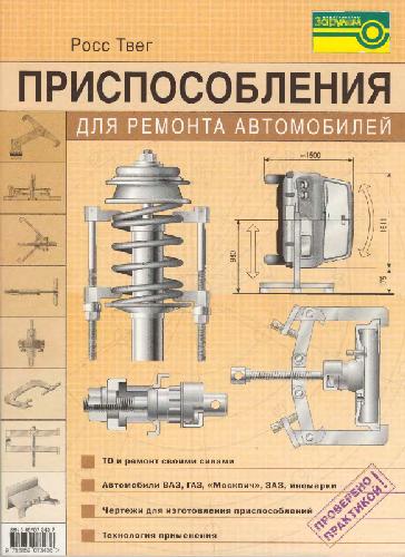
Приспособления для ремонта автомобилей
Росс Твег
Категория: civil, civil, transport
7.37 Mb
#5

Разгаданные загадки третьего рейха. 1933-1941
Безыменский Лев
Категория: society, society, history
5.17 Mb
#6

128 советов начинающему программисту
Очков В.Ф., Пухначев Ю.В.
Категория: computers, computers, prog
8.91 Mb
#7

Английский язык в картинках
I.A. Richards; Christine M. Gibson
Категория: Иностранные языки
5.77 Mb
#8

Ограждение участка. Ограды. Заборы. Калитки. Ворота
В.И.Рыженко
Категория: Строительство
1.23 Mb
#9
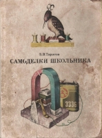
Самоделки школьника
Тарасов Б.В.
Категория: science, science, technical, hobby, oddjob
41.91 Mb
#10
![]()
Наука и жизнь.Маленькие хитрости
Категория: E_Engineering, EM_Mechanics of elastic materials
3.50 Mb
Только что пользователи скачали эти книги:
#1
![]()
Научная этика
Циолковский Константин Эдуардович
Категория: Научная литература
106 Kb
#2

Сети связи и системы коммутации
Абилов А.В.
2.81 Mb
#3
Химия и современность: Пособие для учителя
Третьяков Ю.Д.
Категория: Chemistry, School and Popular
5.77 Mb
#4
Дикорастущие лекарственные растения СССР
А. Ф. Гаммерман, И. И. Гром
Категория: Ботаника, Растения, Справочники
8.36 Mb
#5

Что приготовить в горшочках. Лучшие рецепты
Сост. А. Архангельская
Категория: house, house, cook
6.55 Mb
#6
Математическое моделирование процессов рафинирования алюминиевых сплавов: Методическое пособие
Дурина Т.А., Черный А.А.
Категория: Литейное производство
302 Kb
#7
Основы математического моделирования радиотехнических систем: Учебное пособие
Монаков А.А.
Категория: Электроника. Радиотехника
962 Kb
#8
Сборник текстов и упражнений: для студентов химического факультета, изучающих французский язык
Некрасов С.В.
Категория: Иностранный язык
482 Kb
#9

Культура и обучение иностранным языкам
Галина Васильевна Елизарова
Категория: science, human, society, lang, society, culture
2.60 Mb
#10

Разработка и исследование метода классификации библиографической текстовой информации : диссертация … кандидата технических наук : 05.13.01
Некрасов Иван Валерьевич
Категория: Литература, Библиотечное дело
6.85 Mb
В этом руководстве описан мотоцикл CZ 350 тип 472.5.А также подробно рассмотрены ремонт и регулировка двигателя и других агрегатов даного мотоцикла, приведена полная инструкция по эксплуатации, рекомендуемая изготовителем.
Год выпуска: 1983
Язык: Русский
Формат: PDF
Количество страниц: 56
Скачать с
Внимание! У Вас нет прав для просмотра скрытого текста.

Размещено в разделе Руководства для авто, 15.02.2010 г.,
Просмотров 9 489,
Комментариев 0
Еще похожие на «Техническое описание и руководство по обслуживанию CZ 350 тип 472.5» материалы:
Сейчас посетители сайта читают следующие материалы на ГомельАвто:
Юхин Н.А.Год: 1997Страниц: 65Формат: pdfРазмер: 8,94 Мб Качество: хорошееЯзык: русский
В учебном пособии рассмотрены формирование сварных соединений, особенности нагрева и деформации металла, технология и оборудование контактной сварки современных конструкционных материалов. описано применение полупроводниковых элементов и логических устройств для программирования режимов сварки различных систем контроля и автоматического регулирования сварки, а также средств механизации и автоматизации вспомогательных операций.
Большая автомобильная энциклопедия содержит информацию о более чем 5000 автомобилях более чем 120-ти различных марок с обзорами, тестами и характеристиками.
Комментарии к этому материалу:
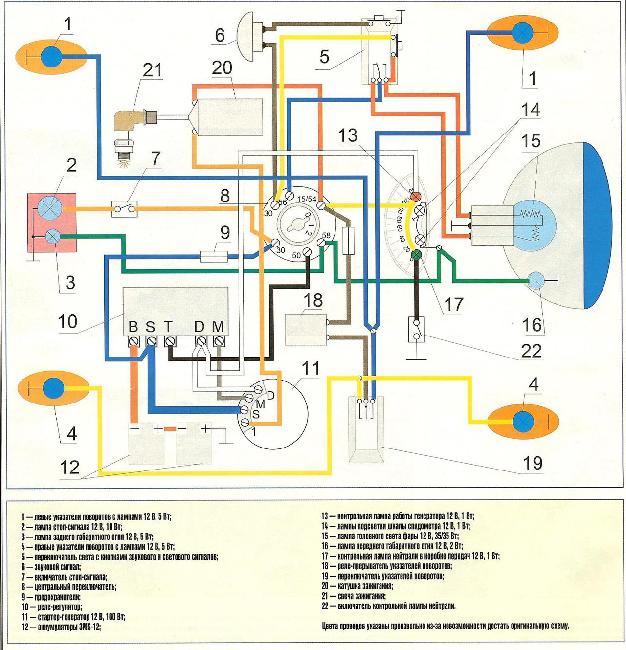
Схемы электрооборудования мотоциклов Чезет
В этом посте три схемы электрооборудования мотоциклов Чезет и одна схема электрооборудования мотороллера Chezeta. Для увеличения изображения, кликните по нему мышкой. Схема мотоцикла CZ 472-5.
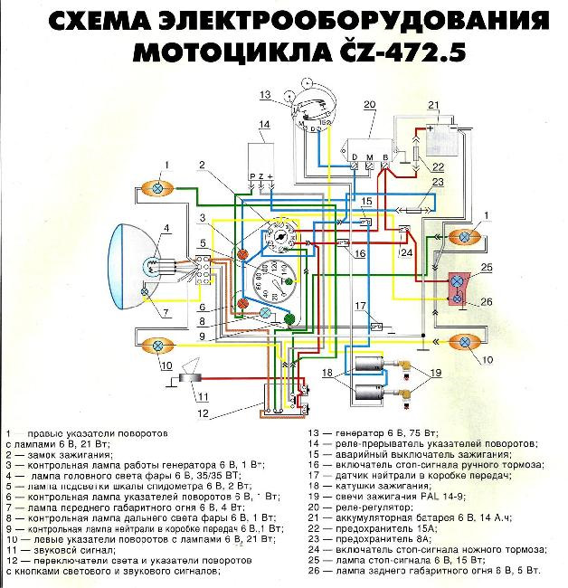 Схема мотоцикла CZ 472-6.
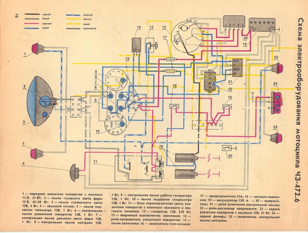 Схема мотоцикла CZ 472-3.
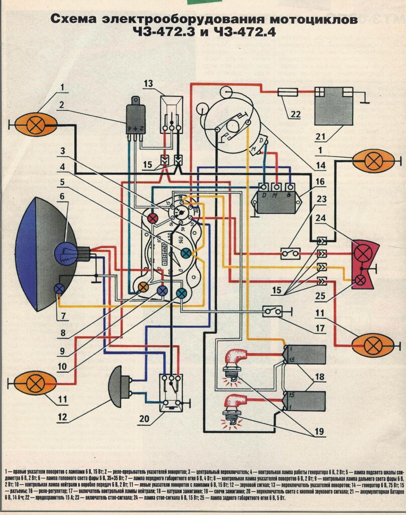 Схема мотороллера Chezeta 502-1.
 Схемы электрооборудования мотоциклов Ява здесь.
0
4 988 просмотров
Вам также может быть интересно
Сегодня автомобили стали частью нашей жизни, мы привыкли садиться в машину, запускать двигатель и
Обзор 1вин официальный сайт, запущенного в 1999 г. Как и Bwin, их рост стремителен.
В сегодняшнем посте привожу четыре схемы электрооборудования мотоциклов Ява 350 самых популярных моделей. Для
В этой статье три электрические схемы мотоциклов Восход самых популярных моделей. Это модификации Восходов:
Схема электрооборудования мотоцикла Suzuki GN400. Для увеличения рисунка кликните по нему левой кнопкой мышки.
Схема электрическая мотоцикла Pannonia TLF-250, TLD-250 и TLB-250 Для увеличения рисунка кликните по нему
-
Contents
-
Table of Contents
-
Bookmarks
Quick Links
orkshop
W
anual
M
This manual covers all Cezeta and N-Zeta models
Summary of Contents for N-Zeta 501/01, 501/03
-
Page 1
This manual covers all Cezeta and N-Zeta models… -
Page 2: Table Of Contents
— 1 — INTRODUCTION ………………… — 4 — CARBURETTOR CLEANING AND MAINTENANCE ……….- 5 — Jikov 2924 M 13 carburettor ……………………- 6 — To Dismantle The Float Chamber: ………………….- 6 — To Set The Carburettor According To The Manufacturers Specifications: ……… — 7 — Jikov 2924 S 11 Carburettor for the 501/03 to /05 models;…
-
Page 3
— 2 — To Dismantle The Gearbox And Crankshaft Mechanism …………..- 27 — Dismantling The Crankshaft Assembly ………………..- 28 — 501 Model – 356-12-230 …………….- 31 — Connecting Rod For The 502 Model – 450-12-230 ……………………..- 31 — Assembling The Engine …………………….. -
Page 4
— 3 — PAL 02-9421.04 Regulator With Contactor – Technical Data And Setting ……..- 48 — Regulator With Contactor — Mechanical Checking …………….- 49 — Operation Checking ……………………..- 49 — PAL 02-9490.60 Dynastart – Technical Data ………………- 50 — Dynastart –… -
Page 5: Introduction
— 4 — N Z E T A S c o o t e r R e p a i r M a n u a l Introduction This book represents the Repair Manual for owners of NZETA scooters made by the world famous CZ Motorcycle Works in Strakonice Czechoslovakia then assembled and finished by Jawa New Zealand.
-
Page 6: Carburettor Cleaning And Maintenance
— 5 — Carburettor Cleaning and Maintenance On most occasions, carburettor faults are due to impurities entering with the petrol or air. The time for regular carburettor cleaning will depend on the manner in which the machine is used. It is not recommended to carry out any carburettor repairs apart from washing it in clean petrol and setting according to the maker’s instructions.
-
Page 7: Jikov 2924 M 13 Carburettor
— 6 — All these jobs are done without removing the carburettor from the crankcase, the carburettor being accessible after opening the side door. The main jet is also accessible through the side door. To clean it, fine horse hair should be employed and not a piece of wire or any other hard object.
-
Page 8: To Set The Carburettor According To The Manufacturers Specifications
— 7 — The idling jet #17, the pilot, air screw #18 and the throttle valve stop screw #15 are located on the R. H. side of the carburettor and are accessible through the bodywork side door. When repairing the float, push out the float spindle #31a first thus freeing the float #31.
-
Page 9
— 8 — The carburettor is set in the Works for running in, and it has to be reset after the first 2000 km / 1200miles to the following values: Main Jet 100 to 102 to Solex Idling Jet 55 to Solex Needle position notch from the top Pilot air screw… -
Page 10: Jikov 2924 S 11 Carburettor For The 501/03 To /05 Models
— 9 — Jikov 2924 S 11 Carburettor for the 501/03 to /05 models; Jikov 2924 S 13 Carburettor for the 502/00 to /01 model Fig.2 These are monoblock type carburettors. They are also equipped with a choke device for making the mixture rich to assist in starting the engine when cold. The main jet #24 is located in the jet carrier #23 and is accessible after being unscrewed.
-
Page 11: To Set The Carburettor According To The Manufacturers Specifications
— 10 — To Set The Carburettor According To The Manufacturers Specifications, Proceed As Follows: First check the throttle valve #4 needle position. Slacken the lock nut #8; screw the cable guide #9 into the mixing chamber top #7 thus freeing the throttle valve #3.
-
Page 12
— 11 — Fig. 2… -
Page 13: Induction Silencer Maintenance And Cleaning
— 12 — Induction Silencer Maintenance and Cleaning For the 501/01 – 03 – 05 models fig. 3 The silencer serves to reduce the engine noise level and replaces the normal air cleaner at the carburettor. For its correct operation, it must be maintained as follows: After about 3000 –…
-
Page 14: E N G I N E
— 13 — E n g i n e The following jobs can be carried out without removing the engine from the bodywork: Removal of the cylinder barrel and head for replacement, re-boring or decoking, cleaning or replacement of the piston, replacement of the connecting rod small end bush, ignition advance setting, removal of the ignition and dynamo, replacement of the gearbox chain sprocket, the primary drive chain and final drive chain, replacement and adjusting of the clutch and gear change mechanism, removal…
-
Page 15: Piston
— 14 — To dismantle the cylinder barrel, it is necessary to first unscrew the studs fastening the cylinder barrel to the crankcase. Thread two nuts onto the studs and tighten them onto each other. Now unscrew them together with the stud by turning the bottom nut.
-
Page 16: Piston Grading According To Diameter D2 — Model 502
— 15 — Piston Grading According To Diameter D2 – Model 502 Fig.6 A – 0.01 B – 0.01 C – 0.01 Nº. Standard 57.860 57.870 57.880 450-12-026 rebore 58.110 58.120 58.130 450-12-027 rebore 58.360 58.370 58.380 450-12-028 rebore 58.610 58.620 58.630 450-12-029…
-
Page 17: Cylinder
— 16 — Cylinder For model 501 scooters, only cylinders with increased bore by 0.01mm as compared to the motorcycle engines have to be employed. Cylinder bores for the individual gradings are indicated in this table; the cylinder barrels are marked on the top flange beside the letter A, B, C determining the corresponding pistons with the letter “S”.
-
Page 18: Gudgeon Pin Bush For Models 501/01, 03, 05
— 17 — Gudgeon Pin Bush For Models 501/01, 03, 05 Gudgeon pin bush diameter is 15.025 0.01mm for standard gudgeon pin grading = dia. 15.000 – 0.0025mm, grading = dia. 14.9975 – 0.0025mm and 15.125 – 0.01mm for oversize gudgeon pin dia. 15.1 – 0.004mm. For Models 502/01, 00 Gudgeon pin bush diameter is 18.25 0.01mm for standard gudgeon pin grading…
-
Page 19: Fitting The Cylinder Barrel And Cylinder Head
— 18 — Fitting The Cylinder Barrel And Cylinder Head Clean the Crankcase seating face and preferably a new gasket under the Cylinder Barrel. Provide the Cylinder Barrel with a coating of clean oil inside, move the piston to TDC by means of the kick starter pedal and then fit the barrel. When fitting the cylinder barrel, take care to have the piston rings correctly placed with their ends to the peg in the piston groove.
-
Page 20
— 19 — Fig. 7… -
Page 21
— 20 — After removing the fan assembly from the bodywork, remove the rubber cover #5 from the rotor hub. Free the circlip #9 and pull the fan rotor #4 together with the bearings #6, 7 off the fan body shaft #3 using a universal puller or S-37 with extension S-48. -
Page 22: Setting The Ignition Advance
— 21 — The fan required very little maintenance. After approximately 10,000 km / 6,000 miles, remove the fan rotor from its shaft, clean away any old grease from the space between the bearings and apply a small amount of motor grease to the space. It is necessary to check the Vee-belt from time to time for wear.
-
Page 23: To Dismantle The Clutch Operating Bracket
— 22 — Fig. 10 After pushing out the carbon brushes, take the dynastarter out of the crankcase. Slacken the cam bolt #1 and tap the cam lightly from side to side taking care not to mark it and remove it from the shaft. Screw puller S-49 or a long M10 bolt /one can be obtained from under the luggage compartment securing the rear suspension unit to the bodywork/, into the hole in the centre of the rotor.
-
Page 24: Removal Of The Gearbox Sprocket
— 23 — gearbox sprocket shaft the clutch operating rod. The bracket should be dismantled further only when some of the bracket parts are worn. Removal Of The Gearbox Sprocket — is the same for both models. After removing the RH crankcase side cover and the clutch operating bracket, straighten the tabs of the lock washer under the sprocket nut.
-
Page 25
— 24 — Remove the recessed pins on the clutch pins compressing the clutch springs wither with the special tool S-9, or with a screwdriver Fig. 12 or possibly with a flat spanner. Push the pin out of the opening and remove the spring from the can. -
Page 26: To Remove The Kick Starter Quadrant
— 25 — To Remove The Kick Starter Quadrant. Remove the kick starter quadrant together with the return spring from the gear change shaft. Take care of the return spring when taking the parts off. Further remove the spacer which is on the gear change shaft. To assemble, proceed in the reverse manner.
-
Page 27: To Replace The Crankshaft And Gearbox Output Shaft Seals
— 26 — To Replace The Crankshaft and Gearbox Output Shaft Seals When replacing the seals on the crankshaft RH end, it is necessary to first remove the dynastarter as described in the paragraph dealing with its removal. Next remove the three screws securing the seal holder and remove the holder and seal together.
-
Page 28: To Dismantle The Gearbox And Crankshaft Mechanism
— 27 — To Dismantle The Gearbox And Crankshaft Mechanism To separate the crankcase halves, dismantle the gearbox and crankshaft assembly are very exacting jobs which should be done under the supervision of an experienced motorcyclist, or entrusted to a service repair shop; this is preferable as the workshops are equipped with special tools supplied by the manufacturers.
-
Page 29: Dismantling The Crankshaft Assembly
— 28 — If the driving gear with hub or the seal are not to be replaced, the gearbox sprocket need not to be removed before separating the crankcase halves. Remove the gear change shaft, the selector fork guide rod and the gears with shafts. Slacken the four screws holding the cam plate to the LH crankcase and remove the cam plate.
-
Page 30
— 29 — Checking method before pressing together the crankshaft assembly and of the pressed together components. The crank pin with the crank web has to be checked on the measuring table between two centres by means of the indicating dial Fig.18. Fig. -
Page 31
— 30 — Connecting Rod – Rollers — Crank Pin Fig.19 — Crankshaft Assembly 356 Assembly Table For The 501 Model Corresponding grading Roller grading marked connecting and crank pin C D E G H I M N O Connecting rod 12 12 12 10 8 18 18 18 16 14 Crank pin… -
Page 32: Connecting Rod For The 501 Model – 356-12-230
— 31 — Connecting Rod For The 501 Model – 356-12-230 502 Model – 450-12-230 Roller – 353-12-012 Crank pin – 355-12-141 353-12-012 450-12-141 Inner diameter Outer diameter Outer diameter marked 1 marked A marked I 29.900 + 0.002 4.002 — 0.002 21.900 — 0.001 29.902 + 0.002 4.000 — 0.002…
-
Page 33: Assembling The Engine
— 32 — Assembling The Engine Before assembling the engine all its parts have to be washed with petrol and dried. The seating faces of the crank case halves and of the L.H. side’ cover have to be cleaned from the old sealing compound by careful scraping. Any unevenness on the seating faces should be smoothed out on a lapping plate with paste.
-
Page 34
— 33 — Screw the cam plate to the L.H crankcase half taking care of the location of the centring screw. Locate the assembled main shaft, with the bottom, second and third gear pinions, into the L.H crankcase half / for model 502 do not omit to secure the second gear pinion with the spring ring Fig. -
Page 35
— 34 — 10. Fit the lay shaft with the lay shaft third and top gear pinions 11. Insert the rod into the selector forks and tighten the securing screw. Fig.23. Fig 23 12. Press the driving gear with hub into the R.H. crankcase half. 13. -
Page 36
— 35 — The assembly of the clutch and L.H side cover, the dynastarter, the clutch operating bracket and the L.H. side cover has been described in the preceding paragraphs… -
Page 37: C Y C L E P A R T
— 36 — C y c l e P a r t The cycle part of both the 501 and 502 NZETA models looks alike and consists of monocoque bodywork: reinforced in the rear portion for the fastening of the spare wheel brackets.
-
Page 38: Model 502 — Removing The Rear Drive Chain
— 37 — After disconnecting the chain connect an old chain to it and by removing the chain from the pivoted arm the, old chain is being pulled at the same time; the old chain will make the fitting of the, new, or serviced chain easier. Having removed the chain, carry out its maintenance, shorten it if required using de-riveter S-6, When replacing the serviced and shortened chain, or fitting a new chain, connect it to the old chain left in the pivot arm and removing this old chain pull the…
-
Page 39: Front Fork Removal
— 38 — of ground over which the machine is ridden and the medium in which it is employed the chain has to be greased approx. after every 1,200 to 3,000 miles / 2,000 to 5,000 km/. First wash the chain in paraffin. After drying, place the chain for about 3 hours in a lightly heated graphite lubricant / tallow mixed with 10% colloidal graphite/.
-
Page 40: Model 501-Removal Of The Suspension Damper
— 39 — guard will be completely separated from the fork. Now take out the pins from the pivoted arm and using puller S-20, drive out the bushes. Press the rubber bushes out of the fork. After replacing all worn parts, reassemble by proceeding in the reverse manner.
-
Page 41: To Dismantle The Pivoted Rear Arm
— 40 — towards the rear of the machine. To replace proceed in reverse manner. To Dismantle The Pivoted Rear Arm In this respect the two models differ. Model 501 will be described first. For the 501 model, the pivoted rear arm can be dismantled only when the power unit has been taken out of the bodywork.
-
Page 42: Dismantling The Headlamp
— 41 — Dismantling The Headlamp — Both Models First slacken the screw and remove the headlamp assembly. Compressing the cap and rotating it clockwise take the cap off and together with it the bulb holder with the bulb. To replace the headlamp glass, proceed as follows: Remove the cotter pin and turn out the screw with rubber wash.
-
Page 43: To Dismantle The Choke Device
— 42 — In model 502 remove the cotter pin thereby freeing the bodywork door. Removal of the pin will free the lock and this can now be taken out. The bodywork door will be freed after the cotter pin has been removed. To dismantle the catches in model 501, proceed in the same manner as for the instrument box door.
-
Page 44
— 43 — pushing out the joint, remove the gear change pedal. To reassemble, proceed in reverse manner. To adjust the gear change pedal position, slacken the rod lock nuts and either screw the rod into or out of the socket. -
Page 45: E L E C T R I C A L E Q U I P M E N T
— 44 — E l e c t r i c a l E q u i p m e n t Dynamo The DC 45 W 6 V dynamo serves as the source of the electric current. It supplies the current to the ignition circuit /terminal I A/ and into the lighting circuit /terminal 51/.
-
Page 46: Pal Voltage Regulator 6 V
— 45 — Fig. 28 PAL Voltage Regulator 6 V Fig. 28 The PAL 6 V regulator and the mechanical setting of the individual contact gaps is the same as that of the 12V dynastart regulator. The difference between the 6V and l2V regulators is in the voltage and current coil winding which is always adapted to the voltage.
-
Page 47: Pal Dynastarter
— 46 — PAL Dynastarter Details of design: the dynastart parts are similar to those in the 6V 45W dynamo. The rotor is provided with a winding, the outlets of which are soldered to the individual commutator plates. Inside the rotor there is a tapered opening for fitting on to the crank pin.
-
Page 48: Operation Of The Dynastart With The Regulator And Contactor
— 47 — Fig. 29 Operation Of The Dynastart With The Regulator And Contactor Starter With the ignition key in starting position the current flows from the two six Volt 5 M S 12 starting batteries via the connected contacts in the switch box into the winding in the contactor, magnetising the contactor iron core and attracting the armature.
-
Page 49: Pal 02-9421.04 Regulator With Contactor — Technical Data And Setting
— 48 — Dynamo With the engine running and the starting circuit disconnected, the starter field winding is without current and the dynastart operates as a dynamo with voltage regulator. The operation is similar to that of the 6V 45W dynamo with PAL regulator. The remaining magnetism in the pole shoes excites current in the rotating rotor, the voltage of which grows in proportion to it speed.
-
Page 50: Regulator With Contactor — Mechanical Checking
— 49 — Regulator With Contactor — Mechanical Checking Mechanical checking of the regulator with contactor has to be carried out in case of faulty regulator operation. The regulator has to be checked for completeness of parts, the contacts cleaned, metal filings and dirt removed from the regulating system.
-
Page 51: Pal 02-9490.60 Dynastart — Technical Data
— 50 — PAL 02-9490.60 Dynastart – Technical Data Dynamo Nominal voltage Operational voltage 13.5 V Nominal output up to 100W Nominal current up to 7.5 amps, Operational voltage r.p.m. 1,700 Starter Nominal voltage Operational voltage at engagement torque 9 V minimum Engagement torque at 5º…
-
Page 52: Lights
— 51 — Lights The headlight is equipped with a two filament bulb, the bulb in the model with a dynamo is 25/25 W, that in the dynastart model is 35/35 W. Headlamp beam adjustment is by tilting the reflector after slackening the screw on the top of the headlamp nacelle.
-
Page 53
— 52 — This Workshop Manual is an OCR copy of the original NZETA Workshop Manual as supplied to dealers throughout New Zealand. It is an English translation of the CEZETA Workshop Manual, and as such, some parts may not apply to NZETA models as supplied.
Реставрация мотоцикла Cezet 350 (пошагово, 37 фото)
К Чезету я всегда был равнодушен, но Олег показал как должен выглядеть настоящий CZ и я запал… Хотя у меня сейчас несколько мотоциклов разобрано (ждут весны для покраски), решил делать еще один.

Давно (года 2 назад) мне предлагали cz 350 с неисправным мотором, я позвонил, и он не продан, поэтому по сходной цене я его приобрел.

После детального рассмотрения немножко расстроился, т.к список нужных запчастей увеличился от первоначального, но тогда я вспомнил, что мне предлагали cz на запчасти, и он тоже был куплен.
Осмотр донора порадовал: родная резина перед — зад, пробег 11 тыс., решил снять головку, а там все соответствует пробегу — есть что восстанавливать. Восстанавливать решил первый мотоцикл, т.к. он с документами, второй в более лучшем состоянии пойдёт на запчасти.

Разобрал мотоцикл до основания, отпескоструил раму.

Почистил и перебрал колеса


Спустя несколько дней покрасил некоторые детали в чёрный цвет.

Детали

Удалось найти совсем новые Чехословацкие глушители, лежащие много лет у дедка в сарае.

Покрасил вилку матовой краской, собрал зад маятник. Втулки из рамы не выпрессовывал, они из бронзы — и практически не износились.


Покрасил облицовку. Цвет подобрал как родной 1025 серия лада.

Нанёс на заднее крыло цировки, как на мотоцикле с завода.

Рама начинает обростать “мясом”


Новенькие наклейки на бардачки.


Далее взялся за мотор. После переборки выкрасил цилиндры термостойкой краской, отполировал крышки.


Далее проводка — перебрана и перепаяна. Некоторые провода заменены аналогичными новодельными соответствующими по цвету старым.

Дошла очередь и до поворотов. Все пластмасски-стёклышки отполированы. Лампочки естественно новые

Ножки поворотников оцинкованы.

На мотоцикле


Весь крепёж и мелкие детали тоже были отданы из забраны с цинковки. Теперь не поржавеют 


Отпескоструил и покрасил основание седла. Чехол новый, как оригинальный.


Спустя почти год выкатил на улицу собранный мотоцикл. Завёлся не сразу, пришлось немного повозится, но после устранения мелкой неисправности он завёлся и я наконец то прокатился на нём. Результатом доволен


Источник: forum.jawaold.su