| Название: | Размер: | Посещения: |
| Ducati 1000 le smart 2006 часть списка | 3.12 MB | 10898 |
| Ducati 1000 s 2006 часть списка | 2.92 MB | 9036 |
| Ducati 1000 ss 2003 часть списка | 4.68 MB | 9345 |
| Ducati 1000 SS Eu 03 Ed часть списка | 4.68 MB | 8661 |
| Ducati 1000Dark Eu 03 Ed часть списка | 4.29 MB | 7867 |
| Ducati 1000S Eu 03 Ed часть списка | 4.34 MB | 7894 |
| Ducati 1098 2007 руководство по ремонту | 30.92 MB | 27363 |
| Ducati 1098 2007 часть списка | 4.47 MB | 9462 |
| Ducati 1098 2008 часть списка | 4.49 MB | 8966 |
| Ducati 1098 r 2008 часть списка | 4.75 MB | 8631 |
| Ducati 1098 s 2007 часть списка | 4.21 MB | 8724 |
| Ducati 1098 s 2008 часть списка | 4.24 MB | 9493 |
| Ducati 1098 s tricolore 2007 часть списка | 4.96 MB | 8589 |
| Ducati 160 monza jr руководство по ремонту intretinere | 3.84 MB | 9426 |
| Ducati 1975 1976 750 900 ss часть списка | 6.93 MB | 8283 |
| Ducati 350 1973 mototrans монтажная схема | 66.79 Kb | 8295 |
| Ducati 350 650 indiana часть списка | 9.64 MB | 9786 |
| Ducati 350 mototrans 1973 монтажная схема | 66.79 Kb | 7948 |
| Ducati 350 mototrans монтажная схема | 1.11 MB | 8791 |
| Ducati 350 scrambler 1968 руководство по ремонту intretinere | 6.26 MB | 12099 |
| Ducati 500 sl pantah руководство по ремонту | 10.95 MB | 11897 |
| Ducati 500 sl pantah часть списка | 6.19 MB | 8198 |
| Ducati 600 sl pantah часть списка | 6.53 MB | 12136 |
| Ducati 620 S 2002 | 4.10 MB | 13608 |
| Ducati 620 S Eu 03 Ed 2000 часть списка | 4.10 MB | 9403 |
| Ducati 748 2000 часть списка | 3.35 MB | 9128 |
| Ducati 748 2001 часть списка | 3.28 MB | 7971 |
| Ducati 748 2002 | 2.57 MB | 9745 |
| Ducati 748 916 | 76.68 MB | 21042 |
| Ducati 748 996 1999 руководство по эксплуатации | 3.13 MB | 9693 |
| Ducati 748 996 2000 руководство по эксплуатации | 2.65 MB | 9112 |
| Ducati 748 Eu 2002 часть списка | 2.57 MB | 7857 |
| Ducati 748 r 2001 часть списка | 2.85 MB | 7743 |
| Ducati 748 r 2002 часть списка | 2.93 MB | 7630 |
| Ducati 748 R руководство по эксплуатации | 1.38 MB | 9307 |
| Ducati 748 s 2000 часть списка | 3.41 MB | 7882 |
| Ducati 748 s 2001 часть списка | 3.00 MB | 7801 |
| Ducati 748 s 2002 часть списка | 2.74 MB | 7604 |
| Ducati 749 2003 | 6.33 MB | 10399 |
| Ducati 749 2004 часть списка | 4.63 MB | 8146 |
| Ducati 749 749 dark 2005 часть списка | 4.37 MB | 7674 |
| Ducati 749 749 dark 2006 часть списка | 4.75 MB | 7562 |
| Ducati 749 749 S | 2.59 MB | 10169 |
| Ducati 749 Dark | 2.49 MB | 10007 |
| Ducati 749 R | 9.87 MB | 9106 |
| Ducati 749 r 2004 часть списка | 4.36 MB | 7322 |
| Ducati 749 r 2005 руководство по ремонту | 4.48 MB | 10897 |
| Ducati 749 r 2005 часть списка | 4.38 MB | 7353 |
| Ducati 749 r 2006 руководство по ремонту | 4.25 MB | 9788 |
| Ducati 749 r 2006 часть списка | 4.39 MB | 7222 |
| Ducati 749 s 2003 руководство по ремонту | 2.05 MB | 9964 |
| Ducati 749 s 2004 часть списка | 4.93 MB | 7471 |
| Ducati 749 s 2005 часть списка | 4.38 MB | 7265 |
| Ducati 749 s 2006 часть списка | 4.95 MB | 7546 |
| Ducati 749 s d 2005 руководство по ремонту | 4.73 MB | 9942 |
| Ducati 749 s dark superbike руководство по эксплуатации | 4.19 MB | 9783 |
| Ducati 749 S Eu 03 Ed часть списка | 2.41 MB | 7664 |
| Ducati 750 1974 sport монтажная схема | 985.51 Kb | 8234 |
| Ducati 750 900 ss 1975 1977 руководство по ремонту | 10.80 MB | 9292 |
| Ducati 750 900 ss 1975 монтажная схема | 152.23 Kb | 7860 |
| Ducati 750 900 ss 1975 руководство по эксплуатации | 3.11 MB | 8036 |
| Ducati 750 900 ss 1976 монтажная схема | 189.22 Kb | 7866 |
| Ducati 750 gt 750 sport часть списка | 10.77 MB | 9821 |
| Ducati 750 gt монтажная схема | 142.51 Kb | 9052 |
| Ducati 750 gt руководство по эксплуатации | 3.90 MB | 9335 |
| Ducati 750 paso часть списка | 10.91 MB | 10143 |
| Ducati 750 sport 2002 часть списка | 2.68 MB | 8569 |
| Ducati 750 ss 2002 часть списка | 2.38 MB | 9532 |
| Ducati 750 ss 900 ss 1975 монтажная схема | 152.24 Kb | 9085 |
| Ducati 750 SS 900 SS 1991 1996 | 46.58 MB | 19036 |
| Ducati 750SS 900SS 1991 1996 manual | 187.58 MB | 19251 |
| Ducati 800 S 2003 | 4.34 MB | 9617 |
| Ducati 800 S Eu 03 Ed 2000 часть списка | 4.34 MB | 7516 |
| Ducati 800 SS Eu 03 2000 Ed часть списка | 4.82 MB | 8253 |
| Ducati 848 2008 руководство по ремонту | 81.04 MB | 20802 |
| Ducati 848 2008 часть списка | 4.49 MB | 9734 |
| Ducati 860 900 GT GTS manual service | 21.48 MB | 8819 |
| Ducati 860 gt gts руководство по ремонту suplimentar | 10.70 MB | 7958 |
| Ducati 860 руководство по ремонту | 19.97 MB | 8567 |
| Ducati 860 часть списка | 8.66 MB | 7968 |
| Ducati 860gt руководство по ремонту intretinere | 2.92 MB | 7416 |
| Ducati 888 | 63.60 MB | 8928 |
| Ducati 888 руководство по ремонту | 63.59 MB | 10694 |
| Ducati 888 руководство по ремонту | 63.59 MB | 9871 |
| Ducati 900 mhr часть списка | 10.04 MB | 9854 |
| Ducati 900 s 2002 часть списка | 2.83 MB | 7528 |
| Ducati 900 s2 часть списка | 6.44 MB | 8314 |
| Ducati 900 sd darmah руководство по ремонту | 9.58 MB | 10786 |
| Ducati 900 sd darmah руководство по эксплуатации | 5.95 MB | 8713 |
| Ducati 900 ss 1978 часть списка | 4.09 MB | 7981 |
| Ducati 900 ss 1979 часть списка | 3.70 MB | 8535 |
| Ducati 900 ss 2001 руководство по ремонту | 39.22 MB | 18047 |
| Ducati 900 ss 2002 часть списка | 2.90 MB | 9707 |
| Ducati 900 ss mhr руководство по эксплуатации | 880.89 Kb | 11711 |
| Ducati 900 ssd darmah часть списка | 3.72 MB | 9920 |
| Ducati 906 paso монтажная схема | 159.14 Kb | 9236 |
| Ducati 916 st4 wsm руководство по ремонту | 14.24 MB | 15025 |
| Ducati 996 1999 руководство по ремонту | 19.95 MB | 16750 |
| Ducati 996 2000 parts manual | 3.06 MB | 9273 |
| Ducati 996 2000 часть списка | 3.06 MB | 8082 |
| Ducati 996 2001 часть списка | 3.06 MB | 7598 |
| Ducati 996 bip 2000 часть списка | 3.43 MB | 7505 |
| Ducati 996 bip 2001 часть списка | 3.22 MB | 7532 |
| Ducati 996 mono 2000 часть списка | 3.43 MB | 7259 |
| Ducati 996 r 2001 часть списка | 3.38 MB | 7565 |
| Ducati 996 s 2000 часть списка | 3.34 MB | 7400 |
| Ducati 996 s 2001 часть списка | 3.14 MB | 7635 |
| Ducati 996 S руководство по эксплуатации | 1.53 MB | 10301 |
| Ducati 996 sps eu 2000 часть списка | 5.58 MB | 8132 |
| Ducati 996 sps iii 2000 часть списка | 4.43 MB | 7589 |
| Ducati 996 SPS руководство по эксплуатации | 1.76 MB | 9374 |
| Ducati 998 2002 часть списка | 3.44 MB | 7695 |
| Ducati 998 2003 часть списка | 5.69 MB | 7345 |
| Ducati 998 748 | 3.19 MB | 8962 |
| Ducati 998 748 2002 руководство по эксплуатации | 3.87 MB | 8507 |
| Ducati 998 748 2003 руководство по эксплуатации | 3.19 MB | 7498 |
| Ducati 998 Eu 2003 Ed часть списка | 5.69 MB | 7607 |
| Ducati 998 matrix 2004 часть списка | 4.37 MB | 7073 |
| Ducati 998 Matrix руководство по эксплуатации | 2.30 MB | 8004 |
| Ducati 998 r 2002 часть списка | 5.34 MB | 7707 |
| Ducati 998 S 2002 руководство по эксплуатации | 1.32 MB | 7740 |
| Ducati 998 S Bayliss руководство по эксплуатации | 1.30 MB | 7571 |
| Ducati 998 s bostrom 2002 часть списка | 3.70 MB | 7090 |
| Ducati 998 S Bostrom руководство по эксплуатации | 1.30 MB | 7655 |
| Ducati 998 s eu 2002 часть списка | 3.41 MB | 7127 |
| Ducati 998 s fe bip 2004 часть списка | 4.96 MB | 7179 |
| Ducati 998 s fe mon 2004 часть списка | 4.96 MB | 7139 |
| Ducati 998 S final edition | 1.99 MB | 8370 |
| Ducati 998 s руководство по эксплуатации | 1.32 MB | 9517 |
| Ducati 999 | 2.51 MB | 12274 |
| Ducati 999 2003 часть списка | 5.72 MB | 8335 |
| Ducati 999 2005 часть списка | 4.39 MB | 8000 |
| Ducati 999 2006 часть списка | 4.35 MB | 8138 |
| Ducati 999 999 s | 2.69 MB | 10380 |
| Ducati 999 Eu 03 Ed часть списка | 5.72 MB | 7664 |
| Ducati 999 R | 9.26 MB | 8881 |
| Ducati 999 r 2004 часть списка | 4.32 MB | 7203 |
| Ducati 999 r 2005 часть списка | 4.34 MB | 7153 |
| Ducati 999 r 2006 часть списка | 4.33 MB | 6994 |
| Ducati 999 r xerox 2006 часть списка | 4.67 MB | 7173 |
| Ducati 999 rs 999 rs 2004 руководство по ремонту | 26.44 MB | 13489 |
| Ducati 999 s 2003 часть списка | 6.40 MB | 7463 |
| Ducati 999 s 2004 часть списка | 4.73 MB | 7536 |
| Ducati 999 s 2005 часть списка | 4.40 MB | 7241 |
| Ducati 999 s 2006 часть списка | 4.46 MB | 7350 |
| Ducati 999 s ama 2007 часть списка | 4.82 MB | 7033 |
| Ducati 999S Eu 03 Ed часть списка | 6.40 MB | 7570 |
| Ducati desmosedici rr 2008 часть списка | 4.23 MB | 8320 |
| Ducati ducati singles 1967 1970 руководство по ремонту | 1.48 MB | 7865 |
| Ducati hm 1100 2008 часть списка | 3.87 MB | 7947 |
| Ducati hm 1100 s 2008 часть списка | 3.95 MB | 7826 |
| Ducati M 620 Eu 03 Ed часть списка | 3.92 MB | 7659 |
| Ducati M 620Dark Eu 03 Ed часть списка | 4.01 MB | 7758 |
| Ducati M 620S Eu 03 Ed часть списка | 4.02 MB | 7345 |
| Ducati M 800 Dark Eu 03 Ed часть списка | 4.38 MB | 7293 |
| Ducati M 800S Eu 03 Ed часть списка | 4.31 MB | 7230 |
| Ducati MH 900 E руководство по эксплуатации | 2.77 MB | 8453 |
| Ducati mhr mille руководство по эксплуатации | 8.17 MB | 8418 |
| Ducati mhr s2 mille часть списка | 11.42 MB | 7599 |
| Ducati monster 1000 2004 часть списка | 3.13 MB | 7653 |
| Ducati monster 1000 dark 2003 часть списка | 2.54 MB | 7249 |
| Ducati monster 1000 dark e 2003 часть списка | 4.29 MB | 6958 |
| Ducati monster 1000 s 2003 часть списка | 4.34 MB | 8053 |
| Ducati monster 1000 s 2004 часть списка | 2.94 MB | 7162 |
| Ducati monster 1000 s ie 2005 часть списка | 3.07 MB | 8422 |
| Ducati Monster 1000 руководство по эксплуатации | 1.84 MB | 9949 |
| Ducati Monster 19999 руководство по эксплуатации general | 3.54 MB | 8581 |
| Ducati Monster 2000 руководство по эксплуатации general | 2.13 MB | 8737 |
| Ducati Monster 2001 руководство по эксплуатации general | 2.13 MB | 8224 |
| Ducati Monster 2002 руководство по эксплуатации general | 3.42 MB | 8433 |
| Ducati monster 400 2000 часть списка | 2.77 MB | 7628 |
| Ducati monster 400 2001 часть списка | 2.86 MB | 7641 |
| Ducati monster 400 metallic 2001 часть списка | 2.85 MB | 7052 |
| Ducati Monster 400 руководство по эксплуатации | 1.05 MB | 11008 |
| Ducati monster 600 2000 часть списка | 2.33 MB | 11218 |
| Ducati monster 600 2001 часть списка | 2.35 MB | 8901 |
| Ducati Monster 600 750 900 1993 руководство по ремонту | 5.26 MB | 30612 |
| Ducati Monster 600 800 1000 руководство по эксплуатации | 2.09 MB | 15437 |
| Ducati monster 600 dark 2000 часть списка | 4.32 MB | 10094 |
| Ducati monster 600 dark 2001 часть списка | 2.36 MB | 8596 |
| Ducati monster 600 darkcity 2000 часть списка | 3.49 MB | 7482 |
| Ducati monster 600 metallic 2000 часть списка | 3.36 MB | 7145 |
| Ducati monster 600 metallic 2001 часть списка | 2.39 MB | 7473 |
| Ducati monster 620 2003 часть списка | 3.92 MB | 8648 |
| Ducati monster 620 2005 часть списка | 2.75 MB | 7719 |
| Ducati monster 620 2006 часть списка | 4.94 MB | 7479 |
| Ducati monster 620 d 2005 часть списка | 2.48 MB | 7280 |
| Ducati monster 620 dark 2003 часть списка | 4.01 MB | 7845 |
| Ducati monster 620 dark 2006 часть списка | 2.88 MB | 7203 |
| Ducati monster 620 dark ie 2002 часть списка | 2.41 MB | 8067 |
| Ducati monster 620 dark ie 2004 часть списка | 4.56 MB | 7668 |
| Ducati monster 620 ie 2002 часть списка | 2.47 MB | 9159 |
| Ducati monster 620 ie 2004 часть списка | 2.85 MB | 8693 |
| Ducati monster 620 ie capirex 2004 часть списка | 3.07 MB | 7498 |
| Ducati monster 620 ie matrix 2004 часть списка | 3.05 MB | 7369 |
| Ducati monster 620 s 2003 часть списка | 4.02 MB | 7106 |
| Ducati Monster 620 Sport руководство по эксплуатации | 1.70 MB | 8740 |
| Ducati Monster 620 руководство по эксплуатации | 1.72 MB | 13053 |
| Ducati monster 620 руководство по эксплуатации | 1.72 MB | 20705 |
| Ducati monster 695 2007 часть списка | 2.79 MB | 10070 |
| Ducati monster 695 2008 часть списка | 2.81 MB | 9669 |
| Ducati monster 696 2008 часть списка | 4.86 MB | 13888 |
| Ducati monster 750 2000 часть списка | 2.43 MB | 9018 |
| Ducati monster 750 2001 часть списка | 2.46 MB | 7725 |
| Ducati monster 750 2002 часть списка | 2.41 MB | 7034 |
| Ducati monster 750 dark 2000 часть списка | 4.37 MB | 7750 |
| Ducati monster 750 dark 2001 часть списка | 2.47 MB | 7327 |
| Ducati monster 750 dark 2002 часть списка | 2.49 MB | 7093 |
| Ducati monster 750 metallic 2000 часть списка | 3.40 MB | 7255 |
| Ducati monster 750 s 2002 часть списка | 2.41 MB | 6879 |
| Ducati monster 800 2004 часть списка | 2.81 MB | 7612 |
| Ducati monster 800 dark 2003 часть списка | 4.38 MB | 7278 |
| Ducati monster 800 s 2003 часть списка | 4.31 MB | 7373 |
| Ducati Monster 800 руководство по эксплуатации | 1.72 MB | 11797 |
| Ducati monster 800 руководство по эксплуатации | 1.72 MB | 14109 |
| Ducati monster 900 c 2000 часть списка | 4.75 MB | 7718 |
| Ducati monster 900 c 2001 часть списка | 2.50 MB | 7043 |
| Ducati monster 900 dark 2000 часть списка | 3.86 MB | 7788 |
| Ducati monster 900 dark 2001 часть списка | 2.57 MB | 7096 |
| Ducati monster 900 dark 2002 часть списка | 2.49 MB | 6989 |
| Ducati monster 900 ie 2000 часть списка | 2.42 MB | 9192 |
| Ducati monster 900 ie 2002 часть списка | 2.47 MB | 8088 |
| Ducati monster 900 metallic 2000 часть списка | 3.83 MB | 6910 |
| Ducati monster 900 metallic 2001 часть списка | 2.57 MB | 6774 |
| Ducati monster 900 s 2000 часть списка | 2.63 MB | 7486 |
| Ducati monster 900 s 2001 часть списка | 2.60 MB | 7179 |
| Ducati Monster 900 руководство по ремонту | 44.38 MB | 29194 |
| Ducati monster 900 руководство по ремонту | 44.38 MB | 29436 |
| Ducati monster s2r 1000 2006 часть списка | 2.76 MB | 7913 |
| Ducati monster s2r 1000 2007 часть списка | 2.93 MB | 7960 |
| Ducati monster s2r 1000 2008 часть списка | 2.93 MB | 7900 |
| Ducati monster s2r 2005 часть списка | 2.64 MB | 8271 |
| Ducati monster s2r 2006 часть списка | 2.69 MB | 7448 |
| Ducati monster s2r 800 2007 часть списка | 2.85 MB | 8723 |
| Ducati monster s2rd 2005 часть списка | 2.62 MB | 7241 |
| Ducati monster s2rd 2006 часть списка | 2.69 MB | 7029 |
| Ducati Monster S4 2001 руководство по эксплуатации | 3.51 MB | 10910 |
| Ducati Monster S4 2002 руководство по эксплуатации | 1.18 MB | 8890 |
| Ducati Monster S4 2003 руководство по эксплуатации | 1.53 MB | 8372 |
| Ducati Monster S4 R 2004 руководство по эксплуатации | 2.07 MB | 10079 |
| Ducati monster s4r 2004 часть списка | 2.86 MB | 8835 |
| Ducati monster s4r 2005 часть списка | 2.88 MB | 7902 |
| Ducati monster s4r 2006 часть списка | 2.91 MB | 7364 |
| Ducati monster s4r testastretta 2007 часть списка | 4.49 MB | 8630 |
| Ducati monster s4rs 2006 часть списка | 10.73 MB | 7792 |
| Ducati monster s4rs 2007 часть списка | 5.88 MB | 7798 |
| Ducati monster s4rs tricolore 2008 часть списка | 4.80 MB | 7767 |
| Ducati multistrada 1000 ds 2003 часть списка | 5.08 MB | 12284 |
| Ducati multistrada 1000 ds 2004 часть списка | 3.26 MB | 8579 |
| Ducati multistrada 1000 ds 2005 часть списка | 3.27 MB | 7991 |
| Ducati multistrada 1000 ds 2006 часть списка | 3.19 MB | 8163 |
| Ducati Multistrada 1000 DS руководство по эксплуатации | 4.06 MB | 15291 |
| Ducati multistrada 1000 ds руководство по эксплуатации | 4.06 MB | 25636 |
| Ducati multistrada 1000 sds 2005 часть списка | 3.17 MB | 7429 |
| Ducati multistrada 1000 sds 2006 часть списка | 3.20 MB | 7458 |
| Ducati multistrada 1100 2007 часть списка | 3.86 MB | 7800 |
| Ducati multistrada 1100 2008 часть списка | 3.85 MB | 7432 |
| Ducati multistrada 1100s 2007 часть списка | 3.68 MB | 7630 |
| Ducati multistrada 1100s 2008 часть списка | 3.66 MB | 8384 |
| Ducati multistrada 620 2006 часть списка | 3.87 MB | 10291 |
| Ducati multistrada 620d 2006 часть списка | 3.73 MB | 7635 |
| Ducati paso 906 carburator | 233.31 Kb | 7974 |
| Ducati paso 906 fork marzocchi | 1.52 MB | 8104 |
| Ducati S4 Eu 2002 часть списка | 2.34 MB | 7548 |
| Ducati Sporttouring 1999 руководство по эксплуатации | 1.68 MB | 7840 |
| Ducati Sporttouring 2000 руководство по эксплуатации | 1.68 MB | 7427 |
| Ducati Sporttouring 2001 руководство по эксплуатации | 1.68 MB | 7623 |
| Ducati Sporttouring 2002 руководство по эксплуатации | 3.14 MB | 7289 |
| Ducati Sporttouring 2003 руководство по эксплуатации | 2.51 MB | 7259 |
| Ducati ST 4S ABS Eu 03 Ed 2000 часть списка | 5.54 MB | 7329 |
| Ducati ST 4S Eu 03 Ed 2000 часть списка | 5.59 MB | 7468 |
| Ducati ST2 Eu 03 Ed 00 часть списка | 5.56 MB | 9682 |
| Ducati ST3 2004 руководство по эксплуатации | 2.46 MB | 11079 |
| Ducati st3 2004 руководство по эксплуатации | 2.46 MB | 14544 |
| Ducati ST4 Eu 03 Ed 00 часть списка | 5.44 MB | 8335 |
| Ducati ST4s 2003 руководство по эксплуатации | 2.16 MB | 10081 |
| Ducati st4s 2003 руководство по эксплуатации | 2.16 MB | 12548 |
| Ducati ST4s ABS 2003 руководство по эксплуатации | 3.93 MB | 7662 |
| Ducati ST4s ABS 2004 руководство по эксплуатации | 3.41 MB | 8097 |
| Ducati Supersport 1000 2003 руководство по эксплуатации | 1.89 MB | 7837 |
| Ducati Supersport 1999 руководство по эксплуатации | 1.68 MB | 8926 |
| Ducati Supersport 2000 руководство по эксплуатации | 1.54 MB | 7832 |
| Ducati supersport 2001 руководство по эксплуатации | 1.54 MB | 9271 |
| Ducati Supersport 2002 руководство по эксплуатации | 3.58 MB | 7892 |
| Ducati Supersport 800 1000 руководство по эксплуатации | 2.25 MB | 7860 |
| Ducati Supersport 800 2003 руководство по эксплуатации | 2.15 MB | 8144 |

Руководство на английском и итальянском языках по ремонту мотоциклов Ducati модели 500SL Pantah.
- Издательство: Ducati Meccanica S.p.A.
- Год издания: 1979
- Страниц: 148
- Формат: PDF
- Размер: 11,8 Mb
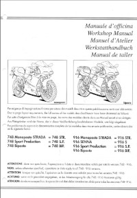
Руководство на английском, немецком, французском, испанском и итальянском языках по ремонту мотоциклов Ducati моделей 748 и 916.
- Издательство: —
- Год издания: —
- Страниц: 484
- Формат: PDF
- Размер: 76,8 Mb
Руководство на английском и итальянском языках по ремонту мотоциклов Ducati моделей 750 SS Desmo, 900 SS Desmo и 900 SD Darmah.
- Издательство: Ducati Meccanica S.p.A.
- Год издания: —
- Страниц: 130
- Формат: PDF
- Размер: 10,3 Mb
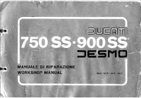
Руководство на английском и итальянском языках по ремонту мотоциклов Ducati моделей 750 SS Desmo и 900 SS Desmo 1975-1977 модельных годов.
- Издательство: Ducati Meccanica S.p.A.
- Год издания: —
- Страниц: 76
- Формат: PDF
- Размер: 11,2 Mb

Руководство на английском и итальянском языках по ремонту мотоциклов Ducati моделей 860 GT и 860 GTS.
- Издательство: Ducati Meccanica S.p.A.
- Год издания: 1976
- Страниц: 198
- Формат: PDF
- Размер: 19,5 Mb
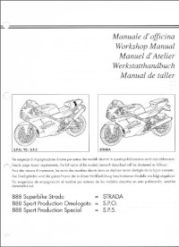
Руководство на английском, французском, немецком, испанском и итальянском языках по ремонту мотоциклов Ducati моделей 888 Strada, 888 SPO и 888 SP5.
- Издательство: Ducati
- Год издания: —
- Страниц: 393
- Формат: PDF
- Размер: 63,7 Mb

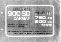
Руководство на английском и итальянском языках по ремонту мотоциклов Ducati модели 900 SD Darmah.
- Издательство: Ducati Meccanica S.p.A.
- Год издания: 1980
- Страниц: 120
- Формат: PDF
- Размер: 10,4 Mb

Руководство на английском и итальянском языках по ремонту мотоциклов Ducati модели 996 1999 модельного года.
- Издательство: Ducati Motor S.p.A.
- Год издания: —
- Страниц: 268
- Формат: PDF
- Размер: 19,7 Mb

Руководство на английском и итальянском языках по ремонту мотоциклов Ducati модели 999R S04 2004 модельного года.
- Издательство: Ducati Corse S.r.L.
- Год издания: —
- Страниц: 268
- Формат: PDF
- Размер: 27,4 Mb
Руководство на английском, французском, немецком, испанском и итальянском языках по ремонту мотоциклов Ducati моделей Alazzurra GT 350 и Alazzurra GT 650.
- Издательство: Ducati Meccanica S.p.A.
- Год издания: —
- Страниц: 181
- Формат: PDF
- Размер: 15,9 Mb

Руководство на немецком языке по техническому обслуживанию и ремонту мотоциклов Ducati моделей M600/750/900 Monster с 1993 года выпуска.
- Издательство: —
- Год издания: —
- Страниц: 91
- Формат: PDF
- Размер: 24,1 Mb

Руководство на английском, французском, немецком, испанском и итальянском языках по ремонту мотоциклов Ducati модели Monster M900.
- Издательство: Ducati
- Год издания: —
- Страниц: 271
- Формат: PDF
- Размер: 43,4 Mb

Руководство на английском и итальянском языках по ремонту мотоциклов Ducati модели Sport Touring ST4 2000 модельного года.
- Издательство: Ducati Motor S.p.A.
- Год издания: —
- Страниц: 257
- Формат: PDF
- Размер: 14,4 Mb

Руководство на английском и итальянском языках по ремонту мотоциклов Ducati модели ST2.
- Издательство: Ducati Motor S.p.A.
- Год издания: —
- Страниц: 247
- Формат: PDF
- Размер: 24,6 Mb

Руководство на английском языке по техническому обслуживанию и ремонту мотоциклов Ducati модели Superbike 848 2008 модельного года.
- Издательство: —
- Год издания: —
- Страниц: 774
- Формат: PDF
- Размер: 80,6 Mb
Руководство на английском языке по техническому обслуживанию и ремонту мотоциклов Ducati моделей Superbike 1098 и Superbike 1098S 2007 модельного года.
- Издательство: —
- Год издания: —
- Страниц: 714
- Формат: PDF
- Размер: 30,7 Mb
Руководство на английском, немецком, французском, испанском и итальянском языках по ремонту мотоциклов Ducati моделей Supersport 750 и Supersport 900 1991-1996 годов выпуска.
- Издательство: Ducati
- Год издания: —
- Страниц: 334
- Формат: PDF
- Размер: 187,6 Mb

Руководство на английском и итальянском языках по ремонту мотоциклов Ducati модели Supersport 900 2001 модельного года.
- Издательство: Ducati Motor Holding S.p.A.
- Год издания: —
- Страниц: 258
- Формат: PDF
- Размер: 37,3 Mb

Руководство на английском языке по техническому обслуживанию и ремонту двигателей Ducati с верхним расположением распредвала 1967-1970 годов выпуска.
- Издательство: Ducati Meccanica S.p.A.
- Год издания: 1969
- Страниц: 20
- Формат: PDF
- Размер: 1,6 Mb
В руководстве представлена информация об устройстве и работе всех узлов и агрегатов мотоцикла.
- Издательство: Алфамер
- Год издания: —
- Страниц: 220
- Формат: —
- Размер: —

- Manuals
- Brands
- Ducati Manuals
- Motorcycle
- Diavel
- Workshop manual
-
Contents
-
Table of Contents
-
Bookmarks
Related Manuals for Ducati Diavel
Summary of Contents for Ducati Diavel
-
Page 2: Table Of Contents
Diavel identification data 3 Section 3 03 — Technical data 1.1 — Technical specifications General 3 Colours 4 Transmission 4 Timing system/valves 5 Crankshaft 5 Cylinder/Piston 6 Gearbox 6 Cooling system 7 Front wheel 7 Front suspension (Diavel ABS) 7…
-
Page 3
1 — General Front suspension (Diavel Carbon ABS) 7 Rear wheel 7 Rear suspension (Diavel ABS) 8 Rear suspension (Diavel Carbon ABS) 8 Hydraulic brakes 8 Charging system/alternator 9 Injection-ignition system 9 Fuel system 9 Injection system 9 Lights/instrument panel 10 1.2 — Dimensions… -
Page 4
1 — General Adjusting the throttle cable 41 Adjusting the clutch lever and front brake lever 43 Adjusting the position of the gear change and rear brake pedals 44 Adjusting the front fork 45 Adjusting the rear shock absorber 47 Section 5 05 — Fairings 1 — Rear-view mirrors… -
Page 5
1 — General Table D 15 Table E 17 Table F 19 Table G 20 Table H 21 Table J 23 Table K 24 Table L 25 Table M 26 Table N 27 Table O 29 Table P 31 Table Q 32 Table R 33 Table S 38 Table T 39… -
Page 6
Dashboard diagnosis 111 “Setting” menu 113 “Riding Mode” customisation 115 DTC (Ducati Traction Control) setting function 117 Tips on how to select the sensitivity level 118 ENGINE setting function (Engine Power Control) 119 DEFAULT function (Resetting Ducati default parameters) 120… -
Page 7
1 — General Recovery procedure in the event of electric steering lock fault 145 Recovery procedure in the event of Hands Free system fault 146 Start procedure with PIN code (no keys) 146 How to enable engine start with PIN code 147 How to enable the PIN code 147 How to reset the PIN code 147 Wiring diagram of the Hands Free system 148… -
Page 8
1 — General High beam flash not working — start/stop lap function not working 244 Number plate light not working 245 Running lights not working 246 Dashboard menu option scrolling not possible 247 Resetting turn indicators not possible — accessing dashboard menu not possible 248 Gear indicator display on dashboard shows dashes, engaged gear not displayed correctly, idle speed irregular with gearbox in neutral. -
Page 9
1 — General 4 — Rear brake Removing of the rear brake control 32 Disassembly of the rear brake control 34 Refitting the rear brake control 35 Removal of the rear brake calliper 39 Removal of the rear brake disc 40 Refitting the rear brake calliper 41 5 — ABS system information Operating principle 42… -
Page 10
1 — General Steering angle adjustment 109 Removal of the steering head components 110 Refitting the steering head components 114 12 — Rear shock absorber assembly Rear suspension system 121 Removal of the rear shock absorber 122 Overhauling the rear shock absorber 123 Disassembly of rear shock absorber — rocker arm — linkage assembly 123 Reassembly of rear shock absorber — rocker arm — linkage assembly 124 Refitting the rear suspension 128… -
Page 11
1 — General Section 8 08 — Fuel/Exhaust System 2 — Fuel tank Removal of the fuel tank 4 Removal of the fuel tank filler cap 6 Refitting the filler cap 7 Replacing the tank flange and fuel sensor. 8 Refitting the fuel tank flange 9 Refitting the fuel tank 9 6 — Airbox –… -
Page 12
1 — General Refitting the expansion tank 25 Removal of the cooling system hoses and unions 30 Refitting the cooling system hoses and unions 33 3.2 — Cooling system: water radiators Removing the water radiators 47 Disassembling the water radiator unit 50 Renewal of the cooling fan 52 Reassembling the water radiator unit 53 Refitting the radiator 58… -
Page 13
1 — General Checking and overhauling the components 154 Reassembling the clutch 156 6.2 — Clutch assembly: clutch cover Removal of the clutch-side crankcase cover 161 Disassembly of the clutch cover 162 Reassembly of the clutch-side crankcase cover 163 Refitting the clutch-side crankcase cover 164 6.3 — Clutch assembly: primary drive gears Removal of the primary drive gear 166 Refitting the primary drive gears and checking backlash 168… -
Page 14: General
1 — General Refitting the crankshaft/connecting rod assembly 274…
-
Page 15
1 — Impianto elettri-co 01 — Impianto elettrico 1 — How to use this manual How to use this manual 3 Layout of the manual 4 2 — Symbols — Abbreviations — References Product specifications 6 3 — Hazardous Products — Warnings General safety rules 8 General maintenance indications 10… -
Page 16: How To Use This Manual
This manual also describes the essential checks to be carried out prior to delivery of the motorcycle. Ducati Motor Holding S.p.A. declines all liability for any technical errors or omissions in this manual and reserves the right to make changes made necessary by the technical evolution of its products without prior notice.
-
Page 17
Important The structure of the manual has been designed so that all the models types of the DUCATI MOTOR HOLDING products can be included. To facilitate consultation of the manual, the table of contents is identical for all motorcycle models. -
Page 18: Symbols — Abbreviations — References
Symbols — Abbreviations — References 2 -Symbols — Abbreviations — References To allow quick and easy consultation, this manual uses graphic symbols to highlight situations in which maximum care is required, as well as practical advice or information. Pay attention to the meaning of the symbols since they serve to avoid repeating technical concepts or safety warnings throughout the text.
-
Page 19
Medium-strength threadlocker Loctite 401 LOCK 12 Instant adhesive gel offering tensile/shear strength. Loctite 454 gel DUCATI fluid gasket. 942470014 Exhaust pipe paste. Self-sealing paste, hardens when Holts Firegum heated; resists temperatures exceeding 1000 °C. Spray used to protect electric systems. -
Page 20
Symbols — Abbreviations — References Emulsion for lubrication of rubber. P 80… -
Page 21: Hazardous Products — Warnings
Hazardous Products — Warnings 3 -Hazardous Products — Warnings General safety rules Carbon monoxide When a maintenance operation must be performed with the engine running, maker sure that the working area is well- ventilated. Never run the engine in an enclosed space. Warning Exhaust fumes contain carbon monoxide, which is a poisonous gas that can cause unconsciousness or even death if inhaled.
-
Page 22: General Maintenance Indications
General maintenance indications Useful tips Ducati recommends that you follow the instructions below in order to prevent problems and obtain the best end result: — when diagnosing faults, primary consideration should always be given to what the customer reports about motorcycle operation since this information can highlight anomalies;…
-
Page 23: Identification Data
2 — Impianto elettrico 02 — Impianto elettrico 1 — Identification data Diavel identification data 3…
-
Page 24: Diavel Identification Data
Identification data 1 -Identification data Diavel identification data Each Ducati motorcycle has two identification numbers -the frame number and the engine number- and an EC nameplate (A) (NOT PRESENT ON THE US VERSION). Note Please quote these numbers, which identify the motorcycle model, when ordering spare parts.
-
Page 25
Identification data 1 Manufacturer: Ducati Motor Holding 2 Type — same for all Diavel / Diavel Carbon models 3 Variant 4 Version: AA = Diavel / Diavel Carbon AB = Diavel ABS / Diavel Carbon ABS 5 Year of manufacture:… -
Page 26
3 Variant – Numeric or X (Check digit) 4 Model year (A=2011) 5 Manufacturing facility 6 Progressive serial No. Data stamped on engine Europe version 1 Manufacturer: Ducati Motor Holding 2 Engine type 3 Progressive production No. Data stamped on engine US version 1 Engine type 2 Model year (B=2011) 3 Progressive production No. -
Page 27
Cylinder/Piston 6 Gearbox 6 Cooling system 7 Front wheel 7 Front suspension (Diavel ABS) 7 Front suspension (Diavel Carbon ABS) 7 Rear wheel 7 Rear suspension (Diavel ABS) 8 Rear suspension (Diavel Carbon ABS) 8 Hydraulic brakes 8 Charging system/alternator 9… -
Page 28: Technical Specifications
Rear wheel travel: 120 mm Shock absorber stroke: 50 mm Front wheel rim (Diavel ABS) Light alloy with 14 spokes. Front wheel rim (Diavel Carbon ABS) Forged in light alloy with 9 spokes. Front wheel size MT 3.50×17” Front tyre size…
-
Page 29: Colours
57E22714 (AKZO) Enamel 54M22705 (AKZO); Clear lacquer 228.880 (PPG) Racing Black frame and black wheel rims. Diavel Carbon ABS Red and Mat Carbon Ducati red enamel 54D234015 (AKZO) Red frame and black rims. Glossy and Matt Carbon; Pearl White Silk enamel 53E23102 (AKZO);…
-
Page 30: Crankshaft
Technical specifications Closing rocker arm — intake 0.05-0.10 mm 0.05 to 0.15 mm Closing rocker arm — exhaust 0.05-0.10 mm 0.05 to 0.15 mm Reference Adjusting clearance Reset value (new belt) (used belt) 110±5 Hz (horizontal) 80±5 Hz (horizontal) Belt tensioning when cold 110±5 Hz (vertical) 80±5 Hz (vertical) Limit minimum value with cold…
-
Page 31: Cooling System
Fork leg Ø 50 mm Travel along leg axis 120 mm Oil charge per fork leg 720 cm 2 (per leg) Front suspension (Diavel Carbon ABS) Reference Technical specifications MARZOCCHI: Type Upside-down fork with DLC coating, adjustable compression, rebound and spring preload.
-
Page 32: Rear Suspension (Diavel Abs)
Rear wheel travel: 120 mm Shock absorber stroke: 50 mm Stroke 50 mm Shock absorber Rear suspension (Diavel Carbon ABS) Reference Technical specifications SACHS: Type The rear suspension system uses a hydraulic monoshock absorber with rebound, compression and spring preload adjustment.
-
Page 33: Charging System/Alternator
Technical specifications Calliper cylinder diameter 30 mm / 32 mm Pad friction material TT2182 FF Type PS13 Cylinder Master cylinder diameter 13 mm Charging system/alternator Reference Technical specifications Voltage 12 V Battery Capacity 10 Ah Type Sealed, maintenance free Capacity 12 V — 430 W Generator Injection-ignition system…
-
Page 34
Technical specifications ABS 2 25 A ABS 1 30 A Fans 10 A Diagnosis / Recharge 7.5 A… -
Page 35: Dimensions
Dimensions 1.2 -Dimensions…
-
Page 36: Fuel, Lubricants And Other Fluids
Fuel, lubricants and other fluids 2 -Fuel, lubricants and other fluids Fuel, lubricants and other fluids Type Quantity (litres) Unleaded fuel with 95 fuel octane rating Fuel tank, including a reserve of 4 dm 17 dm (litres) (at least) 16 dm (litres) (USA) Lubrication circuit…
-
Page 37: Torque Settings
Torque settings 3 -Torque settings Frame torque settings Part Thread (mm) Nm ±10% Note Tolerance Top fairing Right rear-view mirror retaining screw M8x1.25 Left rear-view mirror retaining screw M8x1.25 Stand Side stand plate retaining screw on shock absorber M10x1.5 support Stand sensor screw M6x1 Front sprocket…
-
Page 38
Torque settings retaining screw Electrical components cover — electrical components M6x1 solid threadlocker on support retaining screw screw Horn to battery support retaining screw M8x1.25 Voltage regulator to clip on electrical components M6x1 support retaining screw Hands free switch retaining screw M6x1 LOCK 2 Hands free switch retaining nut… -
Page 39
Torque settings Shock absorber to rocker arm retaining screw M10x1.25 Rocker arm to swingarm retaining screw M10x1.25 Front mudguard Mudguard to fork calliper retaining screw M6x1 solid threadlocker on screw Front brake pipe clip on mudguard retaining screw AF3.5 0.35 Fluid cooling Fan to fan support retaining screw M4x0.7… -
Page 40
Torque settings underside) Rear wheel cush drive bush retaining nut M10x1 LOCK 2 Phonic wheel to disc fixing screw M5x0.8 solid threadlocker on screw Brake disc to pin fixing screw M8x1 Fuel tank Tank to frame retaining screw M6x1 Bitron flange to tank retaining screw M5x0.8 Solid threadlocker on screw… -
Page 41: Engine Torque Settings
Torque settings Air intake oil breather Wiring protection on airbox lower half-housing M5x0.8 Oval intake funnel on airbox lower half-housing M5x0.8 retaining screw Conveyors to airbox retaining screw M5x0.8 Map sensor bracket to airbox upper half housing M6x1 retaining screw Air temperature sensor to LH conveyor retaining screw M4x0.7 Map sensor on bracket retaining screw M6x1…
-
Page 42
Torque settings Preload torque Tightening torque 22.5 Coil retaining screw M6x1 Pulley flange retaining screws M6x1 Cylinder head cover screw M6x1 Exhaust manifold stud M6x1 LOCK 5 Vacuum gauge connection screw on cylinder M6x1 LOCK 2 or TB1324 head (EU only) Evaporative emissions canister fitting on M6x1 LOCK 2 or TB1324… -
Page 43
Torque settings Selector claw locator nut M6x1 Selector claw screw M6x1 LOCK 2 or TB1324 Idler and tensioner pulley bolts M20x1 LOCK 2 or TB1324 Timing belt driveshaft pulley retaining nut M15x1 GREASE A Timing belt driveshaft gear nut M14x1 GREASE A Fixed tensioner bearing locking screw M14X2… -
Page 44: Service Tools
Diavel_Carbon_11_3_4.13.1.html 4 -Service tools Spare parts catalogue Diavel ABS WORKSHOP SERVICE TOOLS Diavel ABS WORKSHOP SERVICE TOOLS Diavel Carbon WORKSHOP SERVICE TOOLS Diavel Carbon WORKSHOP SERVICE TOOLS Specific tools for the engine Code no. Description 88713.2011 Tool to lock crankshaft at Top Dead Centre 88713.2676 Wrench for tightening cylinder head nuts…
-
Page 45
Diavel_Carbon_11_3_4.13.1.html 88713.3521 Gearbox output shaft oil seal installer 88713.1806 Holding tool for pulley tightening 97900.0215 DDS (Ducati Diagnosis System) + cylinder vacuum meter kit 88765.1518 Valve lift gauge 88713.2878 Fork-type feeler gauge 0.2 mm, 0.3 mm 88713.3367 Flywheel tool 88713.1920 Tool for installing O-rings on crankcase studs… -
Page 46
Diavel_Carbon_11_3_4.13.1.html 88713.3334 Plate for gear selector fork positioning 88713.2442 Tool for installation of sealing ring on valve-guide 88713.1749 Puller for drive pulley and cover 88713.1832 Engine repair bench 88713.3408 Wet FCC clutch drum holding tool 88765.1623 Distribution pulley timing tool 88713.1886 Engine cover sheet 88713.1010 Exhaust gases pick-up connector… -
Page 47
Diavel_Carbon_11_3_4.13.1.html 88713.1805 Tool for tightening timing belt driveshaft pulley 88765.2090 Top Dead Centre test gauge 88713.3219 Holding tool for pulley tightening 88713.0869 Water pump front seal installer 88713.0870 Installation tool for counter plate for water pump front seal 88700.5749 Crankcase half assembly cap 88713.2877 Spark plug wrench 88713.1980 Punch for installing caps on shafts… -
Page 48
Diavel_Carbon_11_3_4.13.1.html 88713.3497 Timing belt tensioner pulley wrench 88765.1298 Spacer lower register control valve 88713.2870 Connecting rod guide tool 88713.3394 Punch to install circlip on the camshaft 88713.3406 Wrench for tightening primary sprocket nut 88713.2906 Oil filter cartridge wrench 88713.3417 Torque wrench for tightening front sprocket nut 88713.3407 Bush (gear position sensor) -
Page 49: Specific Tools For The Frame
88713.0944 Oil filter cartridge wrench 88713.2834 Circlip fitting punch 88713.1994 Rocker arm shaft puller 88713.3734 Timing belt tensioner pulley wrench Spare parts catalogue Diavel ABS WORKSHOP SERVICE TOOLS Diavel Carbon WORKSHOP SERVICE TOOLS Specific tools for the frame Code no.
-
Page 50
Diavel_Carbon_11_3_4.13.1.html 88713.2562 Chain assembly tool 88713.1058 Wrench for steering shaft nut 88713.1062 Tool for installing steering head bearings 88713.2951 Rear wheel balancing tool 88713.3211 Wrench for adjustment of the eccentric hub 88713.3204 MARZOCCHI fork service tool — Sealing ring fitting 88713.3203 Pull bar for MARZOCCHI fork service… -
Page 51
88713.2409 Swingarm ball bearing installation tool 88713.3526 Frame plates assembling wrench 88713.3396 Engine repair bench 8000.70139 Front wheel shaft wrench 88713.1515 Engine/frame support Spare parts catalogue Diavel ABS DDS TESTER Diavel ABS WORKSHOP SERVICE TOOLS Diavel Carbon DDS TESTER Diavel Carbon… -
Page 52: Appropriate Diagnosis Tools
Diavel_Carbon_11_3_4.13.1.html WORKSHOP SERVICE TOOLS Appropriate diagnosis tools Code no. Description 97900.0211 DDS (Ducati Diagnosis System) without cables 97900.0227 Power cable and diagnosis 97900.0222 Power cable and diagnosis 1060838 (Measurement Module) 97900.0218 Vacuum sensor 552.1.039.1A Pressure sensor 97900.0220 Pressure/vacuum tube 97900.0221 Union…
-
Page 53
Diavel_Carbon_11_3_4.13.1.html 97900.0228 Battery socket adapter 814.1.114.1A Oil pressure coupling 514.1.032.1A Auxiliary test cable 552.1.038.1A Cylinder compression cable M10 fitting 875.1.065.1A Oil pressure tube 97900.0230 Feeder 97900.0224 Feeder 88765.1371 Belt tensioning sensor… -
Page 54
Diavel_Carbon_11_3_4.13.1.html 88765.1374 Belt tensioning sensor bracket 590.1.189.1A Fuel pressure tube 88765.1126 Clamp-type amperemeter 97900.0227S CAN network diagnosis cable… -
Page 55: Maintenance Operations
4 — Impianto elettrico 04 — Impianto elettrico 1 — Vehicle pre-delivery 2 — Scheduled maintenance chart Operations to be carried out by the dealer 4 List of operations to be performed at 1000 km 4 Operations to be carried out by the dealer 5 List of operations to be performed every 12000 km / year (first limit reached) 5 Operations to be carried out by the customer 5 List of operations to be performed every 1000 km 5…
-
Page 56: Vehicle Pre-Delivery
Vehicle pre-delivery 1 -Vehicle pre-delivery 1 Transport packaging integrity check (if required); 2 Removal from the transport packaging (if required); 3 Motorcycle integrity check; 4 Check of the supplied kit completeness (refer to the parts list supplied together with the bike packaging); 5 Only if the bike is supplied in a crate: handlebar and controls assembly;…
-
Page 57: Scheduled Maintenance Chart
Scheduled maintenance chart 2 -Scheduled maintenance chart Operations to be carried out by the dealer List of operations to be performed at 1000 km Reading of the error memory with DDS on the engine control units, vehicle and ABS Change the engine oil Change the engine oil filter Check the indicators and lighting Check the safety devices (side stand switch, clutch lever switch, right switch engine stop switch and gear…
-
Page 58: Operations To Be Carried Out By The Customer
Scheduled maintenance chart Replace the air filter (only every 24000 km) Replace the front fork oil (only every 24000 km) Replace the coolant (only every 24000 km) Check the indicators and lighting Check the safety devices (side stand switch, clutch lever switch, right switch engine stop switch and gear position sensor) Check the battery charge level Checking the coolant level…
-
Page 59: Maintenance Operations
Maintenance operations 3 -Maintenance operations Reading of the error memory with DDS on the engine control units, vehicle and ABS Check if there are errors by following the procedure described in the paragraph “Guided diagnosis” (Sect. 6 — 11). Check engine oil level Check the engine oil level through the sight glass (1) on the right-hand side of the oil sump.
-
Page 60
Maintenance operations Tighten the exhaust plug (3) to a torque of 20 Nm (Min. 18 Nm — Max. 22 Nm) (Sect. 3 — 3, Engine torque settings). Remove the oil sump filter cartridge (4) using service tool 88713.2906. Important Dispose of the used cartridge, do not attempt to reutilise it. Fit a new cartridge (4), using the tool 88713.2906 making sure to lubricate the gasket with engine oil. -
Page 61
Maintenance operations Remove the filtering element (7) and check the O-rings (8) and (9), replace them if necessary. Clean the filter with petrol and compressed air. Take care not to damage the gauze. Place the O-ring (9) on the crankcase and the (8) one on the mesh filter (7). -
Page 62
Maintenance operations Refit the mesh filter (7). Apply a bead of fluid gasket to the cap (6) as shown in the figure. Remove the filler plug (2) and carry out refilling with the specified oil type (Sect. 3 — 2, Fuel, lubricants and other fluids) up to reaching the notch that identifies the MAX level in the sight glass (1). -
Page 63: Checking Valve Clearances
Maintenance operations Checking valve clearances To check the valves clearance, it is necessary to have access to the cylinder head covers and then remove the components listed below. Operations Section reference Remove the saddles 5 — 3, Removal of the seat Remove air conveyor covers 8 — 7, Removal of the air filters…
-
Page 64
Maintenance operations Opening rocker arm INTAKE: Operation 0.13 to 0.18 mm Checking clearance 0.10 to 0.25 mm EXHAUST: Operation 0.13 to 0.18 mm Checking clearance 0.10 to 0.25 mm With the valve in the rest position, slide a feeler gauge between closing rocker arm (C) and the highest side of the cam (D) to measure the clearance. -
Page 65
Maintenance operations If detected values exceed the specified limits, replace opening and/or closing shims, as described in paragraph “Removing valves” (Sect. 9 — 4.5), with an adequate height to obtain the specified clearance. Note Opening rocker arm shims measuring from 1.8 to 3.45 mm and closing rocker arm shims measuring from 2.2 to 4.5 are available as spare parts. -
Page 66: Change Timing Belts
Maintenance operations Refit the cylinder head cover 9 — 4.4, Refitting the camshafts Refit the coils 6 — 9, Ignition coils Refit the exhaust unit 8 — 8, Refitting the exhaust system Fasten the timing belt covers 9 — 4.2, Refitting the timing covers Reassemble the water radiators on 9 — 3.2,…
-
Page 67
Maintenance operations Remove the tank covers 5 — 2, Removal of the fuel tank fairings Remove the fuel tank 8 — 2, Removal of the fuel tank Remove the coil-spark plugs wires (1), loosening the screws (2) of both spark plugs. Using the appropriate tool 88713.2877 to replace the spark plugs. -
Page 68
Maintenance operations Changing and cleaning the air filters The air filter must be replaced at the intervals described in the “Scheduled maintenance chart” (Sect. 4 — 2). Operations Section reference Refit the seat 5 — 3, Refitting the seat Remove the tank covers 5 — 2, Removal of the fuel tank fairings… -
Page 69
Maintenance operations tab (B) of the gasket (6) matches with slot (C) of the RH conveyor (2) as shown in the figure. Note Check for no abnormal wrinkles during gasket fitting. Start the screws (1) and screw (3) with washer (4). Tighten the screws (1) to a torque of 3.5 Nm ±… -
Page 70
Maintenance operations Loosen the screws (11) fixing the horizontal belt timing cover (7) and remove it from the horizontal cylinder assembly. Loosen the screws (12) and remove the filter (10). Apply the recommended threadlocker to the screws (8) and (11). Once the check has been carried out refit filter (10), screw without tightening the screws (12) and refit the horizontal timing belt cover (7) on the horizontal cylinder assembly by tightening the screws (11) to a torque of 10 Nm (Min. -
Page 71
Maintenance operations For optimal operating conditions (coolant mixture starting to freeze at -20 °C), the recommended fluid antifreeze should be mixed with water in the following percentages: ANTIFREEZE: 35 to 40% of the volume; WATER: 65 to 60% of the volume. Important Very hard water with a high mineral salt content can damage the engine. -
Page 72
Maintenance operations Loosen the cap (4) of the fluid exhaust hole placed on the pump cover. Allow the coolant to drain off completely. Screw plug (4) with a seal again in the fluid drain hole, and recover the new seal (5). Tighten the plug (4) to a torque of 20 Nm (Min. -
Page 73
Maintenance operations Important Check the cooling circuit for possible leaks. Top up the coolant through the expansion reservoir filler to bring the level up to the MAX. mark. Tighten the cap (1) of the expansion reservoir. Operations Section reference Reassemble the RH intake duct 8 — 7, Refitting the air filters Reassemble the RH front half-… -
Page 74
Maintenance operations Once that all pistons of both callipers are fully moved back and that all the fluid in the tank has been aspirated, connect to the bleed valve (5) a transparent tube by immersing the end in a container placed on the floor. Fill the reservoir (2) with new brake fluid up to the MAX. -
Page 75
Maintenance operations Tighten the bleed valve (5) to a torque of 23 Nm ±10% (Sect. 3 — 3, Frame torque settings) then release the lever. Repeat the operation described above until the old fluid flows completely. Then, with the bleed valve definitely closed to the specified torque actuate repeatedly the lever until a pressure is detected in the brake system. -
Page 76
Maintenance operations Unscrew the cap (6) of the rear brake fluid reservoir (7). Siphon off the fluid from the reservoir (7). Fill the reservoir (7) with new brake fluid up to the MAX. mark. Press the pedal to allow the circuit to go under pressure. Keep the pedal pressed to the bottom. -
Page 77
Maintenance operations Apply the recommended threadlocker on the screw (C). Refit pipe grommet (B) and tighten the screw (C) to a torque of 4 Nm ±10% (Sect. 3 — 3, Frame torque settings). Lock the rear brake hose, the tail light wiring and the speed sensor by means of the new ties (A). Fit the rear brake calliper (10) over the brake disc, aligning it with the holes in the calliper mounting bracket. -
Page 78
Maintenance operations placed on the floor. Open the bleed valve (4) to allow fluid to escape. Warning During the filling operation, always keep the oil level above the MIN mark to prevent the formation of air bubbles in the circuit. Allow the fluid to flow from the bleed valve (4) until it changes colour. -
Page 79
Maintenance operations Unscrew the bleed valve by a 1/4 turn. Operate the clutch lever until all the fluid has been expelled. To completely empty the circuit it is advisable to remove the cap of clutch recover. Undo the screws (5) and slide out the clutch slave cylinder (6). Push in the internal piston (A) to force out all the fluid from inside the cap. -
Page 80
Maintenance operations Turn the clutch pushrod (7) counter clockwise until the hole axis of the anti-rotation pin (8) is aligned with the centreline of the casing cover machined surface (D), as shown in the figure. Insert the clutch actuator (6) into the pushrod (7) and bring it fully home on the anti-rotation insert (9). Note Upon insertion of the clutch actuator (6), make sure that the tab (C) of insert (9) matches with the actuator slot (E). -
Page 81
Maintenance operations Fill the tank with specified oil (Sect. 3 — 2, Fuel, lubricants and other fluids) taken from an intact container. Important During the following operation, the fluid level must remain topped up at all times. The end of the transparent plastic tubing must remain immersed in the discharged fluid at all times. -
Page 82
Maintenance operations Top up the fluid level to approximately 3 mm above the MIN mark of the tank. Reassemble cover (1) and membrane from the clutch fluid reservoir (2) by tightening the screws (3). Adjusting the steering head bearings Excessive handlebar play or shaking forks in the steering head indicate that the play in the steering head bearings requires adjustment. -
Page 83
Maintenance operations Adjusting the chain tension Make the rear wheel turn until you find the position where chain is tightest. Set the vehicle on the side stand. Push down the chain at the point of measurement and release. Measure the distance between the “aperture” upper profile and pin centre. -
Page 84
Maintenance operations Checking brake pad wear and changing brake pads Warning Brake fluid is corrosive and will damage paintwork. Avoid contact with eyes and skin. In the case of accidental contact, wash the affected area thoroughly with plenty of running water. Important On handing over the motorcycle after changing the brake pads, inform the customer that the front brake must be used gently for the first 100 km to allow the pads to bed in completely. -
Page 85
Maintenance operations Top-up with specified fluid (Sect. 3 — 2, Fuel, lubricants and other fluids) until reaching the MAX notch. Hold the lever pulled towards the handgrip and simultaneously tighten the calliper screws (1) to a torque of 43 Nm ±10%(Sect. -
Page 86
Maintenance operations Force the brake pads apart to push the calliper pistons into their housings. Release the worn pads (5) from the spring (6). Insert the new pads (5) and the clip (6). Slide in the pad retaining pin (3) and secure it in position with the safety cotter pin (2). Force the pads apart to push the calliper pistons into their housings. -
Page 87
Maintenance operations Operate the brake pedal repeatedly so that the pads are bedded in against the disc by the force of the brake fluid. Check that the brake fluid level in the tank is between the MIN and MAX. marks. If this is not the case, act on to the top- up after unscrewing the tank cap (6). -
Page 88
Maintenance operations Adjuster (1) adjusts the throttle opening control, while adjuster (2) adjusts the throttle closing control. Note The throttle cables are distinguished by the writings in different colours on them: — on the throttle opening cable (1) is a white writing; — on the throttle closure cable (2) is a yellow writing. -
Page 89
Maintenance operations Place the covers (5) and (6) in the reference hole of the handlebar. Fix covers (5) and (6) by tightening the screws (7) to a torque of 10 Nm ± 10% (Sect. 3 — 3, Frame torque settings). Adjusting the clutch lever and front brake lever The clutch lever (1) is fitted with a span adjuster (2) which serves to alter the distance of the lever from the handlebar. -
Page 90
Maintenance operations Adjusting the position of the gear change and rear brake pedals The position of the gear change and rear brake pedals in relation to the footrests can be adjusted to suit the preferred riding position. To modify the gear change pedal position act in the following mode: hold the linkage (1) and slacken the counter nuts (2) and (3). -
Page 91
Maintenance operations 3) compression damping. Park the motorcycle in a stable position on its side stand. Turn the adjuster (1) on fork leg top with a flat screwdriver to adjust rebound damping. On the Carbon model, adjustment is done using the knob (B) on the fork leg, without a screwdriver. Turn the adjuster (3) on fork leg bottom with a flat screwdriver to adjust compression damping. -
Page 92
Maintenance operations Turn the adjuster (1) clockwise to increase damping H; or counter clockwise to reduce damping S. STANDARD setting from the fully closed position (clockwise): — unscrew adjuster (1) by 8 clicks. Spring preload: 15 mm. The two nuts (2) on the upper part of the shock absorber serve to adjust the preload on the external spring. To change spring preload, slacken the upper locking ring nut. -
Page 93
Maintenance operations If the motorcycle is to be ridden with a pillion rider and luggage, we recommend setting the rear shock absorber spring preload to the maximum to ensure the best handling and proper ground clearance at all times. It may also be necessary to adjust the rebound damping accordingly. -
Page 94
5 — Impianto elettrico 05 — Impianto elettrico 1 — Rear-view mirrors Removal of the rear-view mirrors 4 Refitting the rear-view mirrors 4 2 — Fairings Removal of the fuel tank fairings 6 Disassembly of the front half-fairings 9 Reassembly of the front half-fairings 10 Refitting the fuel tank fairings 12 3 — Seat Removal of the seat 20… -
Page 95: Rear-View Mirrors
1 Rear-view mirror 2 Screw 3 U-bolt 4 Spring washer Spare parts catalogue Diavel ABS HANDLEBAR AND CONTROLS Diavel Carbon HANDLEBAR AND CONTROLS Important Bold reference numbers in this section identify parts not shown in the figures alongside the text, but which can be found in the exploded view diagram.
-
Page 96: Refitting The Rear-View Mirrors
Rear-view mirrors Refitting the rear-view mirrors Start the screws (2) in their thread on the rear-view mirrors (1), inserting the washers (4) as shown in the picture. Insert the rear-view mirrors (1) in the U-bolts (3). Tighten the screws (2) to a torque of 25 Nm ±10% (Sect. 3 — 3, Frame torque settings).
-
Page 97: Fairings
14 Screw 15 Nylon washer 16 Special screw 17 Washer 18 Spacer 19 Spring 20 Rubber pad 21 RH tank fairing 22 Tank fairing 23 Tank plug cover 24 Spacer 25 Screw Spare parts catalogue Diavel ABS FAIRING Diavel Carbon FAIRING…
-
Page 98: Removal Of The Fuel Tank Fairings
Fairings Important Bold reference numbers in this section identify parts not shown in the figures alongside the text, but which can be found in the exploded view diagram. Removal of the fuel tank fairings Operations Section reference Remove the seat Sect.
-
Page 99
Fairings Loosen the screws (16) and (25) securing the tank plug cover (23) but do not remove it. Lift the tank plug cover (23) up in order to reach the wiring (E) of the dashboard (F). Disconnect the wiring (E) from the dashboard (F). -
Page 100
Fairings Remove the tank plug cover (23) from the vehicle recovering the screws (25) and spacers (24). Remove the LH tank fairing (21) by loosening screws (16) and (14); recover the washers (17) and (15). Remove the RH tank fairing (13) by loosening screws (16) and (14); recover the washers (17) and (15). Remove the tank fairing (22) by loosening the screws (14);… -
Page 101: Disassembly Of The Front Half-Fairings
Fairings Disassembly of the front half-fairings Undo the screws (5) and separate the RH support (4) from the front right half-fairing (1). Follow the same procedure to disassemble the LH half-fairing (12). Reassembly of the front half-fairings Fit the clips (2) on the front RH half-fairing (1). Join the RH support (4) and the front RH half-fairing (1) and keep them in position by starting the screws (5).
-
Page 102: Refitting The Fuel Tank Fairings
Fairings Tighten the screws (5) to a torque of 5 Nm ± 10% (Sect. 3 — 3, Frame torque settings). Fit the clips (10) on the front RH half-fairing (1). Follow the same procedure to reassemble the LH half-fairing (12). Refitting the fuel tank fairings Make sure that the following components are fitted on the tank fairing (22): — spacers (18);…
-
Page 103
Fairings Apply threadlocker to the screws (14). Place the tank fairing (22) on the tank and keep it in position by starting the screws (14) together with the relevant nylon washers (15). Tighten to torque of 2 Nm ±10% (Sect. 3 — 3, Frame torque settings) the screws (14). -
Page 104
Fairings Fit the tank RH fairing (13) and keep it in position by starting the screws (16) together with the relevant washers (17). Apply some threadlocker on the screw (14), fit the nylon washer (15) and start the screw. Tighten the screw (14) to a torque of 2 Nm ± 10% (Sect. 3 — 3, Frame torque settings) and the screws (16) to a torque of 0.33 Nm ±10% (Sect. -
Page 105
Fairings Place the tank plug cover (23) on the vehicle and connect connector (E) to the dashboard (F); push connector until an audible click indicates proper engagement. Apply threadlocker to the screws (25). Fit the tank plug cover (23), fit spacers (24), and start screws (25) and screws (16). Tighten the screws (25) to a torque of 2 Nm ±… -
Page 106
Fairings Lubricate the seals (D) of the central tank cover (22) using lubricant specific for rubber. Position the front RH half-fairing (1) by inserting the tabs (C) into the seals (D) pushing downwards (blue arrows); after that, slide the half-fairing completely to the rear side of the motorcycle (red arrows). Block the front RH half-fairing (1) by forcing pin (A) into the receptacle (B) in the RH water radiator. -
Page 107
Fairings Fix the front RH half-fairing (1) by tightening the screw (3) to a torque of 0.33 Nm ± 10% (Sect. 3 — 3, Frame torque settings). Follow the same procedure to reassemble the LH half-fairing (12). Apply threadlocker to the screws (9). Fit the RH air inlet (7) and fix it to the tank plug cover (23) by starting the screws (6) and (9). -
Page 108
Fairings Operations Section reference Reassemble the handlebar Sect. 6 — 7, Dashboard dashboard Refit the seat Sect. 5 — 3, Refitting the seat… -
Page 109: Seat
3 Rubber mounting 4 Special screw 5 Plate 6 Latch Spare parts catalogue Diavel ABS SEAT Diavel Carbon SEAT Important Bold reference numbers in this section identify parts not shown in the figures alongside the text, but which can be found in the exploded view diagram.
-
Page 110: Disassembly Of The Seat
Seat Disassembly of the seat Remove the seat and turn it upside down. Loosen the special screws (4), turn the plates (5) and open the seat cover (2) lateral sides to slide it out. Reassembly of the seat Place the seat cover (2) on the seat and fix it (on the lower side) by starting screws (4) on plates (5). Tighten the screws (4) to a torque of 4 Nm ±…
-
Page 111: Refitting The Seat
Seat Refitting the seat Note Apply recommended grease to the hole (A) of latch (6). Fit the seat (1) as follows: insert the tabs (B) (on the front side) under the rubber pads (C) of the gloves compartment; then push the seat rear side until hearing the lock latch click.
-
Page 112
Seat… -
Page 113: Front And Rear Mudguard
2 Washer 3 Rivet 4 Clip 5 Screw 6 Spacer 7 Screw 8 Rear mudguard 9 Screw Spare parts catalogue Diavel ABS REAR SWINGARM Diavel ABS BELLY FAIRING Diavel Carbon REAR SWINGARM Diavel Carbon BELLY FAIRING Important Bold reference numbers in this section identify parts not shown in the figures alongside the text, but which can be found in the exploded view diagram.
-
Page 114
Front and rear mudguard Undo and remove the special retaining screws (5): keep the spacers (6). Remove the front mudguard (1). Warning The version provided with carbon mudguards features nylon washers instead of the spacers (6). Note On USA versions, a reflector is mounted on the front mudguard (1). Note The hose grommet (4) is fastened to front mudguard (1) by means of a shear rivet (3) with two washers (2) in-between. -
Page 115: Refitting The Front Mudguard
Front and rear mudguard Refitting the front mudguard Warning Do not use the motorcycle without the front mudguard fitted to avoid the risk of the brake pipes fouling the wheel on braking. Insert the screws (5) in spacers (6) with recommended threadlocker, as shown in the figure. Position the front mudguard (1) and start the special screws (5).
-
Page 116: Removing The Rear Mudguard
Front and rear mudguard Place the hose grommet (A) of the front brake hose and the speed sensor cable inside clip (4) as shown in the figure. Frame torque settings). Close the clip (4) and tighten the screw (7) to a torque of 0.35 Nm ± 10% (Sect. 3 — 3, Removing the rear mudguard Undo the screws (9) and remove the rear mudguard (8) from the swingarm.
-
Page 117
Front and rear mudguard… -
Page 118: Belly Fairing
11 Clip 12 Screw 13 Bracket 14 Screw Spare parts catalogue Diavel ABS BELLY FAIRING Diavel Carbon BELLY FAIRING Important Bold reference numbers in this section identify parts not shown in the figures alongside the text, but which can be found in the exploded view diagram.
-
Page 119
Belly fairing Remove the LH belly fairing (2) by loosening the screws (3) with relevant washers (4) and the screws (12). Follow the same procedure to remove the RH belly fairing (1). -
Page 120
Belly fairing Loosen the screws (14) and remove the bracket (13 from the electrical components support. Remove the oil cooler shield (7) from the electrical components support (S) by releasing the tab (A) from the slit (B) and tab (C) from retainers (D). -
Page 121: Reassembly Of Belly Fairing
Belly fairing Reassembly of belly fairing Position the oil cooler shield (7) inserting the tab (A) into the slit (B) in the electrical components support (S). Note On refitting, make sure that the tab (C) remains positioned under the retainers (D) of the shield (7).
-
Page 122
Belly fairing Fit clips (11) on bracket (13) and orient them as shown in the figure. Apply rubber lubricant to the pin (E) of the bracket (13). Insert pin (E) in the vibration damping pad (F) of the oil cooler. Fit the bracket (13) on the electrical components support, and tighten the screws (8) to a torque of 4 Nm ±… -
Page 123
Belly fairing Fit clips (9) on LH belly fairing (2) and orient them as shown in the figure. Put the LH belly fairing (2) in position by engaging slot (E) in the electrical components support, as shown in the figure. Apply recommended threadlocker on screws (3) and (12). -
Page 124
Belly fairing Apply recommended threadlocker to the screws (5) and (8). Fix the LH belly fairing (2) to the oil cooler shield (7) by starting the screw (8) on the lower side, and the screw (5) on the front side. Fit the clips (9) on the RH belly fairing (1) orienting it as shown in the figure;… -
Page 125
Belly fairing Tighten to a torque of 4 Nm ± 10% (Sect. 3 — 3, Frame torque settings) the screws (3), (5), (8) and (12) to fix the belly fairings (1) and (2) and the oil cooler shield (7). -
Page 126
Belly fairing… -
Page 127: Electrical Components Support
Electrical components support 6 -Electrical components support 1 Clip 2 Screw 3 Voltage regulator 4 Battery fixing bracket 5 Battery support 6 Vibration damper mount 7 Hose clip 8 Vibration damper mount 9 Clip 10 Washer 11 Screw 12 Cover 13 Cable grommet 14 Battery 15 Battery mat…
-
Page 128: Removing The Electrical Components Support
Electrical components support Spare parts catalogue Diavel ABS BATTERY SUPPORT Diavel Carbon BATTERY SUPPORT Important Bold reference numbers in this section identify parts not shown in the figures alongside the text, but which can be found in the exploded view diagram.
-
Page 129: Reassembling The Electrical Components Support
Electrical components support Reassembling the electrical components support Check the presence of clips (1), (9) and (24) on the support (5). Check the presence of rubber pads (6) and (8) and of cable grommet (7).
-
Page 130
Electrical components support Check that the voltage regulator (3) and the solenoid starter (18) are in place on the support (5) with their wiring as shown. The horn (22) must be fixed to the support (5) tightening the screw (25) to 18 Nm ± 10% (Sect. 3 — 3, Frame torque settings). -
Page 131
Electrical components support Check the presence of the grommet (13) on the cover (12). Fit cover (12) on the support (5) by tightening the screw (23) to a torque of 4 Nm ± 10% (Sect. 3 — 3, Frame torque settings). -
Page 132
Electrical components support Reassemble the following elements located inside the electrical components support: — the battery (14) as specified under Section 6 — 2,Battery; — the voltage regulator (3) as specified under Section 6 — 2,Rectifier-regulator; — the solenoid starter (18) as specified under Section 6 — 3,Solenoid starter;… -
Page 133
6 — Impianto elettrico 06 — Impianto elettrico 1 — Wiring diagram Key to wiring diagram 7 Wiring diagram colour codes 8 Rear left fuse box (1) key 8 Rear right fuse box (2) key 8 Routing of wiring on frame 9 Table A 11 Table B 13 Table C 14… -
Page 134
Dashboard diagnosis 111 “Setting” menu 113 “Riding Mode” customisation 115 DTC (Ducati Traction Control) setting function 117 Tips on how to select the sensitivity level 118 ENGINE setting function (Engine Power Control) 119 DEFAULT function (Resetting Ducati default parameters) 120… -
Page 135
6 — Impianto elettrico How to start the engine 140 How to start the motorcycle if the active key is not working 141 How to start the motorcycle without keys 141 How to turn the motorcycle off 142 Recovery and emergency procedures 144 Recovery procedure with no key 144 Recovery in the event of flat active key battery 145 Recovery procedure in the event of electric steering lock fault 145… -
Page 136
6 — Impianto elettrico High beam lights not working 236 Low beam lights not working 238 Horn not working 240 Turn indicators not working 242 High beam flash not working — start/stop lap function not working 244 Number plate light not working 245 Running lights not working 246 Dashboard menu option scrolling not possible 247 Resetting turn indicators not possible — accessing dashboard menu not possible 248… -
Page 137: Wiring Diagram
Wiring diagram 1 -Wiring diagram DIAVEL ABS WIRING DIAGRAM DIAVEL CARBON ABS WIRING DIAGRAM…
-
Page 138: Key To Wiring Diagram
Wiring diagram Key to wiring diagram 1 Right-hand handlebar switch 2 Immobilizer…
-
Page 139: Wiring Diagram Colour Codes
Wiring diagram 3 Hands Free relay 4 Hands free 5 Front fuse box 6 Right fan 7 Left fan 8 Fan relay 9 Fuel pump relay 10 Ride-by-wire relay (ETV) 11 Injection control unit (EMS) 12 Rear fuse box 13 Data Acquisition/Diagnosis 14 Starter motor 15 Fused solenoid 16 Battery…
-
Page 140: Rear Left Fuse Box (1) Key
Wiring diagram Rear left fuse box (1) key Pos. Consumer Rating Dashboard 10 A Key-sense 15 A Injection relay 20 A Throttle opening starter motor relay (ETV) 10 A Rear right fuse box (2) key Pos. Consumer Rating Black Box System (BBS) 7.5 A Navigator/Alarm 7.5 A…
-
Page 141
Wiring diagram Table F Left fan cooler connector Table G High/Low beam connector Table G Parking light connector Table H Handlebar dashboard connector Table J Connector 1 Injection control unit Table J Connector 2 Injection control unit Table J ABS ECU connector Table J Hands free connector Table K… -
Page 142
Wiring diagram Table W Regulator connector Table W Horizontal lambda sensor Table W Oil pressure switch Table X Solenoid starter wiring Table X Solenoid starter cable — starter motor Table X Solenoid starter — battery positive wire Table X ABS Positive wire Table X/Table W Ground cable — battery negative Table X… -
Page 143
Table A Table A… -
Page 144
Table A Table B… -
Page 145
Table A Table C Table D… -
Page 146
Table A… -
Page 147
Table A Table E… -
Page 148
Table A Table F… -
Page 149
Table A Table G Table H… -
Page 150
Table A… -
Page 151
Table A Table J Table K… -
Page 152
Table A Table L… -
Page 153
Table A Table M… -
Page 154
Table A Table N… -
Page 155
Table A… -
Page 156
Table A Table O… -
Page 157
Table A… -
Page 158
Table A Table P… -
Page 159
Table A Table Q Table R… -
Page 160
Table A… -
Page 161
Table A… -
Page 162
Table A… -
Page 163
Table A… -
Page 164
Table A Table S Table T… -
Page 165
Table A… -
Page 166
Table A… -
Page 167
Table A Table U… -
Page 168
Table A Table V… -
Page 169
Table A Table W… -
Page 170
Table A… -
Page 171
Table A Table X… -
Page 172
Table A… -
Page 173
Table A… -
Page 174: Battery Charging System
Battery charging system 2 -Battery charging system Checking the battery charging system To check the current flow of the recharging circuit, use the “DDS” diagnosis instrument, which is equipped with an inductive clamp-type amperemeter: refer to chapter “Testing the battery charging system”, Sect.
-
Page 175: Topping Up The Electrolyte
Battery charging system Always check the condition of the battery before recharging and 1 to 2 hours afterwards. Important Pay careful attention to recharging times. Stop charging immediately if the battery becomes too hot to the touch. Leave to cool before resuming charging. Use only constant-voltage battery chargers.
-
Page 176
Battery charging system Important Keep the cap strip (3) to hand because it will be used later as plugs for the battery cells. Warning Do not peel or perforate the sealed areas. Place the electrolyte container (2) upside down. Align the six sealed elements with the six filler holes on the battery. Push the container (2) downwards with sufficient force to break the seals and allow the liquid to flow out. -
Page 177: Battery
Battery charging system Important Never move the container away from the battery. Do not cut or puncture the liquid container. Make sure that all the electrolyte has flowed out. Carefully extract the container (2) from the battery. Fit the cap bar (3) -previously removed from the electrolyte container (2)- to the battery, ensure the caps plug off all filler holes.
-
Page 178
Battery charging system Press firmly downwards with both hands until the caps are firmly in place (do not use a hammer). Battery Battery safety rules Warning Before carrying out any operations on the battery, keep in mind the safety standards (Sect. 1 — 3, General safety rules). -
Page 179
Battery charging system Removal of the battery Operations Section reference Remove the left belly fairing 5 — 5, Removal of belly fairing Undo the screws (1) and remove the battery retaining bracket (2). Slide out the battery (3) from its housing and, always starting from the negative terminal (-), loosen the screws (4). Remove the positive cable (5), the ABS positive cable (6) from the positive terminal, and the negative cable (7) from the negative terminal. -
Page 180
Battery charging system Refitting the battery Position the battery drift (6) on the battery support (7). Place the battery (3) in its compartment by connecting first cable (7) to the negative terminal with the screw (4). Connect the positive cable (5) and then the ABS positive cable (6) to the positive terminal with the screw (4). Tighten the terminal screws (4) to a torque of 10 Nm ±… -
Page 181: Alternator
Battery charging system Place the battery (3) on its support, then position the retaining bracket (2) and tighten the screws (1) to a torque of 10 Nm ± 10% (Sect. 3 — 3, Frame torque settings). Operations Section reference Reassemble the left belly fairing 5 — 5, Reassembly of belly fairing Alternator It is equipped with a 12 V, 430 W generator, consisting of a fixed element (stator, A) located on the generator cover and…
-
Page 182
Battery charging system Engine speed 1500 2500 V effective (idle speed) 25.9 V effective (nominal) 28.3 46.7 V effective (maximum) 30.3 50.0 Values significantly lower than those indicated above can be due to: — partially demagnetised rotor; — short-circuited windings. In the above cases the whole alternator assembly (rotor and stator) should be renewed. -
Page 183: Rectifier-Regulator
Battery charging system Operations Section reference Refit the water pump-radiator hose 9 — 3.3, Refitting the water pump Refit the pump-cylinder hoses 9 — 5, Refitting the cylinder/piston assembly Refill the cooling system 4 — 3, Changing the coolant Refit the clutch control piston 7 — 8.2, Refitting the clutch transmission unit…
-
Page 184
Battery charging system Refitting the regulator Position the regulator (1) on the support. Tighten the screws (1) to a torque of 10 Nm ± 10% (Sect. 3 — 3, Frame torque settings). Important Do not disconnect the battery cables when engine is running because this would cause irreparable damage to the regulator. -
Page 185
Battery charging system Important To avoid possible short circuits, replace the fuse in key OFF condition. Warning Never use a fuse with a rating other than the specified value. Failure to observe this rule may damage the electric system or even cause fire. Operations Section reference Reassemble the left belly fairing 5 — 5,… -
Page 186: Electric Starting System
Electric starting system 3 -Electric starting system Note The references of the elements listed below are those of the “Wiring diagram”, Sect. 6 -1. Electric starting system The key components of the electric starting system are a solenoid (6) and a starter motor (5) fed by the battery (7). Starter motor Power: 0.7 kW/12 V…
-
Page 187
Electric starting system Unscrew the fixing screws (3): the lower screw (3) fixes also the ground cable (6). Collect the toothed washer (7) and the washer (8). Note The starter motor retaining screws are assembled with threadlocker. Slide out the starter motor and gasket (5). Refitting the starter motor Inspect the condition of the gasket (5) and renew if necessary. -
Page 188
Electric starting system Position the gasket (5) and the starter motor on the crankcase. Start the retaining screws (3) with recommended threadlocker; the lower one (3) with the ground cable (6), the toothed washer (7) and the washer (8). Tighten the retaining screws (3) to a torque of 10 Nm (Min. -
Page 189: Solenoid Starter
Electric starting system gears Refit the starter motor idler gear 9 — 9.1, Refitting the starter motor gear Refit the flywheel/alternator 9 — 8, Refitting the flywheel- assembly and the generator cover alternator assembly Refit the water pump-radiator hose 9 — 3.2, Refitting the radiator Refit the pump-cylinder hoses 9 — 5,…
-
Page 190
Electric starting system Refit the protection cover (A) inserting it on the solenoid starter guides until it engages with the tabs on both sides of the solenoid starter. Operations Section reference Reassemble the left belly fairing 5 — 5, Reassembly of belly fairing… -
Page 191: Lights And Indicating Devices
Lights and indicating devices 4 -Lights and indicating devices Renewal of the headlight Disconnect the headlight connectors (A) from the main wiring (refer to the tables of paragraph “Routing of wiring on frame“, Sect. 6 — 1). Loosen nuts (2) that fix the front optical unit to the bottom yoke, and recover the washers (3). Remove the complete front optical unit by sliding it upwards and releasing it from pins (B) of the supporting bracket.
-
Page 192
Lights and indicating devices Refit the headlight on the front optical unit support, insert the spacers with collars (5) and the screws (4). Apply the recommended threadlocker to the screws (4). Tighten the screws (4) to a torque of 6 Nm ± 10% (Sect. 3 — 3, Frame torque settings). -
Page 193
Lights and indicating devices Fix the front optical applying a torque of 10 Nm ± 10% (Sect. 3 — 3, Frame torque settings) to the nuts (2) with washers (3). Reconnect the headlight connectors (A) to the main wiring (refer to the tables of paragraph “Routing of wiring on frame“, Sect. -
Page 194: Changing Bulbs
Lights and indicating devices Changing bulbs Changing the headlight bulbs Before replacing a burnt out light bulb, ensure that the replacement bulb has the same voltage and power rating as specified for the lighting device in question (Sect. 3 — 1.1, Lights/instrument panel).
-
Page 195: Headlight Aim
Lights and indicating devices Refit the connector (3) to the lamp (4), the cover (2) to the headlight, then tighten the screws (1). Low beam (LO) To change the Lo beam headlight bulb (6) see the procedure described above for the Hi beam headlight bulb. Replace the lamp with a new one of the same type and rating (Sect.
-
Page 196
Lights and indicating devices The vertical alignment of the headlamp can be adjusted manually by turning screw (1). Turn the screw (2) to set beam height. -
Page 197: Indicating Devices
Indicating devices 5 -Indicating devices Checking the indicating devices In the event of a fault, the internal connections of the device must be checked in all operating conditions. To do this, it is necessary to disconnect the switch connector from the main wiring harness (Sect. 6 — 1, Routing of wiring on frame).
-
Page 198
Indicating devices Checking the right-hand handlebar switch To remove the right-hand handlebar switch, undo the retaining screws (1) and disconnect the wiring connector from the electric system. The colours mentioned in the following descriptions refer to the colours of the wires from the switch and not to the colours of the wires of the main electric system. -
Page 199
Indicating devices Refit the RH switch inserting the switch pin (U) into the hole (V) in the handlebar and tightening the screws (1) to a torque of 1.3 Nm ± 10% (Sect. 3 — 3, Frame torque settings). -
Page 200
Indicating devices Checking the front and rear brake light switches, neutral light switch, oil pressure switch and clutch switch Brake light switches To check the operation of the front (1) and rear (2) STOP lights use a multimeter to check that when the front or rear brake is pressed, there is electrical continuity (Pos. -
Page 201
Indicating devices Switch on the ignition (ignition key set to ON) and remove the electrical terminal from the neutral switch. If the light turns off, the neutral switch should be changed. If the light stays off, switch off the ignition (ignition key set to OFF) and use a multimeter to check whether the section of circuit between neutral switch and engine ECU is earthed. -
Page 202: Protection And Safety Devices
Protection and safety devices 6 -Protection and safety devices Checking protection and safety device components Checking the side stand switch Remove the switch (1) from the side stand undoing screw (2) and disconnect the main wiring connector from the switch (see paragraph “Routing of wiring on frame“, Sect.
-
Page 203
Protection and safety devices Important Switch the ignition key to OFF before replacing a fuse to avoid possible short circuits. Warning Never use a fuse with a rating other than the specified value. Failure to observe this rule may damage the electric system or even cause fire. -
Page 204: Instruments
Instruments 7 -Instruments Dashboard Note The dashboard is supplied as a single component; its internal components cannot be renewed separately. Important Whenever the dashboard is renewed, the ignition key programming procedure must be repeated. Loosen the nuts (2) to remove the master dashboard (1) from its seat and disconnect the connector (A) of the main wiring.
-
Page 205: Dashboard System
Instruments Tighten the nuts (2) to a torque of 3 Nm ±10% (Sect. 3 — 3, Frame torque settings). Dashboard system The vehicle is equipped with two dashboards: an LCD (1) located on the handlebar containing the key indications (speed, rpm, engine coolant temperature, and clock) and a TFT colour display (2) located in the tank fairing displaying trip information (riding style set, odometer, consumption, average speed, etc.) and the setting menu for activating and setting the various functions.
-
Page 206
Instruments Indicator lights The following lights are mounted on the handlebar dashboard: 5 NEUTRAL LIGHT N (GREEN): illuminates when the gearbox is in neutral. 6 LOW FUEL LIGHT (AMBER YELLOW): illuminates when there are approximately there are about 4 litres of fuel left in the tank. -
Page 207: Lcd Unit Functions
Instruments DTC intervention On — Flashing Note If the Over rev function light and the DTC intervention light should both come on at the same time, the dashboard gives priority to the Over rev function. 12 ABS LIGHT (AMBER YELLOW). This turns on to indicate that ABS is disabled or not functioning.
-
Page 208: Vehicle Speed Indicator
Instruments Vehicle speed indicator This function displays vehicle speed (Km/h or mph depending on the set measurement system). The dashboard receives information about the actual speed and displays the number increased by 5%. Maximum speed displayed is 299 km/h (186 mph). Over 299 km/h (186 mph) the display will show a series of dashes “- — -“…
-
Page 209: Clock
Instruments Clock This function shows the time. Time is always displayed as follows: AM from 0:00 to 11:59 PM from 12:00 to 11:59 If battery power is suddenly cut off (Batt-OFF), when battery power is restored and upon next Key-On, the clock is reset and restarts operating from “0:00“.
-
Page 210: Dashboard On Tank
Instruments The temperature unit of measure can be selected (°C or °F). The reading is indicated as follows: if the reading is between — 39°C and +39°C “LO” is shown flashing on the dashboard (steady); if the reading is between +40°C and +120°C it appears on the dashboard (steady); if reading is +121 °C or higher, “HI“…
-
Page 211: Tft — Parameter Setting/Display
Instruments TFT — Parameter setting/display Warning Any adjustments to the dashboard must only be carried out when the motorcycle is stationary. Never operate the dashboard controls while riding the motorcycle. At the end of the check, the dashboard always displays as the “main” indication the Odometer (TOT) on the left and the Average Fuel Consumption on the right (unless Menu 2 was disabled).
-
Page 212: Total Distance Covered Indicator: «Odometer
Instruments Total distance covered indicator: “Odometer“ This function shows the total distance covered by the vehicle (in Km or miles depending on the specific application). At Key-On the system automatically enters this function. The odometer reading is stored permanently and cannot be reset. If the distance travelled exceeds 199999 km (or 199999 miles), the value “199999”…
-
Page 213: Trip 2″ Meter
Instruments “Trip 2“ meter This function shows the distance travelled since the Trip meter was last reset (in Km or miles depending on the specific application). Press and hold (1) “s“ for 3 seconds while in this function to reset the trip odometer. When the reading exceeds 9999.9, distance travelled is reset and the meter automatically starts counting from 0 again.
-
Page 214: Indicator «Cons. Avg» — Average Fuel Consumption
Instruments Indicator “CONS. AVG“ — Average fuel consumption This function indicates the “average” fuel consumption. The calculation is made considering the quantity of fuel used and the km travelled since the last Trip 1 reset. When Trip 1 is reset, the value is set to zero and the first available value is shown on the display 10 seconds after the reset. Dashes “- -.-”…
-
Page 215: Indicator «Trip Time» — Trip Time
Instruments Indicator “TRIP TIME“ — Trip time This function shows the vehicle trip time. The calculation is made considering the time travelled since the last Trip 1 reset. When Trip 1 is reset, the value is set to zero. The active phase calculation occurs when the engine is running and the vehicle is stopped (when the vehicle is not moving and the engine is off the time is automatically stopped and restarts when the counting active phase starts again).
-
Page 216: Engaged Gear Indicator
The background of the riding mode (SPORT, TOURING or URBAN) is blue (1) if currently set riding mode parameters are the default ones (Ducati factory setting) or yellow (2) if one or more parameters have been modified (customised) by means of the “RIDING MODE” function of the Setting menu.
-
Page 217: Indication If The «Lap» Function Is Active/Not Active
“Riding Style” function (riding style change) This function changes the motorcycle riding style. Each riding style is associated with a different intervention level of the traction control (DTC — Ducati Traction Control) and different engine power and output. To change the motorcycle riding mode, press the reset button once (3) and the “RIDING MODE“…
-
Page 218: Maintenance Indicator
Instruments Maintenance indicator This function indicates that the vehicle is about to or has travelled a distance for which an Authorised Ducati Service Centre should be contacted to have the general maintenance or oil change performed. Maintenance table Indicator Mileage travelled…
-
Page 219: First Warning — Oil Service 1000 Km
Instruments • 72000 • 83000 • 84000 • 95000 • 96000 First warning — OIL SERVICE 1000 Km The first warning is activated at 1000 Km (600 miles) of odometer reading. The (red) warning is activated as a large icon for 10 seconds upon every Key-On (1) then as a small warning that remains displayed (2) until it is reset.
-
Page 220: Warning Indication (Alarms/Signals)
Instruments Warning indication (Alarms/Signals) The dashboard activates in real-time some warnings / malfunction that are not dangerous for the correct operation of the vehicle. At Key-On (at the end of the check) one or more “warnings” are displayed if they are active. When a “warning”…
-
Page 221: Traction Control (Dtc) Deactivated
It is activated when the battery voltage is £ 11.0 Volt. Note In this case, Ducati recommends charging the battery as soon as possible with the specific device, as it is possible that the vehicle will not start. Traction Control (DTC) deactivated The activation of this (amber yellow) “warning”…
-
Page 222: Low» Hands Free Key (Hf) Battery Level
Instruments “Low“ Hands Free key (HF) battery level The activation of this (amber yellow) “warning” indicates that the Hands Free system has detected that the battery that permits the active key (A) to communicate and turn the vehicle on is almost discharged. Note In this case replace as soon as possible the battery as indicated in Sect.
-
Page 223: Steering Release Error — Steering Still Locked
Instruments Steering release error — Steering still locked The activation of this (amber yellow) “warning” indicates that the Hands Free System was not able to extract the steering lock. Note In this case, we recommend switching the vehicle off and on (Key-Off / Key-On), while holding the handlebar pushed to full lock.
-
Page 224
Instruments Warning Error message Error light BBS/DTC Black Box / Traction Control control unit GEAR SENSOR Gear sensor FUEL SENSOR Fuel Level Sensor SPEED SENSOR Speed sensor EXVL SYSTEM Exhaust valve starter motor UNKNOWN DEVICE Unknown control unit DEVICE ECU ECU control unit not functioning DEVICE DSB SLAVE Dashboard on handlebar not functioning… -
Page 225: Setting» Menu
Instruments Motor relay or Throttle Motor not functioning DEVICE DBS MASTER Dashboard on tank not functioning PRESSURE SENSOR Atmospheric pressure sensor ENGINE TEMP. Engine Temperature Sensor T-AIR SENSOR Air Temperature Sensor FUEL INJECT. Injection relay COIL Coil INJECTOR Injector PICK UP Timing/rpm sensor LAMBDA Lambda sensor…
-
Page 226: Riding Mode» Customisation
“s” or (2) “t” to select the riding mode to be modified and press reset (3) to confirm. The parameters that can be “customised” are “DTC” (Ducati Traction Control) and ‘”ENGINE”. Any parameter change made is saved in the memory also after a Battery-Off.
-
Page 227: Engine Setting Function (Engine Power Control)
DTC (Ducati Traction Control) setting function This function allows you to customise the level of DTC intervention (Ducati Traction Control) or disable it for every riding mode. To access the function it is necessary to view the ““Setting”…
-
Page 228
Instruments To exit the setting function, press the reset button (3) when “EXIT” is highlighted. The DTC intervention increases, passing from level 1 to level 8. The following table indicates the most suitable level of DTC intervention for the various riding types as well as the default settings in the “RIDING MODE“… -
Page 229
Instruments If level 8 is selected, the DTC control unit will kick in at the slightest hint that the rear wheel is starting to spin. Between level 8 and level 1 there are a further 6 intermediate levels. The level of DTC intervention decreases in equal steps from level 8 to level 1. -
Page 230: Default Function (Resetting Ducati Default Parameters)
Instruments DEFAULT function (Resetting Ducati default parameters) This function resets the parameters set by Ducati for each riding style. To access the function it is necessary to view the ““Setting” menu”, using buttons (1) “s” or (2) “t” select the “RIDING MODE”…
-
Page 231: Menu 2 On/Off Function
Instruments Menu 2 On/Off function This function turns off and back on the Menu 2. If Menu 2 is disabled, the functions for average fuel consumption (CONS.AVG), instantaneous fuel consumption (CONS.), average speed (SPEED AVG), trip time (TRIP TIME) and air temperature (AIR) will no longer be displayed in the “main screen”.
-
Page 232: Background Setting Function For The Dashboard On Tank — Dashboard 1
Instruments Background setting function for the dashboard on tank — DASHBOARD 1 This function allows setting the “background“ of the dashboard on tank. To access the function it is necessary to view the ““Setting” menu”, using buttons (1) “s” or (2) “t” select the “BACK LIGHT”…
-
Page 233: Backlighting Setting Function For The Dashboard On Handlebar — Dashboard 2
Instruments Backlighting setting function for the dashboard on handlebar — DASHBOARD 2 This function allows backlighting setting of the dashboard on handlebar. To access the function it is necessary to view the ““Setting” menu”, using buttons (1) “s” or (2) “t” select the “BACK LIGHT”…
-
Page 234: Lap Activation/Deactivation Function (Lap Time)
Instruments To access the function it is necessary to view the ““Setting” menu”, using buttons (1) “s” or (2) “t” select the “RPM” function and press the reset button (3) to confirm. The display shows the numerical value of the RPM with a precision of 50 rpm. To exit the setting function, press the reset button (3) when “EXIT”…
-
Page 235: Lap Registration Function
Instruments LAP registration function This function describes the “LAP“ time registration. If the function is activated (see “LAP activation/deactivation description), the lap time can be registered as follows: pressing the flash headlight button (6) the first time starts the “lap timer” for the first lap, and the dashboard shows the message “LAP-START”…
-
Page 236: Stored Lap Display Function
Instruments Stored LAP display function This function displays the stored LAPs. To access the function it is necessary to view the ““Setting” menu”, using buttons (1) “s” or (2) “t” select the “LAP” function and press the reset button (3) to enter the following page. Use button (1) “s”…
-
Page 237: Stored Lap Erase Function
Instruments Stored LAP erase function This function erases the stored LAPs. To access the function it is necessary to view the “Setting” menu”, using buttons (1) “s” or (2) “t” select the “LAP” function and press the reset button (3) to enter the following page. Use button (1) “s”…
-
Page 238: Battery Voltage Indicator (Battery)
Instruments Battery voltage indicator (BATTERY) This function describes the battery voltage indicator. To access the function it is necessary to view the ““Setting” menu”, using buttons (1) “s” or (2) “t” select the “BATTERY” function and press the reset button (3) to confirm. The information will be displayed as follows: if battery voltage is between 11.8 and 14.9 Volt the reading will be displayed steady;…
-
Page 239: Clock Setting Function
Instruments Clock setting function This function sets the clock. To access the function it is necessary to view the ““Setting” menu”, using buttons (1) “s” or (2) “t” select the “CLOCK” function and press the reset button (3) to confirm. In the following screen the message “SETTING”…
-
Page 240: Units Of Measurement Modification Function
Instruments Units of measurement modification function This function allows you to change the units of measurement of the displayed values. To access the function it is necessary to view the ““Setting” menu”, using buttons (1) “s” or (2) “t” to select the “SET UNITS”…
-
Page 241: Abs Disabling Function
Instruments — Vehicle speed and AVERAGE speed (SPEED AVG): Km/h 2 mph: by setting this condition the following values will have the same units of measurement: — TOT, TRIP1, TRIP2, TRIP FUEL: miles — Vehicle speed and AVERAGE speed (SPEED AVG): mph. To exit the setting function, press the reset button (3) when “EXIT”…
-
Page 242: Immobilizer Override Procedure
Warning The motorcycle owner must activate (store) the PIN code; if there is already a stored PIN, contact an Authorised Ducati dealer to have the function “reset“. To perform this procedure, the Authorised Ducati Dealer may ask you to demonstrate that you are the owner of the motorcycle.
-
Page 243: Pin Code Change Function
Instruments changed again as many times as necessary (without limits). To exit the setting function, press the reset button (3) when “EXIT” is highlighted. PIN CODE change function This function changes your four number PIN CODE. To access the function it is necessary to view the “setting”menu, using buttons (1) “s” or (2) “t” to select the “PIN CODE” function and press the reset button (3) to enter the following page.
-
Page 244
Instruments Note There is no limit to the amount of times you can change your PIN CODE. -
Page 245: The Hands Free System
The Hands Free system 8 -The Hands Free system Introduction to the “Hands Free“ system The Hands free system allows the rider to start the engine without physically using the ignition key. The ignition key merely has to be in the vicinity of the motorcycle, such as in the rider’s pocket, for example, in order to use the vehicle. Compared to the standard ignition switches the Hands Free system allows having the hands completely free during usual actions (i.e.
-
Page 246: How To Turn The Motorcycle On
The Hands Free system This photo shows the active and passive keys. From top to bottom: 1 Active key with mechanical part unfolded; 2 Active key with mechanical part folded; 3 Passive key How to turn the motorcycle on In order to switch the dashboard on and start the engine, the active key must be within 1.5 metres from the bike seat covering the receiver antenna.
-
Page 247: How To Start The Engine
The Hands Free system If the key is not detected within 10 seconds of switching the dashboard on, the dashboard switches off automatically. How to start the engine With the motorcycle off and the dashboard on, the on/off switch is turned to “RUN OFF” With the motorcycle and dashboard on, the on/off switch is turned to “RUN OFF”.
-
Page 248
The Hands Free system Push the switch downwards to switch the engine off and enter “RUN OFF” state. Push the switch downwards to switch off the dashboard. The dashboard can only be switched off if the vehicle is stationary (speed = 0 Km/h). If the vehicle is still in motion, the dashboard remains on (for example, if the motorcycle is coasting downhill with the engine off). -
Page 249: Recovery And Emergency Procedures
The Hands Free system The following image shows the icon appearing on the tank dashboard: this indicates that the steering is correctly positioned for activating the steering lock. When the steering lock is engaged, the following icon is shown on the display for 5 seconds: The following image shows the icon appearing on the tank dashboard: this indicates that the steering lock has been engaged.
-
Page 250: Recovery In The Event Of Flat Active Key Battery
The Hands Free system The following image shows the icon appearing on the tank dashboard: this icon indicates that no key is detected. If the motorcycle has been started using the passive key or using the active key in transponder mode (no battery or flat battery), it is normal for the ‘no key’ icon to be displayed.
-
Page 251: Recovery Procedure In The Event Of Hands Free System Fault
The Hands Free system The following image shows the icon appearing on the tank dashboard: this indicates that the steering lock has not been correctly disengaged Recovery procedure in the event of Hands Free system fault If the Hands free system can no longer communicate with the other control units over the CAN network (with the dashboard or engine on), the following icon is shown on the tank dashboard: The following image shows the icon appearing on the tank dashboard: this indicates that the Hands free system is not connected to the CAN network or that it cannot communicate over the CAN network…
-
Page 252: How To Enable Engine Start With Pin Code
The Hands Free system Once vehicle speed exceeds 5 Km/h after starting the motorcycle with the PIN code, the no key message is displayed on the dashboard. This is normal. After switching both the engine and the dashboards off, the PIN code entry procedure has to be repeated in order to use the motorcycle again.
-
Page 253
The Hands Free system 3U — Steering lock actuator 1C — CAN line 2C — Communication line via antenna (radio-frequency) The following is the overall layout of the motorcycle network: The following is the general electrical system diagram and pinout of the Hands free system. Note that the components relative to the electric steering lock are not included as they are not integrated into the Hands free module. -
Page 254
The Hands Free system The photo shows the pinout for the Hands free side antenna connection The photo shows the pinout for the Hands free side electric fuel tank cap connection The Hands free system is located in front of the fuel tank and is covered by a plastic shield. The on/off button built into the system is visible under the plastic shield. -
Page 255: Possible Faults Of The Hands Free System Components
The Hands Free system This image shows the location of the Hands free system antenna, behind the clear Plexiglas windscreen The Hands free relay, which ideally replaces the function of the ignition switch of the traditional bikes, supplies +15 with key turned to on, and is positioned on its supporting bracket.
-
Page 256
The Hands Free system — Replace the Hands free system Electrical characteristics and checking component No electrical characteristics or checking procedures are given for the Hands free system as all components are integrated in the module and cannot be accessed for diagnosis, repair or replacement. The module receives direct 12 Volt battery power over PIN 1 and via the main 30 A fuse. -
Page 257: Communication Antenna
The Hands Free system The photo shows the Hands free system removed from the motorcycle fuel tank. One of the two switches detecting the full lock handlebar steering position is indicated in the photo. Component replacement methods No special measures or reprogramming are necessary in order to replace the Hands free system. However, the motorcycle keys must be reprogrammed after replacement.
-
Page 258: On/Off Switch On Handlebar
The Hands Free system — Check that the antenna is in working condition by measuring its electrical resistance. — Check the integrity of the electrical circuit and the relative connections. Note Checking the integrity of the electrical circuit entails the following actions: — Check the wires for continuity and check the state and integrity of the connections.
-
Page 259
The Hands Free system The button inside the on/off switch receives 12 Volt power directly from the battery via the main 30 A fuse. When pressed, it sends the 12 Volt power to the Hands free system, which detects activation of the button. On/off switch PIN 8, light blue wire (Lb), on/off switch PIN 5, red wire (R). -
Page 260: The Hands Free Relay
The Hands Free system The image shows the location of the on/off switch, near the throttle grip on the right hand side of the handlebar. The Hands free relay Introduction This relay provides Key ON +15 power to all the devices on the motorcycle. Functionally, it replaces the conventional ignition switch.
-
Page 261: Active Key
The Hands Free system This image shows the location of the Hands free relay (A). It is located on the relay supporting bracket. Component replacement methods No special measures are necessary in order to replace the Hands free relay. Active key Introduction The active key (1) communicates with the Hands free system by radio.
-
Page 262
— Reprogramme the key. — If none of the tests described above identify the problem, contact Ducati. Electrical characteristics and checking component The active key is fitted with a CR 2032 type 3 Volt lithium ion battery. Use only batteries with the same code and the same electrical characteristics. -
Page 263
The Hands Free system Remove the battery (2) from the printed circuit board (1) and replace it with a new one. Pay attention to polarity: the positive pole (+) must face upward. Important Use only batteries of the recommended type (CR 2032). Reinsert the printed circuit board (1) from the side with the battery (2) into the plastic shell. -
Page 264: Passive Key
— Check that the antenna is working correctly. — Reprogramme the key — If none of the tests described above identify the problem, contact Ducati Electrical characteristics and checking component The component has no specific electrical characteristics and requires no special checks.
-
Page 265
The Hands Free system It is not possible to start the key programming/reprogramming procedure using only the PIN CODE. It is possible to programme maximum 3 keys, no matter which type (active or passive). During the procedure all keys that you want to use with the bike must be programmed. The keys unavailable during the procedure will thus no longer be able to start the vehicle (they might be reprogrammed afterwards by repeating the whole key programming/reprogramming procedure). -
Page 266: Introduction To The Engine Control System
Introduction to the engine control system 9 -Introduction to the engine control system The engine control system used on the Diavel consists of the following elements: — Ride-by-wire system (motorised throttle valves with electric actuator, throttle grip position sensor and throttle valve…
-
Page 267: Layout Of Engine Control System And Other Components
Introduction to the engine control system 1I Emergency engine cutout switch 2I Start button 4I Side stand button 6I Clutch button 7I Battery voltage for congruence verification 8I Power from ride-by-wire relay (ETV) 9I Oxygen sensor for horizontal cylinder 10I Oxygen sensor for vertical cylinder 11I MAP sensor for horizontal cylinder 12I MAP sensor for vertical cylinder 13I Main throttle grip position sensor…
-
Page 268: Reassembly Of The Control Unit
Introduction to the engine control system Reassembly of the control unit Insert the control unit (4) into the protecting sheath (5) and position it on the airbox. Position the relay supporting bracket (2) by starting and tightening the screws (1) to a torque of 6 Nm ± 10% (Sect. 3 — Frame torque settings), and connect the control unit connectors (3).
-
Page 269: Fuel System Circuit
Introduction to the engine control system Operations Section reference Refit the fuel tank 8 — 2, Refitting the fuel tank Refit the fuel tank covers 5 — 2, Refitting the fuel tank fairings Refit the seat 5 — 3, Refitting the seat Fuel system circuit The fuel system circuit consists of: — an electric pump, driven by the injection relay, which is in turn controlled by the ECU (engine control unit)
-
Page 270
Introduction to the engine control system The image shows the housing at the bottom of the fuel tank in which the plastic mounting containing the electric pump, fuel filter and pressure regulator is installed. The two pipes of the fuel circuit are connected to the bottom of the tank with quick connectors. The connector (1) on the right is for the fuel delivery line (OUT), the connector (2) on the left is for the fuel return line (IN). -
Page 271
Introduction to the engine control system The drawing shows the layout for the fuel system circuit. The pipes (4) with grey arrows are the delivery lines of the electric pump, which carry fuel to the injectors. The pipe (3) with black arrows is the fuel return line. The fuel return line is connected to the pressure regulator, which is submerged in the tank with the pump and the filter. -
Page 272: Injection And Ignition
The DTC function (Ducati Traction Control, integrated in the BBS) acts on throttle valve aperture only to control traction as necessary. The DTC function integrated in the BBS communicates with the engine control unit via the CAN network.
-
Page 273
Introduction to the engine control system During the progression stage — at throttle valve aperture angles immediately above idle speed angles — using the speed- density strategy allows more precise determination of engine load (air aspirated by engine), resulting in smoother power delivery. -
Page 274
Introduction to the engine control system Absolute pressure sensor readings As the signals generated by the two absolute pressure (MAP) sensors connected to the two intake manifolds are fundamental for the speed-density strategy, it is important to understand how the engine control unit reads these signals. Absolute pressure sensor 1 is connected to the intake duct for cylinder 1 (MAP 1, cylinder 1 — horizontal), whereas absolute pressure sensor 2 is connected to the intake duct for cylinder 2 (MAP 2, cylinder 2 — vertical). -
Page 275: Operating Principle And Characteristics Of The Ride-By-Wire System
Operating principle and characteristics of the ride-by-wire system The engine control system of the Diavel uses a ride-by-wire system with motorised throttle valves. This eliminates all direct connection with metal cables between the throttle grip and the throttle valves themselves. Cables are used to rotate the APS potentiometer, which generates an electric signal that is sent to the engine control unit.
-
Page 276
Introduction to the engine control system The three curves show the relationship between the throttle valve aperture regimens and the angle of the throttle grip. Different curves for different engine speed bands are stored in the engine control unit. Each one of these is activated by the rider in relation to the selected riding mode. -
Page 277
Introduction to the engine control system (engine control unit), which constantly compares the signals against each other and verifies their consistency. In the event of inconsistency or a fault, the error is indicated and the throttle valve actuator motor is disabled. The information provided by the APS is used by the engine control unit to determine what is known as the “torque request”… -
Page 278
Introduction to the engine control system The two diagrams illustrate the operating principle of the ride-by-wire system and the monitoring and control functions performed by the internal ECU circuits. As can be seen, the APS consists of a potentiometer with two elements (MAIN and SUB), with independent power supply and ground. -
Page 279: Explanation Of The Function Of The Ride-By-Wire System
Introduction to the engine control system Important In the event of a fault of the electric throttle valve actuator motor, the TPS throttle valve position sensor (integrated into the electric motor) or the APS accelerator position sensor, the entire throttle body must be replaced. In the event of a fault in the ride-by-wire system (throttle valve actuator motor, throttle valve actuator motor relay and APS and TPS sensors), the command to actuate the throttle valves is immediately cancelled and the valves close automatically.
-
Page 280: Anti-Pollution System And Auto-Adaptive Strategy
Anti-pollution system and auto-adaptive strategy Efficacy of the catalytic converter and oxygen sensors To comply with current emissions legislation, the Diavel is equipped with a trivalent catalytic converter, which oxidises CO (carbon monoxide) and HC (unburnt hydrocarbons) and reduces NOx (nitrogen oxides).
-
Page 281
Introduction to the engine control system by the catalytic converter. This means that the catalytic converter reduces NOx and oxidises CO and HC by the maximum amount possible. If the engine and fuel system are functioning correctly, the signals generated by the oxygen sensors should oscillate between 0 V and 1 V in the engine operating ranges mentioned above: — Lean fuel-air mixture ->… -
Page 282
Operating principle of the zirconium dioxide (ZrO 2 ) oxygen sensor The external surface of the element in zirconium dioxide implemented in the two lambda sensors used on the Diavel is in direct contact with the exhaust gases, while the internal surface is in contact with atmospheric air. Both surfaces are… -
Page 283
As a result, never attempt to push-start the motorcycle if starting is impeded by a mechanical or electrical fault. Furthermore, the ignition system must always be in perfect working order. Only use engine oil specified by Ducati, as it has a low ash content (ash obstructs the tiny catalytic converter channels over time). -
Page 284: Ignition Coils
Introduction The engine control system of the Diavel includes two ignition coils: one for the horizontal cylinder and one for the vertical cylinder. These coils are installed directly in the spark plug wells. A diode is installed on the secondary winding inside the coil, which prevents the unintentional generation of a spark at the spark plug as a result of variations in voltage induced on the secondary winding itself when the primary winding charge phase starts.
-
Page 285
Introduction to the engine control system The image shows the internal electric configuration of the coil. During the primary coil phase, the polarities of the two voltages inversely polarise the diode (red arrows). When the ECU interrupts power to the primary circuit, the diode is polarised directly (green arrows), allowing spark generation on the spark plug. -
Page 286
Introduction to the engine control system Installation location of vertical cylinder coil (B). Location of vertical cylinder coil connection. Connection wiring diagram O Horizontal cylinder coil, R Injection relay. CCM engine control connection, 1 power connection (12V) via injection relay (brown/white –… -
Page 287: Injectors
Introduction The injectors used on the Diavel are TOP FEED units, meaning that fuel is fed into the top of the injector itself. The injectors contain a winding which raises a needle when electrically energised. This opens the atomiser nozzle, through…
-
Page 288
Introduction to the engine control system the spray consists of perfectly atomised fuel, the atomiser nozzle has twelve holes. Each cylinder has an injector, located underneath the respective throttle valve. The injector aperture time is determined by the engine control unit to ensure that the correct quantity of fuel is injected (carburation). -
Page 289: Throttle Valve Operation Engine
Introduction The electric motor actuating the throttle valve for the vertical cylinder is mounted on the throttle body of the Diavel, while a link rod connects the vertical cylinder throttle valve to the horizontal cylinder throttle valve. In the electric motor, the…
-
Page 290
Introduction to the engine control system The electric motor, which also incorporates the throttle valve position sensor (TPS), is visible on the right, on the throttle body. The accelerator position sensor (APS) is visible on the left. Component assembling position The image shows the throttle valve actuator motor. -
Page 291: Engine Start Button
The throttle valve actuator motor may be actuated into three preset positions (0%, 50%, 100%) using the DDS. If none of the tests described above identify the problem and the throttle valve actuator is in proper working order, contact Ducati. Component replacement methods The throttle valve actuator motor incorporates the throttle valve position sensor (TPS) and cannot be replaced as an individual component.
-
Page 292
Introduction to the engine control system Location of right hand handlebar switchgear set connection. Connection wiring diagram CCM engine control connection, S engine start button. 1 pink/black — P/Bk, 2 white/blue – W/B. In the event of fault In the event of a start button fault, the engine cannot be started. Fault codes generated and possible correlated faults The engine control unit generates no fault code in the event of an engine start button fault. -
Page 293: Clutch Lever Button
Introduction to the engine control system Component replacement methods No special measures are necessary in order to replace the starter button. Checking the right-hand handlebar switch To remove the right-hand handlebar switch, undo the retaining screws (1) and disconnect the wiring connector from the electric system.
-
Page 294
Introduction to the engine control system Location of clutch button connection. Connection wiring diagram CCM engine control connection, S clutch button. 2 ground, black — Bk, 1 white — W. In the event of fault In the event of a clutch button fault, the operating conditions described in the introduction are not met. Fault codes generated and possible correlated faults The engine control unit generates no fault code in the event of a clutch button fault. -
Page 295: Side Stand Button
Introduction to the engine control system Side stand button Introduction The side stand button is located on the side stand. Together with the signal from the clutch button and the neutral signal generated by the gear sensor (transmitted to the engine control unit over the CAN line), the side stand position signal is used to enable or disable engine start.
-
Page 296: Injection Relay
Introduction to the engine control system In the event of fault In the event of a side stand button fault, the safety conditions described in the introduction are not met. Fault codes generated and possible correlated faults The engine control unit generates no fault code in the event of a side stand button fault. No errors are indicated on the dashboard.
-
Page 297: Throttle Valve Actuator Motor Relay
Introduction to the engine control system CCM engine control connection, T injection relay. 85 brown/black – Bn/Bk injection relay activation, 87 brown/white-Bn/W ECU input voltage, U direct power to injectors, ignition coils and fuel pump, R battery power (+30), 30 and 86 brown — In the event of fault In the event of an injection relay fault, the engine stops (if running) or will not start.
-
Page 298
Introduction to the engine control system A injection relay; B ETV relay (throttle valve actuator motor), C radiator fan relay, D engine control unit. Connection wiring diagram CCM engine control connection, T throttle valve actuator motor relay. 85 throttle valve actuator motor relay activation, light blue/green –… -
Page 299: Starter Motor Relay
Introduction to the engine control system If none of the tests described above identify the problem and the throttle valve actuator relay is in proper working order, contact Ducati. Component replacement methods No special measures are necessary in order to replace the throttle valve actuator motor relay.
-
Page 300: Radiator Fan Relay
Introduction to the engine control system connection on engine, see Sect. 6 — 3“Starter motor“) — The integrity of the engine start button and its circuit — The integrity of the side stand switch, the clutch lever switch, the gear position sensor and their respective circuits — Integrity of Stop Engine switch Note Check integrity of electric circuit –…
-
Page 301
Introduction to the engine control system Location of left hand fan connection. Connection wiring diagram CCM engine control connection, T radiator fan relay, A KEY ON power (+15 from Hands free relay 30), R battery power (+30), L left hand fan, R right hand fan, 85 light blue/black — Lb/Bk, 30 red/green – R/G, 86 red/black – R/Bk, 87 red/grey –… -
Page 302: Engine Speed-Timing Sensor
Engine speed-timing sensor Introduction The engine control system of the Diavel is equipped with an inductive sensor that allows the ECU to determine the speed and timing phase of the engine. The sensor faces a phonic wheel with 48 teeth minus 2.
-
Page 303
Introduction to the engine control system Location of engine speed-timing sensor connection. Connection wiring diagram CCM engine control connection S engine speed-timing sensor, 3 shielding connected to PIN 34 of the ECU, black — Bk, 1 and 2 electrical terminals of the winding inside the sensor. In the event of fault The engine stops (if running) or will not start and the injectors and ignition coils are no longer commanded by the ECU. -
Page 304: Accelerator Position Sensor (Throttle Grip)
Accelerator position sensor (throttle grip) Introduction An accelerator position sensor (APS) is mounted on the throttle body of the Diavel, which measures the degree of aperture of the throttle grip. — The throttle grip is connected to the sensor via two metal cables.
-
Page 305: Throttle Valve Position Sensor
— Open circuit: check integrity of electric circuit and electrical connections. — Incorrect electrical characteristics: check integrity of electric circuit and electrical connections. If the above measures do not resolve the fault, contact Ducati. Note Check integrity of electric circuit – short-circuit to Vdc = with dashboard on, using a voltmeter, a voltage is measured between the wire tested and ground.
-
Page 306: Component Assembling Position
Introduction to the engine control system Introduction The throttle valve position sensor (TPS) of the Diavel is mounted on the throttle body. — The sensor is integrated into the throttle valve actuator motor, which turns the spindle of the vertical cylinder throttle valve directly.
-
Page 307: Air Temperature Sensor
Air temperature sensor Introduction The engine control system on the Diavel uses a sensor that measures air temperature. This sensor has a resistance of NTC type (Negative Temperature Coefficient), that reduces its own value when the temperature increases. The air temperature sensor allows the engine control unit to modify the fuel-air mixture and ignition advance in relation to the atmospheric air temperature.
-
Page 308
Engine temperature sensor Introduction The engine control system on the Diavel uses a sensor that measures the temperature of the coolant (engine temperature). This sensor has a resistance of NTC type (Negative Temperature Coefficient), that reduces its own value when the temperature increases. The engine temperature sensor, allows the control unit to manage correctly the cold starting and the heating phases. -
Page 309
Introduction to the engine control system The engine temperature sensor is mounted on the left hand side of the vertical cylinder. Location of engine temperature sensor connector. Wiring diagram CCM engine control connection, S engine temperature sensor. 1 green/white – G/W, 2 black/purple – Bk/V. In the event of fault In the event of an engine temperature sensor fault, the engine control unit implements a recovery value of 70°C and activates the radiator fans. -
Page 310: Absolute Pressure Sensors
Introduction The engine control system of the Diavel is equipped with two absolute pressure sensors, with one connected to the intake duct of each cylinder (MAP 1 cylinder 1 – horizontal — MAP 2 cylinder 2 – vertical). They are used by the control unit to determine the quantity of fuel to be injected according to the speed-density strategy and to determine the atmospheric pressure (necessary information to correct the carburation in accordance with the altimetric measurement).
-
Page 311
Introduction to the engine control system O Absolute pressure sensor 1, horizontal cylinder. CCM engine control connection, 1 ground, black/purple — Bk/V, 2 power (5V), brown/purple – Bn/V, 3 signal generated, green/white – G/W. V Absolute pressure sensor 2 vertical cylinder. CCM engine control connection, 1 ground, black/purple — Bk/V, 2 power (5V), brown/purple –… -
Page 312: Oxygen Sensors
An ON-OFF type oxygen sensor (in normal operating conditions, the voltage generated by the sensors switches between a value close to 1V and a value close to 0V) is mounted on each of the exhaust manifold of the Diavel. Each oxygen sensor has its own internal heater, which receives 12V and has a ground connection controlled by the engine control unit with a PWM (Pulse Width Modulation) signal.
-
Page 313
Introduction to the engine control system The two images show the oxygen sensor mounted on the exhaust manifold for the vertical cylinder and the sensor mounted on the exhaust manifold for the horizontal cylinder. Location of vertical and horizontal cylinder oxygen sensor connections. Connection wiring diagram O horizontal cylinder oxygen sensor, CCM engine control connection. -
Page 314
Introduction to the engine control system V vertical cylinder oxygen sensor, CCM engine control connection. 1 green/purple – G/V and 2 black/purple – Bk/V vertical cylinder oxygen sensor signal input into ECU, 4 PWM signal for controlling vertical cylinder oxygen sensor heater, light blue/grey –… -
Page 315
If none of the aforementioned tests identify the problem and the oxygen sensors are in proper working order, contact Ducati. Component replacement methods No special measures are necessary in order to replace the oxygen sensors. After replacing one or both of the oxygen… -
Page 316: On-Board Computers And The Can Line
10.1 — Introduction to the electrical system of the Diavel On-board computers and the CAN line The following on-board computers make up the electrical system of the Diavel and are connected with each other via the CAN line (or network):…
-
Page 317: Fault Indication
Fault indication The DDS (Diagnosis Ducati System) indicates all active errors and all inactive but stored errors gathered by the BBS. A simplified summary of the active errors is also shown in the Master dashboard service display when the dashboard is switched on.
-
Page 318: Operating Principle Of Dtc
DTC will not intervene until a predetermined vehicle speed is reached. To ensure that the Ducati Traction Control functions correctly, never fit tyres other than those authorised by Ducati. On the Diavel there are 8 different DTC levels (from 1 to 8): 1 — Sporty riding on a road for expert users and on track.
-
Page 319: Riding Modes
The battery charging circuit and power distribution On the Diavel, the +15V (KEY ON power) voltage does not come from a conventional ignition key, but from PIN 30 of the Hands Free relay. This relay is switched to closed state by the Hands Free unit when the latter enables power on for the ignition and engine.
-
Page 320: Ground Connection Locations
Introduction to the electrical system of the Diavel In the event of a battery charging circuit fault, check the following in the order given: — Check the integrity of the electrical circuit connecting the alternator to the regulator and the regulator to the battery (to carry out these tests, disconnect the battery cables and check the state of the electrical connections and cables and check for short circuits).
-
Page 321
Introduction to the electrical system of the Diavel The figure shows the locations of the low beam bulbs (LO), high beam bulbs (HI) and the parking light LED light unit (1). Rear view of the headlight showing the high and low beam light connections and the connection for the LED power module at the centre, with the connector cable. -
Page 322: Location Of Elements On Motorcycle
Introduction to the electrical system of the Diavel from BBS external 12V power source As soon as you start the engine the low beam turns on automatically. In KEY-ON condition and engine off it is possible to turn on the high and low beams that will switch off after 60 seconds if the engine is not started: in Key-ON condition the headlights are off, in Key-ON and engine running the headlights turn on automatically and in Key-ON it is possible to turn them on with the LH switch.
-
Page 323
Introduction to the electrical system of the Diavel Fuses located at the rear right of the vehicle. (1) 7.5A Black Box System (BBS); (2) Navigator; (3) 25A ABS 2; (4) 30A ABS 1; (5) 10A fans; (6) 7.5A Diagnosis/Recharge (A) Starter motor relay; (B) Main fuse (30A). -
Page 324: High Beam Lights Not Working
BBS and DB faults 10.2 — BBS and DB faults High beam lights not working Fault codes The HI BEAM light on the (Slave) Dashboard flashes at 1Hz frequency. Wiring diagram Location of elements on motorcycle (A) Injection relay; (B) ETV relay (throttle valve operating engine); (C) Radiator fan relay; (D) Hands Free relay. Fuses located at the rear left of the vehicle.
-
Page 325: Low Beam Lights Not Working
BBS and DB faults (A) low / high beam and parking light connections Location of left hand handlebar switchgear set connection. PIN numbering for wiring harness side dashboard connector. Note Check integrity of electric circuit – short-circuit to Vdc = with dashboard on, using a voltmeter, a voltage is measured between the wire tested and ground.
-
Page 326
BBS and DB faults (A) Injection relay; (B) ETV relay (throttle valve operating engine); (C) Radiator fan relay; (D) Hands Free relay. Fuses located at the rear left of the vehicle. (1) 10A dashboard; (2) 5A engine control unit; (3) 15A key-sense; (4) 20A injection relay; (5) 10A throttle opening relay (ETV). -
Page 327: Horn Not Working
BBS and DB faults Horn not working Fault codes DDS: Horn diagnosis -> Short circuit to ground (S.C. GND). Dashboard: the error “Claxon” (horn) is shown on the service display. The EOBD warning light activates. Wiring diagram DB Dashboard connection, S horn button. 5 blue/white – B/W, 1 red/blue – R/B, DB 19 purple/black – V/Bk. Location of connections and components Location of left hand handlebar switchgear set connection.
-
Page 328: Turn Indicators Not Working
BBS and DB faults Location of horn with relative connection. PIN numbering for wiring harness side dashboard connector. Note Check integrity of electric circuit – short-circuit to Vdc = with dashboard on, using a voltmeter, a voltage is measured between the wire tested and ground. Check integrity of electric circuit –…
-
Page 329
BBS and DB faults white/black W/Bk. Location of connections and components Location of rear turn indicator and number plate light connection. Location of left hand handlebar switchgear set connection. Location of front right turn indicator connection. Location of front left turn indicator connection. -
Page 330: High Beam Flash Not Working — Start/Stop Lap Function Not Working
BBS and DB faults PIN numbering for wiring harness side dashboard connector. PIN numbering of wiring harness side BBS unit connection. High beam flash not working — start/stop lap function not working Fault codes DDS: no fault code displayed. Dashboard: no fault code displayed. Wiring diagram DB Dashboard connection, S high beam flash button.
-
Page 331: Number Plate Light Not Working
BBS and DB faults PIN numbering for wiring harness side dashboard connector. Number plate light not working Fault codes DDS: no fault code displayed. Dashboard: no fault code displayed. Location of connections and components Location of rear turn indicator and number plate light connection. PIN numbering for wiring harness side dashboard connector.
-
Page 332: Running Lights Not Working
BBS and DB faults Running lights not working Fault codes DDS: no fault code displayed. Dashboard: no fault code displayed. Location of connections and components (A) low / high beam and parking light connections Rear running light and stop light connection. PIN numbering of wiring harness side BBS unit connection.
-
Page 333: Resetting Turn Indicators Not Possible — Accessing Dashboard Menu Not Possible
BBS and DB faults Location of left hand handlebar switchgear set connection. PIN numbering for wiring harness side dashboard connector. Resetting turn indicators not possible — accessing dashboard menu not possible Fault codes DDS: no fault code displayed Dashboard: no fault code displayed Location of connections and components Location of left hand handlebar switchgear set connection.
-
Page 334: Gear Indicator Display On Dashboard Shows Dashes, Engaged Gear Not Displayed Correctly, Idle Speed Irregular With Gearbox In Neutral
BBS and DB faults Test turn indicator reset button function. When the button is pressed, there must be continuity between its two electric terminals (PIN 3 and PIN 1). Check that there is a voltage of 5V on PIN 1 of the turn indicator reset button arriving from dashboard PIN 17. Check the integrity of the electrical circuit and connections (short-circuits to ground, short-circuits to Vdc, open circuits).
-
Page 335
BBS and DB faults BBS BBS unit connection, S gear position sensor. BBS 15 brown/red – Br/R (5V), BBS 13 yellow/green Y/G, BBS 10 black/blue – Bk/B. Location of connections and components Location of gear sensor connection. PIN numbering of wiring harness side BBS unit connection. Checks The gear sensor is a Hall effect unit. -
Page 336: Dashes Shown Instead Of Speed Indication Or Indicated Speed Is Incorrect
BBS and DB faults Check integrity of electric circuit – short-circuit to ground = with the battery cables disconnected, using an ohmmeter, continuity is detected between the wire tested and ground. Check integrity of electric circuit – open circuit = with the battery cables disconnected, using an ohmmeter, no continuity is detected between the two ends of the wire tested.
-
Page 337
For diagnosing wheel speed sensors, consult the section relative to diagnosing the ABS unit. Check the integrity of the electrical circuit and connections (short-circuits to ground, short-circuits to Vdc, open circuits). If the above test did not identify the problem, contact Ducati. Note Check integrity of electric circuit –… -
Page 338: Abs Fault Indicator Not Working
Using the replicated rear wheel speed signal and the circumference of the wheel itself, the BBS unit calculates the vehicle speed (2 in diagram). This parameter is used by the Ducati Traction Control (DTC) function together with the front wheel speed and the circumference of the front wheel itself, in order to implement engine torque limiting strategies when required.
-
Page 339: Wiring Diagram
Diagnose the ABS unit. Check the integrity of the electrical circuit and connections (short circuits to ground, short circuits to Vdc, open circuits). If the above test did not identify the problem, contact Ducati. Note Check integrity of electric circuit – short-circuit to Vdc = with dashboard on, using a voltmeter, a voltage is measured between the wire tested and ground.
-
Page 340
BBS and DB faults Rear running light and stop light connection. Front brake button mounted near lever operating brake pump. Rear brake button mounted near lever operating brake pump. The button is normally closed (when the brake lever does not press on the button because it has been pressed by enough to cause a braking effect, the contacts close, short circuiting the contacts). -
Page 341: Exhaust By-Pass Valve Not Working Correctly
BBS and DB faults PIN numbering of wiring harness side BBS unit connection. Exhaust By-pass valve not working correctly Fault codes DDS: EXVL diagnosis -> Position error, Potentiometer, Short circuit to ground or open circuit (S.C. GND or C.O.), Potentiometer short circuited to Vdc (Potentiometer S.C Vdc). Dashboard: the error “EXVL”…
-
Page 342
BBS and DB faults The image shows the exhaust system. The oxygen sensor for the horizontal cylinder (1) is visible on the right, the oxygen sensor for the vertical cylinder (2) is on the left. The catalytic converter is contained within the silencer, while the By-pass valve is installed in the section of pipe connecting the silencer to the twin tailpipes. -
Page 343: Diagnostic Instruments
Diagnostic instruments 11 — Diagnostic instruments Using a multimeter to check the electrical systems Introduction This instrument allows you to measure resistance, voltages, and current values. Multimeters can be divided into two basic types: analogue and digital display multimeter. An analogue multimeter has a pointer display. The dial is marked with the scales to be used for measurement of the various parameters.
-
Page 344: Description Of The Diagnosis Instrument (Dds)
Diagnostic instruments rpm/ignition-injection system timing sensor (on the camshaft drive gear) the relative internal resistance can be checked by connecting a multimeter to its terminals. This makes it possible to check the electrical continuity of the winding inside the sensor (a reading of infinite resistance indicates that the winding is interrupted). Resistance measurement can also be used to check the continuity of sections of the electrical circuit or relay type switches.
-
Page 345: Tester Power Supply
Diagnostic instruments The touch-screen display unit (A) serves for both data display and input, using the stylus housed on the side of the unit. The self-diagnosis module (B) enables communication between the DDS diagnosis instrument (1) and the motorcycle’s on-board electronic control unit (ECU). The user interface software resides in the display memory card (C) which is housed in the Palmtop display unit (A).
-
Page 346
Diagnostic instruments — from the mains power supply: by connecting the power supply connector (N) to the network power supply (2) part no. 97900.0224; — from the motorcycle: connecting the corresponding cables (see paragraph “Connection to the motorcycle”); — from the tester’s internal battery: the battery (Q) is housed in the top part of the tester. To operate the tester (1) using the internal battery and to recharge the battery, refer to the “User Manual”… -
Page 347
Diagnostic instruments — by connecting the instrument diagnosis connector (P) with the power supply and diagnosis cable (4) part no. 97900.0227S; then connect the supply and diagnosis cable outlet (R) with the battery adaptor (5) part no. 97900.0228 and the adapter to the bike battery. -
Page 348: Dds Diagnosis Instrument
Diagnostic instruments Note For connection of the various devices required for self-diagnostic procedures, consult the instruction handbook supplied with the tester. DDS diagnosis instrument The main functions of the DDS diagnosis instrument can be summarised as follows: — Retrieval of errors (faults) of the ignition-injection system stored in the engine control unit memory and their subsequent deletion, if required.
-
Page 349
Diagnostic instruments Measure the horizontal timing belt on the section (18) as described in paragraph “Measuring the timing belt tension values”. Turn the crankshaft by 270° in the engine rotation direction (vertical cylinder TDC, in the combustion stroke) and repeat the procedure used for the horizontal cylinder, measuring the voltage on branch (19) of the vertical belt. -
Page 350
Diagnostic instruments Fix the mounting bracket of the belt tension sensor (1) using the chain guard retaining screw (22). Direct the central green LED of the sensor (1) at the midpoint of the belt section, placing sensor (1) parallel to the belt and at a distance of about 1-1.5 cm from it. -
Page 351: Checking The Idle Speed
Diagnostic instruments Flick the belt lightly with your finger and read the frequency value (Hz) on the DDS diagnosis instrument. Note Do not stress the belt several times repeatedly, since the necessary minimum time for the DDS diagnosis instrument to take a reading is 1 second.
-
Page 352: Check The Idle And The Co Amount With Warm Engine
2 Switch on the DDS and check that it does not signal any error (otherwise consult the relevant paragraph of this manual to reset the error and proceed with the idle check); 3 Enter the “SELF DIAGNOSIS“ menu by selecting the DIAVEL model in the available vehicle version. Enter the “ENGINE ELECTRONICS“ system and check the default parameters.
-
Page 353
Diagnostic instruments Insert in the pipe union fitting (2) part no. 875.1.065.1A the fitting (3) part no. 814.1.114.1A, by putting the two copper gaskets (4). Fit in the threaded hole the fitting (3) of pipe (2), by tightening it fully home. Refit on fitting (3) the pressure switch (1), with the relevant gasket and reconnect it to connector (F) of the electric system. -
Page 354
Diagnostic instruments Connect the pressure sensor (5) to socket (A) or (C) of the cable (7). On the DDS diagnosis instrument (1), select the “Measurement module” function by pressing the corresponding icon; then press the “Pressure Test” icon (D) followed by the “Start” icon (E). -
Page 355
Diagnostic instruments The socket to which the cable (Measurement Module) (7) is to be connected is indicated on the screen with a capital letter: A, B or C. Start the engine. The values may be displayed in three different ways: in one numeric form and in two graphic forms; to select the desired display type, press the “Value display”… -
Page 356: Cylinder Compression Test
Diagnostic instruments Important The maximum pressure must never exceed 6.0 bar. Excessively high pressure may indicate that the relief valve is stuck. Excessively low pressure, on the other hand, may be caused by the relief valve being stuck in the open position, the relief valve spring being too weak, or a faulty oil pump. Other causes are excessively worn seals and gaskets or a badly worn engine.
-
Page 357
Diagnostic instruments Connect the HT lead to earth to prevent sparking. Screw the cylinder compression cable part no.552.1.038.1A into the spark plug compartment. Connect the pressure sensor part no. 552.1.039.1A to the cable with part no. 552.1.038.1A.. Turn on the DDS diagnosis instrument (3) referring to the paragraph “Connection to the motorcycle”. -
Page 358
Diagnostic instruments The socket to which the cable (Measurement Module) (4) is to be connected is indicated on the screen with a capital letter: A, B or C. Turn over the engine with the starter motor until the pressure stops rising. Check the pressure in each cylinder: — standard value: 11 to 12 bar;… -
Page 359: Fuel Pressure Test
Diagnostic instruments Refit the tank as indicated in section 8 — 2 “Refitting the fuel tank”. Operations Section reference Refit the tank fairings 5 — 2, Refitting the fuel tank fairings Refit the seat 5 — 3, Refitting the seat Fuel pressure test Note The on-screen icons used during this procedure are explained in a table at the end of this section.
-
Page 360
Diagnostic instruments Use the fuel pressure pipe (4) part no. 590.1.189.1A by connecting one end (D) to the coupling of the delivery pipe to the tank and the other end (E) to the fuel system pipe (3): in this way you create a pressure pick-up socket (F). Connect the pressure sensor (5) part no. -
Page 361
Diagnostic instruments On the DDS diagnosis instrument (6), select the “Measurement module” function by pressing the corresponding icon; then press the “Pressure Test” icon (F) followed by the “Start” icon (G). The socket to which the cable (Measurement Module) (7) is to be connected is indicated on the screen with a capital letter: A, B or C. -
Page 362: Guided Diagnosis
Diagnostic instruments Refit the flange cover (1) by tightening the screws (2) to a torque of 4 Nm ± 10% (Sect. 3 — 3, Frame torque settings). Guided diagnosis Note The on-screen icons used during this procedure are explained in a table at the end of this section. The DDS diagnosis instrument guides the operator step-by-step through the various diagnostic procedures, providing descriptions and documentation for motorcycle components, wiring diagrams for the electronic systems and information on the locations of specific components.
-
Page 363
Diagnostic instruments Enter the general functions menu by pressing the icon “Menu 1” (A). Press the “Select vehicle” icon and, on the next screen, press the “Select motorcycle” icon; select the motorcycle model and confirm, then select the version and confirm. Press the icon “Select system”… -
Page 364
Diagnostic instruments Select one of the options shown in the following picture and press icon “Confirm“ (B) to confirm it. Press the “Guided diagnosis” icon (C) to access the corresponding function. A series of screens are displayed indicating the operations required for correct diagnosis. To determine whether the system has any internal problems, you can access the “Self-diagnosis”… -
Page 365: Testing The Battery Charging System
Diagnostic instruments The DDS diagnosis instrument will interrogate the electronic control unit and display the parameters analysed with their relative values. Operations Section reference Refit the seat 5 — 3, Refitting the seat Testing the battery charging system Note The on-screen icons used during this procedure are explained in a table at the end of this section. You can determine the engine rpm required for generator to produce just enough current to charge battery, feed the injection ignition system and all electric items fitted to motorcycle.
-
Page 366
Diagnostic instruments Connect the clamp-type amperemeter (1) to the connector (E) of the power and diagnosis cable (Measurement Module) (3). Warning The clamp-type amperemeter must not be connected to wires through which electrical current is flowing. Insert the clamp-type amperemeter into the battery positive terminal lead with the arrow on the clamp pointing towards the battery positive terminal (+). -
Page 367: Deactivating The «Service» Indication On The Dashboard
Diagnostic instruments If the measured current is a positive quantity, it means that generator is feeding all electric items and charging battery at the same time. If the current has a negative sign, this means that the charging system is not able to power the electrical loads and a significant amount of the current required must be supplied by the battery, which is therefore discharging.
-
Page 368
Diagnostic instruments Turn on the DDS diagnosis instrument (1) referring to the paragraph “Tester power supply”. Connect the power and diagnosis cable (2) part no. 97900.0222 to the diagnosis connector (A) and the latter to the diagnosis socket (3) of the motorcycle. Enter the general functions menu, pressing “Menu Key 1“… -
Page 369
Diagnostic instruments Select the icon “DASHBOARD“. Press the “Confirm” icon (C). Next, press the “Self-diagnosis” icon to access the corresponding function. The DDS diagnosis instrument will interrogate the electronic control unit and display the parameters analysed with their relative values. Press the “Settings”… -
Page 370: Abs Diagnosis
Diagnostic instruments If any problems were encountered during the operation, the tester will display the relative error messages: you need to confirm or reject each message by pressing “Confirm“ (C) or “Exit“ (D), respectively. Note Once the “service“ light has been reset with the DDS diagnosis instrument, set the ignition switch to OFF and wait for at least 30 seconds before switching it ON again.
-
Page 371
Diagnostic instruments Symbol Description Confirm Exit Measurement module Belt tension Start/stop Menu 1 Select vehicle Select motorcycle Self-diagnosis Settings Apply Cylinder synchronisation Value display Reset Pressure test Cylinder compression Actuators Guided diagnosis… -
Page 372
Diagnostic instruments Select system Errors Clamp-type amperemeter… -
Page 373
7 — Impianto elettrico 07 — Impianto elettrico 1 — Front wheel Removal of the front wheel 6 Overhauling the front wheel 9 Refitting the front wheel 12 2 — Rear wheel Removing of the rear wheel 16 Overhauling the rear wheel 16 Refitting the rear wheel 18 3 — Front brake control Removal of the front brake master cylinder 21… -
Page 374
7 — Impianto elettrico Removal of the clutch master cylinder assembly 78 Refitting the clutch master cylinder assembly 79 Removal of the clutch transmission unit 81 Refitting the clutch transmission unit 82 8.3 — Handlebar unit: Hands free Removing the Hands Free 90 Refitting the Hands Free 91 9 — Gearchange mechanism Removal of the gearchange control 93… -
Page 375
7 — Impianto elettrico Refitting the rear footrests 173 16 — Stands Removing of the side stand 177 Refitting the side stand 180 17 — Frame inspection Disassembly of structural components and the frame 183 Removal of the tool tray 185 Removing the frame and the lateral footrests 186 Checking the frame 187 Reassembly of structural components and the frame 188… -
Page 376: Front Wheel
8 Screw 9 Right spacer 10 Front wheel shaft 11 Valve Spare parts catalogue Diavel ABS FRONT AND REAR WHEELS Diavel Carbon FRONT AND REAR WHEELS Important Bold reference numbers in this section identify parts not shown in the figures alongside the text, but which can be found in the exploded view diagram.
-
Page 377
Front wheel Warning Do not operate the brake lever when the callipers are removed. This can cause the brake pistons to be expelled. Loosen and remove the nut (1) on left side of the wheel shaft. Recover the washer (2). Loosen the wheel shaft screws (8) on the fork legs. -
Page 378
Front wheel Remove the wheel and recover the spacers (3) and (9). Working from both sides, remove the oil sealing ring (4). -
Page 379: Overhauling The Front Wheel
Front wheel Overhauling the front wheel Wheel bearings Before checking the dimensions, check the wear on wheel bearings. Check for wear by hand after cleaning and degreasing the bearings in their seats. Turn the inner race. Check the amount of radial and axial play. Excessive play will cause vibration and make the bike unstable. To remove the bearings (5) and the sealing rings (4) from the wheel hub follow the instructions below.
-
Page 380
Front wheel Note Wheels must be rebalanced after repair, maintenance and overhaul operations. Inspecting the wheel axle Check the wheel shaft for straightness. Turn the pin on a reference surface and measure maximum distortion using a feeler gauge (see Sect. 3 — 1.1, Front wheel). -
Page 381: Refitting The Front Wheel
Front wheel Refitting the front wheel When all the necessary inspections have been completed, refit the wheel as follows. Fit the spacers (3) and (9) to the seal rings on the sides of the wheel hub. Install the complete wheel between the fork legs. Lubricate the shank and thread of the wheel axle (10).
-
Page 382
Front wheel Tighten the nut (1) to the torque of 63 Nm ± 5% (Sect. 3 — 3, Frame torque settings). Grease the threads and undersides of the heads of screws (A). Tighten the two retaining screws (A) of the brake callipers (B) to a torque of 2 Nm ± 10%. (Sect. 3 — 3, Frame torque settings) Operate the front brake lever two or three times. -
Page 383
Front wheel… -
Page 384: Rear Wheel
3 Spacer 4 Valve 5 Wheel 6 Circlip Spare parts catalogue Diavel ABS FRONT AND REAR WHEELS Diavel Carbon FRONT AND REAR WHEELS Important Bold reference numbers in this section identify parts not shown in the figures alongside the text, but which can be found in the exploded view diagram.
-
Page 385: Overhauling The Rear Wheel
Rear wheel Using a suitable socket wrench, loosen the wheel nut (1). Fully unscrew the nut (1), then remove the washer (2) and the spacer (3). Remove the rear wheel from the motorcycle. Overhauling the rear wheel Inspect the condition of the rear wheel. As the wheel rim has no bearings, it should be supported using the service tool code 88713.2951.
-
Page 386: Refitting The Rear Wheel
Rear wheel Refitting the rear wheel Lubricate the wheel shaft threaded end with prescribed grease. Insert the wheel shaft by matching (A) with pins (B). Install spacer (3) with the conical surface faced to the wheel conical surface, washer (2), apply prescribed grease to nut (1) and insert it by hand (1).
-
Page 387
Rear wheel… -
Page 388: Front Brake Control
Front brake control 3 -Front brake control 1 Front brake master cylinder 2 Brake lever 3 Special screw 4 Sealing washer 5 Screw 6 Phonic wheel 7 Brake disc 8 Pin 9 Left brake calliper 10 Boot 11 Bleed valve 12 Spare stand 13 Control unit — front callipers pipe 14 Microswitch…
-
Page 389: Removal Of The Front Brake Master Cylinder
Front brake control 33 Screw 34 Pair of brake pads Spare parts catalogue Diavel ABS FRONT BRAKE Diavel ABS FRONT AND REAR WHEELS Diavel Carbon FRONT BRAKE Diavel Carbon FRONT AND REAR WHEELS Important Bold reference numbers in this section identify parts not shown in the figures alongside the text, but which can be found in the exploded view diagram.
-
Page 390: Refitting The Front Brake Master Cylinder
Front brake control For disassembly of components of the master cylinder assembly (1), refer to the exploded view at the beginning of this chapter. Refitting the front brake master cylinder Insert the front brake master cylinder unit (1) on the right side of the handlebar to bring the terminal internal edge in correspondence to the bolted joints (A).
-
Page 391: Removal Of The Front Brake System
Front brake control Warning Brake fluid is corrosive and will damage paintwork. Avoid contact with eyes and skin. In case of accidental contact, wash the affected area with abundant running water and consult a doctor if necessary. For all the maintenance operations (wear check and replacement of brake pads and brake fluids, etc.) see Sect. 4 — 3, Maintenance operations.
-
Page 392: Removal Of The Brake Discs
Front brake control Unscrew the two fixing screws (21) of the left front brake calliper (9) to the fork leg. Repeat the operation for the right brake calliper (18). Undo the special screws (19) and (25) and collect, from both callipers, the sealing washers (4). Detach the front brake callipers from the pipe (13) and (20).
-
Page 393: Refitting The Brake Disks
Front brake control Important Critical safety components. The brake calliper manufacturer recommends that you do not attempt to service the internal components of the brake callipers. Incorrect overhaul of this component could endanger rider safety. Operations should be limited to renewal of the pads, fasteners and the bleed valve assembly. Refer to the exploded view at the beginning of this section for indications on renewal of the above components.
-
Page 394
Front brake control When reconnecting the brake hose to the calliper or master cylinder, make sure to install the sealing washers (4) either side of the hose end fitting. After having oriented the pipe fitting (24) tighten the screw (3) to a torque of 23 Nm ± 10% (Sect. 3 — 3, Frame torque settings). -
Page 395
Front brake control Hold the lever pulled towards the twistgrip and tighten the calliper screws (21) to the torque of 45 Nm ± 5% (Sect. 3 — 3, Frame torque settings). Insert brake rubber block (D) into grommet (B) and ensure it is centred. Fold hose clip (B) and fasten it by starting the screw (C) in its thread. -
Page 396
Front brake control For correct position of the ties fastening the ABS sensor cable (A) to front brake lines (20), please refer to Sect. 7 — 6, Flexible wiring/hoses positioning. Operations Section reference Filling of the front braking system 4 — 3, Changing the brake fluid… -
Page 397: Rear Brake
Rear brake 4 -Rear brake 1 Rear speed sensor (ABS) 2 Screw 3 Washer 4 Spring 5 Brake switch (rear) 6 Brake lever (rear) 7 Rear pump — control unit pipe 8 Sealing washer 9 Pin 10 Bush 11 O-ring 12 Screw 13 Screw 14 Rear brake disc…
-
Page 398: Removing Of The Rear Brake Control
41 Pair of brake pads 42 Spare clip pins 43 Clip spring 44 Boot 45 Bleed valve 46 Dust cap Spare parts catalogue Diavel ABS REAR BRAKE Diavel ABS ANTILOCK BRAKING SYSTEM (ABS) Diavel ABS REAR WHEEL AXLE Diavel Carbon…
-
Page 399: Disassembly Of The Rear Brake Control
Rear brake Loosen the special screw (22) from the master cylinder (16); slide out the hose (7) and recover the sealing washers (23). Loosen the rear brake master cylinder (16) retaining screws (19) and remove it from the vehicle. Undo the fixing pin (9) of the brake lever (6), collecting the spring (4). Remove the brake lever (6) and collect the pin (9), the washer (3), the bush (10) and the O-ring (11).
-
Page 400: Refitting The Rear Brake Control
Rear brake To disassemble the various parts of the system, refer to the exploded view at the beginning of this chapter. Warning After performing an operation on the rear brake control, check the brake pedal position following the instructions detailed in Sect.
-
Page 401
Rear brake Insert the pin (9) on the brake lever (6), apply the recommended grease to the seat of the second O-ring (11) of the lever (6) and place the other O-ring (11) and the washer (3). Fit the spring (4) on the rear brake lever (6) observing the orientation shown. Apply the recommended threadlocker to the threaded side of the pin (9). -
Page 402
Rear brake Reconnect the hose (7), locating the sealing washers (23) on both sides of the hose end fitting, and secure it with the special screw (22). Tighten the special screw (22) to a torque of 23 Nm ± 10% (Sect. 3 — 3, Frame torque settings). -
Page 403: Removal Of The Rear Brake Calliper
Rear brake Operations Section reference Refit the RH footrest bracket 7 — 15, Refitting the rear footrests Connect the rear stop switch to the 6 — 1, Routing of wiring on frame main wiring Removal of the rear brake calliper Important The brake manufacturer advises against any servicing of the internal components of brake callipers or the master cylinder.
-
Page 404: Removal Of The Rear Brake Disc
Rear brake — brake calliper: pads, fasteners and bleed valve assembly; — master cylinder: control pedal, bleed valve assembly, reservoir and its components. Refer to the exploded view at the beginning of this section for indications on renewal of the above components. Removal of the rear brake disc Remove the rear eccentric hub (Sec.
-
Page 405
Rear brake Warning If incorrectly positioned, the hose can affect brake operation and foul moving parts. Position the hose as shown in the figure. Remember to fit the copper faced sealing washers (23) to the hose end fitting when reconnecting the brake pipe to the brake calliper (15). -
Page 406: Abs System Information
Operating principle The Ducati ABS brake system manages the front and rear brakes separately. A pulse generator (phonic wheel), with a ring of slots, is fixed onto each wheel. On the left calliper mounting bracket of the front fork and on the rear brake calliper holder plate are HALL effect sensors which detect the full sections and voids on the phonic wheel as the vehicle moves, providing and instantaneous wheel speed reading.
-
Page 407
ABS system information Hydraulic faults in the brake system and faults not directly related to the ABS system (e.g.: worn brake pads) cannot be detected by the ABS control unit. Important The response of the system is based on the values read for the front and rear wheel speeds; take great care not to damage the phonic wheels and relative speed sensors when removing the wheels or when working in the vicinity of these components;… -
Page 408: Abs System Deactivation
ABS system information the updated ABS error list again. The abbreviations for all the errors displayed are given as follows: Errors Description Front ABS speed sensor signal Disconnected/short circuit to GND/short circuit to Uz of rear wheel speed sensor Plausibility of signal from front Front wheel speed sensor fault –…
-
Page 409: System Components
15 Rubber mounting 16 Screw 17 Special screw 18 Cable grommet 19 Cable grommet 20 Screw 21 Washer 22 Vibration damper mount 23 Screw 24 Screw Spare parts catalogue Diavel ABS ANTILOCK BRAKING SYSTEM (ABS) Diavel Carbon ANTILOCK BRAKING SYSTEM (ABS)
-
Page 410: Replacing The Front Phonic Wheel Sensor
System components Important Bold reference numbers in this section identify parts not shown in the figures alongside the text, but which can be found in the exploded view diagram. Replacing the front phonic wheel sensor Operations Section reference Remove the front wheel 7 — 1, Removal of the front wheel Disconnect the front ABS sensor (2) connector (A) from the main electric wiring.
-
Page 411: Replacing The Rear Phonic Wheel Sensor
System components Refit the front wheel as indicated in Sect. 7 — 1, Refitting the front wheel. Connect the connector (A) to the main wiring. Restore all the retainer clamps of the front ABS sensor cable (2): refer to table of Sect. 7 — 6, Flexible wiring/hoses positioning.
-
Page 412
System components Remove the rear ABS sensor (5) from its seat on the rear calliper mounting bracket (E), undoing the retaining screw (1) and collect the calibrated gasket (3). Before refitting, make sure that the contact parts between the rear ABS sensor (5) and its seat are not damaged and are perfectly clean. -
Page 413: Removing Of The Abs Control Unit
System components Refit the rear mudguard 5 — 4, Refitting the front mudguard Refit the rear wheel 7 — 2, Refitting the rear wheel Refit the silencer 8 — 8, Refitting the exhaust system Removing of the ABS control unit Operations Section reference Remove the saddles…
-
Page 414: Refitting The Abs Control Unit
System components Do not open the ABS control unit: if it is faulty, replace it. Note If it is necessary to replace one or more pipes, follow the instructions indicated in paragraph “Flexible wiring/hoses positioning” of this section. Refitting the ABS control unit If the brake hoses (7), (8), (9) and (10) on the ABS control unit are changed or removed, ensure that the fittings on the control unit are positioned correctly.
-
Page 415
System components Connect the connector (A) of the ABS control unit (6). If removed, refit the front rubber pad (15) applying the recommended threadlocker to the pin (C) and the rear face of the pad. Fit the pad inserting pin (C) into the corresponding hole (D). If removed, refit the rear rubber pad (15) applying the recommended threadlocker to the cover of the exhaust valve motor until achieving engagement. -
Page 416: Flexible Wiring/Hoses Positioning
System components be fitted and the system filled and bleeded as a traditional system. Operations Section reference Refit the fuel tank 8 — 2, Refitting the fuel tank Reassemble the tank half covers 5 — 2, Refitting the fuel tank fairings Reassemble air conveyor covers 8 — 7,…
-
Page 417
System components Table B… -
Page 418
System components… -
Page 419
System components… -
Page 420
System components… -
Page 421
System components… -
Page 422
System components Table C… -
Page 423
System components… -
Page 424
System components… -
Page 425
System components… -
Page 426
System components… -
Page 427
System components… -
Page 428
System components… -
Page 429: Abs Components Maintenance
ABS components maintenance 7 -ABS components maintenance Adjusting of the AIR-GAP phonic wheel sensor (For front as well as rear sensor) In each case of maintenance that foresees: — replacement or refitting of the wheel — replacement or refitting of the phonic wheel (1) or (2) — replacement or refitting of the brake discs — replacement or refitting of the speed sensor (3) or (4) — (front) replacement or refitting of the sensor holder bracket…
-
Page 430: Bleeding Of The Abs Hydraulic System
ABS components maintenance Frame torque settings) placing washers (7) and (8) in-between and check again using the 1.3 mm feeler gauge (go gauge) and the 1.9 mm feeler gauge (no-go gauge). Phonic wheels cleaning It is important to check that both phonic wheels (21) and (20) are always clean. Otherwise: gently remove any possible dirt deposits with a cloth or metal brush.
-
Page 431
ABS components maintenance drain in the pump the air collected near the ABS control unit Purge must be carried out by means of the corresponding joints (A) placed near the callipers and the brake pumps. Important Do not undo the fixing screws of the joints of the pipes on the ABS hydraulic control unit, unless control unit replacement is necessary. -
Page 432: Handlebar Unit: Throttle Twistgrip
7 Bush 8 Screw 9 Bush 10 Throttle cables Spare parts catalogue Diavel ABS HANDLEBAR AND CONTROLS Diavel Carbon HANDLEBAR AND CONTROLS Important Bold reference numbers in this section identify parts not shown in the figures alongside the text, but which can be found in the exploded view diagram.
-
Page 433: Refitting The Handlebar
Handlebar unit: Throttle twistgrip Remove the front brake lever 7 — 3, Removal of the front brake master cylinder Remove the clutch lever 7 — 8.2, Removal of the clutch master cylinder assembly Unscrew and remove the screws (3) securing the upper clamp (1). Remove the upper clamp (1).
-
Page 434: Adjusting The Throttle Cable
Handlebar unit: Throttle twistgrip Operations Section reference Refit the front brake lever 7 — 3, Refitting the front brake master cylinder Refit the right-hand and left-hand 6 — 5, Checking the indicating handlebar switches devices Refit the throttle twistgrip 7 — 8.1, Refitting the throttle twistgrip Refit the clutch lever…
-
Page 435: Refitting The Throttle Twistgrip
Handlebar unit: Throttle twistgrip Refitting the throttle twistgrip Lubricate the ends of the throttle grip cables (10) and the twistgrip race with the recommended grease. The closing cable (10) features a writing on the yellow tube, whereas the opening one (10) features such writing on the white tube.
-
Page 436: Handlebar Unit: Hydraulic Clutch Control
17 Bleed valve 18 Special screw 19 Sealing washer 20 Boot 21 Plug 22 Fluid reservoir assembly 23 Inspection plug (replacement part) 24 Union 25 Oil duct union 26 Insert 27 Hose clip Spare parts catalogue Diavel ABS CLUTCH CONTROL…
-
Page 437: Removal Of The Clutch Master Cylinder Assembly
Handlebar unit: Hydraulic clutch control Diavel ABS CLUTCH Diavel Carbon CLUTCH CONTROL Diavel Carbon CLUTCH Important Bold reference numbers in this section identify parts not shown in the figures alongside the text, but which can be found in the exploded view diagram.
-
Page 438
Handlebar unit: Hydraulic clutch control Couple terminal (6) to the clutch master cylinder control and fix them with the screws (V). Tighten the retaining screws (V) to a torque of 10 Nm ± 10% (Sect. 3 — 3, Frame torque settings) following the sequence 1-2-1 starting from the upper screw. -
Page 439: Removal Of The Clutch Transmission Unit
Handlebar unit: Hydraulic clutch control Refit the LH mirror 5 — 1, Refitting the rear-view mirrors Fill the clutch circuit 4 — 3, Filling the clutch circuit Removal of the clutch transmission unit Warning The manufacturer of the clutch transmission unit (15) advises against servicing of its internal parts due to the safety- critical nature of this component.
-
Page 440
Handlebar unit: Hydraulic clutch control Position the two seals (19) and tighten the screw (18) to a torque of 23 Nm ± 10% (Sect. 3 — 3, Frame torque settings). Refit the bleed valve (17) and the dust gaiter (16). To position the pipe retaining clamps (4) refer to the table on the following page. -
Page 441
Handlebar unit: Hydraulic clutch control Turn the clutch pushrod (14) counter clockwise until the hole axis of the anti-rotation pin (12) is aligned with the centreline of the casing cover machined surface (D), as shown in the figure. Insert the clutch actuator (R) into the pushrod (14) and bring it fully home on the anti-rotation insert (28). Note Upon insertion of the clutch actuator (R), make sure that the tab (C) of insert (28) matches with the actuator slot (E). -
Page 442
Handlebar unit: Hydraulic clutch control… -
Page 443
Handlebar unit: Hydraulic clutch control… -
Page 444
Handlebar unit: Hydraulic clutch control… -
Page 445
Handlebar unit: Hydraulic clutch control… -
Page 446: Handlebar Unit: Hands Free
5 Button 6 Spring 7 Frame 8 Elastic pin Spare parts catalogue Diavel ABS HANDLEBAR AND CONTROLS Diavel Carbon HANDLEBAR AND CONTROLS Important Bold reference numbers in this section identify parts not shown in the figures alongside the text, but which can be found in the exploded view diagram.
-
Page 447: Refitting The Hands Free
Handlebar unit: Hands free Remove air conveyors 8 — 7, Removal of the air filters Disconnect the throttle cable 7 — 8.1, Removal of the throttle twistgrip Remove the airbox and the throttle 8 — 6, Removal the airbox and body throttle body Loosen the screws (2) and remove the Hands Free system (1) from the frame.
-
Page 448
Handlebar unit: Hands free… -
Page 449: Gearchange Mechanism
12 Nut 13 Nut 14 Nut with left-hand thread 15 LH ball joint Spare parts catalogue Diavel ABS L.H. FOOTRESTS Diavel Carbon L.H. FOOTRESTS Important Bold reference numbers in this section identify parts not shown in the figures alongside the text, but which can be found in the exploded view diagram.
-
Page 450: Disassembly Of The Gearchange Mechanism
Gearchange mechanism seals (5). Loosen and remove the screw (7) securing the gearchange lever (8) to the gear selector shaft. Withdraw the lever (8) complete with the gearchange control assembly. Note Mark the position of lever (8) relative to the gear selector shaft. To remove the lever (8) from the gearchange assembly, remove the screw (10) and slide the lever (8) out.
-
Page 451
Gearchange mechanism ring (5) and the washer (9). Apply the recommended threadlocker to the threaded side of the pin (4). Fit the gearchange lever (1) on the footrest bracket and tighten the pin (4) to a torque of 23 Nm ± 10% (Sect. 3 — 3, Frame torque settings). -
Page 452: Fork — Steering Head: Front Fork
Fork — Steering head: front fork 10.1 — Fork — Steering head: front fork 1 Screw 2 Screw 3 Steering head 4 Bottom yoke 5 Left fork leg assembly 6 Right fork leg assembly 7 Counter nut 8 Damper assembly 9 Bush 10 Spring 11 Preload tube…
-
Page 453: Removal Of The Front Forks
Fork — Steering head: front fork Spare parts catalogue Diavel ABS FRONT FORKS Diavel ABS HANDLEBAR AND CONTROLS Diavel Carbon FRONT FORKS Diavel Carbon HANDLEBAR AND CONTROLS Important Bold reference numbers in this section identify parts not shown in the figures alongside the text, but which can be found in the exploded view diagram.
-
Page 454
Fork — Steering head: front fork Disassembly of the front fork Restrain the counter nut (7) with a hex wrench. Using another hex wrench, unscrew and remove the plug (14), with its seal, from the cartridge (8). Unscrew the counter nut (7) up to the final threads on the damper (8). While restraining the spring (10) with one hand, withdraw the bush (9) sideways and then slowly release spring (10). -
Page 455
Fork — Steering head: front fork Drain the oil from inside the leg by pumping with the outer tube (24) and the damper cartridge (8). Warning This movement generates pressure so that the oil will be rapidly expelled from the fork leg. Aim the jet of oil into a previously prepared container and avoid contact with fork oil. -
Page 456
Fork — Steering head: front fork Slip the dust seal (20) off the outer tube (24), prising it off with a screwdriver. Remove the circlip (22). Important Take care not to damage the fork tube — calliper unit (19) and the seat of snap ring (22) in the outer tube (24). To separate the outer tube (24) from the fork tube — calliper unit (19), pull sharply outwards repeatedly to gradually displace the bottom bush (23). -
Page 457
Fork — Steering head: front fork Inspection of the front fork Place the spring on a flat surface and measure the free length (L). Service limit: 270 mm. Renew the spring if the length is not within the specified limit. Inspect the outer surfaces of both fork inner tubes and the internal surfaces of both outer tubes. -
Page 458
Fork — Steering head: front fork Protect the end of the unit with tape. Important Before installation, smear the sliding edges of sealing ring (21) with fork oil or oil seal grease. Install the sealing ring (21) with the marked surface facing the dust seal (20). Install the following components in the fork tube — calliper unit (19): — dust seal (20);… -
Page 459
Fork — Steering head: front fork Insert the cartridge assembly (8) in the fork tube — calliper unit (19), screwing the tool 88713.3203 onto the cartridge. Install the gasket (13) and the compression set screw (15) and tighten to the torque (Sect. 3 — 3, Frame torque settings). -
Page 460: Refitting The Front Forks
Fork — Steering head: front fork Screw the counter nut (7) onto the damper (8) with a wrench. Using the same wrench, restrain the counter nut and screw the top cap (14) complete with the O-ring onto the damper (8). Tighten the upper plug (14) to the specified torque (Sect.
-
Page 461
Fork — Steering head: front fork Warning The difference in height between the two fork legs must be no greater than 0.1 mm. Position the fork legs (5) and (6) on the yoke base (4) and on the steering head (3). Lock the fork legs by tightening the screws (1) to the torque of 20 Nm ±… -
Page 462: Fork — Steering Head: Steering
16 Dowel 17 Nut 18 Screw 19 Special screw 20 Clip nut 21 Left-hand support 22 Front splashguard 23 Right-hand support 24 Front support Spare parts catalogue Diavel ABS HANDLEBAR AND CONTROLS Diavel ABS HALF FAIRING Diavel Carbon HANDLEBAR AND CONTROLS…
-
Page 463: Adjusting The Steering Head Bearings
Fork — steering head: Steering Diavel Carbon HALF FAIRING Important Bold reference numbers in this section identify parts not shown in the figures alongside the text, but which can be found in the exploded view diagram. Adjusting the steering head bearings Note To adjust the steering bearing clearance, follow what is described in Sect.
-
Page 464: Removal Of The Steering Head Components
Fork — steering head: Steering Turn the front forks to the right until the spacer (A) is seated against the frame top tube. Tighten the adjuster screw (16) to bring it into contact with the stop on the steering head. Apply threadlocker to the thread of nut (17).
-
Page 465
Fork — steering head: Steering Loosen the screws (19) securing the front support (24) of the splashguard (22) to the bottom yoke (15). Loosen the screws (V) to free the cable grommets (P) from the steering head (2). Loosen the screw (3) securing the steering head (2) to the steering head nut (12). Remove the steering head (2). -
Page 466
Fork — steering head: Steering With the service tool no. 88713.1058 loosen the nut (12) and unscrew it from the steering shaft. Slide the seal (8), the inner ring (A) and the ball race (B) of the upper bearing (6) off the steering shaft. Remove the bottom yoke (15) complete with the steering shaft from the frame tube. -
Page 467
Fork — steering head: Steering Disassembly of the steering head Loosen and remove the screws (7), washers (11) and the lower U-bolts (4) and (5) from the steering head. Reassembly of the steering head If the spacers (10) were removed from the steering head, lubricate with silicone spray. Seat the spacers (10) square in the bores (D) in the steering head, orienting them as shown in the figure. -
Page 468: Refitting The Steering Head Components
Fork — steering head: Steering Tighten the screws (7) to a torque of 45 Nm ±5% (Sect. 3 — 3, Frame torque settings). Refitting the steering head components Important The steering tube bearings (6) are identical but in no case may their components be swapped around during reassembly. Clean all contact surfaces and lubricate with the recommended grease.
-
Page 469
Fork — steering head: Steering Insert the washer (13), seal (8) (with the rim facing upwards) and inner ring (L) of bottom bearing (6) onto the steering shaft after heating it for about 10 minutes to 120°C. Insert drift part no. 88713.1072 onto steering shaft. Push the inner ring (L) on the sealing ring (8), manually pushing for at least 10-15 seconds. -
Page 470
Fork — steering head: Steering Grease the nut (12). Tighten the steering shaft nut (12) by hand until it seats against the sealing ring (8). Fit service bush no. 88713.1058 to the steering shaft nut (12) and fit the torque wrench to the bush. Tighten the adjuster ring nut (12) to a torque of 30 Nm ±5% (Sect. -
Page 471
Fork — steering head: Steering For the supports (21), (23) and (24) to be installed correctly, the pins (P) must be fully out at the side opposite to insertion site. Position the front speed cable (G) and the brake hose (H) in the suitable seats provided by the front support (J) of the splashguard (22) as shown. -
Page 472
Fork — steering head: Steering Fix supports (21) and (23) of the splashguard (22) to the air conveyors (T) by tightening the screws (19) to a torque of 4 Nm ± 10% (Sect. 3 — 3, Frame torque settings). Operations Section reference Refit the fork legs 7 — 10.1,… -
Page 473: Rear Shock Absorber Assembly
Rear shock absorber assembly 12 — Rear shock absorber assembly 1 Special screw 2 Screw 3 Nut 4 Grub screw 5 Bush (right) 6 Bush (left) 7 Screw 8 Sealing ring 9 Roller bearing 10 Linkage (left) 11 Shock absorber (rear) 12 Linkage (right) 13 Spacer 14 Special screw…
-
Page 474: Rear Suspension System
34 Knob 35 Nut 36 Grub screw 37 Screw Spare parts catalogue Diavel ABS REAR SUSPENSION Diavel Carbon REAR SUSPENSION Important Bold reference numbers in this section identify parts not shown in the figures alongside the text, but which can be found in the exploded view diagram.
-
Page 475: Overhauling The Rear Shock Absorber
Rear shock absorber assembly Undo the special screw (1) and remove the shock absorber assembly from the vehicle. Overhauling the rear shock absorber Important Contact an authorised SACHS Service Centre in case of problems with the shock absorber. Disassembly of rear shock absorber — rocker arm — linkage assembly Undo the screw (15) and remove the rear shock absorber (11) from the rocker arm (18).
-
Page 476: Reassembly Of Rear Shock Absorber — Rocker Arm — Linkage Assembly
Rear shock absorber assembly The rocker arm movement is obtained by needle roller bearings (9) rotating on a spacer (13); two seals (8) are placed at the outer ends and keep the lubricant inside the roller cages. Remove the inner spacer (13), the seals (8) and the needle roller bearings (9) using a suitable punch. Important Take care not to damage the bearing housings on the rocker arm while driving out the bearings.
-
Page 477
Rear shock absorber assembly Position the linkages (10) and (12) on the rocker arm (18) by starting the screw (14). Apply grease to the threaded side of the screw (14) and to the contact face of the nut (21). Start the nut (21) on the screw (14). Tighten the nut (21) to a torque of 45 Nm ±… -
Page 478
Rear shock absorber assembly Apply recommended lubricant on the internal surface of the reservoir (25) support. Position support (25) on the cover (26) and rotate support until face (E) nearly contacts the fitting (D). Fix cover (26) and support (25) using ties (28), and position the ties so that the external profile of the retainers is about 20 cm away from the edge of support (25). -
Page 479: Refitting The Rear Suspension
Rear shock absorber assembly Refitting the rear suspension Lubricate the thread and underside of the special screw (1). Insert the lower side of the shock absorber into the swingarm and insert the screw (1). Tighten the screw (1) to a torque of 45 Nm ± 5% (Sect. 3 — 3, Frame torque settings).
-
Page 480: Removal Of The Shock Absorber Support
Rear shock absorber assembly Reposition the assembly (34) on the frame and tighten the screws (22) to a torque of 10 Nm ± 10% (Sect. 3 — 3, Frame torque settings). Operations Section reference Refit the silencer 8 — 8, Refitting the silencer Removal of the shock absorber support Remove the rear brake master cylinder (Sect.
-
Page 481: Refitting The Shock Absorber Support
Rear shock absorber assembly Refitting the shock absorber support If you had removed them, apply recommended grease on the threads of the adjusters (4) and the ring nuts (3) having care not to have grease on the surface (C) of the adjusters. Tighten the adjusters on the ring nut side opposite to that featuring flats until bringing the surfaces as close as possible as shown.
-
Page 482
Rear shock absorber assembly Start the adjuster (36) and tighten it manually (y is equal to about 2 threads) on the external side of the plate of the side stand assembly (G). Note During this operation, be sure to keep ring nut (3) in position, i.e. flush with the external surface of the clearance adjuster (36). -
Page 483
Rear shock absorber assembly Tighten the screws (L) and (H) to a torque of 7 Nm ± 10% (Sect. 3 — 3, Frame torque settings), by following the sequence 1-2 -3. On the right side, extract the front centring pin (U2). Tighten the front adjuster (4) to a torque of 0.6 Nm ±… -
Page 484
Rear shock absorber assembly On the right side, extract the rear centring pin (U3) from the internal side and refit it on the outside, while keeping the right spacer (V1) in place. Warning Make sure that the pin hexagon fits properly into the hexagon socket of the adjuster. Locate service tool no. -
Page 485
Rear shock absorber assembly On the left side, tighten the screws (L) to a torque of 45 Nm ± 10% (Sect. 3 — 3, Frame torque settings), by following the sequence 1-2. Then tighten the screw (H) securing the side stand plate to the shock absorber support to a torque of 45 Nm ± 10% (Sect. -
Page 486
Rear shock absorber assembly Apply the recommended grease to the thread and the underside of the left-side screw (7). On the left side, start the screw (7) and, on the opposite side, tighten the nut (35). Tighten screw (7) to a torque of 45 Nm ± 10% (Sect. 3 — 3, Frame torque settings) while holding the nut (35). -
Page 487: Swingarm
Swingarm 13 — Swingarm 1 Swingarm pivot 2 Washer 3 Special screw 4 Bush 5 Sealing ring 6 Roller bearing 7 Special screw 8 Rear swingarm 9 Spacer 10 Bearing 11 Spacer 12 Spacer 13 Hose clip 14 Pin 15 Chain slider (lower) 16 Washer 17 O-ring 18 Calliper mounting bracket…
-
Page 488: Removal Of The Rear Wheel Eccentric Hub And Rear Wheel Shaft
Swingarm 33 Screw 34 Screw 35 Plug 36 Bracket Spare parts catalogue Diavel ABS REAR WHEEL AXLE Diavel ABS SWINGARM Diavel Carbon REAR WHEEL AXLE Diavel Carbon SWINGARM Important Bold reference numbers in this section identify parts not shown in the figures alongside the text, but which can be found in the exploded view diagram.
-
Page 489: Refitting The Rear Wheel Eccentric Hub And Rear Wheel Shaft
Swingarm Withdraw the eccentric hub (22) from the chain side of the swingarm. Note The rear hub is a component particularly critical to the dynamic safety of the motorcycle; under no circumstances may the internal components of the hub be serviced or repaired. The hub may be ordered as a complete assembly, spare part No.
-
Page 490
Swingarm If previously removed, refit the cable grommet (25) as shown in the figure and tighten the screw (26) to a torque of 1 Nm ± 10% (Sect. 3 — 3, Frame torque settings). Before refitting apply some recommended grease to the eccentric hub (22) external surface. Insert the hub (22) fully home on the swingarm (8). -
Page 491
Swingarm Apply grease on rings (17) and place them in their seat of the plate (18). Fit the washer (16) on the eccentric hub (22). Place the plate (18) on the swingarm: the pin (14) must match with the blind slot (T) on the plate (18). Refit the other washer (16) on the eccentric hub (22). -
Page 492
Swingarm Apply an even coating of the recommended grease in the areas (A) of the axle (31). Insert the rear wheel shaft (31) in the hub (22). Ensure the stub axle (31) is seated in the hub. Fit the inner ring (21) on the wheel shaft (31). Insert the inner ring (21) in the hub. -
Page 493: Removal Of The Swingarm
Swingarm Operations Section reference Refit the rear brake calliper 7 — 4, Refitting the rear brake calliper Refit the rear sprocket 7 — 14, Refitting the rear sprocket Refit the rear wheel 7 — 2, Refitting the rear wheel Refit the exhaust silencers 8 — 8, Refitting the exhaust system Set the chain tension as described in Sect.
-
Page 494
Swingarm Release the rear brake hose, the rear speed sensor cable, and the rear wiring from the swingarm, by loosening the screws (26) and retrieving the cable grommets (25). You can check the play in the swingarm bearings while the swingarm (8) still installed on the motorcycle frame. Grasp the rear of the swingarm (8) and try to move it in the four directions shown by the arrows. -
Page 495: Inspecting The Swingarm Pivot
Swingarm Any abnormal movement is a sign of worn bearings that could cause instability when riding. To check the free play of the support bearings, refer to Sect. 7 — 1, Wheel bearings. Once the play in the swingarm bearings has been checked, the swingarm (8) may be removed from the motorcycle. Keep the swingarm shaft (1) blocked with the screws (3) on the bike LH side and loosen at the same time the screw (3) on the opposite side: keep washer (2).
-
Page 496
Swingarm To change the bearings, proceed as follows. Remove the shims (12) and (9) from the right-hand side of the swingarm (8) and refit the bush (4) from the left-hand side. Remove the ball bearings (10), sealing rings (5) and roller bearings (6) with a suitable punch and press. Support the swingarm and take care not to damage the bearing bores. -
Page 497
Swingarm Insert the new roller bearings (6) in the punch tool with code 88713.1068 and install them into the bore on the left-hand side of the swingarm, working from the outside. Drive them in until the tool is fully seated against the swingarm. Use the same tool to fit the new sealing rings (5), positioned as shown in the sectional view, so that they seat against the newly installed roller bearings. -
Page 498
Swingarm Refit the shims (12) and (9) from the right-hand side of the swingarm (8) and refit the bush (4) from the left-hand side. Note The spacer (9) with the larger external collar goes on the external side of the swingarm, whereas the spacer (12) with the smaller external collar goes on the inside. -
Page 499: Refitting The Swingarm
Swingarm Refitting the swingarm Apply the recommended threadlocker to the screws (7). Install the lower chain guard (15) on the swingarm (8), fastening it with the screws (7): tighten the screws (7) to a torque of 4 Nm ± 10% (Sect. 3 — 3, Frame torque settings).
-
Page 500
Swingarm On the bike opposite side fix the swingarm shaft (1) with the screw (3) after having lubricated it with recommended grease, and fit the washer (2) between frame and swingarm. Tighten the screw (3) to the torque of 72 Nm ± 5% (Sect. 3 — 3, Frame torque settings). -
Page 501
Swingarm Refit the rear wheel eccentric hub as described in chapter “Refitting the rear wheel eccentric hub and rear wheel shaft” of this section. Operations Section reference Refitting the rear mudguard 5 — 4, Refitting the rear mudguard Reconnect the shock absorber 7 — 12, Refitting the rear suspension… -
Page 502: Final Drive
10 Chain cover 11 Screw 12 Nut 13 Lock washer 14 Front sprocket 15 Spacer 16 O-ring 17 Rear sprocket Spare parts catalogue Diavel ABS GEARBOX Diavel ABS REAR WHEEL AXLE Diavel Carbon GEARBOX Diavel Carbon REAR WHEEL AXLE Important…
-
Page 503: Inspecting The Final Drive
Final drive the exploded view diagram. Inspecting the final drive To check the wear of the final drive, visually check the pinion (14) and sprocket (17). If the teeth are found to worn as shown in the figure (dotted line), the sprocket must be renewed. To check the amount of wear on the chain (8), keep the chain taut and measure 16 links.
-
Page 504
Final drive Remove the chain with the tool code 88713.1344. The tool is composed of a holder (A), punch (B), body (C) and two wrenches (D) and (E). Fit the link to be opened into the holder (A). Fit a punch (B) into the body (C) and manually unscrew the screw until the punch no longer protrudes. Fit the holder (A) and link into the body (C). -
Page 505: Refitting The Front Sprocket
Final drive Important The O-ring (16) must be renewed on reassembly. Refitting the front sprocket Grease the O-ring (16) and install it on the front sprocket spacer (15). Fit the spacer, from the O-ring side, on the secondary shaft and drive it fully home against the inner ring of the bearing. Check that the splines of the gearbox secondary shaft and the sprocket are in perfect condition.
-
Page 506: Replacing Of The Rear Sprocket
Final drive Warning Carefully check the two pins: the figure shows the correct result of the procedure. Adjust the chain tension (Sect. 4 — 3, Adjusting the chain tension). Apply the recommended threadlocker to the screws (11). Fit the sprocket cover (10) tightening the screws (11) to the torque of 6 Nm± 10% (Sect. 3 — 3, Frame torque settings).
-
Page 507: Refitting The Rear Sprocket
Final drive Refitting the rear sprocket Check the cush drive bushes (6) condition and, if necessary, replace them by removing them from the flange. Refitting is the reverse of removal. Apply recommended grease on the rear sprocket flange (5) external diameter. Place the rear sprocket flange (5) on sprocket (17) by inserting it on cush drive damper pins (6).
-
Page 508: Washing The Chain
Final drive Check for wear following the instructions given at the beginning of this section. To refit the nut (2) follow the specifications for the wheel fixing nut, in Sect. 7 — 2, Refitting the rear wheel. Position the clip (1) as shown. Operations Section reference Refit the rear wheel…
-
Page 509: Footrest Brackets
17 Screw 18 Vibration damper mount 19 Special screw 20 Front LH footrest 21 Left footrest bracket 22 Left rear footrest Spare parts catalogue Diavel ABS R.H. FOOTRESTS Diavel ABS L.H. FOOTRESTS Diavel Carbon R.H. FOOTRESTS Diavel Carbon L.H. FOOTRESTS…
-
Page 510: Removal Of The Front Footrests
Footrest brackets Important Bold reference numbers in this section identify parts not shown in the figures alongside the text, but which can be found in the exploded view diagram. Removal of the front footrests Note The removal of the front footrests is described only for the right one (2) but it is the same also for the left one. Remove the circlip (5) by releasing the pin (3).
-
Page 511: Removing The Front Footrest Brackets
Footrest brackets If previously removed, refit the rubber footrest (1) on the footrest (2), inserting pad (E) into the seat (F) in the footrest (2) until it becomes engaged. Note To better insert the rubber footrest (1) use lubricant specific for rubber. Start the screw (19) on the bottom side of the footrest (2) and tighten to the specified torque.
-
Page 512: Reassembling The Front Footrest Brackets
Footrest brackets (Sect. 8 — 8, Removal of the exhaust system). To remove the front LH footrest bracket (21) it is necessary to remove the gearchange lever from the bracket (Sect. 7 — Removal of the gearchange control). Loosen the screws (7) and remove the brackets (6) and (21). Reassembling the front footrest brackets To reassemble the brackets (6) and (21) carry out the removal procedure in the reverse order;…
-
Page 513
Footrest brackets The removal of the rear footrests is described for the right side but it is the same for both. Undo the pin (13) and remove the RH rear footrest (12) from the frame. Recover washer (8) and the O-rings (9). If necessary remove the rubber footrest (11) of the footrest (12). -
Page 514
Footrest brackets Place O-rings (9) in the relevant seats of the footrest (12). Position footrest (12) as shown, on the rear subframe RH bracket; make sure that the previously fitted O-rings do not come out of the relevant seats on the footrest (12). Fit washer (8) between footrest (12) and the rear subframe RH bracket. -
Page 515
Footrest brackets If previously removed, apply recommended grease into the holes (L) and insert balls (14) and springs (15) into the relevant holes of the rear subframe RH bracket. Apply prescribed threadlocker on the screw thread (17). Fit the cap (16) and tighten the screw (17) to a torque of 10 Nm ± 10% (Sect. 3 — 3, Frame torque settings) -
Page 516: Stands
11 Screw 12 Screw 13 Nut 14 Clearance adjuster Spare parts catalogue Diavel ABS STAND Diavel Carbon STAND Important Bold reference numbers in this section identify parts not shown in the figures alongside the text, but which can be found in the exploded view diagram.
-
Page 517
Stands Disconnect connector (A) of the stand switch (2) from the main wiring. Loosen the screws (3), (10), (11) and (12) securing the stand bracket (4) to the engine and remove the complete side stand assembly. Disassembly of the side stand Undo the fixing screw (5) and remove the side stand switch (2). -
Page 518
Stands Inspecting the side stand Fit the side stand leg to the bracket and check that there is no excessive clearance. Ensure that the ends of the side stand are not bent with respect to the shank. A side stand which shows signs of cracking must be renewed immediately. To check the switch (2) refer to Sec. -
Page 519: Refitting The Side Stand
Stands Fit the retaining screw (5) with recommended threadlocker and tighten it to a torque of 5 Nm ± 10% (Sect. 3 — 3, Frame torque settings). Refitting the side stand Place the stand plate on the rear shock absorber support; bring adjuster (14) in line with bracket (S) and start the screw (12) in the nut behind the bracket (S).
-
Page 520
Stands Connect connector (A) of the side stand switch to the main wiring harness. To place the stand switch wiring refer to the table (Sect. 6 — 1, Routing of wiring on frame). Operations Section reference Refit the right oil undersump 5 — 5, Reassembly of belly fairing… -
Page 521: Frame Inspection
Frame inspection 17 — Frame inspection 1 Frame 2 RH subframe 3 LH subframe 4 Grub screw 5 Nut 6 Special screw 7 Rubber pad 8 Nut 9 Special screw 10 Screw 11 Left-hand bracket 12 Hose clip 13 Hose clip 14 Right-hand bracket 15 Special screw 16 Cover…
-
Page 522: Disassembly Of Structural Components And The Frame
33 Nut 34 Screw 35 Screw 36 Immobilizer antenna 37 Nut 38 Screw 39 Washer 40 Screw Spare parts catalogue Diavel ABS FRAME Diavel ABS REAR SUBFRAME Diavel Carbon FRAME Diavel Carbon REAR SUBFRAME Important Bold reference numbers in this section identify parts not shown in the figures alongside the text, but which can be found in the exploded view diagram.
-
Page 523: Removal Of The Tool Tray
Frame inspection motor/solenoid cable Remove the support of the battery 5 — 6, Removing the electrical and of the electrical components components support Remove the exhaust unit 8 — 8, Removal of the exhaust system Remove the side stand 7 — 16, Removing of the side stand Remove the footrests 7 — 15,…
-
Page 524: Removing The Frame And The Lateral Footrests
Frame inspection Move the wiring branch from the seat (S) on the tool tray. Loosen the screws (24) to remove the tool tray unit (23) from the lateral brackets (2) and (3). Removing the frame and the lateral footrests Loosen the two special screws (6) to separate the frame (1) from the lateral brackets (2) and (3). On the left side of the vehicle block retaining pins (9) and loosen the nuts (8) on the right side at the same time.
-
Page 525: Checking The Frame
Frame inspection Checking the frame Check the dimensions of the frame against the dimensions shown here to determine whether it needs to be realigned or renewed. Important Damaged frames must be changed, not repaired. Any work carried out on the frame can give rise to potential danger, infringing the requirements of EC directives concerning manufacturers’ liability and general product safety.
-
Page 526
Frame inspection Apply recommended grease on the threads of the adjusters (4) and the ring nuts (5) having care not to have grease on the surface (C) of the adjusters. Tighten the adjusters on the ring nut side opposite to that featuring flats until bringing the surfaces as close as possible as shown. -
Page 527
Frame inspection Check for the presence of rubber blocks (G) on the tray (23). Note In case of difficulties upon reassembly of the vibration damping pads (G), it is recommended to use specific lubricant suitable for rubber. Check for the presence of the rubber pads (T) on the tray (23). The pads are correctly fitted if the protrusions (P) come out completely on the insertion opposite side. -
Page 528
Frame inspection Check for the presence of clips (22) and make sure they are fitted aligned with the holes in the gloves compartment (23) front side, as shown in the figure. Note The threaded holes of the clips (22) must be perfectly aligned with the holes on the gloves compartment. If removed, insert the rear handgrab (17) fully home through the opening in the gloves compartment (23) as shown. -
Page 529
Frame inspection Position the spacers (39) at the threaded inserts of the gloves compartment (23). If previously removed, insert pin (30) on spring (31); position the spring (31), together with the pin (30), in the specific seat of the handle (32) guide as indicated. Insert the screw (38) on knob (33), by orienting the latter as indicated. -
Page 530
Frame inspection Place the clips (26) on the tabs (J), fix them starting the screws (25) and tighten the screws to the torque of 2 Nm ± 10% (Sect. 3 — 3, Frame torque settings). Position the nut (37) in the suitable seat on the compartment (23). Fit the Immobilizer antenna (36) as shown and tighten the screw (35) on nut (37) to the torque of 2 Nm ±… -
Page 531
Frame inspection Check the presence of the clip (E) on the left plate of the rear subframe (3). If the blackbox had been removed from the left plate of the rear subframe (3), on refitting start the silent blocks (F) on the plate (3) and tighten them until fully home. -
Page 532: Reassembling The Frame And The Lateral Footrests
Frame inspection Fit the blackbox cover (S) starting the screws (U) and tighten the screws (U) to the torque of 3 Nm ± 10% (Sect. 3 — 3, Frame torque settings). Reassembling the frame and the lateral footrests Apply the recommended grease to the thread of the pins (9) and of the nuts (8). Place the frame (1) and the brackets (2) and (3) on the engine block.
-
Page 533
Frame inspection Reassemble the tool tray (23), as described in the following paragraph, by tightening the rear screws (24) to 14 Nm ± 5% (Sect. 3 — 3, Frame torque settings). Tighten the indicated rear nut (8) to a torque of 60 Nm ± 5% (Sect. 3 — 3, Frame torque settings), by holding the pin (9) on the left side. -
Page 534
Frame inspection Work first on the left side and then on the right one, remove the special screws (6) and tighten to a torque of 0.5 Nm ± 10% (Sect. 3 — 3, Frame torque settings) the adjusters (4) and make sure they are fully home on the rear plates of the rear subframe. -
Page 535: Reassembly Of The Tool Tray
Frame inspection Reassembly of the tool tray Place the tool tray unit (23) on the lateral brackets (2) and (3) by tightening the screws (24) to 14 Nm ± 5% (Sect. 3-3, Frame torque settings). If the handle guide (32) has been previously removed, position it on the tray (23) and tighten the screws (34) to 20 Nm ±…
-
Page 536
Frame inspection Check the presence of the clip (F) on the cover (16). Fix the cover (16) by tightening the screws (15) to a torque of 4 Nm ± 10% (Sect. 3 -3, Frame torque settings). Apply the recommended threadlocker to the screws (40). Reposition the splashguard (20) and tighten the screws (40) to a torque of 4 Nm ±… -
Page 537: Tail Light — Number Plate Holder
18 Spacer 19 Screw 20 Washer 21 Splashguard (Europe — Australia) 22 Plate (Europe — Australia) 23 Reflector (Europe — Australia) Spare parts catalogue Diavel ABS NUMBER PLATE HOLDER — TAIL LIGHT Diavel Carbon NUMBER PLATE HOLDER — TAIL LIGHT…
-
Page 538: Removal Of The Licence Plate Holder
Tail light — number plate holder Important Bold reference numbers in this section identify parts not shown in the figures alongside the text, but which can be found in the exploded view diagram. Removal of the licence plate holder Operations Section reference Remove the rear wheel 7 — 2,…
-
Page 539
Tail light — number plate holder Fit the vibration dampers (15) in the corresponding holes of the number plate holder plate (8). Position the splashguard (16) on the number plate support subframe (9). Apply prescribed threadlocker on the screw threads (17). Fix the splashguard (16) by tightening the screws (17) to a torque of 5 Nm ±… -
Page 540
Tail light — number plate holder Fit the number plate holder plate (8) to the number plate support subframe (9), fitting the special screws (6) into the vibration dampers and starting the nuts (10) on the opposite side. Note Slide the plate (8) along the slots (G) in the subframe (9) until bringing it all the way towards the bottom side. Tighten the special screws (6) to a torque of 5 Nm ±… -
Page 541: Removal Of The Tail Light
Tail light — number plate holder Reposition the assembly on the swingarm and tighten the screws (11) to a torque of 25 Nm ± 10% (Sect. 3 — 3, Frame torque settings). Removal of the tail light Operations Section reference Remove the saddles 5 — 3, Removal of the seat…
-
Page 542: Refitting The Tail Light
Tail light — number plate holder Refitting the tail light Fit the spacers with collar (3) into the rear vibration dampers (2) located on the gloves compartment (23). Note Two spacers (3) must be inserted inside and outside on the right side and two spacers (3) must be inserted inside and outside on the left side.
-
Page 543
Tail light — number plate holder Fit the left optical unit (13) and the right optical unit (1) on the compartment (23), inserting their pins (D) and (E) into the vibration dampers (2). Fit the split vibration dampers (H) into the corresponding holes of the compartment (23). Fit the washers (14) on the screws (4). -
Page 544
Tail light — number plate holder… -
Page 545
8 — Impianto elettrico 08 — Impianto elettrico 2 — Fuel tank Removal of the fuel tank 4 Removal of the fuel tank filler cap 6 Refitting the filler cap 7 Replacing the tank flange and fuel sensor. 8 Refitting the fuel tank flange 9 Refitting the fuel tank 9 6 — Airbox –… -
Page 546: Fuel Tank
13 Screw 14 Hose clip 15 Hose 16 Screw 17 Screw 18 Sealing washer 19 Screw 20 Flange 21 Sealing washer Spare parts catalogue Diavel ABS FUEL TANK Diavel ABS FUEL SYSTEM Diavel Carbon FUEL TANK Diavel Carbon FUEL SYSTEM…
-
Page 547: Removal Of The Fuel Tank
Fuel tank Important Bold reference numbers in this section identify parts not shown in the figures alongside the text, but which can be found in the exploded view diagram. Removal of the fuel tank Operations Section reference Remove the seat 5 — 3, Removal of the seat Remove the tank covers…
-
Page 548: Removal Of The Fuel Tank Filler Cap
Fuel tank On both sides of the tank plug, paying attention not to damage them, slide out the two breather pipes (8) and (15). Remove the tank (1). Removal of the fuel tank filler cap Remove tank covers (Sect. 5 — 2, Removal of the fuel tank fairings).
-
Page 549: Replacing The Tank Flange And Fuel Sensor
Fuel tank In particular tighten the screws (17) to a torque of 3 Nm ± 10% (Sect. 3 — 3, Frame torque settings). Replacing the tank flange and fuel sensor. Loosen the screws (19) securing the fuel tank flange (20). Remove the flange (20) from the tank (20).
-
Page 550: Refitting The Fuel Tank Flange
Fuel tank Refitting the fuel tank flange Insert the flange (20) in its housing in the fuel tank. Apply prescribed threadlocker to the screws (9) and tighten to a torque of 6 Nm ± 10% (Sect. 3 — 3, Frame torque settings), following the indicated order.
-
Page 551
Fuel tank delivery on the filler marked with OUT and the return on the filler marked with IN. Connect connector (D) of the fuel level sensor to the main wiring. Attach the fuel hoses (12) to the hose clips (14). Refit the flange cover (A) by tightening the screws (B) to a torque of 4 Nm ±… -
Page 552
Fuel tank Operations Section reference Refit the fuel tank covers 5 — 2, Refitting the fuel tank fairings Refit the seat 5 — 3, Refitting the seat Positioning of the fuel tank breather and drain hoses… -
Page 553
Fuel tank… -
Page 554
Fuel tank… -
Page 555
Fuel tank Positioning of the fuel hoses… -
Page 556
Fuel tank… -
Page 557
Fuel tank… -
Page 558: Airbox — Throttle Body
14 Intake manifold 15 Sealing washer 16 Screw 17 Screw 18 Spacer 19 Bracket 20 Rubber pad 21 Clamp 22 Hose 23 Clamp 24 Union 25 Washer 26 Hose 27 Cable grommet Spare parts catalogue Diavel ABS THROTTLE BODY Diavel ABS…
-
Page 559: Removal The Airbox And Throttle Body
Airbox – Throttle Body AIR INTAKE — OIL BREATHER Diavel ABS FUEL SYSTEM Diavel Carbon THROTTLE BODY Diavel Carbon AIR INTAKE — OIL BREATHER Diavel Carbon FUEL SYSTEM Important Bold reference numbers in this section identify parts not shown in the figures alongside the text, but which can be found in the exploded view diagram.
-
Page 560
Airbox – Throttle Body Operating on the right side of the vehicle, disconnect connector (E) from the APS sensor. Operate on the vehicle LH side, disconnect connector (F) of the TPS/ETV motor. Loosen the clamp (6) that retains the blow-by pipe to the airbox. Loosen the clamp (21) that retains the drain hose to the airbox. -
Page 561
Airbox – Throttle Body Loosen the clamps (6) that retain the airbox to the intake manifolds, and slide it out of its housing. Operating on both throttle grip cables (H) and (M), loosen the nuts (L) and, turning the throttle body pulley (G), slide the two throttle grip cables (H) and (M). -
Page 562
Airbox – Throttle Body Refitting the injectors Operate on both intake manifolds, check the presence of the O-rings (2) and (Q) on injectors (3). Apply prescribed grease on O-rings (2) and (Q) of injectors (3). Insert the injectors in the relevant seats on the intake manifolds. Important To avoid damaging the O-rings, insert the injectors fully home on the intake manifolds by keeping them in line with the relevant seat. -
Page 563
Airbox – Throttle Body Remove the throttle body (4) from the filter box (1) with the intake manifolds (14). Reassembly of the airbox – throttle body If removed, fit the seals (13) in the seats on the filter housing (1). Note To better insert the seals (13) use lubricant specific for rubber. -
Page 564
Airbox – Throttle Body If removed, refit the intake ducts (14) on throttle body (4) and apply prescribed threadlocker to the screws (5) and tighten them to a torque of 3.5 Nm ± 10% (Sect. 3 — 3, Frame torque settings) following the sequence indicated in figure. -
Page 565: Refitting The Airbox And Throttle Body
Airbox – Throttle Body — on the opening throttle cable is a white writing; — on the closure throttle cable is a yellow writing. Insert the bolts (T) in the corresponding seats of the pulley. Keep oriented as shown in figure, fasten the cables (M) and (H) inserting the nuts (L).
-
Page 566
Airbox – Throttle Body Check for the vibration dampers (20) on the MAP sensor supporting bracket (19). Insert the spacers with collar (18) fully home onto the vibration dampers (20). Note Two spacers with collar (18) must be fitted on the upper side of the bracket (19) and the other two spacers with collar (18) must be fitted on the lower side of bracket (19). -
Page 567
Airbox – Throttle Body Fit the longer hose (C1) and the shorter hose (C2) on the MAP sensors (9) and position them so as to match the marks on longer hose (C1) and shorter hose (C2) with the arrows on the MAP sensor supporting bracket (19). Fix the hoses (C1) and (C2) with the clips (11). -
Page 568
Airbox – Throttle Body If the drainage pipe has been removed, fit clamp (21) onto drainage pipe (26). Fit the drainage pipe (26) by inserting it fully home on fitting (U) on the filter box (1). Orient the clamp (21) as indicated. Fix the drainage pipe (26) by tightening the clamp (21). -
Page 569
Airbox – Throttle Body Operations Section reference Refit the control unit 7 — 6, Refitting the ABS control unit 6 — 9, Reassembly of the control unit Refit the control unit and its support 8 — 7, Refitting the air filters Refit air conveyors Refit the fuel tank 8 — 2,… -
Page 570
Airbox – Throttle Body Positioning of the horizontal and vertical head air sensor hoses… -
Page 571
Airbox – Throttle Body… -
Page 572
Airbox – Throttle Body… -
Page 573: Air Intake
8 Threaded insert 9 Spacer 10 Clamp 11 Breather hose Spare parts catalogue Diavel ABS AIR INTAKE — OIL BREATHER Diavel Carbon AIR INTAKE — OIL BREATHER Important Bold reference numbers in this section identify parts not shown in the figures alongside the text, but which can be found in the exploded view diagram.
-
Page 574: Refitting The Air Filters
Air intake Remove the fuel tank 8 — 2, Removal of the fuel tank Work on the vehicle right side, loosen screws (3) that secure the intake duct (2) to the airbox, and the radiator retaining screw (A); recover the washer (B). Remove the intake duct (2).
-
Page 575
Air intake Pull out the filter cartridge (1) from the seat in the airbox. Position the RH air duct (2). Start the screws (1) and the screw (A) with washer (B). Tighten the screws (1) to a torque of 3.5 Nm ± 10% (Sect. 3 — 3Frame torque settings) and screw (B) to a torque of 10 Nm ±… -
Page 576
Air intake Check that the clips (10) securing hose (11) are positioned as shown. Operations Section reference Refit the fuel tank 8 — 2, Refitting the fuel tank Refit the fuel tank covers 5 — 2, Refitting the fuel tank fairings Refit the seat 5 — 3, Refitting the seat… -
Page 577: Exhaust System
Exhaust system 8 -Exhaust system 1 Screw 2 Bush 3 Vibration damper mount 4 Silencer 5 Washer 6 Screw 7 Bracket 8 Nut 9 Nut 10 Upper heat guard 11 Screw 12 Washer 13 Central heat guard 14 Spacer 15 Clip nut 16 Long exhaust spring 17 Plug 18 Sealing washer, thickness 1…
-
Page 578: Removing The Silencer
44 Screw 45 Upper heat guard 46 Rubber mounting 47 Spacer Spare parts catalogue Diavel ABS EXHAUST SYSTEM Diavel Carbon EXHAUST SYSTEM Important Bold reference numbers in this section identify parts not shown in the figures alongside the text, but which can be found in the exploded view diagram.
-
Page 579: Removal Of The Exhaust System
Exhaust system Removal of the exhaust system Remove the silencer, as described in the paragraph “Removing the silencer“ of this section. Loosen the screws (28) and remove the exhaust by-pass valve cover (27). Turn the exhaust valve pulley (A) to facilitate the throttle cable (25) output. Release the end fitting (B) of the cable (25) from the exhaust valve (D) and remove the circlip (39).
-
Page 580
Exhaust system Loosen the screws (11) and remove the heat guard (13) from the upper exhaust pipe (19); keep the spacers (12). Undo and remove the horizontal cylinder lambda probe (20). Undo and remove the three fixing nuts (21) and remove the horizontal manifold (24) with the gasket (23). -
Page 581: Refitting The Exhaust System
Exhaust system Undo and remove the vertical cylinder lambda probe (20). Undo and remove the three fixing nuts (21) and remove the manifold (22) with the gasket (23). Unscrew the nuts (9) and remove the heat guard from the manifold (10). Refitting the exhaust system Refit the heat guard on the manifold (10) by tightening the nuts (9) to a torque of 10 Nm ±…
-
Page 582
Exhaust system Position the vertical exhaust manifold (22) on the vertical cylinder head with the gasket (23). Tighten the fixing nuts (21) to a torque of 10 Nm ± 10% (Sect. 3 — 3, Frame torque settings). If removed, tighten the vertical lambda sensor (20) to a torque of 25 Nm ± 10% (Sect. 3 — 3, Frame torque settings). -
Page 583
Exhaust system If removed, tighten the horizontal lambda sensor (20) to a torque of 25 Nm ± 10% (Sect. 3 — 3, Frame torque settings). Check the presence of clips (15) on the upper exhaust pipe (19). Fit the aramid washers (12) on the screws (11) using the recommended threadlocker. Insert the screws (11) in the holes of the heat guard (13). -
Page 584
Exhaust system Insert the upper exhaust pipe (19) into the vertical exhaust pipe (22) and block it with the spring (16). Insert the central exhaust pipe (26) in the upper exhaust pipe (19) and the horizontal flange (24), and fix them with the springs (16). -
Page 585
Exhaust system Fix the exhaust valve motor (34) to cover (32) starting the screws (37) with washers (36) in the vibration dampers (35) installed previously. Tighten the screws (37) to a torque of 3 Nm ± 10% (Sect. 3 — 3, Frame torque settings). -
Page 586
Exhaust system Tie the wiring (H) using a large self-locking tie wrap (N) in the area of the cover (32) shown. If previously removed, place the exhaust valve motor assembly (32) on the right plate of the rear subframe, start the screws (29) with washers (30) and tighten them to a torque of 10 Nm ±… -
Page 587
Exhaust system Refit the exhaust by-pass valve cover (27) by starting and tightening the screws (28) to a torque of 8 Nm ± 10% (Sect. 3 — 3, Frame torque settings), starting with the front one. Refit the silencer, as described in the paragraph “Refitting the silencer“… -
Page 588
Exhaust system Important Assembly operations described below must be performed following sequence X — Y — Z. Fit the washers (12) on the screws (40). Insert the screws (40) in the holes of the heat guard (41). Insert the other three washers (12) and the spacers with collar (42) on the protruding ends of the screws (40). Note The spacers (42) must be oriented with the collar (J) facing the heat guard (41) as shown. -
Page 589: Refitting The Silencer
Exhaust system Fit the washers (12) on the screws (44) using the recommended threadlocker. Insert the screws (44) in the holes of the rear heat guard (45). Insert the other two washers (12) and the spacers with collar (47) on the protruding ends of the screws (44). Note The spacers (47) must be oriented with the collar (K) facing the heat guard (45).
-
Page 590
Exhaust system… -
Page 591: Evaporative Emissions Canister
12 Hose clip 13 Evaporative emissions canister 14 Hose 15 Spring Spare parts catalogue Diavel ABS EVAPORATIVE EMISSIONS CANISTER Diavel Carbon EVAPORATIVE EMISSIONS CANISTER Important Bold reference numbers in this section identify parts not shown in the figures alongside the text, but which can be found in the exploded view diagram.
-
Page 592: Removal Of The Evaporative Emissions Canister
Evaporative emissions canister The breather hose (4) is connected to the Canister filter (1); when the fuel has been filtered, it is returned through the hose (2) to the horizontal (A) and vertical (B) intake manifolds via the hoses (2A) and (2B). Drainage pipe (C) and the hose (5) vent to the ground.
-
Page 593
Evaporative emissions canister Release the retainers (B) of the plate (8) to remove it from the canister (13). Disconnect the hose (11), removing the clamp (12). Should it be necessary to replace one or more hoses, follow the procedure outlined in the paragraph “Positioning the hoses / clamps and Canister filter”… -
Page 594
Evaporative emissions canister Fix the hose (11) with the clamp (12). Fit the clamp (7) on the hose (14). Mount the hose (14) on the upper fitting of the canister (13) and fix the hose (14) by means of the clamp (7). Fit the plate (8) as indicated by inserting its lateral brackets (B) (on the right and left side) completely inside the slots on the rubber cover (10). -
Page 595: Refitting The Evaporative Emissions Canister
Evaporative emissions canister Refitting the evaporative emissions canister To refit, carry out the removal operations in reverse order, making sure to locate the hoses as shown in the figures at the end of the chapter. Operations Section reference Refit the fuel tank covers 5 — 2, Refitting the fuel tank fairings Refit the seat…
-
Page 596
Evaporative emissions canister… -
Page 597
Evaporative emissions canister… -
Page 598
Evaporative emissions canister… -
Page 599
Evaporative emissions canister… -
Page 600
9 — Impianto elettri-co 09 — Impianto elettrico 1 — Removal–refitting of the engine assembly Removal of the engine 6 Refitting the engine 8 2.1 — Lubrication system: oil pump Removal of the oil pump 11 Disassembly of the oil pump 12 Reassembly of the oil pump 13 Refitting the oil pump 13 2.2 — Lubrication system: oil cooler… -
Page 601
9 — Impianto elettri-co Removal of the intake manifold and coolant union 107 Refitting the intake manifold and coolant union 109 4.5 — Cylinder head assemblies: valves — rocker arms Removal of the cylinder heads 112 Removing the valves 113 Removing the valve rocker arms 114 Overhaul of cylinder head components 117 Reassembly of the cylinder head 124… -
Page 602
9 — Impianto elettri-co Removal of the timing gears 232 Refitting the timing gears 234 Removal of the starter motor idler gear 236 Refitting the starter motor gear 237 9.2 — Crankcase assembly: crankcase halves Separation of the crankcase halves 240 Overhaul of the crankcase halves 243 Main bearings 246 Reassembly of the crankcase halves 249… -
Page 603: Removal-Refitting Of The Engine Assembly
1 -Removal–refitting of the engine assembly 1 Screw 2 Special screw 3 Nut 4 Screw 5 Swingarm pivot 6 Special screw 7 Washer Spare parts catalogue Diavel ABS FRAME Diavel ABS SWINGARM Diavel Carbon FRAME Diavel Carbon SWINGARM Important Bold reference numbers in this section identify parts not shown in the figures alongside the text, but which can be found in the exploded view diagram.
-
Page 604
Removal–refitting of the engine assembly Operations Section reference Remove the saddles 5 — 3, Removal of the seat Remove air conveyor covers 8 — 7, Removal of the air filters Remove the tank half covers 5 — 2, Removal of the fuel tank fairings Remove the fuel tank 8 — 2,… -
Page 605: Refitting The Engine
Removal–refitting of the engine assembly Withdraw the complete engine assembly from the frame by lowering it and pushing it forwards. Refitting the engine Refitting is the reverse of removal. Important Apply recommended grease and tighten the special screws (6) to a torque of 60 Nm ± 5% (Sect. 3 — 3, Frame torque settings).
-
Page 606
Removal–refitting of the engine assembly Refit the removed parts by performing the steps shown in the table and in the specific sections of the manual in reverse order. Operations Section reference Connect wiring connectors on the 6 — 1, Routing of wiring on frame engine block Refit the rear shock absorber 7 — 12,… -
Page 607: Lubrication System: Oil Pump
14 By-pass plug 15 Locating bush 16 By-pass spring 17 By-pass valve Spare parts catalogue Diavel ABS FILTERS AND OIL PUMP Diavel Carbon FILTERS AND OIL PUMP Important Bold reference numbers in this section identify parts not shown in the figures alongside the text, but which can be found in the exploded view diagram.
-
Page 608: Disassembly Of The Oil Pump
Lubrication system: oil pump Operations Section reference Drain the oil from the lubrication 4 — 3, Changing the engine oil and system filter cartridge Remove the clutch cover 9 — 6.2, Removal of the clutch-side crankcase cover Undo and remove the screws (9) and (10) securing the pump assembly. Remove the oil pump assembly (1) and extract the O-rings (2) and (4) from the crankcase half together with two locating bushes (15).
-
Page 609: Reassembly Of The Oil Pump
Lubrication system: oil pump Check the condition of the above components. Remove the circlip (6) and withdraw the pump drive gear (12). Reassembly of the oil pump Check that the circlip (3) and tongue (13) are present on the pump. Fit the pump drive gear (12) on to the oil pump and secure it by installing the circlip (6) in its groove.
-
Page 610
Lubrication system: oil pump Position the reference bushings (15) and the oil sealing O-rings (2) and (4) according to the crankcase lubrication channels. Position the oil pump on the crankcase and tighten screws (9) to a torque of 26 Nm (Min. 23 Nm — Max. 29 Nm) and the screw (10) to a torque of 10 Nm (Min. -
Page 611
Lubrication system: oil pump Operations Section reference Refit the clutch cover 9 — 6.2, Refitting the clutch-side crankcase cover Fill the lubrication system with oil 4 — 3, Changing the engine oil and filter cartridge… -
Page 612: Lubrication System: Oil Cooler
15 Exhaust protection 16 Screw 17 Washer 18 Spacer Spare parts catalogue Diavel ABS OIL COOLER Diavel Carbon OIL COOLER Important Bold reference numbers in this section identify parts not shown in the figures alongside the text, but which can be found in…
-
Page 613: Removal Of The Lubrication System
Lubrication system: oil cooler Removal of the lubrication system Operations Section reference Remove the oil cooler covers 5 — 5, Removal of belly fairing Drain the oil from the lubrication 4 — 3, Changing the engine oil and system filter cartridge Disconnect the sensor (12) of the main wiring.
-
Page 614: Oil Cooler Inspection
Lubrication system: oil cooler Loosen the nuts (G) of the pipes (7) from the nipples (5) and disconnect it from the radiator. Loosen the nipples (5) on the radiator and collect the gaskets (6). Oil cooler inspection Visually inspect the oil cooler. Renew the cooler at any sign of damage or leaks. Refitting the lubrication system Note Before fitting the pipes (7), it is recommended to check the presence of the O-rings (E).
-
Page 615
Lubrication system: oil cooler Start the nipples (5) on the oil cooler (1) and tighten them to a torque of 23 Nm ± 10% (Sect. 3 — 3, Frame torque settings). Lubricate the nipples threads (5) with engine oil. Attach the hoses to the nipples (5), finger-tightening the ring nuts (F) of the hoses on the nipples. Tighten the ring nuts (F) to a torque of 18 Nm ±… -
Page 616
Lubrication system: oil cooler Check that the vibration damper mounts are present on the oil cooler (2). Fit the oil cooler (1) by inserting it first into pins (C) and (D) of the supporting bracket. If you encounter any difficulties, apply lubricant for rubber to the pin (D). Insert the spacer (3), the screw (4) and start the screw (4). -
Page 617
Lubrication system: oil cooler Tighten the screw (4) to the torque of 6 Nm ± 10% (Sect. 3 — 3, Frame torque settings). Close the pipe grommet (11). If previously removed, place the sensor (12) with washer (13) on cooler and tighten it to a torque of 19 Nm ± 10% (Sect. -
Page 618: Cooling System: Coolant Expansion Tank
Cooling system: coolant expansion tank 3.1 -Cooling system: coolant expansion tank 1 Plug 2 Screw 3 Fuel filler flange 4 Clip nut 5 Clamp 6 Hose clip 7 Valve/tank hose 8 Clamp 9 Screw 10 Spacer 11 Rubber mounting 12 Expansion reservoir 13 Filler cap 14 Hose clip 15 Support…
-
Page 619: Removal Of The Expansion Tank
37 Thermostat/cylinder head sleeve (horizontal) 38 Thermostat 39 Thermostat protection ring 40 Radiator/thermost. sleeve 41 Copper gasket 42 Temperature sensor 43 Clamp Spare parts catalogue Diavel ABS COOLING SYSTEM Diavel ABS EXPANSION RESERVOIR Diavel Carbon COOLING SYSTEM Diavel Carbon EXPANSION RESERVOIR…
-
Page 620: Refitting The Expansion Tank
Cooling system: coolant expansion tank Loosen the clamp (19) to remove the hoses (7) and (20) from the tank. Loosen the screws (18) and remove the supporting plate (15). Refitting the expansion tank If the support (15) has been removed, place the hose clamps (14) on the bracket (15) orienting them as indicated. Fully press the pins (A) to block the clamps (14) until pins surfaces (B) are at the same level of the clamps (14) surfaces.
-
Page 621
Cooling system: coolant expansion tank Fit the clip (8) on the hose (7). Insert completely the hose (7) into the lower fitting (D) of the expansion reservoir (12), by orienting it so as the reference (E) of the hose matches with the arrow in relief (F) on the expansion reservoir. Note In case of difficulties during insertion of the hose (7) into the fitting (D) it is recommended to apply lubricant suitable for rubber to the fitting. -
Page 622
Cooling system: coolant expansion tank Note The hose (20) side to be inserted in the fitting (H) features the white padprinting (N). Important Once the assembly is completed, the hose (20) must be in contact with the internal surface of the hose clamp (1) as indicated. -
Page 623
Cooling system: coolant expansion tank Position the tank (12) with its hoses (7) and (20) and the support (15). Position the pipes inside the clamps (14) and close them. Tighten the screws (16) to the torque of 8 Nm ± 10% (Sect. 3 — 3, Frame torque settings). -
Page 624
Cooling system: coolant expansion tank Position the union (3) on the frame by tightening the screw (2) to a torque of 5 Nm ± 10% (Sect. 3 — 3, Frame torque settings). Place hose (7) on the union (3) with clip (6) and tighten the latter to a torque of 1 Nm ± 10% (Sect. 3 — 3, Frame torque settings). -
Page 625
Cooling system: coolant expansion tank Remove the saddles 5 — 3, Removal of the seat Remove air conveyor covers 8 — 7, Removal of the air filters Remove the tank half covers 5 — 2, Removal of the fuel tank fairings Remove the fuel tank 8 — 2,… -
Page 626
Cooling system: coolant expansion tank Loosen the clip (28) to release the breather pipe (27) from the half-casing. Loosen the screws (32) and remove the fitting (33). Recover the O-ring gasket (31) located between the retainer and the vertical head. Loosen the clips (21) that secure the pump/radiator sleeve (22) and the radiator/radiator sleeve (23). -
Page 627: Refitting The Cooling System Hoses And Unions
Cooling system: coolant expansion tank Important Periodically check the connection hoses for leaks. Hoses that are cracked, swollen, or hardened should be renewed. Refitting the cooling system hoses and unions Position the pump/radiator sleeve (22) and the radiator/radiator sleeve (23). Fit sleeve (23) and sleeve (22) to their corresponding fittings (N) and (O), and bring them fully home on collars (P).
-
Page 628
Cooling system: coolant expansion tank Install one gasket (31) into the seat of the vertical head fitting (33). Fix the fitting (33) on the vertical head by means of the screws (32) with prescribed threadlocker, and tighten them to a torque of 6 Nm (Min. -
Page 629
Cooling system: coolant expansion tank Place the breather pipe (27) on the half-casing fitting and tighten the clip (28). If removed, fit the coolant union (36) on the horizontal cylinder head and tighten it to a torque of 20 Nm (Min. 18 Nm — Max. -
Page 630
Cooling system: coolant expansion tank Position the radiator/thermostat sleeve (40) with the clips (21) and the radiator/plug sleeve (24) on the radiators and tighten the clips to a torque of 2.5 ± 10% (Sect. 3 — 3, Frame torque settings). Operations Section reference Refill the cooling system… -
Page 631
Cooling system: coolant expansion tank… -
Page 632
Cooling system: coolant expansion tank… -
Page 633
Cooling system: coolant expansion tank… -
Page 634
Cooling system: coolant expansion tank… -
Page 635
Cooling system: coolant expansion tank… -
Page 636
Cooling system: coolant expansion tank… -
Page 637
Cooling system: coolant expansion tank… -
Page 638
Cooling system: coolant expansion tank… -
Page 639: Cooling System: Water Radiators
Cooling system: water radiators 3.2 -Cooling system: water radiators 1 Clip nut 2 Spacer 3 Vibration damper mount 4 Screw 5 Screw 6 Spacer 7 Vibration damper mount 8 Clip nut 9 Bush 10 Spacer 11 Rear sprocket 12 Screw 13 Water radiator (right) 14 Screw 15 Screw…
-
Page 640: Removing The Water Radiators
Cooling system: water radiators 33 Water radiator (left) 34 Washer 35 Screw Spare parts catalogue Diavel ABS RADIATOR (RIGHT) Diavel ABS RADIATOR (LEFT) Diavel ABS HALF FAIRING Diavel Carbon RADIATOR (RIGHT) Diavel Carbon RADIATOR (LEFT) Diavel Carbon HALF FAIRING Important Bold reference numbers in this section identify parts not shown in the figures alongside the text, but which can be found in the exploded view diagram.
-
Page 641
Cooling system: water radiators Loosen the screws (30), to separate the two internal air ducts (24) and (26). Disconnect the wiring connectors of the main wiring loom (C) from both fans. Disconnect the connections of wiring (D) from the front turn indicators. -
Page 642: Disassembling The Water Radiator Unit
Cooling system: water radiators Loosen the screws (4) and (5) with spacer (6) securing the water radiator to the frame. Remove the RH radiator (13) from the frame. Follow the same procedure for the left radiator. Disassembling the water radiator unit The procedure is the same for both radiators.
-
Page 643
Cooling system: water radiators Undo the screws (12) and (14) to remove the half-fairing (23) from the radiator. Radiator inspection… -
Page 644: Renewal Of The Cooling Fan
Cooling system: water radiators Visually inspect the oil cooler. If it shows signs of damage or leaks, the radiator must be renewed. Check also that the air flow through the radiator core is not obstructed by leaves, insects, mud, etc. Important Excessive cooling temperatures can be caused by a partial obstruction of the radiator core.
-
Page 645: Reassembling The Water Radiator Unit
Cooling system: water radiators Tighten screws (15) and (17) to a torque of 5 Nm ± 10% (Sect. 3 — 3, Frame torque settings). Reassembling the water radiator unit The procedure is the same for both radiators. Check the presence of clips (1) at the positions of the external coolant radiator cover (23). If removed, fit the front turn indicator (32) on the cover (23) and tighten the screws (27) to 2 Nm ±…
-
Page 646
Cooling system: water radiators Insert the spacers with collar (2) onto the “upper” vibration dampers (3). Fix the right coolant radiator (13) by starting the screws (12). Position the right fan assembly (18) on the right coolant radiator (13), so that the holes in the assembly (18) match the protrusions (L) on the radiator (13). -
Page 647
Cooling system: water radiators Fit a rubber pad (U) as shown into the suitable hole in the internal cover of the right coolant radiator (24). Note For the rubber pad (U) to be installed correctly, the pin (M) must be fully out at the side opposite to insertion site. Position the internal cover (24) as shown, making sure the tabs (N) and (O) of the right coolant radiator (23) external cover become engaged in the slots (Q) and (R) of the internal cover (24). -
Page 648
Cooling system: water radiators Insert the small self-locking tie wrap (J) into the hole (W) in the cover (24) and use it to fix the cable (X). Start the screw with a shorter collar (35), the screws with medium collar (15) and the screw with a taller collar (21) at the positions shown. -
Page 649: Refitting The Radiator
Cooling system: water radiators Refitting the radiator The reassembly procedure is the same for both radiators. Check for the nuts with clips (8). Refit the RH radiator (13) on the frame and tighten the screws (4) and (5) with the spacers (6) to a torque of 10 Nm ±10% (Sect.
-
Page 650
Cooling system: water radiators Connect the connections of wiring (D) to the front turn indicators. Reconnect the electro-fan wiring of the radiators to the main wiring (C). -
Page 651
Cooling system: water radiators Once both radiators have been mounted, join the two internal air ducts (24) and (26) by tightening the screws (30) to a torque of 4 Nm ± 10% (Sect. 3 — 3, Frame torque settings). Fix supports (S) of the front splashguard to the air ducts (24) and (26) by tightening the screws (P) to a torque of 4 Nm ±… -
Page 652: Cooling System: Water Pump
15 Sealing washer 16 Generator cover 17 Special washer 18 Fuel filler flange Spare parts catalogue Diavel ABS WATER PUMP-ALTR-SIDE CRANKCASE COVER Diavel Carbon WATER PUMP-ALTR-SIDE CRANKCASE COVER Important Bold reference numbers in this section identify parts not shown in the figures alongside the text, but which can be found in…
-
Page 653: Removal Of The Water Pump
Cooling system: water pump Removal of the water pump Operations Section reference Drain the cooling system 4 — 3, Changing the coolant Remove the cooling system pipe 9 — 3.1, Removal of the cooling from the water pump cover system hoses and unions Remove the front sprocket cover 7 — 14, Removing of the front…
-
Page 654
Cooling system: water pump Recover the ceramic washer — seal unit (8) placed on the internal side. Undo and remove the screws (1) with the washer (2). Working from the generator cover (16) internal side, use a suitable punch to press on the inner race of end bearing (5) until it can be extracted from the cover. -
Page 655: Refitting The Water Pump
Cooling system: water pump Refitting the water pump Clean the seat on the cover, any parts you intend to reuse, and the impeller shaft. Then refit as follows. Fit on the impeller (10) shaft the mechanical seal (9) as indicated in the figure. Apply specified lubricant to facilitate the insertion.
-
Page 656
Cooling system: water pump settings). Turn the cover upside down. Introduce the counterface (8) completely into the generator cover. The counterface must be oriented so that the white side is faced upwards. Apply specified lubricant to facilitate the counterface insertion. Clean the counterface from exceeding lubricant. -
Page 657
Cooling system: water pump Fit the plug on the water pump cover (12) and tighten it to a torque of 20 Nm (Min. 18 Nm — Max. 22 Nm) (Sect. 3 — 3, Engine torque settings). Clean the mating surfaces thoroughly on the pump cover and on the alternator-side crankcase cover. If previously removed, install the two centring bushes (11) completely into the generator cover. -
Page 658
Cooling system: water pump Fill the cooling system 4 — 3, Changing the coolant… -
Page 659: Cylinder Head Assemblies: Checks And Adjustments
4.1 -Cylinder head assemblies: checks and adjustments 1 Closing shim 2 Intake side camshaft 3 Opening shim 4 Exhaust side camshaft 5 Valve Spare parts catalogue Diavel ABS CYLINDER HEAD: TIMING SYSTEM Diavel ABS VERTICAL CYLINDER HEAD Diavel ABS HORIZONTAL CYLINDER HEAD Diavel Carbon…
-
Page 660
Cylinder head assemblies: checks and adjustments Remove the tank half covers 5 — 2, Removal of the fuel tank fairings Remove the fuel tank 8 — 2, Removal of the fuel tank Remove air conveyors 8 — 7, Removal of the air filters Disconnect the throttle cable 7 — 8.1, Removal of the throttle… -
Page 661: Checking And Adjusting The Valve Clearances
Cylinder head assemblies: checks and adjustments Note Closing rocker arm shims measuring from 2.2 to 4.5 are available as replacement parts: the size is punched on the shim. Checking valve lift Set the engine to the configuration described for the “Checking and adjusting the valve clearances”, previously indicated.
-
Page 662: Checking The Engine Timing
Cylinder head assemblies: checks and adjustments Fasten the timing belt covers 9 — 4.2, Refitting the timing covers Reassemble the water radiators on 9 — 3.2, Refitting the radiator the frame Tighten the clamps of the hose 9 — 3.1, Refitting the cooling that connects the two radiators system hoses and unions…
-
Page 663
Cylinder head assemblies: checks and adjustments Set the opening valve clearance to zero when the camshaft is in its rest position by fitting a feeler gauge between the upper rocker arm and the opening shim. Check that in this condition the camshaft can rotate. If it moves stiffly, use a thinner feeler gauge. In this condition, with the piston of the horizontal cylinder at TDC with the valves fully closed as confirmed by the reading on gauge (G), set the gauges (H) to zero. -
Page 664
Cylinder head assemblies: checks and adjustments Remove the installed tools to check timing. Then tension the belts to the value of the prescribed operation, as described at Sect. 6 — 11, Measuring the timing belt tension values. In case of values different from the described ones (Sect. 3 — 1.1, Timing system/valves), loosen the fixing screws (M) of the timing pulley and correct the value detected by turning the ring nut of the timing shaft with the supplied wrench with… -
Page 665
Cylinder head assemblies: checks and adjustments Fasten the timing belt covers 9 — 4.2, Refitting the timing covers Reassemble the water radiators on 9 — 3.2, Refitting the radiator the frame Tighten the clamps of the hose 9 — 3.1, Refitting the cooling that connects the two radiators system hoses and unions… -
Page 666: Cylinder Head Assemblies: Timing System
16 Key 17 Spacer 18 Camshaft pulley 19 Driveshaft pulley spacer 20 Spacer 21 Nut 22 Screw 23 Washer 24 Spacer flange 25 Vertical cylinder belt external cover 26 Central protection 27 Screw 28 Mesh Spare parts catalogue Diavel ABS…
-
Page 667: Removal Of The Timing Belt Covers
Cylinder head assemblies: timing system TIMING SYSTEM Diavel ABS CYLINDER HEAD: TIMING SYSTEM Diavel Carbon TIMING SYSTEM Diavel Carbon CYLINDER HEAD: TIMING SYSTEM Important Bold reference numbers in this section identify parts not shown in the figures alongside the text, but which can be found in the exploded view diagram.
-
Page 668: Removal Of The Movable Tensioner/Timing Belt
Cylinder head assemblies: timing system Undo the fixing screws (4) of the external cover (3) and remove it from the horizontal thermal unit. Removal of the movable tensioner/timing belt Loosen the nut (8) and remove the washer (7) and the tensioner pulley (9) from the pin (12) on the cylinder head. Remove the timing belt (14) from the horizontal cylinder assembly.
-
Page 669: Removal Of The Tensioner And Idler Pulley Mounting Studs
Cylinder head assemblies: timing system Loosen the nut (8), and remove the washer (7) and the fixed tensioner (13). Repeat the same procedure to remove the other pulley. Removal of the tensioner and idler pulley mounting studs Using the tool code 88713.1821, remove the tensioner pins (12) from the cylinder heads. Disassembly of the camshaft pulleys Unscrew and remove the screws (22).
-
Page 670: Removing The Timing Belt Driveshaft Pulleys
Cylinder head assemblies: timing system Removing the timing belt driveshaft pulleys Use the tool code 88713.1805 to hold the driving pulley on the engine crankcase against rotation. Important If this operation is carried out with the engine installed in the frame, hold the driveshaft pulleys against rotation using the tool code 88713.2011 mounted on the alternator cover.
-
Page 671: Refitting The Timing Belt Driveshaft Pulleys
Cylinder head assemblies: timing system Remove the inner spacer (17) and second Woodruff key (16) on the timing belt driveshaft. It is now possible to remove the circlip (10) on the driveshaft. Refitting the timing belt driveshaft pulleys To fit the circlip (10) in the driveshaft seat, use the tool code 88713.2834. Install the inner spacer (17) on the driveshaft, taking care to align the notch in the spacer with the slot for the Woodruff key.
-
Page 672
Cylinder head assemblies: timing system Fit the first Woodruff key (16) on the timing belt driveshaft. Locate the inner pulley (18). Refit the second tongue (16) and the washer (19). Locate the outer pulley (18) and the spacer (20). Apply the recommended grease to the threads on the end of the driveshaft. -
Page 673: Refitting The Idler And Tensioner Pulley Mounting Studs
Cylinder head assemblies: timing system Fit the nut (15). Important To prevent the nuts working loose and consequent serious engine damage, always use new self-locking nuts on all the timing belt pulleys on reassembly. Lock rotation of the pulleys by means of the tool part no. 88713.1805 and, using the insert supplied with the wrench together with a torque wrench, tighten the self-locking nut to the torque of 71 Nm (Min.
-
Page 674: Refitting The Cylinder Heads Pulleys/Fixed Tensioners
Cylinder head assemblies: timing system Refitting the cylinder heads pulleys/fixed tensioners Check that the keyway on the end of the camshaft is in good condition and without burrs. Fit a Woodruff key (B) in the keyway of each camshaft.
-
Page 675
Cylinder head assemblies: timing system Fit the pulley (11) on the camshaft, inserting the Woodruff key in the in the slot (C) in the pulley. Apply the recommended grease to the threads on the end of the camshaft. Repeat the procedure on the other camshaft. Insert the tool code 88713.1806 into the pulleys to prevent rotation. -
Page 676: Refitting The Timing Belts
Cylinder head assemblies: timing system Undo the locking screws (22) of the pulleys, turning them anti-clockwise through 90° ± 5°. Check that the pulleys have no end float and can rotate freely at all points along the full length of the slots. Refitting the timing belts Rotate the pulleys on the timing belt driveshaft until the timing mark on the outer roller is aligned with the mark on the clutch-side crankcase cover.
-
Page 677
Cylinder head assemblies: timing system Approach the tool code 88765.1623 to insert the pins (F) in the timing shaft seats (G). Position the tool code 88765.1623 with legend “UP” and the arrow facing the cylinder head cover. First place the pins (F) of the tool with part no. 88765.1623 in the intake side pulley with the wrench of tool with part no. -
Page 678
Cylinder head assemblies: timing system Tighten manually the knobs with tool code 88765.1623 until they stop. With a torque screwdriver (H) tighten the knob nuts of the tool with part no. 88765.1623 to the torque of 2 Nm ± 10%. Fit the vertical cylinder timing belt around the camshaft pulleys and pass it behind the idler pulley. -
Page 679
Cylinder head assemblies: timing system Check the timing belt tension and adjust if necessary as described in the paragraph Measuring the timing belt tension values (Sect. 6 — 11) of the vertical cylinder head belt. Warning Check the tension on the belt sections (D) and (E) shown in the figure. Once the required tension has been reached make sure that the nut (8) retaining the tensioner (9) is tightened to a torque of 25 Nm (Min. -
Page 680
Cylinder head assemblies: timing system Position the tool code 88765.1623 with legend “UP” and the arrow facing the cylinder head cover. Place the pins of tool 88765.1623 in the exhaust side pulley seat (G) manually. Manually tighten the knobs with tool code 88765.1623 until they stop. With a torque screwdriver (H) tighten the knob nuts of the tool with part no. -
Page 681
Cylinder head assemblies: timing system torque of 25 Nm (Min. 22 Nm — Max. 28 Nm) and the screws (22) of the horizontal head are tightened to a torque of 10 Nm (Min. 9 Nm — Max. 11 Nm) (Sect. 3 — 3, Engine torque settings). -
Page 682
Cylinder head assemblies: timing system Operations Section reference Refit the exhaust unit 8 — 8, Refitting the exhaust system Refit the water radiators 9 — 3.2, Refitting the radiator Tighten the clamps of the hose that 9 — 3.1, Refitting the cooling system connects the two radiators and the hoses and unions hose that connects the RH radiator… -
Page 683: Cylinder Head Assemblies: Camshafts
20 Vertical cylinder intake camshaft 21 Screw 22 Timing side support 23 Opposite side support 24 Sealing washer 25 Intake manifold 26 Screw 27 Sealing washer 28 Sealing washer Spare parts catalogue Diavel ABS CYLINDER HEAD: TIMING SYSTEM Diavel ABS VERTICAL CYLINDER HEAD…
-
Page 684
Cylinder head assemblies: camshafts Diavel ABS HORIZONTAL CYLINDER HEAD Diavel ABS THROTTLE BODY Diavel Carbon CYLINDER HEAD: TIMING SYSTEM Diavel Carbon VERTICAL CYLINDER HEAD Diavel Carbon HORIZONTAL CYLINDER HEAD Diavel Carbon THROTTLE BODY Important Bold reference numbers in this section identify parts not shown in the figures alongside the text, but which can be found in the exploded view diagram. -
Page 685
Cylinder head assemblies: camshafts Repeat the same procedure for the other cylinder head cover. Unscrew the screws (3) securing the camshaft supports. Withdraw the camshaft supports (22) and (23) straight out from the cylinder head, taking care not to damage the machined faces and locating dowels (11). -
Page 686: Checking The Camshafts And Supports
Cylinder head assemblies: camshafts Checking the camshafts and supports Check the cam contact surfaces for scratches, grooves, steps and waving. Worn cams are frequently the cause of poor timing, which leads to loss of engine power. Place the camshaft between two centres and check the run-out on the areas indicated using two dial gauges. Service limit: 0.1 mm.
-
Page 687
Cylinder head assemblies: camshafts Refitting the camshafts If the stud bolts (2) were removed, apply the recommended threadlocker to the short end of the stud bolts (2), i.e. the end that is to be screwed into the cylinder head. Tighten the stud bolts (2) to a torque of 10 Nm (Min. 9 Nm — Max. 11 Nm) (Sect. -
Page 688
Cylinder head assemblies: camshafts Apply sealant (Three Bond 1215 liquid gasket) at the four points of the support (22) shown in red in the photo. Clean off any excess sealant. Note Only apply sealant to the timing side support (22): do not apply to support (23). Install the camshafts (14) and (15) in the cylinder head, and rotate them to distribute the lubricant evenly. -
Page 689
Cylinder head assemblies: camshafts Pre-tighten the screws (3) to a torque of 10 Nm (Min. 9 Nm — Max. 11 Nm) (Sect. 3 — 3, Engine torque settings). Pre-tighten one support at a time, working in the sequence 1-2-3-4-5-6-7-8. Then tighten the screws to a torque of 22.5 Nm (Min. 21 Nm — Max. 25 Nm) (Sect. 3 — 3, Engine torque settings). -
Page 690
Cylinder head assemblies: camshafts When correctly installed, the sealing ring should be flush with the bevel of the cylinder head bore. Cylinder head cover Apply sealant (Three Bond 1215 liquid gasket) at the four points of the cylinder head cover shown in red in the photo. Fit the gaskets (4) and (9) on the cylinder head cover, as shown in the figure. -
Page 691
Cylinder head assemblies: camshafts Apply in the four areas of the cylinder heads surface a strip of about 2 mm (MAX. about 4 mm) of sealant (liquid sealant Three Bond 1215), observing the heights and position indicated in figure. Cylinder head cover identification: The vertical head rocker cover (6) has a nib (A) on the left-hand side (exhaust side), whereas rocker cover (5) has a nib (B) on the right-hand side (exhaust side). -
Page 692
Cylinder head assemblies: camshafts Remove excess sealant from the area of application. Repeat the same procedure for the other cylinder head. If the screw (10) has been removed, upon reassembly apply specified threadlocker, insert the seal (28) and tighten the screw (10) to a torque of 10 Nm (Min. -
Page 693: Removal Of The Intake Manifold And Coolant Union
Cylinder head assemblies: camshafts Removal of the intake manifold and coolant union Operations Section reference Remove the saddles 5 — 3, Removal of the seat Remove air conveyor covers 8 — 7, Removal of the air filters Remove the tank half covers 5 — 2, Removal of the fuel tank fairings…
-
Page 694: Refitting The Intake Manifold And Coolant Union
Cylinder head assemblies: camshafts Loosen the clamp (A) and remove the hose (B). Remove the union (12) and recover the seal (24). Refitting the intake manifold and coolant union Apply prescribed threadlocker to the fitting (12), start it with seal (24) and tighten it to a torque of 2.5 Nm (Min. 2 Nm — Max.
-
Page 695
Cylinder head assemblies: camshafts Check that the mating surfaces of the cylinder head and manifold are perfectly flat and clean and install the intake manifold (25) on the cylinder head. Lock the fixing screws (21) to the torque of 10 Nm (Min. 9 Nm — Max. 11 Nm) (Sect. 3 — 3, Engine torque settings) in a cross-pattern sequence (1-2-3-4). -
Page 696: Cylinder Head Assemblies: Valves — Rocker Arms
19 Valve return spring (left) 20 Head 21 Cylinder head nut 22 Washer 23 Spacer 24 Valve return spring (right) 25 Valve return spring (left) Spare parts catalogue Diavel ABS CRANKCASE HALVES Diavel ABS VERTICAL CYLINDER HEAD Diavel ABS HORIZONTAL CYLINDER HEAD…
-
Page 697: Removal Of The Cylinder Heads
Cylinder head assemblies: valves — rocker arms Diavel Carbon CRANKCASE HALVES Diavel Carbon VERTICAL CYLINDER HEAD Diavel Carbon HORIZONTAL CYLINDER HEAD Important Bold reference numbers in this section identify parts not shown in the figures alongside the text, but which can be found in the exploded view diagram.
-
Page 698: Removing The Valves
Cylinder head assemblies: valves — rocker arms Removing the valves Operations Section reference Remove the cylinder head assembly 9 — 4.5, Removal of the cylinder from the engine heads Remove the timing belt pulleys 9 — 4.2, Removing of the cylinder head pulley/fixed tensioner Ignition coils Remove the coils…
-
Page 699
Cylinder head assemblies: valves — rocker arms Using an M6 screw, withdraw the shafts (2) of the opening rocker arms (3) on the exhaust and intake sides. Remove the opening rocker arms (3). Using the claw of the rocker arm spring tensioning kit 88713.2069 installed between the spring and the inner wall of the cylinder head, move the straight end of the rocker arm return spring (19) and (18) and insert it in the drilled shaft. -
Page 700
Cylinder head assemblies: valves — rocker arms Use the shaft to slide the end of the spring into its final position. Using an M6 screw, withdraw the shafts (1) of the closing rocker arms on the exhaust and intake sides. Remove the closing rocker arms (4) and (16), the springs (18) and (19) with the spacers (17). -
Page 701: Overhaul Of Cylinder Head Components
Cylinder head assemblies: valves — rocker arms Carry out the same operation to remove the closing rocker arms (4) and (16), the springs (24) and (25) with the spacers (23). Remove the sealing rings (8) from the ends of the valve guides. Repeat the same procedure for the other cylinder head.
-
Page 702
Cylinder head assemblies: valves — rocker arms Check that the cylinder barrel mating surfaces of the cylinder head are free of carbon deposits and scale. If this is not the case, spread diamond dressing compound (6 to 12 micron thickness) on a reference surface and slide the cylinder head on the surface as shown in the figure until a flat finish is obtained. -
Page 703
Cylinder head assemblies: valves — rocker arms If the valve seats are excessively damaged, fit oversize seats. Replacement seats are available with 0.03 and 0.06 mm oversized outside diameters. Important When you change the valve seats, change the valve guides as well. Proceed as follows. -
Page 704
Cylinder head assemblies: valves — rocker arms It is advisable to smooth the joint between the intake valves seats and the intake ducts (F = before; G = after). Valve guides Check internal surface of the valve guides: for cracking or distortion. Thoroughly check the dimensions of the inner surface of the valve guide. -
Page 705
Cylinder head assemblies: valves — rocker arms The assembly clearance must be: highest measured value – lowest measured value = 0.03 to 0.045 mm; the maximum permissible wear limit is 0.08 mm. Change the valve guides when the ovality exceeds permissible limit or the clearance to the valve stem is outside the tolerance range. -
Page 706
Cylinder head assemblies: valves — rocker arms Check the valve stem for buckling. Place it on a “V” block and measure deformation with a dial gauge. Service limit: 0.053 mm. Check the valve stem for buckling. Place valve on a «V» block, set a dial gauge perpendicular to head and measure run- out of valve face at 45°. -
Page 707: Reassembly Of The Cylinder Head
Cylinder head assemblies: valves — rocker arms Checking the rocker arms Check for signs of wear, grooves or chrome flaking off. Check the condition of rocker arm bore and shaft. Assembly clearance: 0.025 to 0.049 mm. Wear limit: 0.08 mm. Opening and closing shims — Springs Check the condition of the contact surfaces of the valve opening and closing shims: there must be no signs of wear.
-
Page 708
Cylinder head assemblies: valves — rocker arms The intake side can be identified by the presence of four threaded holes on the flange. All the photos in this chapter refer to a vertical cylinder head. Valve guide sealing rings Position the cylinder head on the appropriate support 88713.2103. Lubricate the valve guides seal rings (8) with engine oil and insert them from the spring side onto tool 88713.2442. -
Page 709
Cylinder head assemblies: valves — rocker arms Locate the spacer (17) on the shaft. Locate the spring (18) on the spacer (17) as shown, fitting one end of the spring in its seat in the cylinder head. Locate the closing rocker arm (16) into its seat, making sure that the through hole is in line with the closing rocker arm shaft and drive the shaft home. -
Page 710
Cylinder head assemblies: valves — rocker arms Proceed in a similar manner to install the closing rocker arm (4) with the spring (19). Load the springs (18) and (19) on the closing rocker arms (16) and (4) respectively using the tool 88713.2069. Proceed to install the closing rocker arms (4) and (16), the springs (24) and (25), the relative pins on the exhaust side in the same manner as described for the intake side. -
Page 711
Cylinder head assemblies: valves — rocker arms Refitting the valves, closing shims and half rings Carefully clean the two intake valve seats (A) and the two exhaust valve seats (B). Lubricate the stems of the two intake valves (14) and of the two exhaust valves (11) with engine oil. Warning Apply engine oil to the valve stems, however only in the area shown, making sure not to smear the grooves (V). -
Page 712
Cylinder head assemblies: valves — rocker arms Repeat the procedure with the opposite valve and check that the top of the valve stem is aligned with the surface of the shim (7); if it is not, repeat the half ring installation procedure. Install the closing shims on the intake valves (14) using the method described above for the exhaust valves. -
Page 713
Cylinder head assemblies: valves — rocker arms Locate the opening rocker arm (3) and drive the shaft home. Install the four rocker arms (3) in the manner described above. Raise the opening rocker arm (3) and install the opening shim (5) so it seats against the valve stem. Release the rocker arm so that it rests against the shim. -
Page 714
Cylinder head assemblies: valves — rocker arms Insert the gaskets (15) on the plugs (12), orienting them (preferably) with the square edge side (T) facing the cylinder head. Apply prescribed threadlocker on the plug threads (12): apply the product on the first two plug threads, spreading it for the half circumference (about 180°). -
Page 715: Refitting The Cylinder Head Assemblies
Cylinder head assemblies: valves — rocker arms pulleys/fixed tensioners Refit the cylinder head covers 9 — 4.4, Refitting the camshafts Refit the coils 6 — 9, Ignition coils Refit the cylinder head assembly 9 — 4.5, Refitting the cylinder head assemblies Refitting the cylinder head assemblies Warning…
-
Page 716
Cylinder head assemblies: valves — rocker arms hose that connects the RH radiator to the union Refill the cooling system 4 — 3, Changing the coolant Refit the injectors on the intake 8- 6, Refitting the injectors manifolds and reassemble the supply system Refit the oil breather pipe, the blow 8 — 6,… -
Page 717: Cylinder/Piston Assemblies
9 Vertical cylinder coolant inlet hose 10 Cylinder barrel 11 Cylinder head gasket 12 Bush Spare parts catalogue Diavel ABS CYLINDERS — PISTONS Diavel Carbon CYLINDERS — PISTONS Important Bold reference numbers in this section identify parts not shown in the figures alongside the text, but which can be found in the exploded view diagram.
-
Page 718
Cylinder/piston assemblies Remove the tank half covers 5 — 2, Removal of the fuel tank fairings Remove the fuel tank 8 — 2, Removal of the fuel tank Remove air conveyors 8 — 7, Removal of the air filters Disconnect the throttle cable 7 — 8.1, Removal of the throttle twistgrip… -
Page 719
Cylinder/piston assemblies Note The following procedure is described with the engine removed from the frame and the cylinder head removed from the engine (Sect. 9 — 4.5, Removal of the cylinder heads). Remove the gasket (11) from the horizontal thermal unit. Remove the bushes (12). -
Page 720
Cylinder/piston assemblies Since insertion of piston in the barrel is a difficult operation to perform at the time of reassembly, remove the piston together with the barrel as described below. Stuff the crankcase opening with a rag or soft paper to prevent foreign material from falling in. Remove the circlip (2) from the gudgeon pin (3) on the clutch side. -
Page 721: Overhaul Of The Cylinder Barrel/Piston Components
Cylinder/piston assemblies Overhaul of the cylinder barrel/piston components Overhauling the cylinder Check that the walls of the cylinder bore are perfectly smooth. Measure the cylinder bore diameter at 50 mm from the top face and determine the size class to which it belongs in accordance with the values specified in Sect. 3 — 1.1Cylinder/Piston.
-
Page 722
Cylinder/piston assemblies Checking the piston-cylinder clearance The pistons are marked with a letter (punched into the piston crown) that indicates the size class to which they belong. Always match cylinders with pistons from the same size class. The prescribed values are given in Sect. 3 — 1.1, Cylinder/Piston. Overhauling the gudgeon pins Gudgeon pins must be perfectly smooth without signs of scoring, steps, or blueing due to overheating. -
Page 723
Cylinder/piston assemblies Overhauling the piston rings The piston rings must not show any signs of scuffing or scoring. Replacement pistons are supplied complete with piston rings and gudgeon pin. Checking the piston ring-grooves clearance The maximum permissible wear limit is 0.15 mm for the top segment (1 st ) and 0.10 mm for the others (2nd and oil scraper ring). -
Page 724: Refitting The Cylinder/Piston Assembly
Cylinder/piston assemblies Checking the piston ring/cylinder clearance Insert the ring in the cylinder bore so that it is positioned 50 mm from the top face of the cylinder barrel; make sure that the ring is positioned perfectly square to the cylinder walls by checking with a gauge at several points around the ring that the top surface of the ring is exactly 50 mm from the top face of the cylinder barrel.
-
Page 725
Cylinder/piston assemblies of the cylinder barrel/piston components” of this section). If the pistons have been separated from their cylinders, before reassembling these components, position the piston ring gaps at 120° from one another (the markings must always face the piston crown). Note For better sealing the piston ring gaps should be positioned at 180°… -
Page 726
Cylinder/piston assemblies pin. The gudgeon pin (3) must slide smoothly in the connecting rod small end bush and in the piston (1). Close the crankcase opening with a cloth to prevent foreign objects from falling inside and then fit the retainer ring (2) as shown in the figure. -
Page 727
Cylinder/piston assemblies Fit the cylinder head gasket (11) over the studs. The side marked with the part number must be facing the cylinder head. Note The shape of the gasket prevents incorrect fitting, provided that the coolant flow holes are aligned with those on the cylinder. -
Page 728
Cylinder/piston assemblies Operations Section reference Refit heads on the engine block 9 — 4.5, Refitting the cylinder head assemblies Refit the intake manifolds 9 — 4.4, Refitting the intake manifold and coolant union Refit the timing belt external 9 — 4.2, Refitting the timing covers covers and the timing belts Refit the cooling system pipe on… -
Page 729: Clutch Assembly: Clutch
11 Flat ring 12 Clutch centre 13 Spacer 14 Clutch lifter Spare parts catalogue Diavel ABS CLUTCH Diavel Carbon CLUTCH Important Bold reference numbers in this section identify parts not shown in the figures alongside the text, but which can be found in the exploded view diagram.
-
Page 730
Clutch assembly: clutch pressure plate (4) located on top of the clutch plate pack (9). Drive is transmitted from the crankshaft to the gearbox primary shaft by a gear integrated with the clutch housing/primary drive gear pair (A). Accommodated in the clutch housing is a set of drive and driven plates (9). When the clutch is operated, the driven plates push away a drum (12) which is splined onto the gearbox primary shaft. -
Page 731
Clutch assembly: clutch Undo the fixing screws (1) and remove the ring (2) and the springs (3) from the pressure plate (4). Slide the pressure plate (4) paying attention to the circlips (6). Remove the clutch control pin (14) and the bearing (5). Remove the clutch plates. -
Page 732
Clutch assembly: clutch Restrain the clutch centre (12) using service tool 88713.3408 and remove the centre nut (7). Withdraw the Belleville washer (8) and slide out the clutch drum (12). Slide the spacer (13). -
Page 733: Checking And Overhauling The Components
Clutch assembly: clutch Withdraw the Belleville washer (10) and flat ring (11) from the clutch centre (12). Checking and overhauling the components Clearance between the clutch drum and friction plates Insert a friction plate (E) in the clutch drum (F) and measure the clearance (S) with a feeler gauge. Clearance “S”…
-
Page 734: Reassembling The Clutch
Clutch assembly: clutch The total thickness of the discs pack must not be less than 46.1 mm. Place the plate on a flat surface and check the amount of deformation with a feeler gauge. Max. flatness error: 0.2 mm. Overhaul of the pressure plate Check bearing (5) condition;…
-
Page 735
Clutch assembly: clutch Fit the flat ring (11) and the Belleville washer (10) on the clutch center (12), so that the convex side faces the clutch drum. Locate the Belleville washer (8). Apply the prescribed grease to the thread of the gearbox primary shaft and the mating surface of nut (7), and fit it over Belleville washer (8). -
Page 736
Clutch assembly: clutch Install the clutch plates (9) in the following order: on the drum (12): — a series of ten driving discs (L) alternately to new driven discs (I) thickness 2 mm; on the pressure plate (4): — one driven disc (H), 2 mm thick; — a driving disc (L). -
Page 737
Clutch assembly: clutch Place the pusher plate (4) with the two discs on the centring tool part no. 88713.3352. Fit the pressure plate (4). Insert a spring (3) in each slot. Position the O-ring (2). Lubricate the thread of the screws (1) with oil. Insert the screws (1). -
Page 738
Clutch assembly: clutch Tighten the screws (1) to a torque of 10 Nm (Min. 9 Nm — Max. 11 Nm) (Sect. 3 — 3, Engine torque settings). Operations Section reference Refit the clutch cover 9 — 6.2, Refitting the clutch-side crankcase cover Top up the engine oil 4 — 3,… -
Page 739: Clutch Assembly: Clutch Cover
15 Sealing washer 16 Screw 17 Plug 18 Panel Spare parts catalogue Diavel ABS CLUTCH-SIDE CRANKCASE COVER Diavel Carbon CLUTCH-SIDE CRANKCASE COVER Important Bold reference numbers in this section identify parts not shown in the figures alongside the text, but which can be found in…
-
Page 740: Removal Of The Clutch-Side Crankcase Cover
Clutch assembly: clutch cover Removal of the clutch-side crankcase cover Operations Section reference Drain the engine oil 4 — 3, Changing the engine oil and filter cartridge Unscrew the screws (2), (3) and (5) securing the clutch-side crankcase cover (1). Tap around the edge of the cover with a plastic mallet to detach it from the crankcase half.
-
Page 741: Reassembly Of The Clutch-Side Crankcase Cover
Clutch assembly: clutch cover Reassembly of the clutch-side crankcase cover Fit the plug (14) and the gasket (13). Fit the plug (17) and the gasket (15). If the bush has been replaced, fully seat the new bush (7) in the slot in the cover using a suitable drift and a press. If the sealing ring (8) needs to be renewed, fit the new seal into the crankcase cover, positioning it so the side without a spring is facing the circlip (10).
-
Page 742
Clutch assembly: clutch cover Apply an even, regular bead of DUCATI liquid gasket (A) on the mating surface of the crankcase half and around all holes. Fit the cover assembly (1) to the crankcase half and insert the retaining screws. -
Page 743: Clutch Assembly: Primary Drive Gears
Clutch assembly: primary drive gears 6.3 -Clutch assembly: primary drive gears 1 Clutch drum/Primary drive gears 2 Spacer 3 Threaded ring nut 4 Lock washer Spare parts catalogue Diavel ABS CLUTCH Diavel ABS CONNECTING RODS Diavel Carbon CLUTCH Diavel Carbon…
-
Page 744
Clutch assembly: primary drive gears Withdraw the clutch housing (1) complete with driven gear of the primary pair (A). Remove the inner spacer (2). Remove the oil pump (D) (Sect. 9 — 2.1, Removal of the oil pump). Lock the primary pinion (B) with the holding tool 88713.3417 and loosen the threaded ring nut (3) using the bush part no. -
Page 745: Refitting The Primary Drive Gears And Checking Backlash
Clutch assembly: primary drive gears Remove the complete primary drive gear (B) using a commercial puller and placing a brass or aluminium pad between the end of the crankshaft and the puller screw. Remove the spacer (C). Refitting the primary drive gears and checking backlash Fully degrease the crankshaft splined end and the corresponding spline on the primary drive gear.
-
Page 746
Clutch assembly: primary drive gears Temporarily secure the gear with the washer (4) and nut (3). Important If fitting a new primary driving gear (B), check the backlash. To check the clearance, temporarily fit the clutch bell (1) complete with the primary driven gear (A) on the gearbox primary shaft. -
Page 747
Clutch assembly: primary drive gears Refit the oil pump (D) and check the clearance between the oil pump gear and primary drive gear on the crankshaft (Sect. 9 — 2.1, Refitting the oil pump). Thoroughly degrease the mating surfaces of the clutch bell (1). Fit the spacer (2) onto the primary shaft. -
Page 748: Gearbox Assembly: Gearchange Mechanism
16 Shaft with gearchange lever arm 17 Gearchange lever arm return spring 18 Screw 19 Spacer 20 Screw 21 Gearchange mechanism 22 Locating ring 23 Stop plate 24 Shim washer Spare parts catalogue Diavel ABS GEARCHANGE CONTROL Diavel Carbon GEARCHANGE CONTROL…
-
Page 749: Removal Of The Gear Selector Lever
Gearbox assembly: gearchange mechanism Important Bold reference numbers in this section identify parts not shown in the figures alongside the text, but which can be found in the exploded view diagram. Removal of the gear selector lever Operations Section reference Drain the engine oil 4 — 3, Changing the engine oil and…
-
Page 750: Disassembly Of Gear Interlock Plunger And Pawl Assembly
Gearbox assembly: gearchange mechanism Tighten the nut (13) to a torque of 10 Nm (Min. 9 Nm — Max. 11 Nm) (Sect. 3 — 3, Engine torque settings). Disassembly of gear interlock plunger and pawl assembly Operations Section reference Drain the engine oil 4 — 3, Changing the engine oil and filter cartridge…
-
Page 751: Refitting The Gear Interlock Plunger And Pawl Assembly
Gearbox assembly: gearchange mechanism Unscrew the clutch-side crankcase half screw (3) and remove the pawl (4), washer (2) and spring (1). Refitting the gear interlock plunger and pawl assembly On the special screw (3), fit the gear pawl lever (4), orienting it as shown in the figure, the washer (2) with the square edge side (D) facing the clutch-side crankcase half, and the spring (1), positioning it so that the hook end (A) is facing the gear pawl lever.
-
Page 752
Gearbox assembly: gearchange mechanism Grease and then fit the ball (8), spring (7), and seal (6) to the gear interlock plunger (5). Lock the plunger (5) to a torque of 30 Nm (Min. 27 Nm — Max. 33 Nm) (Sect. 3 — 3, Engine torque settings). -
Page 753: Refitting The Gear Selector Lever
Gearbox assembly: gearchange mechanism Refitting the gear selector lever Position the gearbox drum selector fork in the centre of the gear rollers. Position the gear selector lever (21) together with control shaft, spring and plate into the chain-side crankcase half. Insert the screws (18) and (20) with the spacer (19).
-
Page 754
Gearbox assembly: gearchange mechanism must be screws of class 12.9 in order to respect the tightening torque indicated above (Sect. 3 — 3, Engine torque settings). Start tightening the first screw (18), and continue with screw (20). Remove service tool no. Check that the pin (H) placed on the gear drum is axially to the notch (L) on the gear claw (with gear in neutral). -
Page 755
Gearbox assembly: gearchange mechanism assembly. and alternator side alternator assembly crankcase cover Refit the water pump-LH water 9 — 3.1, Refitting the cooling system radiator hose hoses and unions Refit the pump-cylinder hoses 9 — 5, Refitting the cylinder/piston assembly Refill the cooling system 4 — 3, Changing the coolant… -
Page 756: Gearbox Assembly: Gearbox Shafts
Gearbox assembly: gearbox shafts 7.2 -Gearbox assembly: gearbox shafts 1 Shim, thickness 1 2 Gearbox primary shaft 3 Shim, thickness 0.5 4 Needle roller bearing 5 5 th speed driving gear 6 Splined washer, thickness 0.5 7 Circlip 8 3 rd — 4 th speed driving gear 9 6 th speed driving gear 10 2 nd speed driving gear 11 Shim, thickness 1.8…
-
Page 757: Removal Of The Gearbox Assembly
Gearbox assembly: gearbox shafts 29 5 th , 6 th speed selector fork 30 Selector fork shaft 31 Shim, thickness 1 32 Needle roller retaining circlip (square cross-section) Spare parts catalogue Diavel ABS GEARCHANGE CONTROL Diavel ABS GEARBOX Diavel Carbon GEARCHANGE CONTROL…
-
Page 758
Gearbox assembly: gearbox shafts Once removed, it is possible to replace the special rollers (13). Remove gear selector forks (29) and (28). Remove the gearbox primary (2) and secondary (25) shafts complete with gears, taking care to recover the spacers on the ends of the shafts. -
Page 759: Disassembly Of The Gearbox Shafts
Gearbox assembly: gearbox shafts Disassembly of the gearbox shafts Place the shaft in a vice in such a way as to facilitate the disassembly operations. Important Take care not to invert the positions of the shims on reassembly: this would potentially lead to jamming when using the gear selector control, making it necessary to reopen the engine crankcase.
-
Page 760
Gearbox assembly: gearbox shafts Remove the fifth speed driven gear (20). Use two flat blade screwdrivers to remove the circlip (7) taking care not to damage the shaft surface. Remove the circlip (7) and the splined washer (6). -
Page 761
Gearbox assembly: gearbox shafts Withdraw the fourth speed driven gear (21) with the roller cage (4) and splined washer (12). Remove the third speed driven gear (22) with the roller cage (4) and the splined washer (6). -
Page 762
Gearbox assembly: gearbox shafts Remove the circlip (7) and remove the sixth speed driven gear (23). Remove the circlip (7) and withdraw the splined washer (6) and the second speed driven gear (24). -
Page 763
Gearbox assembly: gearbox shafts Withdraw the roller cage (4) and the shim (3). All the components have thus been removed from gearbox secondary shaft (25). Disassembly of the gearbox primary shaft Remove the chain-side shim washer (11) and the clutch-side shim washer (1) from the primary shaft. Remove the second speed driving gear (10). -
Page 764
Gearbox assembly: gearbox shafts Remove the sixth speed driving gear (9) with its roller cage (4). Remove the splined washer (6) and the circlip (7). Withdraw the third and fourth speed driving gear (8). -
Page 765
Gearbox assembly: gearbox shafts Remove the circlip (7) and the splined washer (6). Remove the fifth speed driving gear (5) with the roller cage (4). -
Page 766: Overhaul Of The Gearbox
Gearbox assembly: gearbox shafts Slide the shim (3) off the primary shaft (2). Overhaul of the gearbox Check the condition of the front coupling dogs of the gears. They must be in perfect condition and with no sign of wear on the edges of the teeth.
-
Page 767: Inspection Of The Gear Selector Drum
Gearbox assembly: gearbox shafts Inspection of the gear selector drum Use a gauge to measure the clearance between fork pin and the slot on the selector drum. If the service limit is exceeded, determine which part must be replaced by comparing these dimensions with those of new components (Sect.
-
Page 768: Reassembly Of The Gearbox Shafts
Gearbox assembly: gearbox shafts Reassembly of the gearbox shafts Figure 1 shows all the parts to be reassembled on the gearbox primary shaft (2), with the calculated end shims (1) and (11) (Sec. 9 — 9.2, Reassembly of the crankcase halves).
-
Page 769
Gearbox assembly: gearbox shafts Reassemble the gears on the gearbox shafts by reversing the disassembly procedure. Take particular care when installing the idler gears. The assembly of the 3 rd and 4 th speed gears and the relative fixing components on the secondary shaft is given as an example. Fit the circlip (7), checking that it is fully inserted into its groove on the shaft. -
Page 770
Gearbox assembly: gearbox shafts Fit on the gear the three-pointed washer (12), which can be distinguished from its counterpart (6) by its bigger outside diameter. Fit another needle roller cage (4) using the method already described. Fit the 4 th speed gear (21). -
Page 771: Reassembly Of The Gearbox
Gearbox assembly: gearbox shafts Fit another safety washer (6) and another circlip (7) into the shaft. Push it inside its seat using the previously used pad. Reassembly of the gearbox To refit the gearbox components follow the procedure under Sect. 9 — 9.2, Reassembly of the crankcase halves, relating to reassembly of the engine crankcase.
-
Page 772
Gearbox assembly: gearbox shafts Operations Section reference Reassemble the engine crankcase 9 — 9.2, Reassembly of the crankcase halves halves Refit the primary gear 9 — 6.3, Refitting the primary drive gears and checking backlash Refit the clutch cover 9 — 6.2, Refitting the clutch-side crankcase cover Refit the clutch cover, drum and… -
Page 773: Flywheel — Alternator
19 Inner ring 20 Needle roller bearing 21 Electric starter driven gear 22 Starter clutch 23 Circlip 24 Alternator rotor 25 Screw 26 Screw 27 Bearing Spare parts catalogue Diavel ABS WATER PUMP-ALTR-SIDE CRANKCASE COVER Diavel ABS ELECTRIC STARTING AND IGNITION…
-
Page 774: Removal Of The Generator Cover
Flywheel — alternator Diavel ABS CONNECTING RODS Diavel Carbon WATER PUMP-ALTR-SIDE CRANKCASE COVER Diavel Carbon ELECTRIC STARTING AND IGNITION Diavel Carbon CONNECTING RODS Important Bold reference numbers in this section identify parts not shown in the figures alongside the text, but which can be found in the exploded view diagram.
-
Page 775: Disassembly Of The Generator Cover
Flywheel — alternator Turn the tool shaft slowly to separate the cover (13) from the LH crankcase half. There is a seal (4) on the cover (13) in correspondence with the gearchange lever shaft that may be damaged when removing the generator cover. Always check the condition of this sealing ring and renew it if damaged.
-
Page 776: Removing The Flywheel — Generator Assembly
Flywheel — alternator Remove the water pump components as described in Sect. 9 — 3.3, Removal of the water pump. Removing the flywheel — generator assembly Use the tool 88713.3367 fixed to the M10 side stand fixing holes (D). Secure the tool to the flywheel with the screws (E). Unscrew the alternator-flywheel retaining nut (15).
-
Page 777: Overhaul Of The Flywheel-Alternator Assembly
Flywheel — alternator Important Check the race (19), the needle roller bearing (20) and the inner washer (18) for wear. Renew if worn. Overhaul of the flywheel-alternator assembly Examine the inner part of alternator rotor (24) for signs of damage. Check that the starter clutch is working properly and that the needle races do not show signs of wear or damage of any kind.
-
Page 778
Flywheel — alternator Reassembling the flywheel — generator assembly Install the starter clutch (22) in the flange (14) to bring the edge (A) of the clutch up against the flange. Important Assemble the components (starter clutch and flange) so that the edge (A) of the starter clutch is positioned on side of the flange with the bevelled edge (B). -
Page 779
Flywheel — alternator Note The locating hole (D) of the flywheel can be either one of the two holes (F). Note Use suitable tools to align the locating holes. Important Assemble the components (flange and flywheel) so that edge (A) of the starter clutch (22) is enclosed between the flange and flywheel. -
Page 780
Flywheel — alternator Install the rotor (24) on the flywheel (17), aligning one of the flywheel locating holes (D) with the rotor locating hole (G). Note The rotor locating hole (G) is the hole positioned on the same diameter as the fixing holes (H). Note Use suitable tools to align the locating holes. -
Page 781
Flywheel — alternator Lubricate the surface (L) of the driven gear (21) with engine oil. Install the driven gear on the starter clutch, ensuring it is properly seated. Note To facilitate installation, rotate the driven gear in the direction of the green arrow. Hold the flywheel (17) with one hand and check that the driven gear can rotate freely in the direction of the green arrow but not in the direction of the red arrow. -
Page 782: Refitting The Flywheel-Alternator Assembly
Flywheel — alternator Refitting the flywheel-alternator assembly Fit the roller cage unit (20) with washer (18) and internal ring (19), applying prescribed grease on the washer (18). Install the roller cage assembly (20) with the washer (18) and inner race (19). Install the flywheel assembly (V) with the gear (21), aligning the notches as shown in the photo.
-
Page 783: Refitting The Alternator-Side Crankcase Cover
Flywheel — alternator Apply the recommended threadlocker to the thread on the end of the crankshaft and the nut (15). Start the nut (15) on the crankshaft. Lock the flywheel rotation by means of tool number 88713.3367 and tighten the nut (15) to a torque of 330 Nm (Min. 313 Nm — Max.
-
Page 784
Remove any scale and grease from the mating surfaces of the left-hand crankcase half and the generator cover. Fit the two locating bushes (11). Spread a continuous uniform bead of DUCATI liquid gasket on the cover mating surface, ensuring continuity around the holes for the retaining screws and bushes. -
Page 785
Flywheel — alternator Tap the cover at different positions with a rubber mallet to facilitate its location on the shafts and locating bushes. Note Should it be necessary to remove the cover again, fit the puller 88713.1749 located in the threaded holes in correspondence with the crankshaft. -
Page 786: Section
Flywheel — alternator Nm (Min. 13 Nm — Max. 17 Nm) (Sect. 3 — 3, Engine torque settings). Make sure that the O-ring (5) is installed in the cover (6). Apply threadlocker to the screws (7). Tighten the two screws (7) that retain cover (6) with the engine crankcase to the torque of 5 Nm (Min. 4.5 Nm — Max. 5.5 Nm) (Sect.
-
Page 787: Crankcase Assembly: External Components
Crankcase assembly: external components 9.1 -Crankcase assembly: external components 1 Oil breather valve 2 O-ring 3 Sealing washer 4 Gear position sensor 5 Cylinder barrel/head stud 6 Nipple 7 By-pass spring 8 Plug 9 Plug 10 Aluminium gasket 11 Nut 12 Lock washer 13 Timing gear pair 14 Key…
-
Page 788: Removing Outer Components
33 Spacer 34 Reed 35 Lower shield 36 Special screw 37 Washer 38 Spring 39 Cap 40 Ball Spare parts catalogue Diavel ABS GEARCHANGE CONTROL Diavel ABS TIMING SYSTEM Diavel ABS CRANKCASE HALVES Diavel ABS CRANKCASE HALVES Diavel ABS ELECTRIC STARTING AND IGNITION…
-
Page 789
Crankcase assembly: external components Unscrew and remove the oil filter support nipple (6) and remove also by-pass spring (7). Remove the mesh filter (A) from the clutch crankcase half (Sect. 4 — 3, Changing the engine oil and filter cartridge). Remove the drain plug (10) with its seal (9). -
Page 790
Crankcase assembly: external components Remove gear position sensor (4) by means of the tool number 88713.3407. Remove the cylinder head studs (5) with the aid of the appropriate tool. -
Page 791: Refitting The External Components
Crankcase assembly: external components To remove the engine sensor (23), unscrew the screw (25) and recover the washer (26). Check the condition of O-rings (22) and renew them if necessary. Loosen the clutch fluid flow rate adjusting valve (36) and remove the washer (37), the spring (38), the cap (39) and the ball (40).
-
Page 792
Crankcase assembly: external components Make sure that the O-rings (22) are fitted on the crankcase. Fit the engine pickup (23) in its seat in the crankcase half. Start the screw (25) with washer (26), and tighten it to a torque of 10 Nm (Min. 9 Nm — Max. 11 Nm) (Sect. 3 — 3, Engine torque settings). -
Page 793
Crankcase assembly: external components between 0.6 and 0.8 mm. Check the condition of O-rings (2) and renew if necessary. Install the oil vapour breather valve (1) in the crankcase along with O-rings (2), previously lubricated. Tighten the screw (17) to a torque of 10 Nm (Min. 9 Nm — Max. 11 Nm) (Sect. 3 — 3, Engine torque settings). -
Page 794
Crankcase assembly: external components Refit idle gear position sensor (4) by means of the tool number 88713.3407. Refit the mesh filter (A) (Sec. 4 — 3, Changing the engine oil and filter cartridge). Check the condition of O-rings (16) of the stud bolts (5) and replace them if necessary. Fit, using the tool (C), the O-rings (16) in the corresponding seats (D) of the stud bolts (5). -
Page 795
Crankcase assembly: external components Fit the stud bolts (5) on crankcase half, by applying sealant on the thread and tightening them to a torque of 30 Nm (Min. 28 Nm — Max. 32 Nm) (Sect. 3 — 3, Engine torque settings). -
Page 796: Removal Of The Timing Gears
Crankcase assembly: external components Operations Section reference Refit the mesh filter 4 — 3, Changing the engine oil and filter cartridge Refit the primary gear 9 — 6.3, Refitting the primary drive gears and checking backlash Refit the oil pump 9 — 2.1, Refitting the oil pump Refit the complete clutch…
-
Page 797: Refitting The Timing Gears
Crankcase assembly: external components Relieve the staking on the lock washer (12) of the nut (11). Restrain the driven timing gear by inserting a pin in one of the holes, and unscrew the nut (11). Remove the nut (11), washer (12), driven timing gear (B) and Woodruff key (15) from the timing belt driveshaft shaft. Refitting the timing gears Before reassembling the removed parts, check timing gears (13) for wear.
-
Page 798
Crankcase assembly: external components Important On completion of the refitting operations, check that tab washer (12) is staked against nut (11) in such a way as to prevent the nut from working loose. Operations Section reference Refit the flywheel/alternator 9 — 8, Refitting the flywheel- assembly. -
Page 799: Removal Of The Starter Motor Idler Gear
Crankcase assembly: external components Refill the cooling system 4 — 3, Changing the coolant Refit the gearchange control 7 — 9, Refitting the gearchange mechanism Refit the clutch control piston 7 — 8.2, Refitting the clutch transmission unit Refit the sprocket cover 7 -14, Refitting the front sprocket Refill the system with engine oil…
-
Page 800
Crankcase assembly: external components Position the washer (20) and the gear (19) in the pin (21) and take the pin into contact with the crankcase half. Operations Section reference Refit the flywheel/alternator 9 — 8, Refitting the flywheel- assembly. and alternator side alternator assembly crankcase cover Refit the water pump-LH water… -
Page 801: Crankcase Assembly: Crankcase Halves
Crankcase assembly: crankcase halves 9.2 -Crankcase assembly: crankcase halves 1 Bearing 2 Bearing holder bushing 3 Alternator-side crankcase half 4 Bearing 5 Circlip 6 Washer 7 Bearing 8 Sealing ring 9 Bearing 10 Retaining plate 11 Screw 12 Screw 13 Clutch-side crankcase half 14 Sealing ring 15 Bearing 16 Circlip…
-
Page 802: Separation Of The Crankcase Halves
Crankcase assembly: crankcase halves 33 Hose 34 Screw 35 Grub screw 36 Screw 37 Sealing washer Spare parts catalogue Diavel ABS TIMING SYSTEM Diavel ABS CRANKCASE HALVES Diavel ABS CRANKCASE HALVES Diavel Carbon TIMING SYSTEM Diavel Carbon CRANKCASE HALVES Diavel Carbon…
-
Page 803
Crankcase assembly: crankcase halves Unscrew the two screws (12) on the clutch side near the vertical cylinder. Reuse the alternator cover or a service cover with puller 88713.1749 fitted. Secure cover to crankcase half with some of the original screws and begin separation by turning the central pin of the tool. -
Page 804: Overhaul Of The Crankcase Halves
Crankcase assembly: crankcase halves Tap the end of the gearbox secondary shaft with a plastic mallet to separate the crankcase halves. Note Take care not to lose the shims on the shafts and on the selector drum. Remove gearbox shafts and gearbox selector drum from the crankcase halves (Sect. 9 — 7.2, Removal of the gearbox assembly.
-
Page 805
Crankcase assembly: crankcase halves Check that the bearings (1) and (18), and the bushings (2) and (17) are in optimum conditions. Note that the main bearings must always be changed in pairs (refer to the procedure below in “Main bearings”). Note When overhauling an engine it is good practice to renew all the crankcase half bearings. -
Page 806
Crankcase assembly: crankcase halves Renew the bearings (7) and (23) on the ends of the gearbox shafts and timing belt driveshaft bearings (4) and (15). Take care not to lose the shim (6) interposed between the bearing (7) on the end of the gearbox primary shaft and the chain side crankcase half. -
Page 807: Main Bearings
Crankcase assembly: crankcase halves Check that the oilways are free of restrictions or clogging. Check the condition of locating bushes (22). If apparently distorted or loose in their seats, change them using proper tools. When the locating bushes (22) are hard to remove from casing, use a left-hand tap to force bushes out.
-
Page 808
Crankcase assembly: crankcase halves why these bearings are generally fitted back to back in pairs. Note The main bearings supplied can be bearings with bushing (A) or flanged bearings (B) with the bushing integrated in the external ring of the bearing. To renew the bearings proceed as follows: — heat the crankcase in an oven to 100 °C;… -
Page 809: Reassembly Of The Crankcase Halves
Crankcase assembly: crankcase halves After having removed the bushing, check that the interference fit between the crankcase and the bushing, with bearing fitted, is no less than 0.03 mm, otherwise, replace the crankcase halves. Note Fit the bearings (1) and (18) orienting them so that the side with the “letter” (C) is facing the bushings (2) and (17). Flanged bearings Important On badly worn engines, bearing outer rings may have developed clearance in the crankcase halves — normally, bearing…
-
Page 810
Crankcase assembly: crankcase halves The roller bearing (15) with retaining circlip (16) installed in correspondence with the end of the timing belt driveshaft. Insert the circlip (5) in the crankcase half installing it in its seat on the bearing (4). Refitting the alternator-side crankcase half The following parts must be present on the internal side of the crankcase half: the double race ball bearing (9) supporting the selector fork shaft. -
Page 811
Crankcase assembly: crankcase halves the crankcase half: apply grease to the bearing rollers. Fit the inner race (A) removed previously from the bearing. Apply grease to the inner race. The main bearing (1) with the corresponding bushing (2) (if present). The bearing (4) with the retaining circlip (5) installed in correspondence with the timing belt driveshaft. -
Page 812: Shimming The Shafts
Crankcase assembly: crankcase halves Shimming the shafts Before assembling the crankcase halves, calculate the shims required to obtain the correct end float of the crankshaft and gearbox shafts. To determine the correct shim thickness proceed as follows. Shimming the crankshaft After having installed the new main bearings (with bushing (A) or flanged bearings (B)) proceed as follows to determine the total “SA”…
-
Page 813
Crankcase assembly: crankcase halves Add 0.30 mm preload for crankshaft axial bearings to bed in correctly into their seats (inner rings seated inside outer ring). Thus, we obtain: SA=LA1+LA2+0.30-LA. To calculate the thickness of each shim note that: SA=SA1+SA2 where “SA1” and “SA2” represent the shims for the clutch-side crankcase half 1 and the alternator-side crankcase half 2. Considering the alignment of the shaft, this gives: SA1=LA1+0.15-LA/2;… -
Page 814: Reassembly Of The Crankcase Halves
Crankcase assembly: crankcase halves Place a dial gauge (C) with magnetic base on a support plate fixed to crankcase. Bring the stylus into contact with the end of the crankshaft and set the dial gauge to zero in this position. Place a lever (D) between crankcase and crank web of the crankshaft pushing towards dial gauge.
-
Page 815
Crankcase assembly: crankcase halves the torque of 8 Nm (Min. 7 Nm — Max. 9 Nm) (Sect. 3 — 3, Engine torque settings). If removed, apply threadlocker on the dowel thread (35), tighten it to a torque of 20 Nm (Min. 18 Nm — Max. 22 Nm) (Sect. -
Page 816
Crankcase assembly: crankcase halves Note When refitting used components, before installing the gearbox assembly in the crankcase half, make sure that the inner races (C) of the gearbox shaft bearings are fitted into the correct bearings and have not been left on the shafts. Match gearbox shafts, fit the shims and fit them to the clutch-side crankcase half. -
Page 817
Crankcase assembly: crankcase halves Note The two selector forks are identical. Insert the fork of 5 th — 6 th speed (E) in the primary shaft driven gear and the pin (G) in the fork (E): the fork must be fitted with the number indicating the gear facing the crankcase half. -
Page 818
Grease the O-ring (31) to hold it in position and install it. Apply a uniform and continuous bead of DUCATI liquid gasket to the mating surfaces of the crankcase halves, going around all the holes as shown in the figure. -
Page 819
Crankcase assembly: crankcase halves Bring the crankcase halves (3) and (13) together, tapping with a rubber mallet in the area of the shafts if necessary. Apply the recommended grease to the screws and insert them in the crankcase halves (note that the screws are different lengths). -
Page 820
Crankcase assembly: crankcase halves Check that the crankshaft can be turned with a certain amount of interference with the main bearings (the crankshaft should have a pre-load of 0.20 to 0.30 mm); check also that all the parts you have fitted are free to rotate or move correctly. -
Page 821
Crankcase assembly: crankcase halves Operations Section reference Refit the mesh filter 4 — 3, Changing the engine oil and filter cartridge Refit the primary gear 9 — 6.3, Refitting the primary drive gears and checking backlash Refit the oil pump 9 — 2.1, Refitting the oil pump Refit the complete clutch… -
Page 822: Crankcase Assembly: Crankshaft/Connecting Rods Assembly
5 Bushes 6 Crankshaft 7 Grub screw 8 Shim washer Spare parts catalogue Diavel ABS CONNECTING RODS Diavel Carbon CONNECTING RODS Important Bold reference numbers in this section identify parts not shown in the figures alongside the text, but which can be found in the exploded view diagram.
-
Page 823: Disassembly Of The Crankshaft/Connecting Rods Assembly
Crankcase assembly: crankshaft/connecting rods assembly unit heads Remove the cylinder barrel/piston 9 — 5, Removal of the assemblies cylinder/piston assembly Remove the alternator-side 9 — 8, Removal of the generator crankcase cover and the alternator cover assembly Remove the starter motor 6 — 3, Starter motor Remove the clutch cover…
-
Page 824
Crankcase assembly: crankshaft/connecting rods assembly The connecting rod is supplied in two size classes A and B relative to the big end diameter (Sect. 3 — 1.1, Crankshaft) as punch marked on the side of the cap. It is preferable to use crankshafts and connecting rods of the same size class. Renewal of the small end bushing To remove the worn bushing, use a suitable punch and a press. -
Page 825
Crankcase assembly: crankshaft/connecting rods assembly Crankshaft class Connecting rod class Bearings colour BLUE/YELLOW YELLOW/YELLOW BLUE/BLUE BLUE/YELLOW Crankshaft The main bearing and big-end journals should not be scored or grooved; the threads, keyways, and slots must be in good condition. Check for fretting or burrs in the fillet between journal and shoulder. Fillet radius: 2 mm. -
Page 826
Crankcase assembly: crankshaft/connecting rods assembly Loosen all crankshaft plugs (4) and (7); heating the crankshaft, if necessary, to remove the threadlocker applied at the time of assembly. Clean all the oilways using suitable diameter metal brushes and then blow with compressed air to remove any residues that have accumulated and are restricting the oil flow. -
Page 827: Reassembly Of The Connecting Rods
Crankcase assembly: crankshaft/connecting rods assembly Reassembly of the connecting rods Before starting, check that the crankshaft main bearing journals and big-end journals are free of burrs or evident signs of machining: if necessary, clean the surfaces with very fine emery cloth and oil. Check that the grooves are in perfect condition with no signs of forcing.
-
Page 828
Crankcase assembly: crankshaft/connecting rods assembly Join the connecting rod cap (F) with the corresponding connecting rod small end (G), checking that the progressive number stamped on the two pieces is the same, as shown in the figure. Important Check that the progressive numbers of a connecting rod are next to the selection of the other connecting rod. Fill the recommended grease into the two ends of the hole to lubricate threads and underside of the new screws (1) and the thread of the shaft. -
Page 829
Crankcase assembly: crankshaft/connecting rods assembly Warning The grease utilised is an irritant in contact with the skin. Wear protective gloves. Important Lubrication of big-end cap screws is essential to obtain the correct coupling and to prevent breakage of the parts. The big-end cap screws may only be used for one tightening. -
Page 830: Refitting The Crankshaft/Connecting Rod Assembly
Crankcase assembly: crankshaft/connecting rods assembly Tighten the screws (1) with a torque wrench and angle reading (degree wheel) in accordance with the procedure described below (observe the same tightening sequence at each step as that of the previous step): 1 first torque each screw to a value of 20 Nm; 2 now carry out a second tightening stage applying a torque of 35 Nm on each screw;…
-
Page 831
Crankcase assembly: crankshaft/connecting rods assembly Operations Section reference Crankcase halves closure 9 — 9.2, Reassembly of the crankcase halves Refit the mesh filter 4 — 3, Changing the engine oil and filter cartridge Refit the primary gear 9 — 6.3, Removal of the primary drive gear Refit the oil pump…
|
Title |
File Size |
Download Links |
|
Ducati Monster 798 Service Manual.pdf |
6Mb |
Download |
|
Ducati 1000LE Smart Parts Manual 2006.pdf |
3.2Mb |
Download |
|
Ducati 1000S Parts Manual 2006.pdf |
3Mb |
Download |
|
Ducati 1000SS Parts Manual 2003.pdf |
2.9Mb |
Download |
|
Ducati 1098 Parts Manual 2007.pdf |
4.5Mb |
Download |
|
Ducati 1098 Service Manual 2007.pdf |
33.4Mb |
Download |
|
Ducati 1098 Wiring Diagram.jpg |
35.1kb |
Download |
|
Ducati 1098s Wiring Diagram.png |
27.6kb |
Download |
|
Ducati 350 Mototrans Wiring Diagram.pdf |
74.9kb |
Download |
|
Ducati 350 Scrambler Owners Maint. & Service Manual.pdf |
6.9Mb |
Download |
|
Ducati 500SL Pantah Workshop Manual.pdf |
11.8Mb |
Download |
|
Ducati 620 S 2002 Repair Manual.pdf |
4.2Mb |
Download |
|
Ducati 748-916 workshop manual.pdf |
32.8Mb |
Download |
|
Ducati 749 749D Partsbiposto Service Manual 2006.pdf |
4.8Mb |
Download |
|
Ducati 749 749S Workshop Manual.pdf |
38.4Mb |
Download |
|
Ducati 750 Sport Wiring Diagram.jpg |
105.4kb |
Download |
|
Ducati 750 Sport Wiring Diagram.pdf |
1Mb |
Download |
|
Ducati 750-900 Electrical Wiring Diagram.jpg |
78.5kb |
Download |
|
Ducati 750-900SS Wiring Diagram.pdf |
166.9kb |
Download |
|
Ducati 750-900SS Workshop Manual 1975-77.pdf |
11.2Mb |
Download |
|
Ducati 750GT Wiring Diagram.jpg |
106.8kb |
Download |
|
Ducati 800S 2003 Workshop Manual.pdf |
4.4Mb |
Download |
|
Ducati 848 Electrical System Wiring Diagram 2008.jpg |
62.8kb |
Download |
|
Ducati 888 Service Manual.pdf |
63.7Mb |
Download |
|
Ducati 998S service manual.pdf |
59.7Mb |
Download |
|
Ducati 999RS04 Workshop Manual 2006.pdf |
27.4Mb |
Download |
|
Ducati D16RR repair manual.pdf |
3.9Mb |
Download |
|
Ducati Hypermotard 796 Repair Manual.rar |
140.3Mb |
Download |
|
Ducati Monster 600-750 Service Manual.pdf |
18Mb |
Download |
|
Ducati Monster 900 Service Manual.pdf |
46.9Mb |
Download |
|
Ducati Monster S2R 1000 Workshop Manual 2006.pdf |
26.4Mb |
Download |
|
Ducati Monster Workshop Manual.pdf |
30.6Mb |
Download |
|
Ducati Mototrans Wiring Diagram.jpg |
60.3kb |
Download |
|
Ducati Multistrada 1000ds Workshop Manual.pdf |
109.2Mb |
Download |
|
Ducati Pantah 500sl Electrical Wiring Diagram.png |
15.6kb |
Download |
|
Ducati S4 Workshop manual.pdf |
567.3Mb |
Download |
|
Ducati S4RS/S4R/998 Workshop Manual.pdf |
34.4Mb |
Download |
|
Ducati Singles Workshop Manual.pdf |
1.6Mb |
Download |
|
Ducati ST3 2004 Workshop Manual.pdf |
36.1Mb |
Download |
|
Ducati Superbike 848 MY Workshop Manual.pdf |
83.7Mb |
Download |
|
Title |
File Size |
Download Links |
|
Ducati 1299 Panigale Owner’s Manual.pdf |
4.2Mb |
Download |
|
Ducati 1299 Panigale R Final Edition Owner’s Manual.pdf |
5.2Mb |
Download |
|
Ducati 1299 Panigale S Anniversario Owner’s Manual.pdf |
4.4Mb |
Download |
|
Ducati 1299 Panigale S Owner’s Manual.pdf |
3.7Mb |
Download |
|
Ducati 899 Panigale Owner’s Manual.pdf |
8.7Mb |
Download |
|
Ducati 959 Panigale Corse Owner’s Manual.pdf |
9.2Mb |
Download |
|
Ducati 959 Panigale Owner’s Manual.pdf |
10Mb |
Download |
|
Ducati Diavel 1260 Owner’s Manual.pdf |
11.2Mb |
Download |
|
Ducati Diavel AMG Owner’s Manual.pdf |
8.8Mb |
Download |
|
Ducati Diavel Carbon Owner’s Manual.pdf |
4.1Mb |
Download |
|
Ducati Diavel Cromo Owner’s Manual.pdf |
8.7Mb |
Download |
|
Ducati Diavel Owner’s Manual.pdf |
4.1Mb |
Download |
|
Ducati Diavel Titanium Owner’s Manual.pdf |
4.1Mb |
Download |
|
Ducati Hypermotard 1100 EVO Manual.pdf |
4.9Mb |
Download |
|
Ducati Hypermotard 1100 EVO SP Owner’s Manual.pdf |
4.7Mb |
Download |
|
Ducati Hypermotard 1100 Manual.pdf |
4.9Mb |
Download |
|
Ducati Hypermotard 1100 S Owner’s Manual.pdf |
4.3Mb |
Download |
|
Ducati Hypermotard 796 Owner’s Manual.pdf |
5.3Mb |
Download |
|
Ducati Hypermotard 939 Owner’s Manual.pdf |
7.1Mb |
Download |
|
Ducati Hypermotard 939 SP Owner’s Manual.pdf |
7.1Mb |
Download |
|
Ducati Hypermotard 950 Owner’s Manual.pdf |
8Mb |
Download |
|
Ducati Hypermotard 950 SP Owner’s Manual.pdf |
7.9Mb |
Download |
|
Ducati Hypermotard Hyperstrada 939 Owner’s Manual.pdf |
6.7Mb |
Download |
|
Ducati Hypermotard Hyperstrada Owner’s Manual.pdf |
6.6Mb |
Download |
|
Ducati Hypermotard Owner’s Manual.pdf |
6.5Mb |
Download |
|
Ducati Hypermotard SP Owner’s Manual.pdf |
6.7Mb |
Download |
|
Ducati Hyperstrada 939 Owner’s Manual.pdf |
6.7Mb |
Download |
|
Ducati Hyperstrada Owner’s Manual.pdf |
6.6Mb |
Download |
|
Ducati MH900e Owner’s Manual.pdf |
2.7Mb |
Download |
|
Ducati Monster 1000 Owner’s Manual.pdf |
5.1Mb |
Download |
|
Ducati Monster 1000S Owner’s Manual.pdf |
15.7Mb |
Download |
|
Ducati Monster 1100 EVO Owner’s Manual.pdf |
4.9Mb |
Download |
|
Ducati Monster 1100 Owner’s Manual.pdf |
5.9Mb |
Download |
|
Ducati Monster 1100 S Owner’s Manual.pdf |
5.4Mb |
Download |
|
Ducati Monster 1200 25° Anniversario Owner’s Manual.pdf |
8.1Mb |
Download |
|
Ducati Monster 1200 Owner’s Manual.pdf |
4.9Mb |
Download |
|
Ducati Monster 1200 R Owner’s Manual.pdf |
5.3Mb |
Download |
|
Ducati Monster 1200 S Owner’s Manual.pdf |
7Mb |
Download |
|
Ducati Monster 1200 S Stripe Owner’s Manual.pdf |
3.7Mb |
Download |
|
Ducati Monster 400 Owner’s Manual.pdf |
2.7Mb |
Download |
|
Ducati Monster 600 Owner’s Manual.pdf |
7.4Mb |
Download |
|
Ducati Monster 620 Dark 1 dis Owner’s Manual.pdf |
4.7Mb |
Download |
|
Ducati Monster 620 Dark 2 dis Owner’s Manual.pdf |
9.1Mb |
Download |
|
Ducati Monster 620 Dark Owner’s Manual.pdf |
3.9Mb |
Download |
|
Ducati Monster 620 i.e. Owner’s Manual.pdf |
8.7Mb |
Download |
|
Ducati Monster 620 Owner’s Manual.pdf |
3.9Mb |
Download |
|
Ducati Monster 620 S i.e. Owner’s Manual.pdf |
8.7Mb |
Download |
|
Ducati Monster 620S Owner’s Manual.pdf |
3.7Mb |
Download |
|
Ducati Monster 695 Owner’s Manual.pdf |
3.1Mb |
Download |
|
Ducati Monster 696 Owner’s Manual.pdf |
3.9Mb |
Download |
|
Ducati Monster 750 i.e. Owner’s Manual.pdf |
8.7Mb |
Download |
|
Ducati Monster 750 Owner’s Manual.pdf |
7.4Mb |
Download |
|
Ducati Monster 795 Owner’s Manual.pdf |
2.9Mb |
Download |
|
Ducati Monster 796 Corse Stripe Owner’s Manual.pdf |
3Mb |
Download |
|
Ducati Monster 796 Owner’s Manual.pdf |
3.7Mb |
Download |
|
Ducati Monster 797 Owner’s Manual.pdf |
7Mb |
Download |
|
Ducati Monster 797+ Owner’s Manual.pdf |
7Mb |
Download |
|
Ducati Monster 800 Owner’s Manual.pdf |
4.9Mb |
Download |
|
Ducati Monster 800S Owner’s Manual.pdf |
3.7Mb |
Download |
|
Ducati Monster 821 Dark Owner’s Manual.pdf |
7.2Mb |
Download |
|
Ducati Monster 821 Owner’s Manual.pdf |
5.1Mb |
Download |
|
Ducati Monster 821 stealth Owner’s Manual.pdf |
5.1Mb |
Download |
|
Ducati Monster 821 Stripe Dark Owner’s Manual.pdf |
7.9Mb |
Download |
|
Ducati Monster 821 Stripe Owner’s Manual.pdf |
7.6Mb |
Download |
|
Ducati Monster 900 i.e. Owner’s Manual.pdf |
8.7Mb |
Download |
|
Ducati Monster Diesel Owner’s Manual.pdf |
4.1Mb |
Download |
|
Ducati Monster S2R 1000 Owner’s Manual.pdf |
3.1Mb |
Download |
|
Ducati Monster S2R 800 Owner’s Manual.pdf |
3.8Mb |
Download |
|
Ducati Monster S2R Dark Owner’s Manual.pdf |
5Mb |
Download |
|
Ducati Monster S2R Owner’s Manual.pdf |
3Mb |
Download |
|
Ducati Monster S4 Fogarty Owner’s Manual.pdf |
2.9Mb |
Download |
|
Ducati Monster S4 Owner’s Manual.pdf |
2.5Mb |
Download |
|
Ducati Monster S4R Owner’s Manual.pdf |
10.7Mb |
Download |
|
Ducati Monster S4R S Testastretta Owner’s Manual.pdf |
3.6Mb |
Download |
|
Ducati Monster S4R Testastretta Owner’s Manual.pdf |
3.3Mb |
Download |
|
Ducati Monster S4Rs Owner’s Manual.pdf |
5.5Mb |
Download |
|
Ducati Multistrada 1000 DS Owner’s Manual.pdf |
8.6Mb |
Download |
|
Ducati Multistrada 1000 Owner’s Manual.pdf |
4.2Mb |
Download |
|
Ducati Multistrada 1100 Owner’s Manual.pdf |
4.4Mb |
Download |
|
Ducati Multistrada 1100 S Owner’s Manual.pdf |
4.4Mb |
Download |
|
Ducati Multistrada 1200 Enduro Owner’s Manual.pdf |
7.7Mb |
Download |
|
Ducati Multistrada 1200 Enduro Pro Owner’s Manual.pdf |
7Mb |
Download |
|
Ducati Multistrada 1200 Owner’s Manual.pdf |
8.8Mb |
Download |
|
Ducati Multistrada 1200 Pikes Peak Owner’s Manual.pdf |
6.3Mb |
Download |
|
Ducati Multistrada 1200 S D-air Owner’s Manual.pdf |
6.9Mb |
Download |
|
Ducati Multistrada 1200 S Granturismo Owner’s Manual.pdf |
14.1Mb |
Download |
|
Ducati Multistrada 1200 S Owner’s Manual.pdf |
7.4Mb |
Download |
|
Ducati Multistrada 1200 S Pikes Peak Owner’s Manual.pdf |
14.2Mb |
Download |
|
Ducati Multistrada 1200 S Sport Owner’s Manual.pdf |
21.2Mb |
Download |
|
Ducati Multistrada 1200 S Touring Owner’s Manual.pdf |
14.3Mb |
Download |
|
Ducati Multistrada 1260 Owner’s Manual.pdf |
12.2Mb |
Download |
|
Ducati Multistrada 620 Owner’s Manual.pdf |
7.4Mb |
Download |
|
Ducati Multistrada 950 Owner’s Manual.pdf |
9.8Mb |
Download |
|
Ducati Panigale R Owner’s Manual.pdf |
4.5Mb |
Download |
|
Ducati Panigale V4 Owner’s Manual.pdf |
11Mb |
Download |
|
Ducati SportClassic GT 1000 Owner’s Manual.pdf |
4.5Mb |
Download |
|
Ducati SportClassic PaulSmart 1000 LE Owner’s Manual.pdf |
3.4Mb |
Download |
|
Ducati SportClassic Sport 1000 Owner’s Manual.pdf |
6.2Mb |
Download |
|
Ducati SportTouring ST2 Owner’s Manual.pdf |
62.1Mb |
Download |
|
Ducati SportTouring ST3 Owner’s Manual.pdf |
4.1Mb |
Download |
|
Ducati SportTouring ST4 Owner’s Manual.pdf |
62.1Mb |
Download |
|
Ducati Streetfighter 848 Owner’s Manual.pdf |
7.2Mb |
Download |
|
Ducati Streetfighter Owner’s Manual.pdf |
6Mb |
Download |
|
Ducati Superbike 1098 Owner’s Manual.pdf |
7.9Mb |
Download |
|
Ducati Superbike 1198 Owner’s Manual.pdf |
6Mb |
Download |
|
Ducati Superbike 1199 Panigale Owner’s Manual.pdf |
4Mb |
Download |
|
Ducati Superbike 1299 Panigale Owner’s Manual.pdf |
3.7Mb |
Download |
|
Ducati Superbike 748 Owner’s Manual.pdf |
39.7Mb |
Download |
|
Ducati Superbike 749 Owner’s Manual.pdf |
8.6Mb |
Download |
|
Ducati Superbike 848 Owner’s Manual.pdf |
6.2Mb |
Download |
|
Ducati Superbike 899 Panigale Owner’s Manual.pdf |
8.7Mb |
Download |
|
Ducati Superbike 959 Panigale Owner’s Manual.pdf |
8.6Mb |
Download |
|
Ducati Superbike 996 Owner’s Manual.pdf |
9.5Mb |
Download |
|
Ducati Superbike 998 Owner’s Manual.pdf |
39.7Mb |
Download |
|
Ducati Superbike 999 Owner’s Manual.pdf |
9.4Mb |
Download |
|
Ducati Superbike Panigale R Owner’s Manual.pdf |
4.5Mb |
Download |
|
Ducati SuperSport 1000 Owner’s Manual.pdf |
9Mb |
Download |
|
Ducati SuperSport 620 S Owner’s Manual.pdf |
5.3Mb |
Download |
|
Ducati SuperSport 750 Owner’s Manual.pdf |
12.3Mb |
Download |
|
Ducati SuperSport 800 Owner’s Manual.pdf |
9Mb |
Download |
|
Ducati SuperSport 900 Owner’s Manual.pdf |
12.3Mb |
Download |
|
Ducati SuperSport Owner’s Manual.pdf |
13.8Mb |
Download |
|
Ducati SuperSport S Owner’s Manual.pdf |
13.8Mb |
Download |
|
Ducati XDiavel Owner’s Manual.pdf |
5.2Mb |
Download |
|
Ducati XDiavel S Owner’s Manual.pdf |
5.2Mb |
Download |
Ducati Motor Holding S.p.A. Is an Italian motorcycle company headquartered in the Borgo Panigale area of Bologna. Ducati is owned by the German car manufacturer
Audi AG.
Ducati was founded in 1926 by the Ducati brothers, whose surname later became the brand. At first, this small enterprise was engaged in the production of radio components. After
the war ended, in the second half of the 40s, the company became state-owned. Due to the huge shortage of inexpensive vehicles, management decided to produce motorcycles. So the company Ducati
survived its rebirth.
The beginning of the 50s was marked by a huge demand for motorcycles. Most Italians when choosing light vehicles preferred the Ducati models. At first, the bikes had a 50 cc
engine and good traction. A few years later, Ducati motorcycles were equipped with an electric starter and a continuously variable transmission.
In the next few years after the appearance of a new designer at the enterprise, the brand became the leader in the production of sports models. In the 90s, in the production of Ducati engines,
they began to use a water cooling system and fuel injection into the combustion chamber. Until today, the brand introduces the most advanced computer technologies to increase competitiveness.
Audi AG became the owner of the company in 2012.
Ducati Cucciolo
The first-born of the company was created on the basis of a reinforced bicycle frame. This model is the ancestor of modern mopeds with pedals. Despite the small engine capacity of 50 cubic
meters. cm, has a fairly large traction at low speeds. This, along with low weight, caused increased demand for Cucciolo in the distant 50s. Subsequent modifications were equipped with a
three-speed gearbox and an engine, which had a volume of 98 cubic meters. cm, and the rear pendulum and telescopic fork appeared in the frame design.
Ducati 100 Grand Sport
This model began to be produced in 1954, and it became a representative of a new generation. 9 hp engine and a volume of 98 cc gave out 9000 rpm. Such characteristics allowed the development of
these motorcycles up to 130 km / h, and their weight was only 80 kg. Such indicators were achieved due to the location of the camshaft in the head, which attracted the attention of motorcycle
racers of the time to the model. Athletes used this model in their competitions. The engine could withstand overloads for a long time and give out more than 11,000 revolutions.
Ducati Supersport 750
A new generation of sports bikes takes on fresh forms and design at the very beginning of the 70s. The Ducati Supersport 750 received the brand new Apollo engine, which allowed it to race at
speeds up to 215 km / h. Its power was 60 hp. with a weight of 185 kg. The frames of these motorcycles were made of an alloy of chromium and molybdenum, and the cylinders were made of aluminum,
covering them inside with special additives made of silicon and nickel.
Ducati Testatretta
At the beginning of 2000, the production of this Ducati motorcycle began. Every detail of the engine was designed on a computer. After a long and painstaking work, the designers managed to get
high technical indicators: 135 hp and 10,200 rpm. The engines that were used in the assembly of this motorcycle are widely used on subsequent models.
![]()
4-я Красноармейская, 2А
Санкт-Петербург, 190005
Email: info@lenmoto.ru
Телефон: +7 (921) 930-81-18
Телефон: +7 (911) 928-08-06
Компания ЛенМото
Запчасти, аксессуары, экипировка, тюнинг для мотоциклов, скутеров, квадроциклов, снегоходов, багги, гидроциклов, катеров и лодочных моторов.
Подпишитесь на наши новости
Подписаться