
|
647016EN (16/06/2008) |
ENGINE |
|
1104D EURO 3 — 80CV / 100CV |
|
|
Repair manual |
MANITOU BF
B.P 249 — 44158 ANCENIS Cedex Tél. 33 (0) 2 40 09 10 11
Fax commercial France : 02 40 09 10 96 // Export : 33 2 40 09 10 97 www.manitou.com

|
647016EN |
1st DATE OF ISSUE |
|
16 / 06 / 2008 |
ISSUE
|
16 / 06 / 2008 |
— 1st ISSUE |
|
Engine 1104D E3 — 80CV/ 100CV |
THE TEXTS AND PICTURES IN THIS DOCUMENT CANNOT BE REPRODUCED EITHER TOTALLY OR PARTLY.

Specifications
1104D (Mech) Industrial Engine
NK (Engine)
NL (Engine)
NK (Engine)

Important Safety Information
Most accidents that involve product operation, maintenance and repair are caused by failure to observe basic safety rules or precautions. An accident can often be avoided by recognizing potentially hazardous situations before an accident occurs. A person must be alert to potential hazards. This person should also have the necessary training, skills and tools to perform these functions properly.
Improper operation, lubrication, maintenance or repair of this product can be dangerous and could result in injury or death.
Do not operate or perform any lubrication, maintenance or repair on this product, until you have read and understood the operation, lubrication, maintenance and repair information.
Safety precautions and warnings are provided in this manual and on the product. If these hazard warnings are not heeded, bodily injury or death could occur to you or to other persons.
The hazards are identified by the “Safety Alert Symbol” and followed by a “Signal Word” such as “DANGER”, “WARNING” or “CAUTION”. The Safety Alert “WARNING” label is shown below.
The meaning of this safety alert symbol is as follows:
Attention! Become Alert! Your Safety is Involved.
The message that appears under the warning explains the hazard and can be either written or pictorially presented.
Operations that may cause product damage are identified by “NOTICE” labels on the product and in this publication.
Perkins cannot anticipate every possible circumstance that might involve a potential hazard. The warnings in this publication and on the product are, therefore, not all inclusive. If a tool, procedure, work method or operating technique that is not specifically recommended by Perkins is used,
you must satisfy yourself that it is safe for you and for others. You should also ensure that the product will not be damaged or be made unsafe by the operation, lubrication, maintenance or repair procedures that you choose.
The information, specifications, and illustrations in this publication are on the basis of information that was available at the time that the publication was written. The specifications, torques, pressures, measurements, adjustments, illustrations, and other items can change at any time. These changes can affect the service that is given to the product. Obtain the complete and most current information before you start any job. Perkins dealers or Perkins distributors have the most current information available.
When replacement parts are required for this product Perkins recommends using Perkins replacement parts.
Failure to heed this warning can lead to premature failures, product damage, personal injury or death.

|
KENR6245 |
3 |
|
Table of Contents |
|
|
Table of Contents |
|
|
Specifications Section |
|
|
Engine Design …………………………………………….. |
4 |
|
Fuel Injection Lines ………………………………………. |
4 |
|
Fuel Injection Pump ……………………………………… |
5 |
|
Fuel Injectors ………………………………………………. |
6 |
|
Fuel Transfer Pump ……………………………………… |
6 |
|
Lifter Group ………………………………………………….. |
7 |
|
Rocker Shaft ……………………………………………….. |
7 |
|
Valve Mechanism Cover ……………………………….. |
8 |
|
Cylinder Head Valves ……………………………………. |
8 |
|
Cylinder Head ……………………………………………… |
10 |
|
Turbocharger ………………………………………………. |
11 |
|
Exhaust Manifold …………………………………………. |
12 |
|
Camshaft ……………………………………………………. |
12 |
|
Camshaft Bearings ………………………………………. |
14 |
|
Engine Oil Filter …………………………………………… |
14 |
|
Engine Oil Cooler …………………………………………. |
15 |
|
Engine Oil Pump ………………………………………….. |
16 |
|
Engine Oil Pressure ……………………………………… |
18 |
|
Engine Oil Bypass Valve ……………………………….. |
18 |
|
Engine Oil Pan …………………………………………….. |
19 |
|
Crankcase Breather ……………………………………… |
20 |
|
Water Temperature Regulator and Housing ……… |
22 |
|
Water Pump ………………………………………………… |
22 |
|
Cylinder Block ……………………………………………… |
22 |
|
Crankshaft ………………………………………………….. |
24 |
|
Crankshaft Seals …………………………………………. |
26 |
|
Connecting Rod Bearing Journal ……………………. |
26 |
|
Main Bearing Journal …………………………………….. |
27 |
|
Connecting Rod …………………………………………… |
27 |
|
Piston and Rings ………………………………………….. |
29 |
|
Piston Cooling Jet …………………………………………. |
30 |
|
Front Housing and Covers …………………………….. |
31 |
|
Gear Group (Front) ……………………………………….. |
31 |
|
Flywheel ……………………………………………………… |
33 |
|
Flywheel Housing ………………………………………… |
34 |
|
Crankshaft Pulley …………………………………………. |
34 |
|
Fan Drive ……………………………………………………. |
35 |
|
Engine Lifting Bracket ……………………………………. |
36 |
|
Alternator ……………………………………………………. |
36 |
|
Starter Motor ……………………………………………….. |
37 |
|
Glow Plugs ………………………………………………….. |
38 |
|
Index Section |
|
|
Index …………………………………………………………… |
40 |
|
4 |
KENR6245 |
|
Specifications Section |
Specifications Section
When the camshaft is viewed from the front of the engine, the camshaft rotates in the following
direction: …………………………………………… Clockwise
Engine Design
i02655068
The front of the engine is opposite the flywheel end. The left side and the right side of the engine are viewed from the flywheel end. The No. 1 cylinder is the front cylinder.
i02656438
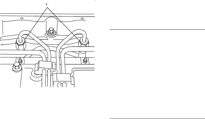
Fuel Injection Lines
|
Illustration 1 |
g01333480 |
|
Cylinder and valve location |
|
|
(A) Inlet valve |
|
|
(B) Exhaust valve |
|
|
Bore ………………………………….. |
105 mm (4.133 inch) |
|
Stroke ……………………………….. |
127 mm (5.000 inch) |
|
Displacement ……………………………….. |
4.4 L (269 in3) |
|
Cylinder arrangement ………………………………. |
In-line |
|
Type of combustion ………………………. |
Direct injection |
|
Compression ratio |
|
|
Naturally aspirated engines |
…………………. 19.3:1 |
|
Turbocharged engines ………………………… |
18.2:1 |
|
Number of cylinders ………………………………………… |
4 |
|
Valves per cylinder ………………………………………….. |
2 |
|
Valve lash |
|
|
Inlet valve ……………………. |
0.20 mm (0.008 inch) |
|
Exhaust valve ………………. |
0.45 mm (0.018 inch) |
|
Firing order …………………………………………. |
1, 3, 4, 2 |
When the crankshaft is viewed from the front of the engine, the crankshaft rotates in the following
direction: …………………………………………… Clockwise
|
Illustration 2 |
g01334606 |
|
Typical example |
(1) Tighten the union nuts for the fuel injector nozzles to the following torque. …………. 30 N·m (22 lb ft)
Tighten the union nuts for the fuel injection pump (not shown) to the following torque. ……. 30 N·m (22 lb ft)

|
KENR6245 |
5 |
|
Specifications Section |
i02663071
Fuel Injection Pump
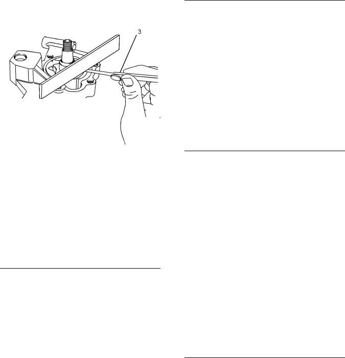
Note: Before the fuel injection pump is removed from the engine the fuel injection pump shaft must be locked. Position the engine to TC compression stroke of number one cylinder before tightening the locking screw. The locking screw will prevent the shaft from rotating. If the fuel injection pump was removed prior to correctly timing the engine and locking the shaft, the fuel injection pump will need to be timed by trained personnel.
|
Illustration 3 |
g01352237 |
|
Typical example |
Note: The solenoid on the fuel injection pump is a serviceable item. The fuel injection pump is a nonserviceable item.
(1)O-ring
(2)Locking screw
(3)Washer
Locking the shaft
Loosen locking screw (2) and move the washer
(3) to the locked position. Tighten the bolt to the following torque. …………………. 17 N·m (12 lb ft)
Unlocking the shaft
Loosen locking screw (2) and install the washer
(3) to the unlocked position. Tighten the bolt to the following torque. ………………. 12 N·m (9 lb ft)
|
Illustration 4 |
g01352239 |
|
|
Typical example of a support bracket |
||
|
(4) |
Tighten the mounting bolt to the following |
|
|
torque. ……………………………….. |
44 N·m (32 lb ft) |
|
|
(5) |
Tighten the mounting bolt and the nut to the |
|
|
following torque. ………………….. |
22 N·m (16 lb ft) |
Note: The support bracket must be installed after the coolant pump is installed. In order to stop the distortion of the timing case, finger tighten the bolt
(4) and then tighten the nut and bolt (5). Tighten the bolt (4).
Tighten the bolts that hold the fuel pump to the front housing to the following torque. …… 25 N·m (18 lb ft)

|
6 |
KENR6245 |
|
|
Specifications Section |
||
|
i02662510 |
i02661897 |
|
|
Fuel Injectors |
Fuel Transfer Pump |
|
|
Illustration 5 |
g00908211 |
|
Fuel injector clamp |
(1) Tighten the bolt in the clamp for the fuel injector to the following torque. …………. 35 N·m (26 lb ft)
The fuel injector should be tested at the pressure in table 1.
|
Leakage in 10 seconds …………………………… |
0 drops |
Table 1
Service setting for the Fuel Injector
Injection Pressure
29.4 + 0.8 MPa (4264 + 116 psi)
(1)Retaining bolts
(2)Clip
(3)Spacer
(4)Fuel transfer pump
Type …………………….. 12 or 24 volt electric motor
(5)Fuel filter element
(6)O ring
(7)Fuel filter bowl
Note: Tighten the fuel filter bowl by hand. Rotate the bowl 1/8 of a turn more by hand.
|
KENR6245 |
7 |
|
Specifications Section |
i02677369
Lifter Group
(1) Diameter of the lifter body .. 18.987 to 19.012 mm (0.7475 to 0.7485 inch)
Clearance of the lifter in the cylinder block
bore ……. 0.038 to 0.095 mm (0.0015 to 0.0037 inch)
i02655105
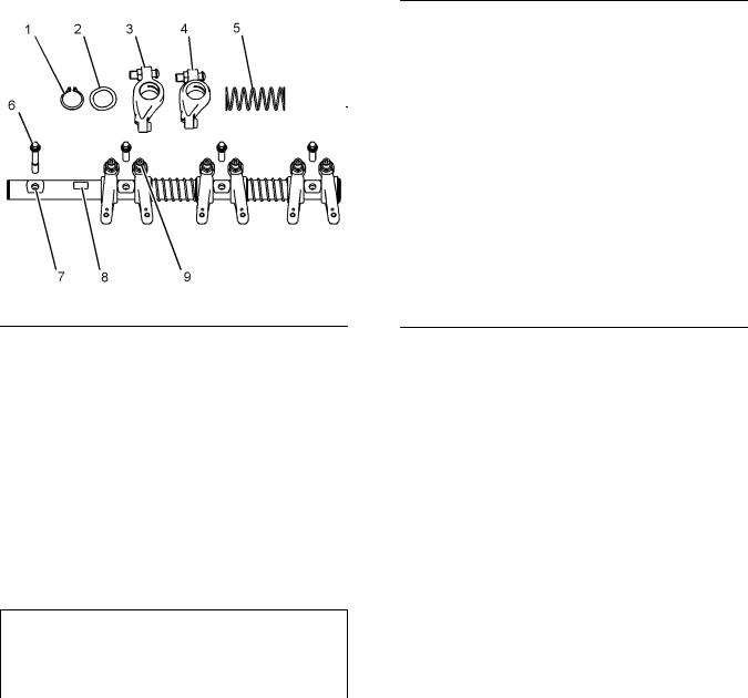
Rocker Shaft
Table 2
Required Tools
|
Part |
|||
|
Tool |
Number |
Part Description |
Qty |
|
A |
27610227 |
Spacing Tool |
4 |
|
Illustration 8 |
g01345401 |
|
The rocker shaft |
Note: In order to install the rocker shaft assembly, Tooling (A) is required.
(1)Snap ring
(2)Washer
(3)Rocker arm
(4)Rocker arm bore
Diameter of the rocker arm
|
bore ……………………………. |
25.013 to 25.051 mm |
|
(0.9848 to 0.9863 inch) |
|
|
Rocker arm |
Clearance between the rocker arm and the rocker
|
shaft |
……………………………….. 0.026 to 0.089 mm |
|
|
(0.0010 to 0.0035 inch) |
||
|
Maximum permissible clearance between the |
||
|
rocker arm and the rocker shaft |
………… 0.17 mm |
|
|
(0.007 inch) |
(5) Spring
Note: Install the longest screw at the front of the rocker shaft assembly.
(6)Tighten the screws evenly. Begin in the center and work toward the outside. Tighten the screws
|
to the following torque. …………. |
35 N·m (26 lb ft) |
|
(7) Rocker shaft |
|
|
Diameter of the rocker |
|
|
shaft ……………………………. |
24.962 to 24.987 mm |
|
(0.9828 to 0.9837 inch) |
|
8 |
KENR6245 |
|
Specifications Section |
(8)In order to install the rocker shaft assembly, ensure that the machined square is to the top of the rocker shaft.
(9)Locknut
Torque for the locknut …………… 27 N·m (20 lb ft)
i02551219
Valve Mechanism Cover
i02662486
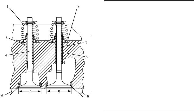
Cylinder Head Valves
Tighten the bolts for the valve mechanism cover in the sequence that is shown to the following
torque. …………………………………………. 9 N·m (7 lb ft)
|
Illustration 10 |
g01345407 |
|
Cross section of cylinder head |
(1)Valve spring
Naturally aspirated engines
|
The installed length of the valve |
||
|
springs …………………….. |
35.17 mm (1.3846 inch) |
|
|
The load for the installed valve springs ….. |
335 N |
|
|
(75 lb) |
Turbocharged engines
The installed length of the inlet valve springs
|
(high ratings) …………….. |
35.17 mm (1.3846 inch) |
|
The load for the installed inlet valve |
|
|
springs ……………………………………. |
335 N (75 lb) |
The installed length of the inlet valve springs (low
|
ratings) …………………….. |
36.17 mm (1.4240 inch) |
|
The load for the installed inlet valve |
|
|
springs ……………………………………. |
312 N (70 lb) |
The installed length of the exhaust valve springs
|
(all ratings) ……………….. |
36.17 mm (1.4240 inch) |
|
The load for the installed exhaust valve |
|
|
spring ……………………………………… |
312 N (70 lb) |
|
KENR6245 |
9 |
|
Specifications Section |
|
Turbocharged aftercooled engines |
||
|
The installed length of the valve |
||
|
springs …………………….. |
36.17 mm (1.4240 inch) |
|
|
The load for the installed valve springs ….. |
312 N |
|
|
(70 lb) |
(2)Valve spring recess
(3)The finished valve guides
|
Inside diameter of valve |
9.000 to 9.022 mm |
|
guide ………………………………. |
|
|
(0.3543 to 0.3552 inch) |
|
|
Outside diameter of the valve |
|
|
guide …………………………… |
13.034 to 13.047 mm |
|
(0.5131 to 0.5137 inch) |
|
|
Interference fit of valve guide in cylinder |
|
|
head ……………………………….. |
0.007 to 0.047 mm |
|
(0.0003 to 0.0019 inch) |
|
|
Length of Valve guide ………. |
51.00 to 51.50 mm |
|
(2.018 to 2.027 inch) |
|
|
Projection of the valve guide above the valve |
|
|
spring recess (2) ………………. |
12.35 to 12.65 mm |
|
(0.486 to 0.498 inch) |
Note: When new valve guides are installed, new valves and new valve seat inserts must be installed. The valve guides and the valve seat inserts are supplied as partially finished parts. The unfinished valve guides and unfinished valve seat inserts are installed in the cylinder head. The guides and inserts are then cut and reamed in one operation with special tooling. This procedure ensures the concentricity of the valve seat to the valve guide in order to create a seal that is tight. Refer to Disassembly and Assembly for removal and installation procedures.
(4) Exhaust valve
Diameter of the exhaust valve
|
stem |
……………………………….. 8.938 to 8.960 mm |
|
(0.3519 to 0.3528 inch) |
|
|
Clearance of valve in valve |
|
|
guide ….. |
0.040 to 0.062 mm (0.0016 to 0.0024 inch) |
|
Overall length of the exhaust |
|
|
valve …………………………….. |
128.184 to 128.634 mm |
|
(5.0466 to 5.0643 inch) |
The face of the exhaust valve is recessed below the cylinder head by the following amount.
|
Naturally aspirated engines |
………… 0.55 to 0.81 mm |
|
(0.0217 to 0.0319 inch) |
|
|
Service limit ………………………. |
1.06 mm (0.042 inch) |
|
Turbocharged engines ……………….. |
1.55 to 1.81 mm |
|
(0.0610 to 0.0713 inch) |
|
Service limit ……………………… |
2.06 mm (0.0811 inch) |
Turbocharged aftercooled engines .. 1.55 to 1.81 mm (0.0610 to 0.0713 inch)
Service limit ……………………… 2.06 mm (0.0811 inch)
(5) Inlet valve
Diameter of the inlet valve
|
stem ……………………………….. |
8.953 to 8.975 mm |
|
(0.3525 to 0.3533 inch) |
|
|
Clearance of valve in valve |
|
|
guide .. |
0.025 to 0.069 mm (0.001 to 0.0027 inch) |
|
Overall length of the inlet |
|
|
valve …………………………….. |
128.838 to 129.288 mm |
|
(5.0724 to 5.0901 inch) |
The face of the inlet valve is recessed below the cylinder head by the following amount.
|
Naturally aspirated engines |
………… 0.60 to 0.85 mm |
|
(0.0236 to 0.0335 inch) |
Turbocharged engines (high rating) .. 0.60 to 0.85 mm (0.0236 to 0.0335 inch)
Service limit ………………………. 1.09 mm (0.043 inch)
Turbocharged engines (low rating) .. 1.60 to 1.85 mm (0.0630 to 0.0728 inch)
Turbocharged aftercooled engines .. 1.60 to 1.85 mm (0.0630 to 0.0728 inch)
|
Service limit …………………….. |
2.09 mm (0.0823 inch) |
|
|
(6) |
Exhaust valve face angle from the horizontal axis |
|
|
Valve face angle …………………………. |
30 degrees |
|
|
Valve seat angle …………………………. |
30 degrees |
|
|
(7) |
Diameter of the exhaust |
|
|
valve head ………………………. |
41.51 to 41.75 mm |
|
|
(1.634 to 1.643 inch) |
||
|
(8) |
Diameter of the head of the inlet |
|
|
valve ………………………………. |
46.28 to 46.53 mm |
|
|
(1.8220 to 1.8319 inch) |
||
|
(9) |
Angle of the inlet valve face from the vertical axis |
|
|
Valve face angle …………………………. |
45 degrees |
|
|
Valve seat angle …………………………. |
45 degrees |
The valve lash is the following value when the engine is cold:
|
Inlet valves …………………… |
0.20 mm (0.008 inch) |
|
Exhaust valves …………….. |
0.45 mm (0.018 inch) |

|
10 |
KENR6245 |
|
Specifications Section |
|
Illustration 11 |
g00809016 |
|
Recess for the valve seat insert |
(10) Machine the recess in the head for valve seat inserts to the following dimensions.
Recess for Inlet Valve Seat for Naturally Aspirated Engines and high rated turbocharged engines
|
(A) ….. |
9.84 to 10.04 mm (0.3874 to 0.3953 inch) |
|
|
(B) ………………………………. |
47.820 to 47.845 mm |
|
|
(1.8827 to 1.8837 inch) |
||
|
(C) Maximum radius |
……… 0.38 mm (0.015 inch) |
Recess for Exhaust Valve Seat for Naturally Aspirated Engines and high rated turbocharged engines
|
(A) ….. |
9.84 to 10.04 mm (0.3874 to 0.3953 inch) |
|
|
(B) ………………………………. |
42.420 to 42.445 mm |
|
|
(1.6701 to 1.6711 inch) |
||
|
(C) Maximum radius |
……… 0.38 mm (0.015 inch) |
Recess for Inlet Valve Seat for low rated turbocharged engines and turbocharged aftercooled engines
(A) …. 10.84 to 11.04 mm (0.4268 to 0.4346 inch)
|
(B) ………………………………. |
47.820 to 47.845 mm |
|
(1.8827 to 1.8837 inch) |
|
|
(C) Maximum radius ……… |
0.38 mm (0.015 inch) |
Recess for Exhaust Valve Seat for turbocharged engines and turbocharged aftercooled engines
|
(A) …. |
10.84 to 11.04 mm (0.4268 to 0.4346 inch) |
|
|
(B) ………………………………. |
42.420 to 42.445 mm |
|
|
(1.6701 to 1.6711 inch) |
||
|
(C) Maximum radius |
……… 0.38 mm (0.015 inch) |
i02662502
Cylinder Head
Table 3
Required Tools
|
Part |
|||
|
Tool |
Number |
Part Description |
Qty |
|
A |
21825607 |
Angle gauge |
1 |
The maximum distortion of the cylinder head is given in table 4.
The cylinder head bolts are two different lengths. The following information provides the proper torque for the cylinder head bolts.
|
Illustration 12 |
g00987480 |
|
The tightening sequence |
Lubricate the threads and the underside of the head bolts with clean engine oil.
Tighten the bolts in the sequence that is shown in
|
Illustrations to the following torque. ……… |
50 N·m |
|
|
Tighten the bolts again to the following |
(37 lb ft) |
|
|
torque. ……………………………… |
100 N·m (74 lb ft) |
|
KENR6245 |
11 |
|
Specifications Section |
|
Illustration 13 |
g00905621 |
The head bolts require an additional torque turn procedure. The numbers (1, 3, 4) are three long cylinder head bolts. All the other bolts are short bolts. The tightening sequence is shown in the Illustrations .
Place the angle gauge on the top of each bolt head. Tighten the short bolts to the additional amount. ……………………………………. 225 degrees Place the angle gauge on the top of each bolt head. Tighten the long bolts for the additional
|
amount. ……………………………………. |
270 degrees |
|
|
Thickness of the cylinder head .. |
117.95 to 118.05 mm |
|
|
(4.643 to 4.647 inch) |
||
|
Minimum thickness of cylinder head |
…….. 117.20 mm |
|
|
(4.614 inch) |
Note: The maximum distortion of the cylinder head is given in table 4.
|
Illustration 14 |
g01006568 |
|
|
Table 4 |
||
|
Dimension |
Maximum Permissible |
|
|
Distortion |
||
|
Width (A) |
0.03 mm (0.0012 inch) |
|
|
Length (B) |
0.05 mm (0.0019 inch) |
|
|
Diagonal Line (C) |
0.05 mm (0.0019 inch) |
|
i02662519
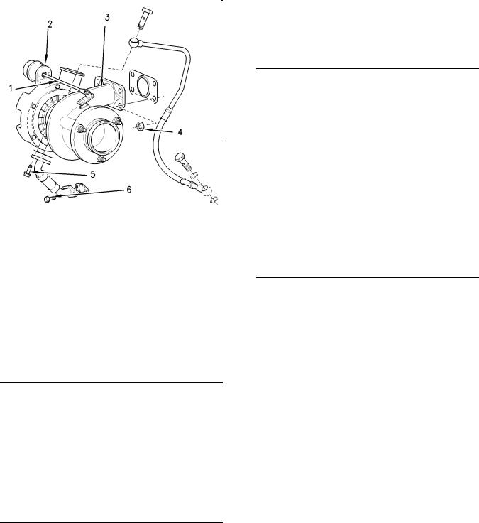
Turbocharger
|
Illustration 15 |
g00991357 |
|
Typical turbocharger |
(1)Actuator rod
(2)Actuator
(3)Turbocharger
|
(4) |
Tighten the nuts to the following torque. .. 44 N·m |
||
|
(32 lb ft) |
|||
|
(5) |
Tighten the bolt to the following torque. |
….. 9 N·m |
|
|
(80 lb in) |
|||
|
(6) |
Tighten the bolt to the following torque. … |
22 N·m |
|
|
(16 lb ft) |
|||
|
The maximum test pressure for the |
|||
|
wastegate ………………………………… |
205 kPa (30 psi) |
||
|
The movement for the rod actuator …………….. |
1 mm |
||
|
(0.0394 inch) |
|
12 |
KENR6245 |
|
Specifications Section |
Table 5
|
The part number for |
The pressure for the |
|
|
the turbocharger |
wastegate |
|
|
2674A835 |
138 |
± 3 kPa |
|
(20.0155 ± 0.4351 psi) |
||
|
2674A841 |
123 |
± 3 kPa |
|
(17.8399 ± 0.4351 psi) |
||
|
2674A843 |
138 |
± 3 kPa |
|
(20.0155 ± 0.4351 psi) |
||
|
2674A816 |
131 |
± 3 kPa |
|
(19.0002 ± 0.4351 psi) |
||
|
2674A817 |
100 |
± 3 kPa |
|
(14.5040 ± 0.4351 psi) |
||
|
2674A836 |
138 |
± 3 kPa |
|
(20.0155 ± 0.4351 psi) |
||
|
2674A818 |
123 |
± 3 kPa |
|
(17.8399 ± 0.4351 psi) |
||
|
2674A844 |
138 |
± 3 kPa |
|
(20.0155 ± 0.4351 psi) |
||
|
2674A819 |
131 |
± 3 kPa |
|
(19.0002 ± 0.4351 psi) |
||
|
2674A821 |
100 |
± 3 kPa |
|
(14.5040 ± 0.4351 psi) |
||
|
2674A837 |
138 |
± 3 kPa |
|
(20.0155 ± 0.4351 psi) |
||
|
2674A822 |
123 |
± 3 kPa |
|
(17.8399 ± 0.4351 psi) |
||
|
2674A838 |
138 |
± 3 kPa |
|
(20.0155 ± 0.4351 psi) |
||
|
2674A825 |
123 |
± 3 kPa |
|
(17.8399 ± 0.4351 psi) |
||
|
2674A845 |
138 |
± 3 kPa |
|
(20.0155 ± 0.4351 psi) |
||
|
2674A826 |
131 |
± 3 kPa |
|
(19.0002 ± 0.4351 psi) |
||
|
2674A827 |
100 |
± 3 kPa |
|
(14.5040 ± 0.4351 psi) |
||
|
2674A842 |
138 |
± 3 kPa |
|
(20.0155 ± 0.4351 psi) |
i02662527
Exhaust Manifold
|
Illustration 16 |
g01337856 |
|
Typical example |
Tighten the exhaust manifold bolts in the sequence that is shown in illustration 16 to the following
|
torque. ……………………………………… |
40 N·m (30 lb ft) |
|
i02662539 |
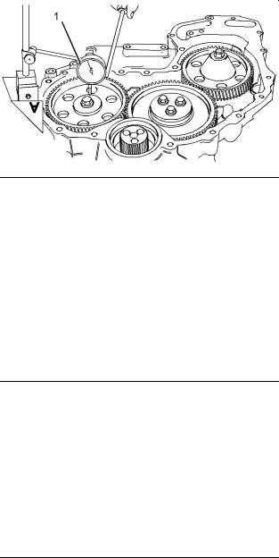
Camshaft
|
Illustration 17 |
g01277351 |
|
Checking the end play of the camshaft |
|
KENR6245 |
13 |
|
Specifications Section |
|
(1) End play of a new camshaft |
….. 0.10 to 0.55 mm |
|
(0.004 to 0.022 inch) |
|
|
Maximum permissible end play of a worn |
|
|
camshaft …………………………… |
0.60 mm (0.023 inch) |
|
Illustration 18 |
g01277354 |
|
Typical camshaft |
(2) Bolt
Tighten the bolt to the following torque. … 95 N·m (70 lb ft)
(3) Camshaft thrust washer
Thickness of the thrust washer .. 5.49 to 5.54 mm (0.216 to 0.218 inch)
Depth of the recess in the cylinder block for the
|
thrust washer |
………………………. 5.54 to 5.64 mm |
|
(0.218 to 0.222 inch) |
Tolerance of the thrust washer in cylinder block
|
front face |
……………………… −0.154 to −0.003 mm |
|
( − 0.0006 to −0.0001 inch) |
(4)The diameters of the camshaft journals are given in the following table.
Table 6
Diameters of Camshaft Journals
|
Camshaft Journals |
Standard Diameter |
|
|
1 |
50.711 to 50.737 mm |
|
|
(1.9965 to 1.9975 inch) |
||
|
2 |
50.457 to 50.483 mm |
|
|
(1.9865 to 1.9875 inch) |
||
|
3 |
49.949 to 49.975 mm |
|
|
(1.9665 to 1.9675 inch) |
||
Maximum wear on the camshaft journals … 0.05 mm (0.0021 inch)
|
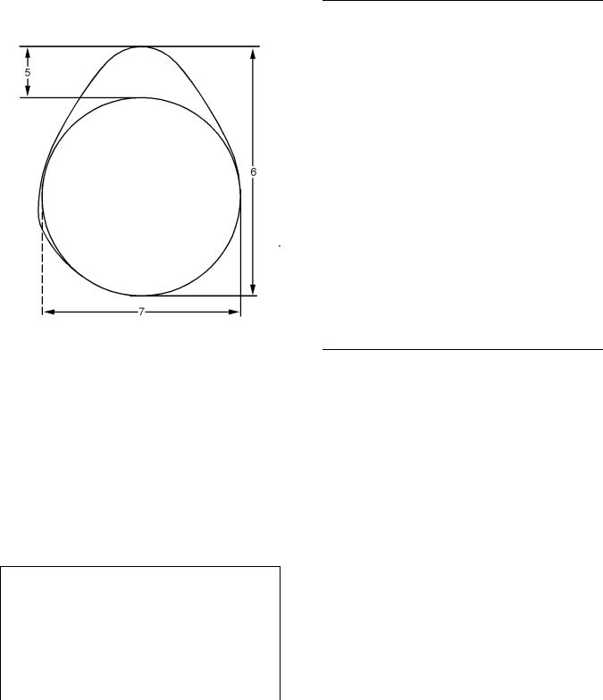
Illustration 19 |
g01345411 |
|
Typical example |
|
|
(5) Camshaft lobe lift |
|
|
Naturally aspirated |
|
|
Inlet lobe …………………………. |
7.201 to 7.301 mm |
|
(0.2835 to 0.2874 inch) |
|
|
Exhaust lobe ……………………. |
7.404 to 7.504 mm |
|
(0.2914 to 0.2954 inch) |
|
|
Turbocharged |
|
|
Inlet lobe …………………………. |
7.527 to 7.627 mm |
|
(0.2963 to 0.3003 inch) |
|
|
Exhaust lobe ……………………. |
7.363 to 7.463 mm |
|
(0.2899 to 0.2938 inch) |
|
|
Turbocharged aftercooled |
|
|
Inlet lobe …………………………. |
7.031 to 7.131 mm |
|
(0.2768 to 0.2807 inch) |
|
|
Exhaust lobe ……………………. |
7.363 to 7.463 mm |
|
(0.2899 to 0.2938 inch) |
(6)Camshaft lobe height
(7)Base circle
To determine the lobe lift, use the procedure that follows:
1.Mount the camshaft between centers.
2.By using a dial indicator in contact with the surface of the lobe, rotate the camshaft and record the maximum and minimum lift.
|
14 |
KENR6245 |
|
Specifications Section |
Note: There may be two lobes on the camshaft. Refer to illustration 19. The surface between the lobes may not return to the radius of the base circle. Using a micrometer to measure the diameter of the base circle may give a inaccurate result.
3.Subtract the smallest dimension from the largest dimension. The difference is the actual camshaft lobe lift.
Maximum permissible deviation between the actual lobe lift and the specified lobe lift of a new
|
camshaft …………………………… |
0.05 mm (0.002 inch) |
|
i02656416 |
Camshaft Bearings
i02663064
Engine Oil Filter
Illustration 20 Typical example
|
Illustration 21 |
g01338237 |
|
|
Typical example |
||
|
(1) |
Setscrew |
|
|
Tighten the setscrews to the following |
||
|
torque. ……………………………….. |
22 N·m (16 lb ft) |
|
|
(2) |
Engine oil filter |
|
|
Tighten the engine oil filter to the following |
||
|
torque. ……………………………… |
12 N·m (106 lb in) |
g01334592
(1) The diameter of the installed camshaft
|
bearing |
………………………… 50.787 to 50.848 mm |
|
(1.9995 to 2.0019 inch) |
|
KENR6245 |
15 |
|
Specifications Section |
|
Illustration 22 |
g01338238 |
|
|
Typical example |
||
|
(3) |
Setscrew |
|
|
Tighten the setscrews to the following |
||
|
torque. ……………………………….. |
22 N·m (16 lb ft) |
|
|
(4) |
Engine oil filter |
|
|
Tighten the engine oil filter to the following |
||
|
torque. ……………………………… |
12 N·m (106 lb in) |
|
|
(5) |
Plug |
|
|
Tighten the plug to the following torque. .. 12 N·m |
||
|
(106 lb in) |
i02657143
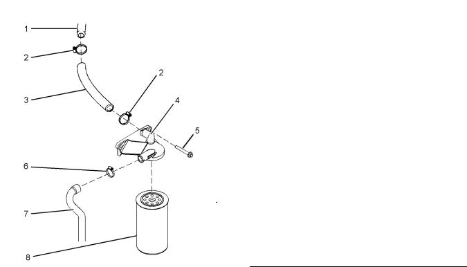
Engine Oil Cooler
|
Illustration 23 |
g00952614 |
|
|
Typical example |
||
|
(1) |
Joint |
|
|
(2) |
Oil cooler |
|
|
(3) |
Housing |
|
|
(4) |
Setscrew |
|
|
(5) |
Seal |
|
|
(6) |
Setscrew |
|
|
(7) |
Setscrew |
|
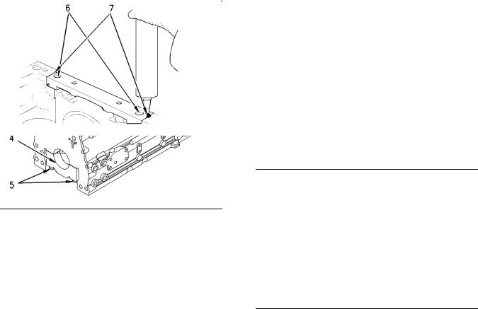
|
Illustration 24 |
g01334858 |
Setscrews
Tighten the setscrews (7) to the following torque. ……………………………….. 22 N·m (16 lb ft)
Setscrews
Tighten the setscrews (4) and (6) in the sequence that is in illustration 24 to the following torque. ……………………………….. 22 N·m (16 lb ft)
|
16 |
KENR6245 |
|
Specifications Section |
i02656269
Engine Oil Pump
Engines with Balancer Group
|
Type ……………………….. |
Gear-driven differential rotor |
|
Number of lobes |
|
|
Inner rotor ………………………………………………… |
6 |
|
Outer rotor ……………………………………………….. |
7 |
|
Illustration 25 |
g01334408 |
|
The oil pump for the balancer |
(1) Clearance of the outer rotor to the
body .. 0.130 to 0.24 mm (0.0050 to 0.0094 inch)
|
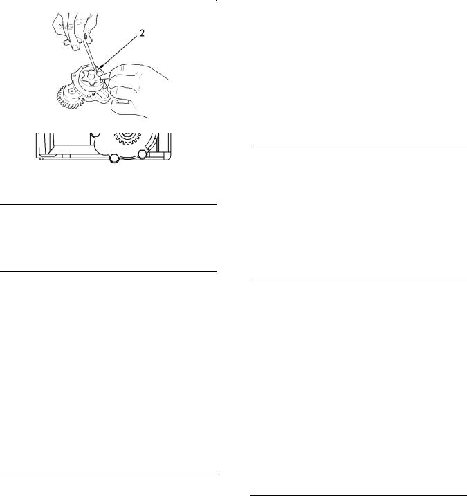
Illustration 26 |
g01334410 |
|
Inner rotor |
|
|
(2) Clearance of inner rotor to outer |
|
|
rotor ……………………………….. |
0.050 to 0.200 mm |
|
(0.0020 to 0.0079 inch) |
|
|
Illustration 27 |
g01334412 |
|
The end play for the rotor |
|
|
(3) End play of rotor assembly |
|
|
Inner rotor ……………………………. |
0.04 to 0.11 mm |
|
(0.0016 to 0.0043 inch) |
|
|
Outer rotor …………………………… |
0.04 to 0.11 mm |
|
(0.0016 to 0.0043 inch) |
|
KENR6245 |
17 |
|
Specifications Section |
|
Illustration 28 |
g01334415 |
|
The end cover |
(4) Torque for cover bolts for oil pump ………. 26 N·m (19 lb ft)
|
Illustration 29 |
g01334416 |
|
Idler gear and pump gear |
Note: Replace the idler gear bolt (5) and the nut for the oil pump gear (6).
(5) Tighten the idler gear bolt to the following torque. ……………………………….. 26 N·m (19 lb ft)
Note: Set the engine to the TC position. Refer to Systems Operation, Testing and Adjusting Manual, “Finding Top Center Position for No. 1 Piston”. Install the balancer. Refer to Disassembly and Assembly, “Balancer — Install”. Install the gear for the oil pump and tighten the nut (6).
|
(6) Tighten the nut to the following torque. …. 95 N·m |
||
|
(70 lb ft) |
||
|
Tighten the bolts that hold the balancer to the cylinder |
||
|
block to the following torque. ………. |
54 N·m (40 lb ft) |
|
|
Engines without Balancer Group |
||
|
Type ……………………….. |
Gear-driven differential rotor |
|
|
Number of lobes |
||
|
Inner rotor ………………………………………………… |
5 |
|
|
Outer rotor ……………………………………………….. |
6 |
|
Illustration 30 |
g00938064 |
|
The oil pump |
|
|
(1) Clearance of the outer rotor to the |
|
|
body ……………………………….. |
0.152 to 0.330 mm |
|
(0.0059 to 0.0129 inch) |
|
|
Illustration 31 |
g00938061 |
|
Checking the clearance |
|
|
(2) Clearance of inner rotor to outer |
|
|
rotor ……………………………….. |
0.040 to 0.127 mm |
|
(0.0015 to 0.0050 inch) |
|
18 |
KENR6245 |
|
Specifications Section |
|
Illustration 32 |
g00938799 |
|
Checking the end play |
|
|
(3) End play of rotor assembly |
|
|
Inner rotor ……………………….. |
0.038 to 0.089 mm |
|
(0.0014 to 0.0035 inch) |
|
|
Outer rotor ………………………. |
0.025 to 0.076 mm |
|
(0.0010 to 0.0029 inch) |
Tighten the bolts that hold the front cover of the oil
|
pump assembly to the following torque. |
…….. 10 N·m |
|
(89 lb in) |
|
|
i02731019 |
Engine Oil Pressure
The minimum oil pressure at the maximum engine speed and at normal operating temperature is the following value. …………………………. 280 kPa (41 psi)
i02505676
Engine Oil Bypass Valve
Installed in the Oil Pump
|
Illustration 33 |
g00919893 |
|
Typical engine oil pump |
|
|
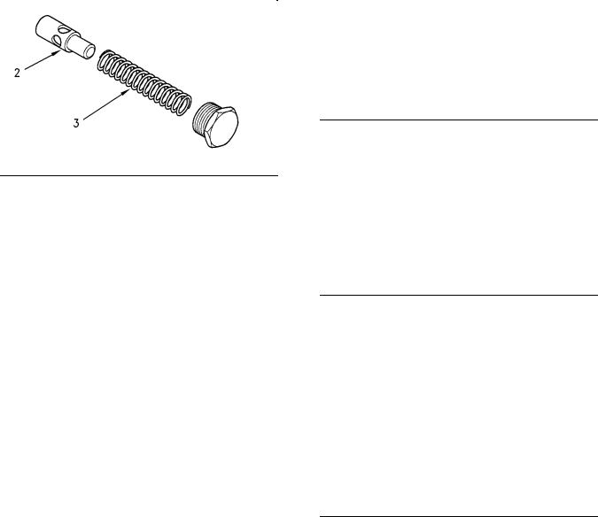
Illustration 34 |
g00921377 |
|
Relief valve and spring |
(1)Tighten the plug for the relief valve to the following torque. ………………….. 35 N·m (26 lb ft)
(2)Plunger
Diameter of the plunger ….. 19.186 to 19.211 mm
(0.7554 to 0.7563 inch)
Clearance of plunger in bore .. 0.039 to 0.114 mm (0.0015 to 0.0045 inch)
(3)Spring
Length of the spring …… 80.94 mm (3.1866 inch)
![]()
|
KENR6245 |
19 |
|
Specifications Section |
Installed in the Balancer
|
Illustration 35 |
g00919890 |
|
Plug |
|
|
Illustration 36 |
g00921379 |
||
|
The relief valve for the balancer |
|||
|
(1) |
Tighten the plug for the relief valve to the |
||
|
following torque. ………………….. |
35 N·m (26 lb ft) |
||
|
(2) |
Plunger |
||
|
Diameter of the plunger …….. |
14.46 to 14.48 mm |
||
|
(0.5692 to 0.5700 inch) |
|||
|
Clearance of the plunger in the |
|||
|
bore …. |
0.04 to 0.08 mm (0.0015 to 0.0031 inch) |
||
|
(3) |
Spring |
||
|
Length of the spring ……….. |
67 mm (2.6378 inch) |
i02662550
Engine Oil Pan
Table 7
Required Tools
|
Tool |
Part Number |
Part Description |
Qty |
|
|
A |
21826038 |
POWERPART |
1 |
|
|
Retainer |
||||
Front sealant
|
Illustration 37 |
g01254690 |
|
Applying sealant |
If the gasket that is between the front housing and the cylinder block is not renewed, apply Tooling (A) to the cylinder block and to the front housing. If a new gasket is installed, Tooling (A) is not required.
Note: Apply a sealant bead of 3.5 mm (0.1378 inch) that is shown in illustration 37.
Rear sealant
Note: Install the rear oil seal before sealant is applied to the bridge.
|
20 |
KENR6245 |
|
|
Specifications Section |
||
|
Tighten the remaining bolts to the following |
||
|
. ………………………………………torque |
22 N·m (16 lb ft) |
|
|
(2) Drain plug |
||
|
Tighten the drain plug for the engine oil pan to |
||
|
the following torque. …………….. |
34 N·m (25 lb ft) |
|
|
i02662638 |
Crankcase Breather
|
Table 8 |
|||||||
|
Required Tools |
|||||||
|
Part |
|||||||
|
Tool |
Number |
Part Description |
Qty |
||||
|
POWERPART red rubber |
|||||||
|
Illustration 38 |
g01254887 |
A |
21820221 |
1 |
|||
|
grease |
|||||||
|
Applying sealant |
|||||||
Apply Tooling (A) to the bridge. The sealant must not protrude more than 5 mm (0.1969 inch) above the bridge.
|
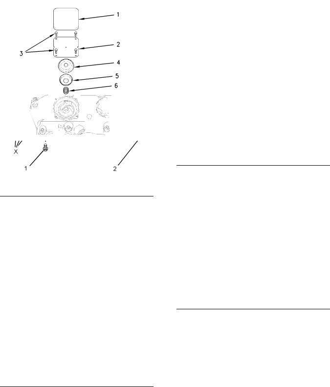
Illustration 39 |
g01255016 |
|
Typical example |
(1) Tighten the four front bolts in position (X) to the following torque. ………………….. 22 N·m (16 lb ft)
|
Illustration 40 |
g00926199 |
|
Breather valve |
(1)Cover
(2)Cover plate
(3)Screws
Tighten the screws for the cover plate with a composite valve mechanism cover to the
following torque. ………………. 1.3 N·m (11.5 lb in)
(4)Diaphragm
(5)Cap
|
KENR6245 |
21 |
|
|
Specifications Section |
||
|
(6) Spring |
Breather Canister |
|
|
Illustration 41 |
g00926200 |
|
Typical example |
(7) O-ring
Note: Apply Tooling (A) to the O-ring before installing the breather pipe in the valve mechanism cover.
(8)Tighten the bolts that secure the breather pipe to the cylinder head to the following torque. .. 9 N·m
(80 lb in)
|
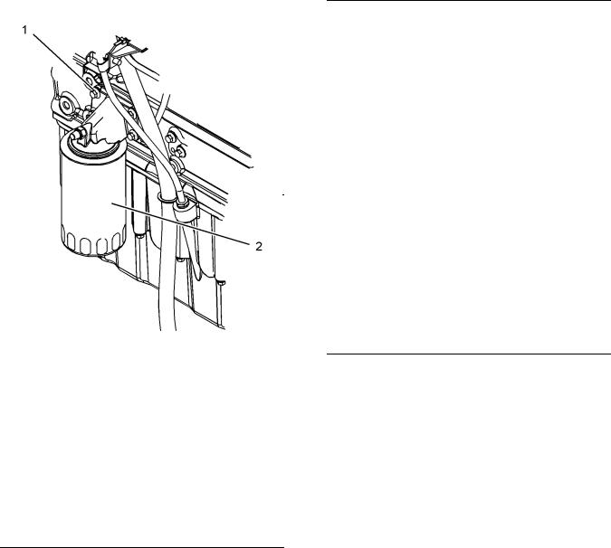
Illustration 42 |
g01277902 |
|
|
Typical example |
||
|
(1) |
Connection |
|
|
(2) |
Clamp |
|
|
(3) |
Hose |
|
|
(4) |
Filter base |
|
|
(5) |
Bolts |
|
|
(6) |
Clamp |
|
|
(7) |
Hose |
|
|
(8) |
Canister |
(2) Tighten the clamps to the following
torque. …………………………………. 3 N·m (26 lb in)
(5) Tighten the bolts to the following torque. .. 22 N·m (16 lb ft)
(6) Tighten the clamp to the following torque. .. 3 N·m (26 lb in)
(8) Tighten the canister to the following
torque. ……………………………… 12 N·m (106 lb in)
|
22 |
KENR6245 |
|
Specifications Section |
i02504533
Water Temperature Regulator and Housing
Table 9
Required Tools
|
Tool |
Part Number |
Part Description |
Qty |
|
|
A |
21820221 |
POWERPART Red |
1 |
|
|
Rubber Grease |
||||
|
Illustration 43 |
g01253716 |
|
Typical example |
Note: Apply Tooling (A) to the O-ring (4) in order to install the water temperature regulator housing (2).
(1) Tighten the bolts that fasten the housing to the following torque. ………………….. 44 N·m (32 lb ft)
(2)Water temperature regulator housing
(3)Water temperature regulator
|
Opening temperature …………………… |
82° to 87°C |
|
|
(179.6000° to 156.6000°F) |
||
|
Full opening temperature …. |
95 °C (203.0000 °F) |
|
|
Minimum stroke at full temperature |
……….. 9 mm |
|
|
(0.3543 inch) |
i02363605
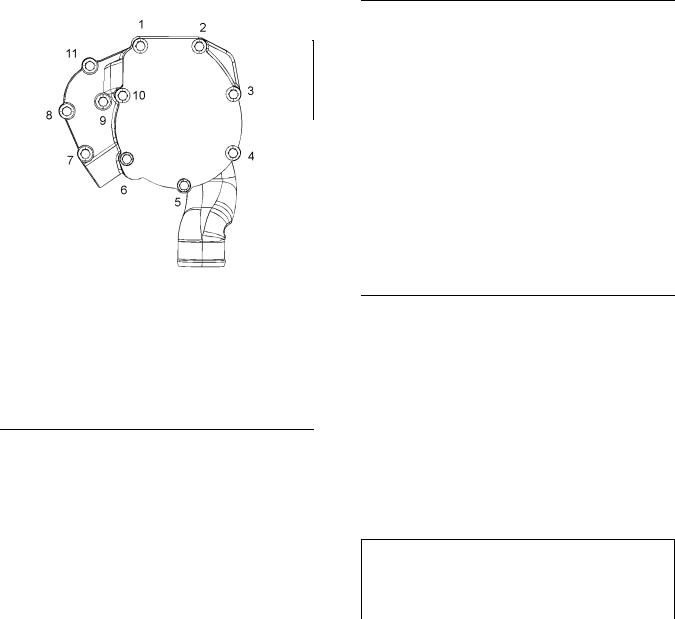
Water Pump
|
Illustration 44 |
g01183807 |
|
Tightening sequence |
Tighten the setscrews in the numerical sequence that is shown in illustration 44 to the following
|
torque. ……………………………………… |
22 N·m (16 lb ft) |
|
i02663067 |
Cylinder Block
Table 10
Required Tools
|
Tool |
Part Number |
Part Description |
Qty |
|
|
A |
21826038 |
POWERPART |
1 |
|
|
Retainer |
||||
|
KENR6245 |
23 |
|
Specifications Section |
|
Illustration 45 |
g00924764 |
|
Typical example |
|
|
(1) Cylinder block |
|
|
(2) Cylinder bore ……………. |
105.000 to 105.025 mm |
|
(4.1338 to 4.1348 inch) |
|
|
The first oversize bore |
|
|
diameter ……………………………. |
105.5 to 105.525 mm |
|
(4.1535 to 4.1545 inch) |
|
|
The second oversize bore |
|
|
diameter ………………………… |
106.000 to 106.025 mm |
|
(4.1732 to 4.1742 inch) |
The maximum permissible wear for the cylinder bore
…………………………… 0 to 0.15 mm (0 to 0.0059 inch)
(3)Camshaft bearings
Diameter of the bore in the cylinder
block for the number 1 camshaft
|
bearing |
………………………… 55.563 to 55.593 mm |
|
(2.1875 to 2.1887 inch) |
Diameter of the bore in the cylinder block for the number 2 camshaft
|
journal |
…………………………. 50.546 to 50.597 mm |
|
(1.9900 to 1.9920 inch) |
|
Diameter of the bore in the cylinder |
||
|
block for the number 3 camshaft |
||
|
journal …………………………. |
50.038 to 50.089 mm |
|
|
(1.9700 to 1.9720 inch) |
||
|
(4) |
Main bearings |
|
|
Bore in the cylinder block for the main |
||
|
bearings ………………………. |
80.416 to 80.442 mm |
|
|
(3.1660 to 3.1670 inch) |
||
|
(5) |
Main bearing cap bolts |
Use the following procedure in order to install the main bearing cap bolts:
1.Apply clean engine oil to the threads of the main bearing cap bolts.
2.Put the main bearing caps in the correct position that is indicated by a number on the top of the main bearing cap. Install the main bearing caps with the locating tabs in correct alignment with the recess in the cylinder block.
3.Evenly tighten the main bearing cap bolts. Torque for the main bearing cap bolts. …. 245 N·m
(180 lb ft)
|
Illustration 46 |
g00938203 |
Use the following procedure in order to install the allen head bolts for the bridge.
Note: Install the rear seal before sealant is applied.
1.Use a straight edge in order to ensure that the bridge is aligned with the rear face of the cylinder block.
2.Tighten the allen head bolts (6) for the bridge. Torque for the allen head bolts … 16 N·m (12 lb ft)
3.When the bridge is installed on the cylinder block, apply Tooling (A) into groove (7) at each end of the bridge. Apply the sealant into the groove until the sealant is forced through the bottom end of the groove in the bridge.
Note: The oil pan must be installed within 10 minutes of applying the sealant.
Total height of the cylinder block between the top and
|
the bottom faces. |
……………. 441.173 to 441.274 mm |
|
(17.3689 to 17.3729 inch) |
|
24 |
KENR6245 |
|
Specifications Section |
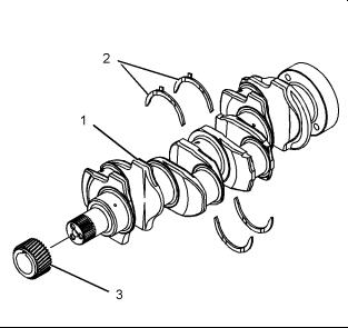
Crankshaft
i02663072 Note: All new turbocharged engines and turbocharged aftercooled engines have crankshafts that are nitrocarburised. The crankshaft can also be nitrided for 20 hours, if the nitrocarburised process is not available. After a crankshaft has been machined, the crankshaft must be rehardened. Inspect the crankshaft for cracks before machining and after machining. Naturally aspirated engines have induction hardened crankshafts.
|
Illustration 47 |
g01338264 |
|
Typical example |
(1) Crankshaft
The maximum end play of the crankshaft … 0.51 mm (0.0201 inch)
|
(2) |
Thrust washers |
|
|
Standard thickness ………………. |
2.26 to 2.31 mm |
|
|
(0.089 to 0.091 inch) |
||
|
Oversize thickness ………………. |
2.45 to 2.50 mm |
|
|
(0.097 to 0.098 inch) |
||
|
(3) |
The crankshaft gear |
|
|
Maximum permissible temperature of the gear for |
||
|
installation on the crankshaft ……….. |
180 °C (356 °F) |
Note: The timing mark is toward the outside of the crankshaft when the gear is installed on the crankshaft.

|
KENR6245 |
25 |
|
Specifications Section |
|
|
Illustration 48 |
g01338265 |
Note: Refer to illustration 48 in order to use table 11.
Table 11
The undersize diameter of the Crankshaft Journals
|
NUMBER |
0.25 mm (0.010 inch) |
0.51 mm (0.020 inch) |
0.76 mm (0.030 inch) |
|
|
1 |
75.905 to 75.926 mm |
75.651 to 75.672 mm |
75.397 to 75.418 mm |
|
|
(2.9884 to 2.9892 inch) |
(2.9784 to 2.9792 inch) |
(2.9684 to 2.9692 inch) |
||
|
2 |
63.216 to 63.236 mm |
62.962 to 62.982 mm |
62.708 to 62.728 mm |
|
|
(2.4888 to 2.4896 inch) |
(2.4788 to 2.4796 inch) |
(2.4688 to 2.4696 inch) |
||
|
3 |
39.47 mm (1.5539 inch) |
N/A |
N/A |
|
|
maximum |
||||
|
4 |
37.44 mm (1.4740 inch) |
N/A |
N/A |
|
|
maximum |
||||
|
5 |
44.68 mm (1.7591 inch) |
N/A |
N/A |
|
|
maximum |
||||
|
6 |
40.55 mm (1.5965 inch) |
N/A |
N/A |
|
|
maximum |
||||
|
7 |
Do not machine this diameter. |
N/A |
N/A |
|
|
8 |
3.68 mm (0.1449 inch) to |
N/A |
N/A |
|
|
3.96 mm (0.1559 inch) |
||||
|
9 |
4.36 to 4.60 mm |
N/A |
N/A |
|
|
(0.1717 to 0.1811 inch) |
||||
Refer to table 12 for the maximum run out of the crankshaft journals.
|
26 |
KENR6245 |
|
Specifications Section |
Table 12
|
Journal |
Excessive run out |
|
(1) |
Mounting |
|
(2) |
0.08 mm (0.0031 inch) |
|
(3) |
0.15 mm (0.0059 inch) |
|
(4) |
0.08 mm (0.0031 inch) |
|
(5) |
Mounting |
Refer to Specifications, “Connecting Rod Bearing Journal” for more information on the connecting rod bearing journals and connecting rod bearings.
Refer to Specifications, “Main Bearing Journal” for information on the main bearing journals and for information on the main bearings.
i02658811
Crankshaft Seals
|
Illustration 49 |
g01335894 |
|
Typical example |
(1)Crankshaft
(2)Crankshaft seal
(3)Plastic sleeve
(4)Alignment tool
|
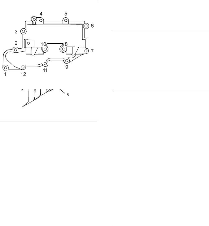
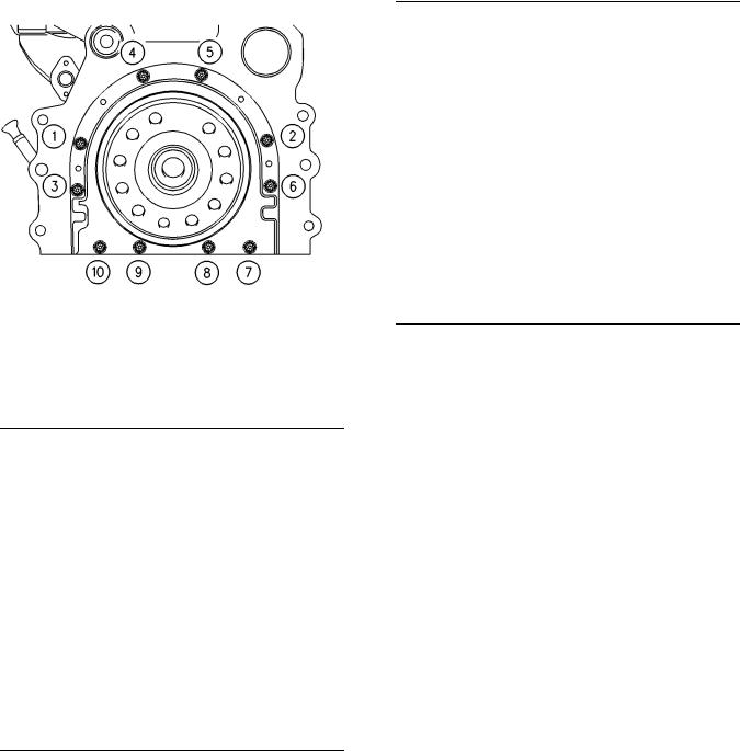
Illustration 50 |
g00915076 |
(5)Tighten bolts 1, 2, 3, 4, 5, 6, 7, and 10 in the sequence that is shown in Illustration 50 to the
|
following torque. ………………….. |
22 N·m (16 lb ft) |
|
Remove the alignment tool. |
Tighten bolts 8 and 9 in the sequence that is shown
|
in Illustration 50 to the following torque. |
…….. 22 N·m |
|
(16 lb ft) |
|
|
i02504771 |
Connecting Rod Bearing
Journal
Refer to Specifications, “Crankshaft” for information on the undersize crankshaft journals.
The original size of the connecting rod bearing journal … 63.47 to 63.49 mm (2.4988 to 2.4996 inch)
Maximum permissible wear of a bearing journal on a
|
new connecting rod ………….. |
0.04 mm (0.0016 inch) |
|
|
Width of the connecting rod bearing |
||
|
journals |
…………………………….. |
40.348 to 40.424 mm |
|
(1.5885 to 1.5915 inch) |
||
|
Radius of the fillet of the connecting rod bearing |
||
|
journals ……… |
3.68 to 3.96 mm (0.145 to 0.156 inch) |
|
|
Surface finish of connecting rod bearing |
||
|
journals ……………………………………… |
Ra 0.4 microns |
|
KENR6245 |
27 |
|
Specifications Section |
|
Surface finish of radii …………………… |
Ra 1.3 microns |
i02656267
Main Bearing Journal
Refer to Specifications, “Crankshaft” for information on the undersize main bearing journals, and information on the width of main bearing journals.
The original size of the main bearing
|
journal ………………………………. |
76.159 to 76.180 mm |
|
(2.9984 to 2.9992 inch) |
|
|
Maximum permissible wear of the main bearing |
|
|
journals …………………………. |
0.040 mm (0.0016 inch) |
|
Radius of the fillet of the main bearing |
|
|
journals ….. |
3.68 to 3.69 mm (0.1448 to 0.1452 inch) |
|
Surface finish of bearing journals, crank pins and |
|
|
radii …………………………….. |
0.4 microns (16 µ inches) |
The shell for the main bearings
The shells for the main bearings are available for remachined journals which have the following undersize dimensions.
|
Undersize bearing shell …. |
0.25 mm (0.010 inch) |
|
Undersize bearing shell …. |
0.51 mm (0.020 inch) |
|
Undersize bearing shell …. |
0.75 mm (0.030 inch) |
|
Thickness at center of the shells |
.. 2.083 to 2.089 mm |
|
(0.0820 to 0.0823 inch) |
|
|
Width of the main bearing shells |
.. 31.62 to 31.88 mm |
|
(1.244 to 1.255 inch) |
Clearance between the bearing shell and the main
|
bearing journals |
……………………… 0.057 to 0.117 mm |
|
(0.0022 to 0.0046 inch) |
i02662161
Connecting Rod
|
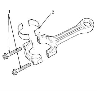
Illustration 51 |
g00907738 |
The mating surfaces of the connecting rod are produced by hydraulically fracturing the forged connecting rod.
(1)Tighten the torx screws for the connecting rod to the following torque. …………….. 18 N·m (13 lb ft)
Tighten the torx screws for the connecting rod again to the following torque. ……………….. 70 N·m (52 lb ft)
Tighten the torx screws for the connecting rod for an additional 120 degrees. The torx screws for the connecting rod (1) must be replaced after this procedure.
Note: Always tighten the connecting rod cap to the connecting rod, when the assembly is out of the engine. Tighten the assembly to the following torque 20 N·m (14 lb ft).
(2) The bearing shell for the connecting rod
|
28 |
KENR6245 |
|
|
Specifications Section |
||
|
Illustration 52 |
g00995584 |
|
Alignment of the bearing shell |
Note: The bearing shell for the connecting rod must be aligned equally from both ends of the connecting rod. Refer to (A) in figure 52. Refer to Disassembly and Assembly for information on the alignment tool.
Table 13
|
Bearing Width for the |
31.62 |
to 31.88 mm |
|
|
Connecting Rod |
(1.245 to 1.255 inch) |
||
|
Bearing Width for the |
31.62 |
to 31.88 mm |
|
|
Connecting Rod Cap |
(1.2449 to 1.2551 inch) |
||
|
Thickness of Connecting |
1.835 |
to 1.842 mm |
|
|
Rod Bearing at the |
|||
|
(0.0723 to 0.0725 inch) |
|||
|
Center |
|||
|
Thickness of Connecting |
1.835 |
to 1.842 mm |
|
|
Rod Bearing for the Cap |
|||
|
(0.0722 to 0.0725 inch) |
|||
|
at the Center |
|||
|
Bearing Clearance |
0.034 |
to 0.081 mm |
|
|
(0.0013 to 0.0032 inch) |
|||
Table 14
Undersized Connecting Rod Bearing
0.25 mm (0.010 inch)
0.51 mm (0.020 inch)
0.76 mm (0.030 inch)
|
Illustration 53 |
g00907744 |
|
|
(3) |
Inside diameter of the small |
|
|
bush ……………………………. |
39.723 to 39.738 mm |
|
|
(1.5639 to 1.5645 inch) |
||
|
(4) |
Distance between the parent |
|
|
bores …………………………… |
219.05 to 219.10 mm |
|
|
(8.624 to 8.626 inch) |
||
|
(5) |
Diameter for the parent bore for the connecting |
|
|
rod bearing ……………………… |
67.21 to 67.22 mm |
|
|
(2.6460 to 2.6465 inch) |
||
|
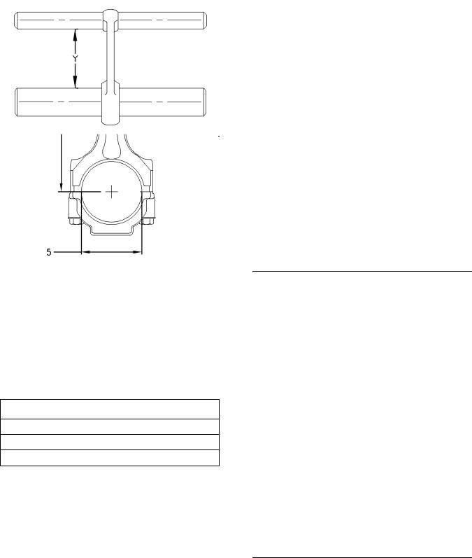
Illustration 54 |
g00915056 |
![]()
|
KENR6245 |
29 |
|
Specifications Section |
Connecting rods are color coded. The color code is a reference for the length (Y) of the connecting rod. Refer to table 15 for the different lengths of connecting rods.
Table 15
Length Grades for Connecting Rods
|
Grade Letter |
Color Code |
Length (Y) |
|
|
F |
Red |
165.728 to 165.761 mm |
|
|
(6.5247 to 6.5260 inch) |
|||
|
G |
Orange |
165.682 to 165.715 mm |
|
|
(6.5229 to 6.5242 inch) |
|||
|
H |
White |
165.637 to 165.670 mm |
|
|
(6.5211 to 6.5224 inch) |
|||
|
J |
Green |
165.591 to 165.624 mm |
|
|
(6.5193 to 6.5206 inch) |
|||
|
K |
Purple |
165.545 to 165.578 mm |
|
|
(6.5175 to 6.5188 inch) |
|||
|
L |
Blue |
165.499 to 165.532 mm |
|
|
(6.5157 to 6.4961 inch) |
|||
|
i02662142 |
Piston and Rings
|
Illustration 55 |
g01363510 |
|
Typical example |
(1)Top compression ring
Naturally Aspirated
The shape of the top compression
ring …………………. Rectangular with a barrel face
Width of the top compression
ring …… 2.47 to 2.49 mm (0.0972 to 0.0980 inch)
Clearance between the top compression ring and the piston groove …………………. 0.09 to 0.13 mm
(0.0035 to 0.0051 inch)
|
Ring gap …………………………….. |
0.30 to 0.55 mm |
|
|
(0.0118 to 0.0217 inch) |
||
|
Turbocharged |
||
|
The shape of the top compression |
||
|
ring ……………………… |
Keystone with a barrel face |
|
|
Width of the top compression ring ………. |
tapered |
|
|
Ring gap …………………………….. |
0.30 to 0.45 mm |
|
|
(0.0118 to 0.0177 inch) |
Note: When you install a new top compression ring, make sure that the word “TOP” is facing the top of the piston. New top piston rings for naturally aspirated engines have a red identification mark which must be on the left of the ring end gap when the top piston ring is installed on an upright piston. New top piston rings for turbocharged engines have a yellow identification mark which must be on the left of the ring end gap when the top piston ring is installed on an upright piston.
(2) Intermediate compression ring
The shape of the intermediate compression
|
ring ……………………………. |
Internal chamfer in the |
|
|
bottom edge with a tapered face |
||
|
Width of intermediate compression ring for |
||
|
naturally aspirated engines |
……. 2.47 to 2.49 mm |
|
|
(0.097 to 0.098 inch) |
||
|
Width of intermediate compression ring for |
||
|
turbocharged engines ……….. |
2.470 to 2.495 mm |
|
|
(0.0972 to 0.0982 inch) |
Clearance between the intermediate compression ring and the piston groove for naturally aspirated engines … 0.05 to 0.09 mm (0.002 to 0.003 inch)
Clearance between the intermediate compression ring and the piston groove for turbocharged
|
engines |
……………………………. 0.065 to 0.110 mm |
|
(0.0026 to 0.0043 inch) |
|
|
Ring gap for naturally aspirated |
|
|
engines |
………………………………. 0.70 to 0.95 mm |
|
(0.0275 to 0.0374 inch) |
|
|
Ring gap for turbocharged |
|
|
engines ………………………………. |
0.65 to 0.85 mm |
|
(0.0256 to 0.0335 inch) |
Note: When you install a new intermediate compression ring, make sure that the word “TOP” is facing the top of the piston. New intermediate rings for naturally aspirated engines have a green identification mark which must be on the left of the ring end gap when the top piston ring is installed on an upright piston. New intermediate rings for
turbocharged engines have a blue identification mark which must be on the left of the ring end gap when the top piston ring is installed on an upright piston.

|
30 |
KENR6245 |
|||
|
Specifications Section |
||||
|
(3) Oil control ring |
Piston pin |
|||
|
Shape of |
oil control |
Diameter of a new piston |
||
|
ring ………… |
a two-piece coil that is spring loaded |
pin ………………………………. |
39.694 to 39.700 mm |
|
|
Width of oil control ring for naturally aspirated |
(1.5628 to 1.5630 inch) |
|||
|
Diameter of the bore for the piston |
||||
|
engines ………………………………. |
3.47 to 3.49 mm |
|||
|
(0.1366 to 0.1374 inch) |
pin ………………………………. |
39.703 to 39.709 mm |
||
|
Width of oil control ring for turbocharged |
(1.5631 to 1.5633 inch) |
|||
|
engines ………………………………. |
2.97 to 2.99 mm |
|||
|
(0.1169 to 0.1177 inch) |
i02665602 |
|||
Clearance between the oil control ring and the groove in the piston for naturally aspirated
|
engines ………………………………. |
0.03 to 0.07 mm |
|
(0.0011 to 0.0027 inch) |
|
|
Ring gap …………………………….. |
0.30 to 0.55 mm |
|
(0.0118 to 0.0216 inch) |
Note: A pin is used in order to hold both ends of the spring of the oil control ring in position. The ends of the spring of the oil control ring must be installed opposite the end gap of the oil control ring.
Note: Ensure that the ring end gaps of the piston rings are spaced 120 degrees from each other.
Piston
Note: An arrow which is marked on the piston crown must be toward the front of the engine.
The combustion bowl re-entrant angle for the
|
turbocharged engine …………………………. |
72 degrees |
|
|
The combustion bowl re-entrant angle for the |
||
|
naturally aspirated engine ………………….. |
70 degrees |
|
|
Piston height above cylinder block .. |
0.21 to 0.35 mm |
|
|
(0.008 to 0.014 inch) |
||
|
Width of top groove in piston for the naturally |
||
|
aspirated engine ……………………….. |
2.58 to 2.60 mm |
|
|
(0.1016 to 0.1024 inch) |
||
|
Width of top groove in piston for the turbocharged |
||
|
engine …………………………………………………. |
Tapered |
|
|
Width of second groove in piston for naturally |
||
|
aspirated engines ……………………… |
2.54 to 2.56 mm |
|
|
(0.1000 to 0.1008 inch) |
||
|
Width of second groove in piston for turbocharged |
||
|
engines ….. |
2.56 to 2.58 mm (0.1008 to 0.1016 inch) |
Width of third groove in piston for naturally aspirated engines ….. 3.52 to 3.54 mm (0.1386 to 0.1394 inch)
Piston Cooling Jet
|
Illustration 56 |
g00942652 |
|
(1) Installed piston cooling jets |
The valve must move freely. Tighten the bolt to the following torque. ……………………………. 9 N·m (7 lb ft)
Piston Cooling Jet Alignment
|
Illustration 57 |
g01006929 |
(2)Piston cooling jet
(3)Rod
(4)Cylinder block
Width of third groove in piston for turbocharged engines …… 3.02 to 3.04 mm (0.1189 to 0.1197 inch)
Use the following procedure in order to check the alignment of the piston cooling jet.

|
KENR6245 |
31 |
|
Specifications Section |
1.Insert rod (3) into the end of the piston cooling jet (2). Rod (3) has a diameter of 1.70 mm (0.067 inch). Rod (3) must protrude out of the top of the cylinder block.
2.Dimension (A) is 50.75 mm (1.9980 inch) and dimension (B) is 9.35 mm (0.3681 inch).
Dimension (A) and dimension (B) are tangential to the cylinder bore (4).
3.The position of the rod (3) must be within dimension (C). Dimension (C) is 10 mm (0.3937 inch).
Note: Ensure that the rod (3) can not damage the piston cooling jet when the alignment is checked. The piston cooling jets can not be adjusted. If a piston cooling jet is not in alignment the piston cooling jet must be replaced.
i02662168
Front Housing and Covers
The front housing must be aligned to the cylinder
|
block face. |
…………………….. + 0.05 to minus 0.05 mm |
|
(+ 0.0020 to minus 0.0020 inch) |
|
|
Illustration 59 |
g00918672 |
|
Front cover |
(2)Tighten the bolts that fasten the water pump to the front housing to the following torque. ……. 22 N·m
(16 lb ft)
Note: Refer to Specifications, “Water Pump” for the correct bolt tightening sequence for the water pump.
i02662183
Gear Group (Front)
|
Illustration 58 |
g01337594 |
|
Alignment |
(1)Tighten the bolts that fasten the front cover to the front housing to the following torque. ……. 22 N·m
(16 lb ft)
|
Illustration 60 |
g00995886 |
|
Gear train |

|
32 |
KENR6245 |
|
Specifications Section |
|
(1) Fuel injection pump drive gear |
|
|
Tighten the nut to the following torque. |
… 24 N·m |
|
(18 lb ft) |
|
|
Release the lock on the fuel injection pump shaft. |
|
|
Torque the nut to the following torque. …. |
90 N·m |
|
(66 lb ft) |
|
|
Number of teeth ………………………………………. |
68 |
Note: Refer to Specifications, “Fuel Injection Pump” for the locking torque for the fuel injection pump shaft.
(2) Camshaft gear
Tighten the bolt for the camshaft gear to the
|
following torque. |
………………….. 95 N·m (70 lb ft) |
|
Bore diameter of the camshaft |
|
|
gear ……………………………….. |
34.93 to 34.95 mm |
|
(1.3750 to 1.3760 inch) |
Outside diameter of the camshaft
hub .. 34.90 to 34.92 mm (1.3741 to 1.3747 inch)
Clearance between the camshaft gear and the
|
camshaft hub …………………… |
0.003 to 0.048 mm |
|
(0.0001 to 0.0019 inch) |
|
|
Number of teeth ………………………………………. |
68 |
|
(3) Idler gear and hub |
Tighten the bolts for the idler gear to the following
|
torque. |
……………………………….. |
44 N·m (33 lb ft) |
|
Bore diameter of the idler gear |
||
|
…….. |
57.14 to 57.18 mm (2.2495 to 2.2512 inch) |
|
|
Bore diameter of the idler gear with roller |
||
|
bearings ………………………….. |
72.35 to 72.36 mm |
|
|
(2.8484 to 2.8488 inch) |
||
|
Width of idler gear and split bearing |
||
|
assembly ………………………… |
30.14 to 30.16 mm |
|
|
(1.186 to 1.187 inch) |
||
|
Inside diameter of idler gear bearings with |
||
|
flanges ……………………………. |
50.78 to 50.80 mm |
|
|
(1.999 to 2.000 inch) |
||
|
Outside diameter of idler gear |
||
|
hub .. |
50.70 to 50.74 mm (1.9961 to 1.9976 inch) |
|
|
Outside diameter of idler gear hub with roller |
||
|
bearings ………………………. |
49.975 to 49.988 mm |
|
|
(1.9675 to 1.9680 inch) |
||
|
Clearance of idler gear bearing on |
||
|
hub …… |
0.04 to 0.10 mm (0.0016 to 0.0039 inch) |
|
|
Idler gear end play ……………….. |
0.10 to 0.20 mm |
|
|
(0.004 to 0.008 inch) |
||
|
Idler gear end play with roller |
||
|
bearings ……………………………… |
0.10 to 0.75 mm |
|
|
(0.0039 to 0.0295 inch) |
|
Maximum permissible end play |
………… 0.38 mm |
|
(0.015 inch) |
|
|
Number of teeth ………………………………………. |
73 |
|
Illustration 61 |
g00996214 |
|
The gear train for the oil pump |
(4)Crankshaft gear
Bore diameter of crankshaft gear
…. 47.625 to 47.650 mm (1.8750 to 1.8760 inch)
|
Outside diameter of crankshaft |
||
|
hub ……………………………… |
47.625 to 47.645 mm |
|
|
(1.8750 to 1.8758 inch) |
||
|
Clearance of gear |
on |
|
|
crankshaft ……………………. |
−0.020 to +0.020 mm |
|
|
(−0.0008 to +0.0008 inch) |
||
|
Number of teeth ………………………………………. |
34 |
|
|
(5) Oil pump idler gear |
||
|
Inside diameter of oil pump idler gear |
||
|
bearing ………………………… |
16.012 to 16.038 mm |
|
|
(0.6304 to 0.6314 inch) |
||
|
Outside diameter of oil pump idler gear |
||
|
shaft ……………………………. |
15.966 to 15.984 mm |
|
|
(0.6286 to 0.6293 inch) |
||
|
Clearance of oil pump idler gear bearing on |
||
|
shaft ……………………………….. |
0.028 to 0.072 mm |
|
|
(0.0011 to 0.0028 inch) |
||
|
End play of the oil pump idler |
||
|
gear ……………………………….. |
0.050 to 0.275 mm |
|
|
(0.0019 to 0.0108 inch) |
||
|
(6) Oil pump gear |
||
|
The number of teeth on the oil pump gear ….. |
17 |
|
|
Backlash values |
||
|
Backlash between the idler gear (5) and the oil |
||
|
pump drive gear (6) |
………….. 0.046 to 0.106 mm |
|
|
(0.0018 to 0.0041 inch) |

|
KENR6245 |
33 |
|
Specifications Section |
Backlash between the oil pump idler gear (5) and
|
the crankshaft gear (4) |
……… 0.095 to 0.160 mm |
|
(0.0037 to 0.0063 inch) |
|
|
Backlash between the idler gear (3) and the |
|
|
crankshaft gear (4) …………… |
0.064 to 0.124 mm |
|
(0.0025 to 0.0049 inch) |
Backlash between the camshaft gear (2) and the
|
idler gear (3) |
……………………. 0.052 to 0.107 mm |
|
(0.0020 to 0.0042 inch) |
Backlash between the fuel injection pump gear
|
(1) and the idler gear (3) |
……. 0.054 to 0.109 mm |
|
(0.0021 to 0.0043 inch) |
Backlash between the water pump gear (not shown) and the fuel injection pump gear
(1) … 0.073 to 0.133 mm (0.0028 to 0.0052 inch) Backlash between the power take-off
drive (if equipped) and the idler gear
(3) …. 0.112 to 0.172 mm (0.0044 to 0.0068 inch)
Engines that have a Balancer
|
g00996003 |
||
|
Illustration 62 |
||
|
Balancer gears |
||
|
(7) Idler gear for the oil pump that has a balancer |
||
|
The number of teeth on the gear |
……………….. 44 |
|
|
The bore diameter of the idler |
||
|
gear ……………………………. |
37.197 to 37.212 mm |
|
|
(1.4644 to 1.4650 inch) |
||
|
The hub diameter for the idler |
||
|
gear ……………………………. |
37.152 to 37.162 mm |
|
|
(1.4627 to 1.4631 inch) |
||
|
The end play for the idler gear .. |
0.12 to 0.27 mm |
|
|
(0.0047 to 0.0106 inch) |
||
|
(8) Gear for the oil pump that has a balancer |
||
|
The number of teeth on the gear |
……………….. 17 |
Backlash between the oil pump gear (8) and the idler gear (7) … 0.097 to 0.17 mm (0.0038 to 0.0067 inch)
i02503254
Flywheel
|
Illustration 63 |
g00584712 |
|
Typical example |
(1) Flywheel ring gear
Heat the flywheel ring gear to the following temperature. ………………………… 250 °C (480 °F)
Note: Do not use an oxyacetylene torch to heat the flywheel ring gear.
(2)Flywheel
(3)Bolt
Tighten the flywheel bolts to the following torque. ………………………………. 115 N·m (85 lb ft)

|
34 |
KENR6245 |
|
|
Specifications Section |
||
|
i02663068 |
i02662798 |
|
|
Flywheel Housing |
Crankshaft Pulley |
|
|
Illustration 64 |
g01338247 |
|
Typical example |
(1)Bolt
Tighten the bolts for the cast iron flywheel housing to the following torque:
|
M10 |
“8.8” ……………………………. |
44 |
N·m (33 lb ft) |
|
M10 |
“10.9” ………………………….. |
63 |
N·m (47 lb ft) |
|
M12 |
“8.8” ……………………………. |
75 |
N·m (55 lb ft) |
|
M12 |
“10.9” …………………………. |
115 |
N·m (85 lb ft) |
|
Illustration 65 |
g00915497 |
|
A standard pulley |
(1)Tighten the three bolts for the crankshaft pulley to the following torque. ………… 115 N·m (85 lb ft)
Note: Recheck the torque of the bolts (1) once.
(2) Thrust block
Note: The chamfers on the bolt holes must face toward the front of the engine.
(3) Crankshaft pulley

|
KENR6245 |
35 |
|
Specifications Section |
Crankshaft Pulley for the Poly V-Belt
|
Illustration 66 |
g01337951 |
|
Typical example |
(1)Bolt
(2)Thrust block
(3)Crankshaft adapter
(4)Crankshaft pulley
(5)Bolt
(1)Tighten the three bolts for the thrust block to the following torque. …………………. 115 N·m (85 lb ft)
Note: Recheck the torque of the bolts (1) once.
Note: The chamfers on the bolt holes must face toward the front of the engine.
(5)Tighten the three bolts for the crankshaft pulley to the following torque. …………. 78 N·m (58 lb ft)
Non — Standard Pulley
|
Illustration 67 |
g01337945 |
(1)T Mark
(2)Alignment mark
Note: The marks (1 and 2) on the pulley must be vertical when the pulley is installed on the engine. Number one piston of the engine must be at top dead center.
i02663070
Fan Drive
|
Illustration 68 |
g01338248 |
|
Typical example |
(1) Tighten the bolts to the following torque. .. 22 N·m (16 lb ft)
Fan drive housing
Tighten the bolts (2) that secure the fan drive housing (3) to the cylinder head to the following torque. ……………………………………… 44 N·m (32 lb ft)
Maximum permissible end play of the shaft .. 0.20 mm (0.0079 inch)

|
36 |
KENR6245 |
|||
|
Specifications Section |
||||
|
i01721280 |
(2) |
Terminal “D+” |
||
|
Engine Lifting Bracket |
Tighten the terminal nut to the following |
|||
|
torque. ………………………………. |
3.7 |
N·m (33 lb in) |
||
|
(3) |
Terminal “B+” |
|||
|
Tighten the terminal nut to the following |
||||
|
All engines are equipped with two engine lifting |
torque. …………………………………. |
7 |
N·m (62 lb in) |
|
|
brackets. |
Tighten the two bolts on each engine lifting bracket to the following torque. .. 44 N·m (32 lb ft)
i02656398
Alternator
The 12 Volt and 24 Volt Denso
Alternators
Three types of alternator are available.
|
Output |
||
|
Two 12 volt alternators are |
||
|
available. ………………….. |
100 Amp and 120 |
Amp |
|
One 24 volt alternator ……………………….. |
80 |
Amp |
|
Illustration 69 |
g01332517 |
|
Typical example |
(1) Terminal “W”
Tighten the terminal nut to the following
torque. ………………………………. 3.7 N·m (33 lb in)
The 12 Volt and 24 Volt Iskra
Alternator
|
12 volt output |
||
|
Two alternators are |
||
|
available. ………………….. |
150 Amp and 175 |
Amp |
|
24 volt output |
||
|
The 24 volt alternator ………………………. |
100 |
Amp |
|
Illustration 70 |
g01332519 |
|
|
Typical example |
||
|
(1) |
Terminal “B+” |
|
|
Tighten the terminal nut to the following |
||
|
torque. ……………………………….. |
11 N·m (97 lb in) |
|
|
(2) |
Terminal “D+” |
|
|
Tighten the terminal nut to the following |
||
|
torque. …………………………………. |
3 N·m (26 lb in) |
|
|
(3) |
The terminal “W” is spade-type. |

|
KENR6245 |
37 |
|
Specifications Section |
i02656404
Starter Motor
24 Volt Starting Motor
|
Illustration 71 |
g00974968 |
|
|
The 24 volt starting motor which shows the electrical connections |
||
|
(1) |
Tighten the negative terminal nut to the following |
|
|
torque. ……………………………….. |
16 N·m (12 lb ft) |
|
|
(2) |
Tighten the positive terminal nut to the following |
|
|
torque. ……………………………….. |
21 N·m (15 lb ft) |
|
|
(3) |
Tighten the solenoid terminal to the following |
|
|
torque. ………………………………. |
3.6 N·m (32 lb in) |
|
|
Rated voltage ………………………………………… |
24 volts |

|
38 |
KENR6245 |
|
Specifications Section |
12 Volt Starting Motor
Illustration 72
The 12 volt starting motor which shows the electrical connections
|
(1) |
Tighten the solenoid terminal to the following |
|
|
torque. ………………………………… |
8 N·m ( 70 lb in) |
|
|
(2) |
Tighten the positive terminal nut to the following |
|
|
torque. ………………………………… |
6 N·m ( 53 lb in) |
(3)Tighten the negative terminal nut to the following torque. ………………………………… 8 N·m (70 lb in)
|
Rated voltage ………………………………………… |
12 volts |
Glow Plugs
|
Illustration 73 |
g01334536 |
|
Typical example |
(1) Tighten the glow plugs (3) in the cylinder head to the following torque. ……………… 15 N·m (11 lb ft)
![]()
|
KENR6245 |
39 |
|
Specifications Section |
|
|
Tighten the nuts (2) for the bus bar (1) that is |
|
|
installed on top of the glow plugs to the following |
|
|
torque. ……………………………………….. |
2 N·m (18 lb in) |
|
Voltage …………………………………………. |
12 or 24 volts |
Note: Glow plugs are not installed on all engines. Engines that do not have glow plugs are installed with threaded plugs.
|
40 |
KENR6245 |
|
Index Section |
|
Index |
|
|
A |
|
|
Alternator……………………………………………………… |
36 |
|
The 12 Volt and 24 Volt Denso Alternators…….. |
36 |
|
The 12 Volt and 24 Volt Iskra Alternator ………… |
36 |
|
C |
|
|
Camshaft ……………………………………………………… |
12 |
|
Camshaft Bearings ………………………………………… |
14 |
|
Connecting Rod…………………………………………….. |
27 |
|
Connecting Rod Bearing Journal……………………… |
26 |
|
Crankcase Breather……………………………………….. |
20 |
|
Breather Canister……………………………………….. |
21 |
|
Crankshaft …………………………………………………… |
24 |
|
Crankshaft Pulley ………………………………………….. |
34 |
|
Crankshaft Pulley for the Poly V-Belt…………….. |
35 |
|
Non — Standard Pulley…………………………………. |
35 |
|
Crankshaft Seals …………………………………………… |
26 |
|
Cylinder Block……………………………………………….. |
22 |
|
Cylinder Head……………………………………………….. |
10 |
|
Cylinder Head Valves …………………………………….. |
8 |
|
E |
|
|
Engine Design ………………………………………………. |
4 |
|
Engine Lifting Bracket…………………………………….. |
36 |
|
Engine Oil Bypass Valve ………………………………… |
18 |
|
Installed in the Balancer………………………………. |
19 |
|
Installed in the Oil Pump ……………………………… |
18 |
|
Engine Oil Cooler ………………………………………….. |
15 |
|
Engine Oil Filter …………………………………………….. |
14 |
|
Engine Oil Pan………………………………………………. |
19 |
|
Front sealant ……………………………………………… |
19 |
|
Rear sealant………………………………………………. |
19 |
|
Engine Oil Pressure……………………………………….. |
18 |
|
Engine Oil Pump……………………………………………. |
16 |
|
Engines with Balancer Group ………………………. |
16 |
|
Engines without Balancer Group ………………….. |
17 |
|
Exhaust Manifold…………………………………………… |
12 |
|
F |
|
|
Fan Drive……………………………………………………… |
35 |
|
Fan drive housing ………………………………………. |
35 |
|
Flywheel ………………………………………………………. |
33 |
|
Flywheel Housing ………………………………………….. |
34 |
|
Front Housing and Covers………………………………. |
31 |
|
Fuel Injection Lines………………………………………… |
4 |
|
Fuel Injection Pump……………………………………….. |
5 |
|
Fuel Injectors………………………………………………… |
6 |
|
Fuel Transfer Pump……………………………………….. |
6 |
|
G |
|
|
Gear Group (Front)………………………………………… |
31 |
|
Engines that have a Balancer………………………. |
33 |
|
Glow Plugs …………………………………………………… |
38 |
|
I |
|
|
Important Safety Information …………………………… |
2 |
|
L |
|
|
Lifter Group…………………………………………………… |
7 |
|
M |
|
|
Main Bearing Journal……………………………………… |
27 |
|
The shell for the main bearings…………………….. |
27 |
|
P |
|
|
Piston and Rings …………………………………………… |
29 |
|
Piston……………………………………………………….. |
30 |
|
Piston Cooling Jet………………………………………….. |
30 |
|
Piston Cooling Jet Alignment ……………………….. |
30 |
|
R |
|
|
Rocker Shaft…………………………………………………. |
7 |
|
S |
|
|
Specifications Section ……………………………………. |
4 |
|
Starter Motor…………………………………………………. |
37 |
|
12 Volt Starting Motor …………………………………. |
38 |
|
24 Volt Starting Motor …………………………………. |
37 |
|
T |
|
|
Table of Contents…………………………………………… |
3 |
|
Turbocharger ………………………………………………… |
11 |
|
V |
|
|
Valve Mechanism Cover…………………………………. |
8 |
|
W |
|
|
Water Pump………………………………………………….. |
22 |

|
KENR6245 |
41 |
|
Index Section |
|
|
Water Temperature Regulator and Housing ………. |
22 |
|
42 |
KENR6245 |
|
Index Section |
|
KENR6245 |
43 |
|
Index Section |
|
Copyright © 2007 Perkins Engine Company Limited |
Printed in U. K. |
|
All Rights Reserved |

Systems Operation
Testing and Adjusting
1104D (Mech) Industrial Engine
NK (Engine)
NL (Engine)
NM (Engine)

Important Safety Information
Most accidents that involve product operation, maintenance and repair are caused by failure to observe basic safety rules or precautions. An accident can often be avoided by recognizing potentially hazardous situations before an accident occurs. A person must be alert to potential hazards. This person should also have the necessary training, skills and tools to perform these functions properly.
Improper operation, lubrication, maintenance or repair of this product can be dangerous and could result in injury or death.
Do not operate or perform any lubrication, maintenance or repair on this product, until you have read and understood the operation, lubrication, maintenance and repair information.
Safety precautions and warnings are provided in this manual and on the product. If these hazard warnings are not heeded, bodily injury or death could occur to you or to other persons.
The hazards are identified by the “Safety Alert Symbol” and followed by a “Signal Word” such as “DANGER”, “WARNING” or “CAUTION”. The Safety Alert “WARNING” label is shown below.
The meaning of this safety alert symbol is as follows:
Attention! Become Alert! Your Safety is Involved.
The message that appears under the warning explains the hazard and can be either written or pictorially presented.
Operations that may cause product damage are identified by “NOTICE” labels on the product and in this publication.
Perkins cannot anticipate every possible circumstance that might involve a potential hazard. The warnings in this publication and on the product are, therefore, not all inclusive. If a tool, procedure, work method or operating technique that is not specifically recommended by Perkins is used,
you must satisfy yourself that it is safe for you and for others. You should also ensure that the product will not be damaged or be made unsafe by the operation, lubrication, maintenance or repair procedures that you choose.
The information, specifications, and illustrations in this publication are on the basis of information that was available at the time that the publication was written. The specifications, torques, pressures, measurements, adjustments, illustrations, and other items can change at any time. These changes can affect the service that is given to the product. Obtain the complete and most current information before you start any job. Perkins dealers or Perkins distributors have the most current information available.
When replacement parts are required for this product Perkins recommends using Perkins replacement parts.
Failure to heed this warning can lead to premature failures, product damage, personal injury or death.
|
KENR6246 |
3 |
|
Table of Contents |
|
Table of Contents |
|
|
Systems Operation Section |
|
|
Engine Design ………………………………………………. |
4 |
|
General Information ………………………………………… |
4 |
|
Fuel System ………………………………………………….. |
7 |
|
Air Inlet and Exhaust System …………………………… |
9 |
|
Lubrication System ………………………………………. |
12 |
|
Cooling System ……………………………………………. |
14 |
|
Basic Engine ………………………………………………… |
15 |
|
Electrical System …………………………………………. |
15 |
|
Testing and Adjusting Section |
|
|
Fuel System |
|
|
Fuel System — Inspect ……………………………………. |
18 |
|
Air in Fuel — Test ……………………………………………. |
18 |
|
Finding Top Center Position for No. 1 Piston …….. |
19 |
|
Fuel Injection Pump Timing — Check ………………… |
20 |
|
Fuel Injection Pump Timing — Adjust ………………… |
20 |
|
Fuel Quality — Test …………………………………………. |
20 |
|
Fuel System — Prime ……………………………………… |
20 |
|
Fuel System Pressure — Test …………………………… |
21 |
|
Air Inlet and Exhaust System |
|
|
Air Inlet and Exhaust System — Inspect …………….. |
22 |
|
Turbocharger — Inspect …………………………………… |
22 |
|
Compression — Test ……………………………………….. |
25 |
|
Engine Valve Lash — Inspect/Adjust …………………. |
25 |
|
Valve Depth — Inspect …………………………………….. |
26 |
|
Valve Guide — Inspect …………………………………….. |
27 |
|
Lubrication System |
|
|
Engine Oil Pressure — Test ……………………………… |
28 |
|
Engine Oil Pump — Inspect ……………………………… |
28 |
|
Excessive Bearing Wear — Inspect …………………… |
29 |
|
Excessive Engine Oil Consumption — Inspect ……. |
29 |
|
Increased Engine Oil Temperature — Inspect …….. |
30 |
|
Cooling System |
|
|
Cooling System — Check (Overheating) ……………. |
31 |
|
Cooling System — Inspect ……………………………….. |
32 |
|
Cooling System — Test ……………………………………. |
32 |
|
Engine Oil Cooler — Inspect …………………………….. |
34 |
|
Water Temperature Regulator — Test ………………… |
34 |
|
Basic Engine |
|
|
Piston Ring Groove — Inspect ………………………….. |
36 |
|
Connecting Rod — Inspect ………………………………. |
36 |
|
Connecting Rod Bearings — Inspect …………………. |
37 |
|
Main Bearings — Inspect …………………………………. |
37 |
|
Cylinder Block — Inspect …………………………………. |
37 |
|
Cylinder Head — Inspect …………………………………. |
38 |
|
Piston Height — Inspect …………………………………… |
38 |
|
Flywheel — Inspect …………………………………………. |
39 |
|
Flywheel Housing — Inspect …………………………….. |
40 |
|
Gear Group — Inspect …………………………………….. |
41 |
|
Electrical System |
|
|
Alternator — Test ……………………………………………. |
42 |
|
Battery — Test ………………………………………………… |
43 |
|
Electric Starting System — Test ………………………… |
43 |
|
Glow Plugs — Test ………………………………………….. |
45 |
|
V-Belt — Test …………………………………………………. |
46 |
|
Index Section |
|
|
Index …………………………………………………………… |
48 |

|
4 |
KENR6246 |
|
Systems Operation Section |
Systems Operation Section
i02680003
Engine Design
|
Illustration 1 |
g01346235 |
|
Typical example of the layout of the valves |
|
|
(A) Inlet valve |
|
|
(B) Exhaust valve |
1104D Engine Specification
|
Industrial |
||
|
Type ………………………. |
Four cylinder and four stroke |
|
|
Type of combustion ………………………. |
Direct injection |
|
|
Bore ………………………………….. |
105 mm (4.134 inch) |
|
|
Stroke …………………………………. |
127 mm (5.00 inch) |
|
|
Displacement ……………………………….. |
4.4 L (268 in3) |
|
|
Compression ratio |
||
|
Naturally aspirated …………………………………… |
19.3:1 |
|
|
Turbocharged ………………………………………….. |
18.2:1 |
|
|
Turbocharged, aftercooled |
………………………… 18.2:1 |
|
|
Number of cylinders ………………………………………… |
4 |
|
|
Cylinder arrangement ………………………………. |
In-line |
|
|
Firing order …………………………………………. |
1, 3, 4, 2 |
The front of the engine is opposite the flywheel end of the engine. The left side of the engine and the right side of the engine are determined from the flywheel end. Number 1 cylinder is the front cylinder of the engine.
i02680006
General Information
Engine Description
Note: When you are ordering new parts, refer to the engine identification number in order to receive the correct parts. Refer to the Operation and Maintenance Manual, “Product Identification
Information” for the correct numbers for your engine.
The engine cylinders are arranged in-line. The engines are controlled by a mechanically governed fuel injection pump.
The cylinder head assembly has one inlet valve and one exhaust valve for each cylinder. Each valve has one valve spring. The pistons have two compression rings and an oil control ring.
It is important to ensure the correct piston height so that the piston does not contact the cylinder head. The correct piston height also ensures the efficient combustion of fuel.
The 1104D engine crankshaft has five main journals. End play is controlled by thrust washers that are located on both sides of the center main bearing.
The timing case has a hole that corresponds with a hole in the crankshaft. Use an alignment pin to find TC. The camshaft gear has a timing hole that corresponds with a timing hole in the timing case. The timing holes ensure that the camshaft and the crankshaft are in time with each other.
The crankshaft gear rotates the idler gear. The idler gear rotates the camshaft gear and the fuel injection pump gear. The idler gear for the engine oil pump is rotated by the crankshaft gear. This idler rotates the engine oil pump.
The fuel injection pump is a gear-driven pump that is mounted to the back of the front housing. The fuel transfer pump is electrically operated. The fuel transfer pump has an integral fuel filter. The fuel transfer pump is usually located on the left hand side of the cylinder block. Some applications may have the fuel transfer pump and the water separator (if equipped) relocated off the engine.
The oil pump is driven by an idler gear. The engine oil pump sends lubricating oil to the main oil gallery. The oil relief valve is internal to the oil pump.
Coolant from the bottom of the radiator passes through the water pump. The water pump is driven by the idler gear.
 Loading…

Perkins Service and Parts Information System содержит каталоги запасных частей, руководства по диагностике, обслуживанию и ремонту двигателей Perkins общего и промышленного назначения, а так же двигателей для дизельных электростанций.
- Актуальность: 2018
- Система: Windows
- Интерфейс: Многоязычный (русский отсутствует)
- Формат: ISO
- Размер: 5,0 Gb
Руководство на английском языке по техническому обслуживанию и ремонту автомобильных двигателей Perkins Phaser и промышленных двигателей Perkins 1000-й серии.
- Автор: —
- Издательство: Perkins Engines Ltd.
- Год издания: 2002
- Страниц: 440
- Формат: PDF
- Размер: 27,7 Mb
Руководство на английском языке по техническому обслуживанию и ремонту автомобильных дизельных двигателей Perkins моделей 4.99/4.107/4.108.
- Автор: —
- Издательство: Perkins Engines Ltd.
- Год издания: 1983
- Страниц: 114
- Формат: PDF
- Размер: 5,3 Mb
Справочник на английском языке с техническими данными двигателей Perkins объемом до 8,85 л.
- Автор: —
- Издательство: Perkins Engines Ltd.
- Год издания: 1997
- Страниц: 66
- Формат: PDF
- Размер: 1,5 Mb
Руководство на английском языке по техническому обслуживанию и ремонту автомобильных дизельных двигателей Perkins моделей 4.99M/4.107M/4.108M.
- Автор: —
- Издательство: Perkins Engines Ltd.
- Год издания: 1978
- Страниц: 134
- Формат: PDF
- Размер: 9,2 Mb
Руководство по техническому обслуживанию и ремонту двигателя Perkins модели 1104D-E44TA.
- Автор: —
- Издательство: Терция
- Год издания: —
- Страниц: 110
- Формат: —
- Размер: —

Скидки от справочной
При упоминании АСС вы можете получить скидки на запчасти и услуги
- Manuals
- Brands
- Perkins Manuals
- Engine
- 1104D
Manuals and User Guides for Perkins 1104D. We have 2 Perkins 1104D manuals available for free PDF download: Troubleshooting Manual, Operation And Maintenance Manual
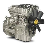
Perkins 1104D Troubleshooting Manual (228 pages)
Industrial Engines
Brand: Perkins
|
Category: Engine
|
Size: 2.66 MB
Table of Contents
-
Table of Contents
3
-
Troubleshooting Section
5
-
Electronic Troubleshooting
5
-
System Overview
5
-
Glossary
8
-
Electronic Service Tools
12
-
Indicator Lamps
14
-
Replacing the ECM
17
-
Self-Diagnostics
18
-
Sensors and Electrical Connectors
18
-
Engine Wiring Information
25
-
ECM Harness Connector Terminals
29
-
Programming Parameters
31
-
Test ECM Mode
31
-
ECM Snapshot
31
-
Factory Passwords
32
-
Factory Passwords Worksheet
33
-
Flash Programming
33
-
Injector Trim File
34
-
Mode Switch Setup
35
-
Throttle Setup
36
-
Multiposition Switch Setup
39
-
Customer Specified Parameters
41
-
Customer Specified Parameters Table
44
-
Customer Specified Parameters Worksheet
45
-
System Configuration Parameters
46
-
Troubleshooting Without a Diagnostic Code
47
-
Alternator Noise
47
-
Alternator will Not Charge
47
-
Battery
48
-
Can Not Reach Top Engine RPM
48
-
Coolant in Engine Oil
50
-
Coolant Temperature Is too High
51
-
ECM will Not Accept Factory Passwords
52
-
ECM will Not Communicate with Other Systems or Display Modules
52
-
Electronic Service Tool will Not Communicate with ECM
52
-
Engine Cranks but will Not Start
53
-
Engine Has Early Wear
56
-
Engine Misfires, Runs Rough or Is Unstable
56
-
Engine Oil in Cooling System
58
-
Engine Speed Does Not Change
59
-
Engine Stalls at Low RPM
60
-
Engine Vibration
61
-
Engine will Not Crank
62
-
Excessive Black Smoke
63
-
Excessive Engine Oil Consumption
65
-
Excessive Fuel Consumption
66
-
Excessive Valve Lash
68
-
Excessive White Smoke
68
-
Intake Air Temperature Is too High
69
-
Intermittent Engine Shutdown
71
-
Intermittent Low Power or Power Cutout
72
-
Low Engine Oil Pressure
73
-
Low Power/Poor or no Response to Throttle
74
-
Mechanical Noise (Knock) in Engine
76
-
Noise Coming from Cylinder
77
-
Troubleshooting with a Diagnostic Code
78
-
Diagnostic Code Cross Reference
78
-
No Diagnostic Codes Detected
80
-
CID 0001 Fmi 02
80
-
CID 0001 Fmi 05
81
-
CID 0001 Fmi 06
81
-
CID 0001 Fmi 07
82
-
CID 0002 Fmi 02
82
-
CID 0002 Fmi 05
83
-
CID 0002 Fmi 06
83
-
CID 0002 Fmi 07
84
-
CID 0003 Fmi 02
84
-
CID 0003 Fmi 05
84
-
CID 0003 Fmi 06
85
-
CID 0003 Fmi 07
85
-
CID 0004 Fmi 02
86
-
CID 0004 Fmi 05
86
-
CID 0004 Fmi 06
87
-
CID 0004 Fmi 07
87
-
CID 0005 Fmi 02
87
-
CID 0005 Fmi 05
88
-
CID 0005 Fmi 06
88
-
CID 0005 Fmi 07
89
-
CID 0006 Fmi 02
89
-
CID 0006 Fmi 05
90
-
CID 0006 Fmi 06
90
-
CID 0006 Fmi 07
91
-
CID 0041 Fmi 03
91
-
CID 0041 Fmi 04
92
-
CID 0091 Fmi 02
92
-
CID 0091 Fmi 03
93
-
CID 0091 Fmi 04
93
-
CID 0091 Fmi 08
94
-
CID 0100 Fmi 03
94
-
CID 0100 Fmi 04
95
-
CID 0100 Fmi 10
95
-
CID 0110 Fmi 03
96
-
CID 0110 Fmi 04
96
-
CID 0168 Fmi 00
96
-
CID 0168 Fmi 01
97
-
CID 0168 Fmi 02
97
-
CID 0172 Fmi 03
98
-
CID 0172 Fmi 04
98
-
CID 0190 Fmi 08
99
-
CID 0247 Fmi 09
99
-
CID 0247 Fmi 12
99
-
CID 0253 Fmi 02
100
-
CID 0261 Fmi 11
100
-
CID 0262 Fmi 03
100
-
CID 0262 Fmi 04
101
-
CID 0268 Fmi 02
101
-
CID 0342 Fmi 08
101
-
CID 0526 Fmi 05
102
-
CID 0526 Fmi 06
102
-
CID 0526 Fmi 07
102
-
CID 0774 Fmi 03
103
-
CID 0774 Fmi 02
103
-
CID 0774 Fmi 04
104
-
CID 0774 Fmi 08
105
-
CID 1639 Fmi 09
105
-
CID 1743 Fmi 02
105
-
CID 1779 Fmi 05
106
-
CID 1779 Fmi 06
106
-
CID 1785 Fmi 03
106
-
CID 1785 Fmi 04
107
-
CID 1785 Fmi 10
107
-
CID 1797 Fmi 03
108
-
CID 1797 Fmi 04
108
-
CID 1834 Fmi 02
108
-
CID 2246 Fmi 06
109
-
Troubleshooting with an Event Code
110
-
Event Codes
110
-
E172 High Air Filter Restriction
110
-
E194 High Exhaust Temperature
110
-
E232 High Fuel/Water Separator Water Level
111
-
E360 Low Engine Oil Pressure
111
-
E361 High Engine Coolant Temperature
113
-
E362 Engine Overspeed
114
-
E396 High Fuel Rail Pressure
115
-
E398 Low Fuel Rail Pressure
115
-
E539 High Intake Manifold Air Temperature
116
-
E2143 Low Engine Coolant Level
117
-
Diagnostic Functional Tests
118
-
Volt Sensor Supply Circuit — Test
118
-
Analog Throttle Position Sensor Circuit — Test
125
-
CAN Data Link Circuit — Test
130
-
Data Link Circuit — Test
133
-
Digital Throttle Position Sensor Circuit — Test
139
-
ECM Memory — Test
146
-
Electrical Connectors — Inspect
147
-
Engine Pressure Sensor Open or Short Circuit — Test
151
-
Engine Speed/Timing Sensor Circuit — Test
158
-
Engine Temperature Sensor Open or Short Circuit — Test
166
-
Fuel Rail Pump Solenoid — Test
171
-
Idle Validation Switch Circuit — Test
176
-
Ignition Keyswitch Circuit and Battery Supply Circuit — Test
181
-
Indicator Lamp Circuit — Test
187
-
Injector Data Incorrect — Test
190
-
Injector Solenoid Circuit — Test
192
-
Mode Selection Circuit — Test
202
-
PTO Switch Circuit — Test
206
-
Starting Aid (Glow Plug) Relay Circuit — Test
210
-
Throttle Switch Circuit — Test
213
-
Wastegate Solenoid — Test
217
-
Index
223
Advertisement
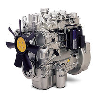
Perkins 1104D Operation And Maintenance Manual (112 pages)
Brand: Perkins
|
Category: Engine
|
Size: 3.89 MB
Advertisement
Related Products
-
Perkins 1104D-E44TA
-
Perkins 1104D-E44T
-
Perkins 1104
-
Perkins 1104E Series
-
Perkins 1104D NH1
-
Perkins 1104D NJ1
-
Perkins 1104AA-44TG
-
Perkins 1106C-E70TA
-
Perkins 1106E Series
-
Perkins 1106AA-70TAG3
Perkins Categories
Engine
Lifting Systems
Personal Care Products
Inverter
Speakers
More Perkins Manuals
Each Perkins engine has its own Operation and Maintenance Manual (RETO / OMM). This provides all the necessary information so that your engine runs normally day after day. It contains detailed
information on regular maintenance intervals along with technical data and instructions.
Perkins issues Operation and Maintenance Manuals (OMMs) for each engine type. Each manual is divided into four sections, which cover:
- security,
- product information,
- exploitation,
- maintenance — this part contains information on the capacity of refueling containers, recommendations for liquids, schedules for maintenance intervals and maintenance procedures
The first letters of the engine serial number are the engine family and type code. They can be found on the engine data plate or in the sales order confirmation.
Perkins is a subsidiary of Caterpillar and manufactures engines used in:
- agricultural machinery
- vehicles
- building
- electricity generation
- industry.
Perkins engines can be both diesel and gas.
Example: 1206E-E66TA (G)
1206E-E66TA (G) 12 = Series. (12 = 1200 series)
1206E-E66TA (G) 06 = Number of cylinders
1206E-E66TA (G) (Emissions Compliancy) Emission Compliance
1206E-E66TA (G) (Electronic Fuel Injection) Electronic Injector
1206E-E66TA (G) Capacity in liters. (6.6 liter)
1206E-E66TA (G) Supercharging: T = Turbo, A = Air — air cooling, W = Water — water cooling.
1206E-E66TA (G) Generator Set Rating
Perkins 2806D-E18TA
Industrial Engine – PDF Service Manual
Perkins 2806F-E18TA
Industrial Engine – PDF Service Manual
PERKINS 4-108 SHOP
MANUAL
Perkins 400 Series
4016-E61TRS (Models 403C-11, 403C-15, 404C-22 and 404C-22T)
Perkins 4000 Series
(4006-23 TAG1A, TAG2A and TAG3A Inline diesel engine)
Perkins 4000 Series Diesel
Engine – PDF Service Manual
Perkins 4000 Series Inline
diesel engine – PDF Service Manual
Perkins 4006 and 4008
Diesel engine – PDF Service Manual
Perkins 4006 TRS Gas and
4008 TRS Gas Industrial Engines – PDF Service Manua
Perkins 4006 TRS Gas and
4008 TRS GasIndustrial Engines Workshop Manual
Perkins 4006-23 and 4008-30
Industrial Engine – PDF Service Manual
Perkins 400A and 400D Industrial Engine – PDF Service Manual
Perkins 4012-46A Industrial
Engine – PDF Service Manual
Perkins 4016-61 TRG
Industrial Engine – PDF Service Manual
Perkins 4016-61TRS1 and
4016-61TRS2 Gas Engines – PDF Service Manual
Perkins 402D-403D-404D
Industrial Engine Disassembly and Assembly Manual
Perkins 402D-403D-404D
Industrial Engine PDF Service manual
Perkins 402F-05, 403F-07,
403F-11, and 403F-15 Industrial Engines – PDF Service Manual
Perkins 403F-15T, 404F-22
and 404F-22T Industrial Engines – PDF Service Manual.
Perkins 404A-22SG1 Gas
Industrial Engine – PDF Service Manual
Perkins 404F-E22T,
404F-E22TA and 403F-E17T Industrial Engines – PDF Service Manual
Perkins 800D Series
Industrial Engines – PDF Service Manual
Perkins 854E-E34TA and
854F-E34T Industrial Engine – PDF Service Manual
Perkins 854F-E34TA
Industrial Engine – PDF Service Manual
Perkins DIAG1300 User
manual.
Perkins Diesel Engine 4-154
Workshop Manual.
Perkins Engine Fault
Finding Guide.
Perkins Engine Number
Guide.
Perkins Phaser 4 – and
6-cylinder Workshop Manual
Perkins TIER2 DIESEL
ENGINES 1100 (VK) Workshop Manual
Perkins TPD1352 – PDF
Service Manual
The codes refer to the
model range of engines Perkins
Workshop Manual for Perkins
4.108, 4.107 and 4.99 diesel engines
Workshop Manual for Perkins
4.108M, 4.107M and 4.99M diesel engines
В настоящем издании описаны двигатели Perkins 1104D-E44TA, которые устанавливаются на тракторы (Massey Ferguson), экскаваторы-погрузчики (Terex), экскаваторы (Тверской экскаватор), асфальтоукладчики (Vogele), вилочные телескопические погрузчики (Manitou, Merlo), траншеекопатели, электрогенераторы и другую спецтехнику. Двигатели Perkins 1104D-E44TA – четырехцилиндровые дизельные двигатели с рабочим объемом 4,4 л, с четырьмя клапанами на цилиндр, с топливным коллектором Common Rail, с электронным управлением впрыском.
Содержание
Спецификации
Топливопроводы высокого давления
Топливный насос высокого давления
Форсунка
Головка топливного фильтра (двойной фильтр)
Подкачивающий топливный насос (механический)
Подкачивающий топливный насос (электрический)
Топливный коллектор COMMON RAIL
Толкатель клапана
Вал коромысел
Клапанная крышка
Клапаны
Головка блока цилиндров
Турбонагнетатель
Выпускной коллектор
Распредвал
Подшипник распредвала
Головка масляного фильтра
Маслоохладитель
Масляный насос, двигатели с блоком балансиров
Масляный насос, двигатели без блока балансиров
Давление моторного масла
Перепускной клапан моторного масла (на масляном насосе)
Перепускной клапан моторного масла (на блоке балансиров)
Масляный поддон
Сапун картера (без фильтра)
Сапун картера (с фильтром)
Термостат
Насос охлаждающей жидкости
Блок цилиндров
Коленвал из чугуна с шаровидным графитом (SGI)
Сальник коленвала
Шейки подшипников шатунов
Шатунные подшипники (стандарт)
Коренные подшипники (стандарт)
Шатун
Поршни и поршневые кольца
Поршень
Маслораспылитель охлаждения поршня
Блок балансиров
Передний картер и крышки
Передняя группа шестерен
Маховик.
Картер маховика
Шкив коленвала
Шкив коленвала для многоручьевого ремня
Натяжитель ремня
Компрессор кондиционера
Привод вентилятора
Подъемные кронштейны
Генератор (12 В и 24 В, тип 1)
Кронштейн генератора
Стартер
Датчик температуры охлаждающей жидкости
Датчик температуры моторного масла
Датчик давления воздуха наддува
Датчик температуры во впускном коллекторе
Датчик оборотов/момента газораспределения
Блок управления двигателя
Свечи предпускового подогрева
Снятие и установка компонентов Топливоподкачивающий насос (электрический), топливный фильтр и водоотделитель
Топливоподкачивающий насос (механический)
Регулятор расхода топлива
Головка топливного фильтра
Топливный коллектор COMMON RAIL
Топливопроводы высокого давления
Один топливопровод высокого давления между топливным коллектором и форсункой
Все топливопроводы высокого давления между топливным коллектором И форсунками и топливным насосом высокого давления
Топливный насос высокого давления
Шестерня топливного насоса высокого давления
Форсунки
Турбокомпрессор, боковое расположение
Турбокомпрессор, верхнее расположение
Выпускной коллектор с верхним расположением фланца
Выпускной коллектор с боковым расположением фланца
Выпускное колено турбокомпрессора
Клапанные пружины
Клапаны
Головка масляного фильтра
Маслоохладитель
Редукционный клапан системы смазки
Конструкция двигателя без блока балансиров
Конструкция двигателя с блоком балансиров
Масляный насос системы смазки
Насос охлаждающей жидкости
Термостат
Маховик
Задний сальник коленвала
Картер маховика
Шкив коленвала
Передний сальник коленвала
Передняя крышка
Передняя группа шестерен
Промежуточная шестерня
Передний картер
Привод вспомогательных агрегатов (SAE «B»)
Привод вспомогательных агрегатов (SAE «А»)
Сапун картера (без фильтра)
Сапун картера (с фильтром)
Клапанная крышка
Основание клапанной крышки
Ось коромысел и штоки толкателей клапанов
Головка блока цилиндров
Толкатели клапанов
Распределительный вал
Шестерня распределительного вала
Подшипник распределительного вала
Поддон картера (из чугуна)
Поддон картера (из алюминия или штампованной стали)
Блок балансиров
Маслораспылитель охлаждения поршня
Шатуны и поршни
Коленчатый вал
Кольцо синхронизации коленчатого вала
Шестерня коленчатого вала
Компрессор кондиционера
Датчик положения коленчатого вала
Вспомогательный датчик оборотов коленчатого вала/положения Коленчатого вала
Датчик температуры охлаждающей жидкости
Датчик давления моторного масла
Датчик давления топлива
Датчик температуры воздуха на входе
Свечи предпускового подогрева
Ремень привода генератора и натяжитель
Вентилятор
Привод вентилятора
Электронный блок управления
Монтажный кронштейн электронного блока управления
Генератор
Стартер
Воздушный компрессор
Проверки и регулировки Наличие воздуха в топливе, проверка
Установка поршня цилиндра № 1 в ВМТ
Синхронизация впрыска топлива, проверка
Компрессия, проверка
Клапанные зазоры, проверка и регулировка
Заглубление клапана
Направляющая клапана, осмотр
Масляный насос, измерение зазоров
Поршневое кольцо, измерение зазоров
Биение лицевой поверхности маховика
Биение боковой поверхности маховика
Биение картера маховика
Центровка картера маховика
Генератор, проверка
Генератор, проверка зарядки аккумулятора
Электрическая система пуска, проверка
Коды неисправностей
Самодиагностика
Мигающие коды
Коды неисправностей J1939
Коды неисправностей PDL (PERKINS DIAGNOSTIC LINK)
Таблица взаимного соответствия кодов PDL, кодов J1939 и мигающих кодов
Техническое обслуживание
Регламент технического обслуживания
По мере необходимости
Ежедневно
Еженедельно
Каждые 50 моточасов или еженедельно
Каждые 400 моточасов
Начальные 500 моточасов
Каждые 500 моточасов
Каждые 500 моточасов или ежегодно
Каждые 1000 моточасов
Каждые 2000 моточасов
Каждые 3000 моточасов
Каждые 3000 моточасов или каждые 2 года
Каждые 4000 моточасов
Каждые 6000 моточасов или каждые 3 года
Каждые 12 000 моточасов или каждые 6 лет
Приемка
Описание некоторых процедур технического обслуживания
Замена охлаждающей жидкости
Сливная пробка охлаждающей жидкости блока цилиндров
Замена моторного масла и масляного фильтра
Зазор кожух/вентилятор
Топливная система – прокачка
Ручной подкачивающий насос
Электрический подкачивающий насос
Оставить отзыв
Ваше Имя:
Ваш отзыв:
Введите код, указанный на картинке:

Снятие и установка компонентов
Масляный насос системы смазки
- Снимите масляный поддон.
- Если линия всасывания (5) оборудована опорным кронштейном, выверните болт (7) из кронштейна (8). Момент затяжки болта (7) при установке 44 Нм (32 фунт-фута).
- Ослабьте затяжку болта (6) стопорного зажима. Момент затяжки при установке 22 Нм (16 фунт-футов).
- Снимите кронштейн (8).
Внимание!
Отметьте положение и ориентацию деталей опорного кронштейна.
- Снимите болты (4) с линии всасывания (1). Момент затяжки при установке 22 Нм (16 фунт-футов).
- Снимите линию всасывания (5) с масляного насоса (2).

- Снимите прокладку (3) (не показана).
- Выверните болты (1). Момент затяжки при установке 22 Нм (16 фунт-футов). Снимите узел.
- Выверните болты (11). Момент затяжки при установке 22 Нм (16 фунт-футов).
- Снимите узел передней крышки (12) с узла масляного насоса двигателя (2).
- Нанесите временную метку на наружный ротор (13) для последующей сборки.
- Снимите наружный ротор с масляного насоса двигателя (2).
- Не снимайте штифты (9) и (10) с корпуса масляного насоса двигателя, если они не повреждены.
- Установка производится в последовательности, обратной снятию. После сборки проверьте люфты и зазоры в зацеплении шестерен, см. раздел «Спецификации».

Другие книги по ремонту и обслуживанию двигателей:
- руководство по ремонту двигателей Diesel Daimler Chrysler Series MBE 4000
- книги по ремонту двигателей Cummins ISF 2.8
- инструкция по эксплуатации двигателей Caterpillar C9
Автомобильная литература