- Артикул: 5243 — назовите при заказе по телефону
- Издательство: СпецИнфо
- ISBN: 966267205-2
- Число страниц: 90
- Формат: А5
- Переплет: Мягкий
Цена в интернет-магазине: 1 899 руб.
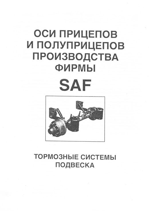
Книга Оси прицепов и полуприцепов САФ серий SK500, SK 500 Plus, SK RS, SK RB, RBM, WRZM, SBK, SNK, SNF, SK RS, RZ, K, SK RLS. Каталог деталей. Руководство по характеристикам, ремонту и обслуживанию тормозных систем и подвески.
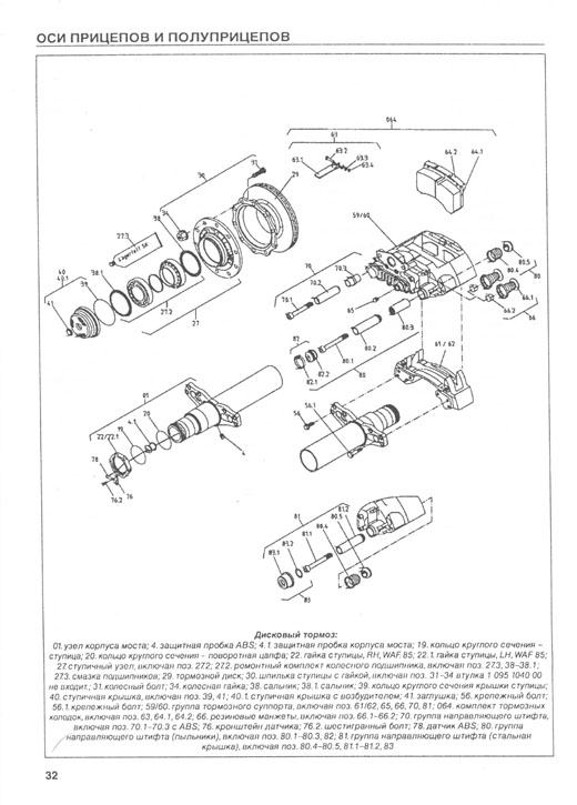
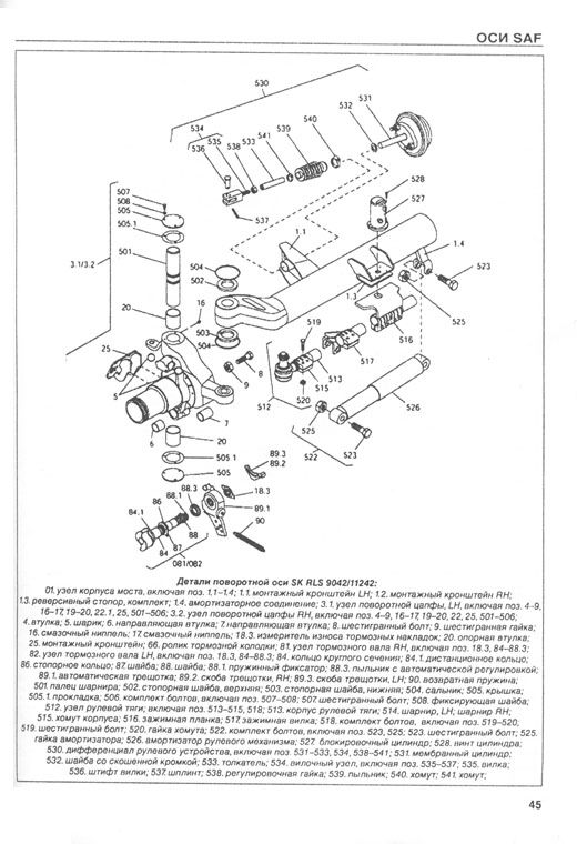
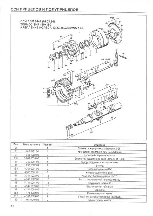
В настоящем издании представлено руководство по техническому обслуживанию и ремонту, а также каталоги основных деталей осевых агрегатов прицепов и полуприцепов производства SAF серии SK 500, SK 500 Plus, SK RS, SK RB, RBM, WRZM, SBK, SNK, SNF, SK RS/RZ/K, SK RLS.
Книга будет полезна всем владельцам грузовых автомобилей, специалистам, работающим в области авторемонта, а также всем интересующимся грузовой автотехникой.
В книге доступно описано техническое обслуживание тормозов и пневматики прицепа и полуприцепа SAF, представлен ремонт и каталог деталей прицепной техники фирмы SAF серии SK 500, SK 500 Plus, SK RS, SK RB, RBM, WRZM, SBK, SNK, SNF, SK RS/RZ/K, SK RLS.
Купить книгу по ремонту и обслуживанию осей прицепов и полуприцепов SAF серий SK500, SK 500 Plus, SK RS, SK RB, RBM, WRZM, SBK, SNK, SNF, SK RS, RZ, K, SK RLS, каталог деталей Вы можете в нашем интернет-магазине с доставкой Почтой России или курьером по Москве.
Интернет-портал Легион-Автодата создан для удобных покупок: автолитературы, программ для диагностики автомобиля, диагностических приборов, адаптеров elm327, автоаксессуаров и инструментов для авторемонта. Купить книги и приборы для диагностики и ремонта автомобиля Вы можете в нашем интернет магазине.
Удобно оплатить руководства по ремонту и эксплуатации выбранных Вами марок авто любой из платежных систем.
Заказать доставку автокниги почтой без предоплаты, курьером по Москве, регионам и в более 200 пунктов самовывоза по всей России.
-
Содержания книг
- Руководство по ремонту осей прицепов, полуприцепов SAF, BPW, ROR
ИДЕНТИФИКАЦИЯ МОСТОВ И ПОДВЕСКИ ФИРМЫ SAF 5
ВЫБОР НАИБОЛЕЕ ПОДХОДЯЩЕЙ КОМБИНАЦИИ ТРАНСПОРТНОГО СРЕДСТВА {ТЯГАЧ + ПОЛУПРИЦЕП) 6
МОСТ SAFSK 500 6
КОМПОНЕНТЫ МОСТА SAF SK 500 7
РУКОВОДСТВО ПО ОБСЛУЖИВАНИЮ МОСТОВ SAF SK 500 8
ТРЕБОВАНИЯ SAF 8
ОСИ SK 500 PLUS, SK RS 9042 И МОСТ НОВОГО ПОКОЛЕНИЯ SK 500 PLUS ET 0 9
РЕГУЛИРОВКА ЛЮФТА СТУПИЧНЫХ ПОДШИПНИКОВ, СМАЗКА 9
СПЕЦИФИКАЦИЯ СМАЗКИ 9
ТОРМОЗНОЙ МЕХАНИЗМ SNK 420 11
РЕМОНТ ТОРМОЗОВ 11
ТОРМОЗНЫЕ НАКЛАДКИ 15
ЗАМЕНА ТОРМОЗНЫХ НАКЛАДОК 15
ТОРМОЗНОЙ БАРАБАН 16
УСТАНОВКА ТОРМОЗНЫХ КОЛОДОК 17
ПРОТОЧКА ТОРМОЗНЫХ НАКЛАДОК 18
УСТАНОВКА СТУПИЦЫ КОЛЕСА С ТОРМОЗНЫМ БАРАБАНОМ 19
РЕМОНТ КОЛЕСНЫХ ПОДШИПНИКОВ 21
РЕГУЛИРОВКА ПОДШИПНИКОВ КОЛЕСА РАЗЛИЧНЫХ ТИПОВ ОСЕЙ 23
БАРАБАННЫЕ ТОРМОЗА, КОНТРОЛЬ И РЕГУЛИРОВКА 24
ПРОВЕРКА УСТАНОВКИ УГЛОВ КОЛЕС 26
ПОЛУПРИЦЕП С ЗАДНИМ УПРАВЛЯЕМЫМ МОСТОМ 27
ПРИЦЕП 27
ИНСТРУКЦИЯ ПО ЗАТЯЖКЕ БОЛТА ВТУЛКИ ПОЛУРЕССОРЫ 28
ПНЕВМАТИЧЕСКАЯ ПОДВЕСКА 28
РЕГУЛИРОВКА УРОВНЯ ПЛАТФОРМЫ 28
АВТОМАТИЧЕСКИЙ РЫЧАГ ТИПА S-ABA 29
ПРОВЕРКА ФУНКЦИОНИРОВАНИЯ 29
ДИСКОВЫЕ ТОРМОЗА 30
ОСОБЕННОСТИ ДИСКОВЫХ ТОРМОЗОВ 30
ПОИСК НЕИСПРАВНОСТЕЙ ДИСКОВЫХТОРМОЗОВ 30
ОБСЛУЖИВАНИЕ ОСЕЙ SK RS/RZ 9022 К/11222 К (22.5″) 9019 К/11019 К (19.5″) 31
ПРОВЕРКА АВТОМАТИЧЕСКОГО МЕХАНИЗМА РЕГУЛИРОВКИ ЗАЗОРА 33
ПРОВЕРКА ТОРМОЗНЫХ КОЛОДОК 33
РЕМОНТ ТОРМОЗОВ 34
ПОВОРОТНЫЕ ОСИ SAF SK RLS 9042/11242 43
РЕГУЛИРОВКА ЗАДНЕЙ ПОВОРОТНОЙ ОСИ 44
КАТАЛОГ ДЕТАЛЕЙ ОСЕЙ SAF 46
ОСИ SK 1000 ЕТ С 01.02.98 46
ОСИ SKRS 9042 15.02.98 49
ОСИ SK RZ 9030 15.02.98 50
ОСИ RBM 8442 01. 03.94 52
ОСИ RLSM8442 15.02.92 54
ОСИ SKRLS 9042 15.02.98 58
OCИ WRZM 11035-10 01.03.94 62
ОСИ SK RS 11019 К 64
OCИ SKRB9022K 66
ПНЕВМОПОДВЕСКА Еи416Н 68
ПНЕВМОПОДВЕСКА М 70
ПНЕВМОПОДВЕСКА АР311/ЕМ311 74
ПНЕВМОПОДВЕСКА AR 211 76
ПНЕВМОПОДВЕСКА AR 213 78
ПНЕВМОПОДВЕСКА AR 313 80
ПНЕВМОПОДВЕСКА AR316/EU316 82
ПНЕВМОПОДВЕСКА AR 413 84
ПНЕВМОПОДВЕСКА U 86
ТЕХНИЧЕСКИЕ ХАРАКТЕРИСТИКИ, ОБСЛУЖИВАНИЕ И РЕМОНТ ОСЕЙ BPW 93
СЕРВИС BPW 93
ИНСТРУКЦИЯ ПО СЕРВИСУ 94
ОСМОТР ПОСЛЕ ПРИЕМА В ЭКСПЛУАТАЦИЮ 94
ОСИ BPW ДЛЯ ПРИЦЕПОВ 96
ПНЕВМОПОДВЕСКИ ВРW 102
ОСЕВЫЕ АГРЕГАТЫ BPW СЕРИИ VA.VB.VG 106
ОСЕВЫЕ АГРЕГАТЫ BPW СЕРИИ W, BW, GW 109
БАЛКИ ОСЕЙ, КРОНШТЕЙНЫ ТОРМОЗА 110
ОПРЕДЕЛЕНИЕ ТИПА БАЛОК ОСЕЙ ПРИ ЗАМЕНЕ 110
КАТАЛОГ ДЕТАЛЕЙ ОСЕЙ BPW 112
ОСИ Н / КН СТАНД./ЕСО ТОРМОЗ-1/2 112
ОСИ Н / КН ECO/ECOWuiТОРМОЗ С УПОРНЫМ РОЛИКОМ (BPW 95) 112
ТОРМОЗНОЙ ВАЛ И ПОДШИПНИКИ 114
OCHN 118
ОСИН / К 118
ТРЕЩОТКИ 123
РУЧНАЯ ТРЕЩОТКА GSK, ВОЗВРАТНЫЕ ПРУЖИНЫ 124
АВТОМАТИЧЕСКИЕ ТРЕЩОТКИ ECO-MASTER 125
ТРЕЩОТКИ ECO-MASTER- ОСИ СЕРИЙ H /R 126
ТРЕЩОТКИ ECO-MASTER-ОСИ СЕРИЙ КН /KR 127
ТРЕЩОТКИ ECO-MASTER-ОСИ СЕРИЙ NH /NR 128
ИНСТРУКЦИИ ПО УСТАНОВКЕ ECO-MASTER 129
КРЕПЛЕНИЕ ТРЕЩОТКИ 130
ДЕТАЛИ ТОРМОЗА 132
БАРАБАННЫЕ ТОРМОЗА BPW 132
ДЕТАЛИТОРМОЗА SN 42 2 132
ДЕТАЛИТОРМОЗА SN 36 134
ДЕТАЛИТОРМОЗА SN 30 136
ДЕТАЛИТОРМОЗА SN 42 С УПОРНЫМ РОЛИКОМВ PW 95 138
ДЕТАЛИТОРМОЗА SN 36 С УПОРНЫМ РОЛИКОМВ PW 95 139
ДЕТАЛИ ТОРМОЗА SN 30 С УПОРНЫМ РОЛИКОМВ PW 95 140
ТОРМОЗНОЙ БАРАБАН SN 42 H /R 141
ТОРМОЗНОЙ БАРАБАН SN 36 КН /KR 142
ТОРМОЗНОЙ БАРАБАН SN 30 NH /NR 142
КРЕПЛЕНИЕ ТОРМОЗНОГО БАРАБАНА 143
ТОРМОЗНЫЕ ЩИТЫ 144
ТОРМОЗНОЙ ЦИЛИНДР 146
ПОДШИПНИКИ СТУПИЦЫ, УПЛОТНЕНИЯ СТУПИЦЫ 147
ПОДШИПНИКИ СТУПИЦЫ BPW 147
СТУПИЦА ECO/ECO MAXX 154
СТУПИЦА ЕСО*-1 156
СТАНДАРТНЫЙ ПОДШИПНИК СТУПИЦЫ 158
СМАЗКА СТУПИЦЫ КОЛЕСА, РЕГУЛИРОВКА ПОДШИПНИКА 162
ПРИСПОСОБЛЕНИИ ДЛЯ СМАЗКИ КОНИЧЕСКИХ РОЛИКОПОДШИПНИКОВ 165
ДЕТАЛИ ABS 165
ОБШАЯ ИНФОРМАЦИЯ 165
ОСИН /R 166
КОМПЛЕКТЫ ДЛЯ МОДЕРНИЗАЦИИ 166
ОСИКН /KR 168
КОМПЛЕКТ ДЛЯ МОДЕРНИЗАЦИИ 169
ОСИ NH /NR 170
КОМПЛЕКТЫ ДЛЯ МОДЕРНИЗАЦИИ ABS 173
CHCTEMATRILEX 174
КОЛЕСНЫЕ ШПИЛЬКИ 176
ОДИНАРНЫЕ КОЛЕСА 178
ДВОЙНЫЕ КОЛЕСА 181
КОЛПАКИ СТУПИЦЫ СО ВСТРОЕННЫМ СЧЕТЧИКОМ ПРОБЕГА 184
ТЕХНИЧЕСКИЕ ХАРАКТЕРИСТИКИ, ОБСЛУЖИВАНИЕ И РЕМОНТ ОСЕЙ ROR 189
OCMLM, LMC 189
ОПРЕДЕЛЕНИЕ ТИПА ОСИ 189
ИДЕНТИФИКАЦИЯ СЕРИЙНОГО НОМЕРА 189
ТЕХОБСЛУЖИВАНИЕ ОСЕЙ LM, LMC BP LS EP2 190
РЕКОМЕНДУЕМЫЕ СМАЗКИ 191
ТЕХНИЧЕСКОЕ ОБСЛУЖИВАНИЕ БАРАБАННЫХ ТОРМОЗОВ LM/LMC 191
ТЕХНИЧЕСКОЕ ОБСЛУЖИВАНИЕ ДИСКОВЫХТОРМОЗОВ LM/LMC 195
ПРОВЕРКА ТОРМОЗНОГО ДИСКА 197
ДЕМОНТАЖ И ЗАМЕНА СУППОРТА 198
ТЕХНИЧЕСКОЕ ОБСЛУЖИВАНИЕ СТУПИЦЫ LM С БАРАБАННЫМИ ТОРМОЗАМИ 198
ОСИТМ 201
ОПРЕДЕЛЕНИЕ ТИПА ОСИ 201
БАЛКА ОСИ 202
ТЕХНИЧЕСКИЕ ХАРАКТЕРИСТИКИ ОСЕЙ ТМ 202
ТЕХНИЧЕСКОЕ ОБСЛУЖИВАНИЕ БАРАБАННЫХ ТОРМОЗОВ СЕРИИ ТМ 203
ТОРМОЗНОЙ ВАЛ И ВТУЛКИ 205
КАПИТАЛЬНЫЙ РЕМОНТ СТУПИЦЫ 207
ЭКСПЛУАТАЦИОННЫЕ НЕИСПРАВНОСТИ ТОРМОЗНОЙ СИСТЕМЫ ОСИ (БАРА6АННЫЙ ТОРМОЗ) 209
ПНЕВМОПОДВЕСКА 211
ИДЕНТИФИКАЦИЯ ТИПА ПОДВЕСКИ 211
ИДЕНТИФИКАЦИЯ СЕРИЙНОГО НОМЕРА 211
ТЕХНИЧЕСКОЕ ОБСЛУЖИВАНИЕ ПНЕВМОПОД8ЁСКИ 212
СНЯТИЕ И УСТАНОВКА ПНЕВМОПОДУШЕК 213
СНЯТИЕ И ЗАМЕНА АМОРТИЗАТОРОВ МОДЕЛИ FLEXAIR 215
СНЯТИЕ И ЗАМЕНА АМОРТИЗАТОРОВ МОДЕЛИ FLEXLITE 215
СНЯТИЕ И ЗАМЕНА ОСИ 216
СНЯТИЕ И ЗАМЕНА ПРОДОЛЬНЫХ РЫЧАГОВ ПОДВЕСКИ МОДЕЛЕЙ FLEXAIR И FLEXLITE 217
ЗАМЕНА ШАРНИРНЫХ ВТУЛОК 218
ПОВТОРНОЕ ЦЕНТРИРОВАНИЕ ОСИ (ТРЕКИНГ) 218
ЭКСПЛУАТАЦИОННЫЕ НЕИСПРАВНОСТИ 219
МЕХАНИЧЕСКАЯ ПОДВЕСКА SMT MERITOR 221
ТАБЛИЦА СООТВЕТСТВИЯ НАГРУЗОК 221
ИДЕНТИФИКАЦИЯ ПОДВЕСКИ 221
ТЕХНИЧЕСКОЕ ОБСЛУЖИВАНИЕ 221
КАТАЛОГ ДЕТАЛЕЙ ОСЕЙ ROR 224
OCMLM 224
ДЕТАЛИ СТУПИЦЫ 224
ТОРМОЗНЫЕ КУЛАЧКОВЫЕ ВАЛЫ 226
ТОРМОЗНЫЕ ЭЛЕМЕНТЫ 228
ЭЛЕМЕНТЫ СИСТЕМЫ ABS 229
ДЕТАЛИ ТОРМОЗНОГО ВАЛА 230
ОСИ LM СО СТУПИЦЕЙ DX195 232
ТОРМОЗНОЙ ДИСК И ЧАСТИ СИСТЕМЫ ABS 232
ОСИ LMDX195 234
ТОРМОЗНЫЕ ЭЛЕМЕНТЫ 234
АКТИВАТОРЫ И ВОЗДУШНЫЕ КАМЕРЫ 235
OCHLMC 236
ДЕТАЛИ СТУПИЦЫ 236
OCMLMDX195 237
ЗАМЕНЯЕМЫЕ ЧАСТИ 237
ОСИТА 238
ДЕТАЛИ СТУПИЦЫ 238
ТОРМОЗНЫЕ ЭЛЕМЕНТЫ 240
ДЕТАЛИ ABS 241
ТОРМОЗНОЙ ВАЛ 242
ОСИТА DDUCO 246
СТУПИЦА. ТОРМОЗНОЙ ДИСК И ABS 246
ОСИ ТАС 248
ДЕТАЛИ СТУПИЦЫ 248
OCИ D DUCO 249
ТОРМОЗНЫЕ ЭЛЕМЕНТЫ 249
ВОЗДУШНЫЕ КАМЕРЫ 250
ОСИТМ 251
ИДЕНТИФИКАЦИЯ ТИПА ОСИ И СЕРИЙНОГО НОМЕРА 251
ЭЛЕМЕНТЫ СИСТЕМЫ ABS 252
ТОРМОЗНЫЕ ЭЛЕМЕНТЫ 253
ДЕТАЛИ СТУПИЦЫ 254
ТОРМОЗНОЙ ВАЛ 256
РАЗМЕРЫ ТОРМОЗНЫХ ВАЛОВ 258
ТОРМОЗНОЙ ВАЛ 260
ОСИ ТМ DX195 262
СТУПИЦА, ТОРМОЗНОЙ ДИСК И ЭЛЕМЕНТЫ СИСТЕМЫ ABS 262
ВОЗДУШНЫЕ ТОРМОЗНЫЕ КАМЕРЫ 265
ОСИ ТЕ 266
ИДЕНТИФИКАЦИЯ ТИПА ОСИ И СЕРИЙНОГО НОМЕРА 266
ТОРМОЗНОЙ ВАЛ 267
ТОРМОЗНЫЕ ЭЛЕМЕНТЫ 268
ДЕТАЛИ СИСТЕМЫ ABS 269
КАТАЛОГ ДЕТАЛЕЙ СТУПИЦЫ 270
ПНЕВМОПОДВЕСКА ОСЕЙ 272
ПНЕВМОПОДВЕСКА ОСЕЙ XL9000 272
ПНЕВМОПОДВЕСКА ОСЕЙ XL9000L 273
ПНЕВМОПОДВЕСКА ОСЕЙ XL9000H 274
ПНЕВМОПОДВЕСКА ОСЕЙ XL9000HL 275
ПНЕВМОПОДВЕСКА ОСЕЙ FL9000NB 276
ПНЕВМОПОДВЕСКА ОСЕЙ FL9000 278
ПНЕВМОПОДВЕСКА ОСЕЙ FL9000L 280
ПНЕВМОПОДВЕСКА ОСЕЙ FL9000H 232
ПНЕВМОПОДВЕСКА ОСЕЙ FL9000HL 284
ПНЕВМОПОДВЕСКА ОСЕЙ FL9000HLL 286
ПНЕВМОПОДВЕСКА ОСЕЙ FL9000M 288
ПНЕВМОПОДВЕСКА ОСЕЙ FL11000 290
ПНЕВМОПОДВЕСКА ОСЕЙ FP11000 292
ПНЕВМОПОДВЕСКА ОСЕЙ FL11000L 294
ПНЕВМОПОДВЕСКА ОСЕЙ FL110O0/150 296
ПНЕВМОПОДВЕСКА ОСЕЙ FL11000D 298
ПНЕВМОПОДВЕСКА ОСЕЙ FL11000B 300
ПНЕВМОПОДВЕСКА ОСЕЙ FL11O00LB 302
ПНЕВМОПОДВЕСКА ОСЕЙ FL11000CT 304
ПНЕВМОПОДВЕСКА ОСЕЙ FL11000CS 305
ПНЕВМОПОДВЕСКА ОСЕЙ FL11000LS 306
ПНЕВМОПОДВЕСКА ОСЕЙ FL11000S 308
ПНЕВМОПОДВЕСКА ПОДЪЕМНОЙ ОСИ 310
ДВУСТОРОНИЙ ПОДЪЕМНИК 311
ПОДЪЕМНИК 312
ДИСКОВЫЕ ТОРМОЗА ФИРМЫ KNQRR
ТЕХНИЧЕСКИЕ ХАРАКТЕРИСТИКИ, ОБСЛУЖИВАНИЕ И ДЕТАЛИ ТОРМОЗОВ KNORR 315
ПЕРЕЧЕНЬ КОНСТРУКТИВНЫХ ЭЛЕМЕНТОВ 315
ДИСКОВЫЕ ТОРМОЗНЫЕ МЕХАНИЗМЫ СТАНДАРТНОГО И РАДИАЛЬНОГО ИСПОЛНЕНИЙ 319
ОПИСАНИЕ КОНСТРУКЦИИ И ПРИНЦИП ДЕЙСТВИЯ 320
ТЕХНИКА БЕЗОПАСНОСТИ ПРИ ПРОВЕДЕНИИ РЕМОНТНЫХ РАБОТ НА ДИСКОВЫХ ТОРМОЗНЫХ
МЕХАНИЗМАХ 322
ПРОВЕРКА ДИСКОВЫХ ТОРМОЗНЫХ МЕХАНИЗМОВ 322
ЗАМЕНА ТОРМОЗНЫХ КОЛОДОК 327
ЗАМЕНА УПОРОВ С ГОФРИРОВАННЫМИ ПЫЛЬНИКАМИ 329
РЕМОНТ РАЗГЕРМЕТИЗАЦИИ ПОДВИЖНОЙ СКОБЫ С ИСПОЛЬЗОВАНИЕМ «КОМПЛЕКТА УПЛОТНИТЕЛЬНЫХ ЭЛЕМЕНТОВ ДЛЯ НАПРАВЛЯЮЩИХ 330
РЕМОНТ ПОДВИЖНОЙ СКОБЫ С ИСПОЛЬЗОВАНИЕМ «КОМПЛЕКТА НАПРАВЛЯЮЩИХ ВТУЛОК И ГИЛЬЗ 331
ЗАМЕНА ПОДВИЖНОЙ СКОБЫ 332
ЗАМЕНА СУППОРТА 333
ЗАМЕНА ТОРМОЗНОГО ЦИЛИНДРА 333
ПНЕВМАТИЧЕСКАЯ АРМАТУРА ПРИЦЕПОВ И ПОЛУПРИЦЕПОВ WABCO~ ТЕХНИЧЕСКИЕ ХАРАКТЕРИСТИКИ, ОБСЛУЖИВАНИЕ И ДЕТАЛИ ПНЕВМАТИЧЕСКОЙ АРМАТУРЫ WABCO 337
ТОРМОЗНЫЕ КЛАПАНЫ ПРИЦЕПОВ 337
МАГИСТРАЛЬНЫЕ ФИЛЬТРЫ И КЛАПАНЫ РАСТОРМАЖИВАЙ И Я 339
ТОРМОЗНЫЕ КРАНЫ ПРИЦЕПОВ 340
КЛАПАНЫ ОГРАНИЧЕНИЯ ДАВЛЕНИЯ 343
УСКОРИТЕЛЬНЫЕ КЛАПАНЫ 344
РАЗОБЩАЮЩИЙ КЛАПАН И КЛАПАН БЫСТРОГО РАСТОРМАЖИВАНИЯ 344
КЛАПАН СООТНОШЕНИЯ ДАВЛЕНИЙ 345
МАГНИТНЫЕ КЛАПАНЫ 346
ТОРМОЗНОЙ КРАН ПРИЦЕПА СО ВСТРОЕННЫМ РЕГУЛЯТОРОМ ТОРМОЗНЫХ СИЛ (РТС) 347
ТОРМОЗНОЙ КРАН ПРИЦЕПА СО ВСТРОЕННЫМ РЕГУЛЯТОРОМ ТОРМОЗНЫХ СИЛ (РТС) 348
АВТОМАТИЧЕСКИЕ РЕГУЛЯТОРЫ ТОРМОЗНЫХ СИЛ 349
© Автолитература 2008
Все материалы, опубликованные на сайте http://avtoliteratura.ru, фотоизображение или тексты, являются объектом авторского права. Торговые знаки и логотипы, а так же авторские и смежные права принадлежат их законным владельцам. Частичное или полное копирование текстов, слоганов и фотоизображений без письменного согласия владельцев сайта запрещено и влечет за собой ответственность согласно действующему законодательству
Главное отличие нашего магазина от всех других магазинов автокниги в том, что у нас действительно есть в наличии та автомобильная литература, которая представлена на сайте
- Manuals
- Brands
- SAF Manuals
- Automobile Parts
- SKRS 9042 SK 500 plus
- System maintenance and repair manual
-
Contents
-
Table of Contents
-
Bookmarks
Quick Links
Maintenance and
Repair Manual
SK RS 9042 — SK 500 plus
Edition 01/2006
Service
Summary of Contents for SAF SKRS 9042 SK 500 plus
-
Page 1
Maintenance and Repair Manual SK RS 9042 — SK 500 plus Edition 01/2006 Service… -
Page 2: Saf Axle Identification
Body type……………………….Chassis no……………………….Year of manufacture ……………………Registration, date-in-service………………….Spare parts service for SAF axles and suspension systems When ordering spare parts, quote correct axle identification serial no., refer to the axle type plate. Please enter the vehicle identification…
-
Page 3: Table Of Contents
Use the part numbers from the valid spare parts documents for identification of spare parts. SAF axles and suspension units are subject to continuous further development; the data and drawings contained in the manual may therefore differ from the details given in the operating permit.
-
Page 4: A) Component Description
A) Component Description The components of the SAF axle Types SK 500 plus have important technical details which distinguish them from other axle types: – Great ease of installation (e.g. only 1/4 of the working time is now required for brake repairs) –…
-
Page 5
A) Component Description Wheel bearing: Thanks to the protected installation of generously dimensioned wheel bearings, long service lives can be achieved. Grease changing at brake repairs is no longer necessary. After 500,000 km or after 60 months’ operation, the following 2 procedures are possible: 1) Inspection of the wheel bearing for further serviceability with grease change and replacement of the seal rings. -
Page 6: A) Component Description
A) Component Description Wheel bearing clearance The wheel bearing clearance has to be adjusted as in the past. Axle nuts The axle nuts have a right-hand thread on both sides. The wheel hub is secured with a lock nut. Brake shoes The brake shoes are each supported spherically on a ball and are held by a spring clamp.
-
Page 7: B) General Service Instructions For Saf Axles And Suspension Units
We recommend the use of original SAF spare parts. A close-knit service network of SAF partner companies is available for the technical support of the SAF axles and suspension systems and for the supply of original SAF spare parts (see rear cover or on the Internet under www.saf-axles.com).
-
Page 8: C) Maintenance Instructions
Vehicles used under extreme conditions: service at suitably reduced intervals Warranty claims will only be accepted as long as the operating and maintenance instructions have been complied with and if SAF approved spare parts have been fitted.
-
Page 9: Maintenance Schedule For Sk Rs 9042 — Sk 500 Plus
Tighten axle nut W.A.F. 85 (22) to a torque of 150 Nm, Wheel bearings: turning the wheel hub at the same time. SAF Part No. 4 387 0011 05 Back off the axle nut by 2 1/2 holes of the locking collar Camshaft: (23).
-
Page 10
D) Spare part illustrations SK RS 9042 — SK 500 plus Torque wrench settings Use a torque wrench. Wheel nuts: U-bolts: Shock absorber: The use of impact wrenches Spigot-hub-centred fixing: (diagonally in three stages) M 24 / 400 Nm is not accepted. M 22 x 1.5 / 600 Nm M 22 / 650 Nm Bolt-centred fixing:… -
Page 11
D) Spare part designation SK RS 9042 — SK 500 plus Item Parts designation Item Parts designation Axle beam assembly Brake lining set including items 3 — 25 including items 71 — 73 Spherical mounting plate Brake lining, cam roller side Protective plug for ABS Brake lining, ball side Ball… -
Page 12: E) Installation Instructions
Lever the hub cap (SAF Part No. 1 434 1041 00) off the wheel hub using one of the recesses around the circumference of the hub cap.
-
Page 13
E) Installation instructions Brake drum cleaning: The brake drum may only be cleaned using a dry cleaning material. Liquid cleansers, high-pressure cleaners or machine cleaning are not permitted. With this type of cleaning there is a danger of cleansing fluid entering the wheel bearing with a consequent failure of the wheel bearing lubrication. -
Page 14
E) Installation instructions Remove the spring clip from the groove in the camshaft and pull the camshaft com- pletely out of the bearing. Arrangement and installation position of the camshaft bearings, see drawing on page 13. Remove the bolts from the compact bearing and replace with a new bearings (see page 10, item 81 with parts 85.1 — 88.1, and item 10 with parts 11, 15 and 18). -
Page 15
Replace the complete compact bearing assembly on the slack adjuster. Coat the splines on the camshaft and the splines on the slack adjuster with copper paste (SAF Part No. 4 387 0007 00). Suitable greases, see chapter “Maintenance instructions”. Push washer and new sealing sleeve onto the camshaft. -
Page 16
Corrosion-proofed steel rivets are used for securing the linings. The brake linings have a monitoring shoulder on the face end indi- cating the brake lining type approved by SAF and the wear limit for the minimum brake lining thickness. Only brake linings of the same quality may be installed on the same axle. -
Page 17
E) Installation instructions The brake lining must contact the brake drum over its full surface. The corners of the brake lining must not be broken and the lining must not be cracked at the rivets. Required riveting force: 25,000 N Read off the required working pressure on the setting plate of the rivetter and set the pressure at the pressure gauge. -
Page 18
The compact wheel bearing units are not removed when turning down the brake drum. Centre wheel hub on the brake drum lathe using clamping device, SAF Part No. 3 434 1060 00 Further machining of the brake drum can then be carried out as nor- mal in the workshop. -
Page 19
E) Installation instructions Check the proper mounting of the cam roller on the brake shoes. The cam roller must not jam in the mounting. It must turn easily, but without radial clearance. Replace the cam roller if the journal is severely worn. When installing new cam rollers, a secure mounting in the brake shoe can be achieved by pressing in the two side faces in a vice. -
Page 20
Completely coat the wheel bearing seats on the stub shaft and in the wheel hub with SAF fitting paste (SAF Part No 4 387 0015 06). See chapter “Maintenance instructions” for recommended media. -
Page 21
Push the complete wheel hub unit with brake drum onto the stub shaft. Screw on the axle nut. Axle nut wrench: SAF Part No. 2 012 0023 01 Hub end-float setting Tighten hub nut (22) to a torque of 150 Nm at the same time rotating the hub and drum. -
Page 22
E) Installation instructions Check that the cover plate of the brake shoes is correctly installed and correct the positioning, if necessary, using a clamp. Checking the brake lining thickness The brake lining thickness can be checked at the two sight holes in the rear cover plate. -
Page 23: Repairing The Wheel Bearings
E) Installation instructions Repairing the wheel bearings Changing the wheel bearing grease As the operations are identical for both procedures, the descriptions are contained in the same chapter. Arrangement of wheel bearing assembly with seals After 500,000 km or after 60 months’ operation, the following 2 procedures are possible: 1) Inspection of the wheel bearing for further serviceability with grease change and replacement of the seal rings.
-
Page 24
Thoroughly clean the hub housing. Installing the wheel bearing assembly Install seal ring (38) and protective ring (38.1) in the hub housing. Press both bearing outer races into the hub housing until they bottom using installation drift, SAF Part No. 3 434 3308 00. -
Page 25
SAF Part No. 3 434 1036 00. Install the exciter ring. Installation drift, SAF Part No. 3 434 3308 00 If the hubs are subsequently painted, ensure that the contact surface for the wheel and brake drum are not painted. -
Page 26: F) Slack Adjuster
F) Slack adjuster Braking system – checking and adjustment S-cam brakes with manual slack adjusters Due to normal brake drum and brake lining wear, the wheel brakes must be regularly adjusted in order to maintain the full brake cylinder stroke. To ensure maximum brake efficiency, the clearance between brake lining and drum must be kept to an absolute minimum.
-
Page 27: Adjustment Of Haldex Automatic Slack Adjusters
• For the anchor bracket mounting (11), ensure that the 2 U-profiles engage firmly together. • Observe the correct push rod length “L” as indicated in the SAF specifications. • Fit slack adjuster retaining clip on camshaft. • Membrane brake cylinder •…
-
Page 28: Adjustment Of S-Aba Automatic Slack Adjusters
(slack adjuster) up to its end position • Observe the correct push rod length “L” as without applying excessive force. indicated in the SAF specifications. • Membrane brake cylinder Before installing the automatic slack adjuster, ensure that the brake chamber push rod is in released position.
-
Page 29: G) Track Control
G) Track control Commercially available optical measuring instruments must be used for performance of the track control on SAF SK Series axles. 1) For the original installation in the vehicle manufacturer’s works using universal centering on the wheel studs. 2) For the service inspection using universal rim centering.
-
Page 30
Semi-trailers with trailing steering axle Distance A, B, C, max. permissible deviation 1.0 mm. Axle alignment responsablety of vehicle manufacturer. Axle toe in/out + 12’ = + 3.0 mm/m, Axle camber + 12’ (SAF manufacturing tolerance) (values apply to unloaded vehicle) Trailer Distance A, B, C, max. -
Page 31: H) Service Tools
H) Service tools 1. Lever for hub cap SAF Part No. 1 434 1041 00 2. Axle nut wrench W.A.F. 85 SAF Part No. 2 012 0023 01 3. Wheel hub puller SAF Part No. 4 434 3822 00 4. Installation drift for unitised seal…
-
Page 32
H) Service tools 5. Wheel bearing installation drift SAF Part No. 3 434 3308 00 6. Brake shoe clamping device SAF Part No. 3 349 1001 00 7. Clamping rings for brake drum lathe SAF Part No. 3 434 1060 00… -
Page 33: I) Tightening Torque In Nm
I) Tightening torque in Nm The following tightening torques are only valid if no other values are given in the axle maintenance chart. Torque wrenches settings, impact wrench not permissible. Thread Material W.A.F. 10,9 12,9 W.A.F. 13 M 8 x 1 M 10 W.A.F.
-
Page 34
0 21 22 75 13 21 +386 26 16 58 35 +386 26 16 58 35 www.saf-axles.com Otto Sauer Achsenfabrik GmbH · Hauptstraße 26 · D-63856 Bessenbach Tel +49 (0) 60 95 / 301-0 · Fax +49 (0) 60 95 / 301-259 · www.saf-axles.com…

Скачать книгу (размер 1 829 Kb , формат fb2, страниц 360)
Жанр : Разное
Издательство : ДИЕЗ
Год издания : 2006
Аннотация:
В настоящем издании представлено руководство по техническому обслуживанию и ремонту, а также каталоги деталей осевых агрегатов прицепов и полуприцепов производства фирм SAF, BPW, ROR. Приведено руководство по техническому обслуживанию дисковых тормозов фирмы KNORR, а также описаны устройство и принципы работы пневматических элементов производства фирмы WABCO. Книга будет полезна всем владельцам грузовых автомобилей, специалистам, работающим в области авторемонта, а также всем интересующимся грузовой автотехникой.
В настоящем издании представлено руководство по техническому обслуживанию и ремонту, а также каталоги основных деталей осевых агрегатов прицепов и полуприцепов производства SAF серии SK 500, SK 500 Plus, SK RS, SK RB, RBM, WRZM, SBK, SNK, SNF, SK RS/RZ/K, SK RLS. Руководство по ремонту и обслуживанию. Каталоги деталей. Характеристики. Тормозные системы и подвеска.
Содержание
Идентификация мостов и подвески SAF
Мост SAF SK 500
Регулировка люфта ступичных подшипников, смазка
Тормозной механизм SNK 420
Барабанные тормоза, контроль и регулировка
Дисковые тормоза
Поворотные оси SAF SK RLS 9042/11242
Каталог деталей осей SAF
Оставить отзыв
Ваше Имя:
Ваш отзыв:
Введите код, указанный на картинке:


