-
Contents
-
Table of Contents
-
Troubleshooting
-
Bookmarks
Quick Links
Related Manuals for HELI G3 Series
Summary of Contents for HELI G3 Series
-
Page 2
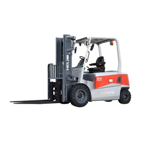
Foreword This manual briefly introduces the technical parameters of our G3 series 4-5 ton lithium battery counterbalanced forklift truck including the structure, working principle and maintenance of the main parts. It can help operators to use this series of forklift trucks reasonably and make the forklift truck play the most effective role. -
Page 3
CONTENTS I. Main specifications of forklift trucks …………….. 1 1. External view of the truck ………………1 2. Main parameters………………….2 3. Size and weight of the main parts that can be disassembled ……..3 II. Construction, Principle, Adjustment and Maintenance of Forklift Trucks ……. 4 1. -
Page 4
I. Main specifications of forklift trucks 1. External view of the truck… -
Page 5
2. Main parameters Item Unit CPD40 CPD45 CPD50 With fork 3990 3990 3990 Overall length Without fork 2920 2920 2920 Front wheel 1350 1350 1500 Overall width Frame 1346 1346 1468 Mast, lowered 2240 2240 2230 Overall height Overhead guard 2275 2275 2270… -
Page 6
3. Size and weight of the main parts that can be disassembled Dimension Model Parts name Unit and weight CPD40 CPD45 CPD50 Max. 1625× 1274× 1511 Overhead dimension guard Weight 132.3 Max. 540×1334×2250 Mast dimension M300 Weight 1015 Max. φ350×1326 dimension Drive axle Weight… -
Page 7
II. Construction, Principle, Adjustment and Maintenance of Forklift Trucks 1. Transmission system 1.1 General description The 5t domestic integrated electrical bridge mainly consists of two reduction box assemblies, a fully enclosed AC motor and a set of brake assemblies. The reduction box assembly contains a planetary reduction mechanism to increase the output torque of the bridge assembly. -
Page 8
1.2.1 Disassembly and assembly of right reduction box assembly Lift and erect the integrated bridge assembly, remove the connection bolts of the reduction box assembly, specification: 14-M12*1.25. When installed, the bolt torque is 124-165N.m. Remove the reduction box assembly and the primary planetary reduction assembly. -
Page 9
Remove the end cover bolt of the reduction box assembly, remove the hub end cover, O-ring seal and hub retainer ring in turn; Then remove the retainer ring, secondary reduction assembly, gear ring cylindrical pin and gear ring from the other side in turn, and the disassembly complete. -
Page 10
friction plate (large), baffle, spacer, friction plate (small), cylinder pin, baffle (spline), compression spring, etc. in turn. 1.2.3 Disassembly of piston assembly Remove the piston bolt, bolt head specification M17, remove the compression spring, then remove the piston. Torque for piston bolt installation is 22-30N.m. -
Page 11
1.2.4 Brake lever, fork disassembly After removing the retainer ring, remove the handle and torsion spring in turn, loosen the bolt, remove the flange and brake fork. 1.3 Announcements in daily maintenance 1)Replace the brake pull lock or adjust the brake structure When the hand brake pull lock is released completely, the wheel is suspended and the wheel hub of the disk-rotating drive axle can make it rotate freely. -
Page 12
2)Fuel quantity of Integrated electrical bridge Model: HELI dedicated 85w/90 Brake side: 1.6-1.7L No brake side: 1-1.1L Every 10-15 days, it is necessary to check the integrated electrical bridge for no oil leakage, if necessary to find out the cause, and timely fill oil. -
Page 13
2. Brake system 2.1 General description The brake system includes service brake and parking brake. Full hydraulic braking mode is adopted for driving brake, and the power source for brake is hydraulic gear pump. The service brake system is mainly composed of brake pedal, brake pump, brake valve and oil-cooled disc brake. -
Page 14
2.1.1 Brake pedal The installation of brake pedal is suspension type. Specific structure is shown in Figure 2-2. The force acting on the pedal is converted to the brake oil pressure by the push rod of the brake valve, and the wet disc brake of the driving axle is acted on to realize braking. 2.1.2 Brake valve The shape of the brake valve and the position of each interface are shown in Fig. -
Page 15
Figure 2-4 (2)The connection of parking brake The parking brake push rod on the driving axle is connected with one end of the brake rod through the brake cable, and the parking brake is realized by changing the working state of the brake push rod. -
Page 16
2) Repeatedly press down the brake pedal, so that the hydraulic pressure can discharge the mixed gas in the brake system. 3) When the air is exhausted and the exhaust plug ejects completely hydraulic oil, press the brake pedal and tighten the gas exhaust plug, and the pre-tightening torque should reach 10N m. -
Page 17
3. Steering system 3.1 General description The steering control mechanism of G3 series 4-5t forklift trucks is mainly composed of steering wheel, pipe column, coupling shaft, steering unit and installation bracket (as shown in Figure 3-1). They are fixed on the panel of instrument bracket by installation bracket. The steering wheel, pipe column and coupling shaft are connected together. -
Page 18
Figure 3-1 Steering operation device 3.1.1 Steering wheel and its function The steering wheel is the most direct component for the driver to control the driving direction of forklift truck. During the normal driving process of forklift truck, the driver turns the steering wheel to the left or right, so that the forklift truck can drive to the left or right. -
Page 19
maintain his body balance. During these operations, the speed of forklift driving and steering should not be too high to avoid accidents There is a horn in the center of the steering wheel. When the driver wants to prompt the pedestrians, he can use his hand to press down the cover of the box marked with horn. -
Page 20
Figure 3-3 Principle diagram of the hydraulic steering system 3.1.4 Full hydraulic steering unit Full hydraulic steering gear (Figure 3-4) transmits pressure hydraulic oil to the steering cylinder according to the rotation angle of steering wheel. The hydraulic oil drives the piston rod of the steering cylinder to move left and right, and realizes steering through the steering mechanism. -
Page 21
steering system will automatically overflow in order to protect the components of the system from damage, so as to realize self-protection. The output pressure of the steering gear has been adjusted according to different models before leaving the factory. The user can not adjust it by himself to avoid damaging the hydraulic components. -
Page 22
is supported by thrust gaskets on the inner side of the steering upper and lower axle plates. The thrust gaskets are also self-lubricating as the axle sleeves. The connection between the main pin and the steering knuckle assembly is achieved by tightening the screw, and the main pin and the steering knuckle assembly are relatively fixed. -
Page 23
1.hub cover 21.washer 16 2.hub 22.support seat of steering axle 3.hub bolt 23.sleeve 4.hub nut 24.shim 5.left steering knuckle 25.end cover 6.link rod 26.sleeve 7.straight through type grease nipple 27.V type seal ring 8.steering cylinder assembly 28.washer 9.steering axle assembly 29.thrust washer 10.baffle 30.main pin… -
Page 24
piston rod is realized by O-ring, and the seal between piston and cylinder inner wall is realized by lattice ring. The cylinder head and cylinder are connected by threads. There are two supporting rings in the cylinder head. The dust-proof seal between the cylinder head and the piston rod adopts the El seal ring. -
Page 25
Figure 3-7 Connection between steering knuckle and axle 3.1.8 Hub The hub is used to connect the steering wheel with the steering knuckle assembly. There are two tapered roller bearings in the hub. The inner ring is mounted on the steering knuckle body, the outer ring is mounted in the hub, and there is grease in the hub. -
Page 26
(5) When the torque is higher than the prescribed value, retreat the round nut close to the end face of the bearing by 1/24-1/12 turn, and then measure the hub’s torque until the hub’s rotational torque reaches the prescribed value. Similarly, when the torque is lower than the prescribed value, retreat the round nut close to the bearing by 1/24-1/12 turn, and then measure the hub’s torque. -
Page 27
3.2.3 Steering system troubleshooting Problem Analyses of trouble Remedies Fail to turn Pump damaged or breaking down. Replace hand-wheel Hose or joint damaged or pipeline blocked. Clean or replace The pressure of the safety valve is too low. Adjust the pressure Air in steering oil circuit. -
Page 28
Note The manufacturer reserves the right to continuous improvement of the product. If there is any discrepancy between the physical object and the instructions, please consult the manufacturer. The principle diagram of the electrical system is shown in Fig. 4-1 and Fig. -
Page 29
Figure 4-1 Principle diagram of electric system(CPD40~50-GB3Li)… -
Page 30
Figure 4-2 Principle diagram of electric system(CPD40~50-GB2Li)… -
Page 31
4.2 Instrument 4.2.1 Jiachen color screen instrument 4.2.1.1 General description (1) It is a color screen instrument connected to the vehicle system by CAN bus. The color screen instrument can display the running state of the vehicle and has diagnostic function. -
Page 32
4.2.1.3 Display interface Fig. 4-4 Instrument interface display information introduction Fig. 4-5 Instrument interface-fault display 4.2.1.4 Functions and applications (1) Hour meter The number shows the cumulative working time of the current truck. The key switch is connected to the power supply. After the truck starts to work, the working timer starts to count. -
Page 33
Display the current battery electric quantity. The current electric quantity is displayed at the top of the battery icon. (4) Travelling mode Display the current working mode, there are «P», «E», «S» three levels. (5) Steering wheel Angle indicator Represents the direction of the steering wheel. (6) Steering angle indicator The arrow represents the direction of the steering wheel. -
Page 34
to the CAN bus network. Its node definition is shown in the following table: CAN bus network related figures Module Traction main CPU2.0: Traction main CPU2.1 Traction controller Pump main CPU5.0: Pump main CPU5.1 Pump controller Independent steering CPU13.0: Independent steering Steering controller CPU13.1 Instrument 16.0: Instrument 16.1… -
Page 35
Fig. 4-8 Instrument interface — fault display 4.2.2.4 Functions and applications (1) Milemeter The number shows the total mileage of the current truck. (2) Battery status Display the current battery power icon, the top of the battery icon shows the current power value. -
Page 36
When parking brake switch is closed, parking brake indicator light is on; Seat belt light, reserved function, this LED light is temporarily not in use. 4.3 Control system 4.3.1 Introduction to Control System This series of balanced weight forklift adopts Swedish INMOTION AC motor controller or Italian ZAPI AC motor controller, controller is a three-phase AC asynchronous motor inverter, which controls traction motor, pump motor and steering motor. -
Page 37
Figure 4-9 Assembly of control device(CPD40~50-GB3Li) Model of traction controller:Inmotion ACS80XL-550C-35P 80V/550A Model of pump controller: Inmotion ACS80L-440C-35P 80V/440A Model of steering controller:Inmotion ACS80S-220C-35P 80V/220A 4.3.3 ZAPI Control system composition Figure 4-10 Assembly of control device(CPD40~50-GB2Li) Model of traction controller: ZAPI ACE3(80V/550A) Model of pump controller: ZAPI ACE3(80V/450A)… -
Page 38
◆ Test the truck with four wheels raised (off the ground) after the controller being fixed, in that case there will be no danger even the connection is in error. ◆ A certain amount of voltage will remain in filter capacitance after the turn off of the electric switch. -
Page 39
4.5.2 Lithium battery usage The usage and routine maintenance of the lithium battery will influent lithium battery life and performance. So the operator should maintain the lithium battery according to the manual and actual conditions. 4.5.3 Lithium battery maintenance (1) Please ensure that specified lithium charging device is used for charging, and the charging current should not exceed 2C;… -
Page 40
4.5.5 Lithium battery error and resolution The cause that made the Lithium battery error is various, except the effect of the quality manufacture and transport storage, mostly due to the improper maintenance. Find out the faults and analyze the causation as soon as possible to exclude. 4.5.6 Daily maintenance (1) Check the wear status on the contact point;… -
Page 41
4.6 Diagnosis 4.6.1 General instruction The traction control system, loading control system, steering control system and color screen instrument system assembled in the truck are continually monitoring micro-processor controller. They all have a diagnosis program to a main function. The program includes the following point: (1) Diagnosis when the key switch being off: the circuit of the watching dog, current censor, charging of the capacity, phase voltage, driving of the connector, CAN-bus connector,… -
Page 42
2)Fault of harness; fault of accelerator signal CAN error Check if the controller and CAN bus has fault. Battery low voltage Charge the battery Pump speed 1 switch active at Reset the tilting switch key on Pump speed 2 switch active at Reset the tilting switch key on Pump speed 3 switch active at… -
Page 43
relay. ) average execution time out of Restart the key. range Short circuit Check the harness of power and motor. The temperature of traction driver is over high and it ACS temp high needs to be cooled down. 1)The temperature of traction motor is over high and it needs to be cooled down;… -
Page 44
1)Over high temperature of motor Motor temp high 2)Fault of motor temperature sensor or harness Check if there is short circuit of pump motor and Over Current Error cable. 1)Change pre-charging resistance. Charging error 2)Low battery voltage 3)Fault of harness 1)Check battery voltage;… -
Page 45
voltage. Check battery parameters. 1)Check battery voltage; DC bus low 2)Check battery voltage; 3)Check if main contactor is connected. 1)Restart the key; Internal supply error 2)Check the load and harness of controller at 5V and 12V port. BMS temperature protection Check the lithium battery temperature BMS temperature high Check the lithium battery temperature… -
Page 46
FAILURE Fault in the hardware section of the logic board which deals with voltage feedbacks of motor phases. Troubleshooting The failure lies in the controller hardware. Replace the controller. Cause This fault is displayed when the controller detects an undervoltage condition at the key input . -
Page 47
Troubleshooting: — Motor internal connections — If motor windings/cables have leakages towards truck frame — If no problem are found on the motors, the problem is inside the controller, it is necessary to replace the logic board. Cause 1 Start-up test. Before switching the LC on, the software checks the power bridge: it turns on alternatively the high-side power MOSFETs and expects the phase voltages increase toward the positive rail value. -
Page 48
replace the LC. Cause The LC coil is driven by the controller, but it seems that the power contacts do not close. In order to detect this condition the controller injects a DC current into the CONTAC motor and checks the voltage on power capacitor. If the power capacitors get discharged it means that the main contactor is open. -
Page 49
Troubleshooting: It is necessary to improve the controller cooling. To realize an adequate cooling in case of finned heat sink important factors are the air flux and the cooling-air temperature. If the thermal dissipation is realized by applying the controller base plate onto the truck frame, the important factors are the thickness of the frame and the planarity and roughness of its surface. -
Page 50
procedure. Troubleshooting: — Check the wirings. Check the mechanical calibration and the functionality of the accelerator potentiometer. Acquire the maximum and minimum potentiometer value through the PROGRAM VACC function. — If the problem is not solved, replace the logic board. Cause: Incorrect starting sequence. -
Page 51
Cause: Lithium battery alarm ; Current cut-out protection . when this alarm appears , the truck should stop to work , inhibit traction and lifting and tilt ,only steering function can work as normal BMS10 Troubleshooting:Check the lithium battery,ask for help to the lithium battery manufacturer Cause:… -
Page 52
manufacturer Cause: Lithium battery alarm ; The cell of battery over-discharge .when this alarm appears , the truck should stop work , inhibit traction and lifting and tilt ,only BMS2 steering function can work as normal Troubleshooting:Check the lithium battery,ask for help to the lithium battery manufacturer Cause:… -
Page 53
Cause: Networking alarm ; the traction inverter received the 1AA message from the networking device,if the inverter lost this message,this alarm will appears, the truck should inhibit lifting and traction function , but tilt , side shift , attachment , 0X1AA TIMEOU steering function can work as norma… -
Page 54
implemented in this truck Cause This alarm occurs only when the controller is configured to drive a PMSM and the feedback sensor selected in the HARDWARE SETTINGS list is ENCODER ABI + PWM. The controller does not detect correct information on PWM input at start-up ACQ. -
Page 55
Troubleshooting: — Check the wirings. — If the motor direction is correct, swap A and B signals. — If the motor direction is not correct, swap two of the motor cables. — If the problem is not solved, contact a Zapi technician Cause: WRONG The inverter key voltage is wrong . -
Page 56
STOP analog, see paragraph 7.2.3). Troubleshooting: — Check the temperature read by the thermal sensor inside the motor through the MOTOR TEMPERATURE reading in the TESTER function. — Check the sensor ohmic value and the sensor wiring. — If the sensor is OK, improve the cooling of the motor. — If the warning is present when the motor is cool, replace the controller. -
Page 57
Troubleshooting — Check if there is a short circuit or a low-impedance conduction path between the negative of the coil and -B. — Collect information about: o the voltage applied across the EVP2 coil, o the current in the coil, o features of the coil. -
Page 58
Cause: The minimum voltage of the lift potentiometer is not correctly set. PUMP VACC Troubleshooting: NOT OK It is suggested to repeat the acquiring procedure of MIN LIFT and MAX LIFT (see paragraph 9.2). Cause: Man-presence switch is not enabled at pump request. Troubleshooting: PUMP — Check wirings. -
Page 59
Troubleshooting: — Verify that the EB coil is connected correctly . — Verify that the parameter POSITIVE E.B.is set in accordance with the actual configuration . The software, in fact, depending on specific parameter value, makes a proper diagnosis; a wrong configuration of this parameter could generate a false fault. -
Page 60
Troubleshooting — Verify the motor phases connection on the motor side — Verify the motor phases connection on the inverter side — Check the motor power cables. — Replace the controller. — If the alarm does not disappear, the problem is in the motor. Replace it. Cause: WRONG Wrong software version on supervisor uC. -
Page 61
Cause: At start-up, the hardware circuit dedicated to enable and disable the MC driver is found to be faulty. The hexadecimal value “XX” facilitates FAULT Zapi technicians debugging the problem Troubleshooting: This type of fault is not related to external components. Replace the logic board. Cause: The CPOT BRAKE input read by the microcontroller is at its maximum value BRAKE… -
Page 62
Troubleshooting: Execute a CLEAR EEPROM procedure (refer to the Console manual). Switch the key off and on to check the result. If the alarm occurs permanently, it is necessary to replace the controller. If the alarm disappears, the previously stored parameters will be replaced by the default parameters. -
Page 63
which has to be replaced. Cause: No load is connected between the NEVP output and the electrovalve positive terminal. COIL Troubleshooting: OPEN — Check the EVP condition. — Check the EVP wiring. — If the problem is not solved, replace the logic board. Cause — The EVP driver is shorted . -
Page 64
Cause The logic board measures a key voltage that is constantly out of range, below the VKEY minimum allowed value. Troubleshooting SHORTE — Check that the battery has the same nominal voltage of the inverter. — Check the battery voltage, if it is out of range replace the battery. — In case the problem is not solved, replace the logic board. -
Page 65
paragraph 9.1). The acquired values MIN VACC and MAX VACC are inconsistent. Troubleshooting: Acquire the maximum and minimum potentiometer values through the PROGRAM VACC function. If the alarm is still present, check the mechanical calibration and the functionality of the accelerator potentiometer. If the problem is not solved, replace the logic board. -
Page 66
SHORTE Troubleshooting — Check that motor phases are correctly connected. — Check that there is no dispersion to ground for every motor phases. — In case the problem is not solved, replace the controller. Cause: One or more on/off valve drivers are shorted. DRV. -
Page 67
Cause: The EVP driver is not able to drive the EVP coil. The device itself or its driving circuit is damaged. DRIVER OPEN Troubleshooting: This fault is not related to external components. Replace the logic board. Cause: This alarm occurs when there is an overload of one or more EV driver. As soon as the overload condition has been removed, the alarm disappears by releasing and then enabling a travel demand. -
Page 68
TION Troubleshooting: The alarm ends when the acquisition is done. Cause: This is a safety related test. It is a self-diagnosis test that checks the communication between master and supervisor microcontrollers. NO CAN MSG. Troubleshooting: This alarm could be caused by a CAN bus malfunctioning, which blinds master- supervisor communication Cause: CHECK… -
Page 69
Troubleshooting: — Check if there is a short or a low impedance path between the negative coil terminal and -BATT. — Check if the voltage applied is in accordance with the parameters set . — If the problem is not solved, replace the controller. Table 4-5 Fault list of auxiliary pump, auxiliary traction ACE3 traction slave alarms (node 2.1)and ACE3 pump slave alarms (node ALARM… -
Page 70
Cause: The voltage read by the microcontroller at the steering-sensor input is not within the STEER RIGHT VOLT ÷ STEER LEFT VOLT range, programmed through STEER the STEER ACQUIRING function . SENSOR Troubleshooting: Acquire the maximum and minimum values coming from the steering potentiometer through the STEER ACQUIRING function. -
Page 71
Cause: The algorithm implemented to check the main RAM registers finds wrong WRONG contents: the register is “dirty”. This alarm inhibits the machine operations. Troubleshooting MEM. Try to switch the key off and then on again, if the alarm is still present replace the logic board. -
Page 72
Cause: This alarm occurs when the A/D conversion of the analog inputs returns frozen values, on all the converted signals, for more than 400 ms. The goal of this ANALOG diagnosis is to detect a failure in the A/D converter or a problem in the code flow INPUT that skips the refresh of the analog signal conversion. -
Page 73
Table 4-6 Fault list of steering pump main CPU ACE0 independent steering pump master alarms (node 13.0) CODE ALARM NAME Cause: This is a safety related test. It is a self-diagnosis test that involves the logic between master and supervisor microcontrollers WATCHDOG Troubleshooting: This alarm could be caused by a CAN bus malfunctioning, which blinds… -
Page 74
the motor voltage feedback tested; if it is lower than expected value (a range of values is considered), the controller enters in fault state. Troubleshooting — If the problem occurs at start up (the LC does not close at all), check: o motor internal connections (ohmic continuity);… -
Page 75
power capacitors get discharged it means that the main contactor is open. Troubleshooting — LC contacts are not working. Replace the LC. — If LC contacts are working correctly, contact a Zapi technician. Cause In standby, the sensor detects a current value different from zero. STBY I HIGH Troubleshooting The current sensor or the current feedback circuit is damaged. -
Page 76
Troubleshooting: Check the temperature read by the thermal sensor inside the motor through the MOTOR TEMPERATURE reading in the TESTER function. — Check the sensor ohmic value and the sensor wiring. — If the sensor is OK, improve the cooling of the motor. — If the warning is present when the motor is cool, replace the controller. -
Page 77
Troubleshooting: — Check wirings. — Check microswitches for failures. — Through the TESTER function, check the state of the inputs are coherent with microswitches states. — If the problem is not solved, replace the logic board. Cause: This alarm occurs when both the travel requests (FW and BW) are active at the same time. -
Page 78
Cause: Controller is acquiring data from the absolute feedback sensor. ACQUIRING A.S. Troubleshooting: The alarm ends when the acquisition is done. Cause This alarm occurs if the absolute position sensor is used also for speed estimation. If signaled, it means that the controller measured that the engine was moving too quick. -
Page 79
Cause The motor current has overcome the limit fixed by hardware. Troubleshooting OVERLOAD Reset the alarm by switching key off and on again. If the alarm condition occurs again, ask for assistance to a Zapi technician. The fault condition could be affected by wrong adjustments of motor parameters. Cause: Mismatch between “ENCODER PULSES 1”… -
Page 80
Troubleshooting: — Check that LIFT and LOWER requests are not active at the same time. — Check the LIFT and LOWER input states through the TESTER function. — Check the wirings. — Check if there are failures in the microswitches. — If the problem is not solved, replace the logic board. -
Page 81
Troubleshooting: If the EVP TYPE parameter is set to ANALOG (See paragraph 8.1.1), please acquire again the values of MIN LOWER and MAX LOWER. If the controller is in configuration COMBI and lifting is proportional, please acquire again also the values of MIN LIFT and MAX LIFT. Cause: There is a hardware problem in the smart driver circuit . -
Page 82
Cause Short circuit between two motor phases. The number that follows the alarm identifies where the short circuit is located: — 36 à U – V short circuit — 37 à U – W short circuit — 38 à V – W short circuit MOT.PHASE SH. -
Page 83
capacitors: — High voltage à Overvoltage condition — Low/normal voltage à Undervoltage condition Troubleshooting If the alarm happens during the brake release, check the line contactor contact and the battery power-cable connection. Cause: At start-up, the hardware circuit dedicated to enable and disable the MC driver is found to be faulty. -
Page 84
Troubleshooting — Check the motor power cables. — Check the impedance between U, V and W terminals and -Batt terminal of the controller. — Check the motor leakage to truck frame. — If the motor connections are OK and there are no external low impedance paths, the problem is inside the controller. -
Page 85
motor parameters. Cause The voltage feedback of LC driver (A16) is different from expected, i.e. it is not in accordance with the driver operation. Troubleshooting — Verify LC coil is properly connected. POSITIVE LC — Verify CONF. POSITIVE LC parameter is set in accordance with the OPEN actual coil positive supply (see paragraph 7.2.5). -
Page 86
OUT function is active (POSITIVE EB = 1 or 2). Troubleshooting: Check connector B1: it must be connected to the battery voltage (after the main contactor). Cause: The output of the motor thermal sensor is out of range. Troubleshooting: SENS MOT — Check if the resistance of the sensor is what expected measuring its TEMP KO resistance. -
Page 87
— In case no failures/problems have been found, the problem is in the controller, which has to be replaced. Cause This alarm occurs when an overload of the MC driver occurs. Troubleshooting — Check the connections between the controller outputs and the loads. COIL SHOR. -
Page 88
Cause This fault appears when no load is connected between the NLC output and the positive voltage (for example +KEY). Troubleshooting LC COIL OPEN — Check the wiring, in order to verify if LC coil is connected to the right connector pin and if it is not interrupted. -
Page 89
Troubleshooting If the problem occurs permanently it is necessary to replace the logic board. Cause: At start-up, the hardware circuit dedicated to enable and disable the EV drivers is found to be faulty. The hexadecimal value “XX” facilitates Zapi technicians debugging the problem. HW FAULT EV. -
Page 90
Cause: Warning on supervisor uC. WARNING SLAVE Troubleshooting: Connect the Console to the supervisor uC and check which alarm is present. Cause The error between the Iq (q-axis current) setpoint and the estimated Iq is out of range. MISMATCHED Troubleshooting Ask for assistance to a Zapi technician in order to do the correct adjustment of the motor parameters. -
Page 91
according to the value read by the voltmeter. — Replace the battery. Cause: At start-up the amplifiers used to measure the motor voltage sense voltages above 3 V or below 2 V. WRONG ZERO Troubleshooting: This type of fault is not related to external components. Replace the logic board. -
Page 92
Troubleshooting: Acquire the maximum and minimum values from the steering potentiometer through the STEER ACQUIRING function. Check the mechanical calibration and the functionality of the potentiometer. — If the problem is not solved, replace the logic board. Cause Mismatch between “ENCODER PULSES 1” parameter and “ENCODER WRONG ENC PULSES 2”… -
Page 93
Troubleshooting Try to switch the key off and then on again, if the alarm is still present replace the logic board. Cause: Supervisor microcontroller has detected that the master microcontroller has imposed a wrong setpoint for TG or EB output W.SET. -
Page 94
code flow that skips the refresh of the analog signal conversion. Troubleshooting If the problem occurs permanently it is necessary to replace the logic board. Cause: The software is not compatible with the hardware. Each controller produced is “signed” at the end of line test with a specific code mark saved in EEPROM according to the customized Part Number. -
Page 95
5. Hydraulic system The truck adopts load-sensitive hydraulic system (as shown in the figure), which mainly consists of working oil pump, multi-way valve, lifting cylinder, tilting cylinder and pipeline. The working oil pump is driven by motor, and the hydraulic oil is distributed to working cylinder by multi-way valve through gear oil pump. -
Page 96
The multi-way valve is a piecewise multi-way valve. The hydraulic oil from the working oil pump is controlled by a multi-way valve lever, which distributes the high pressure oil to the lifting or tilting cylinder and returns the oil to the tank. The shape of the multi-way valve is shown in the following figure. -
Page 97
Figure 5-3 Oil inlet piece of multi-way control valve Figure 5-4 Lifting and lowering piece of multi-way control valve Figure 5-5 Tilting piece of multi-way control valve Figure 5-6 Auxiliary piece of multi-way control valve… -
Page 98
Figure 5-7 Stroke switch built at the end of the covers of tilting piece and auxiliary piece 6. Lifting system Table 6-1 Main parameters Item Content Mast type Rolling type, weld mast with free lift, two-stage telescopic type Cross section of inner mast Cross section of outer mast Max. -
Page 99
6.1 General description The lifting system is of the two-stage roller type with vertical up and down. It consists of the inner mast, the outer mast, two rear lifting cylinder, fork carrier, backrest and fork. 6.2 Inner and outer mast The inner and outer portal frames are welded parts, and the whole mast is mounted on the frame by supporting axle. -
Page 100
through the tilting cylinder. Under the action of the tilting cylinder, it can tilt forward and backward, with a forward tilt of 6 degrees and a backward tilt of 8 degrees. The channel of outer mast is C type, and one pair of rollers is installed in its upper end; the channel of inner mast is H type, and its lower part is installed with a pair of rollers. -
Page 101
Readjust the stroke of the lift cylinder when the lift cylinder, the inner mast or the outer mast is replaced. As following: (1) Place piston rod heads into the upper beam of the inner mast without shims. (2) Slowly lift the mast to the maximum stroke of the cylinder, check whether the two cylinders are synchronized. -
Page 102
(3) Lift the fork to the highest point and confirm that the clearance B between the fork carrier’s limit block and the inner mast’s limit block is 5-10 mm. (4) Make the fork carrier fall to the ground and tilt back in place, adjust the adjusting nut of the upper end joint of the chain, so that the tension of the two chains is the same. -
Page 103
(4) Take apart bolts which fastened lift cylinders and the inner mast. Hang up the inner mast without losing shims of the piston rod heads carefully. (5) Take apart bolts which jointed lift cylinders and the bottom of outer mast and take apart the oil-pipe between two lift cylinders without loosing the nipple. -
Page 104
III. Lithium battery changing 1. General description Lithium battery is the energy source of the truck. When the working intensity is high and the operation duration is long, the lithium battery needs to be replaced. The lithium battery can be changed from the right side of the truck body by forklift, electric pallet truck, pallet stacker and other tools. -
Page 105
H3 series 2.5 t electric forklift truck can be picked up by another H3 series 2.5 t electric forklift truck. It is known that the fork length L4 of the 2.5 t electric forklift truck of Heli H3 series is 1070 mm. The front overhang L2 of the truck is 465 mm, the fork feed L9 is about 720 mm, and the lithium battery weight Q1 of 80V/600Ah is 1185 kg. -
Page 106
(2)Disconnect the lithium battery connections. (3)Loose and remove the lithium battery limit block. (4)Pick up the lithium battery with forklift truck, electric pallet truck or pallet stacker. -
Page 107
(5)Remove the lithium battery from the compartment and place the lithium battery on pre-prepared carrier. Please reserve enough space for fork in and out. (6)Use the crane to separate the lithium battery pack from the bottom counterweight 4. Steps to install the lithium battery Please install the lithium battery according to following steps: (1)Install the lithium battery pack together with the auxiliary counterweight by crane. -
Page 108
(2)Transport the lithium battery pack to the battery warehouse by pallet truck or forklift truck. (3) Put down the lithium battery until the right side of lithium battery coincide with the inner side of lithium battery limit block. (4)Put down lithium battery limit block and adjust the limit screw to the end face of the lithium battery box. -
Page 109
(5)Connect the battery. (6)Close the side door.
-
Contents
Table of Contents -
Bookmarks
Quick Links
Related Manuals for HELI CPD15
Summary of Contents for HELI CPD15
-
Page 2
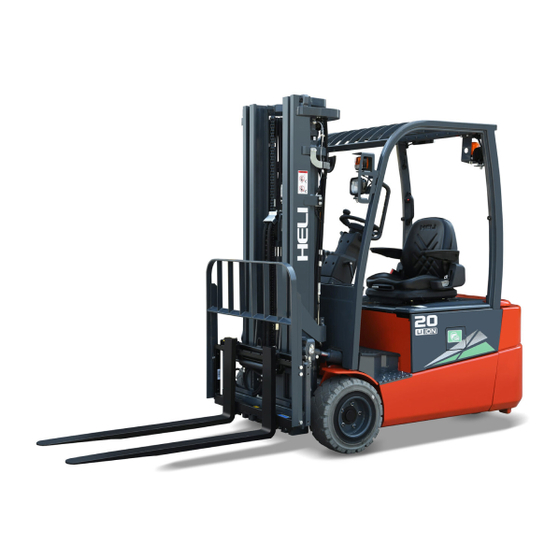
FOREWORD AC type three wheel lithium battery powered forklift truck with front drive is designed on the base of advantages of some trucks made by domestic and foreign manufacturers and developed in introduced technology from abroad to meet the market needs. These trucks are all suited for handling and stacking packed goods in stations, ports, goods yards, warehouses, food processing factory, light and textile industries and other factories. -
Page 3: Table Of Contents
CONTENTS I. Safety Rules for Opeartion and Daily Maintenance of Forklift Truck ……. 2 II. Main Specifications of Forklift Truck …………… 7 III. Construction, Priciple, Adjustment and Maintenance of Forklift Truck ….10 1. Transmission System ………………10 2. Brake System ………………..16 3.
-
Page 4: Safety Rules For Opeartion And Daily Maintenance Of Forklift Truck
Ι. Safety Rules for Operation and Daily Maintenance of Forklift Truck It is important that driver and manager for forklift trucks remember the principle of the “first safety” and ensure the safety operation as the description in 《OPERATION AND SERVICE MANUAL》&《OPERATION MANUAL》. 1.
-
Page 5
(7) Make trying operation of the mast for lifting, lowing and Fwd/Bwd tilting and the truck for steering and braking. 4. Operation of Forklift Truck (1) Only trained and authorized operator shall be permitted to operate the truck. (2) Wear all the safety guards, such as shoes, helmet, clothing and gloves while operating the truck. -
Page 6
necessary. (13) Tilt the mast of the high lift forklift truck as backward as possible while the truck working. Use minimum forward tilt angle and Min. reverse tilt when loading and unloading. (14) Be careful and slowly driving over a dockboard or bridge-plate. (15) Shut down the truck and don’t stay on the truck when checking battery or fuel lever. -
Page 7
b) Check piping, joints, pumps and valves for leaks or damages; c) Check parking brake. The unladen truck can park on the 15% grade ramp, when the parking lever is pulled to the bottom; d) Check instruments, lighting, switches and wiring to see if they work normally or not. -
Page 8
(3)Lubrication chart Note: for the truck without brake liquid, it is not necessary to refer to the chart for relative operation. -
Page 9: Main Specifications Of Forklift Truck
Ⅱ. Main Specifications of Forklift Truck Enternal view of forklift trucks…
-
Page 10
Main specifications Model CPD15 CPD16 CPD18 CPD20 Unit Configuration No. SQ-GB2Li Rated capacity 1500 1600 1800 2000 Load center Power Lithium battery Driving mode Sit-on type Lifting height 3300 Free lift Mast tilting angle (front deg. /rear) Fork size 35× 100× 920 40×… -
Page 11
Dimensions and weight of main dismountable parts CPD15SQ CPD16SQ CPD18SQ CPD20SQ model Unit GB2Li item 410× 1060× 775 425× 1060× 775 455× 1060× 775 Max. overall size Counterweight Weight 1068 980× 190× 522 980× 190× 522 980× 190× 630 980× 190× 630 Assistant Max. -
Page 12: Transmission System
Ⅲ. Construction, Principle, Adjustment and Maintenance of Forklift Trucks 1. Transmission system 1.1 General description The transmission system of the three wheeled forklift truck includes transmission system we call traditionally and brake system. Front wheel dual driving motor structure makes the right and left wheel of three wheeled truck has drive axle, redactor, brake and driving motor independently to improve working efficiency.
-
Page 13
maintenance. 1.2.1 Removal of the wheels Drain off the gear oil inside of the transmission box before disassembling. Loose 6 drive nut and remove drive wheel. Then loose the 7 bolts on frame hexagon socket bolts and remove transmission box connected with travelling motor from frame. Refer to figure 1-1. -
Page 14
1.2.3 Disassembling and assembling of transmission box It is not necessary to disassemble this part normally. If has to, please contact HELI sales company. 1.3 Assembling of transmission system 1.3.1 Assembling of travelling motor… -
Page 15
(3) Screw a new stopping nut (part 4) on and tighten with socket wrench. Tightening torque:55 Nm(M20 × 1,taper φ 25);68 Nm(M14 × 1.5,taper φ 20) (4) Coat O-ring (part 5) slightly with transmission fluid and push it onto centering seat of motor. -
Page 16
The axle is applicable to solid tyre. (1) Clean mating surfaces on wheel shaft and wheel thoroughly and check if it is damaged. (2)The bore pattern in the rim should be in line with the bolts of the wheel shaft; then push the wheel on. -
Page 17
DONAXTM or ATFDEXRONⅡ D-21666 or DONAXTG PLUSD-22543 or DONAXTG D-21126;ESSO TYPESUFFIXA or ATF D-21065 or ATF D-21611 or ATF D-22079. (6)Screw fluid filling plug (part 1) with the sealing ring (part 2).Tightening torque: 22Nm. Refer to figure 1-5. Figure 1-5… -
Page 18: Brake System
2. Brake system 2.1 General description Brake system is made up of service brake and parking brake. 2.1.1Serivce brake The service brake is made up of accelerating pedal, brake pedal, traction controller and traction motor. See the figure below for the service brake principle diagram and the structure of brake pedal.
-
Page 19
Note: It is suggest for driver to getting familiar with the brake effect and functioning without load. 2.1.2 Parking brake Electromagnetic parking brake which is installed on traction motor shaft is applied on three wheeled truck. 1) Automatic parking brake When truck is braked or is stopped, electromagnetic parking brake is applied to lock traction motor output shaft. -
Page 20
Danger: Except under emergency case, it is prohibited to start electromagnetic parking brake through power-off parking brake. When electromagnetic parking brake is applied, do not tow the truck. -
Page 21: Steering System
3. Steering system 3.1 General Description The function of steering system of forklift is to change the driving direction of the forklift or keep the forklift in straight line driving. The performance of steering system directly concerns with the driving safety, operation efficiency of forklifts and labor intensity of drivers.
-
Page 22
hand, the controller provides electrical signal to steering motor to control steer wheels to rotate according to steering wheel operation. It can ensure light and flexible steering at low speed and stable and reliable steering at high speed. 3.3 Composition of Steering System (1) Control mechanism of steering Figure 3-1 Steering unit The steering control mechanism of the truck is mainly composed of steering wheel,… -
Page 23
details). (3) Steering transmission mechanism The steering motor drives meshing gears and then is transmitted to steer wheel. The steering way is simple, easy and convenient. (Refer to the chapter relating to steering axle for more information). 3.4 Integrated electric steering axle The steering rear axle assembly (as shown in Figure 3-2) is composed of steering motor, mechanical structure (including reductor), steering wheel axle and steer wheels and other parts. -
Page 24
Figure 3-2 Electric steering axle (1) Steering motor (2) controller (3) redactor (4) hub assembly 3.5 Adjustment and Maintenance 3.5.1 Rear wheel bearig pre-load adjustment (1) As shown in Fig. 3-3, fill up the chamber formed by wheel hubs, wheel hub bearings and wheel hub covers with lubricating grease. -
Page 25
manually the hub for 3-4turns to ensure its smooth rotation with a specified torque of 2.94-7.8Nm (0.3-0.8kgm). (7) If the torque value necessary to rotate the hub is more than the specified one above-mentioned, screw out the castle nut for 1/6 turn and measure the torque value then. (8) When the torque value measured is up to the specified one, lock the castle nut with a cotter pin. -
Page 26
3.5.3 Steering system troubleshooting Table 3-2 Fault Reasons Remedy No working of steering Check the harness or replace motor No steering No working of steering Check the harness or replace controller Large clearance between Adjust Large noise gears when steering Over wear of gear Replace Make the steering wheel to… -
Page 27: Electric System
4. Electric system 4.1 General description The standard configuration of the electric system include of two controllers. It can succeed in operating the forklift low-noisily, efficiently, smoothly and safety. The electric system is composed of instrument, traction control system, lifting control system, EPS electric steering control system, lithium battery pack, control switch, lighting and wiring harness etc.
-
Page 28
μ ?? ú · ?é è Figure 4-1 Electric system principle diagram(CPD15SQ~20SQ -GB2Li)… -
Page 29
The display implements an interface to the operator through a main page and a number of submenus. a) Turn on the key switch. When the instrument gets power “HELI AC SYSTEM” is displayed on the LED screen. After system self-testing, battery capacity, truck… -
Page 30
Fig. 4-3 Display of the ZAPI instrument when power on (fault-free) b) Battery capacity display: There are 20 grids on the battery capacity indicator. After the truck is powered, the indicator is fully lit (20 grids) if the battery is fully charged. -
Page 31
4.3 Controller 4.3.1 General description The truck adopts the ZAPI ACE2 motor controller imported from Italy, so it has advantages of advanced technology of high frequency MOS tube, superior speed regulating performance, good safety, flexibility and first-class protection etc. The controller assembly includes motor controller, contactor, relay set, fuse ,OPS warning buzzer and the related harness. -
Page 32
; Figure 4-5 CPD15SQ-GB2Li control device assembly… -
Page 33
; Figure 4-6 CPD16SQ-GB2Li control device assembly… -
Page 34
; Figure 4-7 CPD18~20SQ-GB2Li control device assembly… -
Page 35
] 4.4 Motor 4.4.1 Specifications of motors Table 4-2 Specifications of motors Model CPD15~16SQ-GB2Li CPD18~20SQ- GB2Li Item Model of traction motor JXQ-5.4-HL Rated power 5.4kW… -
Page 36
For any questions, please contact the engineers and after sales service of HELI. 1) Battery safety notes (1) Keep the battery away from dangerous goods or environment, such as conductive dust particles, corrosive chemicals, inflammable and explosive materials, dangerous mechanical equipment, high temperature environment, etc;… -
Page 37
(3) Unreasonable use of this series of products may lead to the bulging of the battery unit, and in serious cases, it may lead to the rupture or crack of the plastic shell. At this time, the battery shall be stopped immediately. Please contact the relevant technical department or after-sales service department of our company in time to obtain the treatment method;… -
Page 38
(10) Before using this product, please read the product manual carefully. Children and other untrained personnel are not allowed to use this series of products; (11) It is forbidden to use this series of products in series or parallel with other types of batteries, which may cause personal injury or property loss;… -
Page 39
(5) The self discharge of lithium battery is affected by the ambient temperature and humidity. High temperature and humidity will accelerate the self discharge of lithium battery. It is recommended to store the battery in a dry environment of — 10 ℃ ~ 45 ℃; (6) Non professionals are not allowed to touch, move or disassemble the battery pack and the corresponding high-voltage cable, or other components with high-voltage warning signs;… -
Page 40
(2) The battery shall be charged immediately after use, and shall be fully charged, but overcharge is strictly prohibited; (3) When the truck needs to be stored for a long time, 40% — 60% of the electricity should be kept, please do not fully charge; please fully charge the battery before use; (4) Please check the lithium battery charging socket regularly to ensure that the bracket is not loose, the cover plate of the socket is well sealed, the internal terminal of the socket is not rusted and free of dust, rain and other foreign matters;… -
Page 41
will not be in good contact, resulting in heat or even fire; (4) Do not modify or dismantle the charging port and charging equipment, which may lead to charging failure and fire; (5) In order to avoid serious personal injury, the following precautions should be taken when the truck is charging: a) Do not touch the charging port or the metal terminal in the charging gun;… -
Page 42
4.6 Daily Maintenance (1) Check the wear condition of the contactor. Change it if necessary. Check the contactor every three months. (2) Check the pedals or manual inching switch; measure the voltage drop between the inching switch ends; there is no resistance when the inching switch is closed; there is ringing sound when release. -
Page 43
The manufacturer shall provide quality assurance for the motor controller, and timely inform the manufacturer to provide after-sales service in case of failure; if not authorized and approved by the manufacturer, please do not open the motor controller for maintenance, and the user shall bear the responsibility for personal and property losses caused by the user’s unauthorized maintenance. -
Page 44
Parking brake can be applied only when the truck can not be stopped through braking pedal during travelling. 4.8 Emergency button The emergency power-off switch has the ability to cut off the load current and overload current, which can be used as a safety switch. The emergency power-off switch of the truck has two functions: first, as a safety switch, press the switch in case of emergency to disconnect the battery output, so as to ensure the safety of the whole truck;… -
Page 45
Figure 4-9 Emergency button Danger: Do not press emergency button when travelling. Under certain cases, if emergency button is pressed suddenly, goods may falling down which may cause personnel injury and goods damage. Emergency button can be applied only when the truck can not be stopped with other methods during travelling. -
Page 46
LOGIC Logic card Current protection function failure of logic card: change FAILURE #3 failure 3 the controller. LOGIC Logic card Circuit failure of phase voltage feedback hardware on FAILURE #2 failure 2 logic card. Change the controller. The failure produced when the function of low or over voltage acts. -
Page 47
current micro-control system exceeds the scope allowed for non-operation current. The trouble has nothing to do with the peripheral parts, so the controller needs to be changed. When the electric lock is switch on, inverter will charge the capacitance through power resistance and check if capacitance is fully charged within the time stipulated, otherwise, the capacitance voltage remains 20% lower than battery voltage, the inverter will give alarm and the… -
Page 48
value of parameter “ADJUST BATTERY” of controller is consistent with battery voltage. When electric lock is close, the microprocessor will detect if driver of main contactor is short-circuited and alarm DRIVER Short circuit will be given if yes. Check if there is short circuit on the SHORTED of driver positive pair A 16 of main contactor coil or negative pole. -
Page 49
NODE node signal signal that the other controller can not make normal communication and the controller always is always in the waiting state until CAN communication network is completely normal. Check why the wiring of the modules that fails to communicate is abnormal and see if the software edition or parameter setting is correct. -
Page 50
At start-up stage, if controller detects that there is low logic level signal when key switch is off, there is a fault. Fault analysis: Most possibly is that the voltage is excessively low, suggest to check the followings : (1) If the key switch is based on external load (e.g. the starting of DC-DC converter, the input signal of relay or contactor switch is lower than starting voltage). -
Page 51
OUTPUT safety output Fault analysis: Check if there is short circuit or Low impedance push-pull output betweenA19 and -BATT. If it is the circuit trouble of driver of logic card, change the controller. Before driving the coil of main contactor, controller tests MOS driver or the auxiliary output drive is the invalid HARDWARE Hardware… -
Page 52
The fault has nothing to do with external parts and change the controller. During startup, the controller tests if the voltage of battery is within the nominal scope. Check if the value of WRONG SET Wrong set of BATTERY VOLTAGE parameter in the menu conforms BATTERY battery to that on the voltmeter. -
Page 53
(2) Common fault of pump control system (The second line of instrument indicates “ON NODE 5”) Table 4-6 Common fault of pump control system Fault Implication Note Measures Code The fault is in the internal memory for storing and regulating parameters. When the fault appears, the machine automatically stops. -
Page 54
the ground and circuit break of motor coil. (2) Change the controller The signal output by current sensor detected by High standby micro-control system exceeds the scope allowed for STBY I HIGH current non-operation current. The trouble has nothing to do with the peripheral parts, so the controller needs to be changed. -
Page 55
positive pair A 16 of main contactor coil or negative pole. Change the controller if everything is OK. Detection time : Standby state The alarm indicates the voltage of accelerator is 1V larger than the min. value set in the signal scope (PROGRAM VACC)of accelerator. -
Page 56
INPUT fault contactor, meanwhile the electromagnetic brake or auxiliary output coil is driven. Check if the port of A11 is correctly connected. Change the controller if other parts are correct. At start-up stage, if controller detects that there is low logic level signal when key switch is off, there is a fault. -
Page 57
CHECKSUM Memory fault in flash memory and the fault signal is produced in case of negative value. Fault analysis: The problem is on flash memory of microcontroller. The flash memory may be damaged or the program stored destroyed. Try to reset the program of logic card. -
Page 58
4.9.2 HP-CAN controller This series of controllers can obtain diagnostic information through the times of LED flashes and fault codes sent to the instrument. (1) Common fault of control system (The second line of instrument indicates “ON NODE 5”) Table 4-7 Common fault and remedy of control system CODE NOTE Fault explanation… -
Page 59
● Request microswitch stuck. c) < STANDBY HIGH CURRENT > Test carried out in standby, checks that the current is nil. If this is not verified, an alarm is signalled. This alarm shuts down the machine. Possible causes: ● Current sensor broken and logic failure. First replace the logic, and if the defect persists, replace the power unit. -
Page 60
g) < DRIVER SHORTED > Cause: The driver of the main contactor coil is shorted. Troubleshooting: ● Check if there is a short or a low impedance pull-down between NMC and –BATT. ● The driver circuit is damaged in the controller, which has to be replaced. h) <… -
Page 61
i) < DRIVER SHORTED > Cause: The driver of the main contactor coil is shorted. Troubleshooting: ● Check if there is a short or a low impedance pull-down between NMC (CNA#26) and –BATT. ● The driver circuit is damaged in the controller, which has to be replaced. j) <… -
Page 62
FAILURE #2 failure 2 instrument if it has nothing to do with external components. Drive coil short circuit: Test if there is short circuit COIL SHORT Coil short on the device connecting with output port of the instrument, otherwise, change the instrument. Instrument no longer receives the data from CAN BUS data wire. -
Page 63: Hydraulic System
5 Hydraulic System 5.1 General Description The hydraulic system consists of oil pump, control valve, priority valve, lift cylinder, tilt cylinder, high & low pressure oil pipe an joint etc.The pump is driven directly by the electromotor. The hydraulic oil flow to control valve through the pump and are distribute to cylinders by the control valve.
-
Page 64
cavity, 2 is oil pressing cavity and they are separated by meshing point of two gears. With constant rotation of gear, the suction and discharge outlets of the pump continuously absorb and drain oil. Oil pump is to turn the mechanical energy of motor into hydraulic energy, so the oil pump is the actuating unit of hydraulic system of the forklift. -
Page 65
5.1.2 Control Valve The external of the control valve as shown in Fig. 5-3. Tilting sliding valve lifting sliding valve Main safety valve Figure 5-3 Control valve The control valve adopts two pieces and four body type. The hydraulic oil from working pump distributes the high-pressure oil to the lifting cylinder or tilting cylinder through the control of valve stem. -
Page 66
(1) Spool operation (take the tilt spool valve for example) a) Neutral position (See Fig. 5-4) The high-pressure oil from lift pump returns to the oil tank through the mid-passage. Fig. 5-4 Neutral position b) Pushing-in of spool (See Fig. 5-5) In this time, the spool is pushed in to close the mid-passage. -
Page 67
(2) Motion of safety relief valve The relief valve is mounted between “HP” nozzle of oil pump and “LP” passage. Oil passing through lifting valve C acts on different areas of diameters “A” and “B”, thus, “K” of check valve and “D” of overflow lift valve are on the valve seat as shown in Fig. 5-7. When the pressure regulated in “HP”… -
Page 68
(3) Action of tilt-lock valve Tilt spool valve housing contains a tilt-lock valve. The tilt lock valve is intended to prevent vibrations of the mast resulting from the negative pressure in the tilt cylinder and also to avoid danger incurred from mishandling of the spool. When the lift motor isn’t running, the mast doesn’t be tilted forward by push the tilt lever. -
Page 69
together with a shaft and the shaft is assembled on the valve joint plate with the bracket. The valve levers operate the control valve with the joints. (See Fig. 5-13) Figure 5-13 Control valve As you see in Fig. 5-14, the mast lift up when you push the lift lever forward, the mast fall down when you pull the lift lever backward. -
Page 70
(5) Setting pressure of the control valve (See Fig. 5-15) The pressure of the safety valve shall not be adjusted by non-professional personnel. The adjustment shall follow following procedures: a) Screw off the plug of the measuring hole on the inlet of the control valve. Install an oil pressure gauge capable of measuring 25MPa. -
Page 71
When the hoist valve of control valve is placed at lifting position, hydraulic oil enters into the lower part of piston of hydraulic cylinder from pressure-gradient control valve to selector valve to push rising of piston and lifting of the goods. When the hoist valve of control valve is placed at descending position, the piston rod drops with the action of goods, mast, fork bracket and piston itself, the hydraulic oil is pressed back to oil tank. -
Page 72
5.1.4 Cut-off valve The cut-off valve is mounted at the bottom of the cylinder (See Fig. 5-17) to prevent the goods from falling suddenly when the high pressure pipe is broken. The oil from hoist cylinder passes through the hole A on the outer circumference of the spool when returning to oil tank, if flow rate of oil through the hole is less than the setting value of the valve and the pressure difference before and after spool smaller than spring force, the spool will not move at this time and slide valve does not work. -
Page 73
the lift cylinder without any regulation. When the lift spool is placed in the “down” position, the oil pusses the orifice plate and a pressure difference generates between the chambers A and B, the pressure difference overcomes the force of the spring and moves the valve core right, thus the oil flow being decreased by narrowing of the hole D and C, and reduces the oil flow passing through the orifice plate. -
Page 74
difference between the dip angles. (See Fig. 5-19) When the tilt lever is pushed forward, the high-pressure oil enters into the cylinder body from the cylinder tail, moving the piston forward and causing the mast assembly to tilt forward until 6 degrees. When the tilt lever is pulled backward, high-pressure oil enters into the cylinder body from the guide sleeve and moves the piston backward, tilting the mast assembly backward. -
Page 75
Fig. 5-20 Hydraulic system principle diagram (1) Oil tank (2) Oil suction filter (3) Pump motor (4) Gear pump (5) Control valve (6) Flow regulator valve (7) Cut-off valve (8) Lift cylinder (11) Tilt cylinder Return oil filter (12) -
Page 76
Figure 5-21 Hydraulic pipeline 5.2 Maintenance,Fault Analysis and Remedies 5.2.1 Maintenance Check if there is any seepage and serious oil leakage on the pipe fittings of hydraulic drive system, hoist cylinder, tilt cylinder, oil pump, before and after each shift. Check if the working oil inside work oil tank is sufficient and check and clean the strainer mesh of oil filter mounted in the work oil tank once every week. -
Page 77
Before disassembling the pump, put the removed parts on the paper or cloth. Don’t damage the parts. (See Fig. 5-23) a) Hold the pump cleaned in a vice by lightly clamping the flange section. b) Remove bolts 11, pump cover 5, pump body 1. c) Remove lining plate 6, drive gear2, driven gear 3. -
Page 78
(2) Inspection Check the disassembled parts and wash them with light oil. Don’t wash the rubber items with light oil. a) Body inspection (See Fig. 5-23) If the contact length between pump body lumen and gear longer than 1/2 long of the perimeter, replace the pump body. -
Page 79
e) Replace seal rings, bushings, seal rings, rings, oil seals and snap rings as required. Fig. 5-27 (3) Reassembly a) Fixed the front cover on the clamping. (See Fig. 5-28) Fig. 5-28 b) Install a new seal ring on the front cover of the pump. -
Page 80
f) Install the drive gearon the pump body with the side of the spline downward. Fig. 5-33 g) Install the driven gear on the pump body as the direction shown in Fig. 5-34. Fig. 5-34 Install the lining plate on the side of the gear, don’t confuse the inlet oil port and the outlet oil port. -
Page 81
k) Tighten up the connecting bolts with a specified torque of 9 to 10kg.m after all. Fig. 5-38 l) Take down the pump from the clamping. Apply lubricating grease on the outside circle and lip of the oil seal, install it on the front cover with mould. -
Page 82
~ c) Increase the pump speed to 1500 2000rpm for 10 minutes. ~ d) Make the pump running at a speed of 1500 2000rpm for 5 minutes and increase the pressure to 210kg/ cm by 20~30kg/cm each time. Then make each oil circuit works for 5 minutes and then change the oil filter. -
Page 83
5.2.3 Troubleshooting Trouble Cause Trouble shooting 1) Excessive wearing between the oil 1) Replace the wearable parts or oil pump gear pump body pump. wider-than-normal gap. 2) Wearing and wider-than-normal gap of 2) Replace with new piston sealing ring. the piston sealing part in the lifting cylinder, excessive inner leakage. -
Page 84: Lifting System
6. Lifting system 6.1 Normal type lifting system general description Normal type lifting system is of two stage roller type with veritical up and down moving. It is made up of inner mast, outer mast, two rear lifting cylinder and fork brakcet.
-
Page 85
6.3 Fork bracket The fork bracket runs inside of the iner mast through main roller. The main roller is installed on main roller shaft with snap ring. The main roller is welded on fork bracket. The side roller of upright plate is fixed on forkbracket with bolt. The longitudinal load is beared by main roller. -
Page 86
Combined roller main roller Side roller inner mast outer mast Rear lifting cylinder Push the side roller with round bar through the hole Adjust side roller clearance through adjusting shim Figure 6-3 roller layout Note: (a) side roller clearance is between 0 and 0.5mm. (b) Apply grease on main roller surface and mast conntacting surface. -
Page 87
and 0.5mm). (3) Lower the inner mast slowly and check if two cylinders stroke are synchronous. Refer to the method above to adjust. (4) Adjust chain tensioning. Lifting cylinder adjusting is very important, please take care. Inner mast upper beam Adjusting shim Lifting cylinder Figure 6-4… -
Page 88
Fig. 6-5 Adjust lift bracket’s height 6.5.3 Replacing rollers of the lift bracket (1) Place a salver on the forks and make the forklift stop on the horizontal ground. (2) Make the forks and salver descend to the ground. (3) Take down tie-in on top of the chains. And take out chains from sheave. (See Fig. 6-7) (4) Make the inner mast rise. -
Page 89
6.5.4 Replacing rollers of masts (1) Take apart the fork bracket from the inner mast, then replace the main roller follows the way as 6.5.3. ~ (2) Park the truck on the horizontal ground and lift up the front-wheel 250 300mm from the ground.
Heli Forklift Truck operator’s, workshop, service and repair manuals, spare parts catalogs, error codes in PDF download
|
Title |
File Size |
Download Links |
|
HELI 2-3.5t Counterbalanced type Forklift Operation & Service |
47.3Mb |
Download |
|
HELI CBD15J-Li2, CBD18J-LI2, CBD20J-LI2 Manual [PDF] |
892.5kb |
Download |
|
Heli CPCD 50 / 60 / 70 / 80 / 100 h2000 5-10t. Forklift Technical |
1.7Mb |
Download |
|
Heli CPCD15-CPCD16 Forklift Truck with Engine Service & Operation |
4.7Mb |
Download |
|
Heli CPCD25-KU11 / CPCD30-KU11 Operator’s Manual [PDF] |
9Mb |
Download |
|
Heli CPQD CPCD 40-50 2010 Parts Manual [PDF] |
1.8Mb |
Download |
|
Heli CPQD / CPCD 2-3,5 (2003-2010) Parts Manual [PDF] |
60.9Mb |
Download |
|
HELI CQD16X1, CQD18X1 Electric Narrow Aisle 1.6-1.8t Operation & |
3.3Mb |
Download |
|
HELI CQDH13,14-850 Electric Reach Stacker Operation And Maintenance |
832.5kb |
Download |
|
Heli Error Codes Fault Overhaul Manual [PDF] |
257kb |
Download |
|
HELI FG10-18 Parts Catalog [PDF] |
5.9Mb |
Download |
|
Heli Forklift H2000 5-10t Operation and Service Manual [PDF] |
10.4Mb |
Download |
|
Heli G-Series 1.25t,1.5t Three-wheel Battery Parts Manual |
38.6Mb |
Download |
|
Heli G2 L365-2-2016 1.5t 2t Reach Truck Parts Manual [PDF] |
64.1Mb |
Download |
|
HELI G3-Series Operation & Service Manual [PDF] |
4.8Mb |
Download |
|
Heli h2000 1-1.8t. diesel-petrol engine Parts Manual [PDF] |
38Mb |
Download |
|
Heli h2000 1-3.5t. Parts Manual [PDF] |
2.6Mb |
Download |
|
Heli h2000 2-3t. CPC-CPCD-CPQ-CPQD20 / 25 / 30 Forklift Technical |
2.8Mb |
Download |
|
Heli HJ493 Diesel Engine Parts Manual [PDF] |
19.9Mb |
Download |
|
Heli K-Series Forklift 1-10t Couneterbalanced Maintenance & |
3.9Mb |
Download |
|
Heli K-Series Forklift 2-3.5t Couneterbalanced Operation & |
30.1Mb |
Download |
|
Heli K-Series Forklift 5-10t Operation & Service Manual |
25Mb |
Download |
|
Heli L242-2-2009 18t Parts Manual [PDF] |
41.1Mb |
Download |
|
Heli L272-10-2015 G 3t,3.5t Parts Manual [PDF] |
33.3Mb |
Download |
|
Title |
File Size |
Download Links |
|
CHL 1-1,8 ton engine powered Forklift Technical Specifications |
1.3Mb |
Download |
|
CHL 8-10 ton Engine Powered Forklift Technical Specifications |
346.2kb |
Download |
|
CHL CPQYD 30 Forklift Technical Specifications [PDF] |
1.9Mb |
Download |
|
CHL Forklift 2-3.5t Operation Service Manual [PDF] |
47.3Mb |
Download |
|
CHL G-Series 1-3.5t Forklift Technical Specifications [PDF] |
3.8Mb |
Download |
Anhui Forklift Truck Group, which is territorially located in China, is engaged in the production of forks. Heli is a leader in warehouse equipment at home and is considered one of the world’s
largest manufacturers, along with such famous brands as Toyota, Linde, Komatsu, Jungheinrich, Nissan and others. Currently, a group of companies is very
respected in China, has the highest AAA credit rating, and also owns the largest technical center in the country.
HELI is presented by the CPCD diesel series. This technique is capable of unloading at an altitude of up to 6 meters, as well as work with a weight of 1 to 10 tons.
Equipped with high -quality diesel engines from the ISUZU company, which are released by their reliability, high specific power, as well as low
fuel consumption. As an option, you can install the exhaust gas catalyst, which will increase environmental friendliness and will be especially useful in storage facilities.

Electric carry lifts have smaller sizes and are able to work only with a weight of up to 3 tons. The unloading height is limited to 3300 mm. Due to their characteristics, small sizes and
excellent stability, it is perfect for working with cargoes of relatively small weight.
Loaders are represented by two CPCD series, which have different indices. The S-AQ series has a maximum carrying capacity of up to 1.5 tons, and the rear wheel is spared. Series B and E represent
more powerful models with a carrying capacity of up to 3 tons, but with full -fledged rear wheels. Between themselves, they differ in different capacity of the battery, which leads to different
weights and dimensions.
Инструкция По Ремонту Автопогрузчика Heli

Производитель погрузчиков HELI — предприятие Anhui Heli Forklift Truck — одно из Высота погрузчика по защитному ограждению (кабине). мм Каталог запасных частей, руководство по эксплуатации, руководство по ремонту (на.
Руководство по ремонту дизельного погрузчика heli cpcd15. Руководство по эксплуатации vw lupo. Heli, CPCD15 — CPQD15, 1500, 460000.

Помогите узнать год выпуска погрузчика KOMATSU WA430-5. здравствуйте дайте размер и марка масленого фильтр автокар heli zm-300 Здравствуйте,помогите найти инструкцию по ремонту и эксплуатации экскаватора.

Автопогрузчики HELI грузоподъемностью 1-1,8 тонн незаменимы для Каталог запасных частей, руководство по эксплуатации, руководство по ремонту.
Руководство по ремонту и эксплуатации фольксваген туран алгебра. ГДЗ инструкция по эксплуатации велотренажера heli cpcd15 руководство лего.Технические характеристики Вилочные автопогрузчики Heli CPCD15 Размер шин, Дорожный просвет.Автопогрузчики heli грузоподъемностью 1,0 – 3,5. cpcd15. cpcd18. cpcd20. cpcd25. cpcd30. cpcd35. Грузоподъемность.Вилочный погрузчик Dalian CPCD15. Вилочный погрузчик Heli CPCD35.

5, Длина погрузчика до защитной решетки (без учета вил), I, мм, 2513, 2583 руководство по эксплуатации, руководство по ремонту (на русском языке).

Вилочные погрузчики Heli (Хели) дизельные бензиновые и электро. Ремонт автопогрузчиков, сервисное обслуживание, гарантия 5 лет. Более 70.
Широко применяются для переработки грузов в цехах промышленных предприятий, складах, перевалочных пунктах. Компактны и маневренны. Максимальная высота подъема груза – до 6000 мм.
Ремонт автопогрузчиков «Komatsu»colorОдну из ведущих позиций на рынке спецтехники в России занимает японская Ремонт автопогрузчиков “ HELI ”.
Справочная информация. Руководство водителя автопогрузчика (скачать в формате «doc.») Инструкция по ремонту двигателей погрузчиков «NISSAN».
Комментарии (0)Просмотров (294)
![]()
Heli H2000 5-10 t Forklift Truck Service Manual PDF
Heli H2000 5-10 t Forklift Truck Service Manual PDF
Heli H2000 5-10 t Forklift Truck Service
Adobe Acrobat Document
10.5 MB
![]()
Heli H2000 4-5 t Forklift Truck Parts Catalog PDF
Heli H2000 4-5 t Forklift Truck Parts Catalog PDF
Heli H2000 4-5 t Forklift Truck Parts Ca
Adobe Acrobat Document
1.9 MB
![]()
Heli H2000 2-3.5 t Forklift Truck Parts Catalog PDF
Heli H2000 2-3.5 t Forklift Truck Parts Catalog PDF
Heli H2000 2-3.5 t Forklift Truck Parts
Adobe Acrobat Document
9.6 MB
Some HELI Forklift Truck Service Manuals & Parts Catalogs PDF with Wiring Diagrams & Error Codes DTC are above the page.
Anhui Heli Forklift Truck is one of the largest in China for the production of lifting equipment. It was founded in 1958, and the first forklifts were launched in February 1963.
In 1976, the company’s factory began manufacturing the first 20-ton and 25-ton models in China. About 9 years later, according to the technology of the company TCM, production of fork lift trucks with a load capacity of 1-10t began.
Today, Anhui Heli is a large city-forming corporation, which includes about ten factories that produce not only loaders, but also components for them, hardware, frames, balances,
and a number of components for other manufacturers of lifting and transport equipment.
Changed and design approach. Now the company does not manufacture products under license, but uses its own developments and components.
The plant is working on quality, updating the technical base; all production processes are standardized to ISO 9001. At the same time, the process of product modernization is in progress. The
latest range of loaders was released in 2000.