yadi.sk/d/I467VG5RCgquH
Устройство, техническое обслуживание и ремонт
Suzuki Grand Vitara,
Grand Vitara XL,
Grand Escudo,
Chevrolet Tracker,
Mazda Levante.
Модели 1997-2004 года выпуска.
Двигатели: бензин
G16A (L4 — 1,6l)
J20A (L4 — 2.0l)
H25A (V6 — 2.5l)
H27A (V6 — 2.7l)
Язык: Русский
Формат: pdf
Размер: 136 МБ
Цена вопроса: 0 ₽
Сборник руководств на английском языке по техническому обслуживанию и ремонту автомобиля Suzuki Grand Vitara серии JB с 2005 года выпуска.
- Автор: —
- Издательство: Suzuki Motor Corporation
- Год издания: —
- Страниц: —
- Формат: PDF
- Размер: 190,8 Mb

Сборник руководств на английском, немецком, французском и испанском языках по техническому обслуживанию и ремонту автомобилей Suzuki Grand Vitara серии SQ и Suzuki Grand Vitara XL-7 серии JA с 1997 года выпуска.
- Автор: —
- Издательство: Suzuki Motor Corporation
- Год издания: —
- Страниц: —
- Формат: PDF
- Размер: 800,5 Mb
Мультимедийное руководство на 11 языках по техническому обслуживанию и ремонту автомобиля Suzuki Grand Vitara второго поколения.
- Автор: —
- Издательство: —
- Год издания: —
- Страниц: —
- Формат: MDF
- Размер: 149,5 Mb
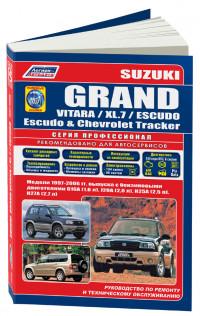
Руководство по эксплуатации, техническому обслуживанию и ремонту + каталог расходных запчастей автомобилей Chevrolet Tracker и Suzuki Escudo/Grand Escudo/Grand Vitara/Grand Vitara XL-7 1997-2006 годов выпуска с бензиновыми двигателями.
- Автор: —
- Издательство: Легион-Автодата
- Год издания: —
- Страниц: 534
- Формат: —
- Размер: —
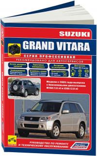
Руководство по эксплуатации, техническому обслуживанию и ремонту + каталог расходных запчастей автомобиля Suzuki Grand Vitara с 2005 года выпуска с бензиновыми двигателями объемом 1,6/2,0 л.
- Автор: —
- Издательство: Легион-Автодата
- Год издания: —
- Страниц: 446
- Формат: —
- Размер: —
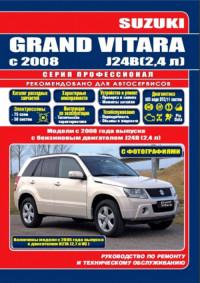
Руководство по эксплуатации, техническому обслуживанию и ремонту + каталог расходных запчастей автомобиля Suzuki Grand Vitara с 2008 года выпуска с бензиновым двигателем объемом 2,4 л.
- Автор: —
- Издательство: Легион-Автодата
- Год издания: 2015
- Страниц: 569
- Формат: —
- Размер: —
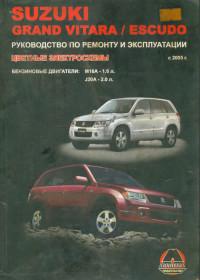
Руководство по эксплуатации и ремонту автомобилей Suzuki Grand Vitara и Suzuki Escudo с 2005 года выпуска с бензиновыми двигателями объемом 1,6/2,0 л.
- Автор: —
- Издательство: Монолит
- Год издания: 2009
- Страниц: 386
- Формат: DjVu
- Размер: 12,3 Mb

Руководство по эксплуатации и ремонту автомобилей Suzuki Grand Vitara и Suzuki Escudo с 2005 года выпуска с бензиновыми двигателями объемом 1,6/2,0/2,4/3,2 л.
- Автор: —
- Издательство: Монолит
- Год издания: —
- Страниц: 446
- Формат: —
- Размер: —

Руководство по эксплуатации и техническому обслуживанию автомобиля Suzuki Grand Vitara с 2005 года выпуска.
- Автор: —
- Издательство: MoToR
- Год издания: —
- Страниц: 240
- Формат: —
- Размер: —
Руководство по эксплуатации и техническому обслуживанию автомобиля Suzuki Grand Vitara с 2005 года выпуска.
- Автор: —
- Издательство: Suzuki Motor Corporation
- Год издания: 2005
- Страниц: 261
- Формат: PDF
- Размер: 2,5 Mb
Мультимедийное руководство по техническому обслуживанию и ремонту автомобиля Suzuki Grand Vitara серии SQ с 2005 года выпуска.
- Автор: —
- Издательство: —
- Год издания: —
- Страниц: —
- Формат: —
- Размер: 174,8 Mb
Руководство по эксплуатации, техническому обслуживанию и ремонту автомобиля Suzuki Grand Vitara с 2008 года выпуска.
- Автор: И.А. Карпов
- Издательство: Арус
- Год издания: —
- Страниц: 227
- Формат: PDF
- Размер: 202,5 Mb
Руководство по эксплуатации, техническому обслуживанию и ремонту автомобилей Suzuki Escudo/Grand Escudo/Grand Vitara, Mazda Levante и Chevrolet Tracker 1997-2005 года выпуска.
- Автор: —
- Издательство: Мир Автокниг
- Год издания: —
- Страниц: 464
- Формат: —
- Размер: —

Руководство по эксплуатации, техническому обслуживанию и ремонту автомобилей Suzuki Escudo/Grand Escudo/Grand Vitara, Mazda Levante и Chevrolet Tracker 1997-2005 года выпуска.
- Автор: —
- Издательство: Мир Автокниг
- Год издания: —
- Страниц: 464
- Формат: —
- Размер: —

Table of Contents
3
Abbreviations
4
Front Suspension
5
Free Wheel Device
6
Manual Free Wheel Performance
6
Automatic Free Wheel Performance
6
Free Wheel Types Description
7
Installation of «A» Type Manual Free Wheel
9
Installation of «B» Type Manual Free Wheel
11
Installation of «A» Type Automatic Free Wheel
13
Free Wheel Performance Checking
14
Installation of «B» Type Automatic Free Wheel
15
Replacement of «A» Type Manual Free Wheel
17
Replacement of «B» Type Manual Free Wheel
18
Replacement of «A» Type Automatic Free Wheel
19
Replacement of «B» Type Automatic Free Wheel
20
Front Suspension — Specified Torques
21
Front Suspension — Tools Needed
21
Electronic Fuel Injection System (Sequential Multiport Fuel Injection)
23
Electronic Fuel Injection System — General Description
25
Electronic Fuel Injection System Diagram
26
Electronic Control System
28
Engine Control Module (ECM)
32
On-Board Diagnostic System (Self-Diagnosis Function)
32
Fail-Safe Function
33
Throttle Position Sensor (TP Sensor)
34
Engine Coolant Temperature Sensor (ECT Sensor)
34
Exhaust Gas Recirculation (EGR) System (for Vehicle with EGR Stepper Motor)
35
Exhaust Gas Recirculation (EGR) System (for Vehicle with EGR Valve, Pressure Transducer and Solenoid Vacuum Valve)
36
Diagnosis
37
Diagnosis Flow Chart
38
Diagnostic Trouble Code Table (1 of 2 T/T/ and A/T)
39
A-1 ECM Power and Ground Circuit Check (Vehicle with Immobilizer)
41
A-1 ECM Power and Ground Circuit Check (Vehicle Without Immobilizer)
43
A-2 Malfunction Indicator Lamp («Check Engine» Light) Circuit Check
44
A-3 Malfunction Indicator Lamp («Check Engine» Light) Circuit Check
45
Code No. 13 Heated Oxygen Sensor Circuit (Signal Voltage Doesn’t Change)
46
Code no 14 ECT Sensor (Engine Coolant Temp. Sensor) Circuit (Low Temperature Indicated, Signal Voltage High)
47
Code no 15 ECT Sensor (Engine Coolant Temp. Sensor) Circuit (High Temperature Indicated, Signal Voltage Low)
48
Code no 21 TP Sensor (Throttle Position Sensor) Circuit (Signal Voltage High)
49
Code no 22 TP Sensor (Throttle Position Sensor) Circuit (Signal Voltage Low)
50
Code No. 24 VSS (Vehicle Speed Sensor) Circuit
51
Code No. 33 MAF Sensor (Mass Air Flow Sensor) Circuit
52
Code No. 34 MAF Sensor (Mass Air Flow Sensor) Circuit
53
Code No. 42 CMP Sensor (Camshaft Position Sensor) Circuit
54
Code No. 44 CTP Switch Circuit
55
Code No. 45 CTP Switch Circuit
56
Code no 51 EGR Valve (Stepper Motor or Its Circuit Open or Short)
57
B-1 Fuel Pump Circuit Check
58
B-1 Fuel Injector Circuit Check
59
B-3 Fuel Pressure Check
61
B-4 Idle Air Control System Check
63
B-5 EGR System Check (Vehicle with EGR Stepper Motor)
65
B-5 EGR System Check (Vehicle with EGR Solenoid Vacuum Valve)
66
B-6 Evaporative Emission Control System Check
67
Inspection of ECM and Its Circuits
68
M/T Vehicle
69
A/T Vehicle
71
Terminal Arrangement of ECM Coupler (Viewed from Harness Side)
74
On Vehicle Service
77
Electronic Control System Service
77
Mass Air Flow Sensor (MAF Sensor) Inspection
77
Automatic Transmission
79
Electronic Shift Control System Chart
80
Powertrain (Engine) Control Module (PCM/ECM)
80
Throttle Positon Sensor
81
Vehicle Speed Sensor
81
Transmission Range Switch
81
Brake Switch
82
Engine Coolant Temperature Sensor (ECT Sensor) Usage
82
O/D Cut Switch
82
Transfer 4L Switch
82
Mode Selector Switch
83
Fail Safe Function
83
Change Mechanism
83
Automatic Gear Shift Diagram
84
Power Mode
84
Gear Shift Diagram
84
TCC Lock-Up Diagram
84
Normal Mode
85
Transmission Unit Diagnosis
86
Manual Road Test
86
Electronic Shift Control System
87
Precaution in Identifying Diag. Trouble Code
87
Electronic Shift Control System — Diagnostic Flow Chart
88
Diagnostic Trouble Code Table (A/T Related Code)
89
Fail-Safe Table
89
Diagnostic Flow Chart a
90
Diagnostic Flow Chart B
91
Diagnostic Flow Chart C
92
Diagnostic Flow Chart D
94
Group 2 — Supplementary Service Manual
95
Heater and Ventilation
99
Heater and Ventilation — Diagram and General Description
100
Heater Control Operation
101
Mode Control Switch
101
Control Lever a
101
Control Lever B, C
101
A. Forced Ventilation
102
B. Outside Air-Introduced Heating
102
C. Inside Air-Circulated Heating
102
D. Head-Cooled/Feet-Warmed Heating
103
Trouble Diagnosis (Heater and Ventilation)
103
Heater and Ventilation — Wiring Circuit
104
Heater and Ventilation — On-Vehicle Service
105
Mode Control Switch Removal
105
Mode Control Switch Inspection
105
Mode Control Switch Installation
105
Mode Actuator Removal
106
Mode Actuator Inspection
106
Mode Actuator Installation
107
Heater Control Lever Assembly Removal
107
Inspection of Heater Blower Motor Switch
108
Heater Control Lever Assembly Installation
108
Control Cables Removal
109
Brakes
111
PSPV (Load Sensing Proportioning Valve) Assembly
112
Constitution
113
LSPV Operation
113
When LSPV Not at Work
114
When LSPV at Work
114
When Fail-Safe at Work
115
On-Vehicle Service LSPV (Load Sensing Proportioning Valve( R & I)
116
Remove and Install LSPV
116
After-Installation Inspection & Adjustment
117
Fluid Pressure Test
118
Body Electrical System
121
Combination Switch
122
Windshield Wipers (Front Wiper)
123
Wiper/Washer Switch Inspection
123
Intermittent Wiper Relay Circuit
123
Rear Window Wiper and Washer
124
Wiper and Washer Switches Inspection
125
Rear Wiper Intermittent Relay on Circuit
125
WASH Circuit
125
INT Circuit
126
Rear Fog Light Wiring Circuit Diagram
127
Rear Fog Light Wiring Inspection
128
Body Electric System Wiring Diagram
131
Suzuki Vitara 1.9 T. Diesel
135
Section 0A
147
Precautions for Vehicles Equipped with a Supplemental Restraint (Air Bag) System
149
Air Bag System Diagnosis
149
Air Bag System Servicing and Handling
150
General Servicing Precautions
152
Precautions for Catalytic Converter
154
Precautions for Electrical Circuit Service
155
Electrical Circuit Inspection Procedure
157
Open Circuit Check
157
Continuity Check
158
Voltage Check
158
Short Circuit Check (Wire Harness to Ground)
159
Intermittent and Poor Connection
160
Precautions for Installing Mobile Communication Equipment
161
Identification Information
162
Vehicle Identification Number
162
Engine Identification Number
162
Transmission Identification Number
162
Vehicle Lifting Points
163
Abbreviations List
165
Fasteners Information
167
Metric Fasteners
167
Fastener Strength Identification
167
Standard Tightening Torque
168
Maintenance and Lubrication
169
Maintenance Schedule
170
Maintenance Recommended under Severe Driving Conditions
172
Maintenance Service — Engine
173
Water Pump and Generator Drive Belt Inspection
173
Water Pump and Generator Drive Belt Replacement
173
Power Steering Pump And/Or A/C Compressor Drive Belts Inspection
174
Power Steering Pump And/Or A/C Compressor Drive Belts Replacement
174
Camshaft Timing Belt Replacement
175
Valve Lash Inspection (G16 Engine Only)
175
Engine Oil and Filter Change
175
Exhaust System Inspection
178
Ignition System
179
Spark Plugs Replacement
179
Distributor Cap and Rotor Inspection
179
Fuel System
180
Air Cleaner Filter Inspection
180
Air Cleaner Filter Replacement
180
Fuel Lines and Connections Inspection
180
Emission Control System
181
PCV (Positive Crankcase Ventilation) Valve Inspection
181
Evaporative Emission Control System Inspection
181
Fuel Filter Replacement
181
Chassis and Body
182
Clutch Pedal Inspection
182
Brake Discs, Pads, Brake Drums and Shoes Inspection
182
Brake Fluid Change
182
Parking Brake Lever and Cable Inspection
183
Tire Inspection and Rotation
183
Wheel Discs Inspection
184
Free Wheeling Hub Inspection
184
Wheel Bearing Inspection
184
Inspection of Front Wheel Bearing Grease
184
Suspension Inspection
185
Propeller Shafts and Drive Shaft Inspection
186
Transmission Oil Inspection and Change (for Manual Transmission)
187
Transfer and Differential Oil Inspection and Change
187
Steering System Inspection
188
Power Steering (P/S) System Inspection
189
All Hinges, Latches and Locks Inspection
189
Doors Inspection
189
Engine Hood Inspection
189
Final Inspection
190
Seats Inspection
190
Clutch (for Manual Transmission) Inspection
190
Brake Inspection
190
Recommended Fluids and Lubricants
191
Steering Check
191
Engine Check
191
Body, Wheels and Power Transmitting System Check
191
Engine General Information and Diagnosis
193
Engine General Information — Statement of Cleanliness and Care
195
General Information on Engine Service
195
Precautions on Fuel System Service
196
Fuel Pressure Relief Procedure
197
Fuel Leakage Check Procedure
197
Engine Diagnosis
198
On-Board Diagnostic System
198
Warm-Up Cycle
199
Driving Cycle
199
2 Driving Cycles Detection Logic
199
Freeze Frame Data
199
Data Link Connector (DLC)
200
Precaution in Diagnosing Trouble
201
Engine Diagnostic Flow Table
202
Malfunction Indicator Lamp (MIL) Check
205
Diagnostic Trouble Code (DTC) Check
205
Diagnostic Trouble Code (DTC) Clearance
205
Diagnostic Trouble Code (DTC) Table
206
Fail-Safe Table (Engine Diagnosis)
209
Scan Tool Data
210
Scan Tool Data Definitions
212
Visual Inspection (Engine)
214
Engine Basic Check
215
Engine Diagnosis Table
216
Inspection of ECM and Its Circuits — Voltage Checks
221
Resistance Check
225
Table A-1 Malfunction Indicator Lamp Circuit Check — Lamp Does Not Come «On» or Dims at Ignition Switch on (but Engine at Stop) — Wiring Diagram
226
Circuit Description
226
Table A-2 Malfunction Indicator Lamp Circuit Check — Lamp Remains «On» after Engine Starts
227
Table A-3 ECM Power and Ground Circuit Check — MIL Doesn’t Light at Ignition Switch on and Engine Doesn’t Start Though It Is Cranked up
228
Table A-3 ECM Power and Ground Circuit Inspection Table
229
DTC P0100 Mass Air Flow Circuit Malfunction — Wiring Diagram
230
DTC Detecting Condition and Trouble Area
230
DTC Confirmation Procedure
231
Troubleshooting (Engine Diagnosis)
231
DTC P0110 Intake Air Temp (IAT) Circuit Malfunction — Wiring Diagram
232
DTC Detecting Condition and Trouble Area Table
232
DTC Confirmation Procedure Steps
232
DTC P0115 Engine Coolant Temp. Circuit Malfunction — Wiring Diagram
234
DTC P0120 Throttle Position Circuit Malfunction
236
DTC P0121 Throttle Position Circuit Performance Problem
238
DTC P0130 HO2S-1 Circuit Malfunction
240
DTC P0133 HO2S-1 Circuit Slow Response
243
DTC P0134 HO2S-1 no Activity Detected
244
DTC P0135 HO2S-1 Heater Circuit Malfunction
245
Troubleshooting Table (DTC P0135)
246
DTC P0136 HO2S-2 Circuit Malfunction
247
DTC Confirmaton Procedure
248
Troubleshooting (DTC P0136)
248
DTC P0141 HO2S-2 Heater Circuit Malfunction
249
Troubleshooting (DTC P0141)
250
DTC P0171 Fuel System too Lean
251
DTC P0172 Fuel System too Rich
251
Troubleshooting (DTC P0171/P0172)
252
DTC P0300 Random Misfire Detected
253
DTC P0301 — P0304 Cylinder Misfire Detected
253
Troubleshooting (DTC P0300/P0301/P0302/P0303/P0304)
254
DTC P0335 Crankshaft Position Sensor Circuit Malfunction
255
Troubleshooting (DTC P0335)
257
DTC P0340 Camshaft Position Sensor Circuit Malfunction
258
DTC P0400 Exhaust Gas Recirculation Flow Malfunction
260
Troubleshooting (DTC P0400)
262
DTC P0403 Exhaust Gas Recirculation Circuit Malfunction
263
Troubleshooting (DTC P0403)
264
DTC P0420 Catalyst System Efficiency below Threshold
265
DTC P0443 EVAP Control System Purge Control Valve Circuit Malfunction
267
Troubleshooting (DTC P0443)
268
EVAP Canister Purge System Check
269
Vacuum Passage Inspection
269
Vacuum Hose Inspection
269
EVAP Canister Purge Valve and Its Circuit Check
270
EVAP Canister Purge Valve Inspection
270
EVAP Canister Check
271
DTC P0460 Fuel Level Sensor Circuit High Input
272
DTC P0500 Vehicle Speed Sensor Malfunction
274
Troubleshooting (DTC P0500)
275
DTC P0505 Idle Air Control System Malfunction
276
Troubleshooting (DTC P0505)
277
Idle Air Adjusting Screw and Its Passage Check
278
Fast Idle Air Valve
278
IAC Valve and Its Circuit Check
279
DTC P0601 Internal Control Module Memory Check Sum Error System Description
280
DTC P1408 Manifold Differential Pressure Sensor Circuit Malfunction
281
Troubleshooting (DTC P1408)
282
DTC P1450 Barometric Pressure Sensor Circuit Malfunction
283
DTC P1451 Barometric Pressure Sensor Performance Problem
283
DTC P1500 Engine Starter Signal Circuit Malfunction
284
DTC P1510 ECM Back-Up Power Supply Malfunction
285
Table B-1 Fuel Pump Circuit Inspection
286
Table B-2 Fuel Injectors and Circuit Inspection
287
Table B-3 Fuel Pressure Inspection
288
Table B-4 Fast Idle Air Valve System Inspection
290
Table B-5 A/C Signal Circuits Inspection
291
Engine Diagnosis — Special Tools
292
Engine Mechanical (1-Cam 16-Valves)
293
Engine Mechanical — General Description
294
Engine Lubrication
295
Cylinder Block
296
Crankshaft and Main Bearings
296
Pistons, Rings, Piston Pins and Connecting Rods
296
Cylinder Head and Valve Train
296
Engine On-Vehicle Service
297
Compression Check
297
Engine Vacuum Check
299
Oil Pressure Check
300
Valve Lash (Clearance)
302
Air Cleaner Element Removal
304
Air Cleaner Element Inspection
304
Air Cleaner Element Cleaning
304
Air Cleaner Element Installation
304
Air Inlet Pipe Removal
305
Air Inlet Pipe Installation
305
Cylinder Head Cover Removal
306
Cylinder Head Cover Installation
306
Throttle Body and Intake Manifold
308
Throttle Body and Intake Manifold Installation
310
Exhaust Manifold Removal
312
Exhaust Manifold Installation
313
Timing Belt and Belt Tensioner Removal
314
Timing Belt and Belt Tensioner Inspection
315
Timing Belt and Belt Tensioner Installation
316
Oil Pan and Oil Pump Strainer Removal
319
Oil Pan and Oil Pump Strainer Cleaning
320
Oil Pan and Oil Pump Strainer Installation
321
Oil Pump Removal
323
Oil Pump Disassembly
324
Oil Pump Inspection
325
Oil Pump Assembly
326
Oil Pump Installation
326
Rocker Arms, Rocker Arm Shaft and Camshaft Removal
328
Rocker Arms, Rocker Arm Shaft and Camshaft Inspection
331
Adjusting Screw and Rocker Arm Inspection
331
Rocker Arm Shaft Runout Check
331
Rocker Arm-To-Rocker Arm Shaft Clearance
331
Cam Wear Check
332
Camshaft Runout Check
332
Camshaft Journal Wear Check
332
Rocker Arms, Rocker Arm Shaft and Camshaft Installation
333
Valves and Cylinder Head Removal
337
Valves and Cylinder Head Disassembly
340
Valves and Cylinder Head Inspection
341
Valve Guides Check
341
Valves Check
341
Cylinder Head Check
343
Valve Springs Check
345
Valves and Cylinder Head Assembly
346
Valves and Cylinder Head Installation
348
Piston, Piston Rings, Connecting Rods and Cylinders Removal
350
Piston, Piston Rings, Connecting Rods and Cylinders Disassembly
351
Piston, Piston Rings, Connecting Rods and Cylinders Cleaning
351
Piston, Piston Rings, Connecting Rods and Cylinders Inspection
352
Pistons Check
352
Piston Pin Check
353
Piston Rings Check
354
Connecting Rod Check
354
Crank Pin and Connecting Rod Bearings
355
Piston, Piston Rings, Connecting Rods and Cylinders Assembly
356
Piston, Piston Rings, Connecting Rods and Cylinders Installation or Connection
358
Unit Repair Overhaul
360
Engine Assembly Removal
360
Engine Assembly Installation
364
Main Bearings, Crankshaft and Cylinder Block
366
Main Bearings, Crankshaft and Cylinder Block Removal
367
Main Bearings, Crankshaft and Cylinder Block Inspection
368
Main Bearings Inspection
369
Selection of Main Bearings
370
Rear Oil Seal Check
373
Flywheel Check
374
Cylinder Block Check
374
Honing or Reboring Cylinders
374
Main Bearings, Crankshaft and Cylinder Block Installation
375
Engine Mechanical — Special Tools
378
Engine Mechanical — Tightening Torque Specifications
380
Engine Fuel
381
Fuel System Description
381
Fuel System — On-Vehicle Service
382
Fuel Filter Removal
383
Fuel Filter Installation
384
Fuel Lines Inspection
384
Fuel Filler Cap
385
Fuel Tank
385
Fuel Tank Inspection
386
Fuel Tank Purging Procedure
387
Fuel Tank Installation
388
Engine and Emission Control System (Sequential Multiport Fuel Injection)
391
Engine and Emission Control System — General Description
393
Engine and Emission Control System — Diagram
394
Air Intake System
396
Fuel Delivery System
397
Electronic Control System Description
398
Engine & Emission Control Input/Output Table
402
Engine & Emission Control System — On-Vehicle System
403
Acceleration Cable Adjustment
404
Idle Speed/Idle Air Control (IAC) Duty Inspection
405
Throttle Body Removal
406
Throttle Body Cleaning
407
Throttle Body Installation
407
Idle Air Control Valve (IAC Valve) Inspection
408
Idle Air Control Valve (IAC Valve) Removal
408
Idle Air Control Valve (IAC Valve) Installation
408
Fuel Pressure Inspection
409
Fuel Pump — On-Vehicle Inspection
410
Fuel Pump Removal and Inspection
410
Fuel Pump Installation
411
Fuel Pressure Regulator Removal
411
Fuel Pressure Regulator Installation
411
Fuel Pulsation Damper Removal
412
Fuel Pulsation Damper Installation
412
Fuel Injector On-Vehicle Inspection
412
Fuel Injector Removal
413
Fuel Injector Inspection
414
Fuel Injector Installation
416
Engine Control Module (ECM) Removal
417
Engine Control Module (ECM) Installation
417
Mass Air Flow Sensor Inspection
418
Mass Air Flow Sensor (MAF Sensor) Removal
418
Intake Air Temperature (IAT) Sensor Removal
419
Intake Air Temperature (IAT) Sensor Inspection
419
Intake Air Temperature (IAT) Sensor Installation
420
Throttle Position Sensor (TP Sensor) Inspection
421
Throttle Position Sensor (TP Sensor) Adjustment
421
Throttle Position Sensor (TP Sensor) Removal
422
Throttle Position Sensor (TP Sensor) Installation
422
Engine Coolant Temperature Sensor (ECT Sensor) Removal
423
Engine Coolant Temperature Sensor (ECT Sensor) Inspection
423
Engine Coolant Temperature Sensor (ECT Sensor) Installation
424
Heated Oxygen Sensor-1 and -2 (HO2S-1 and HO2S-2) Inspection
424
Heated Oxygen Sensor-1 and -2 (HO2S-1 and HO2S-2) Removal
425
Heated Oxygen Sensor-1 and -2 (HO2S-1 and HO2S-2) Installation
425
Vehicle Speed Sensor (VSS) — On-Vehicle Inspection
425
Camshaft Position Sensor (CMP Sensor) Inspection
426
Camshaft Position Sensor (CMP Sensor) Removal and Installation
426
Crankshaft Position Sensor Inspection
426
Crankshaft Position Sensor Removal and Installation
426
Manifold Differential Pressure Sensor Check
427
Main Relay Inspection
428
Fuel Pump Relay Inspection
428
Fuel Cut Operation Inspection
429
EGR System Inspection Using Suzuki Scan Tool
430
EGR System Removal
430
Evaporative Emission Control System
431
EGR System Inspection
431
PCV System
431
PCV Hose
431
PCV Valve
432
Engine and Emission Control System — Tightening Torque Specifications
433
Engine and Emission Control System — Special Tools
433
Section 6F — Ignition System
435
Ignition System — General Description
436
Ignition System Diagnosis Table
437
Diagnostic Flowtable (When Engine Cranks but Does Not Start)
437
Ignition Spark Test
438
High-Tension Cords
438
Spark Plugs
439
Noise Suppressor
439
Distributor Power Supply
440
Distributor Cap and Rotor
440
Ignition Coil Circuit
440
Igniter Circuit
440
Ignition Timing — Inspection and Adjustment
441
Distributor Unit View
442
Distributor Unit Removal
442
Distributor Unit Installation
443
Ignition System — Special Tools
444
Exhaust System
445
Exhaust System Diagram
446
Exhaust System Maintenance
447
Exhaust System On-Vehicle Service
447
Exhaust Manifold
447
Muffler
447
Immobilizer Control System
449
Immobilizer Control System — General Description
450
Ignition Key
451
Coil Antenna
451
Immobilizer Control Module
452
Ecm/Pcm
452
On-Board Diagnostic System (Immobilizer Control Module)
452
Immobilizer Control System Diagnosis
454
Diagnostic Flow Table (Immobilizer Control System)
456
Diagnostic Trouble Code (DTC) Check (Immobilizer Control Module)
457
Diagnostic Trouble Code (DTC) Check (ECM/PCM)
458
Diagnostic Trouble Code Table — Immobilizer Control Module
459
Diagnostic Trouble Code Table — ECM/PCM
459
Table a DTC Is Not Output from Diagnostic Output Terminal
460
Table B Immobilizer Indicator Lamp Check (Immobilizer Indicator Lamp Does Not Light at Ignition Switch On)
461
Table C Immobilizer Indicator Lamp Check (Immobilizer Indicator Lamp Remains on after Engine Starts)
462
DTC11 Transponder Code Not Matched
463
DTC31 Transponder Code Not Registered
463
DTC12 Fault in Immobilizer Control Module
463
DTC13 no Transponder Code Transmitted or Coil Antenna Opened/Shorted
464
DTC 21 Ecm/Immobilizer Control Module Code Not Matched (Immobilizer Control Module Side)
466
DTC81 Ecm/Immobilizer Control Module Code Not Matched (ECM/PCM Side)
466
DTC84 — Ecm/Immobilizer Control Module Code Not Registered
466
DTC22 Ignition Switch Circuit Open/Short
467
DTC23 no Ecm/Immobilizer Control Module Code Transmitted from ECM/)CM or DLC Circuit Opened/Shorted
468
DTC83 no Ecm/Immobilizer Control Module Code Transmitted from Immobilizer Control Module or DLC Circuit Opened/Shorted
468
DTC82 (P1622) Fault in ECM/PCM
469
Inspection of ECM/PCM, Immobilizer Control Module and Its Circuit
470
Immobilizer Control System On-Vehicle Service
472
Precautions in Handling Immobilizer Control System
472
Immobilizer Control Module Removal
473
Immobilizer Control Module Installation
473
How to Register Ignition Key
474
Procedure after Immobilizer Control Module Replacement
475
Procedure after ECM/PCM Replacement
476
Immobilizer Control System — Special Tools
476
Suzuki Grand Vitara, Vitara, Escudo, Chevrolet Tracker 1997-2006. Руководство по ремонту и техническому обслуживанию
- Разместил: klays067;
- Прочитано: 3 944;
- Дата: 10-03-2019, 15:59;
-


Руководство на русском языке по эксплуатации, техническому обслуживанию и ремонту + каталог расходных запчастей автомобилей Chevrolet Tracker и Suzuki Escudo/Grand Escudo/Grand Vitara/Grand Vitara XL-7 1997-2006 годов выпуска с бензиновыми двигателями.

Внимание! Нажимая на ссылку «скачать» Вы обязуетесь, после ознакомления, удалить скаченный файл со своего компьютера.
Всё содержимое сайта autosoftos.com взято из свободных источников, и также свободно распространяется.
Если это Вы являетесь автором данного материала, то, пожалуйста, свяжитесь с нами, для того чтобы обеспечить пользователям, приятную и удобную альтернативу, после ознакомления, покупки качественного «оригинала» непосредственно от издателя. Администрация сайта не несёт никакой ответственности за противоправные действия, и какой либо ущерб, понесённый правообладателями.
 0
0
 0
0
+3611

Информация
Посетители, находящиеся в группе Гости, не могут оставлять комментарии к данной публикации.
Реклама
Новости
- Wurth WOW 5.29.02R2RUS [2014]
- Установка сигнализации на Volvo S40
- Установка сигнализации на Volkswagen Golf 1998 — 2007
- Bimmer-Tool 3.5.26 Expert
- Установка сигнализации на Volkswagen Vento
- BimmerLink for BMW and Mini 2.29.0-5264 Full
- Установка сигнализации на Volkswagen Jetta 2000 — 2008
- Предохранители Volvo FH 13 и реле с обозначением и схемами блоков
- Предохранители Volvo XC90 и реле с обозначением и схемами блоков
- Прошивка Bosch 797+ подробная, проверенная инструкция
Опрос
Календарь
Пароль для всего скачанного: «suzuki-club.kz» (без кавычек)
SUZUKI Jimny. Руководство для владельца

Язык: Русский
Размер: 7.3 Мб
Формат: PDF
 Скачать
SUZUKI SX4. Руководство для владельца

Язык: Русский
Размер: 45.6 Мб
Формат: PDF
Скачать
SUZUKI SX4. Руководство по эксплуатации

Язык: Русский
Размер: 6.5 Мб
Формат: PDF
Скачать
SUZUKI Grand Vitara / Escudo c 2005 г. Руководство по ремонту и эксплуатации

Язык: Русский
Размер: 12.4 Мб
Формат: DjVu
Скачать
SUZUKI Swift / Ignis с 2000 г. Устройство, техническое обслуживание и ремонт

Язык: Русский
Размер: 129.4 Мб
Формат: PDF
Скачать
SUZUKI Grand Vitara / Grand Vitara XL-7 / Grand Escudo / Escudo 1997-2004. Устройство, техническое обслуживание и ремонт

Язык: Русский
Размер: 136.3 Мб
Формат: PDF
Скачать
SUZUKI Wagon R. Руководство по ремонту и эксплуатации

Язык: Русский
Размер: 76.9 Мб
Формат: PDF
Скачать
SUZUKI Liana. Руководство для владельца

Язык: Русский
Размер: 5.5 Мб
Формат: PDF
Скачать
SUZUKI XL-7 с 2007 г. Руководство для владельца

Язык:
Английский
Размер: 4.3 Мб
Формат: PDF
Скачать
SUZUKI XL-7 с 2007 г. Руководство по ремонту

Язык:
Английский
Размер: 62.7 Мб
Формат: PDF
Скачать
Suzuki Vitara/Escudo, Geo Tracker & Mazda Levante 1988-1998. Устройство, техническое обслуживание и ремонт

Язык: Русский
Размер: 36.1 Мб
Формат: PDF
Скачать
Пароль для всего скачанного: «suzuki-club.kz» (без кавычек)