- Manuals
- Brands
- WEICHAI Manuals
- Engine
- WD615
- Manual
-
Contents
-
Table of Contents
-
Bookmarks
Quick Links
Contents
…1
1.1 Daily Maintenance………………………………………………………….3
……………………………………………………………………….26
Engine ………………………………………………………………………….42
…44
Related Manuals for WEICHAI WD615
Summary of Contents for WEICHAI WD615
-
Page 1: Table Of Contents
1.7 Check Air Filter Element …………………………………………….……17 1.8 Check and Adjust Valve Clearance ……………………………….……19 1.9 Check and Adjust Fuel Supply Advance Angle …………………….….24 Chapter II Key Points about Assembling or Disassembling WD615 Diesel ………………………………………………..……………………..26 Engines 2.1 Assemble Injection Nozzle, Camshaft and Cylinder Liner……………26 2.1.1 Assemble Injection Nozzle …………………………………………..26…
-
Page 2
3.1.2 Case Description about Diesel Engine Cannot Be Started (2) ……48 3.2 Stop Soon after Starting ………………………………………..……..50 3.3 Insufficient Output ………………………………………………………52 3.3.1 Case Description about Insufficient Output (1) ……….……………53 3.3.2 Case Description about Insufficient Output (2) …………………….54 3.3.3 Case Description about Insufficient Output (3) ……………………..55 3.4 Fuel Consumption Is Too High ………………………………………….57 3.5 Black Smoke Exhaust ……………………………………………………59 3.6 Oil Is Gathered in Inlet and Exhaust Vents of Turbocharger and Inlet… -
Page 3: Chapter I Maintenance For Wd615/Wd10/Wd618/Wd12 Diesel Engines
Replace fuel filter element and oil filter element; Clean and check air filter element. Replace it every 5 times of cleaning. ● Maintenance interval: Maintenance should be done in time at service stations authorized by Weichai Power according to the following requirements:…
-
Page 4
Recommend CF-4 oil to be used in Weichai Power diesel engine series. High quality oil is allowed to replace low quality oil. The specification of common oil is as follows: Viscosity grade 0W-30 5W-30 10W-30 15W-40 20W-50 Applied -40 ~ 30 ℃… -
Page 5: Daily Maintenance
1.1 Daily Maintenance ● Inspection: ● Check the oil level ; ● Check the coolant level ; ● Check the fuel level; ● Check whether the fan is damaged; ● Check whether the V-belt is cracked or scratched; ● Check whether the accessories are fixed well; ●…
-
Page 6
Before starting the engine one should check coolant level, and check whether the cooling system is leaking. Check whether water temperature is at the required range or not when the engine is running. When water temperature is too high, please check: ①… -
Page 7: Periodic Maintenance
1.2 Periodic Maintenance Regular maintenance should be done as per the following table. If the operating condition is heavy dust content or the engine running on starting- stopping frequently, the regular maintenance period should be shortened accordingly . Learning and thinking:…
-
Page 8: Maintenance Interval
1.3 Maintenance Interval (WG I ) (WG II ) (WG III ) Under tough operating condition (e.g. cold or hot weather, high dust content, Annual running short-distance transportation, mileage of the Annual running service in construction vehicle less mileage of the site and bus, municipal than 60,000 vehicle more…
-
Page 9
● The first inspection, routine inspection and maintenance interval WGⅡ WGⅢ Operating 2×10⁴ km 6×10⁴ km 6×10⁴ km Annual running Annual running Annual running Condition mileage mileage mileage Item <20,000 km <60,000 km <60,000 km Running The first Running Running 1,000~1,500 km inspection 1,500~2,000 km… -
Page 10
● Oil replacement period in vehicle maintenance system WGⅡ WGⅢ Operating Annual running Annual running Annual running mileage<2×10⁴ mileage< mileage> Condition 6×10⁴ km 6×10⁴ km Item Running Running Running The first 1,500~2,000 1,500~2,000 inspection 1000~1500 km Every 1×10⁴ Every 1.5×10⁴ Periodical Every 500 km inspection… -
Page 11
● Maintenance items Items Replacement Adjustment Inspection ●Air filter ●Oil ●Air intake system ●Oil filter ●Tighten pipe clamps ●Valve ●WD 3 ●Fuel filter ●Tighten V-belts clearance ●Coolant ●Inspect and adjust the ●Air filter injection fuel pump on test bench Items Replacement Adjustment Inspection… -
Page 12: Maintenance Contents
1.4 Maintenance Contents Daily maintenance ● Preventive maintenance should be done every day in order to understand the engine’s condition. ● Before starting the engine one should check the oil level, coolant level and the fuel level. ● Inspect the oil level height ●…
-
Page 13
● Inspect the coolant level ● Inspect the coolant level through the vitreous view hole , if the coolant is not sufficient, open the inlet cover and fill into the coolant. Note: When opening the inlet ※ cover, one must press down the exhaust button firstly to prevent hot coolant from injuring people ●… -
Page 14
● Inspect the V-belts ● Inspect the V-belts with your eyes to find if there is any crack or scratchon the V-belts. Replace them if necessary. ● Drain off the water and deposit from the small filter cup fitted on the fuel delivery pump. -
Page 15: Replacement Of Oil And Oil Filter
1.5 Replacement of Oil and Oil Filter. Maintenance items of various maintenances ● Replacement of the oil and oil filter Note: The replacement interval of ※ oil under proper using condition cannot beyond 250 h(10,000 Kilometers) ● Tool: 32 mm open-ended wrench ●…
-
Page 16
● Tool: The special wrench for filter ● Clean the end surrounding of the filter, and remove it ● Install the new oil filter ● Note : Adjust the seal ring and smear some lubricating oil on it while fitting the oil filter . ●… -
Page 17
● Run the engine at idling speed and check the filter to find whether it leaks or not ● Stop the engine and make the oil run into the sump from the upper parts 5 minutes later, then check the oil level, fill oil up to the upper limit if necessary .… -
Page 18: Replace Fuel Filter
1.6 Replace Fuel Filter ● Tool : 13 mm open-ended wrench ● Clean the end surrounding of the fuel filter, unloosen the upper bolt and disassemble the fuel filter. ● Install the new fuel pre-filter element and filter element ● Install the replaced fuel filter on the bracket and tighten the bolt. ●…
-
Page 19: Check Air Filter Element
Press the fuel delivery pump plug till the fuel drained off from the draining bolt outlet does not contain air, then tighten the bolt . ● Check the air intake system. ● Check whether the air intake rubber pipes are aging or cracked, the steel wire hoop is loosening .…
-
Page 20
● The max air intake resistance of the engine is 7 kpa. Air intake resistance must be checked when diesel engines run at rated speed and in full load. When the resistance reaches the max. limit permitted, one should clean or replace air filter element as per relevant requirements from suppliers. -
Page 21: Check And Adjust Valve Clearance
1.8 Check and Adjust Valve Clearance ● 1 3 mm sleeve wrench ● Disassemble 6 cylinder head covers ● Tool: 32 mm wrench for turning the crankshaft ● Turn the flywheel until its OT scale and the mark on its housing are aligned, push the piston to the position of TDC of compression stroke of 1st…
-
Page 22
● After WEVB system is used, the adjustment method of exhaust valve clearance is as follows (see Fig. 2 for part serial numbers) 1. Valve clearance adjusting nut 2. Regulating bolt assembly 3. Exhaust valve rocker arm assembly 4. Steel ball 5. Valve rocker arm piston 6. -
Page 23
● Then as shown in Fig. 3, insert the clearance gauge between No. 5 valve rocker arm piston and the exhaust valve rod end or valve rod cap. By turning No. 2 regulating bolt, adjust the valve clearance to 0.25 mm. Tighten check nut. -
Page 24
The piston of 1 cylinder is at TDC of the compression stroke . ※ Check and adjust the valve clearance as step A (I-air intake Valve ※ E-air Exhaust valve). Adjust the clearance by gauge and tighten the fixing nut of rocker ※… -
Page 25
Adjust the valve clearance as step B ※ Loosen the fixing nut of rocker arm, adjust the clearance by gauge ※ then tighten the nut again. Step B Tool: 13 mm sleeve wrench ※ Install the gasket and cylinder head cover ※… -
Page 26: Check And Adjust Fuel Supply Advance Angle
1.9 Adjustment of Fuel Supply Advance Angle Torque wrench, 18# open-ended wrench, auxiliary material : 242 thread sealant Operation as follows : ● Turn the flywheel until the pistons of 1st and 6th cylinders reach the top dead center. ● Counterclockwise turn the flywheel to the scale required before pistons reach the top dead center.
-
Page 27
Turn the flywheel to the accurate scale required. ※ Tighten bolts with the torque of 120-150 Nm and smear 242 ※ sealant on the thread ● Check the fuel supply advance angle. Turn the engine until fuel pump supplying fuel for 1st cylinder, and ※… -
Page 28: Chapter Ii Key Points About Assembling Or Disassembling Wd615 Diesel
Chapter II Key Points about Assembling or Disassembling WD615 Diesel Engines 2.1 Assemble Injection Nozzle, Camshaft and Cylinder Liner 2.1.1 Assemble Injection Nozzle ● Burnish the bottom plane of the cylinder body, clear tilting oil passage and main & slave oil passage with compressed air, then rub the bottom plane.
-
Page 29: Assemble Cylinder Liner
● Rub camshaft, check and make sure no scratching, then put the camshaft in its bore. ● Assemble the thrust flake of camshaft, and loosen hexagon bolt, then tighten it. ● Smear the thrust flake with lubricating oil, then rotate camshaft to check the axial clearance, and make sure it’s rotating freely with no retarding.
-
Page 30
● Press the cylinder liner into the bore with presser machine. ● Cylinder liner is above the top plane of cylinder body of 0.05~0.10 mm. ● Check cylindricity and ellipticity inside the bore. -
Page 31: Pre-Assemble & Assemble Crankshaft
2.2 Pre-assemble & Assemble Crankshaft 2.2.1 Assembling Steps (1) ● Heat flange to 290 ℃ , and its color becomes yellow. Heat crankshaft gear to 180 ℃ (the heating temperatures are recommending results, they should be due to assembling condition) Note :…
-
Page 32: Assembling Steps (2)
2.2.2 Assembling Steps (2) ● Clean the bottom plane of cylinder body with 755 abluent or industrial alcohol. ● Mount main bearing shell, top thrust flake, and coat oil. ● Sling/Hang up crankshaft, blow oil passage bore with compressed air and rub main journal and connecting stick journal with towel, then gently put it in the engine body.
-
Page 33: Assemble Cylinder Body
2.3 Assemble Cylinder Body ● Insert guiding stick into the bolt bore of main bearing as Figure, then hang up then crankshaft and turn 180°, then gently put it into the engine body along the guiding stick. Note : Matching number of crankcase ※…
-
Page 34: Pre-Assemble & Assemble Connecting Stick And Piston
● Coat rear oil seal of crankshaft with sealant, then mount it on the crankshaft. Note : Coat rear oil seal with sealant, and sealant should be continuous. ● Press the oil seal into cylinder body assembly with proper tool. Note: Must coat the tool with lubricating oil.
-
Page 35
Note: Coat combustion chamber ※ Coat small end bore of connecting rod, piston pin and its bore with ※ lubricating oil. ● The sequence of assembling piston rings is: helical spring oil ring, taper-face ring, trapezoidal barrel-face ring. Note: Pay attention to the sequence of assembling piston rings and ※… -
Page 36
● The weight difference between each connecting rod assembly is 29 g. There are C, D, E, F, G, H, J, K and L groups. The connecting rods assembled on the same engine should be in the same weight group. And the connecting rod body and its corresponding connecting rod cap should have the matching numbers. -
Page 37
Note: Check whether piston rings in ring groove moves freely or not, ※ make sure no blocking. The angle between the open end of the first ring and piston pin ※ axial line should be 30°±5°, and make sure there is a degree of 120° between each open end of piston pins. -
Page 38: The Assembly Of The Timing Gear Housing
● Tighten connecting rod bolts in accordance with process requirement. Tighten connecting rod bolts of the 1st and 6th cylinders first, turn engine 120°, then tighten connecting rod bolts of the 2nd and 5th, and turn engine 120°, then tighten connecting rod bolts of the 3rd and 4th cylinders.
-
Page 39
gear housing, insert hexagonal bolts with gaskets and tighten them. The level of the cover to the left groove. a. Smear general lithium grease on the shaft. b. Tightening torque: 60±5 Nm. c. Turn bolts 90°, and the torque range is 100~125 Nm. Replace those bolts that not reach required torque range. -
Page 40
Appendix: fitting of gears in gear case… -
Page 41: The Assembly Of Flywheel Housing And Flywheel
2.6 The Assembly of Flywheel Housing and Flywheel 2.6.1 The Assembly of Flywheel Housing: ● Polish, clean, remove grease and coat sealing glue on the surface of cylinder block and fly wheel housing. ● Lift fly wheel housing and pre-assemble fly wheel housing bolts. Notice: Cylindrical pin of end back of cylinder block must match with ※…
-
Page 42: The Assembly Of Front Oil Seal And Camshaft Timing Gear
● Install flywheel and tooth ring of fly wheel in the crankshaft. Notice: Coat antirust oil on the inner surface of the flywheel. ※ ● Insert flywheel bolts and tighten them. Notice: Coat lubricant on thread of ※ bolts and supporting block before inserting bolts.
-
Page 43
clearance of gears is 0.034~0.265 mm, and recommended inner control range is 0.10~0.25 mm. ● Hit a pin into the front of the timing gear house. ● Install camshaft gear cover gasket and camshaft gear cover. ● Tighten inner hexagonal cylindrical head screws and matching saddle-shaped spring gaskets. -
Page 44: Tightening Torque And Tightening Method Of Main Bolts Of Diesel Engine
2.8 Tightening Torque and Tightening Method of Main Bolts of Diesel Engine Tightening Torque(Nm)+Turning Time of Name Angle reuse Main bearing bolts 250+30 Connecting rod bolts 120+(90 ° +/-5 °) at the same time M14*1.5 reach 170-250 N·m Cylinder head Main bolt for 200+10+2*(90°+/-5°)at the same cylinder head…
-
Page 45
Bolt for air exhaust pipe 50-70 Bolt for rocker- arm seat 100+10 Press nut for air 200+20 compressor gear M18*1.5 Press nut for fuel pump gear 450-500 M24*1.5 Fixing bolt for tension pulley Fixing bolt for fuel pump coupling bearing cover Tension bolt for 130+20 / 150+15… -
Page 46: Chapter Iii Introduction Of Fault Case For Wd615/618 Diesel Engine
Chapter III Introduction of Fault Case for WD615/618 Diesel Engine Failure diagnosis and remedy principle ● When a diesel engine has faults, we apply a method that the easier part first and remove faults one by one. ● Do not replace any part haphazard until find root of the fault.
-
Page 47
Neutral position switch Shut-down switch under vehicle… -
Page 48: Case Description About Diesel Engine Cannot Be Started (1)
3.1.1 Case Description about Diesel Engine Cannot Be Started (1) 1. Starting line, starter and battery are normal, but Diesel Engine cannot be started by starter for several times, so eliminate starting system failure. 2. Check low and high pressure fuel passage and exhaust air and engine can start;…
-
Page 49
Thread of fuel inlet of coarse filter is damaged and its fuel inlet is cracked Learning and thinking:… -
Page 50: Case Description About Diesel Engine Cannot Be Started (2)
3.1.2 Case Description about Diesel Engine Cannot Be Started (2) ● Starter operates normally, but engine can not be started. ● We find there is wax in low pressure fuel passage after checking, which causes fuel loses fluidity and blocks fuel passage and filter element.
-
Page 51
Ignition key switch Starter Attached table: fault cause and remedy. cause remedy 1. Fuel intake filter screen of supply Clear away the dirt and check if the pump or hose clogged fuel is clean Drain off the air, check the sealing of 2. -
Page 52: Stop Soon After Starting
3.2 Stop Soon after Starting ● Check whether air entered or leaked or choked in low press fuel passage. Come into next step if it still can not be started. ● Check whether gear pump is working. Come into next step if it still can not be started.
-
Page 53
Case description about stop soon after starting ● Diesel engine can be started, but after starting it exhausted black smoke. Inspect air filter element and air passage are circulated and turbocharger is normal. ● Find fuel is mixed in water after inspecting low pressure fuel passage and fuel. -
Page 54: Insufficient Output
Attached table: the inspection and removal of fault when engine starts soon stops Cause Remedy Dismantle and clean away dirt and water Fuel filter clogged replace the filter element if necessary Air entered into the Check fuel pipe and sealing of the connector fuel system tighten air venting bolt, and drain off the air Supply pump doesn’t…
-
Page 55: Case Description About Insufficient Output (1)
3.3.1 Case Description about Insufficient Output (1) ● Insufficient output. ● Inspect fuel passage and whether fuel is normal. ● Inspect air filter element and air inlet pipe, and then find there is an opening of 15cm under intercooler. Case analysis Air inlet pipe leaks air Remedy Replace intercooler…
-
Page 56: Case Description About Insufficient Output (2)
3.3.2 Case Description about Insufficient Output (2) ● There is insufficient output when engine is in large load, but there is no big smoke. ● Inspect air filter, turbocharger and initial angle of fuel supply are normal. ● Inspect whether low pressure fuel passage and every pipe are leaked.
-
Page 57: Case Description About Insufficient Output (3)
3.3.3 Case Description about Insufficient Output (3) ● Output of the engine is insufficient, but engine doesn’t exhaust black smoke clearly. ● Check fuel passage, fuel and initial angle of fuel supply are normal. ● Customers work in desert area, they find air filter elements are blocked and air inlet pipes are very dirty after checking.
-
Page 58
Attached table: fault cause and remedy Air intake clogged (air Check air cleaner and air intake pipe, clean or cleaner logged) replace filter element Exhaust back pressure is Check the valve-timing and exhaust pipe adjust too high and repair Insufficient pressure in Check and block up the leakage of pipeline supercharging system Faults in turbocharger… -
Page 59: Fuel Consumption Is Too High
3.4 Fuel Consumption Is Too High ● Check whether low pressure fuel passage and quality of fuel are normal. Come into next step if normal. ● Check whether air filter element, air inlet pipe and turbocharger are normal. Come into next step if normal. ●…
-
Page 60
Checkout process of the injector Attached table: fault cause and remedy Air intake clogged(air cleaner Check air cleaner and air intake pipe, then choked) clean them Exhaust back pressure is too Check exhaust pipe and brake valve, then high clean them Poor quality of fuel Renew the fuel according to requirements Fuel line choked… -
Page 61: Black Smoke Exhaust
3.5 Black Smoke Exhaust ● Smoke emission is a very important target representing the fuel condition. The abnormal smoke emission indicates that there is problem with the combustion. The colors of the abnormal smoke are usually black, blue and white. Emitting black smoke indicates that the diesel fuel does not burn very well.
-
Page 62
Case description about black smoke exhaust ● When diesel engine is operating, there is a lot of smoke and fuel consumption is too high. ● Inspect air filter, turbocharger, valve clearance and initial angle of fuel supply are normal. ● There is no fuel leakage in low pressure fuel passage and high pressure fuel pipe. -
Page 63
Attached table: fault cause and remedy Air intake is not free or exhaust back pressure is Clean too high Poor quality of fuel Clean and renew Incorrect timing of valve Adjust according to requirements gear or fuel supply Poor atomizing Check, repair or replace injector Excessive injection quantity Check and adjust (by manufacturer) -
Page 64: And Exhaust Pipe
3.6 Oil Is Gathered in Inlet and Exhaust Vents of Turbocharger and Inlet and Exhaust Pipe. ● Check oil dipstick. Come into next step if oil level of oil pan is not high. ● Check whether turbocharger is good. Come into next step if yes.
-
Page 65: Oil Is Gathered In Inlet And Exhaust Vents Of Turbocharger And Inlet
Case description ● Oil is gathered in inlet and exhaust vents of turbocharger and inlet and exhaust pipe and there is a lot of smoke when a new engine is operating without load. ● Check oil dipstick and then find oil level of oil pan is not high. ●…
-
Page 66
Fault inspection and removal of gathered oil in inlet and exhaust vents of turbocharger, inlet and exhaust pipe. The sealing of turbocharger cease Repair or replace turbocharger to be in effort The gas-oil separator cease to be Replace in effect Drain off unnecessary oil according Lub-oil level in oil sump is too high to requirements… -
Page 67: Lub-Oil Pressure Is Too Low
3.7 Lubricant-oil Pressure Is Too Low. ● Check whether oil level of oil pan is too low or insufficient. Come into next step if not. ● Check whether oil brand is satisfied to relevant rules. Come into next step if not. ●…
-
Page 68: Case Description About Lub-Oil Pressure Is Too Low (1)
3.7.1 Case Description about Lub-oil Pressure Is Too Low (1) ● Lub-oil pressure is low. Oil level of oil pan is normal, but oil brand is not satisfied to requirement. ● Fault is not removed after replacing oil and oil filter and cleaning oil cooler.
-
Page 69: Case Description About Lub-Oil Pressure Is Too Low (2)
Limiter valve of main oil passage Limiter valve of main oil passage ● Lub-oil pressure is low. Oil level of oil pan is normal, but oil brand is not satisfied to requirement. ● Fault is not removed after replacing oil and oil filter and cleaning oil cooler.
-
Page 70
Oil filter Clean strainer… -
Page 71
Attached table: fault cause and remedy 1. Oil level in oil sump is too low Check oil leakage, add oil 2. Faults in pressure regulating Check valve clean and repair valve of main oil passage Check strainer and connector check 3. -
Page 72: Cooling Water Temperature Is Too High
3.8 Cooling Water Temperature Is Too High. ● Check whether water level of water tank, water belt and oil level of oil pan are normal. Come into next step if normal. ● Check thermostat. Come into next step if normal. ●…
-
Page 73
Remedy Add air intake on engine shell and clean water tank Add air vents on both sides of shell (left side) Because fan sucks air from ground, water tank is too dirty and Vehicle has no air radiator vent of water vent, so it only tank is choked, which cause engine too hot… -
Page 74
Check belt pulley with 4-5 kg force and press down 15-20 mm 1.Water level in water tank is too low Check water leakage, add water 2.Water tank clogged Check or repair Adjust tension according to 3.The belt of water pump loosened requirements 4.Water pump gasket damaged, Check and repair, or replace… -
Page 75: The Oil Mixed With The Water
3.9 The Oil Mixed with the Water ● There is water in the oil. First check the cylinder head and the air compressor. Change the relevant components if there is any crack. Check whether the cylinder gasket is washed off or damaged letting cooling water mix with the oil.
Продолжаем сборку двигателя. Настало время поршней, шатунов и прочего. Для начала укладываем двигатель горизонтально.
Прежде всего, взвешиваем все шатуны и поршни. Шатуны взвешиваем вместе с крышками и болтами. Поршни без упаковки и без пальцев.
Выясняем разницу в весе шатунов в 17 г, поршней 20 г. С поршнями конечно перебор. Поехали менять. Наконец подобрали. Затем группируем по весу — самый тяжёлый шатун к самому лёгкому поршню. Пальцы роли не играют — разница 1 г.
На выходе имеем по весу группу поршень-палец-шатун с разницей около 15 г.
Далее требуется нагреть поршни до 80 градусов для правильной установки пальцев. Решили приспособить для этого теплогенератор и чьё-то старое литьё.  Стопорные кольца с одной стороны установили заранее.
Пока поршни отогревались, протерли хорошенько втулки шатунов и постели вкладышей, расконсервировали пальцы, приготовили масло и кисточку.
Дозревшие поршни берём по одному, мажем палец, вставляем в поршень, совмещаем со втулкой шатуна, устанавливаем, стопорим.
Теперь очень тонкое занятие — установка поршневых колец без съёмника. Поршни этих дизелей имеют три кольца — 2 компрессионных и 1 маслосъёмное. На новых кольцах нанесена маркировка «ТОР» и заботливым дядюшкой Ляо вложена картинка по монтажу и типу колец. То есть перепутать наверняка никак.
Первым делом одеваем пружину маслосъёмного кольца и само кольцо.
Затем очень аккуратно одеваем второе компрессионное кольцо, не допуская его попадания в канавку верхнего кольца. Первое уже совсем просто. Разводим замки колец на 120 градусов. При этом замок в пружине должен попасть на разрез кольца — там идёт замочная направляющая из проволоки.
Ну вот и всё в сборе. Берём поршень в горизонтальное положение и промазываем маслом все кольца, следя за тем, чтобы масло попало на дно канавок. Устанавливаем обжимную ленту на поршень. Следим, чтобы все кольца легли в свои канавки, для верности постукиваем лёгким молотком по обжимке. Поршень готов к установке в гильзу. Мажем маслом постель вкладыша, устанавливаем верхнюю часть вкладыша, так же поступаем с крышкой.
Кроме того, понадобится динамометрический ключ и кусок проволоки, изогнутый крючком. Понадобится для протаскивания шатуна к шейке вала.
Смазываем гильзу маслом. Вставляем поршень шатуном в гильзу. Напарник со стороны вала цепляет крючком шатун за отверстие для болта. Для удобства проворачиваем вал таким образом, чтобы проходила рука к шатуну. Твёрдой деревяшкой (можно рукояткой молотка) постукиваем по поршню, равномерно по окружности. Напарник тянет крючком. Следим, чтобы обжимка не зашла в гильзу вместе с поршнем. Подтягиваем шатун к шейке, закрываем крышкой, затягиваем от руки шатунные болты. С учётом расположения шеек вала порядок установки поршней такой: 1-6, 2-5, 3-4.
Для затяжки шатунных болтов переворачиваем двигатель крышками вверх. И да. Шатунные болты заменяем новыми. Хотя и говорят, что можно и ещё раз их поставить. Нет. Дальше станет ясно почему.
Согласно китайских книжек, момент составляет 250 нм. Протягиваем в том же порядке, в каком и устанавливали поршни. Просто так удобнее.
Для начала тянем болты с моментом 120 нм. Затем наносим на головки болтов линии. Доворачиваем болты на угол примерно 90 градусов, при этом момент должен быть 250 нм.
И тут началось. Некоторые болты стали тянуться, то есть момент затяжки не растёт, а болт крутится. Решили выкрутить ненадёжные и провести замеры. Болты-то отвернулись, но из крышек их пришлось выбивать — раздавило силовой поясок на болте. Решили попробовать старые болты — ещё хуже. Тогда стали сравнивать новые болты с только что снятыми. Выяснилось расхождение в линейном размере на 0,2-0,4 мм. Замеряли штангенциркулем. Купили ещё болтов на замену. Оказались ещё хуже. И только в третий раз попались хорошие.
Можно приступать к сборке распределительного механизма. Для начала устанавливаем новый масляный насос. Затем вставляем паразитную шестерню в корпус лобовины и монтируем лобовину на место. Направляющих втулок и штифтов почему-то не предусмотрено, поэтому следим за тем, чтобы поверхность блока и лобовины была одним целым, иначе при установке поддона произойдёт перекос с последующей утечкой масла.
Для упрощения работы метку «0Т» на маховике совмещаем с меткой на картере маховика.
Затягиваем болты паразитной шестерни, предварительно совместив метку на втулке с меткой на прижимной шайбе. Монтируем шестерню привода масляного насоса на ось, крепим болтом. Теперь можно ставить шестерню распредвала. Она имеет метку, которую нужно совместить с меткой «0Т» на корпусе лобовины и при этом попасть отверстием на штифт распредвала. У нас метки не совсем совпадали, тогда приняли решение выставить маховик по букве «Т». На шестерне метка тоже совпала с меткой «Т» на лобовине. Подкрутив распредвал, попали штифтом в отверстие шестерни.
Устанавливаем поддон, так как дальнейшая сборка будет происходить в обычном положении дизеля.
Уплотнение поддона пришлось одевать уже по месту — новое, очень плохо держится на поддоне. Пришлось одеть его на заднюю часть поддона, затем ставить там же два крепления, потом одевать постепенно и сразу крепить. Переднюю часть одевали самой последней.
Переворачиваем двигатель. Сделать это пришлось в несколько приёмов при помощи… много чего, короче. Двигатель оброс деталями и стал заметно тяжелее. Но справились.
ЗЫ: Упустил про лобовину. Хоть прокладки и имелись, герметик нужен однозначно. Везде, где привалочные плоскости. Плюс крышка паразитной шестерни изначально имеет только резиновое уплотнение в виде кольца. До кучи не оказалось в комплекте: маленького колечка канала ОЖ лобовины, подобрали из камазовских; уплотнения насоса ГУР; прокладки компрессора — вырезали из подручного картона и обильно сдобрили герметиком.
Продолжение следует.
-
nekesha
- Администратор
- Сообщения: 1668
- Зарегистрирован: 17 дек 2014, 03:43
- Благодарил (а): 2 раза
- Поблагодарили: 6 раз
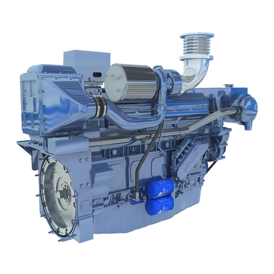
HOWO двигатель WD 615
Сообщение nekesha » 03 апр 2016, 17:05
Руководство по эксплуатации, техобслуживанию и ремонту двигателя WD 615

- Модификации моделей: WD 615
- Язык: Русский
Формат: PDF
Размер: 2,89 Мб
Скачать документацию двигателя WD 615
для распаковки архива используйте пароль — avtoproblem-net.ru

Ремонт двигателя WD615G 220
Ремонт двигателя WD615G 220
Китайская спецтехника очень востребована на территории России. Причины этого — приемлемая стоимость, достойное качество и доступность запасных частей для ремонта. Немаловажным обстоятельством является и то, что Китай производит комплектующие и силовые агрегаты, которые могут использоваться целым рядом категорий транспортных средств. К примеру, двигатель WD615G 220 устанавливают на фронтальных погрузчиках, автобусах, самосвалах и бульдозерах, произведенных в Китае.
Причины возникновения дефектов
Сегодня производители китайской тяжелой спецтехники выходят на передовые позиции в мире, вытесняя европейские и американские бренды. Хотя транспорт из США и Европы и славится своей надежностью и долговечностью, цена его часто запредельно высока. Качество техники из КНР с каждым годом растет, тем более что ведущие производители работают в связке с лидерами машиностроительной отрасли.
Невзирая на высокое качество материалов, применяемых для производства моторов, и отменное качество сборки, высокие нагрузки и не всегда корректная эксплуатация спецтехники приводит к сбоям в работе двигателя. Самыми частыми причинами называют:
- Нарушение графика технического обслуживания.
- Использование горючего низкого качества.
- Огрехи в эксплуатации.
- Частые перегревы.
- Попадание в мотор сторонних предметов.
- Чрезмерно загрязненная топливная и охлаждающая система.
- Выход из строя топливного насоса.
- Дефект турбокомпрессора.
Порядок устранения неисправностей
Ремонт двигателя начинают с проведения внешнего осмотра с составлением описи состояния комплектующих. Порядок диагностики следующий:
- Гильзо-поршневая группа.
- Шатун.
- Диаметр цилиндров.
- Коленвал.
- Диаметр шеек коленчатого вала.
- Герметичность головки блока цилиндров.
- Газораспределительная система.
- Диаметр шеек распределительного вала.
- Степень повреждения клапанов.
- Диаметр постелей блока цилиндров.
- Форсунки.
- Стартер.
- Генератор.
- Турбокомпрессор.
- Масляный насос.
- Водяная помпа.
После осмотра мастер оформляет так называемую дефектную ведомость и составляет перечень запасных частей, необходимых для проведения ремонтных работ.
После замены комплектующих двигатель собирают, ставят термопломбы и обкатывают на диагностическом стенде. Чтобы проверить эффективность проведенных мероприятий, мотор запускают и замеряют рабочие показатели — давление жидкостей, температуру нагрева, качество впрыска и прочие параметры.
Затем двигатель возвращается клиенту либо устанавливается на прежнее место. Обязательна выдача гарантии на ремонтные работы сроком не менее 6 месяцев.
Похожие статьи


РУКОВОДСТВО ПО ЭКСПЛУАТАЦИИ И ОБСЛУЖИВАНИЮ ДВИГАТЕЛЯ СЕРИИ WD615
Предлагаемая книга содержит все необходимые сведения о технических характеристиках, правилах эксплуатации и обслуживания двигателей серии WD615.
Двигатели WD615 производятся предприятиями в Китае по лицензии фирмы Steir.
Несмотря на то, что была сохранена конструкция дизельных двигателей оригинала(Steir) и, в целом, сохранена общая совокупность деталей, были улучшены параметры системы сгорания, выхлопа, охлаждения и смазки, зажигания, а также увеличена мощность для того, чтобы удовлетворить требования машиностроительного рынка.
Посмотреть и скачать электронную версию руководства можно по ссылке_______________
Наша компания предлагает к поставке под заказ ассортимент расходных материалов и запасных частей для судовых двигателей WD615C и WD618C.
Уточнить стоимость и срок поставки Вы можете заполнив простую форму обратной связи 
закажи профессиональный лендинг в megagroup.ru
")