- Обзор
- Характеристики
- Награды
- Галерея
- Поддержка
- Обзор
- Характеристики
- Награды
- Галерея
- Поддержка

Регистрация устройства поможет вам управлять его гарантией, получать техническую поддержку и отслеживать статус ремонта.
ASUS Footer
-
Contents
-
Table of Contents
-
Bookmarks
Quick Links
Related Manuals for Asus ROG STRIX Z370-E GAMING
Summary of Contents for Asus ROG STRIX Z370-E GAMING
-
Page 1
STRIX Z370-E GAMING… -
Page 2
Product warranty or service will not be extended if: (1) the product is repaired, modified or altered, unless such repair, modification of alteration is authorized in writing by ASUS; or (2) the serial number of the product is defaced or missing. -
Page 3: Table Of Contents
Contents Safety information …………………. vi About this guide ………………….vii ROG STRIX Z370-E GAMING specifications summary ……….. ix Package contents ………………… xiii Installation tools and components …………….. xiv Chapter 1: Product Introduction Motherboard overview …………….1-1 1.1.1 Before you proceed …………..1-1 1.1.2…
-
Page 4
3.6.11 USB Configuration …………..3-19 Monitor menu ………………. 3-20 Boot menu ………………..3-20 Tool menu ………………..3-22 3.9.1 ASUS EZ Flash 3 Utility …………3-22 3.9.2 Secure Erase …………….3-22 3.9.3 ASUS Overclocking Profile …………3-24 3.9.4 ASUS SPD Information …………. 3-24 3.9.5… -
Page 5
Rapid Storage Technology in UEFI BIOS ……4-2 ® 4.1.4 Intel Rapid Storage Technology Option ROM utility ….4-6 ® Creating a RAID driver disk…………..4-10 4.2.1 Creating a RAID driver disk in Windows ……… 4-10 ® Appendix Notices ……………………A-1 ASUS contact information ………………A-7… -
Page 6: Safety Information
Safety information Electrical safety • To prevent electrical shock hazard, disconnect the power cable from the electrical outlet before relocating the system. • When adding or removing devices to or from the system, ensure that the power cables for the devices are unplugged before the signal cables are connected. If possible, disconnect all power cables from the existing system before you add a device.
-
Page 7: About This Guide
Refer to the following sources for additional information and for product and software updates. ASUS website The ASUS website (www.asus.com) provides updated information on ASUS hardware and software products. Optional documentation Your product package may include optional documentation, such as warranty flyers, that may have been added by your dealer.
-
Page 8: Conventions Used In This Guide
Conventions used in this guide To ensure that you perform certain tasks properly, take note of the following symbols used throughout this manual. DANGER/WARNING: Information to prevent injury to yourself when trying to complete a task. CAUTION: Information to prevent damage to the components when trying to complete a task.
-
Page 9: Rog Strix Z370-E Gaming Specifications Summary
Supports AMD 3-Way CrossFireX™ Technology ® 1 x ASUS Wi-Fi module (Wi-Fi 802.11 a/b/g/n/ac and Bluetooth v4.2) 2 x USB3.1 Gen2 ports (1 x Type-A [red] and 1 x Type-C ports at back panel) 1 x DVI port 1 x HDMI port…
-
Page 10
Processors. Before using Intel Optane memory modules, ensure that you have ® updated your motherboard drivers and BIOS to the latest version from ASUS support website. ROG SupremeFX S1220A 8-Channel High Definition Audio CODEC — Supports up to 32-Bit/192kHz playback*… -
Page 11
ROG STRIX Z370-E GAMING specifications summary Intel I219-V Gigabit LAN- Dual interconnect between the integrated Media ® Access Controller (MAC) and physical layer (PHY) Anti-surge LANGuard ROG GameFirst Technology Wi-Fi 802.11 a/b/g/n/ac supports dual frequency band 2.4/5 GHz with Wireless &… -
Page 12
EZ Update Anti-virus software (OEM version) Operating Windows 10 64-bit ® system support Form factor ATX Form Factor, 12”x 9.6” (30.5cm x 24.4cm) Specifications are subject to change without notice. Please refer to the ASUS website for the latest specifications. -
Page 13: Package Contents
1 x RGB LED extension cable 1 x Addressable LED extension cable 1 x Thermal sensor cable 1 x I/O shield 1 x ASUS 2T2R dual band Wi-Fi moving antennas (Wi-Fi 802.11a/b/g/n/ac compliant) 1 x CPU Installation tool 1 x ROG cable label…
-
Page 14: Installation Tools And Components
Installation tools and components Intel 1151 CPU ® Intel 1151 compatible CPU Fan ® Phillips (cross) screwdriver SATA hard disk drive PC chassis 1 bag of screws DIMM Power supply unit SATA optical disc drive (optional) Graphics card The tools and components listed above are not included in the motherboard package.
-
Page 15: Chapter 1: Product Introduction
Chapter 1: Product Introduction Product Introduction Motherboard overview 1.1.1 Before you proceed Take note of the following precautions before you install motherboard components or change any motherboard settings. • Unplug the power cord from the wall socket before touching any component. • Before handling components, use a grounded wrist strap or touch a safely grounded object or a metal object, such as the power supply case, to avoid damaging them due to static electricity. • Hold components by the edges to avoid touching the ICs on them. • Whenever you uninstall any component, place it on a grounded antistatic pad or in the bag that came with the component. • Before you install or remove any component, ensure that the ATX power supply is switched off or the power cord is detached from the power supply. Failure to do so may cause severe damage to the motherboard, peripherals, or components. ASUS ROG STRIX Z370-E GAMING…
-
Page 16: Motherboard Layout
1.1.2 Motherboard layout 24.4cm(9.6in) CPU_OV RGB_HEADER2 CPU_FAN EATX12V M.2(WIFI) DIGI+ CHA_FAN1 CPU_OPT USB31G2_EC1 USB31G2_E2 3142 BOOT_DEVICE_LED VGA_LED DRAM_LED CPU_LED MOUNT PWR_LED LGA1151 HDMI USB1314 1442K LAN1_U31G1_56 CHA_FAN2 AUDIO AIO_PUMP PCIE_X1_1 2280 2260 2242 3142 ASM1480 ASM1480 ASM1480 ASM1480 ASM1480 M.2_2(SOCKET3) PCIE_X16/X8_1 PCIE SATA IRST…
-
Page 17: Layout Contents
9. USB 3.1 Gen1 connectors (20-1 pin U31G1_12,U31G1_34) 1-14 10. Intel Serial ATA 6 Gb/s connectors (7-pin SATA6G_12, SATA 6G_34, ® 1-12 SATA 6G_56) 11. Clear RTC RAM jumper (2-pin CLRTC) 12. System panel connector (20-3 pin PANEL) 1-17 13. USB 2.0 connectors (10-1 pin USB910, USB1112) 1-14 14. Addressable RGB header (4-1 pin ADD_HEADER) 1-21 15. TPM connector (14-1 pin TPM) 1-18 16. Serial port connector (10-1 pin COM) 1-18 17. Front panel audio connector (10-1 pin AAFP) 1-13 18. Thermal sensor cable connector (2-pin T_SENSOR) 1-19 19. CPU over voltage jumper (3-pin CPU_OV) 1-10 ASUS ROG STRIX Z370-E GAMING…
-
Page 18: Central Processing Unit (Cpu)
1.1.3 Central Processing Unit (CPU) The motherboard comes with a surface mount LGA1151 socket designed for the 8th Generation Intel Core™ processors. ® ® STRIX Z370-E GAMING ROG STRIX Z370-E GAMING CPU LGA1151 • Ensure that all power cables are unplugged before installing the CPU. • Upon purchase of the motherboard, ensure that the PnP cap is on the socket and the socket contacts are not bent. Contact your retailer immediately if the PnP cap is missing, or if you see any damage to the PnP cap/socket contacts/motherboard components. ASUS will shoulder the cost of repair only if the damage is shipment/ transit-related. • Keep the cap after installing the motherboard. ASUS will process Return Merchandise Authorization (RMA) requests only if the motherboard comes with the cap on the LGA1151 socket. • The product warranty does not cover damage to the socket contacts resulting from incorrect CPU installation/removal, or misplacement/loss/incorrect removal of the PnP cap. Chapter 1: Product Introduction…
-
Page 19: System Memory
1.1.4 System memory The motherboard comes with four DDR4 (Double Data Rate 4) Quad Inline Memory Modules (DIMM) slots. A DDR4 module is notched differently from a DDR, DDR2, or DDR3 module. DO NOT install a DDR, DDR2, or DDR3 memory module to the DDR4 slot. ® STRIX Z370-E GAMING ROG STRIX Z370-E GAMING 288-pin DDR4 DIMM sockets Recommended memory configurations ASUS ROG STRIX Z370-E GAMING…
-
Page 20: Memory Configurations
OS when you want to install 4 GB or more on the ® motherboard. c) For more details, refer to the Microsoft support site at http://support.microsoft. ® com/kb/929605/en-us. • The design of the DIMM fan may vary. Ensure that the DIMM fan fits to the motherboard • The default memory operation frequency is dependent on its Serial Presence Detect (SPD), which is the standard way of accessing information from a memory module. Under the default state, some memory modules for overclocking may operate at a lower frequency than the vendor-marked value. • For system stability, use a more efficient memory cooling system to support a full memory load (4 DIMMs) or overclocking condition. • Memory modules with memory frequency higher than 2133MHz and their corresponding timing or the loaded XMP profile is not the JEDEC memory standard. The stability and compatibility of the memory modules depend on the CPU’s capabilities and other installed devices. • Always install the DIMMS with the same CAS Latency. For an optimum compatibility, we recommend that you install memory modules of the same version or data code (D/C) from the same vendor. Check with the vendor to get the correct memory modules. • ASUS exclusively provides hyper DIMM support function. • Hyper DIMM support is subject to the physical characteristics of individual CPUs. Load the X.M.P. or D.O.C.P. settings in the BIOS for the hyper DIMM support. • Visit the ASUS website for the latest QVL. Chapter 1: Product Introduction…
-
Page 21: Expansion Slots
1.1.5 Expansion slots Unplug the power cord before adding or removing expansion cards. Failure to do so may cause you physical injury and damage motherboard components. PCIE_X1_1 PCIE_X16/X8_1 PCIE_X1_2 PCIE_X1_3 ® STRIX Z370-E GAMING PCIE_X8_2 PCIE_X1_4 PCIE_X4 Slot No. Slot Description PCIE_x1_1 slot PCIE_x16/x8_1 slot PCIE_x1_2 slot PCIE_x1_3 slot PCIE_x8_2 slot PCIE_x1_4 slot PCIE_x4 slot ASUS ROG STRIX Z370-E GAMING…
-
Page 22
PCI Express 3.0 operating mode VGA configuration PCIe_x16/x8_1 PCIe_x8_2 x16 (single VGA Single VGA/PCIe card recommended) Dual VGA/PCIe cards • We recommend that you provide sufficient power when running CrossFireX™ or SLI™ mode. • Connect a chassis fan to the motherboard connector labeled CHA_FAN1-2 when using multiple graphics cards for better thermal environment. PCI Express 3.0 operating mode Hyper M.2 X16 card configuration PCIe_x16/x8_1 PCIe_x8_2 2 Intel SSDs on CPU ® x4+x4 support 3 Intel SSDs on CPU ® x8+x4+x4 support •… -
Page 23: Jumpers And Holes
1.1.6 Jumpers and holes Clear RTC RAM jumper (2-pin CLRTC) This jumper allows you to clear the Real Time Clock (RTC) RAM in CMOS. You can clear the CMOS memory of date, time, and system setup parameters by erasing the CMOS RTC RAM data. The onboard button cell battery powers the RAM data in CMOS, which include system setup information such as system passwords. CLRTC ® STRIX Z370-E GAMING PIN 1 ROG STRIX Z370-E GAMING Clear RTC RAM To erase the RTC RAM: Turn OFF the computer and unplug the power cord. Short-circuit pin 1-2 with a metal object or jumper cap for about 5-10 seconds. Plug the power cord and turn ON the computer. Hold down the <Delete> key during the boot process and enter BIOS setup to re-enter data. Except when clearing the RTC RAM, never remove the cap on CLRTC jumper default position. Removing the cap will cause system boot failure! • If the steps above do not help, remove the onboard battery and move the jumper again to clear the CMOS RTC RAM data. After the CMOS clearance, reinstall the battery.
-
Page 24
® STRIX Z370-E GAMING ROG STRIX Z370-E GAMING CPU_OV setting 3D Mount Secure 3D printed parts to these 3D Mount holes for a personalized motherboard. 3D Mount 3D Mount ® STRIX Z370-E GAMING 3D Mount ROG STRIX Z370-E GAMING 3D Printing Mount • Download 3D source files at http://www.asus.com. • Use the bundled 3D Mount screws to install the 3D printed parts. Chapter 1: Product Introduction 1-10… -
Page 25: Onboard Leds
BOOT (YELLOW GREEN) VGA (WHITE) DRAM (YELLOW) CPU (RED) ® STRIX Z370-E GAMING ROG STRIX Z370-E GAMING CPU/DRAM/BOOT_DEVICE/VGA LED Standby Power LED The motherboard comes with a standby power LED. The LED lights up to indicate that the system is ON, in sleep mode, or in soft-off mode. This is a reminder that you should shut down the system and unplug the power cable before removing or plugging in any motherboard component. The illustration below shows the location of the onboard LED. PWR_LED ® STRIX Z370-E GAMING ROG STRIX Z370-E GAMING PWR_LED ASUS ROG STRIX Z370-E GAMING 1-11…
-
Page 26: Internal Connectors
® RSATA_TXP5 RSATA_TXP6 STRIX Z370-E GAMING RSATA_TXN5 RSATA_TXN6 RSATA_RXN5 RSATA_RXN6 RSATA_RXP5 RSATA_RXP6 ROG STRIX Z370-E GAMING Intel SATA 6 Gb/s connectors ® • These connectors are set to [AHCI] by default. If you intend to create a Serial ATA RAID set using these connectors, set the SATA Mode item in the BIOS to [Intel RST Premium With Intel Optane System Acceleration (RAID)]. • Before creating a RAID set, refer to the manual bundled in the motherboard support DVD. Chapter 1: Product Introduction…
-
Page 27
USB 3.1 Gen2 front panel connector (U31G2_E3) This connector allows you to connect a USB 3.1 Gen2 module for additional USB 3.1 Gen2 ports. The latest USB 3.1 Gen2 connectivity provides data transfer speeds of up to 10 Gbps. The next-generation standard is completely backward-compatible with your existing USB devices. U31G2_E3 VBUS SBU2 TX2+ SBU1 TX2- VBUS RX2+ RX1- RX2- RX1+ TX1- TX1+ ® VBUS STRIX Z370-E GAMING ROG STRIX Z370-E GAMING USB 3.1 Gen 2 front panel connector ASUS ROG STRIX Z370-E GAMING 1-13… -
Page 28
Gen1 front or rear panel ports. With an installed USB 3.1 Gen1 module, you can enjoy all the benefits of USB 3.1 Gen1 including faster data transfer speeds of up to 5 Gb/s, faster charging time for USB-chargeable devices, optimized power efficiency, and backward compatibility with USB 2.0. U31G1_12 U31G1_34 PIN 1 PIN 1 ® STRIX Z370-E GAMING ROG STRIX Z370-E GAMING USB 3.1 Gen 1 connectors The USB 3.1 Gen1 module is purchased separately. USB 2.0 connectors (10-1 pin USB910, USB1112) These connectors are for USB 2.0 ports. Connect the USB module cable to these connectors, then install the module to a slot opening at the back of the system chassis. This USB connector complies with USB 2.0 specification that supports up to 480 Mb/s connection speed. USB910 USB1112 ® STRIX Z370-E GAMING… -
Page 29
• Ensure that the CPU fan cable is securely installed to the CPU fan connector. CPU_FAN CHA_FAN1 CPU_OPT CHA FAN PWM CHA FAN IN CHA FAN PWR CHA_FAN2 AIO_PUMP EXT_FAN M.2_FAN ® STRIX Z370-E GAMING ROG STRIX Z370-E GAMING Fan connectors • The CPU_FAN connector supports the CPU fan of maximum 1A (12 W) fan power. • The EXT_FAN connector supports 2 of 5 thermal sensor sources. • Connect the fan of your water cooling kit to the AIO_PUMP connector. ASUS ROG STRIX Z370-E GAMING 1-15… -
Page 30
-5 Volts PIN 1 +5 Volts +5 Volts PSON# +3 Volts -12 Volts +3 Volts +3 Volts PIN 1 ® STRIX Z370-E GAMING ROG STRIX Z370-E GAMING ATX power connectors • For a fully configured system, we recommend that you use a power supply unit (PSU) that complies with ATX 12 V Specification 2.0 (or later version) and provides a minimum power of 350 W. • DO NOT forget to connect the 8-pin EATX12V power plug. Otherwise, the system will not boot. • We recommend that you use a PSU with a higher power output when configuring a system with more power-consuming devices. The system may become unstable or may not boot up if the power is inadequate. -
Page 31: System Panel Connector
SPEAKER CHASSIS PANEL PIN 1 ® STRIX Z370-E GAMING HDD_LED RESET PLED ROG STRIX Z370-E GAMING System panel connector • System power LED (2-pin or 3-1 pin PLED) The 2-pin or 3-1 pin connector is for the system power LED. Connect the chassis power LED cable to this connector. The system power LED lights up when you turn on the system power, and blinks when the system is in sleep mode. • Hard disk drive activity LED (2-pin HDD_LED) This 2-pin connector is for the HDD Activity LED. Connect the HDD Activity LED cable to this connector. The HDD LED lights up or flashes when data is read from or written…
-
Page 32
PIN 1 ® STRIX Z370-E GAMING ROG STRIX Z370-E GAMING TPM connector The TPM module is purchased separately. Serial port connector (10-1 pin COM) This connector is for a serial (COM) port. Connect the serial port module cable to this connector, then install the module to a slot opening at the back of the system chassis. ® STRIX Z370-E GAMING PIN 1 ROG STRIX Z370-E GAMING Serial port connector The COM module is purchased separately. Chapter 1: Product Introduction 1-18… -
Page 33
M.2 sockets (M.2_1; M.2_2) These sockets allow you to install M.2 SSD modules. M.2_2(SOCKET3) 2280 2260 2242 M.2_1(SOCKET3) ® STRIX Z370-E GAMING 2280 2260 2242 ROG STRIX Z370-E GAMING M.2 sockets • M.2_1 socket supports PCIe 3.0 x4 and SATA mode M Key design and type 2242 / 2260 / 2280 PCIe and SATA storage devices. • M.2_2 socket supports PCIe 3.0 x4 M Key design and type 2242 / 2260 / 2280 PCIe storage devices. • These sockets support IRST (Intel Rapid Storage Technology). ® The M.2 SSD module is purchased separately. Thermal sensor connector (2-pin T_SENSOR) This connector is for the thermistor cable that monitors the temperature of the devices and the critical components inside the motherboard. Connect the thermistor cable… -
Page 34
RGB headers (4-pin RGB_HEADER1-2) These connectors are for RGB LED strips. RGB_HEADER2 PIN 1 +12V G R B RGB_HEADER1 PIN 1 +12V G R B ® STRIX Z370-E GAMING ROG STRIX Z370-E GAMING RGB_HEADER connectors The RGB header supports 5050 RGB multi-color LED strips (12V/G/R/B), with a maximum power rating of 2A (12V), and no longer than 2 m. Before you install or remove any component, ensure that the ATX power supply is switched off or the power cord is detached from the power supply. Failure to do so may cause severe damage to the motherboard, peripherals, or components. • Actual lighting and color will vary with LED strip. • If your LED strip does not light up, check if the RGB LED extension cable and the RGB LED strip is connected in the correct orientation, and the 12V connector is aligned with the 12V header on the motherboard. -
Page 35
Addressable RGB header (4-1 pin ADD_HEADER) This connector is for individually addressable RGB WS2812B LED strips with embedded WS2811LED driver ICs. ® STRIX Z370-E GAMING ROG STRIX Z370-E GAMING EXTREME ADD header The addressable RGB header supports WS2812B addressable RGB LED strips (5V/Data/ Ground), with a maximum power rating of 3A (5V) and a maximum of 60 LEDs. Before you install or remove any component, ensure that the ATX power supply is switched off or the power cord is detached from the power supply. Failure to do so may cause severe damage to the motherboard, peripherals, or components. • Actual lighting and color will vary with LED strip. • If your LED strip does not light up, check if the addressable RGB LED strip is connected in the correct orientation, and the 5V connector is aligned with the 5V header on the motherboard. • The addressable RGB LED strip will only light up under the operating system. • The addressable RGB LED strip is purchased separately. ASUS ROG STRIX Z370-E GAMING 1-21… -
Page 36
Chapter 1: Product Introduction 1-22… -
Page 37: Chapter 2: Basic Installation
2.1.1 Motherboard installation Install the ASUS Q-Shield to the chassis rear I/O panel. Place the motherboard into the chassis, ensuring that its rear I/O ports are aligned to the chassis’ rear I/O panel.
-
Page 38
Place nine (9) screws into the holes indicated by circles to secure the motherboard to the chassis. ® STRIX Z370-E GAMING DO NOT overtighten the screws! Doing so can damage the motherboard. Chapter 2: Basic Installation… -
Page 39: Cpu Installation
Ensure that you install the correct CPU designed for LGA1151 socket only. DO NOT install a CPU designed for LGA1155 and LGA1156 sockets on the LGA1151 socket. Top of CPU Bottom of CPU Bottom of CPU ASUS ROG STRIX Z370-E GAMING…
-
Page 40
Top of CPU • The CPU Installation Tool is only compatible on ASUS motherboards with a Intel ® LGA1151 socket. • Ensure that the CPU is firmly clicked into place before installing it onto the CPU socket on the motherboard. • Use the CPU Installation Tool for installing the CPU only. DO NOT damage or bend the CPU Installation Tool. • Always firmly hold both sides of the CPU Installation Tool when installing, removing, or picking up the CPU Installation Tool. • Ensure to use a soft stable surface when installing the CPU to the CPU Installation Tool to prevent CPU damage. • ASUS will not cover damages resulting from incorrect CPU installation/removal, incorrect CPU orientation/placement, or other damages resulting from negligence by the user. -
Page 41: Cpu Heatsink And Fan Assembly Installation
2.1.3 CPU heatsink and fan assembly installation Apply the Thermal Interface Material to the CPU heatsink and CPU before you install the heatsink and fan, if necessary. To install the CPU heatsink and fan assembly ASUS ROG STRIX Z370-E GAMING…
-
Page 42
To uninstall the CPU heatsink and fan assembly Chapter 2: Basic Installation… -
Page 43: Dimm Installation
2.1.4 DIMM installation To remove a DIMM ASUS ROG STRIX Z370-E GAMING…
-
Page 44: Atx Power Connection
2.1.5 ATX power connection Ensure to connect the 8-pin power plug. Chapter 2: Basic Installation…
-
Page 45: Sata Device Connection
2.1.6 SATA device connection ASUS ROG STRIX Z370-E GAMING…
-
Page 46: Front I/O Connector
2.1.7 Front I/O connector To install USB 3.1 Gen2 connector To install front panel connector USB 3.1 Gen2 This connector will only fit in one orientation. Push the connector until it clicks into place. To install USB 3.1 Gen1 connector To install USB 2.0 connector USB 3.1 Gen1 USB 2.0 To install front panel audio connector AAFP…
-
Page 47: Expansion Card Installation
2.1.8 Expansion card installation To install PCIe x16 cards To install PCIe x1 cards ASUS ROG STRIX Z370-E GAMING 2-11…
-
Page 48
To install HYPER M.2 x4 card The SSD card is purchased separately. Chapter 2: Basic Installation 2-12… -
Page 49: M.2 Installation
2.1.9 M.2 installation • Please remove the plastic film from the thermal pad before use. • Use the bundled M.2 screws to secure the M.2. ASUS ROG STRIX Z370-E GAMING 2-13…
-
Page 50
Supported M.2 type varies per motherboard. Use the bundled M.2 screws to secure the M.2. Chapter 2: Basic Installation 2-14… -
Page 51: Wi-Fi Antenna Installation
2.1.10 Wi-Fi antenna installation Installing the ASUS 2×2 dual band W-Fi antenna Connect the bundled ASUS 2×2 dual band Wi-Fi antenna connector to the Wi-Fi ports at the back of the chassis. • Ensure that the ASUS 2×2 dual band Wi-Fi antenna is securely installed to the Wi-Fi ports. • Ensure that the antenna is at least 20 cm away from all persons. The illustration above is for reference only. The I/O port layout may vary with models, but the Wi-Fi antenna installation procedure is the same for all models. ASUS ROG STRIX Z370-E GAMING…
-
Page 52: Fan Holder Installation
2.1.11 Fan holder installation To install the Fan holder and fan ® STRIX Z370-E GAMING When using high performance settings whilst overclocking, ensure to install the fan holder for additional fan(s). • You may install 40mm x 40mm fans or 50mm x 50mm fans. • Fans are purchased separately. Chapter 2: Basic Installation 2-16…
-
Page 53: Motherboard Rear And Audio Connections
DVI-D port USB 3.1 Gen1 ports USB 2.0 ports Optical S/PDIF Out port Intel LAN port (LAN1)** Audio I/O ports*** ® USB 3.1 Gen2 Type-C port EC1 * S upport for the Bluetooth specification depends on the Windows version. ® ** and *** : R efer to the tables on the next page for LAN port LEDs and audio port definitions. • The plugged USB 3.1 Gen1 device may run on xHCI mode or EHCI mode, depending on the operating system’s setting. • USB 3.1 Gen1 devices can only be used as data storage only. • We strongly recommend that you connect USB 3.1 Gen1 devices to USB 3.1 Gen1 ports for faster and better performance for your USB 3.1 Gen1 devices. ASUS ROG STRIX Z370-E GAMING 2-17…
-
Page 54
** LAN ports LED indications Activity Link LED Speed LED Status Description Status Description ACT/LINK SPEED No link 10 Mbps connection Orange Linked Orange 100 Mbps connection Orange (Blinking) Data activity Green 1 Gbps connection Orange (Blinking Ready to wake up LAN port then steady) from S5 mode You can disable the LAN controllers in BIOS. Due to hardware design, the LAN1 port’s… -
Page 55: Audio I/O Connections
2.2.2 Audio I/O connections Audio I/O ports Connect to Headphone and Mic Connect to Stereo Speakers Connect to 2 channel Speakers ASUS ROG STRIX Z370-E GAMING 2-19…
-
Page 56
Connect to 4 channel Speakers Connect to 6 channel Speakers Chapter 2: Basic Installation 2-20… -
Page 57: Starting Up For The First Time
If you do not see anything within 30 seconds from the time you turned on the power, the system may have failed a power-on test. Check the jumper settings and connections or call your retailer for assistance. ASUS ROG STRIX Z370-E GAMING 2-21…
-
Page 58: Turning Off The Computer
BIOS Beep Description One short beep VGA detected Quick boot set to disabled No keyboard detected One continuous beep followed by two No memory detected short beeps then a pause (repeated) One continuous beep followed by three No VGA detected short beeps One continuous beep followed by four Hardware component failure…
-
Page 59: Chapter 3: Bios Setup
BIOS Setup Knowing BIOS The new ASUS UEFI BIOS is a Unified Extensible Interface that complies with UEFI architecture, offering a user-friendly interface that goes beyond the traditional keyboard- only BIOS controls to enable a more flexible and convenient mouse input. You can easily navigate the new UEFI BIOS with the same smoothness as your operating system.
-
Page 60: Bios Setup Program
RTC RAM via the Clear CMOS jumper. • The BIOS setup program does not support the Bluetooth devices. Please visit ASUS website for the detailed BIOS content manual. BIOS menu screen The BIOS Setup program can be used under two modes: EZ Mode and Advanced Mode.
-
Page 61: Ez Mode
Click to go to Advanced mode Loads optimized Search on the FAQ default settings Click to display boot devices Selects the boot device priority The boot device options vary depending on the devices you installed to the system. ASUS ROG STRIX Z370-E GAMING…
-
Page 62: Advanced Mode
3.2.2 Advanced Mode The Advanced Mode provides advanced options for experienced end-users to configure the BIOS settings. The figure below shows an example of the Advanced Mode. Refer to the following sections for the detailed configurations. To switch from EZ Mode to Advanced Mode, click Advanced Mode(F7) or press the <F7> hotkey.
-
Page 63: Menu Bar
This button above the menu bar allows you to view and tweak the overclocking settings of your system. It also allows you to change the motherboard’s SATA mode from AHCI to RAID mode. Refer to section 3.2.4 EZ Tuning Wizard for more information. ASUS ROG STRIX Z370-E GAMING…
-
Page 64: Hot Keys
Move your mouse over this button to show a QR code, scan this QR code on your mobile device to connect to the BIOS FAQ web page of the ASUS support website. You can also scan the following QR code: Hot keys This button above the menu bar contains the navigation keys for the BIOS setup program.
-
Page 65: Qfan Control
PWM Mode Select a profile to Click to apply the fan setting apply to your fans Click to undo the Click to go back to main menu changes Select to manually configure your fans ASUS ROG STRIX Z370-E GAMING…
-
Page 66
Configuring fans manually Select Manual from the list of profiles to manually configure your fans’ operating speed. Speed points Select to manually configure your fans To configure your fans: Select the fan that you want to configure and to view its current status. Click and drag the speed points to adjust the fans’… -
Page 67: Ez Tuning Wizard
To start OC Tuning: Press <F11> on your keyboard or click from the BIOS screen to open EZ Tuning Wizard screen. Click OC then click Next. Select a PC scenario Daily Computing or Gaming/Media Editing, then click Next. ASUS ROG STRIX Z370-E GAMING…
-
Page 68: Creating Raid
Select a Main Cooling System BOX cooler, Tower cooler, Water cooler, or I’m not sure, then click Next. After selecting the Main Cooling System, click Next then click Yes to start the OC Tuning. Creating RAID To create RAID: Press <F11> on your keyboard or click from the BIOS screen to open EZ Tuning Wizard screen.
-
Page 69
After selecting the type of RAID, click Next then click Yes to continue the RAID setup. After the RAID setup is done, click Yes to exit the setup then click OK to reset your system. ASUS ROG STRIX Z370-E GAMING 3-11… -
Page 70: My Favorites
My Favorites My Favorites is your personal space where you can easily save and access your favorite BIOS items. My Favorites comes with several performance, power saving, and fast boot related items by default. You can personalize this screen by adding or removing items. Chapter 3: BIOS Setup 3-12…
-
Page 71
Configuration items such as Memory SPD Information, system time and date. Click Exit (ESC) or press <Esc> key to close Setup Tree Map screen. Go to My Favorites menu to view the saved BIOS items. ASUS ROG STRIX Z370-E GAMING 3-13… -
Page 72: Main Menu
Main menu The Main menu screen appears when you enter the Advanced Mode of the BIOS Setup program. The Main menu provides you an overview of the basic system information, and allows you to set the system date, time, language, and security settings. Security The Security menu items allow you to change the system security settings.
-
Page 73
Configuration options: [Auto] [Disabled] [Enabled] Turbo Mode Allows you to enable your processor cores to run faster than the base operating frequency when it is below power, current and specification limit. Configuration options: [Disabled] [Enabled] ASUS ROG STRIX Z370-E GAMING 3-15… -
Page 74: Advanced Menu
Advanced menu The Advanced menu items allow you to change the settings for the CPU and other system devices. Be cautious when changing the settings of the Advanced menu items. Incorrect field values can cause the system to malfunction. 3.6.1 Platform Misc Configuration The items in this menu allow you to change the ASPM for PCH and SA PCI Express.
-
Page 75: System Agent (Sa) Configuration
SMART Self Test SMART (Self-Monitoring, Analysis and Reporting Technology) is a monitoring system that shows a warning message during POST (Power-on Self Test) when an error occurs in the hard disks. Configuration options: [On] [Off] ASUS ROG STRIX Z370-E GAMING 3-17…
-
Page 76: Pch-Fw Configuration
SATA6G_1(Charcoal Black) — SATA6G_6(Charcoal Black) SATA6G_1(Charcoal Black) — SATA6G_6(Charcoal Black) This item allows you to enable or disable the selected SATA port. Configuration options: [Disabled] [Enabled] Hot Plug These items appears only when the SATA Mode Selection is set to [AHCI] and allows you to enable or disable SATA Hot Plug Support.
-
Page 77: Apm Configuration
None. USB Single Port Control This item allows you to enable or disable the individual USB ports. Refer to section 1.1.2 Motherboard layout for the location of the USB ports. ASUS ROG STRIX Z370-E GAMING 3-19…
-
Page 78: Monitor Menu
Monitor menu The Monitor menu displays the system temperature/power status, and allows you to change the fan settings. Qfan Configuration Qfan Tuning Click this item to automatically detect the lowest speed and configure the minimum duty cycle for each fan. Boot menu The Boot menu items allow you to change the system boot options.
-
Page 79: Secure Boot
OS in Safe Mode, press <F8> after POST (Windows 8 not supported). • To select the boot device during system startup, press <F8> when the ASUS Logo appears. Boot Override These items displays the available devices. The number of device items that appears on the screen depends on the number of devices installed in the system.
-
Page 80: Tool Menu
3.9.1 ASUS EZ Flash 3 Utility This item allows you to run ASUS EZ Flash 3. When you press <Enter>, a confirmation message appears. Use the left/right arrow key to select between [Yes] or [No], then press <Enter> to confirm your choice.
-
Page 81
Locked. SSDs might be locked if the Secure Erase process is either incomplete or was stopped. This may be due to a third party software that uses a different password defined by ASUS. You have to unlock the SSD in the software before proceeding with Secure Erase. -
Page 82: Asus Overclocking Profile
This item displays the information about the graphics card installed in your system. GPU Post This item displays the information and recommended configuration for the PCIE slots that the graphics card is installed in your system. This feature is only supported on selected ASUS graphics cards. Chapter 3: BIOS Setup 3-24…
-
Page 83: Exit Menu
® ASUS EZ Flash 3: Updates the BIOS using a USB flash drive. ASUS CrashFree BIOS 3: Restores the BIOS using the motherboard support DVD or a USB flash drive when the BIOS file fails or gets corrupted. 3.11.1…
-
Page 84: Asus Ez Flash 3
3.11.2 ASUS EZ Flash 3 ASUS EZ Flash 3 allows you to download and update to the latest BIOS through the Internet without having to use a bootable floppy disk or an OS-based utility. Updating through the Internet varies per region and Internet conditions. Check your local Internet connection before updating through the Internet.
-
Page 85
To update the BIOS via Internet: Enter the Advanced Mode of the BIOS setup program. Go to the Tool menu to select ASUS EZ Flash Utility and press <Enter>. Select via Internet. Press the Left/Right arrow keys to select an Internet connection method, and then press <Enter>. -
Page 86: Asus Crashfree Bios 3
The BIOS file in the motherboard support DVD may be older than the BIOS file published on the ASUS official website. If you want to use the newer BIOS file, download the file at https://www.asus.com/support/ and save it to a USB flash drive.
-
Page 87: Chapter 4: Raid Support
With the RAID 10 configuration you get all the benefits of both RAID 0 and RAID 1 configurations. Use four new hard disk drives or use an existing drive and three new drives for this setup. ASUS ROG STRIX Z370-E GAMING…
-
Page 88: Installing Serial Ata Hard Disks
4.1.2 Installing Serial ATA hard disks The motherboard supports Serial ATA hard disk drives. For optimal performance, install identical drives of the same model and capacity when creating a disk array. To install the SATA hard disks for a RAID configuration: Install the SATA hard disks into the drive bays. Connect the SATA signal cables. Connect a SATA power cable to the power connector on each drive.
-
Page 89
When the RAID Level item is selected, press <Enter> to select the RAID level to create, and then press <Enter>. Under Select Disks, press <Enter> and select X for the disks you want to include in the RAID set. ASUS ROG STRIX Z370-E GAMING… -
Page 90
When the Strip Size item is selected, press <Enter> to select strip size for the RAID array (for RAID 0, 10 and 5 only), and then press <Enter>. The available strip size values range from 4 KB to 128 KB. The following are typical values: RAID 0: 128 KB RAID 10: 64 KB RAID 5: 64 KB… -
Page 91
<Enter>. The following screen appears: When the Delete item is selected, press <Enter>, then select Yes to delete the RAID volume and return to the Intel Rapid Storage Technology menu, or select No to ® cancel. ASUS ROG STRIX Z370-E GAMING… -
Page 92: Intel ® Rapid Storage Technology Option Rom Utility
4.1.4 Intel Rapid Storage Technology Option ROM utility ® To enter the Intel Rapid Storage Technology Option ROM utility: ® Enter the BIOS Setup during POST. Go to the Advanced menu > PCH Storage Configuration, then press <Enter>. Set the SATA Controller Mode Selection item to [Intel RST Premium With Intel Optane System Acceleration (RAID)]. Go to the Boot menu > CSM (Compatibility Support Module) > Launch CSM, then set the item to [Enabled].
-
Page 93
Size Status ST3160812AS 9LS0HJA4 149.0GB Non-RAID Disk ST3160812AS 9LS0F4HL 149.0GB Non-RAID Disk ST3160812AS 3LS0JYL8 149.0GB Non-RAID Disk ST3160812AS 9LS0BJ5H 149.0GB Non-RAID Disk Select 2 to 6 to use in creating the volume. [↑↓]-Prev/Next [SPACE]-SelectDisk [ENTER]-Done ASUS ROG STRIX Z370-E GAMING… -
Page 94
Use the up/down arrow key to select a drive, and then press <Space> to select. A small triangle marks the selected drive. Press <Enter> after completing your selection. Use the up/down arrow key to select the strip size for the RAID array (for RAID 0, 10 and 5 only),and then press <Enter>. -
Page 95
(This does not apply to Recovery volumes) Are you sure you want to delete “Volume0”? (Y/N): Press <Y> to delete the RAID set and return to the utility main menu, or press <N> to return to the DELETE VOLUME menu. ASUS ROG STRIX Z370-E GAMING… -
Page 96: Creating A Raid Driver Disk
Exiting the Intel Rapid Storage Technology Option ROM utility ® To exit the utility: From the utility main menu, select 5. Exit, and then press <Enter>. The following warning message appears: [CONFIRM EXIT] Are you sure you want to exit? (Y/N): Press <Y> to exit or press <N> to return to the utility main menu. 4.2 Creating a RAID driver disk 4.2.1…
-
Page 97: Appendix
Consult the dealer or an experienced radio/TV technician for help. The use of shielded cables for connection of the monitor to the graphics card is required to assure compliance with FCC regulations. Changes or modifications to this unit not expressly approved by the party responsible for compliance could void the user’s authority to operate this equipment. ASUS ROG STRIX Z370-E GAMING…
-
Page 98
Compliance Statement of Innovation, Science and Economic Development Canada (ISED) This Class B digital apparatus complies with Canadian ICES-003, RSS-210, and CAN ICES- 3(B)/NMB-3(B). This device complies with Industry Canada license exempt RSS standard(s). Operation is subject to the following two conditions: (1) this device may not cause interference, and (2) this device must accept any interference, including interference that may cause undesired operation of the device. -
Page 99
ASUS Recycling/Takeback Services ASUS recycling and takeback programs come from our commitment to the highest standards for protecting our environment. We believe in providing solutions for you to be able to responsibly recycle our products, batteries, other components as well as the packaging materials. -
Page 100
FCC Bluetooth Wireless Compliance The antenna used with this transmitter must not be co-located or operated in conjunction with any other antenna or transmitter subject to the conditions of the FCC Grant. Bluetooth Industry Canada Statement This Class B device meets all requirements of the Canadian interference-causing equipment regulations. -
Page 101
2014/53/EU. Cijeli di: https://www.asus.com/support/ tekst EU izjave o sukladnosti dostupan je na https://www.asus.com/support/ WiFi yang Beroperasi pada 5150-5350 MHz akan terbatas untuk penggunaan WiFi koji radi na opsegu frekvencija 5150-5350 MHz bit će ograničen na… -
Page 102
ASUSTek Computer Inc. tukaj izjavlja, da je ta naprava skladna s temeljnimi zahtevami in drugimi relevantnimii določili Direktive 2014/53/EU. Polno besedilo izjave EU o skladnosti je na voljo na https://www.asus.com/support/ WiFi, ki deluje v pasovnem območju 5150–5350 MHz, mora biti v državah, navedenih v spodnjem seznamu, omejen na notranjo uporabo: Declaración de conformidad simplificada para la UE… -
Page 103: Asus Contact Information
+1-510-739-3777 +1-510-608-4555 Web site http://www.asus.com/us/ Technical Support Support fax +1-812-284-0883 Telephone +1-812-282-2787 Online support http://qr.asus.com/techserv ASUS COMPUTER GmbH (Germany and Austria) Address Harkort Str. 21-23, 40880 Ratingen, Germany +49-2102-959931 Web site http://www.asus.com/de Online contact http://eu-rma.asus.com/sales Technical Support Telephone +49-2102-5789555 Support Fax…
-
Page 104: Declaration Of Conformity
CA 94539. Phone/Fax No: (510)739-3777/(510)608-4555 hereby declares that the product Product Name : Motherboard Model Number : ROG STRIX Z370-E GAMING Conforms to the following specifications: FCC Part 15, Subpart B, Unintentional Radiators Supplementary Information: This device complies with part 15 of the FCC Rules. Operation is subject to the…
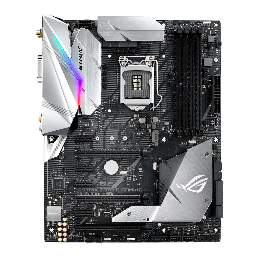
Материнская плата ASUS STRIX Z370-E GAMING
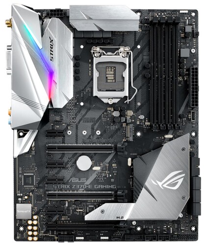
LGA 1151-v2, Intel Z370, 4xDDR4-4000 МГц, 3xPCI-Ex16, аудио 7.1, Standard-ATX
подробнее

8
Код товара: 1171949
-
Драйверы
52
-
Инструкции по эксплуатации
2
Языки:

ASUS ROG STRIX Z370-E GAMING инструкция по эксплуатации
(104 страницы)
- Языки:Английский
-
Тип:
PDF -
Размер:
8.76 MB -
Описание:
ROG STRIX Z370-E GAMING User’s Manual(English)
Просмотр

ASUS ROG STRIX Z370-E GAMING инструкция по эксплуатации
(105 страниц)
- Языки:Французский
-
Тип:
PDF -
Размер:
7.56 MB -
Описание:
ROG STRIX Z370-E GAMING User’s Manual(French)
Просмотр
На NoDevice можно скачать инструкцию по эксплуатации для ASUS ROG STRIX Z370-E GAMING. Руководство пользователя необходимо для ознакомления с правилами установки и эксплуатации ASUS ROG STRIX Z370-E GAMING. Инструкции по использованию помогут правильно настроить ASUS ROG STRIX Z370-E GAMING, исправить ошибки и выявить неполадки.
Посмотреть инструкция для Asus ROG STRIX Z370-E Gaming бесплатно. Руководство относится к категории материнские платы, 1 человек(а) дали ему среднюю оценку 8. Руководство доступно на следующих языках: английский. У вас есть вопрос о Asus ROG STRIX Z370-E Gaming или вам нужна помощь? Задайте свой вопрос здесь
- Safety information
- About this guide
- ROG STRIX Z370-E GAMING specifications summary
- Package contents
- Installation tools and components
- Chapter 1: Product Introduction
- Chapter 2: Basic Installation
- Chapter 3: BIOS Setup
- Chapter 4: RAID Support
- Appendix
Главная
| Asus | |
| ROG STRIX Z370-E Gaming | 90MB0V40-M0EAY0 | |
| материнская плата | |
| 4712900854961, 0889349854969 | |
| английский | |
| Руководство пользователя (PDF) |
Память
| Поддерживаемые типы памяти | DDR4-SDRAM |
| Тип слотов памяти | DIMM |
| Количество слотов памяти | 4 |
| Каналы памяти | Dual-channel |
| Error-correcting code (ECC) | Нет |
| Поддерживаемые частоты памяти | 2133,4000 MHz |
| Максимальная внутренняя память | 64 GB |
| Небуферизованная память | Да |
| без функции коррекции ошибок | Да |
Контроллеры хранения данных
| Поддерживаемые типы накопителей | HDD & SSD |
| Поддерживаемые интерфейсы носителя | M.2, SATA III |
| Уровни RAID | 0, 1,5, 10 |
Особые свойства процессора
| экстремальный профиль памяти Intel | Да |
| Intel® Optane™ Memory Ready | Да |
Свойства
| Поддерживаемые операционные системы Windows | Да |
| Комплектующие для | ПК |
| Семейство чипсета материнской платы | Intel |
| Чипсет материнской платы | Intel® Z370 |
| Формат материнской платы | ATX |
| Выходные звуковые каналы | 7.1 канала |
| Тип охлаждения | Пассивный |
| Мониторинг состояния ПК | CPU, FAN, Power supply, Temperature, Voltage |
| Тип источника питания | ATX |
Процессор
| Производитель процессора | Intel |
| Совместимые серии процессоров | Intel Core i3, Intel Core i5, Intel Core i7 |
| Максимальное число процессоров для SMP | 1 |
| Сокет процессора | LGA 1151 (разъем H4) |
| Поддерживаемые сокеты процессоров | LGA 1151 (разъем H4) |
Графический адаптер
| Семейство графического адаптера | Intel |
| Поддержка выделеной видео карты | Да |
| Поддержка технологии параллельной обработки | 2-Way CrossFireX, 2-Way SLI, 3-Way CrossFireX |
Внутренние порты
| Разъемы USB 2.0 | 2 |
| Разъемы USB 3.2 Gen 2 (3.1 Gen 2) | 0 |
| Разъемы USB 3.2 Gen 1 (3.1 Gen 1) | 2 |
| Число коннекторов SATA | 6 |
| Разъем питания ATX (24-конт.) | Да |
| Разъем вентилятора центрального процессора | Да |
| Аудиоразъем передней панели | Да |
| Разъем передней панели | Да |
| Количество параллельных разъемов ATA (PATA) | 0 |
| Количество разъемов SATA II | 0 |
| Количество разъемов SATA III | 6 |
| Количество COM-разъёмов | 1 |
| Количество разъемов вентилятора корпуса | 2 |
| EPS разъем питания (8-конт) | Да |
BIOS
| Тип BIOS | UEFI |
| Размер памяти BIOS | 16 Mbit |
| Версия ACPI | 6.0 |
Порты на задней панели
| Количество портов USB 2.0 | 0 |
| Количество портов USB 3.2 Gen 1 (3.1 Gen 1) Type-С | 0 |
| Количество портов USB 3.2 Gen 1 (3.1 Gen 1) Type-A | 2 |
| Количество портов USB 3.2 Gen 2 (3.1 Gen 2) Type-A | 1 |
| Количество портов Ethernet LAN ( RJ-45) | 1 |
| Количество портов USB 3.2 Gen 2 (3.1 Gen 2) Type-С | 1 |
| Количество портов eSATA | 0 |
| Линейный вход микрофона | Да |
| Линейные выходы наушников | 1 |
| Количество портов PS/2 | 0 |
| Количество HDMI портов | 1 |
| Количество портов DVI-D | 1 |
| Количество портов VGA (D-Sub) | 0 |
| Порты FireWire | 0 |
| Количество портов DisplayPort | 1 |
| Порт выхода S/PDIF | Да |
| Разъем антенны WiFi-AP | 2 |
Сеть
| Подключение Ethernet | Да |
| Тип Ethernet интерфейса | Гигабитный Ethernet |
| Контроллер LAN | Intel® I219-V |
| Wi-Fi | Да |
| Wi-Fi стандартов | 802.11a, Wi-Fi 5 (802.11ac), 802.11b, 802.11g, Wi-Fi 4 (802.11n) |
| Bluetooth | Да |
| Версия Bluetooth | 4.2 |
Вес и размеры
| Ширина | 244 mm |
| Глубина | — mm |
| Высота | 305 mm |
Слоты расширения
| Слоты PCI Express x16 (поколение 3.x) | 3 |
| Слоты PCI Express x1 (поколение 3.x) | 4 |
| Количество M.2 (M) слотов | 2 |
показать больше
Не можете найти ответ на свой вопрос в руководстве? Вы можете найти ответ на свой вопрос ниже, в разделе часто задаваемых вопросов о Asus ROG STRIX Z370-E Gaming.
Какая высота Asus ROG STRIX Z370-E Gaming?
Какая ширина Asus ROG STRIX Z370-E Gaming?
Какая толщина Asus ROG STRIX Z370-E Gaming?
Инструкция Asus ROG STRIX Z370-E Gaming доступно в русский?
Не нашли свой вопрос? Задайте свой вопрос здесь