Subject:
| Наименование | Краткое описание | Карточка товара |
||
|---|---|---|---|---|
| E5CN sales demokit (OMRON-IA) |
|
— | измеритель-регулятор температуры и физ.величин | |
| E5CN-C2LU AC100-240 (OMRON-IA) |
|
— | измеритель-регулятор температуры и физ.величин | |
| E5CN-C2ML-500 AC100-240 (OMRON-IA) |
|
— | измеритель-регулятор температуры и физ.величин | |
| E5CN-C2MLD-500 AC/DC24 (OMRON-IA) |
|
— | измеритель-регулятор температуры и физ.величин | |
| E5CN-C2MT-500 AC100-240 (OMRON-IA) |
|
— | измеритель-регулятор температуры и физ.величин | |
| E5CN-C2MTD-500 AC/DC24 (OMRON-IA) |
|
— | измеритель-регулятор температуры и физ.величин | |
| E5CN-C2TDU AC/DC24 (OMRON-IA) |
|
— | измеритель-регулятор температуры и физ.величин | |
| E5CN-C2TU AC100-240 (OMRON-IA) |
|
— | измеритель-регулятор температуры и физ.величин | |
| E5CN-FR2MT-500 AC100-240 (OMRON-IA) |
|
— | измеритель-регулятор температуры и физ.величин | |
| E5CN-Q2H03T-FLK AC100-240 (OMRON-IA) |
|
— | измеритель-регулятор температуры и физ.величин | |
| E5CN-Q2HBT AC100-240 (OMRON-IA) |
|
— | измеритель-регулятор температуры и физ.величин | |
| E5CN-Q2HBT-500 AC100-240 (OMRON-IA) |
|
— | измеритель-регулятор температуры и физ.величин | |
| E5CN-Q2HBTD AC/DC24 (OMRON-IA) |
|
— | измеритель-регулятор температуры и физ.величин | |
| E5CN-Q2LU AC100-240 (OMRON-IA) |
|
— | измеритель-регулятор температуры и физ.величин | |
| E5CN-Q2ML-500 AC100-240 (OMRON-IA) |
|
— | измеритель-регулятор температуры и физ.величин | |
| E5CN-Q2MLD-500 AC/DC24 (OMRON-IA) |
|
— | измеритель-регулятор температуры и физ.величин | |
| E5CN-Q2MT-500 AC100-240 (OMRON-IA) |
|
— | измеритель-регулятор температуры и физ.величин | |
| E5CN-Q2MTD-500 AC/DC24 (OMRON-IA) |
|
— | измеритель-регулятор температуры и физ.величин | |
| E5CN-Q2TDU AC/DC24 (OMRON-IA) |
|
— | измеритель-регулятор температуры и физ.величин | |
| E5CN-Q2TU AC100-240 (OMRON-IA) |
|
— | измеритель-регулятор температуры и физ.величин | |
| E5CN-R2LU AC100-240 (OMRON-IA) |
|
— | измеритель-регулятор температуры и физ.величин | |
| E5CN-R2ML-500 AC100-240 (OMRON-IA) |
|
— | измеритель-регулятор температуры и физ.величин | |
| E5CN-R2MLD-500 AC/DC24 (OMRON-IA) |
|
— | измеритель-регулятор температуры и физ.величин | |
| E5CN-R2MT-500 AC100-240 (OMRON-IA) |
|
— | измеритель-регулятор температуры и физ.величин | |
| E5CN-R2MTD-500 AC/DC24 (OMRON-IA) |
|
— | измеритель-регулятор температуры и физ.величин | |
| E5CN-R2TDU AC/DC24 (OMRON-IA) |
|
— | измеритель-регулятор температуры и физ.величин | |
| E5CN-R2TU AC100-240 (OMRON-IA) |
|
— | измеритель-регулятор температуры и физ.величин | |
| E5CN-Y2ML-500 AC100-240 (OMRON-IA) |
|
— | измеритель-регулятор температуры и физ.величин | |
| E5CN-Y2MT-500 AC100-240 (OMRON-IA) |
|
— | измеритель-регулятор температуры и физ.величин |
Скачать документацию: Документация на семейство E5CN (1.39 Мб)
Предложите, как улучшить StudyLib
(Для жалоб на нарушения авторских прав, используйте
другую форму
)
Ваш е-мэйл
Заполните, если хотите получить ответ
Оцените наш проект
1
2
3
4
5
![]()
|
Digital Temperature Controller |
E5CN |
||||||||
|
Compact and Intelligent Temperature |
|||||||||
|
Controller |
|||||||||
|
Auto-tuning and self-tuning available. |
|||||||||
|
Can auto-tune even during execution of |
|||||||||
|
self-tuning |
|||||||||
|
Heating or heating/cooling control is |
|||||||||
|
available |
|||||||||
|
Event input allows multiple SP selection |
|||||||||
|
and run/stop function |
|||||||||
|
Water-resistant construction: NEMA4 |
|||||||||
|
(equivalent to IP66) |
|||||||||
|
Various temperature inputs: |
|||||||||
|
thermocouple, platinum resistance |
|||||||||
|
thermometer, non-contact temperature |
|||||||||
|
sensor, and analog inputs |
|||||||||
|
Conforms to UL, CSA, IEC, and CE |
|||||||||
Ordering Information |
|||||||||
|
E5CN STANDARD MODELS |
|||||||||
|
Description |
Part number |
||||||||
|
Size |
Power supply |
No. of |
Output |
Thermocouple model |
Platinum resistance |
||||
|
voltage |
alarm |
thermometer model |
|||||||
|
points |
|||||||||
|
1/16 DIN |
100 to 240 VAC |
— |
Relay |
E5CN-RMTC-500 AC100-240 |
E5CN-RMP-500 AC100-240 |
||||
|
48(W) x 48(H) x |
|||||||||
|
Voltage output |
E5CN-QMTC-500 AC100-240 |
E5CN-QMP-500 AC100-240 |
|||||||
|
78(D) mm |
|||||||||
|
(for driving SSR) |
|||||||||
|
2 |
Relay |
E5CN-R2MTC-500 AC100-240 |
E5CN-R2MP-500 AC100-240 |
||||||
|
Voltage output |
E5CN-Q2MTC-500 AC100-240 |
E5CN-Q2MP-500 AC100-240 |
|||||||
|
(for driving SSR) |
|||||||||
|
24 VAC/VDC |
— |
Relay |
E5CN-RMTC-500 AC/DC24 |
E5CN-RMP-500 AC/DC24 |
|||||
|
Voltage output |
E5CN-QMTC-500 AC/DC24 |
E5CN-QMP-500 AC/DC24 |
|||||||
|
(for driving SSR) |
|||||||||
|
2 |
Relay |
E5CN-R2MTC-500 AC/DC24 |
E5CN-R2MP-500 AC/DC24 |
||||||
|
Voltage output |
E5CN-Q2MTC-500 AC/DC24 |
E5CN-Q2MP-500 AC/DC24 |
|||||||
|
(for driving SSR) |
Note: 1. The suffix “500” is added to the part number of each Controller provided with a E53-COV10 Terminal Cover. 2. The heating and cooling function is available for models with two alarm points.

E5CN 


 E5CN
E5CN
E5CN OPTION BOARDS
The E5CN provides communications or event input functionality when mounted with one of the following Option Boards.
|
Item |
Function |
Part number |
|
Communications Board |
RS-485 communication |
E53-CNH03 |
|
Event Input Board |
Event input |
E53-CNHB |
Note: The heater burnout alarm is available by mounting the E53-CNH03 or E53-CNHB Option Unit on the E5CN.
ACCESSORIES
Terminal Cover (Sold Separately)
|
Applicable Controller |
Part number |
|
E5CN |
E53-COV10 |
Current Transformer (Sold Separately)
|
Item |
Hole diameter |
Part number |
|
Current Transformer |
5.8 dia. |
E54-CT1 |
|
12.0 dia. |
E54-CT3 |

Input type
Name
|
1800 |
||
|
1700 |
||
|
1600 |
||
|
1500 |
||
|
1400 |
||
|
1300 |
||
|
1200 |
||
|
range |
1100 |
|
|
1000 |
||
|
900 |
||
|
Temperature |
800 |
|
|
400 |
||
|
700 |
600
500
300
200
100
0 —100 —200
Set value
Platinum resistance thermometer input
Platinum resistance thermometer
|
850 |
||||||||||||||
|
500.0 |
500.0 |
|||||||||||||
|
100.0 |
100.0 |
|||||||||||||
|
0.0 |
0.0 |
|||||||||||||
|
—200 |
—199.9 |
—199.9 |
||||||||||||
|
0 |
1 |
2 |
3 |
4 |
||||||||||
Thermocouple Input
Shaded ranges indicate default settings.
|
Thermocouple input |
||||
|
Input type |
Thermocouple |
ES1A Non-contact |
Analog input |
|
|
Temperature Sensor |
||||
|
Name |
K |
J |
T |
E |
L |
U |
N |
R |
S |
B |
K10 to |
K60 to |
K115 to |
K160 to |
0 to 50 mV |
|||
|
70°C |
120°C |
165°C |
260°C |
|||||||||||||||
|
1800 |
1800 |
Usable in the following |
||||||||||||||||
|
1700 |
1700 |
|||||||||||||||||
|
1700 |
||||||||||||||||||
|
ranges by scaling: |
||||||||||||||||||
|
1600 |
—19999 to 9999 or |
|||||||||||||||||
|
1500 |
—199.9 to 999.9 |
|||||||||||||||||
|
1400 |
1300 |
1300 |
||||||||||||||||
|
1300 |
||||||||||||||||||
|
1200 |
||||||||||||||||||
|
range |
1100 |
|||||||||||||||||
|
900 |
||||||||||||||||||
|
1000 |
850 |
850 |
||||||||||||||||
|
Temperature |
||||||||||||||||||
|
800 |
400.0 |
400 |
400 |
|||||||||||||||
|
700 |
600 |
|||||||||||||||||
|
600 |
||||||||||||||||||
|
500.0 |
||||||||||||||||||
|
500 |
||||||||||||||||||
|
400 |
260 |
|||||||||||||||||
|
300 |
||||||||||||||||||
|
120 |
165 |
|||||||||||||||||
|
200 |
||||||||||||||||||
|
70 |
||||||||||||||||||
|
100 |
||||||||||||||||||
|
100 |
||||||||||||||||||
|
0 |
||||||||||||||||||
|
—20.0 |
—20.0 |
0 |
0 |
0 |
0 |
0 |
0 |
0 |
||||||||||
|
—100 |
||||||||||||||||||
|
—100 |
—100 |
|||||||||||||||||
|
—200 |
||||||||||||||||||
|
—200 |
—200 |
—200 |
—200 |
|||||||||||||||
|
Set value |
0 |
1 |
2 |
3 |
4 |
5 |
6 |
7 |
8 |
9 |
10 |
11 |
12 |
13 |
14 |
15 |
16 |
|
|
Applicable standards by input type are as follows: |
||||||||||||||||||
|
K, J, T, E, N, R, S, B: JIS C1602-1995 |
||||||||||||||||||
|
L: Fe-CuNi, DIN 43710-1985 |
||||||||||||||||||
|
U: Cu-CuNi, DIN 43710-1985 |
||||||||||||||||||
|
JPt100: JIS C1604-1989, JIS C1606-1989 |
||||||||||||||||||
|
Pt100: JIS C1604-1997, IEC751 |
Note: The ES1A Non-contact Temperature Sensor will be available soon.

E5CN 


 E5CN
E5CN
Specifications
RATINGS
|
Supply voltage |
100 to 240 VAC, 50/60 Hz |
24 VAC, 50/60 Hz/24 VDC |
|
|
Operating voltage range |
85% to 110% of rated supply voltage |
||
|
Power consumption |
E5CN |
7 VA |
4 VA/3 W |
|
Sensor input |
Thermocouple: K, J, T, E, L, U, N, R, S, B |
||
|
Platinum resistance thermometer: Pt100, JPt100 |
|||
|
Non-contact temperature sensor: K10 to 70 C, K60 to 120 C, K115 to 165 C, K160 to 260 C |
|||
|
Voltage input: 0 to 50 mV |
|||
|
Control output |
Relay output |
SPST-NO, 250 VAC, 3A (resistive load), electrical life: 100,000 operations |
|
|
Voltage output |
12 VDC (PNP), max. load current: 21 mA, with short-circuit protection |
||
|
Alarm output |
SPST-NO, 250 VAC, 1 A (resistive load), electrical life: 100,000 operations |
||
|
Control method |
PID or ON/OFF control |
||
|
Setting method |
Digital setting using front panel keys |
||
|
Indication method |
7-segment digital display and single-lighting indicator |
||
|
Other functions |
According to Controller model |
||
|
Ambient temperature |
-10 C to 55 C (14 F to 131 F) with no condensation or icing |
||
|
Ambient humidity |
25% to 85% relative humidity |
||
|
Storage temperature |
-25 C to 65 C (-13 F to 149 F) with no condensation or icing |

E5CN 


 E5CN
E5CN
CHARACTERISTICS
|
Indication accuracy |
Thermocouple: |
||||
|
( 0.5% of indicated value or 1 C, whichever greater) 1 digit max. (See Note.) |
|||||
|
Platinum resistance thermometer: |
|||||
|
( 0.5% of indicated value or 1 C, whichever greater) 1 digit max. |
|||||
|
Analog input: 0.5% FS 1 digit max. |
|||||
|
CT input: 5% FS 1 digit max. |
|||||
|
Hysteresis |
0.1 to 999.9 EU (in units of 0.1 EU) |
||||
|
Proportional band (P) |
0.1 to 999.9 EU (in units of 0.1 EU) |
||||
|
Integral time (I) |
0 to 3999 s (in units of 1 s) |
||||
|
Derivative time (D) |
0 to 3999 s (in units of 1 s) |
||||
|
Control period |
1 to 99 s (in units of 1 s) |
||||
|
Manual reset value |
0.0% to 100.0% (in units of 0.1%) |
||||
|
Alarm setting range |
-1999 to 9999 (decimal point position depends on input type) |
||||
|
Sampling period |
500 ms |
||||
|
Insulation resistance |
20 MΩ min. (at 500 VDC) |
||||
|
Dielectric strength |
2000 VAC, 50 or 60 Hz for 1min (between different charging terminals) |
||||
|
Vibration resistance |
10 to 55 Hz, 10 m/s2 for 2 hours each in X, Y and Z directions |
||||
|
Shock resistance |
300 m/s2, 3 times each in 3 axes, 6 directions (relay: 100 m/s2) |
||||
|
Weight |
Approx. 150 g |
Mounting bracket: Approx. 10g |
|||
|
Protective structure |
Front panel |
NEMA4 for indoor use (equivalent to IP66) |
|||
|
Rear case |
IP20 |
||||
|
Terminals |
IP00 |
||||
|
Memory protection |
EEPROM (non-volatile memory) (number of writes: 100,000) |
||||
|
EMC |
Emission Enclosure: |
EN55011 Group 1 class A |
|||
|
Emission AC Mains: |
EN55011 Group 1 class A |
||||
|
Immunity ESD: |
EN61000-4-2: 4 kV contact discharge (level 2) |
||||
|
8 kV air discharge (level 3) |
|||||
|
Immunity RF-interference: |
ENV50140: |
10 V/m (amplitude modulated, |
|||
|
80 MHz to 1 GHz) (level 3) |
|||||
|
10 V/m (pulse modulated, 900 MHz) |
|||||
|
Immunity Conducted Disturbance: |
ENV50141: |
10 V (0.15 to 80 MHz) (level 3) |
|||
|
Immunity Burst: |
EN61000-4-4: 2 kV power-line (level 3) |
||||
|
2 kV I/O signal-line (level 4) |
|||||
|
Approval standards |
UL3121-1, CSA22.2 No. 14, E.B.1402C |
||||
|
Conforms to EN50081-2, EN50082-2, EN61010-1 (IEC1010-1) |
|||||
|
Conforms to VDE0106/part 100 (Finger Protection), when the terminal cover is mounted. |
|||||
Note: The indication of K thermocouples in the -200 to 1300°C range, and T and N thermocouples at a temperature of -100°C or less, and U and L thermocouples at any temperature is ±2°C±1 digit maximum. The indication of B thermocouples at a temperature of 400°C or less is unrestricted.
The indication of R and S thermocouples at a temperature of 200°C or less is ±3°C±1 digit maximum.

E5CN 


 E5CN
E5CN
COMMUNICATIONS SPECIFICATIONS
|
Transmission path connection |
Multiple points |
|
Communications method |
RS-485 (two-wire, half duplex) |
|
Synchronization method |
Start-stop synchronization |
|
Baud rate |
1,200/2,400/4,800/9,600/19,200 bps |
|
Transmission code |
ASCII |
|
Data bit length |
7 or 8 bits |
|
Stop bit length |
1 or 2 bits |
|
Error detection |
Vertical parity (none, even, odd) |
|
Frame check sequence (FCS): with SYSMAC WAY |
|
|
Block check character (BCC): with CompoWay/F |
|
|
Flow control |
Not available |
|
Interface |
RS-485 |
|
Retry function |
Not available |
|
Communications buffer |
40 bytes |
Note: The baud rate, data bit length, stop bit length, or vertical parity can be individually set using the communications setting level.
CURRENT TRANSFORMER (SOLD SEPARATELY) RATINGS
|
Dielectric strength |
1,000 VAC (1 min) |
|
|
Vibration resistance |
50 Hz 98 m/s2 |
|
|
Weight |
E54-CT1 |
Approx. 11.5 g |
|
E54-CT3 |
Approx. 50 g |
|
|
Accessories (E54-CT3 only) |
Armature |
2 |
|
Plug |
2 |
HEATER BURNOUT ALARM SPECIFICATIONS
|
Max. heater current |
Single-phase AC: 50 A (See Note 1.) |
|
|
Input current readout accuracy |
±5%FS±1 digit max. |
|
|
Heater burnout alarm setting range |
0.0 to 50.0 A (0.1 A units) (See Note 2.) |
|
|
Min. detection ON time |
190 ms (See Note 3.) |
|
|
Note: 1. When heater burnout is detected on a 3-phase heater, use the K2CU-F |
A- GS (with gate input terminal). |
2.When the set value is “00 A,” the heater burnout alarm will always be OFF. When the set value is “50.0 A,” the heater burnout alarm will always be ON.
3.When the control output ON time is less than 190 ms, heater burnout detection and heater current measurement will not be carried out.
E5CN 


 E5CN
E5CN
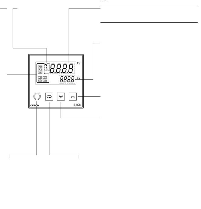
Operation Indicators
1.AL1 (alarm 1)
Lights when alarm 1 output is ON.
AL2 (alarm 2)
Lights when alarm 2 output is ON.
2.HB (heater burnout alarm display)
Lights when a heater burnout is detected.
The heater burnout alarm remains ON by setting the heater burnout latch. To reset, turn the power supply OFF and then ON or set the heater burnout alarm value to “0.0A.”
3.OT1, OT2 (control output 1, control output 2)
Lights when control output 1 and/or control output 2 (cool) are ON.
4.STP (stop)
Lights when control of the E5CN has been stopped. During control, this indicator lights when an event or the run/stop function has stopped, or this indicator is out.
5.CMW (communications writing control)
Lights when communications writing is enabled and is out when it is disabled.
Temperature Unit
The temperature unit is displayed when the display unit parameter is set to a temperature. Indication is determined by the currently selected “temperature unit” parameter set value. When this parameter is set to “°C,” “ ” is displayed, and when set to “°F,”
“ ” is displayed.
Level Key
Press this key to select the setup level. The setup level is selected in this order: “operation level” ←→ “adjustment level,” “initial setting level” ←→ “communications setting level.”
No. 1 Display
Displays the process value or parameter type.
No. 2 Display
Displays the set point, manipulated variable, or set value (setup) of the parameter.
Up Key
Each press of this key increases values displayed on the No.2 display. Holding down this key continuously increases values.
Down Key
Each press of this key decreases values displayed on the No.2 display. Holding down this key continuously decreases values.
Level + Mode Keys
This key combination sets the
E5CN to the “protect level.”
Mode Key
Press this key to select parameters within each level.
E5CN 


 E5CN
E5CN
Operation
INITIAL SETUP
On previous Controllers, sensor input type, alarm type and control period were set on DIP switches. These hardware settings are now set in parameters in setup menus. The  and
and  keys are used to switch between setup menus, and the amount of time that you hold the keys down determines which setup menu you move to. This section describes two typical examples.
Note: On the E5GN, the  Key is the
  Key.
Key.
1. ON/OFF Control
Typical Application Examples
Typical Example
|
Input type: |
0 K thermocouple -200 to 1300°C |
|
Control method: |
ON/OFF control |
|
Alarm type: |
2 upper limit |
|
Alarm value 1: |
20°C (For setting deviation) |
|
Set point: |
100°C |
Change only the alarm value 1 and set point. The rest must be left as default settings.
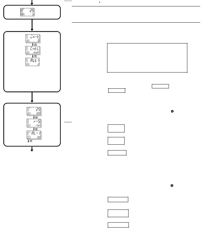
Setup procedure
Power ON
Set input specifications
Set control specifications
Set alarm type
Set the set point
Check operation state
Set alarm values
Power ON
Operation level
|
Process value/ |
|
|
set point |
|
|
Press |
key for at least |
|
three seconds. |
|
|
Control stops. |
|
|
Initial setting level |
|
|
Check input |
Input type |
|
type. |
|
|
Check that con- |
In ON/OFF |
|
trol is ON/OFF |
|
|
control. |
control |
|
Check alarm |
Alarm 1 |
|
|
type. |
||
|
type |
||
Press key for at least one second.
Operation level
Press 
 keys to set set point to “100 C.”
Make sure that control is running.
Press 
 keys to set alarm value to “20 C.”
Process value/ set point
During run
During stop
Alarm value 1
|
Start operation |
Start operation |
 Loading…