-
Contents
-
Table of Contents
-
Troubleshooting
-
Bookmarks
Quick Links
POWERWARE
9120
®
User’s Guide
6000VA
www.powerware.com
Related Manuals for Eaton POWERWARE 9120
Summary of Contents for Eaton POWERWARE 9120
-
Page 1
POWERWARE 9120 ® User’s Guide 6000VA www.powerware.com… -
Page 2: User Guide
POWERWARE 9120 6000VA User Guide Important Notice The UPS ground (earth) conductor carries leakage current from the loads in addition to any leakage current generated by the UPS. This UPS generates no more than 1 mA of current. To limit the total leakage current to 3.5 mA, the load leakage must be limited to 2.5 mA.
-
Page 3: If You Have A Question
Power Quality offices section). Eaton Power Quality’s service technicians have in- depth knowledge of the UPS and power problems. Eaton Power Quality may tell you the UPS must be returned. If this happens, we will give you a Return Authorisation (RA) number. When you return a Powerware 9120 to the factory for any reason, please use the original packing material in which your unit was shipped to you.
-
Page 4: Table Of Contents
Table of Contents Safety Instructions ……..2 UPS Features .
-
Page 5: Safety Instructions
For assistance, call Powerware Service or your local Powerware office. If the Powerware 9120 has been damaged during shipment, call your vendor immediately. If the Powerware 9120 is stored, the batteries should be recharged every 6 months. If stored above 25° Celsius, recharge the batteries more often.
-
Page 6: Ups Features
UPS Features The Powerware 9120 provides protection against power problems, including power outages, brownouts, and sudden increases in power. It also provides spike suppression and line noise fil- tering to protect your equipment. Front panel LEDs and an audible alarm keep you aware of the unit’s status.
-
Page 7: Installation
Installation Environment The UPS should be installed in a controlled environment. A controlled environment is one that is indoor, temperature controlled, free from conductive contaminants, dust, fumes and moisture. The UPS is intended for indoor use only. Provide adequate ventilation, 100 mm clearance at the rear of the UPS and 50 mm on the sides of the UPS.
-
Page 8: Rear Panel View
Rear Panel View Fig 2. Powerware 9120 6kVA Rear Panel…
-
Page 9: Connections To Mains And Load
Connections to Mains and Load The installation, wiring and connection must be carried out by qualified personnel only. The installation must comply with all current Wiring Rules and Regulations, Local, State and Federal statutes, Legislation and Regulations. CAUTION ! The UPS contains high voltage and current levels which could injure or kill personnel and damage equipment.
-
Page 10
Fig 4. AC Supply with Separate Bypass Supply Note: 1. Max Cable Size into Terminals is 10sq. mm. Stranded Cable 2. Currents quoted are for 240V AC units 3. For Wiring Diagram refer to Fig 6 Fig 6. AC Supply with Separate Bypass Supply Note: For Terminal Connection refer to Fig 4… -
Page 11
2.3.1 Installing the UPS (cont.) Isolate the Supply service and secure against reclosing. The Input and Output Circuit Breakers located at the rear of the UPS must be in the “OFF” position. Connect to the UPS in accordance with Fig 3 for a Single Supply Input or Fig 4 for a Dual Supply Input. -
Page 12: Quick Startup
3.0 Quick Startup Your Powerware 9120 6kVA UPS is designed for direct connection to a mains supply by a qualified electrican. When input power is connected and switched on the LCD backlight will illuminate and the fan will run, but no output power is available.
-
Page 13: Operation
4.0 Operation This section describes: • The UPS front panel • Standby mode • Turning the UPS on and off • Diagnostic tests • Starting the UPS on battery UPS Front Panel The UPS front panel indicates the UPS status and also identifies potential power problems. Figure 7 shows the UPS front panel indicators and controls.
-
Page 14: Turning The Ups On
Turning the UPS On After the UPS is connected to a power source, the fan turns on and the UPS enters Standby mode. To turn on the UPS, press and hold the button until you hear the UPS beep (approximately one second).
-
Page 15: Configuration
Configuration This section describes how to reconfigure options using the Configuration mode, including: input and output voltage and frequency, site wiring fault, and silencing the alarm. NOTE The UPS has been factory-configured with default settings appropriate for most installations. User configuration is not normally required. Configuration Mode ↵…
-
Page 16
Table 1. Configuration Mode Parameters Parameter LCD Message Description Default Settings Output Voltage Setting O/P V Setting To change the output voltage • Select 208, 220, 230, or 240V for 240V models. For 240V models: You are prompted to save this setting. O/P V= 240V Input Voltage Tolerance Bypass Volt Set… -
Page 17
Table 1. Configuration Mode Parameters (cont.) Parameter LCD Message Description Default Settings ↵ ↵ Manual Battery Test Manual BAT Test To initiate a manual battery test, press the button Battery Test twice when “Manual Battery Test” is displayed on the LCD. -
Page 18: Additional Ups Features
Optional Powerware communication cards Inverter Shutdown The Powerware 9120 includes a port that allows the UPS inverter to be switched off. This feature is designed to be used with Powerware External Maintenance Bypass Switches. Refer to the instructions provided with the switch for further information.
-
Page 19: Communication Slot
Refer to the power management software instructions for using the USB port. Communication Slot The Powerware 9120 UPS has a communication slot that allows quick installation of the optional SNMP/Web adapter or future communication interfaces. These interface adapters extend the capabilities of the Powerware 9120 system to provide compatibility with network and remote moni- toring/management systems.
-
Page 20: Relay Card
Relay Card (optional extra) This interface provides true relay contact output to peripheral devices. Outputs are user-selectable as normally open or normally closed. Table 3. Relay Card (AS/400) Pin Assignment Pin Number Signal Name Definition Direction Isolated common to pins 2 & 3 Line OK Relay contact;…
-
Page 21: Replacing The Batteries
8.0 Replacing the Batteries The Powerware 9120 batteries are user-replaceable and can be replaced while the Powerware 9120 has AC input applied and powers the loads. This means that, if necessary, you can replace the batteries while the UPS is running. Before you replace the batteries, make sure that you read the safety information below.
-
Page 22: How To Replace Internal Batteries
How to Replace Internal Batteries Use the following steps to replace the internal batteries: Remove screws where indicated (a). Using caution not to put stress on the LCD display cable, pull the top panel forward and place it on top of the UPS. Unscrew the bottom panel screws (b).
-
Page 23: Recyling The Used Battery
Pull the upper batteries out and place onto a flat, stable surface. Pull the lower batteries out and place onto a flat, stable surface. Remove the batteries from their cradles. See “Recyling the Used Battery” for proper dispos- Install the new batteries. Reinstall the trays and battery covers.
-
Page 24: Specifications
9.0 Specifications Powerware reserves the right to change specifications without prior notice. This section provides the following specifications for the Powerware 9120 6kVA model: • Electrical input and output • Environmental and safety • Weights and dimensions • Battery Table 4. Electrical Input…
-
Page 25
Table 6. Environmental and Safety 240V Models Operating Temperature 0°C to 40°C 0-1500 metres above sea level 0°C to 35°C 1500-3000 metres above sea level Optimal battery performance: 25°C Storage Temperature -15°C to 50°C Relative Humidity 0-95% noncondensing Operating Altitude Up to 3,000 metres above sea level Audible Noise Less than 55 dBA… -
Page 26: Troubleshooting
10.0 Troubleshooting If you have a question or problem, the troubleshooting table may help (See Table 8). If you need assis- tance, phone Powerware Service or your local Powerware office. Please have the model number and serial number (located on the rear of the unit) available. If the unit must be returned, Powerware will give you a Return Authorisation (RA) number.
-
Page 27
Table 8. Troubleshooting LCD Message or Possible Cause Action Condition UPS does not turn on. The UPS is not correctly Check connections to the power source. connected to the power source. The wall outlet is faulty. Have a qualified electrician test and repair the outlet. -
Page 28
Table 8. Troubleshooting (cont.) LCD Message or Possible Cause Action Condition Low Battery The battery is running low. 2 minutes or less of battery power remains 2 beeps every 5 seconds. (depending on load and battery charge). Prepare for a shutdown. Save your work and turn off your equipment. -
Page 29
Table 8. Troubleshooting (cont.) LCD Message or Possible Cause Action Condition Overcharge Batteries are over-charged. Save your work and turn off your equipment. Constant beep. Turn off the UPS. Contact your service representative. O/P Short Output short circuit. Save your work and turn off your equipment Constant beep. -
Page 30: Warranty
11.0 Warranty WARRANTY Information This Warranty is subject to Eaton Power Quality Pty Ltd (EPQ) standard Conditions of Sale which govern all sales of products by Eaton Power Quality Pty Ltd. EPQ products, in general, are warranted against failure due to faulty materials and/or work- manship for a period of two years from despatch date (ex EPQ store) as per invoice.
-
Page 31
Providing that the batteries are used within the limits as set out in the battery manufacturer’s warranty statement and are provided as an integral part of new equipment, they are guaran- teed for two years, from despatch date as per invoice. A copy of this warranty statement is available on request. -
Page 34: Powerware Australia/New Zealand Offices
Powerware Australia/New Zealand Offices Head Office — Sydney Eaton Power Quality Pty Ltd ABN 82 054 056 709 119-127 Wicks Road North Ryde NSW 2113 Phone: 61-2-9878 5000 Fax: 61-2-9887 2186 National Service and Repair Centre 1300 303 059 Web Site: www.powerware.com…
-
Page 35
You have purchased a UPS that will provide you with many years of service, protecting your equipment from surges, sags, and blackouts. This product incorporates the highest quality standards in engineering, manufacturing and testing, and carries a 2 year warranty against defects in material and workmanship. This product is backed by over 60 years of pride and integrity.
POWERWARE
9120
®
700, 1000, 1500, 2000 & 3000VA
User’s Guide
Important Notice
The UPS ground (earth) conductor carries leakage current from the loads in addition to
any leakage current generated by the UPS. This UPS generates no more than 1 mA of
current. To limit the total leakage current to 3.5 mA, the load leakage must be limited to
2.5 mA. The three-wire receptacle that you plug the UPS into must have a good (low-
impedance) ground (protective earth) connection to provide a safe path for leakage cur-
rent.
OMM91203kRev1.qxd
© Copyright 2007, Eaton Powerware. All rights reserved.
Скачать файл PDF «Powerware 9120 Инструкция по эксплуатации» (1009 Kb)
Популярность:
6706 просмотры
Подсчет страниц:
24 страницы
Тип файла:
Размер файла:
1009 Kb

Series 9 Power Protection
True Online Design
True online systems such as the
Powerware 9120 are the only type
of UPSs that completely isolate con-
nected equipment from all 9 of the
most common power problems:
Even when presented with the most
severe of these power problems, the
Powerware 9120 output remains
within a remarkable ±2% of nominal
voltage, meaning that your critical
system always receives clean power.
In addition, the Powerware 9120
transfers to battery with no break in
power, making it the perfect UPS for
equipment in environments plagued
by poor power.
Power Failures
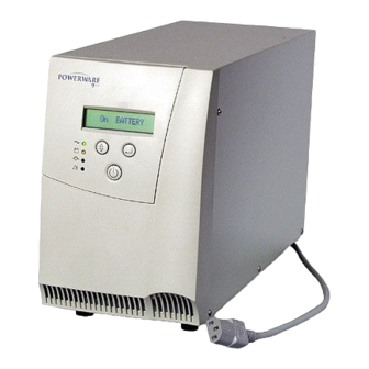
UPS On
On Battery
On Bypass
Alarm
Starts Up/Shuts down the UPS
Scroll meters/
Select UPS settings
Scroll UPS settings/
Select UPS setting parameter
LCD
Power Sags
Power Surges
Undervoltage
Electrical
Line Noise
Overvoltage
Frequency
Variation
Switching
Transient
Harmonic
Distortion
Powerware 9120 Features
Front Panel Display
Informative user interface with LCD, four LED and audible alarms.
Loads Segments, Network Transient Protector and Remote
Emergency Power Off (REPO) Port
Load Segments are groups of receptacles that
can be independently controlled and extend
battery backup times for critical equipment.
To preserve battery power for more critical
equipment connected to
Load Segment 1
, shut
down
Load Segment 2
supporting less critical
equipment.
Shut down and power up Load Segments in
user defined sequence.
The Network Transient Protector isolates your
modem, fax machine, and other electronic
equipment from “back door” power surges
The REPO port enables you to shut down the
UPS and connected equipment from a remote
location in an emergency.
1
2
3
4
1
2
3
4
Powerware 9120 1000 Shown
Hot-Swappable Batteries
You can hot-swap batteries without powering down the critical load. This makes it possible to extend
the life of your UPS without returning the unit for service.
Extended Battery Modules (EBMs)
Increasing battery backup time is as simple as plugging in an extended battery module. Hot-swap
capability on all Powerware 9120 models allow you to expand run time or replace battery modules
while keeping your critical load up and running.
The lead-acid batteries typically used in a UPS are considered viable as long as they
can maintain backup time of at least half that of new batteries. The illustration below
shows that batteries that are constantly trickle charged (as are virtually all other UPS
batteries on the market today) reach the end of their useful life in less than half the
time of batteries charged using ABM. ABM uses a three-stage charging technique that
not only doubles battery service life, but also optimizes battery recharge time and
provides advanced notification of the end of useful battery life.
Advanced Battery Management (ABM) Technology Doubles Battery Service Life
Data based upon tests performed by an independent battery manufacturer
Battery Features and Run times
VA
Standard Internal Battery
1 EBM
2 EBMs3 EBMs4 EBMs
5 EBMs
700
7/18
34/70
64/140
—
—
—
1000
7/18
36/80
66/155
—
—
—
1500
7/18
29/67
56/130
—
—
—
2000
12/34
49/107
93/195
140/310
192/403
240/504
3000
6/15
30/70
57/128
87/191
120/264
148/325
*Up to 2 EBMs can be connected to 700/1000/1500VA models and up to 5 EBMs can be connected to 2000/3000VA models. Run time chart provides typical information. Run times are approximate
and may vary with equipment, configuration, battery age, temperature, etc.
Battery Run Time Chart (in minutes full load/half load)*
Powerware 9120 — 1000VA shown with front cover
removed and battery shown sliding out.
Communications
Ī USB port (standard) allows UPS to communicate with Windows 98 and ME computers
Ī RS232 Port (standard) for interface with power management software
Ī SNMP/Web card (optional) adds direct control and monitoring capabilities in SNMP-based networks. Ability to
monitor UPS status and meters through web browser interface
Ī Relay card (optional) adds integration to industrial environment and building management systems, shutdown
for IBM AS/400.
S O F T W A R E S U I T E
LanSafe III &
CheckUPS
Network Shutdown
for UPSs
LanSafe III &
CheckUPS
Network Shutdown
for UPSs
OnliNet
SNMP-Based
Network Shutdown
& Monitoring
OnliNet
SNMP-Based
Network Shutdown
& Monitoring
Foreseer
Facility & Data
Center Management
Foreseer
Facility & Data
Center Management
Foreseer
Facility & Data
Center Management
LanSafe III &
CheckUPS
Network Shutdown
for UPSs
PowerVision
UPS Performance
Analysis &
Monitoring
PowerVision
UPS Performance
Analysis &
Monitoring
PowerVision
UPS Performance
Analysis &
Monitoring
OnliNet
SNMP-Based
Network Shutdown
& Monitoring
Powerware Software Suite
The industry’s most comprehensive software bundle, the Powerware Software Suite CD, is free and
included with every Powerware 9120 UPS.
Ī Software Wizard guides you through software selection and installation
Ī In addition to multimedia demonstrations, product data sheets, and video clips, the
Software Suite contains the following power management software:
– LanSafe III and CheckUPS Network shutdown for UPSs
– OnliNet (Lite / Vista / Centro): SNMP-based network shutdown and monitoring for UPSs
– PowerVision (30-day trial version): UPS performance analysis and monitoring
– Foreseer (demonstration): Facility and data center management
Powerware Software Suite
Software and Connectivity Options
Rear Panels: 120V, 208V and 230V Models
SNMP/Web Card shown
PW9120 700, 120V
PW9120 1000, 120V
PW9120 1500, 120V
PW9120 2000, 120V
PW9120 3000, 120V
PW9120 3000, 208V
PW9120 700i/1000i, 230V
PW9120 1500i, 230V
PW9120 2000i, 230V
PW9120 3000i, 230V
|
Detail Specifications: 609/609409-9120.pdf file (14 Feb 2023) |
Accompanying Data:
Powerware 9120 Power Supply, UPS PDF Operation & User’s Manual (Updated: Tuesday 14th of February 2023 01:45:02 PM)
Rating: 4.8 (rated by 68 users)
Compatible devices: 9390, 9125 Two-in-One UPS 5000, 5110, 9330, 9155, 9315, X-Slot USB Module, BPIV.
Recommended Documentation:
Text Version of Operation & User’s Manual
(Ocr-Read Summary of Contents, UPD: 14 February 2023)
-
10, Powerware 9120 7 3.0 Operation This section describes: • The UPS front panel • Standby mode • Turning the UPS on and off • Diagnostic tests • Starting the UPS on battery 3.1 UPS Front Panel The UPS front panel indicates the UPS status and also identifies potential power problems. Figure 6 shows the UPS front panel indicators and controls. Figure 6. UPS Front Panel NOTE If the alarm b…
-
22, Powerware 9120 19 Table 8. Battery Configuration 700 VA: (2) 12V, 9 Ah internal batteries; 24 Vdc 1000 VA: (3) 12V, 9 Ah internal batteries; 36 Vdc 1500 VA: (4) 12V, 9 Ah internal batteries; 48 Vdc 2000-3000 VA: (8) 12V, 9 Ah internal batteries; 96 Vdc Type Sealed, maintenance-free, valve-regulated, lead-acid Charging Approximately 4 hours to 90% usable capacity at nominal line voltage after full loa…
-
8, 5 Fig 4. 2000VA Rear Panel USB Port Communication Slot Communication Port Fan Inverter Shutdown Connector Input Connector IEC C14 10A Network Surge Suppression Battery Connector Load Segment 2 2 x Australian 10A Load Segment 1 3 x Australian 10A Fig 5. 3000VA Rear Panel USB Port Communication Slot Communication Port Fan Inverter Shutdown Connector Input Connecto…
-
2, POWERWARE ® 9120 700, 1000, 1500, 2000 & 3000VA User’s Guide Important Notice The UPS ground (earth) conductor carries leakage current from the loads in addition to any leakage current generated by the UPS. This UPS generates no more than 1 mA of current. To limit the total leakage current to 3.5 mA, the load leakage must be limited to 2.5 mA. The three-wire r…
-
27, Powerware 9120 24 10. Warranty WARRANTY Information This Warranty is subject to Eaton Power Quality Pty Ltd (EPQ) standard Conditions of Sale, which govern all sales of products by Eaton Power Quality Pty Ltd. 1. EPQ products, in general, are warranted against failure due to faulty materials and/or workmanship for a period of two years from despatch date (ex EPQ store) as per invoice. The Ferroresonant and 95…
-
18, Powerware 9120 15 7.0 Replacing the Batteries The Powerware 9120 batteries are user-replaceable and can be replaced while the Powerware 9120 has AC input applied and powers the loads. This means that, if necessary, you can replace the batteries while the UPS is running. Before you replace the batteries, make sure that you read the safety information below. Note: If you have a power o…
-
17, 14 5.7 Relay Card This interface provides true relay contact output to peripheral devices. Outputs are user-selectable as normally open or normally closed. Table 2. Relay Card (AS/400) Pin Assignment Pin Number Signal Name Definition Direction 1 — Isolated common to pins 2 & 3 — 2 Line OK Relay contact; closed to pin 1 — 3 Line Failure Relay contact; closed to pin 1 — 4 — Isolated common to …
-
30, 6.Please specify the equipment being protected by your Powerware UPS? Brand………………………………….Model ……………………………. Operating System ……………………. 7.How would you classify your type of business? Retail Wholesale/Distribution Manufacturing Telecommunications Government/Eduction Banking/Finance Rest…
-
9, 6 2.0 Quick Startup 1 Your Powerware 9120 UPS has a removable power cord. Connect the power cord to the back of the unit and plug the UPS into a wall outlet. The LCD backlight will illuminate and the fan will run, but no output power is available. 2 Let the unit charge the battery for at least 3 hours. You may use the unit while the battery charges, but the battery backup runtime will be reduced…
-
6, 3 Fig 1. Powerware 9120 Controls and Indicators 1.0 UPS Features The Powerware 9120 provides protection against power problems, including power outages, brownouts, and sudden increases in power. It also provides spike suppression and line noise fil- tering to protect your equipment. Front panel LEDs and an audible alarm keep you aware of the unit’s status. Use the drawings on this and th…
Recommended Instructions:
AH-C751, Designjet Z6100 series, XGPS170, EL52-2


-
HI/58-101/15Ejemplo de distribución de alimentadores con teléfonos digitales.autapower supplies distribution-Distribución de alimentadoresA L I M E N T A D O R — P O W E R S U P P L YA T F — 9 8RC+-RC( )+-++—++—Power supplies distributor example with digital phonesATF-98ATENCIÓNNO conectar los alimentadores en paraleloWARNINGDO NOT connect to the power supply in paralelREF:7 …
ATF-98 2
-
IPS12060SAlimentatore/Caricabatteria switchingda 13,8V 3AIl modulo alimentatore caricabatteria IPS12060S è stato sviluppato secondo i criteri di qualità, affidabilitàe prestazioni adottati dalla INIM Electronics. I componenti utilizzati garantiscono idonei requisiti difunzionamento quando le condizioni ambientali esterne al contenitore della centrale o della st …
IPS12060S 8
-
Robert Bosch Power Tools GmbH 70538 StuttgartGERMANYwww.bosch-pt.com1 609 92A 5YS (2020.10) O / 92de Originalbetriebsanleitungen Original instructionsfr Notice originalees Manual originalpt Manual originalit Istruzioni originalinl Oorspronkelijke gebruiksaanwijzingda Original brugsanvisningsv Bruksanvisning i originalno Original driftsinstruksfi Alkuperäiset ohjeetel Πρωτότυπο οδηγ …
AL 1810 CV 91
-
I. Model Numbers8Ah Max28.2VAC2.50A36Ah4.0A24VDCPS5-24040-B03-UL/CSA/ULC 013XX20Ah Max17.5VAC1.25A36Ah4.0A12VDCPS5-12040-B03-UL/CSA/ULC 013XX8Ah Max28.2VAC2.50A38Ah4.0A24VDCPS5-BFS-24-UL/CSA/ULC 0131020Ah Max17.5VAC1.25A38Ah4.0A12VDCPS5-BFS-12-UL/CSA/ULC 01309BatteryStorage inCabinetXFMRVoltageMax. ACInputCurrentMax.BatteryCapacitySystemCurrentSystemVoltageM …
PS5-BFS-12-UL 2