Материал из BikesWiki — энциклопедия японских мотоциклов
Перейти к: навигация, поиск

Yamaha XJ6 Diversion
Ниже представлены прямые ссылки на скачку сервисной документации.
Для Yamaha XJ6 Diversion
- Руководство пользователя (Owners Manual) для Yamaha XJ6 Diversion (на русском)
- Сервисный мануал (Service Manual) для Yamaha XJ6S(A) (Европа, 2009)
- Сервисный мануал (Service Manual) для Yamaha FZ6R (США, 2009)
- Каталог запчастей (микрофиши) для Yamaha XJ6N (A) (2010)
- Каталог запчастей (микрофиши) для Yamaha XJ6S (2010)
- Каталог запчастей (микрофиши) для Yamaha XJ6SA (2010)
Обзор модели
- Yamaha XJ6 Diversion
Источник — «https://bikeswiki.ru/index.php?title=Yamaha_XJ6_Diversion:_мануалы&oldid=10057»
Категория:
- Сервисная документация
- Manuals
- Brands
- Yamaha Manuals
- Motorcycle
- XJ6
- Owner’s manual
-
Contents
-
Table of Contents
-
Troubleshooting
-
Bookmarks
Quick Links
OWNER’S MANUAL
XJ6
XJ6 ABS
MOTORCYCLE
Read this manual carefully before oper-
ating this vehicle.
XJ6N
XJ6NA
B61-28199-E1
Related Manuals for Yamaha XJ6
Summary of Contents for Yamaha XJ6
-
Page 1
OWNER’S MANUAL XJ6 ABS MOTORCYCLE Read this manual carefully before oper- ating this vehicle. XJ6N XJ6NA B61-28199-E1… -
Page 2
EAU69471 Read this manual carefully before operating this vehicle. This manual should stay with this vehicle if it is sold. YAMAHA MOTOR ELECTRONICS CO., LTD. 1450-6, Mori, Mori-machi, Shuchi-gun, Shizuoka-ken, 437-0292 Japan DECLARATION of CONFORMITY Product: IMMOBILIZER Model: 5VS-00 Supplied by… -
Page 3
EAU10103 Welcome to the Yamaha world of motorcycling! As the owner of the XJ6N / XJ6NA, you are benefiting from Yamaha’s vast expe- rience and newest technology regarding the design and manufacture of high- quality products, which have earned Yamaha a reputation for dependability. -
Page 4: Important Manual Information
*Product and specifications are subject to change without notice. EAU10201 XJ6N / XJ6NA OWNER’S MANUAL ©2015 by Yamaha Motor Co., Ltd. 1st edition, August 2015 All rights reserved. Any reprinting or unauthorized use without the written permission of Yamaha Motor Co., Ltd.
-
Page 5: Table Of Contents
Table of contents Safety information ……1-1 Periodic maintenance and adjustment ……..6-1 Description ……..2-1 Owner’s tool kit……. 6-2 Left view ……….2-1 Periodic maintenance chart for the Right view……..2-2 emission control system….6-3 Controls and instruments….2-3 General maintenance and lubrication chart……6-4 Instrument and control functions..3-1 Removing and installing the Immobilizer system ……3-1…
-
Page 6
Table of contents Battery ………. 6-33 Replacing the fuses…… 6-34 Replacing the headlight bulb..6-36 Replacing the auxiliary light bulb ……….. 6-38 Replacing the brake/tail light bulb ……….. 6-39 Replacing a turn signal light bulb ……….. 6-39 Replacing the license plate light bulb ……….. -
Page 7: Safety Information
Safety information EAU1028B an accident or equipment damage. See page 4-1 for a list of pre-operation checks. Be a Responsible Owner This motorcycle is designed to As the vehicle’s owner, you are re- carry the operator and a passen- sponsible for the safe and proper oper- ger.
-
Page 8
Safety information Many accidents involve inexperi- • The passenger should always enced operators. In fact, many op- hold onto the operator, the seat erators who have been involved in strap or grab bar, if equipped, accidents do not even have a cur- with both hands and keep both rent motorcycle license. -
Page 9
Safety information Avoid Carbon Monoxide Poisoning extra care when riding a motorcycle All engine exhaust contains carbon that has added cargo or accessories. monoxide, a deadly gas. Breathing Here, along with the information about carbon monoxide can cause head- accessories below, are some general aches, dizziness, drowsiness, nausea, guidelines to follow if loading cargo to confusion, and eventually death. -
Page 10
Genuine does not in any way reduce Yamaha accessories, which are avail- ground clearance or cornering able only from a Yamaha dealer, have clearance, limit suspension travel, been designed, tested, and approved steering travel or control opera- by Yamaha for use on your vehicle. -
Page 11: Specifications
Safety information operator and may limit control torcycle, such as the frame or up- ability, therefore, such accesso- per front fork triple clamp (and not, ries are not recommended. for example, to rubber-mounted Use caution when adding electri- handlebars or turn signals, or cal accessories.
-
Page 12: Description
Description EAU63371 Left view 1. Air filter element (page 6-16) 2. Idle adjusting screw (page 6-17) 3. Seat lock (page 3-18) 4. Fuses (page 6-34) 5. Owner’s tool kit (page 6-2) 6. Storage compartment (page 3-20) 7. Shift pedal (page 3-12) 8.
-
Page 13: Right View
Description EAU63391 Right view 1. Helmet holder (page 3-19) 2. Battery (page 6-33) 3. Rear brake fluid reservoir (page 6-25) 4. Engine oil filler cap (page 6-9) 5. Fuel tank cap (page 3-15) 6. Radiator cap (page 6-12) 7. Coolant reservoir (page 6-12) 8.
-
Page 14: Controls And Instruments
Description EAU63401 Controls and instruments 1. Clutch lever (page 3-12) 2. Left handlebar switches (page 3-10) 3. Main switch/steering lock (page 3-2) 4. Multi-function meter unit (page 3-6) 5. Front brake fluid reservoir (page 6-25) 6. Right handlebar switches (page 3-10) 7.
-
Page 15: Instrument And Control Functions
Do not grind any key or alter its cess, take the vehicle along with all shape. three keys to a Yamaha dealer to have Do not disassemble the plastic them re-registered. Do not use the key part of any key.
-
Page 16: Main Switch/Steering Lock
Instrument and control functions Keep the standard keys as well EAU10474 Main switch/steering lock as keys of other immobilizer systems away from this vehi- cle’s code re-registering key. Keep other immobilizer system keys away from the main switch as they may cause signal inter- ference.
-
Page 17
Instrument and control functions To unlock the steering EWA10062 WARNING Never turn the key to “OFF” or “LOCK” while the vehicle is moving. Otherwise the electrical systems will be switched off, which may result in loss of control or an accident. EAU10687 LOCK The steering is locked and all electrical… -
Page 18: Indicator Lights And Warning Lights
“ON”, or if the warning light remains on after confirming that the oil level is correct (see page 6-9), have a Yamaha dealer check the vehicle. 1. Turn signal indicator light “ ”…
-
Page 19
” The ABS may not work correctly. If any This warning light comes on or flashes of the above occurs, have a Yamaha if a problem is detected in the electrical dealer check the system as soon as circuit monitoring the engine. If this oc- possible. -
Page 20: Multi-Function Meter Unit
“ON”, making any setting changes to the or if the indicator light remains on, have multi-function meter unit. Changing a Yamaha dealer check the electrical settings while riding can distract the circuit. operator and increase the risk of an The self-diagnosis device also detects accident.
-
Page 21
Instrument and control functions Clock The key must be turned to “ON” before you can use the “SELECT” and “RESET” buttons. For the UK: To switch the speed- ometer and odometer/tripmeter displays between kilometers and miles, press the “SELECT” button for one second. -
Page 22
“ ” 0.70 Imp.gal), the left segment of the will flash repeatedly. If this occurs, fuel meter will start flashing, and the have a Yamaha dealer check the elec- odometer display will automatically trical circuit. change to the fuel reserve tripmeter mode “F-TRIP”… -
Page 23
Yamaha dealer check the vehicle. goes down. If the temperature does The self-diagnosis device also detects not go down, stop the engine. (See problems in the immobilizer system page 6-46.) -
Page 24: Handlebar Switches
” key and both standard keys to a 4. Horn switch “ ” 5. Hazard switch “ ” Yamaha dealer and have the stan- dard keys re-registered. Right ECA11591 NOTICE If the display indicates an error co- de, the vehicle should be checked as soon as possible in order to avoid engine damage.
-
Page 25
Instrument and control functions The hazard lights are used in case of an EAU12461 Turn signal switch “ ” emergency or to warn other drivers To signal a right-hand turn, push this when your vehicle is stopped where it switch to “ ”. -
Page 26: Clutch Lever
Instrument and control functions EAU12822 EAU12872 Clutch lever Shift pedal 1. Clutch lever 1. Shift pedal The clutch lever is located on the left The shift pedal is located on the left side of the handlebar. To disengage side of the motorcycle and is used in the clutch, pull the lever toward the combination with the clutch lever when handlebar grip.
-
Page 27: Brake Lever
Instrument and control functions EAU26825 EAU12944 Brake lever Brake pedal The brake lever is located on the right side of the handlebar. To apply the front brake, pull the lever toward the throttle grip. 1. Brake pedal The brake pedal is located on the right side of the motorcycle.
-
Page 28: Abs (For Abs Models)
This ABS has a test mode which EAU51802 ABS (for ABS models) allows the owner to experience The Yamaha ABS (Anti-lock Brake the pulsation at the brake lever or System) features a dual electronic con- brake pedal when the ABS is op- trol system, which acts on the front and erating.
-
Page 29: Fuel Tank Cap
Instrument and control functions EAU13075 EAU13222 Fuel tank cap Fuel Make sure there is sufficient gasoline in the tank. EWA10882 WARNING Gasoline and gasoline vapors are extremely flammable. To avoid fires and explosions and to reduce the risk of injury when refueling, follow these instructions.
-
Page 30
Your Yamaha engine has been de- signed to use regular unleaded gaso- line with a research octane number of 3-16… -
Page 31: Fuel Tank Breather Hose And Overflow Hose
Instrument and control functions EAU55512 EAU13434 Fuel tank breather hose and Catalytic converter overflow hose This model is equipped with a catalytic converter in the exhaust system. EWA10863 WARNING The exhaust system is hot after op- eration. To prevent a fire hazard or burns: …
-
Page 32: Seat
Instrument and control functions EAU32981 Seat Make sure that the seat is properly se- cured before riding. To remove the seat 1. Insert the key into the seat lock, and then turn it counterclockwise. 1. Seat lock 2. Unlock. 2. While holding the key in that posi- tion, lift the rear of the seat up, and then pull the seat off.
-
Page 33: Helmet Holder
Instrument and control functions 3. Place the helmet on the right side EAU46752 Helmet holder of the vehicle, and then install the seat. WARNING! Never ride with a helmet attached to the helmet holder, since the helmet may hit objects, causing loss of control and possibly an accident.
-
Page 34: Storage Compartment
Storage compartment Handlebar position The handlebar can be adjusted to one of two positions to suit the rider’s pref- erence. Have a Yamaha dealer adjust the position of the handlebar. 1. Storage compartment The storage compartment is located under the seat. (See page 3-18.) When storing the Owner’s Manual or…
-
Page 35: Adjusting The Shock Absorber Assembly
Do not dispose of a damaged or worn-out shock absorber as- sembly yourself. Take the shock absorber assembly to a Yamaha dealer for any service. 1. Extension bar 2. Special wrench 3. Spring preload adjusting ring 4.
-
Page 36: Sidestand
Therefore, check this system regularly and have a Yamaha dealer repair it if it does not function properly. 3-22…
-
Page 37
Does the engine start? The neutral switch may not be working correctly. The motorcycle should not be ridden until checked by a Yamaha dealer. With the engine still running: 6. Move the sidestand up. 7. Keep the clutch lever pulled. -
Page 38: For Your Safety — Pre-Operation Checks
Do not operate the vehicle if you find any problem. If a problem cannot be corrected by the procedures provided in this manual, have the vehicle inspected by a Yamaha dealer. Before using this vehicle, check the following points:…
-
Page 39
• Tighten if necessary. Instruments, lights, • Check operation. — signals and switches • Correct if necessary. • Check operation of ignition circuit cut-off system. Sidestand switch • If system is not working correctly, have Yamaha dealer 3-22 check vehicle. -
Page 40: Operation And Important Riding Points
This model is equipped with: there is a control or function you do not a lean angle sensor to stop the en- understand, ask your Yamaha dealer. gine in case of a turnover. In this EWA10272 case, the display will indicate error…
-
Page 41: Starting The Engine
The neutral indi- the clutch lever pulled and the cator light should come on. If not, sidestand up. ask a Yamaha dealer to check the See page 3-22 for more informa- electrical circuit. tion. 3. Start the engine by pushing the 1.
-
Page 42: Shifting
Operation and important riding points EAU16673 and drive train, which are not Shifting designed withstand shock of forced shifting. 1. Shift pedal 2. Neutral position Shifting gears lets you control the amount of engine power available for starting off, accelerating, climbing hills, etc.
-
Page 43: Tips For Reducing Fuel Consumption
The vehicle can now be operated nor- mally. ECA10311 NOTICE Keep the engine speed out of the tachometer red zone. If any engine trouble should oc- cur during the engine break-in period, immediately have a Yamaha dealer check the vehi- cle.
-
Page 44: Parking
Operation and important riding points EAU17214 Parking When parking, stop the engine, and then remove the key from the main switch. EWA10312 WARNING Since the engine and exhaust system can become very hot, park in a place where pedestri- ans or children are not likely to touch them and be burned.
-
Page 45: Periodic Maintenance And Adjustment
If you are not familiar with vehicle ser- vice, have a Yamaha dealer perform service. EWA15123 WARNING Turn off the engine when performing…
-
Page 46: Owner’s Tool Kit
If you do not have the tools or experi- ence required for a particular job, have a Yamaha dealer perform it for you.
-
Page 47: Periodic Maintenance Chart For The Emission Control System
From 50000 km (30000 mi), repeat the maintenance intervals starting from 10000 km (6000 mi). Items marked with an asterisk should be performed by a Yamaha dealer as they require special tools, data and technical skills. EAU63321…
-
Page 48: General Maintenance And Lubrication Chart
Periodic maintenance and adjustment EAU64031 General maintenance and lubrication chart ODOMETER CHECK OR READINGS MAINTENANCE JOB ITEM X 1000 km X 1000 mi √ Air filter element • Replace. • Check operation. √ √ √ √ √ Clutch • Adjust. •…
-
Page 49
Periodic maintenance and adjustment ODOMETER CHECK OR READINGS MAINTENANCE JOB ITEM X 1000 km X 1000 mi • Make sure that all nuts, bolts √ √ √ √ √ 13 * Chassis fasteners and screws are properly tight- ened. Brake lever pivot √… -
Page 50
Periodic maintenance and adjustment ODOMETER CHECK OR READINGS MAINTENANCE JOB ITEM X 1000 km X 1000 mi Lights, signals and • Check operation. √ √ √ √ √ √ 28 * • Adjust headlight beam. switches EAU18681 Air filter •… -
Page 51: Removing And Installing The Cowling And Panels
Periodic maintenance and adjustment To install the cowling EAU18724 Removing and installing the Place the cowling in the original posi- cowling and panels tion, and then install the bolts. The cowling and panels shown need to be removed to perform some of the EAU56070 maintenance jobs described in this chapter.
-
Page 52: Checking The Spark Plugs
The spark plugs are important engine components, which should checked periodically, preferably by a Yamaha dealer. Since heat and depos- its will cause any spark plug to slowly erode, they should be removed and checked in accordance with the peri- odic maintenance and lubrication 1.
-
Page 53: Engine Oil And Oil Filter Cartridge
Periodic maintenance and adjustment EAU46723 Engine oil and oil filter car- tridge The engine oil level should be checked before each ride. In addition, the oil must be changed and the oil filter car- tridge replaced at the intervals speci- fied in the periodic maintenance and lubrication chart.
-
Page 54
An oil filter wrench is available at a gasket to drain the oil from the Yamaha dealer. crankcase. 6. Apply a thin coat of clean engine oil to the O-ring of the new oil filter cartridge. -
Page 55
Periodic maintenance and adjustment 9. Refill with the specified amount of the recommended engine oil, and then install and tighten the oil filler cap. Recommended engine oil: See page 8-1. Oil quantity: Oil change: 2.50 L (2.64 US qt, 2.20 Imp.qt) With oil filter removal: 1. -
Page 56: Coolant
Yamaha dealer check and lubrication chart. the vehicle. 11. Turn the engine off, wait a few mi-…
-
Page 57
[EWA10382] be protected against frost and corrosion. If water has been added to the coolant, have a Yamaha dealer check the anti- freeze content of the coolant as soon as possible, otherwise the effectiveness of the coolant will be reduced. -
Page 58
Periodic maintenance and adjustment 1. Radiator cap 1. Bolt 2. Radiator cap retaining bolt 2. Coolant reservoir cover 3. Radiator cap retainer 3. Coolant reservoir 5. Remove the coolant reservoir 7. Drain the coolant from the coolant breather hose from the guide, and reservoir by turning it upside then remove the coolant reservoir down. -
Page 59
14. Install the coolant reservoir cap. the vehicle for coolant leakage. If 15. Start the engine, let it idle for sev- coolant is leaking, have a Yamaha eral minutes, and then turn it off. dealer check the cooling system. 16. Remove the radiator cap to check 20. -
Page 60: Replacing The Air Filter Element
If any hose is damaged, have a Yamaha dealer replace the hose before 1. Air filter case cover 2. Screw 4. Pull the air filter element out.
-
Page 61: Adjusting The Engine Idling Speed
1. Original position (paint mark) 8. Install the fuel tank bolts. 9. Install the seat. 1. Idle adjusting screw Engine idling speed: 1250–1350 r/min If the specified idling speed cannot be obtained as described above, have a Yamaha dealer make the adjustment. 6-17…
-
Page 62: Checking The Throttle Grip Free Play
Measure the throttle grip free play as and/or engine noise. To prevent this shown. from occurring, the valve clearance must be adjusted by a Yamaha dealer at the intervals specified in the periodic maintenance and lubrication chart. 1. Throttle grip free play Throttle grip free play: 3.0–5.0 mm (0.12–0.20 in)
-
Page 63: Tires
The tires must be checked before each ride. If the center tread depth reaches the specified limit, if the tire has a nail or glass fragments in it, or if the side- wall is cracked, have a Yamaha dealer replace the tire immediately. 6-19…
-
Page 64
EWA10472 their suitability for further use. WARNING EWA10902 Have a Yamaha dealer replace WARNING excessively worn tires. Besides The front and rear tires should being illegal, operating the vehi- be of the same make and de-… -
Page 65: Cast Wheels
160/60 ZR17M/C (69W) ride. If any damage is found, have Manufacturer/model: BRIDGESTONE/BT021R a Yamaha dealer replace the DUNLOP/SPORTMAX- wheel. Do not attempt even the ROADSMART smallest repair to the wheel. A de- FRONT and REAR:…
-
Page 66: Adjusting The Clutch Lever Free Play
Periodic maintenance and adjustment EAU46731 Adjusting the clutch lever free play 1. Locknut 2. Clutch lever free play adjusting nut 4. Tighten the locknut. 1. Clutch lever free play adjusting bolt 2. Clutch lever free play The clutch lever free play should mea- sure 10.0–15.0 mm (0.39–0.59 in) as shown.
-
Page 67: Checking The Brake Lever Free Play
2. Rear brake light switch adjusting nut brake lever end. If there is free play, The brake light, which is activated by have a Yamaha dealer inspect the the brake pedal and brake lever, brake system. should come on just before braking…
-
Page 68: Checking The Front And Rear Brake Pads
1. Brake pad wear indicator groove indicator groove almost appears, have Each front brake pad is provided with a a Yamaha dealer replace the brake wear indicator groove, which allows pads as a set. you to check the brake pad wear with- out having to disassemble the brake.
-
Page 69: Checking The Brake Fluid Level
Specified brake fluid: brake system for leakage. If the brake DOT 4 fluid level goes down suddenly, have a Yamaha dealer check the cause before EWA16011 further riding. WARNING Improper maintenance can result in loss of braking ability.
-
Page 70: Changing The Brake Fluid
Periodic maintenance and adjustment EAU22733 EAU22762 Changing the brake fluid Drive chain slack Have a Yamaha dealer change the The drive chain slack should be brake fluid at the intervals specified in checked before each ride and adjusted the periodic maintenance and lubrica- if necessary.
-
Page 71
Periodic maintenance and adjustment 2. To tighten the drive chain, turn the drive chain slack adjusting nut at each end of the swingarm in direc- tion (a). To loosen the drive chain, turn the adjusting nut at each end of the swingarm in direction (b), and then push the rear wheel for- ward. -
Page 72: Cleaning And Lubricating The Drive Chain
If a cable is wet areas. Service the drive chain as damaged or does not move smoothly, follows. have a Yamaha dealer check or re- place it. WARNING! Damage to the ECA10584 NOTICE outer housing of cables may result…
-
Page 73: Checking And Lubricating The Throttle Grip And Cable
In pedals should be checked before each addition, the cable should be lubricat- ride, and the pedal pivots should be lu- ed by a Yamaha dealer at the intervals bricated if necessary. specified in the periodic maintenance Brake pedal chart.
-
Page 74: Checking And Lubricating The Brake And Clutch Levers
EWA10732 Clutch lever WARNING If the sidestand does not move up and down smoothly, have a Yamaha dealer check or repair it. Otherwise, the sidestand could contact the ground and distract the operator, re- sulting in a possible loss of control.
-
Page 75: Lubricating The Swingarm Pivots
1. Place the vehicle on a level surfa- The swingarm pivots must be lubricat- ce and hold it in an upright posi- ed by a Yamaha dealer at the intervals tion. WARNING! To avoid injury, specified in the periodic maintenance securely support the vehicle so and lubrication chart.
-
Page 76: Checking The Steering
If any free smoothly, have a Yamaha dealer play can be felt, have a Yamaha check the wheel bearings. dealer check or repair the steer- ing.
-
Page 77: Battery
CHILDREN. 1. Battery To charge the battery 2. Negative battery lead (black) Have a Yamaha dealer charge the bat- 3. Positive battery lead (red) tery as soon as possible if it seems to have discharged. Keep in mind that the The battery is located under the seat.
-
Page 78: Replacing The Fuses
Periodic maintenance and adjustment 3. Fully charge the battery before EAU47174 Replacing the fuses installation. NOTICE: When in- The main fuse and the fuse boxes, stalling the battery, be sure the which contain the fuses for the individ- key is turned to “OFF”, then ual circuits, are located under the seat.
-
Page 79
4. ABS motor fuse 4. If the fuse immediately blows 5. Spare fuse 6. Headlight fuse again, have a Yamaha dealer 7. Ignition fuse check the electrical system. 8. Signaling system fuse 9. Backup fuse (for clock and immobilizer sys- tem) 10.Fuel injection system fuse… -
Page 80: Replacing The Headlight Bulb
Periodic maintenance and adjustment EAU46813 Replacing the headlight bulb This model is equipped with a halogen bulb headlight. If the headlight bulb burns out, replace it as follows. ECA10651 NOTICE Take care not to damage the follow- ing parts: Headlight bulb 1.
-
Page 81
Periodic maintenance and adjustment 6. Place a new headlight bulb into position, and then secure it with the bulb holder. 7. Install the headlight bulb cover, and then connect the coupler. 8. Fit the projection on the headlight unit into the grommet in the head- light stay, and then install the headlight unit by installing the bolts. -
Page 82: Replacing The Auxiliary Light Bulb
6-36.) 2. Remove the auxiliary light coupler (together with the socket and bulb) by turning the coupler coun- 11. Have a Yamaha dealer adjust the terclockwise. headlight beam if necessary. 1. Auxiliary light coupler 3. Remove the burnt-out bulb by pulling it out.
-
Page 83: Replacing The Brake/Tail Light Bulb
Periodic maintenance and adjustment EAU70880 EAU24205 Replacing the brake/tail light Replacing a turn signal light bulb bulb 1. Remove the seat. (See page 3-18.) 1. Remove the turn signal light lens 2. Remove the brake/tail light bulb by removing the screw. socket (together with the bulb) by turning it counterclockwise.
-
Page 84: Replacing The License Plate Light Bulb
Periodic maintenance and adjustment EAU24314 EAU24351 Replacing the license plate Supporting the motorcycle light bulb Since this model is not equipped with a centerstand, follow these precautions 1. Remove the license plate light unit when removing the front and rear by removing the screws.
-
Page 85: Front Wheel (For Non-Abs Models)
Front wheel (for non-ABS brake pads will be forced shut. models) [ECA11052] EWA14841 WARNING For the ABS model, have a Yamaha dealer remove and install the wheel. EAU56270 To remove the front wheel EWA10822 WARNING 1. Brake caliper 2.
-
Page 86: Rear Wheel (For Non-Abs Models)
Front wheel axle pinch bolt: WARNING 19 Nm (1.9 m·kgf, 14 ft·lbf) Brake caliper bolt: For the ABS model, have a Yamaha 40 Nm (4.0 m·kgf, 29 ft·lbf) dealer remove and install the wheel. 6. Push down hard on the handlebar…
-
Page 87
Periodic maintenance and adjustment 7. Remove the wheel. NOTICE: Do not apply the brake after the wheel and brake disc have been removed, otherwise the brake pads will be forced shut. [ECA11073] To install the rear wheel 1. Install the wheel and the brake cal- iper bracket by inserting the wheel axle from the right side. -
Page 88: Troubleshooting
The following troubleshooting charts represent quick and easy procedures for checking these vital systems your- self. However, should your motorcycle require any repair, take it to a Yamaha dealer, whose skilled technicians have the necessary tools, experience, and know-how to service the motorcycle properly.
-
Page 89: Troubleshooting Charts
Check the vehicle. compression. 4. Compression The engine does not start. There is compression. Have a Yamaha dealer check the vehicle. Operate the electric starter. There is no Have a Yamaha dealer check the vehicle. compression. 6-45…
-
Page 90
Start the engine. If the engine overheats again, The coolant level is have a Yamaha dealer check and repair the cooling system. If coolant is not available, tap water can be temporarily used instead, provided that it is changed to the recommended coolant as soon as possible. -
Page 91: Motorcycle Care And Storage
Rust and corrosion can develop matte colored finished parts. Be even if high-quality components are sure to consult a Yamaha dealer for used. A rusty exhaust pipe may go un- advice on what products to use be- noticed on a car, however, it detracts fore cleaning the vehicle.
-
Page 92
Motorcycle care and storage fected area any longer than in- scratching. Some cleaning structed. Also, thoroughly rinse compounds for plastic may the area off with water, immedi- leave scratches on the wind- ately dry it, and then apply a cor- shield. -
Page 93
Consult a Yamaha dealer for ad- 4. To prevent corrosion, it is recom- vice on what products to use. mended to apply a corrosion pro- … -
Page 94: Storage
Motorcycle care and storage der head so that the electrodes EAU26183 Storage are grounded. (This will limit sparking during the next step.) Short-term d. Turn the engine over several Always store your motorcycle in a cool, times with the starter. (This will dry place and, if necessary, protect it coat the cylinder walls with oil.) against dust with a porous cover.
-
Page 95
Motorcycle care and storage Make any necessary repairs before storing the motorcycle. -
Page 96: Specifications
Specifications Dimensions: Engine oil quantity: Oil change: Overall length: 2.50 L (2.64 US qt, 2.20 Imp.qt) 2120 mm (83.5 in) With oil filter removal: Overall width: 2.80 L (2.96 US qt, 2.46 Imp.qt) 770 mm (30.3 in) Coolant quantity: Overall height: 1085 mm (42.7 in) Coolant reservoir (up to the maximum level Seat height:…
-
Page 97
Specifications 2nd: 90 kg (198 lb) load — maximum load: 1.947 (37/19) Front: 3rd: 250 kPa (2.50 kgf/cm², 36 psi) 1.556 (28/18) Rear: 4th: 290 kPa (2.90 kgf/cm², 42 psi) 1.333 (32/24) Front wheel: 5th: Wheel type: 1.190 (25/21) Cast wheel 6th: Rim size: 1.083 (26/24) -
Page 98
Specifications Battery: Radiator fan motor fuse: 20.0 A Model: Fuel injection system fuse: GT12B-4 10.0 A Voltage, capacity: ABS control unit fuse: 12 V, 10.0 Ah (10 HR) 7.5 A (XJ6NA) Headlight: ABS motor fuse: Bulb type: 30.0 A (XJ6NA) Halogen bulb Bulb wattage ×… -
Page 99: Consumer Information
Yamaha dealer. area. VEHICLE IDENTIFICATION NUMBER: EAU26442 Engine serial number…
-
Page 100
Consumer information space provided. This information will be needed when ordering spare parts from a Yamaha dealer. -
Page 101: Index
Index Handlebar switches ……3-10 Hazard switch ……..3-11 ABS (for ABS models) ……3-14 Headlight bulb, replacing…… 6-36 ABS warning light (for ABS models)..3-5 Helmet holder ……..3-19 Air filter element, replacing….6-16 High beam indicator light……3-4 Auxiliary light bulb, replacing ….
-
Page 102
Index Throttle grip free play, checking …6-18 Tires …………6-19 Tool kit …………6-2 Troubleshooting……..6-44 Troubleshooting charts……6-45 Turn signal indicator light …….3-4 Turn signal light bulb, replacing….6-39 Turn signal switch ………3-11 Valve clearance……..6-18 Vehicle identification number ….9-1 Wheel bearings, checking…..6-32 Wheel, front (for non-ABS models) ..6-41 Wheel, rear (for non-ABS models) ..6-42 Wheels ……….6-21 10-2… -
Page 104
Original instructions PRINTED ON RECYCLED PAPER PRINTED IN JAPAN 2015.10-0.3×1 CR…
This manual is also suitable for:
Xj6 abs
(скачивание инструкции бесплатно)
Формат файла: PDF
Доступность: Бесплатно как и все руководства на сайте. Без регистрации и SMS.
Дополнительно: Чтение инструкции онлайн

Прежде чем пользоваться мотоциклом, внимательно прочтите Руководство по обслуживанию.
РУКОВОДСТВО ПО ОБСЛУЖИВАНИЮ
Страница:
(1 из 100)
навигация

1

2

3

4

5

6

7

8

9

10

11

12

13

14

15

16

17

18

19

20

21

22

23

24

25

26

27

28

29

30

31

32

33

34

35

36

37

38

39

40

41

42

43

44

45

46

47

48

49

50

51

52

53

54

55

56

57

58

59

60

61

62

63

64

65

66

67

68

69

70

71

72

73

74

75

76

77

78

79

80

81

82

83

84

85

86

87

88

89

90

91

92

93

94

95

96

97

98

99

100
Оглавление инструкции
- Страница 1 из 101
Прежде чем пользоваться мотоциклом, внимательно прочтите Руководство по обслуживанию. РУКОВОДСТВО ПО ОБСЛУЖИВАНИЮ - Страница 2 из 101
EAU26945 Прежде чем пользоваться мотоциклом, внимательно прочтите Руководство по обслуживанию. В случае последующей продажи передайте Руководство новому владельцу мотоцикла. YAMAHA MOTOR ELECTRONICS CO., LTD. 1450-6, Mori, Mori-Machi, Shuchi-gun, Shizuoka-Ken, 437-0292 Япония ДЕКЛАРАЦИЯ - Страница 3 из 101
ВСТУПЛЕНИЕ EAU10102 Добро пожаловать в мир мототехники компании «Yamaha»! Став владельцем мотоцикла марки XJ6F/XJ6FA, вы получаете возможность с пользой для себя использовать огромный опыт фирмы «Yamaha» и новейшие технологии, применяемые при разработке и производстве высококачественных товаров, - Страница 4 из 101
Важная информация в руководстве EAU10132 Особенно важная информация выделена в Руководстве следующими пометками: Это знак предупреждения об опасности. Он используется для предупреждения о возможности получения травмы. Строго выполняйте все предписания по безопасности, которые следуют за этим - Страница 5 из 101
Важная информация в руководстве EAU10200 XJ6F/XJ6FA РУКОВОДСТВО ПО ЭКСПЛУАТАЦИИ © 2009 by Yamaha Motor Co., Ltd. 1-е издание, август 2009 г. Все права защищены. Любая перепечатка данного документа или его несанкционированное использование без письменного разрешения компании YAMAHA MOTOR - Страница 6 из 101
Оглавление СВЕДЕНИЯ О МЕРАХ БЕЗОПАСНОСТИ ………………1-1 Система отключения цепи зажигания ………..3-23 ОПИСАНИЕ……………………………………………………..2-1 Вид слева ………………………………………………….2-1 Вид справа - Страница 7 из 101
Замена лампы подсветки номерного знака..6-37 Лампа вспомогательного освещения …………6-38 Переднее колесо (XJ6F) ……………………………6-38 Заднее колесо (XJ6F) ……………………………….6-40 Диагностика и устранение неисправностей..6-42 Алгоритм поиска неисправностей - Страница 8 из 101
СВЕДЕНИЯ О МЕРАХ БЕЗОПАСНОСТИ EAU10283 1 Будьте ответственным водителем Будучи владельцем транспортного средства, вы ответственны за безопасную и правильную эксплуатацию вашего мотоцикла. Мотоциклы относятся к однопутным транспортным средствам. Их безопасное использование и эксплуатация зависят от - Страница 9 из 101
СВЕДЕНИЯ О МЕРАХ БЕЗОПАСНОСТИ • G G G Всегда соблюдайте ограничения скорости и никогда не ездите с большей скоростью, чем это рекомендуется указателями на дорогах или условиями движения. • Всегда подавайте сигнал перед поворотом или сменой полосы. Убедитесь, что другие водители видят вас. Положение - Страница 10 из 101
СВЕДЕНИЯ О МЕРАХ БЕЗОПАСНОСТИ G 1 G Не запускайте двигатель в плохо вентилируемых или частично закрытых помещениях, например, в сараях, гаражах или крытых стоянках. Не запускайте двигатель на улице в том случае, если выхлопные газы могут попасть в помещение через открытые окна или двери. Нагрузка - Страница 11 из 101
СВЕДЕНИЯ О МЕРАХ БЕЗОПАСНОСТИ Послепродажные запчасти, дополнительное оборудование и модификации В продаже встречается продукция, по внешнему виду и по качеству подобная оригинальной продукции от компании Yamaha. Однако вы должны отдавать себе отчет, что некоторое дополнительное оборудование и - Страница 12 из 101
ОПИСАНИЕ EAU10410 Вид слева 2 1. Фильтрующий элемент воздушного фильтра (стр. 6-17) 2. Винт регулировки холостого хода (стр. 6-18) 3. Фиксатор седла (стр. 3-18) 4. Главный плавкий предохранитель (стр. 6-33) 5. Блок плавких предохранителей (стр. 6-33) 6. Стандартный комплект инструментов (стр. 6-1) - Страница 13 из 101
ОПИСАНИЕ EAU10420 Вид справа 2 1. 2. 3. 4. 5. 6. 7. Держатель защитного шлема (стр. 3-19) Аккумуляторная батарея (стр.6-32) Бачок с тормозной жидкостью заднего тормоза (стр. 6-24) Крышка маслоналивного отверстия двигателя (стр. 6-11) Колпачок радиатора (стр. 6-14) Резервуар с охлаждающей жидкостью - Страница 14 из 101
ОПИСАНИЕ EAU10430 Органы управления и приборы 2 1. 2. 3. 4. 5. Рычаг сцепления (стр. 3-13) Левые рулевые переключатели (стр. 3-12) Замок зажигания / блокировки руля (стр. 3-2) Многофункциональная панель приборов (стр. 3-8) Бачок с тормозной жидкостью переднего тормоза (стр. 6-24) 6. Правые рулевые - Страница 15 из 101
Работа органов управления и приборов EAU10976 1. Ключ перекодирования шифра (часть ключа красного цвета) 2. Стандартные ключи (часть ключа черного цвета) Данное транспортное средство оборудовано системой блокировки двигателя для предотвращения кражи с помощью перекодирования шифров в стандартных - Страница 16 из 101
Работа органов управления и приборов EAU10472 EAU38530 Замок зажигания / блокировки руля Положение ON [Включено] На все электрические цепи подается питание, включаются подсветка счетчика, задний габаритный фонарь, подсветка номерного знака мотоцикла и вспомогательное освещение, а двигатель можно - Страница 17 из 101
Работа органов управления и приборов EAU10683 Положение LOCK [Блокировка] Руль заблокирован, все электрические системы выключены. Ключ можно вынуть. ECA11020 Как разблокировать руль ПРЕДУПРЕЖДЕНИЕ Не следует парковать мотоцикл с ключом в таком положении на продолжительное время, так как это - Страница 18 из 101
Работа органов управления и приборов EAU11004 EAU11080 Индикатор дальнего света фары « » Этот индикатор загорается при включении дальнего света фары. Индикаторы и сигнальные лампы лампа уровня масла вспыхнет десять раз, затем выключится на 2,5 секунды. При обнаружении подобной неполадки обратитесь - Страница 19 из 101
Работа органов управления и приборов ПРИМЕЧАНИЕ G В моделях, оборудованных вентилятором радиатора, при изменении температуры охлаждающей жидкости в радиаторе происходит автоматическое включение или выключение вентилятора. G При перегреве двигателя следуйте инструкциям, приведенным на странице 6-43. - Страница 20 из 101
Работа органов управления и приборов Температура охлаждающей жидкости Дисплей Условия Ваши действия Ниже 39 °С Отображается надпись «Lo». Продолжайте движение. 40–116 °С Отображается текущая температура. Продолжайте движение. 117–134 °С Индикатор температуры мигает. Загорается сигнальная лампа. - Страница 21 из 101
Работа органов управления и приборов EAU11534 Сигнальная лампочка неисправности в двигателе « » Эта сигнальная лампочка горит непрерывным светом или мигает при неполадках в работе электрической схемы двигателя. В случае неполадок обратитесь к официальному представителю компании Yamaha для проверки - Страница 22 из 101
Работа органов управления и приборов EAU46763 Многофункциональная панель приборов 3 1. 2. 3. 4. 5. Указатель уровня горючего Указатель температуры охлаждающей жидкости Спидометр Тахометр Одометр / Счетчик пройденного пути / Счетчик пройденного пути на резервном запасе топлива 6. Кнопка SELECT - Страница 23 из 101
Работа органов управления и приборов Часы 5. Нажмите кнопку RESET [Сброс], чтобы произвести настройку минут. 6. Нажмите и отпустите кнопку SELECT [Выбор] для запуска часов. Режимы одометра и счетчика пути 1. Часы Установите ключ зажигания в положение ON [Вкл.], чтобы перевести панель в режим часов. - Страница 24 из 101
Работа органов управления и приборов Указатель уровня горючего отображает количество горючего в топливном баке. Сегменты указателя исчезают с дисплея по направлению к «E» (пустой) по мере уменьшения уровня горючего в баке. Когда замигает последний сегмент указателя уровня горючего, вам необходимо - Страница 25 из 101
Работа органов управления и приборов ПРИМЕЧАНИЕ Если на дисплее отобразился код ошибки 52, то это могло произойти из-за интерференции приемопередатчика. Если возник такой код ошибки, необходимо выполнить следующие действия. 1. Использовать ключ для перерегистрации кода, чтобы запустить двигатель. - Страница 26 из 101
Работа органов управления и приборов EAU12348 EAU12500 Правые Кнопка звукового сигнала « » Нажмите кнопку для подачи звукового сигнала. Рулевые переключатели Левые EAU12660 Выключатель двигателя « » Перед запуском двигателя установите переключатель в положение « ». При помощи выключателя зажигания - Страница 27 из 101
Работа органов управления и приборов EAU12733 Выключатель аварийной сигнализации « » Когда ключ зажигания находится в положении ON [Вкл.] или P [Стоянка], с помощью данного выключателя можно активировать аварийную сигнализацию (одновременное мигание всех ламп сигналов поворота). Аварийная - Страница 28 из 101
Работа органов управления и приборов EAU26823 Рычаг переднего тормоза EAU12941 Педаль тормоза EAU47521 Антиблокировочная система (для моделей с АБС) Рычаг переднего тормоза расположен на руле справа. Для использования переднего тормоза прижмите рычаг к рукоятке. АБС (антиблокировочная тормозная - Страница 29 из 101
Работа органов управления и приборов G G ния можно услышать «щелкающий» звук и, если рычаг или педаль тормоза хотя бы немного выжаты, то на этом рычаге можно почувствовать вибрацию, однако это не является признаком неисправности. При активации АБС тормоза работают обычным образом. На рычаге или - Страница 30 из 101
Работа органов управления и приборов ПРИМЕЧАНИЕ Крышку топливного бака нельзя закрыть, пока ключ находится в замке. Кроме того, ключ невозможно извлечь, если крышка закрыта неправильно и заблокирована. EAU13221 Топливо Убедитесь, что в баке достаточно горючего. EWA10881 ПРЕДОСТЕРЕЖЕНИЕ 3 EWA11091 - Страница 31 из 101
Работа органов управления и приборов зина необходимо незамедлительно обратиться за медицинской помощью. Если бензин попал вам на открытый участок кожи, промойте это место водой с мылом. Смените забрызганную бензином одежду. этилированного бензина продлит жизнь свечи зажигания и снизит затраты на - Страница 32 из 101
Работа органов управления и приборов EAU13433 Каталитический конвертер ПРЕДУПРЕЖДЕНИЕ Данный мотоцикл оборудован каталитическим нейтрализатором отработанных газов, установленным в выхлопной системе. EWA10862 3 ECA10701 Используйте только неэтилированный бензин. Использование этилированного бензина - Страница 33 из 101
Работа органов управления и приборов EAU46750 Держатель шлема 3 1. Шлем 2. Шнур для закрепления шлема 3. Держатель шлема 1. Выступы 2. Держатели седла 2. Надавите на заднюю часть седла для его фиксации. 3. Извлеките ключ из замка. ПРИМЕЧАНИЕ Перед эксплуатацией мотоцикла убедитесь, что седло - Страница 34 из 101
Работа органов управления и приборов EAU14452 Багажное отделение Чтобы не допустить увлажнения Руководства по эксплуатации и других документов, хранящихся в багажном отделении, обязательно заверните их в пластиковый пакет. При мойке мотоцикла не допускайте попадания воды в багажное отделение. - Страница 35 из 101
Работа органов управления и приборов EAU47260 EAU47000 Зеркала заднего вида Регулировка амортизатора Зеркала заднего вида данного транспортного средства могут быть повернуты назад для парковки в узком пространстве. До поездки верните эти зеркала обратно в их исходное положение. Амортизатор - Страница 36 из 101
Работа органов управления и приборов G G G 3 G Не пытайтесь вмешиваться в работу или вскрывать детали цилиндров. Не подвергайте амортизаторы воздействию открытого огня или другого источника высокой температуры. Повышение давления газа может привести к взрыву. Не деформируйте и не повреждайте - Страница 37 из 101
Работа органов управления и приборов EAU44902 Система отключения цепи зажигания Система отключения цепи зажигания (включающая переключатель боковой опорной стойки, переключатель сцепления и переключатель нейтральной передачи) имеет следующие функции. G Не допускает запуска двигателя, когда - Страница 38 из 101
Работа органов управления и приборов 3 При выключенном двигателе: 1. Опустите боковую опору. 2. Убедитесь, что выключатель двигателя находится в положении « 3. Поверните ключ зажигания в положение ON [Вкл.]. 4. Переключите трансмиссию в нейтральное положение. 5. Нажмите кнопку стартёра. Двигатель - Страница 39 из 101
ДЛЯ ВАШЕЙ БЕЗОПАСНОСТИ – КОНТРОЛЬНЫЙ ОСМОТР ПЕРЕД ПУСКОМ ДВИГАТЕЛЯ EAU15596 Перед каждым случаем пользования мотоциклом проверяйте его состояние и исправность его механизмов. Выполняйте все инструкции по проверке и обслуживанию мотоцикла, соблюдая регламент, приведенный в Руководстве по - Страница 40 из 101
ДЛЯ ВАШЕЙ БЕЗОПАСНОСТИ – КОНТРОЛЬНЫЙ ОСМОТР ПЕРЕД ПУСКОМ ДВИГАТЕЛЯ ОПЕРАЦИИ ТЕХОБСЛУЖИВАНИЯ Задний тормоз 4 Сцепление Рукоятка акселератора Тросы управления Приводная цепь Колеса и шины Педали тормоза и переключения скоростей Рычаги тормоза и сцепления Центральная и боковая опорные стойки ОПЕРАЦИИ - Страница 41 из 101
ДЛЯ ВАШЕЙ БЕЗОПАСНОСТИ – КОНТРОЛЬНЫЙ ОСМОТР ПЕРЕД ПУСКОМ ДВИГАТЕЛЯ ОПЕРАЦИИ ТЕХОБСЛУЖИВАНИЯ ОПЕРАЦИИ СТРАНИЦА Крепежные элементы шасси • Убедитесь, что все гайки, болты и винты затянуты должным образом. • При необходимости затяните. — Световые приборы, переключатели и контрольно-измерительные - Страница 42 из 101
ЭКСПЛУАТАЦИЯ И ВАЖНЫЕ СОВЕТЫ ПО УПРАВЛЕНИЮ МОТОЦИКЛОМ EAU15951 EAU47150 Тщательно изучите настоящее Руководство для ознакомления со всеми органами управления мотоцикла. Если вы не понимаете назначения какого-либо органа управления, проконсультируйтесь у дилера компании Yamaha. ПРИМЕЧАНИЕ Данный - Страница 43 из 101
ЭКСПЛУАТАЦИЯ И ВАЖНЫЕ СОВЕТЫ ПО УПРАВЛЕНИЮ МОТОЦИКЛОМ ECA11833 ПРЕДУПРЕЖДЕНИЕ EAU16671 Переключение скоростей Если при повороте ключа зажигания в положение ON [Включено] сигнальная лампочка или индикатор не включается или включается, но не выключается, смотрите страницу 3-3 для проверки цепи - Страница 44 из 101
ЭКСПЛУАТАЦИЯ И ВАЖНЫЕ СОВЕТЫ ПО УПРАВЛЕНИЮ МОТОЦИКЛОМ EAU16810 EAU16841 Советы по снижению расхода топлива 5 Обкатка двигателя Расход топлива во многом зависит от вашего стиля езды. Следующие советы помогут вам уменьшить расход топлива: G Переключайте передачи плавно и избегайте высоких оборотов - Страница 45 из 101
ЭКСПЛУАТАЦИЯ И ВАЖНЫЕ СОВЕТЫ ПО УПРАВЛЕНИЮ МОТОЦИКЛОМ EAU17213 Стоянка При стоянке заглушите двигатель и извлеките ключ из замка зажигания. EWA10311 ПРЕДОСТЕРЕЖЕНИЕ G G G Двигатель и выхлопная система сильно нагреваются при работе и остаются горячими после его остановки. Во избежание ожогов - Страница 46 из 101
Периодическое обслуживание и регулировки EAU17241 6 Периодический осмотр, регулировка и смазка способствуют сохранению безопасности и надежности мотоцикла. Наиболее важные моменты, касающиеся проверки, регулировки и смазки приведены на следующих страницах. Владелец / водитель транспортного средства - Страница 47 из 101
Периодическое обслуживание и регулировки EAU46861 ПРИМЕЧАНИЕ G Ежегодные осмотры необходимо проводить один раз в год, кроме тех случаев, когда техобслуживание проводится из расчета пробега, указанного в километрах. G После 50000 км пробега проводите контрольный осмотр каждые 6000 км пробега. G - Страница 48 из 101
Периодическое обслуживание и регулировки EAU1770C Таблица периодического обслуживания и смазки Показания одометра № Оборудование Вид проверки или операции по обслуживанию 1000 км 10000 км 20000 км 30000 км 40000 км Ежегодный осмотр 1. Фильтрующий элемент воздухоочистителя Замените. 2. Сцепление - Страница 49 из 101
Периодическое обслуживание и регулировки Показания одометра № Оборудование Вид проверки или операции по обслуживанию 1000 км 10000 км 10. Приводная цепь Проверьте провес цепи, ее центрирование и состояние. Отрегулируйте и тщательно смажьте цепь специальной смазкой для уплотнительных колец. - Страница 50 из 101
Периодическое обслуживание и регулировки Показания одометра № Оборудование Вид проверки или операции по обслуживанию 21. Моторное масло Смените. Проверьте системы мотоцикла на наличие утечек масла, а также уровень масла. 22. Фильтрующий элемент масляного фильтра двигателя Замените. * Система - Страница 51 из 101
Периодическое обслуживание и регулировки G Обслуживание гидравлических приводов тормозов • Регулярно проверяйте и, при необходимости, корректируйте уровень тормозной жидкости. • Каждые два года заменяйте на новые все внутренние компоненты главных и рабочих цилиндров приводов тормозов и меняйте - Страница 52 из 101
Периодическое обслуживание и регулировки EAU18712 EAU46740 Обтекатель A Как снять обтекатель Отверните болты и снимите обтекатель. Снятие и установка обтекателей и панелей Для выполнения некоторых операций по обслуживанию, описанных в этом параграфе, необходимо снять изображенные на рисунке - Страница 53 из 101
Периодическое обслуживание и регулировки 2. Выкрутите шурупы быстрого крепления и болты, а затем снимите обтекатель. 1. Провод лампы сигнала поворота 2. Желобок 3. Разъем лампы сигнала поворота 1. Обтекатель В 2. Шуруп быстрого крепления 3. Болт 3. Извлеките провод лампы сигнала поворота из - Страница 54 из 101
Периодическое обслуживание и регулировки 1. Панель A 2. Болт 3. Шуруп быстрого крепления 6 1. Панель В 2. Шуруп быстрого крепления 3. Болт Как установить панель Установите на место панель, после чего заверните болт и шуруп быстрого крепления. 2. Сдвиньте панель вниз, а затем немного приподнимите - Страница 55 из 101
Периодическое обслуживание и регулировки EAU19642 Проверка свечи зажигания 2. Заверните шуруп быстрого крепления и болт. Свеча – один из важных компонентов двигателя. Через определённые промежутки времени необходимо проверять ее состояние, причем желательно доверить эту операцию официальному - Страница 56 из 101
Периодическое обслуживание и регулировки ПРИМЕЧАНИЕ: В случае отсутствия динамометрического ключа при установке свечей зажигания правильное усилие затяжки достигается дополнительным завинчиванием на 1/4–1/2 поворота после завинчивания рукой. Однако свеча зажигания должна быть перезатянута с - Страница 57 из 101
Периодическое обслуживание и регулировки 6. Вставьте щуп в заливную горловину и заверните крышку горловины. Для замены моторного масла (с заменой или без замены фильтрующего элемента масляного фильтра) 1. Снимите обтекатель В. (См. стр. 6-7.) 2. Запустите двигатель, прогрейте его несколько минут и - Страница 58 из 101
Периодическое обслуживание и регулировки Рекомендуемое масло: см. стр. 8-1. Заправочная емкость системы смазки: Без замены картриджа масляного фильтра: 2,50 л. С заменой картриджа масляного фильтра: 2,80 л. 1. Динамометрический ключ ПРИМЕЧАНИЕ Обязательно вытрите все пролитое масло, после того как - Страница 59 из 101
Периодическое обслуживание и регулировки EAU20070 Охлаждающая жидкость Уровень охлаждающей жидкости следует проверять перед каждой поездкой. Кроме того, охлаждающая жидкость подлежит замене в интервалы времени, указанные в таблице периодического обслуживания и смазки. EAU47330 Проверка уровня - Страница 60 из 101
Периодическое обслуживание и регулировки При добавлении воды в охлаждающую жидкость как можно скорее обратитесь к дилеру компании Yamaha для проверки относительного содержания антифриза в охлаждающей жидкости, иначе ее эффективность будет снижена. [ECA10472] Емкость расширительного бачка системы - Страница 61 из 101
Периодическое обслуживание и регулировки 7. Переверните расширительный бачок и слейте из него охлаждающую жидкость. 8. Отверните болт и снимите шайбу сливного отверстия для слива охлаждающей жидкости из системы. 1. Болт сливного отверстия охлаждающей жидкости 2. Шайба 9. После слива охлаждающей - Страница 62 из 101
Периодическое обслуживание и регулировки EAU32887 Замена фильтрующего элемента воздухоочистителя Фильтрующий элемент воздухоочистителя подлежит замене в указанные в таблице периодического обслуживания и смазки промежутки времени. Фильтрующий элемент воздухоочистителя подлежит более частой очистке - Страница 63 из 101
Периодическое обслуживание и регулировки EAU34301 Регулировка частоты вращения вала двигателя на холостом ходу 1. Шланги Проверять и, при необходимости, регулировать частоту вращения вала двигателя на холостом ходу следует через интервалы времени, указанные в таблице периодического технического - Страница 64 из 101
Периодическое обслуживание и регулировки EAU21382 Регулировка свободного хода троса привода дроссельной заслонки EAU21401 EAU21772 Зазоры в клапанном механизме Шины Зазоры в клапанном механизме изменяются в процессе эксплуатации, приводя к неправильному газораспределению и/или повышенному шуму - Страница 65 из 101
Периодическое обслуживание и регулировки Давление в шинах (измеренное на холодных шинах): Суммарный вес 0–90 кг Передние колеса: 225 кПа Задние колеса: 250 кПа ПРЕДОСТЕРЕЖЕНИЕ XJ6F: Суммарный вес :90–185 кг XJ6FA: Суммарный вес: 90–180 кг Передние колеса: 250 кПа Задние колеса: 290 кПа Езда на - Страница 66 из 101
Периодическое обслуживание и регулировки Данная модель мотоцикла оборудована литыми дисками колес и бескамерными шинами с клапанами. EWA10481 ПРЕДОСТЕРЕЖЕНИЕ G G G 6 Передние и задние шины мотоцикла должны быть одной марки и типа, в противном случае возможно изменение характеристик управляемости - Страница 67 из 101
Периодическое обслуживание и регулировки EAU21960 Литые колесные диски Чтобы максимально увеличить работоспособность, долговечность и безопасность эксплуатации вашего мотоцикла, обратите внимание на следующую информацию относительно указанных колес. G Перед каждой поездкой необходимо осматривать - Страница 68 из 101
Периодическое обслуживание и регулировки EAU22273 Концевые выключатели стоп-сигналов (XJ6F) ную гайку в направлении (a). Для более позднего включения стоп-сигнала поворачивайте регулировочную гайку в направлении (b). EAU36503 Концевые выключатели стоп-сигналов (XJ6FA) Стоп-сигнал, который - Страница 69 из 101
Периодическое обслуживание и регулировки EAU22392 Проверка передних и задних тормозных колодок EAU22500 Задние тормозные колодки EAU39371 Проверка уровня тормозной жидкости Передний тормоз Передние тормозные и задние тормозные колодки подлежат проверке на износ в указанные в таблице периодического - Страница 70 из 101
Периодическое обслуживание и регулировки Перед поездкой убедитесь, что уровень тормозной жидкости находится выше отметки минимального уровня и пополните объем при необходимости. Пониженный уровень тормозной жидкости может свидетельствовать о протечках и/ или износе тормозных колодок. Если уровень - Страница 71 из 101
Периодическое обслуживание и регулировки EAU22760 Провес приводной цепи Провес приводной цепи: 45,0–55,0 мм Проверяйте провес приводной цепи и при необходимости регулируйте его перед каждой поездкой на мотоцикле. EAU22793 Проверка провеса приводной цепи 1. Поставьте мотоцикл на центральную опору. - Страница 72 из 101
Периодическое обслуживание и регулировки EAU23025 Очистка и смазка приводной цепи Приводную цепь необходимо очищать и смазывать в сроки, указанные в таблице периодического обслуживания и смазки, иначе она быстро износится, особенно при езде в пыльных или влажных условиях. Производите обслуживание - Страница 73 из 101
Периодическое обслуживание и регулировки EAU23101 Проверка и смазка тросов Работоспособность и состояние управляющих тросов должны проверяться перед каждой поездкой; тросы и наконечники тросов должны смазываться при необходимости. Если трос поврежден или перемещается не плавно, обратитесь к дилеру - Страница 74 из 101
Периодическое обслуживание и регулировки EAU23142 Рекомендуемая смазка: смазка на основе литиевого мыла Проверка и смазка рычагов привода тормозов и сцепления Рычаг тормоза Рычаг сцепления 6 Работа рычагов привода тормозов и сцепления должна проверяться перед каждой поездкой, а оси рычагов должны - Страница 75 из 101
Периодическое обслуживание и регулировки EAU23213 EAUM1651 Рекомендуемая смазка: смазка на основе литиевого мыла Проверка и смазка центральной и боковой опор Смазка осей маятниковой подвески Смазку осей маятниковой подвески необходимо проводить у официального представителя компании Yamaha в сроки, - Страница 76 из 101
Периодическое обслуживание и регулировки EAU23272 EAU45511 Проверка передней вилки Проверка рулевого управления Состояние и работу передней вилки необходимо проверять указанным образом в промежутки времени, указанные в таблице периодического технического обслуживания и смазки. Изношенные или с - Страница 77 из 101
Периодическое обслуживание и регулировки EAU23291 EAU33654 Проверка подшипников колес Аккумуляторная батарея Передние и задние подшипники колес подлежат проверке в указанные в таблице периодического обслуживания и смазки промежутки времени. При наличии зазора в ступице колеса или при неплавном его - Страница 78 из 101
Периодическое обслуживание и регулировки ECA16520 ПРЕДУПРЕЖДЕНИЕ Для зарядки герметизированных аккумуляторных свинцово-кислотных батарей с клапаном сброса (VRLA) требуются специальные зарядные устройства постоянного напряжения. Использование обычного зарядного устройства повредит аккумуляторную - Страница 79 из 101
1. 2. 3. 4. 5. 6. Предохранитель заднего габаритного фонаря Запасной предохранитель Предохранитель фары головного света Предохранитель системы зажигания Предохранитель сигнальной системы Резервный предохранитель (часов и системы блокировки) 7. Предохранитель системы впрыска горючего 8. - Страница 80 из 101
Периодическое обслуживание и регулировки 2. Выньте перегоревший предохранитель, а затем поставьте новый предохранитель соответствующего номинала. ПРЕДОСТЕРЕЖЕНИЕ! Обязательно используйте предохранитель необходимого номинала. Ненадлежащий номинал предохранителя приведет к повреждению электросистемы, - Страница 81 из 101
Периодическое обслуживание и регулировки 3. Отцепите патрон фары, а затем извлеките отработавшую лампу. EAU47020 Замена лампы заднего фонаря/стопсигнала 1. Снимите седло (см. стр. 3-18). 2. Снимите патрон лампы вместе с самой лампой, повернув его против часовой стрелки. 1. Не прикасайтесь к - Страница 82 из 101
Периодическое обслуживание и регулировки EAU24204 Замена лампы сигнала поворота 1. Отверните винт и снимите рассеиватель лампы сигнала поворота. EAU24313 Замена лампы подсветки номерного знака 1. Отверните винты и снимите блок подсветки номерного знака. 1. Лампа габаритного огня и стоп-сигнала 2. - Страница 83 из 101
Периодическое обслуживание и регулировки EAU39020 Лампа вспомогательного освещения EAU44790 Переднее колесо (XJ6F) EWA14840 ПРЕДОСТЕРЕЖЕНИЕ Для демонтажа и установки колес на мотоциклах, оснащенных антиблокировочной системой, обратитесь к официальному представителю компании Yamaha. EAU42641 1. - Страница 84 из 101
Периодическое обслуживание и регулировки 4. Опустите мотоцикл с центральной опорной стойки, чтобы переднее колесо стояло на земле, затем опустите боковую опорную стойку. 5. Затяните колесную ось, стяжной болт оси переднего колеса и болты тормозной скобы с указанным усилием. 1. Стяжной болт оси - Страница 85 из 101
Периодическое обслуживание и регулировки EAU44800 ПРИМЕЧАНИЕ При демонтаже и установке нет необходимости разбирать при водную цепь. Заднее колесо (XJ6F) EWA14840 ПРЕДОСТЕРЕЖЕНИЕ 6. Поддерживая тормозную скобу и немного приподнимая колесо, вытащите колесную ось. Для демонтажа и установки колес на - Страница 86 из 101
Периодическое обслуживание и регулировки 7. Снимите колесо. ПРЕДУПРЕЖДЕНИЕ: Не двигайте рычаг тормоза после того, как сняли тормозные скобы. В противном случае тормозные колодки будут сжаты с большим усилием и заклинятся. [ECA11071] Усилие затяжки: Осевая гайка: 90 Н•м Контргайка: 16 Н•м EAU48650 - Страница 87 из 101
Периодическое обслуживание и регулировки EAU25871 Диагностика и устранение неисправностей Хотя мотоциклы Yamaha проходят всестороннюю проверку перед отгрузкой с завода, во время эксплуатации могут проявиться отдельные неисправности. Например, любые проблемы с топливной системой, компрессией или - Страница 88 из 101
Периодическое обслуживание и регулировки EAU42501 1. Топливная система Горючего достаточно. Проверьте компрессию. Горючее отсутствует. Долейте горючее. Компрессия в порядке. Проверьте зажигание. Компрессия отсутствует. Обратитесь к официальному дилеру компании Yamaha для проверки мотоцикла. - Страница 89 из 101
Периодическое обслуживание и регулировки EWAT1040 Двигатель перегревается ПРЕДОСТЕРЕЖЕНИЕ G G Всегда давайте двигателю и радиатору остыть, прежде чем снимать крышку радиатора. В противном случае вы можете получить ожоги от выплеснувшейся жидкости или пара под давлением. Подождите, пока двигатель - Страница 90 из 101
Уход за мотоциклом и его хранение EAU37833 Осторожно: матовый цвет Чистка Уход за мотоциклом ECA15192 ПРЕДУПРЕЖДЕНИЕ Некоторые модели мотоциклов содержат детали матовых цветов. Обязательно проконсультируйтесь с официальным представителем компании Yamaha по поводу разрешенных продуктов для очистки - Страница 91 из 101
Уход за мотоциклом и его хранение G G еся в контакте с сильными или абразивными чистящими средствами, растворителями, топливом (бензином), средствами для удаления ржавчины или ингибиторами, тормозной жидкостью, антифризом или электролитом. Не используйте моечные аппараты высокого давления и - Страница 92 из 101
Уход за мотоциклом и его хранение 4. Для предотвращения образования ржавчины нанесите аэрозоль для защиты от коррозии на все металлические поверхности, включая хромированные и никелированные. 5. Используйте инсектицидное масло как универсальный очиститель, чтобы удалить оставшуюся грязь. 6. - Страница 93 из 101
Уход за мотоциклом и его хранение 3. Выполните следующие действия для защиты от ржавчины цилиндров, поршневых колец и т.п. a). Снимите наконечники свечей зажигания и свечи зажигания. b). Залейте чайную ложку моторного масла в каждое гнездо свечи зажигания. с). Наденьте наконечник свечи зажигания на - Страница 94 из 101
Технические характеристики 8 Габаритные размеры: Габаритная длина: 2120 мм Габаритная ширина: 770 мм Габаритная высота: 1185 мм Высота посадки: 785 мм Колесная база: 1440 мм Дорожный просвет: 140 мм Минимальный радиус поворота: 2800 мм Масса: Включая масло и топливо: XJ6F 215 кг XJ6FA 220 кг - Страница 95 из 101
Технические характеристики Первая передача: 37/13 (2,846) Вторая передача: 37/19 (1,947) Третья передача: 28/18 (1,556) Четвертая передача: 32/24 (1,333) Пятая передача: 25/21 (1,190) Шестая передача: 26/24 (1,083) Шасси: Тип рамы: ромбовидная Угол продольного наклона поворотного шкворня: 26,0° - Страница 96 из 101
Технические характеристики Электрическая система: Система зажигания: TCI (цифровая) Система заряда аккумуляторной батареи: магнето переменного тока Аккумуляторная батарея: Модель: GT12B-4 Напряжение, емкость: 12 В, 10,0 A*ч Фара: Тип лампы: галогеновая лампа 8 Напряжение, мощность × количество - Страница 97 из 101
ИНФОРМАЦИЯ ДЛЯ ВЛАДЕЛЬЦА EAU48610 Идентификационные номера EAU26400 EAU26480 Идентификационный номер транспортного средства Табличка с названием модели 1. Идентификационный номер мотоцикла Впишите идентификационные номера ключа, транспортного средства и информацию с таблички обозначения модели в - Страница 98 из 101
АЛФАВИТНЫЙ УКАЗАТЕЛЬ А Антиблокировочная система (для моделей с АБС) ……3-14 Аварийная сигнализация, выключатель ……………………3-13 Аккумуляторная батарея …………………………………………6-32 Акселератор, рычаг и трос привода, проверка и смазка…6-28 Амортизатор, - Страница 99 из 101
Сигнальная лампочка неисправности в двигателе ………3-7 Сигнальная лампочка температуры охлаждающей жидкости …………………………………………………………………3-4 Сигнальная лампочка уровня масла …………………………..3-4 Система блокировки двигателя - Страница 100 из 101
- Страница 101 из 101
Руководство по эксплуатации и техническому обслуживанию мотоциклов Yamaha моделей XJ6F и XJ6FA Diversion F.
- Издательство: Yamaha Motor Co., Ltd.
- Год издания: 2009
- Страниц: 100
- Формат: PDF
- Размер: 3,7 Mb
Руководство по эксплуатации и техническому обслуживанию мотоциклов Yamaha XJ6N.
- Издательство: Yamaha Motor Co., Ltd.
- Год издания: 2008
- Страниц: 99
- Формат: PDF
- Размер: 2,1 Mb

Руководство по эксплуатации и техническому обслуживанию мотоциклов Yamaha моделей XJ6S и XJ6SA Diversion.
- Издательство: Yamaha Motor Co., Ltd.
- Год издания: 2008
- Страниц: 102
- Формат: PDF
- Размер: 11,7 Mb
Руководство по эксплуатации и техническому обслуживанию мотоциклов Yamaha моделей XJ600S и XJ600N Diversion.
- Издательство: Yamaha Motor Co., Ltd.
- Год издания: 2001
- Страниц: 104
- Формат: PDF
- Размер: 2,9 Mb
Сборник руководств на английском языке по эксплуатации и техническому обслуживанию мотоциклов Yamaha моделей XJ6, XJ600 и XJ900 Diversion различных модификаций.
- Издательство: Yamaha Motor Co., Ltd.
- Год издания: —
- Страниц: —
- Формат: PDF
- Размер: 56,5 Mb
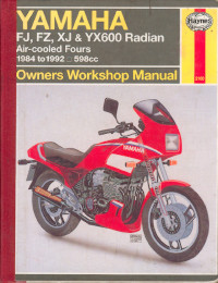
Руководство на английском языке по техническому обслуживанию и ремонту мотоциклов Yamaha моделей FJ600, FZ600, XJ600 и YX600 Radian.
- Издательство: Haynes Publishing
- Год издания: —
- Страниц: 200
- Формат: PDF
- Размер: 89,6 Mb
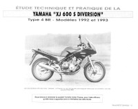
Руководство на французском языке по техническому обслуживанию и ремонту мотоциклов Yamaha XJ600S Diversion 1992-1993 годов выпуска.
- Издательство: —
- Год издания: —
- Страниц: 78
- Формат: JPG
- Размер: 36,7 Mb

Руководство на английском языке по техническому обслуживанию и ремонту мотоциклов Yamaha моделей XJ600S Diversion, Seca II 1992-1999 и XJ600N 1995-1999 годов выпуска.
- Издательство: Haynes Publishing
- Год издания: 2001
- Страниц: 162
- Формат: PDF
- Размер: 42,7 Mb
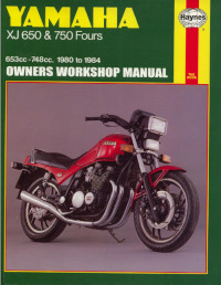
Руководство на английском языке по техническому обслуживанию и ремонту мотоциклов Yamaha моделей XJ650 и XJ750 Fours.
- Издательство: Haynes Publishing
- Год издания: 1994
- Страниц: 277
- Формат: PDF
- Размер: 124,8 Mb
Руководство на английском языке по ремонту мотоциклов Yamaha моделей XJ900S и XJ900SG 1995 года выпуска.
- Издательство: Yamaha Motor Co., Ltd.
- Год издания: —
- Страниц: 352
- Формат: PDF
- Размер: 102,4 Mb

- Manuals
- Brands
- Yamaha Manuals
- Motorcycle
- F DIVERSION XJ6F
- Owner’s manual
-
Contents
-
Table of Contents
-
Troubleshooting
-
Bookmarks
Quick Links
Read this manual carefully before operating this vehicle.
OWNER’S MANUAL
XJ6F
XJ6FA
1CW-28199-E3
Related Manuals for Yamaha F DIVERSION XJ6F
Summary of Contents for Yamaha F DIVERSION XJ6F
-
Page 1
Read this manual carefully before operating this vehicle. OWNER’S MANUAL XJ6F XJ6FA 1CW-28199-E3… -
Page 2
Read this manual carefully before operating this vehicle. This manual should stay with this vehicle if it is sold. YAMAHA MOTOR ELECTRONICS CO., LTD. 1450-6, Mori, Mori-machi, Shuchi-gun, Shizuoka-ken, 437-0292 Japan DECLARATION of CONFORMITY Company: YAMAHA MOTOR ELECTRONICS CO., LTD. Address: 1450-6, Mori, Mori-Machi, Shuchi-gun, Shizuoka-Ken, 437-0292 Japan Hereby declare that the product: Kind of equipment: IMMOBILIZER… -
Page 3
EAU10103 Welcome to the Yamaha world of motorcycling! As the owner of the XJ6F/XJ6FA, you are benefiting from Yamaha’s vast experience and newest technology regarding the design and manufacture of high-quality products, which have earned Yamaha a reputation for dependability. -
Page 4: Important Manual Information
IMPORTANT MANUAL INFORMATION EAU10134 Particularly important information is distinguished in this manual by the following notations: This is the safety alert symbol. It is used to alert you to potential personal injury hazards. Obey all safety messages that follow this symbol to avoid possible injury or death.
-
Page 5
IMPORTANT MANUAL INFORMATION EAU10201 XJ6F/XJ6FA OWNER’S MANUAL ©2013 by Yamaha Motor Co., Ltd. 1st edition, May 2013 All rights reserved. Any reprinting or unauthorized use without the written permission of Yamaha Motor Co., Ltd. is expressly prohibited. Printed in Japan. -
Page 6: Table Of Contents
TABLE OF CONTENTS SAFETY INFORMATION ….1-1 Adjusting the shock absorber Adjusting the engine idling assembly……..3-21 speed ……..6-19 DESCRIPTION ……..2-1 Sidestand ……..3-22 Checking the throttle grip free Left view ……… 2-1 Ignition circuit cut-off system ..3-22 play……….6-20 Right view……..
-
Page 7
TABLE OF CONTENTS Checking the front fork….6-33 Checking the steering ….6-34 Checking the wheel bearings ..6-34 Battery ………..6-34 Replacing the fuses…….6-36 Replacing the headlight bulb..6-38 Replacing the tail/brake light bulb ……….6-39 Replacing a turn signal light bulb ……….6-39 Replacing the license plate light bulb ……….6-40 Auxiliary light bulb ……6-41 Front wheel (for non-ABS… -
Page 8: Safety Information
SAFETY INFORMATION Never operate a motorcycle with- pears to be very effective in reduc- EAU1028B out proper training or instruction. ing the chance of this type of Take a training course. Beginners accident. Be a Responsible Owner should receive training from a cer- Therefore: As the vehicle’s owner, you are re- tified instructor.
-
Page 9
SAFETY INFORMATION Many accidents involve inexperi- • Always signal before turning or Protective Apparel enced operators. In fact, many op- changing lanes. Make sure that The majority of fatalities from motorcy- erators who have been involved in other motorists can see you. cle accidents are the result of head in- … -
Page 10
SAFETY INFORMATION Do not run engine outdoors where Avoid Carbon Monoxide Poisoning When loading within this weight limit, All engine exhaust contains carbon engine exhaust can be drawn into keep the following in mind: Cargo and accessory weight monoxide, a deadly gas. -
Page 11
Yamaha accessories, which are avail- performed to your vehicle that change lightweight as possible and able only from a Yamaha dealer, have any of the vehicle’s design or operation should be kept to a minimum. been designed, tested, and approved characteristics can put you and others •… -
Page 12
SAFETY INFORMATION Check that the fuel cock (if operator and may limit control ability, therefore, such accesso- equipped) is in the “OFF” position ries are not recommended. and that there are no fuel leaks. Use caution when adding electri- … -
Page 13: Description
DESCRIPTION EAU10411 Left view 1. Air filter element (page 6-18) 9. Engine oil filter cartridge (page 6-12) 2. Idle adjusting screw (page 6-19) 10.Engine oil drain bolt (page 6-12) 3. Seat lock (page 3-18) 4. Main fuse (page 6-36) 5. Fuse box (page 6-36) 6.
-
Page 14: Right View
DESCRIPTION EAU10421 Right view 1. Helmet holder (page 3-19) 9. Brake pedal (page 3-14) 2. Battery (page 6-34) 10.Rear brake light switch (page 6-25) 3. Rear brake fluid reservoir (page 6-26) 11.Shock absorber assembly spring preload adjusting ring (page 3-21) 4.
-
Page 15: Controls And Instruments
DESCRIPTION EAU10431 Controls and instruments 1. Clutch lever (page 3-13) 2. Left handlebar switches (page 3-11) 3. Main switch/steering lock (page 3-2) 4. Multi-function meter unit (page 3-8) 5. Front brake fluid reservoir (page 6-26) 6. Right handlebar switches (page 3-11) 7.
-
Page 16: Instrument And Control Functions
Do not expose any key to exces- cess, take the vehicle along with all three keys to a Yamaha dealer to have sively high temperatures. Do not place any key close to them re-registered. Do not use the key with the red bow for driving.
-
Page 17: Main Switch/Steering Lock
INSTRUMENT AND CONTROL FUNCTIONS Keep other immobilizer system EAU10473 EAU38531 Main switch/steering lock keys away from the main switch All electrical circuits are supplied with as they may cause signal inter- power; the meter lighting, taillight, li- ference. cense plate light and auxiliary light come on, and the engine can be start- ed.
-
Page 18
INSTRUMENT AND CONTROL FUNCTIONS To unlock the steering EAU10685 ECA11021 LOCK NOTICE The steering is locked, and all electrical Do not use the parking position for systems are off. The key can be re- an extended length of time, other- moved. -
Page 19: Indicator Lights And Warning Lights
2.5 seconds. If this occurs, 4. High beam indicator light “ ” to “ON”. The warning light should have a Yamaha dealer check the 5. Engine trouble warning light “ ” come on for a few seconds, and then vehicle.
-
Page 20
If the warning light does not come on initially when the key is turned to “ON”, or if the warning light remains on, have a Yamaha dealer check the electrical circuit. ECA10022 NOTICE Do not continue to operate the en- gine if it is overheating. -
Page 21
INSTRUMENT AND CONTROL FUNCTIONS Display Conditions What to do Under 40 °C Message “Lo” is displayed. OK. Go ahead with riding. (Under 104 °F) 40–116 °C Coolant temperature is dis- OK. Go ahead with riding. (104–242 °F) played. Stop the vehicle and allow it to idle until Coolant temperature flash- 117–134 °C the coolant temperature goes down. -
Page 22
If this oc- light will come on, but this is not a mal- The ABS may not work correctly. If any curs, have a Yamaha dealer check the function. of the above occurs, have a Yamaha self-diagnosis system. -
Page 23: Multi-Function Meter Unit
INSTRUMENT AND CONTROL FUNCTIONS multi-function meter unit Tachometer EAU46766 Multi-function meter unit equipped with the following: a speedometer a tachometer an odometer two tripmeters (which show the distance traveled since they were last set to zero) …
-
Page 24: Fuel Meter
INSTRUMENT AND CONTROL FUNCTIONS Clock 5. Push the “RESET” button to set mode “F-TRIP” and start counting the the minutes. distance traveled from that point. In 6. Push the “SELECT” button and that case, push the “SELECT” button then release it to start the clock. to switch the display between the vari- ous tripmeter and odometer modes in Odometer and tripmeter modes…
-
Page 25
ECA10022 NOTICE times, then go off for approximately 3 agnosis device for various electrical seconds. If this occurs, have a Yamaha circuits. Do not continue to operate the en- dealer check the electrical circuit. If a problem is detected in any of those gine if it is overheating. -
Page 26: Handlebar Switches
If a problem is detected in the immobi- key and both standard keys to a EAU1234E Handlebar switches lizer system circuits, the immobilizer Yamaha dealer and have the stan- system indicator light will flash and the dard keys re-registered. Left display will indicate an error code.
-
Page 27
INSTRUMENT AND CONTROL FUNCTIONS Right ter position. To cancel the turn signal EAU12734 Hazard switch “ ” lights, push the switch in after it has re- With the key in the “ON” or “ ” posi- turned to the center position. tion, use this switch to turn on the haz- ard lights (simultaneous flashing of all EAU12501… -
Page 28: Clutch Lever
INSTRUMENT AND CONTROL FUNCTIONS EAU12821 EAU12872 EAU26825 Clutch lever Shift pedal Brake lever The brake lever is located on the right side of the handlebar. To apply the front brake, pull the lever toward the throttle grip. 1. Clutch lever 1.
-
Page 29: Brake Pedal
EAU51801 Brake pedal ABS (for ABS models) The ABS performs a self-diagno- The Yamaha ABS (Anti-lock Brake sis test each time the vehicle first System) features a dual electronic con- starts off after the key is turned to trol system, which acts on the front and “ON”…
-
Page 30: Fuel Tank Cap
INSTRUMENT AND CONTROL FUNCTIONS wheel hubs may be damaged, re- EAU13075 Fuel tank cap sulting in improper performance of The fuel tank cap cannot be closed un- the ABS system. less the key is in the lock. In addition, the key cannot be removed if the cap is not properly closed and locked.
-
Page 31: Fuel
WARNING pump nozzle into the fuel tank filler Gasoline is poisonous and can Your Yamaha engine has been de- hole. Stop filling when the fuel cause injury or death. Handle gaso- signed to use regular unleaded gaso- reaches the bottom of the filler line with care.
-
Page 32: Fuel Tank Breather Hose And Overflow Hose
10% (E10). Gas- Do not park the vehicle near ohol containing methanol is possible fire hazards such as recommended by Yamaha because it grass or other materials that can cause damage to the fuel system easily burn. or vehicle performance problems.
-
Page 33: Seat
INSTRUMENT AND CONTROL FUNCTIONS ECA10702 EAU32981 Seat NOTICE Use only unleaded gasoline. The use To remove the seat of leaded gasoline will cause unre- 1. Insert the key into the seat lock, pairable damage to the catalytic and then turn it counterclockwise. converter.
-
Page 34: Helmet Holder
INSTRUMENT AND CONTROL FUNCTIONS EAU46752 EAU14454 Helmet holder Storage compartment 1. Helmet 2. Helmet holding cable 1. Helmet holder 1. Storage compartment 3. Helmet holder 2. Owner’s tool kit The storage compartment is located 3. Place the helmet on the right side 3.
-
Page 35: Handlebar Position
XJ6FA 180 kg (397 lb) for the ve- of two positions to suit the rider’s pref- can be folded forward for parking in hicle. erence. Have a Yamaha dealer adjust narrow spaces. Fold the mirrors back the position of the handlebar. to their original position before riding.
-
Page 36: Adjusting The Shock Absorber Assembly
Spring preload setting: sembly yourself. Take the shock the adjusting ring in direction (a). To Minimum (soft): absorber assembly to a Yamaha decrease the spring preload and there- dealer for any service. by soften the suspension, turn the ad- Standard: justing ring in direction (b).
-
Page 37: Sidestand
EAU15306 EAU44903 Sidestand Ignition circuit cut-off system Yamaha dealer repair it if it does not The sidestand is located on the left The ignition circuit cut-off system function properly. side of the frame. Raise the sidestand…
-
Page 38
”. stand during this inspection. • 3. Turn the key on. If a malfunction is noted, have a Yamaha 4. Shift the transmission into the neutral position. dealer check the system before riding. 5. Push the start switch. Does the engine start? With the engine still running: The neutral switch may not be working correctly. -
Page 39: For Your Safety — Pre-Operation Checks
• If necessary, add recommended coolant to specified level. 6-15 Coolant • Check cooling system for leakage. • Check operation. • If soft or spongy, have Yamaha dealer bleed hydraulic system. • Check brake pads for wear. Front brake • Replace if necessary. 6-26, 6-26 •…
-
Page 40
• Make sure that operation is smooth. • Check throttle grip free play. 6-20, 6-30 Throttle grip • If necessary, have Yamaha dealer adjust throttle grip free play and lubricate ca- ble and grip housing. • Make sure that operation is smooth. Control cables 6-30 •… -
Page 41
• Tighten if necessary. Instruments, lights, signals • Check operation. — and switches • Correct if necessary. • Check operation of ignition circuit cut-off system. Sidestand switch 3-22 • If system is not working correctly, have Yamaha dealer check vehicle. -
Page 42: Operation And Important Riding Points
a lean angle sensor to stop the en- The transmission is in the neutral understand, ask your Yamaha dealer. gine in case of a turnover. In this EWA10272 position.
-
Page 43: Shifting
The gear positions are shown in the il- neutral position. The neutral indi- lustration. cator light should come on. If not, ask a Yamaha dealer to check the To shift the transmission into the neu- electrical circuit. tral position, press the shift pedal down 3.
-
Page 44: Tips For Reducing Fuel Consumption
OPERATION AND IMPORTANT RIDING POINTS ECA10261 EAU16811 EAU16842 Tips for reducing fuel con- Engine break-in NOTICE sumption There is never a more important period Even with the transmission in in the life of your engine than the period Fuel consumption depends largely on the neutral position, do not between 0 and 1600 km (1000 mi).
-
Page 45: Parking
Yamaha dealer check the vehi- touch them and be burned. cle. Do not park on a slope or on soft…
-
Page 46: Periodic Maintenance And Adjustment
To avoid possible burns, let tivities incorrectly may increase brake components cool before your risk of injury or death during touching them. service or while using the vehicle. If you are not familiar with vehicle ser- vice, have a Yamaha dealer perform service.
-
Page 47: Owner’s Tool Kit
If you do not have the tools or experi- ence required for a particular job, have a Yamaha dealer perform it for you.
-
Page 48: Periodic Maintenance Chart For The Emission Control System
From 50000 km (30000 mi), repeat the maintenance intervals starting from 10000 km (6000 mi). Items marked with an asterisk should be performed by a Yamaha dealer as they require special tools, data and tech- nical skills.
-
Page 49: General Maintenance And Lubrication Chart
PERIODIC MAINTENANCE AND ADJUSTMENT EAU1770G General maintenance and lubrication chart ODOMETER READING ANNUAL ITEM CHECK OR MAINTENANCE JOB 1000 km 10000 km 20000 km 30000 km 40000 km CHECK (600 mi) (6000 mi) (12000 mi) (18000 mi) (24000 mi) √ Air filter element •…
-
Page 50
PERIODIC MAINTENANCE AND ADJUSTMENT ODOMETER READING ANNUAL ITEM CHECK OR MAINTENANCE JOB 1000 km 10000 km 20000 km 30000 km 40000 km CHECK (600 mi) (6000 mi) (12000 mi) (18000 mi) (24000 mi) • Check operation and for exces- √ √… -
Page 51
PERIODIC MAINTENANCE AND ADJUSTMENT ODOMETER READING ANNUAL ITEM CHECK OR MAINTENANCE JOB 1000 km 10000 km 20000 km 30000 km 40000 km CHECK (600 mi) (6000 mi) (12000 mi) (18000 mi) (24000 mi) • Check operation and for oil leak- √… -
Page 52
PERIODIC MAINTENANCE AND ADJUSTMENT EAU18681 Air filter • This model’s air filter is equipped with a disposable oil-coated paper element, which must not be cleaned with com- pressed air to avoid damaging it. • The air filter element needs to be replaced more frequently when riding in unusually wet or dusty areas. … -
Page 53: Removing And Installing Cowlings And Panels
PERIODIC MAINTENANCE AND ADJUSTMENT EAU18713 EAU55870 Removing and installing cowl- ings and panels Cowling A The cowlings and panels shown need to be removed to perform some of the To remove the cowling maintenance jobs described in this Remove the bolts, and then take the chapter.
-
Page 54
PERIODIC MAINTENANCE AND ADJUSTMENT 2. Remove the quick fastener and the bolts, and then take the cowl- ing off. 1. Turn signal light lead 3. Install cowling A. 2. Guide 3. Turn signal light lead coupler EAU56060 1. Cowling B To install a cowling 2. -
Page 55
PERIODIC MAINTENANCE AND ADJUSTMENT 1. Panel A 1. Panel B 3. Pull the panel backward to re- 2. Bolt 2. Quick fastener move it. 3. Quick fastener 3. Bolt 2. Slide the panel backward, and To install the panel then lift up the rear of the panel Place the panel in the original position, slightly. -
Page 56: Checking The Spark Plugs
Before installing a spark plug, the checked periodically, preferably by a spark plug gap should be measured Yamaha dealer. Since heat and depos- with a wire thickness gauge and, if its will cause any spark plug to slowly necessary, adjusted to specification.
-
Page 57: Engine Oil And Oil Filter Cartridge
PERIODIC MAINTENANCE AND ADJUSTMENT EAU47552 Engine oil and oil filter car- If a torque wrench is not available tridge when installing a spark plug, a good The engine oil level should be checked estimate of the correct torque is 1/4– before each ride.
-
Page 58
An oil filter wrench is available at a en the oil filler cap. Yamaha dealer. 6. Apply a thin coat of clean engine To change the engine oil (with or oil to the O-ring of the new oil filter without oil filter cartridge replace- cartridge. -
Page 59
8. Install the engine oil drain bolt and In order to prevent clutch slip- off and have a Yamaha dealer check its new gasket, and then tighten page (since the engine oil also the vehicle. -
Page 60: Coolant
PERIODIC MAINTENANCE AND ADJUSTMENT EAU20071 Coolant The coolant level should be checked before each ride. In addition, the cool- ant must be changed at the intervals specified in the periodic maintenance and lubrication chart. EAU50541 To check the coolant level 1.
-
Page 61
EAU50741 To change the coolant water has been added to the 1. Place the vehicle on the center- coolant, have a Yamaha dealer stand and let the engine cool if check the antifreeze content of necessary. the coolant as soon as possible, 2. -
Page 62
16. Remove the radiator cap to check the vehicle for coolant leakage. If Tightening torque: the coolant level in the radiator. If coolant is leaking, have a Yamaha Coolant drain bolt: necessary, add sufficient coolant dealer check the cooling system. -
Page 63: Replacing The Air Filter Element
1. Fuel tank bolt they are not pinched. If any hose 1. Air filter element 4. Remove the air filter case cover by is damaged, have a Yamaha 2. Air intake manifold removing the screws. NOTICE: dealer replace the hose before…
-
Page 64: Adjusting The Engine Idling Speed
If the specified idling speed cannot be follows at the intervals specified in the obtained as described above, have a periodic maintenance and lubrication Yamaha dealer make the adjustment. chart. The engine should be warm before making this adjustment. Check the engine idling speed and, if necessary, adjust it to specification by turning the idle adjusting screw.
-
Page 65: Checking The Throttle Grip Free Play
Therefore, it must be adjusted by a Yamaha dealer is essential to maintain the tires in good at the intervals specified in the periodic condition at all times and replace them maintenance and lubrication chart.
-
Page 66
* Total weight of rider, passenger, car- or glass fragments in it, or if the side- in” for it to develop its optimal go and accessories wall is cracked, have a Yamaha dealer characteristics. replace the tire immediately. Minimum tire tread depth (front and rear): 1.6 mm (0.06 in) -
Page 67
WARNING ed below have been approved for this Tires age, even if they have not been model by Yamaha Motor Co., Ltd. This motorcycle is fitted with super- used or have only been used occasion- high-speed tires. Note the following ally. -
Page 68: Cast Wheels
If any damage is found, have conditions. a Yamaha dealer replace the wheel. Do not attempt even the smallest repair to the wheel. A de- 1. Clutch lever free play adjusting bolt formed or cracked wheel must be 2.
-
Page 69: Checking The Brake Lever Free Play
There should be no free play at the adjusting nut in direction (a). To brake lever end. If there is free play, decrease the clutch lever free have a Yamaha dealer inspect the play, turn the adjusting nut in di- brake system. rection (b).
-
Page 70: Brake Light Switches
The brake light, which is activated by the brake pedal and brake lever, should come on just before braking takes effect. If necessary, have a Yamaha dealer adjust the brake light switches. 1. Rear brake light switch 2. Rear brake light switch adjusting nut…
-
Page 71: Checking The Front And Rear Brake Pads
EAU22393 EAU43113 Checking the front and rear Checking the brake fluid level peared, have a Yamaha dealer replace brake pads Before riding, check that the brake fluid the brake pads as a set. is above the minimum level mark.
-
Page 72
If the brake Use only the specified brake flu- fluid level goes down suddenly, have a id; otherwise, the rubber seals Yamaha dealer check the cause before may deteriorate, causing leak- further riding. age. Refill with the same type of brake fluid. -
Page 73: Changing The Brake Fluid
EAU53951 Changing the brake fluid Drive chain slack To adjust the drive chain slack Consult a Yamaha dealer before ad- Have a Yamaha dealer change the The drive chain slack should be justing the drive chain slack. brake fluid at the intervals specified in checked before each ride and adjusted 1.
-
Page 74: Cleaning And Lubricating The Drive Chain
PERIODIC MAINTENANCE AND ADJUSTMENT EAU23026 Cleaning and lubricating the Using the alignment marks on each drive chain drive chain puller, make sure that both The drive chain must be cleaned and chain pullers are in the same position lubricated at the intervals specified in for proper wheel alignment.
-
Page 75: Checking And Lubricating The Cables
Yamaha dealer at the intervals cated if necessary. If a cable is specified in the periodic maintenance damaged or does not move smoothly, chart.
-
Page 76: Checking And Lubricating The Brake And Shift Pedals
PERIODIC MAINTENANCE AND ADJUSTMENT EAU44274 EAU23144 Recommended lubricant: Checking and lubricating the Checking and lubricating the Lithium-soap-based grease brake and shift pedals brake and clutch levers The operation of the brake and shift The operation of the brake and clutch pedals should be checked before each levers should be checked before each ride, and the pedal pivots should be lu-…
-
Page 77: Checking And Lubricating The Centerstand And Sidestand
EWA10742 WARNING If the centerstand or sidestand does not move up and down smoothly, have a Yamaha dealer check or re- pair it. Otherwise, the centerstand or sidestand could contact the ground and distract the operator, resulting in a possible loss of control.
-
Page 78: Lubricating The Swingarm Pivots
The swingarm pivots must be lubricat- face and hold it in an upright posi- fork does not operate smoothly, ed by a Yamaha dealer at the intervals tion. WARNING! To avoid injury, have a Yamaha dealer check or re- specified in the periodic maintenance securely support the vehicle so pair it.
-
Page 79: Checking The Steering
If any free (See page 3-18.) hub or if the wheel does not turn play can be felt, have a Yamaha This model is equipped with a VRLA smoothly, have a Yamaha dealer dealer check or repair the steer- (Valve Regulated Lead Acid) battery.
-
Page 80
To charge the battery charge it if necessary. Have a Yamaha dealer charge the bat- 3. Fully charge the battery before in- stallation. NOTICE: When install- tery as soon as possible if it seems to have discharged. -
Page 81: Replacing The Fuses
PERIODIC MAINTENANCE AND ADJUSTMENT XJ6F XJ6FA EAU47173 Replacing the fuses The main fuse and the fuse boxes, which contain the fuses for the individ- ual circuits, are located under the seat. (See page 3-18.) To access the main fuse, remove the starter relay cover as shown.
-
Page 82
PERIODIC MAINTENANCE AND ADJUSTMENT XJ6FA rating than recommended to 4. If the fuse immediately blows again, have a Yamaha dealer avoid causing extensive dam- age to the electrical system and check the electrical system. possibly a fire. [EWA15132] Specified fuses: Main fuse: 30.0 A… -
Page 83: Replacing The Headlight Bulb
Headlight lens 6. Install the cowlings. Do not affix any type of tinted 7. Have a Yamaha dealer adjust the film or stickers to the headlight headlight beam if necessary. lens. Do not use a headlight bulb of a wattage higher than specified.
-
Page 84: Replacing The Tail/Brake Light Bulb
PERIODIC MAINTENANCE AND ADJUSTMENT EAU47022 EAU24205 Replacing the tail/brake light Replacing a turn signal light bulb bulb 1. Remove the seat. (See page 3-18.) 1. Remove the turn signal light lens 2. Remove the tail/brake light bulb by removing the screw. socket (together with the bulb) by turning it counterclockwise.
-
Page 85: Replacing The License Plate Light Bulb
PERIODIC MAINTENANCE AND ADJUSTMENT EAU24314 Replacing the license plate light bulb 1. Remove the license plate light unit by removing the screws. 1. Turn signal light bulb 1. License plate light bulb socket 2. License plate light bulb 3. Insert a new bulb into the socket, 3.
-
Page 86: Auxiliary Light Bulb
EAU44792 Auxiliary light bulb Front wheel (for non-ABS models) EWA14841 WARNING For the ABS model, have a Yamaha dealer remove and install the wheel. EAU56280 1. Front wheel axle pinch bolt 2. Wheel axle To remove the front wheel 1. Auxiliary light bulb 3.
-
Page 87: Rear Wheel (For Non-Abs Models)
EWA14841 sidestand down. WARNING 5. Tighten the wheel axle, the front For the ABS model, have a Yamaha wheel axle pinch bolt and the dealer remove and install the wheel. brake caliper bolts to the specified torques.
-
Page 88
PERIODIC MAINTENANCE AND ADJUSTMENT To install the rear wheel 1. Install the wheel and the brake cal- The drive chain does not need to be iper bracket by inserting the wheel disassembled in order to remove and axle from the right-hand side. install the rear wheel. -
Page 89: Troubleshooting
Axle nut: 90 Nm (9.0 m·kgf, 65 ft·lbf) self. However, should your motorcycle Locknut: require any repair, take it to a Yamaha 16 Nm (1.6 m·kgf, 12 ft·lbf) dealer, whose skilled technicians have the necessary tools, experience, and know-how to service the motorcycle properly.
-
Page 90: Troubleshooting Charts
Remove the spark plugs and check the electrodes. The engine does not start. Have a Yamaha dealer check the vehicle. Check the compression. 4. Compression The engine does not start. There is compression.
-
Page 91
Start the engine. If the engine overheats again, have a The coolant level Yamaha dealer check and repair the cooling system. is OK. If coolant is not available, tap water can be temporarily used instead, provided that it is changed to the recommended cool- ant as soon as possible. -
Page 92: Motorcycle Care And Storage
Some models are equipped with matte colored finished parts. Be ble. Rust and corrosion can develop Cleaning sure to consult a Yamaha dealer for even if high-quality components are ECA10773 NOTICE used. A rusty exhaust pipe may go un-…
-
Page 93
For additional hoses and vents. during winter are extremely corrosive For motorcycles equipped with cleaning, use Yamaha Windshield in combination with water, carry out a windshield: Do not use strong Cleaner or another high-quality wind- the following steps after each ride in cleaners or hard sponges as shield cleaner. -
Page 94
MOTORCYCLE CARE AND STORAGE windshield which does not affect your EWA11132 WARNING visibility and which cannot be easily Consult a Yamaha dealer for ad- recognized. Contaminants on the brakes or tires vice on what products to use. can cause loss of control. -
Page 95: Storage
MOTORCYCLE CARE AND STORAGE 2. Fill up the fuel tank and add fuel e. Remove the spark plug caps EAU26183 Storage stabilizer (if available) to prevent from the spark plugs, and then the fuel tank from rusting and the install the spark plugs and the Short-term fuel from deteriorating.
-
Page 96
MOTORCYCLE CARE AND STORAGE Make any necessary repairs before storing the motorcycle. -
Page 97: Specifications
SPECIFICATIONS Dimensions: Engine oil: Fuel: Overall length: Recommended brand: Recommended fuel: 2120 mm (83.5 in) YAMALUBE Regular unleaded gasoline (Gasohol (E10) Overall width: Type: acceptable) 770 mm (30.3 in) SAE 10W-30, 10W-40, 10W-50, 15W-40, Fuel tank capacity: Overall height: 20W-40 or 20W-50 17.3 L (4.57 US gal, 3.81 Imp.gal) 1185 mm (46.7 in) Fuel reserve amount:…
-
Page 98
SPECIFICATIONS Final drive: Manufacturer/model: High-speed riding: Chain BRIDGESTONE/BT021 Front: Secondary reduction ratio: Manufacturer/model: 225 kPa (2.25 kgf/cm², 33 psi) 2.875 (46/16) DUNLOP/ROADSMART Rear: Transmission type: Rear tire: 250 kPa (2.50 kgf/cm², 36 psi) Constant mesh 6-speed Front wheel: Type: Operation: Tubeless Wheel type: Left foot operation… -
Page 99
SPECIFICATIONS Wheel travel: License plate light: Fuel injection system fuse: 12 V, 5.0 W × 1 130.0 mm (5.12 in) 10.0 A Rear suspension: Meter lighting: ABS control unit fuse: XJ6FA 7.5 A Type: Neutral indicator light: ABS motor fuse: Swingarm XJ6FA 30.0 A Spring/shock absorber type:… -
Page 100: Consumer Information
Record the vehicle identification num- ber and model label information in the spaces provided below for assistance when ordering spare parts from a Yamaha dealer or for reference in case the vehicle is stolen. VEHICLE IDENTIFICATION NUMBER: 1. Vehicle identification number 1.
-
Page 101
INDEX Maintenance, emission control system ……….6-3 ABS (for ABS models) ……3-14 Engine break-in ……..5-3 Matte color, caution…….. 7-1 ABS warning light (for ABS models) ..3-7 Engine idling speed……6-19 Model label ……….9-1 Air filter element, replacing….6-18 Engine oil and oil filter cartridge… -
Page 102
INDEX Throttle grip free play, checking …6-20 Tires …………6-20 Tool kit …………6-2 Troubleshooting ……..6-44 Troubleshooting charts……6-45 Turn signal indicator light …….3-4 Turn signal light bulb, replacing….6-39 Turn signal switch ………3-12 Valve clearance……..6-20 Vehicle identification number ….9-1 Wheel bearings, checking…..6-34 Wheel, front (for non-ABS models) ..6-41 Wheel, rear (for non-ABS models) ..6-42 Wheels ……….6-23… -
Page 104
Original instructions PRINTED ON RECYCLED PAPER PRINTED IN JAPAN 2013.06-0.3×1 CR…