Contents
2
Introduction
4
Your Vauxhall/Opel Zafira Manual
4
Project Vehicles
4
Acknowledgements
4
Safety First
5
General Hazards
5
Special Hazards
5
Roadside Repairs
6
If Your Car Won’t Start and the Starter Motor Doesn’t Turn
6
If Your Car Won’t Start Even Though the Starter Motor Turns as Normal
6
Jump Starting
7
Wheel Changing
8
Using the Puncture Repair Kit
9
Weekly Checks
10
Identifying Leaks
10
Towing
10
Sump Oil
10
Underbonnet Check Points
11
1.6 Litre Petrol
11
1.8 Litre Petrol
11
2.2 Litre Petrol
12
1.9 Litre Diesel
12
Engine Oil Level
13
Coolant Level
13
Before You Start
13
Car Care
13
Tyre Condition and Pressure
14
Tyre Tread Wear Patterns
14
Shoulder Wear
14
Centre Wear
14
Brake Fluid Level
15
Screen Washer Fluid Level
15
Wiper Blades
16
Battery
16
Electrical Systems
17
Lubricants, Fluids and Tyre Pressures
18
Routine Maintenance and Servicing — Petrol Models
19
Degrees of Difficulty
19
Table of Contents
19
Servicing Specifications — Petrol Models
20
Maintenance Schedule — Petrol Models
21
Component Location — Petrol Models
22
Underbonnet View of a 1.6 Litre Model
22
Underbonnet View of a 1.8 Litre Model
22
Underbonnet View of a 2.2 Litre Model
23
Front Underbody View
23
Rear Underbody View
24
Maintenance Procedures
24
General Information
24
Regular Maintenance
24
Every 10 000 Miles or 6 Months
25
Removing the Oil Filler Cup
25
Using an Oil Filler Removal Tool to Slacken the Canister-Type Filter
25
Engine Oil and Filter Renewal
25
Every 20 000 Miles or 12 Months
26
Unscrew the Filter Cup
26
Withdraw Together with the Element
26
Separate the Element from the Cap
26
Power Steering Fluid Level Check
27
Clutch Hydraulic Fluid Level Check
27
Brake Pad and Disk Check
27
Brake Fluid Pipe and Hose Check
27
Front Suspension and Steering Check
28
Driveshaft Check
28
Exhaust System Check
28
Rear Suspension Check
28
Bodywork and Underbody Condition Check
29
Roadwheel Bolt Tightness Check
29
Electrical Systems Check
29
Road Test
29
Every 40 000 Miles or 2 Years
30
Pollen Filter Renewal
30
Auxiliary Drivebelt Condition Check
30
Checking
30
Every 2 Years, Regardless of Mileage
31
Handbrake Operation and Adjustment Check
31
Headlight Beam Alignment Check
31
Hydraulic Fluid Renewal
31
Coolant Renewal
32
Exhaust Emission Check
32
Cooling System Draining
32
Cooling System Flushing
32
Every 40 000 Miles or 4 Years
33
Air Claner Element Renewal
33
Spark Plug Renewal
33
Disconnect Wiring Connector from Inlet Air Temperature Sensor
33
Every 100 000 Miles or 10 Years
34
Measuring a Spark Plug Electrode Gap Using a Feeler Blade
34
Measuring a Spark Plug Electrode Gap Using a Wire Gauge
34
Routine Maintenance and Servicing — Diesel Models
35
Coolant Renewal
35
Driveshaft Check
35
Handbrake Operation and Adjustment Check
35
Hinge and Lock Lubrication
35
Hose and Fluid Leak Check
35
Pollen Filter Renewal
35
Power Steering Fluid Level Check
35
Rear Suspension Check
35
Servicing Specifications — Diesel Models
36
Maintenance Schedule — Diesel Models
37
Component Location — Diesel Models
38
Underbonnet View of an SOHC Engine Model
38
Primary Operations
39
Secondary Operations
39
Regular Maintenance
39
Maintenance Procedures — Diesel Models
40
Engine Oil Drain Plug Location
40
Unscrew the Filter Cap and Withdraw It Together with the Element
40
Remove the Two O-Ring Seals
40
Hose and Fluid Leak Check
41
Fuel Filter Water Draining
41
Power Steering Fluid Reservoir Filler Cap
41
The Fluid Level Should be up to the MAX Mark on the Dipstick
41
Brake Pad and Disc Check
42
Check for Wear in the Hub Bearings by Grasping the Wheel
42
Check the Condition of the Driveshaft Gaiters and the Retaining Clips
42
Hinge and Lock Lubrication
43
Bodywork Damage/Corrosion Check
43
Corrosion Protection Check
43
Exhaust Mountings
43
Service Interval Indicator Reset
44
Fuel Filter Renewal
44
Instruments and Electrical Equipment
44
Steering and Suspension
44
Using Home-Made Tool to Slacken Filter Housing Cover Retaining Ring
45
Unscrew and Remove the Cover Retaining Ring
45
Lift the Cover Together with the Filter Element
45
Recover the 0-Ring Seal
45
Hanbrake Operation and Adjustment Check
46
Turn Drivebelt Tensioner Using Spanner on the Pulley Centre Bolt
46
Lock Tensioner by Inserting a Drill Bit through Hole on Tensioner
46
Handbrake Cable Adjuster Nut
46
Remote Control Battery Renewal
47
Hydraulic Fluid Renewall
47
Radiator Flushing
47
Engine Flushing
47
Air Cleaner Element Renewal
48
Cooling System Filling
48
Antifreeze Mixture
48
Open Bleed Screw in Coolant Pipe above the Exhaust Manifold
48
Every 50 000 Miles or 6 Years
49
Every 80 000 Miles or 10 Years
49
1.6 and 1.8 Litre Petrol Engine In-Car Repair Procedures
51
Specifications
51
Compression Test — General Information
53
Top Dead Centre for no 1 Piston — Locating
53
How to Use the Chapter
53
Engine Description
53
Camshaft Cover — Removal and Refitting
54
Align the Camshaft Sprocket Timing Marks on 1.6 Litre Engines
54
Notch on Crankshaft Pulley Rim with Mark at Base of Timing Belt Cover
54
Locate Rubber Seal into Grooves of Camshaft Cover
54
Crankstlaft Pulley- Removal and Refitting
55
Timing Belt Covers — Removal and Refitting
55
Upper Cover
55
Lower Cover
55
Timingt Belt — Removal and Refitting
56
Centre Cover (1.8 Litre Engines)
56
Rear Cover
56
Auxiliary Drivebelt Tensioner Retaining Bolt
56
Timing Belt Sprockets, Tensioner and Idler Pulley
57
Camshaft Sprockets
57
Insert Tool into Slots on End of Camshafts to Lock Camshafts
57
Camshaft Sprocket Closure Bolts
57
VVT Oil Control Valves
58
Camshaft Oil Seals
58
Valve Clearances
58
Crankshaft Sprocket
58
Camshaft and Followers
59
Using Feeler Blades, Measure Intake Valve Clearances
59
Camshaft Bearing Cap Numbering Sequence
59
Camshaft Bearing Cap Numbers
59
Use a Valve Lapping Tool to Remove the Cam Followers
60
Apply a Smear of Sealant to the Right-Hand Bearing Caps
60
Camshaft Bearing Cap Tightening Sequence
60
Camshaft Bearing Support Retaining Bolts
60
Cylinder Head
61
Preparation for Refitting
62
Refitting
62
Cylinder Head Bolt Loosening Sequence
62
Cylinder Head Bolt Tightening Sequence
62
Sump
63
Oil Pump
63
Tighten Cylinder Head Bolts to Specified Stage 1 Torque Setting
63
Remove Securing Screws and Withdraw Oil Pump Cover from Rear Housing
63
Unscrew the Oil Pressure Relief Valve Cap
64
Withdraw the Spring
64
Check Oil Pump Rotor Endfloat Using a Straight-Edge and Feeler Gauge
64
Oil Filler Housing
65
Crankshaft Oil Seals
65
Flywheel
65
Right-Hand
65
Inspection
66
Renewal
66
Left-Hand Mounting
66
Front Mounting/Torque Link
66
Rear Mounting/Torque Link
67
Rear Engine Mounting/Torque Link Retaining Bolts and Nut
67
2.2 Litre Petrol Engine In-Car Repair Procedures
69
Valve Timing
71
Operations with Engine in Car
71
Vauxhall/Opel Camshaft Locking Tool
71
Camshaft Cover
72
Crankshaft Pulley/Vibration Damper
72
Crankshaft Pulley and Timing Chain Cover Timing Marks
72
Locking Camshaft Sprockets in Position Using Vauxhall/Opel Tool
72
Timing Chain Cover
73
Turn Pulley until Flat on Centre Hub Locates with Oil Pump Drive
73
Fit a New Securing Bolt to the Pulley
73
Tighten Crankshaft Pulley Whilst Preventing Pulley Rotation
73
Timing Chain Tensioners
74
Camshaft Chain Tensioner
74
Carefully Lever Old Crankshaft Oil Seal out of Cover
74
Using a Suitable Drift Tap in the New Oil Seal
74
Timing Chains and Sprockets
75
Balance Shaft Chain Tensioner
75
Chain Tensioner and Guide Rails
75
Turn Inner Piston Screw Clockwise until It Locks in Position
75
Camshaft Chain and Sprockets
76
Balance Shaft Chain and Sprockets
76
Align Silver Link with Triangular Timing Mark on Exhaust Sprocket
76
Copper-Coloured Link with Diamond Timing Mark on Intake Sprocket
76
Undo the Retaining Bolts and Remove the Tension Rail and Guide Rails
77
Using a Drift to Lock the Balance Shaft Sprocket
77
Refit the Timing Chain Crankshaft Sprocket
77
Turning the Camshaft Slightly Using an Open-Ended Spanner
77
Use New Retaining Bolts When Refitting the Sliding Rail
78
Refit Balance Shaft Crankshaft Sprocket
78
Refit the Balance Shaft Sprockets Using New Securing Bolts
78
The Arrow Points Upwards on the Intake Sprocket
78
Alignment Marks Made on Camshaft Sprockets for Refitting
79
Use Container Used to Keep Followers and Hydraulic Tappets in Order
79
Keep Hydraulic Tappets in Labelled Containers with Clean Engine Oil
79
Lubricate Tappets with Clean Engine Oil before Refitting
79
Apply Silicone Sealing Compound Thinly to Surface Areas Arrowed
80
Refitting no 11 Cap to Flywheel/Driveplate End of Intake Camshaft
80
Refit New Retaining Bolts to the Camshaft Sprockets
80
Remove Two Coolant Hoses from Front of Cylinder Head
80
Using a Tap to Clean out the Threads in the Cylinder Block
81
Check Dowels Are in Position to Locate Cylinder Head Gasket
81
Ensuring Gasket Is Fitted with Its OBEN/TOP Marking Uppermost
81
Tightening Cylinder Head down through Its Stages, Using an Angle Gauge
81
Fit Four New Retaining Bolts to Timing Chain End Cylinder Head
82
Two of Bolts Are Inside Timing Chain Housing
82
Undo Two Sump to Transmission Bolts and also Sump-To-Lower Cylinder
82
Apply Continuous Bead of Silicone Sealer Around Sump
82
Balance Shaft
83
Undo Retaining Screws and Remove the Pump Cover Plate
83
Removing the Inner and Outer Rotors
83
Using a Feeler Blade to Check Inner-To-Outer Rotor Clearance
83
Flywheel/Driveplate
84
Manual Transmission Models
84
Automatic Transmission Models
84
Undo the Retaining Bolt
84
1.9 Litre SOHC Diesel Engine In-Car Repair Procedures
87
Compression Test
89
Leakdown Test
89
Open the Cover on the Fuse/Relay Box
89
Remove the Fuel Pump Relay
89
Top Dead Centre for no 1 Piston
90
Release the Hose Support Clip
90
Lift off the Plastic Cover over the Top of the Engine
90
Undo Central Bolt and Remove Auxiliary Drivebelt Tensioner Assembly
90
Valve Timing
91
Screw Fastening Stud of Special Tool into Oil Pump Housing
91
Position Ring of Tool Attached to Fastening Stud/Crankshaft Sprocket
91
Undo Retaining Bolt to Release Vacuum Lines from Camshaft Cover
91
Timing Belt
92
Move Leak-Off Hose Assembly Rearward, then Lift Camshaft Cover
92
Fit the Seal to the Camshaft Cover Groove
92
Crankshaft Pulley/Vibration Damper Retaining Bolts
92
Camshaft Sprocket
93
Using Screwdriver Resting on Pivot Bolt, Move Adjusting Lever
93
Tensioner Pointer Is Aligned with the Mark on the Backplate
93
High-Pressure Fuel Pump Sprocket
94
Tensioner Assembly
94
Remove the Bolt and Washer
94
Slide Sprocket off End of the Crankshaft
94
Camshaft Oil Seal
95
Idler Pulley
95
Slacken/Remove Retaining and Remove Timing Belt Tensioner Assembly
95
The Slot on Tensioner Backplate Must Locate over Peg on Engine Bracket
95
Thickness of each Shim Should be Stamped on One of Its Surfaces
96
Camshaft Bearing Cap Retaining Bolts
96
Carefully Release Oil Pipe from Its Location in the Cylinder Head
96
Undo Support Bracket Bolts, Release Retaining Clips
97
Cylinder Head Gasket Thickness Identification Hole
97
Using Dial Test Indicator to Measure Piston Protrusion
98
Place New Gasket in Position with Words ALTO/TOP Uppermost
98
Intermediate Shaft Bearing Housing Support Bracket Retaining Bolts
98
Air Conditioning Compressor Mounting Bracket Retaining Bolts
99
Removing Oil Baffle Plate from Inside the Sump
99
Renew Pick-Up/Strainer Sealing Ring Prior to Refitting
99
Apply Continuous Bead of Silicone Sealing Compound to Sump Flange
99
Oil Filter Housing
100
Oil Pump Housing Retaining Bolts
100
Undo Retaining Screws and Lift off Oil Pump Cover
100
Oil Pump Inner and Outer Rotor Identification Dots
100
Oil Filter Housing Retaining Bolts
101
Fit New Sealing Ring to Oil Filter Housing Supply Channel
101
Screw in Self-Tapping Screw and Pull on Screw with Pliers
101
Using Socket as Tubular Drift to Fit the New Oil Seal
101
Flywheel/Drive Plate
102
Engine/Transmission Mounting
102
Fitting New Oil Seal Housing, with Integral Oil Seal, over Crankshaft
102
After Fitting, Remove Protector Sleeve from the Housing
102
Unscrew Two Rear Mounting/ Torque Link Retaining Bolts
103
Right-Hand Mounting Retaining Bolts
103
Left-Hand Mounting Bracket-To-Transmission Bracket Retaining Bolts
103
Left-Hand Mounting-To-Body Retaining Bolts
103
1.9 Litre DOHC Diesel Engine In-Car Repair Procedures
105
Vauxhall/Opel Special Tool Is Required to Set TDC Position
108
Vauxhall/Opel Special Tool to Set the Camshaft Position
108
Undo Central Mounting Bolt and Remove Drivebelt Tensioner Assembly
108
Undo Retaining Bolts and Remove Right-Hand Engine Mounting
108
Positioning Ring of Tool Attached to Fastening Stud
109
Upper Timing Belt Cover Retaining Bolts
110
Undo Bolt and Remove Auxiliary Drivebelt Idler Pulley
110
Undo the Two Lower Bolts
110
Remove the Engine Bracket from the Engine
110
Slide the Sprocket off the End of the Crankshaft
112
Engage Holding Tool with Holes in Fuel Pump Sprocket
112
Use Suitable Puller to Release Fuel Pump Sprocket Taper
112
Once Taper Releases, Withdraw the Sprocket
112
Camshaft Housing
113
Slot on Tensioner Backplate Must Locate over Peg on Engine Bracket
113
Slacken and Remove Retaining Bolt and Remove Idler Pulley from Engine
113
Disconnect Wiring Connectors at Fuel Injectors
113
Camshaft
114
Disconnect Two Vacuum Hoses from Vacuum Pipe Assembly
114
Undo Two Retaining Bolts and Move Pipe Assembly to One Side
114
Release Retaining Clips and Remove the Charge Air Hose
114
Undo Three Retaining Bolts and Remove the Oil Filler Housing
115
Slacken Intake Camshaft Drive Gear Retaining Bolt
115
Exhaust Camshaft Drive Gear Retaining Bolt
115
Unscrew and Remove Two Previously-Slackened Retaining Bolts
115
Camshaft Followers and Hydraulic Tappets
116
Refit Camshaft Positioning Tool to Valve Timing Checking Hole
116
Unscrew Closure Bolt from Intake Camshaft Side of Camshaft Housing
116
Fit Camshaft Positioning Tool for the Intake Camshaft
116
Withdraw each Camshaft Follower
117
Hydraulic Tappet in Turn, and Place Them in Their Respective Container
117
Clip the Follower Back Onto the Tappet
117
Refit Tappet to Its Original Bore
117
Undo the Retaining Screws and Lift the Oil Pump Cover
120
Unscrew the Oil Pressure Relief Valve Bolt
120
Prime Oil Pump by Filling It with Clean Engine Oil
121
Bend down Tabs on Edge of Gasket to Retain It on Oil Pump Housing
121
Engine Removal and Overhaul Procedures
123
Engine Overhaul
127
Engine Removal
127
Engine and Transmission Unit
127
Petrol Engine Models
128
Diesel Engine Models
128
All Models
128
Disconnect Two Positive Cables from the Junction Box Terminals
128
Unscrew Nut/Remove Bolt Securing Steering Column Intermediate Shaft
129
Prise out Clip Securing Clutch Hydraulic Hose to End Fitting
129
Detach the Hose from the End Fitting
129
Engine Mounting Bracket-To-Engine Bracket Retaining Bolt
129
Cylinder Head and Valves
131
Using Valve Spring Compressor, Compress Valve Spring
131
Extract Two Split Collets by Hooking Them out Using Small Screwdriver
131
Remove the Valve Spring Cap
131
Valve Components
132
Straight-Edge and Feeler Gauge to Check Cylinder Head Distortion
132
Using a Micrometer to Measure Valve Stem Diameter
132
Grinding-In a Valve
132
Pistons/Connecting Rods
133
Refit the Valve Spring and Fit the Spring Cap
133
Compress Valve and Locate Collets in Recess on the Valve Stem
133
Check Crankshaft Endfloat Using a Dial Gauge
133
Cylinder Block
134
Main Bearing Cap Identification Marks
134
Lug at Base of Cap Is Used to Identify Intake Manifold Side
134
Unscrew Retaining Bolts and Remove Piston Oil Spray Nozzles
134
Using a Feeler Blade to Remove a Piston Ring
135
Main and Big-End Bearings
136
Piston Rings
136
Typical Bearing Failures
136
Measuring a Piston Ring End Gap Using a Feeler Gauge
137
Fitting the Oil Control Spreader Ring
137
Fitting a Main Bearing Shell to the Cylinder Block
137
Liberally Lubricate each Bearing Shell in Cylinder Block
137
Fill Side Grooves of no 5 Bearing Cap with Sealant
138
Tighten Bolts to Specified Stage 1 Torque Setting
138
Apply Continuous Bead of Sealant to Groove in Cylinder Block
138
Tightening Cylinder Block Lower Casing Bolts through Specified Angles
138
Piston/Connecting Rods
139
Press Bearing Shells into Connecting Rods and Caps
139
Piston Ring End Gap Positions
139
Ensure Piston Ring End Gaps Are Correctly Spaced, Fit Ring Compressor
139
Cut-Out on Piston Skirt Must be on same Side as Oil Spray Jet
140
Cooling, Heating and Air Conditioning Systems
141
General Information and Precautions
142
Cooling System Hoses
142
Radiator
142
Insert Drill Bit through Holes Provided on Radiator Brackets
143
Condenser Right-Hand Upper Retaining Bolt
143
Undo Two Bolts each Side
143
Remove Radiator Mounting Brackets, Noting Their Orientation
143
Thermostat
144
Removing Thermostat Housing Cover
144
Removing the Thermostat from the Housing
144
Disconnect Charge Air Hose from Throttle Housing
144
Electric Cooling Fan
145
Coolant Temperature Sensor
145
Undo Bolt Securing Fan Motor Resistor to Housing
145
Undo Three Bolts and Remove Motor from the Housing
145
Coolant Pump
146
Thermostat Housing Retaining Bolts
146
Removing Coolant Pipe from Pump Housing
146
Coolant Pump Drive Sprocket Access Cover
146
Unscrew the Rear Bolts
147
Withdraw Coolant Pump from Timing Housing
147
Undo Coolant Pump Retaining Bolts
147
Remove Pump from Cylinder Head
147
Heating and Ventilation System
148
Heater/Ventilation System Components
148
Heater Blower Motor
148
Heater Blower Motor Resistor
148
Mixed Air Valve Servo Motor
149
Heater Matrix
149
Heater Control Assembly
149
Air Distribution Housing
149
Air Conditioning System
150
Air Conditioning System Components
150
Air Conditioning Service Ports
150
Compressor
150
Evaporator
151
Auxiliary Cooling Fan
151
Condenser
151
Unclip the Relays from the Auxiliary Cooling Fan Housing
151
Fuel and Exhaust Systems — Petrol Engines
153
Air Cleaner Assembly and Intake Ducts
155
Accelerator Pedal/Position Sensor
155
Unleaded Petrol
155
Disconnect Wiring Connector from Side of Inlet Air Temperature Sensor
155
Fuel Injection System
156
Fuel Gauge Sender Unit
156
Fuel Pressure Connection Valve on Fuel Rail
156
Fuel Pressure Connection Valve on High-Pressure Fuel Pump
156
Fuel Supply Pump
157
Fuel Tank
157
Insert Removal Tools down through Slots on Side of In-Tank Module
157
Push the Tools down into the Slots
157
Throttle Housing
158
Disconnect Fuel and Vapour Lines at Underbody Quick-Release Connectors
158
Unclip Handbrake Cables from Fuel Tank Retaining Straps
158
Undo Bolt Securing Filler Pipe to the Underbody
158
Fuel Injection Systems
159
Fuel Injection System Components
159
Throttle Housing Retaining Bolts
159
Unclip and Remove Ashtray Insert
159
Multec-S Injection System Components
160
Inlet Air Temperature Sensor
160
Fuel Injectors and Fuel Rail
160
Crankshaft Speed/Position Sensor
160
Oxygen Sensors
161
Simtec 75.1 Injection System Components
161
Airflow Meter
161
Camshaft Sensor
161
Simtec 81.1 Injection System Components
162
Manifold Pressure Sensor
162
Knock Sensor
162
Electronic Control Unit
162
Release Clips
163
Disconnect Wiring Connectors at Fuel Pressure Sensor
163
Disconnect Fuel Feed Hose Quick-Release Connector
163
Unscrew Union Nuts Securing Fuel Pipe to Pump and Rail
163
High-Pressure Fuel Pump
164
Fuel Pressure Regulator
164
Fuel Pressure Sensor
164
Crankshaft Sensor
164
Intake Manifold
165
Unbolt the Crankshaft Sensor
165
Unbolt the Knock Sensor
165
Lift up Locking Bars and Disconnect Two ECU Wiring Connectors
165
Disconnect Wiring Connector from Evaporative Emission Control
166
Disconnect Wiring Harness Block Connector on Left-Hand Side
166
Exhaust Manifold
167
Exhaust System
168
Front Pipe and Intermediate Pipe
168
Front Pipe/Catalytic Converter
168
Tailpipe
168
Fuel and Exhaust Systems — Diesel Engines
169
High-Pressure Diesel Injection System
171
Warnings and Precautions
171
Repair Procedures and General Information
171
Typical Plastic Plug and Cap Set for Sealing Disconnected Fuel Pipes
171
Slacken Clips and Detach Intake Duct from Charge Air Pipe
172
Undo Retaining Bolt and Release Air Cleaner Housing Mounting Bracket
172
Detach Air Intake Duct at Front of Air Cleaner Housing
172
Disconnect Water Drain Tube from Base of Air Cleaner Housing
172
Fuel System
173
Fuel Filter Crash Box
173
Diesel Injection System Electrical Components
173
Unclip and Remove the Ashtray Insert
173
Camshaft Position Sensor
174
Charge (Boost) Pressure Sensor
174
DOHC (Z19DTH) Engines
174
EGR Pipe to EGR Valve Retaining Bolts
174
Turbocharger Wastegate Solenoid
175
SOHC (Z19DT and DTL) Engines
175
Disconnect the Fuel Pressure Sensor Wiring Connector
175
Unscrew the Three Retaining Nuts
175
Fule Rail
176
Counter-Hold Fuel Pipe Union on Pump with Second Spanner
176
Undo the Two Bolts at the Top
176
Move the Wiring Trough and Harness to One Side
176
Fuel Injectors
177
Unscrew Union Nuts Securing High-Pressure Fuel Pipes to Fuel Rail
177
Unscrew Union Nuts Securing High-Pressure Fuel Pipe to Fuel Pump
177
Disconnect the Fuel Return Hose
177
Remove the Copper Washer from the Injector Base
178
Undo Two Bolts and Remove Breather Pipe from Cylinder Head
178
Disconnect the Injector Wiring Connectors
178
Disconnect the Fuel Leak-Off Hose Connection at each Injector
178
Plug or Cap the Leak-Off Hose Union on each Injector
179
Counter-Hold Injector Union When Unscrewing Fuel Pipe Unions
179
Unscrew Injector Clamp Bracket Retaining Nut then Remove Washer
179
Using Small Slide Hammer to Free Injector Body from Cylinder Head
179
Unscrew Two Nuts and Free Wiring Harness and Coolant Pipes
180
Undo Two Nuts above the Vacuum Reservoir
180
Intake Manifold Changeover Flap Actuator Drive
181
Bolt at Base of the Vacuum Reservoir
181
Bolt at the Right-Hand Side of the Oil Separator
181
Remove Mounting Bracket Complete with Oil Separator
181
Intercooler
182
Turbocharger
182
Exhaust Manifold and Turbocharger
182
Heat Shield Retaining Nuts and Bolts
183
Release Retaining Clip and Disconnect Breather Hose
183
Undo Turbocharger Charge Air Pipe Upper Retaining Bolt
183
Slacken the Clip and Move the Pipe to One Side
183
Front Pipe
184
Intermediate Pipe
184
Unscrew Turbocharger Oil Supply Pipe Banjo Union
184
Exhaust Manifold Retaining Nuts
184
Catalytic Converter/Particulate Filter
185
Heat Shield
185
Exhaust Tailpipe Retaining Clamp
185
Emissions Control Systems
187
Crankcase Emissions Control
187
Exhaust Emission Control
187
Diesel Engines
188
Evaporative Emission Control
188
Fuel Evaporation Emission Control
188
Exhaust Gas Recirculation System
188
Crankcase Emission Control
189
Testing
189
Catalytic Converter Renewal
189
Mixture Regulation Oxygen Sensor Renewal
189
Particulate Filter Temperature Sensor Renewal
190
Differential Pressure Sensor Renewal
190
EGR Valve Renewal
190
Unscrew Temperature Sensor and Remove It from Exhaust Manifold
190
Catalytic Converter
191
EGA Valve Heat Exchanger Renewal
191
Lift off the Valve and Recover the Gasket
191
Throttle Housing, and Intercooler
191
42 Slacken the Retaining Clips and Remove the
191
Release the Retaining Clip and Disconnect
191
Undo the Retaining Nut and Bolt and Release
191
The Metal EGR Pipe Clamp from the EGR Valve
191
Heat Exchanger. Separate the Pipe from the Heat Exchanger and Recover the Gasket from
191
Starting and Charging Systems
193
Battery Disconnection
194
Charging
194
Traditional and Low Maintenance Battery
194
Maintenance-Free Battery
194
Battery and Battery Tray
195
Charging System
195
Unscrew Battery Negative Terminal Retaining Nut
195
Unscrew the Retaining Bolt and Remove the Battery Clamp
195
Auxiliary Drivebelt Tensioner
196
Alternator
196
Auxiliary Drivebelt Tensioner Mounting Bolt
196
Removing Auxiliary Drivebelt Tensioner
196
Starting System
197
Undo the Retaining Nut
197
Disconnect the Wiring Terminal
197
Alternator Mounting Bracket Bolts Arrowed
197
Starter Motor
198
Remove the Oil Filler Cap
198
Unscrew the Two Bolts
198
Release the Engine Breather Hose
198
Ignition Switch
199
Oil Pressure Warning Light Switch
199
Undo Nuts and Disconnect Starter Solenoid Wiring Connectors
199
Unscrew Nut and Disconnect Earth Lead from Starter Motor Stud Bolt
199
Oil Level Sensor
200
Pre/Post-Heating System
200
Glow Plugs
200
Slide off Retaining Clip and Free Oil Level Sensor Wiring Connector
200
Pre/Post-Heating System Control Unit
201
Unscrew Glow Plugs and Remove Them from the Cylinder Head
201
Ignition System — Petrol Engines
203
Ignition Module
204
Ignition Timing
204
For Access to the Diagnostic Socket
204
Disconnect Wiring Connector from Ignition Module
204
Clutch
205
Semi-Automatic Clutch
205
Clutch Hydraulic System
206
Bleeding Procedure
206
Conventional Method
206
Using a One-Way Valve Kit
206
Master Cylinder
207
Release Cylinder
207
Extract Retaining Clip and Disconnect Hydraulic Pipe
207
Disconnect Fluid Supply Hose from the Reservoir
207
Clutch Pedal
208
Clutch Release Cylinder Hydraulic Pipe Union Nut
208
Clutch Release Cylinder Retaining Bolts
208
Extract Retaining Clip and Remove Hydraulic Hose End Fitting
208
Clutch Assembly
209
Vauxhall Special Jig for Removing Clutch Pressure Plate/Friction Disc
209
Thrust Piece in Contact with Diaphragm Spring
209
Fingers
209
Using the Vauxhall Jig
210
Mount Large Bolt and Washer into Vice, then Fit Pressure Plate over It
210
Fit Large Washers and Nut to Bolt and Hand-Tighten
210
Tighten Nut until Spring Adjuster Is Free to Turn
210
Without Using the Vauxhall Jig
211
Fit the Pressure Plate Assembly over the Friction Disc
211
Centralise Friction Disc Using a Clutch Aligning Tool or Similar
211
Manual Transmission
213
Transmission Oil
214
F17+Transmission
214
Differential Cover Plate Securing Bolts
214
Transmission Oil Level Plug
214
Gearchange Mechanism
215
M32 Transmission
215
Draining
215
Transmission Oil Filler Plug
215
Remove Lower Facia Panel on the Passenger’s Side
216
Release Retaining Clips and Remove Footwell Trim Panels
216
Undo Gear Lever Console Trim Retaining Frame Lower Screw
216
Lift off Frame and Unclip the Diagnostic Socket
216
Gearehange Mechanism
217
Gear Lever Housing
217
Selector Cables
217
Lock the Selector Mechanism
217
Oil Seals
218
Reversing Light Switch
218
Driveshaft Oil Seals
218
Input Shaft Oil Seal
218
Transmission
219
Transmission Overhaul
219
Transmission Oil Level Check
219
Prise out Clip to Disconnect Clutch Hydraulic Hose
219
Automatic Transmission
221
Transmission Fluid
222
AF22 Transmission
222
AF40 Transmission
222
Transmission Fluid Drain Plug
222
Selector Cable
223
Transmission Fluid Filler Plug
223
To Unlock the Selector Lever
223
Unclip the Ashtray Housing from the Base of the Facia
223
Selector Lever Assembly
224
Selector Lever Trim Panel Retaining Screws
224
Turn Selector Cable Lock 90° Anti-Clockwise to Release Cable
224
Move Transmission Selector Lever Forwards so that It Is in P Position
224
Selector Lever Assembly Components
225
Mode Switches
225
Selector Lever Position Switch
225
Selector Lever Lock Switch
225
Transmission Input/Output Speed Sensor
226
Electronic Control Unit Mounting Bolts
227
Automatic Transmission Overhaul
228
Check that the Torque Converter Is Fully Entered
228
Easytronic Transmission
229
Transmission Oil Filler/Level Plug
230
Transmission Shift Module
231
Unclip Ashtray Housing from Base of the Facia
231
Undo Two Selector Lever Trim Panel Retaining Screws
231
Unscrew Two Quick-Release Catches
231
Release the Retaining Clips and Remove the
231
Clutch Module with MTA Control Unit
232
Driveshaft Oil Seal
232
Groove Visible When Shift Module Is in Neutral
232
Using Screwdriver to Move Transmission Shift Forks into Neutral
232
Easytronic Transmission Overhaul
233
Driveshafts
235
To Remove the Track Rod End from the Swivel Hub
236
Unscrew Nut Securing Connecting Link to the Anti-Roll Bar
236
Unscrew Retaining Nut and Withdraw Clamp Bolt from Swivel Hub
236
To Expand Lower Portion of Swivel Hub
236
Intermediate Shaft
237
Intermediate Shaft Bearing
237
Release Inner End of Driveshaft from Differential/Intermediate Shaft
237
Intermediate Shaft Bearing Housing Retaining Bolts
237
Driveshaft Joint Gaiters
238
Outer CV Joint
238
Release Rubber Gaiter Retaining Clips by Cutting through Them
238
Cut Gaiter Open and Remove It from the Driveshaft
238
Inner CV Joint
239
Fit New Snap-Ring to Constant Velocity Joint
239
Pack Joint with Grease Supplied in the Repair Kit
239
The Snap-Ring or Circlip Engages in Its Groove
239
Driveshaft Overhaul
240
Expand Joint Retaining Snap-Ring Using Circlip Pliers
240
Remove Joint by Tapping It off Driveshaft with a Hammer and Punch
240
Slide New Rubber Gaiter and Retaining Clips Onto Driveshaft
240
Braking System
241
Hydraulic System
242
Hydraulic Pipes and Hoses
243
Bleeding Sequence
243
Bleeding
243
Basic (Two-Man} Method
243
Front Brake Pads
244
Pull out the Spring Clip
244
Disconnect the Hydraulic Hose from the Strut Bracket
244
Push in Caliper Piston by Levering Caliper Body
244
Remove Spring from Caliper Mounting Bracket
245
Remove the Dust Caps from the Upper and Lower Guide Bo!Ts
245
Unscrew the Upper/Lower Guide Bolt
245
Lift the Caliper and Brake Pads off the Mounting Bracket
245
Arrow on Backing Plate Points in Direction of Forward Rotation
246
Fit Inner Pad to Caliper
246
Fit the Outer Pad to the Caliper
246
Slide the Caliper into Position in the Mounting Bracket
246
Push Handbrake Operating Lever Downwards and Detach Cable End Fitting
247
Prise out the Handbrake Outer Cable Retaining Clip
247
Withdraw the Handbrake Cable from the Caliper Bracket
247
Unscrew Upper Guide Pin Bolt
247
Measure the Thickness of the Pad Friction Material
248
Using Caliper Retracting Tool to Retract Piston as Far as the Stop
248
Unscrew It until Next Piston Cut-Out Is Visible through of Caliper
248
Brush Dust and Dirt from Caliper, Piston and Mounting Bracket
248
Front/Rear Brake Disc
249
Unclip ABS Wheel Speed Sensor Wiring Guide from Brake Hydraulic Hose
249
Disconnect Hydraulic Hose from the Strut Bracket
249
Unbolt and Remove Front Brake Caliper Complete with Disc Pads
249
Front Brake Caliper
250
Rear Brake Caliper
250
Remove the Securing Screw
250
Withdraw the Disc from the Hub
250
Rear Caliper Brake Hose Union Bolt
251
Disconnect Clutch Hydraulic Pipe from Fluid Reservoir
251
Master Cylinder Mounting Nuts
251
Brake Pedal
252
Vacuum Servo Unit
252
Right-Hand Drive Petrol Models
252
Unscrew Quick-Release Catch on the Left-Hand Side
252
Ease Vacuum Hose out of the Servo Unit Rubber Grommet
253
Vacuum Servo Unit Check Valve and Hose
254
Hadbrake Lever
254
Handbrake Cables
254
Primary Cable
254
Stop-Light Switch
255
Handbrake Warning Light Switch
255
Anti-Lock Braking and Traction Control Systems
255
Remove All Tension from the Cables
255
Anti-Lock Braking and Traction Control System Components
256
Hydraulic Modulator
256
Electronic Control Unit (ECU)
256
Wheel Speed Sensors
256
Vacuum Pump
257
Steering Angle Sensor
257
Disconnect Quick-Release Fitting and Detach Vacuum Hose from Pump
257
Undo the Four Mounting Bolts
257
Suspension and Steering
259
Front Swivel Hub
261
Depress Retaining Tab and Release Wheel Speed Sensor Wiring Connector
261
Push Locking Tab Downward and Disconnect Wheel Speed Sensor Wiring
261
Depress Locking Tab and Release Wiring Connector from Suspension Strut
261
Use Balljoint Separator Tool to Remove the Track Rod End
262
Unscrew Nut and Remove Clamp Bolt Securing Lower Arm Balljoint
262
Expand the Lower Portion of the Swivel Hub
262
Tap End of the Driveshaft with a Soft-Faced Hammer
262
Front Hub Beaings
263
Front Suspension Strut
263
Undo Three Bolts Securing Bearing Assembly to the Swivel Hub
263
Remove the Bearing Assembly and Brake Shield from the Hub
263
Overhaul
264
Unclip ABS Wheel Speed Sensor Wiring Guide from Hydraulic Hose
264
Extract the Retaining Clip
264
Release Hydraulic Hose from the Suspension Strut
264
Counter-Hold Strut Piston Rod with an allen Key or Suitable Bit
265
Remove the Strut Upper Mounting
265
Upper Spring Seat with Rubber Gaiter
265
Locate Spring on Strut so that Lower End Is against Raised Stop
265
Front Suspension Lower Arm
266
Front Suspension Lower Balljoint
266
Front Subframe
266
Front Suspension Lower Arm Inner Mounting Located on Subframe
266
Disconnect Power Steering Positive Cable from Junction Box Terminal
267
Disconnect Power Steering Wiring at Block Connector
267
Undo Nut and Remove Bolt Securing Front Engine Mounting
267
Unscrew the Subframe Front Mounting Bolts
267
Front Anti·roll Bar
268
Rear Hub Bearings
268
Anti-Roll Bar Clamp Mounting Bolts
268
Remove the Clamps from the Rubber Bushes
268
Rear Shock Absorber
269
Rear Suspension Coil Spring
269
Rear Suspension Torsion Beam and Trailing Arms
269
Unscrew/Remove Shock Absorber Lower Mounting Bolt from Trailing Arm
269
Steering Wheel
270
Push Handbrake Operating Lever on Brake Caliper Downwards
270
Prise out Handbrake Outer Cable Retaining Clip
270
Withdraw Handbrake Cable from the Caliper Bracket
270
Ignition Switch/Steering Column Lock
271
Steering Column
271
Disconnect Wiring Harness Connector for Steering Wheel Switches
271
Unscrew the Steering Wheel Retaining Bolt
271
Steering Column Intermediate Shaft
272
Unscrew Steering Column Lower Fastening Clamp Bolt
272
Slide Column Upward to Disengage the Locating Tongue
272
Unscrew Intermediate Shaft Upper Clamp Bolt
272
Steering Gear Rubber Gaiters
273
Steering Gear
273
Electro-Hydraulic Power Steering Pump
273
Steering Gear Rubber Gaiter Outer Securing Clip
273
Power Steering Hydraulic System
274
Track Rod End
274
Track Rod
274
Hold Track Rod While Loosening Track Rod End Securing Locknut
274
Wheel Alignment and Steering Angles
275
Definitions
275
Checking and Adjustment
275
Bodywork and Fittings
277
Maintenance
278
Maintenance of Upholstery and Carpets
278
Minor Body Damage
278
Minor Scratches
278
Rust Holes or Gashes
279
Filling and Respraying
279
Plastic Components
279
Major Body Damage Repair
280
Front Bumper
280
Rear Bumper
280
Undo the Upper Screw
280
Bonnet
281
Bonnet Release Cable
281
Pull out the Centre Pins and Extract the Two Expanding Rivets
281
Pull Bumper Upward/Outward at Sides to Disengage the Side Guide Rails
281
Bonnet Lock Spring
282
Front Door
282
Detach Outer Cable from Release Handle Frame
282
Slip Inner Cable End Fitting out of the Lever
282
Door Inner Trim Panel
283
Rear Door
283
Front Door Lock Striker on the B-Pillar
283
Disconnecting Wiring from the Front Edge of the Rear Door
283
Door Handles and Lock Components
284
Door Interior Handle
284
Front Door Exterior Handle
284
Prise Bottom/Ides of Panel Away from Door to Release Internal Clips
284
Rear Door Exterior Handle
285
Remove Screw from the Rear Edge of the Door
285
Gain Access to the Handle Locking Screw
285
Turn Handle Locking Screw Anticlockwise until It Reaches Its Stop
285
Front Door Lock Cylinder
286
Front Door Exterior Handle Frame
286
Disengage Exterior Handle Front Pivot from Frame
286
Pull out Centre Pin and Remove Inner Trim Panel Plastic Guides
286
Release the Retaining Clip and Disconnect the
286
Release the Retaining Clip and
286
Rear Door Exterior Handle Frame
287
Front Door Lock
287
Rear Door Lock
287
Slacken Exterior Handle Frame Front Retaining Crew Five Turns
287
Door Window Glass and Regulator
288
Front Door Window Glass
288
Release Retaining Clip Disconnect Lock Operating Rod
288
Withdraw Lock from Its Location, then Lift Locking Bar
288
Rear Door Window Glass
289
Using Plastic Wedge Lift up Door Window Outer Waist Seal
289
Remove the Seal from the Door
289
Remove Door Window Inner Waist Seal from the Door Aperture
289
Tailgate and Support Struts
290
Rear Door Fixed Window Glass
290
Window Regulator
290
Tailgate
290
Tailgote Lock Components
291
Support Struts
291
Tailgate Lock
291
Tailgate Exterior Handle
291
Exterior Mirrors and Associated Components
292
Tailgate Trim Strip Inner Retaining Nuts on Right-Hand Side
292
Disconnect Wiring Connector and Remove Trim Strip from the Tailgate
292
Twist Number Plate Light Bulbholders and Remove Them
292
Windscreen and Fixed Window Glass
293
Sunroof
293
Body Exterior Fittings
293
Mirror Glass
293
Seats
294
Body Trim Strips and Badges
294
Front Seat Removal
294
Disconnect Windscreen Wiper Motor Wiring Connector
294
Rear Seat Removal
295
Undo Retaining Screw and Remove the Seat Cushion Release Handle
295
Depress Retaining Catch with Small Screwdriver
295
Push in Centre Pins and Remove Two Plastic Rivets
295
Seat Belt Tensioning Mechanism
296
Комментарии
2
Войдите или зарегистрируйтесь, чтобы писать комментарии, задавать вопросы и участвовать в обсуждении.
Войти
Зарегистрироваться

PAULIS79
Автор
Я езжу на Opel Zafira B
Для того и выложил.Пожалуйста просвещайтесь
6 лет

Wtman
Я езжу на Volkswagen Polo liftback
Спасибо большое! А то у меня есть мануал, но он просто ужасен.
6 лет
Руководство на английском языке по техническому обслуживанию и ремонту автомобилей Opel Astra/Zafira и Vauxhall Astra/Zafira 1998-2000 годов выпуска с дизельными двигателями.
- Автор: —
- Издательство: Haynes Publishing
- Год издания: 2001
- Страниц: 337
- Формат: PDF
- Размер: 65,8 Mb
Руководство на английском языке по техническому обслуживанию и ремонту автомобилей Opel Astra/Zafira и Vauxhall Astra/Zafira 1998-2000 годов выпуска с бензиновыми двигателями.
- Автор: —
- Издательство: Haynes Publishing
- Год издания: 2003
- Страниц: 301
- Формат: PDF
- Размер: 17,6 Mb

Сборник руководств по эксплуатации и техническому обслуживанию автомобиля Opel Zafira B.
- Автор: —
- Издательство: Adam Opel AG
- Год издания: —
- Страниц: —
- Формат: PDF
- Размер: 58,3 Mb

Сборник руководств по эксплуатации и техническому обслуживанию автомобиля Opel Zafira C.
- Автор: —
- Издательство: Adam Opel AG
- Год издания: —
- Страниц: —
- Формат: PDF
- Размер: 36,8 Mb
Руководство по эксплуатации, техническому обслуживанию и ремонту автомобиля Opel Zafira 2005-2009 годов выпуска с бензиновыми и дизельными двигателями.
- Автор: —
- Издательство: Алфамер
- Год издания: —
- Страниц: 376
- Формат: —
- Размер: —

Руководство по техническому обслуживанию и ремонту + каталог расходных запчастей автомобилей Chevrolet Viva 2004-2008, Opel Astra и Opel Zafira 1998-2005 годов выпуска с бензиновыми двигателями.
- Автор: —
- Издательство: Легион-Автодата
- Год издания: —
- Страниц: 402
- Формат: —
- Размер: —

Руководство по техническому обслуживанию и ремонту + каталог расходных запчастей автомобилей Opel Astra и Opel Zafira 1998-2005 годов выпуска с дизельными двигателями объемом 1,7/2,0 л.
- Автор: —
- Издательство: Легион-Автодата
- Год издания: —
- Страниц: 368
- Формат: —
- Размер: —

Руководство по эксплуатации и ремонту автомобиля Opel Zafira Tourer с 2012 года выпуска с бензиновыми и дизельными двигателями.
- Автор: —
- Издательство: Монолит
- Год издания: —
- Страниц: 546
- Формат: —
- Размер: —

Руководство по эксплуатации и ремонту автомобиля Opel Zafira Tourer с 2012 года выпуска с бензиновыми и дизельными двигателями.
- Автор: —
- Издательство: Монолит
- Год издания: —
- Страниц: 546
- Формат: —
- Размер: —

Руководство по эксплуатации и ремонту автомобилей Opel Astra и Opel Zafira с 1998 года выпуска с бензиновыми двигателями.
- Автор: —
- Издательство: Петит
- Год издания: 2005
- Страниц: 296
- Формат: PDF
- Размер: 6,6 Mb

Руководство по эксплуатации и ремонту автомобилей Opel Zafira B/Zafira Family с 2005 года выпуска с бензиновыми и дизельными двигателями.
- Автор: —
- Издательство: Монолит
- Год издания: —
- Страниц: 452
- Формат: —
- Размер: —

Руководство по эксплуатации, техническому обслуживанию и ремонту автомобилей Opel Astra и Opel Zafira 1998-2005 годов выпуска с бензиновыми и дизельными двигателями.
- Автор: —
- Издательство: Арго-Авто
- Год издания: —
- Страниц: 520
- Формат: —
- Размер: —

Руководство по эксплуатации, техническому обслуживанию и ремонту автомобиля Opel Zafira с 2005 года выпуска с бензиновыми и дизельными двигателями.
- Автор: —
- Издательство: Арго-Авто
- Год издания: —
- Страниц: 576
- Формат: —
- Размер: —

Руководство по эксплуатации, техническому обслуживанию и ремонту автомобилей Opel Astra и Opel Zafira с 2004 года выпуска.
- Автор: Б.У. Звонаревский
- Издательство: Арус
- Год издания: 2006
- Страниц: 329
- Формат: PDF
- Размер: 19,5 Mb

Мультимедийное руководство по техническому обслуживанию и ремонту автомобилей Opel Astra и Opel Zafira с 1998 года выпуска.
- Автор: —
- Издательство: —
- Год издания: —
- Страниц: —
- Формат: —
- Размер: 252,4 Mb

Руководство по эксплуатации, техническому обслуживанию и ремонту автомобилей Opel Astra и Opel Zafira 1998-2006 годов выпуска.
- Автор: —
- Издательство: Мир Автокниг
- Год издания: —
- Страниц: 406
- Формат: PDF
- Размер: 401,1 Mb

Инструкция по эксплуатации Opel Zafira c 2005 г. Общий вид Opel Zafira c 2005 г.
Глава 3. ИНСТРУКЦИЯ ПО ЭКСПЛУАТАЦИИ И ОБСЛУЖИВАНИЮ
1. Общий вид
Приборная панель в сборе
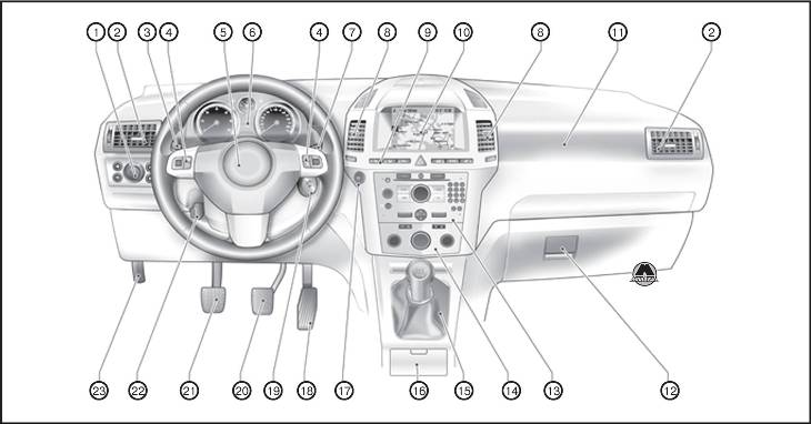
1. Выключатель осветительных приборов (Подсветка приборной панели; Задний противотуманный фонарь; Передние противотуманные фары; Регулировка угла наклона фар) 2. Боковые рефлекторы обдува 3. Сигналы поворота и смены ряда движения, мигание фар, ближний и дальний свет (Освещение нижней части дверного проёма; Стояночный свет; Круиз-контроль) 4. Органы управления на рулевом колесе 5. Звуковой сигнал/Подушка безопасности водителя 6. Приборы 7. Стеклоочистители, стеклоомыватели ветрового стекла, омыватели фар 8. Центральные рефлекторы обдува 9. Левое сидение с подогревом/ Система обнаружения спустившей шины/Система контроля давления воздуха в шинах/Ультразвуковая система помощи при парковке/Аварийная световая сигнализация/Центральный замок/Спортивный режим/Правое сидение с подогревом/Селектор выбора топлива 10. Информационный дисплей/Бортовой компьютер/Электронная система климат-контроля 11. Подушка безопасности переднего пассажира 12. Перчаточный ящик 13. Информационно-развлекательная система 14. Климат-контроль 15. Рычаг селектора, механическая коробка передач/Автоматизированная механическая коробка передач/Автоматическая коробка передач 16. Пепельница 17. Кнопка Start/Stop 18. Педаль акселератора 19. Замок зажигания с блокировкой рулевого колеса/Сенсорная панель для экстренного режима работы системы отпирания дверей и запуска двигaтeля/Open&Start 20. Педаль тормоза 21. Педаль сцепления 22. Регулировка положения рулевого колеса 23. Ручка отпирания капота
- Главная
- Opel
- Zafira
- Руководство по ремонту Opel Zafira 2005-2012 г.в.
Год выпуска:
2005 — 2012 гг.
Найдено 6 книг стоимостью от 512 руб.
Быстро купить книгу в оригинальной качественной версии PDF от издательства
Найдено 5 книг стоимостью от 1400 руб.
Купить бумажную версию книги с доставкой по вашему адресу
Скачать руководство с предоставленного файлообменника
Справочное иллюстрированное фотографиями руководство по ремонту Opel Zafira, инструкция по работе и пособие по техническому обслуживанию универсалов повышенной вместимости Opel Zafira с 2005 по 2012 годы выпуска. Автомобили снабжены бензиновыми двигателями внутреннего сгорания литражом 11,6 (Z16XEP, Z16XE1, Z16XER), 1,8 (Z18XER), 2,0 (Z18XER), 2,2 (Z22YH) и дизелями литражом 1,7 (A17DTJA, A17DTR), 1,9 (Z19DTL, Z19DT).
Книга должна помочь всем владельцам автомобилей Opel Zafira с кузовом мини-вэн правильно эксплуатировать автомобиль в любых условиях, не тратить лишние деньги на ремонт. Руководство снабжено правилами обслуживания техники. Но даже опытные рабочие СТО и мастера из многих автосервисов и мастерских смогут быстрее и четче делать качественный ремонт, обладая этой книгой.
Также в разделах издания показаны детальные, хорошо проиллюстрированные описания всех систем, узлов, компонентов и элементов автомобиля Opel Zafira. Все проводимые работы, связанные с эксплуатацией и устранением поломок машины описаны постепенно, шаг за шагом, что бы вы смогли легко во всем разобраться.
В специальные главы данного руководства входят инструкция по эксплуатации Opel Zafira и схематическое изображение электрооборудования автомобиля.
| Магазин | Тип книги | Цена | Информация |
|---|---|---|---|
| AUTODATA | Книга | 1400 руб. | |
| AUTOINFORM96 | Книга | 1877 руб. | |
| BOOK24 | Книга | 2378 руб. | |
| CHITAI-GOROD | Книга | 2378 руб. | |
| BOOKVOED | Книга | 2399 руб. |