-
Contents
-
Table of Contents
-
Bookmarks
Quick Links
RWF40…
Compact Universal Controller
optimized for temperature and pressure control through the control of modulating or multi-stage burners
User Manual
The RWF40… controller and this User Manual are intended for use by OEMs which integrate the controller into
their products!
Siemens Building Technologies
Landis & Staefa Division
CC1B7865E
February 10, 2000
Related Manuals for Siemens RWF40 Series
Summary of Contents for Siemens RWF40 Series
-
Page 1
User Manual The RWF40… controller and this User Manual are intended for use by OEMs which integrate the controller into their products! Siemens Building Technologies Landis & Staefa Division CC1B7865E February 10, 2000… -
Page 2
2/56 CC1B7865E February 10, 2000 Landis & Staefa Division… -
Page 3: Table Of Contents
Contents Introduction ………………6 General notes …………………….6 Description ……………………6 Typographical conventions……………….7 1.3.1 Warning symbols ………………….7 1.3.2 Notification symbols ………………….7 1.3.3 Presentation ……………………7 Type of unit ……………….8 Type field ……………………8 Installation ………………..9 Installation site and climatic conditions …………..9 Dimensions……………………9 Side-by-side mounting………………..10 Mounting in a panel cutout………………10 Cleaning the front panel ………………..11 Removing the controller module …………….11 Electrical connections ……………
-
Page 4
Operation ………………..29 Basic display…………………… 30 6.1.1 Meaning of the display and buttons…………….30 User level……………………31 6.2.1 Changing the setpoints………………..31 6.2.2 Manual operation of a modulating burner…………..33 6.2.3 Manual operation of a two-stage burner……………. 33 6.2.4 Start self-setting ………………….34 6.2.5 Display of the software version and unit of actual value ………. -
Page 5
Technical data ………………51 11.1 Inputs ……………………..51 11.1.1 Analog input 1 (actual value) ………………51 11.1.2 Analog input 2 (external setpoint, setpoint shift) …………51 11.1.3 Analog input 3 (outside temperature)…………….52 11.1.4 Binary input «D1»………………….52 11.1.5 Binary input «D2»………………….52 11.2 Outputs …………………….52 11.2.1 Output 1 (release of burner)……………….52 11.2.2… -
Page 6: Introduction
1. Introduction 1.1 General notes Please read this User Manual before starting up the controller. Keep the Manual in a place that is accessible to all users at all times. Please help us improve the Manual. Your suggestions will be welcome. All necessary settings and, where required, settings inside the unit are described in this User Manual, for controller software version 126.01.01.
-
Page 7: Typographical Conventions
1. Introduction 1.3 Typographical conventions 1.3.1 Warning symbols The signs for Danger and Caution are used in this Manual under the following conditions: Danger This symbol is used where there may be a danger to personnel if the instructions are disregarded or not strictly followed! Caution This symbol is used where there may be damage to equipment or data if the…
-
Page 8: Type Of Unit
2. Type of unit 2.1 Type field Location The type field is glued onto the housing. The type designation consists of operating voltage and type reference of the unit. Types Type of unit Description RWF40.000A97 Basic version with 3-position output RWF40.010A97 ¹·…
-
Page 9: Installation
3. Installation 3.1 Installation site and climatic conditions − The installation site should be as free as possible from vibrations, dust and corrosive media − The controller should be installed as far away as possible from sources of electromagnetic fields, such as frequency converters or high-voltage ignition transformers Relative humidity: <…
-
Page 10: Side-By-Side Mounting
3. Installation 3.3 Side-by-side If several controllers are mounted side-by-side or above one another in a control panel, the minimum spacing must be observed, namely 30.5 mm vertically and 10.5 mm horizontally. 3.4 Mounting in a panel cutout ✱ ✱ ✱ ✱ Place the seal provided onto the controller housing.
-
Page 11: Cleaning The Front Panel
3. Installation 3.5. Cleaning the front panel The front panel can be cleaned with normal washing and rinsing agents or detergents. It is not resistant to corrosive acids, caustic solutions and abrasive cleaners, or cleaning with high-pressure cleaners! 3.6 Removing the controller module The controller module can be removed from the housing for servicing.
-
Page 12: Electrical Connections
4. Electrical connections 4.1 Installation notes − The choice of cable, the installation and the electrical connections of the controller Safety regulations must conform to the regulations of VDE 0100 «Regulations for the installation of power circuits with nominal voltages below AC 1000 V», or appropriate local regulations −…
-
Page 13: Block Diagram
4. Electrical connections 4.2 Block diagram 3 analog inputs Release of burner Input 1: Output 1: Actual value — Relay (N.O. contact) for Pt100, Ni100, Pt1000, Ni1000 thermocouples or standard signals 3-position output Input 2: Output 2: External setpoint, -Relay (reg. unit opens) setpoint shift Ω…
-
Page 14: Assignment Of Terminals
4. Electrical connections 4.3 Assignment of terminals Electrical connections may only be made by qualified personnel! 7865z07/1199 Outputs Display LED Terminal no. Connection diagram Relay 1: release of burner Q14 pole Contact protection: Varistor S07K275 Q13 N.O. contact 7865a11/1199 ▲ Relay 2: regulating unit opens Y1 N.O.
-
Page 15
4. Electrical connections Analog input 1 (actual value) Terminals Connection diagram Thermocouple 7865a03/1099 Resistance thermometer in 3-wire circuit ϑ 7865a04/1099 Resistance thermometer in 2-wire circuit, line compensation through offset correction (OFF1) ϑ 7865a05/1099 Current input DC 0…20 mA, 4…20 mA 7865a06/1099 Voltage input DC 0…1 V, 0…10 V… -
Page 16
4. Electrical connections Binary inputs Terminals Connection diagram Operating mode selector Section 5.2 «High-fire operation» Setpoint shift / changeover Sections 5.4.1…5.4.4 7865a12/1099 Common ground Operating voltage, interface Terminals Connection diagram Operating voltage L1 line AC 100…240 V ±10 %, 48…63 Hz N neutral Technical earth 7865a18/1099… -
Page 17: Galvanic Separation
4. Electrical connections 4.4 Galvanic separation The diagram shows the maximum potential differences that may exist between the function modules in the controller. 3 analog inputs Limit comparator Input 1: Output 4: Actual value for Pt100, Ni100, — Relay (N.O. contact) Pt1000, Ni1000 thermocouples or standard signals…
-
Page 18: Operating Modes
5. Operating modes 5.1 Low-fire operation Low-fire operation means that only small amounts of heat are drawn from the boiler. A two- position controller maintains the setpoint, switching the burner on and off like a thermostat. This control mode is therefore also known as thermostat function. An adjustable Thermostat function switching differential ensures that the switching frequency of the burner can be selected to reduce wear.
-
Page 19: Modulating Burner, Modulating Output
5. Operating modes 5.2.2 Modulating burner, modulating output In diagram area (1), the thermostat function is active. In area (2), the controller is controlling to the adjusted setpoint. 7865w05/1099 HYS3 HYS1 100% The positioning signal is delivered as a standard signal via the modulating output. The modulating controller must be available and configured in the unit (optional).
-
Page 20: Two-Stage Burner, Modulating Output
5. Operating modes 5.2.4 Two-stage burner, modulating output In this case, a standard binary signal switches the second stage into circuit with analog output «X1» on reaching the switch-on threshold «HYS1» and switches it out of circuit at the lower switch-off threshold «HYS2». 7865w04/1099 HYS3 HYS2…
-
Page 21: Setpoint Changeover «Sp1 / Sp2», Analog Setpoint Shift
5. Operating modes 5.4.1 Setpoint changeover «SP1 / SP2», analog setpoint shift C111: XX1X … XX3X Outside sensor C111 and C112 are described in chapter 8 Heating curve slope H Setting: 0.0 … 4.0 Weather-dependent setpoint shift: C112: XX0X C112: XX1X SP1 via buttons SP1 via outside sensor C111: XXX2…
-
Page 22: Setpoint Changeover «Sp1» / External Setpoint
5. Operating modes 5.4.2 Setpoint changeover «SP1» / external setpoint C111: XX1X … XX3X Outside sensor C111 and C112 are described in chapter 8 Heating curve slope H Setting: 0.0 … 4.0 Weather-dependent setpoint shift: C112: XX0X C112: XX1X SP1 via buttons SP1 from outside sensor C111: X1XX …
-
Page 23: Setpoint «Sp1», Analog / Binary Setpoint Shift
5. Operating modes 5.4.3 Setpoint «SP1», analog / binary setpoint shift C111: XX1X … XX3X Outside sensor C111 and C112 are described in chapter 8 Heating curve slope H Setting: 0.0 … 4.0 Weather-dependent setpoint shift: C112: XX0X C112: XX1X SP1 via buttons SP1 via outside sensor C111: X6XX …
-
Page 24: External Setpoint, Binary Setpoint Shift
5. Operating modes 5.4.4 External setpoint, binary setpoint shift C111: X1XX … X5XX C111 and C112 are described in chapter 8 External setpoint C111: XXX1 C111: XXX2 C111: XXX0 Sections 5.4.1 and 5.4.2 Binary setpoint shift No function «Setpoint changeover …» D2 closed D2 open The values dSP and SP1 are entered at…
-
Page 25: Weather-Dependent Setpoint Shift
5. Operating modes 5.5 Weather-dependent setpoint shift The RWF40… can be configured in such a way that if a Landis & Staefa Ni1000 outside sensor (e.g. QAC22) is connected, a weather-dependent setpoint shift is implemented. The minimum and maximum setpoint values can be set by the lower setpoint limit «SPL»…
-
Page 26: Heating Curve Slope
5. Operating modes 5.5.1 Heating curve slope Slope «H» of the heating curve can be used to adjust the setpoint in response to the outside temperature, as shown in the diagram. The common origin of the heating curves is set at (20 °C / 20 °C). The effective range of the weather-adjusted setpoint is restricted by the setpoint limits «SPH»…
-
Page 27: Response Threshold «Q
5. Operating modes 5.6 Response threshold «Q» The response threshold «Q» defines how long and how low the actual value can drop before the system switches over to high-fire operation. An internal mathematical calculation using an integration function determines the sum of all the areas Q = Q1 + Q2 + Q3 , as shown in the diagram.
-
Page 28: Cold Start Of The Plant
5. Operating modes 5.7 Cold start of the plant When a heating system is switched off for a longer period of time, the actual value will fall. To achieve a faster control response, the controller starts immediately in high-fire operation as soon as the control deviation (x-w) has dropped below a certain limit value. This limit is calculated as follows: Limit value = 2 * (HYS1-HYS3) Example…
-
Page 29: Operation
6. Operation Assignment of levels All levels can be accessed from the basic display via the button, as shown in the diagram. The upper actual value display (red) indicates the actual value and the parameter values for the various levels. The setpoint and the parameters are indicated in the lower setpoint display (green).
-
Page 30: Basic Display
6. Operation 6.1 Basic display The diagram shows the RWF40… after switching on power. This condition is called the basic display. The actual value and the currently active setpoint are shown here. Manual operation, self-setting, the user, parameter and configuration levels can be activated from here.
-
Page 31: User Level
6. Operation Initialization All displays are lit up; the setpoint display flashes for about 10 seconds after switching on power. Manual operation The actual value is indicated on the upper display. The LED for manual operation is on. Depending on the operating mode and the type of controller, the setpoint or the level of the manual actuator position is shown on the setpoint display (green).
-
Page 32
6. Operation Basic display 60.3 65.0 User level 65.0 (Display depends on code 111) EXIT SP 1 10.0 70.0 Depending on the EXIT configuration of binary input 2: — dSP SP 2 -Sp2 Measurement of the 10.0 outside temperature EXIT via analog input 3 50.0 Measurement of the… -
Page 33: Manual Operation Of A Modulating Burner
6. Operation 6.2.2 Manual operation, modulating burner ✱ ✱ ✱ ✱ EXIT Press for 5 s The LED above the hand symbol lights up. ✱ ✱ ✱ ✱ Change the regulating unit’s position with ▲ and ▼ 3-position controller Relay 2 opens the regulating unit as long as ▲ is pressed. Relay 3 closes the regulating unit as long as ▼…
-
Page 34: Start Self-Setting
6. Operation 6.2.4 Start self-setting ✱ ✱ ✱ ✱ + ▼ Start self-setting with ✱ ✱ ✱ ✱ Cancel with ▲ 7865z10/1199 When «tunE» stops flashing, self-setting has stopped. ✱ ✱ ✱ ✱ Accept the parameters that have been determined by pressing ▲ (press the button for at least 2 s!) It is not possible to start «tunE»…
-
Page 35: Parameter Level
6. Operation 6.3 Parameter level The parameters involved in the adaptation of the controller to the controlled system are set here after the system has been started up. Within the level, you can proceed to the next parameter by pressing The display of the individual parameters depends on the type of controller.
-
Page 36: Parameter Settings
7. Parameter settings The parameter is shown on the lower setpoint display (green) and the value on the upper / actual value display (red). 7865p06/0200 Parameter Display Value range Factory Remarks setting Output 4 Limit value for limit -1999…+9999 digit comparator HYSt Measured value…
-
Page 37
7. Parameter settings The parameter is shown on the lower / setpoint display (green) and the value on the upper / actual value display (red). 7865p06/0200 Display Parameter Value range Factory Remarks setting Actuator running 10…3000 s 15 s Utilized running time of the valve for time 3-position controllers Switch-on threshold… -
Page 38: Configuration
8. Configuration 8.1 C111 inputs 0000 C111 7865p03/0200 Analog input 1 Pt100, 3-wire Pt100, 2-wire Ni100, 3-wire Ni100, 2-wire Pt1000, 3-wire, Landis & Staefa IEC 751 Pt1000, 2-wire, Landis & Staefa IEC 751 Ni1000, 3-wire, DIN 43760 Ni1000, 2-wire, DIN 43760 Ni1000, 3-wire, Landis &…
-
Page 39
8. Configuration 0000 C111 7865p03/0200 Analog input 3 No function Outside sensor Pt1000, 2-wire, Landis & Staefa IEC 751 Outside sensor Ni1000, 2-wire, DIN 43760 Outside sensor Ni1000, 2-wire, Landis & Staefa Function of binary input «D2» No function Setpoint changeover Setpoint shift (binary) Factory setting Landis &… -
Page 40: C112 Limit Comparator, Controller Type, Setpoint «Sp1», Locking
8. Configuration 8.2 C112 limit comparator, controller type, setpoint «SP1», locking 0000 C112 7865p04/0200 Limit comparator No function (lk off) lk1, input 1 lk2, input 1 lk3, input 1 lk4, input 1 lk5, input 1 lk6, input 1 lk7, input 1 lk8, input 1 lk7, input 2 lk8, input 2…
-
Page 41
8. Configuration Function Ik1 Window function: relay «K6» is active when the measured value lies within a window around the setpoint (w). Example: w = 80 °C, AL = 5, HYSt = 2 Measured value rising: relay «K6» switches on at 76 °C and off at 86 °C. Measured value falling: relay «K6»… -
Page 42
8. Configuration Function Ik4 As for lk3, but with inverted switching function. Output 4 HYSt Measured value 7865d03e/0300 HYSt = switching differential AL = interval from setpoint Chapter 7 «Parameter settings» Function Ik5 Upper limit signaling Function: relay inactive when measured value > (setpoint + limit value). Example: w = 80 °C, AL = 10, HYSt = 2 Measured value rising: relay «K6»… -
Page 43
8. Configuration Function Ik7 The switching point is independent of the controller setpoint; only the limit value «AL» determines the switching point. Function: relay is active when measured value > limit value. Example: AL = 50, HYSt = 2 Measured value rising: relay «K6» switches on at 51 °C. Measured value falling: relay «K6»… -
Page 44: C113 Unit Address, Dimensional Unit, Out-Of-Range
8. Configuration 8.3 C113 instrument address, dimensional unit, out-of-range The setting for the decimal place affects actual value-dependent parameters! 0000 C113 7865p05/0200 Unit address Address 0 Address 1 Address 99 Decimal places, dimensional unit No decimal place, °C One decimal place, °C No decimal place, °F One decimal place, °F Signal for out-of-range…
-
Page 45: Scl Scaling Of Standard Signal Range Start, Analog Input 1
8. Configuration 8.3.1 «SCL» scaling of standard signal range start, analog input 1 Example SCL = 20; SCH = 100 °C 0 mA (start) corresponds to a measured value of 20 °C 0 mA 20 mA 0 °C 20 °C 100 °C Value range: -1999…+9999 digit Factory setting: 0 digit…
-
Page 46: Sch2 Scaling Of Standard Signal Range End, Analog Input 2
8. Configuration 8.3.4 «SCH2» scaling of standard signal range end, analog input 2 Example SCH2 = 80: 20 mA corresponds to a measured value of 80 °C, as already described Value range: -1999…+9999 digit Factory setting: 100 digit 8.3.5 «SPL» lower setpoint limit The controller restricts the setpoints to the value that is set.
-
Page 47: Self-Setting Function
9. Self-setting function 9.1 Self-setting function in high-fire operation «tunE» is only possible in high-fire operation, in the «modulating burner» mode. The self-setting function «tunE» is a pure software function unit that is integrated into the controller. In the «modulating» mode of operation, «tunE» tests the response of the controlled system to steps of the positioning signal according to a special procedure.
-
Page 48
9. Self-setting function Start 7865d13/1099 The controlled system data which are recorded for the forced oscillations are used to calculate the controller parameters «rt, dt, Pb.1» and a filter time constant for actual value filtering that is optimized for this controlled system. −… -
Page 49: Checking The Controller Parameters
9. Self-setting function 9.2 Checking the controller parameters The optimum adjustment of the controller to the controlled system can be checked by recording a startup sequence with the control loop closed. The following diagrams indicate possible incorrect adjustments, and their correction. Example The response to a setpoint change is shown here for a 3 order controlled system for a…
-
Page 50: What To Do If
10. What to do, if … 10.1 …numbers are flashing on the display This is an indication that a measured value is not being acquired correctly. The detection of measured value range crossings depends on the type of sensor used. Section 11.3.2 «Measured value circuit monitoring»…
-
Page 51: Technical Data
11. Technical data 11.1 Inputs 11.1.1 Analog input 1 (actual value) For resistance thermometers, thermocouples or standard signals with 2 order digital filter (configurable). Resistance thermometers In 2-wire or 3-wire circuit: Type Measured value range Pt100, Pt1000 -200…+850 °C Ni100, Ni1000 DIN 43760 -60…+250 °C Ni1000 from Landis &…
-
Page 52: Analog Input 3 (Outside Temperature)
11. Technical data 11.1.3 Analog input 3 (outside temperature) For resistance thermometers in a 2-wire circuit, with fixed filter time constants (21 h 18 min for the weather-dependent setpoint enable) Resistance thermometer Type Measured value range Pt1000 -200…+850 °C Ni1000 DIN 43760 -60…+250 °C Ni1000 from Landis &…
-
Page 53: Output 5, Modulating Output (Option)
11. Technical data 11.2.4 Output 5, modulating output (option) Continuous output, electrically isolated from the analog inputs: ∆U < AC 30 V , ∆U < DC 50 V Standard signals Load, burden Load = > 500 Ω DC 0…10 V (short-circuit-proof) Burden = <…
-
Page 54: Measured Value Accuracy
11. Technical data 11.3.1 Measured value accuracy Resolution: > 15 bit Measured value accuracy Ambient temperature error Resistance thermometer: ≤ 0.05 % ≤ 50 ppm / K Thermocouples: ≤ 0.25 % ≤ 100 ppm / K Standard signals: ≤ 0.1 % ≤…
-
Page 55: Current Settings
12. Actual settings 12.1 Process data Parameter Display Value range Factory Setting setting Setpoint 1 SPL-SPH Setpoint 2 (option) SPL-SPH Digital setpoint shift (optional) SPL-SPH Outside temperature (optional) Section 8.1 «C111 Inputs» Pre-definition of external setpoint SPL-SPH SP.E These parameters are affected by the setting for the decimal place. 12.2 Parameter level Parameter Display…
-
Page 56: Configuration Level
Landis & Staefa Division Berliner Ring 23 D — 76347 Rastatt Tel. 0049 — 7222 — 598 — 0 Fax. 0049 — 7222 — 53182 2000 Siemens Building Technologies AG http://www.landisstaefa.com 56/56 CC1B7865E February 10, 2000 Landis & Staefa Division…
18/06/18
Golden Panda Award.
The China-Italy Chamber of Commerce (CICC) is glad to inform you that the 9th edition of the Italian Grand Gala Panda d’Oro Award was successfully held on June 9th, 2018 at The Ritz-Carlton Shanghai, Pudong.
With the patronage of the Ministry of Economic Development (MiSE) and the Italian Embassy in the P.R.C., the Panda d’Oro represents a signature event for the Sino-Italian business community to strengthen existing relations and build new ones.
details
![]()
RWF40…
Compact Universal Controller
optimized for temperature and pressure control through the control of modulating or multi-stage burners
User Manual
The RWF40… controller and this User Manual are intended for use by OEMs which integrate the controller into their products!
CC1B7865E
February 10, 2000
Siemens Building Technologies
Landis & Staefa Division

|
Contents |
||
|
1. |
Introduction ……………………………………………………………………………… |
6 |
|
1.1 |
General notes ………………………………………………………………………………………………….. |
6 |
|
1.2 |
Description ……………………………………………………………………………………………………… |
6 |
|
1.3 |
Typographical conventions………………………………………………………………………………. |
7 |
|
1.3.1 |
Warning symbols ………………………………………………………………………………………………. |
7 |
|
1.3.2 |
Notification symbols …………………………………………………………………………………………… |
7 |
|
1.3.3 |
Presentation……………………………………………………………………………………………………… |
7 |
|
2. |
Type of unit………………………………………………………………………………. |
8 |
|
2.1 |
Type field ………………………………………………………………………………………………………… |
8 |
|
3. |
Installation ……………………………………………………………………………….. |
9 |
|
3.1 |
Installation site and climatic conditions ……………………………………………………………. |
9 |
|
3.2 |
Dimensions……………………………………………………………………………………………………… |
9 |
|
3.3 |
Side-by-side mounting……………………………………………………………………………………. |
10 |
|
3.4 |
Mounting in a panel cutout……………………………………………………………………………… |
10 |
|
3.5 |
Cleaning the front panel …………………………………………………………………………………. |
11 |
|
3.6 |
Removing the controller module …………………………………………………………………….. |
11 |
|
4. |
Electrical connections …………………………………………………………….. |
12 |
|
4.1 |
Installation notes……………………………………………………………………………………………. |
12 |
|
4.2 |
Block diagram ……………………………………………………………………………………………….. |
13 |
|
4.3 |
Assignment of terminals ………………………………………………………………………………… |
14 |
|
4.4 |
Galvanic separation ……………………………………………………………………………………….. |
17 |
|
5. |
Operating modes…………………………………………………………………….. |
18 |
|
5.1 |
Low-fire operation………………………………………………………………………………………….. |
18 |
|
5.2 |
High-fire operation …………………………………………………………………………………………. |
18 |
|
5.2.1 |
Modulating burner, 3-position output…………………………………………………………………… |
18 |
|
5.2.2 |
Modulating burner, modulating output…………………………………………………………………. |
19 |
|
5.2.3 |
Two-stage burner, 3-position output …………………………………………………………………… |
19 |
|
5.2.4 |
Two-stage burner, modulating output …………………………………………………………………. |
20 |
|
5.3 |
Safety shutdown ……………………………………………………………………………………………. |
20 |
|
5.4 |
Pre-defined setpoint ………………………………………………………………………………………. |
20 |
|
5.4.1 |
Setpoint changeover «SP1 / SP2», analog setpoint shift ………………………………………. |
21 |
|
5.4.2 |
Setpoint changeover «SP1» / external setpoint……………………………………………………. |
22 |
|
5.4.3 |
Setpoint «SP1», analog / binary setpoint shift ……………………………………………………… |
23 |
|
5.4.4 |
External setpoint, binary setpoint shift ………………………………………………………………… |
24 |
|
5.5 |
Weather-dependent setpoint shift …………………………………………………………………… |
25 |
|
5.5.1 |
Heating curve slope …………………………………………………………………………………………. |
26 |
|
5.6 |
Response threshold «Q»………………………………………………………………………………… |
27 |
|
5.7 |
Cold start of the plant …………………………………………………………………………………….. |
28 |
|
Landis & Staefa Division |
CC1B7865E |
February 10, 2000 |
3/56 |

|
6. |
Operation ……………………………………………………………………………….. |
29 |
|
|
6.1 |
Basic display…………………………………………………………………………………………………. |
30 |
|
|
6.1.1 |
Meaning of the display and buttons……………………………………………………………………. |
30 |
|
|
6.2 |
User level………………………………………………………………………………………………………. |
31 |
|
|
6.2.1 |
Changing the setpoints…………………………………………………………………………………….. |
31 |
|
|
6.2.2 |
Manual operation of a modulating burner……………………………………………………………. |
33 |
|
|
6.2.3 |
Manual operation of a two-stage burner……………………………………………………………… |
33 |
|
|
6.2.4 |
Start self-setting ……………………………………………………………………………………………… |
34 |
|
|
6.2.5 |
Display of the software version and unit of actual value ……………………………………….. |
34 |
|
|
6.3 |
Parameter level ……………………………………………………………………………………………… |
35 |
|
|
6.3.1 |
Enter parameters…………………………………………………………………………………………….. |
35 |
|
|
6.4 |
Configuration level ………………………………………………………………………………………… |
35 |
|
|
6.4.1 |
Changing the configuration code……………………………………………………………………….. |
35 |
|
|
7. |
Parameter settings ………………………………………………………………….. |
36 |
|
|
8. |
Configuration………………………………………………………………………….. |
38 |
|
|
8.1 |
C111 |
inputs……………………………………………………………………………………………… |
38 |
|
8.2 |
C112 |
limit comparator, controller type, setpoint «SP1», locking ………………… |
40 |
|
8.3 |
C113 |
unit address, dimensional unit, out-of-range…………………………………….. |
44 |
|
8.3.1 |
SCL |
scaling of standard signal range start, analog input 1…………………………….. |
45 |
|
8.3.2 |
SCH |
scaling of standard signal range end, analog input 1……………………………… |
45 |
|
8.3.3 |
SCL2 |
scaling of standard signal range start, analog input 2…………………………….. |
45 |
|
8.3.4 |
SCH2 |
scaling of standard signal range end, analog input 2……………………………… |
46 |
|
8.3.5 |
SPL |
lower setpoint limit…………………………………………………………………………….. |
46 |
|
8.3.6 |
SPH |
upper setpoint limit ……………………………………………………………………………. |
46 |
|
8.3.7 |
OFF1 |
actual value correction for analog input 1 …………………………………………….. |
46 |
|
8.3.8 |
OFF2 |
actual value correction for analog input 2 …………………………………………….. |
46 |
|
8.3.9 |
OFF3 |
actual value correction for analog input 3 …………………………………………….. |
46 |
|
8.3.10 |
dF1 |
2nd order digital filter for analog input 1 ………………………………………………… |
46 |
|
9. |
Self-setting function………………………………………………………………… |
47 |
|
|
9.1 |
Self-setting function in high-fire operation ……………………………………………………… |
47 |
|
|
9.2 |
Checking the controller parameters ……………………………………………………………….. |
49 |
|
|
10. |
What to do if……………………………………………………………………………. |
50 |
|
|
10.1 |
…numbers are flashing on the display ……………………………………………………………. |
50 |
|
4/56 |
CC1B7865E |
February 10, 2000 |
Landis & Staefa Division |

|
11. |
Technical data ………………………………………………………………………… |
51 |
|
11.1 |
Inputs ……………………………………………………………………………………………………………. |
51 |
|
11.1.1 |
Analog input 1 (actual value) …………………………………………………………………………….. |
51 |
|
11.1.2 |
Analog input 2 (external setpoint, setpoint shift)…………………………………………………… |
51 |
|
11.1.3 |
Analog input 3 (outside temperature)………………………………………………………………….. |
52 |
|
11.1.4 |
Binary input «D1»…………………………………………………………………………………………….. |
52 |
|
11.1.5 |
Binary input «D2»…………………………………………………………………………………………….. |
52 |
|
11.2 |
Outputs …………………………………………………………………………………………………………. |
52 |
|
11.2.1 |
Output 1 (release of burner)………………………………………………………………………………. |
52 |
|
11.2.2 |
Output 2, 3 (3-position output) …………………………………………………………………………… |
52 |
|
11.2.3 |
Output 4 (limit comparator) ……………………………………………………………………………….. |
52 |
|
11.2.4 |
Output 5, modulating output (option)…………………………………………………………………… |
53 |
|
11.2.5 |
Transducer supply……………………………………………………………………………………………. |
53 |
|
11.2.6 |
Interface RS-485 (optional)……………………………………………………………………………….. |
53 |
|
11.3 |
General ratings………………………………………………………………………………………………. |
53 |
|
11.3.1 |
Measured value accuracy …………………………………………………………………………………. |
54 |
|
11.3.2 |
Measured value circuit monitoring ……………………………………………………………………… |
54 |
|
11.3.3 |
Environmental conditions………………………………………………………………………………….. |
54 |
|
12. |
Current settings………………………………………………………………………. |
55 |
|
12.1 |
Process data………………………………………………………………………………………………….. |
55 |
|
12.2 |
Parameter level………………………………………………………………………………………………. |
55 |
|
12.3 |
Configuration level…………………………………………………………………………………………. |
56 |
|
Landis & Staefa Division |
CC1B7865E |
February 10, 2000 |
5/56 |

1. Introduction
1.1 General notes
)Please read this User Manual before starting up the controller. Keep the Manual in a place that is accessible to all users at all times. Please help us improve the Manual.
Your suggestions will be welcome.
*All necessary settings and, where required, settings inside the unit are described in this User Manual, for controller software version 126.01.01.
Ö Section 6.2.5 «Display software version and dimensional unit»
|
Should any difficulties arise during commissioning, you are asked not to carry out any |
||||||||||||||||||||
|
unauthorized manipulations on the unit. You could endanger your rights under the unit |
||||||||||||||||||||
|
warranty! Please contact us in such a case. |
||||||||||||||||||||
|
When returning modules, assemblies or components to Landis & Staefa, the regulations |
||||||||||||||||||||
|
of DIN EN 100 015 «Protection of electrostatically sensitive devices» must be observed. |
||||||||||||||||||||
|
Use only the appropriate ESD packaging for transport. |
||||||||||||||||||||
|
Please note that we cannot accept any liability for damage caused by ESD. |
||||||||||||||||||||
|
ESD = electrostatic discharge |
||||||||||||||||||||
|
1.2 Description |
||||||||||||||||||||
|
Use |
The RWF40… is used primarily for controlling temperature or pressure in oilor gas-fired |
|||||||||||||||||||
|
heating plants. It is a compact 3-position controller without position feedback that acts |
||||||||||||||||||||
|
on the burner. An external switch can be used to change it over to a 2-position controller |
||||||||||||||||||||
|
for the control of two-stage burners. The built-in thermostat function switches the burner |
||||||||||||||||||||
|
on and off. An adjustable response threshold is used to switch to a higher burner output |
||||||||||||||||||||
|
(high-fire operation). |
||||||||||||||||||||
|
Control |
A shift controller controls the temperature or pressure. Minimum and maximum limits for |
|||||||||||||||||||
|
the setpoint can be set. A self-setting function is available as a standard feature. |
||||||||||||||||||||
|
The plug-in controller module measures 96 x 48 x 127.5 mm and is especially suited for |
||||||||||||||||||||
|
mounting in control panels. The controller incorporates two 4-digit 7-segment displays |
||||||||||||||||||||
|
for the actual value (red) and setpoint (green). A limit comparator is also provided and |
||||||||||||||||||||
|
its switching behavior can be set on the configuration level. |
||||||||||||||||||||
|
A selection can be made between eight different limit comparator functions. |
||||||||||||||||||||
|
Options |
An RS-485 interface is used for integration into a data network. Output 5 can be used as |
|||||||||||||||||||
|
a modulating output for modulating or 2-stage operation. |
||||||||||||||||||||
|
All connections are made via screw terminals at the rear of the unit. |
|
6/56 |
CC1B7865E |
February 10, 2000 |
Landis & Staefa Division |

1. Introduction
1.3 Typographical conventions
1.3.1 Warning symbols The signs for Danger and Caution are used in this Manual under the following conditions:
Danger This symbol is used where there may be a danger to personnel if the instructions are disregarded or not strictly followed!
*Caution This symbol is used where there may be damage to equipment or data if theinstructions are disregarded or not strictly followed!
Caution This symbol is used if pre-cautions must be taken in handling electrostatically sensitive components.
|
1.3.2 Notification symbols |
||
|
) |
Note |
This symbol is used to draw your special attention to a remark. |
ÖReference This symbol refers to additional information in other Manuals, chapters or sections.
|
abc¹. |
Footnote |
Footnotes are comments, referring to specific parts of the text. They consist of two |
|||||
|
parts: |
|||||||
|
1) The markings in the text are arranged as continuous superscript numbers |
|||||||
|
2) The footnote text is placed at the bottom of the page and starts with a number |
|||||||
|
and a period |
|||||||
|
Action |
This symbol indicates that a required action is described. |
||||||
|
The individual steps are indicated by an asterisk, e.g.: |
|||||||
|
Press the ▲ button |
|||||||
|
1.3.3 Presentation |
|||||||
|
Buttons |
Buttons are shown in a box. Either symbols or text are possible. If a button has multiple |
||||||
|
PGM |
|||||||
|
assignments, the text shown is always the one that corresponds to the function |
|||||||
|
currently used. |
|||||||
|
Button |
The representation of buttons combined with a plus sign means that first the |
||||||
|
EXIT |
|||||||
|
+ ▲ |
combi- |
EXIT |
button must be pressed and held down and then the other button. |
||||
nations
|
Landis & Staefa Division |
CC1B7865E |
February 10, 2000 |
7/56 |

2. Type of unit
2.1 Type field
Location
Types
Factory setting
Accessories
The type field is glued onto the housing. The type designation consists of operating voltage and type reference of the unit.
|
Type of unit |
Description |
|
RWF40.000A97 |
Basic version with 3-position output |
|
RWF40.010A97 ¹· |
|
|
RWF40.001A97 |
With additional modulating output |
|
RWF40.011A97 ¹· |
|
|
RWF40.002A97 |
With additional modulating output and |
|
RWF40.012A97 ¹· |
RS-485 interface |
|
¹· Packing variants |
*The supply voltage connected must match the voltage given on the type field.
The measured value range and the analog inputs are set at the factory.
ÖChapter 8 «Configuration»
Adapter frame ARG40 for plants where the pre-decessor model RWF32… was used, which shall be converted to the RWF40… .
Bracket ARG41 for mounting the RWF40… on 35 mm DIN rails conforming to DIN 46277.
Dummy cover AVA10.200/109 for covering a control panel cutout for the RWF40…
|
8/56 |
CC1B7865E |
February 10, 2000 |
Landis & Staefa Division |

3. Installation
3.1Installation site and climatic conditions
−The installation site should be as free as possible from vibrations, dust and corrosive media
−The controller should be installed as far away as possible from sources of electromagnetic fields, such as frequency converters or high-voltage ignition transformers
Relative humidity: < 95 % (non-condensing)
Ambient temperature range: -20…+50 °C
Storage temperature range: -40…+70 °C
3.2 Dimensions
48
112
43,5
Panel cutout to DIN 43700
|
45 +0,6 |
|
|
127,5 |
92 +0,8 |
|
15,5 |
7865m01e/0200 |
|
Landis & Staefa Division |
CC1B7865E |
February 10, 2000 |
9/56 |
3. Installation
3.3 Side-by-side
If several controllers are mounted side-by-side or above one another in a control panel, the minimum spacing must be observed, namely 30.5 mm vertically and 10.5 mm horizontally.
3.4Mounting in a panel cutout
Place the seal provided onto the controller housing.
*The unit must be installed with the seal so that no water or oil can penetrate the housing!
Insert the controller from the front into the panel cutout.
7865z08/0200
At the rear of the panel, push the fixing elements into the guide slots from the side or top. The flat faces of the fixing elements must lie against the housing.
Place the fixing elements against the rear of the panel, and tighten them evenly with a screwdriver.
|
10/56 |
CC1B7865E |
February 10, 2000 |
Landis & Staefa Division |
![]()
3. Installation
3.5. Cleaning the front panel
The front panel can be cleaned with normal washing and rinsing agents or detergents.
*It is not resistant to corrosive acids, caustic solutions and abrasive cleaners, or cleaning with high-pressure cleaners!
3.6Removing the controller module
The controller module can be removed from the housing for servicing.
The rules of DIN EN 100 015 «Protection of electrostatically sensitive devices » must be adhered to for internal work on the controller! No liability will be accepted for damage caused by electrostatic discharge.
7865z09/0200
Press the ribbed surfaces together (at top and bottom) and pull out the controller module.
|
Landis & Staefa Division |
CC1B7865E |
February 10, 2000 |
11/56 |

4. Electrical connections
4.1 Installation notes
Safety regulations
Fusing
Interference suppression
−The choice of cable, the installation and the electrical connections of the controller must conform to the regulations of VDE 0100 «Regulations for the installation of power circuits with nominal voltages below AC 1000 V», or appropriate local regulations
−The electrical connections may only be carried out by qualified personnel
−If contact with live parts is possible while working on the unit, the controller must be disconnected from the power supply at both poles
−An internal current-limiting resistor interrupts the supply voltage in the event of a shortcircuit. The external fusing should not be rated above 1 A (slow). The output relays must be fused for a maximum of 2 A to prevent contact welding in the event of a shortcircuit in the load circuit
ÖSection 11.2 «Outputs»
−No other loads may be connected to the supply terminals of the controller
−The electromagnetic compatibility and interference suppression levels conform to standards and regulations listed under «Technical data»
ÖChapter 11 «Technical data»
− Input, output and supply cables should be routed separately, not parallel to one another
− Arrange sensor and interface cables as twisted and screened cables, and do not run them close to power cables or components. Ground the screening to the controller at one end to the «TE» terminal
|
− Earth the «TE» terminal of the controller to the protective earth. This cable must have |
|
|
a cross-sectional area that is at least as large as that of the supply cables. Earthing |
|
|
cables must be wired in a star configuration to a common earthing point connected to |
|
|
the protective earth of the supply. Earthing cables may not be looped from one |
|
|
controller to another |
|
|
Incorrect use |
− The unit is not suitable for installation in areas with an explosion hazard |
|
− Incorrect settings on the controller (setpoint, data of parameter and configuration |
|
|
levels) can affect the proper functioning of the following process or lead to damage. |
|
|
Safety devices that are independent of the controller, such as overpressure relief |
|
|
valves or temperature limiters / monitors should therefore always be provided, and |
|
|
only be capable of adjustment by qualified personnel. Please observe the appropriate |
|
|
safety regulations. Since self-setting cannot be expected to handle all possible control |
|
|
loops, the stability of the actual value that is produced should be checked |
|
|
− The analog inputs of the controller may not exceed a maximum voltage of AC 30 V or |
|
|
DC 50 V against «TE» |
|
|
Ö Section 4.3 «Galvanic separation» |
|
12/56 |
CC1B7865E |
February 10, 2000 |
Landis & Staefa Division |
4.2 Block diagram
3 analog inputs
Input 1:
Actual value
for Pt100, Ni100, Pt1000, Ni1000 thermocouples or standard signals
Input 2:
External setpoint, setpoint shift
for resistance 0 — 1 kΩ , or linearised
standard signals
Input 3:
Outside temperature for Pt1000, Ni1000
2 binary inputs
For potential-free contacts
Input 1:
Operating mode changeover
Input 2:
Setpoint shift / changeover
Operating voltage
AC 100 …240 V,
±10 %, 48…63 Hz
7865f01e/0200
4. Electrical connections
Release of burner
Output 1:
— Relay (N.O. contact)
3-position output
Output 2:
-Relay (reg. unit opens)
Output 3:
— Relay (reg. unit closes)
…RWF40 Limit comparator
Output 4:
— Relay (N.O. contact)
Transducer supply
DC 24 V, 30 mA (short-circuit-proof)
Modulating output (optional)
Output 5:
Modulating output,
DC 0…10 V, DC 0…20 mA,
DC 4…20 mA
Serial interface (optional)
RS-485
MOD bus protocol
Baud rate 9600
|
Landis & Staefa Division |
CC1B7865E |
February 10, 2000 |
13/56 |

4. Electrical connections
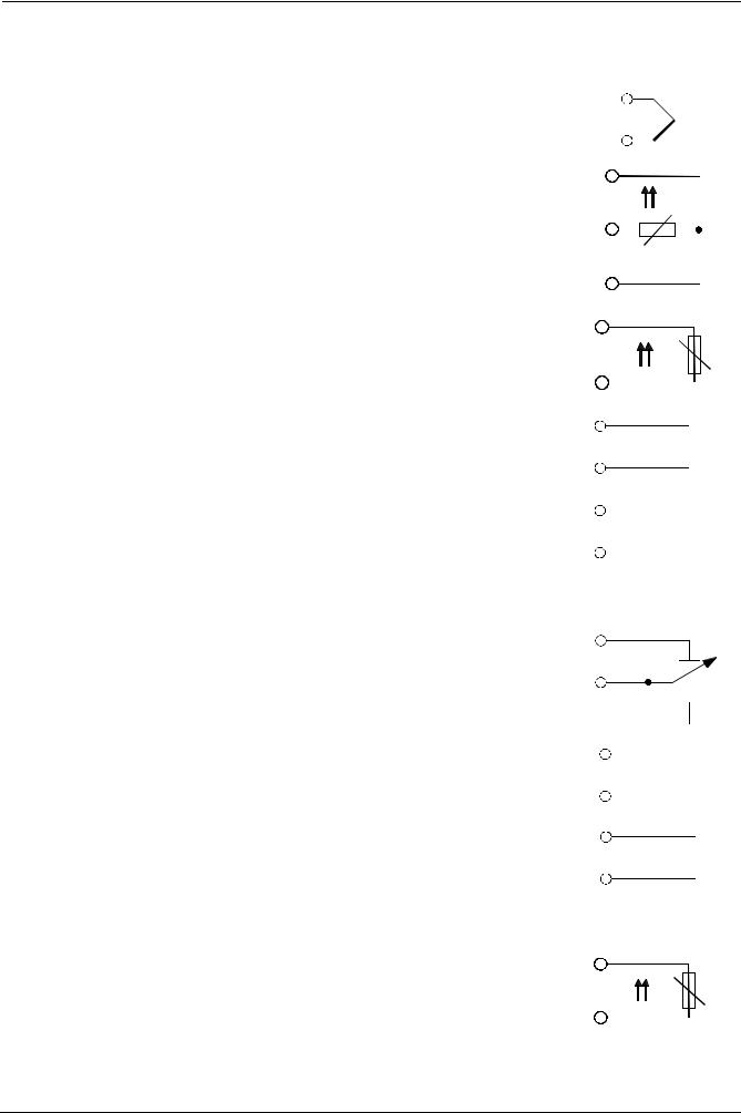
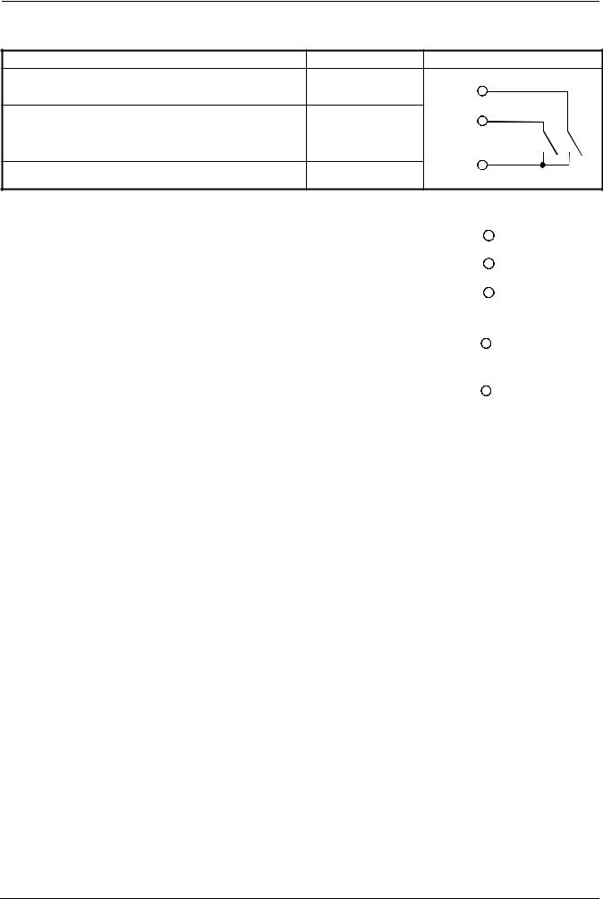
4.3 Assignment of terminals
Electrical connections may only be made by qualified personnel!
|
X1+ |
CB |
|
X1- |
CG |
|
G- |
CA |
|
G+ |
TE |
|
GND |
|
|
D1 |
L1 |
|
D2 |
N |
|
I1 |
Y2 |
|
M1 |
Q |
|
U1 |
Y1 |
|
G1+ |
Q13 |
|
XB6 |
Q14 |
|
M6 |
|
|
XU6 |
|
|
B9 |
Q63 |
|
M9 |
Q64 |
7865z07/1199
|
Outputs |
Display LED |
Terminal no. |
Connection diagram |
|||||||||||
|
Relay 1: release of burner |
Q14 pole |
Q14 |
||||||||||||
|
Contact protection: |
P |
|||||||||||||
|
Varistor S07K275 |
S |
|||||||||||||
|
Q13 N.O. contact |
Q13 |
|||||||||||||
|
7865a11/1199 |
||||||||||||||
|
Relay 2: regulating unit opens |
▲ |
Y1 N.O. contact |
Y1 |
S |
||||||||||
|
Contact protection: |
||||||||||||||
|
RC unit |
||||||||||||||
|
P |
||||||||||||||
|
Q common pole |
Q |
|||||||||||||
|
Relay 3: regulating unit closes |
▼ |
|||||||||||||
|
Contact protection: |
P |
|||||||||||||
|
RC unit |
||||||||||||||
|
Y2 N.O. contact |
S |
|||||||||||||
|
Y2 |
||||||||||||||
|
7865a16/1099 |
||||||||||||||
|
Relay 4: limit comparator |
K6 |
Q64 pole |
Q64 |
|||||||||||
|
Contact protection: |
P |
|||||||||||||
|
Varistor S07K275 |
||||||||||||||
|
S |
||||||||||||||
|
Q63 N.O. contact |
Q63 |
|||||||||||||
|
7865a15/1099 |
||||||||||||||
|
Modulating output (optional) |
X1+ |
X1+ |
+ |
|||||||||||
|
DC 0 (4)…20 mA, 0 (2)…10 V |
||||||||||||||
|
X1- |
X1- |
— |
||||||||||||
|
7865a17/1099 |
||||||||||||||
|
14/56 |
CC1B7865E |
February 10, 2000 |
Landis & Staefa Division |
4. Electrical connections
|
Analog input 1 (actual value) |
Terminals |
Connection diagram |
|||||||||||
|
Thermocouple |
I1 |
I1 |
+ |
||||||||||
|
M1 |
M17865a03/1099 |
— |
|||||||||||
|
Resistance thermometer in 3-wire circuit |
M1 |
M1 |
|||||||||||
|
ϑ |
|||||||||||||
|
G1+ |
G1+ |
||||||||||||
|
I1 |
I1 |
||||||||||||
|
7865a04/1099 |
|||||||||||||
|
Resistance thermometer in 2-wire circuit, line |
M1 |
M1 |
|||||||||||
|
compensation through offset correction (OFF1) |
ϑ |
||||||||||||
|
G1+ |
G1+ |
||||||||||||
|
7865a05/1099 |
|||||||||||||
|
Current input |
I1 |
I1 |
+ |
||||||||||
|
DC 0…20 mA, 4…20 mA |
|||||||||||||
|
M1 |
M1 |
— |
|||||||||||
|
7865a06/1099 |
|||||||||||||
|
Voltage input |
U1 |
U1 |
+ |
||||||||||
|
DC 0…1 V, 0…10 V |
|||||||||||||
|
M1 |
M1 |
— |
|||||||||||
|
7865a07/1099 |
|||||||||||||
|
Analog input 2 (setpoint and setpoint shift) |
Terminals |
Connection diagram |
|||||||||||
|
Resistance potentiometer |
XB6 start |
XB6 |
A |
||||||||||
|
Offset correction (OFF2) |
|||||||||||||
|
S |
|||||||||||||
|
M6 slider |
M6 |
||||||||||||
|
M6 end |
E |
||||||||||||
|
7865a08/1099 |
|||||||||||||
|
Current input |
XB6 |
XB6 |
+ |
||||||||||
|
DC 0..20 mA, 4…20 mA |
|||||||||||||
|
M6 |
M6 |
— |
|||||||||||
|
7865a09/1099 |
|||||||||||||
|
Voltage input |
XU6 |
XU6 |
+ |
||||||||||
|
DC 0…1 V, 0…10 V |
|||||||||||||
|
M6 |
M6 |
— |
|||||||||||
|
7865a10/1099 |
|||||||||||||
|
Analog input 3 (outside temperature) |
Terminals |
Connection diagram |
|||||||||||
|
Resistance thermometer in 2-wire circuit, line |
B9 |
B9 |
|||||||||||
|
compensation through offset correction (OFF3) |
ϑ |
||||||||||||
|
M9 |
M9 |
||||||||||||
|
7865a13/1099 |
|||||||||||||
|
Landis & Staefa Division |
CC1B7865E |
February 10, 2000 |
15/56 |
4. Electrical connections
|
Binary inputs |
Terminals |
Connection diagram |
|
Operating mode selector |
D1 |
D1 |
|
Ö Section 5.2 «High-fire operation» |
||
|
Setpoint shift / changeover |
D2 |
D2 |
|
Ö Sections 5.4.1…5.4.4 |
||
|
GND |
GND |
|
|
Common ground |
7865a12/1099 |
|
Operating voltage, interface |
Terminals |
Connection diagram |
||||
|
Operating voltage |
L1 line |
L1 |
||||
|
AC 100…240 V ±10 %, 48…63 Hz |
N |
|||||
|
N neutral |
||||||
|
TE |
||||||
|
Technical earth |
TE |
|||||
|
7865a18/1099 |
||||||
|
Operating voltage for transducer |
G+ |
G+ |
+ |
|||
|
DC 24 V / 30 mA |
||||||
|
G- |
G- |
— |
||||
|
7865a14/1099 |
||||||
|
Serial interface |
CA |
RxD / TxD+ |
||||
|
RS-485 |
CB |
RxD / TxD- |
||||
|
CG |
GND |
|
16/56 |
CC1B7865E |
February 10, 2000 |
Landis & Staefa Division |
4. Electrical connections
4.4 Galvanic separation
The diagram shows the maximum potential differences that may exist between the function modules in the controller.
3 analog inputs
Input 1:
Actual value for Pt100, Ni100, Pt1000, Ni1000
thermocouples or standard signals
Input 2:
External setpoint, setpoint shift
for resistance 0…1 k Ω , or standard signals
Input 3:
Outside temperature for Pt1000, Ni1000
2 binary inputs
for potential-free contacts
D1: operating mode changeover
D2: setpoint shift / changeover
Transducer supply
DC 24 V , 30 mA (short-circuit proof)
Modulating output (optional)
Output 5: Modulating output, DC 0…10 V,
DC 0…20 mA, 4…20 mA
Serial interface
RS-485 (optional)
MOD bus protocol baud rate 9600
Limit comparator
Output 4:
— Relay (N.O. contact)
Release of burner L1, N:
Output 1:
— Relay (N.O. contact)
3-position output L1, N:
Output 2:
— Relay (reg. unit opens)
Output 3:
— Relay (reg. unit closes)
Operating voltage L1, N:
AC 100…240 V ±10 %,
48…63 Hz
Max. insulation voltages:
DC 50 V
AC 400 V
AC 4000 V
Technical earth TE
7865f07e/1299
|
Landis & Staefa Division |
CC1B7865E |
February 10, 2000 |
17/56 |
Транскрипция содержимого страницы
Если ваш браузер не отображает страницу правильно, пожалуйста, читайте содержимое страницы ниже
РУКОВОДСТВО ПО
- ЭКСПЛУАТАЦИИ
- КАЛИБРОВКЕ
МОДУЛЯТОРА

SIEMENS RWF 40….

                 M12905NE Rev. 04 01/07
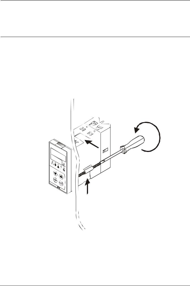
МОНТАЖ ПРИБОРА
Монтируйте прибор, используя специальные опоры, как показано на рисунке.
По электрическим подключениям прибора и датчиков выполните указания, приведенные на электрических
схемах горелки.
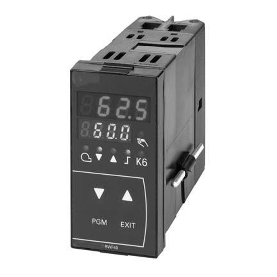
ПЕРЕДНЯЯ ПАНЕЛЬ ПРИБОРА
Фактическое значение или
значение параметра
(красное)
Задание или
наименование
параметра (зеленое) Работа в ручном
режиме
Разрешение
запуска горелки
Сигнал горелки Вспомогательный
увеличивается выход
Сигнал горелки Двухступенчатая
уменьшается работа
Уменьшить значение величить значение
(стрелка вниз) (стрелка вверх)
Клавиша
Клавиша выхода из
программирования
заданий
2
КАЛИБРОВКА ПРИБОРА
Прибор выходит с завода уже с некоторыми заданиями, действительными для 90% случаев, тем не менее, для задания
или изменения параметров выполните следующие операции:

1. Задание или изменения значения уставки:
При выключенной горелке (контакты последовательности термостаты/реле давления разомкнуты, т. е. клеммы 3-4
разомкнуты) нажимайте клавишу PGM менее 2 секунд, на дисплее внизу (зеленом) появляется SP1, стрелками вверх и
вниз задайте значение уставки на дисплее вверху (красном).
Для подтверждения значения нажмите клавишу PGM, затем - EXIT для выхода и возврата к нормальной работе.

2. Контроль или изменение параметров PID прибора (прилагаемая таблица 1):
Нажимайте клавишу PGM в течение более 2 секунд, на зеленом дисплее появляется обозначение AL, а на красном
дисплее - 0.
Стрелками вверх и вниз можно изменить значение на красном дисплее.
Для подтверждения нажмите PGM, при этом зеленый дисплей переходит к следующему параметру.
Повторите описанные выше операции для других параметров.
Для прерывания нажмите клавишу EXIT.
Перечень параметров PID см. в прилагаемой таблице (1).

3. Задания типа датчика для подключения к прибору (прилагаемая таблица 2):
При работающем в нормальном режиме приборе нажимайте клавишу PGM в течение 2 секунд, прибор переключается
на конфигурацию параметров PID, снова нажимайте клавишу PGM в течение еще 2 секунд.
На зеленом дисплее появляется обозначение C111, а на красном дисплее - код 9030.
Каждая цифра кода соответствует задаваемому параметру.
При нажатии стрелки вниз начинает мигать первая цифра слева (№ 9) красного дисплея, стрелкой вверх, пока эта
цифра мигает, можно изменить значение в соответствии с прилагаемой таблицей (2).
После изменения значения еще раз нажмите стрелку вниз, после чего начинает мигать вторая цифра слева (№ 0) и так
далее для всех четырех цифр. Нажмите PGM для подтверждения и EXIT для выхода.
Пример: температурный датчик, задайте 9030; датчик давления, задайте G030.

4. Конфигурации C112 и C113 (прилагаемые таблицы 3 и 4):
Конфигурации C112 и C113 подключают использование одного полностью конфигурируемого вспомогательного
контакта (клеммы Q63-Q64 и светодиод K6 на передней панели).
Кроме того, позволяет делать выбор между градусами Цельсия °C или Фаренгейта °F и блокировать клавиши прибора.
При работе прибора в нормальном режиме нажимайте клавишу PGM в течение 2 секунд, прибор переключается на
конфигурацию параметров PID, снова нажимайте клавишу PGM в течение еще 2 секунд.
На зеленом дисплее появляется обозначение C111, а на красном - 9030, при нажатии еще раз PGM на зеленом дисплее
появляется C112, а на красном - 0110.
Для стандартной работы прибора конфигурация C112 не должна меняться, а конфигурация
C113 меняется с использованием датчиков давления или сигналов 0÷10 В / 0-4÷20 мА (см. прилагаемую таблицу (5)).

5. Конфигурация значений процесса:
При работающем в нормальном режиме приборе нажимайте клавишу PGM в течение 2 секунд, прибор переключается
на конфигурацию параметров PID, на зеленом дисплее появляется обозначение C111, а на красном - код 9030 (или
другое в зависимости от заданий, выполненных ранее), при нажатии еще раз PGM осуществляется переход к C112, а на
красном дисплее появляется 0010, при нажатии PGM осуществляется переход к C113, а на красном дисплее появляется
0110, при нажатии PGM на зеленом дисплее появляется SCL (= нижний предел [начало шкалы прибора] для
аналогового входа 1, действительно для сигналов 0÷10 В, 0÷20 мА, 4÷20 мА, 0÷100 Ом и т. д.), стрелкой вверх или
стрелкой вниз задайте выбранное значение (см. прилагаемую таблицу (5)).

3
При нажатии клавиши PGM еще раз на зеленом дисплее появляется SCH (= верхний предел [предел измерения
прибора] для аналогового входа 1, действительно для входных сигналов 0÷10 В, 0÷20 мА, 4÷20 мА, 0÷100 Ом и т. д.),
стрелкой вверх и вниз задайте выбранное значение (см. прилагаемую таблицу (5)).
Пример: для датчика давления SIEMENS QBE2.. P25 (25 бар) использованный входной сигнал - 0÷10 В: задайте SCL на
0, а SCH – на 2500. Таким образом, шкала прибора оказывается между 0 и 2500 кПа (25 бар).
При нажатии несколько раз клавиши PGM появляются последовательно следующие параметры, которые можно
изменить стрелками вверх и вниз:
SCL2: нижний предел для аналогового входа 2 (как SCL, но для входа 2 предварительно задан 0);
SCH2: верхний предел для аналогового входа 2 (как SCH, но для входа 2 предварительно задано 100);
SPL: нижний предел уставки (как SCL, но для уставки задан 0);
SPH: верхний предел уставки (как SCH, но для уставки предварительно задано 100);
Пример: для датчика давления SIEMENS QBE2.. P25 (25 бар) использованный входной сигнал - 0÷10 В: если вы хотите
работать между 5 и 19 бар, задайте SPL на 500, а SPH - на 1900 (кПа). Таким образом шкалу уставки можно задать
между 500 и 1900 кПа (5 и 19 бар).
OFF1: корректировка аналогового входа 1 (предварительно задан 0)
OFF2: корректировка аналогового входа 2 (предварительно задан 0)
OFF3: корректировка аналогового входа 3 (предварительно задан 0)
HYST: дифференциал вспомогательного контакта “K6” (предварительно задана 1)
dF1: задержка на сигнале датчика для предотвращения переходных режимов (диапазон 0÷100 секунд, предварительно
задана 1 секунда).

6. Ручное управление:
- Для ручного управления мощностью горелки при работающей горелке нажимайте клавишу EXIT в
  течение 5 секунд, включается светодиод с символом руки.
- Теперь стрелкой вверх и стрелкой вниз повысьте или понизьте мощность горелки.
- Для выхода из ручного режима нажмите клавишу EXIT.
-ВАЖНОЕ ПРИМЕЧАНИЕ: Каждый раз, когда регулятор выключает горелку (светодиод разрешения
запуска выключен – контакт Q13-Q14 разомкнут), при повторном включении горелки функция
ручного управления исключается.

7. Самоадаптация прибора (самонастройка):
- Если горелка на режиме плохо реагирует на запрос теплового генератора, можно запустить функцию
  самокалибровки прибора, которая обеспечивает пересчет значений PID на более подходящие этому
  типу запроса.
- Для запуска этой функции выполните следующие операции:
- Нажмите одновременно клавиши PGM и стрелку вниз.
- На зеленом дисплее появляется надпись tunE и прибор заставит горелку увеличить или уменьшить
  мощность.
- Во время этих изменений мощности прибор рассчитывает параметры PID (пропорциональный
  диапазон, интегральное время, производное время).
- В конце расчета функция tunE сама отключается и прибор запоминает новые параметры.
  Если вы хотите исключить функцию самонастройки после ее начала, нажмите стрелку вверх.
Параметры PID, вычисленные прибором, могут в любой момент быть изменены по процедуре,
рассмотренной ранее в пункте 2.

Примечания:
Если на этапе задания прибора в течение ~10 секунд никакая клавиша не нажимается,
прибор автоматически выходит из заданий и возвращается в нормальный режим работы.

                                                                                                                4
ТАБЛИЦА (1) ПАРАМЕТРОВ “PID” И СООТВЕТСТВУЮЩИХ ЗАВОДСКИХ ЗАДАНИЙ

    Параметр                Дисплей Диапазон            Начальная    Примечания
                                    значений            калибровка

    Предельное значение
                                       от -1999 до
    вспомогательного           AL                            0       Не менять
                                       9999 цифр
    контакта (*)
    Дифференциал
    переключения                      от 0 до 999.9
                              HYST                           1       Не менять
    вспомогательного                      цифр
    контакта (*)
    Пропорциональный                 от 0,1 до 9999                  Типичное значение для
                              PB.1                           10
    диапазон (*)                          цифр                       температуры
                                                                     Типичное значение для
    Производное действие       dt    от 0 до 9999 с          80
                                                                     температуры
                                                                     Типичное значение для
    Интегральное действие      rt    от 0 до 9999 с          350
                                                                     температуры
                                      от 0 до 999,9
    Мертвый диапазон (*)       db                            1       Типичное значение
                                          цифр
    Время хода                                                       Задайте время хода
                               tt    от 10 до 3000 с         15
    сервопривода                                                     сервопривода
                                                                     Значение меньше
                                                                     уставки, которое
    Дифференциал                     от 0,0 до -199,9
                              HYS1                           -5      вызывает повторное
    зажигания (*)                         цифр
                                                                     включение горелки
                                                                     (Q13-Q14 замыкается)
    Нижний дифференциал
                              HYS2   от 0,0 до HYS3          3       Не менять
    выключения (*)
                                                                     Значение больше
                                                                     уставки, которое
    Верхний дифференциал             от 0,0 до 999,9
                              HYS3                           5       вызывает выключение
    выключения (*)                        цифр
                                                                     горелки (Q13-Q14
                                                                     размыкается)
    Задержка разрешения
                               q     от 0,0 до 999,9         0       Не менять
    модуляции
    Крутизна погодной
                               H       от 0,0 до 4           1       Не менять
    компенсации
    Параллельное
    смещение температуры       P      от -90 до +90          0       Не менять
    помещения (*)

(*): Параметры, на которые влияет задание цифры после запятой (конфигурация C113 01X0)

5
ТАБЛИЦА (2) КОНФИГУРАЦИИ ВХОДОВ C111
                 Красный дисплей
                Аналоговый вход 1                   1-я цифра 2-я цифра 3-я цифра 4-я цифра
     Pt100 3 провода                                   0
     Pt100 2 провода                                   1
     Ni100 3 провода                                   2
     Ni100 2 провода                                   3
     Pt1000 3 провода                                  4
     Pt 1000 2 провода                                 5
     Ni1000 3 провода DIN 43760                        6
     Ni1000 2 провода DIN 43760                        7
     Ni1000 3 провода Siemens                          8
     Ni1000 2 провода Siemens                          9
     Термопара K NiCr-Ni                               A
     Термопара T Cu-Con                                b
     Термопара N NiCrSil-NiSil                         C
     Термопара J Fe-Con                                d
     Сигнал 0 ÷ 20 мА                                  E
     Сигнал 4 ÷ 20 мА                                  F
     Сигнал 0 ÷ 10 В                                   G
     Сигнал 0 ÷ 1 В                                    H
                Аналоговый вход 2
     нет                                                          0
     внешняя уставка WFG                                          1
     внешняя уставка 0 ÷ 20 мА                                    2
     внешняя уставка 4 ÷ 20 мА                                    3
     внешняя уставка 0 ÷ 10 В                                     4
     внешняя уставка 0 ÷ 1 В                                      5
     аналоговая уставка сдвига WFG                                6
     аналоговая уставка сдвига 0 ÷ 20 мА                          7
     аналоговая уставка сдвига 4 ÷ 20 мА                          8
     аналоговая уставка сдвига 0 ÷ 10 В                           9
     аналоговая уставка сдвига 0 ÷ 1 В                           A
                Аналоговый вход 3
     нет                                                                    0
     внешний датчик температуры Pt 1000 2                                   1
     внешний датчик температуры Ni1000 2                                    2
     внешний датчик температуры Ni1000 2                                    3
             Вход D2 функций логики
     нет                                                                              0

     уставка перехода                                                                 1

     уставка сдвига                                                                   2
                Типичные уставки:
     Датчики Siemens QAE2../QAC2../QAM2..              9          0         3         0
     Датчики Cib Unigas Pt1000 30 ч 350° C             5          0         3         0
     Датчики давления QBE... с 3 (Сигнал 0 ч 10 V      G          0         3         0
     Датчики давления MBS... с 3 (Сигнал 4 ч 20        F          0         3         0
     Датчики Pt100 с 3 проводами                       0          0         3         0
     Термопары типа K                                  A          0         3         0
     Сигнал 4 ч 20 мА                                  F          0         3         0

                                                                                              6
ТАБЛИЦА (3) КОНФИГУРАЦИИ C112
                Красный дисплей           1-я цифра 2-я цифра 3-я цифра 4-я цифра
       Предельный вспомогательный контакт
                      K6
       нет                                    0
       функция lk1 для входа 1                1

       функция lk2 для входа 1                2

       функция lk3 для входа 1                3

       функция lk4 для входа 1                4

       функция lk5 для входа 1                5

       функция lk6 для входа 1                6

       функция lk7 для входа 1                7

       функция lk8 для входа 2                8

       функция lk7 для входа 2                9

       функция lk8 для входа 2                A

       функция lk7 для входа 3                b

       функция lk8 для входа 3                C
         Тип управления выходом прибора
       3 точки (релейные)                               0

       непрерывный 0 ÷ 20 мА (*)                        1

       непрерывный 4 ÷ 20 мА (*)                        2

       непрерывный 0 ÷ 10 В (*)                         3
                      Уставка SP1
       SP1 задается клавишами                                     0
       SP1 зависит от внешнего датчика
       (аналоговый вход 3 должен                                  1
       конфигурироваться)
               Блокировка параметров
       нет блокировки клавиатуры                                            0

       блокировка уровня конфигурация                                       1

       блокировка уровня параметров PID                                     2

       суммарная блокировка                                                 3
                  Заводские задания:          0         0         1         0

Примечания: (*) только для RWF 40.002

7
ТАБЛИЦА (4) КОНФИГУРАЦИИ C113
              Красный дисплей              1-я цифра 2-я цифра 3-я цифра 4-я цифра
      Адреса прибора (только RWF 40.003)
     адрес 0                                  0
     адрес 1                                  0          1

     адрес ...                                ...       ...

     адрес 99                                 9          9
        Единицы измерения и десятичная
                    точка
     °C без знаков после запятой                                   0
     °C и 1 знак после запятой                                     1
     °F без знаков после запятой                                   2

     °F и 1 знак после запятой                                     3
                 Активизация “K6”
     предельный контакт ОТКЛ.                                                0

     предельный контакт ВКЛ.                                                 1
                 Заводские задания:           0          1         1         0

                                                                                     8
СВОДНАЯ ТАБЛИЦА (5) БАЗОВОГО ЗАДАНИЯ ПАРАМЕТРОВ

                                                          ИЗМЕНЯЕМЫЕ ПАРАМЕТРЫ

ДАТЧИКИ               C111      C113     SCL      SCH        SPL        SPH    HYS1 (*)   HYS3 (*) Pb. 1   dt   rt    SP1 (*)

Siemens QAE2120.010   9030      0110       -        -         30         95       -5         5      10     80   350   80 °C

Siemens QAM2120.040   9030      0110       -        -         0          80      -2,5       2,5     10     80   350    40°C

Pt1000                5030      0110       -        -         0         350       -5        10      10     80   350    80°C

Pt100 (130°C max.)    0030      0110       -        -         0         130       -5         5      10     80   350    80°C

Pt100 (350°C max)     0030      0110       -        -         0         350       -5        10      10     80   350    80°C

Термопара K           A030      0110       -        -         0         1200      -5        20      10     80   350    80°C

Danfoss
                      F030      0110       0       160        0         160       0         20       5     20   80    100kPa
MBS3200 p 1,6

Danfoss
                      F030      0110       0      1000        0         1000      0         50       5     20   80    600kPa
MBS3200 p 10

Danfoss
                      F030      0110       0      1600        0         1600      0         80       5     20   80    600kPa
MBS3200 p 16

Danfoss
                      F030      0110       0      2500        0         2500      0         125      5     20   80    600kPa
MBS3200 p 25

Danfoss
                      F030      0110       0      4000        0         4000      0         200      5     20   80    600kPa
MBS3200 p 40

Siemens QBE2.. P4     G030      0100       0       400        0         400       0         20       5     20   80    200кПа

Siemens QBE2.. P10    G030      0100       0      1000        0         1000      0         50       5     20   80    600кПа

Siemens QBE2.. P16    G030      0100       0      1600        0         1600      0         80       5     20   80    600кПа

Siemens QBE2.. P25    G030      0100       0      2500        0         2500      0         125      5     20   80    600кПа

Siemens QBE2.. P40    G030      0100       0      4000        0         4000      0         200      5     20   80    600кПа

Сигнал 0÷10B                                                                                                          подл.
                      G030                               подл. опред.                                5     20   80
                                                                                                                      опред.

Сигнал 4÷20MA         F030                               подл. опред.                                5     20   80    подл.
                                                                                                                      опред.

tt - хода                     Для сервоприводаBerger STA12B…/Siemens SQN30.251
                      12 c.
сервопривода

tt - хода
                      15 c. Для сервопривода Berger STA15B
сервопривода

tt - хода
                      30 c. Для сервопривода Siemens SQL33.03/Siemens SQM10/Siemens SQM50/Siemens SQM54/Berger STM30..
сервопривода

Примечания
(*) Значения, заданные на заводе; эти значения должны меняться в зависимости от фактической рабочей
температуры/давления установки.

ВНИМАНИЕ:
с датчиками давления параметры SP1, SCH, SCL, HYS1, HYs3 должны задаваться и визуализироваться в
кПа (килопаскалях).
Напоминаем, что 1 бар = 100.000 Па = 100 кПа.

9
Электрические соединения датчиков

   Вариант с 4-х полюсным соединительным
                   разъемом                Вариант с клеммами

                                                                10
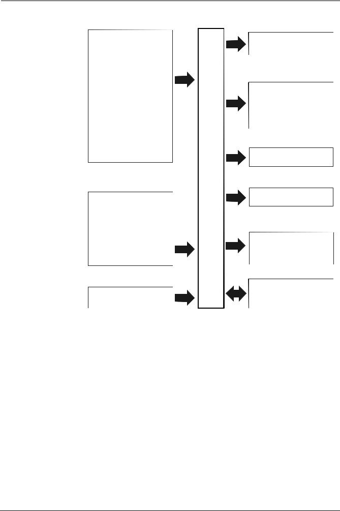
С внешней уставкой

                                      Код конфигурации C111 = X1X1

                         С изменением уставки от внешней системы управления

                                      Код конфигурации C111 = X9XX

     Код конфигурации C111 = X9XX
     SCH2= 0.5x (SPH - SPL)
     SCL2= -0.5 x (SPH - SPL)

     Пример:
     SPH= макс. 130° C
     SPL= мин. 30° C
     SCH2= 0.5 x (130 - 30) = 50
     SCL2= -0.5 x (130 - 30) = -50

11
ПРИЛОЖЕНИЕ: ПОДКЛЮЧЕНИЕ ДАТЧИКОВ
Для обеспечения максимального комфорта система регулировки должна иметь надежную информацию, которую можно
получить при условии, что датчики правильно установлены.
Датчики измеряют и передают все изменения, происходящие в месте их установки.
Измерение осуществляется на базе конструктивных характеристик (постоянная времени) и в соответствии с точно
определенными условиями эксплуатации.
Для представленных электрических подключений необходимо заглушить оболочку (или трубку) с проводами рядом с
клеммником датчика с тем, чтобы поток воздуха не влиял на измерение датчика.
Комнатные датчики (или комнатные термостаты)
Монтаж
Комнатные датчики (или термостаты) должны
размещаться в помещении в таком положении, чтобы
обеспечивать измерение фактической температуры без
воздействия внешних факторов..

                                                       Погодные датчики
                                                       Монтаж
                                                       В системах отопления или кондиционирования, в которых
                                                       предусматривается компенсация в зависимости от
                                                       внешней температуры, расположение датчика имеет
                                                       основополагающее значение.

Установка для красоты – хорошо, но лучше, чтобы
обеспечивалась эффективность
Отопительные системы: комнатный датчик не должен
устанавливаться в помещениях с нагревающими
приборами с термостатами.
Избегать всех источников тепла, не относящихся к
установке....

                                                       Общее правило: на наружной стене здания на уровне
                                                       гостиной, не на фасаде, обращенном на юг или
                                                       находящемся под действием утреннего солнечного
Утюг Телевизор Кухонная плита                          излучения. Если возникают сомнения, устанавливайте
и источников холода, как, например, наружная стена.    датчики на северную или северо-западную сторону.
Расположение                                           Положения, которых следует избегать
на внутренней стене напротив нагревающих приборов
высота от пола 1,5 м
на расстоянии минимум 1,5 м от наружных источников
тепла (или холода)

Монтажные положения, которых следует избегать
рядом со шкафами или нишами
рядом с дверями или окнами                             Не устанавливать рядом с окнами, вентиляционными
на внутренней части наружных стен, находящихся под     решетками, снаружи котельной, на дымовых трубах или
действием солнечного излучения или потоков холодного   под защитой балконов и навесов.
воздуха                                                Датчик не должен окрашиваться (погрешность
на внутренних стенах, через которые проходят           измерения).
трубопроводы системы отопления, горячего
водоснабжения, трубопроводы системы охлаждения

                                                                                                             12
Датчики для установки в канал или трубопровод           Монтаж датчиков давления
Монтаж температурных датчиков                           A. монтаж на трубопроводы для рабочих сред с
Для измерения воздуха на нагнетании:                       температурой макс. 80°C
- после нагнетательного вентилятора или                 B. монтаж на трубопроводы с температурой выше 80°C
                                                           и для хладагентов
- после регулируемого агрегата, расстояние по
  меньшей мере 0,5 м                                    C. монтаж на трубопроводы с высокой температурой:
Для измерения температуры помещения:                    - увеличить длину сифона
                                                        z - располагайте датчик сбоку для предотвращения
- до вентилятора отбора или рядом с отбором из
                                                               прямого попадания на него горячего воздуха из
  помещения
                                                             трубы..
Для измерения температуры насыщения:
- после каплеотделителя

Согните вручную (запрещается использовать                 Монтаж дифференциальных датчиков давления для
инструменты), как показано на рисунке, датчик 0,4 м.      воды
                                                          Не разрешается монтаж с кожухом, обращенным вниз.
                                                          При температуре выше 80°C необходимы сифоны.
                                                          Для предотвращения повреждения датчика необходимо
                                                          проверять
                                                          при монтаже:
                                                          - что разница давления не превышает значения,
                                                             разрешенного для датчика
                                                          - что при наличии высокого статического давления
                                                            включаются отсечные клапаны A-B-C.
                                                          Ввод в эксплуатацию:
Уложите по всему сечению канала, мин. расстояние от       запуск                                   отключение
стенок - 50 мм, радиус закругления - 10 мм для датчиков 2
                                                          1=открыть C                              1=открыть C
или 6 м
                                                          2=открыть A                              2=закрыть B
                                                          3=открыть B                              3=закрыть A
                                                          4= закрыть C
Монтаж комбинированных датчиков влажности
В качестве датчика предела макс. влажности на
нагнетании (паровые увлажнители).

13
Погружные и кольцевые датчики
                                                      Монтаж погружных датчиков
                                                      Датчики должны устанавливаться на участок
                                                      трубопровода, в котором всегда имеется циркуляция
                                                      рабочей среды.
                                                      Жесткий стержень (чувствительный измерительный
                                                      элемент) должен вводиться по меньшей мере на 75 мм в
                                                      направлении, обратном направлению потока.
                                                      Рекомендуемые расположения: на колене или на
                                                      прямолинейном участке трубопровода с наклоном в 45° с
                                                      противотоком относительно направления рабочей среды.
                                                      Обеспечьте защиту от просачивания воды (подтекающие
                                                      затворы, конденсат с трубопроводов и т. д.).

                                                      Монтаж кольцевых датчиков QAD2..
                                                      Обеспечьте наличие циркуляции рабочей среды.
                                                      Удалите изоляцию и окраску (также
                                                      для защиты от ржавчины) на участке трубопровода
                                                      длиной по меньшей мере 100 мм.
                                                      Датчики имеют полосы для труб диаметром макс.
                                                      100 мм.

Расположение датчиков
(QAD22.../QAE21.../QAP21.../RCA...)

С насосами на нагнетании                              Кольцевые или погружные датчики?
                                                      Кольцевые датчики QAD2…
  с 3-хходовыми клапанами / с 4-хходовыми клапанами   Преимущества:
                                                      - Постоянная времени 10 с
                                                      - Монтаж на работающую установку (не требуются
                                                        гидравлические работы)
                                                      - Положение монтажа, если оно окажется
                                                        неправильным, может легко меняться.

                                                      Недостатки:
       панельная установка / управление горелкой      - Пригоден для труб макс. 100 мм
                                                      - На работу могут оказывать влияние потоки
                                                        воздуха и т. д.

                                                      Погружные датчики QAE2...
                                                      Преимущества:
                                                      - Измерение “средней” температуры рабочей
                                                        среды
                                                      - Отсутствие внешних воздействий на измерение, а
С насосами на возврате
                                                        именно: потоков воздуха, находящихся рядом
                                                        трубопроводов и т. д.
  с 3-хходовыми клапанами / с 4-хходовыми клапанами
                                                      Недостатки:
                                                      - Постоянная времени с оболочкой 20 с
                                                      z - Трудность в изменении положения монтажа, если
                                                            оно окажется неправильным.

                                                                                                          14
Датчики и реле давления для установки в канал
 Монтаж датчиков дифференциального давления для                            Базовые принципы
                      воздуха
                                                        Измерение статического давления
                                                           (т. е. давления, оказываемого воздухом на стенки
                                                                             трубопровода)

              A. контроль фильтра (забивание)

                                                                 Измерение динамического давления

             B. контроль вентилятора (до/после)
                                                        Измерение обозначения
                                                        y       кг/м , плотность воздуха
                                                                   3

                                                        θ?      м/с, скорость воздуха
                                                        g      9,81 м/с , ускорение свободного падения
                                                                       2

                                                        Pd   мм водного столба, динамическое давление

                                                        Измерения суммарного давления
                                                        Соответствует алгебраической сумме статического и
                                                        динамического давления

 C. измерение разницы давления между двумя каналами

        D. измерение разницы давления между двумя
     помещениями или между давлением внутри и снаружи
                          канала

                    Подключение датчика давления Siemens QBE 620 P... к клеммнику горелки

                      ДАТЧИК ДАВЛЕНИЯ                                   КЛЕММНИК ГОРЕЛКИ

          белый

         зеленый

       коричневый

15
ПЕРЕЧЕНЬ КОДОВ ДЛЯ ЗАКАЗА

                                 Наименование                           Код
         Модулятор RWF40.000                                           2570112
         Рамка для перехода Siemens ARG40 с RWF32.. на RWF40           2570113
         Датчик температуры Siemens QAE22A (30ч130°C)                  2560101
         Датчик температуры Siemens QAM22 (-15ч+50°C)                  2560135
         Терморезистор Pt1000 ш10 мм L200 мм (0ч350°C)                 2560103
         Датчик давления Siemens QBE2..P4(0ч4 бар / 0ч10V)             2560159
         Датчик давления Siemens QBE2..P10 (0ч10 бар / 0ч10V)          2560160
         Датчик давления Siemens QBE2..P16 (0ч16 бар / 0ч10V)          2560167
         Датчик давления Siemens QBE2..P25 (0ч25 бар / 0ч10V)          2560161
         Датчик давления Siemens QBE20.. P40 (0ч40) бар 25             2560162
         Датчик давления Danfoss MBS 3200 p 1,6 (0ч1,6 бар / 4ч20mA)   2560189
         Датчик давления Danfoss MBS 3200 p 10 (0ч10 бар / 4ч20mA)     2560190
         Датчик давления Danfoss MBS 3200 p 16 (0ч16 бар / 4ч20mA)     2560191
         Датчик давления Danfoss MBS 3200 p 25 (0ч25 бар / 4ч20mA)     2560192
         Датчик давления Danfoss MBS 3200 p 40 (0ч40 бар / 4ч20mA)     2560193
         Термопара типа K ш10 мм L200 мм (0ч1200°C)                    2560142
         Терморезистор Pt100 ш10 мм L200 мм (0ч350°C)                  2560145

                                                                                 16