- Manuals
- Brands
- Saab Manuals
- Measuring Instruments
- TankRadar PRO
- User manual
-
Contents
-
Table of Contents
-
Troubleshooting
-
Bookmarks
Quick Links
Related Manuals for Saab TankRadar Pro
Summary of Contents for Saab TankRadar Pro
-
Page 1
User´s Guide… -
Page 2
Saab TankRadar ® User´s Guide Second edition Copyright © September 1998 Saab Marine Electronics AB Edition 2. Ref. No: 306010E… -
Page 3
Saab Tank Control will not take any responsibility for faults, accidents, etc caused by non-recognized spare parts or any repair which is not made by Saab Tank Control. Specific FCC Requirements (USA only) This device complies with part 15 of the FCC Rules. -
Page 4: Table Of Contents
Saab TankRadar ® Contents About this manual …………vii 1 Introduction…………1-1 The TankRadar Pro System …………1-1 Measurement Principle…………..1-3 2 Mechanical Installation ……… 2-1 Socket Requirements …………..2-1 Free Space Requirements …………. 2-2 Dimensions………………2-3 Tools………………..2-3 Mounting the Rod Antenna …………2-4 Tank flange diameter = 50 mm (2”) ……….
-
Page 5
Saab TankRadar ® Connecting to a TRL2 Bus Interface ……….3-6 Connecting HART devices …………3-7 Active output (internal loop supply) ……….3-7 Passive output (external loop supply)……….. 3-7 Intrinsically safe conditions …………3-8 Non-Intrinsically safe conditions ……….. 3-8 Connecting the Display Panel …………3-9 Cables ………………. -
Page 6
Saab TankRadar ® Setting measurement units …………4-7 Installing a Pro Transmitter …………4-8 Setting a general amplitude threshold ……..4-26 Creating a customized noise threshold table……4-26 Registration of False Echoes …………. 4-29 Viewing Level Data …………..4-33 Service ………………4-34 5 Using the Pro Display Panel……… -
Page 7
Saab TankRadar ® Display Panel……………… 7-3 Analog Outputs …………….7-3 8 Troubleshooting ………… 8-1 Display Panel Error Messages …………8-2 User Input Errors …………….8-2 Internal Software Errors …………… 8-2 Edition 2. Ref. No: 306010E… -
Page 8: About This Manual
The main purpose of the book is to act as guide to installing and operating a TankRadar Pro gauge. It is not intended to cover service tasks such as changing circuit boards or internal software.
-
Page 9
Saab TankRadar ® viii Edition 2. Ref. No: 306010E… -
Page 10: Introduction
The TankRadar Pro System The TankRadar Pro gauge offers a high degree of flexibility. It can be used as a stand-alone unit, or it can be connected to various control systems. You can integrate TankRadar Pro in your own Local Area Network (LAN).
-
Page 11
As an option, your TankRadar Pro gauge can be equipped with an easy-to- use display panel. It offers basically the same functionality as the Pro Setup software package. -
Page 12: Measurement Principle
Saab TankRadar ® Introduction Measurement Principle The Saab TankRadar Pro transmitter sends a microwave signal with a con- tinuously varying frequency towards the liquid surface. When the reflected signal returns to the antenna, it is mixed with the outgoing signal. Transmitted…
-
Page 13
Saab´s echofixer provides a technique to adapt measurements to various situations, by using information from previous measurements. To further improve measurement accuracy, Saab TankRadar Pro can utilize the benefits of Saab´s Fast High Accuracy Signal Technique™ (FHAST™). -
Page 14: Mechanical Installation
Saab TankRadar ® Mechanical Installation 2 Mechanical Installation For optimum measurement performance the TR Pro gauge should be mounted according to the socket requirements and the free space requirements illustrated below. Socket Requirements In order to allow the microwaves to propagate freely, the socket dimensions should be kept within the specified limits for differ- ent antenna sizes.
-
Page 15: Free Space Requirements
Saab TankRadar ® Mechanical Installation Free Space Requirements Position the gauge in a way that allows the microwaves to propa- gate without disturbance from the tank wall, according to the illustration below. Service space 550 mm Maximum angle: • Cone antenna: 1°…
-
Page 16: Dimensions
92 mm (4” cone antenna) 140 mm (6” cone antenna) 188 mm (8” cone antenna) Tools The following set of tools is needed for installation of a TankRadar Pro gauge: • Screw driver • Adjustable wrench • Dispenser for retaining rings •…
-
Page 17: Mounting The Rod Antenna
Saab TankRadar ® Mechanical Installation Mounting the Rod Antenna Make sure that all parts are clean and dry when mounted. 1. Put a gasket on the socket Gasket and insert the antenna. Loose flange 2. Mount the loose flange and tighten the screws.
-
Page 18
Saab TankRadar ® Mechanical Installation Flange adapter 1. Carefully center the flange adap- ter on top of the tank flange. Use gaskets under and above the flange adapter. Flange 2. Insert the antenna into the socket. Mount the loose flange and tighten the screws. -
Page 19: Mounting The Cone Antenna — Ptfe Sealing
Saab TankRadar ® Mechanical Installation Mounting the Cone Antenna — PTFE sealing 1. Mount the flange on top of the cone 3. Mount the adapter on top of the plate. sleeve. Make sure that the bottom side of the flange is flat and all parts are Locking ring clean and dry.
-
Page 20
Saab TankRadar ® Mechanical Installation 5. Carefully fit the flange and the 7. Place the protection sleeve on the cone antenna on the tank flange. nozzle. Mount the transmitter head. Check Tighten with screws and nuts. that the guide pins on the adapter… -
Page 21: Mounting The Cone Antenna — Quartz Sealing
Saab TankRadar ® Mechanical Installation Mounting the Cone Antenna — Quartz Sealing 3. Mount the adapter on the sleeve. 1. Mount the flange on top of the cone plate. Make sure that the bottom side of Locking ring the flange is flat and all parts are clean and dry.
-
Page 22
Saab TankRadar ® Mechanical Installation 5. Carefully fit the flange and the 6. Place the protection sleeve on the cone antenna on the tank flange. flange. Tighten with screws and nuts. Mount the transmitter head. Check that the guide pins on the adapter enter the corresponding grooves on the upper wave guide. -
Page 23: Mounting The Cone Antenna — Process Seal
Saab TankRadar ® Mechanical Installation Mounting the Cone Antenna — Process Seal It is very important that the nozzle surface is flat. The maximum deviation must be within the following specifications as illustrated below (see Installation Instruction Process Seal Doc. no. 9240007-985): Concave: Ceramic window: d<0.1 mm…
-
Page 24: Torque
Mechanical Installation To mount the antenna do the following: 1. Place a gasket on top of the socket and mount the antenna. Use one of the two gaskets delivered by Saab: • Teflon • Graphite for temperatures above 250 º C.
-
Page 25
Saab TankRadar ® Mechanical Installation 4. Insert the wave guide tube into the upper wave guide. Wave guide 5. Mount the transmitter head onto the adapter. Wave guide tube 6. Tighten the nut and make sure that the transmitter head fits tightly to the antenna. -
Page 26
Saab TankRadar ® Mechanical Installation Attach the flange screws by using the following recommended torque values: » 4 » 6 » 4 » 6 Table 1. Recommended torque for flange screws. 2-13 Edition 2. Ref. No: 306010E… -
Page 27: Mounting The Parabolic Antenna
Saab TankRadar ® Mechanical Installation Mounting the Parabolic Antenna Flange 1. Mount the flange on top of the antenna feeder. Use the screws and nuts delivered with the unit. Make sure that the guide pin at the bottom side of…
-
Page 28
Saab TankRadar ® Mechanical Installation Flange 3. Mount the antenna feeder to the tank nozzle. If necessary, use angular rings (inclination device) to align the antenna within ±0.5 . The rings can be used if the tank nozzle flange is horizontal within ±4… -
Page 29
Saab TankRadar ® Mechanical Installation 5. Mount the TCP tube into the TRL2 tube adapter. TRL2 adapter 6. Mount the transmitter head. Rotate the head and the TRL2 adapter to align the cover locking at the back of the transmitter head with the guide pins. -
Page 30: Electrical Installation
Saab TankRadar ® Electrical Installation 3 Electrical Installation Approval Identication of Cenelec Installed Options Other certificates II Power Supply 100 — 240 VAC nominal power I II III IV V 24 -48 VDC nominal power Approval III Primary Output Power Supply…
-
Page 31: Junction Box
Saab TankRadar ® Electrical Installation Junction Box The standard version is equipped with a junction box that con- sists of a non-intrinsically safe and an intrinsically safe part. There is also an optional version with two non-intrinsically safe compartments. Flameproof enclosure…
-
Page 32: External Connections
Saab TankRadar ® Electrical Installation External Connections This Junction Box is for non-intrinsically safe connections and power supply. EExe 1-2 Non-intrinsically safe HART/4-20 mA primary analog output, TRL/2 Bus 3-4 Power supply input Not connected Electrical safety ground terminal Note: redundant when the transmitter is grounded according to CENELEC.
-
Page 33
Saab TankRadar ® Electrical Installation This Junction Box is for intrinsically safe connections and for connection of the Display Panel. EExi 1-2 Intrinsically safe HART/4-20 mA primary analog output. 3-4 Secondary analog output. 5-6 Display panel. Ground terminal for Display Panel. -
Page 34
Saab TankRadar ® Electrical Installation This is the standard intrinsically safe Junction Box (EExi) fitted with an alternative connector for connection of non-IS output if required. EExi/e 1-2 Not used 3-4 Non-intrinsically safe Secondary Analog Output Not connected Ground terminal (not used) Cable shield Connect the shield to the cable glands. -
Page 35: Connecting To A Trl2 Bus Interface
Saab TankRadar ® Electrical Installation Connecting to a TRL2 Bus Interface Use a Field Bus Modem (FBM) for a Pro transmitter equipped with a TRL2 interface. Field Bus Modem Connect to the non-intrinsically safe junction box (EEx e). Junction Box EEx e…
-
Page 36: Connecting Hart Devices
Saab TankRadar ® Electrical Installation Connecting HART devices Junction Box For Pro gauges with active EEx e Input impedance output a hand-held terminal or <300 Ohm a HART modem can be con- nected as follows: 7 8 9 4 5 6…
-
Page 37
Saab TankRadar ® Electrical Installation A hand-held HART communicator can be connected in the hazardous area. The HART interface must be connected via a zener barrier in the safe area. Hazardous Area Non-Hazardous Area RTG 40 HART Analog instrument Zener… -
Page 38: Connecting The Display Panel
Saab TankRadar ® Electrical Installation Connecting the Display Panel The Display Panel is intrinsically safe and may only be used when permanently mounted directly on the enclosure with two separate grounding wires. There are four wires to be connected to the X2 terminal: •…
-
Page 39: Cables
(AWG 20) for analog outputs and serical communication. Safety The TankRadar Pro enclosure is flame- proof and may not be opened while the transmitter is energized and a flammable atmosphere is present. Saab Tank Con- trol will not take any responsibility for…
-
Page 40: System Overview
Extra Analog EEx i Output EExi junction box for intrinsically safe (XA40 + IS40) applications. Saab TankRadar Pro can be equipped ® HART with HART interface or Saab TRL/2 Interface Bus interface. HART modem +…
-
Page 41: Internal Connections
Saab TankRadar ® Electrical Installation Internal Connections Non-Intrinsically Safe (EEx e) Intrinsically Safe (EEx i) Option Description Board DC40 100 — 240 VAC AC40 24 — 48 VDC DC40 AC40 IS Gnd Option Description Board DI40 No Display Panel Display Panel…
-
Page 42
Saab TankRadar ® Electrical Installation Non-Intrinsic Safety (EEx e) Option Description Board TM40 Non-intrinsically safe HM40+IS40 HART/4-20 mA, HM40 active. HM40 Non-intrinsically safe HM40 HART/4-20 mA, passive IS40 TRL2 Bus TM40 Intrinsic Safety (EEx i) IS Gnd Option Description Board… -
Page 43
Saab TankRadar ® Electrical Installation Intrinsic Safety (EEx i) Option Description Board IS Gnd XA40 Intrinsically Safe XA40+IS40 4-20mA active Intrinsically Safe XA40 XA40 4-20mA passive IS40 Non-Intrinsic Safety (EEx e) Option Description Board XA40 Non-intrinsically safe XA40+IS40 4-20mA active… -
Page 44: Pro Setup Software
RTG 40 Modem It is a simple task to start and configure the TankRadar Pro trans- mitter. When the gauge is mounted on the tank flange, and the cables are properly connected you only need to run through a straightforward configuration procedure to start the transmitter.
-
Page 45: System Requirements
Hard disk space: 5 MB Installing the Pro setup software To install TankRadar Pro configuration software on your compu- ter do the following: Start Windows and make sure that no applications are running. If you run Pro Setup under Windows 95, upgrade Windows 95 by running the Dcom95.exe upgrade kit.
-
Page 46
Saab TankRadar ® Pro Setup Choose installation directory. Program FilesSaab is the default directory. Click the Browse button if you want to specify another installation directory. Click the Next button. 5. Follow the instructions in the installation wizard. Click the Next button. -
Page 47
Saab TankRadar ® Pro Setup Specify the Com port and communication protocol you will use to connect the gauge. Com port and protocol can be changed later. Finish the installation. Edition 2. Ref. No: 306010E… -
Page 48: Starting The Pro Setup Program
Note! While Pro Setup is running, the Win95 Task Bar contains two buttons named “Pro Setup” and “Saab TankRadar IO Master Server” .The last button refers to a communication program support- ing Pro Setup. Normally, you do not need to open this window unless you need to change communication parameters.
-
Page 49: Setting A Password
Saab TankRadar ® Pro Setup Setting a Password You can set a password to prevent unauthorized changes of the transmitter configuration. Then you will have to enter the pass- word in order to obtain access to configuration and service op- tions.
-
Page 50: Logging On To A Password Protected System
Saab TankRadar ® Pro Setup Logging on to a password protected system. To log on to a password protected system do the following: Select Password from the Setup menu. Enter your password in the Password input field. Click the Log On button.
-
Page 51: Installing A Pro Transmitter
Installing a Pro Transmitter Do the following to install and configure a Pro transmitter: Connect to a TankRadar PRO transmitter. Select New Tank from the File menu in the Main window. Enter a tank name to associate with the tank and click the OK button.
-
Page 52
Electrical Installation ). — or — • Choose Saab Modbus if your gauge is equipped with a TRL/2 Bus interface. Make sure that you select the same protocol that was specified during the Pro Setup installation. -
Page 53
Note! For Modbus devices the scan may be very time consuming if the default address is still valid. Normally the scan starts at address 0 for HART buses and address 1 for Saab Modbus. You can enter other start addresses in the Address field in order to reduce the scanning time. -
Page 54
Saab TankRadar ® Pro Setup Select the Start Radar tab Click the Read button. Response: the current settings and the Start Code are displayed. Check that the correct set of available options is displayed. Contact your local representative if you like to add one or more of the follow- ing software options: EchoFixer, MET, FHAST filtering or strap table volume calculations. -
Page 55
Saab TankRadar ® Pro Setup In the Tank Environment and Presentation Standard tab there are two groups of parameters. In the Environment box mark the check boxes that correspond to the conditions in your tank: Rapid level changes optimizes the transmitter for measurement conditions where the level changes quickly due to filling and emptying of the tank. -
Page 56
Saab TankRadar ® Pro Setup restricted to a region close to the tank bottom (Related database register: Full tank detection area, 1516 ). Do not set this parameter if the bottom echo is not visible. Slow Search This variable controls how to search for the surface if a surface echo is lost. -
Page 57
Saab TankRadar ® Pro Setup Tank Environment See description of the Tank Environment parameters in the Standard tab. Note! The Tank Environment parameter settings overrides some of the Holding register settings. Tank Obstacles This option is not used in the current version of the Pro application software. -
Page 58
Saab TankRadar ® Pro Setup Tank Presentation Level above min If the surface echo is lost in the vicinity of distance possible the antenna, full tank is indicated and searching for the surface echo is limited to a region close to the antenna. -
Page 59
Saab TankRadar ® Pro Setup solved by changing the mechanical instal- lation. Related database register: DoubleBounceOffset (1522). Slow search See description of the Standard tab pa- rameters. Related database register: SearchSpeed (1524). Double surface Indicates that there are two liquids in the tank resulting in two reflecting surfaces. -
Page 60
Saab TankRadar ® Pro Setup Invalid level is not set If the surface echo is lost close to the top if tank is full or empty or close to the bottom of the tank, the level value full/empty will normally be displayed as “invalid”. -
Page 61
Saab TankRadar ® Pro Setup Select the Configuration tab Click the Read button. Response: the current settings are displayed. In the Tank Geometry box, enter values for Distance Offset (G), Tank Height (R) and Minimum Level Offset (C). The Distance Offset (G) is defined as the distance between the upper reference point and the flange ( the flange is referred to as the Tank Radar Pro Reference Point) . -
Page 62
Saab TankRadar ® Pro Setup the distance between the zero level and the tank bottom. Set C=0 if you use the tank bottom as zero reference point. The Hold Off (H) distance defines how close to the TR Pro refer- ence point a level value is accepted. -
Page 63
Saab TankRadar ® Pro Setup Select the Analog Outputs tab Click the Read button. Response: the current settings are displayed. ® If your transmitter is equipped with a HART modem select the Analog Out1 tab. (Analog 1 is note available when using TRL2 Bus communication). -
Page 64
Saab TankRadar ® Pro Setup Calibrating the Digital to Analog Converter (DAC) The Digital to Analog Converter (DAC) is factory calibrated. How- ever, if you want to check the calibration by measuring the output current, do the following: Click the Calibrate DAC… button. -
Page 65
Saab TankRadar ® Pro Setup Click the Set to 20 mA button. Enter the measured output current and click the Store button. Click the Cancel button to close the window and finish the calibra- tion. 4-22 Edition 2. Ref. No: 306010E… -
Page 66
The strap- ping table is an optional function. If it is not available a new Start Code can be ordered from Saab Tank Control. To enable Strapping Table select the corresponding option in the Pro Setup/Volume window. -
Page 67
Saab TankRadar ® Pro Setup Ideal tank Use this option if approximation of your tank with an ideal tank shape provides sufficient accuracy. Enter the follwoing parameters: • Tank diameter (or the length if it is a horizontal tank). • “Distance between zero volume and zero level mark”: set this parameter if you do not want zero volume and zero level to match (for example if you want to include volume below the zero level). -
Page 68
Saab TankRadar ® Pro Setup Disturbance Echo Handling Pro Setup offers you powerful tools to handle disturbing echoes. The False Echo tab displays a list of echoes detected by the Pro transmitter. To optimize measurement performance you can register false echoes which are due to disturbing objects in the tank like beams, agitators and heating coils. -
Page 69
Saab TankRadar ® Pro Setup Click the Read button General amplitude threshold Response: a spectrum is displayed showing the radar amplitude vs. distance from the gauge to the product surface (ullage). Set the general Amplitude Threshold. Echoes with amplitudes below the general amplitude threshold will be disregarded. Recom- mended threshold value: Calm conditions: no turbulence, foam or condensation. -
Page 70
Saab TankRadar ® Pro Setup Add button To add points to the diagram: Place the mouse pointer in the diagram at the position where you want to add a point to the Amplitude Threshold curve. Click the right-hand mouse button and… -
Page 71
Saab TankRadar ® Pro Setup The following examples illustrate how the Amplitude Threshold table can be used: Example 1: The amplitude threshold is used to remove the influence from the tank nozzle. Influence from pipe inside the tank Influence from… -
Page 72
In order to optimize the measurement performance, you may need to register interfering echoes as described below. Note! Registration of disturbing echoes requires that Saab´s echofixer is enabled. When should I register? See the following recommendations before you register new interfering echoes: •… -
Page 73
Saab TankRadar ® Pro Setup • Make sure that the level is stable before you register a disturbance echo. A fluctuating level may indicate a temporary disturbance which is not due to an interfering object. • Do not register a disturbing echo if the amplitude is below the general amplitude threshold, see description of the Spectra-Thresh- old window. -
Page 74
Saab TankRadar ® Pro Setup To register interfering echoes do the following: Select an echo from the list of Interfering Echoes. Echo to be registered Click the Add Echo button. Add Echo Response: the echo is displayed in the table of Registered echoes. -
Page 75
Saab TankRadar ® Pro Setup To manually add items to the list of registered disturbing echoes You can manually enter disturbing echoes which are not present in the list of automatically detected echoes. This function can be useful if there are objects below the product surface which can not be detected by the gauge at the time of installation. -
Page 76: Viewing Level Data
Saab TankRadar ® Pro Setup Viewing Level Data To view level data do the following: 1. Start the Pro Setup program. 2. Open a tank file by choosing Open Tank from the File menu by clicking the Open Tank button.
-
Page 77: Service
Searching for the Product Surface Select this option if you want to initiate a search for the product surface without restarting the transmitter. Restarting TR Pro Select this option if you need to restart the TankRadar Pro trans- mitter. 4-34 Edition 2.
-
Page 78: Using The Pro Display Panel
• The Service option allows you to view configuration status, edit holding registers, reset holding registers to factory values, do a software reset or to start a search for the surface echo. • The Setup option allows you to configure a TankRadar Pro transmitter. Edition 2.
-
Page 79
Saab TankRadar ® Pro Display Panel The LCD contrast can be increased by simultaneously Level 24.500 pressing the two buttons on the right-hand side. Press MENU ITEM GRPH the two left-hand buttons to decrease the contrast. It takes approximately 10 seconds to adjust from minimum to maximum display panel contrast. -
Page 80: Softkeys
Saab TankRadar ® Pro Display Panel The softkeys have different meanings depending on which win- dow that is open. Use the arrow buttons to move the cursor up and down (or sideways in some windows). These buttons are also used for changing figures when you are asked to enter a value.
-
Page 81
Saab TankRadar ® Pro Display Panel When viewing measurement data, you can use the softkeys to move between different views as illustrated below. There are also status indicators showing you that measurements are performed, and whether these measurements are valid or not. -
Page 82
Saab TankRadar ® Pro Display Panel When you configure TankRadar Pro, the softkeys will take on definitions which allow you to select specific items and to save the choice. When the cursor has reached the last item, it jumps back to the first item by pressing the button. -
Page 83
Saab TankRadar ® Pro Display Panel Use the button to enter the desired value. Each click in- creases the digit value one step from zero to nine and back to zero. Use the button to move the cursor to the next digit. When… -
Page 84: Viewing Level Data
Saab TankRadar ® Pro Display Panel Viewing Level Data The View Menu includes options for viewing tank and gauge related data: VIEW MENU Display Standard Data BACK NEXT • Press the button to return to the Main menu. BACK • Use the…
-
Page 85
Saab TankRadar ® Pro Display Panel Display L e v e l Select the Display submenu to view measured data: Press the ITEM button to choose between the different options: MENU ITEM GRPH • Level • Ullage • Level Rate •… -
Page 86: Installing A Pro Transmitter
Saab TankRadar ® Pro Display Panel Installing a Pro Transmitter Select Setup from the Main Menu and choose one of the options to configure the transmitter. MAIN MENU View… Service… Setup… NEXT The Setup dialog is automatically opened when a transmitter is started for the first time.
-
Page 87
Saab TankRadar ® Pro Display Panel Use this option to set presentation units, language and password. If you do not want to change the default settings, you can skip this step and go to Guided or Advanced Setup. To configure the display panel do the following: . -
Page 88
Saab TankRadar ® Pro Display Panel The Guided Setup includes the basic steps to start the transmit- ter. By using this option you are guided step by step through a se- quence of configuration windows. The windows are automati- cally opened in a predefined order. -
Page 89
4 8 1 A 7 0 E 9 7 0 5 1 5 9 F 2 code that enables the ordered software options. If you wish to change the set of available options, (Saab´s echofixer, Mul- tiple Echo Tracking™ (MET), Fast High Accuracy Signal Technique™ (FHAST) and strapping table volume calculation), contact your local representative for a new start code. -
Page 90
Saab TankRadar ® Pro Display Panel O f f s e t D i s t ( G ) G>0 i s t h e d i s t a n c e f r o m d i p p i n g m a r k t o T R P r o r e f . -
Page 91
Saab TankRadar ® Pro Display Panel Use the Advanced Setup if you want to make a complete con- figuration of the transmitter: 5-14 Edition 2. Ref. No: 306010E… -
Page 92
Saab TankRadar ® Pro Display Panel To configure a radar gauge using the Advanced Setup option: . Choose Setup from the Main Menu. Response: a request for password is displayed. Give password: . Enter your password and press the button. -
Page 93
4 8 1 A 7 0 E 9 7 0 5 1 5 9 F 2 code that enables the ordered software options. If you wish to change the set of available options, (Saab´s echofixer, Multiple Echo Tracking™ (MET), Fast High Accuracy Signal Technique™… -
Page 94
Saab TankRadar ® Pro Display Panel Choose the Tank Environment option. Select appropriate surface condi- tions. Mark the options that de- scribes the conditions in your tank by using the button. You MARK should not choose more than two options for best performance. Press… -
Page 95
Saab TankRadar ® Pro Display Panel . Select the Calibration option from the Advanced Setup menu. G>0 G<0 The tank calibration distances are defined as illustrated on the next page. Set the Distance Offset (G). The Distance Offset is defined as the distance between the upper reference point and the flange ( the flange is referred to as the Tank Radar Pro Reference Point) . -
Page 96
Saab TankRadar ® Pro Display Panel Note! See chapter Tank Distances for further information on how to set the tank geometry parameters. The following steps are only applicable when a non-standard antenna is used. Set the Holdoff Distance (H). The Hold Off distance defines how close to the RTG reference point a level value is accepted. -
Page 97
Saab TankRadar ® Pro Display Panel . Select the Analog output1 option from the Advanced Setup menu (Optional). If the gauge is equipped with an analog output, the range of the output is automatically calibrated to match the tank calibration (G and R). -
Page 98
Saab TankRadar ® Pro Display Panel DA Trim AOut 1 Enter meter value 4000 µA DONE Enter the measured value that corresponds to the 4 mA setting. Click the DONE button. Response: the analog output is set to 20 mA. -
Page 99
Saab TankRadar ® Pro Display Panel . Select the False Echo option from the Advanced Setup menu (optional). In normal operation the gauge compares FALSE ECHO detected echoes with a list of registered Tank Echoes disturbance echoes, in order to decide wich Reg. -
Page 100
Saab TankRadar ® Pro Display Panel REG. FALSE ECHOES 0.56 m 8.45 m 14.20 m 15.37 m 32.00 m EDIT CNCL To remove a registered disturbing echo, do the following: Move the cursor to the echo you want to remove. -
Page 101
Saab TankRadar ® Pro Display Panel . Select the Volume option from the Advanced Setup menu (optional). The Volume option allows you to setup the Pro transmitter for volume calculations. You can choose between using either a predefined tank shape like a sphere or a… -
Page 102: Service
The service functions should only be used if you are familiar with the advanced functionality of TankRadar Pro. Config Report Shows information on antenna type, software versions, software and hardware configuration, operation time, error status and unit code.
-
Page 103
Saab TankRadar ® Pro Display Panel 5-26 Edition 2. Ref. No: 306010E… -
Page 104: Tank Distances
Saab TankRadar ® Tank Distances 6 Tank Distances Definitions The Distance Offset (G) is defined as the distance between the upper reference point and the flange (the flange is referred to as the Tank Radar Pro Reference Point). You can use G to specify your own reference point at the top of the tank.
-
Page 105
Saab TankRadar ® Tank Distances The Tank Height (R) is defined as the distance between the upper reference point (specified by the Distance Offset G) and the lower reference point (zero level). If no datum plate or zero level exist the tank bottom usually is used as zero reference point. -
Page 106: Examples
Saab TankRadar ® Tank Distances Examples The following examples illustrate how you can set the various tank distance parameters to suit your own preferred reference point settings. Example 1 If you want Upper reference point at G=distance between the tank roof flange and tank roof (G<0).
-
Page 107
Saab TankRadar ® Tank Distances Example 2 If you want Upper reference point equal to the TR Pro reference point Lower reference point at R=distance between TR Pro the bottom of the tank reference point and the bottom of the tank C=0. -
Page 108
Saab TankRadar ® Tank Distances Example 3 If you want Upper reference point at the G=distance between ullage ullage reference point and RTG reference points. Lower reference point at the tank bottom R=distance between ullage reference point and tank bottom. -
Page 109
Saab TankRadar ® Tank Distances Example 4 If you want Upper reference point G=distance between ullage at ullage reference point and RTG reference points. Lower reference point at R=to distance from ullage datum plate reference point to datum plate. C=distance between datum plate and tank bottom. -
Page 110: Technical Information
Saab´s Echofixer and echo handling Multiple Echo Tracking Level output Display panel, analog 4-20 mA signal with digital HART, serial Saab TRL/2 Bus Ex approval Transmitter Head CENELEC: (Standard and Gold versions) EEx de [ib] IIC T6. Explosion proof Class I, Div. I & 2, Groups A, B, C and D.
-
Page 111
, SS 316L/HC4/Tantalum, Viton/ Kalrez ® Dimensions 545 (H) x 200 (W) mm (4” cone) Weight 8 kg Height above flange 400 mm (15”) Water protection IP 65 Serial communication HART or Saab TRL/2 Bus Edition 2. Ref. No: 306010E… -
Page 112
Saab TankRadar ® Technical Information Display Panel • For presentation of measured values and configuration of the transmitter • Graphical LCD display 128 x 64 pixels • Four softkeys • Text: 7 lines with 16 characters • Graphics up to 128 X 56 pixels •… -
Page 113
Saab TankRadar ® Technical Information Edition 2. Ref. No: 306010E… -
Page 114: Troubleshooting
Saab TankRadar ® Troubleshooting 8 Troubleshooting SYMPTOM ACTION No level reading Check the power supply. Check the cables for serial data commu- nication. Incorrect level reading Check the transmitter calibration. Check that the transmitter has not locked on an interfering object.
-
Page 115: Display Panel Error Messages
Saab TankRadar ® Troubleshooting Display Panel Error Messages This message appears if you try to enter an unvalid value into a holding register. C a l i b r a t e u l l a g e b y s e t t i n g t h e…
-
Page 116
Saab Tank Control Local Representative: Saab Tank Control Phone: + 46 31 337 00 00 Box 13045 Fax: + 46 31 25 30 22 S-402 51 Göteborg e-mail: sales.stc@marine.combitech.se SWEDEN Internet: http://www.saab.tankradar.com…
-
Contents
-
Table of Contents
-
Troubleshooting
-
Bookmarks
Quick Links
SERVICE MANUAL
MaC — Monitoring and Control System
Summary of Contents for Saab TankRadar G3
-
Page 1
SERVICE MANUAL MaC — Monitoring and Control System… -
Page 2: Documentation For Saab Tankradar
Saab Marine Electronics AB takes no responsibility for any errors that may appear in this manual. As each TankRadar G3 is specially designed for each delivery, the con- tents and illustrations in this manual may differ from your TankRadar G3 system.
-
Page 3: Table Of Contents
Contents Documentation for Saab TankRadar …………….. 2 Training ……………………… 2 www.saab.tankradar.com ………………..2 Abbreviations …………….5 System overview …………….7 Equipment in the I/O Unit cabinet ………..9 I/O Terminal Analog Input -description …………..9 LED´s …………………………. 9 Fuses ………………………….. 9 I/O Terminal Analog Output — description …………10 LED´s …………………………
-
Page 4
Service Manual Maintenance …………….19 Trouble shooting …………..21 Spare Parts …………….23 Recycling of Saab TankRadar………..25 Give us your opinion!…………..27 G3 MaC Second edition, March 2000… -
Page 5: Abbreviations
1 Abbreviations Abbreviations Light Emitting Diode Printed Circuit Board Power Supply Work Station G3 MaC Second edition, March 2000…
-
Page 6
Service Manual G3 MaC Second edition, March 2000… -
Page 7: System Overview
Valve control Pump control Safe area system (not system (not Saab supply) Saab supply) Temperature Pressure Valves sensors sensors Hazardous area Cargo or ballast pumps Figure 2-1 An example of a Saab TankRadar MaC system. G3 MaC Second edition, March 2000…
-
Page 8
Service Manual G3 MaC Second edition, March 2000… -
Page 9: Equipment In The I/O Unit Cabinet
3 Equipment in the I/O Unit cabinet Equipment in the I/O Unit cabinet I/O Terminal Analog Input — description Figure 3-1 above. The large type of I/O Unit. Figure 3-2 right. The I/O Terminal Analog Input. Fuse LED, power Connector (Power and Communication) LED, ground Failure LED, communication Address Switches…
-
Page 10: I/O Terminal Analog Output — Description
Service Manual I/O Terminal Analog Output — description Figure 3-3 The I/O Terminal Analog Output. Fuse LED, power Connector (Power and Communication) LED, ground Failure LED, communication Address Switches Jumpers (channel settings) Channel Switches (connected/disconnected) Cable terminal LED´s Power (green) The lit LED indicates that the terminal has power.
-
Page 11: I/O Terminal Digital Input — Description
3 Equipment in the I/O Unit cabinet I/O Terminal Digital Input — description Figure 3-3 The I/O Terminal Digital Input. LED, power Connector (Power and Communication) LED, ground Failure LED, communication Address Switches Channel Switches (connected/disconnected) Cable terminal LED´s Power (green) The lit LED indicates that the terminal has power.
-
Page 12: I/O Terminal Digital Output — Description
Service Manual I/O Terminal Digital Output — description Figure 3-3 The I/O Terminal Digital Output. LED, power Connector (Power and Communication) LED, communication Address Switches LED, relays Cable terminal LED´s Power (green) The lit LED indicates that the terminal has power.
-
Page 13: I/O Terminals In I/O Unit — Service
Terminal Main Block turns off the power in the I/O Unit. In the Saab TankRadar I/O Unit, turn off the power by turning the automatic fuse switch on the I/O Terminal Main Block to the off position. Disconnect the connector (power and communication) from the terminal.
-
Page 14: Power Supply In I/O Unit — Description
Service Manual Connect the connector (power and communication) to the terminal. Turn on the power on the I/O Terminal Main Block. Power supply in I/O Unit — description Led, Power Figure 3-5 The Power Supply in the I/O Unit. LED´s DC ON (green) The lit LED indicates that the Power is on…
-
Page 15: Power Supply In I/O Unit — Service
3 Equipment in the I/O Unit cabinet Power supply in I/O Unit — service To replace a Power Supply In the Saab TankRadar I/O Unit, turn off the power by turning the automatic fuse switch on the I/O Terminal Main Block to the off position.
-
Page 16: I/O Terminal Main Block — Description
Service Manual I/O Terminal Main Block — description Figure 3-7 The automatic fuse switches on the I/O Terminal Main Block turns off the power in the I/O Unit. Automatic fuse Fuse The I/O Terminal Main Block have two automatic fuses that also are used to shut down the I/O Unit.
-
Page 17: O Terminal Multiplexer
4 I/O Terminal Multiplexer I/O Terminal Multiplexer Description Figure 4-1 The I/O Terminal Multiplexer. Connector (Power) LED, power LED, communication LED, ground Failure Connector (Communication) Address Switches Cable terminal Channel 1-8 Cable terminal Channel 9-15 LED´s Power (green) The lit LED indicates that the terminal has power.
-
Page 18: Service
Verify the configuration of the address switches by compar- ing with the old motherboard. Put the old terminal in an ESD protection bag for transport to Saab Marine Electronics. Mount the board in the box. Connect the cables to the cable terminal.
-
Page 19: Maintenance
5 Maintenance Maintenance No maintenance is required for the Saab TankRadar MaC system. G3 MaC Second edition, March 2000…
-
Page 20
Service Manual G3 MaC Second edition, March 2000… -
Page 21: Trouble Shooting
Trouble shooting Symptom Cause Action WS Alarm- Ground failure on In the Saab TankRadar I/O Unit , Warning, IO terminal Bus (1-4) gnd one terminal identify the terminals with a lit fail red ground failure LED Check the equipment (pumps,…
-
Page 22
Check if the power supply is functioning Check cabling Replace the Power Supply Broken circuit In the Saab TankRadar I/O Box, between I/O Unit check the communication LED on the RS-485 PCB Refer to as- and I/O Box built drawings to find right PCB… -
Page 23: Spare Parts
7 Spare Parts Spare Parts Spare parts are ordered from Saab Marine Electronics’ After Sales department Part No. Spare part 0980 239-008 Fuse 500 mA 9240 006-801 I/O Terminal Analog Input 9240 006-802 I/O Terminal Analog Output 9240 006-803 I/O Terminal Digital Input…
-
Page 24
Service Manual G3 MaC Second edition, March 2000… -
Page 25: Recycling Of Saab Tankradar
Recycling of Saab TankRadar At a point in time when your Saab TankRadar system has served you well for many years and it is time to scrap the ship Saab Marine Electronics is more than willing to assist you with the recycling of the system.
-
Page 26
Service Manual G3 MaC Second edition, March 2000… -
Page 27: Give Us Your Opinion
Give us your opinion! To produce the best possible product. We design Saab TankRadar in cooperation with you, our customers. We are therefor always interested in hearing your opinion. Please contact us and tell us what you think of this manual and the Saab TankRadar system.
Похожие релизы
| # | Тема | Форум | Автор |
|---|---|---|---|
|
RU |
Правила эксплуатации судового электрооборудования — И.Ихильчик [1987, PDF] |
Библиотека электромеханика | |
|
RU/EN |
Англо-русский и русско-английский словарь морской терминологии — Г.А. Амелин [1998, PDF] |
Словари и разговорники RU↔EN | borzikp |
|
RU |
Котлоагрегаты КГВ — М. Руководство по эксплуатации систем управления. 419-26… |
Судовые паровые котлы | mex_111 |
|
RU |
Правила технической эксплуатации судовых паровых котлов [1962, PDF] |
Судовые паровые котлы | Ganjubasik |
|
RU |
Эксплуатация и ремонт гребных винтов регулируемого шага и крыльчатых движителей — Яновский А.А.… |
Судовые движители | Moryachok |
|
RU |
Эксплуатация судовых насосов — Башуров Б.П. [1989, PDF] |
Судовые насосы | Moryachok |
|
RU |
Руководство по выбору решений по склеиванию, герметизации,очистке и смазке — LOCTITE,HENKEL [2014,… |
Судовое снабжение (химия, краски, масла) | xc70 |
|
RU |
Устройство и эксплуатация магнитных компасов — Студеникин А.И. [2001, PDF] |
Технические средства судовождения | devilfish |
|
RU |
Саморегулирующиеся генераторы переменного тока Mecc Alte серии ЕСО – ЕСР — Mecc Alte [PDF] |
Электрические машины | NARVAL.SF |
|
RU |
Сепарационные системы Alfa Laval [2004-2006, PDF] |
Судовые системы и механизмы | Moryachok |
- Ответить
| Рассмотрена на заседании ЦМК
Средства механизации и автоматизации Протокол № 4 «13» ноября 2014_г. Председатель ЦМК _______________Л.А. Захарченко |
Одобрена и
рекомендована к использованию методическим Советом колледжа «21» ноября 2014г. Зам. директора по УМР _______________Г.И. Руденская |
Радарный уровнемер SAAB: Методическое пособие
Разработали: Захарченко Л. А, преподаватель ОГБОУ СПО «ТГПК»
Сафончик Е.И., преподаватель ОГБОУ СПО «ТГПК»
Рецензент: Д. И. Шевченко, к.т.н., технический директор ООО НПП «Автоматизация
технологических процессов»
В методическом пособии рассмотрена одна из ключевых тем междисциплинарного курса «Технология формирования систем автоматического управления типовых технологических процессов, средств измерений, несложных мехатронных устройств и систем» — радарный уровнемер SAAB.
В теоретической части приведены сведения о физической сущности процесса, составных узлах прибора, механическом и электрическом монтаже. В лабораторном практикуме рассмотрено устройство и принцип действия уровнемера, дана пошаговая инструкция по его настройке. Учебное пособие сопровождается иллюстративным медиа – приложением и учебным фильмом «Настройка уровнемера SAAB».
Пособие предназначено для подготовки высококвалифицированных специалистов по специальности 220703 «Автоматизация технологических процессов и производств» (по отраслям), рабочих по профессии 220703.03 «Слесарь по контрольно-измерительным приборам и автоматике», а также в дополнительном профессиональном образовании (курсах повышения квалификации и переподготовки).
634049, г. Томск тел. (факс): (382-2) 75-45-14
ул. Мичурина, 4 e-mail: tgpgk@mail.tomline.r
Содержание
Введение 3
Общие сведения 6
Принцип измерений уровнемера 8
Состав системы 9
Программное обеспечение TankMaster 11
Шина TRL/2 11
Лабораторная работа 13
Контрольные вопросы 24
Литература 24
Введение
Реализация ФГОС третьего поколения ставит перед учебными заведениями задачу обеспечения каждого обучающегося учебно-методическим печатным и/или электронным изданием по каждому междисциплинарному курсу.
Предлагаемое методическое пособие «Радарный уровнемер SAAB» входит в состав учебно-методического комплекса профессионального модуля «Контроль и метрологическое обеспечение средств и систем автоматизации» ФГОС СПО 220703 «Автоматизация технологических процессов и производств» (по отраслям). А также профессионального модуля «Сборка, ремонт, регулировка КИП и систем автоматики» ФГОС НПО 220703.03 «Слесарь по контрольно-измерительным приборам и автоматике».
Целью данной работы является создание условий для освоения следующих видов профессиональной деятельности:
- проводить анализ работоспособности измерительных приборов и средств автоматизации;
- диагностировать измерительные приборы и средства автоматического управления;
- производить поверку измерительных приборов и средств автоматизации;
- выполнять работы по монтажу систем автоматического управления с учетом специфики технологического процесса.
Основными задачами — овладение профессиональными компетенциями:
- проводить ремонт технических средств и систем автоматического управления;
- выполнять работы по наладке систем автоматического управления;
- выполнять работы по эксплуатации систем автоматического управления с учетом специфики технологического процесса;
- контролировать и анализировать функционирование параметров систем в процессе эксплуатации;
- снимать и анализировать показания приборов;
- проводить анализ систем автоматического управления с учетом специфики технологических процессов;
- выбирать приборы и средства автоматизации с учетом специфики технологических процессов.
Методическое пособие включает конспект лекций, лабораторный практикум и вопросы для самоконтроля. В электронном приложении содержится иллюстративный материал.
Содержательная составляющая пособия ориентирована на образовательный стандарт с учетом требований работодателей и содействует усвоению обучающимися знаний
- бесконтактного метода измерений;
- системы измерения уровня;
- принцип действия измерительный системы;
- назначение основных элементов;
- структуру средств измерений;
- назначение и принцип действия уровнемера.
Реализация лабораторной работы, содержащейся в практикуме, требует наличия программного обеспечения Saab TankMaster, которое включает в себя следующие основные модули:
- TankServer.
- WinSetup.
- WinOPI.
- Master Protocol Server.
- Slave Protocol Server.
Выполнение лабораторной работы способствует овладению умениями
- осуществлять монтаж уровнемера;
- определять причины и устранять неисправности уровнемера;
- проводить испытания отремонтированного уровнемера;
- осуществлять сдачу после ремонта и испытаний;
- выявлять неисправности прибора;
- использовать необходимые инструменты и приспособления при выполнении ремонтных работ;
- применять техническую документацию при испытаниях и сдаче отдельных приборов, механизмов и аппаратов;
А также содействует приобретению практического опыта ремонта, сборки, регулировки, юстировки уровнемера, что максимально приближает обучающихся к будущей профессиональной деятельности на современных предприятиях.
Иллюстрированное медиа-приложение и учебный фильм предназначены для совершенствования понятийного аппарата обучающихся посредством визуализации.
Общие сведения
Система коммерческого учета нефтепродуктов Saab TankRadar L/2 (TRL/2) представляет собой систему контроля и измерения уровня, объема и массы нефти и нефтепродуктов в резервуарных парках. Основное назначение системы – обеспечение возможности проведение операций по приему – отпуску продуктов с коммерческой точностью.
Аппаратно – программные средства системы TRL/2 обеспечивают измерение, вычисление и архивацию параметров продукта в резервуарах,
Обмен информацией между оборудованием системы TRL/2 осуществляется с использованием информационного протокола Modbus и специализированного физического протокола полевой шины TRL/2.
Система TRL/2 при подключении к уровнемеру соответствующих датчиков может выполнять дополнительные функции:
- измерение средней температуры продукта;
- измерение давления в газовом пространстве резервуара;
- измерение гидростатического давления продукта;
- измерение уровня раздела фаз (продукт – вода);
- вычисление плотности, объема, веса и массы продукта.

Рис.1 Состав системы TRL/2
Все измеренные и измеренные параметры продукта предоставляются оператору резервуарного парка с помощью программного обеспечения на рабочей станции системы.
Основными устройствами системы TRL/2 являются (см. рис. 1):
- Радарный уровнемер RTG – автономное взрывозащищенное устройство, измеряющее уровень продукта в резервуаре. В зависимости от конкретных условий проведения измерений он может комплектоваться четырьмя типами антенн. К радарным уровнемерам могут подключаться температурные датчики (датчики сопротивления), датчики давления и уровня подтоварной воды и др. Радарные уровнемеры могут иметь релейный и аналоговый выходы.
- Модуль сбора данных DAU подключается к радарному уровнемеру, и предназначен для измерения средней температуры продукта в резервуаре. Модуль DAU может дополнительно оборудоваться жидкокристаллическим дисплеем для отображения показаний результатов измерен
- Дисплейная панель RDU40 подключается к уровнемеру и использажения измеряемых и вычисляемых уровнемером параметров продукта: уровень, средняя и точечная температура, давление в резервуаре, текущая плотность, объем и др.
- Модуль полевого соединения FCU 2160 представляет собой концентратор данных, к которому по полевой шине может быть подключено до 32 уровнемеров и до 32 модулей DAU. Модуль FCU самостоятельно опрашивает подключенное полевое оборудование системы и по запросу передает внешнему оборудованию (рабочая станция системы TRL/2, контроллеры АСУ ТП).
- Модем полевой шины FBM 2171 является преобразователем физического интерфейса полевой шины TRL/2 в интерфейс RS-232. Модем FBM может использоваться для подключения рабочей станции системы TRL/2 к модулю FCU или к полевому оборудованию системы напрямую, а также модуля FCU к контроллерам АСУ ТП по интерфейсу полевой шины TRL/2.
- Программное обеспечение TankMaster представляет собой программный комплекс, обеспечивающий решение задач конфигурации и настройки системы, отображения данных измерений и вычислений, а также выдачи этих данных в систему верхнего уровня с использованием стандартных протоколов.
Полевое оборудование системы TRL/2 (уровнемер, модуль DAU и модуль FCU) по сути своей представляют собой специализированный промышленный компьютер со всеми его стандартными атрибутами: процессор, оперативная память, база данных и пр.
Принцип измерений уровнемера
Уровнемер системы TRL/2 непрерывно излучает частотно-модулированное электромагнитное излучение по направлению к поверхности продукта. Диапазон излучения уровнемера – 10 ГГц, мощность излучения – 6 мВт. Отраженный от поверхности продукта сигнал возвращается обратно к уровнемеру, который определяет разницу его частоты и частоты сигнала, излучаемого в тот же момент времени. Разность частот этих сигналов пропорциональна расстоянию до поверхности продукта. Этот метод является классическим частотным методом определения дальности и называется методом частотно – модулированной непрерывной волны.

Рис. 2 Метод частотно-модулированной непрерывной волны
После выделения разностной частоты уровнемер с использованием алгоритма быстрого преобразования Фурье (FFT) определяет расстояние до поверхности продукта и с использованием значения базовой высоты резервуара вычисляет значение уровня продукта.
В зависимости от состава поставляемого основного и дополнительного оборудования система TRL/2 может иметь четыре измерительных канала:
- канал измерения уровня с использованием радарных уровнемеров;
- канал измерения температуры продукта с использованием многоточечных датчиков температуры;
- канал вычисления плотности продукта с использованием датчиков давления;
- канал вычисления массы продукта.
Состав системы

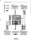
Рис.3 Конструкция уровнемера
Электронный блок может содержать следующие электронные платы:
- материнская плата;
- плата преобразования питания (TRC);
- плата процессора (SPC);
- плата полевой связи (FCC);
- плата обработки аналоговых сигналов (АРС);
- плата интерфейса (TIC) — дополнительно;
- плата температурных входов (ТМС) — дополнительно;
- плата релейных выходов (ROC) — дополнительно.
Модуль FCU осуществляет сбор данных с подключенного к портам полевой шины оборудования, записывает их в буферную память и по запросу передает эти данные на оборудование «верхнего» уровня через порты групповой шины.
К портам полевой шины может подключаться полевое оборудование системы, смонтированное на резервуарах: уровнемеры REX, модули DAU, дисплейные панели RDU 40 и пр. – для этих устройств модуль FCU является Master устройством.
Модуль FCU 2160 имеет шесть портов Х1…Х6 для подключения полевых и групповых шин. Порты могут быть индивидуально сконфигурированы либо в качестве порта групповой шины, либо в качестве порта полевой шины. Для работы по интерфейсу RS232 необходимо вместо платы FCM вставить в порт специальную заглушку, для работы по интерфейсу RS485 – плату FCI.

Рис.4 Внешний вид FCU 
Рис.5 Порты полевой шины
Модем полевой шины (FBM) является преобразователем интерфейса полевой шины системы TRL/2 в стандартный интерфейс RS232 и обратно, информационным протоколом при этом является протокол Modbus. Модем FBM используется для подключения персонального компьютера с программным обеспечением TankMaster к шине TRL/2 напрямую или к модулю FCU
Программное обеспечение TankMaster
Программное обеспечение Saab TankMaster включает в себя следующие основные модули:
- TankServer.
- WinSetup.
- WinOPI.
- Master Protocol Server.
- Slave Protocol Server.
Программа TankServer (ОРС-сервер) является ядром программного обеспечения TankMaster. Именно эта программа в реальном масштабе времени через программу Master Protocol Server осуществляет обмен с устройствами системы, контроль за значениями параметров продукта в резервуарах и, в случае выхода их значений за установленные пределы, формирует сигналы тревоги. Данные об устройствах системы, их имена, данные их конфигурации (тип антенны, количество подключенных датчиков температуры, давления, подтоварной воды и пр.) хранятся в базе данных программы TankServer. В этой базе хранятся также данные о резервуарах (тип, градуировочная таблица, количество и тип устройств на этих резервуарах), а также данные о продукте в резервуарах. Обмен информацией с системами верхнего уровня осуществляется с использованием программы Slave Protocol Server.
Программа WinSetup представляет собой ОРС-клиент и используется для настройки базы данных TankServer в части инсталляции и конфигурации устройств системы TRL/2, а также для настройки связи с системами верхнего уровня.
Программа WinOpi также представляет собой ОРС-клиент и является основной программой программного обеспечения TankMaster, которая обеспечивает настройку системы коммерческого
Шина TRL/2
В системе TRL/2 используется специализированный физический протокол для передачи данных. Принцип передачи данных – полудуплекс с частотной модуляцией (передаче «нуля» соответствует посылка с частотой 90 кГц, передаче «единицы» – посылка с частотой 100 кГц), скорость передачи – 4800 бод. Этот принцип передачи данных был разработан для обеспечения помехозащищенной связи на расстоянии до 4-х км.
Информационным протоколом передачи данных в системе TRL/2 является протокол Modbus RTU.
Полевая шина может подключаться как модулю FCU, так и к рабочей станции TankMaster через модем полевой шины FBM. Каждый уровнемер REX, модуль DAU и модуль FCU должны иметь в системе свой уникальный адрес для обмена информацией по протоколу Modbus. К одной полевой может быть подключено не более 8 уровнемеров и не более модулей DAU.
Кабель, по которому осуществляется обмен информацией между модулем FCU и рабочей станцией TankMaster или контроллером системы управления, в системе TRL/2 называется групповой. К порту групповой шины модуля FCU может быть подключено только одно внешнее устройство (рабочая станция
Лабораторная работа
Тема: Конфигурирование уровнемера SAAB
Цель работы: ознакомиться с возможностями системы STRL-2 и основами настройки
Оборудование, программное обеспечение: радарный уровнемер SAAB
Задание:
- Ознакомиться с документацией на уровнемер SAAB TANK RADAR.
- Произвести настройку и конфигурирование уровнемера
- Сделать выводы по результатам настройки.
- Выполнить дополнительные работы, например: установить программу Win
Setup на ноутбук и попытаться заново произвести настройку; произвести подключение дополнительного датчика температуры
- Вычертить схему соединения уровнемера к среднему и верхнему уровню
- Ответить на контрольные вопросы
Ход работы:
- Произвести запуск Win Setup
- Проверить связь по Modbus. Правая кнопка на Find Devicec.Затем шелчок на Start

Рис. 6
- Нажимаем правую кнопку. Выбираем новую инсталляцию. Выбираем устройство и присваиваем устройству имя.

Рис.7
- Нажимаем «NEXT». Меняем адрес устройства.

Рис.8
- Нажимаем «Verify Communication». Нажимаем «NEXT».

Рис.9
- Подчинённым устройством должен стоять «REX RTG»

Рис.10
В результате производим инсталляцию радара.

Рис.11

Рис.12
Рис.13
- Нажимаем NEXT. Вводим тип антенны

Рис.14
- Проверяем работу радара. Нажимаем «Tanr Skan».

Рис.15
- Проверяем температурные входы. Вводим положение датчиков.

Рис.16
Нажимаем «OK» и «NEXT». Вводим параметры расположения антенны
Рис.17
- Инсталлируем резервуар «LT»

Рис.18
Настраиваем параметры резервуара. Инсталлируем цилиндрический резервуар

Рис.19
Привязываем установленные устройства к резервуару

Рис.20

Рис.21
И нажимаем на указатель добавления

Рис.22
- Устанавливаем источники сигналов и единицы их измерения

Рис.23

Рис.24

Рис.25
- Завершаем настройку. Проверяем изменение параметров при изменении уровня жидкости в резервуаре

Рис.26

Рис.27
Контрольные вопросы
1.Назначение системы SAAB TANK RADAR
2. Состав системы SAAB TANK RADAR
3. Характеристика интерфейса TRL
4. Состав и назначение программных средств
Литература
SAAB TANK RADAR Техническое описание
SAAB TANK RADAR Инструкция по настройке и конфигурированию
SAAB TANK RADAR Инструкция по монтажу
|
Detail Specifications: 1112/1112024-tankradar_pro.pdf file (01 Dec 2022) |
Accompanying Data:
Saab TankRadar PRO Measuring Instruments, Radar PDF Operation & User’s Manual (Updated: Thursday 1st of December 2022 10:27:29 AM)
Rating: 4.6 (rated by 33 users)
Compatible devices: DIGIMET E35, fieldscout TDR 300, BS Series, XPDM, LabSen 803, EX357A94, EV 3-2, CSM.
Recommended Documentation:
Text Version of Operation & User’s Manual
(Ocr-Read Summary of Contents, UPD: 01 December 2022)
-
15, Saab TankRadar ® ProMechanical Installation 2-22 Edition 3. Ref. No: 306010E 12. When the antenna inclina- tion is adjusted to obtain optimum performance, (see pt.8), tighten the finger nut and the lock nut firmly. Secure by folding the tab washer over the lock nut. 11. Rotate the transmitter head so that the cover locking is directed 90 degrees to- wards the groove along the …
-
2, Saab TankRadar ® Pro iii Edition 3. Ref. No: 306010E Contents About this manual……………………………………………….. vii 1 Introduction…………………………………………………… 1-1 The TankRadar Pro System ………………………………………………………………….. 1-1 Measurement Principle ……………………………….…
-
3, Saab TankRadar ® Pro iv Edition 3. Ref. No: 306010E 3 Electrical Installation …………………………………….. 3-1 Identication of Installed Options …………………………………………………………… 3-1 Junction Box ……………………………………………………………………………………….. 3-2 External Co…
-
12, Saab TankRadar ® Pro Mechanical Installation 2-19 Edition 3. Ref. No: 306010E 4. Turn the flange around and mount the antenna feeder on the flange. Mount the washers and nuts. 5. Tighten the Finger Nut and the Lock Nut loosely. 6. Place the antenna on the tank nozzle and tighten the flange screws. Lock Nut Tab Washer Finger Nut Washer Ball Lock Washer Antenna Feed…
-
5, Saab TankRadar ® Pro Mechanical Installation 2-3 Edition 3. Ref. No: 306010E Free Space Requirements Position the gauge in a way that allows the microwaves to propa- gate without disturbance from the tank wall, according to the illustration below. In order to achieve optimum performance you should consider the following recommendations: • Try to avoid obstacles in the radar …
-
13, Saab TankRadar PRO Saab TankRadar ® ProMechanical Installation 2-20 Edition 3. Ref. No: 306010E 7. Rotate the antenna so that the groove on the Antenna Feeder is directed 90° to the tank wall. Tighten the Finger Nut and the Lock Nut. 8. Mount the Pro adapter on top of the antenna feeder. Tighten the Adapter Nut loosely so the transmitter head can be properly aligned. Normally the a…
-
8, Saab TankRadar ® ProMechanical Installation 2-4 Edition 3. Ref. No: 306010E Beam Width Beam angle annetnAhtdiWmaeBrewoPflaH «3enoC/doR°52 /»4enoC «4laeSssecorP °12 /»6enoC «6laeSssecorP °81 «8enoC°51 alobaraP°01 annetnA tnereffidtaaeradetaidarforetemaiD )tf(/m,egnalfmorfsecnatsid m5 )tf61( m01 )tf33( m51 )tf94( m02 )tf66( «3enoC/doR)2.7(/2.2)41…
-
11, Saab TankRadar PRO Saab TankRadar ® ProMechanical Installation 2-18 Edition 3. Ref. No: 306010E Mounting the Antenna 2. Tighten the screws. 1. Fit the Parabolic Reflector to the Antenna Feeder and mount the five M5 screws. 3. Put the two O-rings in the grooves on the upper surface of the Flange Ball. Note! Use the screws delivered by Saab Tank Control. O-rings ´ 2 Flange Ball Parabolic Reflector Antenna Feeder M…
-
4, Saab TankRadar PRO Saab TankRadar ® Pro v Edition 3. Ref. No: 306010E 4 Pro Setup Software ……………………………………….. 4-1 System Requirements ………………………………………………………………………….. 4-2 Installing the Pro setup software ………………………………………………………….. 4-2 Starting the Pro Setup…
Recommended Instructions:
WPC54GX, COLORKATALOG D-2005, SSE-120, LE32B550A5W, A55F-M2, SE6551B


-
Rhein Tech Laboratories Client: Ohmart/VEGA 360 Herndon Parkway Model: VEGAPULS 616263 Suite 1400 …
VEGAPULS 62 73
-
Level and interface measurement in liquidsApplication• Rod, rope or coax probe• Process connection: Starting 3/4″ thread or flange• Process temperature: –50 to +200 °C (–58 to +392 °F)• Process pressure: –1 to +40 bar (–14.5 to +580 psi)• Maximum measuring range: Rod 10 m (33 ft); rope 45 m (148 ft); coax 6 m (20 ft)• Accuracy: ±2 mm (±0. …
Levelflex FMP51 88
-
Raytheon Model R20 Raster Scan Radar System OPERATION REFERENCE GUIDE 1 . To turn set on press CS’fEiY.D~F . To transmit press i XMIT/OFF .. To turn off press l)TBY.1Q£.( and f~_[T OFF together. 2. To change: : Ranges; Press~·GE-and A. or ‘Y key. : Gain Level; Press GAIN and A. or ‘Y key. : Sea Clutter; Pres; SEA-CL and A or ‘Y key. : Rain Clutter; PressRA1&quo …
R20 22
-
Baumer Electric AG, Hummelstrasse 17, 8501 Frauenfeld, Switzer-land 1/36 R600V.DAH5 Multi-Object Operating Manual (EN) Off-Highway Multi-object Radar Sensor Last Update: 01 Jan 2021 …
R600V.DAE0 36