- Manuals
- Brands
- Sailor Manuals
- Marine Radio
- RT5022 VHF DSC
- Operation manual
-
Contents
-
Table of Contents
-
Troubleshooting
-
Bookmarks
Quick Links
OPERATION MANUAL
SAILOR RT5022 VHF DSC
SAILOR RT5020 VHF DSC Duplex
Related Manuals for Sailor RT5022 VHF DSC
Summary of Contents for Sailor RT5022 VHF DSC
-
Page 1
OPERATION MANUAL SAILOR RT5022 VHF DSC SAILOR RT5020 VHF DSC Duplex… -
Page 3: Introduction
— a position which has been maintained by means of constant and extensive product development. We have a worldwide network of distributors with general agencies in more than 80 countries. All our distributors are specially trained to service all your SAILOR ®…
-
Page 4: Training Information
Training Information The Thrane & Thrane RT5022/RT5020 VHF radio is designed for “occupational use only” and is also classified as such. It must only be used in the course of employment by individuals aware of both the hazards as well as the way to minimize those hazards. The radio is thus NOT intended for use in an uncontrolled environment by general public.
-
Page 5: Quick Dsc Distress Call
Quick DSC distress call (only for emergency use) 1. If necessary, switch on by pressing the ON/OFF button 2. Lift up the lid covering the orange key and press for 5 seconds. 3. The Alarm indicator light will flash and will be accompanied by a sound. Distress message is sent at the continuous tone.
-
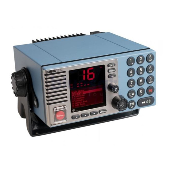
Page 6: Your Vhf At A Glance (Rt5020/Rt5022)
Your VHF at a glance (RT5020/RT5022) Alarm Call 0191 — 05 1. Loudspeaker 7. Dimming button 2. Volume level indicator 8. Menu button 3. Squelch level indicator 9. Mute alerts 4. Indicator lamps. Condition when lit: 10. Keyboard. 1W: 1 watt transmission mode. 11.
-
Page 7: Table Of Contents
Contents Introduction ……………………..i About this manual ……………………. i Abbreviations used in this manual ………………i Training Information …………………… ii Quick DSC distress call ………………….iii Mayday procedure ……………………iii Your VHF at a glance (RT5020/RT5022) …………….iv Radio communication in brief ………………3 Powering VHF ………………….
-
Page 8
DSC operations in detail ………………..14 MMSI Number ………………….14 Group MMSI number ………………..15 Differentiating incoming calls by ringing tones …………15 Working channel ………………….. 16 Contact list …………………… 16 Settings for DSC ………………….. 18 Implicit behaviour for operations with DSC ………….. 19 Radio configuration and settings ……………. -
Page 9: Radio Communication In Brief
1 Radio communication in brief Powering VHF The VHF is turned on by a single press on the ON/OFF/Volume button. The VHF is turned off by pressing the ON/OFF/Volume button for 3 seconds. Always indicated by a count down window in the information display, except if the radio is powered down in distress mode.
-
Page 10: Making A Radiotelephone Call
6. Switch to the new channel – for example, channel 71 – and begin your conversation. Press PTT only when you are talking. If you are on a simplex channel (in other words, a channel that can carry only one transmission at a time), always say “Over”…
-
Page 11: Channel Selection
Channel selection The system is defaulting to channel 16 after a normal power-on. Channels can be selected using the (increasing to next valid VHF channel) or (decreasing channel). Channels can also be entered using the numeric keypad. The active working channel is always shown in the upper display. Dual watch Dual watch is a mode where the priority channel (16) is scanned periodically for a signal while listening on a working channel.
-
Page 12: Dimming
When releasing the replay button the replay function will take over the audio system and start to replay the last XX seconds of data received on any channel. The time when the traffic was received and the channel on which it was received is displayed during replay. Volume control can be used on the replay data to adjust sound pressure in audio devices.
-
Page 13: Basic Dsc Operations
2 Basic DSC operations When switched on, your VHF automatically monitors channel 70 for incoming DSC calls. Menu operation To operate DSC functionality the menu system is used. The main menu can be activated by pressing . From the main menu all parts of the menu tree can be reached (see chapter: Menu tree).
-
Page 14: Transmitting Dsc Calls
If you are busy you can choose to handle the call a little later (e.g. by pressing which will stop the alarm sound. When you are ready to accept the call, lift the handset or press . Your choices handling the particular call will now appear. Follow the instructions. If an individual call is received it will not be acknowledged before you accept the call.
-
Page 15: Create Emergency Calls
Create emergency calls In the category of emergency calls (1.4) you will find the Emergency following menu: 1 Compose Distress 2 Compose Urgency 3 Compose Safety Transmitting any of these calls should be done with 4 Compose Relays caution. Please make yourself familiar to the common 5 Compose Distress Ack procedures for using these calls.
-
Page 16: Your Vhf In Detail
3 Your VHF in detail Abnormal power-down If for any reason the main power disappears for a period less than 10 minutes, the VHF will be able to turn itself on when power is resumed (without pressing ON/OFF). If the VHF was abnormally powered down for less than 1 minute, the VHF will start up with the same settings as before the power failure took place (communication channel, volume, squelch settings, etc.).
-
Page 17: Setting Channel Mode
Setting channel mode The VHF is delivered from factory with both Int. & US channels enabled for selection from the operation menu. Provision of other country regions (channel tables) for selection requires the intervention by an authorized Thrane & Thrane representative in order to enable such. The operator selection of preferred country region (channel table) is done from menu 4.4.1 (channel mode) and the selected country region is indicated in the front panel display (note: this does not apply to the CA channel table and any custom defined channel tables).
-
Page 18: Atis (Inland Waterways Only)
ATIS (inland waterways only) ATIS is mandatory to use in inland waterways on e.g. the Rhine. ATIS is a digital data stream containing ships call sign coded into a DSC-like message, sent over the voice channel each time the PTT button is released. If PTT is continuously pressed ATIS is automatically sent each 5 minutes.
-
Page 19: Channel Scanning
Channel scanning Scanning is an extension to the dual watch functionality, by which it is possible to watch multiple channels. It is possible to scan: • All channels in a sequence • A number of selected channels in a sequence organized into individual 3 scan tables — Scan table A, B and C.
-
Page 20: Dsc Operations In Detail
4 DSC operations in detail MMSI Number To operate VHF with DSC the equipment needs to be configured with vessel’s MMSI number. If not configured before installation, the VHF will prompt for programming of the 9- digit MMSI number, at start-up. The vessel’s MMSI number is programmable from the DSC menu (4.5).
-
Page 21: Group Mmsi Number
Group MMSI number If the VHF radio is configured as member of a group(s) it will receive group calls addressed to that group. The VHF can be configured to be part of more (up to 10) groups. The group MMSI numbers can be programmed from menu 4.5.2.
-
Page 22: Working Channel
Working channel A working channel will always be suggested by the system if a ship station or group is called for a routine call. The working channel is suggested by using the following procedure: 1. Select a random channel from the list of simplex channels 2.
-
Page 23
• If the MMSI number is a group number, the group call flow is entered from the window where a channel is selected. • If a ship station number MMSI is available, the station call flow is entered from the window where a channel is selected. -
Page 24: Settings For Dsc
4.5.4 Editing the contact list Any contacts from the list can be edited using a similar principle as described above using menu item 2.4. 4.5.5 Deleting a Contact Entry Any contact can be deleted from the contact list. If menu 2.5 is selected the contact can be searched for in the list.
-
Page 25: Implicit Behaviour For Operations With Dsc
4.6.3 Automatic channel shift The VHF can be set to automatically changing the working channel on receipt of the following call types: • Individual radiotelephony acknowledgement with a valid channel information • Radiotelephony group calls with valid channel information • Radiotelephony all ship safety calls with valid channel information The set-up is done via menu 4.5.5.
-
Page 26
4.7.3 Verification of a DSC call before transmission The final step in each DSC call sequence is the verification window, in which it is possible to verify the call that is about to be transmitted. By default only information that may be influenced in the call setup will be displayed. -
Page 27: Radio Configuration And Settings
Radio configuration and settings This section describes the configuration and settings possible to control from the operator front panel and is not described elsewhere in this manual. If configuration of the VHF beyond these possibilities is required, contact the local T & T representative for assistence.
-
Page 28: Voice Scrambler
When the pin code has been entered and the scrambling option enabled, the scrambling feature remains permanently available for selection. For details on how to obtain the scrambling feature for your SAILOR RT5022/RT5020 VHF, contact your local Thrane & Thrane representative.
-
Page 29: Automatic Conditions
The scrambled call can be set up immediately between two RT5022/RT5020, if both are having the scrambler application enabled (scramble pin code is set). The voice scrambler can be initiated by any of the two parties from the main menu (6). Selecting the scrambler will initiate a sequence similar to a DSC station call.
-
Page 30: Software Releases
4.11 Software releases 4.11.1 Radio software release The RT5022/RT5020 running software version can be read out from menu 4.6.1.1. The version information displayed is partitioned into three sections: • Main Release X.YY.zz. Bundled sample software release tag. Will follow host processor software tag.
-
Page 31: Errors And Warnings
Errors and warnings Errors and warnings are shown in the display accompanied by the sounds shown in the figure below: TONE SIGNAL 1 sec. 8 sec. ERRORS WARNING & INFO 39718 In case of an error or warning message it is always possible to mute the alarm sound. Press in order to finish the current radiotelephony call.
-
Page 32
5.2.1.1 Ship´s power Ship´s power may occasionally be interrupted for a short time, e.g. if switching between land power or generator power. The VHF equipment will turn off immediately when power is failing. If power does not resume within 10 minutes the VHF cannot be expected to start up automatically. -
Page 33
5.2.3 Symptom: Position requested Possible cause/remedy: In case of the VHF, despite being connected to a GPS/position source, prompts for entering of the position and time information the automated update has most likely been lost either due to missing data on the line, broken cabling or the GPS/ position source has failed. -
Page 34
5.2.6 Missing MMSI Symptom: DSC operation is not working Possible cause/remedy: When powering up the VHF for the first time after leaving factory no MMSI identity resides in the VHF. For the DSC operation to function the VHF must be programmed with MMSI identity (refer to menu 4.5.1). -
Page 35: Menu Tree
6 Menu tree This section lists the full menu tree of the VHF. The table describes the un-regretted forward flow that is initiated after selection of certain menu items. Generally, pushing in the menu tree or flow sequence will return to the previous window.
-
Page 36
Settings Channels 4.4.1 Channel Mode 4.4.2 Channel Info 4.4.3 ATIS Call sign 4.5.1 MMSI Num ber 4.5.2 Group MMSI Medical Transports 4.5.3 Special Calls Ships and Aircrafts Safety Test 4.5.4 Auto Acknow ledgem ent Routine Polling Safety Position RT acknow ledgement 4.5.5 Auto Channel Sw itch Group Calls… -
Page 37: Optional Functional Devices
7 Optional functional devices The maximum system configuration possible with your VHF installation with VHF is shown in the first part of the installation section. The present chapter will describe the functionality and behaviour of the following optional functional devices: •…
-
Page 38
7.1.2 Operation The optional handset is intended for VHF radiotelephony only. There will be no DSC functionality supported except for: • The functionality or lifting of the CU handset follows the default handset on the main radio (see Section DSC receive), when receiving a DSC call. •… -
Page 39
7.1.6 Squelch The squelch level can be adjusted by using the buttons. Pressing the buttons will contribute to the global squelch setting on the radio. Squelch indicators on the handset CU and on the main unit will always follow each other regardless of the control input used for adjustment. -
Page 40
alternating … on errors..on alerts. This indication will remain until the DSC call has been handled from the main unit. Though normal radiotelephony calls can be acknowledged from the semi-intelligent handset making the HS hooked to HS un-hooked transition. 7.1.9 Muting alarms If a DSC call is received (distress or routine) the alarm sound is heard as a mixing of the… -
Page 41: Alarm Panel
7.1.13 Multiple handsets in the system If multiple handsets are connected in the system the following priority is given (to PTT – microphone control) if multiple handsets are lifted: • The default handset is always given priority if lifted. • Any optional handset lifted first takes priority over another optional handset.
-
Page 42: Printer
Printer An optional printer may be installed with the VHF for printing of DSC messages and logs. Printer installatioin and hook up to the VHF equipment should be performed by authorised and properly trained service personnel only. Printing 1.5.4 Individual messages from the DSC call logs may be 1 Print Distress Log printed.
-
Page 43: Maritime Channels
8 Maritime Channels International channels Channels SIMPLEX DUPLEX Channels SIMPLEX DUPLEX Intership Port Port Public Intership Port Port Public 156,050 160,650 156,025 160,625 156,100 160,700 156,075 160,675 156,150 160,750 156,125 160,725 156,200 160,800 156,175 160,775 156,250 160,850 156,225 160,825 156,300 156,300 156,275 160,875 156,350 160,950 156,325 160,925…
-
Page 44: Us Channels
US channels Channels SIMPLEX DUPLEX Channels SIMPLEX DUPLEX Channels 156,050 156,050 162,550 156,075 156,075 162,400 156,150 156,150 162,475 156,175 156,175 162,425 156,250 156,250 156,225 156,225 162,450 156,300 156,300 156,275 156,275 162,500 156,350 156,350 156,325 156,325 162,525 156,400 156,400 156,375 156,375 161,650 156,450 156,450 156,425 156,425…
-
Page 45: Bi Channels
BI channels Channels SIMPLEX DUPLEX Channels SIMPLEX DUPLEX Intership Port Port Public Intership Port Port Public 156,050 160,650 156,025 160,625 156,100 160,700 156,075 160,675 156,150 160,750 156,125 160,725 156,200 160,800 156,175 160,775 156,250 160,850 156,225 160,825 156,300 156,300 156,275 160,875 156,350 160,950 156,325 160,925 156,400 156,400…
-
Page 46: Ca Channels
CA channels Channels SIMPLEX DUPLEX Channels SIMPLEX DUPLEX Channels 156,050 160,650 156,025 160,625 162,550 156,100 160,700 162,400 156,150 160,750 162,475 156,250 156,250 156,225 160,825 156,300 156,300 156,275 156,275 156,350 156,350 156,325 156,325 156,400 156,400 156,375 156,375 156,450 156,450 156,425 156,425 156,500 156,500 156,475 156,475 156,550 156,550…
-
Page 47: Installation
9 Installation Mounting possibilities VHF with mounting bracket 39835 Relief bracket for handset cable 99-126905 0833…
-
Page 48
Mounting option Drilling plan 4xø5.5 39837 Tilting +/- 20° Weight (RT5022): 4.1 kg Mounting bracket 1.0 kg Weight (RT5020): 4.9 kg Mounting bracket 1.0 kg 39836 VHF with flush mounting bracket Bracket (Option) min. 100.00 Space for Cable entry 39938 Drilling plan Weight: 4 pcs. -
Page 49
4 pcs M3x30 6 pcs M4x8 4 pcs M4x30 39966 Handset for transceiver Drilling plan * 120 Space for handset access This Handset has a hook-on/off function, which is activated by a small magnet embedded in the ceadle. The cradle must be installed as illustrated in order to ensure the hook-on/off functionality of the Handset. -
Page 50
Semi-functional control unit Drilling plan Space for installing and detaching control unit 2xø5 2xø4.5 This Handset has a hook-on/off function, which is activated by a small magnet imbedded in the cradle. The cradle must be installed as illustrated in order to ensure the Length of spiral cord hook-on/off functionality of the at rest : 380 mm… -
Page 51
Connection box Drilling plan 4 pcs. ø6 258.4 9.75 Mounting * 50 * 50 * Free space for mounting, ** Free space for cable entry. 39656 Weight Connection box 1.7 kg 0605… -
Page 52
Extension box Drilling plan 4 pcs. ø6 141.4 Mounting * 50 * 50 Weight Extension box 0.7 kg * Free space for mounting, ** Free space for cable entry. 39657 0605… -
Page 53: Compass Safe Distance
LAN box Drilling plan 4xø4.5 4xø3.5 74.5 Mounting * 50 Weight LAN box 0.3 kg * 50 * Free space for mounting, ** Free space for cable entry. 39658 Compass safe distance Safe distance in accordance with Annex A of ISO 694:2000. Safe distance between the nearest point of the item and the centre of the compass at which it will produce a diviation of 0.3°…
-
Page 54: Interface Connections
Interface connections VHF (rear view) Power 15-pin connector sub D male Option FUSE 12-24V DC 15-pin sub D female Sparc II Bus 9 pin sub D female Handset Main Antenna DSC Antenna 39815B 0645…
-
Page 55
Connection box board 639121 IF CU IS CONNECTED TO EB/CU EB/CU EB/CU TERMINALS THEN REMOVE J1 & J2 FOR X4 EXT / AND J3 & J4 FOR X5 RT50XX RT50XX EXT / CU LS CU LS OPTIONS OPTIONS SPARC II VDR+ +12.5V VDR-… -
Page 56
9.3.1 System block diagram with connection box and 2 x extension box 0645… -
Page 57
Cable connection diagram IF CU IS CONNECTED TO EB/CU TERMINALS THEN REMOVE J1 & J2 FOR X4 OPTIONS CONNECTIONS SPARC II BUS CONNECTIONS AND J3 & J4 FOR X5 RT50XX RT50XX OPTIONS OPTIONS SPARC II EB/CU EB/CU EXT / EXT / VDR+ +12.5V CU LS… -
Page 58
Interfaces Signal Cable Connection Connection Signal description Ships cable Options connector designation p/n 539603 8 twisted pairs In from VHF External conn. overall screen 15-pin D-sub male Mixed Rx/Tx audio output for VDR+ Brown pin 1 X1-1 X2-1 pair no. 1 recording. -
Page 59
9.3.2 System block diagram with extension box 0645… -
Page 60
Cable connection diagram X6 : J1 & J2 MOUNTED = EXT LS J1 & J2 NOT MOUNTED = CU LS CU LS+ EXT/CU EXT LS+ CU LS- EXT LS- EXT/CU +12.5V DATA+ DATA- TX AF+ TX AF- +12.5V RX AF+ RX AF- +12.5V Line out… -
Page 61: Power Supply
Power supply The VHF should be powered from a separately fused DC-supply of 10.8 — 32VDC and rated at minimum 120W continuous power for installations with RT5022 (Simplex/semi-duplex),and 150W for installations with the RT5020 (Duplex) Antenna installation and precautions 9.5.1 Antennas The VHF equipment requires two antennas installed one for the DSC receiver and the other (Primary) for the VHF RX/TX communication.
-
Page 62
9.5.3 DSC antenna The positioning of the DSC antennas is less critical in terms of the imposed VSWR and due to the nature of the DSC-signalling. It should be noted however, that the DSC receiver of a VHF is likely to be temporarily blocked in reception due to high signal blocking, if the associated DSC antenna is installed in close vicinity of a RX/TX antenna at the same horizontal level while transmission takes place from this RX/TX antenna. -
Page 63: Technical Specifications
10 Technical specifications 10.1 General information Channel Tables 4 pre-programmed channel tables covering the following regions: • International waters — according to radio regulations • US waters – according to radio regulations • Inland waters (with ATIS) – according to radio regulations •…
-
Page 64: Specific Data For Transceiver Unit Rt5020
Supply voltage 12V to 24V DC nominal Supply range 10.8V to 31.2V DC Power requirements-Tx Min. 120W continous Power requirements-Rx(w.2CUs) Max 25W Power requirements-Rx(stand alone) Max 15W Transceiver dimensions H*W*D 100*200*210 mm Transceiver weight 4.1 Kg Receiver Sensitivity for 20 dB SINAD CCITT weighted -119 dBm typical AF rated Power…
-
Page 65
Receiver Sensitivity for 20 dB SINAD CCITT weighted -119 dBm typical Duplex spurious response att. More than 74 dB Duplex desentization below 3 dB AF rated Power Internal L.S. 5 Watt in 8 ohm Output for External L.S. 5 Watt in 8 ohm Distortion below 5 % S/N ratio… -
Page 68
B5022GB0 Issue: L /09 02 Thrane & Thrane A/S info@thrane.com www.thrane.com • •…
Table of Contents for Sailor RT5022:
-
8 Basic If you are busy you can chose to handle the call a little later (e.g. by pushing ), which will stop the alarm sound. Once you are ready to accept the call, lift the handset or press . Your choices handling the particular call will now appear. Follow the instructions. If an individual call is received it will not be acknowledged before you accept the call. 2.3 Transmitting DSC Calls All DSC calls are initiate
-
30 System 0505 7.1.11 Multiple Handsets in the System If multiple handsets are connected in the system the following priority is given (to PTT – microphone control) if multiple handsets are lifted: • Default handset is always given priority if lifted. • Any optional handset lifted first takes priority over another optional handset. A warning “OC” is written in the display near any handset (VHF unit or CU) that has lower priority, as soon the prioritized hand
-
39 Installation 0505 Extension Box 4 pcs. ø6 Drilling plan 39657 ** Free space for cable entry. * Free space for mounting, Mounting 141.4 160.4 49 * 50 ** min. 100 * 50 * 50 122 9.7 14.85 120 Weight Extension Box ??0.7 kg
-
4 Basic 0505 1.4 Making a Radiotelephone Call A radiotelephone call is preferably to be commenced using DSC. Alternatively the following public calling procedure shall be used: 1. Select channel 16 (by pressing ) or other agreed channel. 2. Lift the handset. 3. Press the PTT key and make your call. First, say the name of the station you are calling three times. Then say
-
36 Installation 0505 Handset for Transceiver 39655 Drilling plan 75 62 226 * 120 Space for handset access min. 200 Space for cable and handset cable 78 16 70 41 54 Weight Handset for Transceiver 0.4 kg
-
41 Installation 0505 9.2 Interface connections VHF (rear view) Option Sparc II Bus Handset 12-24V DC Main Antenna DSC Antenna 39815 FUSE
-
18 Detail 4.6.2 Automatic Acknowledgement The VHF can be set up to automatic acknowledge the following calls: • Safety Position Requests — Default disabled after power-up • Safety Test Requests — Default enabled after power-up • Routine Polling Requests — Default enabled after power-up After power-up the behavior can be changed from menu 4.5.4. The automatic acknowledgement (if enabled) will take place without informing the operator. The calls are stored in the receive/transmit log. The operator might experience a short
-
15 Detail If an individual call acknowledgement is received, an alarm tone is activated that is equal to the alarm tone used for receiving a call request of the same type. Calls that are not received as distress calls or calls with category distress or urgency will always engage the prescribed alarm sound. For any other DSC calls the call sound on reception can be enabled/disabled from a setup menu (4.3.2). If you receive a call with an alarm
-
42 Installation 0505 Connection box board 639121 39816 X7 X8 X9 X4 X3 X5 X6 X1 X2 J1 J2 J3 J4 RX AF+ 2 Line out+ 1 +12.5V RT502X RT502X TX AF- GND DATA+ +12.5V X7 LAN DATA- TX AF+ +12.5V RX AF- CONNECTIONS 2 OPTIONS EXT LS2 CONNECTIONS GND EXT LS2 Line out- VDR- 1 AUX2 CALL GND NMEA+ AUX1 AUX1 VDR+ AUX2 EXT LS1 EXT LS1 ALARM CALL ALARM NMEA- SPARC II BUS 1 6 5 7 4 3 2 9 8 10 15 14 11 12 13 1 6 2 3 4 7 5 14 10 8 9 13 12 15 X5 X9 CU 2 X8 15 11 11 OPTIONS 12 13 9 CU 1 8 EXT X6 10 14 5 7 4 3 2 6 1 X2 15 13 9 8 10 14 5 7 4 1 6 2 3 4 7 5 14 10 8 9 13 X4 X3 15 3 2 6 1 X1
Questions, Opinions and Exploitation Impressions:
You can ask a question, express your opinion or share our experience of Sailor RT5022 device using right now.
|
Detail Specifications: 1169/1169195-rt5022_vhf_dsc.pdf file (28 Oct 2022) |
Accompanying Data:
Sailor RT5022 VHF DSC Marine Radio PDF Operation Manual (Updated: Friday 28th of October 2022 11:13:48 AM)
Rating: 4.3 (rated by 73 users)
Compatible devices: RT4722, A1 VHF-DSC, UAIS1900, VHF 300 — Marine Radio, UBCD436-PT, C4900, RT-550, TRA2.G2.EX.
Recommended Documentation:
Text Version of Operation Manual
(Ocr-Read Summary of Contents, UPD: 28 October 2022)
-
22, 16 Detail 4.4 Working channel A working channel will always be suggested by the system if a ship station or group is called for a routine call. The working channel is suggested by using the following procedure: 1. Select a random channel from the list of simplex channels 2. Scan channel for traffic (open squelch) 3. If the channel is free suggest the channel. 4. If…
-
39, Sailor RT5022 VHF DSC 33 System 7.1.6 Squelch The squelch level can be adjusted by using the and buttons. Pressing the buttons will contribute to the global squelch setting on the radio. Squelch indicators on the handset CU and on the main unit will always follow each other regardless of the control input used for adjustment. NOTE: If a channel is reached where the squelch setting was pro…
-
6, Int US BI Tx Call DW 1W Vol SQ Alarm 0191 — 05 Your VHF at a glance (RT5020/RT5022) 1. Loudspeaker 2. Volume level indicator 3. Squelch level indicator 4. Indicator lamps. Condition when lit: 1W: 1 watt transmission mode. Alarm: Alarm call received. Call: DSC call for you received. DW: Dual watch mode 5. Telephone display 6. Indicators. Condition when lit: Tx: Transmi…
-
27, 21 Detail 4.8 Radio configuration and settings This section describes the configuration and settings possible to control from the operator front panel and is not described elsewhere in this manual. If configuration of the VHF beyond these possibilities is required, contact the local T & T representative for assistence. 4.8.1 Idle display Whenever the radio is le…
-
19, 13 Detail 3.9 Channel scanning Scanning is an extension to the dual watch functionality, by which it is possible to watch multiple channels. It is possible to scan: • All channels in a sequence • A number of selected channels in a sequence organized into individual 3 scan tables — Scan table A, B and C. The scan type can be selected from the Scanning menu (3). The DW indicat…
-
15, 9 Basic 2.8 Create emergency calls In the category of emergency calls (1.4) you will find the following menu: Emergency 1.4 2 Compose Urgency 5 Compose Distress Ack 3 Compose Safety 4 Compose Relays 1 Compose Distress Transmitting any of these calls should be done with caution. Please make yourself familiar to the common procedures for using these calls. Selectin…
-
28, 22 Detail • When turning off the VHF using the button, the VHF — for regulatory reasons- will power up in the default language (English) mode when again turned on, irrespective of which language selection had been made prior to turning off the VHF. • The following sequence of key strokes will select the default language (except when the VHF is in distress state – wait…
-
12, Sailor RT5022 VHF DSC 6 Basic When releasing the replay button the replay function will take over the audio system and start to replay the last XX seconds of data received on any channel. The time when the traffic was received and the channel on which it was received is displayed during replay. Volume control can be used on the replay data to adjust sound pressure in audio devices. During replay “— —” i…
-
16, 10 Detail 3 Your VHF in detail 3.1 Abnormal power-down If for any reason the main power disappears for a period less than 10 minutes, the VHF will be able to turn itself on when power is resumed (without pressing ON/OFF). If the VHF was abnormally powered down for less than 1 minute, the VHF will start up with the same settings as before the power failure too…
Recommended Instructions:
EL-9650, TH 450, PK950N, LX505, PHANTOM 4 PRO


-
Owner’s ManualNothing Comes Close to a Cobra® EnglishClass-D Fixed Mount VHF RadioMR F57WMR F57BPrinted in China Part No. 480-1015-P Version C®®This radio is a VHF transceiver for xed mounting on your boat. It gives you 2-way vessel-to-vessel and vessel-to-shore station communications, primarily for safety and secondarily for navigation and operational …
MR F57W 23
-
P.O. Box 100 • Hildebran, NC 28637 USA • 828-397-4200 • 828-397-4415 FAXhttp://www.elkproducts.com • email: [email protected]* Note:Battery (ELK-1250) &Transformer (ELK-TRG1640)Included with ELK-982KSold Separately for ELK-982-Optional hookupfor TransmissionShunt (if available)Battery12 Volt* See NoteTransceiver12 Volts D.C.Power InputBell / AlarmInput …
982 2
-
Notes on operation of the ICOM IC M802: 1. It has been noted that the ICOM IC M802 does not like to send DSC messages in low power. For some reason the Antenna tuner cannot tune and results in High reflected RF waves (SWR). This results in improper transmission of the digital calling message. No similar problem has been noted when the radio is set to medium or high power. 2. Since th …
IC-M802 20
Additional Information:
Operating Impressions, Questions and Answers:
SAILOR RT5022 VHF DSC
Year: 2005
Language: english
Author: Thrane & Thrane
Genre: Manual
Publisher: Thrane & Thrane
Format: PDF
Quality: OCR without errors
Pages count: 62
Description: SAILOR marine equipment is specially designed for the extremely rugged conditions on board a ship, based on more than 50 years of experience with all kinds of vessels , from small pleasure crafts, over fishing vessels working under all climatic conditions, to the biggest ships.
SAILOR ®
is one of Europe’s leading manufacturers of maritime radio communication equipment — a position which has been maintained by means of constant and extensive product development. We have a worldwide network of distributors with general agencies in more than 80 countries. All our distributors are specially trained to service all your SAILOR ® products.
About this manual
This manual is for the daily user of the system. Additionally, it includes a section on the installation procedures, and — on page iii — standard distress procedures. We highly recommend you to read the manual before you start using the equipment.
Notice: There may be some minor differences in the graphic layout of the product in the manual compared to the actual physical unit.
Contents
Screenshots
The Thrane & Thrane RT5022/RT5020 VHF radio is designed for «occupational use only»
and is also classified as such.
It must only be used in the course of employment by individuals aware of both the hazards
as well as the way to minimize those hazards.
The radio is thus NOT intended for use in an uncontrolled environment by general public.
The RT5022/RT5020 has been tested and complies with the FCC RF exposure limits for
«Occupational Use Only». The radio also complies with the following guidelines and
standards regarding RF energy and electromagnetic energy levels including the
recommended levels for human exposure:
•
FCC OET Bulletin 65 Supplement C, evaluating compliance with FCC guidelines for
human exposure to radio frequency electromagnetic fields
•
American National Standards Institute (C95.1) IEEE standard for safety levels with
respect to human exposure to radio frequency electromagnetic fields, 3 kHz to 300 GHz
•
American National Standards Institute (C95.3) IEEE recommended practice for the
measurement of potentially hazardous electromagnetic fields – RF and microwaves
Below the RF exposure hazards and instructions in safe operation of the radio within the
FCC RF exposure limits established for it are described.
Warning:
Your Thrane & Thrane radio set generates electromagnetic RF (radio frequency) energy
when it is transmitting. To ensure that you and those around you are not exposed to
excessive amounts of that energy (beyond FCC allowable limits for occupational use) and
thus to avoid health hazards from excessive exposure to RF energy, FCC OET bulletin 65
establishes an Maximum Permissible Exposure (MPE) radius of 3″ (0.9m) for the maximum
power of your radio (25W selected) with an half wave omni-directional antenna having a
maximum gain of 3 dB (5.2dBi). This means all persons must be at least 3″ (0.9m) away from
the antenna when the radio is transmitting.
Installation:
1. An omni-directional antenna with a maximum power gain of 5.2 dBi must be mounted at
least 9.6″ (2.9m) above the highest deck where people may be staying during radio
transmissions. The distance is to be measured vertically from the lowest point of the
antenna. This provides the minimum separation distance which is in compliance with RF
exposure requirements and is based on the MPE radius of 3″ (0,9m) plus the 6.6″ (2m)
height of an adult.
2. On vessels that cannot fulfil requirements in item 1, the antenna must be mounted so
that its lowest point is at least 3″ (0.9m) vertically above the heads of people on deck and
all persons must be outside the 3″ (0.9m) MPE radius during radio transmission.
•
Always mount the antenna at least 3″ (0.9m) from possible human access
•
Never touch the antenna when transmitting
•
Use only authorized T&T accessories
3. If antenna has to be placed in public areas or near people with no awareness of the radio
transmission, the antenna must be placed at a distance not less than 6″ (1.8m) from
possible human access.
Failure to observe any of these warnings may cause you or other people to exceed FCC RF
exposure limits or create other dangerous conditions.
ii
0611