- Manuals
- Brands
- imagistics Manuals
- All in One Printer
- im2330
Manuals and User Guides for imagistics im2330. We have 1 imagistics im2330 manual available for free PDF download: Operator’s Manual
-
Драйверы
2
-
Инструкции по эксплуатации
1

Oce im2330 инструкция по эксплуатации
(194 страницы)
- Языки:Английский
-
Тип:
PDF -
Размер:
6.86 MB
Просмотр
На NoDevice можно скачать инструкцию по эксплуатации для Oce im2330. Руководство пользователя необходимо для ознакомления с правилами установки и эксплуатации Oce im2330. Инструкции по использованию помогут правильно настроить Oce im2330, исправить ошибки и выявить неполадки.
ТЕПЛОЭНЕРГОРЕГУЛЯТОР
ИМ2300 ТЭР
Паспорт, техническое описание и инструкция по эксплуатации
НПП «Интромаг»
Пермь, 2001
ПАСПОРТ
![]() Теплоэнергорегулятор
Теплоэнергорегулятор
ИМ2300 ТЭР
Дата выпуска «____» ________ 200_ г. Зав. № _____________
Изготовитель: НПП «Интромаг», 614600, Пермь, ГСП, ул. Данщина, 19
т.(342-2) 37-17-80, факс (342-2) 37-17-49
1. Технические характеристики
Режимы работы: — регулирование и регистрация температур, управление усилителями мощности, обмен данными с ПЭВМ (режим регулирования),
— определение и запись кодов ТМ датчиков, ввод параметров (режим установок)
индикация ошибки (режим ошибки)
Доступ к режиму установок — по паролю.
Интерфейс связи с ПЭВМ — RS 485, интерфейс связи с ТМ датчиками – MicroLAN.
Количество одновременно выполняемых пользовательских задач — до 2-х.
В каждой задаче поддерживается: ТМ термометров типа DS1820 — до 15, сигнальных ТМ ключей типа DS2405 — до 2, усилителей мощности ИМ2340-УМ – 1.
Мощность исполнительных устройств (на 1 задачу) — до 0.4 кВт.
Диапазон измеряемых температур — -55-+125 С.
Абсолютная погрешность измерения, не более — 0.5С.
Емкость памяти данных — 32 Кбайт, срок хранения данных — неограничен.
Продолжительность работы внутренних часов после отключения сетевого питания — не менее 5-ти суток.
Автоматическая диагностика сбойных и аварийных ситуаций.
Питание — сеть 220В, 50Гц, 4Вт.
Средняя наработка на отказ — 30000 часов, средний срок службы — 10 лет.
Исполнение IP 30, диапазон рабочих температур — 0 — 45С.
Габариты 165х115х45 мм, масса, не более — 450 г.
2. Комплект поставки
1. Прибор ИМ2300 ТЭР — 1 4. Разъем MSTBA4 — 1
2. Разъем GMSTBA2 — 1 5. Усилитель ИМ2340-УМ — до 2-х
3. Разъем MSTBA3 — 2 6. Термометр DS1820 — до 8-и
7. Паспорт — 1
Термометр поставляется (DS1820ИМ) в стальном герметичном корпусе, входной ключ DS2405 поставляется как комплектующий компонент (микросхема в 3-х выводном корпусе типа ТО-26), выходной ключ – как комплектующее изделие (оборудован корпусом, имеет индикатор включения и оптронный выход).
3. Свидетельство о приемке
Прибор ИМ2300 ТЭР соответствует ТУ и признан годным для эксплуатации:
Дата изготовления: Контролер ОТК
- Гарантии изготовителя
Гарантийный срок — 24 месяца со дня поступления прибора потребителю. В период гарантийного срока изготовитель производит бесплатную замену деталей и узлов, вышедших из строя по вине изготовителя.
5. Назначение изделия
Теплоэнергорегулятор ИМ2300 ТЭР (далее — прибор) предназначен для измерения, ПИД регулирования, регистрации, хранения и передачи в ПЭВМ значений температур, и может применяться, например, в системах отопления, горячего водоснабжения и вентиляции зданий с целью экономичного расходования энергоресурсов.
6. Устройство и работа
Прибор ИМ2300 ТЭР выполнен в виде настенного модуля с металлическим основанием и пластмассовым корпусом. Прибор имеет матричный ЖК индикатор, 4 кнопки управления, сигнальные светодиоды и 4 разъема: для подключения сети 220В, для подключения 2-х линий MicroLAN и линии последовательного интерфейса RS-485.
Прибор одновременно выполняет до двух самостоятельных задач, например, независимо регулирует температуру отопительной и температуру горячей воды в здании. Прибор работает в 3-х режимах — режиме регулирования, режиме установок и режиме ошибки. В режиме регулирования (нормальная работа прибора) включен сигнальный светодиод сети 220В и, возможно, светодиоды 2 и/или 3, сигнализирующие, соответственно, о нарушениях режима регулирования в задачах 1 и/или 2. В режиме регулирования прибор для поддержания заданной температуры управляет усилителями мощности, включающими электродвигатели клапанов (задвижек), контролирует состояние сигнальных ключей (если они подсоединены), включая выходные сигнальные ключи при выходе соответствующих температур за установленные пределы и прекращает регулирование при замыкании извне входных сигнальных ключей. Осуществляет запись значений температур в выбранных пользователем каналах с заданной периодичностью в архивную память. В этом режиме возможен просмотр текущих и архивных значений температур, текущих значений параметров и ввод пароля. Пароль предусмотрен для предотвращения несанкционированной остановки или изменения параметров регулирования.
Потребителям прибор поставляется с предустановленным значением пароля — 0000 , а при эксплуатации пользователь может установить свое значение. При вводе правильного пароля регулирование прекращается и прибор переходит в режим установок. В режиме установок дополнительно к светодиоду сети включен светодиод 1, а в правом верхнем углу индикатора выводится символ . В этом режиме с помощью кнопок и индикатора осуществляется просмотр и изменение всех характеристик прибора, а именно: отключение, изменение выполняемых задач, включение/выключение температурных и дискретных каналов, установка всех параметров каналов (уставок, временных параметров, параметров ПИД регулирования), задание температурных графиков и т.д. и, наконец, переход в режим регулирования. В режиме ошибки светодиод 1 мигает и на индикатор выводится сообщение с номером ошибки. К этому режиму прибор переходит автоматически при выходе из строя ТМ датчиков, линий MicroLAN, программных сбоях и т.д. В режиме ошибки все сигнальные ключи переводятся во включенное состояние. Из этого режима возможен переход в режим установок при правильном вводе пароля. Если в режиме ошибки оператор не вмешивается в работу прибора, последний через каждые ~30 сек. пытается вернуться в режим регулирования. В режимах установок и ошибки измерение текущих температур и регулирование не производятся и данные не регистрируются.
- Индикация и структура меню
Программа прибора взаимодействует с оператором посредством четырехуровнего меню, показываемого в верхней строке индикатора (в нижней строке — данные, относящиеся к данному пункту меню), при этом текущий уровень меню отмечается мигающим курсором.
Верхний уровень меню — задачи. Поддерживаются 1 системная задача — SYST[EM] и до 2-х пользовательских задач — RE[GULATOR OF] T[EMPERATURE]. Следующий уровень — каналы. В задаче SYST имеются такие каналы — TASK, PAR[AMETERS], P[AS]SW[ORD], TIME[R], T[OUCH]M[EMORY]C[ODE]. В задаче RETх каналы — Treg (регулируемая температура), Ttsk (заданная температура), Outr (выход регулятора), Dout (выходной ключ), Din (входной ключ), TGao, TGin, TGar, TGou (TGxx -температурные графики), Tout (температура обратного трубопровода), Tmir (минимальная комнатная температура), Tin (температура подающего трубопровода), T1-T6 (температуры). В любом из каналов могут быть представлены группы данных (следующий уровень) — c[on]f[i]g[uration], val[ue], par[ameters], ТМС, arc[hive], dis[crete]. В температурных каналах может быть группа int[egral], в канале Ttsk кроме того группы day, wee[k], hol[yday], c[on]tr[ol], в канале Treg — группа pid (ПИД параметры). И наконец, в группе подгруппы просто нумеруются.
В режиме регулирования индицируются только те каналы, которые включены в текущем сеансе работы прибора. В режиме установок отображаются все поддерживаемые каналы.
- Примеры индикации
- Показания системного таймера
задача канал группа
 SYST TIME val
99-11-23 2 11:30
дата время
формат: гг-мм-дд дн чч:мм, где гг — две последние цифры года, мм — месяц, дд — день, дн — день недели (0 — воскресенье, 1 — понедельник и т.д.), чч -часы, мм — минуты
- Изменение заданной температуры в выбранное время суток
(регулятор 1)
задача канал группа подгруппа
 RET1 Ttsk day 00
18:00 -05.6
время изменение задания в градусах Цельсия
- Идентификационный код термометра Т0 (регулятор 2)
задача канал группа
 RET2 T0 ТМС
F0000000057F4C10
шестнадцатеричный код
6.1.2. Описания некоторых пунктов меню (приведено название пункта и интерпретация, числовое значение соответствующего параметра, индицируемое в нижней строке индикатора — условное)

SYST TASK val включенные задачи
RET RET — 2 регулятора температуры;

SYST PAR val00 код интервала регистрации данных в архивную память
01h — регистрация через 1 час;

SYST PAR val01 код единицы времени для ПИД регулирования и
30s усреднения, единица времени 30 сек.;

RET2 Treg pid00 — значения базовой регулируемой температуры и
025.0 -025.6 минимальной комнатной температуры в град. С;
подгруппа pid01 здесь содержит заданные минимальное и максимальное значения регулируемой температуры в град. С, подгруппа pid02 — значения времени интегрирования (в системных единицах времени) для ПИД регулятора и коэффициента при интегральной части ПИД ошибки, подгруппа pid03 — значения времени дифференцирования (в системных единицах времени) для ПИД-регулятора и коэффициента при дифференциальной части ПИД ошибки, подгруппа pid04 – значения коэффициента ослабления петли обратной связи для ПИД-регулятора и коэффициента при пропорциональной части ПИД ошибки;
R ET1 Ttsk day00 — изменение базовой температуры в заданное время
1130 005.0 суток в град. С;
подгруппы day01 — day07 — то же самое для других времен суток;
R ET1 Ttsk wee00 — изменение базовой температуры в заданное время
0 1130 008.5 выбранного дня недели;
подгруппы wee01 — wee06 — то же самое для других времен/дней недели;
R ET1 Ttsk hol00 — изменение базовой температуры в заданное время
0501 1130 008.5 выбранного дня (праздничного, например);
подгруппы hol01 — hol06 — то же самое для других времен/дней;
R ET1 Outr par00 — смещение для указателя позиции задвижки
008.5
подгруппа par01 здесь — множитель для указателя позиции задвижки

RET1 Outr val — состояние усилителя мощности (OFF, ON+, ON-) и
ON+ 35 позиция задвижки (в %);
R ET1 TGao gra00 — параметры точки температурного графика — базовая
- 15 2.57 температура, смещение, коэффициент наклона ;
R ET2 Tx arc — записанное в архив значение температуры Тх
1123 1052 -32.0 — 23 ноября, 10ч. 52 мин., -32.0 град.C
(формат: ммдд ччмм зззззз, где ммдд -месяц, день, ччмм — час, минута, зззззз — значение в град.С).
6.2.Управление прибором
Управление прибором производится кнопками на передней панели, либо по линии последовательного интерфейса.
С помощью кнопок осуществляется переключение между режимами установок и регулирования, просмотр данных в различных каналах, установка параметров, а также определение и занесение в память прибора идентификационных кодов термометров и ключей.
Функции кнопок следующие: — возврат к старшему уровню меню, а на самом старшем уровне — переход к другому режиму (т.е. эта кнопка перемещает курсор от нижних уровней меню к верхним), — выбор символа или пункта меню для просмотра и коррекции (перемещение курсора от верхних уровней меню к нижним), — изменение символа или текущего пункта меню (курсор остается на месте), — завершение операции корректировки или набора данных, запись данных в память прибора (курсор возвращается в старший пункт меню).
Через последовательный интерфейс выполняется запись электронного паспорта в прибор (т.е. включение/выключение каналов, назначение уставок, задание интервала регистрации и т.д.), верификация паспорта, инсталляция паспорта из прибора в ПЭВМ, установка и чтение показаний таймера, чтение памяти прибора в компьютер и общий сброс прибора.
Данная версия прибора предназначена для использования совместно с программной оболочкой IM2300_9 (IM2300WIN), разработанной исключительно для обслуживания теплосчетчиков ИМ2300, поэтому некоторые действия по программированию и настройке прибора должны выполняться оператором вручную с клавиатуры прибора. С помощью оболочки можно включить/выключить некоторые каналы, включить/выключить регистрацию в этих каналах, установить интервал регистрации, прочитать текущие показания этих каналов и архивные данные и т.д. Остальные установки должны выполняться вручную с клавиатуры прибора. Если отсутствует необходимость в оперативном контроле за работой прибора с помощью компьютера, то можно все параметры, необходимые для регулирования, установить вручную и действия, относящиеся к работе с электронным паспортом и компьютером не выполнять. Для содержательной работы прибора в качестве ПИД регулятора обязательно должна быть включена вручную хотя бы одна пользовательская задача RETx (см. п.10.8), установлены (вручную или с помощью компьютера, или считывателя архива ИМ2330) показания таймера, задан интервал регистрации и системная единица времени (п.10.10). В пользовательской задаче RETx обязательно должны быть включены вручную или посредством записи в прибор электронного паспорта каналы (см. п.10.9) Treg, Ttsk, Outr, т.е. канал регулируемой температуры, канал задания и канал выходного усилителя. В каждом канале, который связан с ТМ датчиком (прибором с интерфейсом MicroLAN), оператором должен быть установлен идентификационный код датчика (пп. 10.2.3, 10.2.4). В частности, в канале Treg требуется установить код соответствующего ТМ термометра, а в канале Outr – код входного ключа усилителя ИМ2340-УМ. В канале Treg необходимо задать ПИД параметры регулирования (см. п.10.13), а в канале Outr – коэффициенты, с помощью которых определяется положение задвижки (п.10.11). Если теперь перейти в режим регулирования, то прибор будет стремиться установить температуру, измеряемую термометром Treg, равной базовой температуре (см. п.10.13). Для изменения Treg по времени суток, дням недели и т.д. вручную ввести в канале Ttsk в группах day, wee, hol соответствующие изменения задания, которые будут добавляться к базовой температуре при формировании текущего задания. Если требуется изменять Treg в зависимости от значений каких-либо температур, то необходимо включить (вручную или путем записи паспорта) и настроить (ввести идентификационные коды и параметры ) соответствующие каналы TGxx. Каждый из каналов температурных графиков TGao, TGin формирует изменение задания в зависимости от единственной температуры, измеряемой термометром канала, и установленных коэффициентов (см. п.10.6). Канал TGar аналогично формирует изменение задания, но в зависимости от алгебраического среднего температур, измеряемых термометром данного канала и каналов Т1 – Т6. Наконец, канал TGou (совместно с Tout) предназначен для ограничения температуры воды в обратном трубопроводе в соответствии с графиком тепловых сетей. Термометр TGou измеряет температуру наружного воздуха (либо температуру в подающем трубопроводе сети), по которой с помощью коэффициентов в данном канале задается желаемый температурный график (см. п.10.6), т.е. нужная температура в обратном трубопроводе. Если Tout превышает это значение, то прибор прекращает выполнение основного задания и стремится ликвидировать превышение. Каналы Tmir, Tin просто регистрирующие с той лишь особенностью, что когда температура, измеряемая термометром Tmir, становится меньше, чем заданная в ПИД параметрах величина минимальной комнатной температуры, то на панели прибора включается индикатор ошибки. Дискретные каналы Din, Dout: Din обеспечивает прекращение активного регулирования в задаче при замыкании извне с общим проводом выхода ключа DS2405, относящегося к каналу, а Dout включает (замыкает) соответствующий ключ DS2405 при возникновении нефатальной ошибки регулирования (выход задания из допустимого диапазона, достижение крайних положений задвижки, нарушение температурного графика обратной отопительной воды).
6.3.Особенности кодирования электронного паспорта прибора
(см. инструкцию к программной оболочке IM2300_9 (WIN))
В паспорте первые 8 каналов должны быть назначены для задачи 1, а остальные для задачи 2. В данной версии прибора в паспорте отражаются только такие каналы -. Treg (регулируемая температура), Ttsk (заданная температура), Outr(канал задвижки/усилителя мощности), TGin, TGar, TGou (TGxx -температурные графики), Tout (температура обратного трубопровода), Tmir (минимальная комнатная температура), Tin (температура подающего трубопровода).
Типы каналов, датчиков, диапазоны датчиков, индексы индикации можно назначать любые, допускаемые программной оболочкой, т.к. эти данные в текущей версии прибора не используются. Однако для упрощения кодирования паспорта рекомендуется назначить для всех каналов тип М, индекс индикации для первой задачи от 10 до 17, для второй – от 20 до 27. Наименование первого канала (Treg) в задаче – температура на выходе, второго канала (Ttsk) – температура на входе, третьего канала (Outr) – расход объемный. Остальные каналы назвать просто температурами.
7. Общие указания и меры безопасности
При работе с прибором пользоваться указаниями мер безопасности для ИМ2300 и ПЭВМ.
8. Установка
Положение прибора произвольное. Ниже приведены установочные размеры теплоэнергорегулятора и усилителя мощности и схема их подключения.
9. Подготовка к работе
Подключить прибор в соответствии с нижеприведенной схемой:
Линии MicroLAN не имеют гальванической развязки, поэтому, если в конфигурации используются входные и выходные сигнальные ключи, присоединение и отсоединение линий MicroLAN к прибору производить только отключив последний от сети 220В. При длине линий MicroLAN до 20м вместо витой пары можно использовать телефонный кабель и т.п.
При определении идентификационных кодов ТМ датчиков (меню: SYST TMC val ) линию 1 MicroLAN отключить и использовать освободившийся разъем для подключения определяемых датчиков. При автоматической идентификации датчиков (например, через пункты меню: RET1 T0 TMC val или RET1 Dout TMC val и т.п.) обеспечить возможность временного отключения/подключения сигнального провода определяемого датчика от/к соответствующей линии MicroLAN (общий провод при этом не должен размыкаться).
В данной версии прибора все термометры подключаются к линии 1, а все ключи — к линии 2.
Установочные размеры ключа DS2405ИМ с оптронной развязкой
Размеры термометра DS1820ИМ


 6
6

27
Установочные размеры контроллера ИМ2300 ТЭР
Установочные размеры усилителя мощности ИМ2340-УМ

Схема подключения контроллера ИМ2300 ТЭР

10. Порядок работы
- Включение, выбор режима и выключение прибора.
При подключении питающего напряжения 220В прибор включается автоматически в режим регулирования или режим ошибки. В режиме регулирования при этом на индикатор выводятся показания системного таймера — в верхней строке надпись- наименование текущего пункта меню «SYST TIME val» (т.е. система время значение), в нижней строке данные в формате: гг-мм-дд дн чч:мм (т.е. год – месяц — день день недели часы:минуты). Мигающий курсор указывает текущий уровень меню. Для перехода в режим установок нажимать кнопку пока не выведется надпись «SYST PSW val», затем ввести кнопками и пароль и нажать (появится символ и включится светодиод 1). При включении режима ошибки для перехода к режиму установок нажать любую кнопку и затем ввести пароль. Для перехода из режима установок в режим регулирования, нажимая кнопку , перейти на старший уровень меню и нажать кнопку (светодиод 1 выключится, символ исчезнет). Для выключения прибора в любом режиме отключить сеть 220В.
10.2. Настройка
10.2.1.Запись электронного паспорта в прибор
Выбрать режим установок, подключить прибор через линию последовательного интерфейса RS-485 к компьютеру и, используя программную оболочку IM2300_9 (WIN), записать паспорт в прибор. При успешной операции прибор автоматически переходит в режим регулирования, в противном случае включается в режим ошибки и выводит на индикатор соответствующее сообщение об ошибке. Если операция записи паспорта завершилась успешно, но к прибору не подключены датчики, номера датчиков не соответствуют занесенным в память прибора, линии MicroLAN несправны и т.д., то при попытке начать регулирование прибор обнаружит ошибку и также перейдет в режим ошибки. В этом случае нажать любую кнопку, на индикаторе появится меню ввода пароля. Ввести правильный пароль и подтвердить его. Когда прибор перейдет в режим установок, продолжить настройку.
10.2.2.Установка показаний таймера
10.2.2.1 Выбрать режим установок, подключить прибор через линию последовательного интерфейса RS-485 к компьютеру и, используя программную оболочку IM2300_9 (WIN), записать данные таймера в прибор.
- Выбрать режим установок, выбрать пункт меню «SYST TIME val», уровень группы, нажать кнопку и далее кнопками и установить текущие дату, день недели и время (см п.6.1.1.1) и подтвердить ввод.
10.2.3. Определение идентификационных кодов ТМ датчиков
Выбрать режим установок, пункт меню «SYST TMC val» и нажать кнопку - на индикаторе в нижней строке высветится «TM ON1 ?». Подключить определяемый ТМ датчик к разъему линии 1 MicroLAN и нажать .
10.2.4. Запись идентификационного кода датчика в память прибора
Выбрать режим установок. Кнопками выбрать пункт меню «RETx xxx TMC val», уровень val, где ххх — имя канала данного датчика. Далее возможна полуавтоматическая или ручная запись кода датчика в память прибора.
Для полуавтоматической записи отсоединить сигнальный провод данного датчика от линии MicroLAN, нажать . В нижней строке индикатора появится сообщение «TM ONx ?»,
после этого присоединить сигнальный провод датчика к указанной линии и нажать кнопку , на индикаторе высветится код. Если операция прошла без ошибки (см. п.10.2.1.), нажать , код будет занесен в память прибора, в случае ошибки нажать любую другую кнопку и затем повторить операцию. Для ручной записи нажать . В ответ на сообщение «TM ONx ?» нажать любую кнопку кроме , на индикаторе высветится код. Вручную кнопками и откорректировать его и нажать , код будет занесен в память прибора.
Если два правых (младших) символа — FF, то значит, при операции возникла ошибка и определение следует повторить после ее устранения. Код ошибки (см. приложение) в двух символах перед FF. Для повторения нажать любую кнопку. Если ошибки нет, идентификационный код следует занести в паспорт определяемого датчика для дальнейшего использования.
10.3. Считывание данных из прибора
Выбрать режим установок или режим регулирования, запустить на ПЭВМ программу IM2300_9 (WIN) и далее действовать в соответствии с инструкциями к программе.
10.4. Установка величины изменения задания по времени суток
Выбрать пункт меню «RETx Ttsk dayxx», уровень — подгруппы (т.е. курсор подвести к хх), нажать . В нижней строке индикатора набрать время в формате ччмм, где чч — часы, мм — минуты, нажать . Затем набрать величину изменения задания в град. С, нажать . При необходимости перейти к следующей подгруппе хх и аналогично ввести следующую точку изменения задания. Всего поддерживается до 8 временных точек. В каждый текущий момент времени прибор отрабатывает изменение задания из точки с ближайшим меньшим установленным временем.
- Установка величины изменения задания по дням недели и особым датам
Производится аналогично п.10.4., но выбираются группы wee и hol, соответственно. При установке заданий на дни недели в нижнюю строку индикатора заносится день недели, время, изменение задания. Дни недели нумеруются следующим образом: воскресенье — 0, понедельник — 1,…., суббота — 6. При обработке особых дат данные вводятся в следующем порядке — дата, время, изменение задания. Дата вводится в формате ммдд, где мм — месяц, дд — день.
10.6. Задание температурного графика максимальной температуры воды в обратном трубопроводе тепловой сети в зависимости от температуры наружного воздуха
Выбрать пункт меню «RETx TGao graxx», уровень — подгруппы (т.е. курсор подвести к хх), нажать . В нижней строке индикатора набрать базовую температуру в град.С, нажать . Затем набрать величину смещения в град. С, нажать , и наконец, ввести угловой коэффициент. Прибор вычисляет искомую максимальную температуру по соотношению: максимальная температура = (температура нар. воздуха — базовая температура) * угловой коэффициент + смещение. При необходимости, переходя к следующим подгруппам хх ввести другие точки графика.
Пример. Пусть требуется выдержать следующий температурный график максимальной температуры воды Тм в обратном трубопроводе в зависимости от температуры наружного воздуха Тв:
при Тв > -50 град.С Тм = 130 — 1.33*( Тв — (-50)),
при Тв > -20 град.С Тм = 90 — 0.50*( Тв — (-20)),
при Тв > 0 град.С Тм = 80

Тогда для подгруппы меню 00 вводим базовую температуру -50, смещение 130 и угловой коэффициент -1.33: для подгруппы 01 вводим базовую температуру -20, смещение 90 и угловой коэффициент -0.53 и наконец для подгруппы меню 02 вводим базовую температуру 0, смещение 80 и угловой коэффициент 0.
При текущей температуре наружного воздуха прибор отрабатывает точку графика с ближайшей меньшей базовой температурой следующим образом. Когда температура Tout обратной отопительной воды превышает вычисленную максимальную температуру, регулятор прекращает выполнение основного задания и стремится соответственно уменьшить температуру обратной воды, в противном случае продолжается выполнение основного задания.
- Задание других температурных графиков (TGxx)
Производится аналогично п.10.6. Эти температурные графики лишь изменяют основное задание (аналогично, например, задание меняется по времени суток) в зависимости от соответствующих задающих температур, но не переключают регулирование с одного задания на другое.
10.8. Установка выполняемых задач
Выбрать пункт меню «SYST TASK val», уровень — группы (т.е. курсор подвести к val), нажать . В нижней строке индикатора кнопками выбрать и подтвердить поддерживаемые задачи.
- Установка конфигурации канала
Выбрать пункт меню «RETx xxxx cfg», уровень — группы (т.е. курсор подвести к cfg), нажать . В нижней строке индикатора выбрать нужный параметр конфигурации и выставить требуемое его значение. Параметры конфигурации отображаются прописными и строчными буквами и цифрами и имеют следующие значения: C/c — включить/выключить канал, F/f — показывать/не показывать уставки и параметры, A/a — регистрировать/не регистрировать данные канала, I/i — усреднять/не усреднять данные канала, 1/2 — ТМ датчик канала подключен к линии MicroLAN 1/2. Закончив выбор, подтвердить его кнопкой .
- Установка системных единиц времени
Выбрать пункт меню «SYST PAR val01», уровень — подгруппы (т.е. курсор подвести к 01), нажать . В нижней строке индикатора кнопками выбрать и подтвердить значение системной единицы времени, которая будет использоваться при интегрировании (усреднении по времени). При этом при дифференцировании применяется предыдущая меньшая единица.
10.11. Настройка датчика положения регулирующего клапана (задвижки)
В штатных режимах прибор обеспечивает управление клапаном (задвижкой) без использования концевых выключателей клапана (задвижки),
которые однако все же должны быть задействованы на случай аварийной ситуации, позиция клапана (задвижки) определяется с помощью встроенного в клапан (задвижку) потенциометра положения. Для этого требуется установить программные параметры смещение и множитель, характеризующие положение:
смещение = min* 25,6*(R/(R+100)),
множитель = 100/((max-min)*25,6*(R/(R+100))),
где R — полное сопротивление потенциометра в омах (не менее 0.5 кОм), min — относительное сопротивление между общим выводом и движком (в долях полного), соответствующее положению клапана (задвижки), назначенному крайним нижним, max — относительное сопротивление между общим выводом и движком (в долях полного), соответствующее положению клапана (задвижки), назначенному крайним верхним. Крайние положения задвижки назначаются пользователем. При этом должны учитываться величины относительных отверстий задвижки и ограничительной шайбы в трубопроводе (если первое существенно больше второго , то не имеет смысла открывать задвижку полностью), возможный запрет на полное перекрытие трубопровода и т.д.
Выбрать пункт меню «RETx Outr par00», уровень — подгруппы (т.е. курсор подвести к 00), нажать . В нижней строке индикатора кнопками установить и подтвердить требуемое значение смещения, затем выбрать подгруппу 01, нажать , установить и подтвердить требуемое значение множителя.
При выполненной настройке показания индикатора в меню «RETx Outr val» (см. п.6.1.2) в назначенных нижнем и верхнем положениях клапана (задвижки) будут соответственно 0 и 100 единиц и изменение положения при регулировании будет осуществляться только в данных пределах.
10.12. Ручное управление клапаном (задвижкой) из регулятора
Выбрать режим установок, пункт меню «RETx Outr val», уровень — группы и нажать кнопку , мигающий курсор переместится в нижнюю строку индикатора в позицию, показывающую состояние усилителя мощности (если в усилителе разрешено управление от регулятора). Кнопкой выбрать и подтвердить нужное состояние усилителя (OFF, ON+, ON-).
10.13. Установка параметров регулятора
Выбрать режим установок, пункт меню «RETx Treg pid00», уровень — подгруппы и нажать кнопку . Кнопками и установить в нижней строке индикатора и кнопкой подтвердить значение базовой температуры регулирования (задание в регуляторе формируется путем добавления изменений задания (суточных, недельных, по графикам и т.д.) к этой базовой температуре). Мигающий курсор перейдет ко второму полю нижней строки индикатора, аналогично вышеуказанному установить минимальную температуру в помещении (при меньших температурах включится сигнальный индикатор на передней панели прибора и сигнальный ключ на линии MicroLAN). Далее в подгруппе 01 установить минимальную и максимальную температуры регулирования (при выходе задания за эти пределы прибор отрабатывает эти предельные значения, а не задание, и включает сигнализацию). В подгруппе 02 установить соответственно постоянную времени интегрирования (в системных единицах) и коэффициент интегральной части ПИД — ошибки (в относительных единицах), в подгруппе 03 аналогично установить постоянную времени дифференцирования (в системных единицах) и коэффициент дифференциальной части ПИД — ошибки (в относительных единицах). В подгруппе 04 (в первом поле нижней строки) установить коэффициент ослабления петли обратной связи регулятора и коэффициент для пропорциональной части ПИД ошибки.
Приложение 1
Сообщения об ошибках
При ошибках функционирования на индикатор и/или в архивную память прибора выдаются коды ошибок:
«WD ERROR рр» — ошибка программы № рр, следует обратиться к разработчику, «ERROR xx yy»: если уу = 01 или 02, то ошибка возникла, соответственно, на линии 1 или 2 MicroLAN. Значения кодов ошибок хх: 0 — линия замкнута на общий провод, 1 — нет ТМ датчика, 2,3 — CRC ошибка, 4,9 — ошибка поиска датчика, 10 — слишком много датчиков, 11 — ошибка записи паспорта, 16,17 — I2C ошибка, 18 — сбой питания линии, 20, 23 — деление на 0, 24 — вмешательство оператора, 28 — WD ошибка, 29 -кратковременный сбой питания прибора, 30 — долговременное отключение питания, 31 — режим отладки, 32 — запись паспорта, 33 – слишком большой архив. Код ошибки, показываемый при определении идентификационных кодов ТМ датчиков находится следующим образом — сс = 4*хх+уу, а код ошибки, заносимый в архивную память, есть ссрр.
При появлении ошибок 0 — 4, 9, 10, 16 — 18, 20, 23 следует проверить омметром состояние линий MicroLAN на наличие обрывов, замыканий, убедиться в наличии и надежном подключении всех датчиков, а также в соответствии параметров внешней среды датчиков техническим условиям. Если неисправности не обнаружены, а сообщения об ошибке периодически возникают — обратиться к разработчику. При появлении ошибки 11 — проверить линию связи с компьютером. При ошибке 30 нарушаются установки таймера прибора, необходимо просто переустановить показания таймера, используя компьютер или считыватель ИМ2330.

Ошибки касс ШТРИХ-М и их исправление
Ошибки на кассах ШТРИХ-М указывают на неполадки в самом кассовом аппарате, сбои в ФН или на неверно выполненные действия кассира. При их появлении на экране онлайн-кассы или в фискальном чеке появляется код. Сообщение о неполадках сопровождается коротким звуковым сигналом, а на дисплей кассы ШТРИХ-М выводится ошибка в формате Е ХХХ. В данном случае ХХХ — код ошибки. Код позволяет определить, какая именно произошла ошибка. От причины возникновения зависят способы ее устранения. Рассмотрим подробно распространенные ошибки касс ШТРИХ-М, их причины и методы исправления, а также представим другие возможные неполадки в виде таблицы.

Специальные предложения на онлайн-кассы
Большой выбор оборудования по 54 ФЗ. Все кассы по ценам производителя с официальной гарантией. Приобрести кассу в нашем магазине стало еще выгоднее — действуют специальные предложения.
ПОЛУЧИТЬ ПРЕДЛОЖЕНИЕ В КАТАЛОГЕ ОНЛАЙН-КАСС
Как исправить ошибку Е 247 на кассе ШТРИХ-М
Если время печати чека меньше, чем время формирования предыдущего фискального документа, на экране кассы Штрих-М появляется код ошибки Е 247.
Причина. Недопустимая временная разница между двумя операциями.
Методы устранения. Чтобы устранить проблему, необходимо распечатать текущие параметры ФН. Если они соответствуют действительности (время ККТ больше, нежели отображает накопитель), следует закрыть смену, а потом снова открыть. После этого распечатать любой чек для проверки. Если ошибка устранена, код Е 247 на дисплее кассы ШТРИХ-М больше не появляется.
Если после печати действующих параметров ФН они окажутся некорректными, нужно перейти в раздел с настройками и отредактировать данные.
Ошибка Е 244
В ФЗ-54 указаны случаи, когда онлайн-кассу можно использовать в автономном режиме — без автоматической передачи информации ОФД. Это допустимо при работе в населенном пункте, удаленном от сетей связи. Информация хранится в памяти ФН. Но хотя бы один раз за тридцать дней ККТ нужно подключить к сети Интернет для выгрузки сведений. Если этого не сделать, касса ШТРИХ-М блокируется, а на экране появляется ошибка Е 244.
Причина. Исчерпан ресурс хранения. Касса не подключалась к интернету более тридцати дней.
Интернет-связь может отсутствовать по нескольким причинам:
- проблемы с маршрутизатором;
- технические неполадки у провайдера;
- нулевой баланс на СИМ-карте (при подключении к интернету через мобильного оператора);
- неполадки со стороны ОФД и прочим.
Вариант устранения ошибки Е 244 на кассе ШТРИХ-М зависит от причины ее появления.
Способы устранения. Восстановить связь с интернетом:
- удостовериться в том, что роутер в рабочем состоянии;
- позвонить провайдеру и узнать о наличии технических сбоев;
- внести средства на счет СИМ-карты;
- оплатить услуги ОФД, если образовалась задолженность, или уведомить оператора о сбоях.
Проверить количество неотправленных фискальных документов можно в настройках, во вкладке с параметрами ОФД.
Ошибка Е 153
Ошибка е153 отображается на дисплее кассы ШТРИХ-М при попытке проведения операции, когда смена закрыта.
Причина. Смена закрыта, операция невозможна.
Метод устранения. Чтобы избавиться от ошибки с кодом 153, нужно открыть смену на кассе ШТРИХ-М.
Ошибка е103
Если кассовая лента закончилась, произошло замятие бумаги или она оборвалась, касса ШТРИХ-М выдает ошибку Е 103. Ее код появляется на экране при попытке проведения операции или снятия отчета. То есть, тогда, когда принтер должен печатать чек, но не может этого сделать.
Причина. Кассовая лента не обнаружена.
Методы устранения. В зависимости от причины, поменять рулон, выровнять бумагу при замятии или заправить свободный конец заново при обрыве.
Иногда причиной ошибки является незакрытая крышка принтера. В таком случае нужно прижать ее до щелчка.
Ошибка Е 40
Если при подключении кассы ШТРИХ-М к интернету по Wi-Fi возникают неполадки, отображается ошибка Е 40. Причинами выступают неверно указанный пароль, технические сбои на стороне провайдера и прочие.
Причина. Невозможно подключиться к точке доступа Wi-Fi.
Методы устранения. Определить, что стало причиной отсутствия связи с интернетом, и устранить сбой.
Ошибка Е 217
Ошибка Е 217 относится к ошибкам ФН, ее код не отображается на экране кассы ШТРИХ-М, а печатается в чеке.
Причина. Дата и время указаны некорректно.
Методы устранения. Выставить параметры правильно (в настройках меню «Установка даты и времени»).

Выгодные условия технической поддержки
Заключите договор на техническое обслуживание вашей кассы. Помощь удаленно + выезды — действует специальное предложение.
Узнать подробности
Другие ошибки ККТ ШТРИХ-М: таблица
|
Коды |
Причины |
Способы устранения |
|
Acc. Lo |
Аккумуляторная батарея разряжена, дальнейшая работоспособность невозможна (актуально для устройств, работающих в автономном режиме) |
Для зарядки аккумуляторной батареи необходимо подключить кассовый аппарат к электросети (адаптер питания идет в комплекте). Порой причина кроется в выходе аккумулятора из строя. Тогда придется его заменить. |
|
8 |
Цена введена неверно |
Указать сумму правильно (между рублями и копейками присутствует разделитель в виде точки) |
|
9 |
Неправильно указана система налогообложения |
Перейти в настройки и указать СНО в соответствующем разделе правильно |
|
10 |
Неправильно указано количество |
Указать правильно (то есть, менее 999) |
|
17 |
Неправильно указан код товара (отсутствует в товарной базе) |
Ввести код, который включен в список в товарной базе |
|
18 |
Штриховой код не обнаружен |
В товарной базе считываемый штрихкод не найдет, поэтому операция с товаром невозможна. Необходимо сначала внести штриховой код в базу |
|
44 |
Невозможно подключиться к серверу (ошибка на стороне ОФД или неправильно указаны параметры ОФД) |
Перейти в параметры ОФД и проверить их корректность. При необходимости изменить |
|
88 |
Устройство ожидает команды, чтобы продолжить печать. Ошибка возникает во время печати. Основная причина ее приостановки заключается в отсутствии бумаги (закончилась кассовая лента) Но иногда проблема остается и после замены бобины |
В большинстве случаев устранить сбой помогает заправка новой кассовой ленты. Если причиной ошибки оказалось не отсутствие бумаги, придется обновить прошивку на кассе. Поскольку процедура может потребовать полного обнуления данных, рекомендуется сохранить важные сведения. Обновление прошивки осуществляется при закрытой смене |
|
115 |
Сумма возврата некорректна (больше той, на которую была оформлена операция) |
Указать корректную сумму возврата |
|
121 |
Сбой часов внутри кассового аппарата |
Исправить ошибку самостоятельно не удастся. Придется обратиться в сервисный центр |
Коды ошибок могут различаться, в зависимости от версии прошивки онлайн-кассы. Больше информации о возможных неполадках можно найти в руководстве пользователя, которое идет в комплекте с моделью ККТ.
Ошибки фискального накопителя в Штрих М: таблица
Коды ошибок ФН отображаются на кассовых чеках. Они стандартные и не зависят от вида, модели и производителя используемого кассового оборудования. Распространенные коды ошибок ФН — в таблице.
|
Коды |
Описание |
Метод устранения |
|
210 |
Связь с ФН не найдена. Причиной является отсутствие фискального накопителя, его выход из строя, неправильное подключение |
Способ устранения неполадки зависит от причины ее появления. Установить ФН, проверить шлейф подключения, заменить |
|
211 |
Формат передачи сведений некорректен |
ФН находится в состоянии, неподходящим для выполнения той либо иной операции. Например, закрыт архив накопителя в тот момент, когда совершается попытка провести расчет. В данном случае ФН требует замены и повторной регистрации в налоговых органах |
|
212 |
Неверное состояние. В большинстве случаев ошибка указывает на отсутствие регистрации накопителя в налоговой службе |
Зарегистрировать ФН в ФНС, если это не сделано ранее. Иначе его использование идет вразрез с требованиями законодательства |
|
213, 215 |
Неисправимая ошибка, срок эксплуатации завершен. Когда период эксплуатации заканчивается, ФН блокируется |
Заменить накопитель |
|
237 |
В памяти сохранены документы, не отправленные ОФД |
Для выгрузки данных нужно подключить кассовый аппарат к интернету доступным способом. Передача данных осуществится автоматически |
Перед тем как исправить ошибки на кассе ШТРИХ-М, нужно выяснить причины их появления. Далеко не все сбои можно устранить самостоятельно. В этом случае придется обратиться к профессионалам. Специалисты компании Мультикас качественно и в кратчайшие сроки выявят причину неполадки и так же быстро ее устранят.

Нужна помощь по работе на кассе Штрих М?
Не теряйте время, оформите договор на техническую поддержку вашей кассы. Наши специалисты помогут исправить ошибки.
Ознакомьтесь с нашим каталогом продукции
В нашем интернет-магазине и офисах продаж можно найти широкий ассортимент кассового и торгового оборудования
Понравилась статья? Поделись ею в соцсетях.
Также читают:

Единый Налоговый Платеж (ЕНП)
С 1 января 2023 года почти все налоги, сборы, страховые взносы уплачиваются новым единым налоговым платежом (ЕНП) — такое требование установлено законом № 263 от 14.07.2022. ФНС сама распределяет поступившие…
858
Узнать больше

Машиночитаемая доверенность — как с ней работать
С 2022 года согласно поправкам внесенным в Федеральный закон №63 изменяется порядок получения сертификатов для руководителей организаций и индивидуальных предпринимателей. Они смогут оформить электронную подпись только в Налоговой службе. Сотрудники…
451
Узнать больше

Как сменить ОФД — порядок действий
Для тех, кто подключился к одному из операторов фискальных данных, но его не устроило качество оказания услуг, стоимость или функционал личного кабинета, важно узнать как сменить ОФД, нужна ли для…
728
Узнать больше

МСД и ОЛИ в ЕГАИС Лес — порядок создания и работы
Работать с ЕГАИС Лес должны все участники лесного рынка. В системе ЕГАИС Лес нужно вести реестр МСД и ОЛИ. Что это такое, и чем они отличаются друг от друга, как…
766
Узнать больше

Содержание
- Содержание этого документа относится к МФУ HP LaserJet Pro M130a, M132a и LaserJet Ultra M134a.
- Отображается Er/02 и мигает индикатор «Внимание»
- Отображается ошибка Er/04, Er/05 или Er/06, и мигает индикатор «Внимание»
- Отображается сообщение об ошибке Er/07, индикатор «Внимание» мигает и загорается индикатор «Расходные материалы»
- ! Внимание ! Не все картриджи могут сработать на вашем принтере.
- Мы предлагаем новые совместимые (лицензированные) картриджи и драм картриджи, которые 100% сработают на Вашем принтере.
- Отображается ошибка Er/08, Er/09 или Er/10, мигает индикатор «Внимание» и загорается индикатор «Расходные материалы»
- Отображаются ошибки Er/11–Er/19, и мигают индикаторы «Внимание» и «Расходные материалы»
- Отображается ошибка Er/20, и мигают индикаторы «Внимание» и «Расходные материалы»
- Отображается Er/25 и мигает индикатор «Внимание»
- Отображаются ошибки Er/30–Er/79, и мигают индикаторы «Готовность» и «Внимание»
- На панели управления отображается ошибка Er/81, и мигает индикатор «Внимание»
- Отображается Go/01 и мигает индикатор «Внимание»
- Отображается Go/02 и мигает индикатор «Внимание»
- Все индикаторы отключены, принтер не отвечает
- Рекомендуем к прочтению
Содержание этого документа относится к МФУ HP LaserJet Pro M130a, M132a и LaserJet Ultra M134a.
В следующих разделах описаны основные ошибки, о которых свидетельствуют сочетания мигающих индикаторов на панели управления принтера, а также способы устранения неполадок для каждой комбинации. Определите последовательность мигающих индикаторов на панели управления, затем выполните действие по устранению той или иной проблемы.

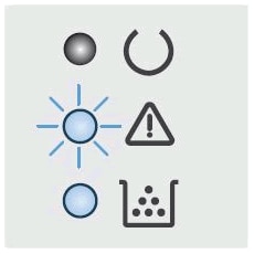
ЖК-дисплей панели управления
Кнопка со стрелкой вверх
Кнопка со стрелкой вниз
Кнопка «Начать копирование»
Кнопка «Отмена»
Кнопка «Настройка копирования»
Индикатор «Расходные материалы»
Индикатор «Внимание»
Индикатор «Готовность»
Сообщение об ошибке Er/01 означает, что входной лоток пуст. Для устранения этой ошибки убедитесь, что бумага правильно загружена во входной лоток.

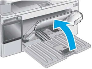
1. Поднимите пылезащитную крышку.
2. Разведите направляющие ширины и длины в крайнее положение.

3. Загрузите стопку обычной бумаги во входной лоток стороной для печати вверх, затем задвиньте стопку вперед до упора.
ПРИМЕЧАНИЕ.
Загрузите до 150 листов бумаги стороной для печати вверх и верхним краем в сторону принтера. При загрузке перфорированной бумаги загружайте бумагу отверстия к левой стороне лотка.
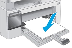
4. Придвиньте направляющие длины и ширины бумаги к краю стопки.
Слегка нажмите на края пылезащитной крышки, затем опустите ее.
Отображается Er/02 и мигает индикатор «Внимание»
Сообщение об ошибке Er/02 указывает, что верхняя крышка закрыта не полностью.
Полностью закройте верхнюю крышку, затем узел сканера.
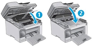
Закрывание верхней крышки
Опустите узел сканера
Отображается ошибка Er/04, Er/05 или Er/06, и мигает индикатор «Внимание»
Сообщение об ошибке Er/04, Er/05 или Er/06 обозначает замятие бумаги.
Найдите и извлеките любую замятую бумагу из принтера или перезагрузите принтер.
Отображается сообщение об ошибке Er/07, индикатор «Внимание» мигает и загорается индикатор «Расходные материалы»
Сообщение об ошибке Er/07 указывает, что картридж с тонером или барабан переноса изображений отсутствует или не установлен правильно.
Для устранения этой проблемы правильно установите отсутствующий картридж с тонером или барабан переноса изображений. Если картридж с тонером или барабан переноса изображений отсутствуют, перейдите к шагу по замене картриджа с тонером или к шагу по замене барабана переноса изображений.

Шаг 1. Извлеките и снова установите картридж с тонером
Откройте сканер и верхнюю крышку, извлеките картридж с тонером, вставьте его обратно и повторите попытку печати.
Если ошибка не устранена, перейдите к следующему шагу.
Шаг 2. Удалите и снова установите барабан переноса изображений
Откройте сканер и верхнюю крышку, извлеките барабан переноса изображений, вставьте его обратно и повторите попытку печати.
Шаг 3. Установите новый картридж с тонером
Замените картридж с тонером на новый и повторите попытку печати.
Если ошибка не устранена, перейдите к следующему шагу.
! Внимание ! Не все картриджи могут сработать на вашем принтере.
Мы предлагаем новые совместимые (лицензированные) картриджи и драм картриджи, которые 100% сработают на Вашем принтере.
Шаг 4. Установите новый барабан переноса изображений
Замените барабан переноса изображений на новый и повторите попытку печати.
Если ошибка не устранена, перейдите к следующему шагу.
Шаг 5. Обратитесь с принтером в сервисный центр
Отображается ошибка Er/08, Er/09 или Er/10, мигает индикатор «Внимание» и загорается индикатор «Расходные материалы»
Ошибка Er/08 указывает на очень низкий уровень тонера в картридже. Ошибка Er/09 указывает на очень низкий уровень барабана переноса изображений. Ошибка Er/10 указывает на очень низкий уровни картриджа с тонером и барабана переноса изображений.
M130a и M132a: Нажмите кнопку «Начать копирование»  , чтобы продолжить печать с использованием текущего картриджа с тонером. Когда качество печати станет неприемлемым, замените картридж с тонером или барабан переноса изображений.
M134a: Замените картридж с тонером или барабан переноса изображений для продолжения печати.
Шаг 1. Замените пустой картридж или картридж с низким уровнем тонера
Замените картридж с тонером на новый и повторите попытку печати. Если ошибка не устранена, перейдите к следующему шагу.
Шаг 2. Замените барабан переноса изображений
Замените барабан переноса изображений на новый и повторите попытку печати. Если ошибка не устранена, перейдите к следующему шагу.
Шаг 3. Обратитесь с принтером в сервисный центр
Отображаются ошибки Er/11–Er/19, и мигают индикаторы «Внимание» и «Расходные материалы»
Ошибки могут отображаться по следующим причинам:
Er/11, Er/14 или Er/17: Картридж с тонером не совместим с принтером, был защищен на другом принтере или не является авторизованным картриджем с тонером.
Er/12, Er/15 или Er/18: Барабан переноса изображений не совместим с принтером, был защищен на другом принтере или не является авторизованным барабаном переноса изображений.
Er/13, Er/16 или Er/19: И картридж с тонером, и барабан переноса изображений не совместимы с принтером, были защищены на другом принтере или не являются авторизованными расходными материалами.
Замените затрагиваемые расходные материалы.
Отображается ошибка Er/20, и мигают индикаторы «Внимание» и «Расходные материалы»
Сообщение об ошибке Er/20 указывает на ошибку с датчикам картриджа с тонером.
Шаг 1. Замените картридж с тонером
Для замены отсутствующего или старого картриджа с тонером откройте сканер и верхнюю крышку, извлеките старый картридж с тонером и установите новый картридж.
Шаг 2. Обратитесь с принтером в сервисный центр
Отображается Er/25 и мигает индикатор «Внимание»
Сообщение об ошибке Er/25 указывает, что размер загруженной бумаги не подходит для задания печати.
Чтобы устранить эту проблему, загрузите бумагу подходящего размера или нажмите кнопку «Начать копирование» для продолжения печати с использованием бумаги текущего размера.
Отображаются ошибки Er/30–Er/79, и мигают индикаторы «Готовность» и «Внимание»
Сообщение об ошибке Er30, Er/49, Er/50, Er/51, Er/52, Er/53, Er/54, Er/55, Er/56, Er/57, Er/58, Er/59, Er/60 или Er/79 указывает, что принтер находится в состоянии ошибки.

Шаг 1. Перезагрузите принтер
Сброс настроек принтера может устранить состояние ошибки.
Включите принтер, если он еще не включен.
Прежде чем продолжить, дождитесь полной остановки каретки.
Если принтер включен, отсоедините кабель питания от разъема на задней панели принтера.
Отсоедините кабель питания из электрической розетки.
Подождите не менее 60 секунд.
Вставьте вилку кабеля питания в розетку.
Компания HP рекомендует напрямую подключать вилку кабеля питания принтера к настенной розетке.
7. Повторно подключите кабель питания к разъему на задней панели принтера.
8. Включите принтер, если он не включается автоматически.
9. Перед продолжением дождитесь полной остановки работы принтера.
Шаг 2. Подключите вилку кабеля питания принтера напрямую в электрическую розетку
Вставьте вилку кабеля питания устройства в электрическую розетку и убедитесь в том, что источник питания исправен.
Отсоедините кабель питания из разъема на задней панели устройства.
Отсоедините кабель питания от разветвителей питания или сетевых фильтров.
Включите вилку кабеля питания непосредственно в электрическую розетку.
Подсоедините кабель питания в разъем на задней панели устройства.
Нажмите кнопку питания ( ), чтобы включить устройство.
Если проблема не устранена, попробуйте использовать другую розетку.
Шаг 3. Обратитесь с принтером в сервисный центр
На панели управления отображается ошибка Er/81, и мигает индикатор «Внимание»
Это условие означает, что загружено неверное программное обеспечение.
Отображается Go/01 и мигает индикатор «Внимание»
Это условие указывает, что принтер работает в режиме ручной подачи бумаги.
Загрузите во входной лоток бумагу размера и типа, необходимого для задания печати, затем нажмите кнопку «Начать копирование» .
Отображается Go/02 и мигает индикатор «Внимание»
Это условие указывает, что принтер обрабатывает задание ручной двусторонней печати и нуждается в вашей помощи, чтобы завершить это задание.
Чтобы завершить задание печати, извлеките стопку напечатанных листов из приемного лотка, затем загрузите стопку печатной стороной вниз и верхним краем к принтеру. Нажмите кнопку «Начать копирование» для печати второй стороны.
Все индикаторы отключены, принтер не отвечает
Такое случается, когда принтер выключен, или есть проблема блока питания.
Шаг 1. Включите принтер
Нажмите кнопку питания для включения принтера.
Если принтер не включается, перейдите к следующему шагу.
Шаг 2. Убедитесь, что принтер подключен
Убедитесь, что кабель питания подключен в разъем на задней панели принтера и к электрической розетке.
Убедитесь, что шнур питания надежно вставлен в разъем электросети.

3. Убедитесь, что шнур питания подключен к розетке электросети.
4. Включите принтер.
Если принтер не включается, перейдите к следующему шагу.
Шаг 3. Подключите вилку кабеля питания принтера напрямую в электрическую розетку
При использовании сетевого фильтра, удлинительного кабеля или фильтра бросков напряжения подключите вилку кабеля питания принтера напрямую в электрическую розетку, чтобы проверить правильность работы источника питания.
Отсоедините кабель питания от сетевых фильтров, удлинительных кабелей или фильтров бросков напряжения.
Вставьте вилку кабеля питания в розетку.
Если принтер не включается, перейдите к следующему шагу.
Шаг 4. Убедитесь в том, что настенная розетка работает
Убедитесь, что розетка, к которой подключен принтер, работает.
Отсоедините шнур питания от электрической розетки.
Подключите к розетке другое устройство и проверьте, исправна ли розетка.
Если розетка электросети не работает, подключите принтер в другую исправную розетку.
Если розетка электросети работает, но принтер не включается, переходите к следующему шагу.
Шаг 5. Проверьте питание, используя совместимый кабель от другого принтера
Если у вас имеется кабель от другого устройства, совместимый с данным принтером, воспользуйтесь им и повторите действия по подключению принтера напрямую к розетке электросети.
Если эти действия привели к устранению неполадки, дальнейшие действия не требуются.
Если принтер включается при использовании другого шнура, это означает, что причина проблемы связана с первым шнуром. Обратитесь в HP для замены шнура питания.
Нажмите ссылку Обращение в службу поддержки на этой странице, чтобы ознакомиться с дополнительными вариантами поддержки.
Если принтер не включается, перейдите к следующему шагу.
Шаг 6. Обратитесь с принтером в сервисный центр
Содержание этого документа относится к МФУ HP LaserJet Pro M130a, M132a и LaserJet Ultra M134a.
В следующих разделах описаны основные ошибки, о которых свидетельствуют сочетания мигающих индикаторов на панели управления принтера, а также способы устранения неполадок для каждой комбинации. Определите последовательность мигающих индикаторов на панели управления, затем выполните действие по устранению той или иной проблемы.
ЖК-дисплей панели управления
Кнопка со стрелкой вверх
Кнопка со стрелкой вниз
Кнопка «Начать копирование»
Кнопка «Отмена»
Кнопка «Настройка копирования»
Индикатор «Расходные материалы»
Индикатор «Внимание»
Индикатор «Готовность»
Сообщение об ошибке Er/01 означает, что входной лоток пуст. Для устранения этой ошибки убедитесь, что бумага правильно загружена во входной лоток.
1. Поднимите пылезащитную крышку.
2. Разведите направляющие ширины и длины в крайнее положение.
3. Загрузите стопку обычной бумаги во входной лоток стороной для печати вверх, затем задвиньте стопку вперед до упора.
ПРИМЕЧАНИЕ.
Загрузите до 150 листов бумаги стороной для печати вверх и верхним краем в сторону принтера. При загрузке перфорированной бумаги загружайте бумагу отверстия к левой стороне лотка.
4. Придвиньте направляющие длины и ширины бумаги к краю стопки.
Слегка нажмите на края пылезащитной крышки, затем опустите ее.
Отображается Er/02 и мигает индикатор «Внимание»
Сообщение об ошибке Er/02 указывает, что верхняя крышка закрыта не полностью.
Полностью закройте верхнюю крышку, затем узел сканера.
Закрывание верхней крышки
Опустите узел сканера
Отображается ошибка Er/04, Er/05 или Er/06, и мигает индикатор «Внимание»
Сообщение об ошибке Er/04, Er/05 или Er/06 обозначает замятие бумаги.
Найдите и извлеките любую замятую бумагу из принтера или перезагрузите принтер.
Отображается сообщение об ошибке Er/07, индикатор «Внимание» мигает и загорается индикатор «Расходные материалы»
Сообщение об ошибке Er/07 указывает, что картридж с тонером или барабан переноса изображений отсутствует или не установлен правильно.
Для устранения этой проблемы правильно установите отсутствующий картридж с тонером или барабан переноса изображений. Если картридж с тонером или барабан переноса изображений отсутствуют, перейдите к шагу по замене картриджа с тонером или к шагу по замене барабана переноса изображений.
Шаг 1. Извлеките и снова установите картридж с тонером
Откройте сканер и верхнюю крышку, извлеките картридж с тонером, вставьте его обратно и повторите попытку печати.
Если ошибка не устранена, перейдите к следующему шагу.
Шаг 2. Удалите и снова установите барабан переноса изображений
Откройте сканер и верхнюю крышку, извлеките барабан переноса изображений, вставьте его обратно и повторите попытку печати.
Шаг 3. Установите новый картридж с тонером
Замените картридж с тонером на новый и повторите попытку печати.
Если ошибка не устранена, перейдите к следующему шагу.
! Внимание ! Не все картриджи могут сработать на вашем принтере.
Мы предлагаем новые совместимые (лицензированные) картриджи и драм картриджи, которые 100% сработают на Вашем принтере.
Шаг 4. Установите новый барабан переноса изображений
Замените барабан переноса изображений на новый и повторите попытку печати.
Если ошибка не устранена, перейдите к следующему шагу.
Шаг 5. Обратитесь с принтером в сервисный центр
Отображается ошибка Er/08, Er/09 или Er/10, мигает индикатор «Внимание» и загорается индикатор «Расходные материалы»
Ошибка Er/08 указывает на очень низкий уровень тонера в картридже. Ошибка Er/09 указывает на очень низкий уровень барабана переноса изображений. Ошибка Er/10 указывает на очень низкий уровни картриджа с тонером и барабана переноса изображений.
M130a и M132a: Нажмите кнопку «Начать копирование» , чтобы продолжить печать с использованием текущего картриджа с тонером. Когда качество печати станет неприемлемым, замените картридж с тонером или барабан переноса изображений.
M134a: Замените картридж с тонером или барабан переноса изображений для продолжения печати.
Шаг 1. Замените пустой картридж или картридж с низким уровнем тонера
Замените картридж с тонером на новый и повторите попытку печати. Если ошибка не устранена, перейдите к следующему шагу.
Шаг 2. Замените барабан переноса изображений
Замените барабан переноса изображений на новый и повторите попытку печати. Если ошибка не устранена, перейдите к следующему шагу.
Шаг 3. Обратитесь с принтером в сервисный центр
Отображаются ошибки Er/11–Er/19, и мигают индикаторы «Внимание» и «Расходные материалы»
Ошибки могут отображаться по следующим причинам:
Er/11, Er/14 или Er/17: Картридж с тонером не совместим с принтером, был защищен на другом принтере или не является авторизованным картриджем с тонером.
Er/12, Er/15 или Er/18: Барабан переноса изображений не совместим с принтером, был защищен на другом принтере или не является авторизованным барабаном переноса изображений.
Er/13, Er/16 или Er/19: И картридж с тонером, и барабан переноса изображений не совместимы с принтером, были защищены на другом принтере или не являются авторизованными расходными материалами.
Замените затрагиваемые расходные материалы.
Отображается ошибка Er/20, и мигают индикаторы «Внимание» и «Расходные материалы»
Сообщение об ошибке Er/20 указывает на ошибку с датчикам картриджа с тонером.
Шаг 1. Замените картридж с тонером
Для замены отсутствующего или старого картриджа с тонером откройте сканер и верхнюю крышку, извлеките старый картридж с тонером и установите новый картридж.
Шаг 2. Обратитесь с принтером в сервисный центр
Отображается Er/25 и мигает индикатор «Внимание»
Сообщение об ошибке Er/25 указывает, что размер загруженной бумаги не подходит для задания печати.
Чтобы устранить эту проблему, загрузите бумагу подходящего размера или нажмите кнопку «Начать копирование» для продолжения печати с использованием бумаги текущего размера.
Отображаются ошибки Er/30–Er/79, и мигают индикаторы «Готовность» и «Внимание»
Сообщение об ошибке Er30, Er/49, Er/50, Er/51, Er/52, Er/53, Er/54, Er/55, Er/56, Er/57, Er/58, Er/59, Er/60 или Er/79 указывает, что принтер находится в состоянии ошибки.
Шаг 1. Перезагрузите принтер
Сброс настроек принтера может устранить состояние ошибки.
Включите принтер, если он еще не включен.
Прежде чем продолжить, дождитесь полной остановки каретки.
Если принтер включен, отсоедините кабель питания от разъема на задней панели принтера.
Отсоедините кабель питания из электрической розетки.
Подождите не менее 60 секунд.
Вставьте вилку кабеля питания в розетку.
Компания HP рекомендует напрямую подключать вилку кабеля питания принтера к настенной розетке.
7. Повторно подключите кабель питания к разъему на задней панели принтера.
8. Включите принтер, если он не включается автоматически.
9. Перед продолжением дождитесь полной остановки работы принтера.
Шаг 2. Подключите вилку кабеля питания принтера напрямую в электрическую розетку
Вставьте вилку кабеля питания устройства в электрическую розетку и убедитесь в том, что источник питания исправен.
Отсоедините кабель питания из разъема на задней панели устройства.
Отсоедините кабель питания от разветвителей питания или сетевых фильтров.
Включите вилку кабеля питания непосредственно в электрическую розетку.
Подсоедините кабель питания в разъем на задней панели устройства.
Нажмите кнопку питания (), чтобы включить устройство.
Если проблема не устранена, попробуйте использовать другую розетку.
Шаг 3. Обратитесь с принтером в сервисный центр
На панели управления отображается ошибка Er/81, и мигает индикатор «Внимание»
Это условие означает, что загружено неверное программное обеспечение.
Отображается Go/01 и мигает индикатор «Внимание»
Это условие указывает, что принтер работает в режиме ручной подачи бумаги.
Загрузите во входной лоток бумагу размера и типа, необходимого для задания печати, затем нажмите кнопку «Начать копирование» .
Отображается Go/02 и мигает индикатор «Внимание»
Это условие указывает, что принтер обрабатывает задание ручной двусторонней печати и нуждается в вашей помощи, чтобы завершить это задание.
Чтобы завершить задание печати, извлеките стопку напечатанных листов из приемного лотка, затем загрузите стопку печатной стороной вниз и верхним краем к принтеру. Нажмите кнопку «Начать копирование» для печати второй стороны.
Все индикаторы отключены, принтер не отвечает
Такое случается, когда принтер выключен, или есть проблема блока питания.
Шаг 1. Включите принтер
Нажмите кнопку питания для включения принтера.
Если принтер не включается, перейдите к следующему шагу.
Шаг 2. Убедитесь, что принтер подключен
Убедитесь, что кабель питания подключен в разъем на задней панели принтера и к электрической розетке.
Убедитесь, что шнур питания надежно вставлен в разъем электросети.
3. Убедитесь, что шнур питания подключен к розетке электросети.
4. Включите принтер.
Если принтер не включается, перейдите к следующему шагу.
Шаг 3. Подключите вилку кабеля питания принтера напрямую в электрическую розетку
При использовании сетевого фильтра, удлинительного кабеля или фильтра бросков напряжения подключите вилку кабеля питания принтера напрямую в электрическую розетку, чтобы проверить правильность работы источника питания.
Отсоедините кабель питания от сетевых фильтров, удлинительных кабелей или фильтров бросков напряжения.
Вставьте вилку кабеля питания в розетку.
Если принтер не включается, перейдите к следующему шагу.
Шаг 4. Убедитесь в том, что настенная розетка работает
Убедитесь, что розетка, к которой подключен принтер, работает.
Отсоедините шнур питания от электрической розетки.
Подключите к розетке другое устройство и проверьте, исправна ли розетка.
Если розетка электросети не работает, подключите принтер в другую исправную розетку.
Если розетка электросети работает, но принтер не включается, переходите к следующему шагу.
Шаг 5. Проверьте питание, используя совместимый кабель от другого принтера
Если у вас имеется кабель от другого устройства, совместимый с данным принтером, воспользуйтесь им и повторите действия по подключению принтера напрямую к розетке электросети.
Если эти действия привели к устранению неполадки, дальнейшие действия не требуются.
Если принтер включается при использовании другого шнура, это означает, что причина проблемы связана с первым шнуром. Обратитесь в HP для замены шнура питания.
Нажмите ссылку Обращение в службу поддержки на этой странице, чтобы ознакомиться с дополнительными вариантами поддержки.
Если принтер не включается, перейдите к следующему шагу.
Шаг 6. Обратитесь с принтером в сервисный центр
Page: 143 from 206
Схемы индикаторов панели управления (продолжение)
Состояние у принтера
Картридж с тонером или
фотобарабан отсутствует или
Установите или переустановите картридж с
тонером и фотобарабан.
Картридж с тонером несовместим
с принтером, возможно, из-за
отсутствия или повреждения
Замените картридж с тонером.
Фотобарабан несовместимы с
принтером, возможно, из-за
отсутствия или повреждения
материалов несовместимы с
принтером, возможно, из-за
отсутствия или повреждения
Замените расходные материалы.
Картридж с тонером защищен на
Замените картридж с тонером.
Фотобарабан защищен на другом
материалов защищены на другом
Замените расходные материалы.
картридж с тонером.
Замените картридж с тонером.
Замените расходные материалы.
Пояснение состояний световых индикаторов на панели управления (только модели со
-
Contents
-
Table of Contents
-
Troubleshooting
-
Bookmarks
Quick Links
Related Manuals for imagistics im2330
Summary of Contents for imagistics im2330
-
Page 2
Specifically, this copier complies with the following requirements. im2330/im2830 Copier model (Base model) ‘Automatic Energy Save’- The copier consumes less than 93.55 W (im2330)/112.80 W (im2830) during Energy Save. ‘Automatic Energy Save’ Default Time- The default time for the ‘Automatic Energy Save’ is 15 minutes. -
Page 3: Table Of Contents
CONTENTS Notice to Users ……………………….5 Imagistics Quality is Second to None ………………….6 Preface …………………………8 im2330/im2830 Features …………………….9 General Precautions ……………………..10 • When installing or moving ……………………10 • When using the Multifunctional Digital Systems……………..13 • During maintenance or inspection………………….16 • When handling supplies ……………………17 Disclaimer Notice………………………18…
-
Page 4
CONTENTS (Cont.) 5. USING THE EDITING FUNCTIONS………………..127 1. IMAGE SHIFT ……………………..128 2. EDGE ERASE……………………..134 3. BOOK CENTER ERASE……………………135 4. DUAL PAGE ……………………..137 5. 2IN1 / 4IN1………………………..139 6. MAGAZINE SORT …………………….142 7. EDITING ……………………….144 • Trimming / Masking ……………………144 • Mirror image……………………..147 •… -
Page 5
11.MAINTENANCE……………………..311 1. Daily Inspection……………………..312 2. Simple Troubleshooting …………………….314 12.SPECIFICATIONS & OPTIONS ………………….319 1. im2330/im2830 Specifications …………………..320 2. Specifications of Options …………………..323 3. Packing List……………………….328 4. Copying Function Combination Matrix ……………….329 • Combination Matrix 1/2……………………329 • Combination Matrix 2/2……………………330… -
Page 6
CONTENTS (Cont.) -
Page 7: Notice To Users
WARNING Changes or modification made to this equipment, not expressly approved by Imagistics or parties autho- rized by Imagistics, could void the user’s authority to operate the equipment. This Class A digital apparatus complies with Canadian ICES-003.
-
Page 8: Imagistics Quality Is Second To None
Imagistics Quality is Second to None im2330/im2830 Toner Cartridges. It is recommended that genuine Imagistics supplies and parts be used to obtain optimum results.
-
Page 9
Genuine Imagistics supplies are designed to provide consistently stable image output. • Copier Kind Genuine Imagistics supplies are designed to keep the copier and all its parts in trouble-free working order. Reduction of machine wear is due to Imagistics’ intimate knowledge of the copier’s characteristics ensuring the highest standard of care. -
Page 10: Preface
Operator’s Manual should be readily available for future reference. To ensure correct and safe use of the Imagistics Multifunctional Digital Systems im2330/im2830, this Operator’s Manual describes safety precautions according to the following three levels of warning: Before reading this Operator’s Manual, you should fully understand the meaning and importance of…
-
Page 11: Im2330/Im2830 Features
The im2330/im2830 offers the following convenient features, functions and options. • The copying speed is, 23 copies (LT) per minute for im2330, 28 copies (LT) per minute for the im2830. • Considering eco-friendliness and energy saving, the used toner free recycle system is adopted, warm- up time is shortened to approximately 25 seconds and the ozone generation amount in the equipment is reduced by 75% compared with current models.
-
Page 12: General Precautions
General Precautions When installing or moving Warning • This Multifunctional Digital Systems requires 115 V, 12 A, 50/60 Hz electric power. Do not use a power supply with a voltage other than that specified. Avoid multiple connections in the same outlet. This could cause a fire or give you an electric shock. If you are considering increasing the number of outlets, contact an electrician.
-
Page 13
Caution • Do not tilt the Multifunctional Digital Systems more than 10 degrees when moving it. If it falls, this could result in personal injury. • Avoid placing the Multifunctional Digital Systems in a place unsuitable for its weight and also make sure the surface is level. -
Page 14
General Precautions (Cont.) Other points • Make sure that there is enough space around the system to facilitate changing of parts, maintenance and clearing paper jam. If there is insufficient space, some operations, such as bypass feeding, will become difficult and the Multifunctional Digital Systems could even break down. -
Page 15: When Using The Multifunctional Digital Systems
When using the Multifunctional Digital Systems Warning • Do not place metallic objects or containers with water (flower vases, coffee cups, etc.) on or near the Multifunctional Digital Systems. And keep paper clips and staples away from the air vent. This could cause a fire or give you an electric shock.
-
Page 16
General Precautions (Cont.) Position of Certification label, etc. Explanatory label Certification label Identification label Warning label 1, 3, 4:Warning for high temperature areas (Fuser unit) 2, *2: Warning for high temperature areas (Ventilation holes) Warning for high temperature areas (Drum) -
Page 17
Other points • Be very careful to treat the touch panel gently and never hit it. Breaking the surface could cause mal- functions. • Do not turn the power OFF with jammed paper left inside the Multifunctional Digital Systems. This could cause malfunctions when the main switch is turned ON next time. To turn the power OFF, see P.37 “Shutdown”. -
Page 18: During Maintenance Or Inspection
General Precautions (Cont.) During maintenance or inspection Warning • Never attempt to repair, disassemble or modify the Multifunctional Digital Systems by yourself. You could cause a fire or get an electric shock. Always contact your Service representative for maintenance or repair of the internal parts of the Multi- functional Digital Systems.
-
Page 19: When Handling Supplies
When handling supplies Caution • Never attempt to incinerate toner cartridges. Dispose of used toner cartridges in accordance with local regulations. ( P.264 “3.Replace Toner Cartridge Symbol”)
-
Page 20: Disclaimer Notice
2. All warranties, conditions and other terms implied by law are, to the fullest extent permitted by law, excluded and no such implied warranties are given or apply in relation to the Products. 3. Imagistics International Inc. shall not be liable for any loss, cost, expense, claim or damage whatso- ever caused by any of the following: (a) use or handling of the Product otherwise than in accordance with the manuals, including but not limited to Operator’s Manual, User’s Guide, and/or incorrect or careless handling or use of the Product;…
-
Page 21: Before Using Equipment
1. BEFORE USING EQUIPMENT 1. Description of Each Component ………………20 • Main components……………………..20 • Configuration of options ……………………21 • Control panel………………………..23 • Adjustment of the angle of the control panel………………25 • Touch panel……………………….27 2. Turning Power On / Shutdown …………………31 •…
-
Page 22: Description Of Each Component
Drawer (im2330/im2830) Inner tray Slot cover (NA) 10. Control panel Operator’s manual pocket (back side) 11. Touch panel Power switch 12. Touch panel contrast adjustment dial Automatic duplexer 13. Toner (standard on the im2330/im2830) *A and B: Options 1.BEFORE USING EQUIPMENT…
-
Page 23: Configuration Of Options
This feeder enables you to feed up to 2500 sheets (20 lb. Bond) of LT paper. 6. Paper Feed Pedestal (9281) Adds one drawer to the equipment. 7. Additional Drawer Module (9282) Enables one drawer to be added to the Paper Feed Pedestal. The 2nd drawer is standard on the im2330/im2830.
-
Page 24
This unit enables you to punch holes on printouts. It can be installed to the Saddle Stitch Finisher (9256). 12. Automatic Duplexer Enables duplex copying. Standard on the im2330/im2830. Other options available are as follows. Contact your service technician or Imagistics product distributors for details. Work Table (cm4530070) FAX Unit (cm4530110) 2nd Line for Fax Unit (cm4530120) -
Page 25: Control Panel
Control panel Use the buttons on the control panel for various operations and settings through the equipment. 10 11 1. [HELP] button Use this button to display a desired operation procedure. 2. [USER FUNCTIONS] button Use this button for paper size or media type setting of drawers, and registration of the copy, scan and FAX settings (including a default setting change.) See the User Functions Guide for the functions enabled by this button.
-
Page 26
1.Description of Each Component (Cont.) 11. [JOB STATUS] button Use this button to confirm the job status, printing status, and FAX transmission/reception status of a print job, scan job and FAX job. ( P.224 “1.Job Status”) 12. [ACCESS] button Use this button when the department code or user information has been set. If this button is pressed after copying, the next user cannot use functions such as copying without keying in the department code or user information. -
Page 27: Adjustment Of The Angle Of The Control Panel
Adjustment of the angle of the control panel When adjusting the angle of the control panel The angle of the control panel is adjustable at any angle between 7 and 45 degrees from the horizontal position. When changing the angle of the control panel, be careful not to catch your hands in the gap between the equipment and the control panel.
-
Page 28
1.Description of Each Component (Cont.) Fit the latches of the stopper in the hole of the position B and insert them turning the stopper itself. Shift the stopper to the left until it clicks. • The angle of the control panel is fixed at 7 degrees. 1.BEFORE USING EQUIPMENT… -
Page 29: Touch Panel
Touch panel When the power is turned on, the basic menu for the copier function appears on this touch panel. The sta- tus of the equipment is also displayed on the touch panel with messages and illustrations. Message 10. Original mode button Reproduction ratio 11.
-
Page 30
1.Description of Each Component (Cont.) [SETTINGS] button Press this button to confirm currently set functions. (An example is shown below.) Buttons appearing on the various menus are as follows (some buttons may not appear on the menu): 1.BEFORE USING EQUIPMENT… -
Page 31: Adjusting The Contrast Of The Touch Panel
Clearing functions selected When you press the selected button, the function which has been selected is cleared. Or the selected set- ting is cleared automatically by the automatic function clear* when the equipment has been left inactive for a specified period of time. Automatic function clear: This function works when a specified period of time has passed since the last paper exit or the last entry of any button.
-
Page 32: Setting Letters
1.Description of Each Component (Cont.) Setting letters The following menu appears when any letter entry is required for the operations of scanning, e-Filing, tem- plate and Internet FAX. Use the buttons on the touch panel for letter entry and use the digital keys on the control panel for number entry.
-
Page 33: Turning Power On / Shutdown
2. Turning Power On / Shutdown Turning power on Open the switch cover, and then turn the power switch on. • The equipment starts warming-up. “Wait Warming Up” appears during warming-up. • While the equipment is warming up, you can use the auto job start function. P.66 “Scanning the next originals during copying (Auto job start)”) The equipment will be ready for copying after about 25 seconds and “READY”…
-
Page 34: When Department Or User Management Is Used
2.Turning Power On / Shutdown (Cont.) When department or user management is used When the use of the equipment is managed under department management or user management func- tion, each user needs to enter the department code or user information. Department management You can restrict users or manage copy volumes made by an individual group or department in your com- pany using the department codes.
-
Page 35: User Management
User management In the user management function, the users of the equipment can be limited or the past record of each user can be managed. When the equipment is managed under this function, turn the power of the equip- ment ON and enter the information required (e.g. user name, password) to use the equipment. The menu for entering user information also appears when you pressed the [ACCESS] button on the control panel or automatic function clear has worked.
-
Page 36
2.Turning Power On / Shutdown (Cont.) Press the [USER NAME] button. Enter the user name (maximum 128 letters) and then press the [ENTER] button. Press the [PASSWORD] button. 1.BEFORE USING EQUIPMENT… -
Page 37
Enter the password (maximum 64 letters) and then press the [ENTER] button. Press the [ENTER] button. The menu will switch and the equipment will be ready to be used. • If the user information is incorrectly entered, the menu will not switch. In this case, press the [FUNCTION CLEAR] button and then enter it again. -
Page 38
2.Turning Power On / Shutdown (Cont.) When copying is finished When you finish all operations, press the [ACCESS] button to prevent unauthorized use of the equipment. The display returns to the one for entering user information. 1.BEFORE USING EQUIPMENT… -
Page 39: Shutdown
Shutdown Be sure to shut down the equipment following the procedure below. Do not turn the power off by pressing the power switch, otherwise the hard disk may be damaged. Be sure to confirm the following three points before shutdown. •…
-
Page 40
2.Turning Power On / Shutdown (Cont.) “Shutdown in progress” appears on the menu. After a while, the equipment is shut down. • The power switch automatically returns to the OFF position. Shutting down with the [ENERGY SAVER] button The equipment can also be shut down by following the procedure below. Press the [ENERGY SAVER] button on the control panel. -
Page 41
“Shutdown in progress” appears on the menu. After a while, the equipment is shut down. • The power switch automatically returns to the OFF position. -
Page 42: Energy Saving Mode
3. Energy Saving Mode This equipment is designed to enter into the energy saving mode automatically to lower its power con- sumption when a specified period of time has passed since the last use of the equipment (=automatic energy saving mode). In this mode, “Saving energy — press START button” appears. Then after a certain period of time, the display on the touch panel disappears and the [ENERGY SAVER] button lights in green.
-
Page 43: Setting Copy Paper
4. Setting Copy Paper About the “width” and the “length” of the original and the copy paper Originals and copy paper whose size is LT can be set in both portrait and landscape directions. In the size descriptions of original and copy paper throughout this manual, “A” in the figure below is called “length” and “B”…
-
Page 44: Acceptable Copy Paper
*2 Use Thick 2 mode for sticker labels. • Multiple paper sizes cannot be set in one drawer. • “Maximum sheet capacity” refers to the maximum number of sheets when Imagistics-recommended paper is set. • “K format” is a Chinese standard size.
-
Page 45: Recommended Paper
OHP Film Envelope Westvaco Columbian CO138 ENVELOPE Mailwell No. 553 *1 Only Imagistics-recommended OHP film should be used. Using any other film may cause a malfunc- tion. Handling and storing paper Pay attention to the following points: • Avoid using paper that is specially treated or previously printed on another machine, and also avoid performing double copying on the same side of the paper, since this may cause a malfunction.
-
Page 46: Setting Copy Paper (Size Change)
4.Setting Copy Paper (Cont.) Setting copy paper (size change) When you set or add copy paper in the drawer, follow the procedure below. Placing paper in the drawer Turn the power on. Pull out the drawer carefully until it comes to a stop. Push the lower part of the end guide in the direction of the arrow to remove it, then reinstall it at the desired paper size…
-
Page 47: Side Guide
While pushing the green lever of the side guide in the direction of the arrow, set the side guide to the desired paper size. • Adjust the side guides with both hands. Push the arrow part (left side) to lock the side guide.
-
Page 48
4.Setting Copy Paper (Cont.) Push the drawer straight into the equipment until it comes to a stop. • Be sure to close the drawer securely and carefully. Be careful not to let your fingers be caught when closing the drawer. This could injure you. When the paper size is different from the one in the drawer, change the paper size indicator to match with the size of paper… -
Page 49
Press the paper size button corresponding to the paper that has been set in the drawer. When you want to change the setting of the drawer for special uses P.50), press the paper type button. Press the [ENTER] button. -
Page 50: Changing The Setting Of Paper Size
4.Setting Copy Paper (Cont.) Changing the setting of paper size If the setting of the paper size registered in the equipment does not correspond to the one in the drawer, it could cause a paper jam. In this case, change the setting of the paper size according to the following pro- cedure.
-
Page 51: Placing Paper In The Large Capacity Feeder (Optional)
Placing paper in the Large Capacity Feeder (optional) Pull out the Large Capacity Feeder care- fully. • Pull out the drawer until it comes to a stop. Place paper in A and B. • Place paper with its copy side up. (The copy side may be described on the wrapping paper.) •…
-
Page 52: Drawer For Special Uses
4.Setting Copy Paper (Cont.) Drawer for special uses When you set paper for special uses other than normal copying (e.g. sheets for cover copying) in the drawer, you need to set this drawer for the special use in advance. If the drawer has been set for a special use, its indication will change on the touch panel.
-
Page 53
Press the [USER] button on the touch panel to enter the user setting menu, then press the [DRAWER] button. Press the desired drawer and paper type button on the touch panel. E. g.: When “Cover sheet” is set in the 1st drawer. -
Page 54: Clearing The Drawer For Special Uses
4.Setting Copy Paper (Cont.) Clearing the drawer for special uses Follow steps 1 to 3 of “Setting the drawer for special uses” ( P.50). Press the drawer on the touch panel corresponding to the one whose setting you want to clear, and then press the button indicating the paper type in this drawer.
-
Page 55: How To Make Copies
2. HOW TO MAKE COPIES 1. Setting Originals……………………54 • Acceptable originals ……………………..54 • Placing originals on the glass………………….56 • Using the Reversing Automatic Document Feeder (optional) …………58 2. Making Copies ……………………61 • Initial (Default) settings……………………61 • Copying procedure……………………..62 • Scanning the next originals during copying (Auto job start) …………..66 •…
-
Page 56: Setting Originals
1. Setting Originals Acceptable originals Acceptable originals are as follows. Maximum Acceptable sizes for automatic size Setting position Type of original size detection Sheets Length: 11.69″ (Standard size) Original glass 3-dimensional Width: 17.01″ LD, LG, LT, LT-R, ST-R object Books Reversing Auto- Plain paper Length: 11.69″…
-
Page 57: Maximum Number Of Sheets For Scanning
Maximum number of sheets for scanning A maximum of 1000 LT sheets, or up until the memory becomes full can be accepted per 1 copy job. When the number of scanned sheets has exceeded the above limit, a message “The number of originals exceeds the limits.
-
Page 58: Placing Originals On The Glass
1.Setting Originals (Cont.) Placing originals on the glass Sheet originals Do not place heavy objects (9 lb. or more) on the original glass and do not press on it with force. Breaking the glass could injure you. Raise the original cover or Reversing Automatic Document Feeder (optional).
-
Page 59: Book-Type Originals
Book-type originals Do not place heavy objects (9 lb. or more) on the original glass and do not press on it with force. Breaking the glass could injure you. Raise the original cover or Reversing Automatic Document Feeder (optional). Open the desired page of the original and place it face down.
-
Page 60: Using The Reversing Automatic Document Feeder (Optional)
1.Setting Originals (Cont.) Using the Reversing Automatic Document Feeder (optional) Precautions Do not use the types of original 1 to 8 shown below because such types may cause misfeeding or damage to the equipment. 1. Badly wrinkled, folded or curled originals 2.
-
Page 61: Continuous Feed Mode
Continuous feed mode Align all the originals. Then place them face up and align the side guides to the original length. • Place the originals straight along the side guides. • Collate the originals in the order that you want them to be cop- ied.
-
Page 62: Single Feed Mode
1.Setting Originals (Cont.) Single feed mode To switch over between the continuous feed mode and the single feed mode, see P.168 “16.ADF / SADF”. Align the side guides to the original width. Insert the original with its face up and straight along the side guides.
-
Page 63: Making Copies
2. Making Copies Initial (Default) settings When the power is turned on, when the energy saving mode is cleared, and when the [FUNCTION CLEAR] button on the control panel is pressed, various setting items are automatically set. These items are called the initial (default) settings. Set originals after placing paper or confirming that there is paper in the drawers.
-
Page 64: Copying Procedure
2.Making Copies (Cont.) Copying procedure Placing originals on the Reversing Automatic Document Feeder (optional) Place paper in the drawer(s). • For the types and sizes of paper selectable, see P.42 “Acceptable copy paper”. When the desired size or type of paper is not in any of the drawers or the Large Capacity Feeder, see the follow- ing pages.
-
Page 65
Press the [START] button. • Copying starts. The paper exits with its copied side down. • When the drawer runs out of paper during copying, the corre- sponding drawer on the touch panel and the [JOB STATUS] but- ton on the control panel blink. Add paper to this drawer or select another one with the same paper size. -
Page 66
2.Making Copies (Cont.) Press the [START] button. Copying starts. • When you copy by placing originals on the original glass (e.g. using the sort mode, or making 1-sided original 2-sided copies), the data of these originals are scanned into the memory. In this case, proceed to steps 5 and 6. -
Page 67: Stopping The Copying Operation
Stopping the copying operation Press the [STOP] button on the control panel to stop scanning or continuous copying. Press the [STOP] button on the control panel during scanning (or continuous copying). When the following menu is displayed, press the [MEMORY CLEAR] button on the touch panel.
-
Page 68: Scanning The Next Originals During Copying (Auto Job Start)
2.Making Copies (Cont.) Scanning the next originals during copying (Auto job start) You can reserve a copy job by scanning the original during continuous copying or while “READY (WARM- ING UP)” appears. Place the original(s). Select the copy mode and set the number of copies. Note that the job starts in the copy modes of the previous job unless you set new ones particularly for this job.
-
Page 69: Confirming And Canceling Auto Job
Confirming and canceling auto job Confirming auto job and canceling job in waiting Press the [JOB STATUS] button on the control panel to display the job list for confirming the set auto job and canceling a job waiting to be copied. To cancel auto jobs, see P.226 “Deleting print jobs”.
-
Page 70: Interrupt Copying In Progress And Make Other Copies (Interrupt Copying)
2.Making Copies (Cont.) Interrupt copying in progress and make other copies (Interrupt copying) While continuous copying is in progress, you can interrupt this job with another copy job. The following features cannot be used together with interrupt copying: • Cover sheet copying •…
-
Page 71: Bypass Copying
3. Bypass Copying Bypass copying When you want to make copies on OHP film, sticker labels, envelopes, or non-standard size paper, place the sheets of paper on the bypass tray. Bypass copying is also recommended for copying on standard size paper which is not in any of the drawers.
-
Page 72: Bypass Copying On Standard Size Paper
3.Bypass Copying (Cont.) Bypass copying on standard size paper Copying on LD, LT, LG and ST-R size paper Place some sheets of paper with their copy side down on the bypass tray. Align the side guides to the paper length while holding A.
-
Page 73
Press the [MEDIA TYPE] button on the touch panel if the media type of the paper you have set on the tray is other than plain paper. Press the button of the same media type as the one of the paper you have set on the tray, and then press the [ENTER] button on the touch panel. -
Page 74
3.Bypass Copying (Cont.) Copying on standard size paper other than LD, LT, LG and ST-R Place paper and original(s) by following step 1 and 2 in “Copying on LD, LT, LG and ST-R size paper” ( P.70). Press the [OTHER SIZE] button on the touch panel. Press the button of the same size as the one of the paper you have set on the tray. -
Page 75
Press the [MEDIA TYPE] button on the touch panel if the media type of the paper you have set on the tray is other than plain paper. Press the button of the same media type as the one of the paper you have set on the tray, and then press the [ENTER] button on the touch panel. -
Page 76: Copying On An Envelope
3.Bypass Copying (Cont.) Copying on an envelope Acceptable envelope The acceptable envelope sizes are as follows. • CHO-3 (120 mm x 235 mm), YOU-4 (105 mm x 235 mm), COM10 (4 ” x 9 ”), Monarch (3 ” x 7 ”), DL (110 mm x 220 mm) The recommended envelope COM10…
-
Page 77
Copying on an envelope The copied envelope exits into the inner tray regardless of the finisher (option). Pick up about 5 envelopes, fan the enve- lopes well and align the edges. Place the envelopes on a flat clean sur- face and press them with your hands in the direction of the arrow to expel any air. -
Page 78
3.Bypass Copying (Cont.) Place the original on the original glass. Press the [OTHER SIZE] button on the touch panel. Press the envelope size button corresponding to the envelope placed on the bypass tray. • “ENVELOPE” is automatically selected for paper type. 2.HOW TO MAKE COPIES… -
Page 79
Press the [OTHER] button. Set other copy modes as required. Press the [START] button. • The envelope exits into the inner tray. • Every 10 copies, take the envelopes out from the inner tray. -
Page 80: Bypass Copying On Non-Standard Size Paper
3.Bypass Copying (Cont.) Bypass copying on non-standard size paper Non-standard size paper should be within the following ranges: A (Length): 3.9″ to 11.7″, B (Width): 5.8″ to 17″ Place some sheets of paper with their copy side down on the bypass tray. Align the side guides to the paper length while holding A.
-
Page 81
Press the [NON STANDARD] button on the touch panel. Set each dimension following the procedure below. The [Length] and [Width] are indicated as follows: A: [Length] B: [Width] Using the digital keys Key in the value in [Length] and press the [SET] button on the touch panel. Set the width in the same way and press the [ENTER] button. -
Page 82: Registering Non-Standard Size In The Memory
3.Bypass Copying (Cont.) Recalling dimensions registered in the memory Press the desired memory number button from [MEMORY 1] to [MEMORY 4] to recall the dimension data registered previously, and then press the [ENTER] button. • Paper size that can be set is as follows: Length: 100 mm (3.94″) to 297 mm (11.69″) Width:…
-
Page 83
Key in each dimension, and press the [MEMORY] button on the touch panel. • Key in its length in [Length] and press the [SET] button on the touch panel. Set its width in the same manner. • Paper size that can be set is as follows: Length: 100 mm (3.94″) to 297 mm (11.69″) Width: 148 mm (5.83″) to 432 mm (17.01″) -
Page 84: Proof Copy
4. Proof Copy This function allows you to check that the copy density, zoom and margin width, etc. are properly set by making only one set of copies. You can prevent miscopying by using this function before committing yourself to mass-copying. •…
-
Page 85
Change the settings as required. • The setting of the number of the copy sets, page number, time stamp, sort/stapling (when the optional Finisher has been installed) and hole punch (when the optional Hole Punch Unit has been installed) can be changed. •… -
Page 86
2.HOW TO MAKE COPIES… -
Page 87: Setting Of Basic Copy Modes
3. SETTING OF BASIC COPY MODES 1. Paper Selection……………………86 • Automatic Paper Selection (APS) …………………86 • Manual paper selection ……………………88 • Copying mixed-size originals in one go (mixed original size)…………89 2. Enlargement and Reduction Copying ………………91 3. Selecting Finishing Modes ………………..97 •…
-
Page 88: Paper Selection
1. Paper Selection Automatic Paper Selection (APS) When you place standard size originals on the original glass or the Reversing Automatic Document Feeder (optional), the size of the originals is automatically detected, which helps the equipment select paper that is the same size as the originals. •…
-
Page 89
When automatic paper selection is not selected (1) Press the Enlargement/Reduction ([ZOOM…]) button. (2) Press the [APS] button. Press the [START] button. -
Page 90: Manual Paper Selection
1.Paper Selection (Cont.) Manual paper selection Automatic paper selection cannot be selected for the following originals because their sizes are not detected correctly. Select the paper size manually for these originals. • Highly transparent originals (e.g. OHP film, tracing paper) •…
-
Page 91: Copying Mixed-Size Originals In One Go (Mixed Original Size)
Copying mixed-size originals in one go (mixed original size) You can copy a set of originals whose sizes are individually different, using the Reversing Automatic Doc- ument Feeder (optional), by pressing the [MIXED ORIGINAL SIZE] button. • This mixed original size setting is available only in the following combinations. LD, LG, LT, LT-R, 8.5″, SQ, COMP •…
-
Page 92
1.Paper Selection (Cont.) Select either automatic paper selection (APS) or automatic magnifica- tion selection (AMS). Automatic paper selection: Copies on the same size of paper as that of originals ( P.86). Automatic magnification selection: Copies all in one size ( P.91). -
Page 93: Enlargement And Reduction Copying
2. Enlargement and Reduction Copying You can enlarge or reduce the size of copies by means of the following procedures. • Specifying the copy paper size in advance so that the equipment will detect the original size and auto- matically select the most appropriate reproduction ratio for the copy paper size (= automatic magnifica- tion selection) •…
-
Page 94
2.Enlargement and Reduction Copying (Cont.) Press the button representing the desired copy paper size. • The copy paper size can also be set by pressing the drawer button on the touch panel. Press the [AMS] button. Place the original(s). • When the original is placed, the equipment detects the original size, then computes and displays the most appropriate reproduction ratio for the specified copy paper size. -
Page 95: Specifying Both Original Size And Copy Size Separately
Specifying both original size and copy size separately Place paper in the drawer(s). Place the original(s). Press the Enlargement/Reduction ([ZOOM…]) button. Specify the original size and copy paper size. Original size: Press the size button representing the same size as that of the set original. Copy paper size: Press the size button representing the desired copy paper size.
-
Page 96
2.Enlargement and Reduction Copying (Cont.) When a standard size paper other than LD, LG, LT and ST-R is set Register the size of the placed paper to the [OTHER] button with the following procedure. The registered paper size is automatically selected when the [OTHER] button is pressed. Press the [OTHER SIZE] button. -
Page 97
Using the zoom buttons or the one-touch zoom buttons Place paper in the drawer(s). Place the original(s). Press the Enlargement/Reduction ([ZOOM…]) button. Press the following buttons to set the desired reproduction ratio. A: Zoom ([ Up] and [ Down]) buttons The reproduction ratio changes by 1% every time it is pressed. -
Page 98
2.Enlargement and Reduction Copying (Cont.) Press the button representing the desired copy paper size. • The copy paper size can also be set by pressing the drawer button on the touch panel. • Set other copy modes as required. Press the [START] button. 3.SETTING OF BASIC COPY MODES… -
Page 99: Selecting Finishing Modes
3. Selecting Finishing Modes Type of finishing mode The available finishing modes differ depending on the type of finishing device installed (9256, 9284, im2300030, im2300040 or IM2300030). Check the available finishing modes with the table below. Yes: Available No: Not available Type of finishing mode Maga- Finishing device…
-
Page 100: Name Of Each Part In The Finisher (Optional)
3.Selecting Finishing Modes (Cont.) Name of each part in the Finisher (optional) 1. Tray 2. Sub-tray 3. Upper cover 4. Hole Punch Unit (IM2300030) 5. Front cover 6. Saddle stitch tray MJ-1025 MJ-1022 3.SETTING OF BASIC COPY MODES…
-
Page 101
Names of each Inner Finisher (optional) 1. Trays 2. Paper stopper MJ-5004 MJ-5005… -
Page 102: Sort/Group Copying
3.Selecting Finishing Modes (Cont.) Sort/Group copying To make multiple copies, select the sort mode or the group mode as required. (Example of making 5 sets of copies from 5 original sheets) 1. Sort copying 2. Group copying When you use the LD or LG size copy paper, pull out the sub-tray in advance. The copied paper may fall or may not be sorted properly without the sub-tray.
-
Page 103
Press the [SORT] (or [GROUP]) button. • Set other copy modes as required. Press the [START] button. -
Page 104: Rotate Sort Mode
3.Selecting Finishing Modes (Cont.) Rotate sort mode In the rotate sort mode, one set of copies is made to exit on another set of copies, being alternated length- wise or crosswise. The available paper sizes for this mode is LT/LT-R. Set the LT/LT-R size paper in the drawers in advance. •…
-
Page 105: Staple Sort Mode
Staple sort mode When the Finisher (optional) is installed, automatic stapling is enabled. You can select the stapling position from three types. • The paper quantity and weight applicable for this mode differ depending on the Finisher installed in this equipment.
-
Page 106: Maximum Number Of Sheets For Stapling
3.Selecting Finishing Modes (Cont.) Press the [FRONT STAPLE] (or [DOUBLE STAPLE] or [REAR STA- PLE]) button. • For the Hanging Finisher (9284), only the [FRONT STAPLE] button can be selected. • Set other copy modes as required. Press the [START] button. If the paper quantity exceeds the maximum number of sheets that can be stapled, the Finisher automatically enters the sort mode.
-
Page 107: Magazine Sort & Saddle Stitch Mode (Booklet Mode)
Magazine sort & saddle stitch mode (booklet mode) In the magazine sort mode, more than one original can be copied and bound like magazines or booklets. Also, a set of copied sheets can be automatically folded and stapled at its center when the Saddle Stitch Finisher (optional) is installed.
-
Page 108
3.Selecting Finishing Modes (Cont.) Place paper in the drawer(s). Select the paper size. • Available copy paper sizes are LD, LT-R and LG. • For bypass copying, see P.69 “3.Bypass Copying”. Place the original(s). • When placing originals on the Reversing Automatic Document Feeder, see the illustrations ( P.105) for the proper page order of the copies. -
Page 109
Available conditions for saddle stitching Available paper sizes are LD, LT-R and LG. Maximum Paper size Paper weight capacity for sad- Tray load capacity dle stitch LD, LT-R, A3, A4- Plain paper 10 sheets Copying of 6-10 sheets: 10 sets R, B4 17-20 lb. -
Page 110: Hole Punch Mode (Optional)
3.Selecting Finishing Modes (Cont.) Hole punch mode (optional) When the Hole Punch Unit (optional) is installed to the Saddle Stitch Finisher (optional), you can punch holes in the copies. • The available copy paper sizes for this mode are LD, LG, LT, LT-R and COMP. •…
-
Page 111
Number of punch holes and available paper sizes Since the number of punch holes and the distance between the holes vary depending on the country/ region, purchase a hole punch unit that meets your requirements. (For details, consult your service techni- cian.) Number of punch holes Available paper sizes… -
Page 112: Duplex Copying
4. Duplex Copying The following 5 combinations are available for duplex copying. 1. 1-sided original -> 1-sided copy (default setting at installation) 2. 1-sided original -> 2-sided copy 3. 2-sided original -> 2-sided copy 4. 2-sided original -> 1-sided copy 5.
-
Page 113
1-sided original -> 1-sided copy (default setting at installation) Place paper in the drawer(s). Place the original(s). Confirm that the simplex/duplex button on the basic menu is [1 -> 1 SIMPLEX]. • If [1 -> 1 SIMPLEX] is not shown, press the simplex/duplex button to display the next menu, and then press the [1 ->… -
Page 114
4.Duplex Copying (Cont.) 1-sided original -> 2-sided copy When you copy 1-sided portrait originals to 2-sided copies, you can make a booklet-type copy in the direc- tion of “open to left” opening, using the image direction mode in the edit menu. ( P.164 “14.IMAGE DIRECTION”) Place paper in the drawer(s). -
Page 115
2-sided original -> 2-sided copy Place paper in the drawer(s). • When using this mode in bypass copying, specify the paper size in advance. ( P.69 “3.Bypass Copying”) Place the original(s). Press the simplex/duplex button on the basic menu. Press the [2 -> 2 DUPLEX] button. •… -
Page 116
4.Duplex Copying (Cont.) 2-sided original -> 1-sided copy When a 2-sided ‘open to left’ (Book) portrait original is copied using the image direction mode in the edit menu with [2-Sided Originals to 1-Sided Copies], copies can be adjusted to the same direction. ( P.164 “14.IMAGE DIRECTION”) Place paper in the drawer(s). -
Page 117
Book-type original -> 2-sided copy You can make a booklet-type copy in the same page configuration in which the original is. • The acceptable paper size for this function is LT only. Place paper in the drawer(s). • When using this mode in bypass copying, specify the paper size in advance. ( P.69 “3.Bypass Copying”) Press the simplex/duplex button on the basic menu. -
Page 118
4.Duplex Copying (Cont.) Select the book copying type. • Press the [RIGHT -> RIGHT] button (= default setting at the installation) if copying should start at a right-hand page and end at a right-hand page. Other copying types are selectable by pressing any of the [RIGHT -> LEFT], [LEFT ->… -
Page 119: Original Glass
Select LT copy size. • Only LT size is available. Press the drawer button on the touch panel, or use the paper source selection ( / ) buttons to select LT size. • If you need a binding space, select the book margin mode. ( P.128 “1.IMAGE SHIFT”) •…
-
Page 120
4.Duplex Copying (Cont.) When all the pages have been scanned, press the [FINISHED] button on the touch panel. • The scanned pages will be copied. • For setting image shift, see P.132 “Creating a bookbinding margin”. 3.SETTING OF BASIC COPY MODES… -
Page 121: Original Mode
5. Original Mode You can make copies with optimal image quality by selecting the following modes for your original. TEXT/PHOTO: Originals with text and photographs mixed (Default setting) TEXT: Originals with text (or text and line art) only PHOTO: Originals with photographs Place paper in the drawer(s).
-
Page 122: Copy Density Adjustment
6. Copy Density Adjustment There are 2 types of copy density adjustment: the automatic copy density mode and the manual copy den- sity mode. In the automatic copy density mode, the equipment automatically selects the most appropriate copy density by detecting the density of the original. In the manual copy density mode, you can adjust the copy density manually according to the conditions of the original.
-
Page 123: Manual Copy Density Mode
Manual copy density mode Place paper in the drawer(s). Place the original(s). Press either the button to adjust the copy density to the desired level. • The copied image becomes lighter as you press the button and darker as you press the button.
-
Page 124
3.SETTING OF BASIC COPY MODES… -
Page 125: Image Adjustment
4. IMAGE ADJUSTMENT 1. Background Adjustment …………………124 2. Sharpness ……………………..125…
-
Page 126: Background Adjustment
1. Background Adjustment This function allows you to adjust the density of the original’s background. It avoids the back side of 2- sided originals becoming visible on the front side of the original through the copy. • This mode cannot be used with the automatic copy density mode. ( P.120) Place paper in the drawer(s).
-
Page 127: Sharpness
2. Sharpness This function allows you to emphasize or blur the outline of the image. When the sharpness level is adjusted to the [SOFT] side, the moire fringes are suppressed. If it is adjusted to the [SHARP] side, the let- ters and fine lines become sharper.
-
Page 128
4.IMAGE ADJUSTMENT… -
Page 129: Using The Editing Functions
5. USING THE EDITING FUNCTIONS 1. IMAGE SHIFT ……………………128 2. EDGE ERASE……………………134 3. BOOK CENTER ERASE………………..135 4. DUAL PAGE……………………137 5. 2IN1 / 4IN1 …………………….139 6. MAGAZINE SORT ………………….142 7. EDITING ……………………..144 • Trimming / Masking …………………….144 • Mirror image ……………………….147 •…
-
Page 130: Image Shift
1. IMAGE SHIFT A margin for binding can be created. The following types are available. 1. Created by shifting the original image to either the right or left side (Right or Left margin) 2. Created by shifting the original image to either the upper or lower side (Top or Bottom margin) 3.
-
Page 131
Press the [LEFT] (or [RIGHT]) button. Adjust the margin width by pressing the [2 mm] or [100 mm] button, and then press the [ENTER] button. • The default width of the margin is 7 mm (0.276″). • In duplex copying, margins on the back are created on the other side of those in the front. ( P.110 “4.Duplex Copying”) •… -
Page 132
1.IMAGE SHIFT (Cont.) Creating a top or bottom margin Place paper in the drawer(s). • When using this mode in bypass copying ( P.69), be sure to specify the paper size. Place the original(s). Press the [EDIT] button to enter the edit menu, and then press the [IMAGE SHIFT] button. -
Page 133
Adjust the margin width by pressing the [2 mm] or [100 mm] button, and then press the [ENTER] button. • The default width of the margin is 7 mm (0.276″). • In duplex copying, margins on the back are created on the other side of those in the front. ( P.110 “4.Duplex Copying”) •… -
Page 134: Creating A Bookbinding Margin
1.IMAGE SHIFT (Cont.) Creating a bookbinding margin This is used when setting “Book-type original -> 2-sided copy” ( P.115) in duplex copying. The margin is created in the center (inner margin). • Acceptable paper sizes for this function is LT only. Press the [EDIT] button to enter the edit menu, and then press the [IMAGE SHIFT] button.
-
Page 135
Press the [ENTER] button. • Set “Book-type original -> 2-sided copy” ( P.115) in duplex copying as well. -
Page 136: Edge Erase
2. EDGE ERASE If the original has a dirty or torn edge, it may be reproduced as a black stain on the copy. In that case, set the edge erase. A white border is created along the edges of the copy, eliminating those black stains. •…
-
Page 137: Book Center Erase
3. BOOK CENTER ERASE This function allows you to erase the shadow in the center of a book original. 1. Before book center erase is set 2. After book center erase is set Place paper in the drawer(s). • When using this mode in bypass copying ( P.69), be sure to specify the paper size.
-
Page 138
3.BOOK CENTER ERASE (Cont.) Adjust the width by pressing the [2 mm] or [50 mm] button, and then press the [ENTER] button. • The default width of the erase margin is 10 mm (0.393″). • Select other copy modes as required. Place a book original on the original glass. -
Page 139: Dual Page
4. DUAL PAGE This function allows the facing pages of a book or magazine to be copied page by page onto 2 separate sheets of paper or duplex-copied on one sheet. It is not necessary to move the original on the glass. You can also place a pair of LT sized originals side by side and copy them on separate sheets of paper.
-
Page 140
4.DUAL PAGE (Cont.) Press the [BASIC] button to enter the basic menu, and then select the copy size (LT). • When using this mode in bypass copying ( P.69), be sure to specify the paper size. • Select other copy modes as required. Place the first page(s) to be copied on the glass, and then press the [START] but- ton. -
Page 141: In1 / 4In1
5. 2IN1 / 4IN1 This feature allows multiple originals to be reduced and copied onto a single sheet of paper. There are 2 modes: 2IN1 copying, where 2 originals are copied onto a single sheet, and 4IN1 copying, where 4 origi- nals are copied onto a single sheet.
-
Page 142
5.2IN1 / 4IN1 (Cont.) Place paper in the drawer(s). • When using this mode in bypass copying ( P.69), be sure to specify the paper size. To make copies on paper which is not the same size as the original, press the [ZOOM] button on the basic menu to enter the following menu, select the desired paper size and press the [AMS] button. -
Page 143
Press the [1 SIDE] (or [2 SIDE]) button. • Select other copy modes as required. Press the [START] button. -
Page 144: Magazine Sort
6. MAGAZINE SORT This function allows 1-sided originals to be copied and sorted so that they can be folded and bound along a center line like typical magazines or booklets. Example of copying a 12-page document When placing a portrait originals horizontal to you in the magazine sort mode, be sure to set the correct direction of the originals.
-
Page 145
Press the [EDIT] button to enter the edit menu, and then press the [MAGAZINE SORT] button. Set the saddle-stitch and the binding margin. • To staple the center line using the Saddle Stitch Finisher (optional), press the [STAPLE ON] button. For the maximum number of sheets that can be stapled, see P.107 “Available conditions for saddle stitching”. -
Page 146: Editing
7. EDITING Trimming / Masking This function allows you to copy only the inside of the specified area on an original (trimming) or copy with the specified area masked (masking). Up to 4 rectangular areas can be specified on an original. •…
-
Page 147
Place the original with its face up on the original glass. • Set the original face up with its bottom toward you and fit its top left corner against the top left corner of the original glass, and align it with the original scales. Do not place heavy objects (9 lb. -
Page 148
7.EDITING (Cont.) Place the original(s) with its face down. • Set the original face down with its bottom toward you and fit its top left corner against the top left corner of the original glass. • Select other copy modes as required. Press the [START] button. -
Page 149: Mirror Image
Mirror image This function allows you to make copies with images completely reversed (right and left). Place paper in the drawer(s). • When using this mode in bypass copying, be sure to specify the paper size ( P.86 “1.Paper Selection”). Place the original(s).
-
Page 150: Negative/Positive Reversal
7.EDITING (Cont.) Negative/Positive reversal This function allows you to make copies reversing the contrasting density on the whole face of original. Place paper in the drawer(s). • When using this mode in bypass copying, be sure to specify the paper size ( P.86 “1.Paper Selection”).
-
Page 151: Xy Zoom
8. XY ZOOM This function allows you to make copies with different reproduction ratios set for the X (horizontal) and Y (vertical) direction. The reproduction ratio is in the range of 25 to 400%. However, in the following cases, it is in the range of 25 to 200%.
-
Page 152
8.XY ZOOM (Cont.) Set the reproduction ratios for the X (horizontal) and Y (vertical) direc- tions. • Using the [25%] and [400%] buttons, set the reproduction ratio for X and press the [SET] button. Then set the reproduction ratio for Y. Press the [ENTER] button. -
Page 153: Cover Sheet
9. COVER SHEET This function allows you to insert special sheets of paper (such as color paper) into a set of copies as cover sheets. A copied front cover sheet can be inserted. The back cover sheet is inserted blank. There are 4 types of sheet insertion modes: 1.
-
Page 154
9.COVER SHEET (Cont.) Place paper (other than cover paper) in the drawer(s). Place the original(s). • Originals should be placed from the first page on the original glass. Press the [EDIT] button to enter the edit menu and then the [COVER SHEET] button. -
Page 155
Press the [BASIC] button to enter the basic menu, and then select a paper source of the same size and direction as the cover sheet. • Select other copy modes as required. Press the [START] button. • When the Reversing Automatic Document Feeder (optional) is used, the original is scanned and copying starts. -
Page 156: Sheet Insertion
10. SHEET INSERTION This function allows you to insert special sheets of paper (such as color paper) into the specified pages. 2 kinds of sheets for insertion are available. Up to 50 pages can be specified for [INSERT SOURCE 1] and [INSERT SOURCE 2], respectively.
-
Page 157
Press the [EDIT] button to enter the edit menu, and then press the [SHEET INSERTION] button. Press the [COPIED] (or [BLANK]) button. COPIED: To insert a copied sheet into the specified page BLANK: To insert a blank sheet into the page previous to the specified one Press the [INSERT SOURCE 1] (or [INSERT SOURCE 2]) button. -
Page 158
10.SHEET INSERTION (Cont.) Key in the desired page number (3 digits or less) for insertion and press the [SET] button. • When [COPIED] is selected on step 5, a copied sheet is inserted into the specified page. When [BLANK] is selected, a blank sheet is inserted into the page previous to the specified one. -
Page 159: Time Stamp
11. TIME STAMP This function allows you to add the time and date of the scanning to the copies. 1. Printed at the bottom of a portrait copy 2. Printed at the top of a landscape copy MM.DD.YYYY 14:54 MM.DD.YYYY 14:54 Place paper in the drawer(s).
-
Page 160: Page Number
12. PAGE NUMBER This function allows you to add page numbers to the copies. 1. Printed at the bottom center of a portrait copy 2. Printed at the top right of a landscape copy Place paper in the drawer(s). Place the original(s). Press the [EDIT] button to enter the edit menu, and then press the [PAGE NUMBER] button.
-
Page 161
Select the orientation ([Short edge] or [Long edge]) and position ([TOP LEFT], [TOP CENTER], [TOP RIGHT], [BOTTOM LEFT], [BOT- TOM CENTER] or [BOTTOM RIGHT]) of the page number to be printed, and then press the [ENTER] button. Key in the starting page number and then press the [ENTER] button. •… -
Page 162: Job Build
13. JOB BUILD This function allows you to copy different kinds of originals at one time. Scanning is performed by setting the optimal original mode and image adjustment for each original (it is called a job). After all the originals have finished being scanned, they can be copied at one time. Also, the original scanning source (Reversing Automatic Document Feeder or original glass) of originals can be switched per job, and so, for example, after originals such as multiple LD texts, news clips, photo- graphs in magazines and multiple LT photographs with the appropriate settings have finished being…
-
Page 163
Place the originals of the 1st job. • When an original is placed on the original glass, one page is regarded as one job. • To copy mixed-size originals using the Reversing Automatic Document Feeder, see P.89 “Copying mixed- size originals in one go (mixed original size)”. •… -
Page 164
13.JOB BUILD (Cont.) After “Press START button to copy after changing settings.” appears, perform the settings for the 1st job and the common settings for all jobs. • Press the [SETTINGS] button to confirm the settings. • To change the settings, press the [FUNCTION CLEAR] button, and then start the procedure again from step 1. Press the [START] button. -
Page 165
Press the [JOB FINISH] button on the basic menu. • The copying of the originals starts. • When copy and e-Filing/file functions are set, storing starts. -
Page 166: Image Direction
14. IMAGE DIRECTION This function allows you to adjust the direction to ‘open to left’ when a lengthwise LD, LG original, etc. is copied under the mode of 1-Sided Originals to 2-Sided Copies (or 2-Sided Originals to 1-Sided Copies). • This function is not necessary for copying in the direction of ‘open to top’.
-
Page 167
Press the [ENTER] button. • Select other copy modes as required. Press the [START] button. -
Page 168: Book — Tablet
15. BOOK — TABLET When copying under the mode of 2-Sided Originals to 2-Sided-Copies, this function allows you to rotate the back side of the original to be copied by 180º. It is useful when ‘open to left’ (Book) originals need to be copied in ‘open to top’…
-
Page 169
Press the [ENTER] button. • Select other copy modes as required. Press the [START] button. -
Page 170: Adf / Sadf
16. ADF / SADF You can select the paper feeding mode when using the Reversing Automatic Document Feeder (optional). There are two ways to feed originals. Continuous feed mode: Originals placed on the Reversing Automatic Document Feeder are continu- ously fed in after the [START] button is pressed. It is useful to select this mode for copying multiple originals at one time.
-
Page 171
Press the [ADF] button. • Select other copy modes as required. Press the [START] button. Single feed mode Place paper in the drawer(s). Press the [EDIT] button to enter the edit menu, and then press the [ADF] button. • If the [SADF] button is already displayed, the single feed mode is set. In this case, skip to step 4. •… -
Page 172
16.ADF / SADF (Cont.) Press the [SADF] button. • Select other copy modes as required. Place the original on the Reversing Automatic Document Feeder. • The original is automatically pulled in and the following menu is displayed. • If there are more originals, set them in the same way. (The same operation is performed whether or not you press the [YES] button.) After all originals have finished being fed, press the [FINISHED] but- ton. -
Page 173: E-Filing
6. e-FILING 1. e-Filing ……………………..172 2. Creating User Boxes ………………….174 3. Changing Data of User Boxes………………..176 4. Deleting User Boxes ………………….179 5. Storing Documents in e-Filing ………………..181 6. Printing Stored Documents ………………..185 7. Deleting Folders or Documents………………190…
-
Page 174: E-Filing
1. e-Filing This feature allows you to store, print and manage documents obtained by copying, printing from a PC, scanning, receiving Fax and receiving Internet Fax. The document is stored into the hard disk embedded in this equipment. • To use documents received by Fax in e-Filing, a Fax Unit is required. •…
-
Page 175
• The available settings differ between when the operation is performed from the touch panel of this equipment or using “TopAccess” from a client PC. See the e-Filing Guide for details. • When the preservation period for documents in e-Filing is specified, the stored documents will be deleted after this period has passed. -
Page 176: Creating User Boxes
2. Creating User Boxes Up to 200 user boxes can be created. To prepare user boxes for different purposes enables you to have efficient document management. Folders can be created in each user box. Also, password can be set to each user box. •…
-
Page 177
Key in the password in “Password” as required, and then press the [SET] button to fix it. • Be sure to key in the 5-digit password. • * (asterisk) is displayed in “Password” when the password is entered. • To correct the entered password, press the [CLEAR] button on the control panel. •… -
Page 178: Changing Data Of User Boxes
3. Changing Data of User Boxes Created user boxes and passwords can be changed. • You cannot change the folder name using the control panel of this equipment. It can be changed using “TopAccess” from a client PC. See the e-Filing Guide for details. Press the [e-FILING] button on the con- trol panel.
-
Page 179
Enter the new box name. • When [BOX NAME] is pressed, the letter entry menu ( P.30) is displayed. A box name can contain up to 32 letters. Key in the new password in “Password”, and then press the [SET] button to fix it. -
Page 180
3.Changing Data of User Boxes (Cont.) Press the [ENTER] button. • The box settings are updated. 6.e-FILING… -
Page 181: Deleting User Boxes
4. Deleting User Boxes Unnecessary user boxes can be deleted. All folders and documents in the user boxes are also deleted. • Public box cannot be deleted. Press the [e-FILING] button on the con- trol panel. Select the box you want to delete, and then press the [DELETE] but- ton.
-
Page 182
4.Deleting User Boxes (Cont.) “Are you sure you want to delete this box?” appears. Press the [Yes] button to delete the box. • The box is deleted. 6.e-FILING… -
Page 183: Storing Documents In E-Filing
5. Storing Documents in e-Filing Scanned original data can be stored in e-Filing. The copy mode settings will be saved with the e-Filing document. You can copy originals and store the data at one time. After storing the original data, you can print them out at any time.
-
Page 184
5.Storing Documents in e-Filing (Cont.) Press the [BOX/FOLDER] button. Select the box in which you want to store the document, and then press the [ENTER] button. • If the desired box is not displayed on the menu, press the [Prev] or [Next] button to switch the menu. When the password entry menu is displayed When the password entry menu is displayed, the password is set in the selected user box. -
Page 185
The document list in the selected box is displayed. Press the [ENTER] button to store in this box. To store the document in the folder To store the document in the folder, select the folder to be stored, press the [OPEN FOLDER] button. The document list in the selected folder is displayed. -
Page 186
5.Storing Documents in e-Filing (Cont.) Press the [ENTER] button. “PRINT THIS DOCUMENT?” appears. Press the [YES] button to store and print it out at one time. • If you want to store the document without printing it, press the [NO] button. Press the [START] button. -
Page 187: Printing Stored Documents
6. Printing Stored Documents Stored documents can be printed out. You can also print out a part of a document and change the setting in the finishing mode or the like before printing the documents. Printing the whole document All pages of the document are printed. If printing multiple copies is desired, see P.188 “Printing the stored document after changing the settings”.
-
Page 188
6.Printing Stored Documents (Cont.) Select the document to be printed. • To print a document in the folder, select the folder in which you want to print the document out and press the [OPEN FOLDER] button. Select the desired document on the menu. Press the [PRINT] button. -
Page 189: Test Printing
Test printing A part of a document of several pages can be printed out. Select the document to be printed according to steps 1 to 4 of P.185 “Printing the whole document”. Press the [TEST PRINT] button. Key in the number of the last page and press the [SET] button. Then key in the number of the first page.
-
Page 190: Printing The Stored Document After Changing The Settings
6.Printing Stored Documents (Cont.) Press the [PRINT] button. • Printing of the set pages starts. To stop printing a stored document during this operation Select the job you want to stop from the print job menu or scan job menu, and then press the [DELETE] button.
-
Page 191
Select the document to be printed according to steps 1 to 4 of P.185 “Printing the whole document”. Press the [SETTINGS] button. Set the printing modes as required. • See the eight items mentioned above for the setting mode. To set items 3 to 8, press the button and set the required setting on the menu. -
Page 192: Deleting Folders Or Documents
7. Deleting Folders or Documents Unnecessary folders or documents can be deleted. If a folder is deleted, all documents in the folder are also deleted. Press the [e-FILING] button on the con- trol panel. Select the box in which you want to delete the folder or document, and then press the [ENTER] button.
-
Page 193
Select the folder or document to be deleted, and then press the [DELETE] button. To delete a document in the folder To delete a document in the folder, select the folder in which you want to delete the document and press the [OPEN FOLDER] button. -
Page 194
6.e-FILING… -
Page 195: Template
7. TEMPLATE 1. Template ……………………..194 2. Registering User Groups and Templates …………….196 3. Changing Data of User Groups and Templates …………..207 4. Recalling Templates ………………….214 5. Deleting User Groups or Templates ……………….219…
-
Page 196: Template
1. Template A combination of functions frequently used can be registered as a template and recalled as required. Tem- plates can be used with the copy, scanning and Fax functions. • To use Fax functions, the optional Fax Unit is required. •…
-
Page 197
Template using the copying function Button Function «2-Sided original -> 2-Sided copy»is performed in the 2IN1 mode. Mixed-size originals are copied in Auto Paper Selection mode. Mixed-size originals are copied in Auto Multiplying Selection mode. Small-sized 2-sided original (ID Card etc) is copied in the 2IN1 by auto-scan- ning Template using the scanning function Button… -
Page 198: Registering User Groups And Templates
2. Registering User Groups and Templates A template can be registered either in “PUBLIC TEMPLATE GROUP” or “USER GROUP” depending on your purpose. Passwords can be set to restrict the unauthorized use of a template. PUBLIC TEMPLATE GROUP: This is prepared as a default setting. Anyone can use a template registered in this group. It is useful if the setting combinations of functions frequently used throughout the company or organization are registered in this group.
-
Page 199
Press the [PUBLIC TEMPLATE GROUP], and then press the [ENTER] button. Press the [PASSWORD] button. • The letter entry menu is displayed. Key in the Admin Password (6 to 10 digits) with the keys on the letter entry menu and the digital keys, and then press the [ENTER] button. •… -
Page 200
2.Registering User Groups and Templates (Cont.) Press the blank key, and then press the [SAVE] button. Enter the template name. • [NAME 1] is displayed on the upper side and [NAME 2] is displayed on the lower side of the template button. Enter [NAME 1] and/or [NAME 2]. -
Page 201
Key in the password in “Password” as required, and then press the [SET] button to fix it. • Be sure to key in the 5-digit password. • * (asterisk) is displayed in “Password” when the password is entered. • To correct the entered password, press the [CLEAR] button on the control panel. •… -
Page 202: Registering The New User Group
2.Registering User Groups and Templates (Cont.) Select whether to enable “AUTOMATIC START” or not when the tem- plate is recalled. • Press the [ENABLE] or [DISABLE] button. • When [ENABLE] is selected, the icon is added to the template button. (The operation of the setting functions is automatically started by pressing the template button with the icon when the template is recalled.
-
Page 203
Press the [REGISTRATION] button on the touch panel. Select an unregistered user group between “002” and “200”, and then press the [ENTER] button. Enter the user group name. • When the [NAME] button is pressed, the letter entry menu ( P.30) is displayed. -
Page 204
2.Registering User Groups and Templates (Cont.) Enter the user name of the user group as required. • When the [USER NAME] button is pressed, the letter entry menu ( P.30) is displayed. Up to 30 letters can be entered. Key in the password in “Password” as required, and then press the [SET] button to fix it. -
Page 205: Registering A Template In The User Group
Press the [ENTER] button. • The user group is registered. Registering a template in the user group Set every function you want to include in the combination. • e.g.: Setting “Image shift”, “90% reduction” and “10 sets of copies” of the copy function. •…
-
Page 206
2.Registering User Groups and Templates (Cont.) Select the desired user group, and then press the [ENTER] button. • If the desired user group is not displayed, press the [Prev] or [Next] button to switch the menu. Key in the password (5 digits) for the selected user group, and then press the [ENTER] button. -
Page 207
Enter the template name. • [NAME 1] is displayed in the upper side and [NAME 2] is displayed in the lower side of the template button. Enter [NAME 1] and/or [NAME 2]. When both are entered, [NAME 1] is displayed in the upper side and [NAME 2] is displayed in the lower side of the button. -
Page 208
2.Registering User Groups and Templates (Cont.) Key in the password in “Retype Password”, and then press the [ENTER] button to fix it. • * (asterisk) is displayed in “Retype Password” when the password is entered. • To correct the entered password, press the [CLEAR] button on the control panel. Select whether to enable “AUTOMATIC START”… -
Page 209: Changing Data Of User Groups And Templates
3. Changing Data of User Groups and Templates Registered names, user names and passwords of user groups or templates, and the automatic start set- ting of a template can be changed. • The data of a public group cannot be changed. Changing the data of a user group Press the [TEMPLATE] button on the con- trol panel.
-
Page 210
3.Changing Data of User Groups and Templates (Cont.) Key in the password (5 digits) for the selected user group, and then press the [ENTER] button. • If no password was set when the user group was registered, skip to step 5. Enter the new name of the user group. -
Page 211
Key in the new password in “Password”, and then press the [SET] button to fix it. • Be sure to key in the 5-digit password. • * (asterisk) is displayed in “Password” when the password is entered. • To correct the entered password, press the [CLEAR] button on the control panel. •… -
Page 212: Changing The Data Of A Template
3.Changing Data of User Groups and Templates (Cont.) Changing the data of a template Press the [TEMPLATE] button on the con- trol panel. Press the [REGISTRATION] button on the touch panel. Select the group in which the template to be changed was registered, and then press the [ENTER] button.
-
Page 213
Enter the following password, and then press the [ENTER] button. When the public group is selected: Press the [PASSWORD] button, and then key in the Admin Password (6 to 10 digits) with the keys on the letter entry menu and the digital keys. •… -
Page 214
3.Changing Data of User Groups and Templates (Cont.) Enter the new name of the template. • When the [NAME 1] or [NAME 2] button is pressed, the letter entry menu ( P.30) is displayed. Up to 11 let- ters can be entered. •… -
Page 215
Key in the password in “Retype Password”, and then press the [ENTER] button to fix it. • * (asterisk) is displayed in “Retype Password” when the password is entered. • To correct the entered password, press the [CLEAR] button on the control panel. Change the setting of “AUTOMATIC START”… -
Page 216: Recalling Templates
4. Recalling Templates When a template is recalled, the registered setting functions of the template are reflected in the equip- ment. If [ENABLE] is selected for “AUTOMATIC START” when the template is registered, operation of the setting functions is automatically started by pressing the template button. When recalling a template in a public group Place paper in the drawer(s).
-
Page 217
Press the desired template button. • If the desired template is not displayed on the menu, press the [Prev] or [Next] button to switch the menu. • If you press the template button with the icon, the operation of the registered setting functions is automati- cally started. -
Page 218: When Recalling A Template In A User Group
4.Recalling Templates (Cont.) When recalling a template in a user group Place paper in the drawer(s). Place the original(s). Press the [TEMPLATE] button on the con- trol panel. Select the user group in which the template to be recalled is regis- tered.
-
Page 219
Key in the password (5 digits) for the selected user group, and then press the [ENTER] button. • If no password was set when the user group was registered, skip to step 6. Press the desired template button. • If the desired template is not displayed on the menu, press the [Prev] or [Next] button to switch the menu. •… -
Page 220
4.Recalling Templates (Cont.) Confirm that “Updated the template setting” appears on the menu. • Select other copy modes as required. Press the [START] button. 7.TEMPLATE… -
Page 221: Deleting User Groups Or Templates
5. Deleting User Groups or Templates Unnecessary user groups and templates can be deleted. If a user group is deleted, all templates in the user group are also deleted. Deleting a user group Press the [TEMPLATE] button on the con- trol panel.
-
Page 222: Deleting A Template
5.Deleting User Groups or Templates (Cont.) Key in the password (5 digits) for the selected user group, and then press the [ENTER] button. • If no password was set when the user group was registered, skip to step 5. “DELETE OK?” appears. Press the [DELETE] button. •…
-
Page 223
Press the [REGISTRATION] button on the touch panel. Select the group in which the template to be deleted is registered, and then press the [ENTER] button. • If the desired user group is not displayed on the menu, press the [Prev] or [Next] button to switch the menu. •… -
Page 224
5.Deleting User Groups or Templates (Cont.) Select the template you want to delete, and then press the [DELETE] button. • If the desired template is not displayed on the menu, press the [Prev] or [Next] button to switch the menu. Key in the password (5 digits) for the selected template, and then press the [ENTER] button. -
Page 225: Job Status
8. JOB STATUS 1. Job Status ……………………..224 2. Confirming Print Job Status ………………..225 • Print jobs ……………………….226 • Proof print jobs ……………………..229 • Private print jobs ……………………..232 • When using department codes …………………..235 3. Confirming Scan Job Status………………..238 4. Log List ……………………..239 •…
-
Page 226: Job Status
1. Job Status When you press the [JOB STATUS] button on the control panel, the job status menu is displayed. The fol- lowing information can be confirmed on this menu. • Status of jobs (print, Internet Fax and scan) in waiting •…
-
Page 227: Confirming Print Job Status
2. Confirming Print Job Status You can confirm the status of the print job. The following information is displayed in a list. User Name: Name of user for whom the job was registered Date, Time: Date and time the job was registered Paper: Paper size to be printed Pages:…
-
Page 228: Print Jobs
2.Confirming Print Job Status (Cont.) Print jobs Copying and printing of the document, and printing of an E-mail, etc. are called print jobs. Print jobs can be deleted, paused and released, moved, and printed on the print job list. Displaying print job list Press the [JOB STATUS] button on the control panel.
-
Page 229: Pausing Print Jobs
Pausing print jobs The 11th job or later counting from the one in progress can be paused. Select the job you want to pause on the print job list, then press the [PAUSE] button. • When the [PAUSE] button is pressed, the display of this button changes to [RESUME]. •…
-
Page 230
2.Confirming Print Job Status (Cont.) Select the position where you want to move the job. (The job comes right under the job you selected on the list.) 8.JOB STATUS… -
Page 231: Proof Print Jobs
Proof print jobs “Proof print” is a function to print only 1 set as a proof print when you print more than one set of documents from a client PC on the network before you print out all the sets of the documents. You can check this proof print and then select whether you print the rest of the documents or quit printing to change the setting on the proof print job list.
-
Page 232: Continuing Printing After Proof Printing
2.Confirming Print Job Status (Cont.) Continuing printing after proof printing Select the job you want to print on the proof print job list. • If the corresponding job is not displayed on the page, press the [Prev] or [Next] button to switch the page. Press the [RELEASE] button.
-
Page 233: Deleting Proof Print Jobs
Deleting proof print jobs Select the job you want to delete on the proof print job list, and then press the [DELETE] button. • If the corresponding job is not displayed on the page, press the [Prev] or [Next] button to switch the page. “Delete OK?”…
-
Page 234: Private Print Jobs
2.Confirming Print Job Status (Cont.) Private print jobs “Private print” is a function to print a document from a client PC on the network only when a previously set password is keyed in from the control panel of this equipment. This function is useful when you want to print confidential documents.
-
Page 235: Printing Private Print Jobs
Press the [PASSWORD] button. • The letter entry menu ( P.30 “Setting letters”) is displayed. Key in the password, which has previously been set from the client PC, and then press the [ENTER] button. • The private print job list is displayed. Printing private print jobs Select the job you want to print on the private print job list.
-
Page 236: Deleting Private Print Jobs
2.Confirming Print Job Status (Cont.) Deleting private print jobs Select the job you want to delete on the private print job list, and then press the [DELETE] button. • If the corresponding job is not displayed on the page, press the [Prev] or [Next] button to switch the page. •…
-
Page 237: When Using Department Codes
When using department codes If the department code keyed in at printing is not correct, this job will be stored in the invalid queue (= the list of jobs with an incorrect department code or with no department code), and will not be printed out. However, the jobs stored in the invalid queue can be printed when the correct department code is newly keyed in.
-
Page 238: Keying In Correct Department Code To Print
2.Confirming Print Job Status (Cont.) Keying in correct department code to print When an incorrect department code has been keyed in at printing, you can key in the correct department code again to print the subject job. Select the job you want to print on the menu for the invalid queue. •…
-
Page 239: Deleting Invalid Print Jobs
Deleting invalid print jobs Select the job you want to delete on the menu for the invalid queue, then press the [DELETE] button. • If the corresponding job is not displayed on the page, press the [Prev] or [Next] button to switch the page. “Delete OK?”…
-
Page 240: Confirming Scan Job Status
3. Confirming Scan Job Status You can confirm the scan job status and delete a scan job. For details, refer to the Scanning Guide. • The Scanner Kit or the Printer/Scanner Kit (both optional) is necessary for the scanning function. Press the [JOB STATUS] button on the control panel.
-
Page 241: Log List
4. Log List You can confirm the history of each copy, print, scan, and, sending and receiving of Fax, Internet Fax and E-mail job on the log list. You can also register unregistered Fax numbers or E-mail addresses into the address book from the log list of the Fax and Internet Fax, or the log list of scan jobs.
-
Page 242: Confirming Job History In Log List
4.Log List (Cont.) Confirming job history in log list Print log When you press the [PRINT] button on the log menu, the history of copy jobs and print jobs is displayed. The following information is displayed. User Name: Name of the senders of the copy/print job Date, Time: Date and time the job was printed Paper:…
-
Page 243: Send Log
Send log When you press the [SEND] button on the log menu, the sending history of Fax jobs and Internet Fax jobs is displayed. (The Fax function and the Internet Fax are both optional.) The following information is displayed. File No.: Order of job registered Recipient’s Fax number or E-mail address of Internet Fax Date, Time: Date and time the Fax or Internet Fax was sent…
-
Page 244: Receive Log
4.Log List (Cont.) Receive log When you press the [RECEIVE] button on the log menu, the receiving history of Fax jobs, Internet Fax jobs and E-mail jobs is displayed. (All functions are optional.) The following information is displayed. File No.: Order of job registered From: Sender’s Fax number or E-mail address of Internet Fax…
-
Page 245: Scan Log
Scan log When you press the [SCAN] button on the log menu, the histories of the following items are displayed. • Job filed in e-Filing by copying • Job filed in a shared folder by copying (= SAVE AS FILE) (The Scanner Kit or the Printer/Scanner Kit (both optional) is necessary.) •…
-
Page 246: Registering Into Address Book From Log Lists
4.Log List (Cont.) Registering into address book from log lists You can register Fax numbers and E-mail addresses, which have not yet been registered, into the address book from the send, receive or scan log list. Press the [SEND] (or [RECEIVE] or [SCAN]) button on the log menu. •…
-
Page 247
Enter the following information. (You need to enter at least either of [FIRST NAME] or [LAST NAME], and either of [FAX NO.] or [E-MAIL].) • FIRST NAME: Enter the first name. The entered first name is displayed in the address book list on the touch panel. -
Page 248: Printing Journals (Send/Receive Log List)
4.Log List (Cont.) Printing journals (send/receive log list) You can print the send and receive log lists of the Fax job. The 40 latest send-and-receive logs (1 page), or the 120 latest send-and-receive logs (3 pages) can be printed out. You can also select and print only 1 log. •…
-
Page 249: Print Status Display
5. Print Status Display When you press the [STATUS] button on the touch panel while no operation is in progress, the size of the paper set in the drawer is displayed. When you press the [STATUS] button during printing, the drawer but- ton being used for the feeding of this printing is highlighted.
-
Page 250
5.Print Status Display (Cont.) Place the specified size of paper on the bypass tray, and then press the [START] button. • Printing is performed. Press the [JOB STATUS] button when printing is completed. Printing by placing appropriate size of sheets in the drawer Press the blinking [JOB STATUS] button. -
Page 251
Press the paper size button corresponding to the one you have placed. Press the [START] button. • Printing is performed. Press the [JOB STATUS] button when printing is completed. Printing by selecting a paper size already placed in another drawer When the specified size of paper is not in the drawer, you can release the error by selecting another size of paper already placed in another drawer, instead of placing the specified size of paper in the drawer. -
Page 252: Error Code
6. Error Code If an error occurs while using the optional Fax, optional Internet Fax or optional scan, the error code is dis- played in the status of each log. Take an appropriate action with reference to the following. Fax / Internet Fax Error code Problem What to do…
-
Page 253
Error code Problem What to do 1C30 Directory creation fail- Check if the access privilege to the storage directory is writable. Check if the server or local disk has a sufficient space in disk capacity. 1C31 File creation failure Check if the access privilege to the storage directory is writable. Check if the server or local disk has a sufficient space in disk capacity. -
Page 254
6.Error Code (Cont.) Error code Problem What to do 1C70 SMTP client OFF Ask your administrator to enable the SMTP Client and perform the job again. 1C71 SMTP authentication Check if the SMTP authentication method, login name and error password are correct. If the SSL setting is enabled, check if the setting and the port number of SSL correspond to those of the server. -
Page 255
Error code Problem What to do 3C10-3C13 TIFF analysis error Ask the sender to resend the E-mail with attached files that are the TIFF format. 3C20-3C22 TIFF compression Ask the sender to resend the E-mail with attached TIFF files in error the MH, MR, MMR, or JPEG compression. -
Page 256
6.Error Code (Cont.) Scan Job Error code Problem What to do Remote Scan 2A20 System fatal error Perform the job in error again. 2A40 Failed to acquire Turn the power OFF and then back ON. resource Perform the job in error again. 2A50 Job cancelling Job was cancelled. -
Page 257
Error code Problem What to do 2C6D NIC system error Turn the power OFF and then back ON. Retry the job in error. If the error still occurs, contact your service representative. 2C70 SMTP service is not Ask your administrator to enable the SMTP setting. available 2C71 SMTP authentication… -
Page 258
6.Error Code (Cont.) Error code Problem What to do 2D64 Logon to file server Make sure you specify correct user name and password to failed. Check user- logon the file server and retry the scan. name and password. 2D66 Failed to process your Delete the data in the local shared folder in the equipment and job. -
Page 259
Error code Problem What to do 2BB1 Power failure Make sure that the power cable is connected properly and it is occurred. inserted securely. 2BC0 System fatal error Turn the power OFF and then back ON. Retry the print. If the error still occurs, contact your service representative. -
Page 260
6.Error Code (Cont.) Error code Problem What to do 4035 Local file storing limita- Network Fax or Internet Fax cannot be sent when “Local” is tion error selected for the destination of the file to save. Select “Remote” (SMB/FTP) for the destination. 4036 User authentication The user performing the printing has not been authenticated or… -
Page 261
RFC related Error code Problem What to do 2500 Syntax error, com- Check if the Terminal mail address and Destination mail address mand unrecognized: are correct. HOST NAME error Check if the mail server is operating properly. (RFC: 500), Destina- Turn the power OFF and then back ON, and perform the job in tion mail address error error again. -
Page 262
8.JOB STATUS… -
Page 263: Blinking Graphic Symbols
9. BLINKING GRAPHIC SYMBOLS 1. Blinking Graphic Symbols ………………..262 2. Drawer Display on the Touch Panel ……………….263 3. Replace Toner Cartridge Symbol ………………264 4. Jam Symbols ……………………270 5. Call Service Symbol ………………….286…
-
Page 264: Blinking Graphic Symbols
1. Blinking Graphic Symbols 1. Error code 2. Guidance display area 3. Illustration of the equipment 4. Replace toner cartridge symbol ( P.264 “3.Replace Toner Cartridge Symbol”) 5. Jam symbol ( P.270 “4.Jam Symbols”) 6. Call service symbol ( P.286 “5.Call Service Symbol”) When one of the graphic symbols 4 to 6 blinks, take the appropriate action referring to the indicated pages.
-
Page 265: Drawer Display On The Touch Panel
2. Drawer Display on the Touch Panel When the drawer runs out of paper, the drawer display on the touch panel starts blinking. Add paper to the drawer.
-
Page 266: Replace Toner Cartridge Symbol
3. Replace Toner Cartridge Symbol When the toner cartridge runs out of toner, the Replace toner cartridge symbol blinks and “Install new toner cartridge” appears. Never attempt to incinerate toner cartridges. Dispose of used toner cartridges in accordance with local regulations.
-
Page 267: Recommendation For Original Toner
Recommendation for original toner At Imagistics we strive to provide you with the highest quality images. Please use genuine Imagistics toner to ensure that you continue to receive quality output that is environmentally safe. V042 Toner Cartridge/ Cartouche de poudre…
-
Page 268
3.Replace Toner Cartridge Symbol (Cont.) When you want to replace a cartridge before the Replace toner cartridge symbol blinks, see the User Functions Guide. Open the front cover. Press the green lever down. Pull the cartridge out carefully. Never attempt to incinerate toner cartridges. Dispose of used toner cartridges in accordance with local regulations. -
Page 269
Shake the new toner cartridge well to loosen the toner inside. Pull out the seal in the direction of the arrow. Insert the cartridge until it clicks. • If the inside of the equipment becomes dirty with toner, clean it before inserting the cartridge. -
Page 270
3.Replace Toner Cartridge Symbol (Cont.) Open the automatic duplexer. Open the transfer cover to take out the transfer charger cleaner from the front pocket. Wipe the transfer charger wire properly with the transfer charger cleaner. • Insert the transfer charger cleaner into the edge of the transfer separation unit. -
Page 271
Return the automatic duplexer and the bypass tray to their original position. Close the front cover. -
Page 272: Jam Symbols
4. Jam Symbols When a paper misfeed occurs in the equipment, the jam symbol blinks in the positions where the paper is misfed. Follow the guidance on the touch panel to remove the misfed paper propery. • The misfed paper may not be in the correct position as shown in the illustration depending on the tim- ing of the misfeeding.
-
Page 273
Remove any misfed originals. Turn the dial to remove the misfed origi- nal. Open the transport guide. Raise the guide plate under the transport guide, and then remove the original under the guide plate. -
Page 274
4.Jam Symbols (Cont.) Close the transport guide, and then the upper cover. Open the Reversing Automatic Docu- ment Feeder. Open the reverse cover, and then remove the original. Close the Reversing Automatic Docu- ment Feeder. Raise the lever, and then open the upper cover. -
Page 275
Raise the original feeding tray, and then remove the original under the tray. Lower the original feeding tray. Close the upper cover. Releasing a paper misfeed in drawer feeding area Open the cover. -
Page 276
4.Jam Symbols (Cont.) Remove any misfed paper. • When any misfed paper exists on the paper feeding cover side, remove it as shown on the right. Close the cover. Releasing a paper misfeed in the Large Capacity Feeder (optional) Open the cover of the Large Capacity Feeder. -
Page 277: Duplexing Unit
To release a paper misfeed in the Paper Feed Pedestal (optional): Open the cover of the Paper Feed Pedestal as shown on the right, and remove any misfed paper. Close the cover. Releasing a paper misfeed on the bypass tray Pull out misfed paper on the bypass tray.
-
Page 278
4.Jam Symbols (Cont.) Lift the paper guide as indicated by the arrow and remove any misfed paper. Lower the paper guide and return the automatic duplexing unit to the original position. • Be sure to close both sides of the automatic duplexing unit firmly. Releasing a paper misfeed in the jam releasing unit Open the bypass tray. -
Page 279
Open the jam releasing cover. Rotate the green knob as indicated by the arrow toward the inside and remove any misfed paper. Return the jam releasing cover, the automatic duplexer and the bypass tray to the original positions. Releasing a paper misfeed in the in the fuser unit Do not touch the fuser unit or the metal area around it. -
Page 280
4.Jam Symbols (Cont.) Open the fuser unit cover. • Press it down completely. ( 1 ) ( 2 ) Remove any misfed paper. • According to the position of the misfed paper, pull it out upward or downward. • upward •… -
Page 281
Close the exit cover, the jam releasing cover and the automatic duplexer. Return the bypass tray to the original position. Releasing a paper misfeed in the Offset Tray Unit or Job Separator Unit (optional) Make sure that the bypass tray and the automatic duplexer are open, then open the jam releasing cover. -
Page 282
4.Jam Symbols (Cont.) Remove any misfed paper inside the off- set tray unit or job separator unit. Close the offset tray cover or job separator cover. Close the fuser unit cover and the jam releasing cover. Return the automatic duplexer and bypass tray to the original positions. -
Page 283
Releasing a paper misfeed in the Hole Punch Unit (optional) Pressing the release lever of the finisher, move the finisher carefully away from the copier. Rotate the green knob of the hole punch unit to locate the arrow within the shadow area in the right side of the knob. -
Page 284
4.Jam Symbols (Cont.) Releasing a paper misfeed in the Saddle Stitch Finisher (optional: 9256) Remove any misfed paper in the paper exit area. Open the upper cover of the finisher. Remove any misfed paper in the finisher. Close the upper cover. 9.BLINKING GRAPHIC SYMBOLS… -
Page 285
Releasing a paper misfeed in the Hanging Finisher (optional: 9284) Pull the lever and move the finisher care- fully away from the equipment. Lift the green lever and remove any mis- fed paper. Remove any misfed paper in the paper exit area. -
Page 286
4.Jam Symbols (Cont.) Releasing a paper misfeed in the Staple Unit (optional) Open the front cover of the finisher. Rotate the green knob in the middle clockwise. When the stapler is up, the window in the upper right of the knob becomes blue. -
Page 287
Open the exit cover. Remove any misfed paper. Open the front cover. Rotate the knob in the lower right clock- wise. • Remove any misfed paper in the paper exit area of the saddle stitch unit. Close the exit cover and the front cover, and then return the finisher to the original position. -
Page 288: Call Service Symbol
5. Call Service Symbol 1. Call service symbol 2. Error code Never attempt to repair, disassemble or modify the equipment by yourself. You could cause a fire or get an electric shock. Always contact your service representative for maintenance or repair of the internal parts of the equip- ment.
-
Page 289: When This Message Appears
10. WHEN THIS MESSAGE APPEARS 1. “Check staple cartridge” …………………288 2. “Examine stapler”……………………293 3. “READY (CHECK STAPLER)” ……………….298 4. “READY (HOLE PUNCH DUST BIN IS FULL)” …………..299 5. “POWER FAILURE” ………………….300 6. “Time for periodic maintenance” ………………301 7. “Check paper size setting on control panel for drawer N” ……….302 8.
-
Page 290: Check Staple Cartridge
1. “Check staple cartridge” This message will be shown only if the finisher (optional) is installed. When the staples in the stapler of the finisher run out, this message appears. Add staples to the cartridge according to the following procedure. Saddle Stitch Finisher (optional: 9256) Open the front cover of the finisher.
-
Page 291
Hold the green handle to pull out the sta- ple unit. • Turn the upper green handle to position the mark shown in the right-hand illustration so that the staple cartridge comes out toward you. Holding the both sides of the green area of the staple cartridge, take out the car- tridge. -
Page 292
1.“Check staple cartridge” (Cont.) Take out the empty staple case. • Push the buttons (marked PUSH) from both sides to release the lock. • Take out the empty staple case from the staple cartridge. Push the new staple case into the staple cartridge until it clicks. -
Page 293
Return the staple cartridge to the original position. Return the staple unit to the original position, and then close the front cover. If “Check staple cartridge” remains, repeat the above procedure from step 1 to 8. Hanging Finisher (optional: 9284) Pull the lever and move the finisher away carefully from the equipment. -
Page 294
1.“Check staple cartridge” (Cont.) Take the empty staple case out of the sta- ple cartridge. Install a new staple case into the staple cartridge. • Insert the new case into the cartridge until you hear a click sound. • Do not remove the seal bundling the staples until the new staple case is installed into the cartridge. -
Page 295: Examine Stapler
2. “Examine stapler” This message appears when the staples in the finisher (optional) are jammed. To remove them, follow the procedure below. Saddle Stitch Finisher (optional: 9256) Open the front cover of the finisher.
-
Page 296
2.“Examine stapler” (Cont.) Hold the green handle to pull out the sta- ple unit. • Turn the upper green handle to position the mark shown in the right-hand illustration so that the staple cartridge comes out toward you. Holding the both sides of the green area of the staple cartridge, take out the car- tridge. -
Page 297
Remove any jammed staples. Holding the handle, lower the staple cover. Return the staple cartridge to the original position. Return the staple unit to the original position, and then close the front cover. Hanging Finisher (optional: 9284) Pull the lever and move the finisher away carefully from the equipment. -
Page 298
2.“Examine stapler” (Cont.) Take off the staple cartridge. Lower the guide while holding the knob. A: Stapling area Do not touch the stapling area. The stapler could injure you. Remove any jammed staples. Hold the knob and raise the guide, and then return the guide to its original posi- tion. -
Page 299
Install the staple cartridge into the sta- pler. • Insert the cartridge until it is caught by the latch and fixed with a click sound. Install the finisher to the equipment. Be careful not to let your fingers be caught between the equipment and the finisher (optional). This could injure you. -
Page 300: Ready (Check Stapler)
3. “READY (CHECK STAPLER)” This message will be shown only when the finisher (optional) is installed. It appears when the staples in the stapler of the finisher run out or when the staples in the finisher are jammed. Clear the error according to the procedure in P.288 “1.“Check staple cartridge””…
-
Page 301: Ready (Hole Punch Dust Bin Is Full)
4. “READY (HOLE PUNCH DUST BIN IS FULL)” This message appears when the hole punch dustbin in the Hole Punch Unit (optional) becomes full. To dispose of the paper bits, follow the procedure below. Pressing the release lever of the finisher, move the finisher carefully away from the copier.
-
Page 302: Power Failure
5. “POWER FAILURE” This message appears when a job is interrupted due to a power failure, etc. The print or Fax job in progress at the time of a power failure may not be completed. Confirm the job status by pressing the [JOB STATUS] button.
-
Page 303: Time For Periodic Maintenance
6. “Time for periodic maintenance” This message appears when assistance from a qualified service technician is required. Contact your ser- vice representative.
-
Page 304: Check Paper Size Setting On Control Panel For Drawer N
7. “Check paper size setting on control panel for drawer N” This message appears when the size of the paper actually placed in the drawer or on the bypass tray dif- fers from the one registered in the equipment for the corresponding drawer or the bypass tray. There are 5 messages of this type as shown below.
-
Page 305
Pull out the drawer mentioned in the message. Then remove all the paper in it. Close the drawer and then turn the power Press the [USER FUNCTIONS] button on the control panel. Press the [USER] button on the touch panel to display the USER menu, and then press the [DRAWER] button. -
Page 306
7.“Check paper size setting on control panel for drawer N” (Cont.) Press the drawer button corresponding to the one mentioned in the message on the touch panel. Press the paper size button corresponding to the one placed in the drawer. P.41 “4.Setting Copy Paper”… -
Page 307
Remove all the paper from the bypass tray. Turn the power ON. Place paper on the bypass tray and select the paper size. P.69 “3.Bypass Copying” Place the original and try to copy again. During printing from the FAX or Printer (using a drawer) Turn the power of the equipment OFF. -
Page 308
7.“Check paper size setting on control panel for drawer N” (Cont.) Pull out the drawer mentioned in the message. Then remove all the paper in it. Close the drawer and then turn the power See the size indication on the touch panel to check the paper size reg- istered for the drawer mentioned in the message. -
Page 309
During printing from the Printer (using the bypass tray) • Paper will not be fed out of the bypass tray during a FAX reception. Turn the power of the equipment OFF. • You cannot shut down the equipment. Remove the jammed paper. P.270 “4.Jam Symbols”… -
Page 310
7.“Check paper size setting on control panel for drawer N” (Cont.) Press the [JOB STATUS] button on the control panel. Place the paper of the size corresponding to the one shown next to the message “Place Paper in the Bypass tray :” on the bypass tray. Press the [START] button. -
Page 311: Reboot The Machine
8. “Reboot the machine” This message appears when the equipment cannot be operated normally because an error occurs but it may be released by rebooting the equipment. Since the equipment cannot be shut down with the control panel, reboot it with the power switch.
-
Page 312
10.WHEN THIS MESSAGE APPEARS… -
Page 313: Maintenance
11. MAINTENANCE 1. Daily Inspection……………………312 2. Simple Troubleshooting …………………314…
-
Page 314: Daily Inspection
1. Daily Inspection Weekly cleaning We recommend you to clean the following items weekly, so that the originals can be scanned in unsoiled conditions. Be careful not to scratch the parts that you are cleaning. 1. Scanning area Clean the surface with a dry soft cloth or a cloth lightly moistened with water. Do not use solvents such as alcohol.
-
Page 315: Cleaning The Charger
Cleaning the charger If the inside of the charger wire become dirty, the dirt may appear on the copy. Before start cleaning, BE SURE TO TURN OFF THE POWER, then open the front cover. Open the front cover. Clean the charger. •…
-
Page 316: Simple Troubleshooting
2. Simple Troubleshooting Check the following items and, if the problem still occurs, call your service representative for assistance. Equipment does not start Item to be checked Countermeasure Reference page Is the power cord plug securely Insert the power cord plug until inserted in the outlet? it comes to a stop.
-
Page 317: Display Does Not Change When Buttons Or Icons Are Pressed
Display does not change when buttons or icons are pressed Item to be checked Countermeasure Reference page Is the equipment in the energy Press the [ENERGY SAVER] or P.40 “3.Energy Saving Mode” saving mode (Automatic energy [START] button on the control saving mode)? panel to clear the mode.
-
Page 318: Image Density Is Too High
2.Simple Troubleshooting (Cont.) Image density is too high Item to be checked Countermeasure Reference page Is the level of the color adjust- Use the manual density buttons P.120 “6.Copy Density Adjust- ment set suitably? or the background adjustment ment”, P.124 “1.Background function to adjust the image Adjustment”…
-
Page 319: Copy Images Are Partially Missing
Copy images are partially missing Item to be checked Countermeasure Reference page Are the original size, direction Select copy paper of the same P.86 “Automatic Paper Selec- and the reproduction ratio suit- size as the original, or set the tion (APS)”, P.91 “2.Enlarge- able for the paper size? reproduction ratio suitable for…
-
Page 320
11.MAINTENANCE… -
Page 321: Specifications & Options
12. SPECIFICATIONS & OPTIONS 1. im2330/im2830 Specifications ……………….320 2. Specifications of Options………………..323 3. Packing List……………………328 4. Copying Function Combination Matrix …………….329 • Combination Matrix 1/2 ……………………329 • Combination Matrix 2/2 ……………………330…
-
Page 322: Im2330/Im2830 Specifications
1. im2330/im2830 Specifications im2330/im2830 Model name Type Desktop type Original glass Fixed Printing (copying) system Indirect electrophotographic method Developing system 2-component magnetic brush developing Fixing method Halogen lamp (2 pieces) Photosensor type Original scanning system Flat surface scanning system (When the reversing automatic document feeder is installed: Fixed…
-
Page 323
Approx. 165.3 lb. (equipment including developer and drum) Space occupied (equipment only) 39.53” (W) x 28.31” (D) Storage capacity Max. 1,000 sheets or until the memory is full (Imagistics’ own chart) • This specification varies depending on the copying conditions and the environment. •… -
Page 324
The values above are measured when originals are set on the original glass, 1-sided, 100% and non- sort multiple copies are made. • This specification varies depending on the copying conditions and the environment. • Imagistics-recommended paper is used for the values of this specification above. 12.SPECIFICATIONS & OPTIONS… -
Page 325: Specifications Of Options
2. Specifications of Options Reversing Automatic Document Feeder Model name 9255 Copy sides 1-side, Duplex Number of originals (LT) 100 originals (9.3 — 20 lb. Bond) or 0.63″ or less in height (more than 20 lb. Bond) Feeding speed 4.13 — 16.54″ Acceptable originals LD, LG, LT, LT-R, ST-R, COMP, A3, A4, A4-R, A5-R, B4, B5, B5-R, FOLIO (ST and A5 size are not acceptable.)
-
Page 326
2.Specifications of Options (Cont.) Additional Drawer Module Model name 9282 Acceptable paper size LD, LG, LT, LT-R, ST-R, COMP, A3, A4, A4-R, A5-R, B4, B5, B5-R, FOLIO (ST, A5 and non-standard size are not acceptable.) Paper weight 17 — 28 lb. Bond Maximum capacity 550 sheets (20 lb. -
Page 327
(9256 with mixed paper loaded) Unit: inch (with allowable error of ±0.276″) Values in parentheses: Number of sheets (20 lb. Bond) Mode Non-Sort Sort/Group Staples loaded Tray No. LD and LT 3.15″ 3.15″ Whichever of 3.15″, 500 sheets or 30 cop- (500) (500) ies is reached first… -
Page 328
2.Specifications of Options (Cont.) (9284 with mixed paper loaded) Unit: inch (with allowable error of ±0.276″) Values in parentheses: Number of sheets (20 lb. Bond) Mode Non-Sort Sort/Group Staples loaded Tray No. Combination of dif- 0.59″ 1.92″ (100) (350) ferent width paper LD and LT 0.59″… -
Page 329
(8.0 mm dia. or 0.31”dia.) 3 holes: LD, LT, A3, A4 Bridge Unit Model name im2300010 • Imagistics-recommended paper is used for the values above. Specifications and appearance are sub- ject to change without notice in the interest of product improvement. -
Page 330: Packing List
3. Packing List Packing list Setup instructions Operator’s Manual Photoconductive drum Operator’s Manual pocket Setup report Warranty sheet CD-ROM (2 pcs.) Stopper (for control panel) 12.SPECIFICATIONS & OPTIONS…
-
Page 331: Copying Function Combination Matrix
4. Copying Function Combination Matrix Combination Matrix 1/2…
-
Page 332: Combination Matrix 2/2
4.Copying Function Combination Matrix (Cont.) Combination Matrix 2/2 12.SPECIFICATIONS & OPTIONS…
-
Page 333
INDEX Numerics Confirming and canceling auto job ….67 1-sided original -> 1-sided copy ….110 Confirming job history in log list …….240 1-sided original -> 2-sided copy ….110 Confirming print job status …….225 2IN1 / 4IN1 …………139 Confirming scan job status ……238 2-sided original ->… -
Page 334
Offset Tray Unit ……….279 Hole Punch Unit ….22 One-touch zoom buttons ……..95 Operator’s manual pocket ………20 Original Cover …………21 im2330/im2830 Features ……..9 Original mode ……….119 IMAGE DIRECTION ……..164 Original mode button ………27 IMAGE SHIFT ……….128 Original scale ………….20 Index buttons ………… -
Page 335
Printing journals ……….246 Specificatons Printing private print jobs …….. 233 im2330/im2830 ……….320 Printing stored documents ……185 Options …………323 Private print jobs ……….232 Specifying both original size Proof Copy …………82 and copy size separately ……..93 PROOF COPY button ……..27 Staple sort ………. -
Page 336
INDEX (Cont.) Warning …………. 10 When using the Multifunctional Digital Systems ……….13 Windows Domain Authentication …… 33 XY ZOOM …………149 Zoom buttons ………… 95… -
Page 337
Printed in China im2330/2830…
This manual is also suitable for:
Im2830