-
Contents
-
Table of Contents
-
Bookmarks
Quick Links
Technical Manual
Sensepoint XCD
Gas Detector
Related Manuals for Honeywell Sensepoint XCD
Summary of Contents for Honeywell Sensepoint XCD
-
Page 1
Technical Manual Sensepoint XCD Gas Detector… -
Page 2: Safety
Operating Manual. Cautions appear in the sections/sub-sections of the document where they apply. WARNINGS Sensepoint XCD is designed for installation and use in Zone 1 or 2 hazardous areas in many countries including Europe and for Class 1 Division 1 or 2 area applications in North America.
-
Page 3: Information
The Start-up/Surge/In rush current is dependant on the type of power supply used. The typical start-up current for Sensepoint XCD is less than 800mA. Measure the start-up current using the specific power supply before installation to ensure suitability for your application.
-
Page 4: Table Of Contents
Sensepoint XCD Technical Manual SPXCDHMANEN Issue 2 3 Table of contents 1 Safety 2 Information 3 Table of contents 4 Introduction 4.1 Transmitter 4.2 Flammable, Toxic Oxygen Gas sensors 4.3 Accessories 5 Installation 5.1 Mounting and location 5.2 Mounting the transmitter 5.3 Installing the sensor…
-
Page 5
Sensepoint XCD Technical Manual SPXCDHMANEN Issue 2 14 General specification 15 Ordering information 16 Warranty statement 17 Installation Drawing 17.1 Mechanical Installation Drawing 17.2 Electronic Connection Drawing 17.3 Duct Mounting Drawing 17.4 Collecting Cone Drawing 17.5 Mounting Bolt Assy Drawing 17.6 Mounting Bracket Drawing… -
Page 6: Introduction
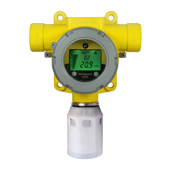
The Sensepoint XCD (“Exceed”) comprises a gas detector transmitter and a choice of sensors for detecting flammable gas, toxic gas and oxygen. The construction of Sensepoint XCD allows it to be used in hazardous area locations; it may also be used in other areas not classified as hazardous.
-
Page 7: Transmitter
Diagram 2: Sensepoint XCD Display and Magnetic Switches 4.2 Flammable, Toxic Oxygen Gas sensors The Sensepoint XCD transmitter is designed to work with a variety of gas sensors for detecting flammable gases. Sensepoint XCD sensors use NDIR infrared and electro- catalytic technologies.
-
Page 8: Accessories
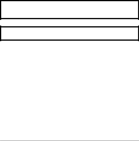
Diagram 3: Sensepoint XCD Flammable, Toxic and Oxygen Sensor Cartridge 4.3 Accessories A range of accessories are available to allow use of Sensepoint XCD in a wide variety of applications. These including mounting brackets, maintenance tools, weather housings, flow housing, collecting cone, duct mounting kit and sensor junction boxes.
-
Page 9
Sensepoint XCD Technical Manual SPXCDHMANEN Issue 2 Collecting cone Duct mounting kit The Duct Mounting Kit (P/N: SPXCDDMK) The Collecting Cone (P/N: SPXCDCC) is an is an optional accessory that is designed for optional accessory that may be fitted to the applications to allow the monitoring for the Weather Protection. -
Page 10: Installation
SPXCDHMANEN Issue 2 5 Installation WARNINGS Sensepoint XCD is designed for installation and use in Zone 1 or 2 hazardous areas in many countries including Europe and for Class 1 Division 1 or 2 area applications in North America. Installation must be in accordance with the recognized standards of the appropriate authority in the country concerned.
-
Page 11: Mounting And Location
5.2 Mounting the transmitter The Sensepoint XCD transmitter has an integral mounting plate consisting of four mounting holes on the transmitter body. The transmitter may be fixed directly to a surface mounting, or to a horizontal or vertical pipe/structure, 40.0-80.0mm (1.6 to 3.1 inches) in…
-
Page 12
SPXCDHMANEN Issue 2 Diagram 5: Mounting arrangements To mount the Sensepoint XCD transmitter to a Vertical or Horizontal pipe/structure, use the optional XCD Mounting Kit and following procedure: 1. Fit the four spring washers, then the plain washers to the M8 x 80mm SS316 bolts. -
Page 13: Installing The Sensor
Diagram 6: Installing the Sensor WARNINGS Care should be taken when removing and refitting the Sensepoint XCD plug-in Sensor to the Sensor Socket so that damage to the connection pins can be avoided. If using an anti-seize compound, the threads should be thinly coated with an approved silicone free compound e.g.
-
Page 14: Electrical Connections
Electrical connections WARNINGS Sensepoint XCD is designed for installation and use in Zone 1 or 2 hazardous areas in many countries including Europe and Class 1 Division 1 or 2 area applications in North America. Installation must be in accordance with the recognized standards of the appropriate authority in the country concerned.
-
Page 15: Transmitter Wiring
Caution: All electrical connections should be made in accordance with any relevant local or national legislation, standards or codes of practice. The Sensepoint XCD transmitter may be wired in either Current SOURCE or Current SINK configuration. These two options are offered to allow greater flexibility in the type of control system that it can be used with.
-
Page 16: Terminal Connections
Sensepoint XCD Technical Manual SPXCDHMANEN Issue 2 6.2 Terminal connections Note: Ensure that none of the wires in the terminal area cause an obstruction when refitting the Display Module. Ensure that the socket on the Display Module is fully engaged in the Display Module Connector on the Terminal Module.
-
Page 17: Power
SPXCDHMANEN Issue 2 6.3 Power The Sensepoint XCD transmitter requires a power supply from the controller of between 16Vdc and 32Vdc. Ensure that a minimum supply of 16Vdc is measured at the sensor, taking into account the voltage drop due to cable resistance.
-
Page 18: Cabling
Sensepoint XCD Technical Manual SPXCDHMANEN Issue 2 6.4 Cabling The use of industrial grade, suitably armoured field cable is recommended. For example, screened 3 cores (plus screen 90% coverage), suitably mechanically protected copper cable with a suitable M20 explosion-proof gland, or ¾” NPT steel conduit, with 0.5 to 2.5 mm2 (20 to 13 AWG) conductors.
-
Page 19: Ground Terminal Wiring
Sensepoint XCD Technical Manual SPXCDHMANEN Issue 2 The Earth Screen of the field cable should be “tied to Earth” or connected to Ground at one point only. It is common practise to adopt a STAR EARTH connection regime where all instrumentation Screens are connected at one common point.
-
Page 20: Default Configuration
Rising Flammable IR 100%LEL 20%LEL Rising 40%LEL Rising Flammable CAT 100%LEL 20%LEL Rising 40%LEL Rising Carbon Dioxide IR 2.00%Vol 0.40%Vol Rising 0.80%Vol Rising For details of how to change the configuration of the Sensepoint XCD please refer to section 13.
-
Page 21: Normal Operation
SPXCDHMANEN Issue 2 8 Normal Operation Sensepoint XCD is supplied configured and ready for use according to the “Default Settings” table shown above. However these setting may be tailored to a specific application requirement using the Sensepoint XCD configuration menu system.
-
Page 22: System Status
Sensepoint XCD Technical Manual SPXCDHMANEN Issue 2 8.2 System Status Display indications, current output and relay states for various operational conditions are shown in the following table. For further details of error messages and trouble shooting see section 12.3. System Status…
-
Page 23: Magnetic Wand Activation
Communication with the XCD is achieved by positioning the Magnetic Wand at one of three different positions on the front glass window of the Sensepoint XCD transmitter. Activation of the switches is verified by observing the Magnetic Wand Activation Icon on the LCD display…
-
Page 24: First Time Switch On (Commissioning)
Sensepoint XCD Technical Manual SPXCDHMANEN Issue 2 9 First time switch on (Commissioning) WARNING The following procedure requires the Transmitter Cover to be removed while carrying out supply voltage checks. Therefore the appropriate permits to work should be sought in preparation.
-
Page 25
Sensepoint XCD Technical Manual SPXCDHMANEN Issue 2 Note: For a full description of each screen shown in Diagram 15., please refer to Section 13.3 “Review Mode” of this Manual. Diagram 15: Normal Start up procedure (For the CO sensor version) 11.The warm up countdown of 60 seconds (depending on the gas type) is then… -
Page 26: Response Check And Calibration
SPXCDHMANEN Issue 2 10 Response Check and Calibration It is recommended to periodically carry out a gas response check on the Sensepoint XCD to ensure correct operation. This may be done in two ways; 1. A simple Response Check often referred to as a “BUMP TEST” is a test using calibration gas applied to the sensor via the nozzle of the Weather Protection or using the Sensepoint XCD Gassing Cap.
-
Page 27
Sensepoint XCD Technical Manual SPXCDHMANEN Issue 2 (ZERO CALIBRATION) 1. If the ambient air is NOT considered reliable to use to set the ZERO, then remove the weather protection and fit the Gassing Cap accessory (see Section 4.3) onto the sensor and apply a clean source of zero gas or compressed air. -
Page 28
12. The display will show the current gas reading, and the ‘ ’ icon flashes. 13. Connect the regulator to the span gas cylinder. 14. Apply the span gas to the sensor using the Sensepoint XCD Gassing Cap (see section 4.7 for description). The live gas reading is displayed. When the reading is ’… -
Page 29: Zeroing And Span Calibration Of Hydrogen Sulfide Sensors
Sensepoint XCD Technical Manual SPXCDHMANEN Issue 2 19. Promptly switch off the calibration span gas and remove the Sensepoint XCD Gassing Cap from the sensor to allow the gas to disperse. 20. When the reading falls below 50% of the calibration gas level the display indicates a countdown (up to 180 seconds dependant on gas type).
-
Page 30: General Maintenance
Access to the interior of the transmitter, when carrying out any work, must only be conducted by trained personnel. Care should be taken when removing and refitting the Sensepoint XCD plug-in Sensor Cartridge to the Sensor Socket so that damage to the connection pins can be avoided.
-
Page 31: Servicing
Do not expose sensor to organic solvents or flammable liquids. Care should be taken when removing and refitting the Sensepoint XCD plug-in Sensor Cartridge to the Sensor Socket so that damage to the connection pins can be avoided.
-
Page 32
Sensor Retainer Locking Grub Screw Diagram 13: Sensor Replacement To replace the plug-in sensor of a Sensepoint XCD Sensor Socket use the following procedure: 1. Important: Remove the Power from the Sensepoint XCD Transmitter 2. Remove the Weather Protection or other accessories from the sensor socket thread. -
Page 33: Replacing Modules Within The Transmitter
Sensepoint XCD Technical Manual SPXCDHMANEN Issue 2 12.2 Replacing Modules within the Transmitter Two replaceable module assemblies are located within the transmitter housing. The Display Module and the Terminal Module. The Display Module is simply removed by unplugging it from the Terminal Module (this procedure is done during normal installation).
-
Page 34: Faults And Warnings
Sensepoint XCD Technical Manual SPXCDHMANEN Issue 2 12.3 Faults and Warnings The table below provides details of possible error. Message Description Action The unit has not been calibrated for the configured calibration interval W-01 Calibration needed Calibration is necessary due to change…
-
Page 35: Menu’s And Advanced Configuration
Sensepoint XCD Technical Manual SPXCDHMANEN Issue 2 13 Menu’s and Advanced Configuration 13.1 Abort Function In Review Mode or Configuration Mode the user can escape one step back from the current position using the Abort Function. To do this the user must activate the Enter switch for more than 3 seconds with the Magnetic Wand.
-
Page 36
Sensepoint XCD Technical Manual SPXCDHMANEN Issue 2 Menu Display Description Execute zero/span calibration Set calibration gas level Set Calibration After zero, the option exists to proceed with span calibration, or return to the Menu. Select the type of sensor from the sensor list. -
Page 37
Sensepoint XCD Technical Manual SPXCDHMANEN Issue 2 Configure relay on delay time, relay off delay Relay Operation time and latch/non-latch Set location (or TAG number) Set Location Change temperature display unit. Set Temperature Unit °C (Celcius) or °F (Fahrenheit) Simulate alarm situation to check the alarm… -
Page 38: Configuration Mode Operation Table
Sensepoint XCD Technical Manual SPXCDHMANEN Issue 2…
-
Page 39
Sensepoint XCD Technical Manual SPXCDHMANEN Issue 2… -
Page 40: Sensor / Gas Selection
Sensepoint XCD Technical Manual SPXCDHMANEN Issue 2 13.3 Sensor / Gas Selection NOTE: This Configuration option is not available for XCD units with EC sensors 13.3.1 Sensor Selection “Select Sensor” sets the identity of the type of mV sensor attached to the XCD when XCD does not detect the sensor type automatically.
-
Page 41
Sensepoint XCD Technical Manual SPXCDHMANEN Issue 2 Sensor type Gas type Gas Name displayed Ir-1 Ir-3 Cb-1 Str1 to Str8 Gas selection is dependent on the type of sensor attached to the XCD. If Ir-1/Ir-3 sensor is attached, then a user can only select CO /mEt gas respectively. -
Page 42: Review Mode
Sensepoint XCD Technical Manual SPXCDHMANEN Issue 2 13.4 Review Mode The instrument will enter Review mode when the “Enter” switch is activated with the Magnetic Wand and held for around one second. Names, displays and descriptions for each review item in Review Mode are shown in the following table.
-
Page 43
Sensepoint XCD Technical Manual SPXCDHMANEN Issue 2 Location Location in which the transmitter is installed Power Power voltage* Temperature Internal Transmitter temperature* Peak conc. Maximum concentration detected up to now Test Result There is no fault detected. Table 8: Transmitter menu descriptions… -
Page 44
Sensepoint XCD Technical Manual SPXCDHMANEN Issue 2 Menu Switch (1s to 3s) Review Monitoring Mode Mode Abort Auto end to cycle S/W Version Test Result 2 second delay 2 second delay SRS Version Peak Reading 2 second delay 2 second delay… -
Page 45: General Specification
+/- 30% of applied gas from -20°C to -40°C (-4°F to -40°F) and +55°C to +65°C (+131°F to +149°F). Long term operation at this range may cause decline in sensor performance. Contact Honeywell Analytics for any additional data or details. Certification GB Ex d IIC T4 GB3836.1&2 -2000, PA, (CCCF –…
-
Page 46: Ordering Information
SPXCDHMANEN Issue 2 15 Ordering information Part Number Description Sensepoint XCD transmitter and sensor KIT (ATEX/IECEx/AP*, ADC12 and M20 Entry) SPXCDAAMFX ATEX/IECEx/AP* approved Methane CAT 0-100%LEL (20 to 100%LEL, 10%LEL) with ADC12, M20 Entry SPXCDAAMRX ATEX/IECEx/AP* approved Methane IR 0-100%LEL (20 to 100%LEL, 10%LEL) with ADC12, M20 Entry SPXCDAAMO1 ATEX/IECEx/AP* approved Oxygen 25.0%/Vol with ADC12, M20 Entry…
-
Page 47
Sensepoint XCD Technical Manual SPXCDHMANEN Issue 2 SPXCDUSNO1 UL approved Oxygen 25.0%/Vol with 316SS, 3/4″NPT Entry SPXCDUSNHX UL approved Hydrogen Sulfide 0-50ppm (10.0 to 100.0ppm, 1ppm) with 316SS, 3/4″NPT Entry SPXCDUSNCX UL approved Carbon Monoxide 0-300ppm (100 to 1000ppm, 100ppm) with 316SS, 3/4″NPT Entry SPXCDUSNG1 UL approved Hydrogen 0-1000ppm with 316SS, 3/4″NPT Entry… -
Page 48: Warranty Statement
Analytics reserves the right to charge for any site attendance where any fault is not found with he the equipment. Honeywell Analytics shall not be liable for any loss or damage whatsoever or howsoever occasioned which may be a direct or indirect result of the use or operation of the Contract Goods by the Buyer or any Party.
-
Page 49: Installation Drawing
Sensepoint XCD Technical Manual SPXCDHMANEN Issue 2 17 Installation Drawing 17.1 Mechanical Installation Drawing…
-
Page 50: Electronic Connection Drawing
Sensepoint XCD Technical Manual SPXCDHMANEN Issue 2 17.2 Electronic Connection Drawing…
-
Page 51: Duct Mounting Drawing
Sensepoint XCD Technical Manual SPXCDHMANEN Issue 2 17.3 Duct Mounting Drawing…
-
Page 52: Collecting Cone Drawing
Sensepoint XCD Technical Manual SPXCDHMANEN Issue 2 17.4 Collecting Cone Drawing…
-
Page 53: Mounting Bolt Assy Drawing
Sensepoint XCD Technical Manual SPXCDHMANEN Issue 2 17.5 Mounting Bolt Assy Drawing…
-
Page 54: Mounting Bracket Drawing
Sensepoint XCD Technical Manual SPXCDHMANEN Issue 2 17.6 Mounting Bracket Drawing…
-
Page 55: Certification
Sensepoint XCD Technical Manual SPXCDHMANEN Issue 2 18 Certification 18.1 China GB Ex and PA China GB Ex (Chinese Version):…
-
Page 56
Sensepoint XCD Technical Manual SPXCDHMANEN Issue 2 China GB Ex (English Version):… -
Page 57
Sensepoint XCD Technical Manual SPXCDHMANEN Issue 2 China PA Certification:… -
Page 58: Korea Ktl
Sensepoint XCD Technical Manual SPXCDHMANEN Issue 2 18.2 Korea KTL…
-
Page 59: European Atex
Sensepoint XCD Technical Manual SPXCDHMANEN Issue 2 18.3 European ATEX ATEX For Transmitter:…
-
Page 60
Sensepoint XCD Technical Manual SPXCDHMANEN Issue 2 ATEX for Sensor… -
Page 61: International Iec
Sensepoint XCD Technical Manual SPXCDHMANEN Issue 2 18.4 International IEC IEC Ex for Transmitter…
-
Page 62
Sensepoint XCD Technical Manual SPXCDHMANEN Issue 2 IEC Ex for Sensor… -
Page 63: Atex Name Plate
Sensepoint XCD Technical Manual SPXCDHMANEN Issue 2 18.5 Sensepoint XCD ATEX Name Plate…
-
Page 64: Ul Name Plate
Sensepoint XCD Technical Manual SPXCDHMANEN Issue 2 18.6 Sensepoint XCD UL Name Plate…
-
Page 65: Sensor Cartridges Label
Sensepoint XCD Technical Manual SPXCDHMANEN Issue 2 18.7 Sensor Cartridges Label…
-
Page 66: Cross Interference And Cross Calibration
19 Cross Interference and Cross Calibration 19.1 Cross Interference Table for Toxic and Oxygen This below table shows the relative cross sensitivity of the Sensepoint XCD to other gases. “Gas Type” indicated the XCD sensor type fitted to the XCD. “Gas Type Applied”…
-
Page 67: Cross Calibration Flammable Gas Detector
Therefore, it is possible to carry out a “cross calibration” using another hydrocarbon gas/air mixture. When the Sensepoint XCD Combustible LEL sensor is to be calibrated with a gas which is different to the gas or vapour to be detected, the following cross calibration procedure may…
-
Page 68
Sensepoint XCD Technical Manual SPXCDHMANEN Issue 2 Styrene Tetra hydrafuran Toluene Triethylamine Xylene Table 11 . Star Rating of Gases To cross calibrate the SG16B flammable gas detector catalytic bead: (1) Obtain the star rating for both the calibration test gas and the gas to be detected from… -
Page 69
62% LEL to give an accurate measuring scale for 0-100%LEL Ethylene, when using 50% LEL Methane as the calibration gas. Please contact your local Honeywell Analytics sales or service distributor, or regional office should further clarification or additional information be required. -
Page 70
Tel: +1 847 955 8200 Toll free: +1 800 538 0363 Fax: +1 847 955 8208 detectgas@honeywell.com Asia Pacific Honeywell Analytics Asia Pacific Please Note: #508, Kolon Science Valley (I) While every effort has been made to ensure accuracy in this publication, no responsibility 187-10 Guro-Dong, Guro-Gu can be accepted for errors or omissions.
![]()
Technical Handbook
Sensepoint XCD RFD
(Remote Flammable Detector)

|
Sensepoint XCD RFD Technical Manual |
SPXCDHMRFEN Issue 4_08-2016 |
1 Safety
Ensure that this Operating Manual is read and understood BEFORE installing / operating / maintaining the equipment. Pay particular attention to Warnings and Cautions. All document Warnings are listed here and repeated where appropriate at the start of the relevant chapter(s) of this Operating Manual. Cautions appear in the sections/sub-sections of the document where they apply
WARNINGS
Sensepoint XCD RFD is designed for installation and use in Zone 1 or 2 hazardous areas in many countries including Europe, and for Class I, Division 1, Groups B, C & D Hazardous Areas in the Americas.
Installation must be in accordance with the recognized standards of the appropriate authority in the country concerned.
Access to the interior of the detector, when carrying out any work, must only be conducted by trained personnel.
Before carrying out any work ensure local regulations and site procedures are followed.
Appropriate standards must be followed to maintain the overall certiication of the detector.
If using an anti-seize compound, the threads should be thinly coated with an approved silicone free compound e.g. petroleum jelly
To reduce the risk of ignition of hazardous atmosphere, de-classify the area or disconnect the equipment from the supply circuit before opening the detector enclosure. Keep assembly tightly closed during operation.
Never attempt to open a junction box/enclosure or replace/reit the sensor in potentially hazardous atmospheres while power is still applied to the transmitter.
The detector must be earthed/grounded for electrical safety and to limit the effects of radio frequency interference. Earth/ground points are provided inside and outside the unit. The internal grounding shall be used as the primary equipment ground. The external terminal is only a supplemental bonding connection where local authorities permit or require such a connection.
Ensure that all screens/instrument earth/clean earth wiring is earthed/grounded at a single point (either at the controller or detector — BUT NOT BOTH) to prevent false readings or alarms that may occur due to potential earth/ground loops.
Take care when handling sensors as they may contain corrosive solutions. Do not tamper with or in any way disassemble the sensor.
Do not expose to temperatures outside the recommended ranges.
Do not expose sensors under storage conditions to organic solvents or lammable liquids.
Refer to the local or national regulations relative to the installation at the site. For Europe see EN60079-29-2, EN60079-14 and EN61241-14.
Only assessed for ATEX for ignition hazards.
This equipment is designed and constructed as to prevent ignition sources arising, even in the event of frequent disturbances or equipment operating faults. Note: The control card must have a suitably rated fuse.
The sensor head must be itted with the supplied weather protection, and mounted so that the sinter is pointing downward to provide ingress protection IPX6.
The weather protection is a potential electrostatic charging hazard. The manufacturer’s instructions should be observed.
For Safety reasons, this equipment must be operated and serviced by qualified personnel only
(Pour des raisons de securite, Cet equipment doit etre utilise,
Entretenu et repare uniquement par un personnel qualifie) EMI signal may cause incorrect operations.
Any rapid upscale reading followed by a declining or erratic reading may indicate a gas concentration beyond the upper scale limit which may be hazardous.
2
|
Sensepoint XCD RFD Technical Manual |
SPXCDHMRFEN Issue 4_08-2016 |
2 Information
This manual is for use with the Sensepoint XCD RFD range transmitters only.
The Start-up/Surge/In rush current is dependant on the type of power supply used. The typical start-up current for Sensepoint XCD RFD is less than 800mA. Measure the startup current using the specific power supply before installation to ensure suitability for your application.
Honeywell Analytics can take no responsibility for installation and/or use of its equipment if not done so in accordance with the appropriate issue and/or amendment of the Technical Manual.
The reader of this Operating Manual should ensure that it is appropriate in all details for the exact equipment to be installed and/or operated. If in doubt, contact Honeywell Analytics for advice.
The following types of notices are used throughout this Operating Manual:
WARNING
Identifies a hazardous or unsafe practice which could result in severe injury or death to personnel.
Caution: Identifies a hazardous or unsafe practice which could result in minor injury to personnel, or product or property damage.
Note: Identifies useful/additional information.
Every effort has been made to ensure the accuracy of this document; however, Honeywell Analytics can assume no responsibility for any errors or omissions in this document or their consequences.
Honeywell Analytics would greatly appreciate being informed of any errors or omissions that may be found in the content of this document.
For information not covered in this document, or if there is a requirement to send comments/corrections about this document, please contact Honeywell Analytics using the contact details given on the back page.
Honeywell Analytics reserve the right to change or revise the information supplied in this document without notice and without obligation to notify any person or organization of such revision or change. If information is required that does not appear in this document, contact the local distributor/agent or Honeywell Analytics.
3

|
Sensepoint XCD RFD Technical Manual |
SPXCDHMRFEN Issue 4_08-2016 |
|
3 Table of contents |
|
|
1 Safety……………………………………………………………………………………………………………….. |
2 |
|
2 Information……………………………………………………………………………………………………….. |
3 |
|
4 Introduction………………………………………………………………………………………………………. |
6 |
|
4.1 Transmitter…………………………………………………………………………………………………… |
7 |
|
4.2 Flammable Gas sensors………………………………………………………………………………… |
7 |
|
4.2.1 Sensepoint XCD flammable gas sensors ……………………………………………………… |
8 |
|
4.2.2 Sensepoint LEL Flammable gas sensors ……………………………………………………… |
8 |
|
4.2.3 705 LEL flammable gas sensors (UL approved)……………………………………………… |
9 |
|
4.3 Accessories………………………………………………………………………………………………….. |
9 |
|
4.4 Options ……………………………………………………………………………………………………… |
11 |
|
4.4.1 Modbus® …………………………………………………………………………………………………. |
11 |
|
5 Installation………………………………………………………………………………………………………. |
13 |
|
5.1 Mounting and location………………………………………………………………………………….. |
14 |
|
5.2 Mounting the transmitter ………………………………………………………………………………. |
14 |
|
5.3 Installing the sensor…………………………………………………………………………………….. |
15 |
|
6 Electrical connections ……………………………………………………………………………………. |
17 |
|
6.1 Transmitter Wiring……………………………………………………………………………………….. |
18 |
|
6.2 Terminal connections …………………………………………………………………………………… |
19 |
|
6.3 Power………………………………………………………………………………………………………… |
20 |
|
6.4 Cabling………………………………………………………………………………………………………. |
21 |
|
6.5 Cable and Earth/Ground regimes ………………………………………………………………….. |
21 |
|
6.6 Ground Terminal Wiring ……………………………………………………………………………….. |
22 |
|
7 Default configuration ………………………………………………………………………………………. |
23 |
|
8 Normal Operation ……………………………………………………………………………………………. |
24 |
|
8.1 Display Screen……………………………………………………………………………………………. |
24 |
|
8.2 System Status…………………………………………………………………………………………….. |
25 |
|
8.3 Magnetic Wand Activation…………………………………………………………………………….. |
26 |
|
8.4 Operation Mode Structure ……………………………………………………………………………. |
26 |
|
9 First time switch on (Commissioning) ……………………………………………………………… |
27 |
|
10 Response Check and Calibration …………………………………………………………………… |
29 |
|
10.1 Zeroing and span calibration ……………………………………………………………………… |
29 |
|
11 General Maintenance……………………………………………………………………………………… |
33 |
|
11.1 Operational Life…………………………………………………………………………………………. |
33 |
|
12 Servicing ………………………………………………………………………………………………………. |
34 |
|
12.1 Sensor replacement…………………………………………………………………………………… |
34 |
|
12.2 Replacing Modules within the Transmitter …………………………………………………….. |
36 |
|
12.3 Faults and Warnings………………………………………………………………………………….. |
37 |
|
13 Menu’s and Advanced Configuration……………………………………………………………… |
38 |
|
13.1 Abort Function…………………………………………………………………………………………… |
38 |
|
13.2 Configuration Mode …………………………………………………………………………………… |
38 |
|
13.3 Sensor / Gas Selection ………………………………………………………………………………. |
44 |
|
13.4 Review Mode ……………………………………………………………………………………………. |
46 |
|
14 General specification…………………………………………………………………………………….. |
49 |
4

|
Sensepoint XCD RFD Technical Manual |
SPXCDHMRFEN Issue 4_08-2016 |
||
|
15 Ordering information…………………………………………………………………………………….. |
50 |
||
|
16 Warranty statement ………………………………………………………………………………………. |
52 |
||
|
17 Installation Drawing ……………………………………………………………………………………… |
53 |
||
|
17.1 |
Mechanical Installation Drawing ………………………………………………………………… |
53 |
|
|
17.2 |
Electronic Connection Drawing…………………………………………………………………… |
54 |
|
|
17.3 |
Duct Mounting Drawing …………………………………………………………………………….. |
56 |
|
|
17.4 |
Collecting Cone Drawing …………………………………………………………………………… |
57 |
|
|
17.5 |
Mounting Bolt Assy Drawing ………………………………………………………………………. |
58 |
|
|
17.6 |
Mounting Bracket Drawing…………………………………………………………………………. |
55 |
|
|
17.7 |
Sensepoint XCD RFD Sensor ……………………………………………………………………. |
59 |
|
|
17.8 |
Control Drawing ……………………………………………………………………………………….. |
61 |
|
|
18 Certification………………………………………………………………………………………………….. |
63 |
||
|
18.1 China GB Ex and PA…………………………………………………………………………………. |
63 |
||
|
18.2 |
Korea KTL……………………………………………………………………………………………….. |
66 |
|
|
18.3 |
European ATEX ……………………………………………………………………………………….. |
67 |
|
|
18.4 |
International IEC ………………………………………………………………………………………. |
69 |
|
|
18.5 |
Sensepoint XCD ATEX Name Plate ……………………………………………………………. |
71 |
|
|
18.6 |
Sensor Cartridges Label ……………………………………………………………………………. |
72 |
|
|
19 Cross Interference and Cross Calibration ……………………………………………………… |
73 |
||
|
19.1 |
Cross Calibration Flammable Gas Detector …………………………………………………. |
73 |
|
|
19.2 Meter Multiplication Factors for Sensepoint XCD-IR Propane…………………………. |
76 |
||
|
19.2 Meter Multiplication Factors for Sensepoint XCD-IR Propane…………………………. |
76 |
||
|
A.1 Modbus® and the XCD …………………………………………………………………………………. |
77 |
||
|
A.2 Modbus® Registers ……………………………………………………………………………………… |
78 |
5

|
Sensepoint XCD RFD Technical Manual |
SPXCDHMRFEN Issue 4_08-2016 |
4 Introduction
The Sensepoint XCD RFD (“Exceed RFD”) transmitter allows the user to either directly or remotely mount a flammable gas sensor from the Sensepoint XCD , Sensepoint and
705 sensor ranges. The remote sensor can be located up to 30 meters (100 feet) from the transmitter. The transmitter features a display and three programmable relays for controlling external equipment e.g. alarms, sirens, valves or switches. The transmitter provides an industry standard 3-wire, 4-20mA source or sink output for connection to a dedicated gas detection control system or PLC.
The construction of Sensepoint XCD RFD allows it to be used in hazardous area locations; it may also be used in other areas not classified as hazardous. Sensepoint XCD RFD is suitable for use in Zone 1 or 2 hazardous areas (International).
Calibration and maintenance is carried out using a Magnetic Wand, this allows a single user to undertake routine maintenance without needing to access internal components.
Sensepoint XCD RFD comprises of the main parts as shown below.
M20 or 3/4″NPT cable/conduit entries
|
Display Module |
(x2) |
Certification Label |
|
Integral |
||
|
Ex d Plug |
||
|
mounting plate |
||
|
Cover |
|
Internal Earth |
||||
|
Point |
||||
|
Terminal Module |
External Earth |
|||
|
Locking |
Seal |
Point (x2) |
||
|
Grub |
Enclosure |
|||
|
screw |
M25 or 3/4″NPT entry for
Flammable Sensor or Remote Sensor Cable Gland
Diagram 1. – Exploded View
6

|
Sensepoint XCD RFD Technical Manual |
SPXCDHMRFEN Issue 4_08-2016 |
4.1 Transmitter
The transmitter enclosure has three threaded entries. The two cable entries either side of the upper part of the transmitter housing are for connecting the power source, signal output and relay contacts to associated signalling equipment. The bottom entry allows local (direct) mounting of the appropriate sensor, or cable entry when using a remotely mounted sensor. These three entries are ¾” NPT for the Americas. For Europe and most other regions of the world, the two cable entries are provided with an M20 thread and the bottom entry is M25 for the sensor.
A local LCD provides gas type, concentration, alarm and operating status. The display provides numerical, bar graph and icon information.
Diagnostic information may also be displayed when the transmitter is interrogated using a magnet. The transmitter cover has a glass window which allows use of the Magnetic Wand to activate the three user interface magnetic switches that are located on the front of the display module. The magnet also enables a non intrusive, one-man calibration and configuration facility for the Sensepoint XCD RFD.
Magnetic
MENU/ENTER
Switch
Full Scale
Bar Graph
Gas Type
Gas Reading
Magnetic
DOWN
Switch
Magnetic Wand
activation Icon
Calibration Icon
Test Pass Icon
Warning/
Fault Icon
Inhibit Icon
Alarm Icon
Measuring
Units
|
Magnetic |
||
|
XCD RFD |
||
|
UP Switch |
||
Diagram 2: Sensepoint XCD RFD Display and Magnetic Switches
4.2 Flammable Gas sensors
Sensepoint XCD RFD is designed to work with the flammable sensors from the Sensepoint XCD, 705 and Sensepoint sensor ranges. Sensepoint XCD sensors use NDIR infrared and electro-catalytic technologies. The Sensepoint XCD range is ATEX approved for use throughout Europe and many parts of the world.
Please refer to chapter 15 ‘Ordering information’ for more detail information.
7
|
Sensepoint XCD RFD Technical Manual |
SPXCDHMRFEN Issue 4_08-2016 |
4.2.1 Sensepoint XCD flammable gas sensors
Sensepoint XCD flammable gas sensors are ATEX approved for use in Zone 1 or 2 hazardous areas. Two versions are available: IR and CAT versions. For more sensor specific details, refer to the Quick Start Guide of Sensepoint XCD Remote Flammable Sensor (PN: 3001M5022_1). These sensors are not approved for use in the Americas or Canada.
Diagram 3: Sensepoint XCD Flammable Sensor and Plug-in Cartridge
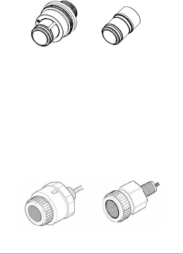
4.2.2 Sensepoint LEL Flammable gas sensors
Standard LEL Version
The standard LEL sensor is available for use in temperatures up to 80°C (remote mounting only) and detects gas concentrations up to 100% LEL of a target gas with a resolution in the region of 1% LEL, depending on the gas being detected. The sensor is available with M25 thread. M20 or ¾” NPT threads are options.
High temperature LEL Version
The high temperature version is available for use in temperatures up to 150°C (remote mounting only) and ranges of 0-20%LEL or 0-100%LEL depending on transmitter or controller. The sensor is available with M25 thread. M20 or ¾” NPT threads are options.
Details of connecting these sensors with the Sensepoint XCD RFD transmitter are given in sections 5 and 6. For more sensor specific details, refer to the Technical Handbook Part
No. 2106M0502 or their individual manuals (Sensepoint HT Sensor Quick Start Guide Part No: 2106M0523, Sensepoint LEL Operating Instructions Part No: 2106M0501). These sensor are not approved for use in the Americas or Canada.
|
Standard LEL version |
High Temperature LEL version |
Diagram 4: Sensepoint LEL flammable sensors
8

|
Sensepoint XCD RFD Technical Manual |
SPXCDHMRFEN Issue 4_08-2016 |
4.2.3. 705 LEL Flammable gas sensors (UL Approved)
Standard LEL version
The standard LEL sensor is available for use in temperatures up to 80°C (remote mounting only) and detects gas concentrations up to 100% LEL of a target gas with a resolution in the region of 1% LEL, depending on the gas being detected. The sensor is available with ¾”NPT thread only.
High Temperature LEL version
The high temperature version is available for use in temperatures up to 150°C (remote mounting only) and detects gas concentrations up to 100% LEL of a target gas with a resolution in the region of 1% LEL, depending on the gas being detected. The sensor is available with ¾”NPT thread only.
Details of connecting these sensors with the Sensepoint XCD RFD transmitter are given in sections 5 and 6. For more sensor specific details, refer to the 705 Combustible Gas
Sensor Operating Instructions Part No: 00705M5002.
|
Standard LEL version |
High Temperature LEL version |
705 LEL flammable sensors
9
|
Sensepoint XCD RFD Technical Manual |
SPXCDHMRFEN Issue 4_08-2016 |
4.3 Accessories
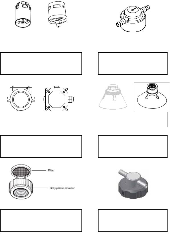
A range of accessories are available to allow use of Sensepoint XCD RFD in a wide variety of applications. These include Pipe mounting bracket, Sunshade deluge cover, Sensor collecting cone, Sensor flow Housing and Remote sensor mounting junction boxes.
|
For Sensepoint XCD |
For Sensepoint / 705 |
|
(P/N: SPXCDWP) |
(P/N: 02000-A-1640/1635) |
Standard Weather Protection
The Standard Weather Protection is designed to protect the sensor from changes in environmental conditions. This is recommended to be fitted to a Sensepoint XCD sensor and Sensepoint / 705 sensors.
|
For UL/CSA Junction Box |
For ATEX Junction Box |
|
(P/N: 2430-0021) |
(P/N: 00780-A-0100) |
Remote Sensor Mounting
UL aluminum junction box,ATEX standard junction box and
ATEX High temperature junction box (P/N: 2052D0001) are optional accessories that can be used for remote sensor mounting. Make the connection from the junction box to the transmitter using suitable cable and cable glands.
Sensepoint Filter and Filter Housing
Sensepoint Stainless steel filter (P/N: 00780-
F-0018) and Filter Housing (P/N: 00780-C-
0038) is an optional accessory can be used to offer additional protection to the Sinter in dry, and dusty applications.
Calibration Cup
The Gassing Cap (P/N: S3KCAL) is an optional accessory that may be temporarily fitted to
Sensepoint XCD flammable sensors for Gas
Response checking during commissioning and routine maintenance.
|
For Sensepoint XCD |
For Sensepoint / 705 |
|
(P/N: SPXCDCC) |
(P/N: 02000-A-1642) |
Collecting Cone
The Collecting Cone is an optional accessory that may be fitted to the Weather Protection of XCD and Sensepoint / 705 sensors.
The collecting cone is designed for use with gases that are lighter than air.
Calibration Gas Flow Housing
The Calibration Gas Flow Housing (P/N: 02000-
A-1645) may be used for either calibration of the
Sensepoint / 705 sensor or if the Sensepoint / 705 sensor is to be used as part of a Aspirated Sampling System.
10
![]()
|
Sensepoint XCD RFD Technical Manual |
SPXCDHMRFEN Issue 4_08-2016 |
4.4 Options
4.4.1 Modbus®
One of the most common field buses in the industry, the optional Modbus® interface allows the XCD to connect to a bus of devices and transmit data to PLCs or controllers (see Appendix A). Connections to the XCD are made through a pluggable terminal block on the Modbus® interface circuit board. Modbus® RTU protocol uses ASCII/Hex protocols for communication. And allows all transmitter/sensor front panel functions to be transmitted using this industrial fieldbus.
Modbus® protocol is a Master-Slaves protocol. Only one master (at the same time) is connected to the bus and one or up to 32 slave nodes are also connected to the same serial bus. Modbus® communication is always initiated by the master. The slave nodes will never transmit data without receiving a request from the master node. The slave nodes will never communicate with each other. The master node initiates only one Modbus® transaction at the same time.
The MODBUS® may only be used for data collection or record keeping with regard to combustible gas detection and not for performance verification.
Modbus® option is available only for selected gases. Please refer to chapter 15 Ordering information.
To find out if a unit has the Modbus® option fitted, look at the part number on the product label. Units fitted with Modbus® have the letter “M” at the end of the part number.
Note: MODBUS® is a registered trademark of Schneider Automation Inc.
11

|
Sensepoint XCD RFD Technical Manual |
SPXCDHMRFEN Issue 4_08-2016 |
(MODBUS ID SETTING)
Set id>>Set Modbus slave ID>>Set Baud rate>>Set Parity
1)Slave ID shall be set 1~247
2)Baud rate setting 9600 or 19200
3)Parity setting (No, Even, Odd)
From the Configuration Mode screen, select‘’. To set the Modbus Slave ID, use the up-down ‘’switches to move to the desired position and use ‘’to select it. Again, using the‘’switches, increment or decrement the value until the desired value appears, selects the value and moves to the next setting.
The communications baud rate and Parity Setting can also be set from this screen by using the‘’ switches to navigate to the baud rate display then selecting ‘’. Using the
‘’switches, highlight the proper baud rate or parity setting and select‘’. Default is Slave ID 1, 19200bps and even parity.
Note: Set ID menu is available only for XCD equipped with Modbus® option.
12

|
Sensepoint XCD RFD Technical Manual |
SPXCDHMRFEN Issue 4_08-2016 |
5 Installation
Refer to the Sensepoint XCD RFD Control Drawing 3001EC091 for CSA applications shown in section 17.
WARNINGS
Sensepoint XCD RFD is designed for installation and use in Zone 1 or 2 hazardous areas in many countries including Europe, and for Class I, Division 1, Group B,C & D Hazardous Areas in the Americas.
Installation must be in accordance with the recognized standards of the appropriate authority in the country concerned.
Access to the interior of the detector, when carrying out any work, must only be conducted by trained personnel.
Before carrying out any work ensure local regulations and site procedures are followed.
Appropriate standards must be followed to maintain the overallcertification of the detector.
Care should be taken when removing and refitting the SensepointXCD plug-in Sensor to the
Sensor Socket so that damage to the connection pins can be avoided.
If using an anti-seize compound, the threads should be thinly coated with an approved silicone free compound e.g. petroleum jelly
To reduce the risk of ignition of hazardous atmosphere, de-classify the area or disconnect the equipment from the supply circuit before opening the detector enclosure. Keep assembly tightly closed during operation.
Never attempt to open a junction box/enclosure or replace/refitthe sensor in potentially hazardous atmospheres while power is still applied to the transmitter.
The detector must be earthed/grounded for electrical safety and to limit the effects of radio frequency interference. Earth/ground points are provided inside and outside the unit. Ensure that all screens/instrument earth/clean earth wiring is earthed/grounded at a single point (either at the controller or detector — BUT NOT BOTH) to prevent false alarms due to earth/ ground loops.
Take care when handling sensors as they may contain corrosive solutions. Do not tamper with or in any way disassemble the sensor.
Do not expose to temperatures outside the recommended ranges.
Do not expose sensors under storage conditions to organic solvents or flammable liquids.
Refer to the local or national regulations relative to the installation at the site. For Europe see EN60079-29-2, EN60079-14 and EN61241-14.
Only assessed for ATEX for ignition hazards.
This equipment is designed and constructed as to prevent ignition sources arising, even in the event of frequent disturbances or equipment operating faults. Note: The control card must have a suitably rated fuse.
The sensor head must be fitted with the supplied weather protection, and mounted so that the sinter is pointing downward to provide ingress protection IPX6.
The weather protection is a potential electrostatic charging hazard. The manufacturer’s instructions should be observed.
The Sensepoint sensor is a possible Electrostatic risk — Do not rub or clean with solvents.
Clean with a damp cloth. High velocity airflows and dusty environments can cause hazardous electrostatic charges.
13

|
Sensepoint XCD RFD Technical Manual |
SPXCDHMRFEN Issue 4_08-2016 |
5.1 Mounting and location
Caution: The location of gas detectors should be made in accordance with any relevant local and national legislation, standards or codes of practice. Always replace sensors with a sensor of the same type.
Gas detectors should be mounted where a potential hazard of gas is most likely to be present. The following points should be noted when locating gas sensors.
•When locating detectors consider the possible damage caused by natural events e.g. rain or flooding.
•Consider ease of access to the gas detector for functional testing and servicing.
•Consider how escaping gas may behave due to natural or forced air currents.
Note: The placement of gas detectors should be determined following the advice of experts having specialist knowledge of gas dispersion, experts having knowledge of the process plant system and equipment involved, safety and engineering personnel. The agreement reached on the location of detectors should be recorded.
5.2 Mounting the transmitter
The Sensepoint XCD RFD transmitter has an integral mounting plate consisting of four mounting holes on the transmitter body. The transmitter may be fixed directly to a surface mounting, or to a horizontal or vertical pipe/structure, 40.0-80.0mm (1.6 to 3.1 inches) in diameter/cross section. The Pipe Mounting Bracket accessory (optional accessory) may be used for this purpose.
M20 or 3/4 NPT entries
All dimensions are shown in mm.
Diagram 5: Outline and mounting dimensions
14

|
Sensepoint XCD RFD Technical Manual |
SPXCDHMRFEN Issue 4_08-2016 |
5.3 Installing the sensor
WARNINGS
Care should be taken when removing and refitting the SensepointXCD plug-in Sensor to the Sensor Socket so that damage to the connection pins can be avoided.
If using an anti-seize compound, the threads should be thinly coated with an approved silicone free compound e.g. petroleum jelly
Take care when handling old sensors as they may contain corrosive solutions.
Take care when removing or replacing the Sensor Retainer as there may be sharp edges present on the adjoining threads.
The equipment is designed and constructed as to prevent ignition sources arising, even in the event of frequent disturbances or equipment operating faults.
Only assessed for ATEX for ignition hazards.
The sensor head must be fitted with the supplied weather protection, and mounted so that the sinter is pointing downward to provide ingress protection IPX6.
The weather protection is a potential electrostatic charging hazard. The manufacturer’s instructions should be observed.
A remotely mounted sensor should be mounted using a suitable junction box . For further details regarding mounting sensors to suitable junction boxes refer to the relevant sensor manual.
1.Connect the remote sensor/junction box to the Sensepoint XCD RFD transmitter using suitable cable with wires of diameter 0.5 — 2.5mm2 (20AWG — 13AWG).
2.Connect the cable to the transmitter enclosure via the bottom entry.
3.Cable (non conduit) based installations must use appropriately certified cable glands.
Refer to the Sensepoint XCD RFD Control Drawing 3001EC091 shown in section 17 for conduit based installation in the Americas.
Note: The maximum cable length between the remotely mounted sensor and the Sensepoint XCD RFD transmitter is 30 meters (100 feet). The maximum loop resistance is 17 Ω.
4.Terminate the wires from the sensor in the transmitter as shown in chapter 6.2.
5.Select sensor type at configuration menu after remote sensor mounting. Refer to the chapter 12.1 Sensor Replacement and the chapter 13.3.1 Sensor Selection.
Sensepoint XCD RFD with Sensepoint Remote Sensor
15

|
Sensepoint XCD RFD Technical Manual |
SPXCDHMRFEN Issue 4_08-2016 |
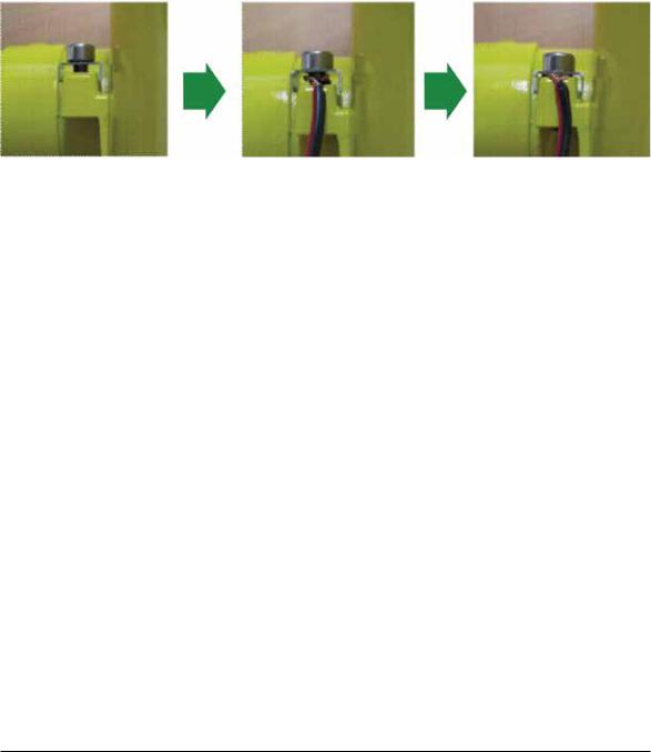
Sensepoint XCD RFD with Sensepoint XCD remote plug-in sensor
It is necessary to use a ferrite filter at the remote sensor to reduce electromagnetic interference. The ferrite filter (supplied) should be fitted as follows:
1.Screw the sensor into the remote junction box.
2.Open the ferrite filter.
3.Wind the sensor leads 2 turns round the ferrite filter.
4.Close the ferrite filter.
5.Follow instructions in the individual sensor manuals to complete installation.
16

|
Sensepoint XCD RFD Technical Manual |
SPXCDHMRFEN Issue 4_08-2016 |
6 Electrical connections
WARNINGS
Sensepoint XCD RFD is designed for installation and use in Zone 1 or 2 hazardous areas in many countries including Europe, and for Class I, Division 1, Group B,C & D Hazardous Areas in the Americas.
Installation must be in accordance with the recognized standards of the appropriate authority in the country concerned.
Access to the interior of the detector, when carrying out any work, must only be conducted by trained personnel.
Before carrying out any work ensure local regulations and site procedures are followed.
Appropriate standards must be followed to maintain the overallcertification of the detector.
Care should be taken when removing and refitting the SensepointXCD Sensor Cartridge to the Sensor Socket so that damage to the connection pins can be avoided.
If using an anti-seize compound, the threads should be thinly coated with an approved silicone free compound e.g. petroleum jelly
To reduce the risk of ignition of hazardous atmosphere, de-classify the area or disconnect the equipment from the supply circuit before opening the detector enclosure. Keep assembly tightly closed during operation.
Never attempt to open a junction box/enclosure or replace/refitthe sensor in potentially hazardous atmospheres while power is still applied to the transmitter.
The detector must be earthed/grounded for electrical safety and to limit the effects of radio frequency interference. Earth/ground points are provided inside and outside the unit. Ensure that all screens/instrument earth/clean earth wiring is earthed/grounded at a single point (either at the controller or detector — BUT NOT BOTH) to prevent false alarms due to earth/ground loops.
Take care when handling sensors as they may contain corrosive solutions. Do not tamper with or in any way disassemble the sensor.
Do not expose to temperatures outside the recommended ranges.
Do not expose sensors under storage conditions to organic solvents or flammable liquids.
Refer to the local or national regulations relative to the installation at the site. For Europe see EN60079-29-2, EN60079-14 and EN61241-14. For the Americas refer to the Sensepoint XCD RTD Control Drawing 3001EC091 shown in section 17.
17

|
Sensepoint XCD RFD Technical Manual |
SPXCDHMRFEN Issue 4_08-2016 |
6.1 Transmitter Wiring
Caution: All electrical connections should be made in accordance with any relevant local or national legislation, standards or codes of practice.
The Sensepoint XCD RFD transmitter may be wired in either Current SOURCE or Current SINK configuration. These two options are offered to allow greater flexibility in the type of control system that it can be used with. SOURCE/SINK is selectable via the switch located on the back side of the display module; accessible by removing the display module during installation / commissioning (see section 9).
|
Controller |
Detector |
||
|
+VE |
1 |
1 |
+VE |
|
Signal |
2 |
3 |
Signal |
|
RL |
|||
|
-VE |
3 |
2 |
-VE |
|
XCD Source 3 Wire 4-20mA (Source) |
|||
|
Controller |
Detector |
||
|
+VE |
1 |
1 |
+VE |
|
RL |
|||
|
Signal |
2 |
3 |
Signal |
|
-VE |
3 |
2 |
-VE |
XCD Sink 3 Wire 4-20mA (Sink)
Note: Terminate cable screen at detector or controller, not both.
Caution: 250ohm load resistor (RL) is installed in the factory, In case of connection with controller, this resistor should be removed because controller has load resistor internally.
18

Sensepoint XCD RFD Technical Manual SPXCDHMRFEN Issue 4_08-2016
6.2 Terminal connections
Note: Ensure that none of the wires in the terminal area cause an obstruction when refitting the Display Module. Ensure that the socket on the Display Module is fully engaged in the Display Module Connector on the Terminal Module. 
|
Ground/Earth |
||||
|
Point |
||||
|
Terminal Block |
Terminal Block |
|||
|
Power & Signal |
for Relays |
|||
|
Display Module |
Display Module |
|||
|
Alignment Pin |
||||
|
Connector |
||||
|
Locator |
||||
|
Note: Terminal |
||||
|
Terminal block for |
Blocks are |
|||
|
plug/socket type |
||||
|
Sensepoint or 705 |
||||
|
and may be |
||||
|
Flammable sensor |
removed to ease |
|||
|
wiring. |
||||
|
Diagram 6: Sensepoint XCD RFD Terminal module |
||||
|
Terminal |
Terminal Module Connections |
|||
|
Marking |
Connection |
Description |
||
|
Number |
||||
|
1 |
24V |
+VE Supply(12-32VDC) |
||
|
2 |
0V |
-VE Supply(0VDC) |
Controller Connections |
|
|
3 |
4~20mA |
Current Output Signal |
||
|
4 |
COM |
Common |
MODBUS RTU. RS485 |
|
|
5 |
TxD |
MODBUS A(+) |
||
|
(Optional) |
||||
|
6 |
RxD |
MODBUS A(-) |
||
|
7 |
RLY1/NC |
Normally Closed |
Programmable Relay 1 |
|
|
8 |
RLY1/COM |
Common |
||
|
(Default A1) |
||||
|
9 |
RLY1/NO |
Normally Open |
||
|
10 |
RLY2/NC |
Normally Closed |
Programmable Relay 2 |
|
|
11 |
RLY2/COM |
Common |
||
|
(Default A2) |
||||
|
12 |
RLY2/NO |
Normally Open |
||
|
13 |
RLY3/NC |
Normally Closed |
Programmable Relay 3 |
|
|
14 |
RLY3/COM |
Common |
||
|
(Default Fault) |
||||
|
15 |
RLY3/NO |
Normally Open |
||
|
16 |
+VE |
Sensitive (Sensor Brown Wire) |
||
|
17 |
-VE |
Non-Sensitive (Sensor Blue Wire) |
RFD Sensor Connection |
|
|
18 |
01 |
Signal (Sensor White Wire) |
Table 1: Transmitter terminal connections
Note: The Sensepoint HT sensor and 705 HT sensor (not covered by the CSA certification) must be earthed either at the remote junction box or at the transmitter as appropriate. Avoid earth loops.
19

|
Sensepoint XCD RFD Technical Manual |
SPXCDHMRFEN Issue 4_08-2016 |
6.3 Power for UL/CSA Version
The Sensepoint XCD transmitter(UL/CSA versions)requires a power supply from the controller of between 12Vdc and 32Vdc. Ensure that a minimum supply of 12Vdc is measured at the sensor, taking into account the voltage drop due to cable resistance.
The maximum loop resistance in the field cable is calculated as follows
R loop = (V controller – V detector min) / I detector
Example;
The controller is supplying a nominal 24Vdc (V controller), the detector minimum allowable
voltage is 12Vdc (V detector min), therefore the maximum allowable voltage drop between the controller and detector is 12Vdc; this means a voltage drop of 6V in each core (+ve core
and -ve core).
|
+18V |
+24V |
|
(wrt Controller 0V) |
|
12V (min) |
4-20mA |
Signal |
|
XCD |
Controller |
|
|
Field Cable (L) |
||
|
+6V |
0V |
|
(wrt Controller 0V) |
Diagram 7: Power Connection |
Power consumption of the detector is 5.0W. The current required to drive the detector at the minimum voltage is (I = P / V), 5.0 / 12 = 416.7 mA (I detector).
So, the maximum ieldcable loop resistance (R loop) = 12 / 0.42 = 28.8 Ohms, or 14.4 Ohms per core, (allowing for component variations, losses, etc.).
The following tables show the maximum cable distances between the controller and transmitter assuming a voltage drop of 4V in each core and for different cable parameters. The tables are examples only and actual cable parameters and source power supply voltage for the application should be used to calculate the maximum cable distance allowed at the installation site.
|
Typical cable data |
Maximum Cable length (L) |
|||
|
Cable size |
Cable resistance |
Meters |
Feet |
|
|
(cross sectional area) |
Ω/km (Ω/mi) |
|||
|
0.5mm2 (20AWG*) |
36.8 (59.2) |
353 |
1158 |
|
|
1.0mm2 (17AWG*) |
19.5 (31.4) |
666 |
2185 |
|
|
1.5mm2 (16AWG*) |
12.7 (20.4) |
1023 |
3356 |
|
|
2.0mm2 (14AWG*) |
10.1 (16.3) |
1287 |
4222 |
|
|
2.5mm2 (13AWG*) |
8.0 (12.9) |
1621 |
5318 |
|
|
*nearest equivalent |
**example for 24Vdc |
supply voltage |
Table 2: Maximum cable distances
20
![]()
|
Sensepoint XCD RFD Technical Manual |
SPXCDHMRFEN Issue 4_08-2016 |
6.4 Cabling
The use of industrial grade, suitably armoured field cable is recommended.
For example, screened 3 cores (plus screen 90% coverage), suitably mechanically protected copper cable with a suitable M20 explosion-proof gland with 0.5 to 2.5 mm2 (20 to 13 AWG) conductors. Ensure the cable gland is installed correctly and fully tightened.
All unused cable entries must be sealed with a suitable certified sealing plug (one plug is supplied).
Remote Mounting Cable Details
|
Type |
Cable Spec |
Max Length |
|
RFD Remote |
AWM2464 AWG20~AWG14 Shield |
30meters |
Note: The Sensepoint HT sensor requires an earth core if the remote junction box does not have a suitable earth point.
6.5 Cable and Earth/Ground regimes
Effective Earth/Ground bonding is important to ensure good EMC and RFI immunity.
The following diagrams show examples of how to earth/ground bond the cable at enclosures. These bonding techniques provide good RFI/EMC performance. Earth/ground loops must be avoided to prevent the risk of false signal variation.
Controller
Clean / Instrument
Earth Screen
Cable to Transmitter
|
Cable outer sheath |
Cable inner sheath |
|||||||
|
Diagram 8: Controller Grounding |
||||||||
|
Transmitter |
Controller |
|||||||
|
Power & Signal |
||||||||
Earth Screen
Diagram 9: System grounding
21
|
Sensepoint XCD RFD Technical Manual |
SPXCDHMRFEN Issue 4_08-2016 |
The Earth Screen of the field cable should be “tied to Earth” or connected to Ground at one point only. It is common practise to adopt a STAR EARTH connection regime where all instrumentation Screens are connected at one common point.
The Screen at the other end of the cable should be “parked” or terminated into a blank terminal.
The following diagrams show how to install the wire into the ground screw of the enclosure.
|
Loosen the bolt |
Insert cable |
Fasten the bolt |
6.6 Ground Terminal Wiring
Internal Ground connection: Utilize the shield of the wiring cable recommended in the wiring instructions. For connection to this terminal. Twist the shield wire to avoid stray shield wires, Loosen the screw sufficiently and wrap the wire around the screw in a “U” shape. Raise the clamp and place the wire between the clamp and ground base, lower the clamp and tighten the screw to 6.9lb-in torque.
External Ground Connection: If required by local authority, Utilize a No 14 AWG copper,
(Stranded or Solid), wire. Loosen the screw sufficiently to enable ‘wrapping the wire around the screw in a “U” shape. Raise the clamp and place the wire between the clamp and ground base, lower the clamp and tighten the screw to10.4lb-in torque. A suitable Ring or Spade type insulated crimp terminal may also be used to accommodate the M4 size external earth screw.
22

|
Sensepoint XCD RFD Technical Manual |
SPXCDHMRFEN Issue 4_08-2016 |
7 Default configuration
The Sensepoint XCD RFD transmitter is supplied with the following default configuration.
|
Function |
Value/Setting |
Meaning |
|
|
Automatic for Sensepoint XCD RFD |
XCD RFD recognizes the XCD RFD sensor cartridge |
||
|
according to the gas type within its own sensor family |
|||
|
Sensor Type |
sensors. Must be set for Sensepoint |
i.e. mV. For a Sensepoint and 705 sensor the user |
|
|
and 705 sensors. |
must set the sensor type. |
||
|
≥0.0<1.0 mA |
Fault (refer to table 9 section 12.3 for details) |
||
|
Signal output |
2.0 mA or 4.0 mA |
Inhibit (during configuration/user settings) |
|
|
4.0 mA to 20.0 mA |
Normal gas measurement |
||
|
22.0 mA |
Maximum over range |
||
|
Value is sensor dependant |
Lower alarm level |
||
|
Alarm Relay 1* |
De-energized |
Energizes on alarm |
|
|
Contact Normally Open (NO) |
Closes on alarm |
||
|
Value is sensor dependant |
Higher alarm level |
||
|
Alarm Relay 2* |
De-energized |
Energizes on alarm |
|
|
Contact Normally Open (NO) |
Closes on alarm |
||
|
<1mA |
Detector Fault |
||
|
Fault Relay |
Energized |
De-energizes on alarm |
|
|
Contact Normally Open (NO) |
Closes on alarm |
||
|
Signal output inhibited during menu use |
|||
|
Inhibit |
2.0 mA (default) |
If any relay is set to inhibit relay, then inhibit relay will |
|
|
be activated. |
|||
|
No inhibit timeout. The detector waits for a button |
|||
|
Timeout |
Disabled |
press before returning to the previous state/setting |
|
|
Timeout period can be set in ‘Configure Inhibit’ menu |
|||
|
in Configuration Mode. |
|||
|
Password |
0000 (Disabled) |
0000 (Password disabled). If changed then password |
|
|
is activated. |
|||
|
Location |
0000 |
Optional feature to identify the location or User’s “Tag” |
|
|
(Tag Number) |
number of the XCD |
||
|
Temperature |
oC |
Option to have oC or oF |
|
|
Modbus |
ID : 1 |
||
|
ID, baud rates and Parity bit |
Baud rates : 19,200 |
||
|
Parity bit : EVEN |
* Alarm relays automatically reset when reading falls within alarm thresholds. If relay configured to LATCH, then relays must be reset using the Magnetic Wand.
Table 3: Default configuration
|
Gas Name |
Default Range |
Lower Alarm |
Lower Alarm |
Higher Alarm |
Higher Alarm |
|
Type |
Type |
||||
|
Sensepoint Flammable |
100%LEL |
20%LEL |
Rising |
40%LEL |
Rising |
|
Sensepoint HT Flammable |
100%LEL |
20%LEL |
Rising |
40%LEL |
Rising |
|
Sensepoint HT Flammable |
20%LEL |
10%LEL |
Rising |
15%LEL |
Rising |
|
705 Flammable |
100%LEL |
20%LEL |
Rising |
40%LEL |
Rising |
|
705 HT Flammable |
100%LEL |
20%LEL |
Rising |
40%LEL |
Rising |
|
XCD Flammable CB* |
100%LEL |
20%LEL |
Rising |
40%LEL |
Rising |
|
XCD Methane IR |
100%LEL |
20%LEL |
Rising |
40%LEL |
Rising |
|
XCD Propane IR* |
100%LEL |
20%LEL |
Rising |
40%LEL |
Rising |
|
Carbon Dioxide* |
2.00%Vol |
0.40%Vol |
Rising |
0.80%Vol |
Rising |
*Contact Honeywell Analytics for availability
For details of how to change the configuration of the Sensepoint XCD please refer to section 13.
23
|
Sensepoint XCD RFD Technical Manual |
SPXCDHMRFEN Issue 4_08-2016 |
8 Normal Operation
Sensepoint XCD RFD is supplied configured and ready for use according to the “Default
Settings” table shown above. However these setting may be tailored to a specific application requirement using the Sensepoint XCD RFD configuration menu system.
Access to the Sensepoint XCD RFD transmitter’s configuration menus system is via the
Magnetic Activation Tool.
8.1 Display Screen
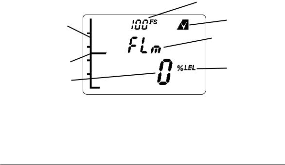
The Sensepoint XCD RFD display features an LCD with Numeric and bar-graph gas concentration data, alpha-numeric warning and status indication, a target for magnetic switch activation and the UP/DOWN/ESC/ENTER zones for remote configuration. The
LCD is also backlit with hi-intensity multi-colour LED indicator to show NORMAL, ALARM and FAULT status.
During normal operation the instrument display shows a steady GREEN backlight.
During Low and High Gas Alarm it displays a flashing RED backlight
During Fault condition the instrument display shows a flashing YELLOW backlight.
The screen is visible through the window of the transmitter’s cover. The display shows the gas concentration (both graphically and numerically), range, units, alarm/
fault status, etc.
Note: The detector display may become sluggish in sub-zero temperatures and possibly unclear at temperatures below -40 °C, but the detector continues its gas monitoring function. The display is not damaged and recovers when the temperature increases.
Full Scale
Bar Graph
(Proportional Test Pass Icon
to gas reading)
Gas Type
|
Peak Reading bar |
Measuring |
|
Gas Reading |
Unit |
Diagram 10: Example of a Flammable Transmitter Display screen – Normal Operation
24
 Loading…
Honeywell Sensepoint XCD: List of Available Documents
Note for Owners:
Guidesimo.com webproject is not a service center of Honeywell trademark and does not carries out works for diagnosis and repair of faulty Honeywell Sensepoint XCD equipment. For quality services, please contact an official service center of Honeywell company. On our website you can read and download documentation for your Honeywell Sensepoint XCD device for free and familiarize yourself with the technical specifications of device.
More Gas Detectors Devices:
-
EsiWelma Sensigas URD40SE
EsiWelma Srl URD40SE — EW0526D1_en.docx CO2 gas detectors – URD40SE 16/06/2017 Gas detection systems for industrial environments 1/4 Gas detectors Carbon dioxide (CO2) ATEX certified (II 2G Ex d IIC T6) URD40SE Sssssss 11…14Vdc power supply. Non Dispersive Infrared (NDIR) sensor designed for the detection of carbon dioxide (CO2). Up to three alarm thresholds plus sensing eleme …
Sensigas URD40SE Gas Detectors, 4
-
SAFETY SIREN Pro Series3
http://radongasdetectorreviews.com Page 1 Pro Series3 Radon Gas Detector HS71512 User Guide CONTENTS 1. Radon Gas – Facts and Concerns 2. Placement of the Detector 3. Installation of the Detector 4. Areas to be Avoided 5. Display Features 5.1 Short-Term Display 5.2 Long-Term Display 6. Initial Start-Up 7. Audible Alarm 8. Menu Button Operation 8.1 Long-Term / Short-Term 8.2 Test …
Pro Series3 Gas Detectors, 9
-
ion science GasCheck G 1
Register your instrument online to receive your extended Warranty. GasCheck G Instrument User Manual V2.4 Unrivalled Gas Detection. ionscience.com …
GasCheck G 1 Gas Detectors, 26
-
Bacharach HGM300
HGM300 / RDM800 Refrigerant Monitoring System Instruction 3015-4149 Installation & Operation Mini Manual Rev. 8 – April 2006 SECTION 1 (Page 2) Introduction, standard accessories and mounting specifications SECTION 2 (Page3) Suggested location of HGM300/RDM800 and pickup points SECTION 3 (Page 4) HGM300/RDM800 component locations SECTION 4 (Page6) Basic HGM300/RDM800 monitor syst …
HGM300 Measuring Instruments, 24
-
ION FALCO
Register your instrument online to receive your extended Warranty. FALCO and FALCOTAC Instrument User Manual V1.2R Unrivalled Gas Detection. ionscience.com 30 AÑOS AL SERVICIO DE LA INDUSTRIA …
FALCO Gas Detectors, 46