-
Contents
-
Table of Contents
-
Bookmarks
Related Manuals for Jeep 1996 Grand Cherokee
Summary of Contents for Jeep 1996 Grand Cherokee
-
Page 1
Welcome to the 1996 ZJ Jeep Grand Cherokee Electronic Service Manual and Supplement Click on logo to begin CLICK HERE FOR INSTRUCTIONS… -
Page 2
UNITED STATES The special service tools referred to herein are required for certain service operations. These special service tools or their equivalent, if not obtainable through a local source, are available through the following outlet. 28635 Mound Road, Warren, Michigan 48092, U.S.A. MILLER SPECIAL TOOLS OTC Division, SPX Corporation Telephone 1-800-801-5420… -
Page 3
SERVICE AND OWNER MANUALS Available for Chrysler, Plymouth, Dodge, Dodge Truck, and Jeep vehicles. Telephone orders may be placed at the number below. Credit cards are accepted (no CODs). Please have your l l l l l l l l l l l l order information available at time of call. -
Page 4
CHRYSLER CORPORATION SERVICE MANUAL and SUPPLEMENT 1996 JEEP GRAND CHEROKEE To order the special service tools used and illustrated, please refer to the instructions on inside back cover. NO PART OF THIS PUBLICATION MAY BE REPRODUCED, STORED IN A RETRIEVAL SYS-… -
Page 5
FOREWORD The information contained in this service manual has been prepared for the professional automotive tech- nician involved in daily repair operations. This manual does not cover theory of operation, which is addressed in service training material. Information describing the operation and use of standard and optional equipment is included in the Owner’s Manual provided with the vehicle. -
Page 6: Table Of Contents
GROUP TAB LOCATOR PAGE NOTE: Groups with the suffix “-S” are Supplements to Introduction the original service manual publication. Lubrication and Maintenance Lubrication and Maintenance Suspension Differential and Driveline Differential and Driveline Brakes Cooling System Battery Starting Systems Charging System Ignition System Instrument Panel Systems Audio Systems…
-
Page 8
VEHICLE IDENTIFICATION NUMBER DECODING CHART POSITION INTERPRETATION CODE = DESCRIPTION Country of Origin 1 = United States Make J = Jeep Vehicle Type 4 = MPV Gross Vehicle Weight Rating G = 5001-6000 lbs. Vehicle Line X = Grand Cherokee 4X2 (LHD) -
Page 9: Body Code Plate
INTRODUCTION GENERAL INFORMATION (Continued) VEHICLE SAFETY CERTIFICATION LABEL A vehicle safety certification label (Fig. 1) is attached to every Chrysler Corporation vehicle. The label certifies that the vehicle conforms to all appli- cable Federal Motor Vehicle Safety Standards. The label also lists: •…
-
Page 10: Fastener Identification
INTRODUCTION GENERAL INFORMATION (Continued) Vehicle Dimensions VEHICLE DIMENSIONS the head of the bolt. The higher the class number, the greater the bolt strength. Some metric nuts are The Vehicle Dimensions chart provides the dimen- imprinted with a single-digit strength class on the sions for each type of Grand Cherokee vehicle.
-
Page 11
INTRODUCTION GENERAL INFORMATION (Continued) INTERNATIONAL CONTROL AND DISPLAY SYMBOLS TORQUE REFERENCES Individual Torque Charts appear at the end of many Groups. Refer to the Standard Torque Specifi- cations Chart for torque references not listed in the individual torque charts. Fig. 3 Thread Notation—SAE and Metric use the chart to convert between millimeters (mm) and inches (in.) -
Page 12
INTRODUCTION GENERAL INFORMATION (Continued) FASTENER IDENTIFICATION… -
Page 13
INTRODUCTION GENERAL INFORMATION (Continued) FASTENER STRENGTH… -
Page 14
INTRODUCTION GENERAL INFORMATION (Continued) Fig. 4 Metric Prefixes CONVERSION FORMULAS AND EQUIVALENT VALUES… -
Page 15
INTRODUCTION GENERAL INFORMATION (Continued) METRIC CONVERSION… -
Page 16
INTRODUCTION GENERAL INFORMATION (Continued) TORQUE SPECIFICATIONS… -
Page 18: Lubrication And Maintenance
LUBRICATION AND MAINTENANCE 0 — 1 LUBRICATION AND MAINTENANCE CONTENTS page page GENERAL INFORMATION ….1 MAINTENANCE SCHEDULES ….3 JUMP STARTING, HOISTING AND TOWING .
-
Page 19
0 — 2 LUBRICATION AND MAINTENANCE GENERAL INFORMATION (Continued) Fig. 3 NLGI Symbol FLUID CAPACITIES Fig. 2 API Symbol ENGINE OIL FUEL TANK SAE GRADE RATING INDICATES ENGINE OIL VISCOSITY All……87.4 L (23 gal.) An SAE viscosity grade is used to specify the vis- ENGINE OIL W/FILTER CHANGE cosity of engine oil. -
Page 20: Maintenance Schedules
LUBRICATION AND MAINTENANCE 0 — 3 MAINTENANCE SCHEDULES INDEX page page GENERAL INFORMATION SCHEDULE—B ……5 INTRODUCTION .
-
Page 21
0 — 4 LUBRICATION AND MAINTENANCE GENERAL INFORMATION (Continued) • Drain and refill automatic transmission fluid. 82,500 Miles (132 000 km) or at 66 months • Drain and refill transfer case fluid. • Change engine oil. • Replace engine oil filter. 37,500 Miles (60 000 km) or at 30 months •… -
Page 22
LUBRICATION AND MAINTENANCE 0 — 5 GENERAL INFORMATION (Continued) **Recommended for proper vehicle performance for 27,000 Miles (43 000 km) • Change engine oil. vehicles built for sale in California. • Replace engine oil filter. IMPORTANT: Inspection and service should also •… -
Page 23
0 — 6 LUBRICATION AND MAINTENANCE GENERAL INFORMATION (Continued) • Inspect brake linings. 51,000 Miles (82 000 km) • Change engine oil. 75,000 Miles (120 000 km) • Replace engine oil filter. • Change engine oil. • Flush and replace engine coolant. •… -
Page 24
LUBRICATION AND MAINTENANCE 0 — 7 GENERAL INFORMATION (Continued) • Inspect brake linings. • Lubricate steering linkage (4×4 only). 99,000 Miles (158 000 km) 117,000 Miles (187 000 km) • Change engine oil. • Change engine oil. • Replace engine oil filter. •… -
Page 25
0 — 8 LUBRICATION AND MAINTENANCE JUMP STARTING, HOISTING AND TOWING INDEX page page SERVICE PROCEDURES JUMP STARTING PROCEDURE ….8 EMERGENCY TOW HOOKS ….10 TOWING RECOMMENDATIONS . -
Page 26
LUBRICATION AND MAINTENANCE 0 — 9 SERVICE PROCEDURES (Continued) • Do not tow a vehicle in a manner that could DISCONNECT CABLE CLAMPS AS FOLLOWS: • Disconnect BLACK cable clamp from engine jeopardize the safety of the operator, pedestrians or ground on disabled vehicle. -
Page 27
AND CAUSE SERIOUS INJURY. tow dollies under rear wheels. Some Jeep vehicles are equipped with front emer- FOUR-WHEEL-DRIVE VEHICLE TOWING gency tow hooks. The tow hooks should be used for EMERGENCY purposes only. -
Page 28
LUBRICATION AND MAINTENANCE 0 — 11 SERVICE PROCEDURES (Continued) NOTE: When a frame-contact type hoist is used, verify that the lifting pads are positioned properly (Fig. 3). WARNING: THE HOISTING AND JACK LIFTING POINTS PROVIDED ARE FOR A COMPLETE VEHI- CLE. -
Page 30
SUSPENSION 2 — 1 SUSPENSION CONTENTS page page ALIGNMENT ……1 REAR SUSPENSION ….. . 13 FRONT SUSPENSION . -
Page 31
2 — 2 SUSPENSION SERVICE PROCEDURES (Continued) Wheel Alignment Measurements (1) Tires with the same recommended air pressure, (4) Inspect ball studs, linkage pivot points and size, and tread wear. Refer to Group 22, Wheels and steering gear for looseness, roughness, binding or a Tires for diagnosis information. -
Page 32
SUSPENSION 2 — 3 SERVICE PROCEDURES (Continued) SUSPENSION AND STEERING SYSTEM DIAGNOSIS… -
Page 33
2 — 4 SUSPENSION 1996 Grand Cherokee SERVICE PROCEDURES (Continued) Publication No. 81-370-6147 TSB 26-04-96 April, 1996 Fig. 2 Drag Link and Tie Rod Clamp Fig. 1 Cam Adjuster TOE POSITION The toe position adjustment should be the last adjustment made. -
Page 34
SUSPENSION 2 — 5 1996 Grand Cherokee SERVICE PROCEDURES (Continued) Publication No. 81-370-6147 TSB 26-04-96 April, 1996 NOTE: Tighten the clamp bolt furthest from the REAR AXLE wheel first. Make sure the toe setting does not change during clamp tightening. -
Page 35: Front Suspension
2 — 6 SUSPENSION FRONT SUSPENSION INDEX page page DESCRIPTION AND OPERATION STABILIZER BAR ……9 FRONT SUSPENSION .
-
Page 36
SUSPENSION 2 — 7 DESCRIPTION AND OPERATION (Continued) replaceable ball studs attached to the axle tube usually be stopped by tightening the attaching nuts. yokes. If the noise persists, inspect for damaged and worn Shock Absorbers: The shock absorbers dampen bushings, and attaching components. -
Page 37
2 — 8 SUSPENSION REMOVAL AND INSTALLATION (Continued) INSTALLATION LOWER SUSPENSION ARM (1) Position the lower retainer and grommet on the upper stud. Insert the shock absorber through the REMOVAL shock tower hole. (1) Raise and support the vehicle. (2) Install the lower bolts and nuts. Tighten nuts (2) Paint or scribe alignment marks on the cam to 28 N·m (250 in. -
Page 38
SUSPENSION 2 — 9 REMOVAL AND INSTALLATION (Continued) (2) Install the rear bolts and finger tighten the new nuts. (3) Install a new cam bolt, cam and new nut in the axle. Re-align the reference marks. (4) Install the bolts and finger tighten the new nuts. -
Page 39
2 — 10 SUSPENSION REMOVAL AND INSTALLATION (Continued) Fig. 7 Stabilizer Bar (2) Install the links into the stabilizer bar and axle brackets. Tighten the nuts at the axle bracket finger tight. (3) Tighten the stabilizer bar to link nuts to 61 N·m (45 ft. -
Page 40
SUSPENSION 2 — 11 REMOVAL AND INSTALLATION (Continued) Fig. 9 Hub Bearing & Knuckle WHEEL MOUNTING STUDS (4) Remove lug nut and washers. (5) Install the brake rotor and caliper, refer to Group 5 Brakes for procedure. REMOVAL (1) Raise and support vehicle. (6) Install wheel and tire assembly, use new lug (2) Remove wheel and tire assembly. -
Page 41
2 — 12 SUSPENSION SPECIAL TOOLS FRONT SUSPENSION Remover/Installer Suspension Bushing 7932 Bolt, Special 7604 (J-21474–19) (J-35581) Nut, Long 7603 (J-21474–18) Remover C-4150A… -
Page 42: Rear Suspension
SUSPENSION 2 — 13 REAR SUSPENSION INDEX page page DESCRIPTION AND OPERATION SHOCK ABSORBER ….. . 14 REAR SUSPENSION ….. 13 STABILIZER BAR .
-
Page 43
2 — 14 SUSPENSION DIAGNOSIS AND TESTING INSTALLATION (1) Install the shock absorber on the upper frame SHOCK DIAGNOSIS rail stud. Install the shock absorber on the axle bracket. A noise from a shock absorber may be caused by (2) Install the retainer and nut on the stud. movement between mounting bushings and metal Tighten the upper nut to 70 N·m (52 ft. -
Page 44
SUSPENSION 2 — 15 REMOVAL AND INSTALLATION (Continued) (2) Disconnect the stabilizer bar links from the axle brackets (Fig. 4). (3) Lower the exhaust by disconnecting the muffler and tail pipe hangers. (4) Disconnect the stabilizer bar from the links. (5) Disconnect the stabilizer bar clamps from the frame rails. -
Page 45
2 — 16 SUSPENSION REMOVAL AND INSTALLATION (Continued) TRACK BAR INSTALLATION (1) Install the track bar to the axle bracket and install a new bolt. REMOVAL (1) Raise and support the vehicle. (2) It may be necessary to pry the axle assembly (2) Remove the bolt and nut from the frame rail over to install the track bar. -
Page 46: Propeller Shafts
DIFFERENTIAL AND DRIVELINE 3 — 1 DIFFERENTIAL AND DRIVELINE CONTENTS page page FRONT AXLE—TUBE AND MODEL 30 ..15 MODEL 44 AXLE ……75 MODEL 35 AXLE .
-
Page 47: General Information
3 — 2 DIFFERENTIAL AND DRIVELINE GENERAL INFORMATION (Continued) Fig. 1 Front & Rear Propeller Shafts—Typical 4WD which eliminates the need for a slip yoke. The CV joint has a splined shaft which allows the overall shaft length to be adjusted for optimum joint travel. This spline shaft is locked in place with a nut.
-
Page 48: Diagnosis And Testing
DIFFERENTIAL AND DRIVELINE 3 — 3 Fig. 4 Double Cardan U-Joint —Front Fig. 5 Constant Velocity Joint—Front Fig. 6 Reference Marks on Yokes DIAGNOSIS AND TESTING Driveline vibration can also result from loose or damaged engine mounts. Refer to Group 21, Trans- VIBRATION missions for additional information.
-
Page 49: Unbalance
3 — 4 DIFFERENTIAL AND DRIVELINE DIAGNOSIS AND TESTING (Continued) DRIVELINE VIBRATION UNBALANCE If propeller shaft unbalance is suspected, it can be verified with the following procedure: Removing and re–indexing the propeller shaft 180° may eliminate some vibrations. • Clean all the foreign material from the propeller shaft and the universal joints.
-
Page 50: Service Procedures
DIFFERENTIAL AND DRIVELINE 3 — 5 DIAGNOSIS AND TESTING (Continued) (9) If the clamps cause an additional unbalance, SERVICE PROCEDURES separate the clamps (1/4 inch above and below the mark). Repeat the vibration test (Fig. 9). UNIVERSAL JOINT ANGLE INFORMATION When two shafts come together at any common joint, the bend that is formed is called the operating angle.
-
Page 51: Propeller Shaft Angle Measurement
3 — 6 DIFFERENTIAL AND DRIVELINE SERVICE PROCEDURES (Continued) shaft angles will change according to the amount of load in the vehicle. Always check angles in loaded and unloaded conditions. • Check the condition of all suspension compo- nents and verify all fasteners are torqued to specifi- cations.
-
Page 52
DIFFERENTIAL AND DRIVELINE 3 — 7 SERVICE PROCEDURES (Continued) Fig. 14 Universal Joint Angle Example • At least 1/2 of one degree continuous operating (5) Remove bolts holding CV joint at front of shaft (propeller shaft) angle to front axle pinion yoke. (6) Remove bolts holding rear cardan-joint to the transfer case yoke. -
Page 53: Removal And Installation
3 — 8 DIFFERENTIAL AND DRIVELINE REMOVAL AND INSTALLATION (Continued) MEASUREMENT (2) Scribe alignment marks at the pinion shaft and This measurement is taken with the shaft installed at each end of the propeller shaft. These marks will and the vehicle at proper ride height. be used for installation reference.
-
Page 54
DIFFERENTIAL AND DRIVELINE 3 — 9 DISASSEMBLY AND ASSEMBLY (Continued) (3) Using a soft drift, tap the outside of the bear- (6) If the bearing assembly will not pull out by ing assembly to loosen snap ring. hand after pressing, tap the base of the lug near it to (4) Remove snap rings from both sides of yoke dislodge. -
Page 55: Double Cardan (Cv)
3 — 10 DIFFERENTIAL AND DRIVELINE DISASSEMBLY AND ASSEMBLY (Continued) ASSEMBLY (4) Press the bearing assembly into the cross hole (1) Apply extreme pressure (EP) N.L.G.I. Grade 1 enough to install a snap ring. Install a snap ring. or 2 grease to aid in installation. (5) Repeat steps 3 and 4 to install the opposite (2) Position the cross in the yoke with its lube fit- bearing assembly.
-
Page 56
DIFFERENTIAL AND DRIVELINE 3 — 11 DISASSEMBLY AND ASSEMBLY (Continued) (4) Press the bearing assembly partially from the (6) Flip assembly and repeat steps 4 and 5 for outboard side of the center yoke, enough to grasp by removing the opposite side bearing. This will then vise jaws (Fig. -
Page 57
3 — 12 DIFFERENTIAL AND DRIVELINE DISASSEMBLY AND ASSEMBLY (Continued) (2) Place a bearing assembly in a tube yoke hole (4) Flip the tube yoke and bearing assembly instal- and over a trunnion. Keep the needle bearings lation on the opposite trunnion. Install a snap ring upright in the bearing assembly (Fig. -
Page 58
DIFFERENTIAL AND DRIVELINE 3 — 13 DISASSEMBLY AND ASSEMBLY (Continued) (6) Install the centering kit assembly inside the (8) Press the remaining two bearing assemblies center yoke making sure the spring is in place (Fig. into place and install snap rings (Fig. 34). 32). -
Page 59: Cleaning And Inspection
3 — 14 DIFFERENTIAL AND DRIVELINE Adjust the pinion gear angle at the lower suspen- sion arms with shims (Fig. 38). Adding shims will decrease the pinion gear shaft angle but will increase the caster angle. The pinion gear shaft angle has pri- ority over the caster angle.
-
Page 60
DIFFERENTIAL AND DRIVELINE 3 — 15 FRONT AXLE—TUBE AND MODEL 30 INDEX page page GENERAL INFORMATION PINION SEAL REPLACEMENT ….22 INFORMATION ……15 STEERING KNUCKLE AND BALL STUDS . -
Page 61
3 — 16 DIFFERENTIAL AND DRIVELINE GENERAL INFORMATION (Continued) • The factory installed lubricant quantity for the non–disconnect type axle is 1.48 L (3.13 pts.). • The factory installed lubricant quantity for the vacuum–disconnect type axle is 1.65 L (3.76 pts.). Refer to Group 0, Lubrication and Maintenance for additional information regarding temperature range, viscosity and fluid level. -
Page 62
DIFFERENTIAL AND DRIVELINE 3 — 17 GENERAL INFORMATION (Continued) PINION GEAR DEPTH VARIANCE 2, intersecting figure is (–) 0.001 in. (0.025 mm). Sub- Using the wrong lubricant will cause overheating tract this amount from original shim. Refer to the and gear failure. Gear tooth cracking and bearing Pinion Gear Depth Variance Chart. -
Page 63
3 — 18 DIFFERENTIAL AND DRIVELINE DIAGNOSIS AND TESTING (Continued) driving condition. These conditions are acceleration, pinion gear shaft bore will also cause low speed deceleration, coast, or constant load. knock. When road testing, accelerate the vehicle to the VIBRATION speed range where the noise is the greatest. -
Page 64
DIFFERENTIAL AND DRIVELINE 3 — 19 DIAGNOSIS AND TESTING (Continued) FRONT DRIVE AXLE DIAGNOSIS… -
Page 65
3 — 20 DIFFERENTIAL AND DRIVELINE DIAGNOSIS AND TESTING (Continued) CONTINUED… -
Page 66
DIFFERENTIAL AND DRIVELINE 3 — 21 SERVICE PROCEDURES REMOVAL AND INSTALLATION LUBRICANT CHANGE DRIVE AXLE ASSEMBLY REPLACEMENT The gear lubricant will drain quicker if the vehicle REMOVAL has been recently driven. (1) Raise the vehicle and position support stands (1) Raise and support the vehicle. under the frame rails behind the lower suspension (2) Remove the lubricant fill hole plug from the arm frame brackets. -
Page 67
3 — 22 DIFFERENTIAL AND DRIVELINE REMOVAL AND INSTALLATION (Continued) (6) Install the shock absorber and tighten the bolt (7) Use Remover 7794A and slide hammer to to 23 N·m (17 ft. lbs.) torque. remove the pinion gear seal (Fig. 6). (7) Install the stabilizer bar link to the axle bracket. -
Page 68
DIFFERENTIAL AND DRIVELINE 3 — 23 REMOVAL AND INSTALLATION (Continued) (3) Remove the brake components from the axle, refer to Group 5, Brakes. (4) Remove the cotter pin, nut retainer and axle hub nut (Fig. 9). (5) Remove the hub to knuckle bolts (Fig. 9). Remove the hub from the steering knuckle and axle shaft. -
Page 69
3 — 24 DIFFERENTIAL AND DRIVELINE REMOVAL AND INSTALLATION (Continued) (8) Remove support and lower the vehicle. STEERING KNUCKLE AND BALL STUDS Ball Stud service procedures below require removal of the hub bearing and axle shaft. Removal and installation of upper and lower ball stud requires use of Tool Kit 6289 (J34503–A). -
Page 70
DIFFERENTIAL AND DRIVELINE 3 — 25 REMOVAL AND INSTALLATION (Continued) Fig. 12 Lower Ball Stud Remove/Install LOWER BALL STUD REPLACEMENT DIFFERENTIAL (1) Position tools as shown to remove and install ball stud (Fig. 12). Because there are two different REMOVAL designs for the lower ball studs try both installers for To service the differential the axle assembly and proper fit. -
Page 71
3 — 26 DIFFERENTIAL AND DRIVELINE REMOVAL AND INSTALLATION (Continued) (2) Remove the differential bearing caps. (3) Position Spreader W–129–B with the tool dowel pins seated in the locating holes (Fig. 14). Install the holddown clamps and tighten the tool turnbuckle fin- ger–tight. -
Page 72
DIFFERENTIAL AND DRIVELINE 3 — 27 REMOVAL AND INSTALLATION (Continued) (5) Install case in the housing. Tap the differential INNER AXLE SHAFT OIL SEAL REPLACEMENT case to ensure the bearings are fully seated (Fig. 17). Remove the spreader. SELECT–TRAC (1) Remove the inner axle shaft seals with a pry bay. -
Page 73
3 — 28 DIFFERENTIAL AND DRIVELINE REMOVAL AND INSTALLATION (Continued) (2) Remove the pinion gear seal with a slide ham- (6) Remove the rear bearing cup from housing mer or pry out with bar. (Fig. 23). Use Remover D– 149 and Handle C–4171. (3) Drive out pinion gear from housing with rawhide or plastic hammer (Fig. -
Page 74
DIFFERENTIAL AND DRIVELINE 3 — 29 REMOVAL AND INSTALLATION (Continued) PINION GEAR ASSEMBLY/INSTALLATION (1) Remove rear pinion bearing cup with Remover D–149 and Handle C– 4171. Place shims (and baffle if equipped) in the pinion gear rear bearing bore. Install the bearing cup with Installer D–146 and Driver Handle C–… -
Page 75
3 — 30 DIFFERENTIAL AND DRIVELINE REMOVAL AND INSTALLATION (Continued) • Original Bearings: 1 to 3 N·m (10 to 20 in. lbs.). (8) Install the yoke washer and old nut on the • New Bearings: 2 to 5 N·m (15 to 35 in. lbs.). pinion gear. -
Page 76
DIFFERENTIAL AND DRIVELINE 3 — 31 DISASSEMBLY AND ASSEMBLY (Continued) Fig. 31 Yoke Bearing Cap Removal (4) Release the vise jaws. Remove the sockets and bearing cap that was partially forced out of the yoke. (5) Repeat the above procedure for the remaining bearing cap. -
Page 77
3 — 32 DIFFERENTIAL AND DRIVELINE DISASSEMBLY AND ASSEMBLY (Continued) (4) Use a drift to remove the pinion gear mate shaft lock pin (Fig. 34). Fig. 36 Pinion Mate Gear Removal • Pinion gear mate shaft (align holes in shaft and Fig. -
Page 78
DIFFERENTIAL AND DRIVELINE 3 — 33 DISASSEMBLY AND ASSEMBLY (Continued) (3) Invert the differential case and start two ring gear bolts. This will provide case–to–ring gear bolt hole alignment. (4) Install new ring gear bolts and alternately tighten to 95–122 N·m (70–90 ft. lbs.) torque (Fig. 38). -
Page 79
3 — 34 DIFFERENTIAL AND DRIVELINE DISASSEMBLY AND ASSEMBLY (Continued) Fig. 43 Pinion Rear Bearing Cup Installation Fig. 41 Pinion Gear Depth Gauge Tools (1) Install the pinion front bearing cup with Installer D–144 and Handle C–4171 (Fig. 42). Fig. 44 Pinion Height Block Fig. -
Page 80
DIFFERENTIAL AND DRIVELINE 3 — 35 DISASSEMBLY AND ASSEMBLY (Continued) (5) Firmly place Scooter Block and Dial Indicator on pinion height block tool and zero the dial indicator pointer. (6) Slide the Scooter Block across the arbor while observing indicator (Fig. 46). Record the longest travel distance, whether inward (–) or outward (+), indicated by the pointer. -
Page 81
3 — 36 DIFFERENTIAL AND DRIVELINE DISASSEMBLY AND ASSEMBLY (Continued) ing on the hub with Bearing Installer C– 3716A and Driver Handle C–4171 (Fig. 49). Fig. 50 Ring Gear Backlash Measurement Fig. 49 Differential Bearing Installation (9) Position the remaining zero end–play shims on hub at opposite side of case. -
Page 82
DIFFERENTIAL AND DRIVELINE 3 — 37 DISASSEMBLY AND ASSEMBLY (Continued) Fig. 52 Gear Tooth Contact Patterns… -
Page 83
3 — 38 DIFFERENTIAL AND DRIVELINE DISASSEMBLY AND ASSEMBLY (Continued) • Wear or damage to pinion gear mate shaft, pin- FINAL ASSEMBLY ion gears, side gears and thrust washers. Replace as (1) Install the axle shafts. Refer to Axle Shaft a matched set only. -
Page 84
DIFFERENTIAL AND DRIVELINE 3 — 39 SPECIAL TOOLS FRONT AXLE—MODEL 30 Adapter—C-293-48 Puller—C-293-PA Puller—C-452 Extension—C293–3 Wrench—C-3281 Adapter—C-293-39 Dial Indicator—C-3339… -
Page 85
3 — 40 DIFFERENTIAL AND DRIVELINE SPECIAL TOOLS (Continued) Driver—C-3716-A Installer—D-146 Remover—D-147 Handle—C-4171 Remover—D-148 Installer—D-112 Remover—D-149 Installer—D-144… -
Page 86
DIFFERENTIAL AND DRIVELINE 3 — 41 SPECIAL TOOLS (Continued) Installer—D163 Remover/Installer—6289 Installer—W-162-D Tool Set, Pinion Depth—6774 Installer—6228 Installer—6764 Remover/Installer—6288 Puller—7794-A… -
Page 87
3 — 42 DIFFERENTIAL AND DRIVELINE SPECIAL TOOLS (Continued) Support—7919 Remover—7916 Installer—7917 Remover—7920 Screw, Forcing—7918… -
Page 88
DIFFERENTIAL AND DRIVELINE 3 — 43 MODEL 35 AXLE INDEX page page GENERAL INFORMATION DIFFERENTIAL ……54 GENERAL INFORMATION . -
Page 89
3 — 44 DIFFERENTIAL AND DRIVELINE GENERAL INFORMATION (Continued) CAUTION: If axle is submerged in water, lubricant must be replaced immediately to avoid possible premature axle failure. DESCRIPTION AND OPERATION AXLES The Model 35 axle is standard for XJ vehicles. The 8 1/4 axle is available in XJ vehicles without ABS brakes. -
Page 90
DIFFERENTIAL AND DRIVELINE 3 — 45 DESCRIPTION AND OPERATION (Continued) clutch packs contain multiple disc. The clutch will have radial grooves on the plates, and concentric grooves on the discs or bonded fiber material that is smooth appearance. In operation, the Trac-lok clutches are engaged by two concurrent forces. -
Page 91
3 — 46 DIFFERENTIAL AND DRIVELINE DIAGNOSIS AND TESTING driving condition. These conditions are acceleration, deceleration, coast, or constant load. GENERAL INFORMATION When road testing, accelerate the vehicle to the speed range where the noise is the greatest. Shift Axle bearing problem conditions are usually caused out–of–gear and coast through the peak–noise range. -
Page 92
DIFFERENTIAL AND DRIVELINE 3 — 47 DIAGNOSIS AND TESTING (Continued) • Damaged axle shaft bearings tance between the outside edges of the two pieces of • Loose pinion gear nut tape. Record this measurement as the rear of tire • Excessive pinion yoke run out (RTR) measurement. -
Page 93
3 — 48 DIFFERENTIAL AND DRIVELINE DIAGNOSIS AND TESTING (Continued) SERVICE DIAGNOSIS SERVICE DIAGNOSIS… -
Page 94
DIFFERENTIAL AND DRIVELINE 3 — 49 DIAGNOSIS AND TESTING (Continued) SERVICE DIAGNOSIS (CONT’D) -
Page 95
3 — 50 DIFFERENTIAL AND DRIVELINE DIAGNOSIS AND TESTING (Continued) TRAC-LOK NOISE DIAGNOSIS (6) If rotating torque is less than 22 N·m (30 ft. lbs.) or more than 271 N·m (200 ft. lbs.) on either If a noise occurs when turning corners, the most wheel the unit should be service. -
Page 96
DIFFERENTIAL AND DRIVELINE 3 — 51 SERVICE PROCEDURES (Continued) Trac–Lok Differentials; A container of Trac–Lok (5) Connect the brake hose at the axle junction block. lubricant (friction modifier) should be added after (6) Install the shock absorbers to the axle brackets repair service or a lubricant change. -
Page 97
3 — 52 DIFFERENTIAL AND DRIVELINE REMOVAL AND INSTALLATION (Continued) (9) Use Remover 7794A and slide hammer to CAUTION: Exercise care during the bearing preload remove the pinion gear seal (Fig. 9). torque adjustment. Do not over–tighten, or loosen and then re–tighten the nut. Do not exceed the bearing preload torque. -
Page 98
DIFFERENTIAL AND DRIVELINE 3 — 53 REMOVAL AND INSTALLATION (Continued) AXLE SHAFT (9) Inspect axle shaft seal for leakage or damage. (10) Inspect the roller bearing contact surface on the axle shaft for signs of brinelling, galling and pit- REMOVAL (1) Raise and support the vehicle. -
Page 99
3 — 54 DIFFERENTIAL AND DRIVELINE REMOVAL AND INSTALLATION (Continued) Fig. 16 Bearing Cap Identification Fig. 14 Axle Shaft Bearing Removal Tool Fig. 17 Spread Differential Housing (4) Install a pilot stud at the left side of the differ- ential housing. Attach Dial Indicator to housing pilot Fig. -
Page 100
DIFFERENTIAL AND DRIVELINE 3 — 55 REMOVAL AND INSTALLATION (Continued) Fig. 18 Differential Removal Fig. 19 Differential Installation DIFFERENTIAL INSTALLATION (1) Position Spreader W–129–B with the tool dowel pins seated in the locating holes (Fig. 17). Install the hold down clamps and tighten the tool turnbuckle finger–tight. -
Page 101
3 — 56 DIFFERENTIAL AND DRIVELINE REMOVAL AND INSTALLATION (Continued) Fig. 23 Ring Gear Removal RING GEAR INSTALLATION CAUTION: Do not reuse the bolts that held the ring gear to the differential case. The bolts can fracture causing extensive damage. Fig. -
Page 102
DIFFERENTIAL AND DRIVELINE 3 — 57 REMOVAL AND INSTALLATION (Continued) PINION GEAR (4) Remove the pinion gear seal with a slide ham- mer or pry out with bar. (5) Remove oil slinger, front bearing. REMOVAL (1) Remove differential assembly from axle hous- (6) Remove the front pinion bearing cup and seal ing. -
Page 103
3 — 58 DIFFERENTIAL AND DRIVELINE REMOVAL AND INSTALLATION (Continued) (8) Remove the collapsible preload spacer (Fig. 29). PINION GEAR INSTALLATION (1) Install the pinion rear bearing cup with Installer C—4308 and Driver Handle C–4171 (Fig. 31). Ensure cup is correctly seated. Fig. -
Page 104
DIFFERENTIAL AND DRIVELINE 3 — 59 REMOVAL AND INSTALLATION (Continued) (3) Install pinion front bearing, oil slinger. Apply a light coating of gear lubricant on the lip of pinion seal. Install seal with Installer D–163 and Handle C–4171 (Fig. 33). Fig. -
Page 105
3 — 60 DIFFERENTIAL AND DRIVELINE REMOVAL AND INSTALLATION (Continued) Fig. 36 Pinion Yoke Installation—Typical Fig. 38 Check Pinion Gear Rotation Torque Fig. 37 Tightening Pinion Nut • Original Bearings — 1 to 3 N·m (10 to 20 in. lbs.). •… -
Page 106
DIFFERENTIAL AND DRIVELINE 3 — 61 DISASSEMBLY AND ASSEMBLY (3) Remove the differential side gears and thrust washers. STANDARD DIFFERENTIAL DIFFERENTIAL ASSEMBLE (1) Differential side gears and thrust washers DISASSEMBLE (2) Pinion gears and thrust washers (1) Remove pinion gear mate shaft. (3) Pinion gear mate shaft (align holes in shaft (2) Rotate the differential side gears and remove and case) -
Page 107
3 — 62 DIFFERENTIAL AND DRIVELINE DISASSEMBLY AND ASSEMBLY (Continued) Fig. 44 Mate Shaft Lock Screw Fig. 42 Differential Case Holding Tool Fig. 45 Mate Shaft Removal Fig. 43 Ring Gear Removal (4) Remove the pinion gear mate shaft lock screw (Fig. -
Page 108
DIFFERENTIAL AND DRIVELINE 3 — 63 DISASSEMBLY AND ASSEMBLY (Continued) (7) Assemble Threaded Adapter 6960–1 into top side gear. Thread forcing Screw 6960–4 into adapter until it becomes centered in adapter plate. (8) Position a small screw driver in slot of Threaded Adapter 6960–1 (Fig. -
Page 109
3 — 64 DIFFERENTIAL AND DRIVELINE DISASSEMBLY AND ASSEMBLY (Continued) remain in position and are seated in the case pockets. Fig. 53 Clutch Discs & Lower Side Gear Installation (5) Install lubricated Step Plate 6960–3 on first clutch pack (Fig. 54). Fig. -
Page 110
DIFFERENTIAL AND DRIVELINE 3 — 65 DISASSEMBLY AND ASSEMBLY (Continued) (10) Rotate case with Turning Bar 6960–2 until (2) Inspect clutch pack plates for wear, scoring or mate shaft holes in pinion gears align with holes in damage. Replace both clutch packs if any one compo- case. -
Page 111
3 — 66 DIFFERENTIAL AND DRIVELINE ADJUSTMENTS (Continued) Fig. 57 Shim Locations Fig. 56 Pinion Gear Head Or if the old pinion is (–) 3 and the new pinion is (–) Compensation pinion depth variance 2, intersecting figure is (–) 0.001 in. (0.025 mm). Sub- achieved with select shims. -
Page 112
DIFFERENTIAL AND DRIVELINE 3 — 67 ADJUSTMENTS (Continued) Fig. 60 Gauge Tools In Housing—Typical travel distance, whether inward (–) or outward (+), indicated by the pointer. Fig. 58 Pinion Gear Depth Gauge Tools—Typical (1) Assemble Pinion Gauge Set, Pinion Block and pinion bearings. -
Page 113
3 — 68 DIFFERENTIAL AND DRIVELINE ADJUSTMENTS (Continued) (1) Install dummy side bearings 6927 on differen- tial. (2) Install the differential case in the axle housing. (3) Install the outboard shim/spacer (selected thickness) on each side between bearing cup and housing (Fig. -
Page 114
DIFFERENTIAL AND DRIVELINE 3 — 69 ADJUSTMENTS (Continued) If backlash must be adjusted, spacers are available in various thicknesses. Adjust the backlash accord- ingly (Fig. 65). Do not increase the total shim pack thickness, excessive bearing preload and damage will occur. Fig. -
Page 115
3 — 70 DIFFERENTIAL AND DRIVELINE Fig. 66 Gear Tooth Contact Patterns… -
Page 116
DIFFERENTIAL AND DRIVELINE 3 — 71 SPECIFICATIONS MODEL 35 AXLE Axle Type….Semi–Floating Hypoid Lubricant ..SAE Thermally Stable 80W–90 Lubricant Trailer Tow . -
Page 117
3 — 72 DIFFERENTIAL AND DRIVELINE SPECIAL TOOLS (Continued) Dial Indicator—C-3339 Arbor, Pinion—W-115-3 Installer—D-130 Driver—C-3716-A Installer—D-146 Handle—C-4171 Remover—D-147 Trac-lok Tool—C-4487… -
Page 118
DIFFERENTIAL AND DRIVELINE 3 — 73 SPECIAL TOOLS (Continued) Remover—D-148 Installer—6436 Installer—D163 Installer—6437 Plug—SP-3289 Disc, Axle Arbor—6732 Installer—W-162-D Gauge Block—6735… -
Page 119
3 — 74 DIFFERENTIAL AND DRIVELINE SPECIAL TOOLS (Continued) Tool Set, Pinion Depth—6774 Holder—6965 Trac-lok Tool Set—6960 Puller—7794-A… -
Page 120
DIFFERENTIAL AND DRIVELINE 3 — 75 MODEL 44 AXLE INDEX page page GENERAL INFORMATION DIFFERENTIAL ……85 GENERAL INFORMATION . -
Page 121
3 — 76 DIFFERENTIAL AND DRIVELINE DESCRIPTION AND OPERATION (Continued) It is not necessary to remove the axle from the When turning corners, the outside wheel must travel vehicle for service. A removable differential cover is a greater distance than the inside wheel in order to provided for routine vehicle service. -
Page 122
DIFFERENTIAL AND DRIVELINE 3 — 77 DESCRIPTION AND OPERATION (Continued) threaded pin. Differential bearing preload and ring gear backlash is adjusted by the use of spacer shims positioned between the side bearing race and the housing. Pinion bearing preload is set and main- tained by the use of a collapsible spacer. -
Page 123
3 — 78 DIFFERENTIAL AND DRIVELINE DIAGNOSIS AND TESTING (Continued) LOW SPEED KNOCK (2) Attach a one–inch long piece of masking tape at the center of each tire tread for use as reference Low speed knock is generally caused by a worn marks. -
Page 124
DIFFERENTIAL AND DRIVELINE 3 — 79 DIAGNOSIS AND TESTING (Continued) SERVICE DIAGNOSIS SERVICE DIAGNOSIS… -
Page 125
3 — 80 DIFFERENTIAL AND DRIVELINE DIAGNOSIS AND TESTING (Continued) SERVICE DIAGNOSIS (CONT’D) -
Page 126
DIFFERENTIAL AND DRIVELINE 3 — 81 DIAGNOSIS AND TESTING (Continued) TRAC-LOK NOISE DIAGNOSIS If a noise occurs when turning corners, the most probable cause is incorrect or contaminated lubri- cant. Before removing the Trac-lok unit for repair, drain, flush and refill the axle with the specified lubricant. -
Page 127
3 — 82 DIFFERENTIAL AND DRIVELINE SERVICE PROCEDURES (Continued) CAUTION: Overfilling the differential can result in (6) Install brake components refer to Group 5 lubricant foaming and overheating. Brakes. (7) Install axle vent hose Trac–Lok Differentials; A container of Trac–Lok (8) Align propeller shaft and pinion yoke reference lubricant (friction modifier) should be added after marks. -
Page 128
DIFFERENTIAL AND DRIVELINE 3 — 83 REMOVAL AND INSTALLATION (Continued) (9) Use Remover 7794A and slide hammer to preload torque. The collapsible preload spacer on the remove the pinion gear seal (Fig. 7). shaft will have to be replaced. The bearing preload torque will be re–adjusted afterward. -
Page 129
3 — 84 DIFFERENTIAL AND DRIVELINE REMOVAL AND INSTALLATION (Continued) (7) Continue tightening the shaft nut in small increments until the correct bearing rotation preload torque is attained. (8) Align the installation reference marks and attach the drive shaft to the yoke. (9) Add API grade GL 5 hypoid gear lubricant to the differential housing, if necessary. -
Page 130
DIFFERENTIAL AND DRIVELINE 3 — 85 REMOVAL AND INSTALLATION (Continued) (1) Note the installation reference letters stamped on the bearing caps and housing machined sealing surface (Fig. 15). Fig. 15 Bearing Cap Identification (2) Remove the differential bearing caps. (3) Position Spreader W–129–B with the tool dowel Fig. -
Page 131
3 — 86 DIFFERENTIAL AND DRIVELINE REMOVAL AND INSTALLATION (Continued) (5) Separate the housing enough to remove the (6) Install case in the housing. Tap the differential case from the housing. Measure the distance with the case to ensure the bearings are fully seated (Fig. 18). dial indicator (Fig. -
Page 132
DIFFERENTIAL AND DRIVELINE 3 — 87 REMOVAL AND INSTALLATION (Continued) DIFFERENTIAL SIDE BEARINGS REMOVAL (1) Remove Differential case from axle housing. (2) Remove the bearings from the differential case with Press 938, and Adapter 1130 (Fig. 20). Fig. 21 Install Differential Side Bearings Fig. -
Page 133
3 — 88 DIFFERENTIAL AND DRIVELINE REMOVAL AND INSTALLATION (Continued) (3) Remove the pinion gear from housing (Fig. 25). Catch the pinion with your hand to prevent it from falling and being damaged. Fig. 23 Ring Gear Bolt Installation PINION GEAR REMOVAL Fig. -
Page 134
DIFFERENTIAL AND DRIVELINE 3 — 89 REMOVAL AND INSTALLATION (Continued) (7) Remove the rear bearing cup from housing (Fig. 27). Use Remover C-4307 and Handle C–4171. Fig. 29 Inner Bearing Removal Fig. 27 Rear Bearing Cup Removal PINION GEAR INSTALLATION (1) Install the pinion rear bearing cup with (8) Remove the collapsible preload spacer (Fig. -
Page 135
3 — 90 DIFFERENTIAL AND DRIVELINE REMOVAL AND INSTALLATION (Continued) (2) Install the pinion front bearing cup with (4) Place the proper thickness depth shim on the Installer D–129 and Handle C–4171 (Fig. 31). pinion gear and install the rear bearing. (5) Install the rear bearing (and slinger if used) on the pinion gear with Installer 6448 (Fig. -
Page 136
DIFFERENTIAL AND DRIVELINE 3 — 91 REMOVAL AND INSTALLATION (Continued) • New Bearings — 2 to 5 N·m (15 to 35 in. lbs.). (7) Install yoke with Installer W–162D Wrench 6719 (Fig. 35). Fig. 35 Pinion Yoke Installation—Typical (8) Install the yoke washer and a new nut on the pinion gear. -
Page 137
3 — 92 DIFFERENTIAL AND DRIVELINE REMOVAL AND INSTALLATION (Continued) Install the housing cover within 5 minutes after applying the sealant. (3) Install the cover on the differential with the attaching bolts. Install the identification tag. Tighten the cover bolts to 41 N·m (30 ft. lbs.) torque. CAUTION: Overfilling the differential can result in lubricant foaming and overheating. -
Page 138
DIFFERENTIAL AND DRIVELINE 3 — 93 DISASSEMBLY AND ASSEMBLY (Continued) DISASSEMBLY (4) Remove the pinion gear mate shaft lock screw Service to the Trac–Lok differential requires the (Fig. 43). use of Tool Set C–4487 (J–23781). Refer to Model 44 Axle section in this Group for Differential Removal and Installation. -
Page 139
3 — 94 DIFFERENTIAL AND DRIVELINE DISASSEMBLY AND ASSEMBLY (Continued) (6) Install and lubricate Step Plate C–4487–1 (Fig. (9) Tighten forcing screw tool 122 N·m (90 ft. lbs.) 45). (maximum) to compress Belleville springs in clutch packs (Fig. 47). Fig. 47 Tighten Belleville Spring Compressor Tool (10) Using a 0.020 in. -
Page 140
DIFFERENTIAL AND DRIVELINE 3 — 95 DISASSEMBLY AND ASSEMBLY (Continued) (11) Loosen the forcing screw tool until the clutch ASSEMBLY pack tension is relieved and the pinion gears can be The clutch discs are replaceable as complete sets slightly rattled between the case and side gears. only. -
Page 141
3 — 96 DIFFERENTIAL AND DRIVELINE DISASSEMBLY AND ASSEMBLY (Continued) (5) Install lubricated Step Plate C–4487–1 on first CLEANING AND INSPECTION clutch pack (Fig. 53). AXLE COMPONENTS Wash differential components with cleaning solvent and dry with compressed air. Do not steam clean the differential components. -
Page 142
DIFFERENTIAL AND DRIVELINE 3 — 97 ADJUSTMENTS PINION GEAR DEPTH GENERAL INFORMATION Ring and pinion gears are supplied as matched sets only. The identifying numbers for the ring and pinion gear are etched into the face of each gear (Fig. 54). -
Page 143
3 — 98 DIFFERENTIAL AND DRIVELINE ADJUSTMENTS (Continued) PINION GEAR DEPTH VARIANCE Fig. 58 Pinion Height Block—Typical (4) Slide the Scooter Block across the arbor while observing indicator (Fig. 60). Record the longest travel distance, whether inward (–) or outward (+), indicated by the pointer. -
Page 144
DIFFERENTIAL AND DRIVELINE 3 — 99 ADJUSTMENTS (Continued) Fig. 59 Gauge Tools In Housing—Typical Fig. 61 Differential Bearing Shim Installation Fig. 60 Pinion Gear Depth Measurement—Typical DIFFERENTIAL BEARING PRELOAD AND GEAR LASH DIFFERENTIAL SHIM PACK MEASUREMENT NOTE: It is recommended whenever bearings are removed that they be replaced. -
Page 145
3 — 100 DIFFERENTIAL AND DRIVELINE ADJUSTMENTS (Continued) The differential bearings must be preloaded to compensate for heat and load during opera- tion. (9) Add an additional 0.004–in. (0.1 mm) to each outboard shim/spacer for bearing preload. (10) Remove differential from axle housing. (11) Remove dummy bearings. -
Page 146
DIFFERENTIAL AND DRIVELINE 3 — 101 SPECIFICATIONS (Continued) Fig. 65 Gear Tooth Contact Patterns… -
Page 147
3 — 102 DIFFERENTIAL AND DRIVELINE SPECIFICATIONS (Continued) TORQUE DESCRIPTION TORQUE Bolts, Diff. Cover … . .41 N·m (30 ft. lbs.) Bolts, Diff. Bearing Cap ..85 N·m (63 ft. lbs.) Bolts, Ring Gear . -
Page 148
DIFFERENTIAL AND DRIVELINE 3 — 103 SPECIAL TOOLS (Continued) Installer—D-163 Splitter—1130 Installer—D-129 Remover—6310 Remover—D-103 Installer—6436 Installer—W-162–D Installer—6437… -
Page 149
3 — 104 DIFFERENTIAL AND DRIVELINE SPECIAL TOOLS (Continued) Installer—6448 Adapter Set—6956 Holder—6963 Holder—6719 Adapter—6790 Remover—7794-A Pinion Depth Set—6955… -
Page 150
BRAKES 5 — 1 BRAKES CONTENTS page page ANTILOCK BRAKES ….. . 34 BASE BRAKE SYSTEM ….. 1 BASE BRAKE SYSTEM INDEX page… -
Page 151: General Information
5 — 2 BRAKES GENERAL INFORMATION CAUTION: Use Mopar brake fluid, or an equivalent quality fluid meeting SAE/DOT standards J1703 and BRAKE SYSTEM DOT 3. Brake fluid must be clean and free of con- taminants. Use fresh fluid from sealed containers All vehicles are equipped with power assist four- only to ensure proper antilock component opera- wheel disc brakes.
-
Page 152: Combination Valve
BRAKES 5 — 3 DESCRIPTION AND OPERATION (Continued) Power assist is generated by utilizing the pressure MASTER CYLINDER differential between normal atmospheric pressure The master cylinder has a removable nylon reser- and a vacuum. The vacuum needed for booster oper- voir (Fig.
-
Page 153: Front Disc Brakes
5 — 4 BRAKES DESCRIPTION AND OPERATION (Continued) Fig. 2 Master Cylinder pressure in the separate front/rear brake hydraulic circuits. A decrease or loss of fluid pressure in either hydraulic circuit will cause the switch valve to shut- tle to the low pressure side. Movement of the valve pushes the switch plunger upward.
-
Page 154
BRAKES 5 — 5 DESCRIPTION AND OPERATION (Continued) PARKING BRAKES The parking brakes are operated by a cable and hand lever system. Three cables are used, consisting of one front cable and two rear cables. All three cables are interconnected at the cable tensioner and equalizer mechanism. -
Page 155
5 — 6 BRAKES DIAGNOSIS AND TESTING (Continued) of vehicle and listen for noise that might be caused SPONGY PEDAL by loose, worn or damaged suspension or steering A spongy pedal is most often caused by air in the components. system. -
Page 156
BRAKES 5 — 7 DIAGNOSIS AND TESTING (Continued) If brake drag occurs at all wheels, the problem dirt contaminated, cleaning and/or replacement will may be related to a blocked master cylinder return be necessary. port, or faulty power booster (binds-does not release). BRAKE SQUEAK/SQUEAL BRAKE FADE Brake squeak or squeal may be due to linings that… -
Page 157: Red Brake Warning Lamp
5 — 8 BRAKES DIAGNOSIS AND TESTING (Continued) STOP LAMP SWITCH the front or rear wheel brake hydraulic circuit. It will also illuminate at startup as part of a bulb check. Stop lamp switch operation can be tested with an If the light comes on, first verify that the parking ohmmeter.
-
Page 158: Combination Valve
BRAKES 5 — 9 DIAGNOSIS AND TESTING (Continued) Pressure Differential Switch (1) Have helper sit in drivers seat to apply brake pedal and observe red brake warning light. (2) Raise vehicle on hoist. (3) Connect bleed hose to a rear wheel cylinder and immerse hose end in container partially filled with brake fluid.
-
Page 159: Parking Brake
5 — 10 BRAKES DIAGNOSIS AND TESTING (Continued) Fig. 12 Thickness Specification On Rear Rotor Measure rotor thickness at four to six points Fig. 10 Measuring Rotor Thickness Variation around the rotor face. Position the micrometer approximately 3/4 inch from the rotor outer circum- ference for each measurement (Fig.
-
Page 160: Service Procedures
BRAKES 5 — 11 DIAGNOSIS AND TESTING (Continued) If the red lamp comes on while the vehicle is in The steel brake lines should be inspected periodi- motion and brake pedal height decreases, a fault has cally for evidence of corrosion, twists, kinks, leaks, or occurred in the front or rear brake hydraulic system.
-
Page 161
5 — 12 BRAKES SERVICE PROCEDURES (Continued) MANUAL BLEEDING (1) Remove reservoir filler caps and fill reservoir with Mopar, or equivalent quality DOT 3 brake fluid. (2) If calipers, or wheel cylinders were overhauled, open all caliper and wheel cylinder bleed screws. Then close each bleed screw as fluid starts to drip from it. -
Page 162
BRAKES 5 — 13 SERVICE PROCEDURES (Continued) CAUTION: Do not machine the rotor if it will cause line. Special bending tools are needed to avoid kink- the rotor to fall below minimum allowable thick- ing or twisting metal brake line. In addition, special flaring tools are needed to provide the inverted-type, ness. -
Page 163: Removal And Installation
5 — 14 BRAKES REMOVAL AND INSTALLATION (5) Remove nut securing pedal shaft in support bracket. STOP LAMP SWITCH (6) Slide pedal shaft outward for clearance and remove brake pedal. REMOVAL (7) Remove pedal bushings if they are to be (1) Remove steering column cover and lower trim replaced.
-
Page 164
BRAKES 5 — 15 REMOVAL AND INSTALLATION (Continued) (2) Disconnect brakelines that connect combination (6) Bleed brakes. valve to HCU. MASTER CYLINDER (3) Disconnect wire from combination valve switch terminal. Be careful when separating wire connector REMOVAL as lock tabs are easily damaged if not fully disen- (1) Remove brakelines from master cylinder. -
Page 165: Disc Brake Caliper
5 — 16 BRAKES REMOVAL AND INSTALLATION (Continued) (6) (b) Install booster attaching nuts on studs. Tighten attaching nuts to 41 N·m (30 ft. lbs.). (7) (c) Slide booster push rod on pedal pin. Then secure rod to pin with retainer clip. (8) (5) In engine compartment, attach vacuum hose to booster check valve.
-
Page 166
BRAKES 5 — 17 REMOVAL AND INSTALLATION (Continued) Then rotate caliper over rotor and seat notches at (4) Remove caliper mounting bolts (Fig. 27). upper end of shoes on mounting ledge. (4) Coat caliper mounting bolts with GE 661 or Dow 111 silicone grease. -
Page 167
5 — 18 BRAKES REMOVAL AND INSTALLATION (Continued) Fig. 29 Outboard Brakeshoe Removal Fig. 31 Caliper Lubrication Points Fig. 30 Inboard Brakeshoe Removal unseat dust boot and force dirt into piston bore. INSTALLATION (1) Clean brakeshoe mounting ledge slide surfaces of steering knuckle with wire brush. -
Page 168: Disc Brake Rotor
BRAKES 5 — 19 REMOVAL AND INSTALLATION (Continued) REAR DISC BRAKE CALIPER REMOVAL (1) Raise vehicle and remove tire and wheel assemblies. (2) Press caliper piston into caliper bore with C-clamp (Fig. 35). (3) Remove caliper mounting bolts (Fig. 36). (4) Rotate caliper rearward by hand or with pry tool.
-
Page 169
5 — 20 BRAKES REMOVAL AND INSTALLATION (Continued) (3) Connect rear brake hose to caliper. Use new washers on hose fitting and tighten hose fitting bolt to 24-38 N·m (216-336 in. lbs.). (4) Check brake hose position before proceeding. Verify that hose is not twisted, kinked, or touching any suspension components. -
Page 170
BRAKES 5 — 21 REMOVAL AND INSTALLATION (Continued) Fig. 40 Correct Brakeshoe Position Fig. 41 Backing Off Parking Brake Shoes REAR DISC BRAKE ROTOR (7) Pump brake pedal to seat caliper piston and brakeshoes. Do not move vehicle until firm brake REMOVAL pedal is obtained. -
Page 171: Front Parking Brake Cable
5 — 22 BRAKES REMOVAL AND INSTALLATION (Continued) (12) Connect battery negative cable. FRONT PARKING BRAKE CABLE REMOVAL (1) Release parking brakes. (2) Disconnect battery negative cable and raise vehicle on hoist. (3) Remove front cable adjusting nut and disen- gage cable tensioner from equalizer.
-
Page 172: Parking Brakeshoes
BRAKES 5 — 23 REMOVAL AND INSTALLATION (Continued) (2) Disengage cable at equalizer. Then disengage cable from body and chassis clips and retainers. (3) Slide cable eyelet off actuating lever (Fig. 45). (4) Compress retainer securing cable in bracket attached to caliper bracket. Then remove cable from bracket.
-
Page 173
5 — 24 BRAKES REMOVAL AND INSTALLATION (Continued) PARKING BRAKE CAM AND LEVER NOTE: The cams are reversible and can be used on either wheel. The levers are NOT reversible. They are marked R and L and the lever notch (for the cable eyelet), must faces rearward on both sides. -
Page 174: Boot
BRAKES 5 — 25 REMOVAL AND INSTALLATION (Continued) (10) Note position of cam and lever for installation reference. Then remove cam and lever from splash shield and bracket. (11) Separate splash shield and caliper bracket. Then remove lever boot from bracket (Fig. 53). Fig.
-
Page 175
5 — 26 BRAKES REMOVAL AND INSTALLATION (Continued) (Fig. 55). Rubber part of boot extends through rear (7) Install parking brakeshoes on splash shield. opening in bracket. Allow adhesive on boot and bracket Verify positioning of cam and lever, shoes, springs to set up for a minute or two before proceeding. -
Page 176: Disassembly And Assembly
BRAKES 5 — 27 DISASSEMBLY AND ASSEMBLY (5) Remove reservoir by rocking it to one side and pulling free of grommets (Fig. 61). MASTER CYLINDER RESERVOIR REMOVAL (1) Remove reservoir cap and empty fluid into drain container. (2) Remove pins that retain reservoir to master cylinder.
-
Page 177: Disc Brake Caliper
5 — 28 BRAKES DISASSEMBLY AND ASSEMBLY (Continued) (2) Start reservoir in grommets. Then rock reser- voir back and forth while pressing downward to seat it in grommets. (3) Install pins that retain reservoir to cylinder body. (4) Fill and bleed master cylinder on bench before installation in vehicle.
-
Page 178
BRAKES 5 — 29 DISASSEMBLY AND ASSEMBLY (Continued) Fig. 68 Mounting Bolt Bushing And Boot Fig. 71 Dust Boot On Piston (3) Install bushing boots in caliper, then insert bushing into boot and push bushing into place (Fig. 69). Fig. 72 Caliper Piston Installation (7) Press caliper piston to bottom of bore. -
Page 179: Rear Disc Brake Caliper
5 — 30 BRAKES DISASSEMBLY AND ASSEMBLY (Continued) (9) Replace caliper bleed screw if removed. REAR DISC BRAKE CALIPER DISASSEMBLY (1) Remove caliper and brakeshoes. (2) Remove mounting bolt boots and bushings from caliper (Fig. 74). Fig. 76 Caliper Piston Removal Fig.
-
Page 180: Cleaning And Inspection
BRAKES 5 — 31 DISASSEMBLY AND ASSEMBLY (Continued) (3) Lubricate caliper piston with clean brake fluid (9) Install bushing and boot assemblies in caliper. and start piston into bore and seal by hand. Use a Be sure boots are centered in caliper as shown. twisting, rocking motion to start piston into seal.
-
Page 181: Parking Brake Cable Tensioner
5 — 32 BRAKES CLEANING AND INSPECTION (Continued) corroded, rusted, scored, or if polishing would (7) Lower vehicle enough for access to parking increase bore diameter more than 0.025 mm (0.001 brake lever. Then fully apply parking brakes. Leave inch). brakes applied until adjustment is complete.
-
Page 182: Brake Components
BRAKES 5 — 33 SPECIFICATIONS (Continued) TORQUE CHART DESCRIPTION TORQUE Brake Pedal Support Bolt ..23-34 N·m (17-25 ft. lbs.) Pivot Bolt/Nut ..27-35 N·m (20-26 ft. lbs.) Brake Booster Mounting Nuts .
-
Page 183: Antilock Brakes
• Hydraulic Control Unit (HCU) • Wheel Speed Sensors (WSS) • Acceleration Switch • Main Relay And Pump Motor Relay Fig. 1 Jeep ABS System • ABS Warning Light static and dynamic self check of system electrical • Pump Motor Sensor components.
-
Page 184
BRAKES 5 — 35 DESCRIPTION AND OPERATION (Continued) light and registers a fault code in the microprocessor els, it at the right side of the steering column. In memory. right hand drive models, it is near the cowl panel The CAB contains dual microprocessors. A logic NORMAL BRAKING block in each microprocessor receives identical sensor The CAB monitors wheel speed sensor inputs con-… -
Page 185
5 — 36 BRAKES DESCRIPTION AND OPERATION (Continued) The HCU provides three channel pressure control to the front and rear brakes. One channel controls the rear wheel brakes in tandem. The two remaining channels control the front wheel brakes individually. During antilock braking, the solenoid valves are opened and closed as needed. -
Page 186
BRAKES 5 — 37 DESCRIPTION AND OPERATION (Continued) Fig. 7 Wheel Speed Sensors sensors have an air gap spacer attached to the sensor pickup face. The spacer establishes correct air gap when pressed against the tone ring during installa- tion. As the tone ring rotates, it peels the spacer off the sensor to create the required air gap. -
Page 187
5 — 38 BRAKES DESCRIPTION AND OPERATION (Continued) The switch (Fig. 8), provides an additional vehicle An ABS circuit fault is indicated when the amber deceleration reference during 4-wheel drive opera- lamp remains on after startup, or illuminates at any tion. -
Page 188
BRAKES 5 — 39 REMOVAL AND INSTALLATION (Continued) (2) Remove mounting nut and remove controller (Fig. 9). Fig. 10 HCU Solenoid Harness Connector Fig. 9 Controller Antilock Brakes INSTALLATION (1) Install controller on mounting stud. (2) Install mounting nut and tighten to 6 N·m (55 in. -
Page 189
5 — 40 BRAKES REMOVAL AND INSTALLATION (Continued) Fig. 15 HCU Bracket Bolts Fig. 13 HCU Brakeline Connections Fig. 16 HCU Bracket Isolators And Sleeves (2) Position stud plate on underside of panel and secure it with new retaining nuts (Fig. 17). Fig. -
Page 190
BRAKES 5 — 41 REMOVAL AND INSTALLATION (Continued) (3) Install HCU bracket on mounting studs and tighten bracket mounting nuts to 10-13 N·m (92-112 in. lbs.). (4) Start brakeline fittings into ports at rear of HCU. Start fittings by hand to avoid cross threading. -
Page 191
5 — 42 BRAKES REMOVAL AND INSTALLATION (Continued) REAR WHEEL SPEED SENSOR spacer from sensor pickup face. Set air gap to 0.92- 1.45 mm (0.036-0.057 in.) with feeler gauge (Fig. 23). Tighten sensor bolt to 14 N·m (11 ft. lbs.). REMOVAL (1) Raise and fold rear seat forward. -
Page 192
BRAKES 5 — 43 REMOVAL AND INSTALLATION (Continued) Fig. 25 Acceleration Sensor Mounting (3) Tilt rear seat assembly forward for access to SPECIFICATIONS sensor. (4) Disconnect sensor harness (Fig. 25). TORQUE CHART (5) Remove screws attaching sensor to bracket. (6) Remove sensor. DESCRIPTION TORQUE Acceleration Sensor… -
Page 194
COOLING SYSTEM 7 — 1 COOLING SYSTEM CONTENTS page page GENERAL INFORMATION VISCOUS FAN DRIVE ….22 COOLANT ……2 WATER PUMP TESTS . -
Page 195: General Information
7 — 2 COOLING SYSTEM GENERAL INFORMATION (Continued) COOLING SYSTEM The cooling system regulates engine operating tem- perature. It allows the engine to reach normal oper- ating temperature as quickly as possible. It also maintains normal operating temperature and pre- vents overheating.
-
Page 196
COOLING SYSTEM 7 — 3 DESCRIPTION AND OPERATION (Continued) Fig. 2 Engine Cooling System—5.2L Engine—Typical • Some reserve coolant to the radiator to cover minor leaks and evaporation or boiling losses. As the engine cools, a vacuum is formed in the cooling system of both the radiator and engine. -
Page 197
7 — 4 COOLING SYSTEM DESCRIPTION AND OPERATION (Continued) Fig. 5 Block Heater—4.0L 6-Cyl. Engine Fig. 4 Coolant Reserve/Overflow Tank—Typical dle of the section of belt being tested (between two pulleys) to check tension. Do not allow the gauge (or gauge adapter) to contact anything but the belt. -
Page 198: Coolant Selection-Additives
COOLING SYSTEM 7 — 5 DESCRIPTION AND OPERATION (Continued) lems. These are: longer engine warmup time, unreli- ene-glycol. The freeze point of 50/50 propylene-glycol able warmup performance, increased exhaust and water is -32 deg. C (-26 deg. F). 5 deg. C higher emissions and crankcase condensation.
-
Page 199
7 — 6 COOLING SYSTEM DESCRIPTION AND OPERATION (Continued) spring-loaded pressure relief valve. This valve opens cated by the antifreeze in the coolant mixture. No when system pressure reaches the release range of additional lubrication is necessary. 97-to-124 kPa (14-to-18 psi). CAUTION: All 4.0L 6-cylinder engines are equipped with a reverse (counterclockwise) rotating water pump and thermal viscous fan drive assembly. -
Page 200: Viscous Fan Drive
COOLING SYSTEM 7 — 7 DESCRIPTION AND OPERATION (Continued) Fig. 9 Coolant Return Tube—5.2L V-8 Engine Fig. 11 Clamp Number/Letter Location Inspect the hoses at regular intervals. Replace WARNING: CONSTANT TENSION HOSE CLAMPS hoses that are cracked, feel brittle when squeezed, or ARE USED ON MOST COOLING SYSTEM HOSES.
-
Page 201: Diagnosis And Testing
7 — 8 COOLING SYSTEM DESCRIPTION AND OPERATION (Continued) of the radiator discharge air. It engages the viscous CAUTION: If the viscous fan drive is replaced fan drive for higher fan speed if the air temperature because of mechanical damage, the cooling fan from the radiator rises above a certain point.
-
Page 202: Drb Scan Tool
COOLING SYSTEM 7 — 9 DIAGNOSIS AND TESTING (Continued) Fig. 14 Check Engine Lamp Location Certain criteria must be met for a DTC to be entered into PCM memory. The criteria may be a specific range of engine rpm, engine temperature Fig.
-
Page 203: On-Board Diagnostics (Obd)
7 — 10 COOLING SYSTEM DIAGNOSIS AND TESTING (Continued) ler is loose and can be held with the rod while the THERMOSTAT fan blades are turning, the pump is defective. Do not use excessive force when rotating pump shaft. If the ON-BOARD DIAGNOSTICS impeller turns, the pump is OK.
-
Page 204
COOLING SYSTEM 7 — 11 DIAGNOSIS AND TESTING (Continued) SERPENTINE ACCESSORY DRIVE BELT DIAGNOSIS—4.0L 6-CYLINDER ENGINE… -
Page 205
7 — 12 COOLING SYSTEM DIAGNOSIS AND TESTING (Continued) -
Page 206
COOLING SYSTEM 7 — 13 DIAGNOSIS AND TESTING (Continued) SERPENTINE ACCESSORY DRIVE BELT DIAGNOSIS—5.2L 8-CYLINDER ENGINE… -
Page 207: Preliminary Checks
7 — 14 COOLING SYSTEM DIAGNOSIS AND TESTING (Continued) PRELIMINARY CHECKS (4) RECENT SERVICE OR ACCIDENT REPAIR: Determine if any recent service has been per- formed on vehicle that may effect cooling system. ENGINE COOLING SYSTEM OVERHEATING Establish what driving conditions caused the com- This may be: •…
-
Page 208
COOLING SYSTEM 7 — 15 DIAGNOSIS AND TESTING (Continued) COOLING SYSTEM… -
Page 209
7 — 16 COOLING SYSTEM DIAGNOSIS AND TESTING (Continued) -
Page 210
COOLING SYSTEM 7 — 17 DIAGNOSIS AND TESTING (Continued) -
Page 211
7 — 18 COOLING SYSTEM DIAGNOSIS AND TESTING (Continued) -
Page 212
COOLING SYSTEM 7 — 19 DIAGNOSIS AND TESTING (Continued) -
Page 213
7 — 20 COOLING SYSTEM DIAGNOSIS AND TESTING (Continued) -
Page 214: Radiator Coolant Flow Check
ULTRAVIOLET LIGHT METHOD Inspect the cams on the outside part of the filler All Jeep models have a leak detection additive neck. If the cams are bent, seating of pressure cap added to the cooling system before they leave the fac- valve and tester seal will be affected.
-
Page 215: Viscous Fan Drive
7 — 22 COOLING SYSTEM DIAGNOSIS AND TESTING (Continued) leakage. If no leaks are visible, inspect for internal Drain sufficient coolant to allow for thermostat leakage. Large radiator leak holes should be repaired removal. Refer to Thermostat Replacement. Discon- by a reputable radiator repair shop. nect the water pump drive belt.
-
Page 216
COOLING SYSTEM 7 — 23 DIAGNOSIS AND TESTING (Continued) WARNING: USE EXTREME CAUTION WHEN THE HOSE TO DETERMINE WHEN PRESSURE HAS ENGINE IS OPERATING. DO NOT STAND IN A BEEN RELEASED. WHEN COOLANT AND STEAM DIRECT LINE WITH THE FAN. DO NOT PUT YOUR STOP BEING PUSHED INTO TANK AND SYSTEM HANDS NEAR THE PULLEYS, BELTS OR FAN. -
Page 217: Service Procedures
7 — 24 COOLING SYSTEM DIAGNOSIS AND TESTING (Continued) LOW COOLANT LEVEL-AERATION from radiator drain cock. Do this while observing coolant reserve/overflow system tank. The coolant If the coolant level in radiator drops below top of level in reserve/overflow tank should drop slightly. If radiator core tubes, air will enter cooling system.
-
Page 218
COOLING SYSTEM 7 — 25 SERVICE PROCEDURES (Continued) (2) Fill system using a 50/50 mixture of ethylene- glycol anifreeze and low mineral conent water. Fill radiator to top and install radiator cap. Add suffi- cient coolant to the reserve/overflow tank to raise level to FULL mark. -
Page 219: Removal And Installation
7 — 26 COOLING SYSTEM SERVICE PROCEDURES (Continued) cooling tube passages. For more information, refer to operating instructions supplied with flushing equip- ment. Have radiator cleaned more extensively by a radiator repair shop. REVERSE FLUSHING ENGINE Drain the cooling system. Remove the thermostat housing and thermostat.
-
Page 220
COOLING SYSTEM 7 — 27 REMOVAL AND INSTALLATION (Continued) (2) Install lower hose and hose clamp to cooler. Hose clamp screws must be facing towards rear of vehicle. Tighten clamp to 2 N·m (18 in. lbs.) torque. (3) Install upper hose and hose clamp at cooler. Hose clamp screws must be facing towards rear of vehicle. -
Page 221
7 — 28 COOLING SYSTEM REMOVAL AND INSTALLATION (Continued) Fig. 29 Hose Clamp Tool—Typical CAUTION: A number or letter is stamped into the tongue of constant tension clamps (Fig. 30). If replacement is necessary, use only an original equipment clamp with matching number or letter. Fig. -
Page 222
COOLING SYSTEM 7 — 29 REMOVAL AND INSTALLATION (Continued) (13) If pump is to be replaced, the heater hose fit- ting must be removed. Note position of fitting before removal. INSTALLATION (1) If pump is being replaced, install the heater hose fitting to the pump. -
Page 223
7 — 30 COOLING SYSTEM REMOVAL AND INSTALLATION (Continued) any of these conditions are found. Also check condi- ALWAYS WEAR SAFETY GLASSES WHEN SERVIC- tion of the thermal viscous fan drive. Refer to Viscous ING CONSTANT TENSION CLAMPS. Fan Drive in this group. The water pump can be removed without discharg- CAUTION: A number or letter is stamped into the ing the air conditioning system (if equipped). -
Page 224
COOLING SYSTEM 7 — 31 REMOVAL AND INSTALLATION (Continued) Fig. 36 Water Pump Bolts—5.2L Engine—Typical (15) Loosen clamp at water pump end of bypass hose (Fig. 32). Slip bypass hose from water pump while removing pump from vehicle. Discard old gas- ket. -
Page 225: Radiator
7 — 32 COOLING SYSTEM REMOVAL AND INSTALLATION (Continued) CAUTION: When installing the serpentine acces- Do not waste reusable coolant. If the solution is sory drive belt, belt must be routed correctly. If not, clean, drain the coolant into a clean container for reuse.
-
Page 226: Thermostat 5.2L Engine
COOLING SYSTEM 7 — 33 REMOVAL AND INSTALLATION (Continued) INSTALLATION THERMOSTAT 5.2L ENGINE (1) Install the replacement thermostat so that the pellet, which is encircled by a coil spring, faces the REMOVAL engine. All thermostats are marked on the outer WARNING: DO NOT LOOSEN RADIATOR DRAIN- flange to indicate the proper installed position.
-
Page 227
7 — 34 COOLING SYSTEM REMOVAL AND INSTALLATION (Continued) (d) Remove belt from vehicle. (e) Remove two generator mounting bolts. Do not remove any wiring at generator. If equipped with 4WD, unplug 4WD indicator lamp wiring har- ness (located near rear of generator). (f) Remove generator. -
Page 228
COOLING SYSTEM 7 — 35 REMOVAL AND INSTALLATION (Continued) CAUTION: When installing the serpentine acces- DRAINCOCK WITH THE SYSTEM HOT AND UNDER sory drive belt, belt must be routed correctly. If not, PRESSURE. SERIOUS BURNS FROM COOLANT engine may overheat due to water pump rotating in CAN OCCUR. -
Page 229
7 — 36 COOLING SYSTEM REMOVAL AND INSTALLATION (Continued) (4) 4.0L Engine: Remove the four fan hub-to-wa- ter pump pulley mounting nuts (Fig. 48). Carefully remove the fan assembly from the water pump pulley and position to center of fan shroud. Fan belt removal is not necessary as the water pump studs will hold the pump pulley in position. -
Page 230
COOLING SYSTEM 7 — 37 REMOVAL AND INSTALLATION (Continued) Fig. 48 Fan Mounting Nuts—4.0L 6-Cyl. Engine Fig. 50 Radiator and A/C Condenser Mounting holes. Before removal, mark the original position of the crossmember. Fig. 49 Fan Blade and Viscous Fan Drive—5.2L V-8 Engine Fig. -
Page 231
7 — 38 COOLING SYSTEM REMOVAL AND INSTALLATION (Continued) (14) Remove the upper brace bolt from each of the two radiator braces (Fig. 50). (15) Remove crossmember-to-radiator mounting nuts (Fig. 51). (16) Working through grill opening, remove the lower bracket bolt securing lower part of hood latch support bracket to lower frame crossmember (Fig. -
Page 232
COOLING SYSTEM 7 — 39 REMOVAL AND INSTALLATION (Continued) (2) Not equipped with air conditioning: Gently (20) 4.0L Engine: Install the four nuts securing lower the radiator into the vehicle. Guide the two the fan assembly to the water pump (Fig. 48). radiator alignment dowels through the holes in the Tighten nuts to 27 N·m (20 ft. -
Page 233
7 — 40 COOLING SYSTEM REMOVAL AND INSTALLATION (Continued) Fig. 54 Clamp Number/Letter Location Fig. 55 Generator and A/C Compressor Mounting (3) Loosen both bypass hose clamps (Fig. 53) and Bracket—5.2L Engine position to center of hose. Remove hose from vehicle. (3) Remove upper radiator hose clamp (Fig. -
Page 234
COOLING SYSTEM 7 — 41 REMOVAL AND INSTALLATION (Continued) (8) Remove accessory drive belt as follows: The 55) to 54 N·m (40 ft. lbs.) torque. Tighten bolts (num- drive belt is equipped with a spring loaded automatic ber 3) (Fig. 55) to 40 N·m (30 ft. lbs.) torque. belt tensioner (Fig. -
Page 235
7 — 42 COOLING SYSTEM REMOVAL AND INSTALLATION (Continued) ENGINE BLOCK HEATER REMOVAL (1) Disconnect negative battery cable from battery. (2) Drain coolant from radiator. Refer to Draining Cooling System in this group. (3) Raise vehicle. (4) Remove engine cylinder block drain plug(s) located on the sides of cylinder block above the oil pan rail (Fig. -
Page 236
COOLING SYSTEM 7 — 43 REMOVAL AND INSTALLATION (Continued) BELT REPLACEMENT/ADJUSTMENT NOTE: The belt routing schematics are published from the latest information available at the time of publication. If anything differs between these sche- matics and the Belt Routing Label, use the sche- matics on Belt Routing Label. -
Page 237
7 — 44 COOLING SYSTEM REMOVAL AND INSTALLATION (Continued) Fig. 66 Belt Routing—5.2L Engine Fig. 65 Belt Tensioner—5.2L Engine (2) Rotate tensioner assembly clockwise (as viewed has been used 15 minutes or less. If this specifica- from front) until tension has been relieved from belt. tion cannot be met, check for: The wrong belt being installed (incorrect length/ (3) Remove belt from idler pulley first. -
Page 238
COOLING SYSTEM 7 — 45 REMOVAL AND INSTALLATION (Continued) center of fan shroud. Fan belt removal is not neces- sary as the water pump studs will hold the pump pulley in position. Do not remove fan assembly from vehicle at this time. Fig. -
Page 239: Viscous Fan Drive
7 — 46 COOLING SYSTEM REMOVAL AND INSTALLATION (Continued) (4) Remove the four fan blade-to-viscous fan drive mounting bolts. Remove viscous fan drive from fan blades. (5) After removing fan blade/fan drive assembly do not place the thermal viscous fan drive in the hori- zontal position.
-
Page 240: Cleaning And Inspection
COOLING SYSTEM 7 — 47 REMOVAL AND INSTALLATION (Continued) • Impeller rubs either the pump body or timing for approximately two minutes. This will ensure proper fluid distribution within the drive. chain case/cover CLEANING AND INSPECTION SPECIFICATIONS RADIATOR CAP INFORMATION The following specifications are published from the INSPECTION latest information available at the time of publica-…
-
Page 241: Drive Belt Tension
7 — 48 COOLING SYSTEM SPECIFICATIONS (Continued) DRIVE BELT TENSION SPECIAL TOOLS COOLING Pliers 6094 TORQUE Pressure Tester 7700–A…
-
Page 242
BATTERY 8A — 1 BATTERY CONTENTS page page GENERAL INFORMATION HYDROMETER TEST ….. 6 INTRODUCTION ……1 IGNITION-OFF DRAW TEST . -
Page 243: General Information
8A — 2 BATTERY GENERAL INFORMATION (Continued) condition. See Built-In Test Indicator in this group most abnormal or transient voltages caused by the for more information. switching of any of the vehicle’s electrical compo- It is important that the battery, starting, and nents.
-
Page 244: Diagnosis And Testing
BATTERY 8A — 3 DESCRIPTION AND OPERATION (Continued) BATTERY MOUNTING THE BATTERY IS RETURNED TO SERVICE. PER- SONAL INJURY AND/OR VEHICLE DAMAGE MAY The battery is mounted to a molded plastic tray RESULT FROM LOOSE OR MISSING CELL CAPS. located in the right front corner of the engine com- partment.
-
Page 245
8A — 4 BATTERY DIAGNOSIS AND TESTING (Continued) Battery Diagnosis… -
Page 246
BATTERY 8A — 5 DIAGNOSIS AND TESTING (Continued) 2. A loose or worn generator drive belt. IF THE BATTERY IS EQUIPPED WITH REMOV- 3. Electrical loads that exceed the output of the ABLE CELL CAPS, BE CERTAIN THAT EACH OF charging system. -
Page 247: Hydrometer Test
8A — 6 BATTERY DIAGNOSIS AND TESTING (Continued) HYDROMETER TEST CAUTION: Exercise care when inserting the tip of the hydrometer into a cell to avoid damaging the The hydrometer test reveals the battery state-of- plate separators. Damaged plate separators can charge by measuring the specific gravity of the elec- cause early battery failure.
-
Page 248: Load Test
BATTERY 8A — 7 DIAGNOSIS AND TESTING (Continued) is not available; or, for maintenance-free batteries See the Open-Circuit Voltage chart. This voltage with non-removable cell caps. reading will indicate the battery state-of-charge, but will not reveal its cranking capacity. If a battery has WARNING: an open-circuit voltage reading of 12.4 volts or IF THE BATTERY SHOWS SIGNS OF FREEZING,…
-
Page 249
8A — 8 BATTERY DIAGNOSIS AND TESTING (Continued) (2) Connect a suitable volt-ammeter-load tester (Fig. 5) to the battery posts (Fig. 6). Refer to the operating instructions provided with the tester being used. Check the open-circuit voltage (no load) of the battery. -
Page 250: Service Procedures
BATTERY 8A — 9 DIAGNOSIS AND TESTING (Continued) IGNITION-OFF DRAW TEST nuity between the battery negative terminal post and cable clamp is lost during any part of the IOD test, Ignition-Off Draw (IOD) refers to power being the electronic timer function will be activated and all drained from the battery with the ignition switch in tests must be repeated.
-
Page 251
8A — 10 BATTERY SERVICE PROCEDURES (Continued) WARNING: test, return the battery to use. If the battery will not IF THE BATTERY SHOWS SIGNS OF FREEZING, endure a load test, it is faulty and must be replaced. Clean and inspect the battery holddowns, tray, ter- LEAKING, LOOSE POSTS, OR LOW ELECTROLYTE LEVEL, TEST,… -
Page 252: Removal And Installation
BATTERY 8A — 11 SERVICE PROCEDURES (Continued) may be good and the charging should be completed in REMOVAL AND INSTALLATION the normal manner. BATTERY Charge Rate (1) Turn the ignition switch to the Off position. Make sure all electrical accessories are off. Voltage Hours (2) Loosen the cable terminal clamps and discon-…
-
Page 253
8A — 12 BATTERY REMOVAL AND INSTALLATION (Continued) WARNING: WEAR A SUITABLE PAIR OF RUBBER GLOVES (NOT THE HOUSEHOLD TYPE) WHEN REMOVING BATTERY HAND. SAFETY GLASSES SHOULD ALSO BE WORN. IF THE BAT- TERY IS CRACKED OR LEAKING, THE ELECTRO- LYTE CAN BURN THE SKIN AND EYES. -
Page 254
BATTERY 8A — 13 REMOVAL AND INSTALLATION (Continued) cleaner, and a sodium bicarbonate (baking soda) and warm water cleaning solution (Fig. 15). Fig. 16 Battery Cables (14) Install and tighten the battery positive cable terminal clamp. Then install and tighten the nega- tive cable terminal clamp. -
Page 256: Starting Systems
STARTING SYSTEMS 8B — 1 STARTING SYSTEMS CONTENTS page page GENERAL INFORMATION CONTROL CIRCUIT TESTS ….5 INTRODUCTION ……1 FEED CIRCUIT TESTS .
-
Page 257
8B — 2 STARTING SYSTEMS DESCRIPTION AND OPERATION (Continued) • The starter motor must not be clamped in a The energized solenoid pull-in coil pulls in the sole- noid plunger. The solenoid plunger pulls the shift lever vise by the starter field frame. Doing so may dam- in the starter. -
Page 258
STARTING SYSTEMS 8B — 3 DIAGNOSIS AND TESTING (Continued) • Park/Neutral Position Switch — Visually inspect • Starter — Visually inspect the starter for indica- the park/neutral position switch for indications of phys- tions of physical damage and loose or corroded wiring ical damage and loose or corroded wiring connections. -
Page 259
8B — 4 STARTING SYSTEMS DIAGNOSIS AND TESTING (Continued) COLD CRANKING TEST When performing these tests, it is important to remember that the voltage drop is giving an indica- For circuit descriptions and diagrams, refer to tion of the resistance between the two points at 8W-21 — Starting System in Group 8W — Wiring Dia- which the voltmeter probes are attached. -
Page 260
STARTING SYSTEMS 8B — 5 DIAGNOSIS AND TESTING (Continued) is detected, correct the poor contact between the cable clamp and the terminal post. Fig. 5 Test Ground Circuit Resistance — Typical (5) Connect the positive lead of the voltmeter to the starter housing. -
Page 261
8B — 6 STARTING SYSTEMS DIAGNOSIS AND TESTING (Continued) SOLENOID TEST and 30. If OK, see the Relay Circuit Test in this Remove the starter as described in this group. group. If not OK, replace the faulty relay. Then proceed as follows: (1) Disconnect the wire from the solenoid field coil terminal. -
Page 262
STARTING SYSTEMS 8B — 7 DIAGNOSIS AND TESTING (Continued) PARK/NEUTRAL POSITION SWITCH TEST (1) Place the transmission gear selector lever in the Park position. (2) Disconnect and isolate the battery negative cable. (3) Raise and support the vehicle. (4) Disconnect the park/neutral position switch harness connector. -
Page 263
8B — 8 STARTING SYSTEMS REMOVAL AND INSTALLATION (Continued) (3) Disconnect the battery cable and solenoid feed wire from the starter solenoid (Fig. 9). (4) Remove the lower starter mounting bolt and exhaust brace (Fig. 11). Fig. 12 Power Distribution Center (8) Test the relay operation. -
Page 264
CHARGING SYSTEM 8C — 1 CHARGING SYSTEM CONTENTS page page GENERAL INFORMATION CHARGING SYSTEM ….. . 2 OVERVIEW ……1 CURRENT OUTPUT TEST . -
Page 265: Description And Operation
8C — 2 CHARGING SYSTEM DESCRIPTION AND OPERATION (Continued) electronic memory for any failure it detects. See On- Board Diagnostic System Test in this group for more information. GENERATOR The generator is belt-driven by the engine using a serpentine type drive belt. It is serviced only as a complete assembly.
-
Page 266: Charging System Resistance Tests
CHARGING SYSTEM 8C — 3 DIAGNOSIS AND TESTING (Continued) receptacles. They should be properly installed and PREPARATION tight. Repair or replace as required. (1) Before starting test, make sure battery is in (3) Inspect the electrolyte level in the battery. good condition and is fully-charged.
-
Page 267
8C — 4 CHARGING SYSTEM DIAGNOSIS AND TESTING (Continued) Charging System Test… -
Page 268: Current Output Test
CHARGING SYSTEM 8C — 5 DIAGNOSIS AND TESTING (Continued) CURRENT OUTPUT TEST TEST 1 (1) Perform the previous test Preparation. The current output test will determine if the (2) Fully engage the parking brake. charging system can deliver its minimum test cur- (3) Start engine.
-
Page 269: On-Board Diagnostic System Test
8C — 6 CHARGING SYSTEM DIAGNOSIS AND TESTING (Continued) (5) Adjust carbon pile rheostat (load) and engine ON-BOARD DIAGNOSTIC SYSTEM TEST speed in slow increments until a speed of 1250 rpm, and a voltmeter reading of 15 volts is obtained. GENERAL INFORMATION Immediately record ammeter reading.
-
Page 270: Removal And Installation
CHARGING SYSTEM 8C — 7 DIAGNOSIS AND TESTING (Continued) Fig. 3 Generator Diagnostic Trouble Code ERASING DIAGNOSTIC TROUBLE CODES The DRB Scan Tool must be used to erase a DTC. REMOVAL AND INSTALLATION GENERATOR WARNING: DISCONNECT NEGATIVE CABLE FROM BATTERY BEFORE REMOVING BATTERY OUTPUT WIRE FROM GENERATOR.
-
Page 271: Specifications Generator Ratings
8C — 8 CHARGING SYSTEM REMOVAL AND INSTALLATION (Continued) Fig. 6 Battery Temperature Sensor Location (2) Disconnect the sensor pigtail harness from the engine wire harness. (3) Pry the sensor straight up from the battery tray mounting hole. Fig. 5 Remove/Install Generator Connectors— INSTALLATION Typical (1) Feed the pigtail harness through the hole in…
-
Page 272: Ignition System
IGNITION SYSTEM 8D — 1 IGNITION SYSTEM CONTENTS page page GENERAL INFORMATION MAP SENSOR ……8 INTRODUCTION .
-
Page 273: General Information
8D — 2 IGNITION SYSTEM GENERAL INFORMATION INTRODUCTION This group describes the ignition systems for both 5.2L V–8 and 4.0L 6–cylinder engines. On Board Diagnostics is described in Group 25, Emission Control Systems. Group 0, Lubrication and Maintenance, contains general maintenance information (in time or mileage intervals) for ignition related items.
-
Page 274: Automatic Shutdown (Asd) Relay
IGNITION SYSTEM 8D — 3 DESCRIPTION AND OPERATION (Continued) Do not attempt to modify the distributor hous- CRANKSHAFT POSITION SENSOR—5.2L V-8 ing to get distributor rotation. Distributor posi- ENGINE tion will have no effect on ignition timing. The Engine speed and crankshaft position are provided position of the distributor will determine fuel through the crankshaft position sensor.
-
Page 275
8D — 4 IGNITION SYSTEM DESCRIPTION AND OPERATION (Continued) Fig. 5 Sensor Operation—4.0L 6-Cyl. Engine Fig. 4 Crankshaft Position Sensor Location—4.0L 6-Cyl. Engine injection and spark events. It is also used to synchro- nize the fuel injectors with their respective cylinders. other inputs, to determine injector sequence and igni- When the leading edge of the pulse ring (shutter) tion timing. -
Page 276: Engine
IGNITION SYSTEM 8D — 5 DESCRIPTION AND OPERATION (Continued) IGNITION SWITCH AND KEY LOCK CYLINDER The ignition switch is located on the steering col- umn. The Key-In-Switch is located in the ignition switch module. For diagnosis of the Key-In-Switch, refer to Group, 8U. A column shift interlock device is used to lock the transmission shifter in the Park position when the key is in the Off position.
-
Page 277
8D — 6 IGNITION SYSTEM DIAGNOSIS AND TESTING (Continued) voltmeter to a good ground. Determine that sufficient battery voltage (12.4 volts) is present for the starting and ignition systems. (4) Determine that sufficient battery voltage (12.4 volts) is present for the starting and ignition systems. (5) Crank the engine for 5 seconds while monitor- ing the voltage at the coil positive terminal: •… -
Page 278: Distributor
IGNITION SYSTEM 8D — 7 DIAGNOSIS AND TESTING (Continued) (6) Remove test lead from the coil positive termi- nal. Connect an 18 gauge jumper wire between the battery positive terminal and the coil positive termi- nal. (7) Make the special jumper shown in (Fig. 10). Using the jumper, momentarily ground the ignition coil driver circuit at the PCM connector (cavity A-7).
-
Page 279: Crankshaft Position Sensor-5.2L Engines
8D — 8 IGNITION SYSTEM DIAGNOSIS AND TESTING (Continued) IGNITION TIMING (1) Near the rear of the intake manifold, discon- nect sensor pigtail harness connector from main wir- ing harness. NOTE: Base (initial) ignition timing is NOT adjust- able on any 4.0L/5.2L engine. Do not attempt to (2) Place an ohmmeter across terminals B and C adjust ignition timing by rotating the distributor.
-
Page 280: Spark Plug Cables
IGNITION SYSTEM 8D — 9 DIAGNOSIS AND TESTING (Continued) (5) 4.0L Engine: Remove distributor cap from dis- tributor (two screws). Rotate (crank) the engine until the distributor rotor is pointed to approximately the 11 o’clock position. The movable pulse ring should now be within the sensor pickup.
-
Page 281: Spark Plug Conditions
8D — 10 IGNITION SYSTEM DIAGNOSIS AND TESTING (Continued) insulators should be in good condition and should fit the other end of the test probe along the entire tightly on the coil, distributor and spark plugs. Spark length of all spark plug cables. If cables are cracked plug cables with insulators that are cracked or torn or punctured, there will be a noticeable spark jump must be replaced.
-
Page 282
IGNITION SYSTEM 8D — 11 DIAGNOSIS AND TESTING (Continued) Fig. 19 Normal Operation and Cold (Carbon) Fouling Some fuel refiners in several areas of the United States have introduced a manganese additive (MMT) for unleaded fuel. During combustion, fuel with MMT causes the entire tip of the spark plug to be coated with a rust colored deposit. -
Page 283
8D — 12 IGNITION SYSTEM DIAGNOSIS AND TESTING (Continued) SCAVENGER DEPOSITS dissolves first and the ground electrode dissolves some- Fuel scavenger deposits may be either white or yellow what latter (Fig. 24). Insulators appear relatively (Fig. 22). They may appear to be harmful, but this is a deposit free. -
Page 284: Removal And Installation
IGNITION SYSTEM 8D — 13 REMOVAL AND INSTALLATION SPARK PLUG CABLES CAUTION: When disconnecting a high voltage cable from a spark plug or from the distributor cap, twist the rubber boot slightly (1/2 turn) to break it loose (Fig. 26). Grasp the boot (not the cable) and pull it off with a steady, even force.
-
Page 285
8D — 14 IGNITION SYSTEM REMOVAL AND INSTALLATION (Continued) (2) Prior to removing the spark plug, spray com- PLUG INSTALLATION pressed air around the spark plug hole and the area Special care should be taken when installing spark around the spark plug. This will help prevent foreign plugs into the cylinder head spark plug wells. -
Page 286: Automatic Shutdown (Asd) Relay
IGNITION SYSTEM 8D — 15 REMOVAL AND INSTALLATION (Continued) WARNING: DO NOT REMOVE THE COIL MOUNT- N·m (100 in. lbs.) torque. If bolts are used, tighten BRACKET-TO-CYLINDER HEAD MOUNTING bolts to 5 N·m (50 in. lbs.) torque. (2) Connect engine harness connector to coil. BOLTS.
-
Page 287: Camshaft Position Sensor
8D — 16 IGNITION SYSTEM REMOVAL AND INSTALLATION (Continued) (4) Remove the sensor. (5) Remove clip from sensor wire harness. INSTALLATION (1) Install the sensor flush against the opening in the transmission housing. (2) Install and tighten the sensor mounting bolt to 7 N·m (60 in.
-
Page 288
IGNITION SYSTEM 8D — 17 REMOVAL AND INSTALLATION (Continued) (5) 5.2L Engines: Install air cleaner tube to throt- tle body. MANIFOLD ABSOLUTE PRESSURE (MAP) SENSOR For removal and installation, refer to Manifold Absolute Pressure Sensor in group 14, Fuel Systems. ENGINE COOLANT TEMPERATURE SENSOR For an operational description, diagnosis and removal/installation procedures, refer to Group 14,… -
Page 289
8D — 18 IGNITION SYSTEM REMOVAL AND INSTALLATION (Continued) partment. Gain access to the SET SYNC screen on the DRB. WARNING: WHEN PERFORMING THE FOLLOWING TEST, THE ENGINE WILL BE RUNNING. BE CARE- FUL NOT TO STAND IN LINE WITH THE FAN BLADES OR FAN BELT. -
Page 290
IGNITION SYSTEM 8D — 19 REMOVAL AND INSTALLATION (Continued) NOTE: Do not attempt to modify this fork to attain ignition timing. REMOVAL—4.0L ENGINE (1) Disconnect the negative battery cable at the battery. (2) Disconnect coil secondary cable at coil. (3) Remove distributor cap from distributor (2 screws). -
Page 291
8D — 20 IGNITION SYSTEM REMOVAL AND INSTALLATION (Continued) (11) Note the removed position of the rotor during plastic ring (Fig. 44) and into the mating access hole distributor removal. During installation, this will be in the distributor housing. This will prevent the dis- referred to as the Pre-position. -
Page 292: Ignition Switch And Key Cylinder
IGNITION SYSTEM 8D — 21 REMOVAL AND INSTALLATION (Continued) (13) If removed, install the camshaft position sen- sor to the distributor. Align the wiring harness grom- met to the notch in the distributor housing. (14) Install the rotor. CAUTION: If the distributor cap is incorrectly posi- tioned on distributor housing, the cap or rotor may be damaged when engine is started.
-
Page 293
8D — 22 IGNITION SYSTEM REMOVAL AND INSTALLATION (Continued) (4) Remove ignition switch mounting screws. Use tamper proof torx bit Snap-on TTXR20A2 or equiva- lent to remove the screws (Fig. 48) or (Fig. 49). Fig. 50 Key-In-Switch and Halo Lamp Connector (a) Insert key in ignition switch. -
Page 294
IGNITION SYSTEM 8D — 23 REMOVAL AND INSTALLATION (Continued) (d) With key cylinder in unseated position, rotate key counterclockwise to the lock position and remove key. (e) Remove key cylinder from ignition switch (Fig. 54). Fig. 54 Key Cylinder Removal (2) Before attaching ignition switch to a tilt steer- ing column, the transmission shifter must be in Park position. -
Page 295
8D — 24 IGNITION SYSTEM REMOVAL AND INSTALLATION (Continued) (9) Install steering column covers. Tighten screws to 2 N·m (17 in. lbs.) torque. (10) If vehicle is equipped with a tilt steering col- umn, install tilt lever. (11) Connect negative cable to battery. (12) Check for proper operation of halo light, shift lock (if applicable), and column lock. -
Page 296: Specifications
IGNITION SYSTEM 8D — 25 SPECIFICATIONS TORQUE SPECIFICATIONS VECI LABEL SPECIFICATIONS DESCRIPTION TORQUE If anything differs between the specifications found Crankshaft Position Sensor— on the Vehicle Emission Control Information (VECI) 4.0L Engine ….7 N·m (60 in. lbs.) label and the following specifications, use specifica- Crankshaft Position Sensor—…
-
Page 297
8D — 26 IGNITION SYSTEM SPECIFICATIONS (Continued) IGNITION COIL… -
Page 298
INSTRUMENT PANEL SYSTEMS 8E — 1 INSTRUMENT PANEL SYSTEMS CONTENTS page page GENERAL INFORMATION GAUGE CLUSTER ……9 BODY CONTROL MODULE . -
Page 299: General Information
8E — 2 INSTRUMENT PANEL SYSTEMS GENERAL INFORMATION cluster assembly and the radio. Removal of the clus- ter assembly allows access to the individual gauges, INTRODUCTION illumination and indicator lamp bulbs, and most of the instrument panel wiring. This group is responsible for covering the vehicle Removal of the steering column cover/knee blocker instrument panel.
-
Page 300
INSTRUMENT PANEL SYSTEMS 8E — 3 GENERAL INFORMATION (Continued) GRAPHIC DISPLAY MODULE and provides requests for audible chime alerts to the body control module on the CCD data bus. A Graphic Display Module (GDM) is standard Refer to the owner’s manual for more information equipment on all Grand Cherokee models, unless the on the VIC controls, operation, and setting proce- vehicle is equipped with the optional Vehicle Infor-… -
Page 301: Description And Operation
8E — 4 INSTRUMENT PANEL SYSTEMS GENERAL INFORMATION (Continued) • Rolling door locks are hard-wired. The remaining indicator lamps are • Horn chirp upon door lock with remote keyless activated by the Body Control Module (BCM), Power- train Control Module (PCM), or Airbag Control Mod- entry (programmable) •…
-
Page 302
INSTRUMENT PANEL SYSTEMS 8E — 5 DESCRIPTION AND OPERATION (Continued) message to the instrument cluster to turn on the distance information and sends the proper value to Check Gauges lamp and to drive the coolant temper- the instrument cluster based upon ignition key-on ature gauge needle to the corresponding high or crit- and trip odometer reset knob messages received on ical position of the gauge scale. -
Page 303: Airbag Indicator Lamp
8E — 6 INSTRUMENT PANEL SYSTEMS DESCRIPTION AND OPERATION (Continued) The PCM uses an input from the Vehicle Speed the Airbag Control Module (ACM) on the Chrysler Sensor (VSS) and internal programming to calculate Collision Detection (CCD) data bus. what vehicle speed message is required. The PCM The ACM continually monitors the airbag system then sends the proper message to the instrument circuits and sensors to decide whether the system is…
-
Page 304: Check Gauges Lamp
INSTRUMENT PANEL SYSTEMS 8E — 7 DESCRIPTION AND OPERATION (Continued) bulb test. After the bulb test, the lamp is controlled lamps driver circuit. The BCM monitors the panel by the instrument cluster circuitry based upon a dimmer resistor switch to determine the desired dim- message received from the Body Control Module ming level, then adjusts the pulse-width signal (BCM) on the Chrysler Collision Detection (CCD)
-
Page 305: Low Fuel Warning Lamp
8E — 8 INSTRUMENT PANEL SYSTEMS DESCRIPTION AND OPERATION (Continued) headlamp high beams are turned on. It then sends The MIL lamp can also be used to display a stored the proper message to the instrument cluster on the DTC by flashing on and off. Refer to Group 14 — Fuel CCD data bus to turn the lamp on or off.
-
Page 306: Water-In-Fuel Lamp
INSTRUMENT PANEL SYSTEMS 8E — 9 DESCRIPTION AND OPERATION (Continued) actuated to the On position. The instrument cluster certain level. The lamp is turned on by the instru- circuitry does not perform a bulb test of these lamps. ment cluster circuitry for about three seconds when Refer to Group 8J — Turn Signal and Hazard Warning the ignition switch is turned to the On position as a Systems for more information.
-
Page 307
8E — 10 INSTRUMENT PANEL SYSTEMS DIAGNOSIS AND TESTING (Continued) Diagnostic Procedures Manual for further testing of Diagnosis of the fuel gauge, the gauge cluster cir- the gauge cluster circuitry and the CCD data bus cuitry, and/or the CCD data bus should be performed with a DRB scan tool. -
Page 308: Airbag Indicator Lamp
INSTRUMENT PANEL SYSTEMS 8E — 11 DIAGNOSIS AND TESTING (Continued) Diagnosis of the oil pressure gauge, the instrument tem operation before considering gauge replacement. cluster circuitry, and/or the CCD data bus should be Refer to Group 8C — Charging System for more infor- performed with the DRB scan tool as described in the mation.
-
Page 309: Anti-Lock Brake System Lamp
8E — 12 INSTRUMENT PANEL SYSTEMS DIAGNOSIS AND TESTING (Continued) display function (about six seconds after the ignition OK, refer to Group 5 — Brakes for diagnosis of the switch is turned to the On position), replace the air- CAB. If not OK, repair the open circuit as required. bag indicator lamp bulb with a known good unit.
-
Page 310: Cluster Illumination Lamps
INSTRUMENT PANEL SYSTEMS 8E — 13 DIAGNOSIS AND TESTING (Continued) switch is turned to the On position), replace the CRUISE-ON INDICATOR LAMP check gauges lamp bulb with a known good unit. If The diagnosis found here addresses an inoperative the check gauges lamp still fails to operate, diagnosis lamp condition.
-
Page 311
8E — 14 INSTRUMENT PANEL SYSTEMS DIAGNOSIS AND TESTING (Continued) WARNING: ON VEHICLES EQUIPPED WITH AIRBAGS, the proper Body Diagnostic Procedures Manual for REFER TO GROUP 8M — PASSIVE RESTRAINT SYS- diagnosis of the BCM. If not OK, repair the open cir- cuit as required. -
Page 312: Headlamp High Beam Indicator Lamp
INSTRUMENT PANEL SYSTEMS 8E — 15 DIAGNOSIS AND TESTING (Continued) (3) Disconnect and isolate the battery negative WARNING: ON VEHICLES EQUIPPED WITH AIR- cable. Remove the GDM as described in this group. BAGS, REFER GROUP PASSIVE Unplug the GDM connector. RESTRAINT SYSTEMS BEFORE…
-
Page 313: Seat Belt Reminder Lamp
8E — 16 INSTRUMENT PANEL SYSTEMS DIAGNOSIS AND TESTING (Continued) SEAT BELT REMINDER LAMP circuit cavity of the cluster connector. There should be a switching (on and off) battery voltage signal. If The diagnosis found here addresses an inoperative OK, replace the faulty (right or left) indicator bulb. If seat belt reminder lamp condition.
-
Page 314
INSTRUMENT PANEL SYSTEMS 8E — 17 DIAGNOSIS AND TESTING (Continued) (4) Check for continuity between the engine cool- (2) Check the transfer case switch continuity while ant level switch sense circuit cavities of the VIC con- shifting the transfer case shift lever to the proper nector and the engine coolant level sensor connector. -
Page 315: Service Procedures
8E — 18 INSTRUMENT PANEL SYSTEMS DIAGNOSIS AND TESTING (Continued) Fig. 3 VIC 4WD Display Characteristics (5) Refer to the VIC 4WD Display Characteristics TEMS BEFORE ATTEMPTING STEERING WHEEL, chart (Fig. 3). Check the continuity of the circuit for STEERING COLUMN, OR INSTRUMENT PANEL COM- the indicator lamp or wheel lamp that is not func- PONENT DIAGNOSIS OR SERVICE.
-
Page 316
INSTRUMENT PANEL SYSTEMS 8E — 19 SERVICE PROCEDURES (Continued) VIC Initial Set-Up… -
Page 317
8E — 20 INSTRUMENT PANEL SYSTEMS SERVICE PROCEDURES (Continued) VIC Reset… -
Page 318: Removal And Installation
INSTRUMENT PANEL SYSTEMS 8E — 21 REMOVAL AND INSTALLATION SWITCH POD BEZELS WARNING: ON VEHICLES EQUIPPED WITH AIR- BAGS, REFER GROUP PASSIVE RESTRAINT SYSTEMS BEFORE ATTEMPTING STEERING WHEEL, STEERING COLUMN, INSTRUMENT PANEL COMPONENT DIAGNOSIS OR SERVICE. FAILURE TO TAKE THE PROPER PRE- CAUTIONS COULD RESULT IN ACCIDENTAL AIR- BAG DEPLOYMENT AND POSSIBLE PERSONAL INJURY.
-
Page 319
8E — 22 INSTRUMENT PANEL SYSTEMS REMOVAL AND INSTALLATION (Continued) INSTRUMENT CLUSTER BAG DEPLOYMENT AND POSSIBLE PERSONAL INJURY. WARNING: ON VEHICLES EQUIPPED WITH AIR- (1) Remove the cluster bezel as described in this BAGS, REFER GROUP PASSIVE group. RESTRAINT SYSTEMS BEFORE ATTEMPTING (2) Remove the instrument cluster as described in… -
Page 320
INSTRUMENT PANEL SYSTEMS 8E — 23 REMOVAL AND INSTALLATION (Continued) Fig. 7 Gauge Mounting Screws GAUGES (1) Remove the instrument cluster as described in this group. WARNING: ON VEHICLES EQUIPPED WITH AIR- (2) Remove the bulb and socket from the rear clus- BAGS, REFER GROUP… -
Page 321
8E — 24 INSTRUMENT PANEL SYSTEMS REMOVAL AND INSTALLATION (Continued) Fig. 8 Cluster Bulb Locations Fig. 9 Left Switch Pod Remove/Install Fig. 10 Right Switch Pod Remove/Install RIGHT SWITCH POD (4) Pull the right switch pod out from the instru- ment panel far enough to unplug the wiring connec- WARNING: ON VEHICLES EQUIPPED WITH AIR- tors. -
Page 322: Graphic Display Module/Vehicle
INSTRUMENT PANEL SYSTEMS 8E — 25 REMOVAL AND INSTALLATION (Continued) (1) Remove the knee blocker/steering column cover (5) Open the right front door and remove the as described in this group. screw in the right end of the instrument panel. (2) Remove the four screws securing the body con- (6) Remove the four screws in the glove box hinge trol module to the instrument panel armature (Fig.
-
Page 323
8E — 26 INSTRUMENT PANEL SYSTEMS REMOVAL AND INSTALLATION (Continued) GLOVE BOX LAMP AND SWITCH WARNING: ON VEHICLES EQUIPPED WITH AIR- BAGS, REFER GROUP PASSIVE RESTRAINT SYSTEMS BEFORE ATTEMPTING STEERING WHEEL, STEERING COLUMN, INSTRUMENT PANEL COMPONENT DIAGNOSIS OR SERVICE. FAILURE TO TAKE THE PROPER PRE- CAUTIONS COULD RESULT IN ACCIDENTAL AIR- BAG DEPLOYMENT AND POSSIBLE PERSONAL INJURY. -
Page 324
INSTRUMENT PANEL SYSTEMS 8E — 27 REMOVAL AND INSTALLATION (Continued) the door gently until the pivot pin on the opposite side of the door snaps into the other pivot receptacle. INSTRUMENT PANEL CENTER BEZEL WARNING: ON VEHICLES EQUIPPED WITH AIR- BAGS, REFER GROUP… -
Page 325
8E — 28 INSTRUMENT PANEL SYSTEMS REMOVAL AND INSTALLATION (Continued) (1) Disconnect and isolate the battery negative (3) Pull the bezel firmly away from the outside cable. glove box door. There is double-faced adhesive tape (2) Drill out the two rivets securing the glove box between the bezel and the outer door panel. -
Page 326
INSTRUMENT PANEL SYSTEMS 8E — 29 REMOVAL AND INSTALLATION (Continued) solar sensor from the cowl top trim between the right and center defroster outlets, if so equipped. (4) Remove the cowl top trim panel from the vehi- cle. (5) Reverse the removal procedures to install. INSTRUMENT PANEL TOP PAD WARNING: ON VEHICLES EQUIPPED WITH AIR- BAGS,… -
Page 327: Instrument Panel Assembly
8E — 30 INSTRUMENT PANEL SYSTEMS REMOVAL AND INSTALLATION (Continued) INSTRUMENT PANEL ASSEMBLY WARNING: ON VEHICLES EQUIPPED WITH AIR- BAGS, REFER GROUP PASSIVE RESTRAINT SYSTEMS BEFORE ATTEMPTING STEERING WHEEL, STEERING COLUMN, INSTRUMENT PANEL COMPONENT DIAGNOSIS OR SERVICE. FAILURE TO TAKE THE PROPER PRE- CAUTIONS COULD RESULT IN ACCIDENTAL AIR- BAG DEPLOYMENT AND POSSIBLE PERSONAL INJURY.
-
Page 328: Knee Blocker
INSTRUMENT PANEL SYSTEMS 8E — 31 REMOVAL AND INSTALLATION (Continued) Fig. 24 Instrument Panel Assembly Remove/Install (17) Pull back the floor carpet on the transmission (24) With the aid of an assistant, lift the instru- floor tunnel from the base of the instrument panel ment panel off of the windshield fence studs and center bezel and remove the two bolts securing the maneuver the assembly out of the passenger’s side…
-
Page 330: Audio Systems
AUDIO SYSTEMS 8F — 1 AUDIO SYSTEMS CONTENTS page page GENERAL INFORMATION AUDIO SYSTEM ……3 INTRODUCTION .
-
Page 331: Description And Operation
8F — 2 AUDIO SYSTEMS DESCRIPTION AND OPERATION (Continued) this system provides increased reliability, enhanced enhanced diagnostics, and allows the addition of diagnostics, and allows the addition of many new fea- many new feature capabilities. ture capabilities. One of the functions and features that the BCM Models equipped with the optional Vehicle Infor- supports and controls, is the remote radio switches.
-
Page 332: Diagnosis And Testing
AUDIO SYSTEMS 8F — 3 DESCRIPTION AND OPERATION (Continued) tweeter mounted in each outboard end of the top of is found in that circuit, repair that circuit as the instrument panel. required before considering any component replace- ment. ANTENNA If the source of the noise is identified as two-way All models use a fixed-length stainless steel rod- mobile radio or telephone equipment, check the fol- type antenna mast, installed at the right front fender…
-
Page 333
8F — 4 AUDIO SYSTEMS DIAGNOSIS AND TESTING (Continued) Audio System Diagnosis CONDITION POSSIBLE CAUSE CORRECTION NO AUDIO. 1. Fuse faulty. 1. Check radio fuses in fuseblock module. 2. Radio connector faulty. Replace fuses, if required. 3. Wiring faulty. 2. Check for loose or corroded radio 4. -
Page 334
AUDIO SYSTEMS 8F — 5 DIAGNOSIS AND TESTING (Continued) RADIO CAUTIONS COULD RESULT IN ACCIDENTAL AIR- BAG DEPLOYMENT AND POSSIBLE PERSONAL For circuit descriptions and diagrams, refer to INJURY. 8W-47 — Audio System in Group 8W — Wiring Dia- grams. (1) Disconnect and isolate the battery negative cable. -
Page 335
8F — 6 AUDIO SYSTEMS DIAGNOSIS AND TESTING (Continued) CAUTION: The speaker output of the radio is a Step 10. If not OK, repair the open circuit as “floating ground” system. Do not allow any speaker required. (10) Turn the ignition switch and radio switch to lead to short to ground, as damage to the radio may result. -
Page 336: Radio Frequency Interference
AUDIO SYSTEMS 8F — 7 DIAGNOSIS AND TESTING (Continued) (1) Connect one ohmmeter test lead to the vehicle fender and the other lead to the battery negative post. (2) The resistance should be less than one ohm. (3) If the resistance is more than one ohm, check the braided ground strap connected to the engine and the vehicle body for being loose, corroded, or dam- aged.
-
Page 337: Radio
8F — 8 AUDIO SYSTEMS REMOVAL AND INSTALLATION (6) Pull the radio out from the instrument panel far enough to unplug the wiring connectors and the RADIO antenna coaxial cable (Fig. 4). WARNING: ON VEHICLES EQUIPPED WITH AIR- BAGS, REFER GROUP PASSIVE RESTRAINT…
-
Page 338: Amplifier
AUDIO SYSTEMS 8F — 9 REMOVAL AND INSTALLATION (Continued) (3) Unplug the airbag and horn switch wiring con- (3) Lift the carpeting in the underseat area as nectors and remove the airbag module from the required to access the amplifier. steering wheel.
-
Page 339
8F — 10 AUDIO SYSTEMS REMOVAL AND INSTALLATION (Continued) Fig. 9 Cowl Top Trim Remove/Install Fig. 11 Front Door Trim Panel Remove/Install NOTE: To aid in the removal of the trim panel, start at the bottom of the panel. (8) Unplug the wiring connectors from the door module and the door courtesy lamp, if so equipped. -
Page 340
AUDIO SYSTEMS 8F — 11 REMOVAL AND INSTALLATION (Continued) REAR DOOR (1) Disconnect and isolate the battery negative cable. (2) Remove the bezel near the inside door latch release handle by inserting a straight-bladed screw- driver in the notched end and prying gently upwards. (3) Remove the door trim panel mounting screw located in the bezel opening near the inside door latch release handle (Fig. -
Page 341
8F — 12 AUDIO SYSTEMS REMOVAL AND INSTALLATION (Continued) (4) Remove the antenna cap nut using an antenna nut wrench (Special Tool C-4816) (Fig. 16). Fig. 16 Cap Nut and Adapter Remove/Install — Typical Fig. 18 Right Cowl Side Trim Remove/Install (5) Lower the antenna assembly through the (8) Locate the antenna coaxial cable lead connector fender far enough to gain access to the antenna body… -
Page 342: Horn Systems
HORN SYSTEMS 8G — 1 HORN SYSTEMS CONTENTS page page GENERAL INFORMATION HORN SWITCH ……2 INTRODUCTION .
-
Page 343
8G — 2 HORN SYSTEMS DESCRIPTION AND OPERATION (Continued) The horn system is one of the outputs of the BCM. The BCM is programmed to energize the horn relay in response to certain inputs from the Vehicle Theft Security System (VTSS) system or the Remote Key- less Entry (RKE) system. -
Page 344
HORN SYSTEMS 8G — 3 DIAGNOSIS AND TESTING (Continued) WARNING: ON VEHICLES EQUIPPED WITH AIR- REMOVAL AND INSTALLATION BAGS, REFER GROUP PASSIVE HORN RELAY RESTRAINT SYSTEMS BEFORE ATTEMPTING STEERING WHEEL, STEERING COLUMN, (1) Disconnect and isolate the battery negative INSTRUMENT PANEL COMPONENT DIAGNOSIS OR cable. -
Page 345
8G — 4 HORN SYSTEMS REMOVAL AND INSTALLATION (Continued) (3) Remove the radiator lower air deflector. refer to Group 7 — Cooling System for the procedures. (4) Unplug the horn wiring connectors (Fig. 2). (5) Remove the bolt holding the horn mounting bracket to the radiator closure extension panel and remove the horns. -
Page 346: Vehicle Speed Control System
VEHICLE SPEED CONTROL SYSTEM 8H — 1 VEHICLE SPEED CONTROL SYSTEM CONTENTS page page GENERAL INFORMATION SPEED CONTROL SERVO ….6 INTRODUCTION ……1 SPEED CONTROL SWITCHES .
-
Page 347: Description And Operation
8H — 2 VEHICLE SPEED CONTROL SYSTEM DESCRIPTION AND OPERATION (Continued) • A misadjusted brake (stop) lamp switch. This SERVO CABLE could also cause an intermittent problem. The speed control servo cable is connected between • Loose or corroded electrical connections at the the speed control vacuum servo diaphragm and the servo.
-
Page 348
VEHICLE SPEED CONTROL SYSTEM 8H — 3 DIAGNOSIS AND TESTING (Continued) DIAGNOSIS CHART 1… -
Page 349
8H — 4 VEHICLE SPEED CONTROL SYSTEM DIAGNOSIS AND TESTING (Continued) DIAGNOSIS CHART 2… -
Page 350
VEHICLE SPEED CONTROL SYSTEM 8H — 5 DIAGNOSIS AND TESTING (Continued) ertrain Diagnostic Procedures manual to diagnose an (3) Lamp pauses for 4 seconds, flashes 3 times, on-board diagnostic system trouble code. pauses, then flashes 4 times. While the lamp is flashing, a two-digit number will RETRIEVING DIAGNOSTIC TROUBLE CODES also be displayed on the vehicle odometer. -
Page 351: Speed Control Electrical Test
8H — 6 VEHICLE SPEED CONTROL SYSTEM DIAGNOSIS AND TESTING (Continued) SPEED CONTROL ELECTRICAL TEST reinstall switch. If not OK, replace switch module assembly. Two different test methods may be used to check the electronic speed control system. One involves using the DRB scan tool.
-
Page 352: Removal And Installation
VEHICLE SPEED CONTROL SYSTEM 8H — 7 DIAGNOSIS AND TESTING (Continued) (3) Turn speed control switch to ON position. (4) Check for battery voltage at pin–3 of wiring harness 4–way connector (Fig. 3). This is the 12 volt feed from the stoplamp switch. When the brake pedal is depressed, voltage should not be present at pin–3.
-
Page 353: Servo Cable
8H — 8 VEHICLE SPEED CONTROL SYSTEM REMOVAL AND INSTALLATION (Continued) SPEED CONTROL SWITCHES try to pull connector off perpendicular to the bellcrank pin. Connector will be broken. REMOVAL/INSTALLATION WARNING: BEFORE BEGINNING ANY AIRBAG SYSTEM COMPONENT REMOVAL OR INSTALLA- TION, REMOVE AND ISOLATE THE NEGATIVE (-) CABLE FROM THE BATTERY.
-
Page 354: Vacuum Reservoir
VEHICLE SPEED CONTROL SYSTEM 8H — 9 REMOVAL AND INSTALLATION (Continued) Fig. 8 Vacuum Reservoir Fig. 7 Cable Guide/Locking Plate—4.0L Engine • battery holddown bolts to 10 N·m (90 in. lbs.) (5) Remove servo cable from servo. Refer to Speed •…
-
Page 356: Turn Signal And Hazard Warning Systems
TURN SIGNAL AND HAZARD WARNING SYSTEMS 8J — 1 TURN SIGNAL AND HAZARD WARNING SYSTEMS CONTENTS page page GENERAL INFORMATION VEHICLE INFORMATION CENTER … 2 INTRODUCTION ……1 DIAGNOSIS AND TESTING DESCRIPTION AND OPERATION INTRODUCTION .
-
Page 357
8J — 2 TURN SIGNAL AND HAZARD WARNING SYSTEMS DESCRIPTION AND OPERATION (Continued) The combination flasher cannot be repaired and, if flasher’s turn signal circuit. The VIC module will dis- faulty, it must be replaced. Also, because of the com- play the message, Turn Signal On, and send a chime bination flasher’s active elements, it cannot be tested request signal to the Body Control Module (BCM) on… -
Page 358
TURN SIGNAL AND HAZARD WARNING SYSTEMS 8J — 3 DIAGNOSIS AND TESTING (Continued) (2) Remove and inspect the turn signal fuse in the There should be continuity. If OK, go to Step 8. If not junction block, or the hazard warning fuse in the OK, repair the open circuit as required. -
Page 359
8J — 4 TURN SIGNAL AND HAZARD WARNING SYSTEMS DIAGNOSIS AND TESTING (Continued) (3) If the switch fails any of the continuity checks, (8) Connect the battery negative cable. replace the faulty switch. If the switch is OK, repair (9) Test the combination flasher operation. the lighting circuits as required. -
Page 360
TURN SIGNAL AND HAZARD WARNING SYSTEMS 8J — 5 REMOVAL AND INSTALLATION (Continued) (9) Remove both the upper and lower shrouds from the steering column (Fig. 5). Fig. 6 Multi-Function Switch Connector (13) Remove the multi-function switch tamper proof mounting screws (a Snap On tamper proof torx bit TTXR20B2 or equivalent is required). -
Page 362: Wiper And Washer Systems
WIPER AND WASHER SYSTEMS 8K — 1 WIPER AND WASHER SYSTEMS CONTENTS page page GENERAL INFORMATION WIPER MOTORS ……2 INTRODUCTION .
-
Page 363: Description And Operation
8K — 2 WIPER AND WASHER SYSTEMS DESCRIPTION AND OPERATION (Continued) • Continuous fixed-cycle wipe. be adjusted or repaired. If faulty, they must be • A park mode that operates the wiper motor until replaced. the blade reaches its park position when the rear WIPER LINKAGE AND PIVOTS wiper switch or ignition switch is placed in the Off position, or when the liftgate or liftglass (if equipped)
-
Page 364: Body Control Module
WIPER AND WASHER SYSTEMS 8K — 3 DESCRIPTION AND OPERATION (Continued) secure the unit to the liftgate outer panel. The rear wiper arm is mounted directly to the motor output shaft. The rear wiper motor unit contains integral electronic controls that provide the following operat- ing modes: •…
-
Page 365: Washer Nozzles And Plumbing
8K — 4 WIPER AND WASHER SYSTEMS DESCRIPTION AND OPERATION (Continued) ventional relay. However, micro-relay from the tee fitting are routed to the two nozzles, terminal orientation (or footprint) is different, cur- which are snapped into openings in the cowl plenum rent capacity is lower, and the relay case dimensions cover/grille panel below the windshield.
-
Page 366: Wiper Motors
WIPER AND WASHER SYSTEMS 8K — 5 DIAGNOSIS AND TESTING (Continued) output (F86) circuit cavity of the multi-function the wiper switch in the High position. The meter switch connector. The meter should read battery volt- should read battery voltage. If OK, go to Step 4. If age.
-
Page 367: Washer Systems
8K — 6 WIPER AND WASHER SYSTEMS DIAGNOSIS AND TESTING (Continued) cavity with the rear wiper switch in the Intermittent tery voltage. If OK, replace the faulty pump. If not position, then at the rear washer motor control cir- OK, repair the open circuit as required. cuit cavity with the rear wiper switch in the Wash (5) Disconnect and isolate the battery negative position.
-
Page 368
WIPER AND WASHER SYSTEMS 8K — 7 DIAGNOSIS AND TESTING (Continued) diagrams, see 8W-53 — Wipers in Group 8W — Wiring STEERING WHEEL, STEERING COLUMN, Diagrams. INSTRUMENT PANEL COMPONENT DIAGNOSIS OR SERVICE. FAILURE TO TAKE THE PROPER PRE- WARNING: ON VEHICLES EQUIPPED WITH AIR- CAUTIONS COULD RESULT IN ACCIDENTAL AIR- BAGS, REFER… -
Page 369: Removal And Installation
8K — 8 WIPER AND WASHER SYSTEMS DIAGNOSIS AND TESTING (Continued) (2) Resistance between terminals 85 and 86 (elec- (5) The coil ground terminal (85) is connected to tromagnet) should be 75 5 ohms. If OK, go to Step the electromagnet in the relay. It is grounded by the 3.
-
Page 370
WIPER AND WASHER SYSTEMS 8K — 9 REMOVAL AND INSTALLATION (Continued) tion on the tip of the wiper arm until the release tab snaps into its locked position. Be certain that the pinch-release clip for the wiper element is ori- ented towards the end of the wiper blade that is nearest to the wiper pivot. -
Page 371: Wiper Motor
8K — 10 WIPER AND WASHER SYSTEMS REMOVAL AND INSTALLATION (Continued) Fig. 8 Rear Wiper Arm Installation WIPER MOTOR Fig. 6 Front Wiper Arm Installation FRONT (5) Lift the wiper arm away from the windshield (1) Disconnect and isolate the battery negative slightly to relieve the spring tension on the locking cable.
-
Page 372
WIPER AND WASHER SYSTEMS 8K — 11 REMOVAL AND INSTALLATION (Continued) (8) Remove the three screws holding the motor to WIPER LINKAGE AND PIVOTS the linkage assembly bracket and remove the motor. The wiper linkage and pivots can only be removed (9) Reverse the removal procedures to install. -
Page 373
8K — 12 WIPER AND WASHER SYSTEMS REMOVAL AND INSTALLATION (Continued) Fig. 11 Power Distribution Center Fig. 12 Knee Blocker Remove/Install WIPER AND WASHER SWITCHES FRONT WARNING: ON VEHICLES EQUIPPED WITH AIR- BAGS, REFER GROUP PASSIVE RESTRAINT SYSTEMS BEFORE ATTEMPTING STEERING WHEEL, STEERING… -
Page 374
WIPER AND WASHER SYSTEMS 8K — 13 REMOVAL AND INSTALLATION (Continued) Fig. 15 Right Switch Pod Remove/Install WASHER PUMPS AND RESERVOIR (1) Disconnect and isolate the battery negative Fig. 14 Multi-Function Switch Connector cable. • Multi-function switch connector screw — 1.9 N·m (2) Disconnect the wiring from the fluid level sen- (17 in. -
Page 376
LAMPS 8L — 1 LAMPS CONTENTS page page BULB APPLICATION ….. . 19 LAMP DIAGNOSIS ……1 HEADLAMP ALIGNMENT . -
Page 377
8L — 2 LAMPS DIAGNOSIS AND TESTING (Continued) HEADLAMP DIAGNOSIS HEADLAMP DIAGNOSIS CONDITION POSSIBLE CAUSES CORRECTION HEADLAMPS ARE DIM 1. Loose or corroded battery cables. 1. Clean and secure battery cable clamps WITH ENGINE IDLING and posts. OR IGNITION TURNED 2. -
Page 378
LAMPS 8L — 3 DIAGNOSIS AND TESTING (Continued) FOG LAMP DIAGNOSIS… -
Page 379
8L — 4 LAMPS DIAGNOSIS AND TESTING (Continued) DAYTIME RUNNING LAMP DIAGNOSIS DAYTIME RUNNING LAMP DIAGNOSIS CONDITION POSSIBLE CAUSES CORRECTION DAYTIME RUNNING LAMPS DO 1. Poor connection at DRL module. 1. Secure connector on DRL module. NOT WORK 2. Parking brake engaged. 2. -
Page 380
LAMPS 8L — 5 DIAGNOSIS AND TESTING (Continued) LAMP OUTAGE MODULE DIAGNOSIS… -
Page 381: Headlamp Alignment
8L — 6 LAMPS HEADLAMP ALIGNMENT INDEX page page GENERAL INFORMATION SCREEN ……6 HEADLAMP ALIGNMENT .
-
Page 382
LAMPS 8L — 7 SERVICE PROCEDURES (Continued) Fig. 1 Headlamp Alignment Screen—Typical FOG LAMP ADJUSTMENT Prepare an alignment screen. A properly aligned fog lamp will project a pattern on the alignment screen 100 mm (4 in.) below the fog lamp centerline and straight ahead (Fig. -
Page 383
8L — 8 LAMPS Fig. 3 Fog Lamp Alignment—Typical SPECIAL TOOLS SPECIAL TOOLS—HEADLAMP ALIGNMENT Headlamp Aiming Kit C-4466–A Fig. 4 Fog Lamp… -
Page 384
LAMPS 8L — 9 LAMP BULB SERVICE INDEX page page REMOVAL AND INSTALLATION OVERHEAD CONSOLE READING LAMP BULB . 11 CARGO LAMP BULB ….. 12 PARKING LAMP BULB . -
Page 385
8L — 10 LAMPS REMOVAL AND INSTALLATION (Continued) INSTALLATION CAUTION: Do not touch the bulb glass with fin- gers or other oily surfaces. Reduced bulb life will result. (1) Position bulb element in fog lamp. (2) Connect wire connectors at bulb. (3) Install spring clip securing bulb to fog lamp. -
Page 386
LAMPS 8L — 11 REMOVAL AND INSTALLATION (Continued) UNDERHOOD LAMP BULB INSTALLATION (1) Insert bulb into reading lamp terminals. (2) Replace lens by holding lens level and pushing REMOVAL (1) Disconnect the wire harness connector from the rearward into housing. underhood lamp. -
Page 387
8L — 12 LAMPS REMOVAL AND INSTALLATION (Continued) CARGO LAMP BULB (4) Remove bulb from bulb socket. INSTALLATION REMOVAL (1) Position bulb in socket and press into place. (1) Insert a flat blade screwdriver in slots provided (2) Insert upper tabs of lens into lens housing. at lower portion of lens. -
Page 388
LAMPS 8L — 13 LAMP SERVICE INDEX page page REMOVAL AND INSTALLATION LICENSE PLATE LAMP ….14 CARGO LAMP ……16 PARKING LAMP . -
Page 389
8L — 14 LAMPS REMOVAL AND INSTALLATION (Continued) INSTALLATION (1) Install turn signal lamp socket. (2) Install side marker lamp socket. (3) Slide lamp into slot provided on inboard side of headlamp assembly. (4) Install screws. (5) Install parking lamp. TAIL, STOP, TURN SIGNAL, BACK-UP AND SIDE MARKER LAMP The stop, turn signal, back-up and rear side… -
Page 390
LAMPS 8L — 15 REMOVAL AND INSTALLATION (Continued) INSTALLATION (1) Position bulb socket in license plate lamp and turn clockwise. (2) Position license plate lamp in license plate housing. (3) Install screws attaching license plate lamp to license plate housing. CENTER HIGH MOUNTED STOP LAMP (CHMSL) REMOVAL (1) Raise liftgate. -
Page 391
8L — 16 LAMPS REMOVAL AND INSTALLATION (Continued) CARGO LAMP REMOVAL (1) Insert a flat blade screwdriver in slots provided at lower portion of lens. (2) Rotate screwdriver upward until lens snaps out of housing. (3) Remove lens from housing (Fig. 8). (4) Remove screws attaching… -
Page 392
LAMPS 8L — 17 LAMP SYSTEMS INDEX page page GENERAL INFORMATION REMOVAL AND INSTALLATION AUTO HEADLAMP SENSOR ….17 AUTO HEADLAMP SENSOR ….17 DAYTIME RUNNING LAMP SYSTEM . -
Page 393
8L — 18 LAMPS REMOVAL AND INSTALLATION (Continued) INSTALLATION (1) Reverse the removal procedure. LAMP OUTAGE MODULE REMOVAL (1) Disconnect battery negative cable. (2) Remove spare tire from carrier. (3) Remove access door. (4) Remove screw holding module to inner quarter panel (Fig. -
Page 394
LAMPS 8L — 19 BULB APPLICATION INDEX page page GENERAL INFORMATION INTERIOR LAMPS ….. . . 19 GENERAL INFORMATION ….19 SPECIFICATIONS EXTERIOR LAMPS . -
Page 396: Passive Restraint Systems
PASSIVE RESTRAINT SYSTEMS 8M — 1 PASSIVE RESTRAINT SYSTEMS CONTENTS page page GENERAL INFORMATION REMOVAL AND INSTALLATION INTRODUCTION ……1 AIRBAG CONTROL MODULE .
-
Page 397: Description And Operation
8M — 2 PASSIVE RESTRAINT SYSTEMS DESCRIPTION AND OPERATION STORAGE An airbag module must be stored in its original, AIRBAG MODULE special container until used for service. Also, it must be stored in a clean, dry environment; away from DRIVER’S SIDE sources of extreme heat, sparks, and high electrical The airbag module protective cover is the most vis- energy.
-
Page 398: Diagnosis And Testing
PASSIVE RESTRAINT SYSTEMS 8M — 3 DESCRIPTION AND OPERATION (Continued) to light the airbag indicator lamp in the instrument (5) Using the DRB, read and record the active cluster when a monitored airbag system fault occurs. Diagnostic Trouble Code (DTC) data. The ACM also contains an energy-storage capaci- (6) Read and record any stored DTC data.
-
Page 399: Clean-Up Procedure
8M — 4 PASSIVE RESTRAINT SYSTEMS SERVICE PROCEDURES (Continued) be reused. Other components are replaced as required by the extent of the damage incurred. CLEAN-UP PROCEDURE Following an airbag system deployment, the vehi- cle interior will contain a powdery residue. This res- idue is primarily sodium bicarbonate (baking soda), used as an airbag cushion lubricant.
-
Page 400: Driver’s Airbag Trim Cover And Horn
PASSIVE RESTRAINT SYSTEMS 8M — 5 REMOVAL AND INSTALLATION (Continued) (6) If the airbag is deployed, see the procedure for replacing the rear airbag mounting bracket in this group. (7) When installing, be certain the airbag wiring connector halves are fully engaged. Tighten the air- bag module mounting screws to 11.75 N·m (105 in.
-
Page 401
8M — 6 PASSIVE RESTRAINT SYSTEMS REMOVAL AND INSTALLATION (Continued) Fig. 6 Horn Switch Wires Remove/Install Fig. 8 Trim Cover Remove/Install (5) Remove the four nuts securing the upper and (8) When installing the trim cover/horn switch, be lower trim cover retainers to the studs on the airbag certain that the locking blocks are fully engaged on housing (Fig. -
Page 402: Impact Sensors
PASSIVE RESTRAINT SYSTEMS 8M — 7 REMOVAL AND INSTALLATION (Continued) tery negative cable at this time. See Airbag System IMPACT SENSORS in Diagnosis and Testing for the proper procedures. The impact sensors are located on the radiator side closure panel extensions behind the grille opening PASSENGER’S AIRBAG REAR MOUNTING reinforcement.
-
Page 403
8M — 8 PASSIVE RESTRAINT SYSTEMS REMOVAL AND INSTALLATION (Continued) (8) Remove the three screws securing each impact ANY AIRBAG SYSTEM REMOVAL OR INSTALLA- sensor to the front wheelhouse extensions (Fig. 14). TION PROCEDURES, DISCONNECT AND ISOLATE THE BATTERY NEGATIVE (GROUND) CABLE FROM THE VEHICLE BATTERY. -
Page 404
PASSIVE RESTRAINT SYSTEMS 8M — 9 REMOVAL AND INSTALLATION (Continued) (6) Unplug the two electrical connectors from the (1) Turn the steering wheel until the front wheels are airbag control module. in the straight-ahead position before starting the repair. (7) Remove the four screws securing the airbag (2) Disconnect and isolate the battery negative control module mounting bracket to the floor pan cable. -
Page 405: Clockspring Centering
8M — 10 PASSIVE RESTRAINT SYSTEMS REMOVAL AND INSTALLATION (Continued) (12) The front wheels should still be in the (4) Unplug the wiring for the speed control and straight-ahead position. Install the steering wheel remote radio switches, if so equipped. being certain to fit the flats on the hub of the steer- (5) Remove the steering wheel with a steering ing wheel with the formations on the inside of the…
-
Page 406: Electrically Heated Systems
ELECTRICALLY HEATED SYSTEMS 8N — 1 ELECTRICALLY HEATED SYSTEMS CONTENTS page page DEFOGGER SYSTEM ….. . . 1 HEATED SEATS ……7 DEFOGGER SYSTEM INDEX page…
-
Page 407: Defogger System
8N — 2 ELECTRICALLY HEATED SYSTEMS DESCRIPTION AND OPERATION (Continued) The grid lines and bus bars are highly resistant to BODY CONTROL MODULE abrasion. However, it is possible for an open circuit A Body Control Module (BCM) is used on this to occur in an individual grid line, resulting in no model to control and integrate many of the vehicle’s current flow through the line.
-
Page 408: Defogger Relay
ELECTRICALLY HEATED SYSTEMS 8N — 3 DIAGNOSIS AND TESTING (Continued) can be detected within three to four minutes of oper- If setting the defogger switch to the On position ation. produces a severe voltmeter deflection, check for a 3. Using a 12-volt DC voltmeter, contact the rear short circuit between the defogger relay output and glass heating grid terminal A (passenger’s side) with the rear glass heating grid.
-
Page 409
8N — 4 ELECTRICALLY HEATED SYSTEMS DIAGNOSIS AND TESTING (Continued) (2) Check for continuity between the ground cir- cuit cavity of the switch pod 10-way wire harness connector and a good ground. There should be conti- nuity. If OK, go to Step 3. If not OK, repair the open circuit as required. -
Page 410: Service Procedures
ELECTRICALLY HEATED SYSTEMS 8N — 5 SERVICE PROCEDURES thin layer of epoxy to the area where the terminal or pigtail was fastened and onto the adjacent grid line. REAR GLASS HEATING GRID REPAIRS (7) Apply a thin layer of conductive epoxy to the terminal or bare wire end of the pigtail and place in Repair of the grid lines, bus bars or pigtail wires the desired location.
-
Page 411: Defogger Relay
8N — 6 ELECTRICALLY HEATED SYSTEMS REMOVAL AND INSTALLATION (Continued) Fig. 3 Right Switch Pod Remove/Install DEFOGGER RELAY WARNING: ON VEHICLES EQUIPPED WITH AIR- BAGS, REFER GROUP PASSIVE RESTRAINT SYSTEMS BEFORE ATTEMPTING STEERING WHEEL, STEERING COLUMN, INSTRUMENT PANEL COMPONENT DIAGNOSIS OR SERVICE.
-
Page 412: Heated Seats
ELECTRICALLY HEATED SYSTEMS 8N — 7 HEATED SEATS INDEX page page GENERAL INFORMATION HEATED SEAT ELEMENT ….9 INTRODUCTION ……7 HEATED SEAT SENSOR .
-
Page 413
8N — 8 ELECTRICALLY HEATED SYSTEMS DESCRIPTION AND OPERATION (Continued) Inputs to the module include the multiplex resistor HEATED SEAT SWITCH instrument panel switch signals (which includes the For circuit descriptions and diagrams, refer to seat cushion temperature sensor circuits), an igni- 8W-63 — Power Seat With Heated Seats in Group 8W tion-switched battery feed, an unswitched battery — Wiring Diagrams. -
Page 414
ELECTRICALLY HEATED SYSTEMS 8N — 9 DIAGNOSIS AND TESTING (Continued) between the fused ignition switch output circuit and (3) Check for continuity between the heated seat the driver heated seat switch output circuit terminals driver circuit cavity of the seat cover half of the in the 10-way connector receptacle on the back of the heated seat back connector and the seat back frame. -
Page 415
8N — 10 ELECTRICALLY HEATED SYSTEMS REMOVAL AND INSTALLATION (Continued) Fig. 2 Heated Seat Control Module Remove/Install Fig. 1 Right Switch Pod Remove/Install (2) Remove the three screws securing the seat side shield to the seat cushion frame and pull the shield away from the seat so that the power recliner adjuster lower bracket can be seen. -
Page 416
POWER LOCK SYSTEMS 8P — 1 POWER LOCK SYSTEMS CONTENTS page page GENERAL INFORMATION DOOR MODULE ……4 INTRODUCTION . -
Page 417: General Information
8P — 2 POWER LOCK SYSTEMS GENERAL INFORMATION (Continued) is integral to the passenger door module. The remote DESCRIPTION AND OPERATION keyless entry system can retain the vehicle access codes of two transmitters. The transmitter codes are POWER LOCK SWITCH retained in memory, even if the battery is discon- The power locks are controlled by a two-way switch nected.
-
Page 418: Body Control Module
POWER LOCK SYSTEMS 8P — 3 DESCRIPTION AND OPERATION (Continued) feature of the power lock system. This feature can be POWER LOCK MOTOR enabled or disabled using the DRB scan tool. In the power lock and remote keyless entry sys- •…
-
Page 419: Diagnosis And Testing
8P — 4 POWER LOCK SYSTEMS DESCRIPTION AND OPERATION (Continued) proper Panic, Illuminated Entry, and Vehicle Theft this system involves the use of a DRB scan tool Alarm functions. If the vehicle is equipped with the and the proper Body Diagnostic Procedures Man- memory seat/mirror/radio systems, the proper CCD ual.
-
Page 420: Remote Keyless Entry Transmitter
POWER LOCK SYSTEMS 8P — 5 DIAGNOSIS AND TESTING (Continued) re-check both the lock and unlock functions by oper- (5) Unplug the liftglass push button switch connec- ating the door lock switch. If disconnecting one motor tor. With the liftgate latch unlocked, check for bat- causes the other motors to become functional, go to tery voltage at the liftglass limit switch output Step 2 to test the disconnected motor.
-
Page 421: Power Lock Motor
8P — 6 POWER LOCK SYSTEMS REMOVAL AND INSTALLATION (Continued) (11) Reverse the removal procedures to install. POWER LOCK MOTOR FRONT DOOR (1) Remove the front door trim panel as described under Door Module in this group. (2) Pull back the watershield from the rear access holes of the inner door panel.
-
Page 422
POWER LOCK SYSTEMS 8P — 7 REMOVAL AND INSTALLATION (Continued) REAR DOOR (1) Disconnect and isolate the battery negative cable. (2) Remove the bezel near the inside door latch release handle by inserting a straight-bladed screw- driver in the notched end and prying gently upwards. (3) Remove the door trim panel mounting screw located in the bezel opening near the inside door latch release handle (Fig. -
Page 423
8P — 8 POWER LOCK SYSTEMS REMOVAL AND INSTALLATION (Continued) (4) Disconnect the lock actuator motor linkage clip (5) Remove the two screws securing the lock actua- at the liftgate latch handle (Fig. 8). tor motor to the liftgate (Fig. 9). Fig. -
Page 424: Vehicle Theft/Security Systems
VEHICLE THEFT/SECURITY SYSTEMS 8Q — 1 VEHICLE THEFT/SECURITY SYSTEMS CONTENTS page page GENERAL INFORMATION PARK LAMP RELAY ….. . 3 ARMING .
-
Page 425: General Information
8Q — 2 VEHICLE THEFT/SECURITY SYSTEMS GENERAL INFORMATION (Continued) Depressing the Panic button on the RKE transmit- relay, park lamp relay, powertrain control module, ter will also disarm the VTSS, but the horn will and the security set lamp. sound and the lights will flash for about three min- The BCM is mounted under the left end of the utes as part of the Panic feature.
-
Page 426: Liftglass Ajar Switch
VEHICLE THEFT/SECURITY SYSTEMS 8Q — 3 DESCRIPTION AND OPERATION (Continued) The liftgate lock cylinder switch cannot be repaired SET LAMP and, if faulty or damaged, it must be replaced. The VTSS set lamp is a red light-emitting diode mounted with the auto headlamp ambient light sen- LIFTGLASS AJAR SWITCH sor on top of the instrument panel near the left The liftglass ajar switch is integral to the liftglass…
-
Page 427: Removal And Installation
8Q — 4 VEHICLE THEFT/SECURITY SYSTEMS DIAGNOSIS AND TESTING (Continued) (2) Resistance between terminals 85 and 86 (elec- (3) Unplug the wire connector from the switch. tromagnet) should be 75 5 ohms. If OK, go to Step (4) Remove the switch from the mounting hole in 3.
-
Page 428: Liftgate Ajar Switch
VEHICLE THEFT/SECURITY SYSTEMS 8Q — 5 REMOVAL AND INSTALLATION (Continued) Fig. 3 Front Door Trim Panel Remove/Install (7) Unplug the wiring connectors from the door multiplex switch module and set the trim panel aside. (8) Pull the watershield away from the rear access holes in the inner door panel.
-
Page 429: Liftgate Lock Cylinder Switch
8Q — 6 VEHICLE THEFT/SECURITY SYSTEMS REMOVAL AND INSTALLATION (Continued) (4) Remove the three screws securing the liftgate NOTE: To aid in the removal of the trim panel, start latch to the liftgate (Fig. 7). at the bottom of the panel. (4) Pry the liftgate lock cylinder switch off of the back of the lock cylinder (Fig.
-
Page 430
VEHICLE THEFT/SECURITY SYSTEMS 8Q — 7 REMOVAL AND INSTALLATION (Continued) (4) Remove the two nuts securing the liftglass latch to the liftgate inner panel (Fig. 11). Fig. 11 Liftglass Ajar Switch Remove/Install (5) Unplug the wiring connectors for the liftglass latch solenoid and the liftglass ajar switch. -
Page 431: Set Lamp
8Q — 8 VEHICLE THEFT/SECURITY SYSTEMS REMOVAL AND INSTALLATION (Continued) SET LAMP WARNING: ON VEHICLES EQUIPPED WITH AIR- BAGS, REFER GROUP PASSIVE RESTRAINT SYSTEMS BEFORE ATTEMPTING STEERING WHEEL, STEERING COLUMN, INSTRUMENT PANEL COMPONENT DIAGNOSIS OR SERVICE. FAILURE TO TAKE THE PROPER PRE- CAUTIONS COULD RESULT IN ACCIDENTAL AIR- BAG DEPLOYMENT AND POSSIBLE PERSONAL INJURY.
-
Page 432: Power Seat Systems
POWER SEAT SYSTEMS 8R — 1 POWER SEAT SYSTEMS CONTENTS page page GENERAL INFORMATION POWER LUMBAR ADJUSTER/MOTOR ..4 INTRODUCTION ……1 POWER LUMBAR SWITCH .
-
Page 433: Description And Operation
8R — 2 POWER SEAT SYSTEMS DESCRIPTION AND OPERATION (Continued) potentiometers on each of the driver’s power seat to the motor(s) are reversed through the switch con- motors. The MSM receives messages on the CCD tacts. This causes the motor to run in the opposite data bus from the Driver Door Module (DDM) (mem- direction.
-
Page 434: Diagnosis And Testing
POWER SEAT SYSTEMS 8R — 3 DESCRIPTION AND OPERATION (Continued) reversed through the switch contacts. This causes the POWER SEAT SWITCH motor to run in the opposite direction. For circuit descriptions and diagrams, refer to The motor contains a self-resetting circuit breaker 8W-63 — Power Seat in Group 8W — Wiring Diagrams.
-
Page 435: Power Lumbar Adjuster/Motor
8R — 4 POWER SEAT SYSTEMS DIAGNOSIS AND TESTING (Continued) POWER LUMBAR SWITCH (3) Check for continuity between the ground cir- cuit cavity of the switch connector and a good For circuit descriptions and diagrams, refer to ground. There should be continuity. If OK, go to Step 8W-63 — Power Seat in Group 8W — Wiring Diagrams.
-
Page 436: Power Seat Switch
POWER SEAT SYSTEMS 8R — 5 DIAGNOSIS AND TESTING (Continued) sis for the Power Lumbar Switch in this group. If the POWER LUMBAR SWITCH power lumbar adjuster fails to operate at all, proceed (1) Disconnect and isolate the battery negative as follows: cable.
-
Page 437: Memory Seat Module
8R — 6 POWER SEAT SYSTEMS REMOVAL AND INSTALLATION (Continued) frame and pull the shield away from the seat cush- ion. (11) Remove the four nuts securing the upper seat adjuster mounting rails to the seat cushion frame. (12) Unplug wire harness connectors…
-
Page 438
POWER SEAT SYSTEMS 8R — 7 REMOVAL AND INSTALLATION (Continued) (2) Unplug the seat belt switch wire harness from the inboard seat belt. (3) Remove the single screw securing each of the two rear seat track covers to the rear of the seat tracks and remove the covers. -
Page 440
POWER WINDOW SYSTEMS 8S — 1 POWER WINDOW SYSTEMS CONTENTS page page GENERAL INFORMATION DOOR MODULE ……3 INTRODUCTION . -
Page 441: Power Window System
8S — 2 POWER WINDOW SYSTEMS DESCRIPTION AND OPERATION (Continued) The DDM circuitry controls the output to the left messages to the DDM and PDM on the CCD data front and rear door power window motors, and sup- bus. The DDM and PDM use this information to con- plies battery feed for the power window switch on the trol the lighting of the switch lamps, and to control left rear door.
-
Page 442: Circuit Breaker
POWER WINDOW SYSTEMS 8S — 3 DIAGNOSIS AND TESTING (Continued) ity of each module connector and a good ground. If tool and the proper Body Diagnostic Procedures Man- OK, go to Step 4. If not OK, repair the open circuit to ual to diagnose the circuitry of the door modules and ground as required.
-
Page 443: Power Window Motor
8S — 4 POWER WINDOW SYSTEMS DIAGNOSIS AND TESTING (Continued) Window Motors. If not OK, replace the faulty door (3) Check the switch continuity in each position, as module. shown in the chart (Fig. 1). If OK, see the Power (9) Disconnect and isolate the battery negative Window Motor diagnosis in this group.
-
Page 444: Removal And Installation
POWER WINDOW SYSTEMS 8S — 5 REMOVAL AND INSTALLATION DOOR MODULE (1) Disconnect and isolate the battery negative cable. (2) Remove the bezel near the inside door latch release handle by inserting a straight-bladed screw- driver in the notched end and prying gently upwards. (3) Remove the door trim panel mounting screw located in the bezel opening near the inside door latch release handle (Fig.
-
Page 445: Power Window Motor
8S — 6 POWER WINDOW SYSTEMS REMOVAL AND INSTALLATION (Continued) (6) Unplug the wiring connector from the door (4) Slide the door glass rearward to remove it from power window switch. the nuts. (7) Unsnap the switch from the receptacle in the (5) Pull the door glass to the full up position and trim panel (Fig.
-
Page 446
POWER WINDOW SYSTEMS 8S — 7 REMOVAL AND INSTALLATION (Continued) REAR DOOR (1) Remove the rear door trim panel as described in Power Window Switch in this group. (2) Remove the watershield from the inner door panel. (3) Loosen the two nuts securing the door glass to the window regulator lift plate (Fig. -
Page 448: Outside Power Mirrors
POWER MIRROR SYSTEMS 8T — 1 POWER MIRROR SYSTEMS CONTENTS page page AUTOMATIC DAY/NIGHT MIRROR … . 5 OUTSIDE POWER MIRRORS ….1 OUTSIDE POWER MIRRORS INDEX page…
-
Page 449: Description And Operation
8T — 2 POWER MIRROR SYSTEMS DESCRIPTION AND OPERATION (Continued) ment, and the other controls right-and-left move- elements of their respective mirrors. Refer to Group ment. 8N — Electrically Heated Systems for more informa- An optional driver’s side electrochromic mirror is tion on this feature.
-
Page 450: Power Mirror
POWER MIRROR SYSTEMS 8T — 3 DIAGNOSIS AND TESTING (Continued) POWER MIRROR tool and the proper Body Diagnostic Procedures Man- ual to test the door modules and the CCD data bus. If both power mirrors are inoperative, see the tests If not OK, replace the faulty mirror.
-
Page 451: Power Mirror
8T — 4 POWER MIRROR SYSTEMS REMOVAL AND INSTALLATION (Continued) (4) Remove the trim cap and screw near the rear of the door armrest. (5) Remove the trim cap and screw at the upper front corner of the trim panel. (6) Remove the screw located above the front door speaker grille.
-
Page 452
POWER MIRROR SYSTEMS 8T — 5 AUTOMATIC DAY/NIGHT MIRROR INDEX page page GENERAL INFORMATION DIAGNOSIS AND TESTING INTRODUCTION ……5 AUTOMATIC DAY/NIGHT MIRROR . -
Page 453
8T — 6 POWER MIRROR SYSTEMS DIAGNOSIS AND TESTING (Continued) ity of the mirror connector and a good ground. There (2) If so equipped, remove the wire cover by grasp- should be continuity. If OK, go to Step 5. If not OK, ing the lower portion of the wire cover and sliding it repair the circuit to ground as required. -
Page 454: Chime/Buzzer Warning Systems
CHIME/BUZZER WARNING SYSTEMS 8U — 1 CHIME/BUZZER WARNING SYSTEMS CONTENTS page page GENERAL INFORMATION BODY CONTROL MODULE ….1 INTRODUCTION ……1 DESCRIPTION AND OPERATION BODY CONTROL MODULE INPUTS .
-
Page 455
8U — 2 CHIME/BUZZER WARNING SYSTEMS DESCRIPTION AND OPERATION (Continued) • Rolling door locks • Door, hood, liftgate, and liftglass ajar switches • Horn chirp upon door lock with remote keyless • Driver’s seat belt switch • Headlamp switch entry (programmable) •… -
Page 456: Overhead Console Systems
OVERHEAD CONSOLE SYSTEMS 8V — 1 OVERHEAD CONSOLE SYSTEMS CONTENTS page page GENERAL INFORMATION MODULE ……3 INTRODUCTION .
-
Page 457: Description And Operation
8V — 2 OVERHEAD CONSOLE SYSTEMS DESCRIPTION AND OPERATION (Continued) further testing of the trip computer and the CCD one minute; then update the display to the current data bus. average temperature reading within five minutes. The trip computer, compass, thermometer, and dis- When the outside temperature is below 3°C (37°F), play module cannot be repaired, and are only avail- the thermometer will provide an ice indicator func-…
-
Page 458: Diagnosis And Testing
OVERHEAD CONSOLE SYSTEMS 8V — 3 DIAGNOSIS AND TESTING must be replaced. If test (c) is failed, the module will display “CCD”. If “CCD” is displayed, the use of a TRIP COMPUTER/COMPASS/DISPLAY MODULE DRB scan tool and the proper Body Diagnostic Pro- cedures Manual are required for further diagnosis.
-
Page 459: Service Procedures
8V — 4 OVERHEAD CONSOLE SYSTEMS DIAGNOSIS AND TESTING (Continued) (2) Measure the resistance of the temperature sen- sor. At -40°C (-40°F), the sensor resistance is 336 kilohms. At 55°C (140°F), the sensor resistance is 2.488 kilohms. The sensor resistance should read between these two values.
-
Page 460
OVERHEAD CONSOLE SYSTEMS 8V — 5 SERVICE PROCEDURES (Continued) NOTE: Whenever the compass is calibrated manu- (5) Place an 8-1/2 X 11-inch piece of paper, ori- ally, the variation number must also be reset. See ented on the vehicle lengthwise from front to rear, on the center line of the roof at the windshield header the Compass Variation Adjustment procedure, in this group. -
Page 461: Removal And Installation
8V — 6 OVERHEAD CONSOLE SYSTEMS REMOVAL AND INSTALLATION OVERHEAD CONSOLE LONG-TYPE (1) Disconnect and isolate the battery negative cable. (2) Remove the mounting screw, forward of the dis- play unit (Fig. 3). Fig. 4 Overhead Console Remove/Install — Short- Type TRIP COMPUTER, COMPASS, THERMOMETER, DISPLAY MODULE…
-
Page 462: Ambient Temperature Sensor
OVERHEAD CONSOLE SYSTEMS 8V — 7 REMOVAL AND INSTALLATION (Continued) (3) Unplug the lighting and push-button wire har- ness connectors from the trip computer/compass/ther- mometer/display module. (4) Remove the module from the overhead console housing. (5) Reverse the removal procedures to install. PUSH-BUTTON MODULE (1) Remove the overhead console as described in this group.
-
Page 464: Wiring Diagrams
WIRING DIAGRAMS 8W — 1 WIRING DIAGRAMS CONTENTS page page 8W-01 GENERAL INFORMATION ..8W-01-1 8W-46 MESSAGE CENTER … . 8W-46-1 8W-02 COMPONENT INDEX … 8W-02-1 8W-47 AUDIO SYSTEM .
-
Page 466
8W — 01 GENERAL INFORMATION 8W — 01 — 1 8W-01 GENERAL INFORMATION INDEX page page DESCRIPTION AND OPERATION TROUBLESHOOTING TESTS ….6 CIRCUIT IDENTIFICATION ….3 TROUBLESHOOTING TOOLS . -
Page 467
8W — 01 — 2 8W — 01 GENERAL INFORMATION DESCRIPTION AND OPERATION (Continued) that may appear on the vehicle. For example, an WIRE CODE IDENTIFICATION up-to and after condition. Each wire shown in the diagrams contains a code CAUTIONS are used to indicate information that (Fig. -
Page 468
8W — 01 GENERAL INFORMATION 8W — 01 — 3 DESCRIPTION AND OPERATION (Continued) CIRCUIT IDENTIFICATION CONNECTORS All circuits in the diagrams use an alpha/numeric Connectors shown in the diagrams are identified code to identify the wire and its function (Fig. 3). To using the international standard arrows for male and identify which circuit code applies to a system, refer female terminals (Fig. -
Page 469
8W — 01 — 4 8W — 01 GENERAL INFORMATION DESCRIPTION AND OPERATION (Continued) Fig. 5 Symbol Identification… -
Page 470
8W — 01 GENERAL INFORMATION 8W — 01 — 5 DESCRIPTION AND OPERATION (Continued) ELECTROSTATIC DISCHARGE (ESD) SENSITIVE CAUTION: Most of the electrical components used in today’s vehicle are solid state. When checking DEVICES voltages in these circuits use a meter with a 10-me- All ESD sensitive components are solid state and a gohm or greater impedance. -
Page 471
8W — 01 — 6 8W — 01 GENERAL INFORMATION DIAGNOSIS AND TESTING (Continued) TROUBLESHOOTING TESTS Before beginning any tests on a vehicles electrical system use the Wiring Diagrams and study the cir- cuit. Also refer to the Troubleshooting Wiring Prob- lems section in this section. -
Page 472
8W — 01 GENERAL INFORMATION 8W — 01 — 7 DIAGNOSIS AND TESTING (Continued) (8) Center the heat shrink tubing over the joint, and heat using a heat gun. Heat the joint until the tubing is tightly sealed and sealant comes out of both ends of the tubing. -
Page 473
8W — 01 — 8 8W — 01 GENERAL INFORMATION SERVICE PROCEDURES (Continued) (4) Using special tool 6742 release the locking fin- gers on the terminal (Fig. 13). (5) Pull on the wire to remove it from the connec- tor. (6) Repair or replace the connector or terminal, as necessary. -
Page 474
8W — 01 GENERAL INFORMATION 8W — 01 — 9 SERVICE PROCEDURES (Continued) CONNECTOR AND TERMINAL REPLACEMENT (1) Disconnect battery. Disconnect the connector (that is to be repaired) from its mating half/component. Cut off the existing wire connector directly behind the insulator. Remove six inches of tape from the harness. -
Page 475
8W — 01 — 10 8W — 01 GENERAL INFORMATION SERVICE PROCEDURES (Continued) TERMINAL REPLACEMENT (1) Disconnect battery. (2) Disconnect the connector being repaired from its mating half. Remove connector locking wedge, if required (Fig. 21). Remove connector locking wedge, if required (Fig. -
Page 476
8W — 01 GENERAL INFORMATION 8W — 01 — 11 SERVICE PROCEDURES (Continued) DIODE REPLACEMENT SPECIAL TOOLS (1) Disconnect the battery. WIRING/TERMINAL (2) Locate the diode in the harness, and remove the protective covering. (3) Remove the diode from the harness, pay atten- tion to the current flow direction (Fig. -
Page 478
8W — 02 COMPONENT INDEX 8W — 02 — 1 8W-02 COMPONENT INDEX GENERAL INFORMATION INTRODUCTION This section provides an alphabetical listing of all the components covered in group 8W. For information on system operation, refer to the appropriate section of the wiring diagrams. -
Page 482
8W — 11 POWER DISTRIBUTION 8W — 11 — 1 8W-11 POWER DISTRIBUTION DESCRIPTION AND OPERATION INTRODUCTION This section covers the power distribution center and all circuits involved with it. For additional infor- mation on system operation, refer to the appropriate section of the wiring diagrams. -
Page 483
1996 Grand Cherokee Publication No. 81-370-6147 TSB 26-02-96 February, 1996… -
Page 484
1996 Grand Cherokee Publication No. 81-370-6147 TSB 26-02-96 February, 1996… -
Page 495
1996 Grand Cherokee Publication No. 81-370-6147 TSB 26-02-96 February, 1996… -
Page 496
8W — 12 JUNCTION BLOCK 8W — 12 — 1 8W-12 JUNCTION BLOCK DESCRIPTION AND OPERATION INTRODUCTION This section covers the internal circuitry of the junction block. For additional information on system operation, refer to the appropriate group of the wir- ing diagrams. -
Page 522
8W — 15 GROUND DISTRIBUTION 8W — 15 — 1 8W-15 GROUND DISTRIBUTION DESCRIPTION AND OPERATION INTRODUCTION This section identifies the grounds, splices that connect to those grounds, and the components that connect those grounds. For additional information on system operation, refer to the appropriate section of the wiring diagrams. -
Page 532
8W — 20 CHARGING SYSTEM 8W — 20 — 1 1996 Grand Cherokee Publication No. 81-370-6147 TSB 26-02-96 February, 1996 8W-20 CHARGING SYSTEM DESCRIPTION AND OPERATION erator field on circuit K20. Circuit K20 connects to PCM cavity B10. CHARGING SYSTEM… -
Page 533
1996 Grand Cherokee Publication No. 81-370-6147 TSB 26-02-96 February, 1996… -
Page 534
1996 Grand Cherokee Publication No. 81-370-6147 TSB 26-02-96 February, 1996… -
Page 536
8W — 21 STARTING SYSTEM 8W — 21 — 1 8W-21 STARTING SYSTEM DESCRIPTION AND OPERATION supplied by the case grounded PARK/NEUTRAL position switch. Circuit T41 connects the coil side of STARTING SYSTEM the relay to the PARK/NEUTRAL position switch. When the starter motor relay energizes and the Circuit A0 from the battery is double crimped at contacts close, circuit T40 supplies battery voltage to… -
Page 540
8W — 30 FUEL/IGNITION SYSTEMS 8W — 30 — 1 8W-30 FUEL/IGNITION SYSTEMS INDEX page page DESCRIPTION AND OPERATION FUEL PUMP RELAY ….. . . 2 AUTOMATIC SHUT DOWN (ASD) RELAY . -
Page 541
8W — 30 — 2 8W — 30 FUEL/IGNITION SYSTEMS DESCRIPTION AND OPERATION (Continued) When the PCM grounds the ASD relay, contacts Circuit G7 from the vehicle speed sensor provides inside the relay close and connect circuit F5 from an input signal to the PCM. The G7 circuit connects fuse 20 in the PDC to circuit A142. -
Page 542
8W — 30 FUEL/IGNITION SYSTEMS 8W — 30 — 3 DESCRIPTION AND OPERATION (Continued) CRANKSHAFT POSITION SENSOR perature sensor draws up to 5 volts from the PCM. The sensor is a variable resistor. As coolant temper- The Powertrain Control Module (PCM) supplies 5 ature changes, the resistance in the sensor changes, volts to the crankshaft position sensor on circuit K25. -
Page 543
8W — 30 — 4 8W — 30 FUEL/IGNITION SYSTEMS DESCRIPTION AND OPERATION (Continued) • Upstream and downstream heated oxygen sen- • Throttle position sensor • Manifold absolute pressure sensor sors • Camshaft position sensor • Engine coolant temperature sensor •… -
Page 544
8W — 30 FUEL/IGNITION SYSTEMS 8W — 30 — 5 DESCRIPTION AND OPERATION (Continued) HELPFUL INFORMATION cuit A21 powers circuit F99 through PDC fuse 18. • Circuit A142 splices to supply voltage to the fuel Circuit F99 powers to the Duty Cycle EVAP/Purge injectors, ignition coil, PCM, generator, and heated solenoid. -
Page 566
8W — 31 TRANSMISSION CONTROL SYSTEM 8W — 31 — 1 8W-31 TRANSMISSION CONTROL SYSTEM INDEX page page DESCRIPTION AND OPERATION TRANSMISSION CONTROL RELAY … 1 GOVERNOR PRESSURE SENSOR … 1 TRANSMISSION SOLENOID ASSEMBLY . -
Page 567
8W — 31 — 2 8W — 31 TRANSMISSION CONTROL SYSTEM DESCRIPTION AND OPERATION (Continued) Module on circuit T25. Circuit T25 connects to cavity Circuit K4 also provides ground for the signals B29 of the PCM. Circuit K6 from cavity B31 of the from the following: •… -
Page 574
8W — 33 VEHICLE SPEED CONTROL 8W — 33 — 1 8W-33 VEHICLE SPEED CONTROL • When the CANCEL switch closes, the voltage DESCRIPTION AND OPERATION level on circuit K95 at PCM cavity C32 has is 0.1 VEHICLE SPEED CONTROL volts or less. -
Page 578
8W — 35 ALL-WHEEL ANTI-LOCK BRAKES 8W — 35 — 1 8W-35 ALL-WHEEL ANTI-LOCK BRAKES INDEX page page DESCRIPTION AND OPERATION HYDRAULIC CONTROL UNIT ….2 ABS MAIN RELAY . -
Page 579
8W — 35 — 2 8W — 35 ALL-WHEEL ANTI-LOCK BRAKES DESCRIPTION AND OPERATION (Continued) Brakes (CAB) provides ground for the relay on circuit energized, it connects circuit B47 to ground on circuit B116. Circuit B116 connects to cavity 7 of the CAB. Z4. -
Page 586
8W — 39 VEHICLE THEFT SECURITY SYSTEM 8W — 39 — 1 8W-39 VEHICLE THEFT SECURITY SYSTEM INDEX page page DESCRIPTION AND OPERATION SCHEMATICS AND DIAGRAMS INTRODUCTION ……1 WIRING DIAGRAM INDEX . -
Page 587
8W — 39 — 2 8W — 39 VEHICLE THEFT SECURITY SYSTEM DESCRIPTION AND OPERATION (Continued) PARKING LAMPS SCHEMATICS AND DIAGRAMS The BCM operates the park lamps when it senses unauthorized entry to the vehicle while the Vehicle WIRING DIAGRAM INDEX Theft Security System is armed. -
Page 596
8W — 40 INSTRUMENT CLUSTER 8W — 40 — 1 8W-40 INSTRUMENT CLUSTER INDEX page page DESCRIPTION AND OPERATION SPEEDOMETER ……1 ABS WARNING LAMP . -
Page 597
8W — 40 — 2 8W — 40 INSTRUMENT CLUSTER DESCRIPTION AND OPERATION (Continued) HELPFUL INFORMATION TURN SIGNAL INDICATOR LAMPS When the ignition switch is in the START or RUN Circuits L65 and L64 from the turn signal/hazard position, it connects circuit A1 from fuse 8 in the flasher circuitry in the multi-function switch power Power Distribution Center (PDC) to circuit A21. -
Page 606
8W — 41 HORN/CIGAR LIGHTER 8W — 41 — 1 8W-41 HORN/CIGAR LIGHTER DESCRIPTION AND OPERATION When the operator depresses the lighter, contacts inside the lighter element close, and voltage from cir- HORN cuit F30 flows through the heating element to ground. -
Page 610
8W — 42 AIR CONDITIONING/HEATER 8W — 42 — 1 8W-42 AIR CONDITIONING/HEATER INDEX page page GENERAL INFORMATION TEMPERATURE CONTROL ….3 INTRODUCTION ……1 BLOWER MOTOR—AUTOMATIC DESCRIPTION AND OPERATION TEMPERATURE CONTROL . -
Page 611
8W — 42 — 2 8W — 42 AIR CONDITIONING/HEATER DESCRIPTION AND OPERATION (Continued) A/C OPERATION—MANUAL A/C Circuit A7 from fuse 15 in the PDC powers circuit F60 through fuse 20 in the junction block. Circuit When the A/C-heater control switch is moved to an F60 supplies power to the ATC module. -
Page 612
8W — 42 AIR CONDITIONING/HEATER 8W — 42 — 3 DESCRIPTION AND OPERATION (Continued) Z1. Circuit C3 from the PCM connects to the low switch in the blend door motor. The ATC module pressure switch. Circuit C21 connects the low pres- receives the sensor signal from the blend door motor sure switch to the high pressure switch. -
Page 624
8W — 43 AIRBAG SYSTEM 8W — 43 — 1 8W-43 AIRBAG SYSTEM INDEX page page DESCRIPTION AND OPERATION INTRODUCTION ……1 AIRBAG IMPACT SENSORS . -
Page 628
8W — 44 INTERIOR LIGHTING 8W — 44 — 1 8W-44 INTERIOR LIGHTING INDEX page page DESCRIPTION AND OPERATION OVERHEAD CONSOLE LAMPS ….2 COURTESY LAMPS, CARGO LAMP, IGNITION UNDERHOOD LAMP . -
Page 629
8W — 44 — 2 8W — 44 INTERIOR LIGHTING DESCRIPTION AND OPERATION (Continued) LIFTGATE COURTESY LAMP DISABLE Each overhead console lamp has a switch that con- SWITCH nects the lamps to ground on circuit Z1. The lamps When closed, the liftgate disable switch provides are also grounded when the Body Control Module signal to the BCM on circuit M4 indicating a request (BCM) energizes the courtesy lamp relay to connect… -
Page 645
1996 Grand Cherokee Publication No. 81-370-6147 TSB 26-02-96 February, 1996… -
Page 646
8W — 45 BODY CONTROL MODULE 8W — 45 — 1 8W-45 BODY CONTROL MODULE INDEX page page DESCRIPTION AND OPERATION KEY-IN IGNITION CHIME ….2 A/C SELECT SWITCH . -
Page 647
8W — 45 — 2 8W — 45 BODY CONTROL MODULE DESCRIPTION AND OPERATION (Continued) The BCM energizes the courtesy lamp relay in the if one of the doors, the hood, or liftgate opens. The junction block to power the courtesy lamps. Refer to BCM also signals the VIC over the CCD bus. -
Page 660
8W — 46 MESSAGE CENTER 8W — 46 — 1 8W-46 MESSAGE CENTER INDEX page page GENERAL INFORMATION VEHICLE INFORMATION CENTER … . 1 INTRODUCTION ……1 SCHEMATICS AND DIAGRAMS DESCRIPTION AND OPERATION WIRING DIAGRAM INDEX . -
Page 661
8W — 46 — 2 8W — 46 MESSAGE CENTER DESCRIPTION AND OPERATION (Continued) When the transfer case switch is in Part Time Z1. The VIC displays the Low Coolant Level warning 4WD position, it connects circuit T107 from the VIC when the switch closes. -
Page 670
8W — 47 AUDIO SYSTEM 8W — 47 — 1 8W-47 AUDIO SYSTEM INDEX page page GENERAL INFORMATION RADIO MEMORY ……1 INTRODUCTION . -
Page 671
8W — 47 — 2 8W — 47 AUDIO SYSTEM DESCRIPTION AND OPERATION (Continued) Circuit X51, the feed for the left rear door speaker the antenna motor to either raise or lower the and circuit X57, the return for the speaker, connect antenna. -
Page 682
8W — 48 REAR WINDOW DEFOGGER 8W — 48 — 1 8W-48 REAR WINDOW DEFOGGER DESCRIPTION AND OPERATION Internal to the junction block, circuit C15 splices to feed circuit C16 through fuse 10. Circuit C16 feeds REAR WINDOW DEFOGGER the Light Emitting Diode (LED) in the rear window defogger switch. -
Page 686
8W — 49 OVERHEAD CONSOLE 8W — 49 — 1 8W-49 OVERHEAD CONSOLE OVERHEAD CONSOLE LAMPS DESCRIPTION AND OPERATION Circuit A7 from fuse 15 in the Power Distribution OVERHEAD CONSOLE Center (PDC) powers circuit M1 through fuse 16 in When the ignition switch is in the RUN position, it the junction block. -
Page 690
8W — 50 FRONT LIGHTING 8W — 50 — 1 8W-50 FRONT LIGHTING INDEX page page DESCRIPTION AND OPERATION INTRODUCTION ……1 AUTO HEADLAMPS . -
Page 691
8W — 50 — 2 8W — 50 FRONT LIGHTING DESCRIPTION AND OPERATION (Continued) When the fog lamp relay energizes, it connects cir- the DRL module powers the high beams on circuit cuit F62 from fuse 19 in the Power Distribution Cen- L3. -
Page 700
8W — 51 REAR LIGHTING 8W — 51 — 1 8W-51 REAR LIGHTING BACK-UP LAMPS DESCRIPTION AND OPERATION In the RUN position, the ignition switch connects TAIL LAMPS, REAR LICENSE PLATE LAMPS AND circuit A1 from fuse 8 in the Power Distribution Cen- SIDE MARKER LAMPS ter (PDC) to circuit A22. -
Page 708
8W — 52 TURN SIGNALS 8W — 52 — 1 8W-52 TURN SIGNALS DESCRIPTION AND OPERATION signal lamp. Circuit L64 also splices to power the right turn signal indicator lamp in the instrument ELECTRONIC FLASHER RELAY cluster. When the operator selects the left turn signal, the The electronic flasher relay in the junction block multi-function switch connects circuit L5 from the supplies battery voltage to the turn signal/hazard… -
Page 714
8W — 53 WIPERS 8W — 53 — 1 8W-53 WIPERS DESCRIPTION AND OPERATION When the operator selects the ON position, power is supplied through the switch to circuit V13. The INTERMITTENT WIPER OPERATION V13 circuit connects from the switch to the rear wiper control module. -
Page 720
8W — 54 TRAILER TOW 8W — 54 — 1 1996 Grand Cherokee Publication No. 81-370-6147 TSB 26-02-96 February, 1996 8W-54 TRAILER TOW GENERAL INFORMATION Circuit 94 is fed power through the normally CLOSED side of the stop lamp relay by circuit F70. -
Page 728
8W — 60 POWER WINDOWS 8W — 60 — 1 8W-60 POWER WINDOWS INDEX page page DESCRIPTION AND OPERATION SCHEMATICS AND DIAGRAMS INTRODUCTION ……1 WIRING DIAGRAM INDEX . -
Page 729
8W — 60 — 2 8W — 60 POWER WINDOWS DESCRIPTION AND OPERATION (Continued) For window UP operation the circuits are reversed. ply power to the right rear window switch on circuits The DDM powers circuit Q17 and grounds circuit Q18 and Q28. -
Page 734
8W — 61 POWER DOOR LOCKS 8W — 61 — 1 8W-61 POWER DOOR LOCKS DESCRIPTION AND OPERATION circuit P36. The DDM also connects circuit P34 from the motor to ground. INTRODUCTION When the DDM receives the UNLOCK signal, it powers circuit P34 and grounds circuit P36. -
Page 740
8W — 62 POWER MIRRORS 8W — 62 — 1 8W-62 POWER MIRRORS DESCRIPTION AND OPERATION During LEFT adjustments, the DDM supplies power to the LEFT/RIGHT motor on circuit F75 and INTRODUCTION grounds circuit F73. For RIGHT adjustments, the polarity reverses. The The Drivers Door Module (DDM) controls both DDM supplies power to circuit F73 and grounds cir- power mirrors. -
Page 743
1996 Grand Cherokee Publication No. 81-370-6147 TSB 26-02-96 February, 1996… -
Page 746
8W — 63 POWER SEAT 8W — 63 — 1 8W-63 POWER SEAT INDEX page page DESCRIPTION AND OPERATION POWER SEATS ……1 HEATED SEATS . -
Page 747
8W — 63 — 2 8W — 63 POWER SEAT DESCRIPTION AND OPERATION (Continued) • P105 – lumbar forward F35 to circuit P10. Circuit P10 connects to the motor. Ground is provided on circuit P12 back to the switch. To operate the seat motor(s), the control module A bus bar internal to the switch connects circuit P12 supplies the power and ground. -
Page 748
8W — 63 POWER SEAT 8W — 63 — 3 DESCRIPTION AND OPERATION (Continued) When the ignition switch is in the RUN position, it heater grids in the seat. From either control module, connects circuit A1 from fuse 8 in the PDC to circuit circuit P87 powers the grid in the drivers seat cush- A22. -
Page 764
8W — 64 POWER SUNROOF 8W — 64 — 1 8W-64 POWER SUNROOF INDEX page page DESCRIPTION AND OPERATION SCHEMATICS AND DIAGRAMS POWER SUNROOF ….. . . 1 WIRING DIAGRAM INDEX . -
Page 768
8W — 65 SPEED PROPORTIONAL STEERING 8W — 65 — 1 8W-65 SPEED PROPORTIONAL STEERING INDEX page page DESCRIPTION AND OPERATION SPEED PROPORTIONAL STEERING DATA LINK CONNECTOR ….1 SOLENOID . -
Page 772
8W — 70 SPLICE INFORMATION 8W — 70 — 1 8W-70 SPLICE INFORMATION DESCRIPTION AND OPERATION INTRODUCTION This section identifies all splices in the wiring dia- grams. It also shows the splices in their entirety. All circuits that are part of the splices are shown, and the systems they affect are referenced. -
Page 774
1996 Grand Cherokee Publication No. 81-370-6147 TSB 26-02-96 February, 1996… -
Page 814
1996 Grand Cherokee Publication No. 81-370-6147 TSB 26-02-96 February, 1996… -
Page 816
8W — 80 CONNECTOR PIN-OUTS 8W — 80 — 1 8W-80 CONNECTOR PIN-OUTS DESCRIPTION AND OPERATION INTRODUCTION The pages referenced in this section show the con- nector, the circuits in the connector, and the pin that circuit occupies. Individual connector numbers are referenced on diagram pages throughout Group 8W. -
Page 827
1996 Grand Cherokee Publication No. 81-370-6147 TSB 26-02-96 February, 1996… -
Page 830
1996 Grand Cherokee Publication No. 81-370-6147 TSB 26-02-96 February, 1996… -
Page 842
1996 Grand Cherokee Publication No. 81-370-6147 TSB 26-02-96 February, 1996… -
Page 851
1996 Grand Cherokee Publication No. 81-370-6147 TSB 26-02-96 February, 1996… -
Page 852
1996 Grand Cherokee Publication No. 81-370-6147 TSB 26-02-96 February, 1996… -
Page 853
1996 Grand Cherokee Publication No. 81-370-6147 TSB 26-02-96 February, 1996… -
Page 857
1996 Grand Cherokee Publication No. 81-370-6147 TSB 26-02-96 February, 1996… -
Page 859
1996 Grand Cherokee Publication No. 81-370-6147 TSB 26-02-96 February, 1996… -
Page 860
1996 Grand Cherokee Publication No. 81-370-6147 TSB 26-02-96 February, 1996… -
Page 868
1996 Grand Cherokee Publication No. 81-370-6147 TSB 26-02-96 February, 1996… -
Page 871
1996 Grand Cherokee Publication No. 81-370-6147 TSB 26-02-96 February, 1996… -
Page 876
1996 Grand Cherokee Publication No. 81-370-6147 TSB 26-02-96 February, 1996… -
Page 884
1996 Grand Cherokee Publication No. 81-370-6147 TSB 26-02-96 February, 1996… -
Page 887
1996 Grand Cherokee Publication No. 81-370-6147 TSB 26-02-96 February, 1996… -
Page 893
1996 Grand Cherokee Publication No. 81-370-6147 TSB 26-02-96 February, 1996… -
Page 898
8W — 90 CONNECTOR LOCATIONS 8W — 90 — 1 1996 Grand Cherokee Publication No. 81-370-6147 TSB 26-02-96 February, 1996 8W-90 CONNECTOR LOCATIONS DESCRIPTION AND OPERATION SCHEMATICS AND DIAGRAMS INTRODUCTION CONNECTOR/GROUND LOCATIONS This section provides illustrations identifying com- For items that are not shown in this section a N/S ponent and connector locations in the vehicle. -
Page 899
8W — 90 — 2 8W — 90 CONNECTOR LOCATIONS 1996 Grand Cherokee SCHEMATICS AND DIAGRAMS (Continued) Publication No. 81-370-6147 TSB 26-02-96 February, 1996 Conn # Color Location Fig. Conn # Color Location Fig. C140 Right Rear Corner of C163… -
Page 900
8W — 90 CONNECTOR LOCATIONS 8W — 90 — 3 1996 Grand Cherokee SCHEMATICS AND DIAGRAMS (Continued) Publication No. 81-370-6147 TSB 26-02-96 February, 1996 Conn # Color Location Fig. Conn # Color Location Fig. C213 Behind Right Kick C240 Lower Left of… -
Page 901
8W — 90 — 4 8W — 90 CONNECTOR LOCATIONS 1996 Grand Cherokee SCHEMATICS AND DIAGRAMS (Continued) Publication No. 81-370-6147 TSB 26-02-96 February, 1996 Conn # Color Location Fig. Conn # Color Location Fig. C309 In Left Rear Door C335… -
Page 902
8W — 90 CONNECTOR LOCATIONS 8W — 90 — 5 1996 Grand Cherokee SCHEMATICS AND DIAGRAMS (Continued) Publication No. 81-370-6147 TSB 26-02-96 February, 1996 Conn # Color Location Fig. Conn # Color Location Fig. C372 Left Rear Quarter Panel C433… -
Page 903
8W — 90 — 6 8W — 90 CONNECTOR LOCATIONS SCHEMATICS AND DIAGRAMS (Continued) Conn # Color Location Fig. Conn # Color Location Fig. G103 Right Side of Engine G108 Front of Left Fender Block (4.0L Engine) Side Shield G103 Below Generator (5.2L G109 Front of Left Fender… -
Page 904
8W — 90 CONNECTOR LOCATIONS 8W — 90 — 7 SCHEMATICS AND DIAGRAMS (Continued) -
Page 905
8W — 90 — 8 8W — 90 CONNECTOR LOCATIONS SCHEMATICS AND DIAGRAMS (Continued) -
Page 906
8W — 90 CONNECTOR LOCATIONS 8W — 90 — 9 SCHEMATICS AND DIAGRAMS (Continued) -
Page 907
8W — 90 — 10 8W — 90 CONNECTOR LOCATIONS SCHEMATICS AND DIAGRAMS (Continued) -
Page 908
8W — 90 CONNECTOR LOCATIONS 8W — 90 — 11 SCHEMATICS AND DIAGRAMS (Continued) -
Page 909
8W — 90 — 12 8W — 90 CONNECTOR LOCATIONS SCHEMATICS AND DIAGRAMS (Continued) -
Page 910
8W — 90 CONNECTOR LOCATIONS 8W — 90 — 13 SCHEMATICS AND DIAGRAMS (Continued) -
Page 911
8W — 90 — 14 8W — 90 CONNECTOR LOCATIONS SCHEMATICS AND DIAGRAMS (Continued) -
Page 912
8W — 90 CONNECTOR LOCATIONS 8W — 90 — 15 SCHEMATICS AND DIAGRAMS (Continued) -
Page 913
8W — 90 — 16 8W — 90 CONNECTOR LOCATIONS SCHEMATICS AND DIAGRAMS (Continued) -
Page 914
8W — 90 CONNECTOR LOCATIONS 8W — 90 — 17 SCHEMATICS AND DIAGRAMS (Continued) -
Page 915
8W — 90 — 18 8W — 90 CONNECTOR LOCATIONS 1996 Grand Cherokee SCHEMATICS AND DIAGRAMS (Continued) Publication No. 81-370-6147 TSB 26-02-96 February, 1996… -
Page 916
8W — 90 CONNECTOR LOCATIONS 8W — 90 — 19 1996 Grand Cherokee SCHEMATICS AND DIAGRAMS (Continued) Publication No. 81-370-6147 TSB 26-02-96 February, 1996… -
Page 917
8W — 90 — 20 8W — 90 CONNECTOR LOCATIONS SCHEMATICS AND DIAGRAMS (Continued) -
Page 918
8W — 90 CONNECTOR LOCATIONS 8W — 90 — 21 SCHEMATICS AND DIAGRAMS (Continued) -
Page 919
8W — 90 — 22 8W — 90 CONNECTOR LOCATIONS SCHEMATICS AND DIAGRAMS (Continued) -
Page 920
8W — 90 CONNECTOR LOCATIONS 8W — 90 — 23 SCHEMATICS AND DIAGRAMS (Continued) -
Page 921
8W — 90 — 24 8W — 90 CONNECTOR LOCATIONS SCHEMATICS AND DIAGRAMS (Continued) -
Page 922
8W — 90 CONNECTOR LOCATIONS 8W — 90 — 25 SCHEMATICS AND DIAGRAMS (Continued) -
Page 923
8W — 90 — 26 8W — 90 CONNECTOR LOCATIONS SCHEMATICS AND DIAGRAMS (Continued) -
Page 924
8W — 90 CONNECTOR LOCATIONS 8W — 90 — 27 SCHEMATICS AND DIAGRAMS (Continued) -
Page 925
8W — 90 — 28 8W — 90 CONNECTOR LOCATIONS SCHEMATICS AND DIAGRAMS (Continued) Fig. 22 Underhood Lamp Fig. 23 License Plate Lamps… -
Page 926
8W — 95 SPLICE LOCATIONS 8W — 95 — 1 SCHEMATICS AND DIAGRAMS (Continued) 8W-95 SPLICE LOCATIONS DIAGNOSIS AND TESTING SCHEMATICS AND DIAGRAMS INTRODUCTION SPLICE LOCATIONS This section provides illustrations identifying the For splices that are not shown in the figures in general location of the splices in this vehicle. -
Page 927
8W — 95 — 2 8W — 95 SPLICE LOCATIONS SCHEMATICS AND DIAGRAMS (Continued) Splice Location Fig. Splice Location Fig. Number Number S135 Near Branch to PCM (4.0L S303 Near Branch to Floor Console Engine) S304 Near Branch to Floor Console S135 Right Rear of Engine (5.2L S305… -
Page 928
8W — 95 SPLICE LOCATIONS 8W — 95 — 3 SCHEMATICS AND DIAGRAMS (Continued) Splice Location Fig. Splice Location Fig. Number Number S333 Near T/O to Right Power Seat S409 Near Left Front Turn Signal Bulb Socket S334 In Branch to Dome Reading Lamp S410 Near Left Front Park Lamp Bulb… -
Page 929
8W — 95 — 4 8W — 95 SPLICE LOCATIONS SCHEMATICS AND DIAGRAMS (Continued) -
Page 930
8W — 95 SPLICE LOCATIONS 8W — 95 — 5 SCHEMATICS AND DIAGRAMS (Continued) -
Page 931
8W — 95 — 6 8W — 95 SPLICE LOCATIONS SCHEMATICS AND DIAGRAMS (Continued) -
Page 932
8W — 95 SPLICE LOCATIONS 8W — 95 — 7 SCHEMATICS AND DIAGRAMS (Continued) -
Page 933
8W — 95 — 8 8W — 95 SPLICE LOCATIONS SCHEMATICS AND DIAGRAMS (Continued) Fig. 5 Body Splices Fig. 6 HVAC Harness Splices… -
Page 934
8W — 95 SPLICE LOCATIONS 8W — 95 — 9 SCHEMATICS AND DIAGRAMS (Continued) -
Page 935
8W — 95 — 10 8W — 95 SPLICE LOCATIONS SCHEMATICS AND DIAGRAMS (Continued) -
Page 936
8W — 95 SPLICE LOCATIONS 8W — 95 — 11 SCHEMATICS AND DIAGRAMS (Continued) Fig. 9 Roof Wiring Splices Fig. 10 Front Door Harness Splices… -
Page 937
8W — 95 — 12 8W — 95 SPLICE LOCATIONS SCHEMATICS AND DIAGRAMS (Continued) -
Page 938: L Engine
ENGINE 9 — 1 ENGINE CONTENTS page page 4.0L ENGINE ……15 ENGINE DIAGNOSIS ….. . . 8 5.2L ENGINE .
-
Page 939: Engine Performance
9 — 2 ENGINE GENERAL INFORMATION (Continued) circled. For corner sealing, a 3 or 6 mm (1/8 or 1/4 mum pressure is reached on gauge. Record this inch) drop is placed in the center of the gasket con- pressure as No.1 cylinder pressure. tact area.
-
Page 940: Measuring With Plastigage
ENGINE 9 — 3 GENERAL INFORMATION (Continued) CAUTION: DO NOT use rigid type hones to remove (1) Remove oil film from surface to be checked. cylinder wall glaze. Plastigage is soluble in oil. (2) The total clearance of the main bearings can (2) Deglazing of the cylinder walls may be done if only be determined by removing the weight of the the cylinder bore is straight and round.
-
Page 941: Repair Damaged Or Worn Threads
9 — 4 ENGINE GENERAL INFORMATION (Continued) (4) Remove the bearing cap and compare the width of the flattened Plastigage with the scale provided on the package (Fig. 2). Plastigage generally comes in 2 scales (one scale is in inches and the other is a met- ric scale).
-
Page 942
ENGINE 9 — 5 GENERAL INFORMATION (Continued) (4) Place a shop towel around the spark plugs to SH or SH/CD. MOPAR provides engine oils that con- catch any fluid that may possibly be under pressure form to all of these service grades. in the cylinder head. -
Page 943
9 — 6 ENGINE GENERAL INFORMATION (Continued) OIL LEVEL INDICATOR (DIPSTICK) (3) Wipe dipstick clean. The engine oil level indicator is located at the right (4) Install dipstick and verify it is seated in the rear of engine on 4.0L engines (Fig. 6) and the right tube. -
Page 944
ENGINE 9 — 7 GENERAL INFORMATION (Continued) OIL FILTER REMOVAL (2) Thread filter onto adapter nipple. When gasket makes contact with sealing surface, (Fig. 10) hand (1) Position a drain pan under the oil filter. tighten filter one full turn, do not over tighten. (2) Using a suitable oil filter wrench loosen filter. -
Page 945
9 — 8 ENGINE ENGINE DIAGNOSIS INDEX page page DIAGNOSIS AND TESTING ENGINE—MECHANICAL ….13 CYLINDER COMBUSTION PRESSURE ENGINE—PERFORMANCE ….12 LEAKAGE TEST . -
Page 946
ENGINE 9 — 9 DIAGNOSIS AND TESTING (Continued) • Any causes for combustion/compression pressure dures outlined in Cylinder Compression Pressure Test. An engine cylinder head gasket leaking between loss. adjacent cylinders will result in approximately a (1) Check the coolant level and fill as required. DO 50-70% reduction in compression pressure. -
Page 947
9 — 10 ENGINE DIAGNOSIS AND TESTING (Continued) (1) Do not clean or degrease the engine at this (1) Disconnect the battery. time because some solvents may cause rubber to (2) Raise the vehicle. swell, temporarily stopping the leak. (3) Remove torque converter or clutch housing (2) Add an oil soluble dye (use as recommended by cover and inspect rear of block for evidence of oil. -
Page 948
ENGINE 9 — 11 DIAGNOSIS AND TESTING (Continued) hydraulic tappets by the oil pump causing them to bly reduced, it can be assumed the noise is in the lose length and allow valves to seat noisily. tappet. Inspect the rocker arm push rod sockets and push rod ends for wear. -
Page 949
9 — 12 ENGINE DIAGNOSIS AND TESTING (Continued) ENGINE—PERFORMANCE… -
Page 950
ENGINE 9 — 13 DIAGNOSIS AND TESTING (Continued) ENGINE—MECHANICAL… -
Page 951
9 — 14 ENGINE DIAGNOSIS AND TESTING (Continued) ENGINE—LUBRICATION… -
Page 952
4.0L ENGINE 9 — 15 4.0L ENGINE INDEX page page DESCRIPTION AND OPERATION OIL PUMP ……44 ENGINE DESCRIPTION . -
Page 953
9 — 16 4.0L ENGINE DESCRIPTION AND OPERATION (Continued) The crankshaft rotation is clockwise, when viewed LUBRICATION SYSTEM from the front of the engine. The crankshaft rotates A gear—type positive displacement pump within seven main bearings. The camshaft rotates mounted at the underside of the block opposite the within four bearings. -
Page 954
4.0L ENGINE 9 — 17 DESCRIPTION AND OPERATION (Continued) Oil Lubrication System… -
Page 955
9 — 18 4.0L ENGINE DESCRIPTION AND OPERATION (Continued) OVERSIZE AND UNDERSIZE COMPONENT CODES Some engines may be built with oversize or under- size components such as: • Oversize cylinder bores. • Oversize camshaft bearing bores. • Undersize crankshaft main bearing journals. •… -
Page 956
4.0L ENGINE 9 — 19 SERVICE PROCEDURES (Continued) MUST be replaced as complete sets. Tin coated (2) Be sure the piston ring grooves are free of pistons should not be used as replacements for coated nicks and burrs. pistons. (3) Measure the ring side clearance with a feeler (4) The coating material is applied to the piston gauge fitted snugly between the ring land and ring after the final piston machining process. -
Page 957
9 — 20 4.0L ENGINE SERVICE PROCEDURES (Continued) Ring Side Clearance Measurement Top Compression Ring ..0.042to 0.084 mm (0.0017 to 0.0033 in.) Second Compression Ring..0.042to 0.084 mm (0.0017 to 0.0033 in.) Oil Control Ring . -
Page 958
4.0L ENGINE 9 — 21 SERVICE PROCEDURES (Continued) (11) Position the gaps on the piston (Fig. 13): • Oil spacer — Gap on center line of piston pin bore. • Oil rails — Gap 180° apart on centerline of piston skirt. -
Page 959
9 — 22 4.0L ENGINE SERVICE PROCEDURES (Continued) (4) Use piston ring compressor to install the rod and piston assemblies. The oil squirt holes in the rods must face the camshaft. The arrow on the piston crown should point to the front of the engine (Fig. 17). -
Page 960
4.0L ENGINE 9 — 23 SERVICE PROCEDURES (Continued) CONNECTING ROD BEARING FITTING CHART The main bearing journal size (diameter) is identi- fied by a color-coded paint mark on the adjacent cheek. The rear main journal, is identified by a color- coded paint mark on the crankshaft rear flange. -
Page 961
9 — 24 4.0L ENGINE SERVICE PROCEDURES (Continued) BEARING-TO-JOURNAL CLEARANCE (CRANKSHAFT and measure the clearance as described in the previ- INSTALLED) ous steps. When using Plastigage, check only one bearing The clearance indicate with the 0.025 mm (0.001 clearance at a time. inch) undersize insert pair installed will determine if Install the grooved main bearings into the cylinder this insert size or some other combination will pro-… -
Page 962
4.0L ENGINE 9 — 25 SERVICE PROCEDURES (Continued) MAIN BEARING FITTING CHART… -
Page 963
9 — 26 4.0L ENGINE REMOVAL AND INSTALLATION ENGINE MOUNTS—FRONT The front mounts support the engine at each side. These insulators are made of resilient rubber. REMOVAL (1) Disconnect the negative cable from the battery. (2) Support the engine. (3) Raise the vehicle. (4) Remove the insulator assembly-to-lower front sill bolts (Fig. -
Page 964
4.0L ENGINE 9 — 27 REMOVAL AND INSTALLATION (Continued) (4) Raise the transmission SLIGHTLY. (11) Remove the radiator or radiator/condenser (if (5) Remove the thru-bolt and nut (Fig. 24). equipped with A/C). Remove the rear mount bracket clevis. (12) Disconnect the heater hoses at the engine (6) Remove the bolts holding the rear mount thermostat housing and water pump (Fig. -
Page 965
9 — 28 4.0L ENGINE REMOVAL AND INSTALLATION (Continued) (25) Disconnect the wires from the engine starter motor solenoid. (26) Remove the engine starter motor. (27) Disconnect oxygen sensor from exhaust pipe. (28) Disconnect the exhaust pipe from the mani- fold. -
Page 966
4.0L ENGINE 9 — 29 REMOVAL AND INSTALLATION (Continued) (5) Lower the engine and engine mount brackets (32) Connect the service valves to the A/C com- onto the engine compartment cushions. Install the pressor ports, if equipped with A/C. bolts and finger tighten the nuts. (33) Charge the air conditioner system (refer to (6) Remove the engine lifting device. -
Page 967
9 — 30 4.0L ENGINE REMOVAL AND INSTALLATION (Continued) Fig. 28 Engine Cylinder Head Cover Fig. 30 Rocker Arm Assembly INSTALLATION (1) Lubricate the ball ends of the push rods with Mopar Engine Oil Supplement, or equivalent and install push rods in their original locations. Ensure that the bottom end of each push rod is centered in the tappet plunger cap seat. -
Page 968
4.0L ENGINE 9 — 31 REMOVAL AND INSTALLATION (Continued) (3) Remove push rods. Retain the push rods, (3) Compress the valve spring with Valve Spring bridges, pivots and rocker arms in the same order Compressor Tool MD-998772A and insert the valve and position as removed. -
Page 969
9 — 32 4.0L ENGINE REMOVAL AND INSTALLATION (Continued) (9) If equipped, disconnect the power steering reamed accommodate oversize valve stems. pump bracket. Set the pump and bracket aside. DO Remove all carbon buildup and reface the valves. NOT disconnect the hoses. (1) Remove the shop towels from the cylinder (10) Perform the Fuel System Pressure Release bores. -
Page 970
4.0L ENGINE 9 — 33 REMOVAL AND INSTALLATION (Continued) (6) Install the ignition coil and bracket assembly. (26) Operate the engine with the radiator cap off. (7) Connect the temperature sending unit wire Inspect for leaks and continue operating the engine connector. -
Page 971
9 — 34 4.0L ENGINE REMOVAL AND INSTALLATION (Continued) (4) Remove the tappets through the push rod open- (2) Remove the serpentine drive belt and fan ings in the cylinder block with a Hydraulic Valve shroud. Tappet Removal/Installation Tool (Fig. 34). (3) Remove the vibration damper retaining bolt and washer. -
Page 972
4.0L ENGINE 9 — 35 REMOVAL AND INSTALLATION (Continued) (8) Pry the crankshaft oil seal from the front of the (6) Tighten the 1/4 inch cover-to-block bolts to 7 timing case cover (Fig. 36). N·m (60 in. lbs.) torque. Tighten the 5/16 inch front cover-to-block bolts to 22 N·m (192 in. -
Page 973
9 — 36 4.0L ENGINE REMOVAL AND INSTALLATION (Continued) Fig. 39 Camshaft Sprocket Preload Bolt (9) Remove the crankshaft sprocket, camshaft sprocket and timing chain as an assembly. (10) Installation of the timing chain with the tim- ing marks on the crankshaft and camshaft sprockets properly aligned ensures correct valve timing. -
Page 974
4.0L ENGINE 9 — 37 REMOVAL AND INSTALLATION (Continued) (11) Remove the hydraulic valve tappets from the engine cylinder head. (12) Remove the vibration damper. (13) Remove the timing case cover. (14) Remove the timing chain and sprockets. (15) Remove the front bumper and/or grille, as required. -
Page 975
9 — 38 4.0L ENGINE REMOVAL AND INSTALLATION (Continued) CAMSHAFT PIN REPLACEMENT (12) Remove the camshaft sprocket preload retain- ing bolt and washer. (13) Remove the crankshaft oil slinger. REMOVAL (14) Remove the sprockets and chain as an assem- WARNING: DO NOT LOOSEN THE RADIATOR bly. -
Page 976
4.0L ENGINE 9 — 39 REMOVAL AND INSTALLATION (Continued) the number of chain pins between the timing marks of both sprockets. There must be 15 pins. Fig. 45 Timing Case Cover Alignment and Seal Installation Tool 6139 (17) Lubricate and tighten the damper bolt to 108 N·m (80 ft. -
Page 977
9 — 40 4.0L ENGINE REMOVAL AND INSTALLATION (Continued) (2) Loosen all the main bearing caps. Install the main bearing upper inserts. (3) Install the lower bearing inserts into the main bearing caps. (4) Install the main bearing cap(s) and lower insert(s). -
Page 978
4.0L ENGINE 9 — 41 REMOVAL AND INSTALLATION (Continued) (9) If the crankshaft was removed, install the crankshaft into the cylinder block (refer to Cylinder Block — Assemble). (10) Install the oil pan. (11) Install the drain plug. Tighten the plug to 34 N·m (25 ft. -
Page 979
9 — 42 4.0L ENGINE REMOVAL AND INSTALLATION (Continued) (10) Lower the jack stand and remove the piece of wood. (11) Install the engine flywheel and transmission torque converter housing access cover. (12) Install the engine starter motor. (13) Connect the exhaust pipe to the hanger and to the engine exhaust manifold. -
Page 980
4.0L ENGINE 9 — 43 REMOVAL AND INSTALLATION (Continued) (5) Ensure the arrow on the piston top points to (14) Fill the crankcase with engine oil. the front of the engine (Fig. 54). REAR MAIN OIL SEALS The crankshaft rear main bearing oil seal consists of two half pieces of viton with a single lip that effec- tively seals the rear of the crankshaft. -
Page 981
9 — 44 4.0L ENGINE REMOVAL AND INSTALLATION (Continued) (7) Position the lower seal into the bearing cap (3) Remove the pump-to-cylinder block attaching recess and seat it firmly. Be sure the seal is flush bolts. Remove the pump assembly with gasket (Fig. with the cylinder block pan rail. -
Page 982
4.0L ENGINE 9 — 45 REMOVAL AND INSTALLATION (Continued) film of Perfect Seal, or equivalent, on the outside Inspect for scuffed or bent valve stems. diameter of the seal. Lightly coat the crankshaft with Replace valves displaying any damage. engine oil. VALVE REFACING (2) Position the tool and seal over the end of the (1) Use a valve refacing machine to reface the… -
Page 983
9 — 46 4.0L ENGINE DISASSEMBLY AND ASSEMBLY (Continued) VALVE STEM OIL SEAL REPLACEMENT Valve stem oil seals are installed on each valve stem to prevent rocker arm lubricating oil from entering the combustion chamber through the valve guide bores. One seal is marked INT (intake valve) and the other is marked EXH (exhaust valve). -
Page 984
4.0L ENGINE 9 — 47 DISASSEMBLY AND ASSEMBLY (Continued) VALVE SPRING TENSION TEST (4) Install the oil pan and gasket. Use a universal Valve Spring Tester and a torque (5) Install the camshaft. wrench to test each valve spring for the specified ten- (6) Install the sprockets and chain as an assembly. -
Page 985
9 — 48 4.0L ENGINE CLEANING AND INSPECTION (Continued) height. Allow the gasket material to cure prior to (3) Lower the ram, then adjust the nose of the ram engine cylinder head cover installation. until it contacts the ball bearing. DO NOT tighten the hex nut on the ram. -
Page 986
4.0L ENGINE 9 — 49 CLEANING AND INSPECTION (Continued) INSPECTION—CYLINDER BORE HONING—CYLINDER BORE (1) It is mandatory to use a dial bore gauge to The honing operation should be closely coordinated measure each cylinder bore diameter (Fig. 65). To with the fitting of pistons and rings. This will ensure correctly select the proper size piston, a cylinder bore specified clearances are maintained. -
Page 987
9 — 50 4.0L ENGINE SPECIFICATIONS (Continued) Connecting Rod Journal Cylinder Head Diameter ….53.17 to 53.23 mm ( Combustion Chamber… .52.22 to 58.22 cc 2.0934 to 2.0955 in.) (3.37 to 3.55 cu. -
Page 988
4.0L ENGINE 9 — 51 SPECIFICATIONS (Continued) Spring Tension—Valve Gear-to-Body Clearance (Radial) Open … . .818.5 to 871.9 N @ 30.89 mm (Preferred) ….0.051 mm (0.002 in.) (184 to 196 lbf @ 1.216 in.) Gear End Clearance—… -
Page 989
9 — 52 4.0L ENGINE SPECIFICATIONS (Continued) DESCRIPTION TORQUE SPECIAL TOOLS Transmission Support Bracket Bolt 4.0L ENGINE (Manual) ….46 N·m (34 ft. lbs.) Transmission Support Bracket/ Cushion Bolt (4WD Auto) . -
Page 990
5.2L ENGINE 9 — 53 5.2L ENGINE INDEX page page GENERAL INFORMATION FRONT CRANKSHAFT OIL SEAL … . 71 OIL PUMP PRESSURE ….53 HYDRAULIC TAPPETS . -
Page 991
9 — 54 5.2L ENGINE DESCRIPTION AND OPERATION (Continued) Fig. 3 Engine Identification Number cap. The pump draws oil through the screen and inlet tube from the sump at the rear of the oil pan. The oil is driven between the drive and idler gears and pump body, then forced through the outlet to the block. -
Page 992
5.2L ENGINE 9 — 55 DESCRIPTION AND OPERATION (Continued) -
Page 993
9 — 56 5.2L ENGINE DESCRIPTION AND OPERATION (Continued) ENGINE COMPONENTS CAUTION: DO NOT turn crankshaft any further clockwise as valve spring might bottom and result CYLINDER HEAD in serious damage. The alloy cast iron cylinder heads (Fig. 5) are held If reading is not within specified limits: in place by 10 bolts. -
Page 994
5.2L ENGINE 9 — 57 SERVICE PROCEDURES (Continued) (9) Lift sprockets and chain (keep sprockets tight against the chain in position as described). (10) Slide both sprockets evenly over their respec- tive shafts and use a straightedge to check alignment of timing marks (Fig. -
Page 995
9 — 58 5.2L ENGINE SERVICE PROCEDURES (Continued) Fig. 9 Second Compression Ring Identification (Typical) Fig. 12 Proper Ring Installation Bearings are available in 0.025 mm (0.001 inch), 0.051 mm (0.002 inch), 0.076 mm (0.003 inch), 0.254 mm (0.010 inch) and 0.305 mm (0.012 inch) under- size. -
Page 996
5.2L ENGINE 9 — 59 SERVICE PROCEDURES (Continued) CRANKSHAFT A crankshaft which has undersize journals will be stamped with 1/4 inch letters on the milled flat on the No.8 crankshaft counterweight (Fig. 14). FOR EXAMPLE: R2 stamped on the No.8 crank- shaft counterweight indicates that the No.2 rod jour- nal is 0.025 mm (0.001 in) undersize. -
Page 997
9 — 60 5.2L ENGINE REMOVAL AND INSTALLATION (Continued) (3) Lower engine with lifting fixture while aligning (2) Install the engine mount clevis bracket onto engine support insulator assembly into sill bracket crossmember. Tighten the stud nuts to 41 N·m (30 ft. assembly. -
Page 998
5.2L ENGINE 9 — 61 REMOVAL AND INSTALLATION (Continued) (24) Disconnect the engine from the torque con- CYLINDER HEAD COVER verter drive plate. A steel backed silicon gasket is used with the cyl- inder head cover (Fig. 18). This gasket can be used CAUTION: DO NOT lift the engine by the intake again. -
Page 999
9 — 62 5.2L ENGINE REMOVAL AND INSTALLATION (Continued) of guide. When installing the valve retainer locks, compress the spring only enough to install the locks. (11) Follow the same procedure on the remaining 7 cylinders using the firing sequence 1-8-4-3-6-5-7-2. Make sure piston in cylinder is at TDC on the valve spring that is being removed. -
Page 1000
5.2L ENGINE 9 — 63 REMOVAL AND INSTALLATION (Continued) (21) Fill cooling system (refer to Group 7, Cooling System for proper procedure). (22) Connect the negative cable to the battery. VALVES AND VALVE SPRINGS REMOVAL (1) Remove the cylinder head. (2) Compress valve springs using Valve Spring Compressor Tool MD- 998772A. -
Page 1001
9 — 64 5.2L ENGINE REMOVAL AND INSTALLATION (Continued) (5) Pull tappet out of bore with a twisting motion. INSTALLATION If all tappets are to be removed, identify tappets to (1) Position the vibration damper onto the crank- ensure installation in original location. shaft. -
Page 1002
5.2L ENGINE 9 — 65 REMOVAL AND INSTALLATION (Continued) Fig. 23 Removal of Front Crankshaft Oil Seal INSTALLATION (1) Using a new cover gasket, carefully install chain case cover to avoid damaging oil pan gasket. Use a small amount of Mopar Silicone Rubber Adhe- sive Sealant, or equivalent, at the joint between tim- ing chain cover gasket and the oil pan gasket. -
Page 1003
9 — 66 5.2L ENGINE REMOVAL AND INSTALLATION (Continued) (14) Position the fan shroud and install the bolts. Tighten the bolts to 11 N·m (95 in. lbs.) torque. (15) Fill cooling system (refer to Group 7, Cooling System for the proper procedure). (16) Connect the negative cable to the battery. -
Page 1004
5.2L ENGINE 9 — 67 REMOVAL AND INSTALLATION (Continued) NOTE: Whenever an engine has been rebuilt, a new camshaft and/or new tappets installed, add 1 pint of Mopar Crankcase Conditioner, or equivalent. The oil mixture should be left in engine for a minimum of 805 km (500 miles). -
Page 1005
9 — 68 5.2L ENGINE REMOVAL AND INSTALLATION (Continued) CRANKSHAFT MAIN BEARINGS (2) Remove the intake manifold (refer to Group 11, Exhaust System and Intake Manifold). (3) Insert Distributor Drive Shaft Bushing Puller REMOVAL (1) Remove the oil pan. Tool C-3052 into old bushing and thread down until a (2) Remove the oil pump from the rear main bear- tight fit is obtained (Fig. -
Page 1006
5.2L ENGINE 9 — 69 REMOVAL AND INSTALLATION (Continued) (5) Remove the starter (refer to Group 8B, Battery/ Starter/Generator Service). (6) If equipped with an oil level sensor, disconnect the sensor. (7) Position the cooler lines out of the way. (8) Disconnect the oxygen sensor. -
Page 1007
9 — 70 5.2L ENGINE REMOVAL AND INSTALLATION (Continued) (3) Apply small amount of Mopar Silicone Rubber INSTALLATION Adhesive Sealant, or equivalent in the corner of the (1) Be sure that compression ring gaps are stag- cap and the cylinder block. gered so that neither is in-line with oil ring rail gap. -
Page 1008
5.2L ENGINE 9 — 71 REMOVAL AND INSTALLATION (Continued) (2) Remove the oil pump from the rear main bear- (9) Clean and oil all cap bolts. Install all main ing cap. bearing caps. Install all cap bolts and alternately (3) Remove the vibration damper. tighten to 115 N·m (85 ft. -
Page 1009
9 — 72 5.2L ENGINE REMOVAL AND INSTALLATION (Continued) tion/alignment tool 6635, should fit with minimum interference. If tool does not fit, the cover must be removed and installed properly. (4) Place a suitable tool behind the lips of the oil seal to pry the oil seal outward. -
Page 1010
5.2L ENGINE 9 — 73 REMOVAL AND INSTALLATION (Continued) (Fig. 46). DO NOT over apply sealant or allow the UPPER SEAL —CRANKSHAFT INSTALLED sealant to contact the rubber seal. Assemble bearing REMOVAL cap to cylinder block immediately after sealant appli- (1) Remove the oil pan. -
Page 1011
9 — 74 5.2L ENGINE REMOVAL AND INSTALLATION (Continued) (3) Remove the rear main bearing cap and discard the old lower seal. INSTALLATION (1) Clean the rear main cap mating surfaces including the oil pan gasket groove. (2) Carefully install a new upper seal (refer to Upper Seal Replacement — Crankshaft Installed pro- cedure above). -
Page 1012
5.2L ENGINE 9 — 75 DISASSEMBLY AND ASSEMBLY HYDRAULIC TAPPETS CAUTION: The plunger and tappet bodies are not interchangeable. The plunger and valve must always be fitted to the original body. It is advisable to work on one tappet at a time to avoid mixing of parts. -
Page 1013
9 — 76 5.2L ENGINE DISASSEMBLY AND ASSEMBLY (Continued) REFACING VALVES AND VALVE SEATS The intake and exhaust valves have a 43-1/4° to 43-3/4° face angle and a 44-1/4° to 44-3/4° seat angle (Fig. 54). Fig. 56 Refacing Valve Seats (1) When refacing valve seats, it is important that the correct size valve guide pilot be used for reseat- ing stones. -
Page 1014
5.2L ENGINE 9 — 77 DISASSEMBLY AND ASSEMBLY (Continued) Fig. 59 Oil Pump (2) Position the oil pump cover onto the pump body. Tighten cover bolts to 11 N·m (95 in. lbs.) Fig. 57 Testing Valve Spring for Compressed torque. Length (3) Install the relief valve and spring. -
Page 1015
9 — 78 5.2L ENGINE CLEANING AND INSPECTION (Continued) of-flat is 305 x 0.00075 (12 x 0.00075) equals 0.23 CAUTION: After any journal grind, it is important mm (0.009 inch). This amount of out-of-flat is accept- that the final paper or cloth polish be in the same able. -
Page 1016
5.2L ENGINE 9 — 79 CLEANING AND INSPECTION (Continued) Install inner rotor and shaft into pump body. If clearance between inner and outer rotors is 0.203 mm (0.008 inch) or more, replace shaft and both rotors (Fig. 65). Fig. 62 Measuring Outer Rotor Thickness If inner rotor measures 20.9 mm (0.825 inch) or less, replace inner rotor and shaft assembly (Fig. -
Page 1017
9 — 80 5.2L ENGINE CLEANING AND INSPECTION (Continued) Fig. 67 Proper Installation of Retainer Cap CYLINDER BLOCK CLEANING Clean cylinder block thoroughly and check all core hole plugs for evidence of leaking. Fig. 68 Oil Line Plug INSPECTION properly. Coat outside diameter of plug with Mopar Examine block for cracks or fractures. -
Page 1018
5.2L ENGINE 9 — 81 SPECIFICATIONS 5.2L ENGINE… -
Page 1019
9 — 82 5.2L ENGINE SPECIFICATIONS (Continued) -
Page 1020
5.2L ENGINE 9 — 83 SPECIFICATIONS (Continued) OVERSIZE AND UNDERSIZE ENGINE COMPONENT MARKINGS… -
Page 1021
9 — 84 5.2L ENGINE SPECIFICATIONS (Continued) TORQUE… -
Page 1022
5.2L ENGINE 9 — 85 SPECIAL TOOLS 5.2L ENGINE Adapter 6716A Oil Pressure Gauge C-3292 Valve Guide Sleeve C-3973 Engine Support Fixture C-3487–A Dial Indicator C-3339 Valve Spring Compressor MD-998772–A Puller C-3688 Adapter 6633… -
Page 1023
9 — 86 5.2L ENGINE SPECIAL TOOLS (Continued) Front Oil Seal Installer 6635 Distributor Bushing Driver/Burnisher C-3053 Cam Bearing Remover/Installer C-3132–A Piston Ring Compressor C-385 Crankshaft Main Bearing Remover C-3059 Camshaft Holder C-3509 Cylinder Bore Gauge C-119 Distributor Bushing Puller C-3052… -
Page 1024: Exhaust System And Intake Manifold
EXHAUST SYSTEM AND INTAKE MANIFOLD 11 — 1 EXHAUST SYSTEM AND INTAKE MANIFOLD CONTENTS page page GENERAL INFORMATION INTAKE AND EXHAUST MANIFOLD—4.0L BAND CLAMP (TORCA) ….3 ENGINE .
-
Page 1025: Catalytic Converter
11 — 2 EXHAUST SYSTEM AND INTAKE MANIFOLD GENERAL INFORMATION (Continued) Fig. 3 Front Floor Pan Heat Shield Fig. 2 Exhaust System—5.2L Engine CATALYTIC CONVERTER The stainless steel catalytic converter body is designed to last the life of the vehicle. Excessive heat can result in bulging or other distortion, but exces- sive heat will not be the fault of the converter.
-
Page 1026: Diagnosis And Testing
EXHAUST SYSTEM AND INTAKE MANIFOLD 11 — 3 GENERAL INFORMATION (Continued) BAND CLAMP (TORCA) Taking the place of the exhaust clamps will be a new style band clamp (Torca) this will be used on all exhaust system (Fig. 5). Fig. 5 Band Clamp (Torca) DIAGNOSIS AND TESTING EXHAUST SYSTEM DIAGNOSIS…
-
Page 1027: Removal And Installation
11 — 4 EXHAUST SYSTEM AND INTAKE MANIFOLD REMOVAL AND INSTALLATION EXHAUST PIPE—4.0/5.2L ENGINES REMOVAL WARNING: IF TORCHES ARE USED WHEN WORK- ING ON THE EXHAUST SYSTEM, DO NOT ALLOW THE FLAME NEAR THE FUEL LINES. (1) Raise and support the vehicle. (2) Saturate the bolts and nuts with heat valve lubricant.
-
Page 1028
EXHAUST SYSTEM AND INTAKE MANIFOLD 11 — 5 REMOVAL AND INSTALLATION (Continued) Fig. 9 Exhaust Pipe-to-Catalytic Converter-to-Muffler Connection (2) Install the muffler onto the catalytic converter Fig. 8 Rear Mount Bracket Insulator until the alignment tab is inserted into the align- (5) Coat the oxygen sensor with anti-seize com- ment slot. -
Page 1029: Intake And Exhaust Manifold-4.0L Engine
11 — 6 EXHAUST SYSTEM AND INTAKE MANIFOLD REMOVAL AND INSTALLATION (Continued) (9) Remove the fuel rail and injectors (refer to Group 14, Fuel System). (10) Raise the vehicle. (11) Disconnect the exhaust pipe from the engine exhaust manifold. Discard the seal. (12) Lower the vehicle.
-
Page 1030: Intake Manifold-5.2L Engine
EXHAUST SYSTEM AND INTAKE MANIFOLD 11 — 7 REMOVAL AND INSTALLATION (Continued) (9) Install the fuel system supply and return lines (15) Remove intake manifold bolts. to the fuel rail assembly. Before connecting the (16) Lift the intake manifold and throttle body out fuel system lines to the fuel rail replace the of the engine compartment as an assembly.
-
Page 1031
11 — 8 EXHAUST SYSTEM AND INTAKE MANIFOLD REMOVAL AND INSTALLATION (Continued) (2) Using a new gasket, install the throttle body onto the intake manifold. Tighten the bolts to 23 N·m (200 in. lbs.) torque. (3) Place the 4 plastic locator dowels into the holes in the block (Fig. -
Page 1032
EXHAUST SYSTEM AND INTAKE MANIFOLD 11 — 9 REMOVAL AND INSTALLATION (Continued) (12) Connect the heater hoses and bypass hose. (4) Raise the vehicle. (13) Install distributor cap and wires. (5) Remove the bolts and nuts attaching the (14) Hook up the return spring. exhaust pipe to the exhaust manifold. -
Page 1033: Exhaust Manifold-5.2L Engine
11 — 10 EXHAUST SYSTEM AND INTAKE MANIFOLD 1996 Grand Cherokee Publication No. 81-370-6147 TSB 26-10-95 December, 1995 CLEANING AND INSPECTION SPECIFICATIONS INTAKE AND EXHAUST MANIFOLD—4.0L ENGINE TORQUE Clean the mating surfaces of the cylinder head and the manifold if the original manifold is to be…
-
Page 1034: Frame And Bumpers
FRAME AND BUMPERS 13 — 1 FRAME AND BUMPERS CONTENTS page page BUMPERS ……. 1 FRAME .
-
Page 1035
13 — 2 FRAME AND BUMPERS REMOVAL AND INSTALLATION (Continued) (6) Slide the fascia off of the retainer pegs at the side of the fender attach brackets. Using a small screwdriver, pull up on locating tangs under turn sig- nal mounting location. (7) Remove the fascia from the vehicle INSTALLATION (1) Reverse removal procedure. -
Page 1036
VEHICLE DIMENSIONS ….5 GENERAL INFORMATION GENERAL INFORMATION Jeep Grand Cherokee vehicles do not have a con- ventional frame. They are constructed as a unitized body and frame. Jeep unibodies are constructed from special high-strength steel and coated metals. -
Page 1037
13 — 4 FRAME AND BUMPERS REMOVAL AND INSTALLATION (Continued) (2) Remove the bolts that attach skid plate to (3) Attach skid plate to frame sill and crossmem- frame (Fig. 2). ber with the bolts. Tighten bolts to 27 N·m (20 ft. lbs) (3) Lower the skid plate. -
Page 1038
FRAME AND BUMPERS 13 — 5 REMOVAL AND INSTALLATION (Continued) Fig. 6 Trailer Hitch INSTALLATION (1) Place hitch on a lifting device. Raise, position hitch at proper location and support it. (2) Loosely install nuts that attach towing tube to vehicle frame sills. -
Page 1039
13 — 6 FRAME AND BUMPERS SPECIFICATIONS (Continued) Fig. 7 Vehicle Dimensions—Front/Side View… -
Page 1040
FRAME AND BUMPERS 13 — 7 SPECIFICATIONS (Continued) Fig. 8 Vehicle Dimensions—Side View… -
Page 1041
13 — 8 FRAME AND BUMPERS SPECIFICATIONS (Continued) Fig. 9 Vehicle Dimensions—Rear View And Engine Compartment… -
Page 1042
FRAME AND BUMPERS 13 — 9 SPECIFICATIONS (Continued) Fig. 10 Frame Dimensions—Side View… -
Page 1043
13 — 10 FRAME AND BUMPERS SPECIFICATIONS (Continued) Fig. 11 Frame Dimensions—Bottom View… -
Page 1044
FRAME AND BUMPERS 13 — 11 SPECIFICATIONS (Continued) TORQUE SPECIFICATIONS DESCRIPTION TORQUE Front Tow Hook Nut ..100 N·m (74 ft. lbs.) Front Skid Plate Bolt ..54 N·m (40 ft. lbs.) Fuel Tank Skid Plate Nuts . -
Page 1046: Fuel System
FUEL SYSTEM 14 — 1 FUEL SYSTEM CONTENTS page page FUEL DELIVERY SYSTEM ….3 GENERAL INFORMATION ….1 FUEL INJECTION SYSTEM .
-
Page 1047
14 — 2 FUEL SYSTEM GENERAL INFORMATION (Continued) line and ETBE (Ethyl Tertiary Butly Ether) are Chrysler Corporation strongly supports the use of blends of gasoline and up to 17 percent ETBE. Gas- reformulated gasolines whenever available. Although oline blended with MTBE or ETBE may be used in your vehicle was designed to provide optimum perfor- your vehicle. -
Page 1048
FUEL SYSTEM 14 — 3 FUEL DELIVERY SYSTEM INDEX page page DESCRIPTION AND OPERATION PROCEDURE—WITHOUT PRESSURE TEST FUEL DELIVERY SYSTEM ….3 PORT ……. 11 FUEL FILTER . -
Page 1049
14 — 4 FUEL SYSTEM DESCRIPTION AND OPERATION (Continued) FUEL FILTER The fuel filter protects the fuel injectors from dirt, water and other foreign matter. The filter is located under the vehicle near the fuel tank (Fig. 3). Replace fuel filter at intervals specified in the Lubrication and Maintenance Schedule chart found in Group 0, Lubrication and Maintenance. -
Page 1050
FUEL SYSTEM 14 — 5 DESCRIPTION AND OPERATION (Continued) trolled by engine vacuum or by the powertrain control module (PCM). The regulator is calibrated to maintain a constant pressure at the fuel pump module outlet fitting of 338 14 kPa (49 psi 2 psi). -
Page 1051
14 — 6 FUEL SYSTEM DESCRIPTION AND OPERATION (Continued) The vacuum release for all gas caps is between .97 and 2.0 kPa (.14 and .29 psi). This cap must be replaced by a similar unit if replacement is necessary. This is in order for the system to remain effective. -
Page 1052
FUEL SYSTEM 14 — 7 DIAGNOSIS AND TESTING (Continued) Fig. 8 Fuel Pressure Test Port—4.0L Engine (3) If pressure is at O psi, connect DRB scan tool and refer to operating instructions in the appropriate Powertrain Diagnostics Procedures service manual. (4) If operating pressure is above 51.0 psi, fuel pump is OK but pressure regulator is defective. -
Page 1053
14 — 8 FUEL SYSTEM DIAGNOSIS AND TESTING (Continued) (3) Connect adapter tool number 6923 into the fuel (2) Disconnect the fuel supply line at the fuel rail. rail (Fig. 10). Be sure adapter tool is fully seated Refer to Fuel Tubes/Lines/Hoses and Clamps in this into fuel rail. -
Page 1054
FUEL SYSTEM 14 — 9 DIAGNOSIS AND TESTING (Continued) ate Powertrain Diagnostics Procedures manual. To test the injector only, refer to the following: Disconnect the fuel injector wire harness connector from the injector (Fig. 13). Place an ohmmeter across the injector terminals. Resistance reading should be approximately 14.5 ohms 1.2 ohms at 20°C (68°F). -
Page 1055
14 — 10 FUEL SYSTEM INJECTOR DIAGNOSIS—VEHICLE RUNS ROUGH AND/OR HAS A MISS… -
Page 1056
FUEL SYSTEM 14 — 11 SERVICE PROCEDURES (4) Turn ignition key to OFF position. CAUTION: Steps 1, 2, 3 and 4 must be performed to FUEL SYSTEM PRESSURE RELEASE relieve high pressure fuel from within the fuel rail. PROCEDURE–WITH PRESSURE TEST PORT Do not attempt to use the following steps to relieve this pressure as excessive fuel will be forced into a NOTE: The fuel pressure test port is used on cer-… -
Page 1057
14 — 12 FUEL SYSTEM SERVICE PROCEDURES (Continued) properly routed to prevent pinching and to avoid heat WARNING: THE FUEL SYSTEM IS UNDER A CON- sources. STANT PRESSURE (EVEN WITH THE ENGINE OFF). The lines/tubes/hoses used on fuel injected vehicles BEFORE SERVICING ANY FUEL SYSTEM HOSES, are of a special construction. -
Page 1058
FUEL SYSTEM 14 — 13 SERVICE PROCEDURES (Continued) WARNING: THE FUEL SYSTEM IS UNDER A CON- STANT PRESSURE (EVEN WITH THE ENGINE OFF). BEFORE SERVICING ANY FUEL SYSTEM HOSES, FITTINGS OR LINES, THE FUEL SYSTEM PRES- SURE MUST BE RELEASED. REFER TO THE FUEL PRESSURE RELEASE PROCEDURE… -
Page 1059
14 — 14 FUEL SYSTEM SERVICE PROCEDURES (Continued) wrench on the shoulder of the plastic retainer ring to aid in disconnection. (5) After disconnection, the plastic retainer ring will remain with the quick-connect fitting connector body. (6) Inspect fitting connector body, plastic retainer ring and fuel system component for damage. -
Page 1060
FUEL SYSTEM 14 — 15 SERVICE PROCEDURES (Continued) is not properly installed to the fuel rail. Recheck the fuel line connection. (14) Connect negative battery cable to battery. (15) Start engine and check for leaks. FUEL LINE AT FUEL RAIL—5.2L ENGINES Use the following procedure if the fuel rail is not equipped with a fuel pressure test port. -
Page 1061
14 — 16 FUEL SYSTEM SERVICE PROCEDURES (Continued) Fig. 24 Latch Clip Installation (11) Verify a locked condition by firmly pulling on fuel line and fitting (15-30 lbs.). (12) Connect negative battery cable to battery. Fig. 25 Fuel Filter (13) Start engine and check for leaks. INSTALLATION REMOVAL AND INSTALLATION CAUTION:… -
Page 1062
FUEL SYSTEM 14 — 17 REMOVAL AND INSTALLATION (Continued) Fig. 27 Top View of Fuel Pump Module Fig. 26 Power Distribution Center FUEL PUMP MODULE REMOVAL WARNING: THE FUEL SYSTEM IS UNDER A CON- STANT PRESSURE (EVEN WITH THE ENGINE OFF). BEFORE SERVICING THE FUEL PUMP MODULE, FUEL SYSTEM… -
Page 1063
14 — 18 FUEL SYSTEM REMOVAL AND INSTALLATION (Continued) FUEL PUMP INLET STRAINER REMOVAL (1) Remove negative battery cable at battery. The fuel pump inlet strainer (in-tank fuel filter) is (2) Remove air duct at throttle body. not serviced separately. If it needs service, the fuel (3) Perform the fuel pressure release procedure. -
Page 1064
FUEL SYSTEM 14 — 19 REMOVAL AND INSTALLATION (Continued) (8) Remove the remaining fuel rail mounting bolts. (3) Position the fuel rail/fuel injector assembly to (9) Gently rock and pull the left fuel rail until the the injector openings on the intake manifold. fuel injectors just start to clear the intake manifold. -
Page 1065
14 — 20 FUEL SYSTEM REMOVAL AND INSTALLATION (Continued) (5) Disconnect fuel supply line latch clip and fuel (3) Install fuel rail assembly. Refer to Fuel Injector line at fuel rail. Refer to Fuel Tubes/Lines/Hoses and Rail installation. Clamps, or Quick-Connect Fittings. These can both (4) Install air duct at throttle body. -
Page 1066
FUEL SYSTEM 14 — 21 REMOVAL AND INSTALLATION (Continued) draining station) into either of the hose openings. Drain tank until empty. (15) Continue lowering tank and remove from vehicle. INSTALLATION (1) Connect the fuel filter-to-fuel pump module supply line to the fuel pump module. Refer to Fuel Tubes/Lines/Hoses and Clamps in this group. -
Page 1067
14 — 22 FUEL SYSTEM REMOVAL AND INSTALLATION (Continued) panel. Remove cable housing from dash panel and pull into the engine compartment. (4) 4.0L Engine: Remove cable from clip on engine valve cover (Fig. 39) and clip at dash panel. Fig. -
Page 1068
FUEL SYSTEM 14 — 23 REMOVAL AND INSTALLATION (Continued) bracket. Lift the cable housing straight up from (6) Before starting engine, operate accelerator bracket while pressing on release tab. Remove throt- pedal to check for any binding. tle cable from vehicle. SPECIFICATIONS VECI LABEL SPECIFICATIONS If anything differs between the specifications found… -
Page 1069
14 — 24 FUEL SYSTEM FUEL INJECTION SYSTEM INDEX page page GENERAL INFORMATION SENSOR—4.0L ENGINE—PCM INPUT ..32 INTRODUCTION ……25 INTAKE MANIFOLD AIR TEMPERATURE MODES OF OPERATION . -
Page 1070
FUEL SYSTEM 14 — 25 IDLE AIR CONTROL (IAC) MOTOR—5.2L ENGINE COOLANT TEMPERATURE SENSOR— ENGINE ……50 5.2L ENGINE . -
Page 1071
14 — 26 FUEL SYSTEM GENERAL INFORMATION (Continued) speed control switches. All inputs to the PCM are IGNITION SWITCH (KEY-ON) MODE converted into signals. This is an Open Loop mode. When the fuel system Electrically operated fuel injectors spray fuel in is activated by the ignition switch, the following precise metered amounts into the intake port directly actions occur:… -
Page 1072
FUEL SYSTEM 14 — 27 GENERAL INFORMATION (Continued) ENGINE WARM-UP MODE width by turning the ground circuit to each individ- This is an Open Loop mode. During engine warm- ual injector on and off. • The PCM monitors the O2S sensor input and up, the powertrain control module (PCM) receives inputs from: adjusts air-fuel ratio by varying injector pulse width. -
Page 1073
14 — 28 FUEL SYSTEM GENERAL INFORMATION (Continued) • The PCM opens the ground circuit to the A/C powertrain control module (PCM) receives the follow- ing inputs. clutch relay to disengage the A/C compressor clutch. • Air conditioning select signal (if equipped) This will be done for approximately 15 seconds (if the •… -
Page 1074
FUEL SYSTEM 14 — 29 DESCRIPTION AND OPERATION (Continued) The PCM adjusts idle speed based on inputs it position sensor, camshaft position sensor and vehicle receives from sensors that react to: throttle position, speed sensor. The PCM also provides a five (5) volt vehicle speed, transmission gear selection, engine supply for the manifold absolute pressure (MAP) sen- coolant temperature and from inputs it receives from… -
Page 1075
14 — 30 FUEL SYSTEM DESCRIPTION AND OPERATION (Continued) receiving this input, the PCM maintains idle speed to a scheduled rpm through control of the idle air con- trol (IAC) motor. The brake switch input is also used to operate the speed control system. CAMSHAFT POSITION SENSOR—PCM INPUT A sync signal is provide by the camshaft position sensor. -
Page 1076
FUEL SYSTEM 14 — 31 DESCRIPTION AND OPERATION (Continued) Fig. 4 Crankshaft Position Sensor—5.2L Engine Fig. 5 Crankshaft Position Sensor—4.0L Engine CRANKSHAFT POSITION SENSOR—4.0L ENGINE—PCM INPUT fuel mixtures and higher idle speeds. This is done until normal operating temperatures are reached. This sensor is a hall effect device that detects notches in the flywheel (manual transmission) or flexplate (automatic transmission). -
Page 1077
14 — 32 FUEL SYSTEM DESCRIPTION AND OPERATION (Continued) When the engine is cold, the PCM will operate in UPSTREAM HEATED OXYGEN SENSOR Open Loop cycle. It will demand slightly richer air- The upstream O2S sensor is located near the inlet fuel mixtures and higher idle speeds. -
Page 1078
FUEL SYSTEM 14 — 33 DESCRIPTION AND OPERATION (Continued) Fig. 8 Intake Manifold Air Temperature Sensor—5.2L Engine Fig. 10 MAP and Throttle Position Sensor Location—5.2L Engine MANIFOLD ABSOLUTE PRESSURE (MAP) SENSOR—4.0L ENGINE—PCM INPUT The MAP sensor reacts to absolute pressure in the intake manifold. -
Page 1079
14 — 34 FUEL SYSTEM DESCRIPTION AND OPERATION (Continued) push-button switch is located on the instrument TRANSMISSION GOVERNOR PRESSURE panel. SENSOR—PCM INPUT The PCM circuit for overdrive is controlled by Provides a signal proportional to the transmission inputs from the engine coolant temperature sensor governor pressure. -
Page 1080
FUEL SYSTEM 14 — 35 DESCRIPTION AND OPERATION (Continued) operating conditions, the PCM will adjust fuel injec- AIR CONDITIONING (A/C) CLUTCH RELAY—PCM tor pulse width and ignition timing. OUTPUT The A/C relay is located in the Power Distribution VEHICLE SPEED AND DISTANCE SENSOR—PCM Center (PDC). -
Page 1081
14 — 36 FUEL SYSTEM DESCRIPTION AND OPERATION (Continued) AUTO SHUTDOWN (ASD) RELAY—PCM OUTPUT The ASD relay is located in the Power Distribution Center (PDC) (Fig. 12). The ASD supplies battery voltage to the fuel pump, fuel injector, ignition coil, generator field winding and oxygen (O2S) sensor heating element. -
Page 1082
FUEL SYSTEM 14 — 37 DESCRIPTION AND OPERATION (Continued) on and off. Injector pulse width is the period of time rpm, the lamp will go out. Refer to Groups 8A and that the injector is energized. The PCM will adjust 8C for charging system information. -
Page 1083
14 — 38 FUEL SYSTEM DESCRIPTION AND OPERATION (Continued) A (factory adjusted) set screw is used to mechani- cally limit the position of the throttle body throttle plate. Never attempt to adjust the engine idle speed using this screw. All idle speed functions are controlled by the PCM. -
Page 1084
FUEL SYSTEM 14 — 39 DESCRIPTION AND OPERATION (Continued) TORQUE CONVERTOR CLUTCH (TCC) SOLENOID— manifold. It contains an air control passage (Fig. 20) controlled by an idle air control (IAC) motor. The air PCM OUTPUT control passage is used to supply air for idle condi- This circuit controls operation of the transmission tions. -
Page 1085
14 — 40 FUEL SYSTEM DESCRIPTION AND OPERATION (Continued) speed using this screw. All idle speed functions are (1) Verify that the three 32–way electrical connec- controlled by the PCM. tors are fully inserted into the connector of the pow- ertrain control module (PCM) (Fig. -
Page 1086
FUEL SYSTEM 14 — 41 DIAGNOSIS AND TESTING (Continued) Fig. 25 PCV Valve Hose Connections—5.2L Engines—Typical (12) If equipped with vacuum brake booster, verify that vacuum booster hose is firmly connected to fit- ting on intake manifold. Also check connection to brake vacuum booster. -
Page 1087
14 — 42 FUEL SYSTEM DIAGNOSIS AND TESTING (Continued) Fig. 29 Engine Coolant Temperature Sensor—5.2L Engines—Typical Fig. 27 Sensor and IAC Motor Location—5.2L Engine Fig. 30 Upstream Oxygen Sensor—5.2L Engine Fig. 28 Rubber L-Shaped Fitting—MAP Sensor-to- (22) Inspect for pinched or leaking fuel tubes. Throttle Body Inspect for pinched, cracked or leaking fuel hoses. -
Page 1088
FUEL SYSTEM 14 — 43 DIAGNOSIS AND TESTING (Continued) time. A thorough visual inspection will include the follow- ing checks: (1) Verify that the three 32–way electrical connec- tors are fully inserted into the connector of the pow- ertrain control module (PCM) (Fig. 33). Fig. -
Page 1089
14 — 44 FUEL SYSTEM DIAGNOSIS AND TESTING (Continued) Fig. 36 Distributor and Wiring—4.0L Engine ting on intake manifold. Also check connection to brake vacuum booster. (13) Inspect the air cleaner inlet and air cleaner element for dirt or restrictions. (14) Inspect radiator grille area, radiator fins and Fig. -
Page 1090
FUEL SYSTEM 14 — 45 DIAGNOSIS AND TESTING (Continued) Fig. 40 Upstream Oxygen Sensor—4.0L Engine Fig. 38 Rubber L-Shaped Fitting—MAP Sensor-to- Throttle Body (19) Verify that wire harness connector is firmly connected to the engine coolant temperature sensor (Fig. 39). Fig. -
Page 1091
14 — 46 FUEL SYSTEM DIAGNOSIS AND TESTING (Continued) (26) Verify that fuel pump/gauge sender unit wire (1) Remove relay from connector before testing. connector is firmly connected to harness connector. (2) With the relay removed from the vehicle, use (27) Inspect fuel hoses at fuel pump/gauge sender an ohmmeter to check the resistance between termi- unit for cracks or leaks. -
Page 1092
FUEL SYSTEM 14 — 47 DIAGNOSIS AND TESTING (Continued) Fig. 46 MAP Sensor Connector Terminals—Typical MANIFOLD ABSOLUTE PRESSURE (MAP) SENSOR TEST—4.0L ENGINE To perform a complete test of MAP sensor (Fig. 47) and its circuitry, refer to DRB scan tool and appro- priate Powertrain Diagnostics Procedures manual. -
Page 1093
14 — 48 FUEL SYSTEM DIAGNOSIS AND TESTING (Continued) The upstream O2S sensor is located on the exhaust pipe (Fig. 50). The downstream O2S sensor is located on the out- let end of the catalytic converter (Fig. 51). Fig. 48 Rubber L-Shaped Fitting—MAP Sensor-to- Throttle Body Fig. -
Page 1094
FUEL SYSTEM 14 — 49 DIAGNOSIS AND TESTING (Continued) OXYGEN (O2S) SENSORS—4.0L ENGINE connector for removal. The connector is snapped onto the sensor. It is not equipped with a lock type tab. To perform a complete test of the O2S sensors and their circuitry, refer to the DRB scan tool and appro- priate Powertrain Diagnostics Procedures manual. -
Page 1095
14 — 50 FUEL SYSTEM DIAGNOSIS AND TESTING (Continued) (4) Test continuity of the wire harness between the IDLE AIR CONTROL (IAC) MOTOR—4.0L ENGINE PCM wire harness connector and the coolant sensor To perform a complete test of the IAC motor and connector terminals. -
Page 1096
FUEL SYSTEM 14 — 51 DIAGNOSIS AND TESTING (Continued) Fig. 56 Intake Manifold Air Temperature Sensor— 4.0L Engine (2) Test the resistance of the sensor with an input impedance (digital) volt-ohmmeter. The resistance (as measured across the sensor terminals) should be less than 1340 ohms with the engine warm. -
Page 1097
14 — 52 FUEL SYSTEM DIAGNOSIS AND TESTING (Continued) A special fixed orifice tool (number 6714) (Fig. 58) must be used for the following test. Fig. 58 Fixed Orifice Tool (1) Start the engine and bring to operating tem- perature. Be sure all accessories are off before per- forming this test. -
Page 1098
FUEL SYSTEM 14 — 53 REMOVAL AND INSTALLATION (Continued) Fig. 61 Power Distribution Center (PDC) Location Fig. 62 Sensor Electrical Connectors—5.2L Engine—Typical THROTTLE BODY—5.2L ENGINE A (factory adjusted) set screw is used to mechani- cally limit the position of the throttle body throttle plate. -
Page 1099
14 — 54 FUEL SYSTEM REMOVAL AND INSTALLATION (Continued) REMOVAL (1) Remove the air cleaner duct at throttle body. (2) Disconnect throttle body electrical connectors at MAP sensor, IAC motor and TPS (Fig. 64). Fig. 65 TPS Mounting Bolts—5.2L Engine installed so that it can be rotated a few degrees. -
Page 1100
FUEL SYSTEM 14 — 55 REMOVAL AND INSTALLATION (Continued) (3) Remove two mounting bolts (screws) (Fig. 69). Fig. 67 TPS Mounting Screws—4.0L Engine INSTALLATION Fig. 69 Mounting Bolts (Screws)—IAC Motor—5.2L The throttle shaft end of the throttle body slides Engine into a socket in the TPS (Fig. -
Page 1101
14 — 56 FUEL SYSTEM REMOVAL AND INSTALLATION (Continued) INSTALLATION MANIFOLD ABSOLUTE PRESSURE (MAP) (1) Install IAC motor to throttle body. SENSOR—4.0L ENGINE (2) Install and tighten two mounting bolts (screws) The MAP sensor is mounted to the side of the to 7 N·m (60 in. -
Page 1102
FUEL SYSTEM 14 — 57 REMOVAL AND INSTALLATION (Continued) Fig. 73 Powertrain Control Module (PCM) Location Fig. 75 Powertrain Control Module (PCM) Mounting CRANKSHAFT POSITION SENSOR Refer to Group 8D, Ignition System for removal/in- stallation procedures. CAMSHAFT POSITION SENSOR For removal/installation procedures, refer to Group 8D, Ignition System. -
Page 1103
14 — 58 FUEL SYSTEM REMOVAL AND INSTALLATION (Continued) Fig. 78 Upstream Oxygen Sensor Location—4.0L Engine REMOVAL WARNING: THE EXHAUST MANIFOLD, EXHAUST PIPES AND CATALYTIC CONVERTER BECOME Fig. 76 Upstream Oxygen Sensor Location—5.2L VERY HOT DURING ENGINE OPERATION. ALLOW Engine ENGINE TO COOL BEFORE REMOVING OXYGEN SENSOR. -
Page 1104
FUEL SYSTEM 14 — 59 REMOVAL AND INSTALLATION (Continued) Fig. 81 Clamp Installation AIR CLEANER ELEMENT (FILTER) REMOVAL/INSTALLATION (1) Pry back the six clips retaining the air cleaner cover to the air cleaner housing (Fig. 82). Fig. 79 Air Cleaner—5.2L V-8 Engine Shown Fig. -
Page 1105
14 — 60 FUEL SYSTEM REMOVAL AND INSTALLATION (Continued) ENGINE COOLANT TEMPERATURE SENSOR—5.2L ENGINE REMOVAL WARNING: HOT, PRESSURIZED COOLANT CAN CAUSE INJURY BY SCALDING. COOLING SYSTEM MUST BE PARTIALLY DRAINED BEFORE REMOV- COOLANT TEMPERATURE SENSOR. REFER TO GROUP 7, COOLING. (1) Partially drain cooling system. -
Page 1106
FUEL SYSTEM 14 — 61 REMOVAL AND INSTALLATION (Continued) Fig. 85 Air Temperature Sensor—5.2L Engine INTAKE MANIFOLD AIR TEMPERATURE SENSOR— 4.0L ENGINE The intake manifold air temperature sensor is installed into the intake manifold plenum near the throttle body (Fig. 86). Fig. -
Page 1107
14 — 62 FUEL SYSTEM REMOVAL AND INSTALLATION (Continued) INSTALLATION TORQUE CHART (1) Clean the inside of speedometer pinion gear adapter before installing speed sensor. DESCRIPTION TORQUE (2) Install sensor into speedometer gear adapter Air Cleaner Housing Mount. and install mounting bolt. Before tightening bolt, Nuts . -
Page 1108
FUEL SYSTEM 14 — 63 SPECIAL TOOLS FUEL SYSTEM Spanner Wrench—6856 Test Kit, Fuel Pressure—5069 Fitting, Air Metering—6714 Test Kit, Fuel Pressure—C-4799-B Adapters, Fuel Pressure Test—6541, 6539, 6631 or 6923 Fuel Line Removal Tool—6782 O2S (Oxygen Sensor) Remover/Installer—C-4907… -
Page 1110: Power Steering
STEERING 19 — 1 STEERING CONTENTS page page POWER STEERING GEAR ….9 SPEED PROPORTIONAL STEERING ..25 POWER STEERING PUMP .
-
Page 1111
19 — 2 STEERING DIAGNOSIS AND TESTING at a standstill parking. Or when the steering wheel is at the end of it’s travel. Hiss is a high frequency POWER STEERING SYSTEM DIAGNOSIS CHARTS noise similar to that of a water tap being closed slowly. -
Page 1112
STEERING 19 — 3 DIAGNOSIS AND TESTING (Continued) INSUFFICIENT ASST. OR POOR RETURN TO CENTER CONDITION POSSIBLE CAUSE CORRECTION HARD TURNING OR MOMENTARY 1. Tire pressure. 1. Adjust tire pressure. INCREASE IN TURNING EFFORT 2. Low fluid level. 2. Fill to proper level. 3. -
Page 1113: Power Steering Pump
19 — 4 STEERING POWER STEERING PUMP INDEX page page DESCRIPTION AND OPERATION POWER STEERING PUMP — 5.2L … 6 POWER STEERING PUMP ….4 DISASSEMBLY AND ASSEMBLY DIAGNOSIS AND TESTING PUMP PULLEY .
-
Page 1114
STEERING 19 — 5 DIAGNOSIS AND TESTING (Continued) POWER STEERING PUMP PRESSURE TEST PUMP LEAKAGE DIAGNOSIS (1) Check belt tension and adjust as necessary. (2) Disconnect high pressure hose at gear or pump. Use a container for dripping fluid. (3) Connect pressure gauge from Power Steering Analyzer Tool kit 6815 to both hoses using appropri- ate adapter. -
Page 1115
19 — 6 STEERING SERVICE PROCEDURES (Continued) (8) Stop the engine and check the fluid level and (8) Add power steering fluid. Refer to Power Steer- refill as required. ing Pump Initial Operation in this section. (9) If the fluid is extremely foamy, allow the vehi- POWER STEERING PUMP —… -
Page 1116
STEERING 19 — 7 REMOVAL AND INSTALLATION (Continued) INSTALLATION (1) Install pulley on pump. (2) Mount pump on bracket and install bolts. Tighten bolts to 27 N·m (20 ft. lbs.). (3) Install the pressure and return hoses to pump. (4) Vehicles equipped with Speed Pro Steering, connect actuator harness. -
Page 1117
19 — 8 STEERING SPECIFICATIONS TORQUE CHART DESCRIPTION TORQUE Power Steering Pump Bracket Bolts….41 N·m (30 ft. lbs.) Pump Bolts ….27 N·m (20 ft. lbs.) Flow Control Valve . -
Page 1118: Power Steering Gear
STEERING 19 — 9 POWER STEERING GEAR INDEX page page DESCRIPTION AND OPERATION PITMAN SHAFT SEALS AND BEARING ..17 POWER STEERING GEAR ….9 PITMAN SHAFT .
-
Page 1119
19 — 10 STEERING REMOVAL AND INSTALLATION (6) Install single lip dust seal with a suitable size deep socket. PITMAN SHAFT SEALS (IN VEHICLE) (7) Center the steering gear and install pitman arm. REMOVAL (8) Add power steering fluid, refer to Power Steer- ing Initial Operation. -
Page 1120
STEERING 19 — 11 DISASSEMBLY AND ASSEMBLY (Continued) Fig. 3 Pitman Arm Removal Fig. 5 Side Cover and Pitman Shaft (3) Install gasket to side cover and bend tabs around edges of side cover. (4) Install pitman shaft assembly and side cover to housing. -
Page 1121
19 — 12 STEERING DISASSEMBLY AND ASSEMBLY (Continued) Fig. 8 Installing The Retaining Ring ADJUSTER PLUG ASSEMBLY Steering gear must be removed from the vehicle for this procedure. Fig. 6 End Plug Retaining Ring REMOVAL (1) Remove adjuster plug lock nut from housing. (2) Remove adjuster plug from housing with Span- ner Wrench C-4381 (Fig. -
Page 1122
STEERING 19 — 13 DISASSEMBLY AND ASSEMBLY (Continued) Fig. 10 Bearing Retainer Fig. 12 Needle Bearing Removal (4) Install retainer snap ring. (5) Install O-ring seal to adjuster plug. (6) Install large bearing race, thrust bearing, small bearing race and bearing spacer to adjuster plug. (7) Install thrust washer bearing retainer to adjuster plug (Fig. -
Page 1123
19 — 14 STEERING DISASSEMBLY AND ASSEMBLY (Continued) (10) Install adjuster plug lock nut, and using a punch Then pull cap and valve body and disengage stub (drift) in a notch, tighten securely (Fig. 14). Hold adjuster shaft pin from hole in valve body (Fig. 16). plug to maintain alignment of the marks. -
Page 1124
STEERING 19 — 15 DISASSEMBLY AND ASSEMBLY (Continued) (5) Install O-ring seals and teflon rings to valve body. (6) Lubricate O-ring seals and teflon rings with power steering fluid. (7) Install stub shaft and valve assembly to worm shaft. Line up worm shaft to slot in the valve assem- bly. -
Page 1125
19 — 16 STEERING DISASSEMBLY AND ASSEMBLY (Continued) Fig. 23 Installing Balls in Rack Piston Fig. 21 Rack Piston installed alternately into the rack piston and ball (12) Remove teflon ring and O-ring seal (Fig. 22). guide. This procedure will maintain worm shaft pre- load. -
Page 1126
STEERING 19 — 17 DISASSEMBLY AND ASSEMBLY (Continued) (7) Install guide onto rack piston and return with clamp and screws. Tighten screws to 58 N·m (43 ft. lbs.). (8) Insert Arbor C-4175 into bore of rack piston. Hold tool tightly against worm shaft while turning the stub shaft COUNTERCLOCKWISE. -
Page 1127
19 — 18 STEERING DISASSEMBLY AND ASSEMBLY (Continued) (2) Coat the double lip seal and washers with grease. (3) Install the double lip oil seal with a suitable size deep socket. (4) Install nylon backup washer. (5) Install steel backup washer. (6) Install the retainer ring with snap ring pliers. -
Page 1128
STEERING 19 — 19 ADJUSTMENTS (Continued) Fig. 31 Aligning To The Second Mark Fig. 33 Checking Over-center Rotation Torque (2) Starting at either stop turn the stub shaft back (5) Turn the adjuster in until torque to turn stub 1/2 the total number of turns. This is the center of shaft is 0.6 to 1.2 N·m (6.0 to 10.0 in. -
Page 1129
19 — 20 STEERING SPECIFICATIONS (Continued) TORQUE CHART DESCRIPTION TORQUE Power Steering Gear Adjustment Cap Locknut..108 N·m (80 ft. lbs.) Adjustment Screw Locknut ..49 N·m (36 ft. lbs.) Gear to Frame Bolts ..88 N·m (65 ft. lbs.) Pitman Shaft Nut . -
Page 1130: Steering Column
STEERING 19 — 21 STEERING COLUMN INDEX page page GENERAL INFORMATION REMOVAL AND INSTALLATION STEERING COLUMN ….. 21 STEERING COLUMN ….. 22 DIAGNOSIS AND TESTING SPECIFICATIONS IGNITION SWITCH .
-
Page 1131
19 — 22 STEERING Fig. 4 Steering Column Flash Removal And Fig. 2 Observe Cautions Non-Serviceable Components REMOVAL AND INSTALLATION STEERING COLUMN CAUTION: Bumping, jolting and hammering on the steering column shaft and gear shift tube must be avoided during all service procedures. REMOVAL (1) Position front wheels straight ahead. -
Page 1132
STEERING 19 — 23 REMOVAL AND INSTALLATION (Continued) Fig. 6 Column Coupler Shaft (5) Remove column coupler upper pinch bolt (Fig. (6) Remove the trim panel column cover and sup- port plate (Fig. 7). (7) Remove tilt lever (if equipped) from column. Fig. -
Page 1133
19 — 24 STEERING REMOVAL AND INSTALLATION (Continued) (1) With the front wheels in the straight ahead (6) Be sure both spacers are fully seated in the col- position. Align and install the column to coupler. Do umn support bracket. Tighten the column panel not apply force at the top of the steering col- bracket support nuts/studs to 12 N·m (105 in. -
Page 1134
STEERING 19 — 25 SPEED PROPORTIONAL STEERING INDEX page page DESCRIPTION AND OPERATION STEERING WHEEL SPEED SENSOR ..25 POWER STEERING GEAR ….26 DIAGNOSIS AND TESTING SPEED PROPORTIONAL STEERING CONTROL SPEED PROPORTIONAL STEERING . -
Page 1135
19 — 26 STEERING 1996 Grand Cherokee DESCRIPTION AND OPERATION (Continued) Publication No. 81-370-6147 TSB 26-10-95 December, 1995 DIAGNOSIS AND TESTING SPEED PROPORTIONAL STEERING For diagnosis and testing procedures refer to the Chassis Diagnostic Manual. REMOVAL AND INSTALLATION STEERING WHEEL SPEED SENSOR… -
Page 1136
STEERING 19 — 27 REMOVAL AND INSTALLATION (Continued) SPEED PROPORTIONAL STEERING CONTROL MODULE REMOVAL (1) Unplug harness from control module, located left of steering column on front cowl panel. (2) Slid the module off mounting bracket (Fig. 6). Fig. 5 Steering Wheel Speed Sensor (3) Install steering wheel. -
Page 1137: Steering Linkage
19 — 28 STEERING STEERING LINKAGE INDEX page page GENERAL INFORMATION STEERING DAMPENER ….29 STEERING LINKAGE ….. 28 TIE ROD .
-
Page 1138
STEERING 19 — 29 REMOVAL AND INSTALLATION (Continued) (3) If necessary, loosen the end clamp bolts and remove the tie rod ends from the tube. INSTALLATION (1) If necessary, install the tie rod ends in the tube. Position the tie rod clamp (Fig. 3) and tighten •… -
Page 1139
19 — 30 STEERING REMOVAL AND INSTALLATION (Continued) (3) Remove the cotter pin and nut from the ball SPECIAL TOOLS stud at the drag link. (4) Remove the steering dampener ball stud from STEERING LINKAGE the drag link using C-3894-A puller. INSTALLATION (1) Install the steering dampener to the axle bracket and drag link. -
Page 1140
TRANSMISSION AND TRANSFER CASE 21 — 1 TRANSMISSION AND TRANSFER CASE CONTENTS page page 42/44RE AUTOMATIC TRANSMISSION ..1 NV249 TRANSFER CASE ….170 NV231 TRANSFER CASE . -
Page 1141
21 — 2 TRANSMISSION AND TRANSFER CASE DISASSEMBLY AND ASSEMBLY DRUM/REAR SUPPORT ….119 FRONT CLUTCH ……82 PLANETARY GEARTRAIN . -
Page 1142
TRANSMISSION AND TRANSFER CASE 21 — 3 GENERAL INFORMATION (Continued) -
Page 1143
21 — 4 TRANSMISSION AND TRANSFER CASE GENERAL INFORMATION (Continued) TRANSMISSION IDENTIFICATION The torque converter is a sealed, welded unit that is not repairable and is serviced as an assembly. Transmission identification numbers are stamped on the left side of the case just above the oil pan gas- CAUTION: The torque converter must be replaced if ket surface (Fig. -
Page 1144
TRANSMISSION AND TRANSFER CASE 21 — 5 DESCRIPTION AND OPERATION (Continued) hydraulic device located in the governor body on the GOVERNOR BODY AND TRANSFER PLATE valve body transfer plate (Fig. 3). The transfer plate is designed to supply transmis- The inlet side of the solenoid valve is exposed to sion line pressure to the governor pressure solenoid normal transmission line pressure. -
Page 1145
21 — 6 TRANSMISSION AND TRANSFER CASE DESCRIPTION AND OPERATION (Continued) GOVERNOR PRESSURE CURVES There are four governor pressure curves pro- grammed into the transmission control module. The different curves allow the control module to adjust governor pressure for varying conditions. One curve is used for operation when fluid temperature is at, or below, 1°C (30°F). -
Page 1146
TRANSMISSION AND TRANSFER CASE 21 — 7 DESCRIPTION AND OPERATION (Continued) The 1-2 shift control valve transmits 1-2 shift pres- ically controlled and hydraulically activated. Various sure to the accumulator piston. This controls kickdown sensor inputs are supplied to the powertrain control band capacity on 1-2 upshifts and 3-2 downshifts. -
Page 1147
21 — 8 TRANSMISSION AND TRANSFER CASE DESCRIPTION AND OPERATION (Continued) valve does not bypass the regular clutch feed orifice position unless the brake pedal is depressed at least throughout the 3-4 upshift. Instead, once a predeter- one-half an inch. A magnetic holding device in line mined pressure develops within the clutch, the valve with the park lock cable is enegized in PARK when closes the bypass. -
Page 1148
TRANSMISSION AND TRANSFER CASE 21 — 9 DIAGNOSIS AND TESTING PARK/NEUTRAL POSITION SWITCH The center terminal of the park/neutral position AUTOMATIC TRANSMISSION DIAGNOSIS switch is the starter-circuit terminal. It provides the Automatic transmission problems can be a result of ground for the starter solenoid circuit through the poor engine performance, incorrect fluid level, incor- selector lever in PARK and NEUTRAL positions only. -
Page 1149
21 — 10 TRANSMISSION AND TRANSFER CASE DIAGNOSIS AND TESTING (Continued) vehicle if necessary to bring fluid temperature up to overhaul. Main and auxiliary coolers will have to normal hot operating temperature of 82° C (180° F). be flow tested and reverse flushed as well. (2) Position vehicle on level surface. -
Page 1150
TRANSMISSION AND TRANSFER CASE 21 — 11 DIAGNOSIS AND TESTING (Continued) The dipstick cap and fill tube should be wiped Switch and solenoid continuity should be checked clean before checking fluid level. Dirt, grease and whenever the transmission fails to shift into fourth other foreign material on the cap and tube could fall gear range. -
Page 1151
21 — 12 TRANSMISSION AND TRANSFER CASE DIAGNOSIS AND TESTING (Continued) TRANSMISSION CONTROL CABLE ADJUSTMENT slippage. Note if shifts are harsh, spongy, delayed, early, or if part throttle downshifts are sensitive. Transmission throttle valve cable adjustment is Slippage indicated by engine flare, usually means extremely important to proper operation. -
Page 1152
TRANSMISSION AND TRANSFER CASE 21 — 13 DIAGNOSIS AND TESTING (Continued) transmission slips in third gear, either the front Line pressure is checked at the accumulator port clutch or the rear clutch is slipping. on the right side of the case. The front servo pressure If the transmission slips in fourth gear but not in port is at the right side of the case just behind the third gear, the overdrive clutch is slipping. -
Page 1153
21 — 14 TRANSMISSION AND TRANSFER CASE DIAGNOSIS AND TESTING (Continued) (5) Move shift lever (on manual lever shaft) all the (3) Move valve body selector lever four detents way forward into manual low. rearward from the full forward position. This is (6) Move transmission throttle lever from full for- Reverse range. -
Page 1154
TRANSMISSION AND TRANSFER CASE 21 — 15 DIAGNOSIS AND TESTING (Continued) (4) Block front wheels. (5) Fully apply service and parking brakes. (6) Open throttle completely and record maximum engine speed registered on tachometer. It takes 4-10 seconds to reach max rpm. Once max rpm has been achieved, do not hold wide open throttle for more than 4-5 seconds. -
Page 1155
21 — 16 TRANSMISSION AND TRANSFER CASE DIAGNOSIS AND TESTING (Continued) AIR TESTING TRANSMISSION CLUTCH AND BAND CONVERTER HOUSING FLUID LEAK DIAGNOSIS OPERATION When diagnosing converter housing fluid leaks, two items must be established before repair. Air-pressure testing can be used to check transmis- (1) Verify that a leak condition actually exists. -
Page 1156
TRANSMISSION AND TRANSFER CASE 21 — 17 DIAGNOSIS AND TESTING (Continued) (7) Check probe upper surface. If upper surface is dry, converter and seal are OK. If probe upper sur- face is wet, converter and/or seal is leaking. (8) Fluid leaking under the probe is coming from pump housing area. -
Page 1157
21 — 18 TRANSMISSION AND TRANSFER CASE DIAGNOSIS AND TESTING (Continued) CAUTION: The recommended test pressure is 8 psi. The maximum allowable test pressure is 10 psi. Do not exceed specified pressure. (5) Pressurize transmission to 8 psi. with air pump. -
Page 1158
TRANSMISSION AND TRANSFER CASE 21 — 19 DIAGNOSIS AND TESTING (Continued) CONVERTER HOUSING AREA LEAK (8) Lubricate pump seal and converter hub with CORRECTION transmission fluid or petroleum jelly and install con- (1) Remove converter. verter. (2) Tighten front band adjusting screw until band (9) Install transmission and converter housing is tight around front clutch retainer. -
Page 1159
21 — 20 TRANSMISSION AND TRANSFER CASE DIAGNOSIS AND TESTING (Continued) CONDITION POSSIBLE CAUSES CORRECTION 2. Filter Clogged. 2. Change filter. 3. Gearshift Linkage Misadjusted. 3. Adjust linkage and repair linkage if worn or damaged. 4. Torque Converter Drain Back (Oil 4. -
Page 1160
TRANSMISSION AND TRANSFER CASE 21 — 21 DIAGNOSIS AND TESTING (Continued) CONDITION POSSIBLE CAUSES CORRECTION 2. Gearshift Linkage/Cable Loose/ 2. Inspect, adjust and reassemble Misadjusted. linkage as needed. Replace worn/ damaged parts. 3. U-Joint/Axle/Transfer Case Broken. 3. Perform preliminary inspection procedure for vehicle that will not move. -
Page 1161
21 — 22 TRANSMISSION AND TRANSFER CASE DIAGNOSIS AND TESTING (Continued) CONDITION POSSIBLE CAUSES CORRECTION 11. Pump Suction Passage Leak. 11. Check for excessive foam on dipstick after normal driving. Check for loose pump bolts, defective gasket. Replace pump assembly if needed. NO REVERSE (D 1. -
Page 1162
TRANSMISSION AND TRANSFER CASE 21 — 23 DIAGNOSIS AND TESTING (Continued) CONDITION POSSIBLE CAUSES CORRECTION 3. Governor/Valve Body Hydraulic 3. Perform hydraulic pressure tests to Pressures Too High or Too Low Due to determine cause and repair as required. Sticking Governor, Valve Body Correct valve body pressure adjustments Malfunction or Incorrect Hydraulic as required. -
Page 1163
21 — 24 TRANSMISSION AND TRANSFER CASE DIAGNOSIS AND TESTING (Continued) CONDITION POSSIBLE CAUSES CORRECTION 4. Pump Passages Leaking 4. Check pump for porous casting, scores on mating surfaces and excess rotor clearance. Repair as required. Loose pump bolts. 5. Cooling System Cooler Plugged. 5. -
Page 1164
TRANSMISSION AND TRANSFER CASE 21 — 25 DIAGNOSIS AND TESTING (Continued) CONDITION POSSIBLE CAUSES CORRECTION 4. Overrunning Clutch Worn/Broken. 4. Inspect and check for debris in oil pan. Repair as required. 5. Oil Pump Components Scored/ 5. Remove, inspect and repair as Binding. -
Page 1165
21 — 26 TRANSMISSION AND TRANSFER CASE DIAGNOSIS AND TESTING (Continued) CONDITION POSSIBLE CAUSES CORRECTION CLUNK NOISE FROM 1. Transmission Fluid Low. 1. Add Fluid. DRIVELINE ON CLOSED THROTTLE 4-3 DOWNSHIFT 2. Throttle Cable Misadjusted. 2. Adjust cable. 3. Overdrive Clutch Select Spacer 3. -
Page 1166
TRANSMISSION AND TRANSFER CASE 21 — 27 DIAGNOSIS AND TESTING (Continued) CONDITION POSSIBLE CAUSES CORRECTION 11. Hydraulic Pressure Low. 11. Pressure test transmission to determine cause. 12. Valve Body Valve Stuck. 12. Repair stuck 3-4 shift valve, 3-4 timing valve. 13. -
Page 1167
21 — 28 TRANSMISSION AND TRANSFER CASE DIAGNOSIS AND TESTING (Continued) CONDITION POSSIBLE CAUSES CORRECTION 7. Overdrive Excess Clearance 7. Remove unit. Measure end play and select proper spacer. 8. O/D Check Valve Missing or Stuck. 8. Check for presence of check valve. Repair or replace as required. -
Page 1168
TRANSMISSION AND TRANSFER CASE 21 — 29 DIAGNOSIS AND TESTING (Continued) CONDITION POSSIBLE CAUSES CORRECTION 10. Neutral Switch Leaks/Damaged. 10. Replace switch and gasket. 11. Converter Housing Area Leaks. 11. Check for leaks at seal caused by worn seal or burr on converter hub (cutting seal), worn bushing, missing oil return, oil in front pump housing or hole plugged. -
Page 1169
21 — 30 TRANSMISSION AND TRANSFER CASE SERVICE PROCEDURES (Continued) FLUID AND FILTER REPLACEMENT Refer to the Maintenance Schedules in Group 0, Lubrication and Maintenance for proper service intervals. The service fluid fill after a filter change is approximately 3.8 liters (4.0 quarts). PAN AND FILTER REMOVAL (1) Hoist and support vehicle on safety stands. -
Page 1170
TRANSMISSION AND TRANSFER CASE 21 — 31 SERVICE PROCEDURES (Continued) TRANSMISSION FILL PROCEDURE If the valve is restricted, installed backwards, or in the wrong line, it will cause an overheating condition To avoid overfilling transmission after a fluid and possible transmission failure. change or overhaul, perform the following procedure: (1) Remove dipstick and insert clean funnel in CAUTION: The drainback valve is a one-way flow… -
Page 1171
21 — 32 TRANSMISSION AND TRANSFER CASE SERVICE PROCEDURES (Continued) COOLER FLUSH USING TOOL 6906 (4) Pump one (1) quart of automatic transmission (1) Remove cover plate filler plug on Tool 6906. fluid through the cooler before reconnecting. Fill reservoir 1/2 to 3/4 full of fresh flushing solution. (5) If at any stage of the cleaning process, the Flushing solvents are petroleum based solutions gen- cooler does not freely pass fluid, the cooler must be… -
Page 1172
TRANSMISSION AND TRANSFER CASE 21 — 33 REMOVAL AND INSTALLATION (Continued) Fig. 28 Speedometer Pinion Adapter Components (10) Install speedometer adapter clamp and retain- (4) Move shift lever to Park and Neutral positions. ing screw. Tighten clamp screw to 10-12 N·m (90-110 Verify that switch operating lever fingers are cen- in. -
Page 1173
21 — 34 TRANSMISSION AND TRANSFER CASE REMOVAL AND INSTALLATION (Continued) (3) Disconnect and remove propeller shaft. (3) Install new oil seal in housing using Seal (4) Remove old seal with Seal Remover C-3985-B Installer C-3972–A. (Fig. 31) from overdrive housing. INSTALLATION (1) Place seal in position on overdrive housing. -
Page 1174
TRANSMISSION AND TRANSFER CASE 21 — 35 REMOVAL AND INSTALLATION (Continued) OUTPUT SHAFT FRONT BEARING (3) Lower vehicle enough to permit access to shift lever. (4) Connect new cable to shift lever. Be sure lever REMOVAL (1) Remove overdrive unit from the vehicle. is still in Park position before proceeding. -
Page 1175
21 — 36 TRANSMISSION AND TRANSFER CASE REMOVAL AND INSTALLATION (Continued) (3) Remove bolt holding park pawl in overdrive housing. CAUTION: Do not over stress snap ring during removal, snap ring distortion can result. (4) Remove snap ring holding reaction plug in overdrive housing. -
Page 1176
TRANSMISSION AND TRANSFER CASE 21 — 37 REMOVAL AND INSTALLATION (Continued) (7) Remove bolts holding governor body to valve body. (8) Separate governor body from valve body (Fig. 42). (9) Separate gasket from back of governor body. (10) Remove retainer holding pressure sensor to governor body. -
Page 1177
21 — 38 TRANSMISSION AND TRANSFER CASE REMOVAL AND INSTALLATION (Continued) (11) Work manual lever shaft and electrical con- nector out of transmission case. Then lower valve body, rotate it away from case, pull park rod out of sprag, and remove valve body (Fig. 45). Fig. -
Page 1178
TRANSMISSION AND TRANSFER CASE 21 — 39 REMOVAL AND INSTALLATION (Continued) (6) Lubricate shaft of manual lever with petroleum jelly. This will ease inserting shaft through seal in case. (7) Lubricate seal rings on valve body harness con- nector with Ru-Glyde or petroleum jelly. (8) Position valve body on case and work end of park lock rod into and through pawl sprag. -
Page 1179
21 — 40 TRANSMISSION AND TRANSFER CASE REMOVAL AND INSTALLATION (Continued) clip is damaged. Replace cooler line as assembly, if (9) Install bumper assembly. fitting swedged into cooler line hose, is damaged. (10) Add transmission fluid as necessary. CONNECTING COOLER LINES (1) If transmission or radiator fittings require replacement, apply Mopar Lock N’… -
Page 1180
TRANSMISSION AND TRANSFER CASE 21 — 41 REMOVAL AND INSTALLATION (Continued) (9) Remove vehicle speed sensor and speedometer INSTALLATION adapter. (1) Be sure overdrive unit Alignment Tool 6227-2 (10) Remove bolts attaching overdrive unit to is fully seated before moving unit. If tool is not transmission (Fig. -
Page 1181
21 — 42 TRANSMISSION AND TRANSFER CASE REMOVAL AND INSTALLATION (Continued) (8) Install thrust bearing in overdrive unit sliding removal. Be sure to remove the transmission and hub. Use petroleum jelly to hold bearing in position. converter as an assembly. CAUTION: Be sure the shoulder on the inside REMOVAL… -
Page 1182
TRANSMISSION AND TRANSFER CASE 21 — 43 REMOVAL AND INSTALLATION (Continued) Fig. 57 Rear Support Cushion Fig. 56 Fill Tube Attachment (24) Carefully work transmission and torque con- shaft flange, drive plate and torque converter all verter assembly rearward off engine block dowels. have one offset hole. -
Page 1183
21 — 44 TRANSMISSION AND TRANSFER CASE REMOVAL AND INSTALLATION (Continued) (4) Align and install converter in oil pump. (18) Install vehicle speed sensor and speedometer (5) Carefully insert converter in oil pump. Then adapter. rotate converter back and forth until fully seated in (19) Install new plastic retainer grommet on any pump gears. -
Page 1184
TRANSMISSION AND TRANSFER CASE 21 — 45 REMOVAL AND INSTALLATION (Continued) INSTALLATION VALVE BODY MAIN COMPONENT Check converter hub and drive notches for sharp DISASSEMBLE edges, burrs, scratches, or nicks. Polish the hub and CAUTION: Do not clamp any valve body compo- notches with 320/400 grit paper or crocus cloth if nec- nent in a vise. -
Page 1185
21 — 46 TRANSMISSION AND TRANSFER CASE DISASSEMBLY AND ASSEMBLY (Continued) (3) Remove retainer plate, governor body and gas- ket from transfer plate (Fig. 63). Fig. 65 Governor Pressure Solenoid Fig. 63 Governor Body And Gasket (4) Disconnect wires from governor pressure sen- sor, if not done previously. -
Page 1186
TRANSMISSION AND TRANSFER CASE 21 — 47 DISASSEMBLY AND ASSEMBLY (Continued) Fig. 70 Boost Valve Cover Location Fig. 68 Solenoid Assembly Screws Fig. 71 Boost Valve Components Fig. 69 Solenoid Assembly (9) Turn valve body over and remove screws that attach overdrive/converter solenoid assembly to valve body (Fig. -
Page 1187
21 — 48 TRANSMISSION AND TRANSFER CASE DISASSEMBLY AND ASSEMBLY (Continued) (14) Remove E-clip and washer that retains throt- throttle lever shaft. Then slide throttle lever out of tle lever shaft in manual lever (Fig. 73). valve body. (15) Remove manual lever and throttle lever (Fig. (16) Position pencil magnet next to detent housing 74). -
Page 1188
TRANSMISSION AND TRANSFER CASE 21 — 49 DISASSEMBLY AND ASSEMBLY (Continued) (19) Remove adjusting screw bracket, line pressure (20) Loosen left-side 3-4 accumulator housing adjusting screw, pressure regulator valve spring and attaching screw about 2-3 threads. Then remove cen- switch valve spring (Fig. 78). Do not remove throt- ter and right-side housing attaching screws (Fig. -
Page 1189
21 — 50 TRANSMISSION AND TRANSFER CASE DISASSEMBLY AND ASSEMBLY (Continued) Fig. 83 Boost Valve Tube Brace Fig. 86 Transfer Plate Fig. 84 Boost Valve Tube Fig. 87 Brace Plate fall out when lower housing and separator plate are removed. (27) Remove screws attaching valve body lower housing to upper housing and transfer plate (Fig. -
Page 1190
TRANSMISSION AND TRANSFER CASE 21 — 51 DISASSEMBLY AND ASSEMBLY (Continued) Fig. 88 Upper Housing Separator Plate Fig. 90 Check Ball Locations In Upper Housing Fig. 89 Rear Clutch And Rear Servo Check Ball Locations VALVE BODY UPPER HOUSING DISASSEMBLE (1) Note location of check balls in valve body upper housing (Fig. -
Page 1191
21 — 52 TRANSMISSION AND TRANSFER CASE DISASSEMBLY AND ASSEMBLY (Continued) Fig. 92 Shuttle And Boost Valve Components Fig. 93 Upper Housing Control Valve Locations… -
Page 1192
TRANSMISSION AND TRANSFER CASE 21 — 53 DISASSEMBLY AND ASSEMBLY (Continued) Fig. 94 Upper Housing Shift Valve And Pressure Plug Locations (9) Turn upper housing around and remove limit (3) Remove piston. Remove and discard piston valve and shift valve covers (Fig. 94). seals (Fig. -
Page 1193
21 — 54 TRANSMISSION AND TRANSFER CASE DISASSEMBLY AND ASSEMBLY (Continued) Fig. 95 Lower Housing Shift Valves And Springs (7) Install converter clutch valve, spring and plug. (8) Install converter clutch timing valve and spring. 3-4 ACCUMULATOR ASSEMBLY (1) Lubricate accumulator piston, seals and hous- ing piston bore with clean transmission fluid (Fig. -
Page 1194
TRANSMISSION AND TRANSFER CASE 21 — 55 DISASSEMBLY AND ASSEMBLY (Continued) Fig. 97 Rear Clutch And Rear Servo Check Ball Locations Fig. 100 Check Ball Locations In Upper Housing Fig. 98 Separator Plate Filter Screen Installation Fig. 101 Installing Transfer Plate On Upper Housing Be sure filter screen is seated in proper housing recess. -
Page 1195
21 — 56 TRANSMISSION AND TRANSFER CASE DISASSEMBLY AND ASSEMBLY (Continued) Fig. 102 Lower Housing Separator Plate Fig. 103 Installing Lower Housing On Transfer Plate (2) Assemble regulator valve line pressure plug, And Upper Housing sleeve, throttle plug and spring. Insert assembly in (a) Insert plastic guides in shuttle valve second- upper housing and install cover plate. -
Page 1196
TRANSMISSION AND TRANSFER CASE 21 — 57 DISASSEMBLY AND ASSEMBLY (Continued) Fig. 105 Upper Housing Control Valve Locations (7) Install shuttle valve cover plate. Tighten cover (8) Install 1-2 and 2-3 valve governor plugs in plate screws to 4 N·m (35 in. lbs.) torque. valve body. -
Page 1197
21 — 58 TRANSMISSION AND TRANSFER CASE DISASSEMBLY AND ASSEMBLY (Continued) (9) Install shuttle valve primary spring and throt- tle plug. (10) Align and install governor plug cover. Tighten cover screws to 4 N·m (35 in. lbs.) torque. (11) Install manual valve. (12) Install throttle valve and spring. -
Page 1198
TRANSMISSION AND TRANSFER CASE 21 — 59 DISASSEMBLY AND ASSEMBLY (Continued) (4) Swing accumulator housing upward over valve springs and plug. (5) Hold accumulator housing firmly in place and install remaining two attaching screws. Be sure springs and clutch valve plug are properly seated (Fig. -
Page 1199
21 — 60 TRANSMISSION AND TRANSFER CASE DISASSEMBLY AND ASSEMBLY (Continued) (14) If line pressure and/or throttle pressure adjustment screw settings were not disturbed, con- tinue with overhaul or reassembly. However, if adjustment screw settings were moved or changed, readjust as described in Valve Body Control Pressure Adjustment procedure. -
Page 1200
TRANSMISSION AND TRANSFER CASE 21 — 61 DISASSEMBLY AND ASSEMBLY (Continued) (13) Fill transmission with recommended fluid and road test vehicle to verify repair. Fig. 121 Governor Pressure Sensor And Solenoid Connectors Fig. 118 Governor Pressure Solenoid TRANSMISSION DISASSEMBLE (1) Remove transmission from vehicle. (2) Remove overdrive unit. -
Page 1201
21 — 62 TRANSMISSION AND TRANSFER CASE DISASSEMBLY AND ASSEMBLY (Continued) (6) Place transmission in upright position (Fig. 123). (7) Remove bolts attaching overdrive unit to trans- mission case (Fig. 123). An 11 mm socket is required. Note position of all wiring clips and bolts for instal- lation reference. -
Page 1202
TRANSMISSION AND TRANSFER CASE 21 — 63 DISASSEMBLY AND ASSEMBLY (Continued) Fig. 130 Park/Neutral Position Switch Removal/ Fig. 127 Oil Filter Removal/Installation Installation Fig. 128 Overdrive Piston Removal Fig. 131 Valve Body Bolt Locations (17) Remove valve body assembly. Push valve body harness connector out of case. -
Page 1203
21 — 64 TRANSMISSION AND TRANSFER CASE DISASSEMBLY AND ASSEMBLY (Continued) Fig. 134 Removing/Installing Front Band Lever Shaft Access Plug Fig. 132 Valve Body Removal Fig. 135 Removing Oil Pump And Reaction Shaft Support Assembly Fig. 133 Accumulator Piston And Springs is tight around front clutch retainer. -
Page 1204
TRANSMISSION AND TRANSFER CASE 21 — 65 DISASSEMBLY AND ASSEMBLY (Continued) (26) Remove front band lever shaft with pencil magnet. Shaft is accessible from converter housing side of case (Fig. 137). (27) Remove front band lever (Fig. 138). Fig. 137 Removing Front Band Lever Shaft Fig. -
Page 1205
21 — 66 TRANSMISSION AND TRANSFER CASE DISASSEMBLY AND ASSEMBLY (Continued) (31) Remove intermediate shaft thrust washer from front end of shaft or from rear clutch hub (Fig. 141). (32) Remove output shaft thrust plate from inter- mediate shaft hub (Fig. 142). (33) Slide front band off driving shell (Fig. -
Page 1206
TRANSMISSION AND TRANSFER CASE 21 — 67 DISASSEMBLY AND ASSEMBLY (Continued) (36) Remove low-reverse drum snap ring (Fig. (40) Remove low-reverse drum and rear band as 145). assembly. Turn drum clockwise and pull outward to (37) Remove bolts attaching overdrive piston remove it from overrunning clutch (Fig. -
Page 1207
21 — 68 TRANSMISSION AND TRANSFER CASE DISASSEMBLY AND ASSEMBLY (Continued) (42) Remove overrunning clutch cam and roller (48) Inspect transmission and overdrive compo- clutch assembly as a unit (Fig. 150). Turn cam back nents. If major components such as the over- and forth and tilt it inward to remove it from case. -
Page 1208
TRANSMISSION AND TRANSFER CASE 21 — 69 DISASSEMBLY AND ASSEMBLY (Continued) are correctly positioned before assembly. These parts can interfere with proper assembly if mis-positioned (or “left out” by accident). The planetary geartrain, front/rear clutch assem- blies and oil pump are all much easier to install when the transmission case is upright or as close to this position as possible. -
Page 1209
21 — 70 TRANSMISSION AND TRANSFER CASE DISASSEMBLY AND ASSEMBLY (Continued) Fig. 159 Installing Rear Band Reaction Pin Fig. 157 Location Of Blank Area In Clutch Cam Bolt Circle Fig. 158 Overrunning Clutch Installation (8) Install and tighten overrunning clutch cam bolts to 17 N·m (13 ft. -
Page 1210
TRANSMISSION AND TRANSFER CASE 21 — 71 DISASSEMBLY AND ASSEMBLY (Continued) Fig. 164 Installing Low-Reverse Drum Retaining Fig. 162 Installing/Aligning Case Gasket Snap Ring Fig. 165 Rear Band Lever And Pivot Pin Installation (14) Position overdrive piston retainer on trans- mission case and align bolt holes in retainer, gasket and case (Fig. -
Page 1211
21 — 72 TRANSMISSION AND TRANSFER CASE DISASSEMBLY AND ASSEMBLY (Continued) Fig. 168 Input Shaft Seal Ring Location Fig. 166 Installing Planetary Geartrain Fig. 169 Installing Rear Clutch Thrust Washer Fig. 167 Installing Intermediate Shaft Thrust Plate (19) Check seal ring on rear clutch retainer hub and seal rings on input shaft (Fig. -
Page 1212
TRANSMISSION AND TRANSFER CASE 21 — 73 DISASSEMBLY AND ASSEMBLY (Continued) (22) Coat intermediate shaft thrust washer with install if transmission is as close to upright position petroleum jelly. Then install washer in rear clutch as possible. hub (Fig. 171). Use enough petroleum jelly to hold (25) Install front and rear clutch units as assembly washer in place. -
Page 1213
21 — 74 TRANSMISSION AND TRANSFER CASE DISASSEMBLY AND ASSEMBLY (Continued) Fig. 174 Installing Front Band And Reaction Pin Fig. 177 Installing Pilot Studs And Oil Pump Gasket Fig. 175 Front Band Linkage Installation Fig. 178 Installing Oil Pump Assembly In Case (35) Lubricate oil pump body seal with Ru-Glyde, or petroleum jelly. -
Page 1214
TRANSMISSION AND TRANSFER CASE 21 — 75 DISASSEMBLY AND ASSEMBLY (Continued) retainer (Fig. 179). Use thin plastic strip or feeler gauge to help guide piston outer seal into retainer. Fig. 180 Installing Overdrive Piston Thrust Plate Fig. 179 Overdrive Piston Alignment (40) Install spacer on intermediate shaft, if not previously installed. -
Page 1215
21 — 76 TRANSMISSION AND TRANSFER CASE DISASSEMBLY AND ASSEMBLY (Continued) (45) Carefully withdraw alignment tool from over- drive unit. (46) Lubricate intermediate shaft splines and bushing surfaces with transmission fluid or petro- leum jelly. (47) Install overdrive unit. Note that intermediate shaft is snug fit in overdrive planetary gear and overrunning clutch. -
Page 1216
TRANSMISSION AND TRANSFER CASE 21 — 77 DISASSEMBLY AND ASSEMBLY (Continued) (e) Tighten each adjusting screw locknut. Hold adjusting screws with wrench to prevent turning when tightening locknut. (56) Install seal on park/neutral position switch (Fig. 185). Then install and tighten switch to 34 N·m (25 ft. -
Page 1217
21 — 78 TRANSMISSION AND TRANSFER CASE DISASSEMBLY AND ASSEMBLY (Continued) OVERRUNNING CLUTCH/LOW-REVERSE DRUM, ASSEMBLE (1) Assemble clutch rollers and springs in retainer if necessary (Fig. 189). Fig. 191 Temporary Assembly Of Clutch And Drum To Check Operation Fig. 189 Overrunning Clutch Rollers, Springs, (e) Check low-reverse drum rotation. -
Page 1218
TRANSMISSION AND TRANSFER CASE 21 — 79 DISASSEMBLY AND ASSEMBLY (Continued) before final assembly, install cam only as ASSEMBLE described Transmission Assembly (1) Install new seal ring on servo piston. Adjustment section. Clutch cam must be prop- (2) Assemble piston, plug, spring and new snap erly indexed in case to fit and operate properly. -
Page 1219
21 — 80 TRANSMISSION AND TRANSFER CASE DISASSEMBLY AND ASSEMBLY (Continued) Fig. 198 Pump Gear Removal Fig. 197 Separating Pump Housing From Reaction Shaft Support (2) Install new pump bushing with Tool Handle C-4171 and Bushing Installer SP-5117 (Fig. 200). (4) Remove pump-to-support bolts and separate Bushing should be flush with pump housing bore. -
Page 1220: Oil Pump And Reaction Shaft Support
TRANSMISSION AND TRANSFER CASE 21 — 81 DISASSEMBLY AND ASSEMBLY (Continued) Fig. 202 Replacing Reaction Shaft Support Bushing OIL PUMP AND REACTION SHAFT SUPPORT ASSEMBLE (1) Lubricate gear bore in pump housing with transmission fluid. (2) Lubricate pump gears with transmission fluid. Fig.
-
Page 1221
21 — 82 TRANSMISSION AND TRANSFER CASE DISASSEMBLY AND ASSEMBLY (Continued) Fig. 206 Assembling Reaction Shaft Support And Pump Housing (c) Tighten support-to-pump bolts to 20 N·m (15 ft. lbs.). (d) Remove pump assembly from transmission Fig. 204 Pump Inner Gear Installation case. -
Page 1222
TRANSMISSION AND TRANSFER CASE 21 — 83 DISASSEMBLY AND ASSEMBLY (Continued) Fig. 208 Front Clutch Components Then lubricate retainer hub, bore and piston with light coat of transmission fluid. (4) Install clutch piston in retainer (Fig. 210). Use twisting motion to seat piston in bottom of retainer. A thin strip of plastic (about 0.020 thick), can be used to guide seals into place if necessary. -
Page 1223
21 — 84 TRANSMISSION AND TRANSFER CASE DISASSEMBLY AND ASSEMBLY (Continued) (5) Position spring in clutch piston (Fig. 211). (7) Compress piston spring and retainer with Com- (6) Position spring retainer on top of piston spring pressor Tool C-3575-A (Fig. 209). Then install new (Fig. -
Page 1224
TRANSMISSION AND TRANSFER CASE 21 — 85 DISASSEMBLY AND ASSEMBLY (Continued) Fig. 214 Rear Clutch Components REAR CLUTCH DISASSEMBLE (1) Remove fiber thrust washer from forward side of clutch retainer. (2) Remove selective clutch pack snap ring (Fig. 214). (3) Remove top pressure plate, clutch discs, steel plates, bottom pressure plate and wave spring (Fig. -
Page 1225
21 — 86 TRANSMISSION AND TRANSFER CASE DISASSEMBLY AND ASSEMBLY (Continued) Fig. 216 Pressing Input Shaft Out Of Rear Clutch Retainer Fig. 218 Input Shaft Seal Ring Identification Fig. 217 Rear Clutch Retainer And Input Shaft Seal Ring Installation (6) Lubricate lip of piston seals with generous quantity of Mopar Door Ease, or Ru-Glyde. -
Page 1226
TRANSMISSION AND TRANSFER CASE 21 — 87 DISASSEMBLY AND ASSEMBLY (Continued) Fig. 220 Piston Spring/Wave Spring Position Fig. 222 Installing Rear Clutch Thrust Washer (11) Install first clutch disc in retainer on top of bot- (16) Set rear clutch aside for installation during tom pressure plate. -
Page 1227
21 — 88 TRANSMISSION AND TRANSFER CASE DISASSEMBLY AND ASSEMBLY (Continued) (8) Separate and remove driving shell, rear plane- tary and rear annulus from output shaft (Fig. 226). (9) Remove tabbed thrust washers from rear plan- etary gear. (10) Remove snap ring that retains sun gear in driving shell. -
Page 1228: Planetary Geartrain/Output Shaft
TRANSMISSION AND TRANSFER CASE 21 — 89 DISASSEMBLY AND ASSEMBLY (Continued) ASSEMBLE (6) Install front thrust washer on rear planetary (1) Lubricate output shaft and planetary compo- gear (Fig. 230). Use enough petroleum jelly to hold nents with transmission fluid. Use petroleum jelly to washer on gear.
-
Page 1229
21 — 90 TRANSMISSION AND TRANSFER CASE DISASSEMBLY AND ASSEMBLY (Continued) (8) Install thrust plate on sun gear (Fig. 232). Note that driving shell thrust plates are interchangeable. Use either plate on sun gear and at front/rear of shell. Fig. 234 Supporting Sun Gear On Wood Block Fig. -
Page 1230
TRANSMISSION AND TRANSFER CASE 21 — 91 DISASSEMBLY AND ASSEMBLY (Continued) (13) Install rear thrust washer on front planetary (19) Install thrust washer in front annulus (Fig. gear (Fig. 237). Use enough petroleum jelly to hold 240). Align flat on washer with flat on planetary washer in place and be sure all four washer tabs are hub. -
Page 1231
21 — 92 TRANSMISSION AND TRANSFER CASE DISASSEMBLY AND ASSEMBLY (Continued) (21) Install planetary selective snap ring with ring is available in three different thicknesses for snap ring pliers (Fig. 242). Be sure ring is fully adjustment purposes. seated. OVERDRIVE UNIT (22) Turn planetary geartrain assembly over so driving shell is facing workbench. -
Page 1232
TRANSMISSION AND TRANSFER CASE 21 — 93 DISASSEMBLY AND ASSEMBLY (Continued) (4) Lift overdrive unit up and off transmission case and intermediate shaft (Fig. 246). (5) Remove overdrive piston thrust bearing (Fig. 247). Fig. 248 Overdrive Piston Thrust Plate Removal/ Installation Fig. -
Page 1233
21 — 94 TRANSMISSION AND TRANSFER CASE DISASSEMBLY AND ASSEMBLY (Continued) OVERDRIVE CLUTCH PACK REMOVAL (1) Remove overdrive clutch pack wire retaining ring (Fig. 251). (2) Remove overdrive clutch pack (Fig. 252). (3) Note position of clutch pack components for assembly reference (Fig. -
Page 1234
TRANSMISSION AND TRANSFER CASE 21 — 95 DISASSEMBLY AND ASSEMBLY (Continued) (3) Remove Torx head screws that attach access (6) Lift gear case up and off geartrain assembly cover and gasket to overdrive case (Fig. 256). A T25 (Fig. 259). size Torx head bit is required. -
Page 1235
21 — 96 TRANSMISSION AND TRANSFER CASE DISASSEMBLY AND ASSEMBLY (Continued) (8) Remove rear bearing from output shaft (Fig. 261). Fig. 261 Rear Bearing Removal DIRECT CLUTCH, HUB AND SPRING REMOVAL WARNING: THE NEXT STEP IN DISASSEMBLY INVOLVES COMPRESSING THE DIRECT CLUTCH SPRING. -
Page 1236
TRANSMISSION AND TRANSFER CASE 21 — 97 DISASSEMBLY AND ASSEMBLY (Continued) (6) Remove direct clutch hub retaining ring (Fig. Geartrain Disassembly 264). (1) Remove direct clutch hub and spring (Fig. 266). (7) Release press load slowly and completely (2) Remove sun gear and spring plate. Then (Fig. -
Page 1237
21 — 98 TRANSMISSION AND TRANSFER CASE DISASSEMBLY AND ASSEMBLY (Continued) (3) Remove overrunning clutch assembly with (6) Mark position of annulus gear and direct clutch expanding type snap ring pliers (Fig. 268). Insert pli- drum for assembly alignment reference (Fig. 270). ers into clutch hub. -
Page 1238
TRANSMISSION AND TRANSFER CASE 21 — 99 DISASSEMBLY AND ASSEMBLY (Continued) Fig. 272 Clutch Drum Outer Retaining Ring Removal Fig. 275 Annulus Gear Removal (2) Remove park pawl shaft retaining bolt and remove shaft, pawl and spring. (3) Remove reaction plug snap ring and remove reaction plug. -
Page 1239
21 — 100 TRANSMISSION AND TRANSFER CASE DISASSEMBLY AND ASSEMBLY (Continued) (3) Install annulus gear on output shaft, if removed. Then install annulus gear retaining snap ring (Fig. 277). (4) Align and install clutch drum on annulus gear (Fig. 278). Be sure drum is engaged in annulus gear lugs. -
Page 1240
TRANSMISSION AND TRANSFER CASE 21 — 101 DISASSEMBLY AND ASSEMBLY (Continued) (9) Install thrust bearing on overrunning clutch (11) Install planetary gear in annulus gear (Fig. hub (Fig. 282). Use generous amount of petroleum 284). Be sure planetary pinions are fully seated jelly to hold bearing in place for installation. -
Page 1241
21 — 102 TRANSMISSION AND TRANSFER CASE DISASSEMBLY AND ASSEMBLY (Continued) (13) Coat planetary thrust bearing and bearing (17) Align splines in hubs of planetary gear and contact surface of spring plate with generous amount overrunning clutch with Alignment tool 6227-2 (Fig. of petroleum jelly. -
Page 1242
TRANSMISSION AND TRANSFER CASE 21 — 103 DISASSEMBLY AND ASSEMBLY (Continued) Fig. 290 Direct Clutch Pack Components (19) Assemble and install direct clutch pack on hub as follows: (a) Assemble clutch pack components (Fig. 290). (b) Install direct clutch reaction plate on clutch hub first. -
Page 1243
21 — 104 TRANSMISSION AND TRANSFER CASE DISASSEMBLY AND ASSEMBLY (Continued) expose ring grooves for clutch pack snap ring and clutch hub retaining ring. (27) Realign clutch pack on hub and seat clutch discs and plates in clutch drum (Fig. 294). Fig. -
Page 1244
TRANSMISSION AND TRANSFER CASE 21 — 105 DISASSEMBLY AND ASSEMBLY (Continued) (28) Install direct clutch pack snap ring (Fig. 296). Be very sure snap ring is fully seated in clutch drum ring groove. Fig. 296 Direct Clutch Pack Snap Ring Installation (29) Install clutch hub retaining ring (Fig. -
Page 1245
21 — 106 TRANSMISSION AND TRANSFER CASE DISASSEMBLY AND ASSEMBLY (Continued) (5) Install new seal in gear case (Fig. 301). On 4×4 gear case, use Tool Handle C-4171 and Installer 5062 (or similar size tool) to seat seal in case. On 4 x 2 gear case, use same tool handle and suitable size installer to seat seal in case. -
Page 1246
TRANSMISSION AND TRANSFER CASE 21 — 107 DISASSEMBLY AND ASSEMBLY (Continued) Fig. 306 Overdrive Clutch Reaction Ring Installation Fig. 309 Overdrive Clutch Pack Retaining Ring Installation same ring groove. Use screwdriver to seat each ring securely in groove. (3) Assemble overdrive clutch pack (Fig. 308). (4) Install overdrive clutch reaction plate first. -
Page 1247
21 — 108 TRANSMISSION AND TRANSFER CASE DISASSEMBLY AND ASSEMBLY (Continued) SHAFT END PLAY ADJUSTMENT (3) Determine correct thickness overdrive piston thrust plate as follows: (1) Place overdrive unit in vertical position. Mount (a) Position Gauge Tool 6311 across face of over- it on blocks, or in workbench with appropriate size drive case. -
Page 1248
TRANSMISSION AND TRANSFER CASE 21 — 109 DISASSEMBLY AND ASSEMBLY (Continued) OVERDRIVE GEARTRAIN DISASSEMBLE (1) Remove output shaft front bearing snap ring (Fig. 314). (2) Remove front bearing from output shaft (Fig. 314). Fig. 314 Removing Snap Ring And Front Bearing WARNING: THE NEXT STEP IN GEARTRAIN DIS- ASSEMBLY INVOLVES COMPRESSING THE DIRECT… -
Page 1249
21 — 110 TRANSMISSION AND TRANSFER CASE DISASSEMBLY AND ASSEMBLY (Continued) (9) Remove direct clutch pack from hub (Fig. 317). (12) Remove overrunning clutch assembly with expanding type snap ring plier (Fig. 320). Insert pli- ers into clutch hub. Expand pliers to grip hub splines and remove clutch with counterclockwise, twisting motion. -
Page 1250
TRANSMISSION AND TRANSFER CASE 21 — 111 DISASSEMBLY AND ASSEMBLY (Continued) (15) Mark position of annulus gear and direct clutch drum for assembly alignment reference (Fig. 322). Use small center punch or scriber to make alignment marks. Fig. 324 Removing Clutch Drum Outer Retaining Ring Fig. -
Page 1251
21 — 112 TRANSMISSION AND TRANSFER CASE DISASSEMBLY AND ASSEMBLY (Continued) ASSEMBLE (1) Soak direct clutch and overdrive clutch discs in Mopar ATF Plus before installation. Also lubricate geartrain components with ATF Plus during reassem- bly. (2) Install new pilot bushing and clutch hub bush- ing in output shaft if necessary (Fig. -
Page 1252
TRANSMISSION AND TRANSFER CASE 21 — 113 DISASSEMBLY AND ASSEMBLY (Continued) Fig. 333 Planetary Gear Installation Fig. 331 Installing Overrunning Clutch Thrust Bearing Fig. 334 Sun Gear And Spring Plate Assembly If it does not seat squarely against spring plate, remove and reposition bearing. -
Page 1253
21 — 114 TRANSMISSION AND TRANSFER CASE DISASSEMBLY AND ASSEMBLY (Continued) Fig. 336 Sun Gear Installation (16) Install assembled sun gear, spring plate and thrust bearing (Fig. 336). Be sure sun gear and thrust bearing are fully seated before proceeding. (17) Align splines in hubs of planetary gear and overrunning clutch with Alignment Tool 6227-2 (Fig. -
Page 1254
TRANSMISSION AND TRANSFER CASE 21 — 115 DISASSEMBLY AND ASSEMBLY (Continued) Fig. 341 Installing Assembled Direct Clutch Pack And Hub WARNING: NEXT STEP IN GEARTRAIN ASSEMBLY INVOLVES COMPRESSING THE DIRECT CLUTCH HUB AND SPRING. IT IS EXTREMELY IMPORTANT THAT PROPER EQUIPMENT BE USED Fig. -
Page 1255
21 — 116 TRANSMISSION AND TRANSFER CASE DISASSEMBLY AND ASSEMBLY (Continued) Fig. 344 Installing Direct Clutch Pack Snap Ring Fig. 342 Mounting Geartrain Assembly In Shop Press Fig. 345 Installing Clutch Hub Retaining Ring CLEANING AND INSPECTION VALVE BODY Clean the valve housings, valves, plugs, springs, and separator plates with a standard parts cleaning solution only. -
Page 1256
TRANSMISSION AND TRANSFER CASE 21 — 117 CLEANING AND INSPECTION (Continued) able components. Be sure the vent ports in the sole- plug lands. Maintaining sharpness of these edges is noid valve are open and not blocked by dirt or debris. vitally important. -
Page 1257
21 — 118 TRANSMISSION AND TRANSFER CASE CLEANING AND INSPECTION (Continued) -
Page 1258: Transmission
TRANSMISSION AND TRANSFER CASE 21 — 119 CLEANING AND INSPECTION (Continued) TRANSMISSION Inspect the case for cracks, porous spots, worn bores, or damaged threads. Damaged threads can be repaired with Helicoil thread inserts. However, the GENERAL INFORMATION Inspect the transmission bushings during overhaul. case will have to be replaced if it exhibits any type of Bushing condition is important as worn, scored bush- damage or wear.
-
Page 1259: Oil Pump And Reaction Shaft Support
21 — 120 TRANSMISSION AND TRANSFER CASE CLEANING AND INSPECTION (Continued) • End clearance between outer gear and straight- Replace the front band if distorted, lining is burned, flaking off, or worn to the point where the edge should be 0.010 to 0.063 mm (0.0004 to 0.0025 grooves in the lining material are no longer visible.
-
Page 1260
TRANSMISSION AND TRANSFER CASE 21 — 121 CLEANING AND INSPECTION (Continued) Fig. 350 Checking Pump Gear Tip Clearance Fig. 351 Front Clutch Piston Retainer Check Ball Location Replace the clutch spring and spring retainer if either is distorted, warped or broken. Check the lug grooves in the clutch retainer. -
Page 1261: Planetary Geartrain
21 — 122 TRANSMISSION AND TRANSFER CASE CLEANING AND INSPECTION (Continued) Fig. 353 Rear Clutch Comonents REAR CLUTCH Check condition of the fiber thrust washer and metal output shaft thrust washer. Replace either Clean the clutch components (Fig. 353) with sol- washer if worn or damaged.
-
Page 1262
TRANSMISSION AND TRANSFER CASE 21 — 123 CLEANING AND INSPECTION (Continued) The planetary gear thrust washers are different Do not use shop towels for wiping parts dry unless sizes. The large diameter washers go on the front the towels are made from a lint-free material. A suf- planetary and the smaller washers go on the rear ficient quantity of lint (from shop towels, cloths, rags, planetary. -
Page 1263
21 — 124 TRANSMISSION AND TRANSFER CASE CLEANING AND INSPECTION (Continued) -
Page 1264
TRANSMISSION AND TRANSFER CASE 21 — 125 CLEANING AND INSPECTION (Continued) Check the bushings in the overdrive case. Replace the overrunning clutch assembly or the race if either the bushings if severely scored or worn. Also replace assembly is worn or damaged in any way. the case seal if loose, distorted, or damaged. -
Page 1265: Transmission Throttle Valve Cable
21 — 126 TRANSMISSION AND TRANSFER CASE ADJUSTMENTS (Continued) (3) Remove shift lever bezel and console screws. shaft. A lock button at the engine-end of the cable is Raise bezel and console for access to park interlock provided for cable adjustment. cable.
-
Page 1266
TRANSMISSION AND TRANSFER CASE 21 — 127 ADJUSTMENTS (Continued) • If cable end and attachment stud are misaligned GEARSHIFT CABLE (off center), cable will have to be adjusted as Check adjustment by starting the engine in Park described in Throttle Valve Cable Adjustment proce- and Neutral. -
Page 1267: Valve Body
21 — 128 TRANSMISSION AND TRANSFER CASE ADJUSTMENTS (Continued) FRONT BAND ADJUSTMENT (2) Remove transmission oil pan and drain fluid. (3) Loosen band adjusting screw locknut 5-6 turns. The front (kickdown) band adjusting screw is Be sure adjusting screw turns freely in lever. located on the left side of the transmission case (4) Tighten adjusting screw to 8 N·m (72 in.
-
Page 1268: Schematics And Diagrams
TRANSMISSION AND TRANSFER CASE 21 — 129 ADJUSTMENTS (Continued) One complete turn of the adjusting screw changes line pressure approximately 1-2/3 psi (9 kPa). Turning the adjusting screw counterclockwise increases pressure while turning the screw clockwise decreases pressure. Fig. 367 Throttle Pressure Adjustment SCHEMATICS AND DIAGRAMS HYDRAULIC SCHEMATICS Fig.
-
Page 1269
21 — 130 TRANSMISSION AND TRANSFER CASE SCHEMATICS AND DIAGRAMS (Continued) -
Page 1270
TRANSMISSION AND TRANSFER CASE 21 — 131 SCHEMATICS AND DIAGRAMS (Continued) -
Page 1271
21 — 132 TRANSMISSION AND TRANSFER CASE SCHEMATICS AND DIAGRAMS (Continued) -
Page 1272
TRANSMISSION AND TRANSFER CASE 21 — 133 SCHEMATICS AND DIAGRAMS (Continued) -
Page 1273
21 — 134 TRANSMISSION AND TRANSFER CASE SCHEMATICS AND DIAGRAMS (Continued) -
Page 1274
TRANSMISSION AND TRANSFER CASE 21 — 135 SCHEMATICS AND DIAGRAMS (Continued) -
Page 1275
21 — 136 TRANSMISSION AND TRANSFER CASE SCHEMATICS AND DIAGRAMS (Continued) -
Page 1276
TRANSMISSION AND TRANSFER CASE 21 — 137 SCHEMATICS AND DIAGRAMS (Continued) -
Page 1277
21 — 138 TRANSMISSION AND TRANSFER CASE SCHEMATICS AND DIAGRAMS (Continued) -
Page 1278
TRANSMISSION AND TRANSFER CASE 21 — 139 SCHEMATICS AND DIAGRAMS (Continued) -
Page 1279
21 — 140 TRANSMISSION AND TRANSFER CASE SCHEMATICS AND DIAGRAMS (Continued) -
Page 1280: Specifications Transmission
TRANSMISSION AND TRANSFER CASE 21 — 141 SPECIFICATIONS TORQUE TRANSMISSION DESCRIPTION TORQUE Fitting, cooler line at trans ..18 N·m (13 ft. lbs.) GENERAL Bolt, torque convertor ..31 N·m (23 ft. lbs.) Bolt/nut, crossmember .
-
Page 1281
21 — 142 TRANSMISSION AND TRANSFER CASE SPECIFICATIONS (Continued) THRUST WASHER/SPACER/SNAP RING DIMENSIONS Component Metric Inch Front clutch thrust washer (reaction shaft support hub) 1.55 mm 0.061 in. Rear clutch thrust washer (clutch retainer) 1.55 mm 0.061 in. Intermediate shaft thrust plate (shaft hub pilot) 1.5-1.6 mm 0.060-0.063 in. -
Page 1282: Special Tools
TRANSMISSION AND TRANSFER CASE 21 — 143 SPECIAL TOOLS 42/44 RE Pressure Tester—7700 Spring Compressor and Alignment Shaft—6227 Extension Housing Pilot—C-3288-B Gauge Bar—6311 Pressure Gauge—C-3292 Snap-ring Plier—6823 Pressure Gauge—C-3293SP…
-
Page 1283
21 — 144 TRANSMISSION AND TRANSFER CASE SPECIAL TOOLS (Continued) Dial Indicator—C-3339 Seal Installer—C-3860–A Seal Puller—C-3861 Spring Compressor—C-3422-B Installer—C-3863-A Puller, Slide Hammer—C-3752 Snap-ring Plier—C-3915 Gauge, Throttle Setting—C-3763… -
Page 1284
TRANSMISSION AND TRANSFER CASE 21 — 145 SPECIAL TOOLS (Continued) Seal Installer—C-3972-A Universal Handle—C-4171 Seal Puller—C-3981-B Seal Installer—C-4193-A Seal Remover—C-3985-B Remover/Installer—C-4470 Installer—C-3995-A Dial Caliper—C-4962… -
Page 1285
21 — 146 TRANSMISSION AND TRANSFER CASE SPECIAL TOOLS (Continued) Bushing Remover/Intsaller Set—C-3887-B Installer, Oil Pump Bushing—SP-5118, From kit C-3887-B Nut, Bushing Remover—SP-1191, From kit C-3887-B Remover, Reaction Shaft Bushing—SP-5301, From kit C-3887-B Remover, Front Clutch Bushing—SP-3629, From kit C-3887-B Installer, Reaction Shaft Bushing—SP-5302, From kit C-3887-B Cup, Bushing Remover—SP-3633, From kit… -
Page 1286
TRANSMISSION AND TRANSFER CASE 21 — 147 NV231 TRANSFER CASE INDEX page page GENERAL INFORMATION DISASSEMBLY AND ASSEMBLY GENERAL INFORMATION ….147 NV231 TRANSFER CASE ….150 RECOMMENDED LUBRICANT AND CLEANING AND INSPECTION FILL LEVEL . -
Page 1287
21 — 148 TRANSMISSION AND TRANSFER CASE DIAGNOSIS AND TESTING NV231 DIAGNOSIS… -
Page 1288
TRANSMISSION AND TRANSFER CASE 21 — 149 REMOVAL AND INSTALLATION (5) Verify that range lever is in 4L position. Then tighten trunnion lock bolt. SHIFT LEVER (6) Lower vehicle and check transfer case shift operation. REMOVAL NV231 TRANSFER CASE (1) Shift transfer case into 4L. (2) Raise vehicle. -
Page 1289
21 — 150 TRANSMISSION AND TRANSFER CASE REMOVAL AND INSTALLATION (Continued) Fig. 5 Yoke Removal Fig. 3 Transfer Case Mounting (5) Remove nut and washer that attach range (14) Lower vehicle and verify transfer case shift lever to sector shaft. Then move sector to neutral operation. -
Page 1290
TRANSMISSION AND TRANSFER CASE 21 — 151 DISASSEMBLY AND ASSEMBLY (Continued) (2) Remove rear slinger with brass drift and ham- mer (Fig. 8). Rotate slinger and tap at four positions 90 degrees apart to remove it. Discard slinger as it is not reusable. -
Page 1291
21 — 152 TRANSMISSION AND TRANSFER CASE DISASSEMBLY AND ASSEMBLY (Continued) (11) Remove bolts attaching rear case to front case. A 10 mm, 12 point socket is needed for the spline head bolt (Fig. 13). A 15 mm socket is needed for the remaining bolts. -
Page 1292
TRANSMISSION AND TRANSFER CASE 21 — 153 DISASSEMBLY AND ASSEMBLY (Continued) (13) Remove oil pickup tube and screen from rear case (Fig. 18). Fig. 18 Oil Pickup Screen, Hose And Tube Removal FRONT SHAFT/DRIVE CHAIN/POPPET REMOVAL (1) Remove poppet plug, spring and plunger (Fig. 19). -
Page 1293
21 — 154 TRANSMISSION AND TRANSFER CASE DISASSEMBLY AND ASSEMBLY (Continued) Fig. 23 Mode Hub retaining Ring Removal Fig. 26 Mode Fork And Sleeve Removal (3) Remove range fork and hub as assembly. Note fork position for installation reference (Fig. 27). Fig. -
Page 1294
TRANSMISSION AND TRANSFER CASE 21 — 155 DISASSEMBLY AND ASSEMBLY (Continued) (5) Remove sector shaft O-ring seal and nylon retainer (Fig. 29) Fig. 31 Removing Input Bearing retaining ring Fig. 29 Sector Shaft Seal And Retainer Removal INPUT GEAR/PLANETARY CARRIER REMOVAL AND DISASSEMBLY (1) Remove input retainer attaching bolts with 10mm socket and air ratchet. -
Page 1295
21 — 156 TRANSMISSION AND TRANSFER CASE DISASSEMBLY AND ASSEMBLY (Continued) (7) Remove input gear, lock ring, and front thrust washer from planetary carrier (Fig. 34). Fig. 34 Input Gear, Carrier Lock Ring, And Rear thrust Washer Removal (8) Remove rear thrust washer from carrier (Fig. Fig. -
Page 1296
TRANSMISSION AND TRANSFER CASE 21 — 157 DISASSEMBLY AND ASSEMBLY (Continued) Fig. 40 Front Output Seal Removal Fig. 38 Installing Puller Bridge Fig. 41 Front Shaft Front Bearing Retaining Ring Removal Fig. 39 Pilot Bearing Removal (3) Remove input bearing from front case. Tap bearing out from inside of case with brass drift and hammer. -
Page 1297
21 — 158 TRANSMISSION AND TRANSFER CASE DISASSEMBLY AND ASSEMBLY (Continued) Fig. 45 Front Shaft Front Bearing Installation Fig. 43 Front Shaft Rear Bearing Removal (2) Install new input bearing in front case. Start bearing in bore with copper mallet. Tap bearing at 6–8 points around outer race to start it evenly. -
Page 1298
TRANSMISSION AND TRANSFER CASE 21 — 159 DISASSEMBLY AND ASSEMBLY (Continued) Fig. 51 Carrier Lock Retaining Ring Installation ions in annulus gear. Use wood hammer handle or rawhide mallet to seat assembly if necessary. Fig. 48 Pilot Bearing Installation Fig. 52 Input Gear And Carrier Installation (9) Install input gear retaining ring (Fig. -
Page 1299
21 — 160 TRANSMISSION AND TRANSFER CASE DISASSEMBLY AND ASSEMBLY (Continued) (10) Install new seal in input retainer with Tools C-4171 and 7884 (Fig. 54). Fig. 54 Input Retainer Seal Installation (11) Apply 3 mm bead of Mopar Sealer P/N Fig. -
Page 1300
TRANSMISSION AND TRANSFER CASE 21 — 161 DISASSEMBLY AND ASSEMBLY (Continued) (3) Install range lever, washer, and nut on sector shaft (Fig. 59). Tighten range lever nut to 27–34 N.m (20–25 ft. lbs.) torque. Fig. 61 Mainshaft Assembly Installation (7) Insert mode sleeve in mode fork mode fork. Be sure long side of sleeve is toward long end of shift Fig. -
Page 1301
21 — 162 TRANSMISSION AND TRANSFER CASE DISASSEMBLY AND ASSEMBLY (Continued) DRIVE CHAIN AND FRONT OUTPUT SHAFT INSTALLATION (1) Lubricate chain and front shaft with automatic transmission fluid. (2) Install drive chain on front output shaft. (3) Lift chain and shaft upward and start chain around mainshaft drive sprocket. -
Page 1302
TRANSMISSION AND TRANSFER CASE 21 — 163 DISASSEMBLY AND ASSEMBLY (Continued) Fig. 67 Oil Pump And Pickup Tube Installation Fig. 69 Rear Bearing Retaining Ring Installation REAR RETAINER ASSEMBLY AND INSTALLATION (1) Install rear bearing in retainer with Tools C-4171 and 5064 (Fig. 68). Fig. -
Page 1303
21 — 164 TRANSMISSION AND TRANSFER CASE CLEANING AND INSPECTION (Continued) all purpose cleaner. Use compressed air to remove solvent residue from oil feed passages in the case halves, retainers, gears, and shafts. The oil pickup screen can be cleaned with solvent. Shake excess solvent from the screen after cleaning and allow it to air dry. -
Page 1304
TRANSMISSION AND TRANSFER CASE 21 — 165 CLEANING AND INSPECTION (Continued) Fig. 73 Shift forks Fig. 74 Shift Fork And Wear Pad Locations Check both of the sleeves for wear or damage, retainer sealing surfaces with a scraper and 3M all especially on the interior teeth. -
Page 1305
21 — 166 TRANSMISSION AND TRANSFER CASE CLEANING AND INSPECTION (Continued) REAR OUTPUT SHAFT/YOKE/DRIVE CHAIN Check condition of the seal contact surfaces of the yoke slinger (Fig. 76). This surface must be clean and smooth to ensure proper seal life. Replace the yoke nut and seal washer as neither part should be reused. -
Page 1306
TRANSMISSION AND TRANSFER CASE 21 — 167 ADJUSTMENTS SPECIFICATIONS SHIFT LINKAGE ADJUSTMENT TORQUE (1) Shift transfer case into 4L position. (2) Raise vehicle. DESCRIPTION TORQUE (3) Loosen lock bolt on adjusting trunnion (Fig. Plug, Detent …16–24 N·m (12–18 ft. lbs.) 78). -
Page 1307
21 — 168 TRANSMISSION AND TRANSFER CASE SPECIAL TOOLS SPECIAL TOOLS—NV231 5062 Installer, Bearing C-4171 Handle Universal (Non Threaded) 5063 Installer, Bearing C-4210 Installer, Seal 5064 Installer, Bearing 5061 Installer, Bearing… -
Page 1308
TRANSMISSION AND TRANSFER CASE 21 — 169 SPECIAL TOOLS (Continued) 5065 Installer, Bearing 7889-A Remover, Rear Output Shaft Bushing 5066 Installer, Bushing 7828-A Installer, Input Gear Bearing 7888 Installer, Pump Housing Seal… -
Page 1309
21 — 170 TRANSMISSION AND TRANSFER CASE NV249 TRANSFER CASE INDEX page page GENERAL INFORMATION TRANSFER CASE ….. . 173 GENERAL INFORMATION . -
Page 1310
TRANSMISSION AND TRANSFER CASE 21 — 171 DIAGNOSIS AND TESTING NV249 DIAGNOSIS… -
Page 1311
21 — 172 TRANSMISSION AND TRANSFER CASE SERVICE PROCEDURES SPEEDOMETER INSTALLATION AND INDEXING RECOMMENDED LUBRICANT AND FILL LEVEL (1) Thoroughly clean adapter flange and adapter mounting surface in housing. Surfaces must be clean Mopar Dexron II, or ATF Plus are the only lubri- for proper adapter alignment and speedometer oper- cants recommended for the NV249 transfer case. -
Page 1312
TRANSMISSION AND TRANSFER CASE 21 — 173 REMOVAL AND INSTALLATION (Continued) Fig. 4 Transfer Case Attachment Fig. 3 Location Of Index Numbers On Speedometer Adapter in adapter. Refer to Speedometer removal and instal- lation for indexing procedure. TRANSFER CASE (6) Connect electrical wires to speed sensor and indicator switch. -
Page 1313
21 — 174 TRANSMISSION AND TRANSFER CASE REMOVAL AND INSTALLATION (Continued) (12) Connect transfer case shift lever to shift lever rod. OUTPUT SHAFT FRONT BEARING (13) Check and adjust transfer case shift linkage if The transfer case housing must be disassembled to necessary. -
Page 1314
TRANSMISSION AND TRANSFER CASE 21 — 175 REMOVAL AND INSTALLATION (Continued) Fig. 10 Remove Output Shaft Front Bearing Fig. 13 Front Output Shaft Rear Bearing Installation bore is chamfered at the top. Install the bearing so it is flush with the lower edge of this cham- fer (Fig. -
Page 1315
21 — 176 TRANSMISSION AND TRANSFER CASE REMOVAL AND INSTALLATION (Continued) (5) Apply a 3 mm (1/8 in.) bead of RTV sealer to sealing surface of retainer. (6) Align cavity in seal retainer with fluid return hole in front of case. (7) Install bolts to hold retainer to transfer case. -
Page 1316
TRANSMISSION AND TRANSFER CASE 21 — 177 REMOVAL AND INSTALLATION (Continued) Fig. 20 Install Extension Housing Seal Fig. 18 Installing Input Gear Pilot Bearing (2) Remove propeller rear propeller shaft, refer to Group 3, Differential and Driveline for proper proce- dure. -
Page 1317
21 — 178 TRANSMISSION AND TRANSFER CASE DISASSEMBLY AND ASSEMBLY (5) Remove rear bearing locating ring access cover screws, cover and gasket (Fig. 26). TRANSFER CASE TRANSFER CASE DISASSEMBLY (1) Position transfer case on shallow drain pan. Remove drain plug and drain lubricant remaining in case. -
Page 1318
TRANSMISSION AND TRANSFER CASE 21 — 179 DISASSEMBLY AND ASSEMBLY (Continued) (7) Remove rear retainer as follows: (10) Remove rear bearing (Fig. 31). Note position • Spread rear bearing locating ring with snap ring of bearing locating ring groove for assembly refer- pliers (Fig. -
Page 1319
21 — 180 TRANSMISSION AND TRANSFER CASE DISASSEMBLY AND ASSEMBLY (Continued) (14) Loosen rear case with flat blade screwdriver to break sealer bead. Insert screwdriver blade only into notches provided at each end of case (Fig. 33). (15) Remove rear case (Fig. 34). Fig. -
Page 1320
TRANSMISSION AND TRANSFER CASE 21 — 181 DISASSEMBLY AND ASSEMBLY (Continued) (23) Remove mainshaft from clutch sleeve and input gear pilot. Fig. 40 Range Fork And Clutch Sleeve Removal Fig. 38 Detent Plug, Spring And Plunger Removal (24) Rotate shift sector so sector teeth face upward (Fig. -
Page 1321
21 — 182 TRANSMISSION AND TRANSFER CASE DISASSEMBLY AND ASSEMBLY (Continued) TRANSFER CASE ASSEMBLE Lubricate the transfer case components with the Mopar Dexron II during assembly operations. Use petroleum jelly to lubricate and hold main- shaft needle roller bearings and spacers in place. Petroleum jelly can also be used to lubricate seals, bushings and bearings during assembly. -
Page 1322
TRANSMISSION AND TRANSFER CASE 21 — 183 DISASSEMBLY AND ASSEMBLY (Continued) Fig. 47 Input/Low Range Gear Installation Fig. 50 Range Fork And Clutch Sleeve Installation (15) Install new O-ring on detent plug (Fig. 51). (16) Lubricate detent plunger with transmission fluid or light coat of petroleum jelly. -
Page 1323
21 — 184 TRANSMISSION AND TRANSFER CASE DISASSEMBLY AND ASSEMBLY (Continued) Fig. 54 Viscous Coupling And Oil Pump Ring Installation Fig. 52 Installing Drive Chain, Front Output Shaft And Drive Sprocket Fig. 55 Oil Pickup Tube Installation Fig. 53 Installing Drive Sprocket Snap Ring (27) Install coupling retaining snap ring first (Fig. -
Page 1324
TRANSMISSION AND TRANSFER CASE 21 — 185 DISASSEMBLY AND ASSEMBLY (Continued) (33) Align and install rear case on front case (Fig. (38) Insert oil pickup tube in pump (Fig. 61). 57). (39) Install rear bearing on mainshaft (Fig. 61). Locating ring groove in bearing goes toward end of mainshaft. -
Page 1325
21 — 186 TRANSMISSION AND TRANSFER CASE DISASSEMBLY AND ASSEMBLY (Continued) (42) Install rear bearing locating ring in rear retainer, if ring was removed during overhaul. (43) Apply 3 mm (1/8 in.) wide bead of Mopar gas- ket maker, silicone adhesive sealer, or Loctite 518 to mounting surface of rear retainer. -
Page 1326
TRANSMISSION AND TRANSFER CASE 21 — 187 DISASSEMBLY AND ASSEMBLY (Continued) (5) Remove rear tabbed thrust washer from low range gear (Fig. 75). Fig. 69 Output Shaft Yoke Installation (53) Install range lever, washer and locknut on sector shaft (Fig. 70). Tighten locknut to 27-34 N·m Fig. -
Page 1327
21 — 188 TRANSMISSION AND TRANSFER CASE DISASSEMBLY AND ASSEMBLY (Continued) Fig. 74 Input Gear Removal Fig. 76 Input/Low Range Gear Components Dry the transfer case components with compressed air or allow them to air dry on clean shop towels. Apply compressed air through all oil passages in the cases and gear components to clear them of any residue. -
Page 1328
TRANSMISSION AND TRANSFER CASE 21 — 189 CLEANING AND INSPECTION (Continued) seated at the bottom of the bore. Replace the bearing worn or damaged. The differential cases are also ser- if worn, or roughness is evident. Replace both the viceable but must be replaced as a set if either case gear and bearing if the bearing is a loose fit in the is damaged. -
Page 1329
21 — 190 TRANSMISSION AND TRANSFER CASE ADJUSTMENTS (Continued) Fig. 78 Transfer Case Shift Linkage (5) Tighten trunnion lock bolt to 11-20 N·m SPECIFICATIONS (96-180 in. lbs.) torque. (6) Lower vehicle enough for entry into driver seat TORQUE but keep all wheels off shop floor. (7) Verify correct linkage adjustment. -
Page 1330
TRANSMISSION AND TRANSFER CASE 21 — 191 SPECIAL TOOLS NV249 TRANSFER CASE Installer—6954 Installer—5066 Remover—6957 Installer—6952 Adapter—7794–A Installer—6953 Installer—7823… -
Page 1331
21 — 192 TRANSMISSION AND TRANSFER CASE SPECIAL TOOLS (Continued) Slide Hammer—C-637 Handle—C-4171 Installer—C-3972-A Installer—C-4735 Remover—C-3985-B… -
Page 1332: Tires And Wheels
TIRES AND WHEELS 22 — 1 TIRES AND WHEELS CONTENTS page page TIRES ……..1 WHEELS .
-
Page 1333
22 — 2 TIRES AND WHEELS DESCRIPTION AND OPERATION (Continued) purchased. Do not exceed speeds of 50 MPH. Refer to Owner’s Manual for complete details. TIRE INFLATION PRESSURES Under inflation causes rapid shoulder wear, tire flexing, and can result in tire failure (Fig. 2). Fig. -
Page 1334
TIRES AND WHEELS 22 — 3 DESCRIPTION AND OPERATION (Continued) weather temperature varies widely. Tire pressure will Failure to use equivalent replacement tires may decreases when the outdoor temperature drops. adversely affect the safety and handling of the vehi- Inflation pressures specified on the placards are cle. -
Page 1335
22 — 4 TIRES AND WHEELS DIAGNOSIS AND TESTING (Continued) Fig. 5 Tire Wear Patterns Excessive camber causes the tire to run at an To find out if tires are causing the noise or vibra- angle to the road. One side of tread is worn more tion, drive the vehicle over a smooth road at varying than the other. -
Page 1336
TIRES AND WHEELS 22 — 5 DIAGNOSIS AND TESTING (Continued) -
Page 1337
22 — 6 TIRES AND WHEELS SERVICE PROCEDURES Mark the tire to indicate the high spot. Place a mark on the tire at the valve stem location (Fig. 7). ROTATION Tires on the front and rear axles operate at differ- ent loads and perform different steering, driving, and braking functions. -
Page 1338
TIRES AND WHEELS 22 — 7 SERVICE PROCEDURES (Continued) • If the high spot is within 101.6 mm (4.0 in.) of solution when dismounting or mounting tire. Use the first spot and is still excessive, replace the tire. tools free of burrs or sharp edges which could dam- •… -
Page 1339
22 — 8 TIRES AND WHEELS WHEELS INDEX page page DESCRIPTION AND OPERATION SERVICE PROCEDURES WHEEL ……. . 8 TIRE AND WHEEL BALANCE . -
Page 1340
TIRES AND WHEELS 22 — 9 DIAGNOSIS AND TESTING (Continued) TIRE AND WHEEL RUNOUT NOTE: If the vehicle is equipped with aluminum or full faced wheels the tire must be removed to check Radial runout is the difference between the high radial runout. -
Page 1341
22 — 10 TIRES AND WHEELS SERVICE PROCEDURES (Continued) proper torque specification (Fig. 4). Never use oil or Original equipment wheels are available through grease on studs or nuts. your dealer. Replacement wheels from any other source should be equivalent in: •… -
Page 1342
TIRES AND WHEELS 22 — 11 Fig. 6 Dynamic Unbalance & Balance SPECIFICATIONS TORQUE CHART DESCRIPTION TORQUE Lug Nut 1/2 X 20 with 60° Cone ..109 to 150 N·m (80 to 110 ft. lbs.) -
Page 1344: General Service Information
BODY 23 — 1 BODY CONTENTS page page BODY COMPONENTS ….. 15 POWER SUNROOF ……7 GENERAL SERVICE INFORMATION .
-
Page 1345
23 — 2 BODY PAINT INDEX page page GENERAL INFORMATION WET SANDING, BUFFING, AND POLISHING ..2 BASE COAT/CLEAR COAT FINISH … . 2 SPECIFICATIONS PAINT CODE ……2 AFTER MARKET PAINT REPAIR PRODUCTS . -
Page 1346
BODY 23 — 3 SPECIFICATIONS AFTER MARKET PAINT REPAIR PRODUCTS 1996 EXTERIOR COLOR CHRY S-W ACME AKZO/NOBEL EXTERIOR COLOR BASF DuPONT CODE* SIKKENS Dark Rosewood Pearl Coat 27558 25041 B9519 50266 CHA95:REG Flame Red Clear Coat 4679 23043 B9326 46916 CHA93:PR4 Char Gold II Satin Glow 35748… -
Page 1347
23 — 4 BODY STATIONARY GLASS INDEX page page DESCRIPTION AND OPERATION QUARTER WINDOW GLASS ….6 SAFETY PRECAUTIONS ….4 WINDSHIELD . -
Page 1348
BODY 23 — 5 REMOVAL AND INSTALLATION (Continued) Fig. 1 Windshield (11) Slowly lower windshield glass to windshield opening fence. Guide top molding into proper position if necessary. Push windshield inward to fence spacers at bottom and until top molding is flush to roof line. (12) Clean excess urethane from exterior with Mopar Super Clean or equivalent. -
Page 1349
23 — 6 BODY REMOVAL AND INSTALLATION (Continued) Fig. 4 Work Surface Set up and Molding Installation Fig. 5 Quarter Window Glass QUARTER WINDOW GLASS INSTALLATION CAUTION: Open a window before installing glass. REMOVAL This will avoid pressurizing the passenger compart- (1) Cut urethane bonding from around quarter ment. -
Page 1350: Power Sunroof
BODY 23 — 7 POWER SUNROOF INDEX page page GENERAL INFORMATION SUNROOF ADJUSTMENT BRACKET ..7 GENERAL INFORMATION ….7 SUNSHADE .
-
Page 1351
23 — 8 BODY REMOVAL AND INSTALLATION (Continued) Fig. 2 Drain Tube Locations Fig. 3 Deflector Assembly (3) Lift rear of adjustment bracket to highest ver- tical position and disengage front of bracket from unit (Fig. 4). INSTALLATION Fig. 4 Glass Adjustment (1) Reverse the preceding operation. -
Page 1352
BODY 23 — 9 REMOVAL AND INSTALLATION (Continued) DRAIN CHANNEL REMOVAL (1) Move glass to vent position. (2) Remove mechanism covers and glass panel. (3) Remove screws holding drain channel to sup- port frame. INSTALLATION (1) Reverse preceding operation. DRIVE CABLE LOCATORS REMOVAL (1) Position glass 19 mm (0.75 in.) until rearward cable locator is visible. -
Page 1353
23 — 10 BODY REMOVAL AND INSTALLATION (Continued) SUNSHADE REMOVAL (1) Remove wind deflector, mechanism covers and glass panel. (2) Position system to full rearward position. (3) Slide sunshade panel full forward and release the front tabs from track assembly. (4) Pull front and rear retaining clips inboard and lift sunshade out (Fig. -
Page 1354
BODY 23 — 11 Fig. 11 Drain Tube Locations ADJUSTMENTS GLASS PANEL VERTICAL HEIGHT ADJUSTMENT (1) Open glass to vent position. (2) Slide upper half of mechanism covers rearward until clips disengage and separate covers from vehi- cle (Fig. 12). (3) Close glass panel. -
Page 1355
23 — 12 BODY SEATS INDEX page page REMOVAL AND INSTALLATION BUCKET SEAT TRACK ….13 BUCKET SEAT BACK COVER ….12 LUMBAR SUPPORT . -
Page 1356
BODY 23 — 13 REMOVAL AND INSTALLATION (Continued) (7) Disengage hog rings attaching seat cover to rear of seat cushion frame. (8) Route seat function switches through access hole on outboard side of seat cushion, if equipped. (9) Disengage seat cushion heater element connec- tor, if equipped. -
Page 1357
23 — 14 BODY REMOVAL AND INSTALLATION (Continued) (4) If necessary, headrest cylinders removed from seatback frame. Squeeze locking tabs on cylinder and slide cylinder upward and remove from frame bracket. Fig. 5 Seat Cushion Alignment Indentations (3) Disengage seat memory module connector, if equipped. -
Page 1358
BODY 23 — 15 BODY COMPONENTS INDEX page page DIAGNOSIS AND TESTING LIFTGATE FLIP-UP GLASS LATCH HANDLE/ WATER LEAKS ……16 STRIKER . -
Page 1359
23 — 16 BODY DIAGNOSIS AND TESTING cle. For hoisting recommendations refer to Group 0, Lubrication and Maintenance, General Information WATER LEAKS section. Water leaks can be caused by poor sealing, WATER LEAK DETECTION improper body component alignment, body seam To detect a water leak point-of-entry, do a water porosity, missing plugs, or blocked drain holes. -
Page 1360
BODY 23 — 17 DIAGNOSIS AND TESTING (Continued) WIND NOISE TRAINING THE UNIVERSAL TRANSMITTER To train the transmitter refer to the Owner’s Man- Wind noise is the result of most air leaks. Air leaks ual. can be caused by poor sealing, improper body compo- nent alignment, body seam porosity, or missing plugs TESTING TRANSMITTER in the engine compartment or door hinge pillar areas. -
Page 1361
23 — 18 BODY REMOVAL AND INSTALLATION GRILLE REMOVAL (1) Open hood. (2) Remove screws attaching grille to grille open- ing reinforcement (Fig. 1). (3) Separate grille from vehicle. Fig. 2 GOR Air Seals HOOD REMOVAL (1) Raise hood. (2) If equipped, disconnect underhood lamp con- nector. -
Page 1362
BODY 23 — 19 REMOVAL AND INSTALLATION (Continued) (2) Align hinges and shims with installation refer- (2) Install nuts. Tighten nuts to 11 N·m (8 ft-lbs) ence marks. Tighten hinge nuts to 23 N·m (17 ft-lbs) torque. torque. (3) Test operation of latch release cable and latch. (3) Test latch release cable and latches for proper HOOD LATCH STRIKER operation.
Мануалы и инструкции
Популярные файлы
-

-
-
Руководство Jeep Liberty/Cherokee KJ 2001-2007
Автор
Stason4x4
-
3 256
-
26
Руководство по эксплуатации Jeep Liberty/Cherokee KJ (2001-2007). Приведено описание моделей с бензиновыми двигателями (2.4L, 3.7L) и с дизельным двигателем (2.8L). Руководство на русском языке.
-
-

_2008(1).jpg)


Новые файлы
Самые скачиваемые
Вот вам каталог запчастей для наших машин, найти все легко и просто — yadi.sk/i/grNXWK7Okinup
Сервис-мануал — yadi.sk/d/tlE0Ih-okioGB
Основные запчасти и их аналоги по производителям (хорошим и плохим) расписаны здесь — jeep-forum.ru/forum/showthread.php?t=49396
Также напишу прямо тут сборную информацию по роликам и ремню на 2.7 CRD:
натяжитель — А 665 202 00 19
2 ролика слева(одинаковые) — 532 0468 10 AUDI
ролик на натяжителе — 532 0224 10 BMW
ролик вверху, с канавками- 532 0160 10 AUDI, BMW, MERCEDES
Ремень 2175
Подшипник муфты догревателя 35x52x22 NSK 35BD5222T1XDDUM2CG01
У себя все кроме самого натяжителя менял 3 тыс. км назад, все подошло без плясок и танцев с бубнами.
Подборка руководств на английском языке по техническому обслуживанию и ремонту автомобиля Jeep Grand Cherokee в кузове ZJ 1996-1998 годов выпуска.
- Автор: —
- Издательство: Chrysler International
- Год издания: —
- Страниц: 1551/2262/-
- Формат: PDF
- Размер: 114,7 Mb
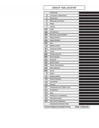
Подборка руководств на английском языке по техническому обслуживанию и ремонту автомобиля Jeep Grand Cherokee в кузове WJ 2000-2001 годов выпуска.
- Автор: —
- Издательство: Chrysler International
- Год издания: —
- Страниц: 2059
- Формат: PDF
- Размер: 187,8 Mb
Руководство на английском языке по техническому обслуживанию и ремонту автомобиля Jeep Grand Cherokee в кузове WK 2005 года выпуска.
- Автор: —
- Издательство: DaimlerChrysler Corporation
- Год издания: —
- Страниц: 7201
- Формат: PDF
- Размер: 81,3 Mb

Руководство по эксплуатации и техническому обслуживанию автомобиля Jeep Grand Cherokee 1999-2004 годов выпуска.
- Автор: —
- Издательство: Монолит
- Год издания: —
- Страниц: 150
- Формат: —
- Размер: —

Руководство по эксплуатации, техническому обслуживанию и ремонту автомобиля Jeep Grand Cherokee 1999-2004 годов выпуска с бензиновыми и дизельными двигателями.
- Автор: —
- Издательство: Автонавигатор
- Год издания: —
- Страниц: 528
- Формат: —
- Размер: —

Руководство по эксплуатации, техническому обслуживанию и ремонту автомобиля Jeep Grand Cherokee 2005-2009 годов выпуска с бензиновыми двигателями.
- Автор: —
- Издательство: Алфамер Паблишинг
- Год издания: —
- Страниц: 312
- Формат: —
- Размер: —

Руководство по техническому обслуживанию и ремонту автомобиля Jeep Grand Cherokee с 1993 года выпуска.
- Автор: —
- Издательство: —
- Год издания: —
- Страниц: 290
- Формат: PDF
- Размер: 124,0 Mb

Руководство по эксплуатации и ремонту автомобиля Jeep Grand Cherokee 1999-2004 годов выпуска с бензиновыми и дизельными двигателями.
- Автор: —
- Издательство: Монолит
- Год издания: —
- Страниц: 266
- Формат: —
- Размер: —

Руководство по эксплуатации и ремонту автомобиля Jeep Grand Cherokee с 2010 года выпуска с бензиновыми и дизельными двигателями.
- Автор: —
- Издательство: Монолит
- Год издания: —
- Страниц: 552
- Формат: —
- Размер: —

Руководство по эксплуатации и техническому обслуживанию автомобиля Jeep Grand Cherokee 2011 года выпуска.
- Автор: —
- Издательство: Chrysler International
- Год издания: 2010
- Страниц: 338
- Формат: PDF
- Размер: 5,5 Mb

Руководство по эксплуатации и техническому обслуживанию автомобиля Jeep Grand Cherokee 2014 года выпуска.
- Автор: —
- Издательство: Chrysler International
- Год издания: —
- Страниц: 372
- Формат: PDF
- Размер: 5,3 Mb

Руководство по эксплуатации, техническому обслуживанию и ремонту автомобиля Jeep Grand Cherokee.
- Автор: Б.У. Звонаревский
- Издательство: Арус
- Год издания: 2004
- Страниц: 279
- Формат: DjVu
- Размер: 16,8 Mb

Мультимедийное руководство по техническому обслуживанию и ремонту автомобиля Jeep Grand Cherokee 1993-1999 годов выпуска.
- Автор: —
- Издательство: —
- Год издания: —
- Страниц: —
- Формат: ISO
- Размер: 87,2 Mb


- Manuals
- Brands
- Jeep Manuals
- Automobile
- GRAND CHEROKEE 2021
- Owner’s manual
-
Contents
-
Table of Contents
-
Bookmarks
Quick Links
2021 GRA ND C H ER OKEE
OWN ER’S MA N UA L
Related Manuals for Jeep GRAND CHEROKEE 2021
Summary of Contents for Jeep GRAND CHEROKEE 2021
-
Page 1
2021 GRA ND C H ER OKEE OWN ER’S MA N UA L… -
Page 2
This Owner’s Manual illustrates and describes the operation of features and equipment that are either standard or optional on this vehicle. This manual may also include a description of features and equipment that are no longer available or were not ordered on this vehicle. -
Page 3: Table Of Contents
TABLE OF CONTENTS INTRODUCTION ……………………..8 GETTING TO KNOW YOUR VEHICLE ………………15 GETTING TO KNOW YOUR INSTRUMENT PANEL …………79 STARTING AND OPERATING ………………..99 MULTIMEDIA ……………………..170 SAFETY ……………………….255 IN CASE OF EMERGENCY ………………..308 SERVICING AND MAINTENANCE ………………329 TECHNICAL SPECIFICATIONS ……………….. 385 CUSTOMER ASSISTANCE …………………
-
Page 4
INTRODUCTION UCONNECT VOICE RECOGNITION ……40 DOORS…………..23 Manual Door Locks……..23 Introducing Voice Recognition….40 Symbols Key…………9 Power Door Locks ……..24 Basic Voice Commands ……41 ROLLOVER WARNING ……….. 9 Keyless Enter-N-Go — Passive Entry ..24 Get Started……….. 41 WARNINGS AND CAUTIONS …….10 Additional Information……… -
Page 5
INTERIOR STORAGE AND EQUIPMENT ….. 62 To Lock/Close The Liftgate ……73 EXTERIOR LIGHTS……….48 Power Liftgate — If Equipped ….. 74 Headlight Switch ……… 48 Storage …………62 Cargo Area Features ……..75 Multifunction Lever ……..49 USB/AUX Control — If Equipped….63 ROOF LUGGAGE RACK —… -
Page 6
STARTING AND OPERATING PARKSENSE FRONT/REAR PARK ASSIST QUADRA-LIFT — IF EQUIPPED……115 Description……….115 SYSTEM — IF EQUIPPED ……..134 STARTING THE ENGINE ……..99 Air Suspension Modes…….117 ParkSense Sensors ……..135 Automatic Transmission……99 Instrument Cluster Display Messages ..117 ParkSense Display……..135 Normal Starting ……….. -
Page 7
TRAILER TOWING ……….151 UCONNECT SETTINGS……..171 CONNECTED SERVICES FAQs ……237 Common Towing Definitions …..151 Customer Programmable Features ..171 Connected Services SOS FAQs ….237 Trailer Hitch Classification ……153 UCONNECT INTRODUCTION ……187 Connected Services Remote Door Lock/ Trailer Towing Weights (Maximum Trailer Unlock FAQs ……….238 System Overview ……..187 Weight Ratings)……….154… -
Page 8
UCONNECT REAR SEAT ENTERTAINMENT OCCUPANT RESTRAINT SYSTEMS ….275 REFUELING IN EMERGENCY – (RSE) SYSTEM — IF EQUIPPED……246 Occupant Restraint Systems Features..275 IF EQUIPPED …………321 Important Safety Precautions….275 Getting Started………..246 IF YOUR ENGINE OVERHEATS ……321 Seat Belt Systems ……..276 Dual Video Screen ……..247 MANUAL PARK RELEASE ……… -
Page 9
STORING THE VEHICLE……..382 VEHICLE MAINTENANCE ……..336 FLUID CAPACITIES……….389 Engine Oil ……….336 BODYWORK …………382 ENGINE FLUIDS AND LUBRICANTS ….390 Engine Oil Filter……….337 Protection From Atmospheric Agents..382 CHASSIS FLUIDS AND LUBRICANTS ….391 Engine Air Cleaner Filter……338 Body And Underbody Maintenance ..382 CUSTOMER ASSISTANCE Air Conditioner Maintenance ….339 Preserving The Bodywork……382… -
Page 10: Introduction
For this reason, it reserves the right to make changes to the model described for technical and/or commercial reasons. For further information, contact an authorized dealer. When it comes to service, remember that authorized dealers know your Jeep vehicle best, have factory-trained technicians and genuine MOPAR® parts, and care about your satisfaction.
-
Page 11: Symbols Key
SYMBOLS KEY ROLLOVER WARNING Utility vehicles have a significantly higher rollover rate than other types of These statements are against vehicles. This vehicle has a higher ground clearance and a higher center of operating procedures that could result gravity than many passenger vehicles. It is capable of performing better in a WARNING! in a collision, bodily injury and/or wide variety of off-road applications.
-
Page 12: Warnings And Cautions
VEHICLE MODIFICATIONS/ALTERATIONS Red Warning Lights WARNING! Door Open Warning Light Ú page 89 Any modifications or alterations to this vehicle could seriously affect its roadworthiness and safety and may lead to a collision resulting in Electric Power Steering (EPS) Fault serious injury or death.
-
Page 13
Yellow Warning Lights Red Warning Lights Service Adaptive Cruise Control Oil Temperature Warning Light (ACC) Warning Light Ú page 90 Ú page 91 Anti-Lock Brake System (ABS) Seat Belt Reminder Warning Light Warning Light Ú page 90 Ú page 91 Transmission Temperature Electronic Stability Control (ESC) Warning Light —… -
Page 14
Yellow Indicator Lights Yellow Warning Lights Air Suspension Active Indicator Low Washer Fluid Warning Light — If Equipped Light — If Equipped Ú page 94 Ú page 92 Air Suspension Entry/Exit Indicator Engine Check/Malfunction Light — If Equipped Indicator Warning Light (MIL) Ú… -
Page 15
Yellow Indicator Lights Green Indicator Lights 4WD Low Indicator Light — If LaneSense Indicator Light — If Equipped Equipped Ú page 95 Ú page 96 NEUTRAL Indicator Light — If Park/Headlight On Indicator Light Equipped Ú page 95 Ú page 95 Snow Mode Indicator Light Green Indicator Lights Ú… -
Page 16
White Indicator Lights Blue Indicator Lights Adaptive Cruise Control (ACC) High Beam Indicator Light Ready Light — If Equipped Ú page 97 Ú page 96 Cruise Control Ready Indicator Light Ú page 96 Hill Descent Control (HDC) Indicator Light — If Equipped Ú… -
Page 17: Getting To Know Your Vehicle
GETTING TO KNOW YOUR VEHICLE KEYS 1 — Unlock Button 2 — Liftgate Button 3 — Emergency Key Your vehicle is equipped with a key fob which 4 — Lock Button supports Passive Entry, Remote Keyless Entry 5 — Remote Start Button (RKE), Keyless Enter-N-Go (if equipped), 6 —…
-
Page 18
GETTING TO KNOW YOUR VEHICLE NOTE: Perchlorate Material — special handling may 2. Separate the key fob halves using a #2 flat apply. See www.dtsc.ca.gov/hazard- blade screwdriver or a coin, and gently pry If the vehicle is unlocked with the key fob, … -
Page 19: Sentry Key
GETTING TO KNOW YOUR VEHICLE 3. Remove the back cover to access and or activated. Operation is automatic, regardless WARNING! replace the battery. When replacing the of whether the vehicle is locked or unlocked. battery, match the (+) sign on the battery to Always remove the key fobs from the …
-
Page 20: Ignition Switch
GETTING TO KNOW YOUR VEHICLE ON/RUN CAUTION! Driving position The Sentry Key Immobilizer system is not All the electrical devices are available (e.g. compatible with some aftermarket remote climate controls, etc.) starting systems. Use of these systems may result in vehicle starting problems and loss of START security protection.
-
Page 21: Remote Start — If Equipped
GETTING TO KNOW YOUR VEHICLE NOTE: WARNING! CAUTION! Obstructions between the vehicle and key fob When exiting the vehicle, always remove An unlocked vehicle is an invitation for may reduce this range. the key fob from the vehicle and lock your thieves.
-
Page 22: To Exit Remote Start Mode
GETTING TO KNOW YOUR VEHICLE To drive the vehicle, push the unlock button, All of the following conditions must be met WARNING! and with a valid Keyless Enter-N-Go key fob in before the engine will Remote Start: the vehicle, press the brake pedal and place the Do not start or run an engine in a closed …
-
Page 23: Remote Start Front Defrost Activation — If Equipped
GETTING TO KNOW YOUR VEHICLE — Once the ignition is placed in the ON/RUN Manual Temperature Control (MTC) — If EMOTE TART OMFORT YSTEMS position, the climate controls will resume the Equipped QUIPPED previously set operations (temperature, blower In ambient temperatures at 40°F (4.5°C) or …
-
Page 24: Remote Start Windshield Wiper De-Icer Activation — If Equipped
GETTING TO KNOW YOUR VEHICLE The instrument cluster display message stays For vehicles equipped with Keyless Entry, EMOTE TART INDSHIELD IPER active until the ignition is placed in the ON/RUN make sure the vehicle’s keyless ignition –I — I CTIVATION QUIPPED position Ú…
-
Page 25: Rearming Of The System
GETTING TO KNOW YOUR VEHICLE NOTE: system will arm, regardless of whether you are AMPER LERT in the vehicle or not. If you remain in the vehicle The driver’s door key cylinder cannot arm or If something has triggered the vehicle security …
-
Page 26: Power Door Locks
GETTING TO KNOW YOUR VEHICLE If the door lock switch is pushed while the OWER OCKS WARNING! ignition is in ACC or ON/RUN and the driver’s The power door lock switches are located on For personal security and safety in the door is open, the doors will not lock.
-
Page 27
GETTING TO KNOW YOUR VEHICLE Passive Entry Unlock initiates illuminated Frequency Operated Button Integrated Key approach (low beams, license plate lamp, (FOBIK-Safe) position lamps) for whichever time duration To minimize the possibility of unintentionally is set between 0, 30 (default), 60 or 90 locking a Passive Entry key fob inside your seconds. -
Page 28
GETTING TO KNOW YOUR VEHICLE When any of these situations occur, after all NOTE: open doors are shut, the FOBIK-Safe search will After pushing the door handle button, you be executed. If it finds a Passive Entry key fob must wait two seconds before you can lock or inside the car, the car will unlock and alert the unlock the doors, using either Passive Entry… -
Page 29: Locking The Doors With One Or More Doors Open
GETTING TO KNOW YOUR VEHICLE — I NOTE: To Lock The Liftgate UTOMATIC OCKS With a valid Passive Entry key fob within 5 ft QUIPPED If the vehicle is unlocked, the liftgate will (1.5 m) of the liftgate, push the Passive Entry open with the handle and no key fob is The auto door lock feature default condition is lock button located on the outside liftgate door…
-
Page 30: Steering Wheel
GETTING TO KNOW YOUR VEHICLE STEERING WHEEL For emergency exit with the system engaged, pull up on the door lock knob (unlocked posi- tion), roll down the window, and open the ANUAL ELESCOPING TEERING door with the outside door handle. —…
-
Page 31: Power Tilt/Telescoping Steering
GETTING TO KNOW YOUR VEHICLE — I the steering column, pull the steering wheel EATED TEERING HEEL outward or push it inward as desired. To lock QUIPPED the steering column in position, push the The steering wheel contains a heating element control upward until fully engaged.
-
Page 32: Driver Memory Settings — If Equipped
GETTING TO KNOW YOUR VEHICLE Power tilt and telescopic steering column (if ROGRAMMING EMORY EATURE WARNING! equipped) To create a new memory profile, perform the Persons who are unable to feel pain to the A set of desired radio station presets following: …
-
Page 33: Linking And Unlinking The Key Fob To
GETTING TO KNOW YOUR VEHICLE SEATS NOTE: INKING NLINKING Your key fob can be unlinked to your memory EMORY Seats are a part of the Occupant Restraint settings by pushing the set (S) button, followed System of the vehicle. Your key fobs can be programmed to recall one by pushing the unlock button on the key fob of two saved memory profiles by pushing the within 10 seconds.
-
Page 34: Manual Adjustment (Front Seats) — If
GETTING TO KNOW YOUR VEHICLE ANUAL DJUSTMENT RONT EATS WARNING! (Continued) — I QUIPPED Seats should be adjusted before fastening the seat belts and while the vehicle is WARNING! parked. Serious injury or death could result Adjusting a seat while the vehicle is moving from a poorly adjusted seat belt.
-
Page 35: Manual Adjustment (Rear Seats)
GETTING TO KNOW YOUR VEHICLE ANUAL DJUSTMENT EATS WARNING! WARNING! Do not ride with the seatback reclined so that Adjusting a seat while the vehicle is moving WARNING! is dangerous. The sudden movement of the the shoulder belt is no longer resting against Do not pile luggage or cargo higher than the your chest.
-
Page 36
GETTING TO KNOW YOUR VEHICLE NOTE: To Raise Rear Seat WARNING! Do not fold the 60% rear seat down with the Raise the rear seatback and lock it into place. If Do not ride with the seatback reclined so that left outboard or rear center seat belt buckled. -
Page 37: Power Adjustment (Front Seats) — If Equipped
GETTING TO KNOW YOUR VEHICLE ) — Adjusting The Seat Up Or Down OWER DJUSTMENT RONT EATS WARNING! (Continued) The height of the seats can be adjusted up or QUIPPED Seats should be adjusted before fastening down by using the power seat switch. The seat Some models may be equipped with eight-way the seat belts and while the vehicle is will move in the direction of the switch.
-
Page 38: Heated Seats — If Equipped
GETTING TO KNOW YOUR VEHICLE — I the lumbar support. Pushing upward or When you place the vehicle’s ignition in the EATED EATS QUIPPED OFF position, the driver seat will move about downward on the switch will raise and lower the position of the support.
-
Page 39: Front Ventilated Seats — If Equipped
GETTING TO KNOW YOUR VEHICLE — I Front Heated Seats — If Equipped Rear Heated Seats — If Equipped RONT ENTILATED EATS The front heated seats control buttons are On some models, the two rear outboard seats QUIPPED located within the Uconnect system. You can may be equipped with heated seats.
-
Page 40: Head Restraints
GETTING TO KNOW YOUR VEHICLE head restraint. The AHRs will be split in two For comfort, the Active Head Restraints can be ESTRAINTS halves, with the front half being soft foam and tilted forward and rearward. To tilt the head Head restraints are designed to reduce the risk trim, the back half being decorative plastic.
-
Page 41
GETTING TO KNOW YOUR VEHICLE NOTE: WARNING! (Continued) The head restraints should only be removed Active Head Restraints may be deployed if by qualified technicians, for service purposes they are struck by an object such as a hand, only. -
Page 42: Uconnect Voice Recognition
GETTING TO KNOW YOUR VEHICLE NOTE: WARNING! For proper routing of a Child Seat Tether, see ALL the head restraints MUST be rein- Ú page 275. stalled in the vehicle to properly protect the occupants. Follow the re-installation WARNING! instructions above prior to operating the A loose head restraint thrown forward in a …
-
Page 43: Basic Voice Commands
GETTING TO KNOW YOUR VEHICLE Each time you give a Voice Command, you ASIC OICE OMMANDS DDITIONAL NFORMATION must first push the Voice Recognition (VR) The basic Voice Commands below can be given © 2020 FCA US LLC. All rights reserved. Mopar button, wait until after the beep, then say at any point while using your Uconnect system.
-
Page 44: Mirrors
GETTING TO KNOW YOUR VEHICLE MIRRORS Automatic Dimming Mirror — If Equipped CAUTION! The rearview mirror can be adjusted up, down, To avoid damage to the mirror during NSIDE EARVIEW IRROR left, and right. The mirror should be adjusted to cleaning, never spray any cleaning solution center on the view through the rear window.
-
Page 45: Outside Mirrors
GETTING TO KNOW YOUR VEHICLE Sun Visor “Slide-On-Rod” Feature — If OWER IRRORS WARNING! Equipped The power mirror switch is located on the Vehicles and other objects seen in an outside The sun visor “Slide-On-Rod” feature allows for driver’s side door trim panel. convex mirror will look smaller and farther additional flexibility in positioning the sun visor The power mirror controls consist of mirror…
-
Page 46: Power Folding Outside Mirrors
GETTING TO KNOW YOUR VEHICLE — Automatic Power Folding Mirrors The mirrors come out of the unfolded posi- OWER OLDING UTSIDE IRRORS tion. QUIPPED When the Automatic Fold Mirrors feature is enabled, the exterior mirrors will fold in when The mirrors shake and vibrate at normal …
-
Page 47: Universal Garage Door Opener
GETTING TO KNOW YOUR VEHICLE ® REVERSE. If the vehicle is equipped with The HomeLink® buttons that are located in RASING memory settings, this feature will be linked to the overhead console or sunvisor designate HANNELS the three different HomeLink® channels. the programmable settings.
-
Page 48: Programming Homelink® To A Garage Door Opener
GETTING TO KNOW YOUR VEHICLE Rolling Code Devices NOTE: Rolling Code Garage Door Opener Final Steps All HomeLink® buttons are programmed using To determine if your device has a rolling code, a NOTE: this procedure. You do not need to erase all good indicator is its manufacturing date.
-
Page 49: Miscellaneous Device
GETTING TO KNOW YOUR VEHICLE ® T Non-Rolling Code Garage Door Opener Final 1. Place the ignition in the ON/RUN position, ROGRAMMING Steps without starting the engine. ISCELLANEOUS EVICE 1. Push and hold the programmed 2. Push and hold the desired HomeLink® Follow the procedure on programming HomeLink®…
-
Page 50: Reprogramming A Single Homelink
GETTING TO KNOW YOUR VEHICLE EXTERIOR LIGHTS It may be helpful to unplug the device during the NOTE: cycling process to prevent possible overheating If the indicator light stays on constantly, of the garage door or gate motor. EADLIGHT WITCH programming is complete and the garage door/device should activate when the…
-
Page 51: Multifunction Lever
GETTING TO KNOW YOUR VEHICLE To turn on the headlights, rotate the headlight Once the turn signal is no longer active, the ULTIFUNCTION EVER switch clockwise. When the headlight switch is DRL lamp will illuminate. The multifunction lever is located on the left on, the parking lights, taillights, license plate The DRLs function may be disabled through side of the steering column.
-
Page 52: Flash-To-Pass
GETTING TO KNOW YOUR VEHICLE — I NOTE: UTOMATIC EADLIGHTS QUIPPED UTOMATIC EADLIGHTS IPERS The Automatic High Beam Headlamp Control This system automatically turns the headlights If your vehicle is equipped with Automatic can be turned on or off by selecting “ON” on or off according to ambient light levels.
-
Page 53: Headlight Delay
GETTING TO KNOW YOUR VEHICLE — I EADLIGHT ELAY IGHTS QUIPPED IGNALS To assist when exiting the vehicle, the headlight The fog lights are turned on by rotating the Move the multifunction lever up or down to delay feature will leave the headlights on for up headlight switch to the parking light or headlight activate the turn signals.
-
Page 54: Battery Saver
GETTING TO KNOW YOUR VEHICLE are on, rotating the dimmer control all the way ATTERY AVER down, to the last (off) detent, will cause all the Timers are set to both the interior and exterior interior lights to turn off. This is also known as lights to protect the life of your vehicle’s battery.
-
Page 55: Windshield Wipers And Washers
GETTING TO KNOW YOUR VEHICLE Ambient Light — If Equipped click. This feature is called “Parade” mode and is useful when headlights are required during The overhead console is equipped with an the day. Rotating the dimmer control up to the ambient light feature.
-
Page 56: Rain Sensing Wipers — If Equipped
GETTING TO KNOW YOUR VEHICLE Mist CAUTION! Rotate the end of the lever downward to the Always remove any buildup of snow that MIST position and release for a single wiping prevents the windshield wiper blades from cycle. returning to the “park” position. If the NOTE: windshield wiper switch is turned off, and the The Mist feature does not activate the washer…
-
Page 57: Rear Window Wiper/Washer
GETTING TO KNOW YOUR VEHICLE NOTE: Sensing system will not operate until the Rotate the center portion of the lever wiper switch is moved, vehicle speed is upward to the first detent for The Rain Sensing feature will not operate …
-
Page 58: Climate Controls
GETTING TO KNOW YOUR VEHICLE CLIMATE CONTROLS A/C Button Press and release this button on the The Climate Control system allows you to touchscreen, or push the button on regulate the temperature, air flow, and direction the faceplate to change the current of air circulating throughout the vehicle.
-
Page 59
GETTING TO KNOW YOUR VEHICLE Recirculation Button AUTO Button Rear Defrost Button Press and release this button on the Press and release this button on the Press and release the button on the touchscreen, or push the button on touchscreen, or push the button on touchscreen, or push and release the the faceplate to change the system the faceplate, to change the current… -
Page 60
GETTING TO KNOW YOUR VEHICLE Driver And Passenger Up And Down Blower Control The airflow distribution mode can be adjusted so air comes from the instrument panel outlets, Buttons Blower Control is used to regulate the floor outlets, defrost outlets and demist outlets. amount of air forced through the These buttons provide the driver and passenger Climate Control system. -
Page 61: Automatic Temperature Control (Atc)
GETTING TO KNOW YOUR VEHICLE Floor Mode NOTE: UTOMATIC EMPERATURE ONTROL (ATC) Air comes from the floor outlets. A It is not necessary to move the temperature slight amount of air is directed settings for cold or hot vehicles. The system Automatic Operation through the defrost and side window automatically adjusts the temperature,…
-
Page 62: Climate Voice Commands
GETTING TO KNOW YOUR VEHICLE against engine overheating. OAT coolant Outside Air Intake LIMATE OICE OMMANDS (conforming to MS.90032) is recommended. Make sure the air intake, located directly in Adjust vehicle temperatures hands-free and front of the windshield, is free of obstructions, Winter Operation keep everyone comfortable while you keep such as leaves.
-
Page 63
GETTING TO KNOW YOUR VEHICLE Windshield Wiper De-Icer — If Equipped Operating Tips Chart CONTROL WEATHER The windshield wiper de-icer is a heating SETTINGS NOTE: element located at the base of the windshield. The below chart is for Manual Override Opera- Set the mode control It operates automatically once the following tion, otherwise run in AUTO. -
Page 64: Interior Storage And Equipment
GETTING TO KNOW YOUR VEHICLE INTERIOR STORAGE AND EQUIPMENT To open the upper storage compartment, pull WARNING! upward on the small latch located on the lid. Do not operate this vehicle with a glove TORAGE Lift upward on the larger of the latches to compartment in the open position.
-
Page 65: Usb/Aux Control — If Equipped
GETTING TO KNOW YOUR VEHICLE Overhead Console The overhead console contains courtesy/ reading lights and storage for sunglasses. Universal Garage Door Opener (HomeLink®), power liftgate and power sunroof/sunshade switches may also be included, if equipped. Sunglasses Bin Door Integrated Center Console USB/AUX Media HUB 1 —…
-
Page 66: Power Outlets
GETTING TO KNOW YOUR VEHICLE the USB control system can charge it to the off when the vehicle is not in use to protect the required level. battery against discharge. Using This Feature CAUTION! By using an external USB device to connect to Power outlets are designed for accessory the USB port: plugs only.
-
Page 67
GETTING TO KNOW YOUR VEHICLE In addition to the front power outlet, there is NOTE: also a power outlet located in the storage area The rear power outlet can be switched from of the center console. “ignition” only to constant “battery” powered all the time. -
Page 68: Power Inverter — If Equipped
GETTING TO KNOW YOUR VEHICLE — I The power inverter is designed with built-in OWER NVERTER QUIPPED WARNING! (Continued) overload protection. If the power rating of There is a 115 Volt, 150 Watt inverter outlet 150 Watts is exceeded, the power inverter will Close the lid when not in use and while …
-
Page 69: Windows
GETTING TO KNOW YOUR VEHICLE WINDOWS If equipped, the key fob may also be used to UTOMATIC INDOW EATURES raise or lower vehicle windows while the ignition Auto-Down Feature OWER INDOW ONTROLS is in the OFF position. The driver and front passenger door power The window controls on the driver’s door control NOTE: window switches have an Auto-Down feature.
-
Page 70: Reset Auto-Up
GETTING TO KNOW YOUR VEHICLE NOTE: open or partially open positions. This is a normal INDOW OCKOUT WITCH Any impact due to rough road conditions may occurrence and can be minimized. If the The window lockout switch on the driver’s door trigger the auto-reverse function unexpectedly buffeting occurs with the rear windows open, trim panel allows you to disable the window…
-
Page 71: Opening And Closing The Sunroof
GETTING TO KNOW YOUR VEHICLE PENING LOSING UNROOF INCH ROTECT EATURE WARNING! Express Open/Close This feature will detect an obstruction in the Never leave children unattended in a closing of the sunroof during the Express Close vehicle, or with access to an unlocked Push the switch rearward and release it within operation.
-
Page 72: Sunshade Operation
GETTING TO KNOW YOUR VEHICLE UNSHADE PERATION WARNING! (Continued) The sunshade can be opened manually. In a collision, there is a greater risk of being However, the sunshade will open automatically thrown from a vehicle with an open sunroof. as the sunroof opens.
-
Page 73: Opening And Closing The Power
GETTING TO KNOW YOUR VEHICLE Push the switch forward and release it within Push the sunshade switch forward and release PENING LOSING OWER one-half second and the sunroof will close it within one-half second and the sunshade will UNSHADE automatically from any position. The sunroof close automatically.
-
Page 74: Pinch Protect Feature
GETTING TO KNOW YOUR VEHICLE INCH ROTECT EATURE UNROOF AINTENANCE This feature will detect an obstruction in the Use only a non-abrasive cleaner and a soft cloth opening of the sunroof during Express Close to clean the glass panel. Periodically check for operation.
-
Page 75: Liftgate
GETTING TO KNOW YOUR VEHICLE NOTE: CAUTION! WARNING! If “Unlock All Doors 1st Press” is programmed in To prevent possible damage, do not slam the Uconnect, all doors will unlock when you push Driving with the liftgate open can allow the electronic liftgate release handle.
-
Page 76: Power Liftgate — If Equipped
GETTING TO KNOW YOUR VEHICLE — I open, the liftgate can be closed by pushing the OWER IFTGATE QUIPPED WARNING! liftgate button located on the left rear trim The power liftgate may be opened by panel. If the liftgate is in motion, pushing the During power operation, personal injury or pushing the electronic liftgate release button again will reverse the liftgate.
-
Page 77: Cargo Area Features
GETTING TO KNOW YOUR VEHICLE If the liftgate is only partially open, push the NOTE: liftgate button on the key fob twice to operate If your vehicle is equipped with a rear the liftgate. subwoofer, the storage bin on that side will not be available.
-
Page 78
GETTING TO KNOW YOUR VEHICLE Retractable Cargo Area Cover — If WARNING! WARNING! Equipped In a collision, a loose cargo cover in the To help protect against personal injury, The purpose of this cover is for privacy, not to passengers should not be seated in the vehicle could cause injury. -
Page 79: Roof Luggage Rack — If Equipped
GETTING TO KNOW YOUR VEHICLE sure the total load of cargo inside the vehicle WARNING! WARNING! (Continued) plus that on the external rack does not exceed the maximum vehicle load capacity. Cargo must be securely tied down before Place as much cargo as possible in front of …
-
Page 80
GETTING TO KNOW YOUR VEHICLE CAUTION! (Continued) Long loads which extend over the wind- shield, such as wood panels or surfboards, or loads with large frontal area should be secured to both the front and rear of the vehicle. Place a blanket or other protection … -
Page 81: Getting To Know Your Instrument Panel
GETTING TO KNOW YOUR INSTRUMENT PANEL INSTRUMENT CLUSTER — GASOLINE Gasoline Instrument Cluster…
-
Page 82: Instrument Cluster Descriptions
GETTING TO KNOW YOUR INSTRUMENT PANEL NSTRUMENT LUSTER ESCRIPTIONS CAUTION! 1. Tachometer Driving with a hot engine cooling system Indicates the engine speed in revolutions could damage your vehicle. If the per minute (RPM x 1000). temperature gauge reads “H” pull over and stop the vehicle.
-
Page 83: Instrument Cluster Display Location And Controls
GETTING TO KNOW YOUR INSTRUMENT PANEL 3. The main display area where the menus and NSTRUMENT LUSTER ISPLAY pop up messages are displayed. OCATION ONTROLS 4. The lower line where reconfigurable The instrument cluster display is located in the telltales, menu name and menu page are center of the instrument cluster.
-
Page 84: Oil Change Reset — If Equipped
GETTING TO KNOW YOUR INSTRUMENT PANEL The system allows the driver to select NOTE: scheduled oil change interval. The engine oil information by pushing the following buttons change indicator system is duty cycle based, Holding the up / down or left / right …
-
Page 85: Instrument Cluster Display Menu Items
GETTING TO KNOW YOUR INSTRUMENT PANEL Secondary Method For Oil Change Reset NOTE: NON — SRT Procedure Depending on the vehicle’s options, feature Tire Pressure Oil Pressure settings may vary. 1. Without pushing the brake pedal, place the Transmission Oil Life …
-
Page 86
GETTING TO KNOW YOUR INSTRUMENT PANEL Drivetrain: Displays information on drivetrain Adaptive Cruise Control Ready NOTE: status of Front Wheel Angle, T-Case, and Axle The instrument cluster display will return to the When ACC is activated but the vehicle speed Lock. -
Page 87
GETTING TO KNOW YOUR INSTRUMENT PANEL message. Adding a significant amount of fuel Average Fuel Economy – Shows the average Screen Setup to the vehicle will turn off the “RANGE LOW” fuel economy (MPG or L/100 km or km/L) of Push and release the up or down arrow… -
Page 88: Battery Saver On/Battery Saver Mode Message — Electrical Load Reduction Actions (If Equipped)
GETTING TO KNOW YOUR INSTRUMENT PANEL Fuel Economy Current Current Gear ATTERY AVER ATTERY AVER — E ESSAGE LECTRICAL Trip A EDUCTION CTIONS QUIPPED Trip B This vehicle is equipped with an Intelligent Favorite Menus Upper Right Battery Sensor (IBS) to perform additional Speedometer…
-
Page 89
GETTING TO KNOW YOUR INSTRUMENT PANEL NOTE: Turning on all possible vehicle electrical What to do when an electrical load reduction loads (e.g. HVAC to max settings, exterior and action message is present (“Battery Saver On” The charging system is independent from … -
Page 90: Trip Computer
GETTING TO KNOW YOUR INSTRUMENT PANEL TRIP COMPUTER precautionary and as such must not be the brake light turns on it may indicate that the considered as exhaustive. Always refer to the parking brake is applied, that the brake fluid Push and release the up or down arrow…
-
Page 91
GETTING TO KNOW YOUR INSTRUMENT PANEL NOTE: detected. If the light does not illuminate, have Electric Power Steering (EPS) Fault The light may flash momentarily during sharp the light inspected by an authorized dealer. Warning Light cornering maneuvers, which change fluid level The light also will turn on when the parking This warning light will turn on when conditions. -
Page 92
GETTING TO KNOW YOUR INSTRUMENT PANEL NOTE: transmission into NEUTRAL (N) and idle the Do not operate the vehicle until the cause is This light may turn on if the accelerator and vehicle. If the temperature reading does not corrected. This light does not indicate how brake pedals are pressed at the same time. -
Page 93: Yellow Warning Lights
GETTING TO KNOW YOUR INSTRUMENT PANEL Transmission Temperature Warning Light Vehicle Security Warning Light — If conventional brake system will continue to operate normally, assuming the Brake Warning — If Equipped Equipped Light is not also on. This warning light will illuminate to This light will flash at a fast rate for warn of a high transmission fluid approximately 15 seconds when the…
-
Page 94
GETTING TO KNOW YOUR INSTRUMENT PANEL The ESC OFF Indicator Light and the ESC Indi- LaneSense Warning Light — If Equipped Engine Check/Malfunction Indicator cator Light come on momentarily each time Warning Light (MIL) The LaneSense Warning Light will be the ignition is placed in the ON/RUN or ACC/ solid yellow when the vehicle is The Engine Check/Malfunction… -
Page 95
GETTING TO KNOW YOUR INSTRUMENT PANEL nearest service center and have the vehicle Should one or more tires be in the condition WARNING! serviced immediately. mentioned above, the display will show the A malfunctioning catalytic converter, as indications corresponding to each tire. Service Forward Collision Warning (FCW) referenced above, can reach higher Light —… -
Page 96: Yellow Indicator Lights
GETTING TO KNOW YOUR INSTRUMENT PANEL tires as soon as possible, and inflate them to installation of replacement or alternate tires or ELLOW NDICATOR IGHTS the proper pressure. Driving on a significantly wheels on the vehicle that prevent the TPMS Air Suspension Active Indicator Light —…
-
Page 97: Green Indicator Lights
GETTING TO KNOW YOUR INSTRUMENT PANEL Air Suspension Off-Road 2 Indicator Light LaneSense Indicator Light — If Equipped REEN NDICATOR IGHTS — If Equipped The LaneSense indicator light Adaptive Cruise Control (ACC) Set With No illuminates solid green when both This light will illuminate when the air Target Detected Indicator Light —…
-
Page 98: White Indicator Lights
GETTING TO KNOW YOUR INSTRUMENT PANEL Tow Mode Indicator Light LaneSense Indicator Light — If Equipped HITE NDICATOR IGHTS This light will turn on when Tow Mode When the LaneSense system is ON, Adaptive Cruise Control (ACC) Ready Light is active. but not armed, the LaneSense —…
-
Page 99: Blue Indicator Lights
GETTING TO KNOW YOUR INSTRUMENT PANEL and other information to assist your service NDICATOR IGHTS WARNING! technician in making repairs. Although your High Beam Indicator Light vehicle will usually be drivable and not need ONLY an authorized service technician towing, see an authorized dealer for service as should connect equipment to the OBD II This indicator light will illuminate to…
-
Page 100: Emissions Inspection And Maintenance
GETTING TO KNOW YOUR INSTRUMENT PANEL EMISSIONS INSPECTION AND 1. Switch the ignition to the ON position, but If your OBD II system is not ready, you should do not crank or start the engine. see an authorized dealer or repair facility. If your MAINTENANCE PROGRAMS vehicle was recently serviced or had a battery NOTE:…
-
Page 101: Starting And Operating
STARTING AND OPERATING STARTING THE ENGINE WARNING! (Continued) CAUTION! Before starting your vehicle, adjust your seat, Damage to the transmission may occur if the Do not leave the key fob in or near the adjust the inside and outside mirrors, fasten vehicle, or in a location accessible to chil- following precautions are not observed: your seat belt, and if present, instruct all other…
-
Page 102: Autopark
STARTING AND OPERATING 3. The system starts the vehicle. If the vehicle 4. If the vehicle speed is above 5 mph (8 km/h), 3. Push the ENGINE START/STOP button a fails to start, the starter will disengage the ENGINE START/STOP button must be second time to place the ignition to the RUN automatically after 10 seconds.
-
Page 103
STARTING AND OPERATING Vehicle speed is 1.2 mph (1.9 km/h) or less NOTE: WARNING! In some cases the ParkSense graphic will be Ignition switched from RUN to ACC Driver inattention could lead to failure to displayed in the instrument cluster. In these … -
Page 104: If Engine Fails To Start
STARTING AND OPERATING 4WD LOW — If Equipped 15 seconds. This should clear any excess fuel in CAUTION! case the engine is flooded. Leave the ignition AutoPark will be disabled when operating the key in the RUN position, release the accelerator To prevent damage to the starter, do not vehicle in 4WD LOW.
-
Page 105: Engine Break-In Recommendations
STARTING AND OPERATING PARKING BRAKE The engine block heater must be plugged in at While cruising, brief full-throttle acceleration least one hour to have an adequate warming within the limits of local traffic laws contributes Before leaving the vehicle, make sure that the effect on the engine.
-
Page 106
STARTING AND OPERATING NOTE: WARNING! (Continued) WARNING! (Continued) When the parking brake is applied and the When leaving the vehicle, always remove Be sure the parking brake is fully disen- transmission is placed in gear, the Brake the key fob from the ignition and lock your gaged before driving;… -
Page 107: Automatic Transmission
STARTING AND OPERATING AUTOMATIC TRANSMISSION WARNING! (Continued) WARNING! (Continued) You must press and hold the brake pedal while It is dangerous to shift out of PARK or Never leave children alone in a vehicle, or shifting out of PARK. NEUTRAL if the engine speed is higher than with access to an unlocked vehicle.
-
Page 108: Ignition Park Interlock
STARTING AND OPERATING When the Fuel Economy (ECO) Mode is RAKE RANSMISSION HIFT CAUTION! (Continued) engaged, the vehicle control systems will (BTSI) S NTERLOCK YSTEM change the following: Do not shift between PARK, REVERSE, This vehicle is equipped with a BTSI system that NEUTRAL, or DRIVE when the engine is The transmission will upshift sooner and …
-
Page 109: Eight-Speed Automatic Transmission
STARTING AND OPERATING –S continuously until the selector is returned to IGHT PEED UTOMATIC the proper position, or the requested shift RANSMISSION can be completed. The transmission gear range is displayed both The electronically-controlled transmission beside the gear selector and in the instrument adapts its shift schedule based on driver inputs, cluster.
-
Page 110
STARTING AND OPERATING Gear Ranges When exiting the vehicle, always: WARNING! (Continued) Do not press the accelerator pedal when Apply the parking brake The transmission may not engage PARK if shifting out of PARK or NEUTRAL. Shift the transmission into PARK the vehicle is moving. -
Page 111
STARTING AND OPERATING Look at the transmission gear position WARNING! (Continued) WARNING! (Continued) display and verify that it indicates the PARK position (P), and is not blinking. Unintended movement of a vehicle could Do not leave the key fob in or near the … -
Page 112
STARTING AND OPERATING During extremely cold temperatures (-22°F be severely degraded and the engine may stall. CAUTION! [-30°C] or below), transmission operation may In some situations, the transmission may not Towing the vehicle, coasting, or driving for any be modified depending on engine and re-engage if the engine is turned off and other reason with the transmission in transmission temperature as well as vehicle… -
Page 113
STARTING AND OPERATING 5. Restart the engine. AutoStick mode has the following operational benefits: 6. Shift into the desired gear range. If the The transmission will automatically down- problem is no longer detected, the shift as the vehicle slows (to prevent engine transmission will return to normal lugging) and will display the current gear. -
Page 114: Sport Mode — If Equipped
STARTING AND OPERATING SPORT MODE — IF EQUIPPED FOUR WHEEL DRIVE OPERATION Transmission shifting will be more noticeable when AutoStick is enabled. UADRA PERATING The system may revert to automatic shift — I NSTRUCTIONS RECAUTIONS mode if a fault or overheat condition is detected.
-
Page 115: Quadra-Trac Ii Operating Instructions
STARTING AND OPERATING II O Proper operation of four-wheel drive vehicles UADRA PERATING HIFT OSITIONS depends on tires of equal size, type, and — I NSTRUCTIONS RECAUTIONS For additional information on the appropriate circumference on each wheel. Any difference QUIPPED use of each 4WD system mode position, see the will adversely affect shifting and cause damage information below:…
-
Page 116: Shifting Procedures
STARTING AND OPERATING 4WD LOW NOTE: teeth not being properly aligned. Several attempts may be required for clutch teeth If shift conditions/interlocks are not met, or a This range is for low speed four-wheel drive. It transfer case motor temperature protection alignment and shift completion to occur.
-
Page 117: Quadra-Lift — If Equipped
STARTING AND OPERATING QUADRA-LIFT — IF EQUIPPED Normal Ride Height (NRH) – This is the stan- dard position of the suspension and is meant for normal driving. ESCRIPTION The Quadra-Lift air suspension system provides Off-Road 1 (OR1) (Raises the vehicle approx- …
-
Page 118
STARTING AND OPERATING Aero Mode (Lowers the vehicle approximately speed exceeds 25 mph (40 km/h) the Entry/ The system requires that the engine be running 0.6 inches (15 mm)) – This position provides Exit Mode change will be canceled. To exit for all changes. -
Page 119: Air Suspension Modes
STARTING AND OPERATING Auto Entry/Exit Mode Wheel Alignment Mode WARNING! To assist in entering and exiting the vehicle, the Before performing a wheel alignment this mode The air suspension system uses a high air suspension system has a feature which must be enabled Ú…
-
Page 120
STARTING AND OPERATING indicators are flashing on the «DOWN» button Automatic height changes will occur based on turn off and indicator lamp 5 will flash until the lowest solid indicator lamp is the position vehicle speed and the current vehicle height. Entry/Exit Mode is achieved at which point the system is working to achieve. -
Page 121: Selec-Terrain — If Equipped
STARTING AND OPERATING SELEC-TERRAIN — IF EQUIPPED equipped with air suspension, the default ROCK – Off-road calibration is only available ride height for SNOW is Normal Ride Height in 4WD LOW range. The vehicle is raised (if (NRH). equipped with Air Suspension) for improved ELEC ERRAIN ELECTION…
-
Page 122: Fuel Saver Technology 5.7L Only — If
STARTING AND OPERATING FUEL SAVER TECHNOLOGY 5.7L ONLY — IF STOP/START SYSTEM — IF EQUIPPED If the Electric Power Steering warning icon is displayed and the “SERVICE EQUIPPED The Stop/Start function is developed to reduce POWER STEERING” or the “POWER fuel consumption.
-
Page 123: Possible Reasons The Engine Does Not Autostop
STARTING AND OPERATING The engine will shut down, the tachometer will HVAC is set to full defrost mode at a high Gear selector in MANUAL (M) mode. move to the zero position and the Stop/Start blower speed. Stop/Start related system malfunction. …
-
Page 124: To Manually Turn Off The Stop/Start System
STARTING AND OPERATING CRUISE CONTROL SYSTEMS — IF EQUIPPED Battery voltage drops too low. NOTE: The Stop/Start system will reset itself back to Stop/Start OFF switch is pushed. The Cruise Control system has two control an ON condition every time the ignition is turned modes that function differently.
-
Page 125
STARTING AND OPERATING To Set A Desired Speed WARNING! Turn the Cruise Control on. When the vehicle Cruise Control can be dangerous where the has reached the desired speed, push and system cannot maintain a constant speed. release the SET (+) or SET (-) button. Release Your vehicle could go too fast for the the accelerator and the vehicle will operate at conditions, and you could lose control and… -
Page 126: Adaptive Cruise Control (Acc)
STARTING AND OPERATING Metric Speed (km/h) The following conditions will also deactivate the WARNING! Cruise Control without erasing the set speed Pushing the SET (+), or SET (-) button once Cruise Control can be dangerous where the from memory: will result in a 1 km/h speed adjustment.
-
Page 127
STARTING AND OPERATING NOTE: WARNING! WARNING! (Continued) If the ACC sensor detects a vehicle ahead, Adaptive Cruise Control (ACC) is a conve- Will bring the vehicle to a complete stop ACC will apply limited braking or accelerate nience system. -
Page 128
STARTING AND OPERATING Adaptive Cruise Control (ACC) Operation Adaptive Cruise Control (ACC) Menu The ACC screen may display once again if any of the following ACC activity occurs: The Cruise Control buttons (located on the right The instrument cluster display shows the side of the steering wheel) operate the ACC current ACC system settings. -
Page 129
STARTING AND OPERATING NOTE: the instrument cluster displays “Adaptive Cruise WARNING! You cannot engage ACC under the following Control (ACC) Off.” conditions: In the Fixed Speed Cruise Control mode, the WARNING! system will not react to vehicles ahead. In When in 4WD Low … -
Page 130
STARTING AND OPERATING NOTE: The Trailer Sway Control (TSC) activates Resume can be used at any speed above 20 mph (32 km/h) when only Fixed Speed The driver switches ESC to Full Off mode Keeping your foot on the accelerator pedal … -
Page 131
STARTING AND OPERATING To Vary The Speed Setting NOTE: Setting The Following Distance In ACC When you override and push the SET (+) button To Increase Or Decrease The Set Speed The specified following distance for ACC can be or SET (-) buttons, the new set speed will be the set by varying the distance setting between four While ACC is set, you can increase speed by current speed of the vehicle. -
Page 132
STARTING AND OPERATING To decrease the distance setting, push the NOTE: ACC Operation At Stop Distance Decrease button and release. Each The brake lights will illuminate whenever the If the ACC system brings your vehicle to a time the button is pushed, the distance setting ACC system applies the brakes. -
Page 133
STARTING AND OPERATING Display Warnings And Maintenance If weather conditions are not a factor, the driver NOTE: should examine the sensor. It may require If the “ACC/FCW Unavailable Wipe Front “Wipe Front Radar Sensor In Front Of Vehicle” cleaning or removal of an obstruction. The Radar Sensor”… -
Page 134
STARTING AND OPERATING This message can sometimes be displayed Service ACC/FCW Warning Offset Driving while driving in adverse weather conditions. The If the system turns off, and the instrument ACC may not detect a vehicle in the same lane ACC/FCW system will recover after the vehicle cluster displays “ACC/FCW Unavailable Service that is offset from your direct line of travel, or a has left these areas. -
Page 135
STARTING AND OPERATING Turns And Bends When driving on a curve with ACC engaged, the system may increase or decrease the vehicle speed for stability, with no vehicle ahead detected. Once the vehicle is out of the curve the system will resume your original set speed. This is a part of normal ACC system functionality. -
Page 136: Parksense Front/Rear Park Assist
STARTING AND OPERATING Stationary Objects And Vehicles automatically applied and released when The automatic braking function may not be applied fast enough for obstacles that move performing a reverse parking maneuver if the ACC does not react to stationary objects and system detects a possible collision with an toward the rear of the vehicle from the left stationary vehicles.
-
Page 137: Parksense Sensors
STARTING AND OPERATING ParkSense will retain the last system state ENSE ENSORS ENSE ISPLAY (enabled or disabled) from the last ignition cycle The six ParkSense sensors (four when vehicle is The warning display will turn on indicating the when the ignition is changed to the ON/RUN not equipped with front sensors), located in the system status when the vehicle is in REVERSE position.
-
Page 138
STARTING AND OPERATING Front/Rear ParkSense Arcs 1 — No Tone/Solid Arc 6 — Fast Tone/Flashing Arc 2 — No Tone/Flashing Arc 7 — Fast Tone/Flashing Arc 3 — Fast Tone/Flashing Arc 8 — Slow Tone/Solid Arc 4 — Continuous Tone/Flashing Arc 9 —… -
Page 139
STARTING AND OPERATING The vehicle is close to the obstacle when the instrument cluster display shows one flashing arc and sounds a continuous tone. The following chart shows the warning alert operation when the system is detecting an obstacle: WARNING ALERTS FOR REAR Greater than Less than 79-59 inches… -
Page 140: Parksense Warning Display
STARTING AND OPERATING Front Park Assist Audible Alerts NABLING ISABLING ENSE ERVICE ENSE SSIST YSTEM ParkSense will turn off the Front Park Assist ParkSense can be enabled and disabled with audible alert (chime) after approximately three the ParkSense switch. During vehicle start up, when the ParkSense seconds when an obstacle has been detected, System has detected a faulted condition, the When the ParkSense switch is pushed…
-
Page 141: Cleaning The Parksense System
STARTING AND OPERATING UNAVAILABLE SERVICE REQUIRED» messages if Clean the ParkSense sensors regularly, ENSE YSTEM SAGE an object is detected within the five second taking care not to scratch or damage them. RECAUTIONS The sensors must not be covered with ice, pop-up duration.
-
Page 142: Parksense Active Park Assist System — If Equipped
STARTING AND OPERATING Active Park Assist system is capable of WARNING! CAUTION! maneuvering a vehicle into a parallel or a Drivers must be careful when backing up ParkSense is only a parking aid and it is perpendicular parking space on either side (i.e., …
-
Page 143: Enabling And Disabling The Parksense Active Park Assist System
STARTING AND OPERATING rately. This is due to the system’s dynamic Vehicle speed greater than 5 mph (7 km/h) ParkSense Active Park Assist switch is acti- vehicle calibration to improve the perfor- during active steering guidance into the vated mance of the feature.
-
Page 144: Parallel/Perpendicular Parking Space Assistance Operation
STARTING AND OPERATING When seeking a parking space, the driver ARALLEL ERPENDICULAR ARKING should drive as parallel or perpendicular PACE SSISTANCE PERATION (depending on the type of maneuver) to other When the ParkSense Active Park Assist system vehicles as possible. is enabled, the “Active ParkSense Searching — The system will only indicate the last …
-
Page 145
STARTING AND OPERATING Once the vehicle is in position, you will be NOTE: instructed to stop the vehicle’s movement and It is the driver’s responsibility to use the remove your hands from the steering wheel. brake and stop the vehicle. The driver should When the vehicle comes to a standstill (your check their surroundings and be prepared to hands still removed from the steering wheel),… -
Page 146: Lanesense — If Equipped
STARTING AND OPERATING The system will cancel the maneuver if the WARNING! (Continued) CAUTION! (Continued) vehicle speed exceeds 5 mph (7 km/h) during active steering guidance into the Before using the ParkSense Active Park The vehicle must be driven slowly when …
-
Page 147: Turning Lanesense On Or Off
STARTING AND OPERATING system provides a visual warning through the URNING ENSE instrument cluster display to prompt the driver The LaneSense button is located on to remain within the lane boundaries. the switch panel below the Uconnect The driver may manually override the haptic display.
-
Page 148
STARTING AND OPERATING Lane Approached With Flashing Yellow Line/Flashing Lanes Detected With White Lines/Green Telltale Lane Detected With Solid Yellow Line/Solid Yellow Yellow Telltale Telltale When the LaneSense system senses a lane drift situation, the left lane line turns solid When the LaneSense system senses the lane … -
Page 149: Changing Lanesense Status
STARTING AND OPERATING NOTE: Manual Activation Of The Rear View Camera 1. Press the “Controls” button located on the When enabled the system operates above 37 mph (60 km/h) and below 112 mph bottom of the Uconnect display. (180 km/h). 2.
-
Page 150
STARTING AND OPERATING When enabled, active guidelines are overlaid on NOTE: WARNING! the image to illustrate the width of the vehicle If snow, ice, mud, or any foreign substance and its projected backup path based on the Drivers must be careful when backing up builds up on the camera lens, clean the lens, steering wheel position. -
Page 151: Refueling The Vehicle
STARTING AND OPERATING REFUELING THE VEHICLE NOTE: WARNING! (Continued) In certain cold conditions, ice may prevent 1. Push the fuel filler door release switch Never add fuel when the engine is running. the fuel door from opening. If this occurs, This is in violation of most state and federal (located under the headlamp switch).
-
Page 152: Vehicle Loading
STARTING AND OPERATING VEHICLE LOADING 3. Grab popped up outboard edge with other Payload hand to disengage snaps. The payload of a vehicle is defined as the ERTIFICATION ABEL allowable load weight a truck can carry, 4. Remove the storage bin. including the weight of the driver, all As required by National Highway Traffic Safety 5.
-
Page 153: Trailer Towing
STARTING AND OPERATING TRAILER TOWING Rim Size the vehicle should then be determined separately to be sure that the load is properly This is the rim size that is appropriate for the tire In this section you will find safety tips and distributed over the front and rear axle.
-
Page 154
STARTING AND OPERATING Gross Trailer Weight (GTW) Gross Axle Weight Rating (GAWR) Trailer Sway Control (TSC) The GTW is the weight of the trailer plus the The GAWR is the maximum capacity of the front The TSC can be a mechanical telescoping link weight of all cargo, consumables and and rear axles. -
Page 155: Trailer Hitch Classification
STARTING AND OPERATING consistent steering and brake control thereby RAILER ITCH LASSIFICATION WARNING! enhancing towing safety. The addition of a The following chart provides the industry friction/hydraulic sway control also dampens An improperly adjusted Weight Distributing standard for the maximum trailer weight a given Hitch system may reduce handling, sway caused by traffic and crosswinds and trailer hitch class can tow and should be used to…
-
Page 156: Trailer Towing Weights (Maximum Trailer Weight Ratings)
STARTING AND OPERATING RAILER OWING EIGHTS AXIMUM RAILER EIGHT ATINGS The following chart provides the maximum trailer weight ratings towable for your given drivetrain: Max. Trailer Tongue Wt. Engine Frontal Area Max. GTW (Gross Trailer Wt.) (See Note) 3.6L — 4×2 (Std Cooling) 55 sq ft (5.11 sq m) 3,500 lbs (1,587 kg) 350 lbs (158 kg)
-
Page 157: Trailer Hitch Receiver Cover Removal — If Equipped
STARTING AND OPERATING 2. Pull the bottom of the cover outward RAILER ITCH ECEIVER OVER RAILER ONGUE EIGHT (towards you), pull downwards to disengage — I EMOVAL QUIPPED Never exceed the maximum tongue weight the tabs located at the top of the hitch stamped on your bumper or trailer hitch.
-
Page 158: Towing Requirements
STARTING AND OPERATING Consider the following items when computing CAUTION! WARNING! (Continued) the weight on the rear axle of the vehicle: Do not tow a trailer at all during the first When hauling cargo or towing a trailer, do …
-
Page 159
STARTING AND OPERATING Replacing tires with a higher load carrying WARNING! (Continued) WARNING! (Continued) capacity will not increase the vehicle’s GVWR and GAWR limits. Total weight must be distributed between Towing any trailer will increase your stop- the tow vehicle and the trailer such that the ping distance. -
Page 160
STARTING AND OPERATING NOTE: Do not cut or splice wiring into the vehicle’s wiring harness. The electrical connections are all complete to the vehicle but you must mate the harness to a trailer connector. Refer to the following illustrations. NOTE: Four-Pin Connector Seven-Pin Connector Disconnect trailer wiring connector from the… -
Page 161: Towing Tips
STARTING AND OPERATING AutoStick Cruise Control — If Equipped OWING Do not use on hilly terrain or with heavy When using the AutoStick shift control, select Before towing, practice turning, stopping, and loads. the highest gear that allows for adequate backing up the trailer in an area located away performance and avoids frequent down- from heavy traffic.
-
Page 162: Recreational Towing (Behind Motorhome)
STARTING AND OPERATING RECREATIONAL TOWING (BEHIND MOTORHOME) OWING EHICLE EHIND NOTHER EHICLE Four-Wheel Drive Wheels OFF The Two-Wheel Drive Four-Wheel Drive Models With 4WD Towing Condition Models Without 4WD Ground Models See Instructions Transmission in PARK Flat Tow NOT ALLOWED NOT ALLOWED NOT ALLOWED Transfer case in NEUTRAL (N)
-
Page 163: Models
STARTING AND OPERATING — T 5. Properly secure the rear wheels to the dolly, ECREATIONAL OWING HEEL CAUTION! following the dolly manufacturer’s RIVE ODELS instructions. Towing this vehicle in violation of the above DO NOT flat tow this vehicle. Damage to the requirements can cause severe transmission 6.
-
Page 164
STARTING AND OPERATING Shifting Into NEUTRAL (N) 3. Shift the transmission into NEUTRAL. CAUTION! (Continued) 4. If vehicle is equipped with Quadra-Lift air WARNING! Tow only in a forward direction. Towing this suspension, ensure the vehicle is set to vehicle backwards can cause severe You or others could be injured or killed if you Normal Ride Height. -
Page 165
STARTING AND OPERATING A flashing NEUTRAL (N) position indicator 11. With the transmission and transfer case in light indicates that shift requirements have NEUTRAL, push and hold the ENGINE not been met. START/STOP button until the engine turns off. If the vehicle is equipped with Quadra-Lift air … -
Page 166: Driving Tips
STARTING AND OPERATING NOTE: 6. Using a ballpoint pen or similar object, push 11. Start the engine. and hold the recessed transfer case Steps 1 through 5 are requirements that 12. Press and hold the brake pedal. NEUTRAL (N) button (located by the selector must be met before pushing the NEUTRAL (N) switch) for one second.
-
Page 167: Off-Road Driving Tips
STARTING AND OPERATING NOTE: NOTE: RIVING On Summit models the lower front fascia is not It is recommend to also remove the radar NOTE: removable. sensor on vehicle equipped to Adaptive Cruise Prior to off-road driving with non-Summit Control (ACC). This radar sensor is specifically Lower Front Fascia Removal: models that are also equipped with an Off-Road calibrated to your vehicle and is not inter-…
-
Page 168
STARTING AND OPERATING 4. Locate the protective connector on the rear NOTE: Lower Front Fascia Installation of the bumper beam. All Speed Control functions will be disabled NOTE: when the radar sensor is disconnected. This will only work if you have a helper. Radar Sensor Installation Procedure (If 1. -
Page 169
STARTING AND OPERATING Quadra-Lift — If Equipped WARNING! CAUTION! When off-roading, it is recommended that the Do not drive in 4WD LOW Range on dry When driving through water, do not exceed lowest useable vehicle height that will clear the pavement;… -
Page 170
STARTING AND OPERATING Standing Water Hill Climbing Remember, never drive diagonally across a hill. Always drive straight up or down. Avoid driving in standing water deeper than NOTE: 20 inches (51 cm), and reduce speed If the wheels start to slip as you approach the Before attempting to climb a hill, determine the crest of a hill, ease off the accelerator and appropriately to minimize wave effects. -
Page 171
STARTING AND OPERATING After Driving Off-Road WARNING! Off-road operation puts more stress on your Abrasive material in any part of the brakes vehicle than does most on-road driving. After may cause excessive wear or unpredictable going off-road, it is always a good idea to check braking. -
Page 172: Multimedia
MULTIMEDIA UCONNECT SYSTEMS Your vehicle may be equipped with certain WARNING! security features to reduce the risk of For detailed information about your Uconnect unauthorized and unlawful access to vehicle It is not possible to know or to predict all of …
-
Page 173: Uconnect Settings
MULTIMEDIA UCONNECT SETTINGS NOTE: USTOMER ROGRAMMABLE EATURES FCA US LLC or your dealer may contact you The Uconnect system uses a combination of directly regarding software updates. buttons on the touchscreen and buttons on the faceplate located on the center of the To help further improve vehicle security and …
-
Page 174
MULTIMEDIA NOTE: Once in the desired mode, press and release the screen will allow you to toggle up or down the preferred setting option until a check mark through the available settings. All settings should be changed with the igni- … -
Page 175
MULTIMEDIA Display When the Display button is pressed on the touchscreen, the system will display the options related to the theme (if equipped), brightness, and color of the touchscreen. The available settings are: Setting Name Description This setting will allow you to set the brightness manually or have the system set it automatically. -
Page 176
MULTIMEDIA Units When the Units button is pressed on the touchscreen, the system displays the different measurement options. The selected unit of measurement will display in the instrument cluster display and navigation system (if equipped). The available settings are: Setting Name Description This setting will change the unit of measurement on the display to US. -
Page 177
MULTIMEDIA Clock When the Clock button is pressed on the touchscreen, the system displays the different options related to the vehicle’s internal clock. Setting Name Description This setting will sync the time to the GPS receiver in the system. The Sync Time With GPS system will control the time via the GPS location. -
Page 178
MULTIMEDIA Camera When the Camera button is pressed on the touchscreen, the system displays the options related to the vehicle’s camera features. Setting Name Description This setting will add a delay to the rear backup camera when shifting out ParkView Backup Camera Delay of reverse. -
Page 179
MULTIMEDIA Setting Name Description This setting will change the distance at which the steering wheel will LaneSense Warning provide lane departure feedback. The available settings are “Early”, “Medium”, and “Late”. This setting will change the strength of the steering wheel feedback LaneSense Strength during a lane departure. -
Page 180
MULTIMEDIA Setting Name Description ParkView Backup Camera Active Guidelines This setting will turn the backup camera guidelines on or off. This setting will add a delay to the rear backup camera when shifting out ParkView Backup Camera Delay of reverse. Rain Sensing Auto Wipers This setting will turn the Rain Sensing Auto Wipers on or off. -
Page 181
MULTIMEDIA Lights When the Lights button is pressed on the touchscreen, the system displays the options related to the vehicle’s exterior and interior lights. NOTE: When the “Daytime Running Lights” feature is selected, the daytime running lights can be turned On or Off. This feature is only allowed by law in the country of the vehicle purchased. -
Page 182
MULTIMEDIA Doors & Locks When the Doors & Locks button is pressed on the touchscreen, the system displays the options related to locking and unlocking the vehicle’s doors. Setting Name Description This setting will unlock the doors when any of the doors are opened from Auto Unlock On Exit the inside. -
Page 183
MULTIMEDIA Seats & Comfort When Seats & Comfort button is pressed on the touchscreen, the system displays the options related to the vehicle’s comfort systems when remote start has been activated or the vehicle has been started. Setting Name Description This setting will activate the vehicle’s comfort system and heated seats (if equipped) or heated steering wheel (if equipped) when the vehicle is Auto-On Driver Heated/Ventilated Seat &… -
Page 184
MULTIMEDIA Suspension When the Suspension button is pressed on the touchscreen, the system displays the options related to the vehicle’s suspension system. Setting Name Selectable Options This setting will automatically lower the vehicle ride height for easier Auto Entry/Exit Suspension entry and exit. -
Page 185
MULTIMEDIA Audio When the Audio button is pressed on the touchscreen, the system displays options related to the vehicle’s sound system. These settings can change the audio location within the vehicle, adjust the bass or treble levels, and auto-play settings from an audio device or smartphone. Setting Name Description This setting will adjust audio levels from specific speakers in the front/… -
Page 186
MULTIMEDIA Phone/Bluetooth® When the Phone/Bluetooth® button is pressed on the touchscreen, the system displays the options related to Bluetooth® connectivity from an external audio device or smartphone. The list of paired audio devices or smartphones can be accessed from this menu. Setting Name Description This setting will activate phone message pop-ups in the Instrument… -
Page 187
MULTIMEDIA SiriusXM® Setup — If Equipped NOTE: A subscription to SiriusXM® Satellite Radio is required for these settings to be functional. When the SiriusXM® Setup button is pressed on the touchscreen, the system displays options related to SiriusXM® Satellite Radio. These settings can be used to skip specific radio channels and restart favorite songs from the beginning. -
Page 188
MULTIMEDIA Restore Settings When the Restore Settings button is pressed on the touchscreen, the system displays the options related to resetting the Uconnect system back to its default settings. These settings can clear personal data and reset selected settings from other menus. Setting Name Description This setting will return all the previously changed settings to their factory… -
Page 189: Uconnect Introduction
MULTIMEDIA UCONNECT INTRODUCTION NOTE: Uconnect screen images are for illustration YSTEM VERVIEW purposes only and may not reflect exact soft- ware for your vehicle. Uconnect 4 With 7-inch Display 1 — Radio Button 2 — Media Button 3 — Climate Button 4 —…
-
Page 190
MULTIMEDIA Feature Description Press the Radio button or Media button to enter Radio Mode/Media Radio/Media Mode and access the radio functions and external audio sources Ú page 190. Press the Phone button to enter Phone Mode and access the hands-free Phone phone system Ú… -
Page 191: Drag & Drop Menu Bar
MULTIMEDIA & D Stop use immediately if a problem occurs. AFETY ENERAL NFORMATION Failure to do so may cause injury or damage The Uconnect features and services in the main Safety Guidelines to the product. See an authorized dealer for menu bar are easily customized for your repair.
-
Page 192: Uconnect Modes
MULTIMEDIA Care And Maintenance The following describes the left-hand control operation in each mode: Do not press the touchscreen with any hard or sharp objects (pen, USB stick, jewelry, Radio Operation etc.), which could scratch the surface. Pushing the top of the switch will Seek Up for Do not spray any liquid or chemicals directly the next available station and pushing the …
-
Page 193: Radio Mode
MULTIMEDIA The radio is equipped with the following modes: Tune/Scroll Control ADIO Turn the rotary Tune/Scroll control knob Radio Controls clockwise to increase or counterclockwise to decrease the radio station frequency. Push the Enter/Browse button to choose a selection. SiriusXM®…
-
Page 194
MULTIMEDIA NOTE: like to hear. (Subscription or included SiriusXM® Satellite Radio uses direct Pressing and holding either the Seek Up SiriusXM® Satellite Radio trial required.) satellite-to-receiver broadcasting technology to Seek Down button will scan the different provide clear, coast-to-coast radio content. Push the VR button on the steering wheel frequency bands at a slower rate. -
Page 195
MULTIMEDIA This functionality is only available for radios NOTE: In addition to the tuning operation functions equipped with a Satellite receiver. In order to You will need to provide the SiriusXM® ID (RID) common to all radio modes, the replay, Traffic/ receive satellite radio, the vehicle needs to be located at the bottom of the Channel 0 screen. -
Page 196
MULTIMEDIA Replay Press the Replay button on the touchscreen. You can exit by pressing the Replay button on The play/pause, rewind/forward and live the touchscreen any time during the Replay The replay function provides a means to store buttons will display at the top of the screen, Mode. -
Page 197
MULTIMEDIA Favorites Browse In SXM Press the Favorites button on the touchscreen Press the All button on the Browse Screen. to activate the favorites menu, which will time When pressing the All button, the following out within 20 seconds in absence of user categories become available: interaction. -
Page 198
MULTIMEDIA Preset Selection touchscreen to delete all of the Favorites or teams within the league will appear, then you press the Trash Can icon next to the Favorite to can select a team by pressing the A preset can be selected by pressing any of the be deleted. -
Page 199
MULTIMEDIA Setting Presets Preset Features — If Equipped Audio Settings Browse In AM/FM Press the Audio button within the settings main menu to activate the Audio Settings screen. When in either AM or FM, the Browse Screen provides a means to edit the Presets List and is The audio settings can also be accessed on the entered by pushing the Enter/Browse button. -
Page 200
MULTIMEDIA Audio Setting Description Press the Balance/Fade button on the touchscreen to balance audio between the front speakers or fade the audio between the rear and front Balance/Fade speakers. Press the Front, Rear, Left or Right buttons or press and drag the red Speaker icon to adjust the Balance/Fade. -
Page 201: Media Mode
MULTIMEDIA sources available. When available, you can Bluetooth® Mode EDIA select the Browse button on the touchscreen to Overview Operating Media Mode be given these options: Bluetooth® Streaming Audio or Bluetooth® Now Playing Mode is entered by pairing a Bluetooth® device, containing music, to the Uconnect Artists …
-
Page 202
MULTIMEDIA AUX Mode button on the touchscreen on the left side of the Seek Up /Seek Down screen. The center of the browse window shows Overview In USB Mode, press the Seek Up button on the items and its sub-functions, which can be touchscreen for the next selection on the USB Auxiliary Mode (AUX) is entered by inserting an scrolled through by pressing the Up and Down… -
Page 203: Phone Mode
MULTIMEDIA to play all the current tracks, repeatedly, as long screen you can rotate the Tune/Scroll knob to “Change source to USB” as the repeat function is active. To cancel highlight a track (indicated by the line above “Play artist Beethoven”; “Play album …
-
Page 204
MULTIMEDIA Hands-Free Text Message Replying: Forward Viewing and Calling contacts from Recent Uconnect Phone allows you to transfer calls one of 18 predefined SMS messages to Call logs. between the system and your mobile phone as incoming calls/text messages. you enter or exit your vehicle and enables you to Reviewing your recent Incoming SMS … -
Page 205
MULTIMEDIA Phone Button 1. Say compound commands like “Call John conversational tone, as if speaking to Smith mobile”. someone sitting a few feet/meters away from The Phone button on your steering wheel is you. 2. Say the individual commands and allow the used to get into the Phone Mode and make system to guide you to complete the task. -
Page 206
MULTIMEDIA Help Command To begin using your Uconnect Phone, you must Follow the steps below to pair your phone: pair your compatible Bluetooth®- enabled If you need assistance at any prompt, or if you 1. Place the ignition in the ACC or ON/RUN mobile phone. -
Page 207
MULTIMEDIA NOTE: 9. When the pairing process has successfully You can also use the following VR command to During the pairing procedure, you may receive a completed, the system will prompt you to bring up the Paired Phone screen from any pop-up on your touchscreen asking you to make choose whether or not this is your favorite screen on the radio:… -
Page 208
MULTIMEDIA NOTE: You can also use a following VR command to Disconnecting or Deleting A Phone Or Audio If there is no device currently connected with bring up a list of paired audio devices: Device the system, a pop-up will appear. “Show Paired Phones”… -
Page 209
MULTIMEDIA 3. Press the Settings button located to the Phonebook Download (Automatic Phonebook A maximum of 5,000 contact names with right of the device name for a different Transfer From Mobile Phone) — If Equipped four numbers per contact will be downloaded and updated every time a phone is phone or audio device than the currently If supported by your phone, Uconnect Phone… -
Page 210
MULTIMEDIA Managing Your Favorites — If Equipped Phone Call Features Call Controls There are two ways you can add an entry to your The following features can be accessed through The touchscreen allows you to control the favorites: the Uconnect Phone if the feature(s) are following call features: available and supported by Bluetooth®… -
Page 211
MULTIMEDIA Key Pad Number Entry Answer Or Ignore An Incoming Call — No Call Answer Or Ignore An Incoming Call — Call Currently In Progress Currently In Progress 1. Press the Phone button. If a call is currently in progress and you have When you receive a call on your mobile phone, 2. -
Page 212
MULTIMEDIA Do Not Disturb can automatically reply with a Place/Retrieve A Call From Hold If two calls are in progress (one active and one text message, a call, or both when declining an on hold), press the Swap Calls button on the During an active call, press the Hold or Call On incoming call and send it to voicemail. -
Page 213
MULTIMEDIA Call Continuation Things You Should Know About Uconnect WARNING! Phone Call continuation is the progression of a phone ALWAYS drive safely with your hands on the call on the Uconnect Phone after the vehicle Voice Command wheel. You have full responsibility and ignition has been switched to OFF. -
Page 214
MULTIMEDIA Audio Performance Listen to the Uconnect prompts. After the Push the Phone button and wait for the beep beep, repeat one of the predefined messag- to say a command. See some examples below: Audio quality is maximized under: es and follow the system prompts. “Call John Smith”… -
Page 215: Android Auto™ & Apple Carplay® — If Equipped
MULTIMEDIA Did You Know: Your mobile phone must have To enable Siri, push and hold, then release the allows you to project your smartphone and a the full implementation of the Message Access Uconnect Voice Recognition (VR) button on the number of its apps onto the touchscreen radio Profile (MAP) to take advantage of this feature.
-
Page 216
MULTIMEDIA NOTE: NOTE: While using Android Auto™, Google Maps™ Be sure to use the factory-provided USB cable Android Auto™ is set to launch immediately provides voice-guided: that came with your phone, as aftermarket once a compatible device is connected. You can Navigation … -
Page 217: Apple Carplay
MULTIMEDIA NOTE: Android Auto™ Voice Command Phone To see the track details for the music playing Text Messages NOTE: through Android Auto™, select the Uconnect Feature availability depends on your carrier and system’s media screen. Additional Apps mobile phone manufacturer.
-
Page 218
MULTIMEDIA To use Apple CarPlay®, make sure you are Phone using iPhone® 5 or later, have Siri enabled in With Apple CarPlay®, push and hold Settings, ensure your iPhone® is unlocked for the VR button on the steering wheel to the very first connection only, and then use the activate a Siri voice recognition following procedure:… -
Page 219: Android Auto™ And Apple Carplay® Tips And Tricks
MULTIMEDIA Messages Apple CarPlay® Voice Command Maps — If Equipped Push and hold the VR button on the Additional Apps — If Equipped NOTE: steering wheel to activate a Siri voice Feature availability depends on your carrier and NOTE: recognition session.
-
Page 220: Connected Vehicle Services — If Equipped
MULTIMEDIA Multiple Devices Connecting To The Uconnect have a connected radio and can take NOTE: System — If Equipped advantage of the many connected vehicle SiriusXM Guardian™ involves the collection, features. transmission and use of data from your vehicle It is possible to have multiple devices Ú…
-
Page 221
MULTIMEDIA What Is SiriusXM Guardian™? Other factors outside the control of SiriusXM Before you drive, familiarize yourself with the Guardian™ that may limit or prevent service easy-to-use Uconnect system and SiriusXM SiriusXM Guardian™ uses an embedded device delivery are hills, structures, buildings, Guardian™… -
Page 222: Getting Started With Connected Vehicle Services
MULTIMEDIA Included Trial Period For New Vehicles Download the Uconnect app to your mobile device. Your new vehicle may come with an included trial period for use of the SiriusXM Guardian™ Use your Owner Account login and password services starting on the date of vehicle to open the app and then set up a PIN.
-
Page 223
MULTIMEDIA d. After clicking the email link, it will take Start, and activate your horn and lights For customers in Canada, press the My Vehicle you to a website and prompt you to remotely, if equipped. button. Select from “Dashboard”, “Vehicle assign your account with a password. -
Page 224: Using Siriusxm Guardian
MULTIMEDIA XM G ™ Editing Your Notifications Description SING IRIUS UARDIAN Notifications are an important element of your SOS Call offers a convenient way to get in contact SOS Call SiriusXM Guardian™ account. For example, any with a SiriusXM Guardian™ Customer Care agent time you use your remote services (such as in the event of an emergency.
-
Page 225
MULTIMEDIA How It Works purposes. Through your enrollment in and use These include, but are not limited to, the of the SiriusXM Guardian™ services, you following factors: 1. Push the SOS Call button; the indicator consent to being recorded. The ignition key is in OFF position. light will turn green indicating a call has … -
Page 226
MULTIMEDIA Requirements WARNING! (Continued) WARNING! (Continued) This feature is available only on vehicles sold Do not add any aftermarket electrical equip- Ignoring the Rearview Mirror Light could in the US or Canada. ment to the vehicle’s electrical system. This mean you will not have SOS Call services if Vehicle must be properly equipped with the may prevent your vehicle from sending a… -
Page 227
MULTIMEDIA Remote Commands Press this button to start your 3 — Vehicle Start vehicle. On the Remote Commands screen, you have 4 — Cancel Press this button to cancel access to several vehicle features that can be Vehicle Start remote start. controlled remotely from your mobile device. -
Page 228
MULTIMEDIA 3. It may take 30 seconds or more for the activated your SiriusXM Guardian™ Remote Door Lock/Unlock command to go through to your vehicle. system). Please enter your SiriusXM Description Guardian™ Security PIN. 4. A message will let you know if the command The Remote Door Lock/Unlock feature provides was received by your vehicle. -
Page 229
MULTIMEDIA Vehicle must be registered with SiriusXM Vehicle Start. After 15 minutes, if you have not If equipped, the vehicle must have an auto- Guardian™ and have an active subscription entered your vehicle with the key, the engine matic transmission. -
Page 230
MULTIMEDIA Working Vehicle Conditions Connected Services — Contact the SiriusXM Requirements Guardian™ Customer Care call center to acti- The vehicle must in PARK or at a standstill. This feature is available only on vehicles sold vate your services, renew after your trial has in the US and Canada. -
Page 231
MULTIMEDIA information obtained through such recording and monitoring in accordance with regulatory requirements. You acknowledge, agree and consent to any recording, monitoring or sharing of information obtained through any such call recordings. Send & Go Description The Send & Go feature of the Uconnect App allows you to search for a destination on your mobile device, and then send the route to your vehicle’s navigation system. -
Page 232
MULTIMEDIA How It Works 4. Confirm your destination inside your vehicle Vehicle must have an operable LTE (voice/ data) or 3G or 4G (data) network connection by pressing the Send To Vehicle option on 1. Use the Uconnect App to find the the pop-up that appears on the radio compatible with your device. -
Page 233
MULTIMEDIA How It Works 3. You can also select the “Person” icon to see your location. Use the Uconnect App to find the location of your vehicle. 4. Once the vehicle has been located, you can map a route to your vehicle. 1. -
Page 234
MULTIMEDIA Requirements Any Wi-Fi-enabled device — such as a laptop complimentary 3-month trial period that or any other portable-enabled media — can includes 1GB of total data. The trial can be Vehicle Finder will not work while vehicle is in … -
Page 235
MULTIMEDIA NOTE: How It Works ongoing, you should also contact your A SiriusXM Guardian™ subscription is not insurance company to inform it of the 1. If your vehicle is stolen, contact local law required in order to purchase and use the 4G situation. -
Page 236
MULTIMEDIA provided as a convenience to you and does not Vehicle Health Alert NOTE: substitute for regular maintenance to your Pressing OK or the X button on the pop-up Description vehicle. screen will dismiss or close the pop-up, and the Your vehicle will send you an email alert if it In-Vehicle Messages mailbox will display. -
Page 237
MULTIMEDIA “Alexa®, ask <vehicle brand> to send 1000 registering for SiriusXM Guardian™ “Hey Google, ask <vehicle brand> what is the Chrysler Drive, Auburn Hills, Michigan to my Connected Services. fuel level of my <vehicle name>.” <vehicle name>.” 7. CONFIRM account to return to the <vehicle To link your Uconnect account with Google “Alexa®, ask <vehicle brand>… -
Page 238
MULTIMEDIA Now, you can ask Google Assistant to help you: Speed Alert Once the app is downloaded on your SmartWatch, you can enjoy these features: Remotely start the engine, or cancel a Receive a notification whenever your car remote start Lock or unlock your vehicle by tapping the exceeds a speed limit you set. -
Page 239: Manage M Y Sirius Xm Guardian Account
MULTIMEDIA SOS FAQ 3. Press “Text Me A Link” and enter your From the online portal, https:// ONNECTED ERVICES phone number to receive a text message market.mopar.com/home, you can link loyalty 1. What happens if I accidentally push the SOS with instructions on how to set up Uconnect accounts and start receiving benefits from them Call button on the mirror? You have 10…
-
Page 240: Connected Services Remote Door Lock/Unlock Faqs
MULTIMEDIA & G The capabilities of these devices allow us to ONNECTED ERVICES EMOTE ONNECTED ERVICES remotely command your vehicle. Other NLOCK operating systems may be supported in the future. 1. How long does it take to unlock or lock the 1.
-
Page 241: Connected Services Vehicle Finder
MULTIMEDIA police report is required for you to activate NOTE: ONNECTED ERVICES EHICLE INDER this service. You must involve local law Neither FCA nor SiriusXM® are insurance enforcement to have SiriusXM Guardian™ companies, and SiriusXM Guardian™ is not an insurance product. You are responsible for 1.
-
Page 242: Connected Services Remote Horn & Lights Faqs
MULTIMEDIA password and SiriusXM Guardian™ Security ONNECTED ERVICES EMOTE ONNECTED ERVICES CCOUNT PIN help to ensure that nobody can start & L IGHTS 1. How do I register for my SiriusXM your vehicle if they happen to find your Guardian™ account? There are three ways device.
-
Page 243
MULTIMEDIA 2. Why do I need an email address? Without be updated online, or by calling SiriusXM your subscription will be automatically an email address, customers cannot Guardian™ Customer Care from ASSIST in renewed for a term length in accordance register for SiriusXM Guardian™. -
Page 244: Data Collection & Privacy
MULTIMEDIA 13. How do I find out how much longer I have on personal information, returns the Uconnect features in your vehicle, and other data. The collection, use and sharing of this information is my subscription? Contact SiriusXM system to its original factory settings, required to provide the SiriusXM Guardian™…
-
Page 245: Off-Road Pages — If Equipped
MULTIMEDIA OFF-ROAD PAGES — IF EQUIPPED Off-Road Pages has the following selectable pages: Your vehicle is equipped with Off-Road Pages, Vehicle Dynamics which provides the vehicle status while operating on off-road conditions. It supplies Suspension information relating to the vehicle ride height, Pitch &…
-
Page 246: Vehicle Dynamics
MULTIMEDIA EHICLE YNAMICS USPENSION The Vehicle Dynamics page displays The Suspension page displays information information concerning the vehicle’s drivetrain. regarding the vehicle’s suspension. The following information is displayed: The following information is displayed: Steering angle in degrees 1. Suspension Articulation Indicator Status of Transfer Case …
-
Page 247: Pitch & Roll
MULTIMEDIA & R The selectable modes are as follows: ITCH Auto — Default The Pitch & Roll page displays the vehicle’s current pitch (angle up and down) and roll Snow (angle side to side) in degrees. The pitch and roll gauges provide a visualization of the current Sand …
-
Page 248: (Rse) System — If Equipped
MULTIMEDIA UCONNECT REAR SEAT ENTERTAINMENT Place the ignition in the ON/RUN or ACC posi- With the Dual Video Screen System, Channel tion. 1 on the remote control and headphones (RSE) SYSTEM — IF EQUIPPED refers to Screen 1 (driver’s side), and If equipped with a Blu-ray™…
-
Page 249: Dual Video Screen
MULTIMEDIA ™ D The Blu-ray™ disc player is located in the center console. RSE System Headphone Channel Selectors IDEO CREEN NOTE: Blu-ray™ Disc Player Location Typically there are two different ways to operate the features of the Rear Seat Entertainment 1.
-
Page 250
MULTIMEDIA 3. To watch a Blu-ray™ disc on Channel 2 for 1. RSE Channel 1 Mode 6. Radio Full Screen Mode passenger side rear passengers, ensure the Indicates the current source for Screen Press this button to change to Full Screen Remote Control and Headphone switches 1/Channel 1. -
Page 251: Play External Device
MULTIMEDIA Using The Remote Control NOTE: Pressing the screen on the radio while a DVD or 1. Push the SOURCE button on the Remote Blu-ray™ Disc is playing brings up the basic Control. remote control functions for DVD play such as scene selection, Play, Pause, FF, RW, and Stop.
-
Page 252: System
MULTIMEDIA ™ D When connecting an external source to the Controls And Indicators LAYER EMOTE AUX/HDMI input, be sure to follow the standard ONTROL — Turns the screen and wireless color coding for the audio/video jacks: headphone transmitter for the selected 1.
-
Page 253: Headphones Operation
MULTIMEDIA 12. SOURCE — Push to enter Source Selection EADPHONES PERATION ONTROLS screen. The headphones receive two separate channels The headphone power indicator and controls 13. Channel/Screen Selector Switch — Indicates of audio using an infrared transmitter from the are located on the right ear cup. which channel is being controlled by the video screen.
-
Page 254: Replacing The Headphone Batteries
MULTIMEDIA — I 2. Push the SOURCE button on the remote PROPERTY RESULTING FROM THE USE OF, OR CCESSIBILITY QUIPPED ANY FAILURE OR DEFECT IN, THE PRODUCT, control to advance to the next mode. Accessibility is a feature of the DVD/Blu-ray™ NOR IS APTIV LIABLE FOR ANY GENERAL, 3.
-
Page 255
MULTIMEDIA System Information Disc Features control the remote Blu-ray™ Disc Disc Errors player’s settings of DVD being watched in the If the Blu-ray™ Disc player is unable to read the Disc Menu remote player. disc, a «Disc Error» message is displayed on the When listening to a CD Audio or CD Data disc, rear screen and Radio displays. -
Page 256: Radio Operation And Mobile Phones
MULTIMEDIA RADIO OPERATION AND MOBILE PHONES Product Agreement Dolby Digital and MLP Lossless Manufactured under license from This product incorporates copyright protection Under certain conditions, the mobile phone Dolby Laboratories. «Dolby», «MLP technology that is protected by US patents and being on in your vehicle can cause erratic or Lossless», and the double-D symbol other intellectual property rights.
-
Page 257: Safety
SAFETY SAFETY FEATURES You also may experience the following normal WARNING! (Continued) characteristics when ABS activates: (ABS) RAKE YSTEM Pumping of the Anti-Lock Brakes will The ABS motor noise or clicking sounds (you diminish their effectiveness and may lead may continue to hear for a short time after The ABS provides increased vehicle stability to a collision.
-
Page 258: Anti-Lock Brake System (Abs) Warning Light
SAFETY (ABS) (ESC), Hill Start Assist (HSA), and Traction amount of brake application and then applies RAKE YSTEM Control System (TCS). These systems work optimum pressure to the brakes. This can help ARNING IGHT together to enhance both vehicle stability and reduce braking distances.
-
Page 259
SAFETY Dynamic Steering Torque (DST) This is done to prevent overslip of the rear WARNING! wheels to avoid vehicle instability, and to DST is a feature of the Electronic Stability prevent the rear axle from entering ABS before Many factors, such as vehicle loading, road Control (ESC) and Electric Power Steering (EPS) the front axle. -
Page 260
SAFETY ESC uses sensors in the vehicle to determine WARNING! WARNING! (Continued) the vehicle path intended by the driver and compares it to the actual path of the vehicle. Electronic Stability Control (ESC) cannot Vehicle modifications, or failure to properly … -
Page 261
SAFETY ESC Operating Modes NOTE: comes on continuously with the engine running, For vehicles with multiple partial ESC modes, a malfunction has been detected in the ESC Depending upon model and mode of operation, the push and release of the button will toggle system. -
Page 262
SAFETY NOTE: is actively overriding with brake or throttle N = 1.2 mph (2 km/h) application). The ESC Activation/Malfunction Indicator D = 0.6 mph (1 km/h) Light and the ESC OFF Indicator Light come 3. Active (feature is enabled and actively 1st = 0.6 mph (1 km/h) … -
Page 263
SAFETY Deactivating HDC The vehicle is driven greater than 40 mph WARNING! (64 km/h) (HDC exits immediately). HDC will be deactivated but remain available if HDC is only intended to assist the driver in any of the following conditions occur: HDC detects excessive brake temperature. -
Page 264
SAFETY The gear selection must match vehicle uphill Disabling And Enabling HSA Rain Brake Support (RBS) direction (i.e., vehicle facing uphill is in This feature can be turned on or turned off. To RBS may improve braking performance in wet forward gear;… -
Page 265
SAFETY SSC has three states: Activating SSC 4th = 2.5 mph (4 km/h) Once SSC is enabled it will activate 5th = 3.1 mph (5 km/h) 1. Off (feature is not enabled and will not automatically once the following conditions are activate) 6th = 3.7 mph (6 km/h) … -
Page 266
SAFETY Driver Override: Feedback To The Driver: Traction Control System (TCS) The TCS monitors the amount of wheel spin of The driver may override SSC activation with The instrument cluster has an SSC icon and the each of the driven wheels. If wheel spin is throttle or brake application at any time. -
Page 267: Auxiliary Driving Systems
SAFETY When TSC is functioning, the ESC Activation/ NOTE: Malfunction Indicator Light will flash, the engine The BSM system DOES NOT alert the driver power may be reduced and you may feel the about rapidly approaching vehicles that are brakes being applied to individual wheels to outside the detection zones.
-
Page 268
SAFETY a desert or parallel to a large elevation drop. If corresponding to the alert, an audible (chime) blockage is detected, a “Blind Spot Temporarily alert can be heard. During this audible (chime) Unavailable, Wipe Rear Corners” message will alert, the radio volume will be reduced. See display in the cluster, both mirror lights will Ú… -
Page 269
SAFETY Overtaking Traffic If you pass another vehicle slowly with a relative speed less than 15 mph (24 km/h) and the vehicle remains in the blind spot for approximately 1.5 seconds, the warning light will be illuminated. If the difference in speed between the two vehicles is greater than 15 mph (24 km/h), the warning light will not illuminate. -
Page 270
SAFETY Rear Cross Path (RCP) NOTE: Blind Spot Modes In a parking lot situation, oncoming vehicles can RCP is a feature that is intended to aid the Blind Spot has three selectable modes of be blocked by vehicles parked on either side. If driver when backing out of parking spaces operation that are available in the Uconnect the sensors are blocked by other structures or… -
Page 271: Forward Collision Warning (Fcw) With Mitigation
SAFETY NOTE: limited braking are intended to provide the the vehicle completely, the system will hold the Whenever an audible alert is requested by the driver with enough time to react, avoid or vehicle at a standstill for two seconds and then BSM system, the radio is also muted.
-
Page 272
SAFETY It is unsafe to test the FCW system. To The default sensitivity of FCW is the “Medium” event of a potential frontal collision, but prevent such misuse of the system, after four maintains the audible and visual warnings. setting and the system status is “Warning &… -
Page 273: Tire Pressure Monitoring System
SAFETY braking may not be fully available. Once the inflation tire pressure. This is defined as the tire (28 kPa) above the recommended cold placard condition that limited the system performance pressure after the vehicle has not been driven pressure in order to turn the TPMS Warning is no longer present, the system will return to its for at least three hours, or driven less than Light off.
-
Page 274
SAFETY NOTE: CAUTION! The TPMS is not intended to replace normal The TPMS has been optimized for the orig- tire care and maintenance, or to provide inal equipment tires and wheels. TPMS pres- warning of a tire failure or condition. sures and warnings have been established for the tire size equipped on your vehicle. -
Page 275
SAFETY Tire Pressure Monitoring Low Pressure Should a low tire condition occur on any of the minimum of five seconds. This message is then four active road tire(s), you should stop as soon followed by a graphic display, with “- -“ in place Warnings as possible, and inflate the low tire(s) that is in of the pressure value(s), indicating which Tire… -
Page 276
SAFETY NOTE: road tire, and reinstall it on the vehicle in place flash on and off for 75 seconds and then remain There is no Tire Pressure Monitoring System of the spare tire, the TPMS will update automat- on. The instrument cluster will display the sensor in the spare tire. -
Page 277: Occupant Restraint Systems
SAFETY OCCUPANT RESTRAINT SYSTEMS 1. Children 12 years old and under should 8. Do not lean against the door or window. If always ride buckled up in the rear seat of a your vehicle has side air bags, and Some of the most important safety features in vehicle with a rear seat.
-
Page 278: Seat Belt Systems
SAFETY Initial Indication has completed, the Seat Belt Reminder Light YSTEMS will remain on until the seat belts are buckled. If the driver is unbuckled when the ignition Buckle up even though you are an excellent The BeltAlert warning sequence may repeat switch is first in the START or ON/RUN position, driver, even on short trips.
-
Page 279
SAFETY BeltAlert can be activated or deactivated by an WARNING! WARNING! (Continued) authorized dealer. FCA US LLC does not recommend deactivating BeltAlert. Relying on the air bags alone could lead to Be sure everyone in your vehicle is in a seat … -
Page 280
SAFETY Lap/Shoulder Belt Operating Instructions WARNING! WARNING! (Continued) 1. Enter the vehicle and close the door. Sit A lap belt worn too high can increase the A seat belt that is worn under your arm is back and adjust the seat. risk of injury in a collision. -
Page 281
SAFETY 3. When the seat belt is long enough to fit, Lap/Shoulder Belt Untwisting Procedure insert the latch plate into the buckle until Use the following procedure to untwist a twisted you hear a “click.” lap/shoulder belt. 1. Position the latch plate as close as possible to the anchor point. -
Page 282
SAFETY used only if the existing seat belt is not long WARNING! enough. When the Seat Belt Extender is not Wearing your seat belt incorrectly could required for a different occupant, it must be make your injuries in a collision much removed. -
Page 283
SAFETY Seat Belts And Pregnant Women performance of the seat belt by removing slack Automatic Locking Retractor (ALR) which is from the seat belt early in a collision. used to secure a child restraint system Pretensioners work for all size occupants, Ú… -
Page 284
SAFETY In Automatic Locking Mode, the shoulder belt is How To Engage The Automatic Locking Mode WARNING! (Continued) automatically pre-locked. The seat belt will still 1. Buckle the combination lap and shoulder retract to remove any slack in the shoulder belt. Failure to replace the seat belt assembly … -
Page 285
SAFETY How The Active Head Restraints (AHR) Work Active Head Restraint (AHR) Components: WARNING! (Continued) The Occupant Restraint Controller (ORC) Do not place items over the top of the determines whether the severity or type of rear Active Head Restraint, such as coats, seat impact will require the Active Head Restraints covers or portable DVD players. -
Page 286: Supplemental Restraint Systems (Srs)
SAFETY Resetting Active Head Restraints (AHR) Air Bag System Components WARNING! Occupant Restraint Controller (ORC) Deployed AHRs are not able to best protect Air Bag Warning Light you in all types of collisions. Have deployed AHRs reset by an authorized dealer Steering Wheel and Column …
-
Page 287
SAFETY The ORC contains a backup power supply The Air Bag Warning Light remains on after Redundant Air Bag Warning Light system that may deploy the air bag system even the four to eight-second interval. If a fault with the Air Bag Warning if the battery loses power or it becomes Light is detected, which could affect The Air Bag Warning Light comes on intermit-… -
Page 288
SAFETY The first stage inflator is triggered immediately WARNING! (Continued) during an impact that requires air bag deployment. A low energy output is used in less Never place a rear-facing child restraint in front of an air bag. A deploying passenger severe collisions. -
Page 289
SAFETY Because air bag sensors measure vehicle Knee Impact Bolsters WARNING! (Continued) deceleration over time, vehicle speed and The Knee Impact Bolsters help protect the damage by themselves are not good indicators Relying on the air bags alone could lead to … -
Page 290
SAFETY Supplemental Side Air Bags When the SAB deploys, it opens the seam on the outboard side of the seatback’s trim cover. Supplemental Seat-Mounted Side Air Bags The inflating SAB deploys through the seat (SABs) seam into the space between the occupant and This vehicle is equipped with Supplemental the door. -
Page 291
SAFETY The SABICs may help reduce the risk of partial severity and type of collision. The side impact WARNING! or complete ejection of vehicle occupants sensors aid the ORC in determining the through side windows in certain side impact appropriate response to impact events. The Occupants, including children, who are up … -
Page 292
SAFETY The Side Air Bags and seat belt pretensioners Knee Impact Bolsters WARNING! (Continued) will not deploy in all rollover events. The rollover Driver and Front Passenger Air Bags sensing system determines if a rollover event Being too close to the Side Air Bags during … -
Page 293
SAFETY you haven’t healed significantly within a few NOTE: Your vehicle may also be designed to perform days, or if you have any blistering, see your any of these other functions in response to the Air bag covers may not be obvious in the inte- … -
Page 294
SAFETY the ground near the engine compartment and Maintaining Your Air Bag System WARNING! (Continued) fuel tank before resetting the system and WARNING! starting the engine. If there are no fuel leaks or Do not attempt to modify any part of your … -
Page 295: Child Restraints
SAFETY for a short period of time, typically 30 seconds vehicle or the EDR is needed. In addition to the There are different sizes and types of restraints or less. The EDR in this vehicle is designed to vehicle manufacturer, other parties, such as for children from newborn size to the child record such data as: law enforcement, that have the special…
-
Page 296
SAFETY Summary Of Recommendations For Restraining Children In Vehicles Child Size, Height, Weight Or Age Recommended Type Of Child Restraint Children who are two years old or younger and Either an Infant Carrier or a Convertible Child Infants and Toddlers who have not reached the height or weight limits Restraint, facing rearward in a rear seat of the of their child restraint… -
Page 297
SAFETY seat cushion while the child’s back is against WARNING! (Continued) WARNING! (Continued) the seatback, they should use a belt-positioning booster seat. The child and belt-positioning Never install a rear-facing child restraint in When your child restraint is not in use, … -
Page 298
SAFETY 4. Is the lap part of the belt as low as possible, seat in this vehicle. If the child is using the lap/ WARNING! touching the child’s thighs and not the shoulder belt, check seat belt fit periodically stomach? and make sure the seat belt buckle is latched. -
Page 299
SAFETY Lower Anchors And Tethers For CHildren Your vehicle is equipped with the child restraint LATCH Positions For Installing Child anchorage system called LATCH, which stands (LATCH) Restraint System Restraints In This Vehicle for Lower Anchors and Tethers for CHildren. The LATCH system has three vehicle anchor points for installing LATCH-equipped child seats. -
Page 300
SAFETY Frequently Asked Questions About Installing Child Restraints With LATCH Use the LATCH anchorage system until the combined weight What is the weight limit (child’s weight + weight of the child of the child and the child restraint is 65 lbs (29.5 kg). Use the restraint) for using the LATCH anchorage system to attach 65 lbs (29.5 kg) seat belt and tether anchor instead of the LATCH system once… -
Page 301
SAFETY Locating The LATCH Anchorages panel away from the seat back, this will expose LATCH-compatible child restraint systems will the top tether strap anchorages. be equipped with a rigid bar or a flexible strap The lower anchorages are round bars on each side. -
Page 302
SAFETY Vehicle With A Center Arm Rest Tether 2. Place the child seat between the lower anchorages for that seating position. If the For rear-facing child restraints secured in the second row seat can be reclined, you may center seat position with the vehicle seat belts, recline the seat and/or raise the head the rear center seat position has an armrest restraint (if adjustable) to get a better fit. -
Page 303
SAFETY How To Stow An Unused Switchable-ALR tight around the child restraint so that it is not WARNING! (Continued) necessary to use a locking clip. The ALR (ALR) Seat Belt: retractor can be “switched” into a locked mode Child restraint anchorages are designed to … -
Page 304
SAFETY Frequently Asked Questions About Installing Child Restraints With Seat Belts What is the weight limit (child’s weight + weight of the child Always use the tether anchor when using the seat belt to Weight limit of the Child restraint) for using the Tether Anchor with the seat belt to install a forward facing child restraint, up to the Restraint attach a forward facing child restraint? -
Page 305
SAFETY 5. To lock the seat belt, pull down on the Any seat belt system will loosen with time, so 1. Look behind the seating position where shoulder part of the belt until you have check the belt occasionally, and pull it tight if you plan to install the child restraint to find pulled all the seat belt webbing out of the necessary. -
Page 306: Safety Tips
SAFETY 5. Attach the tether strap hook of the child WARNING! (Continued) restraint to the top tether anchorage as shown in the diagram. An incorrectly anchored tether strap could lead to increased head motion and possible injury to the child. Use only the anchorage position directly behind the child seat to secure a child restraint top tether strap.
-
Page 307: Transporting Pets
SAFETY Damaged parts must be replaced immediately. the windshield. See an authorized dealer for WARNING! (Continued) Do not disassemble or modify the system. service if your defroster is inoperable. It is extremely dangerous to ride in a cargo Front seat belt assemblies must be replaced Floor Mat Safety Information area, inside or outside of a vehicle.
-
Page 308: Periodic Safety Checks You Should Make Outside The Vehicle
SAFETY ERIODIC AFETY HECKS HOULD WARNING! (Continued) WARNING! (Continued) UTSIDE EHICLE ALWAYS REMOVE THE EXISTING FLOOR ALWAYS make sure objects cannot fall or MAT FROM THE VEHICLE before slide into the driver’s side floor area when Tires installing any other floor mat. NEVER install the vehicle is moving.
-
Page 309: Exhaust Gas
SAFETY The best protection against carbon monoxide XHAUST ARBON ONOXIDE ARNINGS entry into the vehicle body is a properly maintained engine exhaust system. WARNING! WARNING! Whenever a change is noticed in the sound of Exhaust gases can injure or kill. They contain Carbon monoxide (CO) in exhaust gases is the exhaust system, when exhaust fumes can carbon monoxide (CO), which is colorless and…
-
Page 310: In Case Of Emergency
IN CASE OF EMERGENCY HAZARD WARNING FLASHERS When you must leave the vehicle to seek WARNING! assistance, the Hazard Warning Flashers will The Hazard Warning Flashers switch is located continue to operate even though the ignition is ALWAYS obey traffic laws and pay attention to on the switch bank just above the climate placed in the OFF position.
-
Page 311
IN CASE OF EMERGENCY ASSIST Call call button on the rearview Mirror or press the WARNING! cancellation button on the Device Screen. The ASSIST Button is used to automatically Termination of the SOS Call will turn off the ALWAYS obey traffic laws and pay attention to connect you to any one of the following support green LED light on the rearview Mirror. -
Page 312
IN CASE OF EMERGENCY 5. The SOS operator may attempt to contact SOS Call System Limitations WARNING! (Continued) appropriate emergency responders and Vehicles sold in Mexico DO NOT have SOS Call provide them with important vehicle The SOS Call system is embedded into the … -
Page 313
IN CASE OF EMERGENCY LTE (voice/data) or 4G (data) network and/or NOTE: WARNING! Global Positioning Satellite signals are Your vehicle may be transmitting data unavailable or obstructed Ignoring the Rearview Mirror light could Ú page 395 as authorized by the subscriber. mean you will not have SOS Call services. -
Page 314: Jacking And Tire Changing
IN CASE OF EMERGENCY JACKING AND TIRE CHANGING 4. Place the gear selector into PARK (P). REPARATIONS ACKING 5. Turn the ignition OFF. CAUTION! WARNING! 6. Block both the front and rear of the wheel Always lift or jack the vehicle from the correct Do not attempt to change a tire on the side …
-
Page 315: Jack Location
IN CASE OF EMERGENCY — I OCATION PARE TOWAGE QUIPPED The scissor-type jack and tire changing tools are The spare tire is stowed under the load floor in located in the rear cargo area, below the load the rear cargo area and is secured to the body floor.
-
Page 316: Jacking Instructions
IN CASE OF EMERGENCY ACKING NSTRUCTIONS CAUTION! WARNING! (Continued) Do not attempt to raise the vehicle by jacking Only use the jack in the positions indicated WARNING! and for lifting this vehicle during a tire on locations other than those indicated in the Carefully follow these tire changing warnings change.
-
Page 317
IN CASE OF EMERGENCY 2. Loosen (but do not remove) the wheel lug nuts, using the lug wrench by turning them counterclockwise, one turn, while the wheel is still on the ground. Jacking Locations Front Lifting Point 4. For the front axle, place the jack on the body flange just behind the front tire as indicated by the triangular lift point symbol on the sill molding. -
Page 318
IN CASE OF EMERGENCY NOTE: 5. For a rear tire, place the jack in the slot on The jack must be placed straight on with handle the rear tie-down bracket, just forward of facing outwards. See the following Front Jacking the rear tire (as indicated by the triangular Location images for reference. -
Page 319
IN CASE OF EMERGENCY 10. Finish tightening the lug nuts. Push down on CAUTION! the wrench while at the end of the handle Be sure to mount the spare tire with the valve for increased leverage. Tighten the lug nuts in a star pattern until each nut has been stem facing outward. -
Page 320: Jump Starting
IN CASE OF EMERGENCY 13. Remove the small center cap and securely WARNING! CAUTION! store the road wheel in the cargo area. Turn the wing nut clockwise until secured. A loose tire or jack thrown forward in a Do not use a portable battery booster pack or collision or hard stop could endanger the any other booster source with a system occupants of the vehicle.
-
Page 321: Jump Starting Procedure
IN CASE OF EMERGENCY 3. Pull upward and remove the protective WARNING! cover over the remote positive (+) battery post. Do not allow vehicles to touch each other as this could establish a ground connection and 4. If using another vehicle to jump start the personal injury could result.
-
Page 322
IN CASE OF EMERGENCY Connecting The Jumper Cables an accessory bracket or large bolt. The Disconnecting The Jumper Cables ground must be away from the battery and 1. Disconnect the negative (-) end of the the fuel injection system. jumper cable from the remote negative (-) post of the discharged vehicle. -
Page 323: Refueling In Emergency — If Equipped
IN CASE OF EMERGENCY NOTE: CAUTION! There are steps that you can take to slow down Accessories plugged into the vehicle power an impending overheat condition: outlets draw power from the vehicle’s battery, If your Air Conditioner (A/C) is on, turn it off. …
-
Page 324: Manual Park Release
IN CASE OF EMERGENCY In order to move the vehicle in cases where the CAUTION! transmission will not shift out of PARK (P) (such as a depleted battery), a Manual Park Release Driving with a hot cooling system could is available. damage your vehicle.
-
Page 325: Freeing A Stuck Vehicle
IN CASE OF EMERGENCY 2. Once the tension has been released and the and hold the lock button on the gear selector. CAUTION! lever has been unlocked, be sure it is Then, shift back and forth between DRIVE (D) Closing the armrest while the Manual Park stowed properly and locks into position.
-
Page 326: Towing A Disabled Vehicle
IN CASE OF EMERGENCY TOWING A DISABLED VEHICLE WARNING! CAUTION! (Continued) This section describes procedures for towing a Fast spinning tires can be dangerous. Forces When “rocking” a stuck vehicle by shifting disabled vehicle using a commercial towing generated by excessive wheel speeds may between DRIVE and REVERSE, do not spin service.
-
Page 327
IN CASE OF EMERGENCY Wheels OFF The Four-Wheel Drive Models Four-Wheel Drive Models Towing Condition Two-Wheel Drive Models Ground Without 4WD low Range With 4WD low Range Detailed Instructions If transmission is operable: Ú page 160 Transmission in NEUTRAL (N) … -
Page 328: Two-Wheel Drive Models
IN CASE OF EMERGENCY Acceptable methods to tow the vehicle on a If flatbed equipment is not available, and the HEEL RIVE ODELS flatbed are as follows: transfer case is operable, vehicles with a FCA US LLC recommends towing your vehicle two-speed transfer case may be towed (in the The front wheels raised and the rear wheels …
-
Page 329: Tow Eye Usage — If Equipped
IN CASE OF EMERGENCY — I SAGE QUIPPED WARNING! CAUTION! (Continued) Your vehicle is equipped with a tow eye that can Stand clear of vehicles when pulling with tow The tow eye must not be used to move the be used to move a disabled vehicle.
-
Page 330: Emergency Tow Hooks — If Equipped
IN CASE OF EMERGENCY ENHANCED ACCIDENT RESPONSE SYSTEM — I MERGENCY OOKS WARNING! QUIPPED (EARS) Do not use a chain for freeing a stuck If your vehicle is equipped with tow hooks, there vehicle. Chains may break, causing serious This vehicle is equipped with an Enhanced will be one in the rear and two mounted on the injury or death.
-
Page 331: Servicing And Maintenance
SERVICING AND MAINTENANCE SCHEDULED SERVICING An authorized dealer will reset the oil change Once A Month Or Before A Long Trip: indicator message after completing the Check engine oil level Your vehicle is equipped with an automatic oil scheduled oil change. change indicator system.
-
Page 332: Maintenance Plan
SERVICING AND MAINTENANCE AINTENANCE Refer to the Maintenance Plans for required maintenance. At Every Oil Change Interval As Indicated By Oil Change Indicator System: Change oil and filter. Rotate the tires. NOTE: Rotate at the first sign of irregular wear, even if it occurs before the oil indicator system turns on. Inspect battery and clean and tighten terminals as required.
-
Page 333
SERVICING AND MAINTENANCE Mileage or time passed (whichever comes first) Or Years: Or Kilometers: Additional Inspections Inspect the CV/Universal joints. Inspect front suspension, tie rod ends, and replace if necessary. Inspect the front and rear axle fluid, change if using your vehicle for police, taxi, fleet, off-road or frequent trailer towing. -
Page 334
SERVICING AND MAINTENANCE Mileage or time passed (whichever comes first) Or Years: Or Kilometers: Flush and replace the engine coolant at 10 years or 150,000 miles (240,000 km) whichever comes first. Replace accessory drive belt. Inspect accessory drive belt tensioner and pulley, replace if necessary. -
Page 335: Engine Compartment
SERVICING AND MAINTENANCE ENGINE COMPARTMENT 3.6L E NGINE 1 — Remote Jump Start Positive Terminal 6 — Engine Air Cleaner Filter 2 — Power Distribution Center (Fuses) 7 — Washer Fluid Reservoir Cap 3 — Engine Oil Dipstick 8 — Engine Coolant Pressure Cap 4 —…
-
Page 336: L Engine
SERVICING AND MAINTENANCE 5.7L E NGINE 1 — Remote Jump Start Negative Terminal 6 — Engine Air Cleaner Filter 2 — Remote Jump Start Positive Terminal 7 — Washer Fluid Reservoir Cap 3 — Power Distribution Center (Fuses) 8 — Engine Oil Dipstick 4 —…
-
Page 337: Checking Oil Level
SERVICING AND MAINTENANCE HECKING EVEL CAUTION! WARNING! To ensure proper engine lubrication, the engine Overfilling or underfilling the crankcase will Commercially available windshield washer oil must be maintained at the correct level. cause aeration or loss of oil pressure. This solvents are flammable.
-
Page 338: Pressure Washing
SERVICING AND MAINTENANCE RESSURE ASHING WARNING! WARNING! (Continued) Cleaning the engine compartment with a high You can be badly injured working on or Battery posts, terminals, and related acces- pressure washer is not recommended. sories contain lead and lead compounds. around a motor vehicle.
-
Page 339: Engine Oil Filter
SERVICING AND MAINTENANCE the vehicle is unused for an extended period of Disposing Of Used Engine Oil And Oil CAUTION! time, incorrect oil, extended oil changes or Filters extended idling. If the engine continues to tick Do not use chemical flushes in your engine oil Care should be taken in disposing of used or if the Malfunction Indicator Light (MIL) comes as the chemicals can damage your engine.
-
Page 340: Engine Air Cleaner Filter
SERVICING AND MAINTENANCE Engine Air Cleaner Filter Selection 2. Lift the engine air cleaner filter cover to NGINE LEANER ILTER access the engine air cleaner filter. The quality of replacement filters varies For the proper maintenance intervals considerably. Only high quality Mopar certified 3.
-
Page 341: Air Conditioner Maintenance
SERVICING AND MAINTENANCE Engine Air Cleaner Filter Installation Refrigerant Recovery And Recycling WARNING! R-134a — If Equipped NOTE: Use only refrigerants and compressor lubri- R-134a Air Conditioning Refrigerant is a Inspect and clean the housing if dirt or debris is cants approved by the manufacturer for hydrofluorocarbon (HFC) that is an present before replacing the engine air cleaner…
-
Page 342
SERVICING AND MAINTENANCE Air Conditioning Filter Replacement NOTE: When disengaging the glove compartment door (A/C Air Filter) from its hinges, there will be some resistance. For the proper maintenance intervals Ú page 330. 4. With the glove compartment door loose, remove the glove compartment tension WARNING! tether and tether clip by sliding the clip… -
Page 343: Accessory Drive Belt Inspection
SERVICING AND MAINTENANCE 5. Remove the filter cover by disengaging the 7. Install the A/C air filter with the arrow on the CCESSORY RIVE NSPECTION retaining tab and mid way snap that filter pointing toward the floor. When secures the filter cover to the HVAC installing the filter cover, make sure the WARNING! retaining tabs fully engage the cover.
-
Page 344: Body Lubrication
SERVICING AND MAINTENANCE Some conditions can be caused by a faulty The external lock cylinders should be lubricated component such as a belt pulley. Belt pulleys twice a year, preferably in the Autumn and should be carefully inspected for damage and Spring.
-
Page 345
SERVICING AND MAINTENANCE NOTE: Front Wiper Blade Removal/Installation 2. To disengage the wiper blade from the wiper Life expectancy of wiper blades varies arm, flip up the release tab on the wiper CAUTION! depending on geographical area and frequency blade and while holding the wiper arm with of use. -
Page 346
SERVICING AND MAINTENANCE 3. With the wiper blade disengaged, remove Installing The Front Wipers Rear Wiper Blade Removal/Installation the wiper blade from the wiper arm by 1. Lift the wiper arm off of the glass, until the 1. Lift the rear wiper arm pivot cap away from holding the wiper arm with one hand and wiper arm is in the full up position. -
Page 347: Exhaust System
SERVICING AND MAINTENANCE 3. To remove the wiper blade from the wiper Installing The Rear Wiper have an authorized technician inspect the arm, grasp the bottom end of the wiper complete exhaust system and adjacent body 1. Lift the rear wiper arm fully off the glass. blade nearest to wiper arm with your right areas for broken, damaged, deteriorated, or mispositioned parts.
-
Page 348: Cooling System
SERVICING AND MAINTENANCE NOTE: OOLING YSTEM CAUTION! Intentional tampering with emissions control The catalytic converter requires the use of systems can result in civil penalties being WARNING! unleaded fuel only. Leaded gasoline will assessed against you. You or others can be badly burned by hot …
-
Page 349
SERVICING AND MAINTENANCE Engine Coolant Checks If the engine coolant (antifreeze) is dirty or Do not use water alone or alcohol-based contains visible sediment, have an authorized engine coolant products. Do not use addi- Check the engine coolant (antifreeze) tional rust inhibitors or antirust products, as dealer clean and flush with Organic Additive protection every 12 months (before the onset of… -
Page 350
SERVICING AND MAINTENANCE Please review these recommendations for according to the temperatures occurring in WARNING! the area where the vehicle is operated. using Organic Additive Technology (OAT) engine coolant that meets the requirements of FCA Do not open hot engine cooling system. … -
Page 351: Brake System
SERVICING AND MAINTENANCE Coolant Level rain, snow, or high humidity accumulating on Keep the front of the radiator clean. If your the radiator and being vaporized when the ther- vehicle is equipped with air conditioning, The coolant bottle provides a quick visual keep the front of the condenser clean.
-
Page 352: Automatic Transmission
SERVICING AND MAINTENANCE Fluid Level Check — Brake Master Cylinder UTOMATIC RANSMISSION WARNING! (Continued) The fluid level of the master cylinder should be Special Additives To avoid contamination from foreign matter checked whenever the vehicle is serviced, or or moisture, use only new brake fluid or FCA strongly recommends against using any immediately if the brake system warning light is fluid that has been in a tightly closed…
-
Page 353: Front/Rear Axle Fluid
SERVICING AND MAINTENANCE malfunction, visit an authorized dealer transmission fluid Ú page 391. It is important The front axle fill and drain plugs should be immediately to have the transmission fluid level to maintain the transmission fluid at the correct tightened to 22 to 29 ft lbs (30 to 40 N·m).
-
Page 354: Transfer Case
SERVICING AND MAINTENANCE Selection Of Lubricant RANSFER WARNING! (Continued) Use only the FCA’s recommended fluid Fluid Level Check If a general protection fuse for safety Ú page 391. systems (air bag system, braking system), For normal service, periodic fluid level checks FUSES power unit systems (engine system, trans- are not required.
-
Page 355
SERVICING AND MAINTENANCE Underhood Fuses The Power Distribution Center is located in the engine compartment on the passenger’s side, next to the battery terminal posts. This center contains cartridge fuses, micro fuses, relays, and circuit breakers. A description of each fuse and component may be stamped on the inside cover, otherwise the cavity number of each fuse is stamped on the inside cover that corresponds… -
Page 356
SERVICING AND MAINTENANCE Cavity Cartridge Fuse Micro Fuse Description 40 Amp Green – Blower Motor Front 40 Amp Green – Body Controller #4/Exterior Lighting #1 40 Amp Green – Low Temperature Radiator (LTR) Engine Cooling Pump — If Equipped 30 Amp Pink –… -
Page 357
SERVICING AND MAINTENANCE Cavity Cartridge Fuse Micro Fuse Description 30 Amp Pink – Power Liftgate — If Equipped – 10 Amp Red Daytime Running Lights/Headlamp Leveling – 20 Amp Yellow Horn – 10 Amp Red Diagnostic Port – 5 Amp Tan Cyber Security Gateway –… -
Page 358
SERVICING AND MAINTENANCE Cavity Cartridge Fuse Micro Fuse Description – 15 Amp Blue CD/DVD/UCI Port/USB Charging Port – 20 Amp Yellow Rear Wiper Motor – 15 Amp Blue Spotlight Feed — If Equipped – 20 Amp Yellow Fuel Pump Motor –… -
Page 359
SERVICING AND MAINTENANCE Cavity Cartridge Fuse Micro Fuse Description F90/F91 – 20 Amp Yellow Power Outlet (Rear Seats/Cargo Area) Selectable – 10 Amp Red Rear Console Lamp — If Equipped – 20 Amp Yellow Cigar Lighter – 10 Amp Red Shifter/Transfer Case Module –… -
Page 360: Bulb Replacement
SERVICING AND MAINTENANCE BULB REPLACEMENT Replacement Bulbs NOTE: See an authorized dealer for LED bulb replacement. Interior Bulbs Bulb Name Bulb Number Glove Compartment Lamp Grab Handle Lamp L002825W5W Overhead Console Reading Lamps VT4976 Rear Cargo Lamp 214–2 Visor Vanity Lamp V26377 Underpanel Courtesy Lamps Instrument Cluster (General Illumination)
-
Page 361
SERVICING AND MAINTENANCE Exterior Bulbs Bulb Name Bulb Number Headlamps (Low Beam) — If Equipped Premium Headlamps (Low/High Beam) D3S (Serviced At An Authorized Dealer) Headlamps (High Beam) — If Equipped Premium Park/Turn Signal Lamp LED — (Serviced At An Authorized Dealer) Premium Daytime Running Lamp (DRL) LED — (Serviced At An Authorized Dealer) Front Fog Lamps… -
Page 362
SERVICING AND MAINTENANCE Bulb Replacement Halogen Headlamps — If Equipped NOTE: High Intensity Discharge Headlamps (HID) — If Lens fogging can occur under certain atmo- Equipped spheric conditions. This will usually clear as The headlamps are a type of high voltage atmospheric conditions change to allow the discharge tube. -
Page 363
SERVICING AND MAINTENANCE 7. Turn the low or high beam bulb a quarter 3. Grab the tail lamp and pull firmly rearward CAUTION! to disengage the lamp from the aperture turn counterclockwise to remove from panel. housing. Do not touch the new bulb with your fingers. Oil contamination will severely shorten bulb 4. -
Page 364: Tires
SERVICING AND MAINTENANCE Rear Liftgate Mounted Tail Lamp 3. Continue removing the trim. Center High Mounted Stop Lamp (CHMSL) The (CHMSL) is an LED. Service at an 4. Disconnect the two trim panel lights. authorized dealer. 5. Tail lamps are now visible. Rotate socket(s) counterclockwise.
-
Page 365
SERVICING AND MAINTENANCE Tire Markings NOTE: Temporary spare tires are designed for temporary emergency use only. Temporary P (Passenger) — Metric tire sizing is based on high pressure compact spare tires have the US design standards. P-Metric tires have the letter “T”… -
Page 366
SERVICING AND MAINTENANCE Tire Sizing Chart EXAMPLE: Example Size Designation: P215/65R15XL 95H, 215/65R15 96H, LT235/85R16C, T145/80D18 103M, 31×10.5 R15 LT P = Passenger car tire size based on US design standards, or «..blank..» = Passenger car tire based on European design standards, or LT = Light truck tire based on US design standards, or T or S = Temporary spare tire or 31 = Overall diameter in inches (in) -
Page 367
SERVICING AND MAINTENANCE EXAMPLE: Service Description: 95 = Load Index A numerical code associated with the maximum load a tire can carry H = Speed Symbol A symbol indicating the range of speeds at which a tire can carry a load corresponding to its load index under certain operating conditions … -
Page 368
SERVICING AND MAINTENANCE Tire Identification Number (TIN) The TIN may be found on one or both sides of the tire; however, the date code may only be on one side. Tires with white sidewalls will have the full TIN, including the date code, located on the white sidewall side of the tire. Look for the TIN on the outboard side of black sidewall tires as mounted on the vehicle. -
Page 369
SERVICING AND MAINTENANCE Tire Terminology And Definitions Term Definition B-pillar The vehicle B-pillar is the structural member of the body located behind the front door. Cold tire inflation pressure is defined as the tire pressure after the vehicle has not been driven for at least three hours, or driven less than 1 mile (1.6 km) after sitting for a Cold Tire Inflation Pressure minimum of three hours. -
Page 370
SERVICING AND MAINTENANCE Tire And Loading Information Placard Loading Steps For Determining Correct Load Limit— The vehicle maximum load on the tire must not exceed the load carrying capacity of the tire on (1) Locate the statement “The combined your vehicle. You will not exceed the tire’s load weight of occupants and cargo should carrying capacity if you adhere to the loading never exceed XXX kg or XXX lbs.”… -
Page 371
SERVICING AND MAINTENANCE (5) Determine the combined weight of Metric Example For Load Limit NOTE: luggage and cargo being loaded on the For example, if “XXX” amount equals 635 kg If your vehicle will be towing a trailer, load vehicle. -
Page 372
SERVICING AND MAINTENANCE WARNING! Overloading of your tires is dangerous. Overloading can cause tire failure, affect vehicle handling, and increase your stopping distance. Use tires of the recommended load capacity for your vehicle. Never overload them. -
Page 373: Tires — General Information
SERVICING AND MAINTENANCE — G Fuel Economy IRES ENERAL NFORMATION WARNING! (Continued) Underinflated tires will increase tire rolling Tire Pressure Overinflated or underinflated tires can resistance resulting in higher fuel consumption. affect vehicle handling and can fail Proper tire inflation pressure is essential to the Tread Wear suddenly, resulting in loss of vehicle safe and satisfactory operation of your vehicle.
-
Page 374
SERVICING AND MAINTENANCE Example: If garage temperature = 68°F (20°C) CAUTION! WARNING! and the outside temperature = 32°F (0°C) then After inspecting or adjusting the tire pressure, the cold tire inflation pressure should be High speed driving with your vehicle under always reinstall the valve stem cap. -
Page 375
SERVICING AND MAINTENANCE Tire Repair limited driving capabilities and needs to be WARNING! replaced immediately. A Run Flat tire is not If your tire becomes damaged, it may be repairable. When a Run Flat tire is changed Fast spinning tires can be dangerous. Forces repaired if it meets the following criteria: after driving with underinflated tire condition, generated by excessive wheel speeds may… -
Page 376
SERVICING AND MAINTENANCE These indicators are molded into the bottom of Information placard or the Vehicle Certification WARNING! the tread grooves. They will appear as bands Label for the size designation of your tire. The when the tread depth becomes a 1/16 of an Tires and the spare tire should be replaced Load Index and Speed Symbol for your tire will inch (1.6 mm). -
Page 377: Tire Types
SERVICING AND MAINTENANCE For more information, contact an authorized WARNING! CAUTION! dealer. Do not use a tire, wheel size, load rating, or Replacing original tires with tires of a Summer tires do not contain the all season speed rating other than that specified for different size may result in false speedometer designation or mountain/snowflake symbol on your vehicle.
-
Page 378: Spare Tires — If Equipped
SERVICING AND MAINTENANCE Snow tires generally have lower speed ratings For restrictions when towing with a spare tire Since this tire has limited tread life, the original than what was originally equipped with your designated for temporary emergency use equipment tire should be repaired (or replaced) vehicle and should not be operated at Ú…
-
Page 379
SERVICING AND MAINTENANCE Collapsible Spare Tire — If Equipped Limited Use Spare — If Equipped WARNING! The collapsible spare is for temporary The limited use spare tire is for temporary Compact and Collapsible spares are for emergency use only. You can identify if your emergency use only. -
Page 380: Wheel And Wheel Trim Care
SERVICING AND MAINTENANCE When cleaning extremely dirty wheels including NOTE: HEEL HEEL excessive brake dust, care must be taken in the If you intend parking or storing the vehicle for an All wheels and wheel trim, especially aluminum selection of tire and wheel cleaning chemicals extended period after cleaning the wheels with and chrome plated wheels, should be cleaned and equipment to prevent damage to the…
-
Page 381: Snow Traction Devices
SERVICING AND MAINTENANCE Snow traction device must be of proper size Please follow the table below for the recom- RACTION EVICES for the tire, as recommended by the snow mended tire size, axle and snow traction Use of traction devices require sufficient traction device manufacturer.
-
Page 382: Tire Rotation Recommendations
SERVICING AND MAINTENANCE increase tread life, help to maintain mud, snow, WARNING! CAUTION! (Continued) and wet traction levels, and contribute to a Using tires of different size and type (M+S, smooth, quiet ride. Drive cautiously and avoid severe turns and …
-
Page 383: Department Of Transportation
SERVICING AND MAINTENANCE DEPARTMENT OF TRANSPORTATION significantly from the norm due to resistance to the generation of heat and variations in driving habits, service its ability to dissipate heat, when tested UNIFORM TIRE QUALITY GRADES practices, and differences in road under controlled conditions on a The following tire grading categories characteristics and climate.
-
Page 384: Storing The Vehicle
SERVICING AND MAINTENANCE STORING THE VEHICLE contaminants, road surfaces on which the susceptible to stone breakage than glass vehicle is operated, extreme hot or cold weather headlights. If you are storing your vehicle for more than and other extreme conditions will have an Plastic is not as scratch resistant as glass and three weeks, we recommend that you take the adverse effect on paint, metal trim, and…
-
Page 385: Interiors
SERVICING AND MAINTENANCE Use a high quality cleaner wax, such as If your vehicle is damaged due to a collision Seat Belt Maintenance Mopar Cleaner Wax to remove road film, or similar cause that destroys the paint and Do not bleach, dye or clean the belts with stains and to protect your paint finish.
-
Page 386: Plastic And Coated Parts
SERVICING AND MAINTENANCE LASTIC OATED ARTS EATHER URFACES CAUTION! Use Mopar Total Clean to clean vinyl upholstery. Mopar Total Clean is specifically recommended Do not use Alcohol and Alcohol-based and/or for leather upholstery. Ketone based cleaning products to clean CAUTION! The leather upholstery can be best preserved by leather upholstery, as damage to the Direct contact of air fresheners, insect…
-
Page 387: Technical Specifications
TECHNICAL SPECIFICATIONS VEHICLE IDENTIFICATION NUMBER some loss of overall braking effectiveness. You ORQUE PECIFICATIONS may notice increased pedal travel during The Vehicle Identification Number (VIN) is found Lug Nut/Bolt **Lug Nut/ Lug Nut/Bolt application, greater pedal force required to slow on a label located on the left front corner of the Torque Bolt Size…
-
Page 388: Fuel Requirements
TECHNICAL SPECIFICATIONS FUEL REQUIREMENTS 5.7L E NOTE: NGINE If in doubt about the correct tightness, have Do not use E-85 flex fuel or ethanol blends While operating on gasoline with the required them checked with a torque wrench by an greater than 15% in this engine.
-
Page 389: Materials Added To Fuel
TECHNICAL SPECIFICATIONS E-85 I ATERIALS DDED ASOLINE XYGENATE LENDS EHICLES Besides using unleaded gasoline with the Some fuel suppliers blend unleaded gasoline proper octane rating, gasolines that contain with oxygenates such as ethanol. Non-Flex Fuel Vehicles (FFV) are compatible detergents, corrosion and stability additives are with gasoline containing up to 15% ethanol CAUTION! recommended.
-
Page 390: Cng And Lp Fuel System Modifications
TECHNICAL SPECIFICATIONS CNG A LP F content of gasoline may not be indicated on the YSTEM CAUTION! (Continued) gasoline pump; therefore, you should ask your ODIFICATIONS gasoline retailer whether the gasoline contains The use of fuel additives, which are now …
-
Page 391: Fluid Capacities
TECHNICAL SPECIFICATIONS FLUID CAPACITIES Metric Fuel (Approximate) 3.6L Engine 24.6 Gallons 93.1 Liters 5.7L Engine 24.6 Gallons 93.1 Liters Engine Oil With Filter 3.6L Engine 6 Quarts 5.6 Liters 5.7L Engine 7 Quarts 6.6 Liters Cooling System* 3.6L Engine 10.4 Quarts 9.9 Liters 5.7L Engine –…
-
Page 392: Engine Fluids And Lubricants
TECHNICAL SPECIFICATIONS ENGINE FLUIDS AND LUBRICANTS Component Fluid, Lubricant, or Genuine Part We recommend you use Mopar Antifreeze/Coolant 10 Year/150,000 Mile Engine Coolant (240,000 km) Formula OAT (Organic Additive Technology). We recommend you use API Certified SAE 0W-20 Engine Oil, meeting the requirements of FCA Material Standard MS-6395 such as Mopar, Engine Oil –…
-
Page 393: Chassis Fluids And Lubricants
TECHNICAL SPECIFICATIONS CHASSIS FLUIDS AND LUBRICANTS Component Fluid, Lubricant, or Genuine Part Use only Mopar ZF 8&9 Speed ATF Automatic Transmission Fluid or Automatic Transmission equivalent. Failure to use the correct fluid may affect the function or performance of your transmission. Transfer Case –…
-
Page 394: Customer Assistance
CUSTOMER ASSISTANCE SUGGESTIONS FOR OBTAINING SERVICE IF YOU NEED ASSISTANCE Any communication to FCA US LLC’s customer center should include the following information: FOR YOUR VEHICLE FCA US LLC and its authorized dealers are vitally Owner’s name and address interested in your satisfaction.
-
Page 395: Mexico
CUSTOMER ASSISTANCE in the United States, can communicate with the FCA US LLC is not responsible for any service EXICO FCA US LLC by dialing 1-800-380-2479. contract you may have purchased from another Av. Prolongacion Paseo de la Reforma, 1240 manufacturer.
-
Page 396: Warranty Information
CUSTOMER ASSISTANCE WARRANTY INFORMATION Safety Administration (NHTSA) in ANADA addition to notifying FCA US LLC. If you believe that your vehicle has a See the Warranty Information for the terms and If NHTSA receives similar complaints, it provisions of FCA US LLC warranties applicable safety defect, you should contact the to this vehicle and market.
-
Page 397: General Information
CUSTOMER ASSISTANCE GENERAL INFORMATION Diagnostic Procedure Manuals 1. l’appareil ne doit pas produire de brouillage, et Diagnostic Procedure Manuals are filled with The following regulatory statement applies to all diagrams, charts and detailed illustrations. 2. l’utilisateur de l’appareil doit accepter tout Radio Frequency (RF) devices equipped in this These manuals make it easy to find and fix brouillage radioélectrique subi, même si le…
-
Page 398
INDEX ….. 285 ……..91 Pair (Link) Uconnect Phone To A Redundant Air Bag Warning Light Anti-Lock Warning Light ……….204 ……….288 ……..213 Mobile Phone Side Air Bags Apple CarPlay ……394 ……..305 ……….261 WARRANTY INFORMATION Transporting Pets Assist, Hill Start ……… -
Page 399
Caps, Filler Cleaning Battery …………89 Oil (Engine) ……….333 Wheels …………378 Charging System Light ……… 89 Radiator (Coolant Pressure) ….. 348 Climate Control ……….56 Keyless Key Fob Replacement ….16 Car Washes ……….. 382 Cold Weather Operation …….. 102 Battery Saver Feature …….. -
Page 400
……….95 ……..102 Cruise Light Flooded, Starting ……..392 ……..106 ……..386 Customer Assistance Economy (Fuel) Mode Fuel Requirements ……….170 ……. 256 ……….. 318 Cybersecurity Electric Brake Control System Jump Starting ……255 ………..336 Anti-Lock Brake System ….257 ………. -
Page 401
Flooded Engine Starting ……..102 Fueling …………149 Heated Steering Wheel ……28 Fluid Capacities ……….389 Fuses …………352 Heater, Engine Block ……..102 Fluid Leaks …………306 Hill Descent Control ……..260 Fluid Level Checks Hill Descent Control Indicator ……. 260 Brake …………350 Garage Door Opener (HomeLink) …..45… -
Page 402
…………. 63 ……..386 ……..51 iPod Control Lead Free Gasoline Lights On Reminder ……..63 ……….306 …………92 iPod/USB/MP3 Control Leaks, Fluid Low Fuel ……63 ……….. 374 ..92 Bluetooth Streaming Audio Life Of Tires Malfunction Indicator (Check Engine) …………73 ………….52 Liftgate …………73… -
Page 403
Octane Rating, Gasoline (Fuel) ….. 386 Pair (Link) Uconnect Phone To A Mobile Maintenance ……….70 Oil Filter, Change ………. 337 Phone …………. 204 Maintenance Free Battery ……335 Oil Filter, Selection ……..337 Parking Brake ……….103 Maintenance Schedule ……..329 Oil Pressure Light ……….90… -
Page 404
………312 ……….72 …… 306 Preparation For Jacking Release, Hood Safety Checks Outside Vehicle …………197 ……..276 ……394 Presets Reminder, Seat Belt Safety Defects, Reporting ……….189 Pretensioners Remote Control Safety Features ……….281 ………..19 ……… 362 Seat Belts Starting System Safety Information, Tire … -
Page 405
Seat Belt Extender ……..280 Signals, Turn ……… 96 Steering Seat Belt Pretensioner ……281 Sirius Satellite Radio ……..192 Power …………120 Untwisting Procedure ……..279 Favorites ……….. 195 Tilt Column ……….28 Seat Belts Maintenance ……..383 Replay …………194 Wheel, Heated ……..28 Seats ………. -
Page 406
……….. 157 ……….350 Trailer Towing Maintenance ….28 ……373 …………. 105 Telescoping Steering Column Tread Wear Indicators Shifting …. 59 ……..385 ………. 305 Temperature Control, Automatic (ATC) Wheel Nut Torque Transporting Pets ……..76 ……….72 ……..373 Tie Down Hooks, Cargo To Open Hood Tread Wear Indicators… -
Page 407
Making A Second Call While Current Call Wheel And Wheel Tire Trim ……378 Is In Progress ……..210 Vanity Mirrors ……….42 Wi-fi …………… 232 Managing Your Favorites ……208 Vehicle Finder ……..230 Wind Buffeting ……….68 Natural Speech ………203 Vehicle Health Alert …….. -
Page 411
Some states or provinces prohibit the use of cellular telephones or texting while driving. It is always the driver’s responsibility to comply with all local laws. This Owner’s Manual has been prepared to help you get acquainted with your new Jeep brand vehicle and to provide a ®… -
Page 412
© 2020 FCA US LLC. All Rights Reserved. Tous droits réservés. Jeep is a registered trademark of FCA US LLC. Jeep est une marque déposée de FCA US LLC. App Store is a registered trademark of Apple Inc. Google Play Store is a registered trademark of Google.