- Manuals
- Brands
- Kyocera Manuals
- All in One Printer
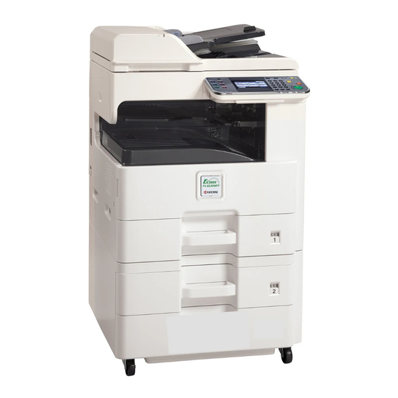
- ECOSYS FS-6525MFP
- Service manual
-
Contents
-
Table of Contents
-
Troubleshooting
-
Bookmarks
Quick Links
FS-6525MFP
FS-6530MFP
SERVICE
MANUAL
Published in December 2012
842MW113
2MWSM063
Rev.3
Related Manuals for Kyocera FS-6525MFP
Summary of Contents for Kyocera FS-6525MFP
-
Page 1: Service Manual
FS-6525MFP FS-6530MFP SERVICE MANUAL Published in December 2012 842MW113 2MWSM063 Rev.3…
-
Page 2
CAUTION RISK OF EXPLOSION IF BATTERY IS REPLACED BY AN INCORRECT TYPE. DISPOSE OF USED BATTERIES ACCORDING TO THE INSTRUCTIONS. It may be illegal to dispose of this battery into the municipal waste stream. Check with your local solid waste officials for details in your area for proper disposal. ATTENTION IL Y A UN RISQUE D’EXPLOSION SI LA BATTERIE EST REMPLACEE PAR UN MODELE DE TYPE INCORRECT. -
Page 3: Revision History
Revision history Revision Date Replaced pages Remarks 20 June 2012 1-3-12, 1-4-20, Address 20 August 2012 1-3-65, 1-3-121, 1-3-122, 2-4-12 1 December 2012 CONTENTS, 1-6-2, 2-4-9…
-
Page 4
This page is intentionally left blank. -
Page 5: Safety Precautions
Safety precautions This booklet provides safety warnings and precautions for our service personnel to ensure the safety of their customers, their machines as well as themselves during maintenance activities. Service personnel are advised to read this booklet carefully to familiarize themselves with the warnings and precautions described here before engaging in maintenance activities.
-
Page 6
Safety warnings and precautions Various symbols are used to protect our service personnel and customers from physical danger and to prevent damage to their property. These symbols are described below: DANGER: High risk of serious bodily injury or death may result from insufficient attention to or incorrect compliance with warning messages using this symbol. -
Page 7: Installation Precautions
1. Installation Precautions WARNING • Do not use a power supply with a voltage other than that specified. Avoid multiple connections to one outlet: they may cause fire or electric shock. When using an extension cable, always check that it is adequate for the rated current…………………. •…
-
Page 8
2. Precautions for Maintenance WARNING • Always remove the power plug from the wall outlet before starting machine disassembly….• Always follow the procedures for maintenance described in the service manual and other related brochures……………………….• Under no circumstances attempt to bypass or disable safety features including safety mechanisms and protective circuits. -
Page 9
• Do not remove the ozone filter, if any, from the copier except for routine replacement……. • Do not pull on the AC power cord or connector wires on high-voltage components when removing them; always hold the plug itself………………….•… -
Page 10
This page is intentionally left blank. -
Page 11: Specifications
2MW/2MX CONTENTS 1-1 Specifications 1-1-1 Specifications ……………………1-1-1 1-1-2 Parts names …………………….. 1-1-5 (1) Machine (front side)………………….1-1-5 (2) Machine (rear side)………………….1-1-7 (3) Operation panel …………………… 1-1-8 1-1-3 Machine cross section ………………….1-1-9 1-2 Installation 1-2-1 Installation environment………………….1-2-1 1-2-2 Unpacking and installation…………………
-
Page 12: Table Of Contents
(1) Precautions……………………1-5-1 (2) Drum unit …………………….. 1-5-1 (3) Toner ……………………..1-5-1 (4) How to tell a genuine Kyocera Mita toner container …………1-5-2 1-5-2 Outer covers …………………….. 1-5-3 (1) Detaching and refitting the front cover…………….1-5-3 (2) Detaching and refitting the rear cover …………….1-5-5 (3) Detaching and refitting the inner tray…………….
-
Page 13: Table Of Contents
2MW/2MX-3 1-5-12 Others ……………………..1-5-38 (1) Detaching and refitting the language sheet …………..1-5-38 (2) Detaching and refitting the conveying unit…………..1-5-39 (3) Detaching and refitting the eject fan motor…………..1-5-41 (4) Direction of installing the principal fan motors …………..1-5-41 1-6 Requirements on PWB Replacement 1-6-1 Upgrading the firmware ………………….
-
Page 14
2MW/2MX 2-4 Appendixes 2-4-1 Appendixes ……………………..2-4-1 (1) Maintenance kits………………….. 2-4-1 (2) Repetitive defects gauge ………………..2-4-2 (3) Firmware environment commands ………………. 2-4-3 (4) Chart of image adjustment procedures …………….2-4-11 (5) Wiring diagram ………………….. 2-4-13 Installation Guide PF-470/471(Paper feeder) DF-470/AK-470(Document finisher) FAX System(U) -
Page 15
2MW/2MX 1-1 Specifications 1-1-1 Specifications Machine Specifications Item 25ppm 30ppm Type Desktop Printing method Electrophotography by semiconductor laser, single drum system Originals Sheet, Book, 3-dimensional objects (maximum original size: A3/Ledger) Original feed system Fixed Cassette 60 to 163 g/m (Duplex: 60 to 163 g/m Paper weight MP tray 45 to 256 g/m… -
Page 16
2MW/2MX Specifications Item 25ppm 30ppm Cassette 500 sheets (80g/m Paper capacity MP tray 100 sheets (80 g/m , plain paper, A4/Letter or less) Output tray capacity 250 sheets (80g/m Continuous copying 1 to 999 sheets Light source White LED Scanning system Flat bed scanning by CCD image sensor Photoconductor a-Si drum (diameter 30 mm) -
Page 17: Document Processor
2MW/2MX Document processor Item Specifications Original feed method Automatic feed Supported original types Sheet originals Maximum: A3/Ledger Original sizes Minimum : A5/Statement Simplex: 45 to 160 g/m Original weights Duplex : 50 to 120 g/m Loading capacity 50 sheets (50 to 80 g/m ) or less Printer Specifications…
-
Page 18
2MW/2MX Scanner Item Specifications Windows XP (32bit/64bit), Windows Vista (32bit/64bit), Operating system Windows 7 (32bit/64bit), Windows Server 2003 (32bit/64bit), Windows Server 2008 (32bit/64bit), Windows Server 2008 R2 Resolution 600 dpi, 400 dpi, 300 dpi, 200 dpi, 200 × 100dpi, 200 × 400dpi File format JPEG, TIFF, PDF, XPS B/W : 40 images/min… -
Page 19: Parts Names
2MW/2MX 1-1-2 Parts names (1) Machine (front side) Figure 1-1-1 1. Cassette 9. DP top cover 2. Paper width guides 10. DP paper feed roller 3. Paper length guide 11. DP forwarding roller 4. MP (multi purpose) tray 12. DP separation pully 5.
-
Page 20
2MW/2MX Figure 1-1-2 16. Front cover 23. Feed shift guide 17. Toner container 24. Drum unit 18. Waste toner box 25. Developing unit 19. Right cover 1 26. Toner container lever 20. MP paper feed roller 27. Fuser unit 21. Registration roller 22. -
Page 21
2MW/2MX (2) Machine (rear side) Figure 1-1-3 28. Scanner lock lever 35. Outlet connector 29. Main power switch 36. Inlet connector 30. Filter cover 37. Option interface slot 1 31. DP interface connector 38. Option interface slot 2 32. Controller box cover 39. -
Page 22
2MW/2MX (3) Operation panel Figure 1-1-4 1. Message display 10. Quick No.search key 17. Favorite/Application key / 2. Interrupt key / LED 11. Enter key 3. Numeric keys 12. Start key / LED 18. Send key / LED 4. Logout key / LED 13. -
Page 23
2MW/2MX 1-1-3 Machine cross section Light path Paper path Paper path (option) Figure 1-1-5 1. Cassette 7. Drum unit 13. Image scanner unit (ISU) 2. Cassette paper feed section 8. Developer unit 14. Laser scanner unit (LSU) 3. MP tray paper feed section 9. -
Page 24
2MW/2MX This page is intentionally left blank. 1-1-10… -
Page 25: Installation Environment
2MW/2MX 1-2 Installation 1-2-1 Installation environment 1. Temperature: 10 to 32.5°C/50 to 90.5°F 2. Humidity: 15 to 80% RH 3. Power supply: 120 V AC, 12.0 A 220 — 240 V AC, 6.5 A 4. Power supply frequency: 50 Hz ±2%/60 Hz ±2% 5.
-
Page 26: Unpacking And Installation
2MW/2MX 1-2-2 Unpacking and installation (1) Installation procedure Start Unpack Remove the tapes and spacer Install the other optional devices Connect the power cord Install the job separator tray Installing toner Release the scanner lock lever Output an own-status report Install the optional paper feeder (option) (maintenance item U000) Load paper…
-
Page 27
2MW/2MX Unpacking Figure 1-2-2 1. Bottom case 9. Plastic bag (630 × 730) 17. CD-ROM * 2. Bottom pad R 10. Spacer B 18. Installation guide, etc. 3. Bottom pad L 11. Outer case 19. Plastic bag 4. Machine cover (740 × 700) 12. -
Page 28
2MW/2MX Remove the tapes and spacer Tape 1. Remove four tapes. Tape Tape Tape Figure 1-2-3 2. Open the DP top cover. DP top cover 3. Slide two DP original width guides and then remove the pad. 4. Close the DP top cover. DP original width guide Figure 1-2-4 1-2-4… -
Page 29
2MW/2MX 5. Open the DP. 6. Remove the protective sheet and paper. Protective sheet Paper Figure 1-2-5 7. Remove the tape. Tape Figure 1-2-6 1-2-5… -
Page 30
2MW/2MX 8. Peel off two protective sheets. 9. Remove the spacer. Spacer Protective sheets Figure 1-2-7 1-2-6… -
Page 31
2MW/2MX Install the job separator tray 1. Gently push the job separator tray into Left guide the machine along the guides. Right guide Job separator tray Figure 1-2-8 Release the scanner lock lever 1. Pull the scanner lock lever in the direc- tion of the arrow. -
Page 32
2MW/2MX Install the optional paper feeder (option) 1. Install the optional paper feeder as required. Paper feeder Figure 1-2-10 Load paper 1. Pressing the paper width adjusting tab as shown, move the paper width guides to fit the paper size. Paper width adjusting tab Cassette… -
Page 33
2MW/2MX 2. Adjust the paper length guide to fit the paper size. Paper length guides Figure 1-2-12 3. Align the paper so that it is abut with the Paper right end of the cassette. 4. Insert the cassette size plate. 5. -
Page 34
2MW/2MX Install the toner container 1. Open the front cover. 2. Hold the toner container vertically and Toner container tap the upper part five times or more. Turn the toner container upside down and tap the upper part five times or more. -
Page 35
2MW/2MX 4. Shake the toner container approxi- mately five or six times in the horizontal direction to stir toner. Figure 1-2-16 5. Gently push the toner container into the machine. Push the container all the way into the machine until it locks in place. Toner container Figure 1-2-17 1-2-11… -
Page 36
2MW/2MX Switch the cassette heater switch 1. Release the hook and then remove the switch cover. 2. Turn the cassette heater switch on. Cassette heater switch Note: When the cassette heater is used, it turns it on. 3. Refit the switch cover. Hook Switch cover Figure 1-2-18… -
Page 37
2MW/2MX Output an own-status report (maintenance item U000) 1. Enter 000 using the numeric keys and press the start key. 2. Select Maintenance and press the start key to output a list of the current settings of the maintenance items. 3. -
Page 38
2MW/2MX 1-2-3 Install the expansion memory (option) Procedure 1. Turn off the main power switch. Caution: Do not insert or remove expansion memory while machine power is on. Doing so may cause damage to the machine and the expansion memory. 2. -
Page 39
2MW/2MX 1-2-4 Option composition DF-470 (500 sheets) (Document finisher) AK-470 (Bridge unit) PF-790 (500 sheets x 1) (Paper feeder + Cabinet) PF-471 (500 sheets x 2) (Paper feeder) IB-50 USB key board (Gigabit ethernet board) FAX System(U) RAM Memory UG-33 ThinPrint Activation Kit Card Authentication Kit (B) 1-2-15… -
Page 40
2MW/2MX This page is intentionally left blank. 1-2-16… -
Page 41
2MW/2MX 1-3 Maintenance Mode 1-3-1 Maintenance mode The machine is equipped with a maintenance function which can be used to maintain and service the machine. (1) Executing a maintenance item Start Press the status/Job cancel key. Enter “10871087” using Maintenance mode is entered. the numeric keys. -
Page 42
2MW/2MX (2) Maintenance modes item list Item Initial Section Content of maintenance item setting General U000 Outputting an own-status report U001 Exiting the maintenance mode U002 Setting the factory default data U004 Setting the machine number U019 Displaying the ROM version Initialization U021 Memory initializing… -
Page 43
2MW/2MX Item Initial Section Content of maintenance item setting -/-/0/0 High voltage U100 Setting the main high voltage -/-/1800 0/0/0/0/190/650/900 U101 Setting the voltage for the primary transfer 1100/450/650/750 U108 Setting separation shift bias U111 Checking the drum drive time U118 Displaying the drum history U127… -
Page 44
2MW/2MX Item Initial Section Content of maintenance item setting Image U402 Adjusting margins of image printing 3.0/2.5/2.5/5.0 processing U403 Adjusting margins for scanning an original on the contact 2.0/2.0/2.0/2.0 glass U404 Adjusting margins for scanning an original from the DP 3.0/2.5/3.0/4.0 U407 Adjusting the leading edge registration for memory image… -
Page 45
2MW/2MX Item Initial Section Content of maintenance item setting U625 Setting the transmission system 1 Setting the auto redialing interval 3 (120 V) 2 (220-240 V) Setting the number of times of auto redialing 2 (120 V) 3 (220-240 V) U630 Setting communication control 1 Setting the communication starting speed… -
Page 46
2MW/2MX Item Initial Section Content of maintenance item setting U651 Setting modem 2 Modem output level -11 (120 V) -11 (220-240 V) DTMF output level (main value) 6 (120 V) 8 (220-240 V) DTMF output level (level difference) 2 (120 V) 2 (220-240 V) U660 Setting the NCU… -
Page 47
2MW/2MX (3) Contents of the maintenance mode items Item No. Description U000 Outputting an own-status report Description Outputs lists of the current settings of the maintenance items and paper jam and service call occurrences. Outputs the event log. Also sends output data to the USB memory. Purpose To check the current setting of the maintenance items, or paper jam or service call occurrences. -
Page 48: Event Log
2MW/2MX Item No. Description U000 Event log Event Log 04/Sep/2010 08:40 Firmware version 2K3_2000.000.000 2010.09.04 [XXXXXXXX] [XXXXXXXX] [XXXXXXXX] Paper Jam Log Service Call Log Count. Event Descriprions Count. Service Code 1876543 0501.01.08.01.01 1881214 01.6000 166554 4002.01.08.01.01 178944 01.2100 4988 0501.01.08.01.01 5296 01.4000 4988…
-
Page 49
2MW/2MX Item No. Description U000 Detail of event log Items Description System version System date Engine soft version Engine boot version Operation panel mask version Machine serial number Paper Jam Count. Event Remembers 1 to 16 of The total page count Log code (hexadeci- occurrence. -
Page 50
2MW/2MX Item No. Description U000 Items Description Paper Jam 4012: Registration sensor stay jam (cassette 2) cont. 4013: Registration sensor stay jam (cassette 3) 4201: Eject sensor non arrival jam (cassette 1) 4202: Eject sensor non arrival jam (cassette 2) 4203: Eject sensor non arrival jam (cassette 3) 4208: Eject sensor non arrival jam (duplex) 4209: Eject sensor non arrival jam (Mp tray) -
Page 51
2MW/2MX Item No. Description U000 Items Description Paper Jam 6813: Front adjustment plate operation OFF error cont. 6903: Rear adjustment plate operation ON error 6913: Rear adjustment plate operation OFF error 7013: Staple operation error 7023: Staple initialoperation error 7913: Sequence error 1 (operation prohibited) 7923: Sequence error 2 (initialoperation error) 7933: Sequence error 3 (Error in the reception of backup data) 7943: Sequence error 4 (standby) -
Page 52
2MW/2MX-1 Item No. Description U000 Items Description Paper Jam (d) Detail of paper type (Hexadecimal) cont. 01: Plain 0A: Color 15: Custom 1 02: Transparency 0B: Prepunched 16: Custom 2 03: Preprinted 0C: Envelope 17: Custom 3 04: Labels 0D: Cardstock 18: Custom 4 05: Bond 0E: Coated… -
Page 53
2MW/2MX Item No. Description U000 Items Description (10) Unknown Toner Count. Item Remembers 1 to 5 The total page count Unknown toner log of occurrence of at the time of the code unknown toner toner empty error (1 byte, 2 categories) detection. -
Page 54
2MW/2MX Item No. Description Exiting the maintenance mode U001 Description Exits the maintenance mode and returns to the normal copy mode. Purpose To exit the maintenance mode. Method Press the start key. The normal copy mode is entered. U002 Setting the factory default data Description Restores the machine conditions to the factory default settings. -
Page 55
2MW/2MX Item No. Description U004 Setting the machine number Description Sets or displays the machine number. Purpose To check or set the machine number. Method 1. Press the start key. If the machine serial number of engine PWB matches with that of main PWB Display Description Machine No. -
Page 56
2MW/2MX Item No. Description U019 Displaying the ROM version Description Displays the part number of the ROM fitted to each PWB. Purpose To check the part number or to decide, if the newest version of ROM is installed. Method 1. Press the start key. The ROM version are displayed. 2. -
Page 57
2MW/2MX Item No. Description U021 Memory initializing Description Initializes all settings, except those pertinent to the type of machine, namely each counter, ser- vice call history and mode setting. Also initializes backup RAM according to region specification selected in maintenance item U252 Setting the destination. Purpose To return the machine settings to their factory default. -
Page 58
2MW/2MX Item No. Description U030 Checking the operation of the motors Description Drives each motor. Purpose To check the operation of each motor. Method 1. Press the start key. 2. Select the motor to be operated. 3. Press the start key. The operation starts. Display Description Main… -
Page 59
2MW/2MX Item No. Description U032 Checking the operation of the clutches Description Turns each clutch on. Purpose To check the operation of each clutch. Method 1. Press the start key. 2. Select the clutch to be operated. 3. Press the start key. The operation starts. Display Description Motor… -
Page 60
2MW/2MX Item No. Description U034 Adjusting the print start timing Description Adjusts the leading edge registration or center line. Purpose Make the adjustment if there is a regular error between the leading edges of the copy image and original. Make the adjustment if there is a regular error between the center lines of the copy image and original. -
Page 61
2MW/2MX Item No. Description U034 5. Change the setting value using the cursor left/right keys or numeric keys. For output example 1, increase the value. For output example 2, decrease the value. Leading edge registration (20 ± 1.5 mm) Correct image Output Output example 1… -
Page 62
2MW/2MX Item No. Description U034 5. Change the setting value using the cursor left/right keys or numeric keys. For output example 1, increase the value. For output example 2, decrease the value. Center line of printing (within ± 0.5 mm) Correct image Output Output… -
Page 63
2MW/2MX Item No. Description U035 Setting the printing area for folio paper Description Changes the printing area for copying on folio paper. Purpose To prevent cropped images on the trailing edge or left/right side of copy paper by setting the actual printing area for folio paper. -
Page 64
2MW/2MX Item No. Description U051 Adjusting the deflection in the paper Description Adjusts the deflection in the paper at the registration roller. Purpose Make the adjustment if the leading edge of the copy image is missing or varies randomly, or if the copy paper is Z-folded. -
Page 65
2MW/2MX Item No. Description U053 Setting the adjustment of the motor speed Description Performs fine adjustment of the speeds of the motors. Purpose To adjust the speed of the respective motors when the magnification is not correct. Method 1. Press the start key. 2. -
Page 66
2MW/2MX Item No. Description U063 Adjusting the shading position Description Changes the shading position of the scanner. Purpose Used when the white line continue to appear longitudinally on the image after the shading plate is cleaned. This is due to flaws or stains inside the shading plate. To prevent this problem, the shading posi- tion should be changed so that shading is possible without being affected by the flaws or stains. -
Page 67
2MW/2MX Item No. Description U065 Adjusting the scanner magnification Description Adjusts the magnification of the original scanning. Purpose Make the adjustment if the magnification in the main scanning direction is incorrect. Make the adjustment if the magnification in the auxiliary scanning direction is incorrect. Caution Adjust the magnification of the scanner in the following order. -
Page 68
2MW/2MX Item No. Description U065 Adjustment: [X Scan Zoom] 1. Change the setting value using the cursor left/right keys or numeric keys. For copy example 1, increase the value. For copy example 2, decrease the value. Copy Original Copy example 2 example 1 Figure 1-3-6 2. -
Page 69
2MW/2MX Item No. Description U066 Adjusting the scanner leading edge registration Description Adjusts the scanner leading edge registration of the original scanning. Purpose Make the adjustment if there is a regular error between the leading edges of the copy image and original. -
Page 70
2MW/2MX Item No. Description U067 Adjusting the scanner center line Description Adjusts the scanner center line of the original scanning. Purpose Make the adjustment if there is a regular error between the center lines of the copy image and original. Adjustment 1. -
Page 71
2MW/2MX Item No. Description U068 Adjusting the scanning position for originals from the DP Description Adjusts the position for scanning originals from the DP. Performs the test copy at the four scan- ning positions after adjusting. Purpose Used when the image fogging occurs because the scanning position is not proper when the DP is used. -
Page 72
2MW/2MX Item No. Description U070 Adjusting the DP magnification Description Adjusts the DP original scanning speed. Purpose Make the adjustment if the magnification is incorrect in the auxiliary scanning direction when the DP is used. Adjustment 1. Press the start key. 2. -
Page 73
2MW/2MX Item No. Description U070 Caution Check the copy image after the adjustment. If the image is still incorrect, perform the following adjustments in maintenance mode. U071 U404 U070 ( P.1-3-34) ( P.1-3-62) Completion Press the stop key. The screen for selecting a maintenance item No. is displayed. 1-3-33… -
Page 74
2MW/2MX Item No. Description U071 Adjusting the DP scanning timing Description Adjusts the DP original scanning timing. Purpose Make the adjustment if there is a regular error between the leading or trailing edges of the origi- nal and the copy image when the DP is used. Method 1. -
Page 75
2MW/2MX Item No. Description U071 Adjustment: Trailing edge registration 1. Change the setting value using the cursor left/right keys or numeric keys. For copy example 1, increase the value. For copy example 2, decrease the value. Original Copy Copy example 1 example 2 Figure 1-3-12 2. -
Page 76
2MW/2MX Item No. Description U072 Adjusting the DP center line Description Adjusts the scanning start position for the DP original. Purpose Make the adjustment if there is a regular error between the centers of the original and the copy image when the DP is used. Adjustment 1. -
Page 77
2MW/2MX Item No. Description U089 Outputting a MIP-PG pattern Description Selects and outputs the MIP-PG pattern created in the machine. Purpose To check copier status other than scanner when adjusting image printing, using MIP-PG pattern output (with-out scanning). Method 1. Press the start key. 2. -
Page 78
2MW/2MX Item No. Description U099 Adjusting original size detection Description Checks the operation of the original size sensor and sets the sensing threshold value. Purpose To adjust the sensitiveness of the sensor and size judgement time if the original size sensor mal- functions frequently due to incident light or the like. -
Page 79
2MW/2MX Item No. Description U100 Setting the main high voltage Description Performs main charging. Purpose To check main charging. Method 1. Press the start key. 2. Select the item. The screen for executing each item is displayed. Display Description Main charger Confirming of main motor driving and main charger operating Laser Confirming of laser operating… -
Page 80
2MW/2MX Item No. Description U100 Setting: [Idc Bias] 1. Select an item to be set. 2. Change the setting value using the cursor left/right keys or numeric keys. Setting Initial Display Description range setting Full Idc bias regulations value at the full 0?255 speed (Only the display) Half… -
Page 81
2MW/2MX Item No. Description U101 Setting the voltage for the primary transfer Description Sets the control voltage for the primary transfer. Purpose To change the setting when any density problems, such as too dark or light, occur. Setting 1. Press the start key. 2. -
Page 82
2MW/2MX Item No. Description U108 Setting separation shift bias Description Adjusts output of separation shift bias and ON/OFF timing. Purpose To set when the separated malfunction of the paper occurs. Setting 1. Press the start key. 2. Select [Mode]. 3. Change the setting value using the cursor left/right keys or numeric keys. Setting Initial Display… -
Page 83
2MW/2MX Item No. Description U111 Checking the drum drive time Description Displays the drum drive time for checking a figure, which is used as a reference when correcting the high voltage based on time. Purpose To check the drum status. Method 1. -
Page 84
2MW/2MX Item No. Description U127 Checking/clearing the transfer count Description Displays and clears the counts of the transfer counter. Purpose To check the count after replacement of the transfer roller. Also to clear the counts after replacing transfer roller. Method 1. -
Page 85
2MW/2MX Item No. Description U140 Displaying developer bias Description Displays various developer bias value. Purpose To check the developer bias value. Setting 1. Press the start key. 2. Select the item to be set. 3. Change the setting value using the cursor left/right keys or numeric keys. Setting Initial Display… -
Page 86
2MW/2MX Item No. Description U147 Setting for toner applying operation Description Sets the mode for removing charged toner in the developer unit (T7 control: Toner applying oper- ation). Purpose Changing settings are not required. However, when the documents with lower print density (e.g. less than 2%) should customarily printed in a great volume, mode must be changed. -
Page 87
2MW/2MX Item No. Description U157 Checking the developer drive time Description Displays the developer drive time for checking a figure, which is used as a reference when cor- recting the toner control. Purpose To check the developer drive time after replacing the developer unit. Method 1. -
Page 88
2MW/2MX Item No. Description U199 Displaying fuser heater temperature Description Displays the detected fuser temperature. Purpose To check the fuser temperature. Method 1. Press the start key. The fuser temperature is displayed. Completion Press the stop key. The screen for selecting a maintenance mode No. is displayed. U201 Initializing the touch panel Description… -
Page 89
2MW/2MX Item No. Description U203 Checking DP operation Description Simulates the original conveying operation separately in the DP. Purpose To check the DP operation. Method 1. Press the start key. 2. Place an original in the DP if running this simulation with paper. 3. -
Page 90
2MW/2MX Item No. Description U207 Checking the operation panel keys Description Checks operation of the operation panel keys. Purpose To check operation of all the keys and LEDs on the operation panel. Method 1. Press the start key. The screen for executing is displayed. 2. -
Page 91
2MW/2MX Item No. Description U243 Checking the operation of the DP motors Description Turns the motors or clutches in the DP on. Purpose To check the operation of the DP motors and clutches. Method 1. Press the start key. 2. Select the item to be operated. 3. -
Page 92
2MW/2MX Item No. Description U244 Checking the DP switches Description Displays the status of the respective switches in the DP. Purpose To check if respective switches in the DP operate correctly. Method 1. Press the start key. 2. Turn each switch or sensor on and off manually to check the status. When a switch or sensor is detected to be in the ON position, the display for that switch or sensor will be “1”. -
Page 93
2MW/2MX Item No. Description U250 Checking/clearing the maintenance cycle Description Changes preset values for maintenance cycle and automatic grayscale adjustment. Purpose Provides changing the time when the message to acknowledge to conduct maintenance and automatic grayscale adjustment is periodically displayed. Setting 1. -
Page 94
2MW/2MX Item No. Description U252 Setting the destination Description Switches the operations and screens of the machine according to the destination. Purpose To be executed after initializing the backup RAM, in order to return the setting to the value before replacement or initialization. -
Page 95
2MW/2MX Item No. Description U253 Switching between double and single counts Description Switches the count system for the total counter and other counters. Purpose Used to select, according to the preference of the user (copy service provider), if folio size paper is to be counted as one sheet (single count) or two sheets (double count). -
Page 96
2MW/2MX Item No. Description U265 Setting OEM purchaser code Description Sets the OEM purchaser code. Purpose Sets the code when replacing the main PWB and the like. Setting 1. Press the start key. 2. Change the preset value using the numeric keys. 3. -
Page 97
2MW/2MX Item No. Description U326 Setting the black line cleaning indication Description Sets whether to display the cleaning guidance when detecting the black line. Purpose Displays the cleaning guidance in order to make the call for service with the black line decrease by the rubbish on the contact glass when scanning from the DP. -
Page 98
2MW/2MX Item No. Description U332 Setting the size conversion factor Description Sets the coefficient of nonstandard sizes in relation to the A4/Letter size. The coefficient set here is used to convert the black ratio in relation to the A4/Letter size and to display the result in user simulation. -
Page 99
2MW/2MX Item No. Description U343 Switching between duplex/simplex copy mode Description Switches the initial setting between duplex and simplex copy. Purpose To be set according to frequency of use: set to the more frequently used mode. Setting 1. Press the start key. 2. -
Page 100
2MW/2MX Item No. Description U402 Adjusting margins of image printing Description Adjusts margins for image printing. Purpose Make the adjustment if margins are incorrect. Adjustment 1. Press the start key. 2. Press the system menu key. 3. Press the start key to output a test pattern. 4. -
Page 101
2MW/2MX Item No. Description U403 Adjusting margins for scanning an original on the contact glass Description Adjusts margins for scanning the original on the contact glass. Purpose Make the adjustment if margins are incorrect. Adjustment 1. Press the start key. 2. -
Page 102
2MW/2MX Item No. Description U404 Adjusting margins for scanning an original from the DP Description Adjusts margins for scanning the original from the DP. Purpose Make the adjustment if margins are incorrect. Caution Before making this adjustment, ensure that the following adjustments have been made in mainte- nance mode U402 U403… -
Page 103
2MW/2MX Item No. Description U407 Adjusting the leading edge registration for memory image printing Description Adjusts the leading edge registration during memory copying. Purpose Make the following adjustment if there is a regular error between the leading edge of the copy image on the front face and that on the reverse face during duplex switchback copying. -
Page 104
2MW/2MX Item No. Description U411 Adjusting the scanner automatically Description Uses a specified original and automatically adjusts the following items in the scanner and the DP scanning sections. Scanner section: Original size magnification, leading edge timing, center line, input gamma, input gamma in monochrome mode and matrix DP scanning section: Original size magnification, leading edge timing, center line Purpose… -
Page 105
2MW/2MX-2 Item No. Description U411 Method: DP 1. Select [DP]. 2. Set a specified original (P/N: 302AC68243) in the DP. * : When running this test chart, you first must clean the feed rollers with alcohol and ensure the DP width guides are correctly positioned against the original. 3. -
Page 106
2MW/2MX Item No. Description U411 Codes Description Original error (Dirt of the original for adjustment and damage) Original error (scanner input gamma adjustment) Original error (scanner matrix adjustment) TestRAW acquisition completion Completion Press the stop key. The screen for selecting a maintenance item is displayed. 1-3-66… -
Page 107
2MW/2MX Item No. Description U425 Setting the target Description Enters the lab values that is indicated on the back of the chart (P/N: 7505000005) used for adjustment. Purpose Performs data input in order to correct for differences in originals during automatic adjustment. Method 1. -
Page 108
2MW/2MX Item No. Description U425 Setting: [Adjust Original] 1. Measure the distance from the leading edge to the top of black belt 1 of the original at A, B and C. Measurement procedure 1) Measure the distance from the leading edge to the top of black belt 1 of the original at A (30 mm from the left edge), B (148.5 mm from the left edge) and C (267 mm from the left edge), respectively. -
Page 109
2MW/2MX Item No. Description U432 Setting the center offset for the exposure Description Sets the offset value for the setting data for exposure centering adjustment under user simula- tion. For example, if the value for the exposure centering adjustment is set to -1 and you change the offset value to +2, image processing is performed as though the exposure centering adjust- ment setting is +1. -
Page 110
2MW/2MX Item No. Description U470 Setting the JPEG compression ratio Description Sets the compression ratio for JPEG images in each image quality mode. Purpose To change the setting in accordance with the image that the user is copying. For example, in order to soften the coarseness of the image when making copies at over 200% magnification, change the level of compression by raising the value. -
Page 111
2MW/2MX Item No. Description U470 2. Select the item to be set. 3. Change the setting value using the cursor left/right keys or numeric keys. [Photo] or [Text] Setting Initial Display Description range setting Y1 to Y5 Compression ratio of brightness 1 to 100 30/40/51/70/90 CbCr1 to CbCr5 Compression ratio of color differential 1 to 100… -
Page 112
2MW/2MX Item No. Description U600 Initializing all data Description Initializes software switches and all data in the backup data on the FAX control PWB, according to the destination and OEM. Executes the check of the file system, when abnormality of the file system is detected, initializes the file system, communication past record and register setting contents. -
Page 113
2MW/2MX Item No. Description U601 Initializing permanent data Description Initializes software switches on the FAX control PWB according to the destination and OEM. Purpose To initialize the FAX control PWB without changing user registration data. Method 1. Press the start key. 2. -
Page 114
2MW/2MX Item No. Description U604 Setting user data 2 Description Makes user settings to enable the use of the machine as a fax. Purpose Use this if the user wishes to adjust the number of rings that occur before the unit switches into fax receiving mode when fax/telephone auto-select is enabled. -
Page 115
2MW/2MX Item No. Description U610 Setting system 1 Description Makes settings for fax reception regarding the sizes of the fax paper and received images and automatic printing of the protocol list. Method 1. Press the start key. 2. Select the item to be set. Display Description Cut Line:A4… -
Page 116
2MW/2MX Item No. Description U610 Setting the number of lines to be ignored when receiving a fax in the auto reduction mode Sets the maximum number of lines to be ignored if the received data volume exceeds the record- ing capacity when the data is recorded in the auto reduction mode. If the number of excess lines is below the setting, those lines are ignored. -
Page 117
2MW/2MX Item No. Description U611 Setting system 2 Description Sets the number of adjustment lines for automatic reduction. Method 1. Press the start key. 2. Select the item to be set. Display Description Adj Lines Sets the number of adjustment lines for automatic reduction. Adj Lines(A4) Sets the number of adjustment lines for automatic reduction when A4 paper is set. -
Page 118
2MW/2MX Item No. Description U612 Setting system 3 Description Makes settings for fax transmission regarding operation and automatic printing of the protocol list. Method 1. Press the start key. 2. Select the item to be set using the cursor up/down keys. Display Description Auto Reduct… -
Page 119
2MW/2MX Item No. Description U615 Setting system 6 Description Makes settings for fax reception regarding the sizes of the fax paper and received images. Purpose To set the maximum recording width and processing method when 11″ width fax paper is loaded on an inch specification machine. -
Page 120
2MW/2MX Item No. Description U625 Setting the transmission system 1 Description Makes settings for the auto redialing interval and the number of times of auto redialing. Purpose Change the setting to prevent the following problems: fax transmission is not possible due to too short redial interval, or fax transmission takes too much time to complete due to too long redial interval. -
Page 121
2MW/2MX Item No. Description U630 Setting communication control 1 Description Makes settings for fax transmission regarding the communication. Method 1. Press the start key. 2. Select the item to be set. Display Description TX Speed Sets the communication starting speed. RX Speed Sets the reception speed. -
Page 122
2MW/2MX Item No. Description U630 Setting the waiting period to prevent echo problems at the sender Sets the period before a DCS signal is sent after a DIS signal is received. Used when problems occur due to echoes at the sender. 1. -
Page 123
2MW/2MX Item No. Description U631 Setting communication control 2 Description Makes settings regarding fax transmission. Method 1. Press the start key. 2. Select the item to be set. Display Description ECM TX Sets ECM transmission. ECM RX Sets ECM reception. CED Freq Sets the frequency of the CED signal. -
Page 124
2MW/2MX Item No. Description U632 Setting communication control 3 Description Makes settings for fax transmission regarding the communication. Method 1. Press the start key. 2. Select the item to be set. Display Description DIS 4Byte Sets the DIS signal to 4 bytes. Num OF CNG(F/T) Sets the CNG detection times in the fax/telephone auto select mode. -
Page 125
2MW/2MX Item No. Description U633 Setting communication control 4 Description Makes settings for fax transmission regarding the communication. Purpose To reduce transmission errors when a low quality line is used. Method 1. Press the start key. 2. Select the item to be set. Display Description V.34… -
Page 126
2MW/2MX Item No. Description U633 Setting the number of times of DIS signal reception Sets the number of times to receive the DIS signal to once or twice. Used as one of the correction measures for transmission errors and other problems. 1. -
Page 127
2MW/2MX Item No. Description U640 Setting communication time 1 Description Sets the detection time when one-shot detection is selected for remote switching. (This setting item will be displayed, but the setting made is ineffective.) Sets the detection time when continuous detection is selected for remote switching. (This setting item will be displayed, but the setting made is ineffective.) Method 1. -
Page 128
2MW/2MX Item No. Description U641 Setting communication time 2 Description Sets the time-out time for fax transmission. Purpose To improve transmission performance for international communications mainly. Method 1. Press the start key. 2. Select the item to be set. Display Description T0 Time Out Sets the T0 time-out time. -
Page 129
2MW/2MX Item No. Description U641 Setting the T2 time-out time The T2 time-out time decides the following. From CFR signal output to image data reception From image data reception to the next signal reception In ECM, from RNR signal detection to the next signal reception 1. -
Page 130
2MW/2MX Item No. Description U641 Setting the Tb2 time-out time In the fax/telephone auto select mode, sets the time to start ringing an operator through the con- nected telephone after receiving a call as a fax machine (see figure 1-3-19). In the fax/telephone auto select mode, change the setting when fax reception is unsuccessful or a telephone fails to receive a call. -
Page 131
2MW/2MX Item No. Description U650 Setting modem 1 Description Sets the G3 cable equalizer. Sets the modem detection level. Purpose Perform the following adjustment to make the equalizer compatible with the line characteristics. To improve the transmission performance when a low quality line is used. Method 1. -
Page 132
2MW/2MX Item No. Description U651 Setting modem 2 Description Sets the modem output level. Sets the DTMF output level of a push-button dial telephone. Purpose Used if problems occur when sending a signal with a push-button dial telephone. Setting 1. Press the start key. 2. -
Page 133
2MW/2MX Item No. Description U660 Setting the NCU Description Makes setting regarding the network control unit (NCU). Purpose To be executed as required. Method 1. Press the start key. 2. Select the item to be set. Display Description Exchange Sets the connection to PBX/PSTN. Dial Tone Sets PSTN dial tone detection. -
Page 134
2MW/2MX Item No. Description U660 Setting busy tone detection When a fax signal is sent, sets whether the line is disconnected immediately after a busy tone is detected, or the busy tone is not detected and the line remains connected until T0 time-out time. Fax transmission may fail due to incorrect busy tone detection. -
Page 135
2MW/2MX Item No. Description U670 Outputting lists Description Outputs a list of data regarding fax transmissions. Printing a list is disabled either when a job is remaining in the buffer or when [Pause All Print Jobs] is pressed to halt printing. Purpose To check conditions of use, settings and transmission procedures of the fax. -
Page 136
2MW/2MX Item No. Description U695 FAX function customize Description Sets fax batch transmission ON/OFF. Also changes the print size priority at the time of small size reception. Purpose To be executed as required. Setting 1. Select the setting. Display Description FAX Bulk TX fax batch transmission On/Off A5 Pt Pri Chg… -
Page 137
2MW/2MX Item No. Description U699 Setting the software switches Description Sets the software switches on the FAX control PWB individually. Purpose To change the setting when a problem such as split output of received originals occurs. Since the communication performance is largely affected, normally this setting need not be changed. -
Page 138
2MW/2MX Item No. Description U699 <Communication time setting> Item 76543210 T3 timeout setting 76543210 T4 timeout setting (automatic equipment) 76543210 T5 timeout setting 76543210 Time before transmission of CNG (1100 Hz) signal 76543210 T0 timeout setting (manual equipment) 7 Phase C timeout in ECM reception 76543210 Timeout 1 in countermeasures against echo 76543210 Timeout for FSK detection start in V.8 <Modem setting>… -
Page 139
2MW/2MX Item No. Description U901 Checking copy counts by paper feed locations Description Displays or clears copy counts by paper feed locations. Purpose To check the time to replace consumable parts. Also to clear the counts after replacing the con- sumable parts. -
Page 140
2MW/2MX Item No. Description U903 Checking/clearing the paper jam counts Description Displays or clears the jam counts by jam locations. Purpose To check the paper jam status. Also to clear the jam counts after replacing consumable parts. Method 1. Press the start key. 2. -
Page 141
2MW/2MX Item No. Description U904 Checking/clearing the call for service counts Description Displays or clears the service call code counts by types. Purpose To check the service call code status by types. Also to clear the service call code counts after replacing consumable parts. Method 1. -
Page 142
2MW/2MX Item No. Description U905 Checking counts by optional devices Description Displays the counts of document processor or document finisher. Purpose To check the use of document processor or document finisher. Method 1. Press the start key. 2. Select the device to be checked. The count of the selected device is displayed. Display Description Counts of document processor… -
Page 143
2MW/2MX Item No. Description U917 Setting backup data reading/writing Description Retrieves the backup data to a USB memory from the machine; or writes the data from the USB memory to the machine. Purpose Machine information is backed up and restored. Method 1. -
Page 144
2MW/2MX Item No. Description U917 Error Codes Codes Description Codes Description e002 Parameter error e31e User managements error e003 File write error e31f User managements open error e004 File initialization error e320 User managements error e005 File error e321 User managements open error e006 Processing error e322… -
Page 145
2MW/2MX Item No. Description U917 Error Codes Codes Description Codes Description e913 Log file open error d008 File rename error e914 Log file error in writing d009 File open error e915 Directory open error d00a File close error e916 Directory error in reading d00b File reading error e917… -
Page 146
2MW/2MX Item No. Description U935 Relay board maintenance Description Sets the mode when call for service (C0060) occurs. Purpose Sets the machine status temporarily when call for service (C0060) occurs. However, after the set- ting, call for service (C0060) occurs again when progress of period. Setting 1. -
Page 147
2MW/2MX Item No. Description U942 Setting of deflection for feeding from DP Description Adjusts the deflection generated when the document processor is used. Purpose Use this mode if an original non-feed jam, oblique feed or wrinkling of original occurs when the document processor is used. -
Page 148
2MW/2MX Item No. Description U977 Data capture mode Description Store the print data sent to the machine into USB memory. Purpose In case to occur the error at printing, check the print data sent to the machine. Method 1. Press the power key on the operation panel, and after verifying the main power indicator has gone off, switch off the main power switch. -
Page 149
2MW/2MX Item No. Description U985 Displaying the developer history Description Displays the past record of machine number and the developer counter. Purpose To check the count value of machine number and the developer counter. Method 1. Press the start key. The each history displayed by five cases. Display Description Machine History 1 — 5… -
Page 150: Service Mode
2MW/2MX 1-3-2 Service mode The machine is equipped with a maintenance function which can be used to maintain and service the machine. (1) Printing the service status page Start Press the System Menu/Counter key. The Sys. Menu/Count. menu appears. Select [Report]. Select [Rerort print].
-
Page 151: Service Status Page
2MW/2MX Service items Description Service status page (1) Service Status Page 2011/09/28 15:15 Firmware version 2MW_2F00.001.001 2011.09.28 [XXXXXXXX] [XXXXXXXX] [XXXXXXXX] Controller Information Memory status (29) Standard Size 128.0 KB FRPO Status Option Slot 128.0 KB User Top Margin A1+A2/100 0.00 Total Size 256.0 KB User Left Margin…
-
Page 152: Engine Information
2MW/2MX Service items Description Service status page (2) Service Status Page 2011/09/28 15:15 Firmware version 2MW_2F00.001.001 2011.09.28 [XXXXXXXX] [XXXXXXXX] [XXXXXXXX] Engine Information Send Information (30) (34) NVRAM Version _1F31225_1F31225 Date and Time 09/03/05 15:30 (31) (35) Address mail@bjd.ne.jp FAX BOOT Version 2K3_5000.001.001 FAX APL Version 2K3_5100.001.001…
-
Page 153
2MW/2MX Service items Description Detail of service status page Description Supplement Firmware version System date Engine soft version Engine boot version Operation panel mask version Machine serial number Standard memory size Optional memory size Total memory size (10) Local time zone (11) Report output date Day/Month/Year hour:minute… -
Page 154
2MW/2MX Service items Description Description Supplement (29) FRPO setting (30) NV RAM version _ 1F3 1225 _ 1F3 1225 (a) (b) (d) (e) (a) Consistency of the present software version and the database _ (underscore): OK * (Asterisk): NG (b) Database version (c) The oldest time stamp of database version (d) Consistency of the present software version and the ME firmware version… -
Page 155
2MW/2MX Service items Description Description Supplement (43) Panel lock information 0: OFF/1: Partial lock/2: Full lock (44) USB information U00: Not installed/U01: Full speed/U02: Hi speed (45) Paper handling information 0: Paper source unit select/1: Paper source unit (46) Black and white printing double 0: All single counts count mode 3: Folio, Single count, Less than 330 mm (length) -
Page 156
2MW/2MX Service items Description Description Supplement (62) Altitude 0: Standard 1: High altitude 1 2: High altitude 2 (63) Charger roller correction 1 to 5 (64) Shift restrictions of an one-sheet 0:Off original 1:On (65) Drum serial number Black Code conversion 1-3-116… -
Page 157
2MW/2MX (2) Executing a service mode Start Press the System Menu/Counter key. The Sys. Menu/Count. menu appears. Select [Adjust/Maint.] The Adjust/Maint. menu appears. using the cursor up/down keys. Select [Service Setting] The Service Setting menu appears. using the cursor up/down keys. The selected service mode is run. -
Page 158
2MW/2MX Service items Description Maintenance Reset the counter of the maintenance kit. Description Reset the kit counter when replacing the maintenance kit. The menu is displayed only when replacing the maintenance kit. Purpose Perform when the maintenance kit is replaced. Method 1. -
Page 159
2MW/2MX Service items Description FAX country FAX Country Code code Description Initializes software switches and all data in the backup data on the FAX control PWB, according to the destination. Purpose To initialize the FAX control PWB. Method 1. Enter the Service Setting menu. 2. -
Page 160
2MW/2MX Service items Description FAX call Setting FAX call setting Description Selects if a fax is to be connected to either a PBX or public switched telephone network. Selects the mode to connect an outside call when connected to a PBX. Access code registration for connection to PSTN. -
Page 161
2MW/2MX-2 Service items Description Memory Perform a memory diagnostic Diagnostics Description Diagnose memory at power up (whether reading and writing are executable). Purpose Execute memory check in purpose of rectifying a defective memory device which may possibly cause an unresolvable F call, locking, or abnormal images. Method 1. -
Page 162
2MW/2MX-2 This page is intentionally left blank. 1-3-122… -
Page 163: Paper Misfeed Detection
2MW/2MX 1-4 Troubleshooting 1-4-1 Paper misfeed detection (1) Paper misfeed indication When a paper misfeed occurs, the machine immediately stops printing and displays the paper misfeed mes- sage on the operation panel. To remove paper misfed in the machine, pull out the cassette, open the right cover.
-
Page 164
2MW/2MX Code Contents Conditions location* 0000 Initial jam The power is turned on when a sensor in the con- veying system is on. 0100 Secondary paper feed Secondary paper feed request given by the con- request time out troller is unreachable. 0101 Waiting for process package Process package won’t be ready. -
Page 165
2MW/2MX Code Contents Conditions location* 1403 PF feed sensor 1 non arrival PF feed sensor 1 (PFFS1) does not turn on during paper feed from cassette 3. 1413 PF feed sensor 1 stay jam PF feed sensor 1 (PFFS1) does not turn off during paper feed from cassette 3. -
Page 166
2MW/2MX Code Contents Conditions location* 4311 Duplex sensor stay jam The duplex sensor (DUS) does not turn off during paper feed from cassette 1. 4312 The duplex sensor (DUS) does not turn off during paper feed from cassette 2. 4313 The duplex sensor (DUS) does not turn off during paper feed from cassette 3. -
Page 167
2MW/2MX Code Contents Conditions location* 5011 Bridge conveying sensor 3 The bridge conveying sensor 3 (BRCS3) does not stay jam turn off during paper feed from cassette 1. 5012 The bridge conveying sensor 3 (BRCS3) does not turn off during paper feed from cassette 2. 5013 The bridge conveying sensor 3 (BRCS3) does not turn off during paper feed from cassette 3. -
Page 168
2MW/2MX Code Contents Conditions location* 7933 Sequence error 3 A backup data command has been received in the (Error in the reception of state the operation has initiated. backup data) 7943 Sequence error 4 Start of operation has been received in the state of (standby) prohibiting to stand by. -
Page 169
2MW/2MX 1-4-2 Self-diagnostic function (1) Self-diagnostic function This machine is equipped with self-diagnostic function. When a problem is detected, the machine stops print- ing and display an error message on the operation panel. An error message consists of a message prompting a contact to service personnel and a four-digit error code indicating the type of the error. -
Page 170
2MW/2MX Check procedures/ Code Contents Causes corrective measures 0150 Backup memory read/write Improper installa- Check the installation of the EEPROM and error (engine PWB) tion engine PWB remedy if necessary. Detecting engine PWB EEPROM. EEPROM communication Defective engine Replace the engine PWB and check for cor- error. -
Page 171
2MW/2MX Check procedures/ Code Contents Causes corrective measures 0870 FAX control PWB to main Improper installa- Reinstall the FAX control PWB. PWB high capacity data tion FAX control transfer error PWB. High-capacity data transfer Defective FAX con- Replace the FAX control PWB or main PWB between the FAX control PWB trol PWB or main and check for correct operation (see page 1-… -
Page 172
2MW/2MX Check procedures/ Code Contents Causes corrective measures 1020 PF lift motor error Defective bottom Check to see if the bottom plate can move (paper feeder) plate elevation smoothly and repair it if any problem is After cassette 2 is inserted, mechanism in the found. -
Page 173
2MW/2MX Check procedures/ Code Contents Causes corrective measures 1900 Paper feeder EEPROM error Defective PF main Replace the PF main PWB (Refer to the ser- When writing the data, the PWB. vice manual for the paper feeder). write data and the read data is Device damage of Contact the Service Administrative Division. -
Page 174
2MW/2MX Check procedures/ Code Contents Causes corrective measures 3100 ISU home position error Defective connec- Reinsert the connector. Also check for conti- The home position is not cor- tor cable or poor nuity within the connector cable. If none, rect when the power is turned contact in the con- replace the cable. -
Page 175
2MW/2MX Check procedures/ Code Contents Causes corrective measures 4010 Polygon motor steady-state Defective connec- Reinsert the connector. Also check for conti- error tor cable or poor nuity within the connector cable. If none, Stable OFF is detected for 1 s contact in the con- replace the cable. -
Page 176
2MW/2MX Check procedures/ Code Contents Causes corrective measures 6020 Abnormally high fuser Deformed connec- See page 1-4-15. thermistor temperature tor pin. The fuser thermistor detects a Defective triac. See page 1-4-15. temperature higher than Shorted fuser Replace the fuser unit (see page 1-5-21). 230°C/446°F continuously for thermistor. -
Page 177
2MW/2MX Check procedures/ Code Contents Causes corrective measures 6000/ Broken fuser heater wire Deformed connec- If the I/F connector pins of the fuser unit and 6020/ Abnormally high fuser tor pin. the main unit are deformed owing to foreign 6030/ thermistor temperature matters, such as paper dusts, replace the 6050… -
Page 178
2MW/2MX Check procedures/ Code Contents Causes corrective measures 7810 Short-circuited external Defective connec- Reinsert the connector. Also check for conti- thermistor wire tor cable or poor nuity within the connector cable. If none, The thermistor output value is contact in the con- replace the cable. -
Page 179
2MW/2MX Check procedures/ Code Contents Causes corrective measures 8040 Belt problem (document fin- Defective connec- Reinsert the connector. Also check for conti- isher) tor cable or poor nuity within the connector cable. If none, The belt sensor does not turn contact in the con- replace the cable. -
Page 180
2MW/2MX Check procedures/ Code Contents Causes corrective measures 8320 Adjustment motor 2 prob- Defective connec- Reinsert the connector. Also check for conti- lem (document finisher) tor cable or poor nuity within the connector cable. If none, The adjustment sensor 2 does contact in the con- replace the cable. -
Page 181
2MW/2MX Check procedures/ Code Contents Causes corrective measures 8360 Slide motor problem (docu- Defective connec- Reinsert the connector. Also check for conti- ment finisher) tor cable or poor nuity within the connector cable. If none, The slide sensor does not turn contact in the con- replace the cable. -
Page 182
2MW/2MX-1 Check procedures/ Code Contents Causes corrective measures 8990 Document finisher commu- Defective connec- Reinsert the connector. Also check for conti- nication error tor cable or poor nuity within the connector cable. If none, contact in the con- replace the cable. nector. -
Page 183: Image Formation Problems
2MW/2MX 1-4-3 Image formation problems If the part causing the problem was not supplied, use the unit including the part for replacement. (1) No image (2) No image (3) Image is too (4) The back- (5) White streaks appears (entirely appears (entirely light.
-
Page 184
2MW/2MX (1) No image appears (entirely white). Print example Causes Check procedures/corrective measures Defective Defective connector cable Reinsert the connector. Also check for conti- transfer or poor contact in the con- nuity within the connector cable. If none, bias output. nector. -
Page 185
2MW/2MX (3) Image is too light. Print example Causes Check procedures/corrective measures Defective Defective connector cable Reinsert the connector. Also check for conti- transfer or poor contact in the con- nuity within the connector cable. If none, charger out- nector. replace the cable. -
Page 186
2MW/2MX (6) Black streaks are printed vertically. Print example Causes Check procedures/corrective measures Dirty contact glass. Clean the contact glass. Dirty slit glass. Clean the slit glass. Dirty or flawed drum. Perform the drum refresh operation. Flawed drum. Replace the drum unit (see page 1-5-19). Deformed or worn cleaning Replace the drum unit (see page 1-5-19). -
Page 187
2MW/2MX (9) Spots are printed. Print example Causes Check procedures/corrective measures Dirty contact glass. Clean the contact glass. Dirty or flawed drum. Perform the drum refresh operation. Flawed drum. Replace the drum unit (see page 1-5-19). Deformed or worn cleaning Replace the drum unit (see page 1-5-19). -
Page 188
2MW/2MX (13) Paper is wrinkled. Print example Causes Check procedures/corrective measures Paper curled. Check the paper storage conditions. Paper damp. Check the paper storage conditions. Defective pressure springs. Replace the fuser unit (see page 1-5-21). (14) Offset occurs. Print example Causes Check procedures/corrective measures Deformed or worn cleaning… -
Page 189
2MW/2MX (17) Image is out of focus. Print example Causes Check procedures/corrective measures Defective image scanning Replace the image scanning unit (see page 1-5-24). unit. Drum condensation. Perform the drum refresh operation. (18) Image center does not align with the original center. Print example Causes Check procedures/corrective measures… -
Page 190: Electric Problems
2MW/2MX 1-4-4 Electric problems If the part causing the problem was not supplied, use the unit including the part for replacement. Troubleshooting to each failure must be in the order of the numbered symptoms. Problem Causes Check procedures/corrective measures 1. No electricity at the Measure the input voltage.
-
Page 191
2MW/2MX Problem Causes Check procedures/corrective measures 1. Defective connector Reinsert the connector. Also check for continuity within the Controller fan cable or poor con- connector cable. If none, replace the cable. motor does not tact in the connector. Controller fan motor and main PWB (YC41) operate. -
Page 192
2MW/2MX Problem Causes Check procedures/corrective measures (11) 1. Defective connector Reinsert the connector. Also check for continuity within the Feedshift solenoid cable or poor con- connector cable. If none, replace the cable. does not operate. tact in the connector. Feedshift solenoid and engine PWB (YC5) 2. -
Page 193
2MW/2MX Problem Causes Check procedures/corrective measures (16) 1. Deformed actuator of Check visually and replace if necessary. A message indicat- the interlock switch. ing cover open is 2. Defective interlock Replace the interlock switch. displayed when the switch. front cover or right cover is closed. -
Page 194
2MW/2MX Problem Causes Check procedures/corrective measures (21) 1. Defective connector Reinsert the connector. Also check for continuity within the DP paper feed cable or poor con- connector cable. If none, replace the cable. clutch does not tact in the connector. DP paper feed clutch and DP main PWB (YC8) operate. -
Page 195: Mechanical Problems
2MW/2MX 1-4-5 Mechanical problems If the part causing the problem was not supplied, use the unit including the part for replacement. Problem Causes/check procedures Corrective measures Check if the surfaces of the following roll- Clean with isopropyl alcohol. No primary paper ers are dirty with paper powder.
-
Page 196
2MW/2MX Problem Causes/check procedures Corrective measures Check if the surfaces of the following pul- Clean with isopropyl alcohol. No primary original leys are dirty with paper powder. feed. DP forwarding pulley DP paper feed roller Check if the following pulleys is Check visually and replace any deformed. -
Page 197: Send Error Code
2MW/2MX 1-4-6 Send error code This section describes the scanning errors and descriptions, preventive actions, as well as corrective actions. Error codes not described here could fall within software errors. If such an error is encountered, turn power off then on, and advise the service representative. (1) Scan to SMB error codes Code Contents…
-
Page 198
2MW/2MX (2) Scan to FTP error codes Code Contents Check procedures/corrective measures 1101 FTP server does not exist on the net- 1. Check the FTP server name. work. 2. Confirm device’s network parameters. 3. Confirm the network parameters the device is con- nected. -
Page 199
2MW/2MX (3) Scan to E-mail error codes Code Contents Check procedures/corrective measures 1101 SMTP/POP3 server does not exist on 1. Check the SMTP/POP3 server name. the network. 2. Confirm device’s network parameters. 3. Confirm the network parameters the device is con- nected. -
Page 200
2MW/2MX This page is intentionally left blank. 1-4-38… -
Page 201: Precautions For Assembly And Disassembly
2MW/2MX 1-5 Assembly and disassembly 1-5-1 Precautions for assembly and disassembly (1) Precautions Before starting disassembly, press the Power key on the operation panel to off. Make sure that the Power lamp is off before turning off the main power switch. Unplug the power cable from the wall outlet. When the fax kit is installed, be sure to disconnect the modular code before starting disassembly.
-
Page 202
A black-colored band when seen through the left side window ( A shiny or gold-colored band when seen through the right side window ( The above will reveal that the toner container is a genuine Kyocera Mita branded toner container, otherwise, it is a counterfeit. -
Page 203: Outer Covers
2MW/2MX 1-5-2 Outer covers (1) Detaching and refitting the front cover Procedure 1. Remove the cassette. (See page 1-5-10) 2. Open the front cover. Front cover Figure 1-5-3 3. Unhitch the straps by squeezing the Strap Strap hooks inward as shown. Hooks Hooks Figure 1-5-4…
-
Page 204
2MW/2MX 4. Remove two fulcrum axes of the front cover. 5. Remove the front cover. Fulcrum axis Fulcrum axis Figure 1-5-5 1-5-4… -
Page 205
2MW/2MX (2) Detaching and refitting the rear cover Procedure 1. Remove the power cord. If the document feeder is installed, remove its interface connector. 2. Remove two screws of the DP interface Screw connector and then remove the DP interface connector. DP interface Screw (See page 1-5-29) -
Page 206
2MW/2MX (3) Detaching and refitting the inner tray Procedure 1. Release the lock lever and then remove Lock lever the job separator tray. Job separator tray Figure 1-5-7 2. Remove the cassette. (See page 1-5-10) 3. Open the front cover.(See page 1-5-3) 4. -
Page 207
2MW/2MX 8. Release two hooks of the front upper cover. 9. Tilt the front upper cover forward. Hooks Front upper cover Figure 1-5-9 10. Remove the inner tray. Inner tray Figure 1-5-10 1-5-7… -
Page 208
2MW/2MX (4) Detaching and refitting the eject rear cover Procedure 1. Release the hook by using a flat screwdriver and then remove the tray left cover. Tray left cover Eject rear cover Flat screwdriver Figure 1-5-11 2. Release the hook of the left upper cover Left upper cover at the rear side. -
Page 209
2MW/2MX 5. Remove the eject upper cover while supporting the rear tray cover. Eject upper cover Rear tray cover Figure 1-5-13 6. Remove the rear tray cover. Rear tray cover Figure 1-5-14 1-5-9… -
Page 210: Paper Feed Section
2MW/2MX 1-5-3 Paper feed section (1) Detaching and refitting the primary paper feed unit Procedure 1. Remove the cassette. Cassette Figure 1-5-15 2. Release the feed lever (yellow) and Feed lever (yellow) then remove the primary feed unit. 3. Check or replace the primary paper feed unit and refit all the removed parts.
-
Page 211
2MW/2MX (2) Detaching and refitting the MP paper feed roller and MP separation pad Procedure 1. Open the right cover 1. Right cover 1 Figure 1-5-17 2. While squeezing the holder inward, remove the MP feed roller. Holder(yellow) MP paper feed roller Figure 1-5-18 1-5-11… -
Page 212
2MW/2MX 3. Tilt the MP separation pad forward and then remove it upwards. 4. Check or replace the MP paper feed roller and MP separation pad and refit all the removed parts. MP separation pad Figure 1-5-19 1-5-12… -
Page 213
2MW/2MX (3) Detaching and refitting the registration roller Procedure 1. Open the right cover 1 (See page 1-5-11). Feed guide A 2. Remove the conveyning unit. (See page 1-5-39) 3. Release four hooks and then remove the feed guide A from the conveying Hooks unit. -
Page 214
2MW/2MX 5. Remove a spring in the middle at the Conveying unit back of the conveying unit. Spring Figure 1-5-22 6. Remove the transfer roller unit. (See page 1-5-20) 7. Remove two springs at the front and Registration roller back of the registration roller. 8. -
Page 215
2MW/2MX (4) Detaching and refitting the registration cleaner Procedure 1. Open the right cover 1. Cleaner lever(yellow) (See page 1-5-11) 2. Open the front cover. (See page 1-5-3) 3. Open the developing cover. (See page 1-5-17) 4. Set the cleaner lever (yellow) up and draw the registration cleaner frontward. -
Page 216: Developing Section
2MW/2MX 1-5-4 Developing section (1) Detaching and refitting the developing unit Procedure 1. Open the front cover. (See page 1-5-3) 2. Release the lock lever and then remove the waste toner box. Lock lever Waste toner box Figure 1-5-26 3. Release the toner container lever (blue) Toner container and then remove the toner container.
-
Page 217
2MW/2MX 4. Release the lock lever (yellow). Lock lever(yellow) Figure 1-5-28 5. Release the lock lever (yellow) of the Lock lever (yellow) Developing cover developing cover to open. Figure 1-5-29 1-5-17… -
Page 218
2MW/2MX 6. Release the lock lever (yellow) and then Lock lever (yellow) remove the developing unit. 7. Check or replace the developing unit and refit all the removed parts. Developing unit Figure 1-5-30 1-5-18… -
Page 219: Drum Section
2MW/2MX 1-5-5 Drum section (1) Detaching and refitting the drum unit Procedure 1. Open the front cover. (See page 1-5-3) 2. Release the waste toner box. (See page 1-5-16) 3. Release the lock lever and then open the developing cover. (See page 1-5-17) 4.
-
Page 220
2MW/2MX 1-5-6 Transfer/separation section (1) Detaching and refitting the transfer roller unit Procedure 1. Open the right cover 1. Lock lever(yellow) (See page 1-5-11) Lock lever(yellow) 2. Release two lock levers (yellow) and then remove the transfer roller unit. 3. Check or replace the transfer roller unit and refit all the removed parts. -
Page 221: Fuser Section
2MW/2MX 1-5-7 Fuser section (1) Detaching and refitting the fuser unit Procedure 1. Open the right cover 1. Knobs(yellow) Lock levers(blue) (See page 1-5-11) 2. Cause two knobs (yellow). 3. Release the lock lever (blue) and then remove the fuser unit. 4.
-
Page 222: Drive Section
2MW/2MX 1-5-8 Drive section (1) Detaching and refitting the main motor Procedure 1. Remove the rear cover. Engin PWB (See page 1-5-5) Socket(YC16) 2. Remove the connector from the engine Hook PWB. Wire 3. Remove the wire from the hook. 4.
-
Page 223: Optical Section
2MW/2MX 1-5-9 Optical section (1) Detaching and refitting the laser scanner unit Procedure 1. Remove the rear cover and inner tray.(See page 1-5-5,1-5-6) 2. Remove the connector. 3. Remove the screw and then remove the power source fan motor. Power source fan motor Screw Connector…
-
Page 224
2MW/2MX (2) Detaching and refitting the image scanner unit Procedure 1. Remove the DP or original cover. Screw (See page 1-5-29) Scanner right cover 2. Remove two screws and then remove the scanner right cover. CAUTION: To reinstall the rscanner Screw right cover,position it close to the platen. -
Page 225
2MW/2MX Screw 4. Remove four screws and then remove Screw the scanner cover. Screw Screw Scanner cover Figure 1-5-41 Screw 5. Remove the FFC from the connector. 6. Remove four screws and then remove Screw the image scanner unit. Screw Image scanner unit(ISU) Screw… -
Page 226
2MW/2MX Refitting the ISU 7. When re-installation, fix the image scanner unit by matching to the scale of a former position. When exchange, decide the fix position of ISU by the following. The right and left of machine: Confirm the number marked (a) and then match the line (c) of ISU to the positioning line (b) of same number on frame side. -
Page 227
2MW/2MX (3) Detaching and refitting the LED unit Procedure 1. Remove the DP or original cover. ISU front cover (See page 1-5-29) 2. Remove the sanner right cover and platen.(See page 1-5-24) 3. Remove the ISU front cover. Figure 1-5-44 Screw 4. -
Page 228
2MW/2MX 5. Move the exposure unit to the cutting FFC cover lack part. 6. Release the hook and then remove the FFC cover. Hook Exposure unit Figure 1-5-46 Screw 7. Remove the FFC from the connector. 8. Remove two screws and then remove LED unit the LED unit. -
Page 229: Document Processer
2MW/2MX 1-5-10 Document processer (1) Detaching and refitting the document processer Procedure 1. Remove the restriction parts. 2. Open the document processer on verti- cally. Restriction parts Figure 1-5-48 3. Remove two screws and then remove the DP interface connector. Screws 4.
-
Page 230
2MW/2MX (2) Detaching and refitting the DP paper feed roller and DP separation pulley Procedure 1. Open the DP top cover. DP top cover Figure 1-5-50 2. Pull the DP paper feed lever (yellow) DP paper feed lever down and then open it. (yellow) 3. -
Page 231
2MW/2MX 4. Release the hook and then remove DP separation pulley cover. Hook DP separation pulley cover Figure 1-5-52 5. Raise the DP separation pulley and remove it by pulling upward. 6. Check or replace the DP paper feed roller and DP separation pulley and refit all the removed parts. -
Page 232
2MW/2MX (3) Detaching and refitting the DP main PWB Procedure 1. Open the document processer. 2. Release three hooks of the DP rear cover. Hook Hook Hook Document processer(DP) DP rear cover Figure 1-5-54 3. Release two hooks of the DP rear cover Hooks and then remove it. -
Page 233
2MW/2MX 4. Remove all connectors from DP main Screw Clamps PWB. 5. Remove five clamps and then remove the waires from holder. Holder 6. Remove two screws and then remove the holder. Wires Screw DP main PWB Figure 1-5-56 7. Remove six screws and then remove Screw the DP main PWB. -
Page 234
2MW/2MX 1-5-11 PWBs (1) Detaching and refitting the main PWB Procedure 1. Remove the rear cover. (See page 1-5-5) Connector Clamp 2. Remove the left lower cover. (See page 1-5-6) 3. Remove the connector. 4. Remove the wire from the clamp. Connector 5. -
Page 235
2MW/2MX (2) Detaching and refitting the engine PWB Procedure 1. Remove the rear cover. (See page 1-5-5) 2. Remove all conectors from the engine PWB. 3. Remove four screws and then remove the engin PWB. 4. Check or replace the engine PWB and refit all the removed parts. -
Page 236
2MW/2MX (4) Detaching and refitting the operation panel PWB main Procedure 1. Remove the language sheets. (See page 1-5-38) Screw 2. Remove two screws. Screw Figure 1-5-62 3. Remove three connectors from the Connector operation panel PWB main. Operation panel Connector 4. -
Page 237
2MW/2MX 5. Remove four FFCs from the operatioon Operation panel panel PWB main. FFCs PWB main 6. Remove four screws and then remove the operation panel PWB main. Screw 7. Check or replace the operation panel PWB main and refit all the removed parts. -
Page 238
2MW/2MX 1-5-12 Others (1) Detaching and refitting the language sheet Procedure 1. Remove the upper cover by using a pen. Upper cover 2. Remove the LCD cover. 3. Remove two operation panel covers 4. Remove two language sheets. 5. Check or replace the language sheet and refit all the removed parts. -
Page 239
2MW/2MX (2) Detaching and refitting the conveying unit Procedure 1. Remove the MP tray.(See page 1-5-15) 2. Remove the right cover 1. (See page 1-5-11) Right cover 1 Figure 1-5-67 3. Remove two screws and then remove two straps. Screw Strap Screw Strap… -
Page 240
2MW/2MX 4. Remove the stop ring from the rear side Link F of conveying unit and then remove the link F. 5. To similar,remove the stop ring from the Conveying unit rear side of conveying unit and then remove the link R. Stop ring Link R Stop ring… -
Page 241
2MW/2MX (3) Detaching and refitting the eject fan motor Procedure 1. Remove the rear cover. (See page 1-5-5) 2. Remove the connector and then remove two wires from three hooks respectively. Eject fan motor 3. Remove two screws and then remove the eject fan motor. -
Page 242: Upgrading The Firmware
2MW/2MX 1-6 Requirements on PWB Replacement 1-6-1 Upgrading the firmware Follow the procedure to upgrade the firmware below. * Main PWB (CTRL) * Engine PWB (ENGN) * DP main PWB (DP) * FAX PWB (FAX) * PF main PWB (PF) * Language data (OPT) * DF main PWB (DF) * Dictionary data (DIC)
-
Page 243
2MW/2MX-3 Emergency-UPDATE If the device is accidentally switched off and upgrading was incomplete, upgrade becomes impossible. In that case, retry upgrading after recovering the software by following the procedure below. Preparation The USB memory must be formatted in FAT or FAT32 in advance. Extract the main firmware to download from the file. -
Page 244: Remarks On Pwb Replacement
2MW/2MX 1-6-2 Remarks on PWB replacement (1) Engine PWB NOTE: When replacing the PWB, remove the EEPROM from the PWB and then reattach it to Engine PWB the new PWB. EEPROM (U12) Figure 1-6-3 (2) DP main PWB NOTE: When replacing the PWB, remove the EEPROM from the PWB and then reattach it to the new PWB.
-
Page 245
2MW/2MX (3) Main PWB NOTE:The following operations are required when replacing the main board. 1. Execute maintenance mode U004 to resolve machine number mismatch that appears after replacing the main board. 2. Adjust the scanner image. (1)Input the value in the auto scanner adjustment chart by using the maintenance mode U425. (2)Execute the maintenance mode U411 with the auto scanner adjustment chart. -
Page 246: Paper Feed/Conveying Section
2MW/2MX 2-1 Mechanical Construction 2-1-1 Paper feed/conveying section Paper feed/conveying section consists of the paper feed unit that feeds paper from the cassette and the MP tray paper feed unit that feeds paper from the MP tray, and the paper conveying section that conveys the fed paper to the transfer/separation section.
-
Page 247
2MW/2MX EPWB MAIN_DIR YC16-1 MAIN_READY YC16-2 MAIN_CLK YC16-3 MAIN_REM YC16-4 LIFTFULL YC2-3 PAPEMP1 YC2-9 PAPEMP2 YC2-12 FED_CL_REM YC1-1 PFCL LMOT_REM YC1-9 PAPSIZE3 YC2-13 PAPSIZE2 PLSW YC2-14 PAPSIZE1 YC2-16 PAPSIZE1 PWSW YC2-17 Figure 2-1-2 Cassette paper feed section block diagram 2-1-2… -
Page 248
2MW/2MX (2) MP tray paper feed section The MP tray can contain 100 sheets. Feeding from the MP tray is performed by the rotation of the MP paper feed roller. Also, function of the MP separation pad prevents paper from multiple feeding. Figure 2-1-3 MP tray paper feed section 1. -
Page 249
2MW/2MX (3) Conveying section The conveying section conveys paper to the transfer/separation section as paper feeding from the cassette or MP tray, or as paper refeeding for duplex printing. Paper by feeding is conveyed by the paper feed roller to the position where the registration sensor (RS) is turned on, and then sent to the transfer/separation section by the right registration roller and left registration roller. -
Page 250
2MW/2MX 2-1-2 Drum section The drum section consists of the drum, the charger roller unit, and the cleaning unit, and the drum surface is uniformly charged in preparation for formation of residual image by laser beam. After transfer is complete, toner remaining on the drum surface is chipped off with the cleaning blade and is collected to the waste toner box with the drum screw. -
Page 251
2MW/2MX EPWB DRPWB DRRPWB EEPROM Main high voltage output HVPWB Figure 2-1-8 Drum section block diagram 2-1-6… -
Page 252
2MW/2MX 2-1-3 Developing section The developing unit consists of the developing roller that forms the magnetic brush, the developing blade and the developing screws that agitate the toner.Also, the toner sensor (TS) checks whether or not toner remains in the developing unit. Figure 2-1-9 Developing section 1. -
Page 253
2MW/2MX EPWB DEVRPWB HVPWB EEPROM TCSW DEVPWB Figure 2-1-10 Developing section block diagram 2-1-8… -
Page 254
2MW/2MX 2-1-4 Optical section The optical section consists of the image scanner section for scanning and the laser scanner section for print- ing. (1) Image scanner section The original image is illuminated by the exposure lamp (EL) and scanned by the CCD image sensor in the CCD PWB (CCDPWB) via the three mirrors and ISU lens, the reflected light being converted to an electrical signal. -
Page 255
2MW/2MX Original Platen YC112 LEDPWB ISU lens Mirrors YC113 Image sensor CCDPWB MPWB Image scanner unit(ISU) ISUM YC105 Scanner unit EPWB Figure 2-1-13 Scanner unit block diagram 2-1-10… -
Page 256
2MW/2MX (2) Laser scanner section The charged surface of the drum is then scanned by the laser beam from the laser scanner unit. The laser beam is dispersed as the polygon motor (PM) revolves to reflect the laser beam over the drum. Various lenses and mirror are housed in the laser scanner unit, adjust the diameter of the laser beam, and focalize it at the drum surface. -
Page 257
2MW/2MX 2-1-5 Transfer/Separation section The transfer and separation section consists mainly of the transfer roller, separation electrode and drum sep- aration claws. A high voltage generated by the high voltage PWB (HVPWB) is applied to the transfer roller for transfer charg- ing. -
Page 258
2MW/2MX 2-1-6 Fuser section The paper sent from the transfer/separation section is interleaved between the heat roller and the press roller. The heat roller is heated by the fuser heater (FH), and the toner is fused by heat and pressure and fixed onto the paper because the press roller is pressed by the fuser press spring. -
Page 259
2MW/2MX FUSER_JAM YC6-13 YC7-3 EPWB EJECT A YC6-1 EJECT B YC6-2 EJECT /A YC6-3 EJECT /B YC6-4 Fuser unit YC21-12 YC4-1 YC21-10 YC4-3 YC21-9 YC4-4 PSPWB Figure 2-1-19 Fuser section block diagram 2-1-14… -
Page 260: Eject/Feedshift Section
2MW/2MX 2-1-7 Eject/Feedshift section The paper eject/feedshift section consists of the conveying path which sends the paper that has passed the fuser section to the inner tray, the job separator tray or the duplex conveying section. Figure 2-1-20 Eject/Feedshift section 1.
-
Page 261
2MW/2MX EPWB EJE_FULL_UPPER JPFS YC6-7 EJE_FULL_DOWNE YC6-10 EJE_SOL_PULL YC5-1 FSSOL EJE_SOL_RETURN YC5-3 EJECT A YC6-1 EJECT B YC6-2 EJECT /A YC6-3 EJECT /B YC6-4 Figure 2-1-21 Eject/Feed shift section block diagram 2-1-16… -
Page 262: Duplex Conveying Section
2MW/2MX 2-1-8 Duplex conveying section The duplex conveying section consists of conveying path which sends the paper sent from the eject/feedshift section to the paper feed/conveying section when duplex printing. Figure 2-1-22 Duplex conveying section 1. Right cover 1 4. Duplex feed roller B 2.
-
Page 263
2MW/2MX EPWB DU_REG YC3-3 DU_CL_REM YC1-5 DUCL Figure 2-1-23 Duplex conveying section block diagram 2-1-18… -
Page 264
2MW/2MX 2-1-9 Document processor (1) Original feed section The original feed section consists of the parts shown in figure. An original placed on the original tray is con- veyed to the original conveying section. Original is fed by the rotation of the DP forwarding pulley and DP paper feed roller. -
Page 265
2MW/2MX DPMPWB LS_SW DPOLS YC4-4 CNVY_-BN YC9-1 CNVY_-AN YC9-2 DPPFM CNVY_+A YC9-3 CNVY_+B YC9-4 FEED_CL DPPFCL YC8-1 SET_SW DPOS YC3-3 WID1 YC4-4 WID2 YC4-2 DPOWS WID3 YC4-1 ENG_TMG YC18-10 YC1-2 ENG_RDY YC18-9 YC1-3 ENG_SEL YC18-7 YC1-4 ENG_CLK YC18-5 YC1-5 EPWB ENG_SI YC18-8 YC1-6… -
Page 266
2MW/2MX (2) Original conveying section The original conveying section consists of the parts shown in figure. A conveyed original is scanned by the optical section (CCD) of main machine when it passes through the slit glass of main machine. Figure 2-1-26 Original conveying section 1. -
Page 267
2MW/2MX DPMPWB FEED_SW DPPFS YC5-3 REGIST_SW DPRS YC5-6 REGIST_CL YC8-3 DPRCL TMG_SW YC5-15 DPTS CNVY_-BN YC9-1 CNVY_-AN YC9-2 DPPFM CNVY_+A YC9-3 CNVY_+B YC9-4 ENG_TMG YC18-10 YC1-2 ENG_RDY YC18-9 YC1-3 ENG_SEL YC18-7 YC1-4 ENG_CLK YC18-5 YC1-5 EPWB ENG_SI YC18-8 YC1-6 ENG_SO YC18-6 YC1-7 DP_OPEN… -
Page 268
2MW/2MX (3) Original switchback/eject sections The original switchback/eject sections consists of the parts shown in figure. An original of which scanning is complete is ejected to the original eject table by the eject roller. In the case of duplex switchback scanning, an original is conveyed temporarily to the switchback tray and conveyed again to the original conveying section by the switchback roller. -
Page 269
2MW/2MX DPMPWB FEED_CL YC8-1 DPPFCL HP_SW DPSBS YC5-12 JNC_-BN YC9-5 JNC_-AN YC9-6 DPSBM JNC_+A YC9-7 JNC_+B YC9-8 ENG_TMG YC18-10 YC1-2 ENG_RDY YC18-9 YC1-3 ENG_SEL YC18-7 YC1-4 ENG_CLK YC18-5 YC1-5 EPWB ENG_SI YC18-8 YC1-6 ENG_SO YC18-6 YC1-7 DP_OPEN YC18-11 YC1-8 Figure 2-1-29 Original switchback/eject sections block diagram 2-1-24… -
Page 270: Electrical Parts Layout
2MW/2MX 2-2 Electrical Parts Layout 2-2-1 Electrical parts layout (1) PWBs 16 17 Machine front Machine inner Machine rear Figure 2-2-1 PWBs 1. Main PWB (MPWB) ……Controls the software such as the print data processing and provides the interface with computers. 2.
-
Page 271
2MW/2MX 10. LCD relay PWB (LCDRPWB) ….Consists of wiring relay circuit between operation panel PWB main and LCD PWB. 11. CCD PWB (CCDPWB)……Reads the image of originals. 12. APC PWB (APCPWB) ……Generates and controls the laser beam. 13. -
Page 272
2MW/2MX List of correspondences of PWB names Name used in service manual Name used in parts list PARTS PWB MAIN ASSY SP Main PWB (MPWB) PARTS PWB MAIN ASSY SP EU PARTS PWB ENGINE ASSY SP Engine PWB (EPWB) PARTS HVU SP High voltage PWB (HVPWB) PARTS LVU MAIN 120 SP Power source PWB (PSPWB) -
Page 273
2MW/2MX (2) Switches and sensors Machine front Machine inner Machine rear Figure 2-2-2 Switches and sensors 1. Home position sensor (HPS) ….Detects the ISU in the home position. 2. Original detection switch (ODSW) ..Operates the original size detection sensor. 3. -
Page 274
2MW/2MX 19. Main power switch (MSW) ….Turns ON/OFF the AC power source. 20. Interlock switch (ILSW) ……Shuts off 24 V DC power line when the front cover is opened. 21. Cassette heater switch (CHSW) … Turns ON/OFF the cassette heater power source. 22. -
Page 275
2MW/2MX (3) Motors Machine front Machine inner Machine rear Figure 2-2-3 Motors 1. Main motor (MM)……..Drives the paper feed section and conveying section. 2. ISU motor (ISUM) ……… Drives the ISU. 3. Polygon motor (PM) ……Drives the polygon mirror. 4. -
Page 276
2MW/2MX (4) Others Machine front Machine inner Machine rear Figure 2-2-4 Others 1. Paper feed clutch (PFCL) ….. Primary paper feed from cassette. 2. Registration clutch (RCL)…… Controls the secondary paper feed. 3. Duplex clutch (DUCL) ……Controls the drive of the duplex feed roller. 4. -
Page 277
2MW/2MX (5) Document processor (PWBs and sensors) Machine front Machine inner Machine rear Figure 2-2-5 Document processor 1. DP main PWB (DPMPWB) ….Consists the motor and clutch driver circuit and wiring relay cir- cuit. 2. DP original size width sensor (DPOWS) ………. -
Page 278
2MW/2MX (6) Document processor (Motors and clutches) Machine front Machine inner Machine rear Figure 2-2-6 Document processor 1. DP paper feed motor (DPPFM)….. Drives the original feed section. 2. DP switchback motor (DPSBM) …. Drives the original switchback section. 3. DP paper feed clutch (DPPFCL) … Controls the drive of the DP forwarding pulley and DP paper feed roller. -
Page 279
2MW/2MX This page is intentionally left blank. 2-2-10… -
Page 280: Main Pwb
2MW/2MX 2-3 Operation of the PWBs 2-3-1 Main PWB YC101 YC113 YC112 YC100 YC118 YC102 YC107 U301 YC104 Figure 2-3-1 Main PWB silk-screen diagram 2-3-1…
-
Page 281
2MW/2MX Connector Signal Voltage Description YC100 VBUS 5 V DC 5 V DC power output Connected to DATA- LVDS USB data signal operathion DATA+ LVDS USB data signal panel PWB Not used main(USB) Ground YC101 Not used Connected to Ground operation PANEL_STAT 0/3.3 V DC… -
Page 282
2MW/2MX Connector Signal Voltage Description YC103 +3.3V4 3.3 V DC 3.3 V DC power output to BDPWB Connected to Ground APC PWB 0/3.3 V DC(pulse) Horizontal synchronizing signal Ground VCONT Analog Laser control signal ENBN 0/3.3 V DC Laser output permission signal 0/3.3 V DC Sample/hold signal VD0P… -
Page 283
2MW/2MX Connector Signal Voltage Description YC105 OVSYNCMON 0/3.3 V DC Sub-scanning monitor signal Connected to PAGEST 0/3.3 V DC Sub-scanning standard signal engine PWB EME_CLK 0/3.3 V DC(pulse) Clock signal EME_SO 0/3.3 V DC(pulse) Serial communication data signal output EME_SI 0/3.3 V DC(pulse) Serial communication data signal intput EME_BSY… -
Page 284
2MW/2MX Connector Signal Voltage Description YC113 CCDPWR 12 V DC 12 V DC power output to CCDPWB Connected to CCDPWR 12 V DC 12 V DC power output to CCDPWB CCD PWB +5V4 5 V DC 5 V DC power output to CCDPWB +5V4 5 V DC 5 V DC power output to CCDPWB… -
Page 285
2MW/2MX Connector Signal Voltage Description YC118 AUTODOWN 0/3.3 V DC Auto down signal Connected to Ground power source 5 V DC 5 V DC power input from PSPWB-S PWB sub YC41 +24V1 24 V DC 24 V DC power output to CONFM Connected to CONTFANDR 0/24 V DC… -
Page 286: Engine Pwb
2MW/2MX 2-3-2 Engine PWB YC13 YC14 YC10 YC17 YC18 YC28 YC22 YC27 YC26 YC30 YC16 YC25 17 18 YC19 YC20 YC12 Figure 2-3-2 Engine PWB silk-screen diagram 2-3-7…
-
Page 287
2MW/2MX Connector Signal Voltage Description FEED_CL_RE 0/24 V DC PFCL: On/Off Connected to 24V4 24 V DC 24V DC power output to PFCL paper feed REG_CL_RE 0/24 V DC RCL: On/Off clutch, registration 24V4 24 V DC 24V DC power output to RCL clutch, DU_CL_REM 0/24 V DC… -
Page 288
2MW/2MX Connector Signal Voltage Description 3.3VLED 3.3 V DC 3.3 V DC power output to DUS Connected to Ground duplex DU_REG 0/3.3 V DC DUS: On/Off sensor, MP 3.3VLEDDS 3.3 V DC 3.3 V DC power output to MPPS paper sensor Ground and feed sensor… -
Page 289
2MW/2MX Connector Signal Voltage Description BRSET 0/3.3 V DC BRDSW: On/Off Connected to Ground bridge detection switch 24VIL1 24 V DC 24 V DC power output to RCSW (By way of FCSW) Connected to 24VIL2 24 V DC 24 V DC power input from RCSW right cover switch YC10… -
Page 290
2MW/2MX Connector Signal Voltage Description YC12 Ground Connected to DLP_SDA 0/3.3 V DC(pulse) DEVPWB EEPROM data signal developing DLP_SCL 0/3.3 V DC(pulse) DEVPWB EEPROM clock signal relay 3.3V4 3.3 V DC 3.3 V DC power output to DEVPWB PWB,RFID Ground PWB,toner sensor,toner RFID_SDA… -
Page 291
2MW/2MX Connector Signal Voltage Description YC15 3.3V4 3.3V DC 3.3V DC power output to DRPWB Connected to DRUM_SDA 0/3.3 V DC(pulse) DRPWB EEPROM data signal drum relay DRUM_SCL 0/3.3 V DC(pulse) DRPWB EEPROM clock signal Ground WT_LED 0/3.3 V DC WTL: On/Off WT_SENS Analog… -
Page 292
2MW/2MX Connector Signal Voltage Description YC19 EH_CLK 0/3.3 V DC(pulse) Document finisher clock signal Connected to EH_SI 0/3.3 V DC(pulse) Serial communication data signal document EH_SO 0/3.3 V DC(pulse) Serial communication data signal finsher BR_SEL 0/3.3 V DC Bridge unit select signal DF_SEL 0/3.3 V DC Document finisher select signal… -
Page 293
2MW/2MX Connector Signal Voltage Description YC22 24VIL1 24 V DC 24 V DC power input from PSPWB Connected to 24VIL1 24 V DC 24 V DC power input from PSPWB power source 24VIL1 24 V DC 24 V DC power input from PSPWB PWB and Ground power source… -
Page 294: Power Source Pwb
2MW/2MX 2-3-3 Power source PWB 1 15 YC10 Figure 2-3-3 Main PWB silk-screen diagram 2-3-15…
-
Page 295
2MW/2MX Connector Signal Voltage Description TB1 LIVE 120 V AC AC power input 220-240 V AC Connected to TB2 NEUTRAL 120 V AC AC power input AC inlet and 220-240 V AC main power TB3 LIVE(SW) 120 V AC AC power output to MSW switch 220-240 V AC TB4 LIVE(SW) -
Page 296
2MW/2MX Connector Signal Voltage Description ILVCC 3.3 V DC 3.3 V DC power output to FCSW Connected to 24V2 24 V DC 24 V DC power input from FCSW front cover Not used switch 24VIL1 24 V DC 24 V DC power output to FCSW SELECT 0/3.3 V DC Destination selection signal… -
Page 297
2MW/2MX Connector Signal Voltage Description LIVE 120 V AC AC power output 220-240 V AC Connected to NEUTRAL 120 V AC AC power output AC outlet 220-240 V AC LIVE 120 V AC AC power output 220-240 V AC Connected to NEUTRAL 120 V AC AC power output… -
Page 298: Operation Panel Pwb Main
2MW/2MX 2-3-4 Operation panel PWB main YC15 YC10 YC11 YC13 YC14 Figure 2-3-4 Operation panel PWB main silk-screen diagram 2-3-19…
-
Page 299
2MW/2MX Connector Signal Voltage Description 5 V DC 5 V DC power intput from MPWB Connected to 5 V DC 5 V DC power input from MPWB main PWB Ground Ground VBUS 5 V DC 5 V DC power input Connected to LVDS USB data signal… -
Page 300
2MW/2MX Connector Signal Voltage Description Ground Connected to Ground LCD relay 0/3.3 V DC(pulse) Clock signal Ground Ground 0/3.3 V DC LCD Control signal 0/3.3 V DC LCD Control signal 0/3.3 V DC LCD Control signal 0/3.3 V DC LCD Control signal Ground 0/3.3 V DC LCD Control signal… -
Page 301
2MW/2MX Connector Signal Voltage Description 3.3V 3.3 V DC 3.3 V DC power output to LCDRPWB Connected to 3.3V 3.3 V DC 3.3 V DC power output to LCDRPWB LCD relay 3.3V 3.3 V DC 3.3 V DC power output to LCDRPWB A_LED 0/3.3 V DC Memory LED control signal… -
Page 302
2MW/2MX Connector Signal Voltage Description YC10 S_LED 0/3.3 V DC Memory LED contorol signal Connected to LED4 0/3.3 V DC(pulse) Operation panel LED display drive signal operation panel PWB LED2 0/3.3 V DC(pulse) Operation panel LED display drive signal right KEY5 0/3.3 V DC(pulse) Operation panel key scan return signal 5… -
Page 303: Dp Main Pwb
2MW/2MX 2-3-5 DP main PWB YC12 YC3 YC2 YC4 YC6 YC10 Figure 2-3-5 DP main PWB silk-screen diagram 2-3-24…
-
Page 304
2MW/2MX Connector Signal Voltage Description Ground Connected to ENG_TMG 0/3.3 V DC DPTS: On/Off engine PWB ENG_RDY 0/3.3 V DC Ready signal ENG_SEL 0/3.3 V DC Select signal ENG_CLK 0/3.3 V DC(pulse) Clock signal ENG_SI 0/3.3 V DC(pulse) Serial communication data signal ENG_SO 0/3.3 V DC(pulse) Serial communication data signal… -
Page 305
2MW/2MX Connector Signal Voltage Description ANODE 3.3 V DC 3.3 V DC power output to DPPFS Connected to Ground DP paper FEED SW 0/3.3 V DC DPPFS: On/Off feed ANODE 3.3 V DC 3.3 V DC power output to DPRS sensor,DP Ground registration… -
Page 306
2MW/2MX 2-4 Appendixes 2-4-1 Appendixes (1) Maintenance kits Maintenance part name Alternative Parts No. part No. Name used in service Name used in parts list MK-477/MAINTENANCE KIT MK-477/MAINTENANCE KIT 1702K37US0 072K37US Primary paper feed unit PRIMARY FEED UNIT MP separation pad SEPARATION PAD MP paper feed roller MPF ROLLER… -
Page 307
2MW/2MX (2) Repetitive defects gauge First occurrence of defect 37.5 mm/1 Chager roller 1/2” 46.5 mm/1 Right/Left registration roller 13/16” 49.5 mm/1 Transfer roller 15/16” 63 mm/2 Developing roller 1/2” 78.5 mm/3 Heat roller/Press roller 1/16” 94 mm/3 Drum 11/16” 2-4-2… -
Page 308
2MW/2MX (3) Firmware environment commands The printer maintains a number of printing parameters in its memory. There parameters may be changed per- manently with the FRPO (Firmware RePrOgram) commands. This section provides information on how to use the FRPO command and its parameters using examples. Using FRPO commands for reprogramming firmware The current settings of the FRPO parameters are listed as optional values on the service status page. -
Page 309
2MW/2MX Factory Item FRPO Setting values setting KIR mode 0: Off 2: On Duplex binding 0: Off 1: Long edge 2: Short edge Sleep timer time-out time 1 to 240 minutes [0: Off] Ecoprint level 0: Off 2: On Default emulation mode 6: PCL 6 9(U.S.A) 9: KPDL… -
Page 310
2MW/2MX Factory Item FRPO Setting values setting Default stacker 1 (inner tray) Default paper size 0: Size of the default paper cassette (See R4.) 1: Monarch (3-7/8 × 7-1/2 inches) 2: Business (4-1/8 × 9-1/2 inches) 3: International DL (11 × 22 cm) 4: International C5 (16.2 ×… -
Page 311
2MW/2MX Factory Item FRPO Setting values setting MP tray paper size Same as the R2 values except: 0 6(U.S.A) 8(Euro and other) A4/letter equation 0: Off 1: On Host buffer size 0: 10kB (x H8) 1: 100kB (x H8) 2: 1024kB (x H8) RAM disk size 1 to 1024 MB RAM disk mode… -
Page 312
2MW/2MX Factory Item FRPO Setting values setting Font pitch for fixed pitch scalable Integer value in cpi: 0 to 99 font Fraction value in 1/100 cpi: 0 to 99 Font height for the default scal- Integer value in 100 points: 0 to 9 able font * Integer value in points: 0 to 99 Fraction value in 1/100 points: 0, 25, 50, 75… -
Page 313
2MW/2MX Factory Item FRPO Setting values setting Paper type for the MP tray 1: Plain 1 2: Transparency 3: Preprinted 4: Label 5: Bond 6: Recycle 7: Vellum 9: Letterhead 10: Color 11: Prepunched 12: Envelope 13: Cardstock 16: Thick 17: High quality 21: Custom1 22: Custom2… -
Page 314
2MW/2MX-3 Factory Item FRPO Setting values setting Paper type for paper cassettes 1 1: Plain 3: Preprinted 5: Bond 6: Recycled 9: Letterhead 10: Color 11: Prepunched 17: High quality 21: Custom1 22: Custom2 23: Custom3 24: Custom4 25: Custom5 26: Custom6 27: Custom7 28: Custom8… -
Page 315
2MW/2MX Factory Item FRPO Setting values setting Automatic continue for ‘Press 0: Off GO’ 1: On Automatic continue timer Number from 0 to 99 in increments of 5 sec- onds (30 secons) Error message for device error 0: Not detect 1: Detect Duplex operation for specified 0: Off… -
Page 316
2MW/2MX (4) Chart of image adjustment procedures Maintenance mode Adjusting Item Image Description Original Page Remarks order Item No. Mode Adjusting the magnification in the Polygon motor speed adjustment U053 POLYGON U053 test pattern P.1-3-25 main scanning direction (printing adjustment) Adjusting the magnification in the Drive motor speed adjustment U053… -
Page 317
2MW/2MX-2 Maintenance mode Adjusting Item Image Description Original Page Remarks order Item No. Mode Adjusting magnification of the Original scanning speed U065 X SCAN ZOOM Test chart P.1-3-27 U065: For copying an original placed on scanner in the auxiliary scanning the platen. -
Page 318
2MW/2MX (5) Wiring diagram D (RYPWB) B (PSPWB-S) A (PSPWB) C O N FM EP W B (1 /3 ) AP C P W B CCD P W B L E D P W B B D P W B L CDR P W B SPEAKER L CD P W B… -
Page 319
2MW/2MX A (M P W B ) D E V R P W B D R R P W B 2-4-14… -
Page 320
2MW/2MX P A P E R F E E D E R D O C U M E N T FINISHER C (DPMPWB) D (M P W B ) B (M P W B ) *1: Excluding 120V AC model 2-4-15… -
Page 321
2MW/2MX F LA S H R O M S E R IA L D E B U G G E R D -sub C (EPWB) 2-4-16… -
Page 322
Installation Guide PF-470/471 (Paper feeder) Installation Guide… -
Page 323
PF-470/471 PAPER FEEDER PF-470 PF-471 PF-470 PF-471 2010.9 303NN56710… -
Page 324
2010.9 303NN56710… -
Page 325
DF-470/AK-470 (Document finisher) Installation Guide… -
Page 326
DF-470 DOCUMENT FINISHER , AK-470 ATTACHMENT KIT Black & White MFP 25/30 Color MFP 20/25 Black & White MFP 25/30 Color MFP 20/25 2010.9 305JS56710… -
Page 327
Black & White MFP 25/30 Color MFP 20/25 2010.9 305JS56710… -
Page 328
FAX System(U) Installation Guide… -
Page 331
Zhongshan Dist., Taipei 104, Taiwan R.O.C. Av.Tambore,1180 Mod.B-09 CEP 06460-000 Phone: +886-2-2507-6709 Tambore-Barueri-SP, Brazil Fax: +886-2-2507-8432 Phone: +55-11-4195-8496 Fax: +55-11-4195-6167 KYOCERA Document Solutions Korea Co., Ltd. 18F, Kangnam bldg, 1321-1, KYOCERA Document Solutions Seocho-Dong, Seocho-Gu, Seoul, Korea Phone: +822-6933-4050 Australia Pty. Ltd. Fax: +822-747-0084 Level 3, 6-10 Talavera Road North Ryde N.S.W, 2113,… -
Page 332
Fax: +33-1-69853409 KYOCERA Document Solutions South Africa (Pty) Ltd. KYOCERA Document Solutions Espana, S.A. 49 Kyalami Boulevard, Edificio Kyocera, Avda. de Manacor No.2, Kyalami Business Park 1685 Midrand, South Africa 28290 Las Matas (Madrid), Spain Phone: +27-11-540-2600 Phone: +34-91-6318392 Fax: +27-11-466-3050…
Новости
Самые популярные статьи
-
Принтеры и МФУ -
-
Epson с СНПЧ и ПЗК -
Прошитый Samsung -
Принтер и МФУ HP -
Oki принтеры и мфу -
Ручной принтер -
Прошитый МФУ, принтер Pantum
-
-
СНПЧ -
-
СНПЧ Epson -
СНПЧ Canon -
СНПЧ Hp -
СНПЧ Brother -
СНПЧ Конструктор ( комплектующие )
-
-
Принтеры в разборе -
-
Epson струйные и лазерные принтеры и мфу -
HP струйные и лазерные принтеры и мфу -
Canon струйные и лазерные принтеры и мфу -
Samsung лазерные принтеры и мфу -
Brother струйные и лазерные принтеры и мфу -
OKI струйные и лазерные принтеры и МФУ -
Panasonic лазерные принтеры и мфу -
Xerox лазерные принтеры и МФУ -
Sharp лазерные принтеры и МФУ -
Ricoh лазерные принтеры и МФУ -
Kyocera лазерные принтеры и МФУ
-
-
ПЗК -
-
ПЗК Epson -
ПЗК HP -
ПЗК Canon -
ПЗК Brother
-
-
Чернила -
-
Чернила Epson -
Чернила Canon -
Чернила HP -
Чернила Brother -
Чернила Epson, Canon, HP в канистре
-
-
Фотобумага -
-
Фотобумага глянцевая -
Фотобумага матовая -
Фотобумага фактурная. Дизайнерская -
Рулонная фотобумага -
Фотобумага мелованная (2-х сторонний глянец для струйной печати) -
Оригинальная фотобумага HP, Canon, Epson
-
-
Термобумага для терминалов и банкоматов -
Тонер -
-
Тонер HP -
Тонер Samsung -
Тонер Canon -
Тонер Epson -
Тонер Xerox -
Тонер Brother -
Тонер Panasonic -
Тонер Kyocera -
Тонер OKI -
Тонер Ricoh -
Тонер Toshiba -
Тонер Konica -
Тонер Sharp -
Тонер Handan -
Тонер Lexmark
-
-
Лазерные картриджи -
-
Картридж Epson -
Картридж Canon -
Картридж HP -
Картридж Samsung -
Картридж Xerox -
Картридж Brother -
Картридж Panasonic -
Картридж Kyocera -
Картридж OKI -
Картридж Toshiba, Sharp, Lexmark, Ricoh
-
-
ЗИП для картриджа -
-
ЗИП картриджа Canon -
ЗИП картриджа HP -
ЗИП картриджа Samsung -
ЗИП картриджа Xerox -
ЗИП картриджа Brother -
ЗИП картриджа Panasonic -
ЗИП картриджа Lexmark -
ЗИП картриджа Ricoh, Kyocera, Sharp -
Пакеты для картриджей
-
-
Комплектующие (ЗИП) для принтера -
-
ЗИП Epson -
-
Print Head ( Печатающая головка ) -
Pump Assy ( Узел подачи чернил в сборе ) -
Board Assy ( Электронная плата ) -
DAMPER ( Демпер ) -
Cable Assy ( Шлейф в сборе ) -
Belt, Scale ( ремень каретки, лента позиционирования ) -
Motor Assy ( двигатель ) -
Paper feed unit ( узел подачи бумаги ) -
Gear ( Шестерня ) -
Scaner unit ( блок сканера ) -
Power Assy ( блок питания ) -
Разное Epson
-
-
ЗИП Canon -
-
Печатающая головка Canon -
Электронная плата Canon -
Узел термозакрепления Canon -
Узел подачи бумаги Canon -
Ремни, ленты позиционирования, диски энкодера Canon -
Шлейфы Canon -
Узел подачи чернил Canon -
Шестеренки Canon -
Блоки питания Canon -
Электродвигатели и соленоиды Canon -
Датчики Canon -
Разное Canon
-
-
ЗИП HP -
-
Печатающая головка HP -
Электронная плата HP -
Узел термозакрепления HP -
Узел подачи бумаги HP -
Ремни, ленты позиционирования, диски энкодера HP -
Шлейфы HP -
Узел подачи чернил HP -
Модули памяти HP -
Шестеренки HP -
Подшипники (бушинги) HP -
Блоки питания HP -
Электродвигатели и соленоиды HP -
Узел сканирования HP -
Датчики HP -
Разное HP
-
-
ЗИП Samsung -
-
Электронная плата Samsung -
Узел термозакрепления Samsung -
Узел подачи бумаги Samsung -
Шлейфы Samsung -
Шестеренки Samsung -
Подшипники (бушинги) Samsung -
Блоки питания Samsung -
Электродвигатели и соленоиды Samsung -
Узел сканирования Samsung -
Блок лазера Samsung -
Датчики Samsung -
Разное Samsung. Товары, не вошедшие в предыдущие категории
-
-
ЗИП Xerox -
-
Печатающая головка Xerox -
Электронная плата Xerox -
Узел термозакрепления Xerox -
Узел подачи бумаги Xerox -
Ремни, ленты позиционирования, диски энкодера Xerox -
Шлейфы Xerox -
Узел подачи чернил Xerox -
Шестеренки Xerox -
Электродвигатели и соленоиды Xerox -
Блоки питания Xerox -
Узел сканирования Xerox -
Датчики Xerox -
Блок лазера Xerox -
Разное Xerox
-
-
ЗИП Brother -
-
Печатающая головка Brother -
Электронная плата Brother -
Узел термозакрепления Brother -
Узел подачи бумаги Brother -
Ремни, ленты позиционирования, диски энкодера Brother -
Шлейфы Brother -
Узел подачи чернил Brother -
Шестеренки Brother -
Блоки питания Brother -
Электродвигатели и соленоиды Brother -
Датчики Brother -
Узел сканирования Brother -
Блок лазера Brother -
Разное Brother
-
-
ЗИП Kyocera -
-
Электронная плата Kyocera -
Узел термозакрепления Kyocera -
Узел подачи бумаги Kyocera -
Шлейфы Kyocera -
Шестеренки Kyocera -
Подшипники (бушинги) Kyocera -
Блоки питания Kyocera -
Электродвигатели и соленоиды Kyocera -
Узел сканирования Kyocera -
Блок лазера Kyocera -
Датчики Kyocera -
Разное Kyocera. Товары, не вошедшие в предыдущие категории
-
-
ЗИП Panasonic, OKI, Ricoh, Pantum -
-
Печатающая головка Panasonic, Oki, Ricoh, Pantum -
Электронная плата Panasonic, Oki, Ricoh, Pantum -
Узел термозакрепления Panasonic, Oki, Ricoh, Pantum -
Узел подачи бумаги Panasonic, Oki, Ricoh, Pantum -
Ремни, ленты позиционирования, диски энкодера Panasonic, Oki, Ricoh, Pantum -
Шлейфы Panasonic, Oki, Ricoh, Pantum -
Узел подачи чернил Panasonic, Oki, Ricoh, Pantum -
Шестеренки Panasonic, Oki, Ricoh, Pantum -
Блоки питания Panasonic, Oki, Ricoh, Pantum -
Электродвигатели и соленоиды Panasonic, Oki, Ricoh, Pantum -
Датчики Panasonic, Oki, Ricoh, Pantum -
Узел сканирования Panasonic, Oki, Ricoh, Pantum -
Блок лазера Panasonic, Oki, Ricoh, Pantum -
Разное Panasonic, Oki, Ricoh, Pantum
-
-
ЗИП Lexmark, Toshiba, Sharp -
-
Печатающая головка Lexmark, Toshiba, Sharp -
Электронная плата Lexmark, Toshiba, Sharp -
Узел термозакрепления Lexmark, Toshiba, Sharp -
Узел подачи бумаги Lexmark, Toshiba, Sharp -
Ремни, ленты позиционирования, диски энкодера Lexmark, Toshiba, Sharp -
Шлейфы Lexmark, Toshiba, Sharp -
Узел подачи чернил Lexmark, Toshiba, Sharp -
Шестеренки Lexmark, Toshiba, Sharp -
Блоки питания Lexmark, Toshiba, Sharp -
Электродвигатели и соленоиды Lexmark, Toshiba, Sharp -
Узел сканирования Lexmark, Toshiba, Sharp -
Блок лазера Lexmark, Toshiba, Sharp -
Датчики Lexmark, Toshiba, Sharp -
Разное Lexmark, Toshiba, Sharp
-
-
ЗИП Термопринтера -
Стекла для МФУ и сканера
-
-
Струйные картриджи -
-
Картриджи Epson -
Картриджи Canon -
Картриджи HP -
Картриджи Brother, Lexmark, Sharp
-
-
Чипы -
-
Чипы Epson -
Чипы Canon -
Чипы HP -
Чипы Samsung -
Чипы Xerox -
Чипы OKI -
Чипы Ricoh -
Чипы Pantum -
Чипы Kyocera -
Чипы Lexmark
-
-
Решение для принтера -
-
Прошивка Epson -
Генераторы, Прошивки Samsung -
Генераторы, Прошивки Xerox -
Прошитая оригиналом память -
Прошивка принтера Pantum -
Прошивки и Сервисные программы Canon
-
-
Химия для техники -
-
Промывочная жидкость -
Смазки и масла для техники -
Восстанавливающие, очищающие средства
-
-
Программаторы -
Радиодетали -
-
Транзисторы -
Микросхемы памяти FLASH -
Микросхемы памяти EEPROM -
Микроконтроллеры -
Конденсаторы -
Блок питания
-
-
Материалы для наружной рекламы -
Сублимация -
3D печать ABS PLA -
Планшетный принтер, текстильная печать -
Разработка сайтов и программного обеспечения -
Для ноутбука -
-
Зарядные устройства -
Аккумуляторы
-
-
Запчасти для телевизоров и мониторов -
-
Электронные платы для телевизоров -
Матрицы для телевизора -
Блоки питания для телевизоров -
Тюнеры для телевизора -
Светодиодная подсветка -
Шлейфы и кабели для телевизоров и мониторов -
Разное для телевизоров и мониторов
-
-
Запчасти для асиков (asic miner)
Вход
Самое покупаемое

![]()
FS-6525MFP FS-6530MFP
SERVICE
MANUAL
Published in August 2012
2MWSM062
Rev.2
CAUTION
RISK OF EXPLOSION IF BATTERY IS REPLACED BY AN INCORRECT TYPE. DISPOSE OF USED BATTERIES ACCORDING TO THE INSTRUCTIONS.
It may be illegal to dispose of this battery into the municipal waste stream. Check with your local solid waste officials for details in your area for proper disposal.
ATTENTION
IL Y A UN RISQUE D’EXPLOSION SI LA BATTERIE EST REMPLACEE PAR UN MODELE DE TYPE INCORRECT. METTRE AU REBUT LES BATTERIES UTILISEES SELON LES INSTRUCTIONS DONNEES.
Il peut être illégal de jeter les batteries dans des eaux d’égout municipales. Vérifiez avec les fonctionnaires municipaux de votre région pour les détails concernant des déchets solides et une mise au rebut appropriée.
Revision history
|
Revision |
Date |
Replaced pages |
Remarks |
|
|
1 |
20 June 2012 |
1-3-12, |
1-4-20, Address |
— |
|
2 |
20 August 2012 |
1-3-65, |
1-3-121, 1-3-122, 2-4-12 |
— |

This page is intentionally left blank.

Safety precautions
This booklet provides safety warnings and precautions for our service personnel to ensure the safety of their customers, their machines as well as themselves during maintenance activities. Service personnel are advised to read this booklet carefully to familiarize themselves with the warnings and precautions described here before engaging in maintenance activities.

Safety warnings and precautions
Various symbols are used to protect our service personnel and customers from physical danger and to prevent damage to their property. These symbols are described below:
 DANGER: High risk of serious bodily injury or death may result from insufficient attention to or incorrect compliance with warning messages using this symbol.
 WARNING: Serious bodily injury or death may result from insufficient attention to or incorrect compliance with warning messages using this symbol.
 CAUTION: Bodily injury or damage to property may result from insufficient attention to or incorrect compliance with warning messages using this symbol.
Symbols
The triangle ( ) symbol indicates a warning including danger and caution. The specific point of attention is shown inside the symbol.
|
General warning. |
Warning of risk of electric shock. |
Warning of high temperature.
 indicates a prohibited action. The specific prohibition is shown inside the symbol.
|
General prohibited action. |
Disassembly prohibited. |
 indicates that action is required. The specific action required is shown inside the symbol.
|
General action required. |
Remove the power plug from the wall outlet. |
Always ground the copier.

1. Installation Precautions
 WARNING
•Do not use a power supply with a voltage other than that specified. Avoid multiple connections to one outlet: they may cause fire or electric shock. When using an extension cable, always check that it is adequate for the rated current. ………………………………………………………………………………………..
•Connect the ground wire to a suitable grounding point. Not grounding the copier may cause fire or electric shock. Connecting the earth wire to an object not approved for the purpose may cause explosion or electric shock. Never connect the ground cable to any of the following: gas pipes, lightning rods, ground cables for telephone lines and water pipes or faucets not approved by the proper authorities. …………………………………………………………………………………………………………………………
 CAUTION:
•Do not place the copier on an infirm or angled surface: the copier may tip over, causing injury. ………
•Do not install the copier in a humid or dusty place. This may cause fire or electric shock. ……………..
•Do not install the copier near a radiator, heater, other heat source or near flammable material. This may cause fire. …………………………………………………………………………………………………………………..
•Allow sufficient space around the copier to allow the ventilation grills to keep the machine as cool as possible. Insufficient ventilation may cause heat buildup and poor copying performance. …………
•Always handle the machine by the correct locations when moving it. ………………………………………….
•Always use anti-toppling and locking devices on copiers so equipped. Failure to do this may cause the copier to move unexpectedly or topple, leading to injury. ……………………………………………………..
•Avoid inhaling toner or developer excessively. Protect the eyes. If toner or developer is accidentally ingested, drink a lot of water to dilute it in the stomach and obtain medical attention immediately. If it gets into the eyes, rinse immediately with copious amounts of water and obtain medical atten-
tion. …………………………………………………………………………………………………………………………………..
•Advice customers that they must always follow the safety warnings and precautions in the copier’s instruction handbook. ………………………………………………………………………………………………………….

2. Precautions for Maintenance
 WARNING
•Always remove the power plug from the wall outlet before starting machine disassembly. …………….
•Always follow the procedures for maintenance described in the service manual and other related brochures. …………………………………………………………………………………………………………………………
•Under no circumstances attempt to bypass or disable safety features including safety mechanisms and protective circuits. …………………………………………………………………………………………………………
•Always use parts having the correct specifications. ………………………………………………………………….
•Always use the thermostat or thermal fuse specified in the service manual or other related brochure when replacing them. Using a piece of wire, for example, could lead to fire or other serious accident. …………………………………………………………………………………………………………………………………
•When the service manual or other serious brochure specifies a distance or gap for installation of a part, always use the correct scale and measure carefully. …………………………………………………………
•Always check that the copier is correctly connected to an outlet with a ground connection. ……………
•Check that the power cable covering is free of damage. Check that the power plug is dust-free. If it is dirty, clean it to remove the risk of fire or electric shock. ………………………………………………………..
•Never attempt to disassemble the optical unit in machines using lasers. Leaking laser light may damage eyesight. ……………………………………………………………………………………………………………….
•Handle the charger sections with care. They are charged to high potentials and may cause electric shock if handled improperly. …………………………………………………………………………………………………
 CAUTION
•Wear safe clothing. If wearing loose clothing or accessories such as ties, make sure they are safely secured so they will not be caught in rotating sections. …………………………………………………………….
•Use utmost caution when working on a powered machine. Keep away from chains and belts. ……….
•Handle the fixing section with care to avoid burns as it can be extremely hot. …………………………….
•Check that the fixing unit thermistor, heat and press rollers are clean. Dirt on them can cause abnormally high temperatures. ……………………………………………………………………………………………..

•Do not remove the ozone filter, if any, from the copier except for routine replacement. ………………….
•Do not pull on the AC power cord or connector wires on high-voltage components when removing them; always hold the plug itself. …………………………………………………………………………………………..
•Do not route the power cable where it may be stood on or trapped. If necessary, protect it with a cable cover or other appropriate item. ……………………………………………………………………………………
•Treat the ends of the wire carefully when installing a new charger wire to avoid electric leaks. ……….
•Remove toner completely from electronic components. ……………………………………………………………
•Run wire harnesses carefully so that wires will not be trapped or damaged. ………………………………..
•After maintenance, always check that all the parts, screws, connectors and wires that were removed, have been refitted correctly. Special attention should be paid to any forgotten connector, trapped wire and missing screws. ………………………………………………………………………………………….
•Check that all the caution labels that should be present on the machine according to the instruction handbook are clean and not peeling. Replace with new ones if necessary. …………………………………
•Handle greases and solvents with care by following the instructions below: ………………………………..
·Use only a small amount of solvent at a time, being careful not to spill. Wipe spills off completely.
·Ventilate the room well while using grease or solvents.
·Allow applied solvents to evaporate completely before refitting the covers or turning the power switch on.
·Always wash hands afterwards.
•Never dispose of toner or toner bottles in fire. Toner may cause sparks when exposed directly to fire in a furnace, etc. ……………………………………………………………………………………………………………
•Should smoke be seen coming from the copier, remove the power plug from the wall outlet immediately. …………………………………………………………………………………………………………………………………
3. Miscellaneous
 WARNING
•Never attempt to heat the drum or expose it to any organic solvents such as alcohol, other than the specified refiner; it may generate toxic gas. …………………………………………………………………………….
•Keep the machine away from flammable liquids, gases, and aerosols. A fire or an electric shock might occur. ……………………………………………………………………………………………………………………….

This page is intentionally left blank.
|
2MW/2MX |
||
CONTENTS |
||
|
1-1 Specifications |
||
|
1-1-1 Specifications ………………………………………………………………………………………………………… |
1-1-1 |
|
|
1-1-2 Parts names ………………………………………………………………………………………………………….. |
1-1-5 |
|
|
(1) |
Machine (front side)……………………………………………………………………………………………. |
1-1-5 |
|
(2) |
Machine (rear side)…………………………………………………………………………………………….. |
1-1-7 |
|
(3) |
Operation panel …………………………………………………………………………………………………. |
1-1-8 |
|
1-1-3 Machine cross section …………………………………………………………………………………………….. |
1-1-9 |
|
|
1-2 Installation |
||
|
1-2-1 Installation environment…………………………………………………………………………………………… |
1-2-1 |
|
|
1-2-2 Unpacking and installation……………………………………………………………………………………….. |
1-2-2 |
|
|
(1) |
Installation procedure …………………………………………………………………………………………. |
1-2-2 |
|
(2) |
Setting initial copy modes………………………………………………………………………………….. |
1-2-13 |
|
1-2-3 Install the expansion memory (option)……………………………………………………………………… |
1-2-14 |
|
|
1-2-4 Option composition……………………………………………………………………………………………….. |
1-2-15 |
|
|
1-3 Maintenance Mode |
||
|
1-3-1 Maintenance mode …………………………………………………………………………………………………. |
1-3-1 |
|
|
(1) |
Executing a maintenance item …………………………………………………………………………….. |
1-3-1 |
|
(2) |
Maintenance modes item list ……………………………………………………………………………….. |
1-3-2 |
|
(3) |
Contents of the maintenance mode items ……………………………………………………………… |
1-3-7 |
|
1-3-2 Service mode……………………………………………………………………………………………………… |
1-3-110 |
|
|
(1) |
Printing the service status page ……………………………………………………………………….. |
1-3-110 |
|
(2) |
Executing a service mode ……………………………………………………………………………….. |
1-3-117 |
|
(3) |
Description of service mode …………………………………………………………………………….. |
1-3-117 |
|
1-4 Troubleshooting |
||
|
1-4-1 Paper misfeed detection………………………………………………………………………………………….. |
1-4-1 |
|
|
(1) |
Paper misfeed indication …………………………………………………………………………………….. |
1-4-1 |
|
(2) |
Paper misfeed detection condition ……………………………………………………………………….. |
1-4-1 |
|
1-4-2 Self-diagnostic function …………………………………………………………………………………………… |
1-4-7 |
|
|
(1) |
Self-diagnostic function ………………………………………………………………………………………. |
1-4-7 |
|
(2) |
Self diagnostic codes………………………………………………………………………………………….. |
1-4-7 |
|
1-4-3 Image formation problems……………………………………………………………………………………… |
1-4-21 |
|
|
(1) |
No image appears (entirely white)………………………………………………………………………. |
1-4-22 |
|
(2) |
No image appears (entirely black)………………………………………………………………………. |
1-4-22 |
|
(3) |
Image is too light. …………………………………………………………………………………………….. |
1-4-23 |
|
(4) |
The background is colored. ……………………………………………………………………………….. |
1-4-23 |
|
(5) |
White streaks are printed vertically……………………………………………………………………… |
1-4-23 |
|
(6) |
Black streaks are printed vertically. …………………………………………………………………….. |
1-4-24 |
|
(7) |
Streaks are printed horizontally. …………………………………………………………………………. |
1-4-24 |
|
(8) |
One side of the print image is darker than the other. …………………………………………….. |
1-4-24 |
|
(9) |
Spots are printed. …………………………………………………………………………………………….. |
1-4-25 |
|
(10) |
Image is blurred……………………………………………………………………………………………….. |
1-4-25 |
|
(11) |
The leading edge of the image is consistently misaligned with the original. ……………… |
1-4-25 |
|
(12) |
The leading edge of the image is sporadically misaligned with the original. ……………… |
1-4-25 |
|
(13) |
Paper is wrinkled. …………………………………………………………………………………………….. |
1-4-26 |
|
(14) |
Offset occurs. ………………………………………………………………………………………………….. |
1-4-26 |
|
(15) |
Part of image is missing. …………………………………………………………………………………… |
1-4-26 |
|
(16) |
Fusing is loose…………………………………………………………………………………………………. |
1-4-26 |
|
2MW/2MX |
|||
|
(17) |
Image is out of focus. ……………………………………………………………………………………….. |
1-4-27 |
|
|
(18) |
Image center does not align with the original center. …………………………………………….. |
1-4-27 |
|
|
1-4-4 |
Electric problems ………………………………………………………………………………………………….. |
1-4-28 |
|
|
1-4-5 |
Mechanical problems…………………………………………………………………………………………….. |
1-4-33 |
|
|
1-4-6 |
Send error code……………………………………………………………………………………………………. |
1-4-35 |
|
|
(1) |
Scan to SMB error codes ………………………………………………………………………………….. |
1-4-35 |
|
|
(2) |
Scan to FTP error codes …………………………………………………………………………………… |
1-4-36 |
|
|
(3) |
Scan to E-mail error codes ………………………………………………………………………………… |
1-4-37 |
1-5 Assembly and disassembly
|
1-5-1 |
Precautions for assembly and disassembly………………………………………………………………… |
1-5-1 |
|
|
(1) |
Precautions……………………………………………………………………………………………………….. |
1-5-1 |
|
|
(2) |
Drum unit ………………………………………………………………………………………………………….. |
1-5-1 |
|
|
(3) |
Toner ……………………………………………………………………………………………………………….. |
1-5-1 |
|
|
(4) |
How to tell a genuine Kyocera Mita toner container ………………………………………………… |
1-5-2 |
|
|
1-5-2 |
Outer covers ………………………………………………………………………………………………………….. |
1-5-3 |
|
|
(1) |
Detaching and refitting the front cover…………………………………………………………………… |
1-5-3 |
|
|
(2) |
Detaching and refitting the rear cover …………………………………………………………………… |
1-5-5 |
|
|
(3) |
Detaching and refitting the inner tray…………………………………………………………………….. |
1-5-6 |
|
|
(4) |
Detaching and refitting the eject rear cover……………………………………………………………. |
1-5-8 |
|
|
1-5-3 |
Paper feed section………………………………………………………………………………………………… |
1-5-10 |
|
|
(1) |
Detaching and refitting the primary paper feed unit……………………………………………….. |
1-5-10 |
|
|
(2) |
Detaching and refitting the MP paper feed roller and MP separation pad…………………. |
1-5-11 |
|
|
(3) |
Detaching and refitting the registration roller………………………………………………………… |
1-5-13 |
|
|
(4) |
Detaching and refitting the registration cleaner …………………………………………………….. |
1-5-15 |
|
|
(5) |
Detaching and refitting the MP tray …………………………………………………………………….. |
1-5-15 |
|
|
1-5-4 |
Developing section ……………………………………………………………………………………………….. |
1-5-16 |
|
|
(1) |
Detaching and refitting the developing unit ………………………………………………………….. |
1-5-16 |
|
|
1-5-5 |
Drum section ……………………………………………………………………………………………………….. |
1-5-19 |
|
|
(1) |
Detaching and refitting the drum unit…………………………………………………………………… |
1-5-19 |
|
|
(2) |
Detaching and refitting the chager roller unit………………………………………………………… |
1-5-19 |
|
|
1-5-6 |
Transfer/separation section ……………………………………………………………………………………. |
1-5-20 |
|
|
(1) |
Detaching and refitting the transfer roller unit……………………………………………………….. |
1-5-20 |
|
|
1-5-7 |
Fuser section ……………………………………………………………………………………………………….. |
1-5-21 |
|
|
(1) |
Detaching and refitting the fuser unit…………………………………………………………………… |
1-5-21 |
|
|
1-5-8 |
Drive section………………………………………………………………………………………………………… |
1-5-22 |
|
|
(1) |
Detaching and refitting the main motor………………………………………………………………… |
1-5-22 |
|
|
(2) |
Detaching and refitting the drive unit …………………………………………………………………… |
1-5-22 |
|
|
1-5-9 |
Optical section ……………………………………………………………………………………………………… |
1-5-23 |
|
|
(1) |
Detaching and refitting the laser scanner unit ………………………………………………………. |
1-5-23 |
|
|
(2) |
Detaching and refitting the image scanner unit …………………………………………………….. |
1-5-24 |
|
|
(3) |
Detaching and refitting the LED unit……………………………………………………………………. |
1-5-27 |
|
|
1-5-10 |
Document processer …………………………………………………………………………………………….. |
1-5-29 |
|
|
(1) |
Detaching and refitting the document processer …………………………………………………… |
1-5-29 |
|
|
(2) |
Detaching and refitting the DP paper feed roller and DP separation pulley ………………. |
1-5-30 |
|
|
(3) |
Detaching and refitting the DP main PWB……………………………………………………………. |
1-5-32 |
|
|
1-5-11 |
PWBs………………………………………………………………………………………………………………….. |
1-5-34 |
|
|
(1) |
Detaching and refitting the main PWB…………………………………………………………………. |
1-5-34 |
|
|
(2) |
Detaching and refitting the engine PWB………………………………………………………………. |
1-5-35 |
|
|
(3) |
Detaching and refitting the power source PWB…………………………………………………….. |
1-5-35 |
|
|
(4) |
Detaching and refitting the operation panel PWB main………………………………………….. |
1-5-36 |
|
|
(5) |
Detaching and refitting the high voltage PWB ………………………………………………………. |
1-5-37 |
|
2MW/2MX |
||
|
1-5-12 Others…………………………………………………………………………………………………………………. |
1-5-38 |
|
|
(1) |
Detaching and refitting the language sheet ………………………………………………………….. |
1-5-38 |
|
(2) |
Detaching and refitting the conveying unit……………………………………………………………. |
1-5-39 |
|
(3) |
Detaching and refitting the eject fan motor…………………………………………………………… |
1-5-41 |
|
(4) |
Direction of installing the principal fan motors ………………………………………………………. |
1-5-41 |
1-6 Requirements on PWB Replacement
|
1-6-1 |
Upgrading the firmware …………………………………………………………………………………………… |
1-6-1 |
|
|
1-6-2 |
Remarks on PWB replacement ………………………………………………………………………………… |
1-6-2 |
|
|
(1) |
Engine PWB ……………………………………………………………………………………………………… |
1-6-2 |
|
|
(2) |
DP main PWB……………………………………………………………………………………………………. |
1-6-2 |
|
|
(3) |
Main PWB…………………………………………………………………………………………………………. |
1-6-3 |
2-1 Mechanical Construction
|
2-1-1 Paper feed/conveying section ………………………………………………………………………………….. |
2-1-1 |
||
|
(1) |
Cassette paper feed section………………………………………………………………………………… |
2-1-1 |
|
|
(2) |
MP tray paper feed section………………………………………………………………………………….. |
2-1-3 |
|
|
(3) |
Conveying section ……………………………………………………………………………………………… |
2-1-4 |
|
|
2-1-2 Drum section …………………………………………………………………………………………………………. |
2-1-5 |
||
|
2-1-3 Developing section …………………………………………………………………………………………………. |
2-1-7 |
||
|
2-1-4 Optical section ……………………………………………………………………………………………………….. |
2-1-9 |
||
|
(1) |
Image scanner section ……………………………………………………………………………………….. |
2-1-9 |
|
|
(2) |
Laser scanner section ………………………………………………………………………………………. |
2-1-11 |
|
|
2-1-5 Transfer/Separation section …………………………………………………………………………………… |
2-1-12 |
||
|
2-1-6 |
Fuser section ……………………………………………………………………………………………………….. |
2-1-13 |
|
|
2-1-7 |
Eject/Feedshift section ………………………………………………………………………………………….. |
2-1-15 |
|
|
2-1-8 |
Duplex conveying section………………………………………………………………………………………. |
2-1-17 |
|
|
2-1-9 |
Document processor …………………………………………………………………………………………….. |
2-1-19 |
|
|
(1) |
Original feed section…………………………………………………………………………………………. |
2-1-19 |
|
|
(2) |
Original conveying section…………………………………………………………………………………. |
2-1-21 |
|
|
(3) |
Original switchback/eject sections………………………………………………………………………. |
2-1-23 |
2-2 Electrical Parts Layout
|
2-2-1 Electrical parts layout ……………………………………………………………………………………………… |
2-2-1 |
|
|
(1) |
PWBs……………………………………………………………………………………………………………….. |
2-2-1 |
|
(2) |
Switches and sensors…………………………………………………………………………………………. |
2-2-4 |
|
(3) |
Motors………………………………………………………………………………………………………………. |
2-2-6 |
|
(4) |
Others………………………………………………………………………………………………………………. |
2-2-7 |
|
(5) |
Document processor (PWBs and sensors) ……………………………………………………………. |
2-2-8 |
|
(6) |
Document processor (Motors and clutches)…………………………………………………………… |
2-2-9 |
2-3 Operation of the PWBs
|
2-3-1 Main PWB……………………………………………………………………………………………………………… |
2-3-1 |
|
|
2-3-2 |
Engine PWB ………………………………………………………………………………………………………….. |
2-3-7 |
|
2-3-3 |
Power source PWB ………………………………………………………………………………………………. |
2-3-15 |
|
2-3-4 |
Operation panel PWB main ……………………………………………………………………………………. |
2-3-19 |
|
2-3-5 |
DP main PWB………………………………………………………………………………………………………. |
2-3-24 |
|
2MW/2MX |
||
|
2-4 Appendixes |
||
|
2-4-1 Appendixes……………………………………………………………………………………………………………. |
2-4-1 |
|
|
(1) |
Maintenance kits………………………………………………………………………………………………… |
2-4-1 |
|
(2) |
Repetitive defects gauge …………………………………………………………………………………….. |
2-4-2 |
|
(3) |
Firmware environment commands ……………………………………………………………………….. |
2-4-3 |
|
(4) |
Chart of image adjustment procedures ……………………………………………………………….. |
2-4-11 |
|
(5) |
Wiring diagram ………………………………………………………………………………………………… |
2-4-13 |
Installation Guide
PF-470/471 (Paper feeder)
DF-470/AK-470 (Document finisher)
FAX System(U)
2MW/2MX
1-1-1 Specifications
Machine
|
Item |
Specifications |
||||||
|
25ppm |
30ppm |
||||||
|
Type |
Desktop |
||||||
|
Printing method |
Electrophotography by semiconductor laser, single drum system |
||||||
|
Originals |
Sheet, Book, 3-dimensional objects (maximum original size: A3/Ledger) |
||||||
|
Original feed system |
Fixed |
||||||
|
Paper weight |
Cassette |
60 to 163 g/m2 (Duplex: 60 to 163 g/m2) |
|||||
|
MP tray |
45 to 256 g/m2, (Sizes is larger than A4/Letter: 52 to 163 g/m2) |
||||||
|
Cassette |
Plain, Preprinted, Bond, Recycled, Vellum, Rough, Letter Head, Color, Pre- |
||||||
|
punched, Thick, High quality, Custom1 to 8 (Duplex: Same as simplex) |
|||||||
|
Paper type |
|||||||
|
MP tray |
Plain, Preprinted, Bond, Recycled, Vellum, Rough, Letter Head, Color, Pre- |
||||||
|
punched, Thick, High quality, Envelope, Cardstock, Transparency, Labels, |
|||||||
|
Custom1 to 8 |
|||||||
|
Cassette |
A3, A4, A5, B4, B5, Ledger, Letter, Legal, Statement, Oficio II, Folio, 8K, |
||||||
|
16K |
|||||||
|
Paper size |
A3, A4, A5, A6, B4, B5, ISO B5, B6, Ledger, Letter, Legal, Statement, |
||||||
|
Executive, Oficio II, Folio, 8K, 16K, Envelope #10, Envelope #9, |
|||||||
|
MP tray |
|||||||
|
Envelope #6, Envelope Monarch, Envelope DL, Envelope C4, Envelope |
|||||||
|
C5, Postcards, Return postcard, Youkei 2, Youkei 4, Custom |
|||||||
|
Zoom level |
Manual mode : 25 to 400%, 1% increments |
||||||
|
Auto mode |
: 400%, 200%, 141%, 122%, 115%, 86%, 81%, 70%, 50%, |
||||||
|
25% |
|||||||
|
A4/Letter |
: 25 sheets/min |
A4/Letter |
: 30 sheets/min |
||||
|
A4/LetterR : 18 sheets/min |
A4/LetterR : 22 sheets/min |
||||||
|
When the DP |
A3/Ledger : 12 sheets/min |
A3/Ledger : 15 sheets/min |
|||||
|
B4/Legal |
: 12 sheets/min |
B4/Legal |
: 15 sheets/min |
||||
|
is not used |
B5 |
: 25 sheets/min |
B5 |
: 30 sheets/min |
|||
|
Copying |
B5R |
: 16 sheets/min |
B5R |
: 20 sheets/min |
|||
|
speed |
A5R |
: 12 sheets/min |
A5R |
: 15 sheets/min |
|||
|
(Cassette) |
A4/Letter |
: 20 sheets/min |
A4/Letter |
: 20 sheets/min |
|||
|
(Simplex) |
A4/LetterR : 14 sheets/min |
A4/LetterR : 14 sheets/min |
|||||
|
When using |
A3/Ledger : 10 sheets/min |
A3/Ledger : 10 sheets/min |
|||||
|
B4/Legal |
: 11 sheets/min |
B4/Legal |
: 11 sheets/min |
||||
|
the DP |
|||||||
|
B5 |
: 20 sheets/min |
B5 |
: 20 sheets/min |
||||
|
B5R |
: 16 sheets/min |
B5R |
: 16 sheets/min |
||||
|
A5R |
: 12 sheets/min |
A5R |
: 15 sheets/min |
||||
|
First copy time |
When the DP is not used : 7.8 s or less |
||||||
|
(A4, feed from cassette) |
When using the DP |
: 9.2 s or less |
|||||
|
Warm-up time |
Power on |
: 20 s or less |
|||||
|
Low power mode |
: 10 s or less |
||||||
|
(22 °C/71.6 °F, 60% RH) |
Sleep mode |
: 20 s or less |
|||||
1-1-1
2MW/2MX
|
Item |
Specifications |
||||
|
25ppm |
30ppm |
||||
|
Paper |
Cassette |
500 sheets (80g/m2) |
|||
|
capacity |
MP tray |
100 sheets (80 g/m2, plain paper, A4/Letter or less) |
|||
|
Output tray capacity |
250 sheets (80g/m2) |
||||
|
Continuous copying |
1 to 999 sheets |
||||
|
Light source |
White LED |
||||
|
Scanning system |
Flat bed scanning by CCD image sensor |
||||
|
Photoconductor |
a-Si drum (diameter 30 mm) |
||||
|
Image write system |
Semiconductor laser: |
||||
|
Charging system |
Contact charger roller method |
||||
|
Developer system |
Mono component dry developing method |
||||
|
Toner replenishing: Automatic from the toner container |
|||||
|
Transfer system |
Transfer roller method |
||||
|
Separation system |
Small diameter separation, dischager brush |
||||
|
Cleaning system |
Counter blade cleaning + cleaning roller |
||||
|
Charge erasing system |
Exposure by cleaning lamp (LED) |
||||
|
Fusing system |
Heat and pressure fusing with the heat roller and the press roller |
||||
|
Heat source: halogen heater |
|||||
|
Abnormally high temperature protection devices: thermostat |
|||||
|
CPU |
PowerPC464 (800MHz) |
||||
|
Main |
Standard |
1.0 GB |
|||
|
memory |
Maximum |
2.0 GB |
|||
|
Standard |
USB interface connector: 1 (USB 2.0) |
||||
|
Interface |
USB host: 2 (USB 2.0) |
||||
|
Network interface: 1 (10BASE-T/100BASE-TX/1000BASE-T) |
|||||
|
Option |
eKUIO slot: 2 |
||||
|
Resolution |
600 × 600 dpi |
||||
|
Temperature |
10 to 32.5 °C/50 to 90.5 °F |
||||
|
Operating |
Humidity |
15 to 80% RH |
|||
|
environment |
Altitude |
2,500 m/8,202 ft or less |
|||
|
Brightness |
1,500 lux or less |
||||
|
Dimensions (W × D × H) |
590 × 590 × 694 mm / 23 1/4” × 23 1/4 “× 27 5/16” |
||||
|
Weight |
52.2 kg / 115.1 lb |
||||
|
(with toner container) |
|||||
|
Space required (W × D) |
878 × 590 mm / 34 9/16” × 23 1/4” (using MP tray) |
||||
|
Power source |
120 V AC, 60 Hz, more than 12.0 A |
||||
|
220 — 240 V AC, 50/60 Hz, more than 6.5 A |
|||||
|
Options |
Paper feeder (single cassette), Paper feeder (double cassette), Document |
||||
|
finisher, Network kit, Fax kit, Expanded memory, USB Keyboard |
|||||
1-1-2
2MW/2MX
Document processor
|
Item |
Specifications |
|
|
Original feed method |
Automatic feed |
|
|
Supported original types |
Sheet originals |
|
|
Original sizes |
Maximum: A3/Ledger |
|
|
Minimum : A5/Statement |
||
|
Original weights |
Simplex: 45 to 160 g/m2 |
|
|
Duplex : 50 to 120 g/m2 |
||
|
Loading capacity |
50 sheets (50 to 80 g/m2) or less |
Printer
|
Item |
Specifications |
||||||
|
25ppm |
30ppm |
||||||
|
A4/Letter |
: |
25 sheets/min |
A4/Letter |
: 30 sheets/min |
|||
|
A4/LetterR : |
18 sheets/min |
A4/LetterR : 22 sheets/min |
|||||
|
Simplex |
A3/Ledger : |
12 sheets/min |
A3/Ledger : 15 sheets/min |
||||
|
B4/Legal |
: |
12 sheets/min |
B4/Legal |
: 15 sheets/min |
|||
|
B5 |
: |
25 sheets/min |
B5 |
: 30 sheets/min |
|||
|
Printing |
B5R |
: |
16 sheets/min |
B5R |
: 20 sheets/min |
||
|
speed |
A5R |
: |
12 sheets/min |
A5R |
: 15 sheets/min |
||
|
(Cassette) |
A4/Letter |
: |
25 sheets/min |
A4/Letter |
: 28 sheets/min |
||
|
A4/LetterR : |
11 sheets/min |
A4/LetterR : 12 sheets/min |
|||||
|
Duplex |
A3/Ledger : |
9 sheets/min |
A3/Ledger : 10 sheets/min |
||||
|
B4/Legal |
: |
9 sheets/min |
B4/Legal |
: 10 sheets/min |
|||
|
B5 |
: |
25 sheets/min |
B5 |
: 28 sheets/min |
|||
|
B5R |
: |
11 sheets/min |
B5R |
: 12 sheets/min |
|||
|
A5R |
: |
12 sheets/min |
A5R |
: 15 sheets/min |
|||
|
First print time |
8.5 s or less |
||||||
|
(A4, feed from cassette) |
|||||||
|
Resolution |
600 × 600 dpi, Fast 1200 |
||||||
|
Windows2000, WindowsXP(32bit), Windows XP Professional x64 Edition, |
|||||||
|
Windows Server 2003 (32-Bit x86), Windows Server 2003 x64 Edition, |
|||||||
|
Operating system |
Windows Vista x86 Edition, Windows Vista x64 Edition, |
||||||
|
Windows Server 2008 (32-Bit x86), Windows Server 2008 x64 Edition, |
|||||||
|
Windows 7 (32-Bit x86), Windows 7 (64-Bit x64), |
|||||||
|
Mac OS 9.x, Mac OS X |
|||||||
|
IBM PC/AT compatible |
|||||||
|
System requirements |
CPU: Celeron 266 MHz or higher |
||||||
|
RAM: It is based on the recommend environment of each OS. |
|||||||
|
HDD free space: 20 MB or more |
|||||||
|
Page description language |
PRESCRIBE |
||||||
1-1-3
2MW/2MX
Scanner
|
Item |
Specifications |
||
|
Operating system |
Windows XP (32bit/64bit), Windows Vista (32bit/64bit), |
||
|
Windows 7 (32bit/64bit), Windows Server 2003 (32bit/64bit), |
|||
|
Windows Server 2008 (32bit/64bit), Windows Server 2008 R2 |
|||
|
Resolution |
600 dpi, 400 dpi, 300 dpi, 200 dpi, 200 × 100dpi, 200 × 400dpi |
||
|
File format |
JPEG, TIFF, PDF, XPS |
||
|
Simplex |
B/W : 40 images/min |
||
|
Color: 20 images/min |
|||
|
Scanning |
(A4 landscape,300 dpi, Image quality: Text/Photo original) |
||
|
speed |
Duplex |
B/W : 14 images/min |
|
|
Color: 9 images/min |
|||
|
(A4 landscape, 300 dpi, Image quality: Text/Photo original) |
|||
|
Network protocol |
TCP/IP |
||
|
PC transmission |
|||
|
SMB :Scan to PC |
|||
|
FTP transmission |
|||
|
FTP, FTP over SSL :Scan to FTP |
|||
|
E-mail transmission |
|||
|
Transmission system |
SMTP :Scan to E-mail |
||
|
USB transmission |
|||
|
USB :Scan to USB |
|||
|
TWAIN SCAN |
|||
|
TWAIN, WIA * |
|||
|
WSDScan |
|||
|
WSD-SCAN |
|||
|
* Available operating system: Windows Vista (32bit/64bit), Windows 7 (32bit/64bit), |
|||
|
Windows Server 2008 (32bit/64bit), Windows Server 2008 R2 |
NOTE: These specifications are subject to change without notice.
1-1-4

2MW/2MX
1-1-2 Parts names
(1) Machine (front side)
13 14 15
8
7
6
3
1
|
2 |
2 |
6 |
4 |
5 |
|
Figure 1-1-1 |
|||
|
1. |
Cassette |
9. |
DP top cover |
|
2. |
Paper width guides |
10. |
DP paper feed roller |
|
3. |
Paper length guide |
11. |
DP forwarding roller |
|
4. |
MP (multi purpose) tray |
12. |
DP separation pully |
|
5. |
MP tray extension |
13. |
DP original width guides |
|
6. |
MP Paper width guides |
14. |
Original table |
|
7. |
Inner tray |
15. |
USB memory slot |
|
8. |
Operation panel |
1-1-5

2MW/2MX
27
20
21
22
23
|
16 |
18 |
17 |
24 |
19 |
|
26 |
||||
|
25 |
||||
|
Figure 1-1-2 |
|
16. |
Front cover |
23. |
Feed shift guide |
|
17. |
Toner container |
24. |
Drum unit |
|
18. |
Waste toner box |
25. |
Developing unit |
|
19. |
Right cover 1 |
26. |
Toner container lever |
|
20. |
MP paper feed roller |
27. |
Fuser unit |
21.Registration roller
22.Transfer roller
1-1-6
![]()
2MW/2MX
(2) Machine (rear side)
28 29
30
31 
|
33 |
34 |
|
|
37 |
||
|
35 |
39 |
|
|
32 |
||
|
36 |
40 |
|
|
38 |
||
|
41 |
Figure 1-1-3
|
28. |
Scanner lock lever |
35. |
Outlet connector |
|
29. |
Main power switch |
36. |
Inlet connector |
|
30. |
Filter cover |
37. |
Option interface slot 1 |
|
31. |
DP interface connector |
38. |
Option interface slot 2 |
|
32. |
Controller box cover |
39. |
Network interface connector |
|
33. |
DF interface connector |
40. |
USB port |
|
34. |
Cassette heater switch (cover) |
41. |
USB interface connector |
1-1-7
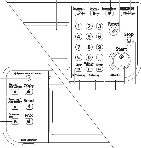
2MW/2MX
(3) Operation panel
|
1 |
2 |
3 |
4 |
5 |
6 |
7 |
8 |
|
14 |
|
9 |
10 |
11 |
12 |
13 |
|
15 |
22 |
23 |
24 |
|
|
16 |
||||
|
17 |
||||
|
18 |
||||
|
19 |
||||
|
20 |
21
|
Figure 1-1-4 |
|||||
|
1. |
Message display |
10. |
Quick No.search key |
17. |
Favorite/Application key / |
|
2. |
Interrupt key / LED |
11. |
Enter key |
LED |
|
|
3. |
Numeric keys |
12. |
Start key / LED |
18. |
Send key / LED |
|
4. |
Logout key / LED |
13. |
Stop key |
19. |
Document box key / LED |
|
5. |
Energy saver / LED |
14. |
System menu/Counter key |
20. |
FAX key / LED |
|
6. |
Reset key |
/ LED |
21. |
Job separator LED |
|
|
7. |
Power key / LED |
15. |
Status/Job cancel / LED |
22. |
Processing LED |
|
8. |
Main power LED |
16. |
Copy key / LED |
23. |
Memory LED |
|
9. |
Clear key |
24. |
Attention LED |
1-1-8

|
2MW/2MX |
|||||
|
1-1-3 |
Machine cross section |
||||
|
15 |
|||||
|
13 |
|||||
|
11 |
|||||
|
10 |
|||||
|
12 |
|||||
|
7 |
|||||
|
6 |
|||||
|
5 |
|||||
|
4 |
|||||
|
3 |
|||||
|
14 |
9 |
1 |
8 |
2 |
|
Light path |
Paper path |
Paper path (option) |
|||
|
Figure 1-1-5 |
|||||
|
1. |
Cassette |
7. |
Drum unit |
13. |
Image scanner unit (ISU) |
|
2. |
Cassette paper feed section |
8. |
Developer unit |
14. |
Laser scanner unit (LSU) |
|
3. |
MP tray paper feed section |
9. |
Toner container |
15. |
Document processor (DP) |
|
4. |
Conveying section |
10. |
Fuser unit |
||
|
5. |
Transfer/Separation section |
11. |
Eject section |
||
|
6. |
Charger roller unit |
12. |
Duplex/conveyning section |
1-1-9

2MW/2MX
This page is intentionally left blank.
1-1-10

2MW/2MX
1-2-1 Installation environment
1.Temperature: 10 to 32.5°C/50 to 90.5°F
2.Humidity: 15 to 80% RH
3.Power supply: 120 V AC, 12.0 A
220 — 240 V AC, 6.5 A
4.Power supply frequency: 50 Hz ±2%/60 Hz ±2%
5.Installation location
Avoid direct sunlight or bright lighting. Ensure that the photoconductor will not be exposed to direct sunlight or other strong light when removing paper jams.
Avoid locations subject to high temperature and high humidity or low temperature and low humidity; an abrupt change in the environmental temperature; and cool or hot, direct air.
Avoid places subject to dust and vibrations.
Choose a surface capable of supporting the weight of the machine.
Place the machine on a level surface (maximum allowance inclination: 1°).
Avoid air-borne substances that may adversely affect the machine or degrade the photoconductor, such as mercury, acidic of alkaline vapors, inorganic gasses, NOx, SOx gases and chlorine-based organic solvents.
Select a well-ventilated location.
6.Allow sufficient access for proper operation and maintenance of the machine.
500 mm
19 11/16”
|
100 mm |
350 mm |
100 mm |
1000 mm |
|
3 15/16” |
13 3/4” |
3 15/16” |
39 3/8” |
Figure 1-2-1
1-2-1

1-2-2 Unpacking and installation
(1) Installation procedure
Start
Unpack
Remove the tapes and spacer
Install the job separator tray
Release the scanner lock lever
Install the optional paper feeder (option)
Load paper
Install the toner container
Install the expansion memory (option)
Switch the cassette heater switch
2MW/2MX
Install the other optional devices
Connect the power cord
Installing toner
Output an own-status report (maintenance item U000)
Exit maintenance mode
Print out the user setting list
Make test copies
Attaching the language label (Excluding 240V AC)
Completion of the machine installation
1-2-2
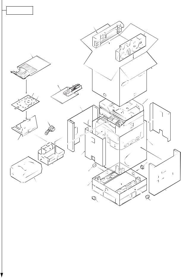
2MW/2MX
Unpacking
l
21
20
11
15
16
5


 24 7
24 7 


14
|
10 |
4 |
|||||
|
23 |
22 |
|||||
|
8 |
22 |
|||||
|
9 |
1 |
|||||
|
3 |
6 |
|||||
|
22 |
2 |
22 |
||||
|
Figure 1-2-2 |
||||||
|
1. |
Bottom case |
9. |
Plastic bag (630 × 730) |
17. CD-ROM *1 |
||
|
2. |
Bottom pad R |
10. |
Spacer B |
18. |
Installation guide, etc. |
|
|
3. |
Bottom pad L |
11. |
Outer case |
19. |
Plastic bag |
|
|
4. |
Machine cover (740 × 700) |
12. |
Upper pad R |
20. |
Job separator tray |
|
|
5. |
Machine |
13. |
Upper pad L |
21. |
Plastic bag (400 × 600) |
|
|
6. |
Inner case R |
14. |
Power cord |
22. |
Hinge joints |
|
|
7. |
Inner case L |
15. |
Toner container |
23. |
Inner case F |
|
|
8. |
Spacer A |
16. |
Plastic bag (400 × 600) |
24. |
Inner case B |
*1 Excluding 230V AC model
Place the machine on a level surface.
1-2-3

2MW/2MX
Remove the tapes and spacer
|
1. Remove four tapes. |
Tape |
Tape
Tape
Tape
Figure 1-2-3
|
2. |
Open the DP top cover. |
DP top cover |
Pad |
|
|
3. |
Slide two DP original width guides and |
|||
|
then remove the pad. |
||||
|
4. |
Close the DP top cover. |
DP original width guide
Figure 1-2-4
1-2-4

5.Open the DP.
6.Remove the protective sheet and paper.
2MW/2MX
DP
Protective sheet
Paper
Figure 1-2-5
7. Remove the tape.
Tape
Figure 1-2-6
1-2-5

2MW/2MX
8. Peel off two protective sheets.
9. Remove the spacer.
Figure 1-2-7
1-2-6
![]()
Install the job separator tray
1.Gently push the job separator tray into the machine along the guides.
Release the scanner lock lever
1.Pull the scanner lock lever in the direction of the arrow. This will unlock the scanner mechanism.
Job separator tray
Figure 1-2-8
Scanner lock lever
Figure 1-2-9
1-2-7

2MW/2MX
Install the optional paper feeder (option)
1. Install the optional paper feeder as required.
Paper feeder
Load paper
1.Pressing the paper width adjusting tab as shown, move the paper width guides to fit the paper size.
Figure 1-2-10
Paper width adjusting tab 
Cassette
Paper width guides
Figure 1-2-11
1-2-8

2MW/2MX
2.Adjust the paper length guide to fit the paper size.
Paper length guides
Figure 1-2-12
|
3. |
Align the paper so that it is abut with the |
Paper |
|
right end of the cassette. |
||
|
4. |
Insert the cassette size plate. |
|
|
5. |
Gently push the cassette back in. |
|
Cassette |
|
Cassette |
|
size plate |
Figure 1-2-13
1-2-9

Install the toner container
1.Open the front cover.
2.Hold the toner container vertically and tap the upper part five times or more. Turn the toner container upside down and tap the upper part five times or more.
3.Shake the toner container up and down five times or more.
Turn the toner container upside down and shake it five times or more.
2MW/2MX
Toner container
Figure 1-2-14
Toner container
Figure 1-2-15
1-2-10

2MW/2MX
4.Shake the toner container approximately five or six times in the horizontal direction to stir toner.
Figure 1-2-16
5. Gently push the toner container into the machine.
Push the container all the way into the machine until it locks in place.
Toner container
Figure 1-2-17
1-2-11

Switch the cassette heater switch
1.Release the hook and then remove the switch cover.
2.Turn the cassette heater switch on.
Note: When the cassette heater is used, it turns it on.
3. Refit the switch cover.
2MW/2MX
Cassette heater switch
Hook
Switch cover
Figure 1-2-18
Install the other optional devices
1.Install the optional devices (Document finisher, Fax kit, etc.) as required.
Connect the power cord
1.Connect the power cord to the connector on the machine.
2.Insert the power plug into the wall outlet.
Installing toner
1.Turn the main power switch on.
The machine automatically starts to feed toner in the developer unit.
Note: When the main power switch is turned on for the first time, it takes about ten minutes until entering the state that can be copied.
2.The drive chain is disengaged when toner installation is completed.
1-2-12

2MW/2MX
Output an own-status report (maintenance item U000)
1.Enter 000 using the numeric keys and press the start key.
2.Select Maintenance and press the start key to output a list of the current settings of the maintenance items.
3.Press the stop key.
Exit maintenance mode
1. Enter “001” using the numeric keys and press the start key.
Print out a user setting list
1. Select [Report Print] to print a user setting list.
Make test copies
1. Place an original and make test copies.
Attaching the language label (Excluding 240V AC)
1. Attach the corresponding language label as required.
Installation is completed.
(2) Setting initial copy modes
Factory settings are as follows:
|
Maintenance |
Contents |
Factory setting |
|
|
item No. |
|||
|
U253 |
Switching between double and single counts |
Double count |
|
|
(A3/Ledger) |
|||
|
U260 |
Selecting the timing for copy counting |
Eject |
|
|
U285 |
Setting service status page |
On |
|
|
U326 |
Setting the black line cleaning indication |
On/8 |
|
|
U343 |
Switching between duplex/simplex copy mode |
Off |
|
1-2-13

2MW/2MX
1-2-3 Install the expansion memory (option)
Procedure
1.Turn off the main power switch. Caution: Do not insert or remove expansion memory while machine power is on.
Doing so may cause damage to the machine and the expansion memory.
2.Remove the controller box cover.
3.Remove two screws.
Hook
Hook
Contoroler box cover
Figure 1-2-19
|
4. |
Remove the memory slot cover. |
Memory slot cover |
|
|
5. |
Insert the expansion memory into the |
||
|
memory socket so that the notches on |
|||
|
the memory align with the correspond- |
|||
|
ing protrusions in the slot. |
|||
|
6. |
Refit the memory slot cover. |
||
|
7. |
Refit the screw. |
||
|
8. |
Refit the controller box cover. |
Expansion memory |
|
|
9. |
Print a status page to check the mem- |
||
|
ory expansion. |
|||
|
If memory expansion has been properly |
|||
|
performed, information on the installed |
|||
|
memory is printed with the total memory |
|||
|
capacity has been increased. Standard |
|||
|
memory capacity 1 GB. |
Memory socket
Figure 1-2-20
1-2-14

2MW/2MX
1-2-4 Option composition
DF-470 (500 sheets) (Document finisher)
AK-470 (Bridge unit)
PF-790 (500 sheets x 1) (Paper feeder + Cabinet)
PF-471 (500 sheets x 2) (Paper feeder)
|
IB-50 |
USB key board |
|
(Gigabit ethernet board) |
|
|
FAX System(U) |
RAM Memory |
|
UG-33 |
|
|
ThinPrint Activation Kit |
Card Authentication Kit (B)
1-2-15

2MW/2MX
This page is intentionally left blank.
1-2-16
![]()
2MW/2MX
1-3-1 Maintenance mode
The machine is equipped with a maintenance function which can be used to maintain and service the machine.
(1) Executing a maintenance item
Start
Press the status/Job cancel key.
Enter “10871087” using the numeric keys.
Enter the maintenance item number using the cursor left/right keys
or numeric keys.
Press the start key.
The selected maintenance item is run.
Press the stop key.
|
Yes |
Repeat the same |
|
|
maintenance item? |
||
|
No |
||
Yes
Run another maintenance item?
No
Enter “001” using the cursor left/right keys or numeric keys and press the start key.
Maintenance mode is entered.
The maintenance item is selected.
Maintenance mode is exited.
End
1-3-1
|
2MW/2MX |
||||
(2) Maintenance modes item list |
||||
|
Section |
Item |
Content of maintenance item |
Initial |
|
|
No. |
setting |
|||
|
General |
U000 |
Outputting an own-status report |
— |
|
|
U001 |
Exiting the maintenance mode |
— |
||
|
U002 |
Setting the factory default data |
— |
||
|
U004 |
Setting the machine number |
— |
||
|
U019 |
Displaying the ROM version |
— |
||
|
Initialization |
U021 |
Memory initializing |
— |
|
|
Drive, paper |
U030 |
Checking the operation of the motors |
— |
|
|
feed and |
||||
|
U031 |
Checking switches and sensors for paper conveying |
— |
||
|
paper con- |
||||
|
U032 |
Checking the operation of the clutches |
— |
||
|
veying sys- |
||||
|
tem |
U033 |
Checking the operation of the solenoids |
— |
|
|
U034 |
Adjusting the print start timing |
|||
|
Leading edge registration |
0/0/0 |
|||
|
Center line |
0/0/0/0/0 |
|||
|
U035 |
Setting the printing area for folio paper |
330/210 |
||
|
U037 |
Checking the operation of the fan motors |
— |
||
|
U051 |
Adjusting the deflection in the paper |
0/0/0/0 |
||
|
U053 |
Setting the adjustment of the motor speed |
-2/-2/-6/0/0 |
||
|
Optical |
U063 |
Adjusting the shading position |
0 |
|
|
U065 |
Adjusting the scanner magnification |
0/0 |
||
|
U066 |
Adjusting the scanner leading edge registration |
0/0 |
||
|
U067 |
Adjusting the scanner center line |
0/0 |
||
|
U068 |
Adjusting the scanning position for originals from the DP |
0/0 |
||
|
U070 |
Adjusting the DP magnification |
0/0 |
||
|
U071 |
Adjusting the DP scanning timing |
0/0/0/0 |
||
|
U072 |
Adjusting the DP center line |
0/0 |
||
|
U089 |
Outputting a MIP-PG pattern |
— |
||
|
U099 |
Adjusting original size detection |
40/30/20/19 |
||
|
50/50/50/49 |
||||
|
(when DP is installed) |
||||
1-3-2
|
2MW/2MX |
||||
|
Section |
Item |
Content of maintenance item |
Initial |
|
|
No. |
setting |
|||
|
High voltage |
U100 |
Setting the main high voltage |
-/-/0/0 |
|
|
-/-/1800 |
||||
|
off |
||||
|
U101 |
Setting the voltage for the primary transfer |
0/0/0/0/190/650/900 |
||
|
1100/450/650/750 |
||||
|
U108 |
Setting separation shift bias |
4 |
||
|
U111 |
Checking the drum drive time |
— |
||
|
U118 |
Displaying the drum history |
— |
||
|
U127 |
Checking/clearing the transfer count |
0/0 |
||
|
Developer |
U139 |
Displaying the temperature and humidity outside the |
— |
|
|
machine |
||||
|
U140 |
Displaying developer bias |
170/2700/60 |
||
|
U147 |
Setting for toner applying operation |
Mode1 |
||
|
U150 |
Checking sensors for toner |
— |
||
|
U157 |
Checking the developer drive time |
— |
||
|
Fuser |
U161 |
Setting the fuser control temperature |
135/150/165/175/1/1 |
|
|
U199 |
Displaying fuser heater temperature |
— |
||
|
Operation |
U201 |
Initializing the touch panel |
— |
|
|
panel and |
||||
|
U203 |
Checking DP operation |
— |
||
|
support |
||||
|
U207 |
Checking the operation panel keys |
— |
||
|
equipment |
||||
|
U222 |
Setting the IC card type |
Other |
||
|
U243 |
Checking the operation of the DP motors |
— |
||
|
U244 |
Checking the DP switches |
— |
||
|
Mode setting |
U250 |
Checking/clearing the maintenance cycle |
300000/0 |
|
|
U251 |
Checking/clearing the maintenance counter |
0/0 |
||
|
U252 |
Setting the destination |
— |
||
|
U253 |
Switching between double and single counts |
Double count |
||
|
(A3/Ledger) |
||||
|
U260 |
Selecting the timing for copy counting |
Eject |
||
|
U265 |
Setting OEM purchaser code |
— |
||
|
U285 |
Setting service status page |
On |
||
|
U326 |
Setting the black line cleaning indication |
On/8 |
||
|
U332 |
Setting the size conversion factor |
1.0 |
||
|
U341 |
Specific paper feed location setting for printing function |
Off/Off/Off |
||
|
U343 |
Switching between duplex/simplex copy mode |
Off |
||
|
U345 |
Setting the value for maintenance due indication |
0 |
||
1-3-3
|
2MW/2MX |
||||
|
Section |
Item |
Content of maintenance item |
Initial |
|
|
No. |
setting |
|||
|
Image |
U402 |
Adjusting margins of image printing |
3.0/2.5/2.5/5.0 |
|
|
processing |
||||
|
U403 |
Adjusting margins for scanning an original on the contact |
2.0/2.0/2.0/2.0 |
||
|
glass |
||||
|
U404 |
Adjusting margins for scanning an original from the DP |
3.0/2.5/3.0/4.0 |
||
|
U407 |
Adjusting the leading edge registration for memory image |
0 |
||
|
printing |
||||
|
U411 |
Adjusting the scanner automatically |
— |
||
|
U425 |
Setting the target |
— |
||
|
U432 |
Setting the center offset for the exposure |
0/0/0 |
||
|
Image |
U470 |
Setting the JPEG compression ratio |
85/85 |
|
|
processing |
Copy |
85/85 |
||
|
Send |
15/25/60/15/25/60 |
|||
|
System |
30/40/51/70/90/ |
|||
|
30/40/51/70/90 |
||||
|
30/40/51/70/90/ |
||||
|
30/40/51/70/90 |
||||
|
90/90 |
||||
|
Fax |
U600 |
Initializing all data |
— |
|
|
U601 |
Initializing permanent data |
— |
||
|
U603 |
Setting user data 1 |
DTMF |
||
|
U604 |
Setting user data 2 |
2 (120V) |
||
|
1 (220-240V) |
||||
|
U605 |
Clearing data |
— |
||
|
U610 |
Setting system 1 |
0 |
||
|
Setting the number of lines to be ignored when receiving |
||||
|
a fax at 100% magnification |
3 |
|||
|
Setting the number of lines to be ignored when receiving |
||||
|
a fax in the auto reduction mode |
0 |
|||
|
Setting the number of lines to be ignored when receiving |
||||
|
a fax (A4R/LetterR) in the auto reduction mode |
||||
|
U611 |
Setting system 2 |
7 |
||
|
Setting the number of adjustment lines for automatic |
||||
|
reduction |
22 |
|||
|
Setting the number of adjustment lines for automatic |
||||
|
reduction when A4 paper is set |
26 |
|||
|
Setting the number of adjustment lines for automatic |
||||
|
reduction when letter size paper is set |
||||
|
U612 |
Setting system 3 |
|||
|
Selecting if auto reduction in the auxiliary direction is to |
On |
|||
|
be performed |
||||
|
Setting the automatic printing of the protocol list |
Off |
|||
|
U615 |
Setting system 6 |
Ledger |
||
|
U620 |
Setting the remote switching mode |
One |
||
1-3-4
|
2MW/2MX |
||||
|
Section |
Item |
Content of maintenance item |
Initial |
|
|
No. |
setting |
|||
|
Fax |
U625 |
Setting the transmission system 1 |
||
|
Setting the auto redialing interval |
3 (120 V) |
|||
|
2 (220-240 V) |
||||
|
Setting the number of times of auto redialing |
2 (120 V) |
|||
|
3 (220-240 V) |
||||
|
U630 |
Setting communication control 1 |
14400bps/V17 |
||
|
Setting the communication starting speed |
||||
|
Setting the reception speed |
14400bps |
|||
|
Setting the waiting period to prevent echo problems at |
300 |
|||
|
the sender |
75 |
|||
|
Setting the waiting period to prevent echo problems at |
||||
|
the receiver |
||||
|
U631 |
Setting communication control 2 |
|||
|
Setting ECM transmission |
On |
|||
|
Setting ECM reception |
On |
|||
|
Setting the frequency of the CED signal |
2100 |
|||
|
U632 |
Setting communication control 3 |
Off |
||
|
Setting the DIS signal to 4 bytes |
||||
|
Setting the CNG detection times in the fax/telephone auto |
2Time |
|||
|
select mode |
||||
|
U633 |
Setting communication control 4 |
On |
||
|
Enabling/disabling V.34 communication |
||||
|
Setting the number of times of DIS signal reception |
On |
|||
|
Setting the number of times of DIS signal reception |
Once |
|||
|
Setting the reference for RTN signal output |
15% |
|||
|
U634 |
Setting communication control 5 |
0 |
||
|
U640 |
Setting communication time 1 |
7 |
||
|
Setting the one-shot detection time for remote switching |
||||
|
Setting the continuous detection time for remote switch- |
80 |
|||
|
ing |
||||
|
U641 |
Setting communication time 2 |
56 |
||
|
Setting the T0 time-out time |
||||
|
Setting the T1 time-out time |
36 |
|||
|
Setting the T2 time-out time |
69 |
|||
|
Setting the Ta time-out time |
30 |
|||
|
Setting the Tb1 time-out time |
20 |
|||
|
Setting the Tb2 time-out time |
80 |
|||
|
Setting the Tc time-out time |
60 |
|||
|
Setting the Td time-out time |
9 (120 V) |
|||
|
6 (220-240 V) |
||||
|
U650 |
Setting modem 1 |
0dB |
||
|
Setting the G3 transmission cable equalizer |
||||
|
Setting the G3 reception cable equalizer |
0dB |
|||
|
Setting the modem detection level |
-43dBm |
|||
1-3-5
|
2MW/2MX |
||||
|
Section |
Item |
Content of maintenance item |
Initial |
|
|
No. |
setting |
|||
|
Fax |
U651 |
Setting modem 2 |
||
|
Modem output level |
-11 (120 V) |
|||
|
-11 (220-240 V) |
||||
|
DTMF output level (main value) |
6 (120 V) |
|||
|
8 (220-240 V) |
||||
|
DTMF output level (level difference) |
2 (120 V) |
|||
|
2 (220-240 V) |
||||
|
U660 |
Setting the NCU |
PSTN |
||
|
Setting the connection to PBX/PSTN |
||||
|
Setting PSTN dial tone detection |
On |
|||
|
Setting busy tone detection |
On |
|||
|
Setting for a PBX |
Loop |
|||
|
Setting the loop current detection before dialing |
On |
|||
|
U670 |
Outputting lists |
— |
||
|
U695 |
FAX function customize |
On/Off |
||
|
U699 |
Setting the software switches |
— |
||
|
Others |
U901 |
Checking copy counts by paper feed locations |
0/0/0/0/0 |
|
|
U903 |
Checking/clearing the paper jam counts |
0/0 |
||
|
U904 |
Checking/clearing the call for service counts |
0/0 |
||
|
U905 |
Checking counts by optional devices |
0/0/0/0 |
||
|
U910 |
Clearing the print coverage data |
0 |
||
|
U917 |
Setting backup data reading/writing |
— |
||
|
U927 |
Clearing the all copy counts and machine life counts (one |
— |
||
|
time only) |
||||
|
U935 |
Relay board maintenance |
— |
||
|
U942 |
Setting of deflection for feeding from DP |
0/0 |
||
|
U977 |
Data capture mode |
— |
||
|
U984 |
Checking the developing unit number |
— |
||
|
U985 |
Displaying the developer history |
— |
||
1-3-6

2MW/2MX
(3) Contents of the maintenance mode items
|
Item No. |
Description |
|
U000 Outputting an own-status report |
Description
Outputs lists of the current settings of the maintenance items and paper jam and service call occurrences. Outputs the event log. Also sends output data to the USB memory.
Purpose
To check the current setting of the maintenance items, or paper jam or service call occurrences. Before initializing or replacing the backup RAM, output a list of the current settings of the maintenance items to reenter the settings after initialization or replacement.
Method
1.Press the start key.
2.Select the item to be output using the cursor up/down keys.
3.Select On or Off using the cursor left/right keys or numeric keys.
|
Display |
Output list |
|
Maintenance |
List of the current settings of the maintenance modes |
|
Event |
Outputs the event log |
|
All |
Outputs the all reports |
4. Press the start key. A list is output.
Method: Send to the USB memory
1.Press the power key on the operation panel, and after verifying the main power indicator has gone off, switch off the main power switch.
2.Insert USB memory in USB memory slot.
3.Turn the main power switch on.
4.Enter the maintenance item.
5.Press the start key.
6.Select the item to be send.
7.Select [Text] or [HTML].
|
Display |
Output list |
|
|
Outputs the report |
|
USB (Text) |
Sends output data to the USB memory (text type) |
|
USB (HTML) |
Sends output data to the USB memory (HTML type) |
8.Press the start key.
Output will be sent to the USB memory.
Completion
Press the stop key. The screen for selecting a maintenance item No. is displayed.
1-3-7

|
2MW/2MX |
|||||||||||||
|
Item No. |
Description |
||||||||||||
|
U000 |
Event log |
||||||||||||
|
Event Log |
|||||||||||||
|
MFP |
(2) 04/Sep/2010 08:40 |
||||||||||||
|
(1) Firmware version 2K3_2000.000.000 |
(3) |
(4) |
(5) |
||||||||||
|
2010.09.04 |
[XXXXXXXX] |
[XXXXXXXX] |
[XXXXXXXX] |
||||||||||
|
(7) Paper Jam Log |
(8) |
Service Call Log |
|||||||||||
|
# |
Count. |
Event Descriprions |
# |
Count. |
Service Code |
||||||||
|
16 |
1876543 |
0501.01.08.01.01 |
8 |
1881214 |
01.6000 |
||||||||
|
15 |
166554 |
4002.01.08.01.01 |
7 |
178944 |
01.2100 |
||||||||
|
14 |
4988 |
0501.01.08.01.01 |
6 |
5296 |
01.4000 |
||||||||
|
13 |
4988 |
4002.01.08.01.01 |
5 |
5295 |
01.6000 |
||||||||
|
12 |
4988 |
0501.01.08.01.01 |
4 |
2099 |
01.2100 |
||||||||
|
11 |
4988 |
4002.01.08.01.01 |
3 |
1054 |
01.4000 |
||||||||
|
10 |
1103 |
0501.01.08.01.01 |
2 |
809 |
01.6000 |
||||||||
|
9 |
1103 |
4002.01.08.01.01 |
1 |
30 |
01.2100 |
||||||||
|
8 |
1103 |
0501.01.08.01.01 |
(9) |
Maintenance Log |
|||||||||
|
7 |
1103 |
4002.01.08.01.01 |
|||||||||||
|
# |
Count. |
Item |
|||||||||||
|
6 |
1027 |
0501.01.08.01.01 |
|||||||||||
|
8 |
1045571 |
01.00 |
|||||||||||
|
5 |
1027 |
4002.01.08.01.01 |
|||||||||||
|
7 |
104511 |
01.00 |
|||||||||||
|
4 |
1027 |
0501.01.08.01.01 |
|||||||||||
|
6 |
7045 |
01.00 |
|||||||||||
|
3 |
1027 |
4002.01.08.01.01 |
|||||||||||
|
5 |
3454 |
01.00 |
|||||||||||
|
2 |
406 |
0501.01.08.01.01 |
|||||||||||
|
4 |
3454 |
01.01 |
|||||||||||
|
1 |
36 |
4002.01.08.01.01 |
|||||||||||
|
3 |
3454 |
01.01 |
|||||||||||
|
2 |
417 |
01.01 |
|||||||||||
|
0501.01.08.01.01 |
1 |
34 |
01.01 |
||||||||||
|
(10) Unknown toner Log |
|||||||||||||
|
(a) |
(b) |
(c) |
(d) |
(e) |
# |
Count. |
Item |
||||||
|
5 |
3454 |
01.00 |
|||||||||||
|
4 |
3454 |
01.00 |
|||||||||||
|
3 |
3454 |
01.00 |
|||||||||||
|
2 |
406 |
01.00 |
|||||||||||
|
1 |
32 |
01.00 |
|||||||||||
|
(11) Counter Log |
|||||||||||||
|
(f) J0100: 0 |
J0511: 0 |
J4201: 0 |
(g) C0030: 1 |
C2000: 1 |
(h) T00: 1 |
||||||||
|
J0101: 0 |
J0512: 0 |
J4202: 0 |
C0070: |
1 |
C2010: |
1 |
T01: |
1 |
|||||
|
J0104: 0 |
J0513: 0 |
J4203: 0 |
C0100: |
1 |
C2600: |
1 |
|||||||
|
J0106: 0 |
J0518: 0 |
J4208: 0 |
C0120: |
1 |
C3100: |
1 |
|||||||
|
J0107: 0 |
J0519: 0 |
J4209: 0 |
C0130: |
1 |
C3200: |
1 |
|||||||
|
. |
. |
. |
. |
. |
|||||||||
|
. |
. |
. |
. |
. |
|||||||||
|
. |
. |
. |
. |
. |
|||||||||
|
. |
. |
. |
. |
. |
|||||||||
|
. |
. |
. |
. |
. |
|||||||||
|
. |
. |
. |
. |
. |
|||||||||
|
(6) [XXXXXXXXXXXXXXXX] |
|||||||||||||
|
Figure 1-3-1 |
|||||||||||||
|
1-3-8 |

2MW/2MX
|
Item No. |
Description |
||||||
|
U000 Detail of event log |
|||||||
|
No. |
Items |
Description |
|||||
|
(1) |
System version |
||||||
|
(2) |
System date |
||||||
|
(3) |
Engine soft version |
||||||
|
(4) |
Engine boot version |
||||||
|
(5) |
Operation panel mask version |
||||||
|
(6) |
Machine serial number |
||||||
|
(7) |
Paper Jam # |
Count. |
Event |
||||
|
Log |
|||||||
|
Remembers 1 to 16 of |
The total page count |
Log code (hexadeci- |
|||||
|
occurrence. If the occur- |
at the time of the |
mal, 5 categories) |
|||||
|
rence of the previous |
paper jam. |
(a) Cause of a paper |
|||||
|
paper jam is less than |
|||||||
|
16, all of the paper jams |
jam |
||||||
|
are logged. When the |
(b) Paper source |
||||||
|
occurrence excesseds |
(c) Paper size |
||||||
|
16, the oldest occur- |
(d) Paper type |
||||||
|
rence is removed. |
(e) Paper eject |
||||||
|
(a) Cause of paper jam (Hexadecimal) |
Refer to P.1-4-1 for paper jam location 0000: Initial jam
0100: Secondary paper feed request time out 0101: Waiting for process package to be ready 0104: Waiting for conveying package to be ready
0106: Paper feeding request for duplex printing time out 0107: Waiting for fuser package to be ready
0110: Right cover open 0111: Front cover open
0120: Receiving a duplex paper feeding request while paper is empty 0121: Exceeding number of duplex pages circulated
0210: Right lower cover open
0501: No paper feed from cassette 1 0502: No paper feed from cassette 2 0503: No paper feed from cassette 3 0508: No paper feed from duplex section 0509: No paper feed from MP tray
0511: Multiple sheets in cassette 1 0512: Multiple sheets in cassette 2 0513: Multiple sheets in cassette 3 0518: Multiple sheets in duplex section 0519: Multiple sheets in MP tray
1403: PF feed sensor 1 non arrival jam 1413: PF feed sensor 1 stay jam
4002: Registration sensor non arrival jam (cassette 2) 4003: Registration sensor non arrival jam (cassette 3)
1-3-9
2MW/2MX
|
Item No. |
Description |
||||
|
U000 |
|||||
|
No. |
Items |
Description |
|||
|
(7) |
Paper Jam |
4012: Registration sensor stay jam (cassette 2) |
|||
|
cont. |
Log |
4013: Registration sensor stay jam (cassette 3) |
|||
|
4201: Eject sensor non arrival jam (cassette 1) |
|||||
|
4202: Eject sensor non arrival jam (cassette 2) |
|||||
|
4203: Eject sensor non arrival jam (cassette 3) |
|||||
|
4208: Eject sensor non arrival jam (duplex) |
|||||
|
4209: Eject sensor non arrival jam (Mp tray) |
|||||
|
4211: Eject sensor stay jam (cassette 1) |
|||||
|
4212: Eject sensor stay jam (cassette 2) |
|||||
|
4213: Eject sensor stay jam (cassette 3) |
|||||
|
4218: Eject sensor stay jam (duplex) |
|||||
|
4219: Eject sensor stay jam (MP tray) |
|||||
|
4301: Duplex sensor non arrival jam (cassette 1) |
|||||
|
4302: Duplex sensor non arrival jam (cassette 2) |
|||||
|
4303: Duplex sensor non arrival jam (cassette 3) |
|||||
|
4309: Duplex sensor non arrival jam (MP tray) |
|||||
|
4311: Duplex sensor stay jam (cassette 1) |
|||||
|
4312: Duplex sensor stay jam (cassette 2) |
|||||
|
4313: Duplex sensor stay jam (cassette 3) |
|||||
|
4319: Duplex sensor stay jam (MP tray) |
|||||
|
4901: Bridge conveying sensor 1 non arrival jam (cassette 1) |
|||||
|
4902: Bridge conveying sensor 1 non arrival jam (cassette 2) |
|||||
|
4903: Bridge conveying sensor 1 non arrival jam (cassette 3) |
|||||
|
4908: Bridge conveying sensor 1 non arrival jam (duplex) |
|||||
|
4909: Bridge conveying sensor 1 non arrival jam (MP tray) |
|||||
|
4911: Bridge conveying sensor 1 stay jam (cassette 1) |
|||||
|
4912: Bridge conveying sensor 1 stay jam (cassette 2) |
|||||
|
4913: Bridge conveying sensor 1 stay jam (cassette 3) |
|||||
|
4918: Bridge conveying sensor 1 stay jam (duplex) |
|||||
|
4919: Bridge conveying sensor 1 stay jam (MP tray) |
|||||
|
5001: Bridge conveying sensor 3 non arrival jam (cassette 1) |
|||||
|
5002: Bridge conveying sensor 3 non arrival jam (cassette 2) |
|||||
|
5003: Bridge conveying sensor 3 non arrival jam (cassette 3) |
|||||
|
5008: Bridge conveying sensor 3 non arrival jam (duplex) |
|||||
|
5009: Bridge conveying sensor 3 non arrival jam (MP tray) |
|||||
|
5011: Bridge conveying sensor 3 stay jam (cassette 1) |
|||||
|
5012: Bridge conveying sensor 3 stay jam (cassette 2) |
|||||
|
5013: Bridge conveying sensor 3 stay jam (cassette 3) |
|||||
|
5018: Bridge conveying sensor 3 stay jam (duplex) |
|||||
|
5019: Bridge conveying sensor 3 stay jam (MP tray) |
|||||
|
6023: Staple cover open |
|||||
|
6043: DF top cover open6103: DF paper conveying sensor non arrival |
|||||
|
jam |
|||||
|
6113: DF paper conveying sensor stay jam |
|||||
|
6123: DF paper conveying sensor remaining jam |
|||||
|
6413: DF eject paper sensor stay jam |
|||||
|
6423: DF eject paper sensor remaining jam |
|||||
|
6803: Front adjustment plate operation ON error |
|||||
1-3-10
 Loading…
SpecificationsInstallationMaintenanceTroubleshootingAssembly and disassemblyMechanical and eletrical constructionOperation of the PWBs
-
SERVICEMANUAL
Published in September 20132MWSM065
Rev.5
FS-6525MFPFS-6530MFP
-
CAUTION
RISK OF EXPLOSION IF BATTERY IS REPLACED BY AN INCORRECT TYPE.
DISPOSE OF USED BATTERIES ACCORDING TO THE INSTRUCTIONS.It may be illegal to dispose of this battery into the municipal
waste stream. Check with your local solid waste officials for
details in your area for proper disposal.IL Y A UN RISQUE DDE TYPE INCORRECINSTRUCTIONS DON
Il peut tre illgal de jefonctionnaires municipet une mise au
rebut aATTENTIONEXPLOSION SI LA BATTERIE EST REMPLACEE PAR UN MODELE T. METTRE
AU REBUT LES BATTERIES UTILISEES SELON LES NEES.ter les batteries dans des eaux dgout municipales. Vrifiez avec
les aux de votre rgion pour les dtails concernant des dchets
solides pproprie. -
Revision history
Revision Date Replaced pages Remarks
1 20 June 2012 1-3-12, 1-4-20, Address —
2 20 August 2012 1-3-65, 1-3-121, 1-3-122, 2-4-12 —
3 1 December 2012 Contents, 1-6-2, 2-4-9 —
4 14 February 2013 Contents, 1-4-19, 1-4-20, 2-4-11 to 21,
Address —5 17 September 2013 Contents, 1-1-8, 1-3-3, 1-3-60 —
-
This page is intentionally left blank.
-
Saf
This booklet provides satheir customers, their maare advised to
read this described here before eety precautionsfety warnings and precautions for our service personnel to
ensure the safety of chines as well as themselves during
maintenance activities. Service personnelbooklet carefully to familiarize themselves with the warnings
and precautions ngaging in maintenance activities. -
Safety warnings and precautions
Various symbols are used to protect our service personnel and
customers from physical danger and to prevent damage to their
property. These symbols are described below:DANGER: High risk of serious bodily injury or death may result
from insufficient attention to or incorrect compliance with warning
messages using this symbol.WARNING: Serious bodily injury or death may result from
insufficient attention to or incorrect compliance with warniCAUTION: Bodily injupliance wi
Symbols
The triangle ( ) symbol ishown inside the symbol.
General warnin
Warning of high
indicates a prohibited a
General prohib
indicates that action is
General action
Always ground ng messages using this symbol.
ry or damage to property may result from insufficient attention
to or incorrect com-th warning messages using this symbol.ndicates a warning including danger and caution. The specific
point of attention isg. Warning of risk of electric shock.
temperature.
ction. The specific prohibition is shown inside the symbol.
ited action. Disassembly prohibited.
required. The specific action required is shown inside the
symbol.required. Remove the power plug from the wall outlet.
the copier.
-
1. Installation Precautions
WARNING
Do not use a power supply with a voltage other than that
specified. Avoid multiple connections to one outlet: they may cause
fire or electric shock. When using an extension cable, always check
that it is adequate for the rated current.
………………………………………………………………………………………..Connect the ground wire to a suitable grounding point. Not
grounding the copier may cause fire or electric shock. Connecting
the earth wire to an object not approved for the purpose may cause
explosion or electric shock. Never connect the ground cable to any
of the following: gas pipes, light-ning rods, ground cables for
telephone lines and water pipes or faucets not approved by the
proper authorities. ………………..CAUTION:
Do not place the copier o
Do not install the copier
Do not install the copier may cause fire. ………….
Allow sufficient space aras possible. Insufficient
Always handle the mach
Always use anti-topplingthe copier to move unex
Avoid inhaling toner or dingested, drink a lot of wIf it gets
into the eyes, rintion. ………………………….Advice customers that thinstruction handbook.
………………………………………………………………………………………………………….n an infirm or angled surface: the copier may tip over, causing
injury. ………in a humid or dusty place. This may cause fire or electric
shock. ……………..near a radiator, heater, other heat source or near flammable
material. This
……………………………………………………………………………………………………….ound the copier to allow the ventilation grills to keep the
machine as cool ventilation may cause heat buildup and poor copying
performance. …………ine by the correct locations when moving it.
………………………………………….and locking devices on copiers so equipped. Failure to do this
may cause pectedly or topple, leading to injury.
……………………………………………………..eveloper excessively. Protect the eyes. If toner or developer is
accidentally ater to dilute it in the stomach and obtain medical
attention immediately. se immediately with copious amounts of water
and obtain medical atten-……………………………………………………………………………………………………….
ey must always follow the safety warnings and precautions in the
copiers
………………………………………………………………………………………………………. -
2. Precautions for Maintenance
WARNING
Always remove the power plug from the wall outlet before
starting machine disassembly. …………….Always follow the procedures for maintenance described in the
service manual and other related brochures.
…………………………………………………………………………………………………………………………Under no circumstances attempt to bypass or disable safety
features including safety mechanisms and protective circuits.
…………………………………………………………………………………………………………Always use parts having
Always use the thermostwhen replacing them. Usdent.
………………………..When the service manuapart, always use the corr
Always check that the co
Check that the power cais dirty, clean it to remov
Never attempt to disassedamage eyesight. ………
Handle the charger sectshock if handled imprope
CAUTION
Wear safe clothing. If wesecured so they will not
Use utmost caution whe
Handle the fixing section
Check that the fixing uniabnormally high tempera the correct
specifications.
………………………………………………………………….at or thermal fuse specified in the service manual or other
related brochure ing a piece of wire, for example, could lead to
fire or other serious acci-……………………………………………………………………………………………………….
l or other serious brochure specifies a distance or gap for
installation of a ect scale and measure carefully.
…………………………………………………………pier is correctly connected to an outlet with a ground
connection. ……………ble covering is free of damage. Check that the power plug is
dust-free. If it e the risk of fire or electric shock.
………………………………………………………..mble the optical unit in machines using lasers. Leaking laser
light may
……………………………………………………………………………………………………….ions with care. They are charged to high potentials and may
cause electric rly.
…………………………………………………………………………………………………aring loose clothing or accessories such as ties, make sure they
are safely be caught in rotating sections.
…………………………………………………………….n working on a powered machine. Keep away from chains and belts.
……….with care to avoid burns as it can be extremely hot.
…………………………….t thermistor, heat and press rollers are clean. Dirt on them can
cause tures.
…………………………………………………………………………………………….. -
Do not remove the ozone filter, if any, from the copier except
for routine replacement. ………………….Do not pull on the AC power cord or connector wires on
high-voltage components when removing them; always hold the plug
itself.
…………………………………………………………………………………………..Do not route the power cable where it may be stood on or
trapped. If necessary, protect it with a cable cover or other
appropriate item.
……………………………………………………………………………………Treat the ends of the wire carefully when installing a new
charger wire to avoid electric leaks. ……….Remove toner complete
Run wire harnesses care
After maintenance, alwaremoved, have been refitrapped wire and
missingCheck that all the cautiohandbook are clean and
Handle greases and solv Use only a small amou Ventilate the room
well Allow applied solvents switch on. Always wash hands aftNever dispose of toner ofire in a furnace, etc. …..
Should smoke be seen cately. ………………………..
3. Miscellaneous
WARNING
Never attempt to heat thspecified refiner; it may g
Keep the machine awaymight occur. ………………ly from
electronic components.
……………………………………………………………fully so that wires will not be trapped or damaged.
………………………………..ys check that all the parts, screws, connectors and wires that
were tted correctly. Special attention should be paid to any
forgotten connector, screws.
………………………………………………………………………………………….n labels that should be present on the machine according to the
instruction not peeling. Replace with new ones if necessary.
…………………………………ents with care by following the instructions below:
………………………………..nt of solvent at a time,
being careful not to spill. Wipe spills off completely. while using
grease or solvents.to evaporate completely before refitting the
covers or turning the powererwards.
r toner bottles in fire. Toner may cause sparks when exposed
directly to
……………………………………………………………………………………………………….oming from the copier, remove the power plug from the wall
outlet
immedi-……………………………………………………………………………………………………….e drum or expose it to any organic solvents such as alcohol,
other than the enerate toxic gas.
…………………………………………………………………………….from flammable liquids, gases, and aerosols. A fire or an
electric shock
………………………………………………………………………………………………………. -
This page is intentionally left blank.
-
2MW/2MX-5
CONTENTS
1-1 Specifications1-1-1 Specifications
…………………………………………………………………………………………………………
1-1-11-1-2 Parts names
…………………………………………………………………………………………………………..
1-1-5(1) Machine (front
side)…………………………………………………………………………………………….
1-1-5(2) Machine (rear
side)……………………………………………………………………………………………..
1-1-7(3) Operation panel
………………………………………………………………………………………………….
1-1-81-1-3 Machine cross section
……………………………………………………………………………………………..
1-1-91-2 Installation1-2-1 Installation
environment……………………………………………………………………………………………
1-2-11-2-2 Unpacking a(1) Installatio(2) Setting in
1-2-3 Install the ex1-2-4 Option comp
1-3 Maintenance M1-3-1 Maintenance
(1) Executing(2) Maintena(3) Contents
1-3-2 Service mod(1) Printing th(2) Executing(3) Descriptio
1-4 Troubleshooting1-4-1 Paper misfee
(1) Paper mis(2) Paper mis
1-4-2 Self-diagnos(1) Self-diagn(2) Self diagn
1-4-3 Image forma(1) No image(2) No image(3) Image is (4) The
back(5) White stre(6) Black stre(7) Streaks a(8) One side (9) Spots
are(10) Image is (11) The leadi(12) The leadi(13) Paper is w(14)
Offset occ(15) Part of im(16) Fusing is nd
installation………………………………………………………………………………………..
1-2-2n procedure
………………………………………………………………………………………….
1-2-2itial copy
modes…………………………………………………………………………………..
1-2-13pansion memory
(option)………………………………………………………………………
1-2-14osition………………………………………………………………………………………………..
1-2-15ode mode
………………………………………………………………………………………………….
1-3-1 a maintenance item
……………………………………………………………………………..
1-3-1nce modes item list
………………………………………………………………………………..
1-3-2of the maintenance mode items
………………………………………………………………
1-3-7e………………………………………………………………………………………………………
1-3-111e service status page
………………………………………………………………………..1-3-111
a service mode
………………………………………………………………………………..1-3-118n
of service mode
……………………………………………………………………………..1-3-118d
detection…………………………………………………………………………………………..
1-4-1feed indication
……………………………………………………………………………………..
1-4-1feed detection condition
………………………………………………………………………..
1-4-1tic function
……………………………………………………………………………………………
1-4-7ostic function
……………………………………………………………………………………….1-4-7ostic
codes…………………………………………………………………………………………..
1-4-7tion
problems………………………………………………………………………………………
1-4-21 appears (entirely
white)……………………………………………………………………….
1-4-22 appears (entirely
black)……………………………………………………………………….
1-4-22too light.
……………………………………………………………………………………………..
1-4-23ground is colored.
………………………………………………………………………………..
1-4-23aks are printed
vertically………………………………………………………………………
1-4-23aks are printed vertically.
……………………………………………………………………..
1-4-24re printed horizontally.
………………………………………………………………………….
1-4-24of the print image is darker than the other.
…………………………………………….. 1-4-24
printed.
……………………………………………………………………………………………..
1-4-25blurred………………………………………………………………………………………………..
1-4-25ng edge of the image is consistently misaligned with the
original. ……………… 1-4-25ng edge of the image is
sporadically misaligned with the original. ………………
1-4-25rinkled.
……………………………………………………………………………………………..
1-4-26urs.
…………………………………………………………………………………………………..
1-4-26age is missing.
……………………………………………………………………………………
1-4-26loose………………………………………………………………………………………………….
1-4-26 -
2MW/2MX
(17) Image is out of focus.
………………………………………………………………………………………..1-4-27(18)
Image center does not align with the original center.
…………………………………………….. 1-4-271-4-4 Electric problems
…………………………………………………………………………………………………..
1-4-281-4-5 Mechanical
problems……………………………………………………………………………………………..
1-4-331-4-6 Send error
code…………………………………………………………………………………………………….
1-4-35(1) Scan to SMB error codes
…………………………………………………………………………………..
1-4-35(2) Scan to FTP error codes
……………………………………………………………………………………
1-4-36(3) Scan to E-mail error codes
…………………………………………………………………………………
1-4-371-5 Assembly and disassembly1-5-1 Precautions for assembly and
disassembly…………………………………………………………………
1-5-1(1)
Precautions………………………………………………………………………………………………………..
1-5-1(2) Drum uni(3) Toner …..(4) How to te1-5-2 Outer covers(1) Detaching(2) Detaching(3) Detaching(4)
Detaching1-5-3 Paper feed s(1) Detaching(2) Detaching(3) Detaching(4)
Detaching(5) Detaching1-5-4 Developing s(1) Detaching
1-5-5 Drum section(1) Detaching(2) Detaching
1-5-6 Transfer/sep(1) Detaching
1-5-7 Fuser section(1) Detaching
1-5-8 Drive section(1) Detaching(2) Detaching
1-5-9 Optical sectio(1) Detaching(2) Detaching(3) Detaching
1-5-10 Document pr(1) Detaching(2) Detaching(3) Detaching
1-5-11 PWBs……….(1) Detaching(2) Detaching(3) Detaching(4)
Detaching(5) Detachingt
…………………………………………………………………………………………………………..
1-5-1……………………………………………………………………………………………………………
1-5-1ll a genuine Kyocera Mita toner container
…………………………………………………
1-5-2…………………………………………………………………………………………………………..
1-5-3 and refitting the front
cover……………………………………………………………………
1-5-3 and refitting the rear cover
……………………………………………………………………
1-5-5 and refitting the inner
tray……………………………………………………………………..
1-5-6 and refitting the eject rear
cover…………………………………………………………….
1-5-8ection…………………………………………………………………………………………………
1-5-10 and refitting the primary paper feed
unit……………………………………………….. 1-5-10
and refitting the MP paper feed roller and MP separation
pad…………………. 1-5-11 and refitting the registration
roller…………………………………………………………
1-5-13 and refitting the registration cleaner
……………………………………………………..
1-5-15 and refitting the MP tray
……………………………………………………………………..
1-5-15ection
………………………………………………………………………………………………..
1-5-16 and refitting the developing unit
…………………………………………………………..
1-5-16………………………………………………………………………………………………………..
1-5-19 and refitting the drum
unit……………………………………………………………………
1-5-19 and refitting the chager roller
unit…………………………………………………………
1-5-19aration section
…………………………………………………………………………………….
1-5-20 and refitting the transfer roller
unit………………………………………………………..
1-5-20………………………………………………………………………………………………………..
1-5-21 and refitting the fuser
unit……………………………………………………………………
1-5-21…………………………………………………………………………………………………………
1-5-22 and refitting the main
motor…………………………………………………………………
1-5-22 and refitting the drive unit
……………………………………………………………………
1-5-22n
………………………………………………………………………………………………………
1-5-23 and refitting the laser scanner unit
……………………………………………………….
1-5-23 and refitting the image scanner unit
……………………………………………………..
1-5-24 and refitting the LED
unit…………………………………………………………………….
1-5-27ocesser
……………………………………………………………………………………………..
1-5-29 and refitting the document processer
…………………………………………………… 1-5-29
and refitting the DP paper feed roller and DP separation pulley
………………. 1-5-30 and refitting the DP main
PWB…………………………………………………………….
1-5-32………………………………………………………………………………………………………….
1-5-34 and refitting the main
PWB………………………………………………………………….
1-5-34 and refitting the engine
PWB……………………………………………………………….
1-5-35 and refitting the power source
PWB……………………………………………………..
1-5-35 and refitting the operation panel PWB
main………………………………………….. 1-5-36 and
refitting the high voltage PWB
……………………………………………………….
1-5-37 -
2MW/2MX-3
1-5-12
Others………………………………………………………………………………………………………………….
1-5-38(1) Detaching and refitting the language sheet
…………………………………………………………..
1-5-38(2) Detaching and refitting the conveying
unit…………………………………………………………….
1-5-39(3) Detaching and refitting the eject fan
motor……………………………………………………………
1-5-41(4) Direction of installing the principal fan motors
……………………………………………………….
1-5-411-6 Requirements on PWB Replacement1-6-1 Upgrading the firmware
……………………………………………………………………………………………
1-6-11-6-2 Remarks on PWB replacement
…………………………………………………………………………………
1-6-3(1) Engine PWB
………………………………………………………………………………………………………
1-6-3(2) DP main
PWB…………………………………………………………………………………………………….
1-6-3(3) Main
PWB………………………………………………………………………………………………………….
1-6-42-1 Mechanical Con2-1-1 Paper feed/c
(1) Cassette (2) MP tray p(3) Conveyin
2-1-2 Drum section2-1-3 Developing s2-1-4 Optical sectio
(1) Image sc(2) Laser sca
2-1-5 Transfer/Sep2-1-6 Fuser section2-1-7 Eject/Feedsh2-1-8
Duplex conv2-1-9 Document pr(1) Original fe(2) Original c(3) Original s
2-2 Electrical Parts2-2-1 Electrical par
(1) PWBs…..(2) Switches (3) Motors….(4) Others….(5)
Documen(6) Documen2-3 Operation of the2-3-1 Main PWB…2-3-2 Engine PWB2-3-3 Power
sourc2-3-4 Operation pa2-3-5 DP main PWstructiononveying section
…………………………………………………………………………………..
2-1-1paper feed
section…………………………………………………………………………………
2-1-1aper feed
section…………………………………………………………………………………..
2-1-3g section
………………………………………………………………………………………………
2-1-4………………………………………………………………………………………………………….
2-1-5ection
………………………………………………………………………………………………….
2-1-7n
………………………………………………………………………………………………………..
2-1-9anner section
………………………………………………………………………………………..
2-1-9nner section
……………………………………………………………………………………….
2-1-11aration section
……………………………………………………………………………………
2-1-12………………………………………………………………………………………………………..
2-1-13ift section
…………………………………………………………………………………………..
2-1-15eying
section……………………………………………………………………………………….
2-1-17ocessor
……………………………………………………………………………………………..
2-1-19ed
section………………………………………………………………………………………….2-1-19onveying
section………………………………………………………………………………….
2-1-21witchback/eject
sections……………………………………………………………………….
2-1-23Layoutts layout
………………………………………………………………………………………………
2-2-1……………………………………………………………………………………………………………
2-2-1and
sensors………………………………………………………………………………………….
2-2-4……………………………………………………………………………………………………………
2-2-6……………………………………………………………………………………………………………
2-2-7t processor (PWBs and sensors)
…………………………………………………………….
2-2-8t processor (Motors and
clutches)……………………………………………………………
2-2-9PWBs……………………………………………………………………………………………………………
2-3-1…………………………………………………………………………………………………………..
2-3-7e PWB
……………………………………………………………………………………………….
2-3-15nel PWB main
…………………………………………………………………………………….
2-3-19B……………………………………………………………………………………………………….
2-3-24 -
2MW/2MX-4
2-4 Appendixes2-4-1
Appendixes…………………………………………………………………………………………………………….
2-4-1(1) Maintenance
kits…………………………………………………………………………………………………
2-4-1(2) Repetitive defects gauge
……………………………………………………………………………………..
2-4-2(3) Firmware environment commands
………………………………………………………………………..
2-4-3(4) System Error (Fxxxx) Outline
……………………………………………………………………………..
2-4-11(5) Chart of image adjustment procedures
………………………………………………………………..
2-4-22(6) Wiring diagram
…………………………………………………………………………………………………
2-4-24Installation GuidePF-470/471(Paper feeder)DF-470/AK-470(Document
finisher)FAX System(U) -
2MW/2MX
1-1 Specifications
1-1-1 Specifications
Machine
ItemSpecifications
25ppm 30ppm
Type Desktop
Printing method Electrophotography by semiconductor laser,
single drum systemOriginals Sheet, Book, 3-dimensional objects (maximum original
size: A3/Ledger)Original feed system Fixed
Paper weightCasse
MP tra
Paper type
Casse
MP tra
Paper size
Casse
MP tra
Zoom level
Copying speed
(Cassette)(Simplex)
When this not u
When uthe D
First copy time(A4, feed from casset
Warm-up time(22 C/71.6 F, 60% R1-1-1
tte 60 to 163 g/m2 (Duplex: 60 to 163 g/m2)
y 45 to 256 g/m2, (Sizes is larger than A4/Letter: 52 to 163
g/m2)tte Plain, Preprinted, Bond, Recycled, Vellum, Rough, Letter
Head, Color, Pre-punched, Thick, High quality, Custom1 to 8
(Duplex: Same as simplex)yPlain, Preprinted, Bond, Recycled, Vellum, Rough, Letter Head,
Color, Pre-punched, Thick, High quality, Envelope, Cardstock,
Transparency, Labels, Custom1 to 8tte A3, A4, A5, B4, B5, Ledger, Letter, Legal, Statement, Oficio
II, Folio, 8K, 16Ky
A3, A4, A5, A6, B4, B5, ISO B5, B6, Ledger, Letter, Legal,
Statement, Executive, Oficio II, Folio, 8K, 16K, Envelope #10,
Envelope #9, Envelope #6, Envelope Monarch, Envelope DL, Envelope
C4, Envelope C5, Postcards, Return postcard, Youkei 2, Youkei 4,
CustomManual mode : 25 to 400%, 1% incrementsAuto mode : 400%, 200%,
141%, 122%, 115%, 86%, 81%, 70%, 50%,25%
e DP sed
A4/Letter : 25 sheets/minA4/LetterR : 18 sheets/minA3/Ledger :
12 sheets/minB4/Legal : 12 sheets/minB5 : 25 sheets/minB5R : 16
sheets/minA5R : 12 sheets/minA4/Letter : 30 sheets/minA4/LetterR : 22 sheets/minA3/Ledger :
15 sheets/minB4/Legal : 15 sheets/minB5 : 30 sheets/minB5R : 20
sheets/minA5R : 15 sheets/minsing P
A4/Letter : 20 sheets/minA4/LetterR : 14 sheets/minA3/Ledger :
10 sheets/minB4/Legal : 11 sheets/minB5 : 20 sheets/minB5R : 16
sheets/minA5R : 12 sheets/minA4/Letter : 20 sheets/minA4/LetterR : 14 sheets/minA3/Ledger :
10 sheets/minB4/Legal : 11 sheets/minB5 : 20 sheets/minB5R : 16
sheets/minA5R : 15 sheets/minte)When the DP is not used : 7.8 s or lessWhen using the DP :
9.2 s or lessH)
Power on : 20 s or lessLow power mode : 10 s or lessSleep mode :
20 s or less -
2MW/2MX
Paper capacity
Cassette 500 sheets (80g/m2)
MP tray 100 sheets (80 g/m2, plain paper, A4/Letter or less)
Output tray capacity 250 sheets (80g/m2)
Continuous copying 1 to 999 sheets
Light source White LED
Scanning system Flat bed scanning by CCD image sensor
Photoconductor a-Si drum (diameter 30 mm)
Image write system
Charging system
Developer system
Transfer system
Separation system
Cleaning system
Charge erasing syste
Fusing system
CPU
Main memory
Standa
Maxim
InterfaceStanda
Optio
Resolution
Operating environment
Tempera
Humid
Altitud
Brightn
Dimensions (W D
Weight(with toner containe
Space required (W
Power source
Options
ItemSpecifications
25ppm 30ppm1-1-2
Semiconductor laser:
Contact charger roller method
Mono component dry developing methodToner replenishing:
Automatic from the toner containerTransfer roller method
Small diameter separation, dischager brush
Counter blade cleaning + cleaning roller
m Exposure by cleaning lamp (LED)
Heat and pressure fusing with the heat roller and the press
rollerHeat source: halogen heaterAbnormally high temperature
protection devices: thermostatPowerPC464 (800MHz)
rd 1.0 GB
um 2.0 GB
rdUSB interface connector: 1 (USB 2.0)USB host: 2 (USB
2.0)Network interface: 1 (10BASE-T/100BASE-TX/1000BASE-T)n eKUIO slot: 2
600 600 dpi
ture 10 to 32.5 C/50 to 90.5 F
ity 15 to 80% RH
e 2,500 m/8,202 ft or less
ess 1,500 lux or less
H) 590 590 694 mm / 23 1/4 23 1/4 27 5/16
r)52.2 kg / 115.1 lb
D) 878 590 mm / 34 9/16 23 1/4 (using MP tray)
120 V AC, 60 Hz, more than 12.0 A220 — 240 V AC, 50/60 Hz, more
than 6.5 APaper feeder (single cassette), Paper feeder (double cassette),
Document finisher, Network kit, Fax kit, Expanded memory, USB
Keyboard -
2MW/2MX
Document processor
Printer
Item Specifications
Original feed method Automatic feed
Supported original types Sheet originals
Original sizes Maximum: A3/LedgerMinimum : A5/Statement
Original weights Simplex: 45 to 160 g/m2
Duplex : 50 to 120 g/m2
Loading capacity
Item
Printing speed
(Cassette)
Simpl
Duple
First print time(A4, feed from casset
Resolution
Operating system
System requirement
Page description langu1-1-3
50 sheets (50 to 80 g/m2) or less
Specifications
25ppm 30ppm
ex
A4/Letter : 25 sheets/minA4/LetterR : 18 sheets/minA3/Ledger :
12 sheets/minB4/Legal : 12 sheets/minB5 : 25 sheets/minB5R : 16
sheets/minA5R : 12 sheets/minA4/Letter : 30 sheets/minA4/LetterR : 22 sheets/minA3/Ledger :
15 sheets/minB4/Legal : 15 sheets/minB5 : 30 sheets/minB5R : 20
sheets/minA5R : 15 sheets/minx
A4/Letter : 25 sheets/minA4/LetterR : 11 sheets/minA3/Ledger : 9
sheets/minB4/Legal : 9 sheets/minB5 : 25 sheets/minB5R : 11
sheets/minA5R : 12 sheets/minA4/Letter : 28 sheets/minA4/LetterR : 12 sheets/minA3/Ledger :
10 sheets/minB4/Legal : 10 sheets/minB5 : 28 sheets/minB5R : 12
sheets/minA5R : 15 sheets/minte)8.5 s or less
600 600 dpi, Fast 1200
Windows2000, WindowsXP(32bit), Windows XP Professional x64
Edition, Windows Server 2003 (32-Bit x86), Windows Server 2003 x64
Edition, Windows Vista x86 Edition, Windows Vista x64 Edition,
Windows Server 2008 (32-Bit x86), Windows Server 2008 x64 Edition,
Windows 7 (32-Bit x86), Windows 7 (64-Bit x64), Mac OS 9.x, Mac OS
Xs
IBM PC/AT compatibleCPU: Celeron 266 MHz or higherRAM: It is
based on the recommend environment of each OS.HDD free space: 20 MB
or moreage PRESCRIBE
-
2MW/2MX
Scanner
* Available operating syste
NOTE: These specification
Item Specifications
Operating systemWindows XP (32bit/64bit), Windows Vista
(32bit/64bit), Windows 7 (32bit/64bit), Windows Server 2003
(32bit/64bit),Windows Server 2008 (32bit/64bit), Windows Server
2008 R2Resolution 600 dpi, 400 dpi, 300 dpi, 200 dpi, 200 100dpi, 200
400dpiFile format JPEG, TIFF, PDF, XPS
Scanning speed
Simpl
Duple
Network protocol
Transmission system1-1-4
m: Windows Vista (32bit/64bit), Windows 7 (32bit/64bit), Windows
Server 2008 (32bit/64bit), Windows Server 2008 R2s are subject to change without notice.
exB/W : 40 images/minColor: 20 images/min(A4 landscape,300 dpi,
Image quality: Text/Photo original)xB/W : 14 images/minColor: 9 images/min(A4 landscape, 300 dpi,
Image quality: Text/Photo original)TCP/IP
PC transmission SMB :Scan to PCFTP transmission FTP, FTP over
SSL :Scan to FTPE-mail transmission SMTP :Scan to E-mailUSB
transmission USB :Scan to USBTWAIN SCAN TWAIN, WIA *WSDScan
WSD-SCAN -
2MW/2MX
1-1-2 Parts names
(1) Machine (front side)
1
3
8
11 131210
13 14
9
15
1. Casse2. Paper3. Paper4. MP (m5. MP tra6. MP Pa7. Inner t8.
Opera1-1-5Figure 1-1-1
7
22 4 56
6
tte width guides length guideulti purpose) trayy extensionper
width guidesraytion panel9. DP top cover10. DP paper feed roller11. DP forwarding roller
12. DP separation pully 13. DP original width guides14. Original
table15. USB memory slot -
2MW/2MX
16
21
20
27
16. Front 17. Toner 18. Waste19. Right c20. MP pa21. Regist22.
Transf1-1-6Figure 1-1-2
18 19
22
23
24
25
17
26
cover container toner boxover 1per feed rollerration rollerer
roller23. Feed shift guide24. Drum unit25. Developing unit26. Toner
container lever27. Fuser unit -
2MW/2MX
(2) Machine (rear side)
2928
30
31
33
28. Scann29. Main p30. Filter c31. DP int32. Contro33. DF int34.
Casse1-1-7Figure 1-1-3
34
36
37
40
41
39
38
3235
er lock leverower switchovererface connectorller box cover
erface connectortte heater switch (cover)
35. Outlet connector36. Inlet connector37. Option interface slot
138. Option interface slot 239. Network interface connector40. USB
port41. USB interface connector -
2MW/2MX-5
(3) Operation panel
2 4 85 6 73
17
19
21
15
14
18
20
16
1
1. Message display2. Interrupt key / LED3. Numeric keys4. Logout
key / LED5. Energy saver / LED6. Reset key7. Power key / LED8. Main
power LED9. Clear key1-1-8Figure 1-1-4
12 139 10242322
11
10. Quick No.search key11. Enter key12. Start key / LED13. Stop
key14. System menu/Counter key/ LED15. Status/Job cancel / LED16. Copy key / LED
17. Favorite/Application key / LED
18. Send key / LED19. Document box key / LED20. FAX key / LED21.
Job separator LED22. Processing LED23. Memory LED24. Attention
LED -
2MW/2MX
1-1-3 Machine cross section
Light pa
15
1. Cassette2. Cassette paper fee3. MP tray paper feed4.
Conveying section5. Transfer/Separation6. Charger roller
unit1-1-9Figure 1-1-5
th Paper path Paper path (option)
1 8 2
3
4
5
67
10
13
12
11
14 9
d section section
section
7. Drum unit8. Developer unit9. Toner container
10. Fuser unit11. Eject section12. Duplex/conveyning section
13. Image scanner unit (ISU)14. Laser scanner unit (LSU)15.
Document processor (DP) -
2MW/2MX
1-1-10
This page is intentionally left blank.
-
2MW/2MX
1-2 Installation
1-2-1 Installation environment
1. Temperature: 10 to 32.5C/50 to 90.5F2. Humidity: 15 to 80%
RH3. Power supply: 120 V AC, 12.0 A220 — 240 V AC, 6.5 A4. Power supply frequency: 50 Hz 2%/60 Hz
2%5. Installation locationAvoid direct sunlight or bright lighting. Ensure that the
photoconductor will not be exposed to direct sun-light or other
strong light when removing paper jams.Avoid locations subject to
high temperature and high humidity or low temperature and low
humidity; an abrupt change in the environmental temperature; and
cool or hot, direct air.Avoid places subject toChoose a surface
capPlace the machine on Avoid air-borne substaas mercury, acidic of
avents.Select a well-ventilated6. Allow sufficient acces
100 mm3 15/161-2-1
dust and vibrations.able of supporting the weight of the
machine.a level surface (maximum allowance inclination: 1).nces
that may adversely affect the machine or degrade the
photoconductor, such lkaline vapors, inorganic gasses, NOx, SOx
gases and chlorine-based organic sol-location.s for proper operation and maintenance of the
machine.Figure 1-2-1
100 mm3 15/16
350 mm13 3/4
1000 mm39 3/8
500 mm19 11/16
-
2MW/2MX
Unpack
Install the optional
Release the sc
Load
Remove the ta
Start
Install the to
Switch the cass
Install the expans
Install the job
1-2-2 Unpacking and installation
(1) Installation procedure1-2-2
paper feeder (option)
anner lock lever
paper
pes and spacer
ner container
Attaching the language label (Excluding 240V AC)
Make test copies
ette heater switch
ion memory (option)
Connect the power cord
Exit maintenance mode
Print out the user setting list
Install the other optional devices
Installing toner
Output an own-status report (maintenance item U000)
Completion of the machine installation
separator tray
-
2MW/2MX
l
*1 Excluding 230V AC Place the machine o
Unpacking
9
1213
10
14
19
20
21
17 18
1. Bottom case2. Bottom pad R3. Bottom pad L4. Machine cover
(7405. Machine6. Inner case R7. Inner case L8. Spacer A1-2-3Figure 1-2-2
modeln a level surface.
1
22
23
2
3
4
5
6
7
8
11
22
2222
1516
24
700)
9. Plastic bag (630 730)10. Spacer B11. Outer case12. Upper pad
R13. Upper pad L14. Power cord15. Toner container16. Plastic bag
(400 600)17. CD-ROM *118. Installation guide, etc.19. Plastic bag20. Job
separator tray21. Plastic bag (400 600)22. Hinge joints23. Inner
case F24. Inner case B -
2MW/2MX
1. Remove four tapes.
2. Open the DP top cov3. Slide two DP original
then remove the pad4. Close the DP top cov
Remove the tapes and spacer
Tape Tape
Tape1-2-4
Figure 1-2-3
er. width guides and . er.
Figure 1-2-4
Tape
DP top cover Pad
DP original width guide
-
2MW/2MX
5. Open the DP.6. Remove the protective sheet and paper.
7. Remove the tape.
DP
Protective sheet1-2-5
Figure 1-2-5
Figure 1-2-6
Paper
Tape
-
2MW/2MX
8. Peel off two protective sheets.9. Remove the spacer.
Spacer Protective sheets1-2-6
Figure 1-2-7
-
2MW/2MX
1. Gently push the job separator tray into the machine along the
guides.1. Pull the scanner locktion of the arrow. Thisscanner
mechanism.Install the job separator tray
Right guide
Left guide
Release the scanner lo1-2-7
Figure 1-2-8
lever in the direc- will unlock the
Figure 1-2-9
Job separator tray
ck lever
Scanner lock lever
-
2MW/2MX
1. Install the optional paper feeder as required.
1. Pressing the paper was shown, move the pto fit the paper
size.Install the optional paper feeder (option)
Load paper1-2-8
Figure 1-2-10
idth adjusting tab aper width guides
Figure 1-2-11
Paper feeder
Cassette
Paper width adjusting tab
Paper width guides
-
2MW/2MX
2. Adjust the paper length guide to fit the paper size.
3. Align the paper so tharight end of the casse
4. Insert the cassette si5. Gently push the cass1-2-9
Figure 1-2-12
t it is abut with the tte.
ze plate.ette back in.
Figure 1-2-13
Paper length guides
Paper
Cassette
Cassette size plate
-
2MW/2MX
1. Open the front cover.2. Hold the toner container vertically
andtap the upper part five times or more.Turn the toner container
upside down and tap the upper part five times or more.3. Shake the toner contfive times or more.Turn the toner
contaiand shake it five timeInstall the toner container
Toner container1-2-10
Figure 1-2-14
ainer up and down
ner upside down s or more.
Figure 1-2-15
Toner container
-
2MW/2MX
4. Shake the toner container approxi-mately five or six times in
the horizontal direction to stir toner.5. Gently push the tonemachine.Push the container amachine until
it locks1-2-11Figure 1-2-16
r container into the
ll the way into the in place.
Figure 1-2-17
Toner container
-
2MW/2MX
1. Release the hook and then remove the switch cover.
2. Turn the cassette heater switch on.Note: When the cassette
heater is used, it turns it on.3. Refit the switch cover.
1. Install the optional definisher, Fax kit, etc.)
1. Connect the power c2. Insert the power plug
1. Turn the main power The machine automaNote: When the
mainentering the state tha2. The drive chain is dis
Switch the cassette heater switch
Cassette heater switch
Hook
Install the other option
Connect the power co
Installing toner1-2-12
Figure 1-2-18
vices (Document as required.
ord to the connector on the machine. into the wall outlet.
switch on. tically starts to feed toner in the developer unit.
power switch is turned on for the first time, it takes about ten
minutes until t can be copied.engaged when toner installation is
completed.Switch cover
al devices
rd
-
2MW/2MX
1. Enter 000 using the numeric keys and press the start key.2.
Select Maintenance and press the start key to output a list of the
current settings of the maintenanceitems.3. Press the stop key.
1. Enter 001 using the numeric keys and press the start key.
1. Select [Report Print]
1. Place an original and
1. Attach the correspon
(2) Setting initial copFactory settings are as fol
Maintenanceitem No.
U253 Sw
U260 Se
U285 Se
U326 Se
U343 Sw
Output an own-status report (maintenance item U000)
Exit maintenance mode
Print out a user setting
Make test copies
Attaching the language
Installation is complete1-2-13
to print a user setting list.
make test copies.
ding language label as required.
y modeslows:
Contents Factory setting
itching between double and single counts Double count
(A3/Ledger)lecting the timing for copy counting Eject
tting service status page On
tting the black line cleaning indication On/8
itching between duplex/simplex copy mode Off
list
label (Excluding 240V AC)
d.
-
2MW/2MX
1-2-3 Install the expansion memory (option)
Procedure1. Turn off the main power switch.
Caution: Do not insert or remove expansion memory while machine
power is on.Doing so may cause damage to the machine and the
expansion memory.2. Remove the controller box cover.3. Remove two screws.
4. Remove the memory5. Insert the expansion
memory socket so ththe memory align witing protrusions in
the6. Refit the memory slo7. Refit the screw.8. Refit the
controller bo9. Print a status page toory expansion.If memory expansionperformed, informatiomemory is
printed witcapacity has been incmemory capacity 1 GHook HookScrew1-2-14
Figure 1-2-19
slot cover.memory into the at the notches on h the correspond-
slot.t cover.x cover. check the mem-
has been properly n on the installed h the total memory reased.
Standard B.Figure 1-2-20
HookHook
Contoroler box cover
Screw
Expansion memory
Memory socket
Memory slot cover
-
2MW/2MX
1-2-4 Option composition
DF-470 (500 sheets)(Document finisher)
AK-470 (Bridge unit)
IB-5(Gig
FAX
UGThi
Car1-2-15
PF-790 (500 sheets x 1)(Paper feeder + Cabinet)
PF-471 (500 sheets x 2)(Paper feeder)
0 abit ethernet board)
USB key board
System(U) RAM Memory
-33nPrint Activation Kit
d Authentication Kit (B)
-
2MW/2MX1-2-16
This page is intentionally left blank.
-
2MW/2MX
1-3 Maintenance Mode
1-3-1 Maintenance mode
The machine is equipped with a maintenance function which can be
used to maintain and service the machine.(1) Executing a maintenance item
Ele
numb
The
Start
Yes
Yes
P1-3-1
Enter 10871087 using the numeric keys.
nter 001 using the cursor ft/right keys or numeric keys
and press the start key.
Enter the maintenance item er using the cursor left/right
keysor numeric keys.
selected maintenance item is run.
Press the stop key.
Press the start key.
End
Maintenance mode is entered.
The maintenance item is selected.
Maintenance mode is exited.
Repeat the same maintenance item?
Run another maintenance item?
No
No
ress the status/Job cancel key.
-
2MW/2MX
(2) Maintenance modes item list
Section ItemNo. Content of maintenance itemInitial
setting
General U000 Outputting an own-status report —
U001 Exiting the maintenance mode —
U002 Setting the factory default data —
U004 Setting the machine number —
U019 Displaying the ROM version —
Initialization U021 Memory initializing —
Drive, paper feed and paper con-veying sys-tem
U030 C
U031 C
U032 C
U033 C
U034 ALC
U035 S
U037 C
U051 A
U053 S
Optical U063 A
U065 A
U066 A
U067 A
U068 A
U070 A
U071 A
U072 A
U089 O
U099 A1-3-2
hecking the operation of the motors —
hecking switches and sensors for paper conveying —
hecking the operation of the clutches —
hecking the operation of the solenoids —
djusting the print start timingeading edge registrationenter
line0/0/00/0/0/0/0
etting the printing area for folio paper 330/210
hecking the operation of the fan motors —
djusting the deflection in the paper 0/0/0/0
etting the adjustment of the motor speed -2/-2/-6/0/0
djusting the shading position 0
djusting the scanner magnification 0/0
djusting the scanner leading edge registration 0/0
djusting the scanner center line 0/0
djusting the scanning position for originals from the DP 0/0
djusting the DP magnification 0/0
djusting the DP scanning timing 0/0/0/0
djusting the DP center line 0/0
utputting a MIP-PG pattern —
djusting original size detection 40/30/20/19
50/50/50/49(when DP is installed)
-
2MW/2MX-5
High voltage U100 Setting the main high voltage
-/-/0/0-/-/1800off
U101 Setting the voltage for the primary transfer
0/0/0/0/190/650/9001100/450/650/750U108 Setting separation shift bias 4
U111 Checking the drum drive time —
U118 Displaying the drum history —
U127 C
Developer U139 Dm
U140 D
U147 S
U150 C
U157 C
Fuser U161 S
U199 D
Operationpanel andsupportequipment
U201 I
U203 C
U207 C
U222 S
U243 C
U244 C
Mode setting U250 C
U251 C
U252 S
U253 S
U260 S
U265 S
U285 S
U326 S
U332 S
U341 S
U343 S
U345 S
U346 S
Section ItemNo. Content of maintenance itemInitial
setting1-3-3
hecking/clearing the transfer count 0/0
isplaying the temperature and humidity outside the achine
—
isplaying developer bias 170/2700/60
etting for toner applying operation Mode1
hecking sensors for toner —
hecking the developer drive time —
etting the fuser control temperature 135/150/165/175/1/1
isplaying fuser heater temperature —
nitializing the touch panel —
hecking DP operation —
hecking the operation panel keys —
etting the IC card type Other
hecking the operation of the DP motors —
hecking the DP switches —
hecking/clearing the maintenance cycle 300000/0
hecking/clearing the maintenance counter 0/0
etting the destination —
witching between double and single counts Double count
(A3/Ledger)electing the timing for copy counting Eject
etting OEM purchaser code —
etting service status page On
etting the black line cleaning indication On/8
etting the size conversion factor 1.0
pecific paper feed location setting for printing function
Off/Off/Offwitching between duplex/simplex copy mode Off
etting the value for maintenance due indication 0
lct Sleep Mode On/On
-
2MW/2MX
Imageprocessing
U402 Adjusting margins of image printing 3.0/2.5/2.5/5.0
U403 Adjusting margins for scanning an original on the contact
glass2.0/2.0/2.0/2.0
U404 Adjusting margins for scanning an original from the DP
3.0/2.5/3.0/4.0U407 Adjusting the leading edge registration for memory image
printing0
U411 Adjusting the scanner automatically —
U425 Setting the target —
U432 S
Imageprocessing
U470 SCSS
Fax U600 I
U601 I
U603 S
U604 S
U605 C
U610 SSaSaSa
U611 SSrSrSr
U612 SSbS
U615 S
U620 S
Section ItemNo. Content of maintenance itemInitial
setting1-3-4
etting the center offset for the exposure 0/0/0
etting the JPEG compression ratioopyendystem
85/8585/85
15/25/60/15/25/6030/40/51/70/90/30/40/51/70/9030/40/51/70/90/30/40/51/70/90
90/90
nitializing all data —
nitializing permanent data —
etting user data 1 DTMF
etting user data 2 2 (120V)1 (220-240V)
learing data —
etting system 1etting the number of lines to be ignored when
receiving fax at 100% magnificationetting the number of lines to be
ignored when receiving fax in the auto reduction modeetting the
number of lines to be ignored when receiving fax (A4R/LetterR) in
the auto reduction mode0
3
0
etting system 2etting the number of adjustment lines for
automaticeductionetting the number of adjustment lines for automatic
eduction when A4 paper is setetting the number of adjustment
lines for automaticeduction when letter size paper is set
7
22
26
etting system 3electing if auto reduction in the auxiliary
direction is to e performedetting the automatic printing of the
protocol listOn
Off
etting system 6 Ledger
etting the remote switching mode One
-
2MW/2MX
Fax U625 Setting the transmission system 1Setting the auto
redialing intervalSetting the number of times of auto redialing
3 (120 V)2 (220-240 V)
2 (120 V)3 (220-240 V)
U630 Setting communication control 1Setting the communication
starting speedSetting the reception speedSetting the waiting period
to prevent echo problems at the senderSt14400bps/V1714400bps
300
U631 SSSS
U632 SSSs
U633 SESSS
U634 S
U640 SSSin
U641 SSSSSSSSS
U650 SSSS
Section ItemNo. Content of maintenance itemInitial
setting1-3-5
etting the waiting period to prevent echo problems at he
receiver75
etting communication control 2etting ECM transmissionetting ECM
receptionetting the frequency of the CED signalOnOn
2100
etting communication control 3etting the DIS signal to 4
bytesetting the CNG detection times in the fax/telephone auto elect
modeOff2Time
etting communication control 4nabling/disabling V.34
communicationetting the number of times of DIS signal
receptionetting the number of times of DIS signal receptionetting
the reference for RTN signal outputOnOn
Once15%
etting communication control 5 0
etting communication time 1etting the one-shot detection time
for remote switchingetting the continuous detection time for remote
switch-g780
etting communication time 2etting the T0 time-out timeetting the
T1 time-out timeetting the T2 time-out timeetting the Ta time-out
timeetting the Tb1 time-out timeetting the Tb2 time-out timeetting
the Tc time-out timeetting the Td time-out time56366930208060
9 (120 V)6 (220-240 V)
etting modem 1etting the G3 transmission cable equalizeretting
the G3 reception cable equalizeretting the modem detection
level0dB0dB
-43dBm
-
2MW/2MX
Fax U651 Setting modem 2Modem output level
DTMF output level (main value)
DTMF output level (level difference)
-11 (120 V)-11 (220-240 V)
6 (120 V)8 (220-240 V)
2 (120 V)2 (220-240 V)
U660 Setting the NCUSetting the connection to PBX/PSTNSetting
PSTN dial tone detectionSSSPSTNOn
U670 O
U695 F
U699 S
Others U901 C
U903 C
U904 C
U905 C
U910 C
U917 S
U927 Ct
U935 R
U942 S
U977 D
U984 C
U985 D
Section ItemNo. Content of maintenance itemInitial
setting1-3-6
etting busy tone detectionetting for a PBXetting the loop
current detection before dialingOnLoopOn
utputting lists —
AX function customize On/Off
etting the software switches —
hecking copy counts by paper feed locations 0/0/0/0/0
hecking/clearing the paper jam counts 0/0
hecking/clearing the call for service counts 0/0
hecking counts by optional devices 0/0/0/0
learing the print coverage data 0
etting backup data reading/writing —
learing the all copy counts and machine life counts (one ime
only)—
elay board maintenance —
etting of deflection for feeding from DP 0/0
ata capture mode —
hecking the developing unit number —
isplaying the developer history —
-
2MW/2MX
(3) Contents of the maintenance mode items
Item No. Description
U000 Outputting an own-status report
DescriptionOutputs lists of the current settings of the
maintenance items and paper jam and service call occurrences.
Outputs the event log. Also sends output data to the USB
memory.PurposeTo check the current setting of the maintenance
items, or paper jam or service call occurrences. Before
initializing or replacing the backup RAM, output a list of the
current settings of the mainte-nance items to reenter the settings
after initialization or replacement.Method1. Press the 2. Select the 3. Select On
4. Press the
Method: Send1. Press the p
gone off, s2. Insert USB3. Turn the m4. Enter the m5. Press the
6. Select the 7. Select [Tex8. Press the Output will
CompletionPress the stop
D
Maintena
Event
All
D
Print
USB (Tex
USB (HTM1-3-7
start key.item to be output using the cursor up/down keys.or Off
using the cursor left/right keys or numeric keys.start key. A list is output.
to the USB memoryower key on the operation panel, and after
verifying the main power indicator haswitch off the main power switch. memory in USB memory slot.ain
power switch on.aintenance item.start key.item to be send.t] or [HTML].
start key. be sent to the USB memory.
key. The screen for selecting a maintenance item No. is
displayed.isplay Output list
nce List of the current settings of the maintenance modes
Outputs the event log
Outputs the all reports
isplay Output list
Outputs the report
t) Sends output data to the USB memory (text type)
L) Sends output data to the USB memory (HTML type)
-
2MW/2MX
U000 Event log
Item No. Description
04/Sep/2010 08:40
[XXXXXXXX] [XXXXXXXX] [XXXXXXXX]
Paper Jam Log
Counte
J0100:
J0101:
J0104:
J0106:
J0107:
.
.
.
.
.
.
0
0
0
0
0
#
16
15
14
13
12
11
10
9
8
7
6
5
4
3
2
1
Count.
1876543
166554
4988
Event Descriprions
0501.01.08.01.01
4002.01.08.01.01
0501.01.08.01.01
Service Call Log#
8
7
6
Count.
1881214
178944
5296
Service Code
01.6000
01.2100
01.4000
Event LogMFP
Firmware version 2K3_2000.000.000 2010.09.04
(2)
(3) (4) (5)
(f)
(7)
(11)
(8)
(1)1-3-8
Figure 1-3-1
r Log
J4201:
J4202:
J4203:
J4208:
J4209:
.
.
.
.
.
.
J0511:
J0512:
J0513:
J0518:
J0519:
.
.
.
.
.
.
0
0
0
0
0
0
0
0
0
0
C0030:
C0070:
C0100:
C0120:
C0130:
.
.
.
.
.
.
C2000:
C2010:
C2600:
C3100:
C3200:
.
.
.
.
.
.
1
1
1
1
1
1
1
1
1
1
1
1
T00:
T01:
4988
4988
4988
1103
1103
1103
1103
1027
1027
1027
1027
406
36
4002.01.08.01.01
0501.01.08.01.01
4002.01.08.01.01
0501.01.08.01.01
4002.01.08.01.01
0501.01.08.01.01
4002.01.08.01.01
0501.01.08.01.01
4002.01.08.01.01
0501.01.08.01.01
4002.01.08.01.01
0501.01.08.01.01
4002.01.08.01.01
5
4
3
2
1
5295
2099
1054
809
30
01.6000
01.2100
01.4000
01.6000
01.2100
Maintenance Log#
8
7
6
5
4
3
2
1
Count.
1045571
104511
7045
3454
3454
3454
417
34
Item
01.00
01.00
01.00
01.00
01.01
01.01
01.01
01.01
Unknown toner Log#
5
4
3
2
1
Count.
3454
3454
3454
406
32
Item
01.00
01.00
01.00
01.00
01.00
[XXXXXXXXXXXXXXXX]
(g) (h)
(9)
(10)
(6)
0501.01.08.01.01(a) (b) (c) (d) (e)
-
2MW/2MX
U000 Detail of event log
Item No. Description
No. Items Description
(1) System version
(2) System date
(3) Engine soft version
(4) Engine boot version
(5) Operation panel mask version
(6) Machine serial number
(7) PaperLog1-3-9
Jam # Count. Event
Remembers 1 to 16 of occurrence. If the occur-rence of the
previous paper jam is less than 16, all of the paper jams are
logged. When the occurrence excesseds 16, the oldest occur-rence is
removed.The total page count at the time of the paper jam.
Log code (hexadeci-mal, 5 categories)
(a) Cause of a paper jam(b) Paper source(c) Paper size(d) Paper
type(e) Paper eject(a) Cause of paper jam (Hexadecimal)
Refer to P.1-4-1 for paper jam location0000: Initial jam0100:
Secondary paper feed request time out0101: Waiting for process
package to be ready0104: Waiting for conveying package to be
ready0106: Paper feeding request for duplex printing time out0107:
Waiting for fuser package to be ready0110: Right cover open0111:
Front cover open0120: Receiving a duplex paper feeding request
while paper is empty0121: Exceeding number of duplex pages
circulated0210: Right lower cover open0501: No paper feed from
cassette 10502: No paper feed from cassette 20503: No paper feed
from cassette 30508: No paper feed from duplex section0509: No
paper feed from MP tray0511: Multiple sheets in cassette 10512:
Multiple sheets in cassette 20513: Multiple sheets in cassette
30518: Multiple sheets in duplex section0519: Multiple sheets in MP
tray1403: PF feed sensor 1 non arrival jam1413: PF feed sensor 1
stay jam4002: Registration sensor non arrival jam (cassette 2)4003:
Registration sensor non arrival jam (cassette 3) -
2MW/2MX
U000
Item No. Description
No. Items Description
(7)cont.
Paper Jam Log
4012: Registration sensor stay jam (cassette 2)4013:
Registration sensor stay jam (cassette 3)4201: Eject sensor non
arrival jam (cassette 1)4202: Eject sensor non arrival jam
(cassette 2)4203: Eject sensor non arrival jam (cassette 3)4208:
Eject sensor non arrival jam (duplex)4209: Eject sensor non arrival
jam (Mp tray)4211: Eject sensor stay jam (cassette 1)1-3-104212: Eject sensor stay jam (cassette 2)4213: Eject sensor stay
jam (cassette 3)4218: Eject sensor stay jam (duplex)4219: Eject
sensor stay jam (MP tray)4301: Duplex sensor non arrival jam
(cassette 1)4302: Duplex sensor non arrival jam (cassette 2)4303:
Duplex sensor non arrival jam (cassette 3)4309: Duplex sensor non
arrival jam (MP tray)4311: Duplex sensor stay jam (cassette 1)4312:
Duplex sensor stay jam (cassette 2)4313: Duplex sensor stay jam
(cassette 3)4319: Duplex sensor stay jam (MP tray)4901: Bridge
conveying sensor 1 non arrival jam (cassette 1)4902: Bridge
conveying sensor 1 non arrival jam (cassette 2)4903: Bridge
conveying sensor 1 non arrival jam (cassette 3)4908: Bridge
conveying sensor 1 non arrival jam (duplex)4909: Bridge conveying
sensor 1 non arrival jam (MP tray)4911: Bridge conveying sensor 1
stay jam (cassette 1)4912: Bridge conveying sensor 1 stay jam
(cassette 2)4913: Bridge conveying sensor 1 stay jam (cassette
3)4918: Bridge conveying sensor 1 stay jam (duplex)4919: Bridge
conveying sensor 1 stay jam (MP tray)5001: Bridge conveying sensor
3 non arrival jam (cassette 1)5002: Bridge conveying sensor 3 non
arrival jam (cassette 2)5003: Bridge conveying sensor 3 non arrival
jam (cassette 3)5008: Bridge conveying sensor 3 non arrival jam
(duplex)5009: Bridge conveying sensor 3 non arrival jam (MP
tray)5011: Bridge conveying sensor 3 stay jam (cassette 1)5012:
Bridge conveying sensor 3 stay jam (cassette 2)5013: Bridge
conveying sensor 3 stay jam (cassette 3)5018: Bridge conveying
sensor 3 stay jam (duplex)5019: Bridge conveying sensor 3 stay jam
(MP tray)6023: Staple cover open6043: DF top cover open6103: DF
paper conveying sensor non arrivaljam6113: DF paper conveying sensor stay jam6123: DF paper
conveying sensor remaining jam6413: DF eject paper sensor stay
jam6423: DF eject paper sensor remaining jam6803: Front adjustment
plate operation ON error -
2MW/2MX
U000
Item No. Description
No. Items Description
(7)cont.
Paper Jam Log
6813: Front adjustment plate operation OFF error6903: Rear
adjustment plate operation ON error6913: Rear adjustment plate
operation OFF error7013: Staple operation error7023: Staple
initialoperation error7913: Sequence error 1 (operation
prohibited)7923: Sequence error 2 (initialoperation error)7933:
Sequence error 3 (Error in the reception of backup data)1-3-117943: Sequence error 4 (standby)7953: Sequence error 5 (Error in
between copies)9000: No original feed9001: DP original conveying
jam9004: DP original swichback jam9010: DP open9011: DP top cover
open9110: DP paper feed sensor stay jam9200: DP registration sensor
non arrival jam9400: DP timing sensor non arrival jam9410: DP
timing sensor stay jam(b) Detail of paper source (Hexadecimal)
00: MP tray01: Cassette 102: Cassette 2 (paper feeder 1)03:
Cassette 3 (paper feeder 2)04 to 09: Reserved(c) Detail of paper size (Hexadecimal)
00: (Not specified)01: Monarch02: Business 03: International
DL04: International C505: Executive06: Letter-R86: Letter-E07:
Legal08: A4R88: A4E09: B5R89: B5E0A: A30B: B40C: Ledger0D: A5R0E: A60F: B610: Commercial #911:
Commercial #612: ISO B513: Custom size1E: C41F: Postcard20:
Reply-paid post-card21: Oficio II
22: Special 123: Special 224: A3 wide25: Ledger wide26: Full
bleed paper (12 x 8)27: 8K28: 16K-RA8: 16K-E32: Statement-RB2:
Statement-E33: Folio34: Western type 235: Western type 4 -
2MW/2MX-1
U000
Item No. Description
No. Items Description
(7)cont.
Paper Jam Log
(d) Detail of paper type (Hexadecimal)
01: Plain02: Transparency03: Preprinted04: Labels05: Bond06:
Recycled07: Vellum0A: Color0B: Prepunched0C: Envelope0D: Cardstock0E: Coated0F:
2nd side10: Thick15: Custom 116: Custom 217: Custom 318: Custom 419: Custom 51A:
Custom 61B: Custom 7(8) ServicLog
(9) MainteLog1-3-12
08: Rough09: Letterhead
11: High quality 1C: Custom 8
(e) Detail of paper eject location (Hexadecimal)
01: Face down (FD)02: Face up (FU)/Document finisher face up
(FU)/03: Document finisher face down (FD)e Call # Count. Service Code
Remembers 1 to 8 of occurrence of self diagnostics error. If the
occurrence of the previous diag-nostics error is less than 8, all
of the diagnostics errors are logged.The total page count at the time of the self diagnostics
error.Self diagnostic error code (See page 1-4-7)
Example:01.6000
01: Self diagnostic error6000: Self diagnostic error code
numbernance # Count. Item
Remembers 1 to 8 of occurrence of replacement. If the occurrence
of the previous replace-ment of toner con-tainer is less than 8,
all of the occur-rences of replace-ment are logged.The total page count at the time of the replacement of the toner
container.Code of maintenance replacing item (1 byte, 2 categories)
First byte (Replacing item)01: Toner containerSecond byte (Type
of replacing item)00: BlackFirst byte (Replacing item)02: Maintenance kitSecond byte (Type
of replacing item)01: MK-477/475/479 -
2MW/2MX
U000
Item No. Description
No. Items Description
(10) Unknown Toner Log
# Count. Item
Remembers 1 to 5 of occurrence of unknown toner detection. If
the occurrence of the previous unknown toner detection isThe total page count at the time of the toner empty error with
using an unknown toner con-tainer.Unknown toner log code (1 byte, 2 categories)
First byte01: Toner container (Fixed)
(11) Count
Compthree ters inpaperdiagnoerrorsreplacthe totainer.1-3-13
less than 5, all of the unknown toner detection are logged.
Second byte00: Black
er Log
rised of log coun-cluding jams, self stics
, and ement of ner con-
(f) Paper jam (g) Self diagnostic error
(h) Maintenance item replacing
Indicates the log counter of paper jams depending on
location.Refer to Paper Jam Log.
All instances includ-ing those are not occurred are
dis-played.Indicates the log counter of self diag-nostics errors depending
on cause. (See page 1-3-7)Example: C6000: 4
Self diagnostics error 6000 has hap-pened four times.
Indicates the log coun-ter depending on the maintenance item for
maintenance.T: Toner container00: BlackM: Maintenance kit01:
MK-477/475/479Example:T00: 1The toner container has been replaced once.
-
2MW/2MX
U001 Exiting the maintenance mode
DescriptionExits the maintenance mode and returns to the normal
copy mode. PurposeTo exit the maintenance mode.MethodPress the start key. The normal copy mode is entered.
U002 Setting the factory default data
DescriptionRestores the mPurposeTo move the m
Method1. Press the 2. Select [Mo3. Press the
The mirror4. Turn the m
* : An erroWhen emainten
Error cod
Item No. Description
C1-3-14
achine conditions to the factory default settings.
irror frame of the scanner to the position for transport
start key.de1(All)].start key. frame of the scanner returns to
the position for transport.ain power switch off and on.r code is
displayed in case of an initialization error.rrors occurred, turn
main power switch off then on, and execute initialization using
ance item U002.es
odes Description
0001 Entity error
0002 Controller error
0020 Engine error
0040 Scanner error
-
2MW/2MX
U004 Setting the machine number
DescriptionSets or displays the machine number.PurposeTo check
or set the machine number.Method1. Press the start key.
If the machine serial number of engine PWB matches with that of
main PWBIf the mach
SettingCarry out if the
1. Select [Ex2. Press the 3. Turn the m
CompletionPress the stop
Item No. Description
D
Machine
D
Machine
Machine 1-3-15
ine serial number of engine PWB does not match with that of main
PWBmachine serial number does not match.ecute].start key. Writing
of serial No. starts.ain power switch off and on.key. The screen for selecting a maintenance item No. is
displayed.isplay Description
No. Displays the machine serial number
isplay Description
No.(Main) Displays the machine serial number of main
No.(Eng) Displays the machine serial number of engine
-
2MW/2MX
U019 Displaying the ROM version
DescriptionDisplays the part number of the ROM fitted to each
PWB.PurposeTo check the part number or to decide, if the newest
version of ROM is installed.Method1. Press the start key. The ROM version are displayed.2.
Change the screen using the cursor up/down keys.CompletionPress the stop
Item No. Description
D
Main
MMI
Engine
Engine B
RFID
IO CPU
IO CPU B
Option La
Dictionary
DP
DP Boot
PF
PF Boot
DF
DF Boot
AK
AK Boot
Fax APL
Fax Boot
Fax IPL1-3-16
key. The screen for selecting a maintenance item No. is
displayed.isplay Description
Main ROM
Operation ROM
Engine ROM
oot Engine booting
RFID ROM
IO CPU ROM
oot IO CPU booting
nguage Optional language ROM
—
Document processor ROM
Document processor booting
Paper feeder ROM
Paper feeder booting
Document finisher ROM
Document finisher booting
Bridge ROM
Bridge booting
Fax control PWB APL
Fax control PWB booting
Fax control PWB IPL
-
2MW/2MX
U021 Memory initializing
DescriptionInitializes all settings, except those pertinent to
the type of machine, namely each counter, ser-vice call history and
mode setting. Also initializes backup RAM according to region
specification selected in maintenance item U252 Setting the
destination.PurposeTo return the machine settings to their factory
default.Method1. Press the start key.2. Select [Ex3. Press the
machines 4. Turn the m
* : An erroWhen emainten
Error cod
Item No. Description
C1-3-17
ecute].start key. All data other than that for adjustments due
to variations between is initialized based on the destination
setting.ain power switch off and on.r code is displayed in case of
an initialization error.rrors occurred, turn main power switch off
then on, and execute initialization using ance item U021.es
odes Description
0001 Entity error
0002 Controller error
0020 Engine error
0040 Scanner error
-
2MW/2MX
U030 Checking the operation of the motors
DescriptionDrives each motor.PurposeTo check the operation of
each motor.Method1. Press the start key.2. Select the motor to be
operated.3. Press the start key. The operation starts.4. To stop op
Completion Press the stop
U031 Checking swi
DescriptionDisplays the oPurposeTo check if the
Method1. Press the 2. Turn each
When a swsensor will
*: 0:100V
Completion Press the stop
Item No. Description
D
Main
Exit (CW)
Exit (CCW
D
Switch
1
2n
3r
4
5
6
7
81-3-18
eration, press the stop key.
key. The screen for selecting a maintenance item No. is
displayed.tches and sensors for paper conveying
n-off status of each paper detection switch or sensor on the
paper path.switches and sensors for paper conveying operate correctly.
start key.switch or sensor on and off manually to check the
status.itch or sensor is detected to be in the ON position, the
display for that switch orbe 1.
(Fuser phase control) / 1:Excluding 100V (Fuser half wave
control))key. The screen for selecting a maintenance item No. is
displayed.isplay Description
Main motor (MM) is turned on
Eject motor (EM) is turned on clockwise
) Eject motor (EM) is turned on counterclockwise
isplay Switches and sensors
00000000
st digit Power source PWB (PSPWB) *
d digit Bridge detection switch (BRDSW)
d digit Job paper full sensor (JPFS)
th digit Paper full sensor (PFS)
th digit Feed sensor (FS)
th digit Duplex sensor (DUS)
th digit Eject sensor (ES)
th digit Registration sensor (RS)
-
2MW/2MX
U032 Checking the operation of the clutches
DescriptionTurns each clutch on.PurposeTo check the operation of
each clutch.Method1. Press the start key.2. Select the clutch to be
operated.3. Press the start key. The operation starts.4. Press the
Completion Press the stop
U033 Checking the
DescriptionTurns each soPurposeTo check the o
Method1. Press the 2. Select the 3. Press the
4. Press the
CompletionPress the stop
Item No. Description
D
Motor
Feed
Regist
Duplex
D
MPT
Eject1-3-19
stop key.
key. The screen for selecting a maintenance item No. is
displayed.operation of the solenoids
lenoid on.
peration of each solenoid.
start key.solenoid to be operated.start key. The operation
starts.stop key.
key. The screen for selecting a maintenance item No. is
displayed.isplay Description
Main motor (MM) is turned on
Paper feed clutch (PFCL) is turned on
Registration clutch (RCL) is turned on
Duplex clutch (DUCL) is turned on
isplay Description
MP solenoid (MPSOL) is turned on
Feedshift solenoid (FSSOL) is turned on
-
2MW/2MX
U034 Adjusting the print start timing
DescriptionAdjusts the leading edge registration or center
line.PurposeMake the adjustment if there is a regular error between
the leading edges of the copy image and original.Make the
adjustment if there is a regular error between the center lines of
the copy image and original.Method1. Press the 2. Select the
Adjustment: L1. Press the 2. Press the 3. Press the 4. Select
theLarge size
Item No. Description
D
LSU Out
LSU Out
Displa
MPT(L)
Cassette(
Duplex(L)1-3-20
start key.item to be adjusted.
eading edge registration adjustmentsystem menu key.start key to
output a test pattern.system menu key.item to be adjusted.: 218 mm or more in width of paper.
isplay Description
Top Leading edge registration adjustment
Left Center line adjustment
y Description Setting rangeInitial
settingChange in
value per step
Paper feed from MP tray (when large size paper is used)
-128 to 127 0 0.1 mm
L) Paper feed from cassette (when large size paper is used)
-128 to 127 0 0.1 mm
Duplex mode (second)(when large size paper is used)
-128 to 127 0 0.1 mm
-
2MW/2MX
U034 5. Change the setting value using the cursor left/right
keys or numeric keys.For output example 1, increase the value. For
output example 2, decrease the value.6. Press the
RemarkWhen changinwhich is chang
CautionCheck the copadjustments in
Adjustment: C1. Press the 2. Press the 3. Press the 4. Select
theItem No. Description
Correct image Output Output
Leading edge
registration
(20 1.5 mm)
U034
Displa
MPT
Cassette1
Cassette2
Cassette3
Duplex1-3-21
Figure 1-3-2
start key. The value is set.
g the setting value of [Large] each item is modified, equal to
amount of the value ed adds also the value of [Small] each item and
is pulled.y image after the adjustment. If the image is still incorrect,
perform the following maintenance mode.enter line adjustmentsystem menu key.start key to output a test
pattern.system menu key.item to be adjusted.example 1 example 2
U066( P.1-3-29)
U071( P.1-3-34)
y Description Setting rangeInitial
settingChange in
value per step
Paper feed from MP tray -128 to 127 0 0.1 mm
Paper feed from cassette 1 -128 to 127 0 0.1 mm
Paper feed from optional cassette 2
-128 to 127 0 0.1 mm
Paper feed from optional cassette 3
-128 to 127 0 0.1 mm
Duplex mode (second) -128 to 127 0 0.1 mm
-
2MW/2MX
U034 5. Change the setting value using the cursor left/right
keys or numeric keys.For output example 1, increase the value. For
output example 2, decrease the value.6. Press the
CautionCheck the copadjustments in
CompletionPress the stop
Item No. Description
Center line of printing
(within 0.5 mm)
U0341-3-22
Figure 1-3-3
start key. The value is set.
y image after the adjustment. If the image is still incorrect,
perform the following maintenance mode.key. The screen for selecting a maintenance item No. is
displayed.Correct image Output
example 1
Output
example 2
U067( P.1-3-30)
U072( P.1-3-36)
-
2MW/2MX
U035 Setting the printing area for folio paper
DescriptionChanges the printing area for copying on folio
paper.PurposeTo prevent cropped images on the trailing edge or
left/right side of copy paper by setting the actual printing area
for folio paper.Setting1. Press the start key.2. Select the item to be set.3.
Change th4. Press the
CompletionPress the stop
U037 Checking the
DescriptionDrives each faPurposeTo check the o
Method1. Press the 2. Select the 3. Press the
To stop operat
Completion Press the stop
Item No. Description
Disp
Length
Width
D
All
Eject
Low Pow1-3-23
e setting value using the cursor left/right keys.
start key. The value is set.
key. The screen for selecting a maintenance item No. is
displayed.operation of the fan motors
n motor.
peration of each fan motor.
start key.fan motor to be operated.start key. The operation
starts.ion, press the stop key.
key. The screen for selecting a maintenance item No. is
displayed.lay Description Setting range Initial setting
Length 330 to 356 mm 330
Width 200 to 220 mm 210
isplay Description
All fan motors are turned on
Eject fan motor (EFM) is turned on
er Power source fan motor (PSFM) is turned on
-
2MW/2MX
U051 Adjusting the deflection in the paper
DescriptionAdjusts the deflection in the paper at the
registration roller.PurposeMake the adjustment if the leading edge
of the copy image is missing or varies randomly, or if the copy
paper is Z-folded.Adjustment1. Press the start key.2. Press the system menu key.3.
Place an o4. Press the 5. Select the6. Change thFor outputThe greatetion.
7. Press the
CompletionPress the stop
Item No. Description
Disp
MPT
Cassette
PF
Duplex1-3-24
riginal and press the start key to make a test copy.system menu
key.item to be adjusted.e setting value using the cursor left/right keys or numeric
keys. example 1, increase the value. For output example 2, decrease
the value. r the value, the larger the deflection; the smaller the
value, the smaller the deflec-Figure 1-3-4
start key. The value is set.
key. The indication for selecting a maintenance item No.
appears.lay Description Setting range Initial setting
Paper feed from MP tray -30 to 20 0
Paper feed from cassette 1 -30 to 20 0
Paper feed from paper feeder -30 to 20 0
Duplex mode (second) -30 to 20 0
Original Copy
example 1
Copy
example 2
-
2MW/2MX
U053 Setting the adjustment of the motor speed
DescriptionPerforms fine adjustment of the speeds of the
motors.PurposeTo adjust the speed of the respective motors when the
magnification is not correct.Method 1. Press the start key.2. Press the system menu key.3.
Place an original and press the start key to make a test copy.4.
Press the 5. Select the6. Change th7. Press the
CompletionPress the stop
Item No. Description
Disp
Main
Main(MPT
Main(Dup
Polygon
Exit1-3-25
system menu key.item to be adjusted.
e setting value using the cursor left/right keys or numeric
keys.start key. The value is set.key. The indication for selecting a maintenance item No.
appears.lay Description Setting rangeInitial
setting
Main motor (MM) speed adjustment -50 to 50 -2
) Main motor (MM) speed adjustment in MPT output
-50 to 50 -2
lex) Main motor (MM) speed adjustment in duplex output
-50 to 50 -6
Polygon motor (PM) speed adjustment -20 to 20 0
Eject motor (EM) speed adjustment -40 to 40 0
-
2MW/2MX
U063 Adjusting the shading position
DescriptionChanges the shading position of the
scanner.PurposeUsed when the white line continue to appear
longitudinally on the image after the shading plate is cleaned.This
is due to flaws or stains inside the shading plate. To prevent this
problem, the shading posi-tion should be changed so that shading is
possible without being affected by the flaws or stains.Setting1. Press
|
Detail Specifications: 1176/1176494-fs6525mfp.pdf file (29 Dec 2022) |
Accompanying Data:
Kyocera FS-6525MFP All in One Printer, Printer PDF Service Manual (Updated: Thursday 29th of December 2022 02:59:21 AM)
Rating: 4.1 (rated by 69 users)
Compatible devices: C5020N — FS Color LED Printer, KM-C850D, KM-6030, KM-2530, TASKalfa 220, FS-9100DN — B/W Laser Printer, TASKalfa 250ci, FS-4100DN.
Recommended Documentation:
Text Version of Service Manual
(Ocr-Read Summary of Contents, UPD: 29 December 2022)
-
285, 2MW/2MX 2-3-6 YC118 1 AUTODOWN O 0/3.3 V DC Auto down signal Connected to power source PWB sub 2 GND — — Ground 3 5V0 I 5 V DC 5 V DC power input from PSPWB-S YC41 1 +24V1 O 24 V DC 24 V DC power output to CONFM Connected to controller fan motor 2CONTFANDR N O 0/24 V DC CONFM: On/Off 3 N.C. — — Not used Connector Pin Signal I/O Voltage Description
… -
156, 2MW/2MX 1-3-116 Service items Description No. Description Supplement (62) Altitude 0: Standard 1: High altitude 1 2: High altitude 2 (63) Charger roller correction 1 to 5 (64) Shift restrictions of an one-sheet original 0:Off 1:On (65) Drum serial number Black Code conversion ABCDEFGH I J 0123456789
… -
273, 2MW/2MX 2-2-4 (2) Switches and sensors Figure 2-2-2 Switches and sensors 1. Home position sensor (HPS) ……………. Detects the ISU in the home position. 2. Original detection switch (ODSW) …….. Operates the original size detection sensor. 3. Original size sensor (OSS) ………………. Detects the size of the original. 4. Front cover switch (FCSW).…
-
17, Kyocera FS-6525MFP 2MW/2MX 1-1-3 Document processor Printer Item Specifications Original feed method Automatic feed Supported original types Sheet originals Original sizes Maximum: A3/Ledger Minimum : A5/Statement Original weights Simplex: 45 to 160 g/m 2 Duplex : 50 to 120 g/m 2 Loading capacity 50 sheets (50 to 80 g/m 2 ) or less Item Specifications 25ppm 30ppm Printing spee…
-
94, 2MW/2MX 1-3-54 U252 Setting the destination Description Switches the operations and screens of the machine according to the destination. Purpose To be executed after initializing the backup RAM, in order to return the setting to the value before replacement or initialization. Method 1. Press the start key. 2. Select the destination. 3. Press the start key. 4. Turn the main power switch off a…
-
288, 2MW/2MX 2-3-9 YC3 1 3.3VLED O 3.3 V DC 3.3 V DC power output to DUS Connected to duplex sensor, MP paper sensor and feed sensor 2 GND — — Ground 3 DU_REG I 0/3.3 V DC DUS: On/Off 4 3.3VLEDDS O 3.3 V DC 3.3 V DC power output to MPPS 5 GND — — Ground 6 MPF_EMPTY I 0/3.3 V DC MPPS: On/Off 7 3.3VLED O 3.3 V DC 3.3 V DC power output to FS 8 GND — — Ground 9 PAPER_JAM I 0/3.3 V DC FS: On/Off YC4 1…
-
307, 2MW/2MX 2-4-2 (2) Repetitive defects gauge First occurrence of defect 63 mm/2 1/2” Developing roller 37.5 mm/1 1/2” Chager roller 94 mm/3 11/16” Drum 46.5 mm/1 13/16” Right/Left registration roller 78.5 mm/3 1/16” Heat roller/Press roller 49.5 mm/1 15/16” Transfer roller
… -
192, 2MW/2MX 1-4-30 (11) Feedshift solenoid does not operate. 1. Defective connector cable or poor con- tact in the connector. Reinsert the connector. Also check for continuity within the connector cable. If none, replace the cable. Feedshift solenoid and engine PWB (YC5) 2. Defective solenoid. Replace the Feedshift solenoid. 3. Defective PWB. Replace the engine PWB and check for correct…
-
283, Kyocera FS-6525MFP 2MW/2MX 2-3-4 YC105 26 OVSYNCMON O 0/3.3 V DC Sub-scanning monitor signal Connected to engine PWB 27 PAGEST I 0/3.3 V DC Sub-scanning standard signal 28 EME_CLK O 0/3.3 V DC(pulse) Clock signal 29 EME_SO O 0/3.3 V DC(pulse) Serial communication data signal output 30 EME_SI I 0/3.3 V DC(pulse) Serial communication data signal intput 31 EME_BSY I 0/3.3 V DC Bus…
-
296, Kyocera FS-6525MFP 2MW/2MX 2-3-17 YC3 1 ILVCC O 3.3 V DC 3.3 V DC power output to FCSW Connected to front cover switch 2 24V2 I 24 V DC 24 V DC power input from FCSW 3 NC — — Not used 4 24VIL1 O 24 V DC 24 V DC power output to FCSW YC4 1 SELECT I 0/3.3 V DC Destination selection signal Connected to engine PWB 2 ZCROSS O 0/3.3 V DC(pulse) Zero-cross signal 3 RELAYREM I 0/3.3 V DC Power relay…
Recommended Instructions:
HW-18CE03, Bryan Knockdown CLM-120 29, 81687, T303, SU55, PT140KA


-
FTP guideThe scanner lets you scan documents directly to an FTP server. You can scan documents to only one FTP address at a time.Scanning to an FTP address using the keypad1 Load an original document faceup, short edge first into the ADF or facedown on the scanner glass.Note: Do not load postcards, photos, small items, transparencies, photo paper, or thin media (such …
734de — X Color Laser 3
-
HP Color LaserJet CM1017 MFP Getting Started Guide Alustusjuhend ²ñêå ºîñó íµñºàóëû¬û Nordjumi iekrtas sagatavošanai darbam Darbo pradžios vadovas Başlangıç Kılavuzu ﻞﻴﻐﺸﺘﻟا ءﺪﺑ ﻞﻴﻟد …
CM1017 — Color LaserJet MFP Laser 16
-
Wireless USBWired START HEREIf you answer “yes” to any of these questions, turn to the section indicated for Setup and Connection instructions.Do you want to connect the printer to a wireless network?Use the Wireless Setup and Connection.Do you want to connect the printer directly to the computer?Use the USB Setup and Connection.Do you want to connect the printer …
x9350 22