О LENOVO
+
О LENOVO
-
Наша компания
-
Новости
-
Контакт
-
Соответствие продукта
-
Работа в Lenovo
-
Общедоступное программное обеспечение Lenovo
КУПИТЬ
+
КУПИТЬ
-
Где купить
-
Рекомендованные магазины
-
Стать партнером
Поддержка
+
Поддержка
-
Драйверы и Программное обеспечение
-
Инструкция
-
Инструкция
-
Поиск гарантии
-
Свяжитесь с нами
-
Поддержка хранилища
РЕСУРСЫ
+
РЕСУРСЫ
-
Тренинги
-
Спецификации продуктов ((PSREF)
-
Доступность продукта
-
Информация об окружающей среде
©
Lenovo.
|
|
|
|
Перейти к контенту
![]()

1.16 Мб

926.70 kB

2.62 Мб

2.62 Мб

4.90 Мб

4.90 Мб

- Регистрация
- Войти
Инструкции » Настольные компьютеры / Моноблоки » LENOVO
|
Всего инструкций в разделе: 450 |


| инструкция | устройство | размер |
| LENOVO V530-24ICB 10UW00DQRU | моноблок | 6.75 MB |
| LENOVO V530-24ICB 10UW00DGRU | моноблок | 6.75 MB |
| LENOVO V530-24ICB 10UW00DARU | моноблок | 6.75 MB |
| LENOVO V530-24ICB 10UW00CXRU | моноблок | 6.75 MB |
| LENOVO V530-24ICB 10UW007KRU | моноблок | 6.75 MB |
| LENOVO V530-24ICB 10UW003RRU | моноблок | 6.75 MB |
| LENOVO V530-22ICB 10US00J1RU | моноблок | 6.75 MB |
| LENOVO V530-22ICB 10US00HLRU | моноблок | 6.75 MB |
| LENOVO V530-22ICB 10US009ARU | моноблок | 6.75 MB |
| LENOVO V530-22ICB 10US007WRU | моноблок | 6.75 MB |
| LENOVO V330-15IGM 10TSS01Q00 | компьютер | 6.00 MB |
| LENOVO V130-20IGM 10RX001NRU | моноблок | 996.66 kB |
| LENOVO V130-20IGM 10RX001MRU | моноблок | 996.66 kB |
| LENOVO V130-20IGM 10RX0012RU | моноблок | 996.66 kB |
| LENOVO V130-20IGM 10RX0010RU | моноблок | 996.66 kB |
| LENOVO V130-20IGM 10RX0009RU | моноблок | 996.66 kB |
| LENOVO V130-20IGM 10RX0008RU | моноблок | 996.66 kB |
| LENOVO Tiny M720q 10T70097RU | компьютер | 8.21 MB |
| LENOVO Tiny M630e 10YM001TRU | компьютер | 5.45 MB |
| LENOVO Tiny M630e 10YM001SRU | компьютер | 5.45 MB |
| LENOVO ThinkStation P330 30CY0036RU | компьютер | 9.66 MB |
| LENOVO ThinkStation P330 30CY002DRU | компьютер | 9.66 MB |
| LENOVO ThinkStation P330 30CY0028RU | компьютер | 9.66 MB |
| LENOVO ThinkStation P330 30CY000RRU | компьютер | 9.66 MB |
| LENOVO ThinkCentre Tiny M720q slim 10T7009YRU | компьютер | 8.21 MB |
| LENOVO ThinkCentre Tiny M720q slim 10T7009XRU | компьютер | 8.21 MB |
| LENOVO ThinkCentre Tiny M720q slim 10T7009JRU | компьютер | 8.21 MB |
| LENOVO ThinkCentre M90n-1 Nano 11AD001PRU | компьютер | 4.65 MB |
| LENOVO ThinkCentre M90n-1 Nano 11AD001LRU | компьютер | 4.65 MB |
| LENOVO IdeaCentre V530-24ICB 10UW00E3RU | моноблок | 547.52 kB |
| LENOVO IdeaCentre AIO A540-24ICB F0EL001NRK | моноблок | 1.82 MB |
| LENOVO IdeaCentre A340-22IGM F0EA000MRK | моноблок | 3.31 MB |
| LENOVO IdeaCentre A340-22IGM F0EA000JRK | моноблок | 3.31 MB |
| LENOVO IdeaCentre 310S-08IGM SFF 90HX001URS | компьютер | 4.11 MB |
| LENOVO IdeaCentre 310S-08IGM 90HX001ERS | компьютер | 4.11 MB |
| LENOVO IdeaCentre 310S-08IGM 90HX001BRS | компьютер | 4.11 MB |
| LENOVO AIO V530-24ICB 10UW00G4RU | моноблок | 6.76 MB |
| LENOVO AIO V530-24ICB 10UW00E3RU | моноблок | 6.76 MB |
| LENOVO AIO V530-24ICB 10UW00DPRU | моноблок | 6.76 MB |
| LENOVO AIO V530-24ICB 10UW00CXRU | моноблок | 6.76 MB |
| LENOVO AIO V530-22ICB 10US00MFRU | моноблок | 6.75 MB |
| LENOVO AIO V530-22ICB 10US00M8RU | моноблок | 6.75 MB |
| LENOVO AIO V530-22ICB 10US00J5RU | моноблок | 6.75 MB |
| LENOVO AIO V530-22ICB 10US00J1RU | моноблок | 6.75 MB |
| LENOVO AIO V530-22ICB 10US00GQRU | моноблок | 6.75 MB |
| LENOVO AIO V530-22ICB 10US007WRU | моноблок | 6.75 MB |
| LENOVO AIO V530-22ICB 10US005NRU | моноблок | 6.75 MB |
| LENOVO AIO V530-22ICB 10US000CRU | моноблок | 6.75 MB |
| LENOVO V330-15IGM (10TS001LRU) | системный блок | 3.40 MB |
| LENOVO V330-15IGM (10TS001JRU) | системный блок | 3.40 MB |
«— 1 2 3 4 5 6 7 8 9 —»
Что удобнее для чтения книг?
Планшет
Электронная книга
Смартфон
Книга в бумажном переплёте
Не читаю книг

© 2010- ManualBase.ru
- Статьи
- О сайте
- Помощь
- Контакты
- Пользовательское соглашение
- Политика обработки персональных данных
© 2010- ManualBase.ru
Моноблок Lenovo IdeaCentre B520 — Сервис-мануалы и схемы, разборка / сборка. Скачать бесплатно.
Моноблок Lenovo IdeaCentre B520 — Сервис-мануалы и схемы, разборка / сборка. Скачать бесплатно.

Моноблок
Lenovo IdeaCentre B520
— Схема. Версия: 0.1. ( Compal LA-6951P R. 0.1 ). Скачать

Моноблок
Lenovo IdeaCentre B520
— Схема. Версия: 0.3. ( Compal LA-6951P R. 0.3 ). Скачать

Моноблок
Lenovo IdeaCentre B520
— Схема. Версия: 1.A. ( Compal LA-6951P R. 1.A ). Скачать

Моноблок
Lenovo IdeaCentre B520
— Схема. Версия: 0.1. ( Compal LA-7811P ). Скачать
-
Contents
-
Table of Contents
-
Bookmarks
Quick Links
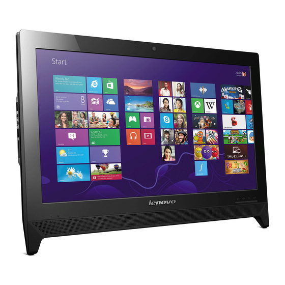
Lenovo C260 All-In-One PC Hardware
Maintenance Manual
aideaideaCentreidea
Machine Types: 10160/F0AK [C260]
Related Manuals for Lenovo C260
Summary of Contents for Lenovo C260
-
Page 1
Lenovo C260 All-In-One PC Hardware Maintenance Manual aideaideaCentreidea Machine Types: 10160/F0AK [C260]… -
Page 3
Lenovo C260 All-In-One PC Hardware Maintenance Manual Machine Types: 10160/F0AK [C260]… -
Page 4
First Edition (February 2014)25th © Copyright Lenovo 2013, 2014. LIMITED AND RESTRICTED RIGHTS NOTICE: If data or software are delivered pursuant a General Services Administration “GSA” contract, use, reproduction, or disclosure is subject to restrictions set forth in Contract No. -
Page 5: Table Of Contents
Changing booting mode … Replacing the LED panel… Exiting the Lenovo BIOS Setup Utility program . . Chapter 8. Additional Service Information .
-
Page 6
Lenovo C260 All-In-One PC Hardware Maintenance Manual… -
Page 7: Chapter 1. About This Manual
Chapter 1. About this manual This manual contains service and reference information for Lenovo C260 All-In-One computer listed on the cover. It is intended only for trained servicers who are familiar with Lenovo computer products. Before servicing a Lenovo product, be sure to read the Safety Information.
-
Page 8
Lenovo C260 All-In-One PC Hardware Maintenance Manual… -
Page 9: Chapter 2. Safety Information
Electrical current from power, telephone, and communication cables can be hazardous. To avoid personal injury or equipment damage, disconnect any attached power cords, telecommunication cables, network cables, and modem cables before you open the computer covers, unless instructed otherwise in the installation and configuration procedures. © Copyright Lenovo 2013, 2014…
-
Page 10
– Blowers and fans – Motor generators and similar units. (This practice ensures correct grounding of the units.) • If an electrical accident occurs: – Use caution; do not become a victim yourself. Lenovo C260 All-In-One PC Hardware Maintenance Manual… -
Page 11: Safety Inspection Guide
– Switch off power. – Send another person to get medical aid. Safety inspection guide The intent of this inspection guide is to assist you in identifying potential hazards posed by these products. Each computer, as it was designed and built, had required safety items installed to protect users and service personnel from injury.
-
Page 12: Grounding Requirements
• Connect and disconnect cables as described in the following table when installing, moving, or opening covers on this product or attached devices. Lenovo C260 All-In-One PC Hardware Maintenance Manual…
-
Page 13
To Connect To Disconnect 1. Turn everything OFF. 1. Turn everything OFF. 2. First, attach all cables to devices. 2. First, remove power cords from outlets. 3. Attach signal cables to connectors. 3. Remove signal cables from connectors. 4. Attach power cords to outlet. 4. -
Page 14
To remove all electrical current from the device, ensure that all power cords are disconnected from the power source. CAUTION: Do not place any object weighing more than 82 kg (180 lbs.) on top of rack-mounted devices. Lenovo C260 All-In-One PC Hardware Maintenance Manual… -
Page 15: Chapter 3. General Information
This section lists the physical specifications. Environment Air temperature: Operating: 10° to 35°C Transit: -20° to 55°C Humidity: Operating: 35% to 80% Transit: 20% to 90% (40°C) Altitude: 86KPa to 106KPa Electrical input: Input voltage: 90V-264V(AC) Input frequency: 47Hz-63Hz © Copyright Lenovo 2013, 2014…
-
Page 16
Lenovo C260 All-In-One PC Hardware Maintenance Manual… -
Page 17: Chapter 4. General Checkout
• If the computer displays a POST error, go to “POST error codes”. • If the computer hangs and no error is displayed, continue at step 7. 7. If the test stops and you cannot continue, replace the last device tested. © Copyright Lenovo 2013, 2014…
-
Page 18
Lenovo C260 All-In-One PC Hardware Maintenance Manual… -
Page 19: Chapter 5. Using The Setup Utility
1. If your computer is already on when you start this procedure, shut down the operating system and turn off the computer. 2. Press and hold the F1 key then turn on the computer. When the Lenovo BIOS Setup Utility program is displayed, release the F1 key.
-
Page 20
Administrator Password if you are responsible for maintaining the settings of several computers. After you set an Administrator Password, a password prompt is displayed every time you access the Lenovo BIOS Setup Utility program. If both the Administrator and Power-On Password are set, you can type either password. However, you must use your Administrator Password to change any configuration settings. -
Page 21: Enabling Or Disabling A Device
Power-On Password When a Power-On Password is set, you cannot start the Lenovo BIOS Setup Utility program until a valid password is typed from the keyboard. Setting, changing, or deleting a Power-On Password Note: A password can be any combination of letters and numbers up to 16 characters (a-z and 0-9).
-
Page 22: Selecting A Startup Device
Select Network Setup, press the Enter key, then select Onboard Ethernet Support or LAN Boot Agent. 4. Select Disabled or Enabled and press the Enter key. 5. Return to the Lenovo BIOS Setup Utility program menu and select the Exit option. 6. Select Save Changes and Exit from the menu. Notes: a.
-
Page 23: Changing Booting Mode
Exiting the Lenovo BIOS Setup Utility program After you finish viewing or changing settings, press the Esc key to return to the Lenovo BIOS Setup Utility program main menu. You might have to press the Esc key several times. Do one of the following: •…
-
Page 24
Lenovo C260 All-In-One PC Hardware Maintenance Manual… -
Page 25: Chapter 6. Symptom-To-Fru Index
Check that the following are properly installed: Reseat connectors • Power Cord • On/Off Switch connector • System Board Power Supply connectors • Microprocessor connections Check the power cord. Power Cord Check the power-on switch. Power-on Switch © Copyright Lenovo 2013, 2014…
-
Page 26: Post Error Codes
3. Power-on the computer to re-test the system. 4. Repeat steps 1 through 3 until you find the failing device or component. If all devices and components have been removed and the problem continues, replace the system board. Lenovo C260 All-In-One PC Hardware Maintenance Manual…
-
Page 27: Chapter 7. Replacing Hardware
Attention: Do not remove the computer cover or attempt any repair before reading the “Important safety information” in the Safety and Warranty Guide that was included with your computer. To obtain copies of the Safety and Warranty Guide, go to the Support Web site at: http://support.lenovo.com. Note: Use only parts provided by Lenovo.
-
Page 28: Replacing The Keyboard And Mouse
Remove any media (disks, CDs, DVDs, or memory cards) from the drives, shut down the operating system, and turn off the computer and all attached devices. Step 2. Locate the connector for the power cord. Refer to “Rear view”. Lenovo C260 All-In-One PC Hardware Maintenance Manual…
-
Page 29
Step 3. Disconnect the failing power adapter from the computer. Step 4. To install the new power adapter: Connect the new power adapter to the same connector. Chapter 7 Replacing hardware… -
Page 30: Replacing The Computer Stand
Refer to “Left and right view” and “Rear view” for help with locating the various connectors. Step 4. Use a flat head screw driver to remove the stand cover as shown. Lenovo C260 All-In-One PC Hardware Maintenance Manual…
-
Page 31: Removing The Rear Cover
Step 5. Remove the 2 screws that secure the computer stand to the rear cover. Step 6. Slide out the computer stand as shown. Step 7. To install the new computer stand: Line up the computer stand with the mounting hole on the rear cover and slide it into position. Secure the new computer stand to the rear cover with the 2 screws.
-
Page 32: To Remove Rear Cover
Note: It may be helpful to place the computer face-down on a soft flat surface for this procedure. Lenovo recommends that you use a blanket, towel, or other soft cloth to protect the touch screen from scratches or other damage.
-
Page 33
Step 5. Lift up the rubbers that protect the 2 screws, remove the 2 screws that secure the rear cover to the front bezel. Step 6. The rear cover and front bezel are pinned together, use a plastic flat-head screwdriver, insert to the gap in-between the rear cover and the front bezel, slide the screwdriver along the bottom edge to loose it, then lift up the rear cover as shown. -
Page 34: Replacing The Optical Drive
Refer to “Left and right view” and “Rear view” for help with locating the various connectors. Step 4. Remove the rear cover, refer to “Removing the rear cover”. Lenovo C260 All-In-One PC Hardware Maintenance Manual…
-
Page 35
Step 5. Slide out the optical drive as shown. Step 6. Use a small flat head screwdriver to press and push out the pins that secure the cover to the disk. Step 7. Separate the cover from the defective optical drive. Step 8. -
Page 36: Replacing A Memory Module
Remove any media (disks, CDs, DVDs or memory cards) from the drives, shut down the operating system, and turn off the computer and all attached devices. Step 2. Unplug all power cords from electrical outlets. Lenovo C260 All-In-One PC Hardware Maintenance Manual…
-
Page 37
Step 3. Disconnect all cables attached to the computer. This includes power cords, input/output (I/O) cables, and any other cables that are connected to the computer. Refer to “Left and right view” and “Rear view” for help with locating the various connectors. Step 4. -
Page 38: Replacing The Wi-Fi Card
Reattach the rear cover, stand and stand cover. Replacing the speaker system Note: Turn off the computer and wait 3 to 5 minutes to let it cool down before removing the rear cover. To replace the speaker system: Lenovo C260 All-In-One PC Hardware Maintenance Manual…
-
Page 39: Replacing The Indicator Board
Reattach the rear cover, stand and stand cover. Replacing the indicator board [A60110] Error in document «D:All ProsC260HMMLenovo C260 Hardware Maintainence Manual.ditamap» on reference (topicref) element at line 81: Unable to open document «D:All ProsC260HMMReplacing the indicator board.dita» Replacing the power switch board Note: Turn off the computer and wait 3 to 5 minutes to let it cool down before removing the rear cover.
-
Page 40: Replacing The System Fan
Refer to “Left and right view” and “Rear view” for help with locating the various connectors. Step 4. Remove the rear cover. Refer to «Removing the rear cover». Lenovo C260 All-In-One PC Hardware Maintenance Manual…
-
Page 41: Replacing The Motherboard
Step 5. Disconnect the power cable from the connector on the motherboard. Step 6. Remove the 2 screws that secure the system fan to the rear cover. Step 7. Lift up the system fan to remove it. Step 8. To install the new system fan: Line up the new system fan with the mounting holes on the rear cover and place it into position.
-
Page 42
Insert the notched end of the Wi-Fi card into the card port on the new motherboard and secure it with the screw. Connect the antenna cable(s) to the Wi-Fi card. Connect all the cables to the new motherboard. Step 12. Reattach the rear cover, stand and stand cover. Lenovo C260 All-In-One PC Hardware Maintenance Manual… -
Page 43: Replacing The Heat-Sink
Replacing the heat-sink Note: Turn off the computer and wait 3 to 5 minutes to let it cool down before removing the rear cover. To replace the heat-sink: Step 1. Remove any media (disks, CDs, DVDs or memory cards) from the drives, shut down the operating system, and turn off the computer and all attached devices.
-
Page 44: Replacing The Camera
Refer to “Left and right view” and “Rear view” for help with locating the various connectors. Step 4. Remove the rear cover. Refer to “Removing the rear cover”. Lenovo C260 All-In-One PC Hardware Maintenance Manual…
-
Page 45: Replacing The Converter Board
Step 5. Remove the 2 screws that secure the camera to the front bezel. Step 6. Gently slide out the camera and disconnect the cable from the camera. Step 7. To install the new camera: Connect the data cable to the new camera. Line up the holes in the new camera with the mounting holes on the front bezel and secure the new camera with the 2 screws.
-
Page 46
Disconnect the 2 cables from the converter board. Step 6. Remove the screw that secures the converter board to the bracket. Step 7. Lift up the converter board to remove it. Step 8. To install the new converter board: Lenovo C260 All-In-One PC Hardware Maintenance Manual… -
Page 47: Replacing The Led Panel
Line up the holes in the new converter board with the mounting holes on the bracket and secure the new converter board with the screw. Connect the 2 cables to the new converter board. Step 9. Reattach the rear cover and secure it with the screws. Replacing the LED panel Note: Turn off the computer and wait 3 to 5 minutes to let it cool down before removing the rear cover.
-
Page 48
Step 7. Disconnect the LVDS and converter cables from the connector on the LED panel. Lenovo C260 All-In-One PC Hardware Maintenance Manual… -
Page 49
Step 8. Remove the 7 screws that secure the LED panel to the front bezel. The LED panel is glued to the front bezel, gently remove the LED panel from the front bezel. Step 9. Remove the 4 screws that secure the LED panel to the bracket to separate the LED panel from the bracket. -
Page 50
Step 11. Reattach the converter board, camera, rear cover, stand and stand cover. Lenovo C260 All-In-One PC Hardware Maintenance Manual… -
Page 51: Chapter 8. Additional Service Information
• Wake Up on Alarm: You can specify a date and time at which the computer will be turned on automatically. This can be either a single event , a daily event or a weekly event. • Wake Up on LAN: This feature allows LAN adapter card to wake the System. © Copyright Lenovo 2013, 2014…