-
#1
-
1,8 MB
Просмотры: 7.610
-
#2
-
84,5 KB
Просмотры: 978
-
#3
mservis написал(а):
ftp://chadt.us
username: snowmobile@chadt.us
password: manual
заходить через оперу или тотал командер, эксплоер не пойдет.
Кстати, там и на ямахи, кошки и скидушки есть много.
-
#4
-
22,9 MB
Просмотры: 5.369 -
22,9 MB
Просмотры: 2.956 -
22,9 MB
Просмотры: 2.637 -
8 MB
Просмотры: 2.606 -

210,7 KB
Просмотры: 18.140
-
#5
Может кому пригодится выкладываю сервис мануал IQ 2007-2008  :)")
-
13,3 MB
Просмотры: 3.888
-
#6
некоторая информация по двигателям MPE 750 FS/FST
-
1.010,8 KB
Просмотры: 1.003 -
1,6 MB
Просмотры: 875
-
#7
polaris transport 550 юзерский
-
2,5 MB
Просмотры: 1.327
-
#8
POLARIS SWITCHBACK 2012 модельный. Инструкция пользователя
-
3,4 MB
Просмотры: 1.226

ГАД
Активный участник
-
#9
2010-2012 PRO-RIDE RUSH/Switchback/RMK Service Manual
-
18 MB
Просмотры: 2.059
-
#10
может кому пригодится
-
4,5 MB
Просмотры: 2.969
-
#11
Service manual 2007-2008.
-
13,3 MB
Просмотры: 1.970
-
#12
Polaris 2006-2007 FS/FST service manual
Имеется полное описание 4-х тактного двигателя 750куб. см, в том числе с турбиной.
-
20,9 MB
Просмотры: 1.590
-
#13
WarMan написал(а):
Где взять мануал на polaris EDGE touring 550 выпуск 2004г заранее благодарен
Тут с 2007 г. Может он не сильно отличается?
-
7,3 MB
Просмотры: 1.331
-
#14
Доброго времени суток. Не могу найти литературу на Polaris switchback 800. 2004 юбилейный. Ткните, может плохо ищу.
-
#15
Есть у кого мануал на IQ 750 2008г
-
#17
У кого есть нормальная книжка на поларис вт лх 500 с моментами затяжек гаек, болтов, размерами итд, поделитесь
- Manuals
- Brands
- Polaris Manuals
- Snowmobiles
ManualsLib has more than 228 Polaris Snowmobiles manuals
Click on an alphabet below to see the full list of models starting with that letter:
1
2
3
5
6
7
8
D
F
I
M
P
R
S
T
W
Popular manuals
393 pages
INDY TRAIL RMK Service Manual
747 pages
850 PRO-RMK 155 2020 Manual
327 pages
2007 Two Stroke Service Manual
727 pages
850 MATRYX INDY XC 129 2021 Manual
179 pages
FST IQ Cruiser Owner’s Manual

139 pages
550 Transport Owner’s Manual
137 pages
Dragon Owner’s Manual

243 pages
MATRIX INDY VR1 Series Owner’s Manual

92 pages
120 XC SP Owner’s Manual
142 pages
600 RMK Owner’s Manual

127 pages
600 RMK Owner’s Manual

165 pages
FST IQ Touring Owner’s Manual
140 pages
2015 600 RMK Owner’s Manual

159 pages
600 EDGE Touring Owner’s Manual

141 pages
600 Dragon SP Owner’s Manual
132 pages
600 Indy Owner’s Manual

165 pages
FS IQ Touring Owner’s Manual

99 pages
2000 120 XCR Service Manual

57 pages
Playmate 1971 Shop Manual

133 pages
600 RMK Shift Owner’s Manual
Models
Document Type
1
120 XC SP

Owner’s Manual • Rider’s Safety Manual And Owner’s Operation And Maintenance Manual • Universal Owner’s Safety And Maintenance Manual
120 XC SP 2003
Owner’s Manual
2
2000 120 XCR
Service Manual
2001 120 XC SP
Service Manual
2002 120 XC SP
Service Manual
2003 120 XC SP
Service Manual
2004 120 PRO X
Service Manual
2005 120 PRO X
Service Manual
2006 120 PRO X
Service Manual
2007 120 Dragon
Service Manual
2007 340 Touring
Service Manual
2007 500 XC SP
Service Manual
2007 Dragon
Service Manual • Owner’s Manual
2007 Dragon RMK
Service Manual
2007 HO IQ LX Cleanfire
Service Manual
2007 HO IQ:
2007 HO IQ Cleanfire
Service Manual
2007 HO RMK 144 F/O
Service Manual
2007 HO RMK 155 F/O
Service Manual
2007 Super Sport
Service Manual
2007 Trail RMK
Service Manual
2007 Trail Touring Deluxe
Service Manual
2007 Two Stroke
Service Manual
2007 Widetrack LX
Service Manual
2014 600 Indy
Owner’s Manual
2014 800 Indy
Owner’s Manual
2015 600 RMK
Owner’s Manual
2015 800 PRO RMK
Owner’s Manual
2015 800 RMK ASSAULT
Owner’s Manual
2015600 PRO RMK
Owner’s Manual
2015800 RMK
Owner’s Manual
2882859
Quick Manual
2882915
Quick Manual
3
340 LX 2007
Owner’s Manual • Service Manual • Service Manual
5
550 LX 2007
Owner’s Manual • Service Manual • Service Manual
550 Transport
Owner’s Manual • Owner’s Manual
550 Transport 2009
Owner’s Manual • Service Manual
6
600 Dragon SP
Owner’s Manual • Owner’s Manual • Owner’s Manual • Service Manual • Service Manual
600 Dragon SP 2009
Owner’s Manual
600 Dragon Switchback 2009
Owner’s Manual
600 EDGE RMK
Service Manual
600 EDGE Touring 121
Owner’s Manual • Owner’s Manual
600 EDGE Touring 2006
Owner’s Manual • Manual
600 HO RMK 155
Owner’s Manual • Owner’s Manual • Owner’s Manual
600 INDY Voyager 2014
Owner’s Manual • Owner’s Manual • Owner’s Manual
600 IQ 2009
Owner’s Manual
600 IQ Touring 2009
Owner’s Manual
600 PRO RMK
Owner’s Manual • Owner’s Manual
600 PRO RMK 2014
Owner’s Manual
600 RMK
Owner’s Manual • Owner’s Manual • Owner’s Manual • Owner’s Manual
600 RMK 144
Owner’s Manual • Owner’s Manual • Owner’s Manual
600 RMK 2006
Owner’s Manual
600 RMK 2014
Owner’s Manual
600 RMK Shift 2009
Owner’s Manual
600 Rush 2017
Owner’s Manual For Maintenance And Safety
600 SwitchBack 2006
Owner’s Manual
600 Switchback 2009
Owner’s Manual
600 Switchback 2017
Owner’s Manual For Maintenance And Safety
650 2023
Owner’s Manual
650 MATRYX INDY VR1 129 2021
Manual
650 MATRYX INDY VR1 137 2021
Manual
650 MATRYX INDY XC 137 2021
Manual
650 MATRYX SWITCHBACK ASSAULT 146 2021
Manual
650 Pro RMK 155 2023
Owner’s Manual
650 RMK Khaos 146 Slash 2023
Owner’s Manual
7
700 EDGE RMK
Service Manual
700 RMK 155
Owner’s Manual
700 RMK 155 2009
Owner’s Manual
8
800 Assault RMK 2009
Owner’s Manual
800 Dragon RMK 2009
Owner’s Manual
800 Dragon SP
Owner’s Manual
800 Dragon SP 2009
Owner’s Manual
800 Dragon Swtchback 2009
Owner’s Manual
800 EDGE RMK
Service Manual
800 Indy
Owner’s Manual • Owner’s Manual
800 IQ 2009
Owner’s Manual
800 PRO RMK
Owner’s Manual • Owner’s Manual • Owner’s Manual
800 PRO RMK 2014
Owner’s Manual
800 RMK
Owner’s Manual • Owner’s Manual • Owner’s Manual
800 RMK 155
Owner’s Manual
800 RMK 155 2009
Owner’s Manual
800 RMK 2014
Owner’s Manual
800 RMK ASSAULT
Owner’s Manual • Owner’s Manual • Owner’s Manual
800 RMK ASSAULT 2014
Owner’s Manual
800 RMK Shift 2009
Owner’s Manual
800 Rush 2017
Owner’s Manual For Maintenance And Safety
800 Switchback 2009
Owner’s Manual
800 Switchback 2017
Owner’s Manual For Maintenance And Safety
800 XC SP EDGE M-10
Owner’s Manual Supplement
800 XC SP EDGE M-10 F/O 2004
Owner’s Manual Supplement
850 2023
Owner’s Manual
850 MATRYX INDY VR1 129 2021
Manual
850 MATRYX INDY VR1 137 2021
Manual
850 MATRYX INDY XC 129 2021
Manual
850 MATRYX INDY XC 137 2021
Manual
850 MATRYX SWITCHBACK ASSAULT 146 2021
Manual
850 Pro RMK 155 2023
Owner’s Manual
850 PRO-RMK 155 2.6″ QD 2021
Manual
850 PRO-RMK 155 2020
Manual
850 PRO-RMK 155 3.0 Track 2020
Manual
850 PRO-RMK 155 3.0″ CC 2021 850 RMK Khaos 155 2.6″ QD 2021
Manual
850 PRO-RMK 155 3.0″ QD 2021
Manual
850 PRO-RMK 163 2.6″ QD 2021
Manual
850 PRO-RMK 163 2020
Manual
850 PRO-RMK 163 3.0 Track 2020
Manual
850 PRO-RMK 163 3.0″ CC 2021
Manual
850 PRO-RMK 163 3.0″ QD 2021
Manual
850 PRO-RMK 165 2.75″ QD 2021
Manual
850 PRO-RMK 174 3.0 Track 2020
Manual
850 PRO-RMK 174 3.0″ QD 2021
Manual
850 RMK Khaos 146 Slash 2023
Owner’s Manual
850 RMK Khaos 155 2020
Manual
850 RMK Khaos 155 2023
Owner’s Manual
850 RMK Khaos 155 Slash 2023
Owner’s Manual
850 RMK Khaos 163 Slash 2023
Owner’s Manual
850 RMK Khaos 165 Slash 2023
Owner’s Manual
850 SKS 155 2020
Manual
850 SKS 155 2021
Manual
D
Dragon
Owner’s Manual
F
FS IQ Touring
Owner’s Manual
FS IQ Touring 2007
Owner’s Manual
FS IQ TOURING 2008
Owner’s Manual
FS IQ Touring 2009
Owner’s Manual
FS IQ TOURING 7427 C
Owner’s Manual
FST IQ 2007
Owner’s Manual • Service Manual
FST IQ Cruiser
Owner’s Manual
FST IQ Cruiser 2007
Owner’s Manual
FST IQ LX
Owner’s Manual
FST IQ LX 2007
Owner’s Manual
FST IQ Touring
Owner’s Manual
FST IQ Touring 2007
Owner’s Manual
FST IQ Touring 2008
Owner’s Manual
FST IQ Touring 2009
Owner’s Manual
FST IQ Touring 2010
Owner’s Manual
FST SwitchBack
Owner’s Manual
FST SwitchBack 2007
Owner’s Manual
I
Indy 340 Touring
Owner’s Manual • Manual
Indy 340 Touring 2006
Owner’s Manual
INDY 500 RMK
Service Manual
INDY 500 SKS EURO
Service Manual
INDY 700 EURO SKS
Service Manual
INDY 700 SKS
Service Manual
INDY TRAIL RMK
Service Manual
IQ Cruiser 2008
Owner’s Manual
IQ Shift 136
Owner’s Manual
IQ Shift 136 2009
Owner’s Manual
M
MATRIX 650 INDY VR1 129
Owner’s Manual
MATRIX 650 INDY VR1 137
Owner’s Manual
MATRIX 650 INDY XC Launch Edition 129
Owner’s Manual
MATRIX 650 SWITCHBACK ASSAULT 146
Owner’s Manual
MATRIX 850 INDY XC Launch Edition 129
Owner’s Manual
MATRIX 850 SWITCHBACK ASSAULT 146
Owner’s Manual
MATRIX INDY VR1 Series
Owner’s Manual
MATRIX INDY XC Series
Owner’s Manual
MATRIX SWITCHBACK ASSAULT Series
Owner’s Manual
MATRYX 2023
Owner’s Manual
MATRYX SLASH 2023
Owner’s Manual
P
PATRIOT 9R 2023
Owner’s Manual
Patriot 9R Pro RMK 155 Slash 2023
Owner’s Manual
Patriot 9R RMK Khaos 146 Slash 2023
Owner’s Manual
PATRIOT BOOST 2023
Owner’s Manual
Patriot Boost Pro RMK 155 Slash 2023
Owner’s Manual
Patriot Boost Pro RMK 163 Slash 2023
Owner’s Manual
Patriot Boost Pro RMK 165 Slash 2023
Owner’s Manual
Patriot Boost RMK Khaos 155 Slash 2023
Owner’s Manual
Patriot Boost RMK Khaos 163 Slash 2023
Owner’s Manual
Patriot Boost RMK Khaos 165 Slash 2023
Owner’s Manual
Playmate 1971
Shop Manual
PRO RMK 2023
Owner’s Manual
R
RMK KHAOS 2023
Owner’s Manual
S
S20EFK8RE
Manual
S20EFK8RS
Manual
S20EFM8RS
Manual
S20EFN8RE
Manual
S20EFN8RS
Manual
S20EFS8RE
Manual
S20EFS8RS
Manual
S20EFT8RE
Manual
S20EFT8RS
Manual
S20EGK8RS
Manual
S20EGM8RE
Manual
S20EGM8RS
Manual
S20EHM8RS
Manual
S21EF58RL
Manual
S21EFK8RB
Manual
S21EFK8RC
Manual
S21EFK8RH
Manual
S21EFK8RS
Manual
S21EFM8RC
Manual
S21EFN8RC
Manual
S21EFS8RE
Manual
S21EFS8RS
Manual
S21EFT8RB
Manual
S21EFT8RC
Manual
S21EFT8RH
Manual
S21EFT8RL
Manual
S21EFT8RS
Manual
S21EGK8RB
Manual
S21EGK8RC
Manual
S21EGK8RH
Manual
S21EGK8RS
Manual
S21EGM8RC
Manual
S21EGT8RB
Manual
S21EGT8RC
Manual
S21EGT8RH
Manual
S21EGT8RL
Manual
S21EGT8RS
Manual
S21EHK8RC
Manual
S21TDP6RE
Manual
S21TDP6RS
Manual
S21TDP8RE
Manual
S21TDP8RS
Manual
S21TDV6RS
Manual
S21TDV8RS
Manual
S21TKP6RE
Manual
S21TKP6RS
Manual
S21TKP8RE
Manual
S21TKP8RS
Manual
S21TKV6RE
Manual
S21TKV6RS
Manual
S21TKV8RE
Manual
S21TKV8RS
Manual
S21TLC6RE
Manual
S21TLC6RS
Manual
S21TLC8RE
Manual
S21TLC8RS
Manual
T
Trail Touring 2006
Owner’s Manual • Manual
Trail Touring 2009
Owner’s Manual • Service Manual
W
WideTrak 2006
Owner’s Manual

Руководство на английском языке по эксплуатации и техническому обслуживанию снегоходов Polaris 2001 года выпуска.
- Год издания: —
- Страниц: 169
- Формат: PDF
- Размер: 8,9 Mb

Сборник руководств на английском языке по эксплуатации и техническому обслуживанию снегоходов Polaris 120/PRO R/Xer/XC SP 2003-2013 годов выпуска.
- Год издания: —
- Страниц: —
- Формат: PDF
- Размер: 22,7 Mb

Сборник руководств на английском языке по эксплуатации и техническому обслуживанию снегоходов Polaris 340 Edge/LX/Touring 2007-2008 годов выпуска.
- Год издания: —
- Страниц: 153/148/137
- Формат: PDF
- Размер: 8,4 Mb

Руководство на английском языке по эксплуатации и техническому обслуживанию снегохода Polaris 440 IQ 2007 года выпуска.
- Год издания: 2007
- Страниц: 118
- Формат: PDF
- Размер: 5,9 Mb

Руководство на английском языке по эксплуатации и техническому обслуживанию снегохода Polaris 500 XC SP 2007 года выпуска.
- Год издания: —
- Страниц: 148
- Формат: PDF
- Размер: 3,0 Mb

Сборник руководств на английском языке по эксплуатации и техническому обслуживанию снегоходов Polaris 550 IQ Shift/LX/Transport 2007-2010 годов выпуска.
- Год издания: —
- Страниц: 121/137/139/148
- Формат: PDF
- Размер: 12,6 Mb

Сборник руководств на английском языке по эксплуатации и техническому обслуживанию снегоходов Polaris 600 2007-2010 годов выпуска.
- Год издания: —
- Страниц: —
- Формат: PDF
- Размер: 105,8 Mb

Сборник руководств на английском языке по эксплуатации и техническому обслуживанию снегоходов Polaris 700 Classic/Fusion/IQ/RMK/Switchback/Touring 2006-2008 годов выпуска.
- Год издания: —
- Страниц: 133/137/139/154
- Формат: PDF
- Размер: 36,6 Mb
Сборник руководств на английском языке по эксплуатации и техническому обслуживанию снегоходов Polaris 800 Dragon IQ/Dragon SP/Dragon Switchback/IQ/PRO RMK/RMK/RMK Assault/Rush/Switchback 2009-2013 годов выпуска.
- Год издания: —
- Страниц: 135/137/141
- Формат: PDF
- Размер: 19,5 Mb

Сборник руководств на английском языке по эксплуатации и техническому обслуживанию снегоходов Polaris 900 Fusion/RMK/Switchback 2006 года выпуска.
- Год издания: —
- Страниц: 137/139
- Формат: PDF
- Размер: 21,6 Mb

Руководство на английском языке по эксплуатации и техническому обслуживанию снегохода Polaris Dragon RMK 2006 года выпуска.
- Год издания: —
- Страниц: 135
- Формат: PDF
- Размер: 7,8 Mb

Сборник руководств на английском языке по эксплуатации и техническому обслуживанию снегоходов Polaris Edge 2005-2006 годов выпуска.
- Год издания: —
- Страниц: 153/157
- Формат: PDF
- Размер: 11,5 Mb

Руководство на английском языке по эксплуатации и техническому обслуживанию снегохода Polaris Frontier 2002 года выпуска.
- Год издания: —
- Страниц: 130
- Формат: PDF
- Размер: 2,0 Mb

Сборник руководств на английском языке по эксплуатации и техническому обслуживанию снегоходов Polaris FS Classic/IQ Touring/Touring 2006-2009 годов выпуска.
- Год издания: —
- Страниц: 176/179/165/157
- Формат: PDF
- Размер: 42,7 Mb

Сборник руководств на английском языке по эксплуатации и техническому обслуживанию снегоходов Polaris FST Classic/IQ/IQ Cruiser/IQ LX/IQ Touring/Switchback/Touring 2006-2010 годов выпуска.
- Год издания: —
- Страниц: —
- Формат: PDF
- Размер: 50,7 Mb

Руководство на английском языке по эксплуатации и техническому обслуживанию снегохода Polaris Indy 340 Touring 2006 года выпуска.
- Год издания: —
- Страниц: 159
- Формат: PDF
- Размер: 7,0 Mb

Сборник руководств на английском языке по эксплуатации и техническому обслуживанию снегоходов Polaris IQ Cruiser/Shift/Shift 136/Turbo/Turbo Dragon/Turbo LX/Turbo Switchback 2008-2010 годов выпуска.
- Год издания: —
- Страниц: —
- Формат: PDF
- Размер: 41,4 Mb

Руководство на английском языке по эксплуатации и техническому обслуживанию снегохода Polaris PRO X 2004 года выпуска.
- Год издания: —
- Страниц: 129
- Формат: PDF
- Размер: 11,1 Mb

Руководство на английском языке по эксплуатации и техническому обслуживанию снегохода Polaris RMK 2004 года выпуска.
- Год издания: —
- Страниц: 127
- Формат: PDF
- Размер: 10,1 Mb

Руководство на английском языке по эксплуатации и техническому обслуживанию снегохода Polaris Rush 2010 года выпуска.
- Год издания: —
- Страниц: 134
- Формат: PDF
- Размер: 8,9 Mb
Сборник руководств на английском языке по эксплуатации и техническому обслуживанию снегоходов Polaris Supersport 2007-2008 годов выпуска.
- Год издания: —
- Страниц: 137/148
- Формат: PDF
- Размер: 5,8 Mb

Руководство на английском языке по эксплуатации и техническому обслуживанию снегохода Polaris Trial RMK 2010 года выпуска.
- Год издания: —
- Страниц: 133
- Формат: PDF
- Размер: 2,4 Mb

Сборник руководств на английском языке по эксплуатации и техническому обслуживанию снегоходов Polaris Trail Touring/DLX 2006-2010 годов выпуска.
- Год издания: —
- Страниц: 137/139/153/159
- Формат: PDF
- Размер: 13,5 Mb

Руководство на английском языке по эксплуатации и техническому обслуживанию снегохода Polaris Turbo LX 2010 года выпуска.
- Год издания: —
- Страниц: 159
- Формат: PDF
- Размер: 6,1 Mb

Руководство на английском языке по эксплуатации и техническому обслуживанию снегохода Polaris TX Starfire 1973 года выпуска.
- Год издания: —
- Страниц: 92
- Формат: PDF
- Размер: 8,3 Mb

Сборник руководств на английском языке по эксплуатации и техническому обслуживанию снегоходов Polaris WideTrak/LX 2006-2010 годов выпуска.
- Год издания: —
- Страниц: 127/129/153/159
- Формат: PDF
- Размер: 16,5 Mb

|
Title |
File Size |
Download Links |
|
1971 Polaris Playmate Shop Manual.pdf |
3.4Mb |
Download |
|
1973 Polaris TX Starfire Owner`s Manual.pdf |
8.3Mb |
Download |
|
2001 Polaris Owner`s Safety and Maintenance Manual.pdf |
8.9Mb |
Download |
|
2002 Polaris 120 XC SP Owner’s Safety And Maintenance Manual.pdf |
4Mb |
Download |
|
2002 Polaris Frontier Owner`s Manual.pdf |
2Mb |
Download |
|
2003-2013 Polaris 120/PRO R/Xer/XC SP Service Owner’s Manual.rar |
22.7Mb |
Download |
|
2004 Polaris PRO X Owner`s Manual.pdf |
11.1Mb |
Download |
|
2004 Polaris RMK Owner`s Manual.pdf |
10.1Mb |
Download |
|
2005-2006 Polaris Edge Owner`s Manual.rar |
11.5Mb |
Download |
|
2006 Polaris 900 Fusion/RMK/Switchback Owner`s Manual.rar |
21.6Mb |
Download |
|
2006 Polaris Dragon RMK Owner`s Manual.pdf |
7.8Mb |
Download |
|
2006 Polaris Indy 340 Touring Owner`s Manual.pdf |
7Mb |
Download |
|
2006-2008 Polaris 700 Classic/Fusion/IQ/RMK/Switchback/Touring Owner`s Manual.rar |
36.6Mb |
Download |
|
2006-2009 Polaris FS Classic/IQ Touring/Touring Owner`s Manual.rar |
42.7Mb |
Download |
|
2006-2010 Polaris FST Classic/IQ/IQ Cruiser/IQ LX/IQ Touring/Switchback/Touring Owner`s Manual.rar |
50.7Mb |
Download |
|
2006-2010 Polaris Trail Touring/DLX Owner`s Manual.rar |
13.5Mb |
Download |
|
2006-2010 Polaris WideTrak/LX Owner`s Manual.rar |
16.5Mb |
Download |
|
2007 Polaris 340 LX, 340 TOURING, WIDETRACK LX, 500 XC SP, SUPER SPORT, 550 LX, TRAIL RMK, TRAIL TOURING DELUXE Service Manual.pdf |
23.1Mb |
Download |
|
2007 Polaris 440 IQ Service Owner’s Manual.pdf |
5.9Mb |
Download |
|
2007 Polaris 500 XC SP Owner`s Manual.pdf |
3Mb |
Download |
|
2007 Polaris DRAGON RMK, HO RMK 144 F/O, HO RMK 155 F/O Service Manual.pdf |
23.1Mb |
Download |
|
2007 Polaris HO IQ LX CLEANFIRE, HO SWITCHBACK, HO SWITCHBACK CLEANFIRE, HO IQ TOURING CLEANFIRE Service Manual.pdf |
23.1Mb |
Download |
|
2007 Polaris Two Stroke Service Manual.pdf |
23.1Mb |
Download |
|
2007-2008 Polaris 340 Edge/LX/Touring Service Owner’s Manual.rar |
8.4Mb |
Download |
|
2007-2008 Polaris Supersport Owner`s Manual.rar |
5.8Mb |
Download |
|
2007-2010 Polaris 550 IQ Shift/LX/Transport Owner`s Manual.rar |
12.6Mb |
Download |
|
2007-2010 Polaris 600 Owner`s Manual.rar |
105.8Mb |
Download |
|
2008-2010 Polaris IQ Cruiser/Shift/Shift 136/Turbo/Turbo Dragon/Turbo LX/Turbo Switchback Owner`s Manual.rar |
41.4Mb |
Download |
|
2009-2013 Polaris 800 Dragon IQ/Dragon SP/Dragon Switchback/IQ/PRO RMK/RMK/RMK Assault/Rush/Switchback Owner`s Manual.rar |
19.5Mb |
Download |
|
2010 Polaris Rush Owner`s Manual.pdf |
8.9Mb |
Download |
|
2010 Polaris Trial RMK Owner`s Manual.pdf |
2.4Mb |
Download |
|
2010 Polaris Turbo LX Owner`s Manual.pdf |
6.1Mb |
Download |
|
2017 Polaris 600 Rush Owner’s Manual For Maintenance And Safety.pdf |
2.7Mb |
Download |
|
Polaris INDY TRAIL RMK, INDY 500 RMK, INDY 700 SKS, INDY 700 EURO SKS, 700 EDGE RMK, 800 EDGE RMK, INDY 500 SKS EURO, 600 EDGE RMK Service Manual.pdf |
6.7Mb |
Download |
Snowmobile «Polaris» — one of the best caterpillar all-terrain vehicles of our time — was created in 1954 by the brothers Edgar and Allan Hittons. The first device was generally
successful, although the creators expected more. Nevertheless, the Motosleds were bought for a decent amount by the Hitton neighbor, and this was the impetus for the construction of the next
instance. The money ($ 465) from the sale, the brothers invested in a new, improved machine.
If the brothers equipped their first snowmobile with a lawnmower engine, low-power and unreliable, then for the next car they purchased a two-cylinder motorcycle engine that develops traction of
12 horsepower. This power, according to Edgar’s calculations, should have been enough to transport two riders at a speed of 30 miles per hour. The engine was mounted on a frame of thin-walled
pipes, which they themselves made using a primitive welding machine for homework.
It was impossible to create a real classic tracked vehicle in a garage, and the brothers decided to use the drive wheels from the garden tractor, a relatively small diameter, but wide enough so
that they would not fall into the snow. The calculation turned out to be correct, and after the pressure was reduced in the tires and the wheels settled, the movement on the virgin snow became
optimal — the design worked.
The new snowmobile, called the Polaris, was already more maneuverable, moreover, it literally “took off the bat”: the torquey motorcycle engine easily dispersed a light car. The Hitton brothers
decided to engage in the design and production of snowmobile equipment.
However, the inventors did not have enough money for the development of the project, and the brothers bought wholesale waste metal pipes of various profiles at a mechanical plant that worked
nearby. When enough material was collected, work began to boil in the garage under the house. To begin with, the Hitton brothers made three snowmobiles, which they immediately sold to local
residents, and purchased money for the next batch, which already consisted of five snow bikes, with the proceeds. The garage became crowded, I had to rent an additional room on the outskirts of
the city. So there was a workshop for the production of snowmobiles — «The Hitton Brothers and Company.»
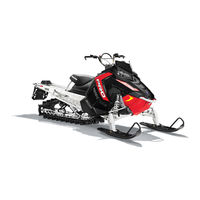
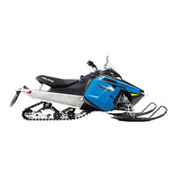
- Polaris IQ 550/600 Shift is a brand of a sports snowmobile with a throttle engine, which allows to reach a speed of 100 km / h with stable control.
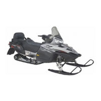
- Indy 600 SP — a machine with a powerful Liberty Cleafire engine with a capacity of 600 cc / cm. High engine performance is combined with low fuel consumption, thanks to the latter’s variable
injection system. - 600 RR — Race Replica snowmobile, model 2008, provides a fairly comfortable off-road driving. The machine is light, maneuverable, behaves stably at any speed.
- The 600 Rush is an innovative 2010 sports snowmobile. Almost all the latest proprietary developments are included in the design, the machine is characterized by an aggressive design and high
engine throttle response. - Rush 600 Pro-R is a popular 2011 model with an engine capacity of 125 liters. S., does not need an introduction. Sports contours are organically combined with a relatively low weight of 212
kilograms. - Switchback 600 Adventure — Polaris 600 SA snowmobile from the 2012 model line, features an elongated contour that allows you to place a 136-inch truck. The engine is two-stroke, well-proven
in racing. - Dragon 600/800 SP — sports snowmobile, 2009 release, created on the IQ platform. Available in two versions, with a forced motor and a calmer dynamics.
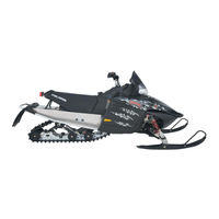
- 600/800 IQ — 2009 model, features a powerful motor that throws the car «straight off the bat.» Ideal for lovers of extreme driving.
- The Indy 800 SP is an excellent technical snowmobile with a lightweight and sturdy Pro-Ride chassis for easy handling at high speeds. Differs in engine efficiency.
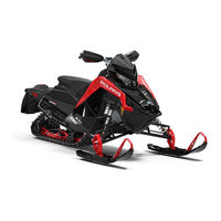
- Rush 800 Pro-R — one of the first Polaris snowmobiles, smoothly enters turns at speeds above 80 km / h while maintaining a sense of comfort.
- The Switchback 800 Pro-R is equipped with a 136-inch track, high-performance Walker Evans shock absorbers that are installed on all Pro-index vehicles. Model 800 features a wide, comfortable
seat. - 600 Dragon FST — the snowmobile has a truly draconian character, super-dynamic, although obedient to control. It is irreplaceable in races and in any other sports competitions.
- The IQ 700 is a sporty snowmobile with aggressive looks thanks to its 142 liter engine. with. provides the owner with a high level of adrenaline throughout the trip.
- IQ Shift — a wonderful tool for breathtaking journeys on the snowy plain, the extreme nature of the snowmobile will not let you get bored.
- Turbo IQ Dragon is a car from the 2009 lineup. Ideal for outdoor activities, sports competitions and just dizzying trips. A snowmobile driven by a 140 horsepower engine will always be ahead.
- Turbo IQ — a fast car for snowy spaces. Sporting performance is impeccable, the car runs smoothly and confidently in a given mode.
- Shift 550 136 is a universal machine for various activities in mountain conditions.
- 600 LX — comfortable and reliable mountain all-terrain vehicle. Equipped with an engine of 125 horsepower.
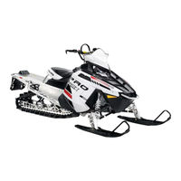
- 600 Pro-RMK — the snowmobile features a spring-hydraulic rear suspension with Walker Evans shock absorbers and other know-how.
- Shift 600 136 — a car designed for long trips, equipped with a powerful engine and a spacious fuel tank.
- Dragon 800 Switchback — the snowmobile of the increased comfort, differs in ease in management.

2007 TWO STROKE SNOWMOBILE
SERVICE MANUAL
FOREWORD
This service manual is designed primarily for use by certified Polaris Master Service Dealer technicians in a properly equipped shop and should be kept available for reference. All references to left and right side of the vehicle are from the operator’s perspective when seated in a normal riding position.
Some procedures outlined in this manual require a sound knowledge of mechanical theory, tool use, and shop procedures in order to perform the work safely and correctly. Technicians should read the text and be familiar with service procedures before starting the work. Certain procedures require the use of special tools. Use only the proper tools as specified.
Comments or suggestions about this manual may mailed to: Service Publications Dept. @ Polaris Sales Inc. 2100 Hwy
55 Medina Minnesota 55340.
You may also fill out a Comments and suggestion electronic form that can be located at
www.polarisdealers.com
in the
News, Forms & Links
area click on
Service & Warranty
link and the feedback link is at the bottom of the page named
Polaris Manual Correction Feedback
link.
2007 Two Stroke Snowmobile Service Manual PN 9920463
© Copyright 2006 Polaris Sales Inc. All information contained within this publication is based on the latest product information at the time of publication. Due to constant improvements in the design and quality of production components, some minor discrepancies may result between the actual vehicle and the information presented in this publication. Depictions and/or procedures in this publication are intended for reference use only. No liability can be accepted for omissions or inaccuracies. Any reprinting or reuse of the depictions and/or procedures contained within, whether whole or in part, is expressly prohibited. Printed in U.S.A.
UNDERSTANDING MANUAL SAFETY LABELS AND DIRECTIONS
Throughout this manual, important information is brought to your attention by the following symbols:
WARNING
SAFETY ALERT WARNING indicates a potential hazard that may result in severe injury or death to the operator, bystander or person(s) inspecting or servicing the vehicle.
CAUTION
SAFETY ALERT CAUTION indicates a potential hazard that may result in minor personal injury or damage to the vehicle.
CAUTION
CAUTION indicates special precautions that must be taken to avoid vehicle damage or property damage.
NOTE:
NOTE provides key information by clarifying instructions.
IMPORTANT:
IMPORTANT provides key reminders during disassembly, assembly and inspection of components.
=
In. / mm.
MEASUREMENT provides a key for a determined measurement specification.
=
T
TORQUE provides a key for a required torque value.
TRADEMARKS
POLARIS ACKNOWLEDGES THE FOLLOWING PRODUCTS MENTIONED IN THIS MANUAL:
Loctite, Registered Trademark of the Loctite Corporation
Nyogel, Trademark of Wm. F. Nye Co.
Fluke, Registered Trademark of John Fluke Mfg. Co.
Mity-Vac, Registered Trademark of Neward Enterprises, Inc.
Torx, Registered Trademark of Textron
M-10, Registerd Trademark of FAST, Inc
Some Polaris factory publications can be downloaded from www.polarisindustires.com, purchased from www.purepolaris.com or by contacting the nearest Polaris dealer.
SPECIFICATIONS
GENERAL
MAINTENANCE
FUEL DELIVERY
ENGINE
CLUTCHING
FINAL DRIVE
FRONT SUSPENSION
8
REAR SUSPENSION
9
CHASSIS/HOOD
ELECTRICAL
10
11
12
3
4
5
6
7
1
2
MODEL SPECIFICATIONS
CHAPTER 1
1
MODEL SPECIFICATIONS
340 LX . . . . . . . . . . . . . . . . . . . . . . . . . . . . . . . . . . . . . . . . . . . . . . . . . . . . . . . . . . . . . . . . 1.2
340 TOURING . . . . . . . . . . . . . . . . . . . . . . . . . . . . . . . . . . . . . . . . . . . . . . . . . . . . . . . . . . 1.4
WIDETRAK LX. . . . . . . . . . . . . . . . . . . . . . . . . . . . . . . . . . . . . . . . . . . . . . . . . . . . . . . . . . 1.6
500 XC SP . . . . . . . . . . . . . . . . . . . . . . . . . . . . . . . . . . . . . . . . . . . . . . . . . . . . . . . . . . . . . 1.8
SUPER SPORT . . . . . . . . . . . . . . . . . . . . . . . . . . . . . . . . . . . . . . . . . . . . . . . . . . . . . . . . 1.10
550 LX . . . . . . . . . . . . . . . . . . . . . . . . . . . . . . . . . . . . . . . . . . . . . . . . . . . . . . . . . . . . . . . 1.12
TRAIL RMK . . . . . . . . . . . . . . . . . . . . . . . . . . . . . . . . . . . . . . . . . . . . . . . . . . . . . . . . . . . 1.14
TRAIL TOURING DELUXE . . . . . . . . . . . . . . . . . . . . . . . . . . . . . . . . . . . . . . . . . . . . . . . 1.16
600 HO IQ . . . . . . . . . . . . . . . . . . . . . . . . . . . . . . . . . . . . . . . . . . . . . . . . . . . . . . . . . . . . 1.18
600 HO IQ CLEANFIRE. . . . . . . . . . . . . . . . . . . . . . . . . . . . . . . . . . . . . . . . . . . . . . . . . . 1.20
600 HO IQ LX CLEANFIRE . . . . . . . . . . . . . . . . . . . . . . . . . . . . . . . . . . . . . . . . . . . . . . . 1.22
600 HO SWITCHBACK . . . . . . . . . . . . . . . . . . . . . . . . . . . . . . . . . . . . . . . . . . . . . . . . . . 1.24
600 HO SWITCHBACK CLEANFIRE . . . . . . . . . . . . . . . . . . . . . . . . . . . . . . . . . . . . . . . 1.26
600 HO RMK 144/155 (F/O) . . . . . . . . . . . . . . . . . . . . . . . . . . . . . . . . . . . . . . . . . . . . . . 1.28
600 HO IQ TOURING CLEANFIRE . . . . . . . . . . . . . . . . . . . . . . . . . . . . . . . . . . . . . . . . . 1.30
DRAGON . . . . . . . . . . . . . . . . . . . . . . . . . . . . . . . . . . . . . . . . . . . . . . . . . . . . . . . . . . . . . 1.32
DRAGON RMK . . . . . . . . . . . . . . . . . . . . . . . . . . . . . . . . . . . . . . . . . . . . . . . . . . . . . . . . 1.34
1.1
MODEL SPECIFICATIONS
340 LX
MODEL S07ND3AS
Body
Body Style EDGE
Engine
Engine type
Engine displacement
Bore (in/mm)
Stroke (in/mm)
Piston to cylinder clearance (in/mm)
Piston ring end gap
(in/mm)
Operating RPM±200
Idle RPM±200
Clutch engagement RPM ±200
Fuji
339cc
2.45/62.3
2.19/55.6
.003-.005/.080-.130
.008-.014/.20-.41
7000
1600
4100
Fuel Delivery
Type
Main Jet
Pilot Jet
Jet Needle/Clip position
Needle Jet
Throttle gap under cutaway (in/mm)
Throttle slide cutaway
Valve seat
Starter jet
Pilot air jet
Fuel screw setting
Air screw setting
Recommended fuel octane (R+M/2)
VM30SS
170
35
5DP13/3
O-6 (169)
.240/6.1
2.5AL
1.5Viton
1.5
2.5
N/A
1.5
87 NonOxy Minimum
Altitude meters (feet)
Jetting
Ambient Temperature
0-600
(0-2000)
600-1200
(2000-4000)
1200-1800
(4000-6000)
1800-2400
(6000-8000)
2400-3000
(8000-10000)
3000-3700
(10000-12000)
185
#4
175
#3
165
#3
155
#3
145
#3
135
#3
170
#3
160
#3
155
#3
140
#3
130
#2
120
#2
180
#3
170
#3
160
#3
150
#3
140
#3
130
#2
165
#3
155
#3
145#
3
135
#2
125
#2
115
#1
170
#3
160
#3
150
#3
135
#3
130
#2
115
#2
160
#3
150
#3
140
#2
130
#2
120
#1
110
#1
150
#3
140
#2
130
#2
120
#1
110
#1
100
#1
155
#3
140
#2
130
#2
120
#1
110
#1
100
#1
Clutching
Altitude meters
(feet)
0-900
(0-3000)
900-1800
(3000-6000)
Drive Clutch (P-85)
Shift
Weight
Clutch
Spring
10
10-M
Blue
110/290
(Black-
2287)
110/290
(Black-
2287)
Driven Clutch (TEAM)
Clutch
Spring
Driven
Helix
Gearing
Red/
Black
Red/
Black
S36 LW
ER
S36 LW
ER
1800-2700 (6000-
9000)
2700-3700 (9000-
12000)
10MW
10MR
110/290
(Black-
2287)
110/290
(Black-
2287)
Red/
Black
Red/
Black
S36 LW
ER
S36 LW
ER
Drive clutch bolt torque 50 ft-lbs (69 N-m)
16:41-72
16:41-72
16:41-72
16:41-72
Belt part number
Belt width (in/cm)
Belt side angle
Outside diameter (in/cm)
Clutch center distance (in/cm)
Belt
Chaincase
3211078
1.438/3.65
28°
46.625/118.4
11.5/29.2
Center distance (in/cm)
Reverse type
7.92/20.1
PERC
1.2
Fluids and Capacities
Fuel (gal/l)
Oil (qts/l)
Coolant (qts/l)
Chaincase (oz/ml)
Brake fluid type
11.8/44.7
3.25/3.1
N/A
9/266.2
DOT4
Track
Width (in/cm)
Length (in/cm)
Lug height (in/cm)
Manufacture
Track tension sag (in/cm) with 10 lbs/
4.54kg placed 16 in/40.6cm ahead of rear idler shaft
15/38
121/307
.66/1.7
Camoplast
.375-.5/1-1.3
Front Suspension
Suspension type
IFS shocks
IFS Spring PN
IFS Spring Pre-Load (in/mm)
IFS spring rate (lb/in — kg/mm)
IFS Spring free length (in/cm)
Front vertical travel (in/cm)
Ski center distance (in/cm)
Camber (in/mm)
Toe (in/mm)
Edge LX
Arvin/7041932
7041551
.625/15.9
100/1.79
10.75/27.3
10/25.4
42.5/108
.59±.31/15.0±7.9
.12-.25/3.0-6.35
Rear Suspension
Suspension type
Front track shock (FTS)
FTS Spring PN
FTS Spring Free Length (in/cm)
FTS Spring Rate (lb/in — kg/mm)
FTS pre-load
Rear track shock
Rear travel (in/cm)
Edge 121
Arvin/7041939
7041253
7.5/19
200-240/3.6-4.3
Fixed
Arvin MPV/7043239
13.9/35.3
Torsion Spring
Torsion spring PNs (LH/RH)
Torsion spring diameter (in/mm)
Torsion spring tail angle
7041629/7041630
.359/9.12
77°
MODEL SPECIFICATIONS
Dimensions
Width (in/cm)
Length (in/cm)
Height (in/cm)
Est dry weight (lb/kg)
Ignition timing
Spark plug gap (in/mm)
Spark plug
Voltage regulator/output
CDI marking
Flywheel Markings
Electrical
Features
Electric Fuel Gauge
Electric Start
Low Oil Light
Parking Brake
Speedometer
Tachometer
48/122
113/287
46/117
457/207.7
26.5°@3000RPM
.0275/.70
NGK BR8ES
240watt
CU7245
FP9313
Accessory
Standard
Standard
Standard
Standard 5 inch
Accessory
1
1.3
MODEL SPECIFICATIONS
340 TOURING
MODEL S07NT3A(E,S)
Body
EDGE Body Style
Engine
Engine type
Engine displacement
Bore (in/mm)
Stroke (in/mm)
Piston to cylinder clearance (in/mm)
Piston ring end gap
(in/mm)
Operating RPM±200
Idle RPM±200
Clutch engagement RPM ±200
Fuji
339cc
2.45/62.3
2.19/55.6
.003-.005/.080-.130
.008-.014/.20-.41
7000
1600
3700
Fuel Delivery
Type
Main Jet
Pilot Jet
Jet Needle/Clip position
Needle Jet
Throttle gap under cutaway (in/mm)
Throttle slide cutaway
Valve seat
Starter jet
Pilot air jet
Fuel screw setting
Air screw setting
Recommended fuel octane (R+M/2)
VM30SS
170
35
5DP13/3
O-6(169)
.240/6.1
2.5AL
1.5 Viton
1.5
2.5
N/A
1.5
87 non Oxy/Minimum
Altitude meters (feet)
Jetting
Ambient Temperature
0-600
(0-2000)
600-1200
(2000-4000)
1200-1800 (4000-
6000)
1800-2400 (6000-
8000)
2400-3000
(8000-10000)
3000-3700
(10000-12000)
185
#4
175
#3
165
#3
155
#3
145
#3
135
#3
180
#3
170
#3
160
#3
150
#3
140
#3
130
#2
170
#3
160
#3
155
#3
140
#3
130
#2
120
#2
165
#3
155
#3
145
#3
135
#2
125
#2
115
#1
170
#3
160
#3
150
#3
135
#3
130
#2
115
#2
160
#3
150
#3
140
#2
130
#2
120
#1
110
#1
150
#3
140
#2
130
#2
120
#1
110
#1
100
#1
155
#3
140
#2
130
#2
120
#1
110
#1
100
#1
Clutching
Altitude meters
(feet)
0-900
(0-3000)
900-1800
(3000-6000)
Drive Clutch (P-85)
Shift
Weight
Clutch
Spring
10
10-M
Blue
(110/290)
Black-
2287
(110-290)
Black-
2287
Driven Clutch (TEAM)
Clutch
Spring
Driven
Helix
Gearing
Blue/
Black
Blue/
Black
54/38-25
LW ER
54/38-25
LW ER
1800-2700 (6000-
9000)
2700-3700 (9000-
12000)
10 MW
10 MR
(110-290)
Black-
2287
(110-290)
Black-
2287
Blue/
Black
Blue/
Black
54/38-25
LW ER
54/38-25
LW ER
Drive clutch bolt torque 50 ft-lbs(69 N-m)
17:41-72
17:41-72
17:41-72
17:41-72
Belt part number
Belt width (in/cm)
Belt side angle
Outside diameter (in/cm)
Clutch center distance (in/cm)
Belt
Chaincase
3211078
1.438/3.65
28
°
46.625/118.4
11.5/29.2
Center distance (in/cm)
Reverse type
7.92/20.1
PERC
1.4
Fluids and Capacities
Fuel (gal/l)
Oil (qts/l)
Coolant (qts/l)
Chaincase (oz/ml)
Brake fluid type
12.25/46.4
3.25/3.1
N/A
9/266.2
DOT 4
Track
Width (in/cm)
Length (in/cm)
Lug height (in/cm)
Manufacture
Track tension sag (in/cm) with 10 lbs/
4.54kg placed 16 in/40.6cm ahead of rear idler shaft
15/38
136/345
1/2.5
Soucy
1.125 — 1.375 / 2.9 — 3.5
Front Suspension
Suspension type
IFS shocks
IFS Spring PN
IFS Spring Pre-Load (in/mm)
IFS spring rate (lb/in — kg/mm)
IFS Spring free length (in/cm)
Front vertical travel (in/cm)
Ski center distance (in/cm)
Camber (in/mm)
Toe (in/mm)
Edge LX
Arvin/7041932
7041551
.625/15.9
100/1.79
10.75/27.3
10/25.4
42.5/108
.59±.31/15.0±7.9
.12-.25/3.0-6.35
Rear Suspension
Suspension type
Front track shock (FTS)
FTS spring rate (lb/in — kg/mm)
FTS spring installed length (in/cm)
Rear track shock
Rear travel (in/cm)
Edge 136
Arvin/7041939
200-240/3.6-4.3
Fixed
Arvin/7042138
13.9/35.3
Torsion Spring
Torsion spring PNs
(LH/RH)
Torsion spring diameter (in/mm)
Torsion spring tail angle
7041940/7041941
.405/10.3
77°
MODEL SPECIFICATIONS
Dimensions
Width (in/cm)
Length (in/cm)
Height (in/cm)
Est dry weight lb/kg
Ignition timing
Spark plug gap (in/mm)
Spark plug
Voltage regulator/output
CDI marking
Flywheel Marking
Electrical
Features
47.25/120
128/325.1
49.5/125.7
517/234.7
26.5°@3000RPM
.028/.70
NGK BR8ES
240watt
CU7245
FP9319
Electric Fuel Gauge
Electric Start
Low Oil Light
Parking Brake
Speedometer
Tachometer
Accessory
Standard
Standard
Standard
Standard 5 inch
Accessory
1
1.5
MODEL SPECIFICATIONS
WIDETRAK LX
MODEL S07SU4BS
Body
Body Style
Engine
Engine type
Engine displacement
Engine model number
Bore (in/mm)
Stroke (in/mm)
Piston to cylinder clearance (in/mm)
Piston ring end gap (in/mm)
Operating RPM±200
Idle RPM±200
Clutch engagement RPM ±200
GENII
Fuji
488cc
EC50PL237
2.83/72
2.36/60
.0035-.0049/.090-.125
.0070-.016/.20-.47
7000
1600
3800
Fuel Delivery
Type
Main Jet
Pilot Jet
Jet Needle/Clip position
Needle Jet
Throttle gap under cutaway (in/mm)
Throttle slide cutaway
Valve seat
Starter jet
Pilot air jet
Fuel screw setting
Air screw setting
Recommended fuel octane (R+M/2)
VM34SS
195
35
6EJ26/2
P-6 (166)
.240/6.1
3
1.5 Viton
1.5
N/A
N/A
.5
87 NonOxy/Minimum
Altitude meters (feet)
Jetting
Ambient Temperature
0-600
(0-2000)
600-1200
(2000-4000)
1200-1800
(4000-6000)
1800-2400
(6000-8000)
210
#2
195
#2
185
#2
170
#2
200
#2
185
#2
175
#2
165
#2
195
#2
180
#2
170
#2
155
#2
190
#2
175
#2
165
#2
155
#1
185
#2
170
#2
160
#1
150
#1
175
#2
165
#2
155
#1
140
#1
170
#2
155
#1
145
#1
135
#1
2400-3000
(8000-10000)
3000-3700
(10000-12000)
160
#2
150
#2
155
#2
140
#1
145
#1
135
#1
145
#1
130
#1
140
#1
125
#1
130
#1
120
#1
120
#1
110
#1
120
#1
110
#1
When using non oxygenated fuel with an octane number greater than 93, decrease the main jet number in the above chart by 5
170
#1
155
#1
145
#1
135
#1
Clutching
Altitude meters
(feet)
Drive Clutch (P-85)
Shift
Weight
Clutch
Spring
Driven Clutch (P-85)
Clutch
Spring
Driven
Helix
Gearing
0-900
(0-3000)
900-1800
(3000-6000)
1800-2700
(6000-9000)
2700-3700
(9000-12000)
10
10
10-M
Blue
10 MW
Brown
Red/
White
Red/
White
Red/
White
Silver
Silver
Silver
Silver
36D #2
36D #2
36D #2
36D #2
Drive clutch bolt torque 50 ft-lbs (69 N-m)
19:41-66
19:41-66
19:41-66
19:41-66
Belt part number
Belt width (in/cm)
Belt side angle
Outside diameter (in/cm)
Clutch center distance (in/cm)
Belt
3211070
1.375/3.49
28°
47.25/120
12/30.5
Chaincase
Center distance (in/cm)
Reverse type
N/A
Hi/Low/Reverse
1.6
Fuel (gal/l)
Oil (qts/l)
Coolant (qts/l)
Gearcase (oz/ml)
Brake fluid type
Fluids and Capacities
11/41.6
2/1.9
3.4/3.2
20/591.5
DOT4
Track
Width (in/cm)
Length (in/cm)
Lug height (in/cm)
Manufacture
Track tension sag (in/cm) with 10 lbs/
4.54kg placed 16 in/40.6cm ahead of rear idler shaft
20/51
156/396
1/2.5
Camoplast
.75-1.0/1.9-2.5
Front Suspension
Suspension type
IFS shocks
IFS spring rate (lb/in — kg/mm)
Spring installed length (in/cm)
Front vertical travel (in/cm)
Ski center distance (in/cm)
Camber (in/mm)
Toe (in/mm)
WideTrak GenII
Arvin/7041535
105/1.9
Fixed
7.25/18.4
38/96.5
.82±.72/20.8±18.3
0-.12/0-3
Rear Suspension
Suspension type
Front track shock (FTS)
FTS spring rate
lbs-in/kg-mm
FTS spring installed length (in/cm)
Rear track shock
Rear travel (in/cm)
WideTrak
Arvin 7041742
181/3.2
Fixed
Arvin/7042309
9/22.9
Torsion Spring
Torsion spring PNs
(LH/RH)
Torsion spring diameter (in/mm)
Torsion spring tail angle
7041239/7041240
.468/11.9
74
°
MODEL SPECIFICATIONS
Dimensions
Width (in/cm)
Length (in/cm)
Height (in/cm)
Est dry weight lb/kg
Ignition timing
Spark plug gap (in/mm)
Spark plug
Voltage regulator/output
CDI marking
Flywheel Marking
Electrical
Features
Electric Fuel Gauge
Electric Start
Low Oil Light
Parking Brake
Speedometer
Tachometer
43.5/110
128/325
51/130
643/291.9
28°@3000
.028/.71
Champion RN3C
200watt
IU2212
FP5536
N/A
Standard
Standard
N/A
Standard 5 inch
Accessory
1
1.7
MODEL SPECIFICATIONS
500 XC SP
MODEL S07NP5CS(E)
Body
EDGE Body Style
Engine
Engine type
Engine displacement
Engine model number
Bore (in/mm)
Stroke (in/mm)
Piston to cylinder clearance (in/mm)
Piston ring end gap
(in/mm)
Operating RPM±200
Idle RPM
Clutch engagement RPM +/- 200
Exhaust valve spring
Liberty
500
S3033-5044-PF5F
2.78/70.5
2.52/64
.0045-.0059/.11-.15
.014-.020/.40-.61
8500
1500
4200
Pink/Yellow
Fuel Delivery
Type
Main Jet
Pilot Jet
Jet Needle/Clip position
Needle Jet
Throttle gap under cutaway (in/mm)
Throttle slide cutaway
Valve seat
Starter jet
Pilot air jet
Fuel screw setting
Air screw setting
Recommended fuel octane (R+M/2)
TM38
410
45
6BGY41/4
P-8
.079/2
2
1.5
145
N/A
3
1.25
87 Min NonOxy
Altitude meters (feet)
Jetting
Ambient Temperature
0-600
(0-2000)
600-1200
(2000-4000)
1200-1800 (4000-
6000)
1800-2400 (6000-
8000)
440
#3
420
#3
390
#2
370
#2
430
#3
400
#2
380
#2
350
#2
410
#2
390
#2
360
#2
340
#2
400
#2
370
#2
350
#2
320
#2
390
#2
360
#2
340
#2
310
#1
380
#2
250
#2
330
#1
300
#1
360
#2
330
#1
310
#1
290
#1
2400-3000
(8000-10000)
340
#2
330
#2
310
#1
300
#1
290
#1
280
#1
260
#1
250
#1
3000-3700
(10000-12000)
320
#1
300
#1
290
#1
270
#1
260
#1
250
#1
240
#1
230
#1
When using non oxygenated fuel with an octane number greater than 93, decrease the main jet number in the above chart by 20.
350
#1
320
#1
300
#1
270
#1
Clutching
Altitude meters
(feet)
0-900
(0-3000)
900-1800
(3000-6000)
1800-2700 (6000-
9000)
2700-3700 (9000-
12000)
Drive Clutch (P-85)
Shift
Weight
Clutch
Spring
10-56
10-54
Black/
Green
Black/
Green
10
10M Blue
Black/
Green
Black/
Green
Driven Clutch (TEAM)
Clutch
Spring
Driven
Helix
Gearing
Red/
Black
Red/
Black
56/42-36
LW ER
56/42-36
LW ER
22:40-74
22:40-74
Red/
Black
Red/
Black
56/42-36
LW ER
56/42-36
LW ER
21:40-74
21:40-74
Drive clutch bolt torque 50 ft-lbs (69 N-m)
Belt part number
Belt width (in/cm)
Belt side angle
Outside diameter (in/cm)
Clutch center distance (in/cm)
Belt
3211080
1.438/3.65
28°
46.625/118.4
11.5/29.2
Chaincase
Center distance (in/cm)
Reverse type
7.92/20.1
PERC
1.8
Fluids and Capacities
Fuel (gal/l)
Oil (qts/l)
Coolant (qts/l)
Chaincase (oz/ml)
Brake fluid type
11.8/44.7
3.25/3.1
5.6/5.3
9/266.2
DOT4
Track
Width (in/cm)
Length (in/cm)
Lug height (in/cm) [Euro]
Manufacture
Track tension sag (in/cm) with 10 lbs/
4.54kg placed 16 in/40.6cm ahead of rear idler shaft
15/38
121/307
.91/2.3 [1.25/31.75]
Camoplast
.375-.5/1-1.3
Front Suspension
Suspension type
IFS shocks
IFS spring rate (lb/in — kg/mm)
IFS Spring installed length (in/cm)
Front vertical travel (in/cm)
Ski center distance (in/cm)
Camber (in/mm)
Toe (in/mm)
Edge
Arvin/7043082
68-160/1.22-2.9
10.5/26.7
10.3/26.2
42.5/108
.59±.31/15.0±7.9
.12-.25/3.0-6.35
Rear Suspension
Suspension type
Front track shock
FTS Spring rate (lb/in — kg/mm)
FTS Spring installed length
Rear track shock
Rear travel (in/cm)
Edge 121
Arvin/7041975
160 Var/2.86 Var
7.46/18.9
Arvin MPV/7043239
13.9/35.3
Torsion Spring
Torsion spring PNs
(LH/RH)
Torsion spring diameter (in/mm)
Torsion spring tail angle
7041942/7041943
.375/9.5
77°
MODEL SPECIFICATIONS
Dimensions
Width (in/cm)
Length (in/cm)
Height (in/cm)
Est dry weight lb/kg
Ignition timing
Spark plug gap (in/mm)
Spark plug
Voltage regulator/output
CDI marking
Flywheel Marking
Electrical
25°@2500RPM
.027/.70
Champion RN57YCC
280watt
4010829
4010677
Features
48/122
113/287
46/117
481/218.4
Electric Fuel Gauge
Electric Start
Low Oil Light
Parking Brake
Speedometer
Tachometer
Accessory
Accessory
Standard
Standard
Standard 5 inch
Standard 5 inch
1
1.9
MODEL SPECIFICATIONS
Body Style
SUPER SPORT
MODEL S07NP5B(E,S)
Body
EDGE
Engine
Engine type
Engine Model
Engine Displacement
Bore (in/mm)
Stroke (in/mm)
Piston to cylinder clearance (in/mm)
Piston ring end gap
(in/mm)
Operating RPM±200
Idle RPM±200
Clutch engagement RPM ±200
Exhaust valve spring
Fuji
EC550PM100
544cc
2.87/73
2.56/65
.0039-.0053/.10-.135
.016-.022/.40-.55
7000
1600
3800
N/A
Fuel Delivery
Type
Main Jet
Pilot Jet
Jet Needle/Clip position
Needle Jet
Throttle gap under cutaway (in/mm)
Throttle slide cutaway
Valve seat
Starter jet
Pilot air jet
Fuel screw setting
Air screw setting
Recommended fuel octane (R+M/2)
VM34
250
35
6DEH11/3
Q-0 (480)
.256/6.5
3
1.5 Viton
1.5
2.5
N/A
1.0
87 NonOxy/Min.
Altitude meters (feet)
Jetting
Ambient Temperature
0-600
(0-2000)
600-1200
(2000-4000)
1200-1800
(4000-6000)
1800-2400
(6000-8000)
2400-3000
(8000-10000)
3000-3700
(10000-12000)
260
#4
250
#4
240
#3
220
#3
210
#3
200
#2
270
#4
260
#4
250
#4
230
#3
220
#3
210
#3
250
#4
240
#3
240
#3
230
#3
220
#3
230
#3
220
#3
210
#2
210
#2
190
#2
200
#2
190
#1
230
#3
220
#3
210
#2
210
#2
190
#1
180
#1
220
#3
210
#2
220
#2
210
#2
200
#1
210
#2
200
#1
190
#1
190
#1
180
#1
180
#1
170
#1
200
#1
200
#1
190
#1
180
#1
170
#1
160
#1
Clutching
Altitude meters
(feet)
0-600
(0-2000)
600-1200
(2000-4000)
1200-1800
(4000-6000)
1800-2400
(6000-8000)
2400-3000
8000-10000)
3000-3600
(10000-12000)
Drive Clutch (P-85)
Shift
Weight
Clutch
Spring
10-62
10-60
Dark Blue/
White
Dark Blue/
White
10-60
10-58
10-56
10-56
Dark Blue/
White
Dark Blue/
White
Dark Blue/
White
Dark Blue/
White
Driven Clutch (TEAM)
Clutch
Spring
Driven
Helix
Gearing
Red/Blue
Red/Blue
(56/42-.36)
LW ER
(56/42-.36)
LW ER
19:39- 72
19:39- 72
Red/Blue
Red/Blue
Red/Blue
Red/Blue
(56/42-.36)
LW ER
(56/42-.36)
LW ER
(56/42-.36)
LW ER
(56/42-.36)
LW ER
19:39- 72
18:39- 72
18:39- 72
18:39- 72
Drive clutch bolt torque 50 ft-lbs (69 N-m)
Belt part number
Belt width (in/cm)
Belt side angle
Outside diameter (in/cm)
Clutch center distance (in/cm)
Belt
Chaincase
Center distance (in/cm)
Reverse type
3211078
1.438/3.65
28°
46.625/118.4
11.5/29.2
7.92/18.52
PERC
1.10
Fluids and Capacities
Fuel (gal/l)
Oil (qts/l)
Coolant (qts/l)
Chaincase (oz/ml)
Brake fluid type
11.8/44.7
3.25/3.1
N/A
9/266.2
DOT4
Track
Width (in/cm)
Length (in/cm)
Lug height (in/cm)
Manufacturer
Track tension sag (in/cm) with 10 lbs/
4.54kg placed 16 in/40.6cm ahead of rear idler shaft
15/38
121/307
.82/2.1
Camoplast
.375-.5/1-1.3
Front Suspension
Suspension type
IFS shocks
IFS spring rate (lb/in — kg/mm)
Spring preload (in/cm)
Front vertical travel (in/cm)
Ski center distance (in/cm)
Camber (in/mm)
Toe (in/mm)
Edge
Arvin/7041932
100/1.79
.625/15.875
10/25.4
42.5/108
.59±.31/15.0±7.9
.12-.25/3.0-6.35
Rear Suspension
Suspension type
Front track shock (FTS)
FTS spring rate (lb/in — kg/mm)
FTS spring installed length (in/cm)
Rear track shock
Rear travel (in/cm)
Edge 121
Arvin/7041939*
200-240 / 3.6 — 4.4Var
Fixed
Arvin MPV/7043239
13.9/35.3
* notes that shock is serviceable
Torsion Spring
Torsion spring PNs
(LH/RH)
Torsion spring diameter (in/mm)
Torsion spring tail angle
7041942/7041943
.375/9.5
77°
Dimensions
Width (in/cm)
Length (in/cm)
Height (in/cm)
48/122
113/287
45/114
MODEL SPECIFICATIONS
Dimensions
Est dry weight lb/kg
Ignition timing
Spark plug gap (in/mm)
Spark plug
Voltage regulator/output
CDI marking
Flywheel Marking
Electrical
Features
Electric Fuel Gauge
Electric Start
Low Oil Light
Parking Brake
Speedometer
Tachometer
460/208.7
27°@3000
.028/.70
NGK BR9ES
280watt
EC55PM 100/110
FP6318
Accessory
Accessory
Standard
Standard
Standard 5 inch
Accessory
1
1.11
MODEL SPECIFICATIONS
550 LX
MODEL S07ND5BS
Body
Body Style EDGE
Engine
Engine type
Engine Model
Engine Displacement
Bore (in/mm)
Stroke (in/mm)
Piston to cylinder clearance (in/mm)
Piston ring end gap
(in/mm)
Operating RPM±200
Idle RPM±200
Clutch engagement RPM ±200
Exhaust valve spring
Fuji
EC550PM110
544cc
2.87/73
2.56/65
.0039-.0053/.10-.135
.016-.022/.40-.61
7000
1600
3800
N/A
Fuel Delivery
Type
Main Jet
Pilot Jet
Jet Needle/Clip position
Needle Jet
Throttle gap under cutaway (in/mm)
Throttle slide cutaway
Valve seat
Starter jet
Pilot air jet
Fuel screw setting
Air screw setting
Recommended fuel octane (R+M/2)
VM34
250
35
6BGY41/4
Q-0 (480)
.256/6.5
3
1.5 Viton
1.5
2.5
N/A
1.0
87 NonOxy/Min.
Altitude meters (feet)
Jetting
Ambient Temperature
0-600
(0-2000)
600-1200
(2000-4000)
1200-1800
(4000-6000)
1800-2400
(6000-8000)
2400-3000
(8000-10000)
3000-3700
(10000-12000)
260
#4
250
#4
240
#3
220
#3
210
#3
200
#2
270
#4
260
#4
250
#4
230
#3
220
#3
210
#3
250
#4
240
#3
240
#3
230
#3
220
#3
230
#3
220
#3
210
#2
210
#2
190
#2
200
#2
190
#1
230
#3
220
#3
210
#2
210
#2
190
#1
180
#1
220
#3
210
#2
220
#2
210
#2
200
#1
210
#2
200
#1
190
#1
190
#1
180
#1
180
#1
170
#1
200
#1
200
#1
190
#1
180
#1
170
#1
160
#1
Clutching
Altitude meters
(feet)
0-600
(0-2000)
600-1200
(2000-4000)
1200-1800
(4000-6000)
1800-2400
(6000-8000)
2400-3000
8000-10000)
3000-3600
(10000-12000)
Drive Clutch (P-85)
Shift
Weight
Clutch
Spring
10-62
10-60
Dark Blue/
White
Dark Blue/
White
10-60
10-58
10-56
10-56
Dark Blue/
White
Dark Blue/
White
Dark Blue/
White
Dark Blue/
White
Driven Clutch (TEAM)
Clutch
Spring
Driven
Helix
Gearing
Red/Blue
Red/Blue
(56/42-.36)
LW ER
(56/42-.36)
LW ER
19:39- 72
19:39- 72
Red/Blue
Red/Blue
Red/Blue
Red/Blue
(56/42-.36)
LW ER
(56/42-.36)
LW ER
(56/42-.36)
LW ER
(56/42-.36)
LW ER
19:39- 72
18:39- 72
18:39- 72
18:39- 72
Drive clutch bolt torque 50 ft-lbs (69 N-m)
Belt part number
Belt width (in/cm)
Belt side angle
Outside diameter (in/cm)
Clutch center distance (in/cm)
Belt
Chaincase
Center distance (in/cm)
Reverse type
3211078
1.438/3.65
28°
46.625/118.4
11.5/29.2
7.92/18.52
PERC
1.12
Fluids and Capacities
Fuel (gal/l)
Oil (qts/l)
Coolant (qts/l)
Chaincase (oz/ml)
Brake fluid type
11.8/44.7
3.25/3.1
N/A
9/266.2
DOT4
Track
Width (in/cm)
Length (in/cm)
Lug height (in/cm)
Manufacturer
Track tension sag (in/cm) with 10 lbs/
4.54kg placed 16 in/40.6cm ahead of rear idler shaft
15/38
121/307
.82/2.1
Camoplast
.375-.5/1-1.3
Front Suspension
Suspension type
IFS shocks
IFS spring rate (lb/in — kg/mm)
Spring preload (in/cm)
Front vertical travel (in/cm)
Ski center distance (in/cm)
Camber (in/mm)
Toe (in/mm)
Edge
Arvin/7041932
100/1.79
.625/15.875
10/25.4
42.5/108
.59±.31/15.0±7.9
.12-.25/3.0-6.35
Rear Suspension
Suspension type
Front track shock (FTS)
FTS spring rate (lb/in — kg/mm)
FTS spring installed length (in/cm)
Rear track shock
Rear travel (in/cm)
Edge 121
Arvin/7041939*
200-240 / 3.6 — 4.4Var
Fixed
Arvin MPV/7043239
13.9/35.3
* notes that shock is serviceable
Torsion Spring
Torsion spring PNs
(LH/RH)
Torsion spring diameter (in/mm)
Torsion spring tail angle
7041629/7041630
.375/9.5
77°
Dimensions
Width (in/cm)
Length (in/cm)
Height (in/cm)
48/122
113/287
45/114
MODEL SPECIFICATIONS
Dimensions
Est dry weight lb/kg 460/208.7
1
Electrical
Ignition timing
Spark plug gap (in/mm)
Spark plug
Voltage regulator/output
CDI marking
Flywheel Marking
27°@3000
.028/.70
NGK BR9ES
280watt
EC55PM 100/110
FP6318
Features
Electric Fuel Gauge
Electric Start
Low Oil Light
Parking Brake
Speedometer
Tachometer
Accessory
Standard
Standard
Standard
Standard 5 inch
Accessory
1.13
MODEL SPECIFICATIONS
TRAIL RMK
MODEL S07NJ5B(E,S)
Body
EDGE Body Style
Engine
Engine type
Engine Model
Engine displacement
Bore (in/mm)
Stroke (in/mm)
Piston to cylinder clearance (in/mm)
Piston ring end gap (in/mm)
Operating RPM±200
Idle RPM
Clutch engagement RPM ±200
Fuji
EC550PM110
544cc
2.87/73
2.56/65
.0039-.005/.10-.135
.016-.022/.4-.61
7000
1600
3800
Fuel Delivery
Type
Main Jet
Pilot Jet
Jet Needle/Clip position
Needle Jet
Throttle gap under cutaway (in/mm)
Throttle slide cutaway
Valve seat
Starter jet
Pilot air jet
Fuel screw setting
Air screw setting
Recommended fuel octane (R+M/2)
VM34
210
35
6BGY41/4
Q-0 (480)
.264/6.71
3
1.5 Viton
1.5
2.5
N/A
.75
87 NonOxy/Min.
Altitude meters (feet)
Jetting
Ambient Temperature
0-600
(0-2000)
600-1200
(2000-4000)
1200-1800
(4000-6000)
1800-2400
(6000-8000)
2400-3000
(8000-10000)
3000-3700
(10000-12000)
260
#4
250
#4
240
#3
220
#3
210
#3
200
#2
270
#4
260
#4
250
#4
230
#3
220
#3
210
#3
250
#4
240
#3
240
#3
230
#3
220
#3
230
#3
220
#3
210
#2
210
#2
190
#2
200
#2
190
#1
230
#3
220
#3
210
#2
210
#2
190
#1
180
#1
220
#3
210
#2
220
#3
210
#2
200
#1
210
#2
200
#1
190
#1
190
#1
180
#1
180
#1
170
#1
200
#1
200
#1
190
#1
180
#1
170
#1
160
#1
Clutching
Altitude meters
(feet)
0-600
(0-2000)
600-1200
(2000-4000)
1200-1800
(4000-6000)
1800-2400
(6000-8000)
2400-3000
8000-10000)
3000-3600
(10000-12000)
Drive Clutch (P-85)
Shift
Weight
Clutch
Spring
10-64
10-62
Dark Blue/
White
Dark Blue/
White
10-60
10-60
10-58
10-56
Dark Blue/
White
Dark Blue/
White
Dark Blue/
White
Dark Blue/
White
Driven Clutch (TEAM)
Clutch
Spring
Driven
Helix
Gearing
Red/Blue
Red/Blue
(56/42-.36)
LW ER
(56/42-.36)
LW ER
19:43- 74
19:43- 74
Red/Blue
Red/Blue
Red/Blue
Red/Blue
(56/42-.36)
LW ER
(56/42-.36)
LW ER
(56/42-.36)
LW ER
(56/42-.36)
LW ER
19:43- 74
19:43- 74
19:43- 74
19:43- 74
Drive clutch bolt torque 50 ft-lbs (69 N-m)
Belt part number
Belt width (in/cm)
Belt side angle
Outside diameter (in/cm)
Clutch center distance (in/cm)
Belt
3211078
1.438/3.65
28°
46.625/118.4
11.5/29.2
1.14
Chaincase
Center distance (in/cm)
Reverse type
7.92/20.1
PERC
Fluids and Capacities
Fuel (gal/l)
Oil (qts/l)
Coolant (qts/l)
Chaincase (oz/ml)
Brake fluid type
11.8/44.7
3.25/3.1
Air
9/266.2
DOT 4
Track
Width (in/cm)
Length (in/cm)
Lug height (in/cm)
Manufacturer
Track tension sag (in/cm) with 10 lbs/
4.54kg placed 16 in/40.6cm ahead of rear idler shaft
15/38
136/345
1.25/3.2
Camoplast
.375-.50/1-1.3
Front Suspension
Suspension type
IFS shocks
IFS spring rate (lb/in — kg/mm)
Spring installed length (in/cm)
Front vertical travel (in/cm)
Ski center distance (in/cm)
Camber (in/mm)
Toe (in/mm)
Edge RMK
Arvin/7042107
80/1.4
9.75/24.8
7.6/19.3
41/104
.735±.31/18.7±7.9
0-.12
Rear Suspension
Suspension type
Front track shock
FTS spring rate (lb/in — kg/mm)
FTS spring installed length (in/cm)
Rear track shock
Rear travel (in/cm)
Edge RMK 136
Arvin/7042085
170/3.0
Fixed
7042058
13.8/35.1
MODEL SPECIFICATIONS
Torsion Spring
Torsion spring PNs
(LH/RH)
Torsion spring diameter (in/mm)
Torsion spring tail angle
7041627/7041628
.347/8.8
77°
Dimensions
Width (in/cm)
Length (in/cm)
Height (in/cm)
Est dry weight lb/kg
45.5/115.6
124/315
48/123
475/215.7
Electrical
Ignition timing
Spark plug gap (in/mm)
Spark plug
Voltage regulator/output
CDI marking
Flywheel marking
27°@3000 RPM
14°@6500RPM
.028/.70
NGK BR9ES
280 watts
EC55PM100/110
FP6318
Features
Electric Fuel Gauge
Electric Start
Low Oil Light
Parking Brake
Speedometer
Tachometer
Accessory
Standard
Standard
Standard
Standard 5 inch
Accessory
1
1.15
MODEL SPECIFICATIONS
TRAIL TOURING DELUXE
MODEL S07NT5B(E,S)(A)
Body
Body Style EDGE
Engine
Engine type
Engine Model
Engine displacement
Bore (in/mm)
Stroke (in/mm)
Piston to cylinder clearance (in/mm)
Piston ring end gap
(in/mm)
Operating RPM±200
Idle RPM
Clutch engagement RPM ±200
Fuji
EC550PM100
544cc
2.87/73
2.56/65
.0039-.005/.10-.135
.016-.022/.4-.61
7000
1600
3800
Fuel Delivery
Type
Main Jet
Pilot Jet
Jet Needle/Clip position
Needle Jet
Throttle gap under cutaway (in/mm)
Throttle slide cutaway
Valve seat
Starter jet
Pilot air jet
Fuel screw setting
Air screw setting
Recommended fuel octane (R+M/2)
VM34
250
35
6BGY41/4
Q-0 (480)
.256/6.5
3
1.5 Viton
1.5
2.5
N/A
1.0
87 NonOxy/Min.
Altitude meters (feet)
Jetting
Ambient Temperature
0-600
(0-2000)
600-1200
(2000-4000)
1200-1800
(4000-6000)
1800-2400
(6000-8000)
2400-3000
(8000-10000)
3000-3700
(10000-12000)
260
#4
250
#4
240
#3
220
#3
210
#3
200
#2
270
#4
260
#4
250
#4
230
#3
220
#3
210
#3
250
#4
240
#3
240
#3
230
#3
220
#3
230
#3
220
#3
210
#2
210
#2
190
#2
200
#2
190
#1
230
#3
220
#3
210
#2
210
#2
190
#1
180
#1
220
#3
210
#2
220
#3
210
#2
200
#1
210
#2
200
#1
190
#1
190
#1
180
#1
180
#1
170
#1
200
#1
200
#1
190
#1
180
#1
170
#1
160
#1
Clutching
Altitude meters
(feet)
0-600
(0-2000)
600-1200
(2000-4000)
1200-1800
(4000-6000)
1800-2400
(6000-8000)
2400-3000
8000-10000)
3000-3600
(10000-12000)
Drive Clutch (P-85)
Shift
Weight
Clutch
Spring
10-62
10-60
Dark Blue/
White
Dark Blue/
White
10-60
10-58
10-56
10-56
Dark Blue/
White
Dark Blue/
White
Dark Blue/
White
Dark Blue/
White
Driven Clutch (TEAM)
Clutch
Spring
Driven
Helix
Gearing
Red/Blue
Red/Blue
(56/42-.36)
LW ER
21:41-74
(56/42-.36)
LW ER
21:41-74
Red/Blue
Red/Blue
Red/Blue
Red/Blue
(56/42-.36)
LW ER
21:41-74
(56/42-.36)
LW ER
20:41-74
(56/42-.36)
LW ER
20:41-74
(56/42-.36)
LW ER
20:41-74
Drive clutch bolt torque 50 ft-lbs (69 N-m)
Belt part number
Belt width (in/cm)
Belt side angle
Outside diameter (in/cm)
Clutch center distance (in/cm)
Belt
Chaincase
Center distance (in/cm)
Reverse type
3211078
1.438/3.65
28°
46.625/118.4
11.5/29.2
7.92/20.1
PERC
1.16
Fluids and Capacities
Fuel (gal/l)
Oil (qts/l)
Coolant (qts/l)
Chaincase (oz/ml)
Brake fluid type
12.25/46.4
3.25/3.1
N/A
9/266.2
DOT4
Track
Width (in/cm)
Length (in/cm)
Lug height (in/cm)
Manufacturer
Track tension sag (in/cm) with 10 lbs/
4.54kg placed 16 in/40.6cm ahead of rear idler shaft
15/38
136/345
1/2.5
Soucy
1.125 — 1.375 / 2.9 — 3.5
Front Suspension
Suspension type
IFS shocks
IFS spring rate (lb/in — kg/mm)
IFS Spring Pre-Load (in/cm)
Front vertical travel (in/cm)
Ski center distance (in/cm)
Camber (in/mm)
Toe (in/mm)
Edge
Arvin/7041918
90-180/1.6-3.2
1/2.54
10/25.4
42.5/108
.59±.31/15.0±7.9
.12-.25/3.0-6.35
Rear Suspension
Suspension type
Front track shock (FTS)
FTS spring rate
FTS spring installed length
Rear track shock (RTS)
Rear travel (in/cm)
Edge 136
Arvin/7041939
200-240 / 3.6 — 4.4Var
Fixed
Arvin/7042138
13.9/33.5
MODEL SPECIFICATIONS
Torsion Spring
Torsion spring PNs
(LH/RH)
Torsion spring diameter (in/mm)
Torsion spring tail angle
7042240/7042241
.405/10.3
77°
Dimensions
Width (in/cm)
Length (in/cm)
Height (in/cm)
Est dry weight lb/kg
48/122
128/325
49.5/126
570/258.8
Electrical
Ignition timing
Spark plug gap (in/mm)
Spark plug
Voltage regulator/output
CDI marking
Flywheel Marking
27°@3000
14°@6500
.028/.70
NGK BR9ES
280watt
EC55PM 100/110
FP6318
Features
Electric Fuel Gauge
Electric Start
Low Oil Light
Parking Brake
Speedometer
Tachometer
Accessory
Standard
Standard
Standard
Standard 5 inch
Accessory
1
1.17
MODEL SPECIFICATIONS
600 HO IQ
MODEL S07PP6FS(A,B)
Body
Body Style IQ
Engine
Engine type
Engine Model
Engine displacement
Bore (in/mm)
Stroke (in/mm)
Piston to cylinder clearance (in/mm)
Piston ring end gap
(in/mm)
Operating RPM±200
Idle RPM
Clutch engagement RPM ±200
Exhaust valve spring
Liberty
S3273-6044-PF6F
599
3.04/77.25
2.52/64
.0045-.0059/.115-.149
.014-.020/.0356-.508
8100
1500
3800
Pink
Fuel Delivery
Type
Main Jet
Pilot Jet
Jet Needle/Clip position
Needle Jet
Throttle gap under cutaway (in/mm)
Throttle slide cutaway
Valve seat
Starter jet
Pilot air jet
Fuel screw setting
Air screw setting
Recommended fuel octane (R+M/2)
TM38
420
50
9DGN6-57/2
P-8
0.08/2.1
1.5 Notch
1.5
145
.6
1.25
N/A
91 Min. NonOxy
Altitude meters (feet)
Jetting
Ambient Temperature
0-600
(0-2000)
600-1200
(2000-4000)
1200-1800 (4000-
6000)
1800-2400 (6000-
8000)
440
#3
410
#3
370
#3
340
#3
430
#3
400
#3
360
#2
320
#2
420
#2
390
#2
350
#2
310
#2
400
#2
370
#2
340
#2
300
#2
390
#2
360
#2
330
#2
280
#2
380
#2
350
#2
320
#1
280
#1
370
#2
340
#1
310
#1
270
#1
2400-3000
(8000-10000)
3000-3700
(10000-12000)
310
#2
290
#2
300
#2
280
#2
290
#2
270
#1
280
#1
250
#1
270
#1
240
#1
260
#1
230
#1
250
#1
220
#1
When using non oxygenated fuel with a research octane
Number (RON) greater than 93, decrease the main jet number in the above chart by 10 and raise the E-clip one position. If the above chart recommends clip #1, install washer on top when using the above fuel.
240
#1
210
#1
360
#1
330
#1
300
#1
260
#1
Clutching
Drive Clutch (P-85)
Altitude meters
(feet)
Shift Weight
Clutch
Spring
0-600
(0-2000)
600-1200
(2000-4000)
10-62
10-60
Black/Green
Black/Green
Driven Clutch (TEAM)
Clutch
Spring
Red/Black
Red/Black
Driven Helix
(64/42-.36)
LW ER
(56/42-.36)
LW ER
Gearing
23:39-76
22:39-76
1200-1800
(4000-6000)
1800-2400
(6000-8000)
2400-3000
8000-10000)
3000-3600
(10000-12000)
10-58
10-56
10-54
10 AL
Black/Green
Black/Green
Black/Green
Black/Green
Red/Black
Red/Black
Red/Black
Red/Black
(56/42-.36)
LW ER
(56/42-.36)
LW ER
(56/42-.36)
LW ER
(56/42-.36)
LW ER
22:40-76
22:40-76
20:41-76
20:41-76
Drive clutch bolt torque 50 ft-lbs
(69 N-m)
Belt part number
Belt width (in/cm)
Belt side angle
Outside diameter (in/cm)
Clutch center distance (in/cm)
Belt
3211080
1.438/3.65
28°
46.625/118.4
11.5/29.2
1.18
Chaincase
Center distance (in/cm)
Reverse type
8.373/21.3
PERC
Fluids and Capacities
Fuel (gal/l)
Oil (qts/l)
Coolant (qts/l)
Chaincase (oz/ml)
Brake fluid type
10.8/40.9
3.4/3.2
6.3/6.0
11/325.3
DOT4
Track
Width (in/cm)
Length (in/cm)
Lug height (in/cm)
Manufacturer
Track tension sag (in/cm) with 10 lbs/
4.54kg placed 16 in/40.6cm ahead of rear idler shaft
15/38
121/307
1/2.5(std)
1.25/3.175(opt)
Camoplast
.875-1.125/2.2-2.9
Front Suspension
Suspension type
IFS shocks
IFS spring rate (lb/in — kg/mm)
IFS Spring installed length (in/cm)
Front vertical travel (in/cm)
IQ
Arvin/7043245*(Std.)
Fox/7043268* LH,
7043269 *RH (Opt)
100/1.79 (Std & Opt)
10.55/26.8 (Std & Opt)
10.25.4
Ski center distance (in/cm)
Camber (in/mm)
Toe (in/mm)
42.5/108
2.25±.31/5.7±.79
* notes that shock is serviceable
0-.12/0-3.0
MODEL SPECIFICATIONS
Rear Suspension
Suspension type
Front track shock (FTS)
IQ 121
Arvin/7043244* (Std)
Fox/7043267* (Opt)
FTS spring rate (lb/in — kg/mm)
FTS installed length (in/mm)
130-270/2.3-4.8
(Std & Opt)
7.97/20.2 (Std & Opt)
Rear track shock (RTS)
Fox/7043177*(Std)
Fox/7043266*(Opt)
Rear Suspension Travel (in/cm)
* notes that shock is serviceable
13.9/35.3
Torsion Spring
Torsion spring PN (LH/RH)
Torsion spring diameter (in/mm)
Torsion spring tail angle
7043070/7043071
.374/9.5
80°
Dimensions
Width (in/cm)
Length (in/cm)
Height (in/cm)
Est dry weight lb/kg
47.25/120
115/292
48/122
497/255.6
Electrical
Ignition timing
Spark plug gap (in/mm)
Spark plug
Voltage regulator/output
CDI marking
Flywheel marking
26°@3500RPM
(TPS Unplugged)
.027/.70
Champion RN57YCC
280watt
4011033
4010677
Features
Electric Fuel Gauge
Electric Start
Low Oil Light
Parking Brake
Speedometer
Tachometer
N/A
Optional
Standard
Standard
Standard
Standard
1
1.19
MODEL SPECIFICATIONS
Body Style
600 HO IQ CLEANFIRE
MODEL S07PP6HS(A,B)
Body
IQ
Engine
Engine type
Engine Model
Engine displacement
Bore (in/mm)
Stroke (in/mm)
Piston to cylinder clearance (in/mm)
Piston ring end gap (in/mm)
Operating RPM±200
Idle RPM
Clutch engagement RPM ±200
Exhaust valve spring
Liberty
S3206-6044-PF6H
599
3.04/77.25
2.52/64
.0045-.0059/.115-.149
.014-.020/.0356-.508
8250
1700
3800
Purple
Fuel Delivery
Type
Throttle Body Manufacturer
Throttle Body Bore Size (in/mm)
Fuel Injection Type
Regulator Pressure (psi/Bar)
TPS Voltage at Idle
Throttle Gap @ Idle
Recommended fuel octane (R+M/2)
Injected
Mikuni
1.81/46
Kokusan
58/4
.95 ±.01v
0
91 Min. NonOxy
Clutching
Drive Clutch (P-85)
Altitude meters
(feet)
Shift Weight
Clutch
Spring
0-600
(0-2000)
600-1200
(2000-4000)
10-62
10-60
Black/Green
Black/Green
Driven Clutch (TEAM)
Clutch
Spring
Red/Black
Red/Black
Driven Helix
(64/42-.36)
LW ER
(56/42-.36)
LW ER
Gearing
23:39-76
22:39-76
1200-1800
(4000-6000)
1800-2400
(6000-8000)
2400-3000
8000-10000)
3000-3600
(10000-12000)
10-58
10-56
10-54
10 AL
Black/Green
Black/Green
Black/Green
Black/Green
Red/Black
Red/Black
Red/Black
Red/Black
(56/42-.36)
LW ER
(56/42-.36)
LW ER
(56/42-.36)
LW ER
(56/42-.36)
LW ER
22:40-76
22:40-76
20:41-76
20:41-76
Drive clutch bolt torque 80 ft-lbs
(108Nm)
Belt part number
Belt width (in/cm)
Belt side angle
Outside diameter (in/cm)
Clutch center distance (in/cm)
Belt
3211080
1.438/3.65
28°
46.625/118.4
11.5/29.2
Chaincase
Center distance (in/cm)
Reverse type
8.373/21.3
PERC
Fluids and Capacities
Fuel (gal/l)
Oil (qts/l)
Coolant (qts/l)
Chaincase (oz/ml)
Brake fluid type
11.7/44.3
3.4/3.2
6.3/6
11/325.3
DOT4
Track
Width (in/cm)
Length (in/cm)
Lug height (in/cm)
Manufacturer
Track tension sag (in/cm) with 10 lbs/
4.54kg placed 16 in/40.6cm ahead of rear idler shaft
15/38
121/307
1/2.5(std)
1.25/3.175(opt)
Camoplast
.875-1.125/2.2-2.9
1.20
Front Suspension
Suspension type
IFS shocks
IQ
Arvin/7043245*(Std.)
Fox/7043268* LH,
7043269* RH (Opt)
IFS spring rate (lb/in — kg/mm)
IFS Spring installed length (in/cm)
100/1.79 (Std & Opt)
10.55/26.8 (Std & Opt)
Front vertical travel (in/cm)
Ski center distance (in/cm)
Camber (in/mm)
Toe (in/mm)
* notes that shock is serviceable
10.25.4
42.5/108
2.25±.31/5.7±.79
0-.12/0-3.0
Rear Suspension
Suspension type
Front track shock (FTS)
FTS spring rate (lb/in — kg/mm)
IQ 121
Arvin/7043244* (Std)
Fox/7043267* (Opt)
130-270/2.3-4.8
(Std & Opt)
FTS installed length (in/mm)
Rear track shock (RTS)
Rear Suspension Travel (in/cm)
7.97/20.2 (Std & Opt)
Fox/7043177*(Std)
Fox/7043266*(Opt)
13.9/35.3
* notes that shock is serviceable
MODEL SPECIFICATIONS
Torsion Spring
Torsion spring PN (LH/RH)
Torsion spring diameter (in/mm)
Torsion spring tail angle
7043070/7043071
.374/9.5
80°
Dimensions
Width (in/cm)
Length (in/cm)
Height (in/cm)
Est dry weight lb/kg
47.25/120
115/292
48/122
497/255.6
Electrical
Ignition timing
Spark plug gap (in/mm)
Spark plug
Voltage regulator/output
18° @ 1700 RPM (±200
RPM) & 120° F (±10° F)
49 ° C (±12° C) water temp
.027/.70
Champion RN57YCC
400watt
Features
Electric Fuel Gauge
Electric Start
Low Oil Light
Parking Brake
Speedometer
Tachometer
Standard
Optional
Standard
Standard
Standard
Standard
1
1.21
MODEL SPECIFICATIONS
600 HO IQ LX CLEANFIRE
MODEL S07PD6HS
Body
Body Style IQ Luxury
Engine
Engine type
Engine displacement
Engine model number
Bore (in/mm)
Stroke (in/mm)
Piston to cylinder clearance (in/mm)
Piston to cylinder service limit
(in/mm)
Piston ring end gap
(in/mm)
Operating RPM±200
Idle RPM
Clutch engagement RPM ±200
Exhaust valve spring
Liberty
599
S3206-6044-PF6H
3.04/77.25
2.52/64
.0045-.0059/.115-.149
.0059/.149
.014-.020/.0356-.508
8250
1700
3800
Purple
Fuel Delivery
Type
Throttle Body Manufacturer
Throttle Body Bore Size (in/mm)
Fuel Injection Type
Regulator Pressure (psi/Bar)
TPS Voltage at Idle
Throttle Gap @ Idle
Recommended fuel octane (R+M/2)
Injected
Mikuni
1.81/46
Kokusan
58/4
.95
±
.01v
0
91 Min. NonOxy
Clutching
Drive Clutch (P-85)
Altitude meters
(feet)
Shift Weight
Clutch
Spring
0-600
(0-2000)
600-1200
(2000-4000)
10-62
10-60
Black/Green
Black/Green
Driven Clutch (TEAM)
Clutch
Spring
Red/Black
Red/Black
Driven Helix
(64/42-.36)
LW ER
(56/42-.36)
LW ER
Gearing
22:39-76
22:39-76
1200-1800
(4000-6000)
1800-2400
(6000-8000)
2400-3000
8000-10000)
3000-3600
(10000-12000)
10-58
10-56
10-54
10 AL
Black/Green
Black/Green
Black/Green
Black/Green
Red/Black
Red/Black
Red/Black
Red/Black
(56/42-.36)
LW ER
(56/42-.36)
LW ER
(56/42-.36)
LW ER
(56/42-.36)
LW ER
22:40-76
22:40-76
20:41-76
20:41-76
Drive clutch bolt torque 80 ft-lbs
(108Nm)
Belt part number
Belt width (in/cm)
Belt side angle
Outside diameter (in/cm)
Clutch center distance (in/cm)
Belt
3211080
1.438/3.65
28°
46.625/118.4
11.5/29.2
Chaincase
Center distance (in/cm)
Reverse type
Fluids and Capacities
Fuel (gal/l)
Oil (qts/l)
Coolant (qts/l)
Chaincase (oz/ml)
Brake fluid type
11.7/44.3
3.4/3.2
7/6.6
9/266.2
DOT4
Track
Width (in/cm)
Length (in/cm)
Lug height (in/cm)
Manufacturer
Track tension sag (in/cm) with 10 lbs/
4.54kg placed 16 in/40.6cm ahead of rear idler shaft
7.92/20.1
PERC
15/38
128/325
1/2.5
Camoplast
.875-1.13/2.2-2.9
1.22
Front Suspension
Suspension type
IFS shocks
IFS spring rate (lb/in — kg/mm)
IFS Spring installed length (in/cm)
Front vertical travel (in/cm)
Ski center distance (in/cm)
Camber (in/mm)
Toe (in/mm)
* notes that shock is serviceable
IQ
Arvin /7043054
120/2.1
9.95/25.3
10/25.4
41.16″
104.5
2.25″ ±.31″
5.7
±
.79
0-.12″
0-3
Rear Suspension
Suspension type
Front track shock (FTS)
M-10 128
Arvin /7043243
FTS spring rate (lb/in — kg/mm)
FTS spring installed length (in/cm)
Rear track shock (RTS)
Rear travel (in/cm)
* notes that shock is serviceable
160/2.86
8/20.3
Fox /7043216*
13/33
Dimensions
Width (in/cm)
Length (in/cm)
Height (in/cm)
Est dry weight lb/kg
47.25/120
116/295
51/130
505/229.3
Electrical
Ignition timing
Spark plug gap (in/mm)
Spark plug
Voltage regulator/output
Base ECU
18° @ 1700 RPM (±200
RPM) & 120° F (±10° F)
49 ° C (±12° C) water temp
.027/.70
Champion RN57YCC
400watt
4011518
MODEL SPECIFICATIONS
1
1.23
MODEL SPECIFICATIONS
600 HO SWITCHBACK
MODEL S07PS6FS(A)
Engine
Engine type
Engine displacement
Engine model number
Bore (in/mm)
Stroke (in/mm)
Piston to cylinder clearance (in/mm)
Piston ring end gap
(in/mm)
Operating RPM±200
Idle RPM±200
Clutch engagement RPM ±200
Exhaust valve spring
Liberty
599cc
S3273-6044-PF6F
3.04/77.25
2.52/64
.0045-.0059/.114-.150
.014-.020/.36-.51
8100
1500
3800
Pink
Fuel Delivery
Type
Main Jet
Pilot Jet
Jet Needle/Clip position
Needle Jet
Throttle gap under cutaway (in/mm)
Throttle slide cutaway
Valve seat
Starter jet
Pilot air jet
Fuel screw setting
Air screw setting
Recommended fuel octane (R+M/2)
TM38
420
50
9DGN6-57/2
P-8
0.08/2.1
1.5 Notch
1.5
145
.6
1.25
N/A
91
Altitude meters (feet)
Jetting
Ambient Temperature
0-600
(0-2000)
600-1200
(2000-4000)
1200-1800 (4000-
6000)
1800-2400 (6000-
8000)
440
#3
410
#3
370
#3
340
#3
430
#3
400
#3
360
#2
320
#2
420
#2
390
#2
350
#2
310
#2
400
#2
370
#2
340
#2
300
#2
390
#2
360
#2
330
#2
280
#1
380
#2
350
#2
320
#1
280
#1
370
#2
340
#1
310
#1
270
#1
2400-3000
(8000-10000)
3000-3700
(10000-12000)
310
#2
290
#2
300
#2
280
#2
290
#2
270
#1
280
#1
250
#1
270
#1
240
#1
260
#1
230
#1
250
#1
220
#1
240
#1
210
#1
When using non oxygenated fuel with an octane number greater than 93, decrease the main jet number in the above chart by 10 and raise the E-clip one position. If already in position #1 install washer on top when using the above fuel.
360
#1
330
#1
300
#1
260
#1
Clutching
Altitude meters
(feet)
0-600
(0-2000)
600-1200
(2000-4000)
1200-1800 (4000-
6000)
1800-2400 (6000-
8000)
2400-3000
(8000-10000)
3000-3700
(10000-12000)
Drive Clutch (P-85)
Shift
Weight
Clutch
Spring
10-62
10-60
Black/
Green
Black/
Green
10-58
10-56
10-54
10AL
Black/
Green
Black/
Green
Black/
Green
Black/
Green
Red/
Black
Red/
Black
Red/
Black
Red/
Black
Driven Clutch (TEAM)
Clutch
Spring
Driven
Helix
Gearing
Red/
Black
Red/
Black
64/42-36
ER
56/42-36
ER
22:39-76
22:39-76
56/42-36
ER
56/42-36
ER
56/42-36
ER
56/42-36
ER
22:39-76
20:41-76
20:41-76
20:41-76
Drive clutch bolt torque 50 ft-lbs (69 N-m)
Belt part number
Belt width (in/cm)
Belt side angle
Outside diameter (in/cm)
Clutch center distance (in/cm)
Belt
3211080
1.438/3.65
28°
46.625/118.4
11.5/29.2
1.24
Chaincase
Center distance (in/cm)
Reverse type
8.373/21.27
PERC
Fluids and Capacities
Fuel (gal/l)
Oil (qts/l)
Coolant (qts/l)
Chaincase (oz/ml)
Brake fluid type
10.8/40.9
3.4/3.2
6…3/6
11/325.3
DOT 4
Track
Width (in/cm)
Length (in/cm)
Lug height (in/cm)
Manufacturer
Track tension sag (in/cm) with 10 lbs/
4.54kg placed 16 in/40.6cm ahead of rear idler shaft
15/38
144/366
1.25/3.2 (Std)
1.50/3.8(Opt)
Camoplast
.375-.50/1-1.3
Front Suspension
Suspension type
IFS shocks
IQ 42.5
Fox/7043141* (Std)
Fox/
7043268*,7043269*
(Option)
IFS spring rate (lb/in — kg/mm)
Spring installed length (in/cm)
Front vertical travel (in/cm)
Ski center distance (in/cm)
Camber (in/cm)
Toe (in/mm)
100/1.79 (Std & Opt)
10.55/26.8 (Std & Opt)
* notes that shock is serviceable
10/25.4
42.5/108
2.25±.31/5.7±.79
0-.12/0-3.0
Rear Suspension
Suspension type
Front track shock (FTS)
IQ Switchback
Fox/7043142*
FTS spring rate
lbs-in/kg-mm
FTS spring installed length (in/cm)
Rear track shock
Rear travel (in/cm)
* notes that shock is serviceable
170/3.0
7.25/18.4
Fox/7043246*
13.9/35.3
MODEL SPECIFICATIONS
Torsion Spring
Torsion spring PNs
(LH/RH)
Torsion spring diameter (in/mm)
Torsion spring tail angle
7041629/7041630
.359/9.12
77°
Dimensions
Width (in/cm)
Length (in/cm)
Height (in/cm)
Est dry weight lb/kg
47.25/120
126/320
48/122
483/219
Electrical
Ignition timing
Spark plug gap (in/mm)
Spark plug
Voltage regulator/output
CDI marking
Flywheel marking
26°@3500 w/TPS unplugged
.027/.70
Champion RN57YCC
280w
4011033
4010677
1
1.25
MODEL SPECIFICATIONS
600 HO SWITCHBACK CLEANFIRE
MODEL S07PS6HS(A,B)
Engine
Engine type
Engine displacement
Engine model number
Bore (in/mm)
Stroke (in/mm)
Piston to cylinder clearance (in/mm)
Piston ring end gap
(in/mm)
Operating RPM±200
Idle RPM±200
Clutch engagement RPM ±200
Exhaust valve spring
Liberty
599cc
S3206-6044-PF6H
3.04/77.25
2.52/64
.0045-.0059/.115-.149
.014-.020/.36-.51
8250
1700
3800
Purple
Fuel Delivery
Type
Throttle Body Manufacturer
Throttle Body Bore Size (in/mm)
Fuel Injection Type
Regulator Pressure (psi/Bar)
TPS Voltage at Idle
Throttle Gap @ Idle
Recommended fuel octane (R+M/2)
Injected
Mikuni
1.81/46
Kokusan
58/4
.95
±
.01v
0
91 Min. NonOxy
Clutching
Altitude meters
(feet)
0-600
(0-2000)
600-1200
(2000-4000)
1200-1800 (4000-
6000)
1800-2400 (6000-
8000)
2400-3000
(8000-10000)
3000-3700
(10000-12000)
Drive Clutch (P-85)
Shift
Weight
Clutch
Spring
10-62
10-60
Black/
Green
Black/
Green
10-58
10-56
10-54
10AL
Black/
Green
Black/
Green
Black/
Green
Black/
Green
Red/
Black
Red/
Black
Red/
Black
Red/
Black
Driven Clutch (TEAM)
Clutch
Spring
Driven
Helix
Gearing
Red/
Black
Red/
Black
64/42-36
ER
56/42-36
ER
22:39-76
22:39-76
56/42-36
ER
56/42-36
ER
56/42-36
ER
56/42-36
ER
22:40-76
20:41-76
20:41-76
20:41-76
Drive clutch bolt torque 80 ft-lbs (108Nm)
Belt part number
Belt width (in/cm)
Belt side angle
Outside diameter (in/cm)
Clutch center distance (in/cm)
Belt
Chaincase
Center distance (in/cm)
Reverse type
3211080
1.438/3.65
28°
46.625/118.4
11.5/29.2
Fluids and capacities
Fuel (gal/l)
Oil (qts/l)
Coolant (qts/l)
Chaincase (oz/ml)
Brake fluid type
11.7/44.3
3.4/3.2
6.3/6
11/325.3
DOT 4
Track
8.373/21.27
PERC
Width (in/cm)
Length (in/cm)
Lug height (in/cm)
15/38
144/366
1.25/3.2 (Std)
1.50/3.8 (Option)
Camoplast Manufacturer
Track tension sag (in/cm) with 10 lbs/
4.54kg placed 16 in/40.6cm ahead of rear idler shaft
.375-.50/1-1.3
1.26
Front Suspension
Suspension type
IFS shocks
IQ 42.5
Fox/7043141* (Std)
Fox/7043268*,
7043269*(Option)
IFS spring rate
lbs-in/kg-mm
Spring installed length (in/cm)
100/1.79 (Std & Opt)
Front vertical travel (in/cm)
Ski center distance (in/cm)
Camber (in/cm)
Toe (in/mm)
10.55/26.8 (Std & Opt)
10/25.4
42.5/108
* notes that shock is serviceable
2.25±.31/5.7±.79
0-.12/0-3.0
Rear Suspension
Suspension type
Front track shock (FTS)
FTS spring rate (lb/in — kg/mm)
FTS spring installed length (in/cm)
Rear track shock
Rear travel (in/cm)
* notes that shock is serviceable
IQ Switchback
Fox/7043142*
170/3.0
7.25/18.4
Fox/7043246*
13.9/35.3
Torsion Spring
Torsion spring PNs
(LH/RH)
Torsion spring diameter (in/mm)
Torsion spring tail angle
7041629/7041630
.359/9.12
77°
Dimensions
Width (in/cm)
Length (in/cm)
Height (in/cm)
Est dry weight lb/kg
46.5/118
128/325
46.5/118
489/222
Electrical
Ignition timing
Spark plug gap (in/mm)
Spark plug
Voltage regulator/output
18° @ 1700 RPM (±200
RPM) & 120° F (±10° F)
49 ° C (±12° C) water temp
.027/.70
Champion RN57YCC
[email protected]
MODEL SPECIFICATIONS
Features
Electric Fuel Gauge
Electric Start
Low Oil Light
Parking Brake
Speedometer
Tachometer
Standard
Optional
Standard
Standard
Standard
Standard
1
1.27
MODEL SPECIFICATIONS
600 HO RMK 144/155 (F/O)
MODEL S07(P,M)(M,K)6FS(A)
Body
Body Style IQ
Engine
Engine type
Engine displacement
Engine model number
Bore (in/mm)
Stroke (in/mm)
Piston to cylinder clearance (in/mm)
Piston ring end gap
(in/mm)
Operating RPM±200
Idle RPM
Clutch engagement RPM±200
Exhaust valve spring
Fuel Delivery
Type
Main Jet
Pilot Jet
Jet Needle/Clip position
Needle Jet
Throttle gap under cutaway (in/mm)
Throttle slide cutaway
Valve seat
Starter jet
Pilot air jet
Fuel screw setting
Air screw setting
Recommended fuel octane (R+M/2)
Liberty
599cc
S3274-6044-PF6F
3.04/77.25
2.52/64
.0045-.0059/.114-.150
.014-.020/.36-.51
8100
1500
3800
Pink
TM38
280
50
9DGN6-57/1
P-8
0.13/3.2
2.5
1.5
145
.6
1
N/A
91
Altitude meters (feet)
Jetting
Ambient Temperature
0-600
(0-2000)
600-1200 (2000-
4000)
1200-1800 (4000-
6000)
1800-2400 (6000-
8000)
440
#3
410
#3
370
#3
340
#3
430
#3
400
#3
360
#2
320
#2
420
#2
390
#2
350
#2
310
#2
400
#2
370
#2
340
#2
300
#2
390
#2
360
#2
330
#2
280
#1
380
#2
350
#2
320
#1
280
#1
370
#2
340
#1
310
#1
270
#1
2400-3000
(8000-10000)
3000-3700
(10000-12000)
310
#2
290
#2
300
#2
280
#2
290
#2
270
#1
280
#1
250
#1
270
#1
240
**
260
#1
230
**
250
#1
220
**
240
#1
210
**
** Denotes clip in position #1 with the washer on top.
When using non oxygenated fuel with an octane number greater than 93, decrease the main jet number in the above chart by 10 and raise the E-clip one position to **. If already in position ** no adjustment is needed.
360
#1
330
#1
300
#1
260
#1
Clutching
Altitude meters
(feet)
0-600
(0-2000)
600-1200
(2000-4000)
1200-1800
(4000-6000)
1800-2400
(6000-8000)
2400-3000
(8000-10000)
3000-3700
(10000-12000)
Drive Clutch (P-85)
Shift
Weight
Clutch
Spring
10-62
10-60
Black/
Green
Black/
Green
10-58
10-56
10-54
10AL
Black/
Green
Black/
Green
Black/
Green
Black/
Green
Red/
Black
Red/
Black
Red/
Black
Red/
Black
Driven Clutch (TEAM)
Clutch
Spring
Driven
Helix
Gearing
Red/
Black
Red/
Black
56/42-36
56/42-36
19:41-76
19:41-76
56/42-36
56/42-36
56/42-36
56/42-36
19:41-76
19:41-76
19:41-76
19:41-76
Drive clutch bolt torque 50 ft-lbs
(69 N-m)
Belt part number
Belt width (in/cm)
Belt side angle
Outside diameter (in/cm)
Clutch center distance (in/cm)
Belt
3211115
1.460/3.7
26°
46.77/118.8
11.5/29.2
1.28
Chaincase
Center distance (in/cm)
Reverse type
8.373/21.27
PERC
Fluids and Capacities
Fuel (gal/l)
Oil (qts/l)
Coolant (qts/l)
Chaincase (oz/ml)
Brake fluid type
12.1/45.8
3/2.8
6.3/6
11/325.3
DOT 4
Track
Width (in/cm)
Length (in/cm)
Lug height (in/cm)
Manufacturer
Track tension sag (in/cm) with 10 lbs/
4.54kg placed 16 in/40.6cm ahead of rear idler shaft
15/38
144/366
151/384
144=2/5
151=2.4/6.1
Camoplast
.375-.50/1-1.3
Front Suspension
Suspension type
IFS shocks (Std)
IQ RMK
Arvin/7043222
IFS spring rate (lb/in — kg/mm)
IFS shocks (Premium)
IFS nitrogen charge
100/1.8
WE Air/7043233*
215 psi/14.8 bar
nitrogen
10.35/26.3
IFS spring installed length (in/cm)
Front vertical travel (in/cm)
Ski center distance (in/cm)
Camber (in/cm)
Toe (in/mm)
* notes that shock is serviceable
9/22.9
38.67/98.2
2.17±.31/5.5±.79
0-.12/0-3.0
Suspension type
Rear Suspension
IQ RMK 144/155
Arvin/7043048 (Std)
Std. Front track shock (FTS)
FTS spring rate (lb/in — kg/mm)
Prem. Front track shock (FTS)
FTS nitrogen charge
190/3.4 (Std)
WE Air/7043234*
(Premium)
215 psi / 14.8 bar nitrogen (Premium)
MODEL SPECIFICATIONS
Rear Suspension
FTS spring installed length (in/cm)
Rear track shock
Rear track shock Premium
Rear travel (in/cm)
7.4/18.8 (Std)
No Spring (Premium)
Arvin/7043047
WE/7043235*
144=14.5/36.8
155=15.5/39.4
* notes that shock is serviceable
Torsion Spring
Torsion spring PNs
(LH/RH)
Torsion spring diameter (in/mm)
Torsion spring tail angle
7041629/7041630
.359/9.12
77°
Dimensions
Width (in/cm)
Length (in/cm)
Height (in/cm)
Est dry weight lb/kg
46.5/118
144=125/318
155=130.5/331
46.5/118
144=472/214.3
155=478/217
Electrical
Ignition timing
Spark plug gap (in/mm)
Spark plug
Voltage regulator/output
CDI marking
Flywheel marking
26°@3500 w/TPS unplugged
.027/.70
Champion RN57YCC
280w
4011033
4010677
Features
Electric Fuel Gauge
Electric Start
Low Oil Light
Parking Brake
Speedometer
Tachometer
N/A
(144) Accessory
(155) Optional
Standard
Standard
Standard
Standard
1
1.29
MODEL SPECIFICATIONS
600 HO IQ TOURING CLEANFIRE
MODEL S07PT6HS
Body
Body Style IQ Touring
Engine
Engine type
Engine displacement
Engine model number
Bore (in/mm)
Stroke (in/mm)
Piston to cylinder clearance (in/mm)
Piston ring end gap
(in/mm)
Operating RPM±200
Idle RPM
Clutch engagement RPM ±200
Exhaust valve spring
Liberty
599
S3206-6044-PF6H
3.04/77.25
2.52/64
.0045-.0059/.115-.149
.014-.020/.356-.508
8250
1700
3800
Purple
Fuel Delivery
Type
Throttle Body Manufacturer
Throttle Body Bore Size (in/mm)
Fuel Injection Type
Regulator Pressure (psi/Bar)
TPS Voltage at Idle
Throttle Gap @ Idle
Recommended fuel octane (R+M/2)
Injected
Mikuni
1.81/46
Kokusan
58/4
.95 ±.01v
0
91 Min. NonOxy
Clutching
Altitude meters
(feet)
0-900
(0-3000)
900-1500
(3000-5000)
1500-2100
(5000-7000)
2100-2700
(7000-9000)
Drive Clutch (P-85)
Shift
Weight
Clutch
Spring
10-62
10-60
Black/
Green
Black/
Green
10-58
10-56
Black/
Green
Black/
Green
Driven Clutch (TEAM)
Clutch
Spring
Driven
Helix
Gearing
Red/
Black
Red/
Black
64/42-36
LW ER
56/42-36
LW ER
22:43-78
22:43-78
Red/
Black
Red/
Black
56/42-36
LW ER
56/42-36
LW ER
22:43-78
21:44-78
2700-3350
(9000-11000)
3350-4000
(11000-13000)
10-54
10AL
Black/
Green
Black/
Green
Red/
Black
Red/
Black
56/42-36
LW ER
56/42-36
LW ER
Drive clutch bolt torque 80 ft-lbs (108Nm)
21:44-78
21:44-78
Belt part number
Belt width (in/cm)
Belt side angle
Outside diameter (in/cm)
Clutch center distance (in/cm)
Belt
Chaincase
Center distance (in/cm)
Reverse type
3211080
1.438/3.65
28°
46.625/118.4
11.5/29.2
Fluids and Capacities
Fuel (gal/l)
Oil (qts/l)
Coolant (qts/l)
Chaincase (oz/ml)
Brake fluid type
11.7/44.3
3.4/3.2
7/6.6
9/266.2
DOT 4
Track
Width (in/cm)
Length (in/cm)
Lug height (in/cm)
Manufacturer
Track tension sag (in/cm) with 10 lbs/
4.54kg placed 16 in/40.6cm ahead of rear idler shaft
7.92/20.1
PERC
15/38
136/345
1/2.5
Camoplast
.75-1.0/1.9-2.5
1.30
Front Suspension
Suspension type
IFS shocks
IFS spring rate
(lb/in — kg/mm)
Spring installed length (in/cm)
Front vertical travel (in/cm)
IQ
Arvin/7043054
122-2.1
Ski center distance (in/cm)
Camber (in/mm)
Toe (in/mm)
9.95/25.3
10/25.4
41.16
«
104.5
2.25
» ± .31
«
5.7 ±.79
0-.12
«
0-3
* notes that shock is serviceable
Rear Suspension
Suspension type
Front track shock (FTS)
FTS spring rate lbs-in/kg-mm
M-10 136
Arvin /7043207
220/3.9
FTS spring installed length (in/cm)
Rear track shock
Rear travel (in/cm)
* notes that shock is serviceable
8.5/21.6
Fox /7043216*
14/35.6
Dimensions
Width (in/cm)
Length (in/cm)
Height (in/cm)
Est dry weight lb/kg
48/121.9
129/327.7
53/134.6
574/260.6
Electrical
Ignition timing
Spark plug gap (in/mm)
Spark plug
Voltage regulator/output
Base ECU
18° @ 1700 RPM (±200
RPM) & 120° F (±10° F)
49 ° C (±12° C) water temp
.027/.70
Champion RN57YCC
280watt
4011518
MODEL SPECIFICATIONS
1
1.31
MODEL SPECIFICATIONS
DRAGON
MODEL NUMBER: S07PC7J(E,S)
Engine
Engine type
Engine displacement
Engine model number
Bore (in/mm)
Stroke (in/mm)
Piston to cylinder clearance (in/mm)
Piston ring end gap (in/mm)
Operating RPM ±200
Idle RPM
Clutch engagement RPM ±200
Exhaust valve spring
Liberty
700cc
S3305-7044-PF7J
3.19/81
2.68/68
.0045-.0059/.115-.149
.014-.020/.356-.508
8250
1700
3800
Purple
Fuel Delivery
Type
Throttle Body Manufacturer
Throttle Body Bore Size (in/mm)
Fuel Injection Type
Regulator Pressure (psi/Bar)
TPS Voltage at Idle
Throttle Gap @ Idle
Recommended fuel octane (R+M/2)
Injected
Mikuni
1.81/46
Kokusan
58/4
.95 ±.01v
0
91 Min. NonOxy
Clutching
ALTITUDE meters
(feet)
0-600
(0-2000)
600-1200
(2000-4000)
1200-1800
(4000-6000)
1800-2400
(6000-8000)
2400-3000
(8000-10000)
3000-3600
(10000-12000)
DRIVE CLUTCH (P-85)
Shift
Weight
Clutch
Spring
10-64
10-62
Dark Blue /
White
Dark Blue /
White
10-62
10-60
10-58
10-56
Black /
Green
Black /
Green
Black /
Green
Black /
Green
DRIVEN CLUTCH (TEAM)
Clutch
Spring
Driven
Helix
Gearing
Red/Black
Red/Black
66/44-46
LW ER
66/44-46
LW ER
23:39-76
23:39-76
Red/Black
Red/Black
Red/Black
Red/Black
64/42-36
LW ER
64/42-36
LW ER
56/42-36
LW ER
56/42-36
LW ER
23:39-76
22:39-76
20:41-76
20:41-76
Drive clutch bolt torque 80 ft-lb (108Nm)
Belt part number
Belt width (in/cm)
Belt side angle
Outside diameter (in/cm)
Clutch center distance (in/cm)
Belt
3211115
1.460/3.7
26°
46.77/118.8
11.5/29.2
Chaincase
Center distance (in/cm)
Reverse type
8.373/21.27
PERC
Fluids and Capacities
Fuel (gal/l)
Oil (qts/l)
Coolant (qts/l)
Chaincase (oz/ml)
Brake fluid type
10.8/40.9
3.4/3.2
N/A
11/325.3
DOT 4
1.32
Track
Width (in/cm)
Length (in/cm)
Lug height (in/cm)
Manufacturer
Track tension sag (in/cm) with 10 lbs/
4.54kg placed 16 in/40.6cm ahead of rear idler shaft
15/38
121/307
1.25/3.2
Camoplast
.875-1.125/2.2-.9
Front Suspension
Suspension type
IFS shocks
IFS spring rate lbs-in/kg-mm
Spring installed length (in/cm)
Front vertical travel (in/cm)
Ski center distance (in/cm)
Camber (in/cm)
Toe (in/mm)
* notes that shock is serviceable
IQ 121 Dragon
Walker/7043206*
100/1.79
11.17/28.4
10.55/26.8
42.5/108
2.25±.31/5.7±.79
0-.12/0-3.0
Rear Suspension
Suspension type
Front track shock (FTS)
FTS spring rate (lbs/in-kg/mm)
IQ 121
Walker/7043204*
130-270/2.3-4.8
FTS spring installed length (in/cm)
Rear track shock
Rear vertical travel (in/cm)
* notes that shock is serviceable
7.97/20.2
Walker/7043205*
13.9/35.3
Torsion Spring
Torsion spring PNs
(LH/RH)
Torsion spring diameter (in/mm)
Torsion spring tail angle
7043070/7043071
.347
80°
Dimensions
Width (in/cm)
Length (in/cm)
Height (in/cm)
Est dry weight lb/kg
47.25/120
115/292
47/119
476/216.4
MODEL SPECIFICATIONS
Stator output
Spark plug gap (in/mm)
Spark plug
Base ECU
Electrical
Ignition timing BTDC @ RPM
400w
18° @ 1700 RPM (
±
200
RPM) & 120° F (
±
10
° F
)
49 ° C (
±
12
° C
) water temp
.027/.70
Champion RN57YCC
4011518
Features
Electric Fuel Gauge
Electric Start
Low Oil Light
Parking Brake
Speedometer
Tachometer
N/A
Accessory
Standard
Standard
Standard
Standard
1
1.33
MODEL SPECIFICATIONS
DRAGON RMK
MODEL NUMBER: S07PL7JS
Engine
Engine type
Engine displacement
Bore (in/mm)
Stroke (in/mm)
Piston to cylinder clearance
(in/mm)
Piston ring end gap
(in/mm)
Operating RPM ±200
Idle RPM ±200
Clutch engagement RPM ±200
Exhaust valve spring
Liberty
700cc
3.19/81
2.68/68
.0045-.0059/.115-.149
.014-.020/.35-.50
8250
1700
3800
Purple
Fuel Delivery
Type
Throttle Body Manufacturer
Throttle Body Bore Size (in/mm)
Fuel Injection Type
Regulator Pressure (psi/Bar)
TPS Voltage at Idle
Throttle Gap @ Idle
Recommended fuel octane (R+M/2)
Injected
Mikuni
1.81/46
Kokusan
58/4
.95 ±.01v
0
91 Min. NonOxy
Clutching
ALTITUDE meters
(feet)
0-600
(0-2000)
600-1200
(2000-4000)
1200-1800
(4000-6000)
1800-2400
(6000-8000)
2400-3000
(8000-10000)
3000-3600
(10000-12000)
DRIVE CLUTCH (P-85)
Shift
Weight
Clutch
Spring
10-66
10-64
10-62
10-60
10-58
10-56
Black/
Green
Black/
Green
Black/
Green
Black/
Green
Black/
Green
Black/
Green
DRIVEN CLUTCH (TEAM)
Clutch
Spring
Driven
Helix
Gearing
Black
Black
56/42-36
LW ER
56/42-36
LW ER
20:41-76
20:41-76
Black
Black
Black
Black
56/42-36
LW ER
56/42-36
LW ER
56/42-36
LW ER
56/42-36
LW ER
20:41-76
20:41-76
20:41-76
20:41-76
Drive clutch bolt torque 80 ft-lbs (108Nm)
Belt part number
Belt width (in/cm)
Belt side angle
Outside diameter (in/cm)
Clutch center distance (in/cm)
Belt
3211115
1.460/3.7
26°
46.77/118.8
11.5/29.2
Chaincase
Center distance (in/cm)
Reverse type
8.373/21.27
PERC
Fluids and Capacities
Fuel (gal/l)
Oil (qts/l)
Coolant (qts/l)
Chaincase (oz/ml)
Brake fluid type
12.1/45.8
3/2.8
6.7/6.3
11/325.3
DOT 4
1.34
Track
Width (in/cm)
Length (in/cm)
Lug height (in/cm)
Manufacturer
Track tension sag (in/cm) with 10 lbs/
4.54kg placed 16 in/40.6cm ahead of rear idler shaft
15/38
155/393.7
2.4/6.1
Camoplast
.375-.50/1-1.3
Front Suspension
Suspension type
IFS shocks
IFS nitrogen charge
IQ RMK
Walker/7043233*
215 psi/14.8 bar
nitrogen
Spring installed length (in/cm)
Front vertical travel (in/cm)
Ski center distance (in/cm)
Camber (in/cm)
Toe (in/mm)
* notes that shock is serviceable
N/A
9/22.9
38.67/98.2
2.17±.31/5.5±.79
0-.12/0-3.0
Rear Suspension
Suspension type
Front track shock
IFS nitrogen charge
IQ RMK 155
Walker/7043234*
215 psi/14.8 bar
nitrogen
FTS spring installed length (in/cm)
Rear track shock (RTS)
Rear travel (in/cm)
* notes that shock is serviceable
N/A
Walker/7043235*
15.5/39.4
MODEL SPECIFICATIONS
Torsion Spring
Torsion spring PNs
(LH/RH)
Torsion spring diameter (in/mm)
Torsion spring tail angle
7041629/7041630
.359/9.12
77°
Dimensions
Width (in/cm)
Length (in/cm)
Height (in/cm)
Est dry weight lb/kg
46.5/118
130.5/331
49/124
484/219.7
Stator output
Ignition timing
Spark plug gap (in/mm)
Spark plug
Electrical
[email protected]
18° @ 1700 RPM (±200
RPM) & 120° F (±10° F)
49 ° C (±12° C) water temp
.027/.70
Champion RN57YCC
Features
Electric Fuel Gauge
Electric Start
Low Oil Light
Parking Brake
Speedometer
Tachometer
N/A
Accessory
Standard
Standard
Standard
Standard
1
1.35
MODEL SPECIFICATIONS
NOTES
1.36
GENERAL
CHAPTER 2
GENERAL
2
HOW TO USE THIS MANUAL. . . . . . . . . . . . . . . . . . . . . . . . . . . . . . . . . . . . . . . . . . . . . . 2.2
GEARING . . . . . . . . . . . . . . . . . . . . . . . . . . . . . . . . . . . . . . . . . . . . . . . . . . . . . . . . . . . . . 2.2
JETTING . . . . . . . . . . . . . . . . . . . . . . . . . . . . . . . . . . . . . . . . . . . . . . . . . . . . . . . . . . . . . . 2.2
CLUTCH SPRINGS . . . . . . . . . . . . . . . . . . . . . . . . . . . . . . . . . . . . . . . . . . . . . . . . . . . . . 2.2
SUSPENSION SPRING PRE-LOAD/INSTALLED LENGTH . . . . . . . . . . . . . . . . . . . . . . 2.3
SNOWMOBILE NUMBER DESIGNATIONS . . . . . . . . . . . . . . . . . . . . . . . . . . . . . . . . . . . 2.4
MODEL NUMBER DESIGNATION. . . . . . . . . . . . . . . . . . . . . . . . . . . . . . . . . . . . . . . . . . 2.4
VEHICLE IDENTIFICATION NUMBER (VIN) . . . . . . . . . . . . . . . . . . . . . . . . . . . . . . . . . . 2.5
TUNNEL DECAL. . . . . . . . . . . . . . . . . . . . . . . . . . . . . . . . . . . . . . . . . . . . . . . . . . . . . . . . 2.5
VIN NUMBER DESIGNATION . . . . . . . . . . . . . . . . . . . . . . . . . . . . . . . . . . . . . . . . . . . . . 2.5
PUBLICATION PART NUMBERS . . . . . . . . . . . . . . . . . . . . . . . . . . . . . . . . . . . . . . . . . . . 2.5
MISC. PUBLICATIONS. . . . . . . . . . . . . . . . . . . . . . . . . . . . . . . . . . . . . . . . . . . . . . . . . . . 2.5
2007 SERVICE PUBLICATIONS . . . . . . . . . . . . . . . . . . . . . . . . . . . . . . . . . . . . . . . . . . . 2.6
GENERAL REFERENCE. . . . . . . . . . . . . . . . . . . . . . . . . . . . . . . . . . . . . . . . . . . . . . . . . . 2.7
STANDARD BOLT TORQUE SPECIFICATION. . . . . . . . . . . . . . . . . . . . . . . . . . . . . . . . 2.7
2 STROKE GASOLINE / OIL PRE MIX . . . . . . . . . . . . . . . . . . . . . . . . . . . . . . . . . . . . . . 2.7
GASOLINE VOLATILITY . . . . . . . . . . . . . . . . . . . . . . . . . . . . . . . . . . . . . . . . . . . . . . . . . 2.7
SAE TAP DRILL SIZES . . . . . . . . . . . . . . . . . . . . . . . . . . . . . . . . . . . . . . . . . . . . . . . . . . 2.8
METRIC TAP DRILL SIZES . . . . . . . . . . . . . . . . . . . . . . . . . . . . . . . . . . . . . . . . . . . . . . . 2.8
DECIMAL EQUIVALENTS . . . . . . . . . . . . . . . . . . . . . . . . . . . . . . . . . . . . . . . . . . . . . . . . 2.8
MEASUREMENT CONVERSION CHART . . . . . . . . . . . . . . . . . . . . . . . . . . . . . . . . . . . . 2.9
PISTON WASH / SPARK PLUG READING . . . . . . . . . . . . . . . . . . . . . . . . . . . . . . . . . . . 2.9
GLOSSARY OF TERMS. . . . . . . . . . . . . . . . . . . . . . . . . . . . . . . . . . . . . . . . . . . . . . . . . 2.10
SPECIAL TOOLS . . . . . . . . . . . . . . . . . . . . . . . . . . . . . . . . . . . . . . . . . . . . . . . . . . . . . . 2.11
SPECIAL TOOLS . . . . . . . . . . . . . . . . . . . . . . . . . . . . . . . . . . . . . . . . . . . . . . . . . . . . . . 2.11
2.1
GENERAL
HOW TO USE THIS MANUAL
Gearing
Gearing that is called out in the clutching table is stated as TOP GEAR (total number of teeth): BOTTOM GEAR (total number of teeth) — CHAIN PITCH (total number of links)
Example 22:39-76
• Top Gear = 22 tooth
• Bottom Gear = 39 tooth
• Drive Chain = 76 pitch (links)
Production setting is designated in the shaded areas
Jetting
Jetting chart is called out in the Jetting table and is stated as MAIN JET on top and the e-clip position on the bottom.
Example:
Example
260
#3
260 = Main Jet
#3 = The E-clip setting from the top down
Production setting is designated in the shaded areas. If the jetting is staggered, the main jets will be listed as PTO/MAG.
Specifications may change after the production of this manual. Any changes will be communicated by Team Tips.
Clutch Springs
Springs are designated by color. For example part number 7041781 is a Dark Blue/White spring. The color means that the main color of the spring is Dark Blue and it will have a White stripe down the center of the spring. This color designation represents the compression weight of the spring. The spring force is 120-310.
Any new springs that are released will now be all Black in color and will have the last four digits of the part number with the spring force printed on the main body of the spring. Example: Part Number 7042287 would have “2287 110/290” printed in white ink on the spring.
2.2
GENERAL
Suspension Spring Pre-Load/Installed Length
When installing springs on shocks the specifications will call out “Installed Length” or “Pre-Load”.
Installed Length is the length of the spring from end to end when it is ready to be installed on the snowmobile. You should adjust the spring preload ring until you reach your specified spring installed length.
Pre-Load is the amount of space that you have from the bottom of the spring preload adjuster to the top of the spring retainer.
Preload
2
Installed Length
2.3
GENERAL
SNOWMOBILE NUMBER DESIGNATIONS
Model Number Designation
S07PP6FSA (600 HO IQ STOCK A)
I
DENTIFIER
1st digit
S
S=Snow
M
ODEL
Y
EAR
M
ODEL
L
INE
M
ODEL
T
YPE
E
NGINE
M
ODIFIER
VIN
I
DENTIFIER
2/3rd digit
06
4th digit
P
5th digit
S
6th digit*
8
7th digit*
D
8th digit
S
07=2007
06=2006
05=2005
04=2004
M=Race IQ
N=Edge
P= IQ
S=GenII
W=Mini Indy
C=Dragon 121
D=Classic
F=Classic LTD
J=136 RMK
K=144 RMK
L=155 Assult
M=155 RMK
N=166 RMK
P=Performance
S=Switchback
T=Touring
U=Utility
Y=Touring
Limited
1A=121 F/C OHV 4 Cycle Fuji
3A=340 F/C Piston Port
4B=488 L/C Piston Port
4C=440 EV L/C Piston Port
5B=544 F/C Cylinder Reed
5C=500 EV L/C Case Reed 2 Cyl Liberty
6F=600 EV L/C Case Reed HP 2 Cyl Liberty
6H=600 EV L/C Case Reed SDI 2 Cyl Liberty
7E=750 2 Cyl FS Webber
7F=750 Turbo2 Cyl FS Webber
7H=755 EV SDI Case Reed Liberty
7J=700 EV L/C Case Reed SDI 2 Cyl Liberty
8D=866 EV SDI Case Reed Liberty
E=Europe
Unit
M=Military
R=Rolling
Chassis
S=Standard
Production
Unit
V=
Validation
*=digits that would transfer to 17 digit VIN and are used in digits 4-8 respectively
**=9th digit will be used on color/featured versions of models (not including the base)
First 3 digits and 9th digit are sued in model number only. They are not used with the 17 digit VIN.
O
PTION
I
DENTIFIER
9th digit**
A
Option
Identifier
2.4
GENERAL
VEHICLE IDENTIFICATION NUMBER (VIN)
Tunnel Decal
The Tunnel Decal has the Model Number (1), V.I.N. Number (2), and the Manufactured Date (3).These numbers should be referred to in any correspondence regarding warranty, service or replacement parts.The machine model and V.I.N. number identification decal is located on the right front side of the tunnel. The V.I.N (2) number is permanently stamped into the tunnel. The model number is embossed on the decal.
1
2
3
2
VIN Number Designation
Vehicle Descriptors
World Mfg. ID
Vehicle Identifiers
Individual Serial No.
1
S
2
N
3
1
4
S
5
B
6
5
7
B
PUBLICATION PART NUMBERS
8
S
Misc. Publications
9
0
Y
EAR
P
UBLICATION
2007
2007
2007 Specification/Quick Reference Manual
2007 Wiring Diagram Packet (all models)
2006-2007 2006-2007 FS/FST Pages
2006-2007 2006-2007 FS/FST Binder
ALL
ALL
2006
2006
ALL
ALL
Track Diagnosis Poster
Belt Failure Poster
2006 Specification/Quick Reference Manual
2006 Wiring Diagram packet (all models)
Monotube Shock Rebuilding Video
Remote Reservoir Shock Rebuilding
10
2
11
2
12
0
13
0
14
0
15
0
16
0
17
0
P
ART
N
UMBER
9920653
9920688
9920472
9921004
9918459
9920936
9920147
9920672
9917736
9917737
2.5
GENERAL
2007 Service Publications
2007 MODEL
440 IQ
340 Edge LX
550 Edge LX
MODEL
NUMBER
S07MX4CS
S07ND3AS
S07ND5BS
Trail RMK S07NJ5B(E,S)
SuperSport S07NP5BS
500 XCSP
Indy 340 Touring
S07NP5C(E,S)
S07NT3A(E,S)
Trail Touring Deluxe
Dragon
600 CFI IQ LX
FST IQ LX
600 RMK 144
Dragon RMK
600 RMK 155
600 HO IQ
600 CFI IQ
FST IQ
600 HO IQ Switchback F/O
600 SDI IQ Switchback F/O
FST IQ Switchback
600 CFI IQ Touring
FS IQ Touring
FST IQ Touring
FST IQ Cruiser
Widetrak LX
120
S07NT5B(E,S)(A)
S07PC7J(E,S)
S07PD6HS
S07PD7FS
S07PK6FS
S07PL7JS
S07PM6FS(A)
S07PP6FS(A,B)
S07PP6HS(A,B)
S07PP7F(E,S)
S07PS6FS(A)
S07PS6HS(A)
S07PS7F(E,S)
S07PT6H(E,S)
S07PT7E(E,S)
S07PT7F(E,S)
S07PY7F(E,S)
S07SU4B(E,S)
S07WB1AS
OWNER’S
MANUAL
9920433
9920438
9920439
9920450
9920440
9920441
9920453
9920456
9920460
9920465
9920473
9920477
N/A
9920483
9920460
9920487
9920488
9920597
9920495
9920498
9920501
9920504
9920507
9920507
9920510 no suppl.
OWNER’S
MANUAL
9920432
9920437
9920437
9920449
9920437
9920437
9920449
9920449
9920648
9920464
9920468
9920476
9920911
9920476
9920459
9920464
9920468
9920459
9920464
9920468
9920464
9920468
9920468
9920468
9920449
9920513
PARTS
BOOK
9920434
9920442
9920445
9920451
9920445
9920447
9920454
9920457
9920461
9920466
9920474
9920478
9920912
9920478
9920461
9920466
9920474
9920598
9920496
9920499
9920502
9920505
9920508
9920508
9920511
9920515
ASSEMBLY
INSTRUCTIONS
9919882
9916508
9916508
9919882
9916508
9916508
9916508
9916508
9919882
9916508
9916508
9919882
9920606
9919882
9919882
9919882
9919882
9916508
9916508
9916508
9916508
9916508
9916508
9916508
9916508
9916891
SERVICE
MANUAL
9920436
9920444
9920444
9920444
9920444
9920444
9920444
9920444
9920463
9920463
9920472
9920463
9920463
9920463
9920463
9920463
9920472
9920463
9920463
9920463
9920463
9920472
9920472
9920472
9920444
9920517
2.6
GENERAL REFERENCE
Standard Bolt Torque Specification
Grade 2
Grade 5
Grade 8
1/4
1/4
5/16
5/16
3/8
3/8
7/16
7/16
1/2
1/2
24
16
24
14
20
28
18
20
13
20
5 (7)
6 (8)
11 (15)
12 (16)
20 (27)
23 (32)
30 (40)
35 (48)
50 (69)
55 (76)
FT
—
LB
X 1.356 = N-
M
N-
M
X.7376 =
FT
—
LB
8 (11)
10 (14)
17 (23)
19 (26)
30 (40)
35 (48)
50 (69)
55 (76)
75 (104)
90 (124)
2 Stroke Gasoline / Oil Pre Mix
12 (16)
14 (19)
25 (35)
29 (40)
45 (62)
50 (69)
70 (97)
80 (110)
110 (152)
120 (166)
GALLONS OF
FUEL
1
2
3
4
5
6
OZ OF OIL
NEEDED TO
ACHIEVE A
20:1
RATIO
6
13
19
26
32
38
OZ OF OIL
NEEDED TO
ACHIEVE A
32:1
RATIO
4
8
12
16
20
24
To figure out the correct fuel to oil ratio per gallon, you will need to use different formulas for the ratio that you are looking for.
Example of a fuel/oil ratio of 20:1 is figured out by taking the gallons of the fuel mixing container (1 gallon) and converting it to ounces (128 oz.) divided by the ratio that you are looking for
(20), this will give you the amount of oil that you need (6.4 oz.) to add to the fuel in the mixing container.
GENERAL
1 gallon has 128oz. / 20 = 6.4 oz. of oil needed to mix to each
1 gallon of gasoline. For a 5 gallon mixture, you would need add
32 oz. of oil to the gasoline.
Gasoline Volatility
M
AXIMUM
R
EID
V
APOR
A
MBIENT
A
IR
T
EMP
R
ANGE
CLASS
A
B
C
PRESSURE
7.0 psi (0.5 bar)
9.0 psi (0.6 bar)
10.5psi (0.7 bar)
LOW
60°F
(16°C)
50°F
(10°C)
40°F
(4°C)
HIGH
110°F+
(43°C+)
110°F
(43°C)
97°F (36°C)
D
E
12.0psi (0.8 bar)
13.5psi (0.9 bar)
30°F
(-1°C)
20°F
(-7°C)
85°F (29°C)
69°F (21°C)
Add 2.45°F for each 1000 ft (305m) above sea level
One of the misunderstood properties of gasoline is its volatility, or ability to vaporize at different ambient temperatures and altitudes during the year.
When gasoline is blended, it is given a Reid Vapor Pressure
(RVP) number which reflects its ability to vaporize or mix with air at a given temperature range. Gasoline vapor pressure is measured by putting a sample of fuel inside a closed container and applying a specified amount of heat to the container for a certain amount of time. RVP will vary from about 7.0 PSI during the summer to approximately 13.5 PSI during the colder months. Service stations selling a large volume of fuel will normally have the correct blend to work well at all times throughout the year in their local area.
When the weather is very cold, gasoline must be able to vaporize very quickly in order for an engine to start and warm up properly. If summer blend fuel is being used in the winter, little or no vaporization will occur. Droplets will form causing flooding and very hard starting.
If winter blend fuel is being used during the summer months, it may cause vapor lock (boiling fuel) inside the fuel lines, fuel pump, or carburetor. This will cause warm engine drive ability problems and hard starting when warm.
2
2.7
GENERAL
Tap Size
3x.50
3x.60
4x.70
4x.75
5x.80
5x.90
6×1.00
7×1.00
8×1.00
8×1.25
9×1.00
9×1.25
10×1.25
10×1.50
11×1.50
12×1.50
12×1.75
SAE Tap Drill Sizes
#8-36
#10-24
#10-32
#12-24
#12-28
1/4-20
1/4-28
5/16-18
5/16-24
3/8-16
3/8-24
7/16-14
7/16-20
#4-40
#4-48
#5-40
#5-44
#6-32
#6-40
#8-32
Thread Size/ Drill Size
#0-80 3/64
#1-64
#1-72
53
53
#2-56
#2-64
#3-48
#3-56
51
50
5/64
45
43
42
38
37
36
33
29
3
F
I
O
29
24
21
17
4.6mm
7
Q
U
25/64
Metric Tap Drill Sizes
Thread Size / Drill Size
1/2-13 27/64
1/2-20
9/16-12
29/64
31/64
9/16-18
5/8-11
5/8-18
3/4-10
33/64
17/32
37/64
21/32
3/4-16
7/8-9
7/8-14
1-8
1-12
1 1/8-7
1 1/8-12
11/16
49/64
13/16
7/8
59/64
63/64
1 3/64
1 1/4-7
1 1/4-12
1 1/2-6
1 1/2-12
1 3/4-5
1 3/4-12
2-4 1/2
2-12
2 1/4-4 1/2
2 1/2-4
2 3/4-4
3-4
1 7/64
1 11/64
1 11/32
1 27/64
1 9/16
1 43/64
1 25/32
1 59/64
2 1/32
2 1/4
2 1/2
2 3/4
Drill Size
J
17/64
5/16
5/16
11/32
R
3/8
13/32
13/32
#39
3/32
#30
1/8
#19
#20
#9
16/64
0.196
0.234
0.277
0.265
0.3125
0.3125
0.3437
0.339
Decimal
Equivalent
0.0995
0.0937
0.1285
0.125
0.166
0.161
0.375
0.406
0.406
13/64
15/64
9/32
17/64
5/16
5/16
11/32
11/32
Nearest
Fraction
3/32
3/32
1/8
1/8
11/64
5/32
3/8
13/32
13/32
Decimal Equivalents
1/64 . . . . . . . . . . . . . . . . .
1/32 . . . . . . . . . . . . .
3/64 . . . . . . . . . . . . . . . . .
1/16 . . . . . . . . . . . . .
5/64 . . . . . . . . . . . . . . . . .
3/32 . . . . . . . . . . . . .
7/64 . . . . . . . . . . . . . . . . .
1/8 . . . . . . . .1250
9/64 . . . . . . . . . . . . . . . . .
5/32 . . . . . . . . . . . . .
11/64 . . . . . . . . . . . . . . . . .
3/16 . . . . . . . . . . . . .
13/64 . . . . . . . . . . . . . . . . .
7/32 . . . . . . . . . . . . .
15/64 . . . . . . . . . . . . . . . . .
1/4 . . . . . . . .25
17/64 . . . . . . . . . . . . . . . . .
9/32 . . . . . . . . . . . . .
19/64 . . . . . . . . . . . . . . . . .
5/16 . . . . . . . . . . . . .
21/64 . . . . . . . . . . . . . . . . .
11/32 . . . . . . . . . . . .
23/64 . . . . . . . . . . . . . . . . .
3/8 . . . . . . . .375
25/64 . . . . . . . . . . . . . . . . .
13/32 . . . . . . . . . . . .
27/64 . . . . . . . . . . . . . . . . .
7/16 . . . . . . . . . . . . .
29/64 . . . . . . . . . . . . . . . . .
15/32 . . . . . . . . . . . .
31/64 . . . . . . . . . . . . . . . . .
33/64 . . . . . . . . . . . . . . . . .
17/32 . . . . . . . . . . . .
35/64 . . . . . . . . . . . . . . . . .
9/16 . . . . . . . . . . . . .
37/64 . . . . . . . . . . . . . . . . .
19/32 . . . . . . . . . . . .
39/64 . . . . . . . . . . . . . . . . .
41/64 . . . . . . . . . . . . . . . . .
21/32 . . . . . . . . . . . .
43/64 . . . . . . . . . . . . . . . . .
11/16 . . . . . . . . . . . .
45/64 . . . . . . . . . . . . . . . . .
23/32 . . . . . . . . . . . .
47/64 . . . . . . . . . . . . . . . . .
3/4 . . . . . . . .75
49/64 . . . . . . . . . . . . . . . . .
25/32 . . . . . . . . . . . .
51/64 . . . . . . . . . . . . . . . . .
13/16 . . . . . . . . . . . .
53/64 . . . . . . . . . . . . . . . . .
27/32 . . . . . . . . . . . .
55/64 . . . . . . . . . . . . . . . . .
7/8 . . . . . . . .875
57/64 . . . . . . . . . . . . . . . . .
29/32 . . . . . . . . . . . .
59/64 . . . . . . . . . . . . . . . . .
15/16 . . . . . . . . . . . .
61/64 . . . . . . . . . . . . . . . . .
31/32 . . . . . . . . . . . .
63/64 . . . . . . . . . . . . . . . . .
1 . . . . . . . . . 1.0
.0156
.0312. . . 1 mm= .0394″
.0469
.0625
.0781. . . 2 mm = .0787″
.0938
.1094. . . 3 mm =.1181″
.1406
.1563. . . 4 mm = .1575″
.1719
.1875. . . 5mm= .1969″
.2031
.2188
.2344. . . 6 mm = .2362″
.2656. . . 7 mm = .2756″
.2813
.2969
.3125. . . 8mm= .3150″
.3281
.3438. . . 9 mm = .3543″
.3594
.3906. . . 10 mm = .3937″
.4063
.4219. . . 11 mm =.4331″
.4375
.4531
.4688. . . 12 mm = .4724″
.4844
. . . . . . . 13mm = .5118″
.5156
.5313
.5469. . . 14 mm = .5512″
.5625
.5781. . . 15 mm = .5906″
.5938
.6094
. . . . . . . 16mm=. 6299″
.6406
.6563. . . 17 mm =.6693″
.6719
.6875
.7031. . . 18 mm = .7087″
.7188
.7344. . . 19 mm = .7480″
.7656
.7813. . . 20 mm = .7874″
.7969
.8125. . . 21 mm =.8268″
.8281
.8438
.8594. . . 22 mm = .8661″
.8906. . . 23 mm = .9055″
.9063
.9219
.9375. . . 24 mm = .9449″
.9531
.9688. . . 25 mm = .9843″
.9844
2.8
Measurement Conversion Chart
U
NIT OF
M
EASURE
M
ULTIPLIED BY
ft-lb in-lb ft-lb in-lb
N-m kg-m kg-m kg-m in mm in mile km
Ounces (oz) grams (g) cc’s lbs kg x 25.4
x.03937
x 2.54
x 1.6
x.6214
x 28.35
x.035
x.03381
x.454
x 2.2046
x 12 x.0833
x 1.356
x.0115
x.7376
x 7.233
x 86.796
x 10
Cubic Inches
Cubic Centimeters
Imperial pints liters (l)
Imperial quarts liters (l)
Imperial quarts
US quarts
US quarts liters
US gallon liter
Pounds force per square inch (psi)
Kilo pascals (kPa) x 6.895
x.145
x 16.387
x.061
x.568
x 1.76
x 1.137
x.88
x 1.201
x.833
x.946
x 1.057
x 3.785
x.264
C
ONVERTS TO
= in-lb
= ft-lb
= N-m
= kg-m
= ft-lb
= ft-lb
= in-lb
= N-m
= mm
= in
= cm
= km
= mile
= grams (g)
= Ounces (oz)
= Fluid Ounces (oz)
= kg
= lbs
= Cubic
Centermeters
= Cubic Inches
= liters (l)
= Imperial pints
= liters (l)
= Imperial quarts
= US quarts
= Imperial quarts
= liters
= US quarts
= liter
= US gallon
= Kilo pascals (kPa)
= Pounds force per square inch (psi)
GENERAL
Piston Wash / Spark Plug Reading
Changing temperature, barometer, altitude, and fuel supply are just a few of the factors that can affect the day to day performance of your engine. That is why using Exhaust Gas
Temperatures (EGT) are important for maintaining optimum performance. There are two methods for helping you determine what the EGTs are for your machine. Piston wash and the coloring of your spark plug.The piston wash is by far the most valuable tool in concluding EGTs, with the spark plug color running a distant second. Use the illustrations below to help you establish the EGTs for your machine.
Once the proper jetting is established, you can reference the
EGT gauge for your baseline numbers. Then, if there is a rise or fall of 25 degrees, you must jet accordingly to return your EGTs to the baseline numbers.
2
2.9
GENERAL
Glossary Of Terms
ABDC
: After bottom dead center.
ACV
: Alternating current voltage.
Alternator
: Electrical generator producing voltage alternating current.
ATDC
: After top dead center.
BBDC
: Before bottom dead center.
BDC
: Bottom dead center.
BTDC
: Before top dead center.
CC
: Cubic centimeters.
Center Distance:
Distance between center of crankshaft and center of driven clutch shaft.
Chain Pitch
: Distance between chain link pins (No. 35 =
3/8″ or 1 cm). Polaris measures chain length in number of pitches.
CI
: Cubic inches.
Clutch Buttons
: Plastic bushings which aid rotation of the movable sheave in the drive and driven clutch.
Clutch Offset
: Drive and driven clutches are offset so that drive belt will stay nearly straight as it moves along the clutch face.
Clutch Weights
: Three levers in the drive clutch which relative to their weight, profile and engine RPM cause the drive clutch to close and grip the drive belt.
Crankshaft Run-Out
: Run-out or “bend” of crankshaft measured with a dial indicator while crankshaft is supported between centers on V blocks or resting in crankcase. Measure at various points especially at PTO.
CVT:
Continuously Variable Transmission (Drive Clutch
System)
DCV:
Direct current voltage.
Dial Bore Gauge:
A cylinder measuring instrument which uses a dial indicator. Good for showing taper and out-ofround in the cylinder bore.
Electrical Open:
Open circuit. An electrical circuit which isn’t complete.
Electrical Short:
Short circuit. An electrical circuit which is completed before the current reaches the intended load.
(i.e. a bare wire touching the chassis).
End Seals
: Rubber seals at each end of the crankshaft.
Engagement RPM
: Engine RPM at which the drive clutch engages to make contact with the drive belt.
ft
.: Foot or feet.
ft-lb
: (foot pounds) A force of one pound at the end of a lever one foot in length, applied in a rotational direction.
g
: Gram. Unit of weight in the metric system.
gal.
: Gallon.
ID
: Inside diameter.
in.
: Inch/inches.
in-lb
: (inch pounds) A force of one pound at the end of a lever one foot in length, applied in a rotational direction. 12 in. lbs. = 1 ft. lb.
kg/cm
2
: Kilograms per square centimeter.
kg-m
: Kilogram meters.
Kilogram/meter
: A force of one kilogram at the end of a lever one meter in length, applied in a rotational direction.
l or ltr
: Liter.
lbs/in
2
: Pounds per square inch.
Left or Right Side
: Always referred to based on normal operating position of the driver.
m
: Meter/meters.
Mag
: Magneto.
Magnetic Induction
: As a conductor (coil) is moved through a magnetic field, a voltage will be generated in the windings. Mechanical energy is converted to electrical energy in the stator.
mi
.: Mile/miles.
mm
: Millimeter. Unit of length in the metric system. 1 mm
= approximately .040″.
N-m
: Newton meters.
OD
: Outside diameter.
Ohm
: The unit of electrical resistance opposing current flow.
oz
.: Ounce/ounces.
Piston Clearance
: Total distance between piston and cylinder wall.
psi
.: Pounds per square inch.
PTO
: Power take off.
qt
.: Quart/quarts.
Regulator
: Voltage regulator. Regulates battery charging system output at approx. 14.5 DCV as engine RPM increases.
Reservoir Tank
: The fill tank in the liquid cooling system.
Resistance
: In the mechanical sense, friction or load. In the electrical sense, ohms, resulting in energy conversion to heat.
RPM
: Revolutions per minute.
Seized Piston
: Galling of the sides of a piston. Usually there is a transfer of aluminum from the piston onto the cylinder wall.
Possible causes
: 1) improper lubrication; 2) excessive temperatures; 3) insufficient piston clearance; 4) stuck piston rings.
Stator Plate
: The plate mounted under the flywheel supporting the battery charging coils.
TDC
: Top dead center. Piston’s most outward travel from crankshaft.
Volt
: The unit of measure for electrical pressure of electromotive force. Measured by a voltmeter in parallel with the circuit.
Watt:
Unit of electrical power. Watts = amperes x volts.
WOT
: Wide open throttle.
2.10
SPECIAL TOOLS
Special Tools
GENERAL
2
2.11
GENERAL
2.12
GENERAL
2
2.13
GENERAL
2.14
MAINTENANCE
CHAPTER 3
MAINTENANCE
MAINTENANCE PROGRAM . . . . . . . . . . . . . . . . . . . . . . . . . . . . . . . . . . . . . . . . . . . . . . . 3.3
POLARIS RECOMMENDED PROGRAM. . . . . . . . . . . . . . . . . . . . . . . . . . . . . . . . . . . . . 3.3
INSPECTONS . . . . . . . . . . . . . . . . . . . . . . . . . . . . . . . . . . . . . . . . . . . . . . . . . . . . . . . . . . 3.5
CYLINDER HEAD INSPECTION . . . . . . . . . . . . . . . . . . . . . . . . . . . . . . . . . . . . . . . . . . . 3.5
CYLINDER MEASUREMENT. . . . . . . . . . . . . . . . . . . . . . . . . . . . . . . . . . . . . . . . . . . . . . 3.5
CYLINDER HONING . . . . . . . . . . . . . . . . . . . . . . . . . . . . . . . . . . . . . . . . . . . . . . . . . . . . 3.5
HONING PROCEDURE . . . . . . . . . . . . . . . . . . . . . . . . . . . . . . . . . . . . . . . . . . . . . . . . . . 3.6
HONING TO OVER SIZE (340/500 FUJI ENGINES ONLY) . . . . . . . . . . . . . . . . . . . . . . 3.6
CLEANING THE CYLINDER AFTER HONING . . . . . . . . . . . . . . . . . . . . . . . . . . . . . . . . 3.6
PISTON INSPECTION . . . . . . . . . . . . . . . . . . . . . . . . . . . . . . . . . . . . . . . . . . . . . . . . . . . 3.6
PISTON RING INSTALLED GAP . . . . . . . . . . . . . . . . . . . . . . . . . . . . . . . . . . . . . . . . . . . 3.7
COOLANT LEVEL . . . . . . . . . . . . . . . . . . . . . . . . . . . . . . . . . . . . . . . . . . . . . . . . . . . . . . 3.7
RECOMMENDED COOLANT. . . . . . . . . . . . . . . . . . . . . . . . . . . . . . . . . . . . . . . . . . . . . . 3.7
COOLING SYSTEM BLEEDING . . . . . . . . . . . . . . . . . . . . . . . . . . . . . . . . . . . . . . . . . . . 3.7
BEARING FIT . . . . . . . . . . . . . . . . . . . . . . . . . . . . . . . . . . . . . . . . . . . . . . . . . . . . . . . . . . 3.8
MAIN BEARING . . . . . . . . . . . . . . . . . . . . . . . . . . . . . . . . . . . . . . . . . . . . . . . . . . . . . . . . 3.8
CONNECTING ROD (BIG END) BEARING . . . . . . . . . . . . . . . . . . . . . . . . . . . . . . . . . . . 3.8
WRIST PIN BEARING . . . . . . . . . . . . . . . . . . . . . . . . . . . . . . . . . . . . . . . . . . . . . . . . . . . 3.9
CRANKSHAFT INDEXING . . . . . . . . . . . . . . . . . . . . . . . . . . . . . . . . . . . . . . . . . . . . . . . . 3.9
CHECKING CRANKSHAFT INDEX . . . . . . . . . . . . . . . . . . . . . . . . . . . . . . . . . . . . . . . . . 3.9
CRANKSHAFT TRUEING . . . . . . . . . . . . . . . . . . . . . . . . . . . . . . . . . . . . . . . . . . . . . . . 3.11
CRANKSHAFT RUNOUT INSPECTION . . . . . . . . . . . . . . . . . . . . . . . . . . . . . . . . . . . . 3.12
OIL PUMP BLEEDING . . . . . . . . . . . . . . . . . . . . . . . . . . . . . . . . . . . . . . . . . . . . . . . . . . 3.12
OIL / FUEL FILTER. . . . . . . . . . . . . . . . . . . . . . . . . . . . . . . . . . . . . . . . . . . . . . . . . . . . . 3.12
BRAKE LEVER TRAVEL . . . . . . . . . . . . . . . . . . . . . . . . . . . . . . . . . . . . . . . . . . . . . . . . 3.13
BRAKE FLUID . . . . . . . . . . . . . . . . . . . . . . . . . . . . . . . . . . . . . . . . . . . . . . . . . . . . . . . . 3.13
EXHAUST SYSTEM REMOVAL/INSTALLATION . . . . . . . . . . . . . . . . . . . . . . . . . . . . . 3.13
MANIFOLD INSTALLATION. . . . . . . . . . . . . . . . . . . . . . . . . . . . . . . . . . . . . . . . . . . . . . 3.13
BELT DEFLECTION INSPECTION . . . . . . . . . . . . . . . . . . . . . . . . . . . . . . . . . . . . . . . . 3.14
MEASURING BELT DEFLECTION . . . . . . . . . . . . . . . . . . . . . . . . . . . . . . . . . . . . . . . . 3.14
LUBRICATION. . . . . . . . . . . . . . . . . . . . . . . . . . . . . . . . . . . . . . . . . . . . . . . . . . . . . . . . . 3.15
REAR SUSPENSION . . . . . . . . . . . . . . . . . . . . . . . . . . . . . . . . . . . . . . . . . . . . . . . . . . . 3.15
FRONT SUSPENSION . . . . . . . . . . . . . . . . . . . . . . . . . . . . . . . . . . . . . . . . . . . . . . . . . . 3.16
STEERING . . . . . . . . . . . . . . . . . . . . . . . . . . . . . . . . . . . . . . . . . . . . . . . . . . . . . . . . . . . 3.16
JACKSHAFT BEARING . . . . . . . . . . . . . . . . . . . . . . . . . . . . . . . . . . . . . . . . . . . . . . . . . 3.16
DRIVESHAFT BEARING . . . . . . . . . . . . . . . . . . . . . . . . . . . . . . . . . . . . . . . . . . . . . . . . 3.16
THROTTLE CABLE . . . . . . . . . . . . . . . . . . . . . . . . . . . . . . . . . . . . . . . . . . . . . . . . . . . . 3.16
CHOKE AND CHOKE CABLE . . . . . . . . . . . . . . . . . . . . . . . . . . . . . . . . . . . . . . . . . . . . 3.16
CHAINCASE OIL . . . . . . . . . . . . . . . . . . . . . . . . . . . . . . . . . . . . . . . . . . . . . . . . . . . . . . 3.17
ADJUSTMENTS . . . . . . . . . . . . . . . . . . . . . . . . . . . . . . . . . . . . . . . . . . . . . . . . . . . . . . . 3.17
CHOKE ADJUSTMENT . . . . . . . . . . . . . . . . . . . . . . . . . . . . . . . . . . . . . . . . . . . . . . . . . 3.17
THROTTLE LEVER FREE PLAY — NON CFI . . . . . . . . . . . . . . . . . . . . . . . . . . . . . . . . . 3.18
THROTTLE LEVER FREE-PLAY — CFI MODELS . . . . . . . . . . . . . . . . . . . . . . . . . . . . . 3.18
OIL PUMP ADJUSTMENT . . . . . . . . . . . . . . . . . . . . . . . . . . . . . . . . . . . . . . . . . . . . . . . 3.19
TRACK ALIGNMENT . . . . . . . . . . . . . . . . . . . . . . . . . . . . . . . . . . . . . . . . . . . . . . . . . . . 3.20
TRACK TENSION. . . . . . . . . . . . . . . . . . . . . . . . . . . . . . . . . . . . . . . . . . . . . . . . . . . . . . 3.21
REAR ENGINE TORQUE STOP ADJUSTMENT. . . . . . . . . . . . . . . . . . . . . . . . . . . . . . 3.21
ENGINE ISOLATOR LIMITER SETTING . . . . . . . . . . . . . . . . . . . . . . . . . . . . . . . . . . . . 3.22
CLEANING . . . . . . . . . . . . . . . . . . . . . . . . . . . . . . . . . . . . . . . . . . . . . . . . . . . . . . . . . . . 3.22
AIR FILTER. . . . . . . . . . . . . . . . . . . . . . . . . . . . . . . . . . . . . . . . . . . . . . . . . . . . . . . . . . . 3.22
WATER SEDIMENT TRAP. . . . . . . . . . . . . . . . . . . . . . . . . . . . . . . . . . . . . . . . . . . . . . . 3.22
NOSEPAN CARE . . . . . . . . . . . . . . . . . . . . . . . . . . . . . . . . . . . . . . . . . . . . . . . . . . . . . . 3.22
STORAGE . . . . . . . . . . . . . . . . . . . . . . . . . . . . . . . . . . . . . . . . . . . . . . . . . . . . . . . . . . . . 3.22
3
3.1
MAINTENANCE
CHASSIS AND HOOD . . . . . . . . . . . . . . . . . . . . . . . . . . . . . . . . . . . . . . . . . . . . . . . . . . 3.22
CLUTCH AND DRIVE SYSTEM. . . . . . . . . . . . . . . . . . . . . . . . . . . . . . . . . . . . . . . . . . . 3.23
CONTROLS AND LINKAGE. . . . . . . . . . . . . . . . . . . . . . . . . . . . . . . . . . . . . . . . . . . . . . 3.23
ELECTRICAL CONNECTIONS . . . . . . . . . . . . . . . . . . . . . . . . . . . . . . . . . . . . . . . . . . . 3.23
CARBURETOR/THROTTLE BODY . . . . . . . . . . . . . . . . . . . . . . . . . . . . . . . . . . . . . . . . 3.23
FUEL SYSTEM. . . . . . . . . . . . . . . . . . . . . . . . . . . . . . . . . . . . . . . . . . . . . . . . . . . . . . . . 3.23
CORROSION . . . . . . . . . . . . . . . . . . . . . . . . . . . . . . . . . . . . . . . . . . . . . . . . . . . . . . . . . 3.23
SHOCKS. . . . . . . . . . . . . . . . . . . . . . . . . . . . . . . . . . . . . . . . . . . . . . . . . . . . . . . . . . . . . 3.23
BATTERY . . . . . . . . . . . . . . . . . . . . . . . . . . . . . . . . . . . . . . . . . . . . . . . . . . . . . . . . . . . . 3.23
REPLACEMENT . . . . . . . . . . . . . . . . . . . . . . . . . . . . . . . . . . . . . . . . . . . . . . . . . . . . . . . 3.24
HEADLIGHT BULB REPLACEMENT. . . . . . . . . . . . . . . . . . . . . . . . . . . . . . . . . . . . . . . 3.24
EDGE HEADLIGHT BULB REPLACEMENT . . . . . . . . . . . . . . . . . . . . . . . . . . . . . . . . . 3.24
IQ HEADLIGHT BULB REPLACEMENT . . . . . . . . . . . . . . . . . . . . . . . . . . . . . . . . . . . . 3.24
IQ SNOW BEAM BULB REPLACEMENT . . . . . . . . . . . . . . . . . . . . . . . . . . . . . . . . . . . 3.24
COOLANT DRAINING . . . . . . . . . . . . . . . . . . . . . . . . . . . . . . . . . . . . . . . . . . . . . . . . . . 3.25
3.2
MAINTENANCE
MAINTENANCE PROGRAM
Polaris Recommended Program
To ensure many trouble-free miles of snowmobiling enjoyment, follow recommended regular maintenance and service checks outlined in this manual. The recommended maintenance schedule on your snowmobile calls for service and maintenance inspections at 150 miles (240 km), 1000 miles (1600 km), and 2000 miles (3200 km). These inspections should be performed by a qualified service technician. For continued optimum performance and component life, continue maintenance checks at 1000 mile (1600 km) intervals. All necessary replacement parts and labor incurred, with the exception of authorized warranty repairs, become the responsibility of the registered owner. If, during the course of the warranty period, part failures occur as a result of owner neglect in performing recommended regular maintenance, the cost of repairs are the responsibility of the owner.
Personal safety is critical when attempting to service or adjust your snowmobile. If you’re not familiar with safe service or adjustment procedures and the use of tools, or if you don’t feel comfortable performing these tasks yourself, contact an authorized Polaris dealer for service.
3
The following chart is a guide based on average riding conditions. You may need to increase frequency based on riding conditions.
When inspection reveals the need for replacement parts, always use genuine Polaris parts, available from your Polaris dealer.
F
REQUENCY
M
ILES
(
KM
)
I
TEM
P
RE
—
R
IDE
150
(240)
500
(240)
CLUTCH
1000
(1600)
2000
(3200)
S
P
RE
—
EASON
Clutch
Alignment
Offset (without belt)
Drive Belt
Condition
Clutches
(disassemble)
Belt Tension
Clutch Sheaves
I
I
I
C
I
I
C
I
I
C
I
Engine Mounts
Heat Exchangers
Recoil Rope
Engine Torque
Stop
Cylinder Head
Bolts
Cylinder Base
Nuts
Ignition Timing
BTDC
VES System
Coolant Level
Coolant Hose
Coolant
Circulation
Coolant Leaks
Spark Plug
Condition
Exhaust Pipe
I
I
I I
I
ENGINE/COOLING
I
I
I
I
I
I
I
I
I
I
I
I
I
I
C
I
I
I
I
I
I
I
I
I
C
I
I
I
I
I
I
I
I
I
I
I
I
I
I
C
R
I
I
I
R
I
I
I
I
I
I
I
I
I
I
I
I I
I:
I
NSPECT
(
CLEAN
,
ADJUST
,
TIGHTEN
,
LUBRICATE
,
REPLACE IF
NECESSARY
)
C:
C
LEAN
R:
R
EPLACE
L:
L
UBRICATE
3.3
MAINTENANCE
F
REQUENCY
M
ILES
(
KM
)
I
TEM
P
RE
—
R
IDE
150
(240)
500
(240)
1000
(1600)
2000
(3200)
S
P
RE
—
EASON
Exhaust
Retaining
Springs
I I I I
Hose Routing
Hose Condition
Fluid Leaks
Brake Pads
Brake Disc
Parking Brakes
Brake System
Brake Fluid
I
BRAKES
I
I
I
I
I
I
I
I
I
I
I
I
I
I
I
I
I
I
R
Pilot Air Screws
Carburetor
(synchronize)
Idle RPM
Throttle Lever
Oil Pump Lever
(synchronize)
Throttle Cable
Choke Cable
Choke
Vent Lines
Throttle Position
Sensor
Fuel Lines
Fuel Filter (Carb)
Fuel Filter (CFI)
Oil Filter
Oil Lines
Air Box
Drain and Water
Traps
FUEL MANAGEMENT
I I
I
I
I
I
I
I
I
L
L
I
I
I
I
I
I
I
I
I
I
I
I
I
I
R
R
L
L
I
I
I
I
I
R
R
I
R
I
I
L
L
I
I
I
I
I
I
I
I
I
I
I
I
ELECTRICAL
Auxiliary Shut-
Off Switch
Throttle Safety
Switch
Ignition Switch
Taillight
Brakelight
Headlight
Tether Switch and Strap
I
I
I
I
I
I
I
I
I
I
I
I
I
I
I
I
I
I
I
I
I
I
I
I
I
I
I
I
I
I
I
I
I
I
I
I
I
I
I
I
I
I
CHASSIS
Ski Toe
Alignment
I I I
I:
I
NSPECT
(
CLEAN
,
ADJUST
,
TIGHTEN
,
LUBRICATE
,
REPLACE IF
NECESSARY
)
C:
C
LEAN
R:
R
EPLACE
L:
L
UBRICATE
I
I
I
I
I
I
I
3.4
F
REQUENCY
M
ILES
(
KM
)
I
TEM
P
RE
—
R
IDE
150
(240)
500
(240)
1000
(1600)
2000
(3200)
S
P
RE
—
EASON
Suspension
Mounting Bolts
Steering
Fasteners
Rear Suspension
Fasteners
Suspension
Shock Oil
Cooling Fins and
Shroud
Drive Shaft
Bearing
Jackshaft
Bearings
Skags (Wear
Bars)
Ski Saddle/
Spindle Bolts
Drive Chain
Tension
Hood Straps
Seat Latches
Rear Wheel Idler
Bolts
Idler Bolt Jam
Nut
Rear Suspension
Pivot Shafts
Handle Bar U-
Joint
Camber
Alignment
Handlebar
Centering
Track Alignment
Track Tension
Rail Slide
Condition
Chaincase Oil
Injection Oil
Level
I
I
I
I
I
I
I
I
I
I
I
I
I
I
I
I
I
I
I
I
I
I
I
I
I
I
I
L
L
I
I
I
I
I
I
L
L
I
I
I
I
I
I
I
I
I
L
L
I
I
I
I
I
I
L
L
I
I
I
I
I
I
I
I
I
L
L
I
I
I
I
I
I
I
I
I
R
I
C
I
I
I
I
I
I
I
I
I
I
I
L
L
I
I
I
I
I
I:
I
NSPECT
(
CLEAN
,
ADJUST
,
TIGHTEN
,
LUBRICATE
,
REPLACE IF
NECESSARY
)
C:
C
LEAN
R:
R
EPLACE
L:
L
UBRICATE
INSPECTONS
Cylinder Head Inspection
MAINTENANCE
Cylinder Measurement Worksheet
Taper limit = Ty — By and Tx — Bx
Cylinder taper limit is .002″(.051mm) Max
Cylinder out of round limit is
.002″(.051mm)
3
Inspect each piston dome area of the cylinder head for warping by placing a straight edge across the dome area.
With a feeler gauge measure any gap under the straight edge.
Replace cylinder head if measurement exceeds the service limit of .003″ (.08mm).
.003″(.08mm).
Cylinder Measurement
Inspect each cylinder for wear, scratches, or damage. If no damage is evident, measure the cylinder for taper and out of round with a telescoping gauge or a dial bore gauge. Measure the bore .50″ from the top of the cylinder; in line with the piston pin and 90° to the pin to determine if the bore is out of round. Repeat the measurements at the middle of the cylinder and the bottom of the cylinder to determine taper or out of round at the bottom.
Use the chart below and record all measurements.
Cylinder Measurement Worksheet
TOP
Tx Ty
Cylinder Honing
The cylinder bore must be de-glazed whenever new piston rings are installed. A light honing with fine stones removes only a very small amount of material. A proper crosshatch pattern is important to provide a surface that will hold oil, and allow the rings to seat properly. If the crosshatch is too steep, oil retention will be reduced. A crosshatch angle which is too shallow will cause ring vibration, poor sealing, and overheating of the rings due to blow-by and reduced contact with the cylinder wall.
Service life of the pistons and rings will be greatly reduced.
NOTE: A Nikasil cylinder can be lightly honed with a soft stone hone but an not be oversized.
Mx
MIDDLE
My
Bx
BOTTOM
By
Out of round = Tx — Ty and By — Bx
EXAMPLE OF A CROSS HATCH PATTERN
3.5
MAINTENANCE
Honing Procedure
1.
Wash the cylinder with cleaning solvent.
2.
Clamp the cylinder in a soft jawed vise by the cylinder studs.
3.
Place hone in cylinder and tighten stone adjusting knob until stone contacts the cylinder walls (DO NOT
OVERTIGHTEN). Cylinders may be wet or dry honed depending on the hone manufacturer’s recommendations.
Wet honing removes more material faster and leaves a more distinct pattern in the bore. Using a .50″ (13 mm) drill motor rotating at a speed of 300-500 RPM, run the hone in and out of the cylinder rapidly until cutting tension decreases. Remember to keep the hone drive shaft centered to prevent edge loading and always bring the stone approximately 2″ (1.3 cm) beyond the bore at the end of each stroke.
4.
Release the hone at regular intervals to inspect bore size and finish.
Honing To Over Size (340/500 Fuji Engines
Only)
If cylinder wear or damage is excessive, it will be necessary to oversize the cylinder using a new oversize piston and rings. This may be accomplished by either boring the cylinder and then finish honing to the final bore size, or by rough honing followed by finish honing.
For oversize honing always wet hone using honing oil and a coarse roughing stone. Measure the new piston at room temperature (see piston measurement) and rough hone to the size of the piston or slightly larger. Always leave .002″ — .003″
(.05 — .07 mm) for finish honing. Complete the sizing with fine grit stones to provide the proper cross-hatch finish and required piston clearance.
Inspect cylinder for taper and out-of-round. Taper or out-ofround on the finished bore should not exceed .0004″ (.002mm).
NOTE: Portable rigid hones are not recommended for over sizing cylinders, cylinder boring, and finish honing. The use of an arbor type honing machine is recommended. Always check piston to cylinder clearance and piston ring installed gap after boring/ honing is complete.
Cleaning The Cylinder After Honing
It is very important that the cylinder be thoroughly cleaned after honing to remove all grit material. Wash the cylinder in a solvent, then in hot soapy water. Pay close attention to areas where the cylinder sleeve meets the aluminum casting (transfer port area). Use electrical contact cleaner if necessary to clean these areas. Rinse thoroughly, dry with compressed air, and oil the bore immediately with Polaris Premium 2 Cycle Lubricant.
NOTE: Always check piston to cylinder clearance and piston ring installed gap after honing or boring is complete.
Piston Inspection
Check piston for scoring or cracks in piston crown or pin area.
Excessive carbon buildup below the ring lands is an indication of piston, ring or cylinder wear. For Liberty™ engines, measure piston outside diameter at a point .375″ (10mm) up from the bottom of the skirt at a 90° angle to the direction of the piston pin. For Fuji engines, measure piston outside diameter at a point that is .50″ (12.7mm) up form the bottom of the skirt at a 90° angle to the direction of the piston pin.
NOTE: The piston is measured at this point to provide an accurate piston to cylinder measurements.
Subtract this measurement from the minimum cylinder measurement (90° to the pin) recorded previously when you recorded the cylinder measurements. If clearance exceeds the service limit, the cylinder should be re-bored and new pistons and rings installed. Refer to piston to cylinder clearance limits in the General Information section listed per model.
3.6
Piston Ring Installed Gap
MAINTENANCE
Recommended Coolant
Polaris snowmobiles use a premium 60/40 pre-mix antifreeze.
This premium antifreeze is mixed with deionized water for better protection for aluminum cooling. This pre-mix is good for temperatures down to -62°F (-52°C). Replace coolant every 2 years or if contaminated.
Position the ring .50″ (1.3 cm) from the top of the cylinder using the piston to push it squarely into place. Measure installed gap with a feeler gauge at both the top and bottom of the cylinder.
NOTE: A difference in end gap indicates cylinder taper. The cylinder should be measured for excessive taper and out of round. Replace rings if the installed end gap exceeds the service limit.
Always check piston ring installed gap after reboring a cylinder or when installing new rings.
Cooling System Bleeding
1.
Allow the cooling system to cool completely.
2.
Check the coolant reservoir and make sure it is at the FULL
COLD mark.
3.
Place the snowmobile in its normal riding position and apply the parking brake and run the engine at the specified idle RPM until the thermostat opens up.
4.
Elevate the front of the machine slightly.
5.
Open the bleed screw (A) at the top of the water outlet manifold.Only open slightly, do not remove the screw.
3
A
Piston rings are installed with marking or beveled side up see diagram above.
Coolant Level
Coolant level in the coolant bottle must be maintained to prevent overheating and serious engine damage. Check the coolant with the engine temperature cold. The coolant level should be at the
FULL COLD level mark. If it is not add coolant to the FULL
COLD mark on the bottle. If you have coolant over the FULL
COLD level you may have air in the system and need to “bleed” the air out of the system.
500 Fuji
A
500/600/700 Liberty
6.
Cycle the RPM from idle to 3000-4000 so that the coolant can move around the system and push out the air from the system.
7.
Tighten the bleed screw when coolant starts to come out of the screw area.
8.
Turn off the machine and release the parking brake.
9.
Allow the system to cool completely and recheck the coolant level.
NOTE: It is important that the thermostat stays open
@ 120° F (50° C).When the thermostat opens it will draw in cold coolant from the heat exchangers and the cold coolant may close the thermostat again.
3.7
MAINTENANCE
Make sure the thermostat opens and stays open!
Cycle the RPM from idle to enough RPM (3500) to get coolant to flow but not enough RPM to engage the clutch. This allows air to bleed from the rear crossover tube. It is important to get enough coolant flow to purge the air from the front close-off cooler and observe this air reaching the bottle.
or tight. Normal hand installation will be an indication of the recommended interference fit. If the bearing falls out of the case when the case is inverted, or if the crankcase bearing surface is severely galled or damaged, the case should be replaced.
NOTE: Crankcase bearing interference fit is .001-
.002
«
(.026-.051mm).
snowmobile slightly on its right side and cycle the
RPM from idle to enough RPM (4000) to get coolant to flow but not enough RPM to engage the clutch.
Then tilt the machine slightly on its left side so that the coolant bottle is the highest point in the cooling system and cycle the RPM from idle to enough RPM
(4000) to get coolant to flow but not enough RPM to engage the clutch.
Bearing Fit
WARNING
When performing the following checks and adjustments, stay clear of all moving parts to avoid serious personal injury. Never remove the pressure cap when the engine is warm or hot. If the pressure cap is to be removed, the engine must be cool.
Severe personal injury could result from stream or hot liquid.
=
In. / mm.
Bearing Interference Fit: .001-.002″ (.026-.051mm)
Main Bearing
Clean crankshaft thoroughly and oil main and connecting rod bearings with Polaris engine oil. Carefully check each main bearing on the shaft.
Due to extremely close tolerances, the bearings must be inspected visually, and by feel. Look for signs of discoloration, scoring or galling. Turn the outer race of each bearing. The bearings should turn smoothly and quietly. The inner race of each bearing should fit tightly on the crankshaft. The outer race should be firm with minimal side to side movement and no detectable up and down movement. Replace any loose or rough bearings.
Connecting Rod (Big End) Bearing
Any time crankshaft bearing failure occurs and the case is to be reused, Polaris recommends checking the bearing fit into the case halves using the following procedure.
With case halves cleaned, press a replacement bearing into each of the main bearing journals to determine a basic amount of press fit.
Do a comparison check of all journals by manually forcing the bearing into the bearing seats noting if any are noticeably loose
Specialized equipment and a sound knowledge of crankshaft repair and straightening is required to perform crankshaft work safely and correctly. Crankshaft repair should be performed by trained Polaris service technicians in a properly equipped shop.
3.8
Measure connecting rod big end side clearance with a feeler gauge. 500/600/700 Liberty™ engines should have a clearance of .011 — .030
«
(.28 -.75mm) and be equal on all rods within .002
«
(.05mm).
=
In. / mm.
500/600/700 Liberty Engine Connecting Rod (Big
End) Side Clearance: .011-.030″ (.28-.75mm)
Rotate the connecting rod on the crankshaft and feel for any rough spots. Check radial end play in rod by supporting rod against one thrust washer and alternately applying up and down pressure. Replace bearing, pin, and thrust washers if side clearance is excessive or if there is any up and down movement detectable in the big end bearing.
Wrist Pin Bearing
1.
Clean the end of the connecting rod and inspect inner bore with a magnifying glass. Look for any surface irregularities including pitting, wear, or dents.
NEEDLE BEARING
2.
Run you fingernail around the inside of the rod and check for rough spots, galling, or wear.
3.
Oil and install needle bearing and pin in connecting rod.
4.
Rotate pin slowly and check for rough spots or any resistance to movement.
5.
Slide pin back and forth through bearing while rotating and check for rough spots.
MAINTENANCE
6.
With pin and bearing centered in rod, twist ends back and forth in all directions to check for excessive axial play.
7.
Pull up and down evenly on both ends of pin to check for radial play.
8.
Replace pin and bearing if there is any resistance to rotation or excessive axial or radial movement. If play or roughness is evident with a new pin and bearing, replace the connecting rod.
Crankshaft Indexing
3
CAUTION
Disconnect the battery ground cable and ALL spark plug high tension leads. Ground high tension leads to the engine. Disconnect lanyard (if equipped) and/or press the engine stop switch before proceeding with the following procedure.
Polaris uses crankshafts that are pressed together. The connecting rod journal center lines are indexed 180° apart from each other.
It is sometimes necessary to check multi-cylinder crankshafts to verify that one cylinder has not been forced out of position relative to the other cylinder. Some causes for a “out of index” crankshaft include but are not limited to the following:
• Hydrolock from water or fuel
• Impact to drive clutch from object or accident
• Abrupt piston or other mechanical failure
• Engine lock-up due to drive belt failure
Checking Crankshaft Index
1.
Remove the drive belt. See “Drive Belt Removal” on page 6.10.
2.
Remove the drive clutch. See “Drive Clutch Removal” on page 6.15.
3.
Securely fasten a large degree wheel on the flywheel or
PTO end of the crankshaft. Make sure that it is mounted concentrically with the crankshaft center line.
4.
With a section of wire (wire coat hanger), anchor it to a convenient spot. Bend one end at the outer perimeter of the degree wheel as shown below.
5.
Install a dial indicator into the magneto end cylinder spark plug hole. The ignition timing is referenced by the magneto end.
6.
Locate TDC as accurately as possible by finding the center of the point where there is no piston movement note the
“Zero” the dial indicator at this point.
3.9
MAINTENANCE
7.
Continue to rotate the crankshaft in the normal direction of rotation until the dial indicator reads .100
«
(2.54mm) after top dead center (ATDC).
8.
Bend the pointer or move the degree wheel until the pointer aligns with a 180° mark on the degree wheel.
9.
With the pointer aligned, make sure the degree wheel and pointer are secured and will not move out of position. Re-check accuracy of this location a few times. The pointer should align with the 180° mark when the dial indicator reads .100
”
(2.54mm)
ATDC.
NOTE: Do not move the crankshaft, degree wheel or pointer after the initial setting on the MAG end cylinder simply read the wheel and dial indicator.
10. Remove the dial indicator and install in PTO cylinder. Repeat finding TDC. Note the degree wheel indication when the dial indicator reads .100″ ATDC. It should be 180° (+/-2°) from the MAG cylinder mark.
Symptoms of an out of index crankshaft can include but are not limited to the following:
• Difficulty calibrating carburetor (repetitive plug fouling on one cylinder with no other cause)
• Unexplained piston failure on one cylinder (i.e. severe detonation, broken ring lands, piston holing)
• Excessive vibration of engine, back firing, etc.
• Rough idle, poor top speed.
3.10
MAINTENANCE
Crankshaft Trueing
Lubricate the bearings and clamp the crankshaft securely in the holding fixture.If trueing the crankshaft requires striking with a hammer, always be sure to re-check previously straightened areas to verify trueing. Refer to the illustrations below. Use Crankshaft alignment kit PN 2870569.
NOTE: The Rod Pin position in relation to the dial indicator tells you what action is required to straighten the shaft.
Truing Examples
3
To correct a situation like this. Strike the shaft at point A with a brass hammer.
To correct a situation like the one shown in this. Squeeze the crankshaft at point A. You will use the tool from the alignment kit PN 2870569.
If the crank rod pin location is 180° from the dial indicator (opposite of above), it will be necessary to spread the crankshaft at the A position as shown in illustration 3. When rebuilding and straightening a crankshaft, straightness is of utmost importance. Runout must be as close to zero as possible.
3.11
MAINTENANCE
Crankshaft Runout Inspection
Crankshaft runout can be checked with the engine in the machine. Using a dial indicator with the crankshaft holding fixture (PN 2870569) will yield the most accurate results.
When checking the crankshaft runout on the
MAG
side. Place the dial indicator end at 1/2
”
(12.7mm) from the bearing flat (A).
MAG END
Oil Pump Bleeding
A
A
1/2”(12.7
When checking the crankshaft runout from the
PTO
side. Place the dial indicator end where the taper starts after the bearing flat
(B).
1.
To aid in bleeding the air out of the oil lines, fill oil reservoir with the appropriate Polaris injector oil. This will add pressure to the oil lines.
2.
Loosen the bleed screw (A). After approximately 30 seconds oil should flow from beneath the screw head. This will indicate the pump is free of the air.
3.
Tighten bleed screw (A) securely.
NOTE: Any time that the engine is disassembled or repaired, it is important that the oil supply from the oil pump be checked and full of oil.
IMPORTANT: The oil pump must always be bled following any service to the oil injection system or engine.
Oil / Fuel Filter
B
NOTE: Acceptable crankshaft runout (in a crank fixture) is 0 — .0015″ (0 — .04mm) on Liberty™ engines. 0 — .0025″ (0 — .07mm) on Fuji engines.
CAUTION
The in tank fuel filter and fuel lines should be inspected regularly. Special attention should be given to the fuel line condition after periods of Summer storage. Normal deterioration from weather and fuel can occur during this storage period. Do not damage fuel lines when removing them. If a fuel line has been damaged or kinked it must be replaced.
NOTE: The direction of the arrow indicates the direction of the flow through the filter. After changing the oil filter, the oil injection system must
be bled of all trapped air. see “Oil Pump Bleeding” on page 3.12.
3.12
MAINTENANCE
Most models use an oil and fuel filters which are of a special design and must not be substituted. These filters should be changed and the oil and fuel lines should be inspected annually or every 1000 miles (1600 km).
These filters may have an arrow on the filter or line. This arrow is the direction of flow. Install accordingly.
EDGE
models utilize a special oil filter that is built into the oil sending unit located in the bottom of the oil tank. It should be replaced every two years or 2400 miles (3862 km).
CFI
models fuel filter should be replaced every 1000 miles
(1600km).
Brake Lever Travel
NOTE: A low brake fluid level can be indicated through the sight glass on the cover. If the fluid is low this sight glass will glow a brighter. color.
LOW
FULL
Exhaust System Removal/Installation
(Gold colored springs)
1
5
3
4
1/2” (1.27cm)
3
8
The brake lever travel should have a clearance no less than 1/2
”
(1.27cm) from the handlebar grip. Inspection should be made with the lever firmly depressed. If the lever has less than this
amount you may need to bleed the brake system. See “Brake
Fluid Replacement & Bleeding” on page 7.20.
Brake Fluid
WARNING
Do not over fill the master cylinder. Fluid expansion could cause brakes to lock, resulting in serious injury or death. Once a bottle of brake fluid is opened, use what is necessary and discard the rest. Do not store or use a partial bottle of brake fluid. Brake fluid is hygroscopic, meaning it rapidly absorbs moisture from the air. This causes the boiling temperature of the brake fluid to drop, leading to early brake fade and the possibility of serious injury
Inspect the reservoir to be sure it contains the correct amount of fluid. Use only Polaris DOT 4 high temperature brake fluid.
Change fluid every 2 years or whenever the fluid is dark or contamination is suspected.
See “Brake Fluid Replacement & Bleeding” on page 7.20.
2
6
(Stainless steel springs)
7
1.
Remove the exhaust springs (1,2) with Exhaust Spring
Tool PN PU-45485.
2.
Disconnect exhaust temperature sensor (3) if so equipped.
3.
Remove the exhaust pipe (4).
4.
Remove resonator fasteners if equipped.
5.
Remove the resonator (5).
6.
Replace in reverse order.
NOTE: The light gray springs (2) are made stainless steel and should be used at the head pipe.
Manifold Installation
1.
Install new exhaust manifold gaskets (8).
2.
Place the exhaust manifold (7) on to the engine and torque the mounting bolts (6) to 18 ft-lb (24 N-m).
=
T
Manifold Fasteners: 18 ft-lb (24 N-m)
3.13
MAINTENANCE
Belt Deflection Inspection
Belt deflection is critical for optimum belt performance and belt life. It should be checked at 500 miles (800km) and then in 1000 mile (1600km) increments after that.
Too much belt deflection is when the belt is too long or the center distance is too short. The initial starting ratio will be too high, resulting in performance loss. This is due to the belt rising too high in the drive clutch sheaves upon engagement (A).
Not enough belt deflection (B) is when the belt is too short or the center distance is too long. The initial starting ratio will be too low. In addition, the machine may creep when the engine idles, causing damage to the internal face of the drive belt.
Measuring Belt Deflection
1.
Measure the belt deflection with both clutches at rest and in their full neutral position.
2.
Place a straight edge across the tow clutches, on top the belt.
3.
Apply downward pressure to the belt and measure the distance at point (D).
4.
The measurement should be 1 1/4″ (3.2cm).
=
In. / mm.
Belt Deflection: 1.25″ (3.2cm)
5.
If the measurement is not correct adjust driven clutch. See
“Adjusting Belt Deflection” on page 6.11.
3.14
MAINTENANCE
LUBRICATION
Lack of lubrication will adversely affect your ride and the life of the sleds components. Lubricate with Polaris Premium All Season
Grease at 500 miles (800km) initially, every 1000 miles (1600km) after that, and before off-season storage each year. A grease gun kit, complete with grease and adaptors, is available to lubricate all fittings.
Rear Suspension
• The following diagrams are examples of lubrication points found on some rear suspensions.
3
IQ
EDGE
M-10
3.15
MAINTENANCE
Front Suspension
• If grease zerks are present grease the left and right spindles. Raise the front end of the machine to permit better grease penetration into the spindle area.
Driveshaft Bearing
Inject grease into the fitting on the speedometer sensor housing until grease purges from the seal on the inside of the tunnel. This should take approximately two pumps. Do not use more than four pumps.
Steering
• Lubricate the steering post U-Joint and lower pivot with
Polaris engine fogging oil.
• Grease the center steering arms.
Throttle Cable
Lubricate the throttle cable lightly with fresh oil. With the engine off, turn the handlebars to the left and lubricate well as shown.
Jackshaft Bearing
Loosen the driven clutch retaining bolt and pull the clutch toward you to expose the bearing and grease fitting. Inject grease into the grease fitting in the flangette until grease purges from the inside or outside of the bearing seal (may take only two pumps). Push the clutch back onto the shaft and replace the clutch retaining bolt. Torque the retaining bolt to 18 ft-lbs (24.4
N-m).
Choke And Choke Cable
Lubricate the choke slide and cables lightly with oil or grease.
Before turning the engine off, operate the choke intermittently to draw moisture out of the choke plunger area and reduce the possibility of the choke becoming frozen.
3.16
MAINTENANCE
Chaincase Oil
Check the chaincase oil level at the interval outlined in this maintenance section. Change the chaincase oil after the first 500 miles (800 km), then every 1000 miles (1600 km) or seasonally.
Maintain the oil level between the “safe” marks on the dipstick whenever checking or changing oil.
1.
Position the vehicle on a level surface
2.
Remove the dipstick or fill plug and view the oil level on the dipstick.
3.
Add the recommended oil as needed. Do not overfill.
4.
Level indication:
ADJUSTMENTS
Choke Adjustment
1.
Flip the choke toggle to the “OFF” position.
2.
Loosen locknuts (1) on the carburetor.
2
3
1
A
• Units equipped with a sight glass need should be filled to the 1/2 way mark (A)
• Units equipped with a dip stick only need to be filled to the safe marks located on the dip stick.
5.
Clean the magnetic plug on the dipstick or fill plug.
6.
Reinstall the dipstick or fill plug.
7.
Remove the dip stick and check the fluid level on the dipstick. Make sure it is within the “safe” level.
3.
Turn sleeve adjusting nut (2) counter-clockwise until the choke toggle shows no free play when pulled, then rotate it clockwise until there is between 1/8 — 1/4in (3.2-.6.4mm) free play (3).
NOTE: Verify the cable does not lift the plungers when checking the free play.
1/8 — 1/4in. (3.2-6.4mm)
3
4.
Tighten adjustment locknut (2).
5.
On VM carburetors, repeat steps 2 and 3 for on the other carburetor.
3.17
MAINTENANCE
Throttle Lever Free Play — Non CFI
C
A
gap=.010-.030
”
.25-.80mm
B
F
D
E
THROTTLE FREE PLAY
5.
Verify the oil pump index marks are within specification.
6.
Check the idle RPM and verify it is within the specified range.
NOTE: If the idle speed screw is adjusted inward and the cable sleeve is not adjusted to take up the throttle lever clearance, the engine may misfire or kill upon initial throttle opening.
Throttle Lever Free-Play — CFI Models
CAUTION
When adjusting throttle lever free-play, always verify the engine RPM does not rise with bars in the full low and full up-right Rider Select positions (if applicable) and while turning the handlebars to the full left and full right positions.
=
In. / mm.
=
In. / mm.
Throttle Lever Free Play: 0.010″-0.030″ (.25-.8mm)
CAUTION
When adjusting throttle lever free-play, always verify the engine RPM does not rise with bars in the full low and full up-right Rider Select positions (if applicable) and while turning the handlebars to the full left and full right positions.
Throttle lever free play must always be at a specified clearance
(A) 0.010
”
-0.030
”
(0.25-0.80 mm) between the throttle lever
(B) and the throttle block (C). This clearance is controlled by the throttle cable (D).
If adjustment is needed follow these steps:
Throttle Lever Free Play: 0.010″-0.030″ (.25-.8mm)
The inline adjuster should only be used to set free play and to remove cable slack that occurs if the cable has stretched over time.
ADJUSTER
LOCK NUT
CAUTION
After any idle speed adjustments are made, the throttle lever clearance and the oil pump adjustment must be checked and adjusted.
1.
Check the idle RPM and verify it is within the specified range.
2.
Shut off engine.
3.
Locate the throttle cable that is attached to the carburetors and adjust the throttle free play by adjusting the barrel nut
(E) and lock nuts (F).
4.
Once you achieve the proper free play of 0.010
”
-0.030
”
(.25-.80mm), tighten the lock nuts.
3.18
NOTE: Never use the in-line adjuster to adjust engine idle speed and never adjust the cable so that the throttle plate cam on the throttle body no longer rests against the idle air gap screw.
Turning the in-line adjuster inwards (clockwise) will increase throttle lever free-play.
Turning the in-line adjuster outwards (counter-clockwise) will decrease throttle lever free-play.
MAINTENANCE
After setting the throttle lever free play, always verify the oil pump adjustment is set correctly.
Oil Pump Adjustment
NOTE: Use a mirror to accurately view the alignment marks.
1.
On some engines the oil pump is located under the intake boots and you may have to remove the air box and may need to unplug the CDI box and coils.
2.
Verify carburetor/throttle body synchronization.
3.
Loosen the carburetor boot adapters and carefully move them so that you can see and adjust the oil pump cable.
5.
If they are not aligned, make the necessary adjustments by adjusting the oil pump cable. In small increments, loosen the lock nut that is closest to the oil pump (A). and move the mark that is on the oil pump arm by tightening or loosening the adjustment nut (B) as needed to get the line to the desired position.
600 IQ HO
A
B
3
C
4.
Verify that the oil pump alignment marks are aligned at the point where the throttle slides begin to rise from their fullyclosed positions.
6.
Lock the lock nut (A).
7.
Verify that the oil pump marks line up (C) as outlined in step 4.
8.
Re-install carburetors, air box and plug in the CDI and coils if they were taken off in step 1.
9.
Check idle to specification and adjust if needed.
3.19
MAINTENANCE
Track Alignment
A
B
C
D
E
F
NOTE: Track alignment affects track tension.
Misalignment of the track will cause excessive wear to the track, rail slides, and rail.
NOTE: Excessive rail slide wear occurs due to
running in inadequate snow conditions.
Periodically check that the track is centered and running evenly on the slide rails. Misalignment will cause excessive wear to the track and slide rails.
1.
Safely lift and support the rear of the snowmobile off the ground.
2.
Rotate the track by hand to check for any possible damage.
3.
Inspect the track rods (A) carefully and examine the track along the entire length of each rod, bending the track edge and inspecting it for breakage. If any rod damage is found, the track should be replaced.
4.
Warm up the track by starting the engine and apply a small amount of throttle so the track runs slowly at least five complete revolutions.
5.
Stop the engine and turn the ignition off.
6.
Inspect track alignment by carefully looking through the track window (B) to make sure the rails (C) are evenly spaced on each side.
7.
If the track runs to the left, loosen the left locknut and tighten the left adjusting bolt (D). If the track runs to the right, loosen the right locknut and tighten the right adjusting bolt. It may be necessary to check this with the engine rotating the track. Be sure to SHUT THE MACHINE OFF before making any further adjustments.
8.
Loosen up the rear idler shaft (F).
9.
After any adjustments are complete, be sure to torque the locknuts (E) to 35 ft-lb (48 N-m).
=
T
Adjuster Lock Nuts: 35 ft-lb (48 N-m)
10. Torque both idler shaft bolts (F) to 35 ft-lb (48 N-m).
=
T
Idler Shaft Bolt: 35 ft-lb (48 N-m)
WARNING
Broken track rods can cause a rotating track to come off the machine. Never operate or rotate a damaged track under power with a broken rod. Serious injury or death may occur.
WARNING
When performing the following checks and adjustments, stay clear of all moving parts to avoid personal injury. Never make any adjustments with the engine running, as serious personal injury can result.
3.20
MAINTENANCE
Track Tension
Misalignment will cause excessive wear to the track and slide rails. Excessive slide wear will appear on units with the track tension set too tight (or below measurement specification).
A
C
B
F
E
D o
TRACK
16”(41cm)
Track tension is critical for maintaining correct suspension operation. If the track tension is too loose it may cause the track to slip or “ratchet” on the drive shaft drivers and cause the track and rear suspension durability problems. If the track is too tight it will wear down the rail slides, reduce top speeds, cause rear suspension vibration and cause track and rear suspension durability problems.
1.
Lift the rear of the machine and place a jack stand or secure the rear of the machine so that the track is off of the ground.
2.
Start the engine and slowly let the engine turn the track over. This will warm up the track for a correct measurement.
3.
Shut off the engine.
4.
Place a 10 lb. (4.54kg) weight at point (A). Point (A) is 16
”
(41cm) ahead of the rear idler shaft (E).
5.
Measure the distance (D) between the rail slider and the track. This measurement should fall with in the measurement range for the appropriate vehicle, see chart o this page.
6.
If adjustment is needed, loosen up the lock nuts (B) on each side.
7.
Loosen up the idler shaft bolts (F).
8.
Turn each adjuster bolt (C) toward the idler wheel
(clockwise) if you need less of a measurement. Turn the adjuster bolt (C) toward the front of the sled
(counterclockwise) if you need a greater measurement.
9.
When you achieve the correct tension listed below, torque the lock nuts (B) and idler shaft bolts on each side to 35 ftlb (48 N-m).
B
SUSPENSION
IQ 121, IQ Touring, IQ LX
RMK, Switchback, 340 LX,
500 XCSP, 550 LX,
SuperSport, Trail RMK
Wide Track LX
340 Touring, Trail Touring
Rear Engine Torque Stop Adjustment
TORQUE STOP
After aligning clutches, adjust the rear torque stop (A) by loosening the lock nut and rotating the stop so that the clearance is 0.010
”
— 0.030
”
(0.25 — 0.75mm) from the whole surface of the torque stop.
If replacing a new torque stop, adjust the torque stop so that the tip (B) is touching the engine case.
=
T
MEASUREMENT
7/8″ — 1 1/8″
(2.2-2.9cm)
3/8″ — 1/2″
(1-1.3cm)
3/4″ «- 1»
(1.9-2.5cm)
1 1/8″ — 1 3/8″
(2.9-3.5cm)
A
Torque Stop Jam Nut: 15-17 ft-lb. (21-24 N-m)
3
3.21
MAINTENANCE
Engine Isolator Limiter Setting
Adjust the front engine isolator limiter so that the stop (D) is bottomed out on the brace (E).
Hold the engine isolator limiter (D) and torque the jam nut (F) to specification.
NOTE: Do not adjust this engine isolator limiter as a torque stop or damage may occur. The approximate distance from the face of the isolator to the face of the engine strap is 0.107″ (2.72mm).
F
E
Water Sediment Trap
WARNING
When draining the traps, fuel spillage will occur. Be sure to work in a well ventilated area away from anything which may cause the fuel to ignite such as an open flame, heaters, trouble lights or cigarettes.
Most Polaris snowmobiles incorporate a patented carburetor bowl water / sediment traps located at the bottom of each carburetor. The trap consists of a hose with a plug which should be inspected for contamination every 1000 miles (1600 km).
A
B
D
Isolator Limiter touching base
=
T
Jam Nut: 15-17 ft-lb. (21-24 N-m)
CLEANING
Air Filter
A
AIR FILTER CLEANING
A
A
The intake foam filter (A) limits snow ingestion into the intake system. When operating in loose powder, check the top of the foam filter periodically to remove any accumulation of snow.
NOTE: Do not operate a machine with the intake filters removed. This may cause carburetor icing resulting poor fuel economy or engine damage.
1.
Turn the fuel tank supply valve to the “OFF” position.
2.
Position a container or shop towels under the work area to help catch some of the contaminated gasoline.
3.
Slide the clamp (A) away from the drain plug (B) and remove it from the sediment tube and drain the contaminated material from the bowl. Repeat for each carburetor.
4.
Wipe off the residue from the plug and reinstall the clamps.
Nosepan Care
If your nosepan becomes dirty with soot, you can use Polaris
Carbon Clean (PN 2872890) to remove the soot.
STORAGE
Chassis And Hood
Proper storage starts by cleaning, washing and waxing the hood, chassis, upholstery and plastic parts. Clean and touch up with paint any rusted or bare metal surfaces. Ensure that all corrosive salt and acids are removed from surfaces before beginning preservation with waxes and rust inhibitors (grease, oil, or paint).
If the machine is equipped with a battery, disconnect the battery cables and clean the cables and battery posts. Fill battery to proper level with distilled water and charge to full capacity.
Remove and store the battery in a cool dry place.
3.22
MAINTENANCE
The machine should be stored in a dry garage or shed out of the sunlight and covered with a fabric snowmobile cover. Do not use plastic to cover the machine; moisture will be trapped inside causing rust and corrosion problems.
Clutch And Drive System
Remove drive belt and store in a cool dry location. Lubricate sheave faces and ramps of drive and driven clutches with light oil or rust inhibitor. All lubrication applied as a rust preventative measure must be cleaned off before installing belt for service and operating machine.
Controls And Linkage
All bushings, spindle shafts and tie rod ends should be coated with a light coat of oil or grease. Throttle controls and cables should be lubricated. Force a small amount of lubricant down cables.
Electrical Connections
Separate electrical connector blocks and clean corrosive buildup from connectors. Lubricate or pack connector blocks with
Nyogel™ grease and reconnect. Replace worn or frayed electrical wire and connectors.
Carburetor/Throttle Body
Fog engine with Polaris Fogging Oil (aerosol type) according to directions on can.
Fuel System
Treat the fuel system with Polaris Carbon Clean. If Polaris
Carbon Clean is not used, fuel tank, fuel lines, and carburetor should be completely drained of gasoline.
Corrosion
To prevent corrosion, always grease jackshaft and drive shaft
(clutch side) bearings with Polaris Premium all season grease.
Loosen driven clutch retaining bolt and pull clutch outward to expose bearing. Use a point type grease gun fitting to inject grease through hole in flangette into bearing until grease purges out inside or outside bearing seal. Push clutch back on shaft and replace clutch retaining bolt. Inject grease into fitting on speedometer drive adaptor until grease purges out inside or outside the bearing seal. Lubricate both front ski pivots at bushings and spindles.
Shocks
Use T-9 Metal Protectant (or equivalent) on shock absorber shafts to help prevent corrosion.
Battery
Disconnect and remove the battery. Clean the terminals and cables. Apply dielectric grease to the terminals. Store in a cool dry place for storage.
3
3.23
MAINTENANCE
REPLACEMENT
Headlight Bulb Replacement
NOTE: Do not touch the bulb with your fingers. The grease from body oil will cause a hot spot on the bulb and cause bulb failure. If you do touch the bulb clean the bulb with isopropyl alcohol.
4.
Lift spring carefully around the wire harness and flip it to the outside of the housing.
5.
Grasp the bulb (4) by the metal base and carefully separate the bulb from the harness.
6.
Instal new bulb by the base and reverse the process for installation.
5
Edge Headlight Bulb Replacement
6
7
SLIDE
PUSH
1.
Push in on the “PUSH” section of the plenum.
2.
Slide the access panel down to gain access to the bulb.
3.
Squeeze and move the bulb clip up.
4.
Replace the bulb, clip and access panel.
1
2
4
3
IQ Snow Beam Bulb Replacement
1.
Twist the light base (5) counterclockwise and pull it out from the housing.
2.
Remove the rubber boot (6).
3.
Remove the bulb (7) by pulling it straight out from the housing.
4.
Replace bulb with new and reverse the process for installation.
IQ Headlight Bulb Replacement
1.
Unplug the headlight harness (1) form the bulb.
2.
Remove the rubber boot (2) from the housing.
3.
Pinch the ends of the spring (3) together and lift it until it releases from the spring retainer.
3.24
Coolant Draining
WARNING
Wait until the engine is cool before removing the pressure cap. Removing the cap while engine is hot and the coolant is under pressure may cause serious scalding.
One method of draining coolant from an engine is to use low air pressure to aid the extraction of coolant.
1.
Remove pressure cap.
2.
Siphon as much coolant as you can from the coolant bottle and coolant lines.
3.
Remove the top hose from the thermostat and insert it into an empty container.
4.
Apply 3-5 psi of air pressure to the thermostat cover until no more coolant can come out of the thermostat hose that you inserted into the container.
NOTE: This will only get the majority of the coolant out. Some may remain in the system.
MAINTENANCE
3
3.25
MAINTENANCE
NOTES
3.26
FUEL DELIVERY
CHAPTER 4
FUEL DELIVERY
WARNINGS . . . . . . . . . . . . . . . . . . . . . . . . . . . . . . . . . . . . . . . . . . . . . . . . . . . . . . . . . . . . 4.3
. . . . . . . . . . . . . . . . . . . . . . . . . . . . . . . . . . . . . . . . . . . . . . . . . . . . . . . . . . . . . . . . . . . . . 4.3
GENERAL INFORMATION . . . . . . . . . . . . . . . . . . . . . . . . . . . . . . . . . . . . . . . . . . . . . . . . 4.3
SERVICE PRECAUTIONS . . . . . . . . . . . . . . . . . . . . . . . . . . . . . . . . . . . . . . . . . . . . . . . . 4.3
FUEL DELIVERY SYSTEM (CARBURETED) . . . . . . . . . . . . . . . . . . . . . . . . . . . . . . . . . . 4.4
CARBURETED SYSTEM OVERVIEW . . . . . . . . . . . . . . . . . . . . . . . . . . . . . . . . . . . . . . . 4.4
FUEL PUMP (CARBURETED UNITS) . . . . . . . . . . . . . . . . . . . . . . . . . . . . . . . . . . . . . . . 4.4
FUEL PUMP OVERVIEW . . . . . . . . . . . . . . . . . . . . . . . . . . . . . . . . . . . . . . . . . . . . . . . . . 4.4
MAINTENANCE . . . . . . . . . . . . . . . . . . . . . . . . . . . . . . . . . . . . . . . . . . . . . . . . . . . . . . . . 4.5
MIKUNI JET NEEDLE . . . . . . . . . . . . . . . . . . . . . . . . . . . . . . . . . . . . . . . . . . . . . . . . . . . . 4.5
OVERVIEW. . . . . . . . . . . . . . . . . . . . . . . . . . . . . . . . . . . . . . . . . . . . . . . . . . . . . . . . . . . . 4.5
MIKUNI TM 38 . . . . . . . . . . . . . . . . . . . . . . . . . . . . . . . . . . . . . . . . . . . . . . . . . . . . . . . . . . 4.6
CARBURETOR OVERVIEW . . . . . . . . . . . . . . . . . . . . . . . . . . . . . . . . . . . . . . . . . . . . . . 4.6
MIKUNI CARBURETOR . . . . . . . . . . . . . . . . . . . . . . . . . . . . . . . . . . . . . . . . . . . . . . . . . . 4.7
FUNCTION . . . . . . . . . . . . . . . . . . . . . . . . . . . . . . . . . . . . . . . . . . . . . . . . . . . . . . . . . . . . 4.7
FLOAT SYSTEM. . . . . . . . . . . . . . . . . . . . . . . . . . . . . . . . . . . . . . . . . . . . . . . . . . . . . . . . 4.8
FUEL METERING. . . . . . . . . . . . . . . . . . . . . . . . . . . . . . . . . . . . . . . . . . . . . . . . . . . . . . . 4.8
FUEL DELIVERY . . . . . . . . . . . . . . . . . . . . . . . . . . . . . . . . . . . . . . . . . . . . . . . . . . . . . . . 4.8
PILOT JET . . . . . . . . . . . . . . . . . . . . . . . . . . . . . . . . . . . . . . . . . . . . . . . . . . . . . . . . . . . . 4.8
FUEL SCREW . . . . . . . . . . . . . . . . . . . . . . . . . . . . . . . . . . . . . . . . . . . . . . . . . . . . . . . . . 4.9
MAIN JET . . . . . . . . . . . . . . . . . . . . . . . . . . . . . . . . . . . . . . . . . . . . . . . . . . . . . . . . . . . . . 4.9
JETTING GUIDELINES . . . . . . . . . . . . . . . . . . . . . . . . . . . . . . . . . . . . . . . . . . . . . . . . . . 4.9
PISTON VALVE OR THROTTLE VALVE . . . . . . . . . . . . . . . . . . . . . . . . . . . . . . . . . . . . . 4.9
JET NEEDLE / NEEDLE JET . . . . . . . . . . . . . . . . . . . . . . . . . . . . . . . . . . . . . . . . . . . . . 4.10
JET NEEDLE . . . . . . . . . . . . . . . . . . . . . . . . . . . . . . . . . . . . . . . . . . . . . . . . . . . . . . . . . 4.10
NEEDLE JET . . . . . . . . . . . . . . . . . . . . . . . . . . . . . . . . . . . . . . . . . . . . . . . . . . . . . . . . . 4.10
THROTTLE OPENING VS. FUEL FLOW . . . . . . . . . . . . . . . . . . . . . . . . . . . . . . . . . . . . 4.11
MIKUNI TM38 FLAT SLIDE SERVICE . . . . . . . . . . . . . . . . . . . . . . . . . . . . . . . . . . . . . . 4.12
DISASSEMBLY. . . . . . . . . . . . . . . . . . . . . . . . . . . . . . . . . . . . . . . . . . . . . . . . . . . . . . . . 4.12
ASSEMBLY . . . . . . . . . . . . . . . . . . . . . . . . . . . . . . . . . . . . . . . . . . . . . . . . . . . . . . . . . . 4.14
CARBURETOR SYNCRONIZATION. . . . . . . . . . . . . . . . . . . . . . . . . . . . . . . . . . . . . . . . 4.14
THROTTLE VALVE SYNCHRONIZATION. . . . . . . . . . . . . . . . . . . . . . . . . . . . . . . . . . . 4.14
CARBURETOR COMPONENT PART NUMBERS . . . . . . . . . . . . . . . . . . . . . . . . . . . . . 4.15
MIKUNI PILOT JETS . . . . . . . . . . . . . . . . . . . . . . . . . . . . . . . . . . . . . . . . . . . . . . . . . . . 4.15
MIKUNI MAIN JETS . . . . . . . . . . . . . . . . . . . . . . . . . . . . . . . . . . . . . . . . . . . . . . . . . . . . 4.15
MIKUNI JET NEEDLES . . . . . . . . . . . . . . . . . . . . . . . . . . . . . . . . . . . . . . . . . . . . . . . . . 4.15
MIKUNI STARTER JETS . . . . . . . . . . . . . . . . . . . . . . . . . . . . . . . . . . . . . . . . . . . . . . . . 4.16
MIKUNI (SHORT) PILOT AIR JETS . . . . . . . . . . . . . . . . . . . . . . . . . . . . . . . . . . . . . . . . 4.16
MIKUNI (LONG) PILOT AIR JETS . . . . . . . . . . . . . . . . . . . . . . . . . . . . . . . . . . . . . . . . . 4.16
MIKUNI PISTON VALVES . . . . . . . . . . . . . . . . . . . . . . . . . . . . . . . . . . . . . . . . . . . . . . . 4.16
MIKUNI (NOTCHED) PISTON VALVES. . . . . . . . . . . . . . . . . . . . . . . . . . . . . . . . . . . . . 4.16
CLEANFIRE INJECTION (CFI) . . . . . . . . . . . . . . . . . . . . . . . . . . . . . . . . . . . . . . . . . . . . 4.17
INJECTOR REPLACEMENT . . . . . . . . . . . . . . . . . . . . . . . . . . . . . . . . . . . . . . . . . . . . . 4.17
600/700 CFI INJECTOR REPLACEMENT . . . . . . . . . . . . . . . . . . . . . . . . . . . . . . . . . . . 4.17
600/700 CFI FUEL RAIL/INJECTOR(S) REMOVAL/INSTALLATION . . . . . . . . . . . . . . 4.17
CLEANFIRE SYSTEM OVERVIEW . . . . . . . . . . . . . . . . . . . . . . . . . . . . . . . . . . . . . . . . 4.19
FUEL PUMP (700) . . . . . . . . . . . . . . . . . . . . . . . . . . . . . . . . . . . . . . . . . . . . . . . . . . . . . 4.19
FUEL LEVEL INDICATOR . . . . . . . . . . . . . . . . . . . . . . . . . . . . . . . . . . . . . . . . . . . . . . . 4.19
2007 FUEL SUPPLY / RETURN FITTINGS . . . . . . . . . . . . . . . . . . . . . . . . . . . . . . . . . . 4.20
FUEL RAIL BLEEDING. . . . . . . . . . . . . . . . . . . . . . . . . . . . . . . . . . . . . . . . . . . . . . . . . . 4.20
600 CFI FUEL TANK / FUEL SUPPLY . . . . . . . . . . . . . . . . . . . . . . . . . . . . . . . . . . . . . . 4.21
600 CFI PUMP / SENDER SPECIFICATIONS. . . . . . . . . . . . . . . . . . . . . . . . . . . . . . . . 4.21
4
4.1
FUEL DELIVERY
600 CFI FUEL PUMP REPLACEMENT . . . . . . . . . . . . . . . . . . . . . . . . . . . . . . . . . . . . . 4.21
FUEL TANK PRESSURE TEST . . . . . . . . . . . . . . . . . . . . . . . . . . . . . . . . . . . . . . . . . . . 4.22
THROTTLE BODY REMOVAL . . . . . . . . . . . . . . . . . . . . . . . . . . . . . . . . . . . . . . . . . . . . 4.22
FUEL FILTER REMOVAL. . . . . . . . . . . . . . . . . . . . . . . . . . . . . . . . . . . . . . . . . . . . . . . . 4.23
FUEL FILTER INSTALLATION. . . . . . . . . . . . . . . . . . . . . . . . . . . . . . . . . . . . . . . . . . . . 4.23
4.2
FUEL DELIVERY
WARNINGS
When servicing the carburetor or fuel system, it is important to heed the following warnings.
WARNING
Always stop the engine and refuel outdoors or in a well ventilated area
WARNING
Do not smoke or allow open flames or sparks in or near the area where refueling is performed or where gasoline is stored or used.
WARNING
Do not overfill the tank. Do not fill the tank neck.
WARNING
If you get gasoline in your eyes or if you swallow gasoline, see your doctor immediately.
WARNING
If you spill gasoline on your skin or clothing, immediately wash it off with soap and water and change clothing.
WARNING
Never start the engine or let it run in an enclosed area.
Gasoline powered engine exhaust fumes are poisonous and can cause loss of consciousness and death in a short time.
GENERAL INFORMATION
Service Precautions
In order to perform service work efficiently and to prevent costly errors, the technician should read the text in this manual, thoroughly familiarizing him/herself with procedures before beginning. Photographs and illustrations have been included with the text as an aid. Notes, cautions and warnings have also been included for clarification of text and safety concerns.
However, a knowledge of mechanical theory, tool use and shop procedures is necessary to perform the service work safely and satisfactorily. Use only genuine Polaris service parts.
Cleanliness of parts and tools as well as the work area is of primary importance. Dirt and foreign matter will act as an abrasive and cause damage to precision parts. Clean the snowmobile before beginning service. Clean new parts before installing.
Watch for sharp edges which can cause personal injury, particularly in the area of the tunnel. Protect hands with gloves when working with sharp components.
If difficulty is encountered in removing or installing a component, look to see if a cause for the difficulty can be found.
If it is necessary to tap the part into place, use a soft face hammer and tap lightly.
Some of the fasteners in the snowmobile were installed with locking agents. Use of impact drivers or wrenches will help avoid damage to fasteners.
Always follow torque specifications as outlined throughout this manual. Incorrect torquing may lead to serious machine damage or, as in the case of steering components, can result in injury or death for the rider(s).
If a torquing sequence is indicated for nuts, bolts or screws, start all fasteners in their holes and hand tighten. Then, following the method and sequence indicated in this manual. Tighten evenly to the specified torque value. When removing nuts, bolts or screws from a part with several fasteners, loosen them all about
1/4 turn before removing them.
If the condition of any gasket or O-Ring is in question, replace it with a new one. Be sure the mating surfaces around the gasket are clean and smooth in order to avoid leaks.
Some procedures will require removal of retaining rings or clips. Because removal weakens and deforms these parts, they should always be replaced with new parts. When installing new retaining rings and clips use care not to expand or compress them beyond what is required for installation.
Because removal damages seals, replace any oil or grease seals removed with new parts.
Polaris recommends the use of Polaris lubricants and greases, which have been specially formulated for the top performance and best protection of our machines. In some applications, such
4
4.3
FUEL DELIVERY
as the engine, warranty coverage may become void if other brands are substituted.
Grease should be cleaned from parts and fresh grease applied before reassembly of components. Deteriorating grease loses lubricity and may contain abrasive foreign matter.
Whenever removing or reinstalling batteries, care should be taken to avoid the possibility of explosion resulting in serious burns. Always disconnect the negative (black) cable first and reconnect it last. Battery electrolyte contains sulfuric acid and is poisonous! Serious burns can result from contact with the skin, eyes or clothing.
ANTIDOTE
: External — Flush with water. Internal — Drink large quantities or water or milk. Follow with milk of magnesia, beaten egg, or vegetable oil. Call physician immediately. Eyes — Flush with water for 15 minutes and get prompt medical attention.
FUEL DELIVERY SYSTEM
(CARBURETED)
Carbureted System Overview
The carbureted fuel system contains many components which directly affect fuel mixture and performance. When performing diagnosis or carburetor maintenance, the entire fuel delivery system should be inspected.
Fuel filters should be replaced at least once per season. More often if contamination is suspected.
Fuel lines should be replaced every other season. More often if they become brittle or swollen. Fittings should be inspected for cracks or leaks. Do not use pliers or other tools that may damage fuel lines when installing or removing fuel lines.
Test run and check the fuel system for leaks any time parts are replaced. Verify that all lines are routed correctly and away from any moving parts.
NOTE: Some models use fuel filters that are located inside the fuel tank. To inspect/replace filter, remove fuel cap and use a long clean wire, bend one end into a hook shape. Pull the fuel line that is in the tank up through the filler hole. Inspect filter on end of fuel pick up line. Replace if worn or clogged.
Red fuel line is the exterior line for outside the tank. The violet line is the interior line for inside the fuel tank. They cannot be interchanged! The violet line used inside the tank will fade and turn clear after a relatively short time. This does not affect the function or durability of the line.
When replacing fuel line, be sure to use the correct color line for inside or outside the fuel tank. Also, be very careful not to bend fuel line to a point of kinking it. If it becomes kinked, it must be replaced. Always inspect fuel lines when replacing, or if carbs, carburetor racks, or fuel pumps are removed from chassis.
FUEL PUMP (CARBURETED UNITS)
Fuel Pump Overview
The differences are in the size and location of the pumps. Pumps may be mounted to the engine, air/oil box or to the chassis.
In the two cycle engine, the pressure in the crankcase changes with the up and down stroke of the piston. The amplitudes of pressure vary according to the RPM and degree of throttle opening. Whether idling or at full throttle, the pressure built up in the crankcase has enough amplitude to operate the pump.
When the piston is on the upstroke, crankcase pressure in that cylinder becomes less positive. The diaphragm in the fuel pump moves toward the engine, causing a negative pressure or suction in the pump chamber. This causes the inlet valve from the fuel supply to open and permits fuel to enter the chamber. This same suction causes the outlet valve (to the carburetor) to close so that fuel cannot return to the carburetor. (340/550 style shown)
When the piston begins its downward stroke, the pressure from the crankcase becomes positive, causing the fuel pump diaphragm to move in the opposite direction and reversing the pressure in the fuel pump chamber. This causes the inlet valve in the pump to close and the outlet valve to open, filling the float bowl in the carburetor. When the float level in the carburetor reaches its standard level, the needle valve will close, preventing more fuel from entering the carburetor, even though the fuel pump continues to try to provide the carburetor with fuel.
4.4
FUEL DELIVERY
9DH01-57 Maintenance
The impulse operated diaphragm fuel pump does not require any specific scheduled maintenance. However, the following procedures should be observed:
• Operation
The pump may be checked for operation by removing the fuel supply line from the carburetor and placing it into a container.
With the engine idling at approximately 2000 RPM, a steady flow of fuel should be visible.
• Cleaning
The pump and impulse line must be disassembled and cleaned of foreign material in the event of piston or other internal engine part failures which produce fragments.
• Inspection
Disconnect impulse line from pump. Connect a Mity Vac to impulse fitting (or line) and apply 4-6 PSI pressure. Diaphragm should hold pressure indefinitely.
The diaphragms and check valves must be carefully examined for cracks, holes, or other damage. If in doubt as to the condition of any internal parts, replace all diaphragms, check valves, and gaskets.
MIKUNI JET NEEDLE
Overview
This needle (example) is a 9DH01-57. The first number is the approximate overall length in 10mm increments of the jet needle. The 9 indicates the needle is approximately 90mm but less that 100mm in length.
The letters on the jet needle indicate the angle of both tapers. The first letter designates the taper angle of the top section (closest to the grooves) and the second letter designates the angle of the bottom taper. The taper angles are graduated in 15′ (15 minute) increments. The jet needle marked 9DH01-57 would have a top taper of 1
_
0′ and a bottom taper of 2
_
0′.
The number following the letters on the jet needle is the serial number and it varies with individual jet needles.
The last number, 57 indicates that the outside diameter is
2.57mm. The smaller the O.D., the richer the mixture.
DESIGNATOR
9
D
H
01
-57
DESCRIPTION
Overall length in 10mm increments
Taper of the
top
section of the needle taper of the
bottom
section of the needle
Serial number
Outside diameter (O.D.) of the straight portion
4
4.5
FUEL DELIVERY
MIKUNI TM 38
Carburetor Overview
The advantages of the TM flatslide system include improved throttle response and a significant reduction in throttle effort due to rack style carbs and the use of cable cam. The following are the main components of TM carburetors and the functions of each components.
Pilot Air Jet
(A): The pilot air jet controls the amount of air entering the engine in the idle circuit. The pilot air jet size is imprinted on it. Bigger pilot air jets allow more air to enter, leaning the idle mixture. If engine loads up at idle, first try turning fuel screw in. If not correct, try larger pilot air jet.
Starter Jet
(B): The starter jet’s function is to meter fuel entering the engine when choked. Larger numbered starter jets pass more fuel, therefore more fuel will enter the system when jetting to a larger size. Like the pilot air jet, the jet size is imprinted.
Jet Needle
(C): The jet needle performs the same functions as on Mikuni VM carburetors. However, the needles in the TM-38 carburetors are longer and are not interchangeable with VM needles. To raise or lower the needle, remove the top cap (D) and loosen the 2.5mm Allen screw holding the needle in place.
Reach inside with a long nose pliers and pull the needle out. The
C-clip can then be adjusted for the desired effect.
Needle Jet
(D): The needle jet is press fit into carbs and is not replaceable.
Piston Valve or Throttle Valve
): The throttle valve controls the rate of engine air intake by moving up and down inside the main bore. At small throttle openings, air flow control is performed chiefly by the cutaway. By controlling air flow the negative pressure over the needle valve is regulated, in turn varying the fuel flow
Main Jet and Pilot Jet
(F): The main jets (hex) and pilot jets
(air bleed type) are identical in style and function as the Mikuni
VM carbs. There is a washer on a main jet that is staked and should not come out. The part numbers for main jets and pilot jets are the same as Mikuni VM round slide carburetors.
Fuel Screw
(G): The fuel screw controls the low speed air/fuel mixture at idle. Turning the fuel screw out makes the mixture richer and can be adjusted up to three turns out.
4.6
FUEL DELIVERY
Float/Needle & Seat Assembly
(H): The float/needle & seat are sold as an assembly and cannot be replaced as individual components. The float level is pre-set in the molding and cannot be adjusted.
MIKUNI CARBURETOR
WARNING
DO NOT pressurize the fuel system by forcing compressed air through the fuel tank. Forcing air through the needle and seat will cause damage and the float/needle & seat assembly will have to be replaced.
Carburetor Synchronization
: Remove the top caps on all carburetors. In the body of the carburetors, there is a Phillips head set screw (I) that connects the slide lever to the throttle lever shaft. The carburetor with the fixed set screw is the base carburetor (middle carburetor on triples, PTO carburetor on twins) and the remaining carbs are synchronized to it.
Carburetor synchronization is measured at wide open throttle.
Open the throttle to wide open. The bottom of the slide should be flush with the top of the throttle bore. If it is not flush, locate the wide open throttle stop screw (J) and turn it until the base carburetor is set flush. Loosen the Phillips head set screw in the remaining carburetor(s). Turn the adjusting nut (K) that surrounds the set screw until the throttle slide is set the same as the base carburetor. Tighten all set screws and replace the top caps making sure gaskets are properly positioned.
Function
The function of a carburetor is to produce a combustible air/fuel mixture by breaking fuel into tiny particles in the form of vapor, to mix the fuel with air in a proper ratio, and to deliver the mixture to the engine. A proper ratio means an ideal air/fuel mixture which can burn without leaving an excess of fuel or air.
Whether the proper mixture ratio is maintained or not is the key to efficient engine operation.
The engine of a vehicle is operated under a wide range of conditions, from idling with the throttle valve remaining almost closed, to full load or maximum output with the throttle valve fully opened. In order to meet the requirements for the proper mixture ratio under these varying conditions, a low speed fuel system, or pilot system, and a main fuel system are provided in
Mikuni type carburetors. The Mikuni carburetor has varying operations depending upon varying driving conditions. It is constructed of a float system, pilot system, main system, and starter system or initial starting device.
4
4.7
FUEL DELIVERY
Float System
The float system is designed to maintain a constant height of gasoline during operation. When the fuel flowing from the fuel pump into the float chamber through the needle valve reaches the constant fuel level, the floats rise. When the buoyancy of the float and the fuel pressure of the fuel pump balance, the needle valve sticks fast to the needle seat, preventing further delivery of gasoline, thereby holding the standard level of gasoline.
The fuel level in the bowl assists in controlling the amount of fuel in the fuel mixture. Too high a level allows more fuel than necessary to leave the nozzle, enriching the mixture. Too low a level results in a leaner mixture, since not enough fuel leaves the nozzle. Therefore, the predetermined fuel level should not be changed arbitrarily.
Fuel Metering
FUEL METERING
Mikuni carburetors use a starter enricher system rather than a choke. In this type of carburetor, fuel and air for starting the engine are metered with entirely independent jets. The fuel metered in the starter jet is mixed with air and is broken into tiny particles in the emulsion tube. The mixture then flows into the plunger area, mixes again with air coming from the air intake port for starting and is delivered to the engine through the fuel discharge nozzle in the optimum air/fuel ratio. The starter is opened and closed by means of the starter plunger. The starter type carburetor is constructed to utilize the negative pressure of the inlet pipe, so it is important that the throttle valve is closed when starting the engine
Fuel Delivery
The pilot system’s main function is to meter fuel at idle and low speed driving. Though its main function is to supply fuel at low speed, it does feed fuel continuously throughout the entire operating range.
Fuel for the pilot jet is drawn from the float bowl, mixed with air jet, and delivered to the engine through the pilot outlet.
The mixture is regulated to some degree by adjusting the fuel screw.
The main system is designed to deliver fuel between low speed and high speed operation. This system is made up of the jet needle, needle jet, and main jet. The main system begins to take effect as soon as there is enough air flow into the carburetor venturi to draw fuel up through the main jet and needle jet assembly. This system works in conjunction with the needle jet system.
During low speed driving, there is very little clearance between the jet needle and the needle jet; therefore, very little fuel from the main jet can pass between the jet needle and the needle jet.
As the throttle valve opening is increased, the tapered jet needle is raised farther out of the needle jet, allowing greater fuel flow.
Under full throttle opening, the cross sectioned area of clearance between the jet needle and the needle jet becomes greater than the cross sectioned area of the main jet. Thus the main jet is now controlling the amount of fuel flow.
Pilot Jet
From idling to low speeds, the fuel supply is metered by the pilot jet. There are several air bleed openings in the sides of the pilot jet which reduce the fuel to mist. The number stamped on the jet is an indication of the amount of fuel in cc’s which passes through the jet during a one minute interval under a given set of conditions.
4.8
FUEL DELIVERY
Fuel Screw
The fuel screw controls the fuel mixture from idle to low speeds.
The tapered tip of the fuel screw projects into the passage leading to the by pass out let. By turning the screw in or out, the cross sectional area of the air passage is varied, in turn varying the fuel screw varies the amount of air/fuel.
Main Jet
When the throttle opening becomes greater and the area between the needle jet and jet needle increases, fuel flow is metered by the main jet. The number on the jet indicates the amount of fuel which will pass through it in one minute under controlled conditions. Larger numbers give a greater flow, resulting in a richer mixture. Main jets are screwed directly into the needle jet base.
Jetting Guidelines
Changes in altitude and temperature affect air density, which is essentially the amount of oxygen available for combustion. In low elevations and cold temperatures, the air has more oxygen.
In higher elevations and higher temperatures, the air is less dense.
Verify the production setting for your specific model. All carburetors must be re-calibrated if operated outside the production temperature and/or altitude range. The main jet installed in production is not correct for all altitudes and/or temperatures. Refer to the jetting cart in the Specifications
Chapter of this manual for correct jetting for altitude/ temperature ranges.
NOTE: It is the owner’s responsibility to ensure that the correct jets are installed in the machine for a geographical area. Be very careful when jetting down in warm weather. As the weather turns colder it will be necessary to re-jet upward to prevent engine damage. When selecting the proper main jet always use the lowest elevation and temperature that is likely to be encountered.
CAUTION
A Main Jet that is too small will cause a lean operation condition and may cause serious engine damage. Jet the carburetors carefully for elevation and temperature according to the jetting charts in the, Specifications
Chapter of this manual or the models Owner’s Manual
Supplements.
Piston Valve Or Throttle Valve
intake side
The throttle valve controls the rate of engine air intake by moving up and down inside the main bore. At small throttle openings, air flow control is performed chiefly by the cutaway.
By controlling air flow the negative pressure over the needle valve is regulated, in turn varying the fuel flow.
The throttle valves are numbered 1.0, 1.5, 2.0, etc., according to the size of the cutaway in millimeters. The higher the number, the leaner the gasoline/air mixture.
4
4.9
FUEL DELIVERY
Jet Needle / Needle Jet
The jet needle and needle jet have the most effect between 3/8 and 3/4 throttle opening. Some mixture adjustment can be accomplished by changing the location of the “E” clip on the needle. Moving the clip down raises the needle in the jet passage and enriches the mixture. Moving the clip up lowers the needle in the jet passage and leans the mixture. Letter and number codes are stamped into the needle and the jet indicating sizes and tapers (taper of needles only) of each.
Jet Needle
The jet needle tapers off at one end and the clearance between the jet needle and the needle jet increases as the throttle valve opening gets wider. The air/fuel mixture ratio is controlled by the height of the “E” ring inserted into one of the five slots provided in the head of the jet needle.
Needle Jet
The needle jet works in conjunction with the jet needle.
4.10
Throttle Opening Vs. Fuel Flow
FUEL DELIVERY
VM only
4
4.11
FUEL DELIVERY
MIKUNI TM38 FLAT SLIDE SERVICE
Disassembly
CAUTION
W
EAR EYE PROTECTION WHEN USING COMPRESSED AIR OR
WHEN USING CLEANING SOLVENTS
. R
EVIEW ALL FUEL
SYSTEM WARNINGS LOCATED AT THE BEGINNING OF THIS
CHAPTER BEFORE PROCEEDING
.
1.
Remove the carburetor from the engine before disassembling. Clean the outside of the carburetor thoroughly with solvent. Do not use compressed air to dry at this time. The float chamber could become pressurized resulting in damage to the floats or inlet needle and seat.
2.
Remove all top cap screws (1), top cap (2) and gasket (3).
NOTE: Keep track of the plastic washer (9), and place it so it is on the top of the throttle valve when installing the needle and e-ring back into the carburetor.
4.
Inspect the needle (7), e-clip (8), and plastic washer (9) for wear.
8
9
7
2
1
3
3.
Locate the arm screw (4) and loosen it just enough to move the arm (5) out of the way so that you can remove the needle
(6) e-clip and the plastic washer from the throttle slide.
4
5
5.
Remove the four screws (10) on the funnel face.
6.
Turn throttle shaft so the throttle slide (11) slides open all the way.
7.
With slide fully open, pull funnel (12) out from the bottom first. Inspect the gasket (13).
8.
Check for wear on the faces of the slides.
10
13
11
12
6
4.12
FUEL DELIVERY
9.
Inspect e-rings, plate, spring, and rings (14) connecting the slide to the lever if needed.
13. Inspect the contents for wear and debris.
18
19
14
10. Remove water trap/drain plug (15) and single screw (16) on the bottom of the carburetor.
11. Remove and drain the float bowl (17).
NOTE: Float bowl will not come off unless the water trap/drain plug and screw are removed.
14. Remove and inspect the main jet (20), pilot jet (21), and starter jet (22). Clean them out.
15. Remove the air jet screw if so equipped.
4
22
21
17
20
16
15
12. Remove the two screws (18) holding the float/needle and seat assembly (19) in position and remove this assembly.
16. Clean out all passages in carburetor body with carburetor cleaner. Dry all passages and jets with compressed air.
17. Replace gaskets and any parts that show wear or damage.
18. Repeat steps 1-18 for disassembly for the other carburetor if needed.
4.13
FUEL DELIVERY
Assembly
1.
Install the main jet (20), pilot jet (21), and starter jet (22).
2.
Install float/needle & seat assembly (19).
3.
Place carburetor in an inverted position.
4.
Connect a pressure tester (PN 2870975) to fuel inlet fitting.
Apply 5 psi pressure and observe for one minute. The needle and seat should hold pressure indefinitely. If the pressure drops, carefully inspect the needle and the needle seat. The needle can be replaced (needle comes with float and seat).
CARBURETOR SYNCRONIZATION
Throttle Valve Synchronization
Mikuni TM style carburetors are synchronized at wide open throttle without the engine running. The MAG side carburetor is the adjusting carburetor, the PTO side carburetor has a non adjustable set screw on the throttle shaft. The PTO carburetor is considered the base carburetor. All adjustments are made to the
MAG carburetor
1.
Remove the air box.
2.
Remove the carburetor tops.
3.
Hold the throttle wide open with the bell crank on the carburetor.
4.
The bottom of the throttle valve should be flush with the top of the carburetor intake area.
5.
If they are not flush, hold the PTO carburetor flush with the top of the intake area of the carburetor.
6.
Turn the throttle slide synchronization screw until both of the throttle slides are flush with the top of the intake area of the carburetor.
5.
Carefully inspect float bowl gasket and replace if necessary.
6.
Install float bowl (16) on carburetor with water trap/drain plug (15) and single screw (16) on the bottom of the carburetor.
7.
If throttle slide was removed, install throttle slide (11) so that the wider face is facing the engine side of the carburetor.
8.
Install the funnel gasket (13) and funnel (12) onto the carburetor. You will have to lift the throttle slide up and place the smaller face into the funnel area.
9.
Install funnel screws (10).
10. Install the e-clip (8) in the desired position on the jet needle
(7).
11. Slide the plastic washer (9) on the jet needle so that it is positioned to rest on top of the throttle valve when assembled.
12. Install carburetors on engine.
13. Synchronize the carburetors. See “Throttle Valve
Synchronization” in this chapter.
14. Replace top cap gaskets (3), cover (2) and screws (1).
15. Check throttle lever free play. See “THROTTLE LEVER
FREE PLAY” on page 3.24.
Throttle slide sync screw
7.
Once the PTO carburetor slide is flush, loosen the Phillips head screw, located under the top cover on the MAG carburetor.
4.14
FUEL DELIVERY
8.
While holding the PTO carburetor slide flush to the top of the carburetor, rotate the synchronization nut clockwise to raise the slide and counterclockwise to lower the slide.
Mikuni Main Jets
Lock Screw
Sync Nut
9.
Adjust the synchronization nut until it is even with the PTO slide.
10. Once this is flush, lock the locking screw.
11. Replace the tops of the carburetor.
12. Install carburetor back onto the sled.
13. Install all cables.
14. Install all vent lines, and fuel lines.
15. Check throttle free play.see “THROTTLE LEVER FREE
PLAY” on page 3.24.
CARBURETOR COMPONENT PART
NUMBERS
Mikuni Pilot Jets
PILOT JET NUMBER
45
50
55
60
25
30
35
40
PART NUMBER
3130064
3130065
3130066
3130067
3130068
3130629
3130070
3130071
3130110
3130111
3130112
3130113
3130114
3130115
3130116
3130117
3130102
3130103
3130104
3130105
3130106
3130107
3130108
3130109
155
160
165
170
135
140
145
150
115
120
125
130
95
100
105
110
Mikuni Jet Needles
270
280
290
300
230
240
250
260
195
200
210
220
175
180
185
190
3130126
3130127
3130637
3130129
3130130
3130131
3130132
3130133
3130118
3130119
3130120
3130121
3130122
3130123
3130124
3130125
430
440
450
460
390
400
410
420
350
360
370
380
310
320
330
340
3130134 470 3130147
3130135 490 3130148
3130136 500 3130149
3130137 510 N 3131400
3130138 520 N 3131401
3130139 530 N 3131402
3130290 540 N 3131408
3130140 550 N 3131409
3130480 560 N 3131410
3130141
3130599
3130142
3130143
3130144
3130145
3130146
JET NEEDLE
J8-9FH04-57
J8-9EH01-57
J8-9DH01-54
J8-8BEY01
J8-9DFH06-57
J8-9EFH01-60
J8-9DFH07-60
J8-9DFH10-57
J8-9DGI01-60
J8-9DGJ02-57
J8-9EFY02-61
PART NUMBER
3130794
3130795
3130796
3131250
3131253
3131207
3131268
3131313
3131377
3131378
3131202
4
4.15
FUEL DELIVERY
Mikuni Starter Jets
STARTER JET
130
135
140
145
150
155
160
Mikuni (Short) Pilot Air Jets
PART NUMBER
3130805
3130767
3130768
3130769
3130770
3130771
3130772
1.7
1.8
1.9
2.0
1.3
1.4
1.5
1.6
0.9
1.0
1.1
1.2
0.5
0.6
0.7
0.8
AIR JET PART NUMBER
3130773
3130774
3130775
3130776
3130777
3130778
3130799
3130780
3130781
3130782
3130783
3130784
3130785
3130786
3130787
3130788
Mikuni (Long) Pilot Air Jets
AIR JET
1.7
1.8
1.9
2.0
1.3
1.4
1.5
1.6
0.9
1.0
1.1
1.2
0.5
0.6
0.7
0.8
Mikuni Piston Valves
PISTON VALVE
1.5
2.0
2.5
3.0
3.5
4.0
Mikuni (Notched) Piston Valves
PART NUMBER
3130940
3131252
3130790
3130791
3130792
3130793
PISTON VALVE
1.5
2.0
2.5
3.0
3.5
4.0
PART NUMBER
3131216
3131206
3131217
3131218
3131219
3131220
PART NUMBER
3131260
3131261
3131262
3131263
3131264
3131265
3131266
3131267
3131255
3131249
3131256
3131254
3131203
3131257
3131258
3131259
4.16
FUEL DELIVERY
CLEANFIRE INJECTION (CFI)
Injector Replacement
The Cleanfire system utilizes 3 different color injectors. If you are replacing an injector you must replace it with the same color injector you remove.
The color is indicated in three ways, 1) it will be on the short wire harness that is attached to the injector, 2) the injector will have a colored dot on the shaft of the injector 3)it is indicated on the label of the ECU.
If the color injector is not available you may replace all injectors with a different color and you must program the ECU to run the new installed color.
NOTE: If the injector is on the upper fuel rail, only the air box needs to be removed to gain access to the failed injector.
NOTE: If the injector is on the lower fuel rail, engine
removal is necessary for injector access. See “600 /
700 HO CFI ENGINE” on page 5.29.
600/700 CFI Fuel Rail/Injector(s) Removal/
Installation
NOTE: When installing replacement injector(s) keep the red protective cap on the end of the injector to prevent damage when installed. Follow the steps and remove when instructed to do so.
1.
Depressurize the fuel rail. See “Fuel Rail Bleeding” on page 4.20.
2.
Remove the panduit straps (1-4) as shown.
4
INJECTOR
1202853-053
1202853-027
1202853-015
INJECTOR KITS
2203325-053
2203325-027
2203325-015
COLOR
Yellow
Blue
Red
COLOR
Yellow
Blue
Red
If it is verified that an injector needs to be replaced, you must first find out what injector color is on the unit. You can do this by checking the decal that is located on the top portion of the
ECU or by the color band that is next to the injector on the harness.
1.
Bleed the fuel rail. See “Fuel Rail Bleeding” on page 4.20.
2.
Remove the seat and fuel tank. See “IQ Fuel Tank
Removal” on page 10.6.
3.
If removal of the engine is needed. See “600/700 CFI
Engine Removal” on page 5.29.
4.
Replace the injectors.
5.
Install engine. See “600/700 CFI Engine Installation” on page 5.35.
6.
Re-flash ECU with Digital Wrench.
7.
Test run.
600/700 CFI Injector Replacement
If an injector is suspect to failure please use the following procedure to replace injector(s) on the CFI engine.
Using Digital Wrench, identify which injector needs to be replaced.
3
1
5
6
4
2
3.
Remove the fuel rail by taking out the two hex bolts (5,6) holding it to the engine.
4.17
FUEL DELIVERY
4.
If replacing a lower injector, remove the lower two bolts from the lower part of the fuel rail.
8.
Crimp the ends of the new injector firmly on to the wire harness (10).
7
8
5.
Remove the failed injector(s).
NOTE: Make sure that the green rubber washer (9) comes out with the failed injector(s).
9.
Tape exposed wire and splices (11).
10
9
11
6.
Measure from the end of the injector (as shown below)
3″ (76.2mm) and cut the injector off.
3” (76.2mm)
7.
Strip the harness end injector wire covering .25″ — .375″
(6.35 — 9.525mm).
10. Apply 2-stroke oil to the fuel injector o-rings, seal and mating surfaces (fuel rail & case sides).
11. Insert the fuel rail, with injectors back onto the engine.
12. Apply a light amount of 262 Loctite® to the fuel rail fasteners and torque to specification.
=
T
Fuel Rail Hex Bolt Torque: 9 ft-lb (12N-m)
13. Replace the harness to the original routing and apply panduit straps back to the original locations, making sure they are not applied over any mesh part of the fuel rail.
NOTE: Refer to Step 2 for proper routing and strap location.
14. Install the engine if it was removed. See “600 / 700 HO CFI
ENGINE” on page 5.29.
15. If different color injectors were installed you will need to re-flash the ECU to accept the new colors.
16. Clear all codes with Digital Wrench.
4.18
FUEL DELIVERY
Cleanfire System Overview Fuel Pump (700)
B
A
D
C
700 CFI
The Cleanfire fuel system uses a fuel pump (A) that is located inside the fuel tank, a fuel rail (C) with in-line fuel filter (B), and injectors (D). The fuel pump will create a pressure in the system and deliver the fuel mixture to the injectors. The injectors get a signal from the engine controller unit (ECU) and sprays into the engine.
The only maintenance that is needed with this system is that the fuel filter (B) needs to be changed every 1,000 miles (1600km).
Fittings should be inspected for cracks or leaks. Do not use pliers or other tools that may damage fuel lines when installing or removing fuel rail.
Fuel travels from the fuel pump through the fuel filter and to the injectors. Any fuel that is not delivered through the injectors will travel back to the fuel tank through the return line.
This fuel pump on this system is non-serviceable and can not be replaced. If fuel pump fails, the whole fuel tank assembly must be replaced.
FUEL PUMP: Located inside tank. It provides system with fuel at 58psi (4bar) pressure. If the fuel pressure is suspect to be defective apply 12 VDC to the fuel pump prime (Red (#1) and the Brown (#3) wires) and check for audible fuel pump operation as well as fuel rail pressure. The fuel pump should sound when pumping and the pressure should show 58psi (4 bar) pressure.
PIN
#1
#2
#3
#4
COLOR
Red
Violet/White
Brown
Brown
ITEM
power to the pump fuel level signal ground fuel level ground
Fuel Level Indicator
If the fuel gauge is suspect to failure you can check the continuity from the fuel sender to the gauge. The given resistance below is from the Violet/White (#2) wire to the
Brown (#4) wire located at the front of the fuel pump.
TANK LEVEL
FULL
EMPTY
RESISTANCE (
Ω
)
2 — 4
Ω
85 — 95
Ω
4
4.19
FUEL DELIVERY
2007 Fuel Supply / Return Fittings
NOTE: Align pump flange so that the arrow is between the two alignment lines.
SUPPLY FITTING
RETURN FITTING
Fuel Rail Bleeding
The 2007 600 CFI units will have one of two different styles of
Schrader valves.
A shallow core valve (1) and will use the adapter that comes with the fuel pressure gauge (PN PV-43506-A).
A deep core valve (2) will need the adapter PN PS-48167.
ARROW
ALIGNMENT LINES
=
T
PFA Nut Torque
21 Ft.Lb. (28 Nm)
1
2
The fuel pressure gauge (PN PV-43506-A) is used to check or bleed the pressure in the fuel rail lines. You will need to bleed off the fuel pressure if any service is needed to the fuel system or if engine is to be removed.
1.
Select the appropriate adapter for your valve type.
• Adapter (3) is used on the shallow core valve.
• Adapter (4) is used on the deep core valve.
3
4
2.
Attach the correct gauge to the valve on the fuel pressure tool.
3.
Once the gauge is onto the Schrader valve, the pressure gauge will indicate the pressure in the fuel rail.
4.
To bleed the pressure from the fuel rail, you can turn the bleeder valve on the gauge and bleed the system safely.
5.
At this point the fuel rail is ready for service.
4.20
FUEL DELIVERY
600 CFI Fuel Tank / Fuel Supply
SUPPLY HOSE
RETURN HOSE
FUEL FILTER
(ARROWS POINTS TO THROTTLE BODY)
FUEL RAIL
FOAM PAD
TPS (PTO SIDE)
600 CFI Pump / Sender Specifications
Full
1/2
Empty
Ω
≤
8 ±1
40 +/-3
85 +/- 4
P
INS
1
2
3
4
C
OLOR
Red
WHT/BLU
Black
Pink/Black
F
UNCTION
Pump PWR
Sender
Ground
Sender
600 CFI Fuel Pump Replacement
WARNING
Only the 2007 600 CFI models use the drop-in style fuel pump.
1.
Siphon the fuel out of the fuel tank into a suitable container.
2.
Remove the console and the seat assembly.
3.
Disconnect the positive (+) battery cable from the battery if applicable.
4.
Remove the fasteners securing the fuel tank to the tunnel.
5.
Bleed the pressure from the fuel rail. See “Fuel Rail
Bleeding” on page 4.20.
6.
Lift and move the tank back to gain access to the fuel lines.
7.
Remove the fuel supply and return hoses from the top of the tank.
8.
Disconnect the wiring harness, then remove the tank from the snowmobile. Place tank in a well-ventilated area.
4
4.21
FUEL DELIVERY
9.
Using the PFA spanner wrench (PS-48459-1) and nut socket (PS-48459), carefully remove the PFA nut.
10. Carefully extract the PFA out of the tank making sure the float and fuel hoses do not become kinked or bent.
11. Remove the old gasket and destroy.
WARNING
Never re-use a used PFA gasket.
12. Clean the tank’s gasket mating surface with Isopropyl
Alcohol. Allow the surface to dry completely.
13. Install a new gasket ensuring the inside portion of the gasket hooks onto the bead on the inside diameter of the neck.
14. Remove any containments from the gasket with Isopropyl
Alcohol.
15. Carefully place the PFA back into the tank. Push the float assembly against the hoses to fit it into the hole.
16. Hand tighten the PFA nut keeping the arrow between the
PFA alignment marks.
17. Using the PFA spanner wrench and nut socket (PS48459-
1 and -2), tighten the PFA to specification.
Fuel Tank Pressure Test
1.
Connect a Mity Vac hand pump to the fuel tank vent fitting. Seal the fuel supply and return fittings.
2.
Pressurize the tank to 5 PSI.
WARNING
Do not over-pressurize the fuel tank past 6 PSI.
NOTE: Using a hand pump to pressurize the fuel tank may take a very long time. The installation of an in-line Schrader Valve (PN: 2872602) and the use of a low pressure pump (bicycle tire pump) is recommended.
3.
Once the tank is pressurized, spray the area around the PFA gasket with a mixture of water and mild detergent.
4.
If any bubbles form, re-check the PFA nut torque. If bubble formation continues, the PFA gasket will have to be replaced, or tank replacement is required.
Throttle Body Removal
1.
Remove the air box.
2.
Remove the throttle body air box adapter.
3.
Pinch off the coolant lines with the hose pincher tool PN
PU-45149.
4.
Remove the coolant lines from the throttle body.
5.
Loosen the intake boot clamps and pull the throttle body upward, enough to gain access to the throttle cable and TPS connector.
6.
Loosen the throttle cable lock nut and remove the cable from the throttle body.
7.
Disconnect the TPS from the throttle body.
8.
Remove throttle body.
=
T
PFA Nut Torque = 21 Ft.Lbs. (28 Nm)
18. Fuel tank installation is the reverse of removal. Always test the PFA gasket seal before tank installation by performing a pressure check.
4.22
Fuel Filter Removal
A
B
C
1.
Carefully remove the fuel filter (A) from the bracket (B).
2.
Using the 3/8” fuel line disconnection tool remove the fuel line (C) from the fuel filter.
3.
Using the fuel line disconnection tool remove the filter line from the fuel sender.
4.
Remove the fuel filter.
Fuel Filter Installation
1.
Dip the male end of the fuel filter line in 30w engine oil.
2.
Snap the male end into the fuel line (C).
3.
Connect the fuel filter end onto the fuel sender.
4.
Snap the filter (B) into the fuel filter holder (A).
FUEL DELIVERY
4
4.23
FUEL DELIVERY
NOTES
4.24
ENGINE
CHAPTER 5
ENGINE
GENERAL ENGINE INFORMATION. . . . . . . . . . . . . . . . . . . . . . . . . . . . . . . . . . . . . . . . . 5.2
EXHAUST VALVE EXPLODED VIEW . . . . . . . . . . . . . . . . . . . . . . . . . . . . . . . . . . . . . . . 5.2
EXHAUST VALVE DISASSEMBLY . . . . . . . . . . . . . . . . . . . . . . . . . . . . . . . . . . . . . . . . . 5.3
EXHAUST VALVE ASSEMBLY . . . . . . . . . . . . . . . . . . . . . . . . . . . . . . . . . . . . . . . . . . . . 5.3
OPTIONAL EXHAUST VALVE SPRINGS . . . . . . . . . . . . . . . . . . . . . . . . . . . . . . . . . . . . 5.3
REED VALVE DISASSEMBLY . . . . . . . . . . . . . . . . . . . . . . . . . . . . . . . . . . . . . . . . . . . . . 5.3
REED VALVE ASSEMBLY . . . . . . . . . . . . . . . . . . . . . . . . . . . . . . . . . . . . . . . . . . . . . . . . 5.4
THERMOSTAT REPLACEMENT . . . . . . . . . . . . . . . . . . . . . . . . . . . . . . . . . . . . . . . . . . . 5.4
WATER TEMPERATURE SENSOR REPLACEMENT. . . . . . . . . . . . . . . . . . . . . . . . . . . 5.5
ENGINE MOUNT REPLACEMENT . . . . . . . . . . . . . . . . . . . . . . . . . . . . . . . . . . . . . . . . . 5.5
CYLINDER STUD INSTALLATION . . . . . . . . . . . . . . . . . . . . . . . . . . . . . . . . . . . . . . . . . 5.5
500/600/700 WATER/OIL PUMP CROSS SHAFT DISASSEMBLY. . . . . . . . . . . . . . . . . 5.6
500/600/700 WATER/OIL PUMP CROSS SHAFT ASSEMBLY. . . . . . . . . . . . . . . . . . . . 5.6
CYLINDER HEAD / HEAD COMPONENTS . . . . . . . . . . . . . . . . . . . . . . . . . . . . . . . . . . . 5.7
CYLINDER HEAD DISASSEMBLY . . . . . . . . . . . . . . . . . . . . . . . . . . . . . . . . . . . . . . . . . 5.7
CYLINDER HEAD ASSEMBLY . . . . . . . . . . . . . . . . . . . . . . . . . . . . . . . . . . . . . . . . . . . . 5.7
RECOIL/STATOR REMOVAL . . . . . . . . . . . . . . . . . . . . . . . . . . . . . . . . . . . . . . . . . . . . . 5.7
RECOIL/STATOR ASSEMBLY. . . . . . . . . . . . . . . . . . . . . . . . . . . . . . . . . . . . . . . . . . . . . 5.8
COOLING SYSTEMS . . . . . . . . . . . . . . . . . . . . . . . . . . . . . . . . . . . . . . . . . . . . . . . . . . . . 5.9
500/600/700 121/SWITCHBACK/RMK/DRAGON . . . . . . . . . . . . . . . . . . . . . . . . . . . . . . 5.9
500/600 TOURING / WIDETRAK LX . . . . . . . . . . . . . . . . . . . . . . . . . . . . . . . . . . . . . . . 5.10
340/550 FUJI ENGINE. . . . . . . . . . . . . . . . . . . . . . . . . . . . . . . . . . . . . . . . . . . . . . . . . . . 5.11
340/550 FUJI/500 LIBERTY ENGINE REMOVAL/INSTALLATION . . . . . . . . . . . . . . . . 5.11
340/550 ENGINE DISASSEMBLY (550 SHOWN) . . . . . . . . . . . . . . . . . . . . . . . . . . . . . 5.12
ENGINE ASSEMBLY . . . . . . . . . . . . . . . . . . . . . . . . . . . . . . . . . . . . . . . . . . . . . . . . . . . 5.13
500 FUJI ENGINE . . . . . . . . . . . . . . . . . . . . . . . . . . . . . . . . . . . . . . . . . . . . . . . . . . . . . . 5.16
DISASSEMBLY. . . . . . . . . . . . . . . . . . . . . . . . . . . . . . . . . . . . . . . . . . . . . . . . . . . . . . . . 5.16
ASSEMBLY . . . . . . . . . . . . . . . . . . . . . . . . . . . . . . . . . . . . . . . . . . . . . . . . . . . . . . . . . . 5.17
500/600 HO ENGINE. . . . . . . . . . . . . . . . . . . . . . . . . . . . . . . . . . . . . . . . . . . . . . . . . . . . 5.19
ENGINE REMOVAL . . . . . . . . . . . . . . . . . . . . . . . . . . . . . . . . . . . . . . . . . . . . . . . . . . . . 5.19
500/600 (CARBURETED) ENGINE DISASSEMBLY . . . . . . . . . . . . . . . . . . . . . . . . . . . 5.22
500/600 (CARBURETED) TORQUES . . . . . . . . . . . . . . . . . . . . . . . . . . . . . . . . . . . . . . 5.23
500/600 (CARBURETED) CYLINDER HEAD TORQUE PATTERN . . . . . . . . . . . . . . . 5.23
500/600 (CARBURETED) CYLINDER BASE . . . . . . . . . . . . . . . . . . . . . . . . . . . . . . . . . 5.24
500/600 (CARBURETED) CRANKCASE TORQUE PATTERN . . . . . . . . . . . . . . . . . . . 5.24
500/600 (CARBURETED) ENGINE ASSEMBLY . . . . . . . . . . . . . . . . . . . . . . . . . . . . . . 5.24
500/600 (CARBURETED) RECOIL/STATOR REMOVAL . . . . . . . . . . . . . . . . . . . . . . . 5.25
500/600 (CARBURETED) RECOIL/STATOR INSTALLATION . . . . . . . . . . . . . . . . . . . 5.25
500/600 (CARBURETED) ENGINE INSTALLATION . . . . . . . . . . . . . . . . . . . . . . . . . . . 5.25
TORQUE SPECIFICATIONS . . . . . . . . . . . . . . . . . . . . . . . . . . . . . . . . . . . . . . . . . . . . . 5.28
600 / 700 HO CFI ENGINE . . . . . . . . . . . . . . . . . . . . . . . . . . . . . . . . . . . . . . . . . . . . . . . 5.29
600/700 CFI ENGINE REMOVAL. . . . . . . . . . . . . . . . . . . . . . . . . . . . . . . . . . . . . . . . . . 5.29
600/700 CFI ENGINE DISASSEMBLY . . . . . . . . . . . . . . . . . . . . . . . . . . . . . . . . . . . . . . 5.33
ENGINE ASSEMBLY . . . . . . . . . . . . . . . . . . . . . . . . . . . . . . . . . . . . . . . . . . . . . . . . . . . 5.34
600/700 CFI CYLINDER HEAD TORQUE PATTERN . . . . . . . . . . . . . . . . . . . . . . . . . . 5.35
600/700 CFI CYLINDER BASE . . . . . . . . . . . . . . . . . . . . . . . . . . . . . . . . . . . . . . . . . . . 5.35
600/700 CFI CRANKCASE TORQUE PATTERN. . . . . . . . . . . . . . . . . . . . . . . . . . . . . . 5.35
600/700 CFI ENGINE INSTALLATION. . . . . . . . . . . . . . . . . . . . . . . . . . . . . . . . . . . . . . 5.35
TORQUE SPECIFICATIONS . . . . . . . . . . . . . . . . . . . . . . . . . . . . . . . . . . . . . . . . . . . . . 5.40
SPECIFICATIONS . . . . . . . . . . . . . . . . . . . . . . . . . . . . . . . . . . . . . . . . . . . . . . . . . . . . . 5.41
FASTENER TORQUE SPECIFICATIONS . . . . . . . . . . . . . . . . . . . . . . . . . . . . . . . . . . . 5.41
5
5.1
ENGINE
GENERAL ENGINE INFORMATION
Exhaust Valve Exploded View
1. Cover Fasteners
2. Cover
3. Spring
4. Cap Nut
5. Bellows
6. Bellows Washer
7. Exhaust Valve Base
8. Base Gasket
9. Guillotine
3
5
16 ft-lb
(22 N-m)
4
2
1
12 ft-lb
(16 N-m)
5.2
8
9
Clean with Primer “N”
Apply LOCTITE
®
2760 to 3 threads
Actuate to ensure free and full motion
7
6
ENGINE
Exhaust Valve Disassembly Optional Exhaust Valve Springs
CAUTION
EV spring under tension. Use care when removing housing from assembly base.
1.
Remove the vent lines from the exhaust valve base(s).
2.
Remove the four cover fasteners (1) securing housing and the valve assembly onto the cylinder.
3.
Remove exhaust valve assembly from cylinder.
4.
Remove the exhaust valve base gasket(s) (8) and discard.
5.
To remove the guillotine (9), secure the guillotine, then apply heat to remove the bellows retaining nut cap nut (4).
6.
Separate the cap nut, bellows (5) and bellows washer (6) from the guillotine.
7.
Remove the guillotine from the base (7).
Exhaust Valve Assembly
1.
Clean the threads of the guillotine with Primer N.
2.
Insert the base (7) into the clean guillotine (9).
3.
Apply Loctite 242 to first 3 threads on the guillotine.
4.
Place the bellows washer (6), bellows (5) and cap nut (4) onto the guillotine.
5.
Torque the cap nut(s) to 16 ft-lb (22 N-m).
SPRING #
7041704-01
7041704-02
7041704-03
7041704-04
7041704-05
7041704-06
Reed Valve Disassembly
1
COLOR
Blue
Orange
Pink
Purple
Yellow
White
3
2
9 ft-lb
(12.2 N-m)
4
5
6
=
T
Guillotine Cap Nut Torque: 16ft.lb. (22 N-m)
6.
Lubricate the guillotine blade and shaft with engine oil.
7.
Actuate the guillotine to ensure full and free motion.
8.
Install the spring, and cover.
9.
Torque the cover/base fasteners to 12 ft-lb (16 N-m).
1
2
4
FREE LENGTH
1.752
1.729
1.734
1.726
1.734
1.537
5
7
600 Carb
6
=
T
Cover/Base Fastener Torque: 12 ft.lb. (16 N-m)
5
7
600 CFI
1.
Loosen up the hose clamps (1)
2.
Remove the carburetor(s) or the throttle body from the intake boots (4).
3.
Remove the intake boot fasteners (2) and hose holders (3)
(if applicable).
4.
Remove the intake assembly (4-7).
5.3
ENGINE
5.
Separate the intake boot(s) (4) from the reed cage (6)
6.
If reed stuffers are used separate the reed stuffer(s) (5) from the reed cage (6) and inspect the reeds (7) before they are removed from the reed cage.
NOTE: Measure the air gap between the fiber reed and the reed block. The air gap should not exceed .015″
(.38mm). If clearance is excessive DO NOT attempt to reverse the reeds to reduce the air gap. Always replace them if damaged or worn. Check each fiber reed for white stress marks or missing material.
The air gap should not exceed .015” (.30mm)
6.
Insert the intake boot fasteners (2) and torque to 9 ft-lb (12
N-m).
=
T
Intake Boot Fasteners: 9 ft-lb (12 N-m)
7.
Install the carburetors or throttle body and torque the hose clamps (1) to 11 in-lb (1 N-m).
=
T
Carburetor/Throttle Body Fasteners: 11 in-lb (1N-m)
Thermostat Replacement
2
1
5
3
9 ft-lb
(12 N-m)
7.
If damaged remove and replace the reeds (7) on the reed cage (6).
Reed Valve Assembly
1.
If reeds (7) were replaced or removed, assemble the reeds to the reed cage (6).
2.
Place the assembled reed cage (6-7) into the engine case.
3.
Insert the reed stuffers (5) into the reed cage.
4.
Place the intake boot(s) (4) onto the installed reed cage.
NOTE: 600/700 CFI engines must have the boots placed onto the case in the correct orientation. The boot has a “P” for PTO side and “M” for MAG.
PTO SIDE
MAG SIDE
4
6
600
1.
Remove the thermostat cover, by removing the cover bolts
(3).
2.
Check the o-ring (6) condition and replace it if it is damaged.
3.
Replace the thermostat (5). Make sure that the spring side is facing downward or toward the engine.
4.
Replace cover (4) onto the thermostat.
5.
Torque the cover fasteners (3) to 9 ft-lb (12 N-m).
=
T
Cover Fasteners: 9 ft-lb (12 N-m)
6.
Make sure that the bleed screw (1) and washer (2) is installed.
5.
If applicable replace the hose guide(s) (3) in the appropriate places.
5.4
Water Temperature Sensor Replacement
2
1
1.
Remove the sensor (1) from the cylinder head.
2.
Replace the washer (2) and torque the sensor to specification.
=
T
Temperature Sensor: 18 ft-lb (24 N-m)
Engine Mount Replacement
1.
Use the correct Engine Mount Socket (PN PS-45384 or
2871989).
2.
Replace the old motor mount if necessary with new and torque new motor mount to specification.
=
T
28 ft.lb (37.9 N-m)
Cylinder Stud Installation
If you are replacing the crankcase on the 500, 600 HO, 600 CFI or 700 CFI Liberty engines, the new cases will come with the cylinder studs not installed, you will need to assemble the cylinder studs to a determined length.
You will need to thread in the Dri-Lok treated portion of the stud into the case to a determined length below. After stud assembly remove the Dri-Lok residue from the case assembly before assembly.
=
In. / mm.
600 CFI
700 CFI
500/600
HO
Long Studs Height (Exhaust side) = 4.13″
(105mm)
Small Stud Height (Intake side) = 2.16″
(55mm)
Long Studs Height (Exhaust side) = 3.66″
(93mm)
Small Stud Height (Intake side) = 2.16″
(55mm)
ENGINE
5
5.5
ENGINE
500/600/700 Water/Oil Pump Cross Shaft
Disassembly
84 in-lb
(10 N-m)
1
2
4
3
5
6
Cover side
Sealant
Case side
7
8
9
10
11
120 in-lb
(14 N-m)
NOTE: Inspect all parts for wear or damage during disassembly. Replace all seals, o-rings, and gaskets with Genuine Pure Polaris parts during assembly.
Refer General chapter for general inspection procedures.
1.
Remove the oil pump (1).
2.
Carefully pull out the brass bushing (2) and o-ring (3).
3.
Remove the water cover fasteners.
4.
Remove the cover and gasket.
5.
Remove the impeller nut (11).
6.
Remove the impeller (10) and flat washer (9).
7.
Remove the mechanical seal (8).
8.
Pry out the seal (7) that is behind the mechanical seal.
9.
Press out the water pump shaft (5) out toward the oil pump side.
10. Remove the thrust washers from the cross shaft (4, 6).
500/600/700 Water/Oil Pump Cross Shaft
Assembly
1.
Install the seal (7) so that the spring side is facing the intake side of the case and press it in so that it is bottomed out in the case.
2.
Install the mechanical seal (8) into the case with the sealant facing the intake side of the engine. Use the Seal
Installation Tool PN 2872010.
5.6
IMPORTANT: It is very critical to use the Installation tool PN 2872010 to set the operating height of the mechanical seal. Failure to do so will cause seal to leak.
3.
Install the thrust washers (4, 6) on to the cross shaft.
4.
Install the O-ring (3) on the cross shaft.
5.
Install the flanged pump bearing (2) onto the cross shaft.
6.
Install oil pump (1) onto the crankcase and torque the bolts to 84 in-lb (31 N-m).
=
T
Oil Pump Fasteners: 84 in-lb (10 N-m)
7.
Place the impeller washer (9), impeller (10) and impeller nut (13) onto the other side of the cross shaft.
8.
Torque the impeller nut (13) to 120 in-lb (14 N-m).
=
T
Impeller Nut: 120 in-lb (14 N-m)
ENGINE
Cylinder Head / Head Components
Bleed Screw
Thermostat
O Ring
Temperature Sensor
O Rings
Spark Plugs
Knock Sensor
Head Cover
7.
If engine coolant spilled into the cylinder(s), wipe each cylinder dry with a clean shop rag or paper towel. If unsure how much coolant spilled into cylinders and crankcase, locate the two crankcase drain screws located on the front, lower crankcase halve. 600/700 CFI drains are located on the bottom of the crankcase and the engine would have to be removed.
8.
Remove each screw to allow the coolant to drain out of the engine.
Cylinder Head Assembly
1.
Cylinder head assembly is the reverse of disassembly with the addition of these notes:
• Always use new o-rings.
• Inspect the cylinder bores, combustion chamber domes, piston faces and head cooling passages for damage or foreign material. Resolve any issues prior to reassembly.
• Follow the cylinder head torque specifications and torque sequence illustrations found at beginning of chapter.
Recoil/Stator Removal
9 ft-lb
(12 N-m)
1
2
9 ft-lb
(12 N-m)
3
4
5
O Rings
Cylinder Head Disassembly
1.
Remove enough engine coolant so that no coolant remains in the cylinder head.
2.
Remove the airbox, electrical, and ignition components from the cylinder head.
3.
Remove the cooling hoses from the thermostat and throttle body circuit fittings.
4.
Evenly loosen the cylinder head screws. Always clean the screw threads as they are removed.
NOTE: The thermostat cover screws only require removal when access to the thermostat is desired.
5.
Lift the head cover and cylinder head assembly up and off of the cylinders.
6.
Discard original o-rings. Never re-use o-rings.
9
5
90 ft-lb
(122 N-m)
6
1.
Remove the recoil cover bolts (1).
2.
Remove the recoil assembly (2).
8
48 in-lb
(5 N-m)
7
12 ft-lb
(16 N-m)
10
5.7
ENGINE
3.
Remove the recoil basket bolts (3).
4.
Remove the recoil basket (4).
5.
Using a strap wrench PN PU-45419 hold the flywheel (6) while taking the flywheel nut (5) off.
6.
Using the Flywheel Puller PN 2871043, thread the puller bolts into the flywheel. Do not install puller bolts more than 5/16″
(7mm) into flywheel threads or stator damage may result.
7.
Tighten the center bolt and remove the flywheel (6).
8.
Note the ignition timing marks that match up with the stator to the crankcase or scribe additional marks for reference for assembly.
9.
Remove the stator bolts (7)
10. Remove the pulse coil fasteners (8).
11. Remove the pulse coils (9) and stator (10). Be careful when removing the wires of the stator.
Recoil/Stator Assembly
NOTE: Inspect all parts for wear or damage during disassembly. Replace all seals, o-rings, and gaskets with
Genuine Pure Polaris parts during assembly. Refer General chapter for general inspection procedures.
1.
Install the stator (10) and the pulse coils (9).
2.
Install the pulse coil fasteners into the case and torque to specification.
=
T
Pulse Coil Fasteners: 48 in-lb (5 N-m)
3.
Install the stator bolts (7) and torque to specification.
=
T
Stator Fasteners: 12 ft-lb (16 N-m)
4.
Install the flywheel (6) so that it matches up with the index of the woodruff key.
5.
Apply Loctite 242 to the threads of the flywheel nut (5) and onto the end of the crankshaft.
6.
Holding the flywheel with the strap wrench, torque the flywheel nut to 90 ft-lb (122 N-m).
=
T
Flywheel Nut: 90 ft-lb (122 N-m)
7.
Install the recoil basket (4) and the recoil basket bolts (3) on the flywheel and torque the bolts to 9 ft-lb (12 N-m).
8.
Install recoil assembly (2) and torque to 9 ft-lb (12N-m).
5.8
ENGINE
COOLING SYSTEMS
500/600/700 121/Switchback/RMK/DRAGON
500 XC SP
5
To center tunnel cooler
600 HO IQ (LX)
600 HO IQ (LX) CFI
600 HO Switchback
600 RMK/DRAGON
5.9
ENGINE
500/600 Touring / WideTrak LX
Touring
5.10
WideTrak
ENGINE
340/550 FUJI ENGINE
340/550 Fuji/500 Liberty Engine Removal/installation
1.
Turn the fuel valve to the “OFF” position.
2.
Remove the exhaust system.
3.
Disconnect the battery ground (-) if applicable.
4.
Disconnect the CDI box.
5.
Remove the spark plug leads form the spark plugs.
6.
Disconnect the stator connection(s).
7.
Remove the air box.
8.
Remove the drive belt. See “Drive Belt Removal” on page 6.10.
9.
Remove the drive and driven clutches. See “Drive Clutch Removal” on page 6.15. See “Driven Clutch Removal” on page 6.21.
10. Remove the recoil handle and secure the rope so that it is on the recoil housing.
11. Loosen the carburetor clamps that are holding the carburetor onto the boots.
12. Separate the carburetors and secure them out of the way for engine removal.
13. Disconnect the oil pump cable from the oil pump.
14. Disconnect the oil supply line at the oil pump, and plug the end with a clean bolt.
15. Remove the fuel pump impulse line from the engine.
16. Remove all the motor mount fasteners.
17. Remove the engine.
18. Install in reverse order.
5
5.11
ENGINE
340/550 Engine Disassembly (550 shown)
NOTE: Inspect all parts for wear or damage during disassembly. Replace all seals, o-rings, and gaskets with
Genuine Pure Polaris parts during assembly.
10
3
11
12
13
5
4
2
14
1
8
7
6
16
16
9
15
17
5.12
ENGINE
1.
Disconnect the coil pack and CDI from the wiring harness.
2.
Loosen the carburetor clamps (1) and remove the carburetors from the mounting boots.
3.
Note where the oil lines are routed and remove the oil lines from the carburetors.
4.
Remove the carburetor mounting boots (2) from the cylinders.
5.
Remove both the cylinder head (3) and the exhaust side fan
(4) shrouds from the engine assembly.
• 340 has a intake side shroud
6.
After removing the fan shrouds, take note of the vibration dampener (5) located between the cylinders intake side
(550 only).
7.
Remove the recoil cover (6).
8.
Remove the recoil cup (7).
9.
Hold the flywheel with the holding wrench PN 8700229 and remove the flywheel nut and washer.
10. Using a flywheel puller (PN 2871043), remove the flywheel (8) from the engine. Do not install the puller bolts in amy more than 5/16
”
of an inch/7.9mm into the flywheel threads or stator damage may result.
11. Remove the flywheel.
12. Remove the blower housing that the stator is mounted too.
NOTE: Make sure to account for the dowels on the blower housing (550 only).
13. Remove the oil pump (9). Note the o-ring and shim placement.
14. Remove the cylinder head bolts (10).
15. Remove the cylinder head (11).
16. Remove the head gasket (12). During the removal process note that the gasket has a EX for exhaust side and UP for the orientation.
17. Remove the cylinder base nuts (13) and carefully remove each cylinder (550 only)
18. Remove the reed valve assembly (14) from the crankcase
(550 only).
19. Remove the wrist pin c-clips
20. Using a piston pin puller (PN 2870386) remove the wrist pins from the pistons.
21. Turn the crankcase over and remove the crankcase bolts
(15).
22. Carefully turn the case back over and separate the case halves.
23. Remove the crankshaft and crankcase seals (16).
24. Remove the oil pump bushing, spacer, and cross shaft (17) and inspect for any wear or damage.
Engine Assembly
1.
Insert the oil pump cross shaft, spacer and bushing.
Gear
Oil Pump Side
Spacer
Bushing
Engine side
Spacers o-ring
2.
Install a new o-ring on the oil pump.
3.
Place the oil pump aside for later installation.
4.
Set the crankshaft into the lower case half.
5.
Grease the oil pump drive gear area.
smoothly and does not bind. Rotate the bearings so that the anti-rotation pins are resting in their appropriate galleries.
5
6.
Apply 3-Bond (PN 2871557) sealer to the top half of the crankcase.
7.
Install new crankcase oil seals with spring and lip facing inward toward the crank bearing.
8.
Match up the top half of the crankcase to the lower case and hold the case halves together and turn it upside down.
5.13
ENGINE
9.
Install the crankcase bolts and torque to (550 = 15-18 ft-lb
(25 N-m) (340 = 8mm -23 to 25 N-m, 10mm — 32-35 N-m) in the pattern shown below.
CRANKCASE TORQUE PATTERN-FUJI
550 only
7
5
13
9
1
3
11
10
14
12
4 2
8
6
17. Torque the cylinder base nuts to:
CYLINDER BASE TORQUE PATTERN-FUJI
1
3
4
2
=
T
550 Crankcase Bolts 15-18 ft.lb. (20-25 N-m)
340 Crankcase Bolts: 8mm=17-18 ft-lb (23-25N-m)
10mm=24-26 ft-lb (18-19 N-m)
10. Turn the crankcase over and lubricate crankshaft main bearings through the access holes.
11. Apply Polaris 2-Stroke engine oil to the wrist pins and the small end bearings and install the pistons with the arrow on the piston crown facing the flywheel (MAG) side. This will orientate the piston so that the piston ring locating pins will be in the intake side of the engine. Install wrist pins onto the crankshaft with the piston installation tool (PN
2830386).
12. Lubricate rings and the pistons with Polaris 2-Stroke oil and install the rings with the letter, mark or beveled side facing upward.
13. Install the c-clips into the piston so that the opening of the
“C” is positioned at the 12:00 or 6:00 position.
14. Install the reed valves in to the intake of the crankcase.
15. Install new base gaskets.
16. Compress the piston rings and install each cylinder onto the crankcase.
=
T
340 = 17-18 ft.lb. (23-25 N-m)
550 = 25-30 ft.lb. (34-40 N-m)
18. Install a new head gasket with the “EX” facing the exhaust side. Also make sure that the “UP” is facing the intake side of the engine. (550 only)
19. Insert the head bolts and torque to:
CYLINDER HEAD TORQUE PATTERN-FUJI
340
550
2
1
4
5
4
3
2
=
T
3
1
6
340 = 18-21 ft.lb. (25-28 N-m)
550 = 17-21 ft.lb. (23-28 N-m)
20. Insert the dowels on the blower housing that match up with the crankcase (550 only).
21. Route the stator wires harness correctly.
22. Install the flywheel, lock washer, woodruff key, and flywheel nut onto the shaft.
5.14
23. Torque the flywheel nut to:
=
T
340 = 61-70 ft.lb. (83-90 N-m)
550 = 58-72 ft.lb. (79-98 N-m)
24. Install the recoil cup onto the flywheel.
25. Install the recoil cover.
26. Insert the vibration dampener in between the cooling fins that are located between the two cylinders on the intake side.
27. Install the fan shrouds.
NOTE: Make sure that the fan deflectors interlock before tightening down.
28. Install the oil pump onto the lower case half.
NOTE: Install all oil pump shims.
29. Apply Blue Loctite 243 to the oil pump mounting screw threads and torque to 48-72 in-lb (5.5-8.3 N-m).
=
T
Oil Pump Mounting Screw Torque: 48-72 in-lb
(5.5-8.3N-m)
30. Route each oil line on the oil pump in the correct positions.
31. Install intake boots (340 only).
32. Install the boot clamps onto the boots.
33. Install the carburetors onto the boots.
34. Tighten the boot clamps.
35. Insert engine into the chassis.
ENGINE
5
5.15
ENGINE
500 FUJI ENGINE
For engine removal See “340/550 Fuji/500 Liberty Engine
Removal/installation” on page 5.11.
Disassembly
NOTE: Inspect all parts for wear or damage during disassembly. Replace all seals, O-rings, and gaskets with Genuine Polaris parts during assembly. Refer to
General Section for Inspection Procedures.
1.
Remove carburetors, recoil housing and exhaust manifold.
2.
Remove water pump, and starter recoil cup with water pump drive pulley and flywheel nut.
6.
Remove oil pump, oil pump feed lines from cylinders.
Clean and inspect all components.
7.
Remove the cylinder head.
8.
Remove head gasket. Note the position of head gasket inlet and outlet hole sizes for reference during reassembly.
Always replace head gasket after disassembly.
3.
Install flywheel puller PN 2871043. Use all flywheel bolt holes. Do no install puller bolts more than 5/16″ (7mm) into flywheel or stator damage may result.
4.
Mark stator plate and crankcase for reference when reassembling the engine.
9.
Remove cylinder.
10. Remove C-clip retainers from pistons.
11. Using piston pin puller, remove piston pin from piston.
12. Remove crankcase bolts.
5.
Using a screwdriver, remove stator screws.
5.16
Assembly
1.
Grease oil pump drive gear area. Seals should be installed with spring and lip facing inward toward crankshaft.
2.
Turn bearing until anti-rotation pins are positioned in the proper location.
3.
Apply 3-Bond sealant to crankcase halves.
5.
Install pistons arrow toward flywheel.
ENGINE
4.
Torque crankcase bolts following sequence outlined in beginning of this chapter. Lubricate crankshaft main bearings through access holes. Torque 8mm Bolts to 17-18 f.-lb (22-23 N-m), and 10mm bolts to 23-25 ft-lb
(32-35 N-m).
6.
Install C-clip using installation tool PN 2870773.
7.
Install new base gasket. Mount gasket with the white sealing material facing up.
8.
Lubricate rings and pistons with two stroke oil. Install rings with letter, mark, or beveled side facing upward.
9.
Lubricate rings and cylinder with Premium 2 Cycle
Lubricant and compress rings with fingers, aligning end gaps with locating pins. Install cylinder with a gentle frontto-back rocking motion, being careful not to damage rings.
10. Install cylinder base nuts in pattern and torque to
27-31 ft-lb (37-43 N-m).
5
7 1
3
5
5 7
9
1
3
11
12
4
2
8
6
CRANKCASE PATTERN
10
4
2 6
CYLINDER BASE
=
T
8mm Bolts to 17-18ft.lb. (23-25 N-m)
10mm Bolts 23-25 ft.lb. (32-35 N-m)
=
T
Cylinder Base Nuts 27-31 ft.lb. (37-43 N-m)
11. Install head gasket. Note proper position of gasket, “UP” facing upward, small intake hole on right (mag) side, large hole on left (PTO) side.
5.17
ENGINE
12. Install cylinder head and torque cylinder head nuts to 18 —
19.5 ft-lb (25-27 N-m) following the torque pattern.
3
11
5
8
13
10
1
2
9
20. Adjust tension on water pump belt by loosening water pump mounting bolts, applying tension, and re-tightening bolts.
21. Install recoil housing and carburetors.
22. Assemble and install oil pump onto engine.
23. Hook up the oil lines.
24. Bleed the oil pump.
25. Connect CDI to stator plug connector.
26. Pre-mix (32:1) the first tank of fuel.
14
7
4
6
12
CYLINDER HEAD TORQUE PATTERN
13. Before installing oil pump drive gear, refer to Oil Pump end play adjustment.
14. Install oil pump drive gear in the sequence shown in diagram below.
Gear
Oil Pump Side
Spacer
Engine side
Bushing
Spacers o-ring
15. Install oil pump.
16. Connect oil feed lines to the cylinders.
17. Align stator as previously marked on stator plate and secure with screws.
18. Install flywheel and torque flywheel nut to 60-65 ft-lb (83-
95 N-m) using the flywheel holding tool PN 8700229.
19. Install water pump and recoil starter cup. make sure that the thicker end of the drive pulley is towards the flywheel.
NOTE: Belt deflection should be 1/8″ — 3/16″ (3-5mm)
5.18
500/600 HO ENGINE
Engine Removal
NOTE: Inspect all parts for wear or damage during disassembly. Replace all seals, o-rings, and gaskets with Genuine Pure Polaris parts during assembly.
1.
Remove the side panels (if applicable).
2.
Disconnect battery ground (-) if applicable.
3.
Turn the fuel valve to the “OFF” position (1).
12. Disconnect the DET sensor connection (4).
4
ENGINE
1
13. Remove the panduit strap and, disconnect the throttle position sensor (TPS) from the carburetor.
14. Disconnect the Regulator Rectifier (5) and the Stator connections (6). These are located behind the brake disc area.
5
4.
Remove the exhaust system.
5.
Disconnect the CDI box and harness from the air box.
6.
Pull up the air box and disconnect the vent lines and coil connections.
7.
Remove the spark plug caps from the spark plugs.
8.
Remove the air box.
9.
Remove the recoil handle and secure the recoil rope (2).
5
6
2
10. Remove the drive belt, driven clutch and drive clutch.
11. Squeeze the vent line clamps and remove the exhaust valve vent lines from the top of the exhaust valve base.
15. Loosen up the boot clamps that hold the carburetor onto the intake.
16. Separate the carburetors from the engine.
17. Disconnect the oil supply lines from the carburetor and secure the carburetor assembly out of the way.
NOTE: Plug the carburetor areas to keep any debris from entering the carburetors.
18. Drain the engine coolant.
NOTE: Disconnect the thermostat hose and place the end into a container and use low air pressure and coolant should come out of the hose.
19. Move the thermostat hose clamp down on the hose far enough to clear the fitting on the head, and remove the hose.
5.19
ENGINE
20. Move the hose clamp (7) and remove and secure it out of the way.
24. Remove the inside motor mount fastener (12), located under the PTO carburetor boot.
12
7
21. Remove the coolant supply hose that is located at the bottom of the coolant bottle and secure it out of the way.
This will come out with the engine.
22. Remove the rear (9) and left (10) motor mount nuts located on the right hand side of the engine.
9
10
25. Remove the rear torque stop plate.
26. Remove the engine isolator limiter assembly fasteners (13) and then remove the torque stop assembly.
RH Rear
RH Front
23. Remove the left hand rear torque stop fasteners (11)
13
27. Remove the LH front motor mount nylock nut (14) and washer.
11
14
28. Remove the LH nose pan plug located on the nose pan next to the shock tower. This will allow access to the front fasteners for the LH chassis brace.
5.20
29. Remove and plug the oil supply line going to the oil pump, and route it through the guide (15).
15
30. Lift the front of the engine up and then tilt the rear so that the engine straps clear the motor mount studs.
31. Carefully place the engine on top of the shock tower brace.
32. Remove the oil cable from the oil pump lever by holding the pump open and rotating the cable and keeper to the slot
(16) in the pump arm.
16
33. Loosen up the lock nuts (17) and remove the cable from the engine.
34. Remove the engine from the chassis.
17
ENGINE
5
5.21
ENGINE
500/600 (Carbureted) Engine Disassembly
12
18 ft-lb
(24 N-m)
13
14
15
32 ft-lb
(43 N-m)
16
1
2
22 ft-lb
(30 N-m)
LOCTITE
®
242
3
70 in-lb
(7.9 N-m)
4
9 ft-lb
(12.2 N-m)
5
6
9
10
11
7
8
14
23
28
29
30
500 Liberty Engine Shown
17
18
19
If NEW
Height Installation see page 5.5
20
21
22
24
25
26
27
31
See Torque sequence on page 5.22
5.22
ENGINE
1.
Remove the spark plugs (1)
2.
Remove reed valve assembly. See “Reed Valve
Disassembly” on page 5.3.
3.
Remove the recoil and stator assembly. See “Recoil/Stator
Removal” on page 5.7.
4.
Remove the head bolts (2).
5.
Remove the head cover (10) and the rubber head seals (11).
6.
Remove the head (13) and cylinder o-rings (14).
7.
Remove the VES assembly. See “Exhaust Valve
Disassembly” on page 5.3.
8.
Remove the cylinder nuts (15) and carefully remove the cylinders (16) with a slight rocking motion.
9.
Remove the c-clips that hold the wrist pin into the piston.
10. Using the piston pin puller PN PU-45255 remove the piston pins, and the piston (17) from the crankshaft rod.
11. Remove the water/oil pump assembly. See “500/600/700
Water/Oil Pump Cross Shaft Disassembly” on page 5.6.
12. If removing the engine mounting straps (these straps are mounted to the engine and bulkhead) label the direction and placement of each engine strap.
13. Remove the cylinder base gaskets (18) and replace them if damaged.
14. Turn over the crankcase and remove the bottom crankcase bolts (31).
15. Turn the crankcase assembly back over and remove the top of the crankcase (20).
16. Remove the crankshaft assembly (22-29), and refer to the
General chapter for general engine component inspections and measurement procedures .
17. If new cases are to be installed make sure that the new
cylinder studs are installed to the correct length. See
“Cylinder Stud Installation” on page 5.5.
500/600 (Carbureted) Torques
When tightening bolts, nuts, or screws, a torque pattern may need to be followed to ensure uniform equal tension is applied to all fasteners. Proper torque application prevents fasteners from loosening or breaking in critical service. It also minimizes wear and eliminates premature or needless repair costs.
Following uniform torque application sequence patterns ensures optimum performance from precision machined, close tolerance assemblies.
The most common units of torque in the English system are ftlb (foot pounds) and in-lb (inch pounds). In the Metric system, torque is commonly expressed in units of N-m (Newton
Meter).
ENGINE 500/600
SPARK PLUG
CYLINDER HEAD
BLEEDER SCREW
THERMOSTAT HOUSING
WATER TEMPERATURE SENSOR
WATER INLET PIPE
DETIONATION SENSOR
CYLINDER BASE NUTS
EXHAUST VALVE COVER BOLTS
EXHAUST VALVE NUT
EXHAUST MANIFOLD BOLTS
CARB ADAPTER BOLTS
OIL PUMP MOUNTING BOLTS
CRANCASE PLUGS
WATER PUMP IMPELLER NUT
18 ft-lb (24 N-m)
22ft-lb (30 N-m)
1
,
3
70 in-lb (8 N-m)
9 ft-lb (12 N-m)
18-40ft-lb
(24-54 N-m) 2
75ft-lb (102 N-m) 2
168 in-lb(19 N-m)
32 ft-lb (43 N-m) 3
12 ft-lb (16 N-m)
144 in-lb (16 N-m)
1
22 ft-lb (30 N-m)
108 in-lb (12 N-m)
7 ft-lb (9 N-m)
10ft-lb (14 N-m) 2
120 in-lb (14 N-m)
WATER PUMP COVER BOLTS
CRANKCASE 6mm
CRANKCASE 8mm
ENGINE STRAP to CHASSIS NUT
ENGINE STRAP to ENGINE BOLT
STATOR BOLTS
TRIGGER COIL BOLTS
FLYWHEEL
RECOIL CUP BOLTS
108 in-lb (12 N-m)
9ft-lb (12 N-m) 1 , 3
22ft-lb (30 N-m) 1 , 3
18ft-lb (24 N-m)
45 ft-lb (61 N-m)
60 in-lb(7 N-m) 1
48 in-lb (5 N-m)
90ft-lb (122 N-m) 1
108 in-lb (12 N-m)
RECOIL COVER COLTS
DRIVE CLUTCH BOLT
108 in-lb (12 N-m)
50 ft-lb(68 N-m)
7/16” ENGINE MOUNT STRAP BOLTS 45 ft-lb (61 N-m)
REAR MOTOR MOUNTS BRACKET 29 ft-lb (39 N-m)
1
=Apply Loctite 242 to threads of bolt.
2 = Apply Pipe sealant to threads.
3
= See torque sequence.
500/600 (Carbureted) Cylinder Head Torque
Pattern
5
9
5
MAG
1
4
8
PTO
12
10
3
2
11
6 7
Head Pattern
22 ft-lb (30 N-m)
5.23
ENGINE
500/600 (Carbureted) Cylinder Base
3
7
500/600 (Carbureted) Crankcase Torque
Pattern
MAG
5
6
1
2
Cylinder Base Pattern
32 ft-lb (43 N-m)
PTO
4
8
15
9
11
5
8
1
4
MAG
PTO
3
2
7
6
Case Pattern
(Bolts 1 — 14) 22ft-lb (30 N-m)
(Bolt 15) 5 ft-lb (7N-m)
12
10
14
13
500/600 (Carbureted) Engine Assembly
1.
Assemble the oil/water pump cross shaft as outlined on
See “500/600/700 Water/Oil Pump Cross Shaft
Assembly” on page 5.6.
2.
Set the crankshaft assembly (22-29) into the lower crankcase (27).
3.
Fill the cross shaft section of the lower crankcase with cross shaft break in lube PN 2872435.
4.
Place the top crankcase (20) on top of the lower crankcase and crankshaft assembly. Make sure that seals are lined up properly to each case section.
5.
Apply Loctite 242 to the threads of the lower crankcase bolts (31).
6.
Assemble the crankcase bolts into the crankcases. Torque
the bolts to 22 ft.lb. (30 N-m). See “500/600 (Carbureted)
Crankcase Torque Pattern” on page 5.24.
7.
Lubricate the small end bearings (21) and the piston pins with Polaris 2 stroke oil and install the piston onto the crankshaft with the piston pin removal/installation tool PN
PN PU-45255.
8.
Install new c-clips in the piston grooves with the gap facing straight up (12:00 position) or straight down (6:00 position). Make sure that the c-clip is fully seated in the piston groove. Use c-clip installation tool PN 2872622A.
9.
Install the piston rings onto the piston with the bevel side up and the gap facing the piston ring locating pin.
10. Install the base gaskets (18) on the upper crankcase.
11. Lubricate the cylinders and pistons with Polaris 2-stroke oil and carefully install the cylinder onto the pistons by squeezing the piston rings onto the locating pins and rocking the cylinder gently from the intake and exhaust sides.
12. Install the cylinder base nuts (15) and torque to 32 ft-lb(43.4
N-m) in the Cylinder Base pattern. See “500/600
(Carbureted) Cylinder Base” on page 5.24.
=
T
Cylinder base Nut Torque 32 ft.lb. (43 N-m)
13. Install cylinder o-rings (14).
14. Install head cover o-rings (11) with the head cover (10) on the head.
15. Apply Loctite 242 on head bolt threads (2) and torque to
22ft-lb (29 N-m).
=
T
Head Bolt Torque 22 ft.lb. (29 N-m)
16. Install VES. See “Exhaust Valve Assembly” on page 5.3.
=
T
Head Bolt Torque 22 ft.lb. (30 N-m)
5.24
500/600 (Carbureted) Recoil/Stator Removal
1
2
3
9 ft-lb
(12 N-m)
ENGINE
(8) and torque to 5 ft-lb (7 N-m).
3.
Install the flywheel (7) so that it matches up with the index of the woodruff key.
4.
Apply Loctite 242 to the threads of the flywheel nut (5) and place the washer (6) and nut onto the end of the crankshaft.
5.
Holding the flywheel with the strap wrench, torque the flywheel nut to 90 ft-lb (122 N-m).
6.
Install the recoil basket (4) and the recoil basket bolts (3) on the flywheel and torque the bolts to 9 ft-lb (12 N-m).
7.
Install recoil assembly (2) and torque the recoil assembly bolts (1) to 9 ft-lb (12 N-m).
500/600 (Carbureted) Engine Installation
1.
Make sure that you have the engine assembled so that it is in the same state as it was when it was removed.
7
8
5 ft-lb
(7 N-m)
4
5
90 ft-lb
(122 N-m)
6
9
5
1.
Remove the recoil cover (2).
2.
Remove the recoil basket bolts (1) and the recoil basket (4).
3.
Using a strap wrench PN PU-45419 hold the flywheel while taking the flywheel nut (5) and washer (6) off.
4.
Using the Flywheel Puller PN 2871043, thread the puller bolts into the flywheel. Do not install puller bolts more than
5/16, (7mm) into flywheel threads or stator damage may result.
5.
Tighten the center bolt and remove the flywheel (7).
6.
Note the ignition timing marks that match up with the stator to the crankcase or scribe additional marks for reference for assembly.
7.
Remove the stator bolts (8), and remove the stator (9). Be careful when removing the wires of the stator.
500/600 (Carbureted) Recoil/Stator
Installation
NOTE: Inspect all parts for wear or damage during disassembly. Replace all seals, o-rings, and gaskets with Genuine Pure Polaris parts during assembly.
Refer General chapter for general inspection procedures.
1.
Install the stator (9) and align the timing marks that was noted earlier.
2.
Apply Loctite 242 to the first few threads of the stator bolts
2.
Place the engine on the shock tower bar and install the oil pump cable.
3.
Adjust the oil cable line so that the line is even (1) with the index mark.
1
5.25
ENGINE
4.
Install the oil supply line through the guide (2) on the MAG intake.
9.
Insert the front engine strap washer and Nyloc nut (7) onto the motor mount stud and torque to 28 ft-lb (38 N-m).
2
7
5.
Place the engine into the bulk head and make sure that it is lined up with the motor mounts.
6.
Insert the LH rear torque stop plate (3) between the motor mount and the bulk head.
7.
Apply blue Loctite to the fastener (4) and torque all the outside fasteners (4,5) to 28 ft-lb(38 N-m).
10. Adjust the front torque stop so that the bumper is bottomed out on the plate, and lock the lock nut.
11. Insert the front isolator limiter assembly (8) and torque the
fasteners (9) to 28 ft-lb (38 N-m). See “Engine Isolator
Limiter Setting” on page 3.22.
8
3
9
4
5
8.
Install the LH rear motor mount fastener (6) and torque to
28 ft-lb (38 N-m).
12. Install the RH rear (10) and RH front (11) motor mount washers and Nyloc nuts onto the motor mount studs.
Torque to 28 ft-lb (38 N-m).
10
11
6
RH Rear
RH Front
=
T
Motor Mount Nut: 28 ft-lb (38 N-m)
5.26
ENGINE
13. Adjust both torque stops so that you have a clearance of
.010
”
-.030
”
(.25-.75mm).
19. Connect the water temp sensor (16) and secure it to the thermostat hose with a cable tie.
=
In. / mm.
Torque Stop Clearance: .010″-.030″ (.25-.75mm)
14. Connect the Regulator Rectifier (12) and Stator (13) connections.
16
15
12
13
15. Connect the thermostat cooling hose and secure it with the clamp (14).
20. Connect the exhaust valve vent lines (18).
18
18
5
14
16. Connect the cooling hose going to the water pump (front of engine) to the water bottle and secure it with the clamp.
17. Connect the impulse line from the fuel pump to the crankcase.
18. Route the over fill hose (15) and secure it with a cable tie.
21. Install the oil supply lines to each of the carburetors.
22. Install the carburetors onto the carburetor boots and tighten the clamps.
23. Connect the TPS sensor to the carburetors.
24. Install the two, Nyloc nuts and two T40 Torx bolts to the front (19) and the two T40 to the rear (20) of the LH chassis brace and install the brace.
NOTE: Install the long bolts and the spacer on the front portion of the bar before inserting it into the mounting area.
19
20
25. Replace the nosepan plugs.
26. Install the air box.
27. Install the driven clutch. See “Drive Clutch Installation” on page 6.20.
5.27
ENGINE
28. Install drive clutch and belt. See “Driven Clutch
Installation” on page 6.21.
29. Route the recoil rope through the console and secure the recoil handle.
30. Install the exhaust system.
31. Add coolant and bleed the cooling system.
32. Re-torque Drive Clutch to 50 ft-lb (69 N-m).
Torque Specifications
ENGINE 500/600/600HO
SPARK PLUG
CYLINDER HEAD
BLEEDER SCREW
THERMOSTAT HOUSING
WATER TEMPERATURE SENSOR
18 ft-lb (24 N-m)
22ft-lb (30 N-m)
1
,
3
70 in-lb (8 N-m)
9 ft-lb (12 N-m)
18-40ft-lb (24-54
N-m)
2
75ft-lb (102 N-m)
2
WATER INLET PIPE
DETIONATION SENSOR
CYLINDER BASE NUTS
168 in-lb(19 N-m)
32 ft-lb (43 N-m)
3
EXHAUST VALVE COVER BOLTS 12 ft-lb (16 N-m)
EXHAUST VALVE NUT 144 in-lb (16 N-m)
1
EXHAUST MANIFOLD BOLTS
CARB ADAPTER BOLTS
OIL PUMP MOUNTING BOLTS
CRANCASE PLUGS
22 ft-lb (30 N-m)
108 in-lb (12 N-m)
7 ft-lb (9 N-m)
10ft-lb (14 N-m)
2
WATER PUMP IMPELLER NUT
WATER PUMP COVER BOLTS
120 in-lb (14 N-m)
108 in-lb (12 N-m)
CRANKCASE 6mm
CRANKCASE 8mm
9ft-lb (12 N-m) 1 , 3
22ft-lb (30 N-m)
1
ENGINE STRAP to CHASSIS NUT 18ft-lb (24 N-m)
,
3
ENGINE STRAP to ENGINE BOLT 45 ft-lb (61 N-m)
STATOR BOLTS 60 in-lb(7 N-m) 1
TRIGGER COIL BOLTS
FLYWHEEL
48 in-lb (5 N-m)
90ft-lb (122 N-m) 1
RECOIL CUP BOLTS
RECOIL COVER COLTS
108 in-lb (12 N-m)
108 in-lb (12 N-m)
50 ft-lb(68 N-m) DRIVE CLUTCH BOLT
7/16” ENGINE MOUNT STRAP
BOLTS
REAR MOTOR MOUNTS
BRACKET
45 ft-lb (61 N-m)
29 ft-lb (39 N-m)
1 =Apply Loctite 242 to threads of bolt.
2 = Apply Pipe sealant to threads.
3
= See torque sequence.
5.28
ENGINE
600 / 700 HO CFI ENGINE
600/700 CFI Engine Removal
NOTE: Inspect all parts for wear or damage during disassembly. Replace all seals, o-rings, and gaskets with Genuine Pure Polaris parts during assembly.
1.
Remove the side panels. See “SIDE PANELS” on page 10.2.
2.
Disconnect the battery ground (-) cable from the battery if equipped.
3.
Unplug exhaust temperature sensor and remove the exhaust system.
4.
Remove the spark plug leads from the spark plugs.
5.
Remove the belt cover/electrical center cover (1).
8.
Separate the fuel filter from the filter clip (4) that is on the
MAG side of the airbox.
4
3
9.
Remove the airbox (5) by pulling it straight out from the air box adapter (6).
1
6
5
5
6.
Disconnect the intake air sensor (2) located on the MAG side of the airbox.
2
10. Disconnect the main harness (7) at the ECU. This is the smaller of the two plugs located on the ECU. Remove it by pressing up on the underside of the plug and pulling straight off.
7
7.
Remove the return fuel line “P” holder (3) located on the
MAG side of the airbox.
11. Disconnect the regulator rectifier connections (8).
5.29
ENGINE
12. Disconnect the ignition coil connections (9) and EV solenoid from the ECU harness.
9
8
16. Remove the recoil rope from the handle and route rope through the guide on the chassis brace and secure the recoil rope by tying a knot (12) so that it does not go into the recoil housing.
13. Disconnect the EV solenoid (10) from the ECU harness.
10
17. Drain the coolant from the engine.
12
14. Disconnect the EV vent lines from the EV base (11) and secure the vent lines out of the way.
11
15. Remove the drive belt, driven and drive clutches. See
Chapter 6.
5.30
ENGINE
18. Remove all coolant hoses from the coolant bottle and secure the loose hoses out of the way for engine removal.
19. Remove the four right hand chassis brace fasteners and remove the brace (13) from the chassis.
24. Remove the four engine mounting fasteners (18) located on the engine straps.
18
13
20. Drain the oil from oil tank.
21. Remove the oil tank fasteners (14) that hold the top of the oil tank to the chassis.
22. Disconnect the oil supply line (15) from the oil tank, located at the bottom portion of the oil tank. Plug and secure the loose oil line so that it can come out with the engine.
14
25. Remove the Schrader valve cover located under the
steering hoop (19), and depressurize the fuel rail. See “Fuel
Rail Bleeding” on page 4.20.
5
19
15
23. Remove the engine isolator (16) and rear torque stop (17) located on the left hand side of the engine.
16
17
600
26. Using the fuel line disconnection tool (PN PS-47152) (20), separate the fuel filter (21) and the fuel return line (22).
21
22
20
27. Secure the loose fuel lines out of the way for engine removal.
NOTE: A helper will be needed for the following steps.
5.31
ENGINE
28. Lift engine out of chassis and carefully place engine on shock tower brace.
29. While holding the engine remove the throttle bodies by loosening up the intake boot clamps and separating the throttle bodies from the intake boots.
30. Remove the cable located in the center of the throttle bodies.
31. Remove the oil cable lock nut from the threads on the cable housing.
32. Remove the throttle cable from the oil pump bracket.
33. Remove the oil cable (23) from the oil pump lever (24) by holding the pump open and rotating the cable and keeper to the slot in the pump arm.
24
23
34. Remove the cable from the oil pump bracket.
35. Remove the engine from the chassis.
36. Inspect the motor mounts and replace if needed. See “Engine Mount Replacement” on page 5.5.
5.32
600/700 CFI Engine Disassembly
1
4
3
2
6
8
7
9
5
20
10
11
12
13
14
25
24
23
30
31
15
ENGINE
16
19
17
18
If new see installation height on page 5.5
21
5
22
26
27
28
29
32
5.33
ENGINE
1.
Remove the spark plugs (1)
2.
Remove reed valve assembly. See “Reed Valve
Disassembly” on page 5.3.
3.
Remove the recoil and stator assembly. See “Recoil/Stator
Removal” on page 5.7.
4.
Remove the fuel rail. See “600/700 CFI Fuel Rail/
Injector(s) Removal/Installation” on page 4.17.
5.
Remove the head bolts (5).
6.
Remove the head cover (8) and the rubber head seals (9).
7.
Remove the head (11) and cylinder o-rings (13).
8.
Remove the VES assembly. See “Exhaust Valve
Disassembly” on page 5.3.
9.
Remove the cylinder nuts (14) and carefully remove the cylinders (15) with a slight rocking motion.
10. Support one of the pistons with the piston support block PN
2870390.
11. Remove the c-clips that hold the wrist pin into the piston.
12. Using the piston pin puller PN 2870386 and adapter PN
2871445 remove the piston (wrist) pins, and the piston (16) and small end bearings (22) from the crankshaft rod.
13. Remove the water/oil pump assembly. See “500/600/700
Water/Oil Pump Cross Shaft Disassembly” on page 5.6.
14. If removing the engine mounting straps (these straps are mounted to the engine and bulkhead) label the direction and placement of each engine strap.
15. Remove the cylinder base gaskets (17) and replace them if damaged.
16. Turn over the crankcase and remove the bottom crankcase bolts (32).
17. Make sure that cylinder dowels (19) are accounted for.
18. Turn the crankcase assembly back over and remove the top of the crankcase (21).
19. Remove the crankshaft assembly (24-28), and refer to the
General chapter for general engine component inspections and measurement procedures .
See “INSPECTONS” on page 3.5.
NOTE: If new cases are to be installed make sure that the new cylinder studs are installed to the
correct length. See “Cylinder Stud Installation” on page 5.5.
Engine Assembly
1.
Assemble the oil/water pump cross shaft as outlined on
See “500/600/700 Water/Oil Pump Cross Shaft
Assembly” on page 5.6.
2.
Set the crankshaft assembly (24-28) into the lower crankcase (29).
3.
Fill the cross shaft section of the lower crankcase with cross shaft break in lube PN 2872435.
4.
Place the top crankcase (21) on top of the lower crankcase
(29) and crankshaft assembly. Make sure that seals (25, 28) are lined up properly to each case section.
5.
Apply Loctite 242 to the threads of the lower crankcase bolts (32).
6.
Assemble the crankcase bolts into the crankcases. Torque
the bolts to 22 ft.lb. (30 N-m). Torque in sequence. See
“600/700 CFI Crankcase Torque Pattern” on page 5.35.
=
T
Head Bolt Torque 22 ft.lb. (30 N-m)
7.
Lubricate the small end bearings (21) and the piston pins with Polaris 2 stroke oil and install the piston onto the crankshaft with the piston pin removal/installation tool PN
2870386 and adapter PN 2871445.
8.
Install new c-clips in the piston grooves with the gap facing straight up (12:00 position) or straight down (6:00 position). Make sure that the c-clip is fully seated in the piston groove. Use c-clip installation tool PN 2872622A.
9.
Install the piston rings onto the piston with the bevel side up and the gap facing the piston ring locating pin.
10. Install the base gaskets (17) on the upper crankcase.
11. Lubricate the cylinders and pistons with Polaris 2-stroke oil and carefully install the cylinder onto the pistons by squeezing the piston rings onto the locating pins and rocking the cylinder gently from the intake and exhaust sides.
12. Install the cylinder base nuts (14) and torque to 32 ft-lb
(43.4 N-m) in the Cylinder Base pattern. See “600/700 CFI
Cylinder Base” on page 5.35.
=
T
Cylinder base Nut Torque 32 ft.lb. (43 N-m)
13. Install cylinder o-rings (13).
14. Install the head (11) onto the cylinders.
15. Install head cover o-rings (9) with the head cover (8) on the head.
16. Apply Loctite 242 on bolt threads (5) and torque to 22ft-lb
(29 N-m). Torque in the pattern. See “600/700 CFI
Cylinder Head Torque Pattern” on page 5.35.
=
T
Head Bolt Torque 22 ft.lb. (29 N-m)
17. Install VES. See “Exhaust Valve Assembly” on page 5.3.
5.34
600/700 CFI Cylinder Head Torque Pattern
5
9 1
4
MAG
10
3
6
Head Pattern
25 ft-lb (34 N-m)
600/700 CFI Cylinder Base
3
5
6
2
8
PTO
7
4
12
11
MAG
PTO
7
1
2
Cylinder Base Pattern
32 ft-lb (43 N-m)
600/700 CFI Crankcase Torque Pattern
8
16
15
9
11
5
MAG
7
8
1
4
PTO
3
2
Case Pattern
22ft-lb (30 N-m)
6
12
10
14
13
600/700 CFI Engine Installation
1.
Make sure that you have the engine assembled in the state that it was when it was removed. This includes all the coolant hoses, oil lines, and electrical wires.
2.
Fill oil lines with 2 stroke engine oil when assembling.
3.
Clean the oil residue and debris out of the engine compartment.
4.
To assure a smooth transition of the loose engine into the engine compartment, secure all loose hoses that are in side the engine compartment.
NOTE: You may need a helper with the installation of the throttle and oil cables.
ENGINE
5.
Place the engine on the shock tower brace and hold engine at this point.
6.
With the throttle bodies separated from the intake adapters, route the throttle cable behind the fuel rail and insert the throttle cable into the throttle pulley located in the center of the throttle bodies.
7.
Insert the throttle body into the adapters and tighten the clamps in the orientation as shown below.
8.
Adjust the throttle cable adjuster nut so that you have the
correct throttle free play. See “Throttle Lever Free Play —
Non CFI” on page 3.18.
9.
Place the oil cable into the oil pump arm. The oil pump arm has a slot (1) in the back to slide the cable through for installation. The plastic end of the throttle cable is inserted so that the large flat is facing the engine and the small end is facing the out side.
1
5
5.35
ENGINE
10. Using a 10mm open end wrench tighten the lock nut while holding the other nut with a 10mm open end wrench. Make sure that the oil cable angle is tilted slightly toward the engine (2).
2
15. Secure the oil bottle to the chassis by installing the two torx fasteners located at the top of the bottle (14).
4
11. Thread on the adjuster nut and adjust the oil pump and
adjust the oil pump. See “Oil Pump Adjustment” on page 3.19.
12. Carefully place the engine into the engine compartment and line up the engine mount studs with the engine straps on the engine.
NOTE: Make sure that all hoses, lines and wires are not pinched or interfere with installation.
13. Route the oil supply line from the engine through the hose guide.
14. Install the oil bottle and hook up the supply line (3). Open and slide the hose clamp onto the hose and oil bottle fittings.
16. Connect the oil sender (Yellow and Purple wires) to the chassis connection (Purple and Brown wires).
17. Connect all the coolant hoses.
18. Place panduit straps in the locations shown (5, 6)
19. If applicable, place the coolant hose from the throttle bodies to the coolant bottle (7).
5
7
3
6
20. Secure the hose clamp over all coolant hose and fittings.
5.36
ENGINE
21. Place the engine mount washers and fasteners (8) onto the engine mount studs. Torque to specification.
23. Apply Blue Loctite™ to the rear fasteners (10), install all the rear torque stop fasteners and torque to specification.
8
10
=
T
Engine Mount Fasteners: 28 ft.lb (37.9 N-m)
22. Install the right hand chassis brace (9).
9
=
T
Rear Torque Stop Fasteners: 28 ft.lb (37.9 N-m)
24. Adjust the rear torque stop so that you have a clearance of
.010
”
-.030
”
(.25-.75mm) from the face of the torque stop to the surface of the engine.
5
=
In. / mm.
Rear Torque Stop Clearance:
.010″-.030″ (.25-.75mm)
NOTE: If a new torque stop is installed, install it so that the nub is touching the engine. This nub is .030″
(.75mm) long.
25. Adjust the engine isolator limiter (11) so that the stop is
bottomed out on the brace (12). See “Engine Isolator
Limiter Setting” on page 3.22.
12
11
Torque Stop touching base
5.37
ENGINE
26. Install the front torque stop assembly and torque the plate fasteners to specification.
NOTE: The WHITE connector (17) goes to the MAG coil (upper). The BLUE connector (18) goes to the
PTO coil (lower).
=
T
Front Torque Stop Fasteners: 28 ft.lb (37.9 N-m)
27. Install the air box (13) onto the carb rack. Make sure to line up the air box tabs with the air box plate (14).
18
17
14
13
37. Connect the regulator rectifier connections (19).
19
28. Install the drive clutch. See “Drive Clutch Installation” on page 6.20.
29. Install the driven clutch. See “Driven Clutch Installation” on page 6.21.
30. Install the belt. See “Drive Belt Installation” on page 6.10.
31. Hook up the fuel filter and fuel return line by pushing them together until you hear a audible “click”.
32. Secure the fuel return line “P” clamp (15) onto the side of the airbox.
33. Place the fuel filter back into the holder (16) that is on the airbox
16
15
38. Connect intake air sensor (20) to the air box.
20
34. Connect the ECU connection into the ECU.
35. Connect the EV solenoid connection to the EV solenoid.
36. Connect the coil connections to the coils.
5.38
ENGINE
39. Connect the EV solenoid vent lines back onto the EV bases and install the panduit strap (21) around the spark plug wires as shown.
21
42. Replace the nosepan plugs were removed to access the front chassis brace fasteners.
43. Route the recoil rope through the eyelet on the chassis brace and secure handle once past the console.
44. Install the exhaust system.
45. Add coolant and bleed system. See “Cooling System
Bleeding” on page 3.7.
46. Premix the first tank of fuel. See “2 Stroke Gasoline / Oil
Pre Mix” on page 2.7.
47. Test run the unit and clear any codes with Digital Wrench.
48. After test running check drive and driven clutch torque.
40. Install the electrical center/belt holder over the electrical center by aligning the rear buttons to the rear of the clutch cover and installing the two fasteners (22).
5
22
41. Install the Nyloc nuts and two T40 Torx bolts to the front and the two T40 to the rear of the LH and RH chassis brace
(23) and install the braces.
NOTE: Install the long bolts and the spacer on the front portion of the bar before inserting it into the mounting area.
23
5.39
ENGINE
Torque Specifications
When tightening bolts, nuts, or screws, a torque pattern may need to be followed to ensure uniform equal tension is applied to all fasteners. Proper torque application prevents fasteners from loosening or breaking in critical service. It also minimizes wear and eliminates premature or needless repair costs. Following uniform torque application sequence patterns ensures optimum performance from precision machined, close tolerance assemblies.
The most common units of torque in the English system are ft-lb (foot pounds) and in-lb (inch pounds). In the Metric system, torque is commonly expressed in units of N-m (Newton Meter).
ENGINE 600/700 CFI
SPARK PLUG
CYLINDER HEAD
BLEEDER SCREW
THERMOSTAT HOUSING
WATER TEMPERATURE SENSOR
WATER INLET PIPE
DETIONATION SENSOR
CYLINDER BASE NUTS
EXHAUST VALVE COVER BOLTS
EXHAUST VALVE NUT
EXHAUST MANIFOLD BOLTS
CARB ADAPTER BOLTS
OIL PUMP MOUNTING BOLTS
CRANCASE PLUGS
WATER PUMP IMPELLER NUT
WATER PUMP COVER BOLTS
CRANKCASE 6mm
CRANKCASE 8mm
ENGINE STRAP to CHASSIS NUT
ENGINE STRAP to ENGINE BOLT
STATOR BOLTS
TRIGGER COIL BOLTS
FLYWHEEL
RECOIL CUP BOLTS
RECOIL COVER COLTS
DRIVE CLUTCH BOLT
7/16” ENGINE MOUNT STRAP BOLTS
REAR MOTOR MOUNTS BRACKET
18 ft-lb (24 N-m)
22ft-lb (30 N-m)
1
70 in-lb (8 N-m)
9 ft-lb (12 N-m)
18-40ft-lb (24-54 N-m)
2
75ft-lb (102 N-m)
2
168 in-lb(19 N-m)
32 ft-lb (43 N-m)
12 ft-lb (16 N-m)
3
144 in-lb (16 N-m)
1
22 ft-lb (30 N-m)
108 in-lb (12 N-m)
7 ft-lb (9 N-m)
10ft-lb (14 N-m)
2
120 in-lb (14 N-m)
108 in-lb (12 N-m)
9ft-lb (12 N-m)
1
,
3
22ft-lb (30 N-m)
1
,
3
18ft-lb (24 N-m)
45 ft-lb (61 N-m)
60 in-lb(7 N-m)
1
48 in-lb (5 N-m)
90ft-lb (122 N-m)
1
108 in-lb (12 N-m)
108 in-lb (12 N-m)
50 ft-lb(68 N-m)
45 ft-lb (61 N-m)
29 ft-lb (39 N-m)
,
3
1 =Apply Loctite 242 to threads of bolt.
2 = Apply Pipe sealant to threads.
3 = See torque sequence.
5.40
Specifications
C
OMPONENT
Engine Model Number
— 600
— 700
Engine Type
Cylinder Displacement
— 600
— 700
Bore — MM (Inches)
— 600
— 700
Stroke — MM (Inches)
— 600
— 700
Unistalled Head Volume
— 600
— 700
Installed Head Volume
— 600
— 700
Installed Head Squish
— 600
— 700
Piston-to-Cylinder Clearance
Piston Ring End Gap
Compression Ratio (Full Stroke)
— 600
— 700
Trigger-to-Flywheel Gap
S
PECIFICATION
S3206-6044-PF6H
S3322-7044-PF7J
Two Stroke CFI/Case Reed
Induction
599cc
700cc
77.25 (3.04
″
)
81 (3.19
″
)
64 (2.52
″
)
68 (2.68
″
)
34.7 — 35.7cc
35.84 — 36.84cc
31.06 — 32.56cc
31.06 — 32.56cc
.050
″
— .064
″
.050
″
— .064
″
.0043
″
— .006
″
.012
″
— .018
″
10.7 : 1
12.3 : 1
.9mm (1.34mm MAX)
ENGINE
Fastener Torque Specifications
C
OMPONENT
T
ORQUE
(L
B
.F
T
.)
T
ORQUE
(N-
M
)
N
OTES
Spark Plug
Thermostat
Bleed Screw
Thermostat
Cover
Cylinder Head
Cover
Water Temp.
Sensor
Knock Sensor
Fuel Supply
Rail
Cylinder Base
Nuts
Throttle Body
Adapter
Oil Pump
EV Housing
Exhaust
Manifold
Water Pump
Cover
18
6
9
22
18
14
9
32
9
9
12
22
9
24
8
12
30
24
19
12
43
12
12
16
30
12
Loctite 242
Thread Sealant
Clean and Dry
Pattern
Loctite 242
Impeller Nut
Flywheel Cover
Recoil Pulley
Flywheel Nut
Stator
Crankcase
Water Pump
Bushing
Mounting
Straps
10
9
9
90
9
22
13
12
12
122
12
30
Torque so screw head is flush with case.
35 48
Pattern
Loctite 242
5
5.41
ENGINE
NOTES
5.42
CLUTCHING
CHAPTER 6
CLUTCHING
PVT SYSTEM . . . . . . . . . . . . . . . . . . . . . . . . . . . . . . . . . . . . . . . . . . . . . . . . . . . . . . . . . . 6.2
OVERVIEW. . . . . . . . . . . . . . . . . . . . . . . . . . . . . . . . . . . . . . . . . . . . . . . . . . . . . . . . . . . . 6.2
DRIVE SPRING . . . . . . . . . . . . . . . . . . . . . . . . . . . . . . . . . . . . . . . . . . . . . . . . . . . . . . . . 6.2
CLUTCH WEIGHT . . . . . . . . . . . . . . . . . . . . . . . . . . . . . . . . . . . . . . . . . . . . . . . . . . . . . . 6.2
NEUTRAL SPEED . . . . . . . . . . . . . . . . . . . . . . . . . . . . . . . . . . . . . . . . . . . . . . . . . . . . . . 6.2
ENGAGEMENT RPM . . . . . . . . . . . . . . . . . . . . . . . . . . . . . . . . . . . . . . . . . . . . . . . . . . . . 6.2
SHIFT OUT OVER-REV . . . . . . . . . . . . . . . . . . . . . . . . . . . . . . . . . . . . . . . . . . . . . . . . . . 6.2
SHIFT OUT RPM . . . . . . . . . . . . . . . . . . . . . . . . . . . . . . . . . . . . . . . . . . . . . . . . . . . . . . . 6.2
DRIVEN SPRING . . . . . . . . . . . . . . . . . . . . . . . . . . . . . . . . . . . . . . . . . . . . . . . . . . . . . . . 6.2
BACK-SHIFTING . . . . . . . . . . . . . . . . . . . . . . . . . . . . . . . . . . . . . . . . . . . . . . . . . . . . . . . 6.2
FINAL GEARING . . . . . . . . . . . . . . . . . . . . . . . . . . . . . . . . . . . . . . . . . . . . . . . . . . . . . . . 6.3
1:1 SHIFT RATIO . . . . . . . . . . . . . . . . . . . . . . . . . . . . . . . . . . . . . . . . . . . . . . . . . . . . . . . 6.3
LOW / HIGH RATIO . . . . . . . . . . . . . . . . . . . . . . . . . . . . . . . . . . . . . . . . . . . . . . . . . . . . . 6.3
DRIVEN HELIX / RAMP . . . . . . . . . . . . . . . . . . . . . . . . . . . . . . . . . . . . . . . . . . . . . . . . . . 6.3
GENERAL INFORMATION . . . . . . . . . . . . . . . . . . . . . . . . . . . . . . . . . . . . . . . . . . . . . . . . 6.4
SPECIAL TOOLS . . . . . . . . . . . . . . . . . . . . . . . . . . . . . . . . . . . . . . . . . . . . . . . . . . . . . . . 6.4
DRIVE CLUTCH SPRINGS . . . . . . . . . . . . . . . . . . . . . . . . . . . . . . . . . . . . . . . . . . . . . . . 6.5
SPRING FREE LENGTH . . . . . . . . . . . . . . . . . . . . . . . . . . . . . . . . . . . . . . . . . . . . . . . . . 6.6
DRIVE CLUTCH WEIGHTS . . . . . . . . . . . . . . . . . . . . . . . . . . . . . . . . . . . . . . . . . . . . . . . 6.6
NON-ER LWT DRIVEN HELIXES . . . . . . . . . . . . . . . . . . . . . . . . . . . . . . . . . . . . . . . . . . 6.7
TEAM HELIX OPTIONS WITH PERC . . . . . . . . . . . . . . . . . . . . . . . . . . . . . . . . . . . . . . . 6.7
TEAM RAMP ANGLES . . . . . . . . . . . . . . . . . . . . . . . . . . . . . . . . . . . . . . . . . . . . . . . . . . . 6.7
TEAM DRIVEN SPRINGS . . . . . . . . . . . . . . . . . . . . . . . . . . . . . . . . . . . . . . . . . . . . . . . . 6.8
BELT INSPECTION . . . . . . . . . . . . . . . . . . . . . . . . . . . . . . . . . . . . . . . . . . . . . . . . . . . . . 6.8
BELT WEAR / BURN DIAGNOSTICS . . . . . . . . . . . . . . . . . . . . . . . . . . . . . . . . . . . . . . . 6.9
DRIVE BELT REMOVAL . . . . . . . . . . . . . . . . . . . . . . . . . . . . . . . . . . . . . . . . . . . . . . . . 6.10
DRIVE BELT INSTALLATION . . . . . . . . . . . . . . . . . . . . . . . . . . . . . . . . . . . . . . . . . . . . 6.10
ADJUSTING BELT DEFLECTION . . . . . . . . . . . . . . . . . . . . . . . . . . . . . . . . . . . . . . . . . 6.11
DRIVE BELTS. . . . . . . . . . . . . . . . . . . . . . . . . . . . . . . . . . . . . . . . . . . . . . . . . . . . . . . . . 6.12
BLET PN 3211115 BREAK -IN PROCEEDURE. . . . . . . . . . . . . . . . . . . . . . . . . . . . . . . 6.13
PVT SYSTEM ADJUSTMENTS. . . . . . . . . . . . . . . . . . . . . . . . . . . . . . . . . . . . . . . . . . . . 6.14
CLUTCH ALIGNMENT / OFFSET . . . . . . . . . . . . . . . . . . . . . . . . . . . . . . . . . . . . . . . . . 6.14
OFFSET ADJUSTMENT. . . . . . . . . . . . . . . . . . . . . . . . . . . . . . . . . . . . . . . . . . . . . . . . . 6.14
DRIVE CLUTCH . . . . . . . . . . . . . . . . . . . . . . . . . . . . . . . . . . . . . . . . . . . . . . . . . . . . . . . 6.15
IDENTIFICATION . . . . . . . . . . . . . . . . . . . . . . . . . . . . . . . . . . . . . . . . . . . . . . . . . . . . . . 6.15
DRIVE CLUTCH REMOVAL. . . . . . . . . . . . . . . . . . . . . . . . . . . . . . . . . . . . . . . . . . . . . . 6.15
DRIVE CLUTCH DISASSEMBLY . . . . . . . . . . . . . . . . . . . . . . . . . . . . . . . . . . . . . . . . . . 6.16
ROLLER REMOVAL . . . . . . . . . . . . . . . . . . . . . . . . . . . . . . . . . . . . . . . . . . . . . . . . . . . . 6.17
ROLLER INSTALLATION . . . . . . . . . . . . . . . . . . . . . . . . . . . . . . . . . . . . . . . . . . . . . . . . 6.17
CLUTCH ASSEMBLY . . . . . . . . . . . . . . . . . . . . . . . . . . . . . . . . . . . . . . . . . . . . . . . . . . . 6.18
SPIDER INDEXING . . . . . . . . . . . . . . . . . . . . . . . . . . . . . . . . . . . . . . . . . . . . . . . . . . . . 6.18
DRIVE CLUTCH INSTALLATION. . . . . . . . . . . . . . . . . . . . . . . . . . . . . . . . . . . . . . . . . . 6.20
DRIVEN CLUTCH . . . . . . . . . . . . . . . . . . . . . . . . . . . . . . . . . . . . . . . . . . . . . . . . . . . . . . 6.21
COMPONENTS . . . . . . . . . . . . . . . . . . . . . . . . . . . . . . . . . . . . . . . . . . . . . . . . . . . . . . . 6.21
DRIVEN CLUTCH REMOVAL . . . . . . . . . . . . . . . . . . . . . . . . . . . . . . . . . . . . . . . . . . . . 6.21
DRIVEN CLUTCH INSTALLATION . . . . . . . . . . . . . . . . . . . . . . . . . . . . . . . . . . . . . . . . 6.21
DRIVEN CLUTCH DISASSEMBLY . . . . . . . . . . . . . . . . . . . . . . . . . . . . . . . . . . . . . . . . 6.21
DRIVEN CLUTCH ASSEMBLY . . . . . . . . . . . . . . . . . . . . . . . . . . . . . . . . . . . . . . . . . . . 6.22
BELT TO SHEAVE CLEARANCE INSPECTION . . . . . . . . . . . . . . . . . . . . . . . . . . . . . . 6.22
BELT TO SHEAVE CLEARANCE ADJUSTMENT . . . . . . . . . . . . . . . . . . . . . . . . . . . . . 6.22
BELT DEFLECTION INSPECTION . . . . . . . . . . . . . . . . . . . . . . . . . . . . . . . . . . . . . . . . 6.23
6
6.1
CLUTCHING
PVT SYSTEM
Overview
CAUTION
Because of the critical nature and precision balance incorporated into the PVT system, it is absolutely essential that no attempt at clutch disassembly and/or repair be made without factory authorized special tools and service procedures. Polaris recommends that only authorized service technicians that have attended a Polaris-sponsored service training seminar and understand the proper procedures perform adjustments or repairs.
The Polaris drive system is a centrifugally actuated variable speed belt drive unit. The drive clutch, driven clutch, and belt make up the torque converter system. Each clutch comes from the factory with the proper internal components installed for its specific engine model. Therefore, modifications or variations of components at random are never recommended. Proper clutch setup and adjustments of existing components must be the primary objective in clutch operation diagnosis.
Drive Spring
The drive spring opposes the shift force generated by the clutch weights, and determines the neutral RPM, engagement RPM, and wether the engine RPM remains flat, rises, or falls during shift out. When changing only the drive spring, installing a spring with a lower pre-load rate will result in a lower engagement RPM speed, while installing a spring with a higher pre-load rate will result in a higher engagement RPM.
Clutch Weight
The clutch weights generate centrifugal force as the drive clutch rotates. The force generated changes in relation to the engine
RPM and with specified weight of each clutch weight. When changing only the clutch weights, a lighter weight will result in a higher engagement RPM, lower shifting force, and higher shift out RPM. Installing heavier weights has the opposite effect
Neutral Speed
Engine RPM when the force generated by the clutch weights is less than the pre-load force generated by the drive spring. In this mode, the drive clutch is disengaged from the belt.
Engagement RPM
Engine RPM when the force generated by the clutch weights overcomes the drive spring pre-load force and the moveable sheave begins to close or “pinch” the drive belt. The
6.2
engagement mode continues until no more belt slippage occurs in the drive clutch. Once enough belt engagement is achieved, the sled will accelerate along the low ratio line until the drive clutch up shift force overcomes the opposing shift force generated by the driven clutch.
Shift Out Over-Rev
Engine RPM that spikes above the desired operating RPM speed. The shift out RPM should come down to the desired operating RPM, but never below, after the driven clutch begins to open.
Shift Out RPM
Engine RPM at which the up shift force generated by the drive clutch overcomes the shift force within the driven clutch. In this mode, the drive clutch will move the belt outwards, and the driven clutch will allow the drive belt to be pulled down into the sheaves.
During WOT operation, the shift out RPM can be seen as the maximum, sustained RPM displayed on the tachometer. The shift out RPM should be the same RPM as the recommended engine operating RPM. If the shift out RPM is above the recommended engine operating RPM, install heavier drive clutch weights. If the shift out RPM is below the recommended engine operating RPM, install lighter drive clutch weights.
The shift out RPM should remain constant during both the upshift and back shift modes.
Driven Spring
A compression spring (Team driven clutch) or torsional spring
(Polaris P-85 driven clutch) works in conjunction with the helix, and controls the shift rate of the driven clutch. The spring must provide enough side pressure to grip the belt and prevent slippage during initial acceleration. A higher spring rate will provide more side pressure and quicker back shifting but decreases drive system efficiency. If too much spring tension exists, the driven clutch will exert too much force on the belt and can cause premature belt failure.
Back-Shifting
Back-shifting occurs when the track encounters an increased load (demand for more torque). Back-shifting is a function of a higher shift force within the driven clutch then within the drive clutch. Several factors, including riding style, snowmobile application, helix angles, and vehicle gearing determine how efficient the drive system back-shifts. The desired engine operating RPM should never fall below 200 RPM of engine operating RPM, when the drive system back-shifts.
CLUTCHING
Final Gearing
The final drive gear ratio plays an important role in how much vehicle load is transmitted back to the helix. A tall gear ratio (lower numerical number) typically results in lower initial vehicle acceleration, but a higher top-end vehicle speed. A lower gear ratio
(higher numerical number) typically results in a higher initial vehicle acceleration, but a lower top-end vehicle speed.
Choosing the proper gear ratio is important to overall drive system performance. When deciding on which gear ratio to use, the operator must factor in the decision where the snowmobile will be ridden, what type of riding will be encountered, and the level of performance the operator hopes to achieve.
Gearing a snowmobile too low for extended high-speed runs may cause damage to the drive belt and drive system, while gearing a snowmobile too high for deep-snow, mountain use may cause premature belt and clutch wear.
Typically, it is recommended to gear the snowmobile with a slightly higher ratio than the actual top speed the snowmobile will ever achieve.
1:1 Shift Ratio
A 1:1 shift ratio occurs when the drive clutch and the driven clutch are rotating at the same RPM.
The mathematical vehicle speed for a given gear ratio at a 1:1 shift ratio is represented in the chaincase gearing charts located in the
Final Drive Chapter.
Low / High Ratio
Low ratio is the mechanical position when the drive belt is all the way down into the drive clutch, and all the way out on the driven clutch. High ratio represents when the drive belt is all the way out on the drive clutch, and all the way in on the driven clutch.
6
Driven Helix / Ramp
The helix cam is the primary torque feedback component within the driven clutch, regardless of driven clutch type. The beginning angle of the helix must transmit enough torque feedback to the moveable sheave in order to pinch the drive belt while minimizing belt slip. The flatter or lower the helix angle, the more side force will be exerted on the moveable sheave, while the steeper, or higher the helix angle, the less side force will be exerted on the moveable sheave.
6.3
CLUTCHING
GENERAL INFORMATION
Special Tools
Clutch Tools
Standard Offset Alignment Tool
Team LW Offset Alignment Tool
500, 600, 700 Domestic and 4 Stroke Engine Clutch Puller
Fuji Engine Clutch Puller
Replacement Handle for ALL Clutch Pullers
Drive Clutch Holding Wrench
Strap Wrench
Replacement Strap
Drive Clutch Spider Nut Socket
Drive Clutch Spider Removal and Spider Installation Tool
Pin Centering Tool
Clutch Pin Installation Tool
Clutch Pin Punch
Tapered Reamer for Drive Clutch Bore
Roller Pin Tool
Drive Clutch Button Removal Tool
Clutch Bushing Replacement Tool Kit
Primary Clutch Compression Tool
Clutch Holding Fixture
Clutch Compression Tool
Spider Assembly Tool
Clutch Compression Tool Extensions for TEAM driven
Clutch Pilot Tool
(used with the 2871358 to compress the clutch)
Drive Clutch Compression Tool (Compresses drive clutch without removing clutch from engine.)
Drive Clutch Reamer (29mm bore, 28mm bore depth)
Drive Clutch Reamer (29mm bore, 35mm bore depth)
Drive Clutch Reamer (31mm bore, 42mm bore depth) 2007 600 & 700 CFI Engines
PS-46998
PS-47477
2872085
2872084
5020326
2870985
2871025
8700220
2871358
8700220
8700221
PS-45909
PU-45779
2871173
2870576
PS-48587
PS-48584
9314177-A
PU-45419
305085
2870338
2870341-A
2870401
2870402
2870507
2870576
2870910-A
6.4
CLUTCHING
7041168
7041148
7041150
7041286
7041080
7041781
7041945
7041645
7041818
7041816
7041922
7041988
7042083
7043076
7043120
7043077
7043121
7042287
7041021
7041022
7041063
7041062
7041065
7041060
7041083
7041102
7041061
7041132
Drive Clutch Springs
PART
NUMBER
COLOR
No paint color
Black
Purple
Silver
Pink
Orange
Red
Yellow
Brown
White
Green
Gold
Red/White
Silver/Gold
Blue
Dark Blue/White
Almond
Almond/Gold
Black/White
Almond/Black
Almond/Blue
Almond/Red
Black/Green
Black — 3076
Black — 3120
Black — 3077
Black — 3121
Black — 2287
.225
.218
.207
.218
.200
.218
.177
.207
.192
.218
.207
.207
.218
.225
.225
.255
.255
.207
.177
.196
.192
.192
.200
.177
.157”
.140”
.168
.207
Drive Clutch Springs
WIRE
DIAMETER
(inches)
FREE LENGTH
+/-.125”
FORCE
[email protected]” —
1.19” (+/- 12
LBS.)
42-142
100-275
100-220
77-240
120-300
120-310
140-330
150-290
140-320
165-310
150-310
165-310
120-340
40-340
60-340
80-340
100-340
110-290
70-130
44-77
75-135
75-243
112-200
70-199
120-245
44-185
69-212
34-141
3.42
3.65
4.00
3.52
3.75
3.75
3.05
3.25
3.59
3.05
3.55
4.27
3.38
2.67
2.78
2.90
3.05
3.40
4.69
3.37
3.77
2.92
3.14
2.92
4.14
4.25”
4.37
3.12
6.5
LOAD
RATE
(lbs./ inch)
145
145
107
137
111
122
76
133
91
163
137
110
168
229
213
198
183
137
105
109
81
64
98
94
44
25
53
151
CLUTCHING
Spring Free Length
Measure the drive and driven spring free length with the spring resting on a flat surface. Replace spring if out of specification.
In addition to proper free length, the spring coils should be parallel to one another when placed on a flat surface. Distortion of the spring indicates stress fatigue. Replacement is required.
CAUTION
Never shim a drive clutch spring to increase its compression rate. This may result in complete stacking of the coils and subsequent clutch cover failure
Drive Clutch Weights
WEIGHT
S43H
S45H
S47H
S49H
S51H
S53H
S55H
Full Tail Weights
GRAMS
51
53
53
43
45
47
49
PART NUMBER
1321849
1321850
1321851
1321730
1321731
1321759
1322004
WEIGHT
10M-R Bushed
10M-W Bushed
10M Blue Bushed
10M Bushed
10 Bushed
10 AL Bushed
10-54
10-56
10-58
10-60
10-62
10-62M
10-64
10-64M
10-66
10-68
10-70
10-72
10-74
10-76
10-78
10 Series Weights
GRAMS(+/- 1g)
58
60
62
61.5
64
63.5
66
68
70
72
74
76
78
51
53
54
56
44
46
47.5
49.5
PART NUMBER
1321588
1321587
1321586
1321614
1321585
1321615
1321584
1322427
1321530
1321527
1321529
1321531
1321531
1321589
1321685
1321684
1322414
1322428
1322429
1322585
1322586
11 Series Weights
WEIGHT GRAMS(+/- .8g) PART NUMBER
11-40
11-42
11-44
11-48
11-50
11-52
1322593
1322592
1322591
1322590
1322589
1322595
11-64
11-66
11-68
1322604
1322559
1322558
11-70
11-72
1322523
1322524
11-74 1322525
11-76 1322526
6.6
CLUTCHING
Non-ER LWT Driven Helixes
Non-ER LWT Driven Helixes
PART NUMBER
5135438
5135480
5135486
5135521
5135522
5135523
5135524
5135525
5135526
5135537
DESCRIPTION
70/44 — .46 / 66/44 — .46
64/38 — .65 / 64/38 — .46
62/40 — .46 / 64/40 — .55
74/50 — .46 / 74/48 — .46
74/44 — .46 / 74/40 — .46
70/50 — .46 / 70/48 — .46
70/44 — .46 / 70/40 — .46
66/50 — .46 / 66/48 — .46
66/44 — .46 / 66/40 — .46
64/38 — .65
Team Helix Options with PERC
PART NUMBER
5133687
5133771
5133772
5133773
5133784
5133785
5133786
5133787
5133788
5133789
DESCRIPTION
(58/44-46) ER
(58/42-46) ER
(62/46-46) ER
(62/42-46) ER
(58/40-46) ER
(62/40-46) ER
(62/44-46) ER
(62/48-46) ER
(60/44-46) ER
(60/46-46) ER
Team Ramp Angles
The Team helix is designated by the angle and length of the angle on the back side of the ramp. The first number (A) designates the starting angle of the ramp. The second number
(B) designates the finish angle. The last number (C) is the transition distance (in inches) between the starting and finish angles.
CAUTION
Do not install a non-ER helix on a Perc-equipped snowmobile where the engine changes directions.
6
6.7
CLUTCHING
Team Driven Springs
PART NUMBER
7042181
7043058
7043059
7042066
7043061
7043062
7043057
7043063
7043064
7043060
7043069
COLOR
Black/Yellow
Red/Black
Red/Green
Green/Black
Red/Silver
Red/Yellow
Red/Blue
Black/Red
Blue/Black
Red/White
Red/Pink
Belt Inspection
.207
.207
.218
.218
.200
.218
.218
.200
.218
.218
.235
TEAM Driven Springs
WIRE DIAMETER LOAD @ 2.2
″
(lbs)
125
100
140
155
145
140
120
135
123
100
140
LOAD @ 1.1
″
(lbs) Rate (Lbs. per inch)
175
150
200
222
208
240
220
198
203
200
260
45
45
54
65
56
90
90
56
73
91
110
BELT
A
B
1.
Measure the belt width and replace it if it is worn severely. Generally a belt should be replaced if the clutches can no longer be adjusted to provide the proper belt deflection.
• Project the side profiles and measure from corner to corner.
• Place a straight edge on each side of the drive belt and measure the distance where the straight edges intersect at the top
(A,B).
2.
Inspect the belt for loose cords. missing cogs, cracks, abrasions, thin spots or excessive wear spots. Replace if necessary.
3.
Inspect the belt for hour glassing (extreme circular wear in at least one spot and on both sides of the belt). Hour glassing occurs when the drive train does not move and the drive clutch engages the belt. Example would be taking off while the track is frozen to the ground. Remember to always warm up the track and free it from the ground.
6.8
CLUTCHING
Belt Wear / Burn Diagnostics
Table 6-1:
Belt Wear / Burn Diagnostics
POSSIBLE CAUSE SOLUTION
Driving at or about engagement RPM for extended periods of time in any type of snow condition.
Drive at higher RPM if possible. Gear the machine down.
Make sure belt deflection is at 1 1/4” to achieve optimum starting ratio.
Cold weather startups
Towing another machine at or about engagement RPM
Spinning track while vehicle is stuck (high RPM, low vehicle speed, high ambient temp. Example: 8000 RPM,
10mph actual vehicle speed and 60 m.p.h. indicated on speedometer.
Ice and snow piled up between track and tunnel overnight or after stopping for a long period of time (enough to refreeze the snow).
Poor running engine (Bog, Miss, Backfire, etc.)
Loading machine on trailer
Clutch malfunction
Slow, easy belt engagement — easing on the throttle
Be patient. Warm up engine at least 5 minutes or until it readily responds to throttle input. For the quickest most efficient drive away in extreme cold weather, take drive belt off machine and bring it in to a warm environment. Break skis and track loose from the snow. Engage throttle aggressively for short durations for initial cold drive away
When possible, do not go in deep snow when towing another machine. Use fast, effective throttle to engage the clutch. Not all machines are intended for pulling heavy loads or other machines.
Lower the gear ratio. Remove windage plates from driven clutch. If possible, move to better snow conditions and reduce RPM. Avoid riding in very high ambient temperatures
Break loose snow and ice under tunnel. Allow longer than normal warm-up. Allow belt to warm sufficiently and increase grip ability on clutch sheaves. Use fast, effective throttle when engaging clutch.
Maintain good state of tune including throttle and choke synchronization. Check for fouled spark plug(s). Check for foreign material in carbs. Make sure no water or ice is present in the fuel tank, lines, or carburetors.
Use caution when loading machine. Carbide skags may gouge into trailer and prevent drive train from spinning freely. Use enough speed to drive completely onto trailer. If machine cannot be driven completely onto trailer, it may need to be pulled or pushed to avoid belt wear / burning.
Check for correct clutch components, or damage on the clutch
Use fast, effective throttle to engage the clutch.
6
6.9
CLUTCHING
Drive Belt Removal
A
C
D
B
E
NOTE: Turn the key to the “OFF” position and allow the engine to come to a complete stop.
Always install a used belt in the same direction as it was installed before removing. When installing a new belt, position the identification numbers so they can read when viewed from the left-side of machine.
1.
Remove the clutch guard / air intake.
2.
Position the thread hole (B) so that it is in the 10:00 or 2:00 position.
3.
Insert the “L” wrench (A) into the threaded hole (B) located on the driven clutch, and turn it clockwise until the clutch sheaves are in the open position (C).
NOTE: L wrench PN 2874857
4.
Remove the drive belt.
Drive Belt Installation
1.
With the “L” wrench inserted into the threaded into hole (B) and the sheaves in the open position (C), install the drive belt.
NOTE: Install belt so that the numbers can be read correctly on the left side of the machine.
2.
Turn the “L” wrench counter-clockwise until the driven clutch sheaves are in the closed position. “Wiggle” the belt to remove slack while removing the wrench.
3.
Reinstall the clutch guard / air intake.
6.10
CLUTCHING
Adjusting Belt Deflection
F
E
1.
Loosen the jam nut (E).
2.
Using an 1/8” Allen head wrench, turn the stud (F) counter-clockwise to decrease belt deflection and clockwise to increase belt deflection.
3.
When the proper belt deflection is achieved torque the lock nut (E) to 90-110 in-lb. (10-12Nm).
6
6.11
CLUTCHING
Drive Belts
Part
Number
3211042
3211045
3211058
3211059
3211061
3211065
3211066
3211067
3211070
3211073
3211074
3211075
3211080
3211078
3211099
3211111
3211115
Belt Width
(Projected)* in/mm
1.375/34.9
1.375/34.9
1.250/31.75
1.250/31.75
1.375/34.9
1.438/36.5
1.375/34.9
1.375/34.9
1.375 / 34.9
1.438 / 36.5
1.438 / 36.5
1.438 / 36.5
1.438 / 36.5
1.438 / 36.5
1.490 / 37.84
1.537 / 39
1.46 / 37.1
Side
Angle
Overall*
32
_
32
_
28
_
28
_
32
_
28
_
28
_
28
28
28
28
_
_
_
_
28
_
28
_
28
_
28
_
28
_
26
_
Center to
Center in/ cm*
12/30
12/30
11/28
12/30
12/30
12.5/31.75
12/30
12/30
12/30
12.5/31.75
12/30
12/30
11.5/29.2
11.5/29.2
11 / 27.9
11.5/29.2
11.5 / 29.2
Outer
Circumference in/cm
47.25/120
47.125/119.7
43.313/110
45.125/114.6
47.188/119.9
48.375/122.9
47.25/120
47.25/120
47.25/120
48.375/122.9
47.625/121
47.625/121
46.625/118.4
46.62 / 118.4
46.06 / 116.9
47.67 / 121
46.77 / 118.8
Notes
Common production belt.
Close tolerance version of 3211042
P-90 belt
Longer P-90 belt
CVT version of 3211045
CVT Double Cog Storm belt
Double Cog-CVT- thicker than the 3211070.
“Sticky compound” Good for low horsepower trail riding. Drag racing belt.
Late model P-85 systems
“Sticky compound” Good for low horsepower trail riding. Drag racing belt.
“Sticky compound” Good for low horsepower trail riding. Drag racing belt.
Double Cog CVT
Double Cog CVT version of 3211078
Standard Drive Belt
Double Cog CVT
Super Cog Belt
Raw Edge Double Cog Variable Speed Drive
Belt
*Belt dimensions are given in nominal dimensions. There is a +/- variance for all critical dimensions. Clutch set up must be inspected when a new belt is installed and, if necessary adjusted.
The drive belt is an important component of the converter system. In order to achieve maximum efficiency from the converter, drive belt tension (deflection), clutch offset, and alignment must be adjusted properly.
6.12
Belt PN 3211115 Break -In Procedure
This is a new belt for 2007 and is used o the 600 RMK, Dragon
RMK and the Dragon IQ sleds. This belt can be used on any sled that has a 11.5” (29.2cm) center to center distance or uses a
3211080 belt.
The manufacturing process of this belt requires a special breakin procedure.
1.
Clean the clutch sheaves with isopropyl alcohol.
2.
Position the new belt so that the number of the belt face you while you are standing on the clutch side of the machine.
3.
Drive the unit for 20-50 miles and vary throttle speed without exceeding half throttle and avoid aggressive acceleration.
CLUTCHING
6
6.13
CLUTCHING
PVT SYSTEM ADJUSTMENTS
Clutch Alignment / Offset
The engine is mounted in the bulkhead so the drive and driven clutches self-align under high torque loads.
Offset is controlled by the number of washers installed on the jackshaft behind the driven clutch.
1.
Remove drive belt.
2.
Install the correct alignment tool depending on the type of driven clutch installed on the snowmobile.
T
OOL
P
ART
N
UMBER
PS-47477
A
PPLICATION
Light Weight (LW) Team
Driven
NOTE: A standard alignment tool will not work with a Team LW driven clutch. Likewise, a LW alignment tool will not work with a standard Team driven clutch. A Team LW driven clutch can be identified as having 24 cooling fins.
3.
The optimum setup is when the front and rear of the tool touch the driven clutch. No gap should be present in the front, and the rear clearance should not exceed .060″
(3mm).
NOTE: If the front of the alignment bar does not touch the driven sheave, the maximum clearance cannot exceed .025
″
.
Offset Adjustment
1.
Determine direction driven clutch needs to be adjusted.
2.
Remove driven clutch retaining bolt, and remove driven clutch.
3.
Add or remove washers from the jackshaft between the driven clutch and jackshaft bearing to achieve proper offset.
4.
After adjusting offset, add or remove shim washers from the retaining bolt to provide a +/- 0.030
”
(.75mm) of float on the jackshaft.
CAUTION
Always verify the driven clutch floats on the jackshaft after securing the fastener. The jackshaft bearing will fail due to side-loading if the driven clutch is not allowed to float.
6.14
0” — .060”
Touching
(PN: PS-46998 Shown)
CLUTCHING
DRIVE CLUTCH
Identification
A
B
B
D
C
E
Every clutch will have the last three digits of the clutch part number etched on to the cover (A). The “X” (B) marking is an index mark where the clutch cover (C), clutch spider (D) and the stationary sheave (E) should line up when the clutch is assembled.
Drive Clutch Removal
6
(Domestic style)
NOTE: All clutch tools can be found at the beginning of this chapter.
1.
Remove the belt.
2.
Place the clutch holding tool (PN 9314177-A) on the drive clutch.
3.
Remove the drive clutch retaining bolt. Note the placement and number of washers on retaining bolt.
4.
Insert the correct clutch puller into the retaining bolt hole.
5.
Tighten the puller into the clutch. If the clutch does not come off, strike the clutch puller head with a hammer. If the clutch does not “pop” off, continue to tighten the clutch puller, and repeat this step.
CAUTION
Do not use an impact wrench to remove or install the clutch bolt or clutch puller. Damage to the clutch and/or crankshaft can occur.
6.15
CLUTCHING
Drive Clutch Disassembly
WASHER
SPIDER BUTTON
ROLLER
ROLLER PIN
WASHER
WEIGHT
WEIGHT PIN
BEARING SLEEVE
MOVEABLE INSERT
SPRING
COVER
COVER BEARING
RETAINER
JAM NUT
SPIDER
SPACERS
CLUTCH SPACER
MOVEABLE SHEAVE
STATIONARY SHEAVE
CAUTION
Wear eye protection when servicing the drive clutch.
Sheaves must be marked to provide a reference point for dutch balance and spider indexing. If the sheaves are not marked and the spider washers are changed or misplaced, the clutch may be out of balance and damage to the clutch may result.
WARNING
Clutch spring is under extreme tension, use caution when disassembling the clutch.
1.
In a straight line, mark the sheaves and the cover with a black marker or etched with a scribe.
2.
Remove the clutch.
3.
Place the drive clutch in the clutch compression tool (PN
8700220).
4.
Compress the clutch in the compression tool, then secure the chain.
5.
Evenly remove the cover fasteners. The cover bushing may be damaged if the cover is side-loaded or mis-aligned.
6.
Carefully remove the tension from the compression tool.
7.
Remove the cover and inspect the cover bushing. Replace if damaged or worn.
NOTE: Replace the cover bushing if the inside diameter is over 1.40
″
(28.95mm)
8.
Remove the spring.
9.
Mount the drive clutch securely in a drive clutch holding fixture (PN 2871358).
10. Remove the jam nut in a counterclockwise direction
(standard thread) using the drive clutch spider nut socket
(PN 2871358).
11. Install the spider removal tool (PN 2870341), and remove the spider in a counterclockwise direction (standard thread).
12. Measure the total thickness of the spacer washers that are installed on top of the clutch spacer. Record the thickness of these spacer washers.
13. Inspect both sheave surfaces for wear or damage.
14. Inspect the moveable sheave bushing for wear or damage.
15. Remove all three drive clutch weights.
16. Inspect each weight. The surface should be smooth, with no waves or galling. Place bolt inside weight to check flyweight bushing and pin surface for wear by rocking the weight back and forth.
17. Inspect all the rollers, bushings and roller pins by pulling a flat metal rod across the roller.
18. Roller can also be inspected by rolling with a finger to feel for flat spots, roughness, or loose bushing.
NOTE: The flyweight bushing is not replaceable. If flyweight bushing is damaged both the flyweight, pin and nut will need to be replaced.
19. Inspect to see if the roller and bushing are separating.
20. Bushing must fit tightly in roller.
21. Replace roller and pin if roller fails to roll smoothly (no flat spots) or if the bushing is loose or worn.
6.16
CLUTCHING
1.496″ (37.99mm).
Roller Removal
SPIDER
ROLLER PIN
ROLLER
WASHER
WASHER
11. Measure the width of the moveable sheave towers.
Specification is 1.50″ (38.1mm).
SHIM
BUTTON
1.
With the spider in a vise start removing the spider buttons by drilling a 0.18″ hole in the center of a button on one side of the spider.
2.
Place spider on a vise or in an arbor press.
3.
Place a pin punch through the spider button hole and drive the opposite button and pin out.
4.
Remove shims (if any are installed) and note their location.
5.
Flip the spider over and tap out the holed button.
Roller Installation
NOTE: CAUTION: Use care to start the pin straight.
Aluminum burrs could pass through into the roller bushing causing it to bind and stick. Also use care to make sure the roller remains aligned when the pin is driven through. The roller busing could be damaged causing premature wear and roller failure.
1.
Drive pin into the spider leg.100″ -.125″ (0.25 — 0.32cm) beyond the first land of the spider leg.
2.
Install one washer on the portion of the pin that is protruding from the spider leg.
3.
Install new buttons into the spider
4.
Place roller in spider leg and center it on the pin.
5.
Place a second washer on the other side of the roller.
6.
Place the spider on a vise.
7.
Install pin centering tool (PN 2870401).
8.
Drive the roller pin through the second land of the spider.
9.
Repeat process for the other two rollers.
10. Measure the width of the spider leg with the buttons installed (9) and record the measurement. Specification is
12. Subtract the spider measurement form the tower measurement. The clearance between the spider buttons and the moveable sheave towers is .002″ — .004″ (.05 —
.10mm).
6
6.17
CLUTCHING
Clutch Assembly
1.
Assemble the rollers, bushings and roller pins if they were removed.
2.
Install the head of the weight pin so that it is on the leading side of rotation. This will orientate the nut on the trailing side of rotation.
3.
Torque weight pin to 30 in-lb. (3Nm).
4.
Place the moveable sheave onto the stationary sheave.
5.
Place the same number of spacers on top of the stepped spacer onto the shaft of the stationary sheave.
CLUTCH SPACER
SPACERS
Spider Indexing
clearance and clutch balance. Please read all procedures before proceeding.
1.
Remove and disassemble clutch
2.
Add or remove spider washers as required to achieve desired belt to sheave clearance. Make sure that the stepped washer (A) is on the bottom of the spacer stack (B). For example: If belt to sheave clearance is .020
″
too large, removing one .020
″
shim will position the movable sheave closer to the fixed sheave reducing belt to sheave clearance by .020
″
.
3.
Place the correct number of spacer washers (B) beneath the spider. The following washers are available for fine tuning:
• 5210752 — .020
″
(.51mm)
• 5242981 — .025
″
(.63mm)
• 5210753 — .032
″
(.81mm)
• 5210754 — .050
″
(1.27mm)
• Clutch Spacer — .130
″
(3.3mm)
JAM NUT
6.
Thread the spider onto the stationary sheave shaft.
7.
Index the spider. See “Spider Indexing” on page 6.18.
8.
Using the spider tool (PN 2870341) torque to 200 ft.-lb.
(276Nm).
9.
Install the jam nut (6) onto the shaft and torque it to 235 ft.lb. (324 Nm).
10. Place the drive spring on the shaft.
11. Place the cover onto the clutch and torque the cover fasteners to 90 in-lb. (10Nm).
NOTE: Do not allow side loading or mis-alignment of the cover or the bushing may become damaged.
(B)
(A)
4.
Install spider washer(s) and spider aligning the “X” with the moveable sheave’s “X”. Notice as the spider seat location is changed, the sheave marks made before disassembly no longer align (C). There are two ways to bring the sheave marks into alignment.
6.18
Vary the amount and thickness of spacer washers (washer thickness may vary slightly). Re-index marked spider leg to another tower. This can be done because spider has little effect on overall clutch balance.
Re-indexing the spider 1/3 turn clockwise, or 1 leg, will allow the realignment of the moveable and stationary sheaves as previously marked (D). For EXAMPLE: 0.020″ or 0.032″ (0.5
— 0.8mm) washer removed — re-index spider clockwise 1/3 turn.
NOTE: Alignment marks on the sheaves should be with in 1″ (25.4mm) after final assembly and torquing.
CLUTCHING
6
6.19
CLUTCHING
Drive Clutch Installation
NOTE: Always clean the clutch taper before re-installing clutch on engine.
1.
Place a clutch taper reamer (PN 2870576) in a vise (A) and lubricate the cutting edges with cutting oil. Clean the clutch taper by manually rotating the clutch clockwise on the reamer one or two revolutions. Only use the weight of the clutch and do not push down on the clutch while turning. This will clean up any galling or scoring of the bore taper.
2.
Check crankshaft taper for galling or scoring. If necessary clean the taper evenly with 200 grit emery cloth (B).
3.
The clutch taper and the crankshaft taper should be clean and dry. Do not use harsh cleaners which may cause clutch taper to corrode, or damage the crank seal.
4.
Clean clutch taper with lacquer thinner or isopropyl alcohol (C).
5.
Slide clutch onto crankshaft taper (D).
6.
Install the retaining bolt with all spacers and washers or o-rings (E) that were on the bolt when it was removed.
7.
Hold the clutch with the holding wrench (F) PN 931417-A. Re-check torque after first operation or test ride.
8.
Torque retaining bolt to specification.
9.
Run engine then re-torque the retaining bolt to specification.
Drive Clutch Bolt Torque
ENGINE
Fuji
BOLT
7/16-20
TORQUE
40-45 ft-lb (55-
62N-m)
Liberty 440/500/600/
700 carbureted
Liberty 600/700 CFI
14mm
14mm
50 ft-lb (68N-m)
80 ft-lb (108N-m)
CAUTION
Re-torque the drive clutch bolt after running the engine for several minutes.
6.20
CLUTCHING
DRIVEN CLUTCH
Components
(Team LW Clutch Shown)
HELIX
SNAP RING
ROLLER ASSEMBLY
SPRING CUP
SPRING
DEFLECTION SPACER
STATIONARY SHEEVE
MOVEABLE SHEEVE
BELT DEFLECTION SCREW
=
T
Helix Fasteners = 60 — 80 In.Lbs. (7 — 9 Nm)
Driven Clutch Retaining Fastener = 17 Ft.Lbs. (23 Nm)
Driven Clutch Removal
Driven Clutch Installation
6
A
1.
Remove the drive belt.
2.
Apply and lock the parking brake.
3.
Remove the driven clutch bolt and washers (A).
NOTE: Count the number and location of the spacer washers located on the fastener and behind the clutch.
4.
Slide the driven clutch off the jackshaft.
5.
Inspect the splines and replace jackshaft if damage is found.
1.
Install the driven clutch bolt with the same amount of washers at removal.
2.
Torque the bolt to specification.
3.
Check for correct belt deflection.
Driven Clutch Disassembly
1.
Helix Removal:
• Remove the fasteners securing the helix to the moveable sheave.
• Using a flat-blade screwdriver, carefully pry the helix up and out of the sheave.
2.
Install the clutch into the clutch compression tool, PN
8700220. Use the clutch compression extensions, PN PS-
45909.
6.21
CLUTCHING
3.
Compress the roller assembly to access the snap ring. Lock the clutch compression tool chain to hold the roller assembly down.
4.
Carefully remove the snap ring.
5.
Slowly release the compression tool.
WARNING
Wear eye protection when removing and installing the roller assembly.
6.
Disassemble the clutch components. Replace damaged or worn components.
Driven Clutch Assembly
1.
Clean the components with clutch cleaner. Reassemble the clutch components. Reference the illustration for order of assembly.
2.
Visually align the wide notch on shaft with the wide opening on the roller assembly. Place the roller assembly on the spring.
3.
While keeping the roller assembly centered on the shaft, compress the roller assembly and spring down into the moveable sheave enough to expose the snap ring groove.
4.
Install the snap ring, then release the compression tool.
5.
On dual-angled Team helixes, locate the desired angles etched on the helix cover. Install the helix so that the desired ramps fit around the two rollers. Push the helix down into the sheave, while keeping the fastener holes aligned.
6.
Torque the helix fasteners to specification.
Belt to Sheave Clearance Inspection
The distance between the belt and the moveable sheave on the drive clutch is very important. This distance controls the starting ratio (lowers starting ratio is most preferable) and the position of the clutch weight to engine RPM.
The distance between the belt and movable sheave should be as close to .020″ (.5 mm) as possible with out creating drag on the belt when positioned around the hub at the bottom of the sheaves.
1.
Force the belt (1) to the stationary sheave (toward engine) of the drive clutch.
NOTE: Measure total belt to sheave clearance with a new belt installed.
2.
Install a feeler gage between the belt and moveable sheave
2
3.
Distance should be
.005″ — .035″ (.1 — .9 mm)
=
1
In. / mm.
Belt to Sheave Clearance: .005″ — .035″ (.1 — .9 mm)
Belt to Sheave Clearance Adjustment
Belt to Sheave clearance can be adjusted in two ways:
1.
Try several new belts to achieve proper clearance.
2.
You can add or remove shims from under the spider to
increase or decrease the belt to sheave clearance. See
“Spider Indexing” on page 6.18.
NOTE: Belts with various widths will affect belt deflection since they will fit differently in the driven
clutch. See “Belt Deflection Inspection” on page 6.23.
6.22
Belt Deflection Inspection
CLUTCHING
6
Belt deflection is critical for optimum belt performance and belt life. It should be checked at 500 miles (800km) and then in 1000 mile (1600km) increments after that.
Too much belt deflection is when the belt is too long or the center distance is too short. The initial starting ratio will be too high, resulting in performance loss. This is due to the belt rising too high in the drive clutch sheaves upon engagement (A).
Not enough belt deflection (B) is when the belt is too short or the center distance is too long. The initial starting ratio will be too low. In addition, the machine may creep when the engine idles, causing damage to the internal face of the drive belt.
6.23
CLUTCHING
NOTES
6.24
FINAL DRIVE/BRAKES
CHAPTER 7
FINAL DRIVE/BRAKES
GEARING CHARTS. . . . . . . . . . . . . . . . . . . . . . . . . . . . . . . . . . . . . . . . . . . . . . . . . . . . . . 7.2
CHAINCASE SPEED CHARTS . . . . . . . . . . . . . . . . . . . . . . . . . . . . . . . . . . . . . . . . . . . . 7.2
GEARS AND CHAINS . . . . . . . . . . . . . . . . . . . . . . . . . . . . . . . . . . . . . . . . . . . . . . . . . . . . 7.6
GEARS . . . . . . . . . . . . . . . . . . . . . . . . . . . . . . . . . . . . . . . . . . . . . . . . . . . . . . . . . . . . . . . 7.6
DRIVE CHAIN. . . . . . . . . . . . . . . . . . . . . . . . . . . . . . . . . . . . . . . . . . . . . . . . . . . . . . . . . . 7.6
CHAIN CASE . . . . . . . . . . . . . . . . . . . . . . . . . . . . . . . . . . . . . . . . . . . . . . . . . . . . . . . . . . . 7.7
EXPLODED VIEW . . . . . . . . . . . . . . . . . . . . . . . . . . . . . . . . . . . . . . . . . . . . . . . . . . . . . . 7.7
CHAINCASE REMOVAL . . . . . . . . . . . . . . . . . . . . . . . . . . . . . . . . . . . . . . . . . . . . . . . . . 7.8
CHAINCASE INSTALLATION . . . . . . . . . . . . . . . . . . . . . . . . . . . . . . . . . . . . . . . . . . . . . 7.8
CHAINCASE SEAL & BEARING REPLACEMENT . . . . . . . . . . . . . . . . . . . . . . . . . . . . . 7.9
DRIVE TRAIN . . . . . . . . . . . . . . . . . . . . . . . . . . . . . . . . . . . . . . . . . . . . . . . . . . . . . . . . . 7.10
JACKSHAFT EXPLODED VIEW . . . . . . . . . . . . . . . . . . . . . . . . . . . . . . . . . . . . . . . . . . 7.10
JACKSHAFT REMOVAL . . . . . . . . . . . . . . . . . . . . . . . . . . . . . . . . . . . . . . . . . . . . . . . . 7.11
JACKSHAFT INSTALLATION . . . . . . . . . . . . . . . . . . . . . . . . . . . . . . . . . . . . . . . . . . . . 7.11
ADJUSTMENTS . . . . . . . . . . . . . . . . . . . . . . . . . . . . . . . . . . . . . . . . . . . . . . . . . . . . . . . 7.11
CHAINCASE DRIVE TENSION . . . . . . . . . . . . . . . . . . . . . . . . . . . . . . . . . . . . . . . . . . . 7.11
DRIVESHAFT . . . . . . . . . . . . . . . . . . . . . . . . . . . . . . . . . . . . . . . . . . . . . . . . . . . . . . . . . 7.12
DRIVESHAFT REMOVAL/INSTALLATION . . . . . . . . . . . . . . . . . . . . . . . . . . . . . . . . . . 7.12
WIDETRAK TRANSMISSION . . . . . . . . . . . . . . . . . . . . . . . . . . . . . . . . . . . . . . . . . . . . . 7.13
REMOVAL . . . . . . . . . . . . . . . . . . . . . . . . . . . . . . . . . . . . . . . . . . . . . . . . . . . . . . . . . . . 7.13
INSPECTION . . . . . . . . . . . . . . . . . . . . . . . . . . . . . . . . . . . . . . . . . . . . . . . . . . . . . . . . . 7.14
LOW/REVERSE SHAFT DISASSEMBLY . . . . . . . . . . . . . . . . . . . . . . . . . . . . . . . . . . . 7.16
SHIFT FORK DISASSEMBLY . . . . . . . . . . . . . . . . . . . . . . . . . . . . . . . . . . . . . . . . . . . . 7.16
TRANSMISSION ASSEMBLY . . . . . . . . . . . . . . . . . . . . . . . . . . . . . . . . . . . . . . . . . . . . 7.17
TRANSMISSION INSTALLATION . . . . . . . . . . . . . . . . . . . . . . . . . . . . . . . . . . . . . . . . . 7.17
HYDRAULIC BRAKE SYSTEM . . . . . . . . . . . . . . . . . . . . . . . . . . . . . . . . . . . . . . . . . . . . 7.19
OVERVIEW. . . . . . . . . . . . . . . . . . . . . . . . . . . . . . . . . . . . . . . . . . . . . . . . . . . . . . . . . . . 7.19
COMPENSATING PORT . . . . . . . . . . . . . . . . . . . . . . . . . . . . . . . . . . . . . . . . . . . . . . . . 7.19
GENERAL GUIDELINES . . . . . . . . . . . . . . . . . . . . . . . . . . . . . . . . . . . . . . . . . . . . . . . . 7.19
BRAKE FLUID REPLACEMENT & BLEEDING . . . . . . . . . . . . . . . . . . . . . . . . . . . . . . . 7.20
BRAKE LINE REPLACEMENT. . . . . . . . . . . . . . . . . . . . . . . . . . . . . . . . . . . . . . . . . . . . 7.21
BRAKE LIGHT SWITCH REPLACEMENT . . . . . . . . . . . . . . . . . . . . . . . . . . . . . . . . . . . 7.22
CALIPER . . . . . . . . . . . . . . . . . . . . . . . . . . . . . . . . . . . . . . . . . . . . . . . . . . . . . . . . . . . . . 7.23
CALIPER REMOVAL . . . . . . . . . . . . . . . . . . . . . . . . . . . . . . . . . . . . . . . . . . . . . . . . . . . 7.23
CALIPER REPLACEMENT. . . . . . . . . . . . . . . . . . . . . . . . . . . . . . . . . . . . . . . . . . . . . . . 7.23
CALIPER ASSEMBLY . . . . . . . . . . . . . . . . . . . . . . . . . . . . . . . . . . . . . . . . . . . . . . . . . . 7.23
BRAKE PAD REPLACEMENT . . . . . . . . . . . . . . . . . . . . . . . . . . . . . . . . . . . . . . . . . . . . 7.23
BRAKE DISC REPLACEMENT . . . . . . . . . . . . . . . . . . . . . . . . . . . . . . . . . . . . . . . . . . . 7.23
WIDETRAK BRAKE CALIPER . . . . . . . . . . . . . . . . . . . . . . . . . . . . . . . . . . . . . . . . . . . . 7.24
REMOVAL . . . . . . . . . . . . . . . . . . . . . . . . . . . . . . . . . . . . . . . . . . . . . . . . . . . . . . . . . . . 7.24
ASSEMBLY . . . . . . . . . . . . . . . . . . . . . . . . . . . . . . . . . . . . . . . . . . . . . . . . . . . . . . . . . . 7.24
INSTALLATION . . . . . . . . . . . . . . . . . . . . . . . . . . . . . . . . . . . . . . . . . . . . . . . . . . . . . . . 7.24
7
7.1
FINAL DRIVE/BRAKES
GEARING CHARTS
Chaincase Speed Charts
Top Gear 26 26 26 26 25 25 25 25 25 25 25 25 25 24 24 24 24 24
Bottom Gear 35 36 39 40 36 37 38 39 40 41 42 43 44 37 38 39 40 41
7.92
8.373
NR
NR
NR
76
NR
NR
NR
78
NR
76
74
76
74
NR
NR
NR
76
78
76
78
NR
NR
NR
NR
NR
80
74
NR
74
NR
74
NR
NR
NR
76
78
11.35
8.424
92
NR
92
NR
94
78
94
NR
92
NR
92
NR
NR
NR
NR
NR
94
78
94
NR
NR
NR
NR
NR
NR
NR
92
NR
92
NR
NR
NR
NR
78
94
78
Gear 1.35 1.38 1.50 1.54 1.44 1.48 1.52 1.56 1.60 1.64 1.68 1.72 1.76 1.54 1.58 1.63 1.67 1.71
Jackshaft RPM
6000
MPH
96 93 86 84 89 87 85 83 81 79 77 75 73 84 81 79 77 75
100 97 89 87 93 91 88 86 84 82 80 78 76 87 85 83 81 79 6250
6500
6750
7000
7250
7500
7750
8000
8250
8500
120 116 107 105 112 109 106 103 101 98 96 94 92 104 102 99 97 94
124 120 111 108 116 112 110 107 104 101 99 97 95 108 105 102 100 97
128 124 115 112 119 116 113 110 107 105 102 100 98 111 109 106 103 101
132 128 118 115 123 120 117 114 111 108 105 103 101 115 112 109 106 104
8750
9000
9250
9500
136 132 122 119 127 123 120 117 114 111 109 106 104 118 115 112 110 107
140 136 125 122 131 127 124 120 117 115 112 109 107 122 119 116 113 110
144 140 129 126 134 131 127 124 121 118 115 112 110 125 122 119 116 113
148 143 132 129 138 134 131 127 124 121 118 116 113 129 125 122 119 116
9750
10000
152 147 136 133 142 138 134 131 128 124 121 119 116 132 129 126 122 119
156 151 140 136 145 141 138 134 131 128 125 122 119 136 132 129 126 123
160 155 143 140 149 145 141 138 134 131 128 125 122 139 136 132 129 126
7.2
FINAL DRIVE/BRAKES
7000
7250
7500
7750
8000
8250
8500
Top Gear 24 24 23 23 23 23 23 23 23 23 22 22 22 22 22 22 22 22
Bottom Gear 42 43 37 38 39 40 41 42 43 46 37 38 39 40 41 42 43 46
7.92 76 NR NR 74 74 NR NR 76 76 NR 72 NR 74 74 NR NR 76 NR
8.373
11.35
8.424
78 NR NR NR 76 NR NR 78 NR NR NR NR 76 76 NR NR 78 NR
94 NR NR 92 92 NR NR 94 94 NR NR NR 92 92 NR NR 94 NR
NR NR NR NR NR NR NR NR NR 80 NR NR NR NR NR NR NR 80
Gear 1.75 1.79 1.61 1.65 1.70 1.74 1.78 1.83 1.87 2.00 1.68 1.73 1.77 1.82 1.86 1.91 1.95 2.09
Jackshaft RPM
6000
MPH
74 72 80 78 76 74 72 71 69 64 77 75 73 71 69 68 66 62
6250
6500
6750
77 75 83 81 79 77 75 74 72 67 80 78 76 74 72 70 69 64
80 78 87 84 82 80 78 76 75 70 83 81 79 77 75 73 71 67
83 81 90 88 85 83 81 79 78 72 86 84 82 80 78 76 74 69
86 84 93 91 89 86 84 82 80 75 89 87 85 83 81 79 77 72
89 87 97 94 92 90 87 85 83 78 93 90 88 86 84 82 80 74
92 90 100 97 95 93 90 88 86 81 96 93 91 89 86 84 82 77
8750
9000
9250
9500
9750
10000
104 102 113 110 108 105 102 100 98 91 109 106 103 100 98 96 93 87
107 105 117 114 111 108 105 103 101 94 112 109 106 103 101 98 96 90
110 108 120 117 114 111 108 106 103 97 115 112 109 106 104 101 99 92
114 111 123 120 117 114 111 109 106 99 118 115 112 109 107 104 102 95
117 114 127 123 120 117 114 112 109 102 121 118 115 112 109 107 104 98
120 117 130 127 123 120 117 115 112 105 125 121 118 115 112 110 107 100
123 120 134 130 127 123 120 118 115 107 128 124 121 118 115 113 110 103
7
7.3
FINAL DRIVE/BRAKES
8750
9000
9250
9500
9750
10000
7000
7250
7500
7750
8000
8250
8500
Top Gear 21 21 21 21 21 21 21 21 21 21 20 20 20 20 20 20 20 20
Bottom Gear 37 38 39 40 41 42 43 44 46 47 37 38 39 40 41 42 43 45
7.92 72 NR NR 74 74 NR 76 NR NR NR 72 72 NR NR 74 74 NR NR
8.373
11.35
8.424
NR NR NR 76 NR NR NR 78 NR NR NR NR NR NR 76 NR NR 78
90 NR NR 92 92 NR NR NR NR NR 90 90 NR NR 92 92 NR NR
NR NR NR NR NR NR NR NR 80 80 NR NR NR NR NR NR NR NR
Gear 1.76 1.81 1.86 1.90 1.95 2.00 2.05 2.10 2.19 2.24 1.85 1.90 1.95 2.00 2.05 2.10 2.15 2.25
Jackshaft RPM
6000
MPH
73 71 69 68 66 64 63 62 59 58 70 68 66 64 63 61 60 57
6250
6500
6750
76 74 72 70 69 67 66 64 61 60 73 71 69 67 65 64 62 60
79 77 75 73 72 70 68 67 64 62 75 73 72 70 68 66 65 62
82 80 78 76 74 72 71 69 66 65 78 76 74 72 71 69 67 64
85 83 81 79 77 75 73 72 69 67 81 79 77 75 73 72 70 67
88 86 84 82 80 78 76 74 71 70 84 82 80 78 76 74 72 69
91 89 87 85 83 81 79 77 74 72 87 85 83 81 79 77 75 72
94 92 90 87 85 83 81 79 76 74 90 88 85 83 81 79 77 74
98 95 93 90 88 86 84 82 78 77 93 90 88 86 84 82 80 76
101 98 95 93 91 89 87 85 81 79 96 93 91 89 86 84 82 79
116 113 110 107 105 102 100 97 93 91 110 107 105 102 100 97 95 91
119 116 113 110 107 105 102 100 96 94 113 110 107 105 102 100 97 93
122 119 116 113 110 107 105 103 98 96 116 113 110 107 105 102 100 95
7.4
FINAL DRIVE/BRAKES
9000
9250
9500
9750
10000
7500
7750
8000
8250
8500
8750
Top Gear 19 19 19 19 19 19 19 19 18 18 18 18 18 18 18 17 17 17 17 17 17 17
Bottom Gear 37 38 39 40 41 42 43 46 37 38 39 40 41 42 43 37 38 39 40 41 42 43
7.92
8.373
NR
NR
72
74
72
NR
NR
NR
74
NR
74
76
74
NR
NR
78
NR
NR
NR
NR
72
NR
72
NR
NR
NR
74
NR
74
NR
70
NR
NR
NR
72 72 72 NR 74
NR NR NR NR NR
11.35
8.424
NR 90 90 NR NR 92 92 NR NR NR NR NR NR NR NR NR NR NR NR NR NR NR
NR NR NR NR NR NR NR NR NR NR NR NR NR NR NR NR NR NR NR NR NR NR
Gear Ratio 1.95 2.00 2.05 2.11 2.16 2.21 2.26 2.42 2.06 2.11 2.17 2.22 2.28 2.33 2.39 2.18 2.24 2.29 2.35 2.41 2.47 2.53
Jackshaft
RPM
MPH
6000
6250
6500
6750
7000
7250
66 64 63 61 60 58 57 53 63 61 59 58 57 55 54 59 58 56 55 53 52 51
69 67 65 64 62 61 59 55 65 64 62 60 59 58 56 62 60 59 57 56 54 53
72 70 68 66 65 63 62 58 68 66 64 63 61 60 58 64 62 61 59 58 57 55
74 72 71 69 67 66 64 60 71 69 67 65 64 62 61 67 65 63 62 60 59 57
77 75 73 71 70 68 66 62 73 71 69 68 66 64 63 69 67 66 64 62 61 59
80 78 76 74 72 70 69 64 76 74 72 70 68 67 65 72 70 68 66 65 63 62
83 81 78 77 75 73 71 67 78 76 74 72 71 69 67 74 72 70 68 67 65 64
85 83 81 79 77 75 74 69 81 79 77 75 73 71 70 76 74 73 71 69 67 66
88 86 84 82 80 78 76 71 84 81 79 77 75 74 72 79 77 75 73 71 70 68
91 89 86 84 82 80 78 73 86 84 82 80 78 76 74 81 79 77 75 73 72 70
94 91 89 87 85 83 81 75 89 86 84 82 80 78 76 84 82 80 78 76 74 72
97 94 92 89 87 85 83 78 91 89 87 85 83 81 79 86 84 82 80 78 76 74
99 97 94 92 90 87 85 80 94 92 89 87 85 83 81 89 86 84 82 80 78 76
7
102 99 97 94 92 90 88 82 97 94 92 89 87 85 83 91 89 87 84 82 80 79
7.5
FINAL DRIVE/BRAKES
GEARS AND CHAINS
Gears
PART
NUMBER
DESCRIPTION
3221164
3221165
3221166
3221167
3221168
3221169
3221170
3221171
3221093
3221094
3221095
3221096
3221097
3221098
3221099
3221101
3221102
3222127
3222126
17T, 3/4W, 15 SPL, HYVO, PM
18T, 3/4W, 15 SPL, HYVO, PM
19T, 3/4W, 15 SPL, HYVO, PM
20T, 3/4W, 15 SPL, HYVO, PM
21T, 3/4W, 15 SPL, HYVO, PM
22T, 3/4W, 15 SPL, HYVO, PM
23T, 3/4W, 15 SPL, HYVO, PM
24T, 3/4W, 15 SPL, HYVO, PM
25T, 3/4W, 15 SPL, HYVO, PM
26T, 3/4W, 15 SPL, HYVO, PM
36T, 3/4W, 15 SPL, HYVO, PM
2900010
3222125
2900011
3222108
3222099
3222101
37T, 3/4W, 15 SPL, HYVO, CM
37T, 3/4W, 15 SPL, HYVO PM
38T, 3/4W, 15 SPL, HYVO, CM
39T, 3/4W, 15 SPL, HYVO, PM
40T, 3/4W, 15 SPL, HYVO, PM
41T, 3/4W, 15 SPL, HYVO, PM
2900005
2900016
3221188
42T, 3/4W, 15 SPL, HYVO, CM
43T, 3/4W, 15 SPL, HYVO, CM
43T, 3/4W, 15 SPL, HYVO, PM
1341243 39T, REVERSE, 3/4W, 15 SPL, HYVO, PM
1341227 40T, REVERSE, 3/4W, 15 SPL, HYVO, PM
1341228 41T, REVERSE, 3/4W, 15 SPL, HYVO, PM
18T, 7/8W, 15 SPL, HYVO, CM
19T, 7/8W, 15 SPL, HYVO, CM
20T, 7/8W, 15 SPL, HYVO, CM
21T, 7/8W, 15 SPL, HYVO, CM
22T, 7/8W, 15 SPL, HYVO, CM
23T, 7/8W, 15 SPL, HYVO, CM
24T, 7/8W, 15 SPL, HYVO, CM
25T, 7/8W, 15 SPL, HYVO, CM
CC FIT
7.92
8.37
11.35
7.92
8.37
11.35
7.92
7.92
8.37
11.35
CM
= Cut Metal Sprocket
PM
= Powder Metal Sprocket
CD
= Center Distance between top and bottom sprocket.
Drive Chain
PART
NUMBER
3221114
3221113
3221112
3221115
3221110
3221109
3221108
3221158
3221157
3221156
3221161
3222131
3222132
3222110
DESCRIPTION
64P, 3/4W, HYVO CHAIN
66P, 3/4W, HYVO CHAIN
68P, 3/4W, HYVO CHAIN
70P, 3/4W, HYVO CHAIN
72P, 3/4W, HYVO CHAIN
74P, 3/4W, HYVO CHAIN
76P, 3/4W, HYVO CHAIN
90P, 3/4W, HYVO CHAIN
92P, 3/4W, HYVO CHAIN
94P, 3/4W, HYVO CHAIN
96P, 3/4W, HYVO CHAIN
74P, 7/8W, HYVO CHAIN
76P, 7/8W, HYVO CHAIN
78P,3/4W,HYVO CHAIN
CHAINCASE
FIT
7.92
8.37
11.35
11.35
7.92
8.37
11.35
7.6
FINAL DRIVE/BRAKES
CHAIN CASE
Exploded View
Q
P
O
N
M
L
K
J
G
F
E
D
I
H
C
B
A
V
R
S
T
U
W
X Y image depicts 8.373 chaincase, your chaincase may vary slightly
Z
D
E
F
G
ITEM
L
M
A
B
C
H
J
I
K
Chaincase
DESCRIPTIO
N
TORQUE SPECIFICATION / NOTES ITEM DESCRIPTION
Cover bolts
Chaincase cover
Cover gasket
Cotter pin
8 ft-lb(11N-m) N
O make sure that the gasket is not pinched during assembly bend the ends over the nut flats when installing
50 ft-lb (62.5N-m)
P
Q
R Jackshaft nut
Washer
Top sprocket
Fastener Seal
Install so that the shoulder is facing the bearing
Chain tensioner adjuster
Tensioner lock nut
Torque only finger tight during assembly
Thread this onto the adjuster bolt during assembly
Tensioner
Assembly
S
T
U
V
W
X
Upper c-clip
Upper bearing
Install so that the chamfered edge is facing the bearing
Loctite 680 when assembled
Y
Z
Chaincase
Upper seal
Lower seal
Fill plug
Drain plug
Lower bearing
Lower c-clip
Chain
Lower sprocket
Washer
Lower sprocket retaining bolt
Sight glass
TORQUE SPECIFICATION /
NOTES
Install so that the lip is facing the chaincase
Install so that the lip is facing the chaincase
8 ft-lb (11N-m)
Loctite 680 when assembled
Install so that the chamfered edge is facing the bearing
Install so that the shoulder is facing the bearing
19 ft-lb (26N-m)
Only remove if replacing
7.7
7
FINAL DRIVE/BRAKES
Chaincase Removal
1.
Support the rear of the machine and loosen up the track tension.
2.
Remove RH side panel.
3.
Remove the exhaust system.
4.
Remove the plenum.
5.
Remove drain plug and drain the chaincase fluid.
6.
Once fluid is drained replace drain plug and torque to 8 ftlb (11 N-m).
2
=
T
Drain Plug: 8 ft.lb (11 N-m)
7.
Remove the speedo drive nuts (1) to gain access to the drive shaft retaining nuts (2).
1
8.
Remove driveshaft retaining nuts.
9.
Remove the Torx™ screw that holds on the cowling on the
LH side.
10. Remove the Torx™ screws that hold the oil/coolant bottles to the bracket. This will give you room to remove the caliper later.
11. Move the RH cowling away from the footrest and remove the RH storage compartment by prying the top and sides of the compartment in to clear the foot rest. This will give you room to access the chaincase retaining bolts.
12. Apply the parking brake.
13. Tip machine over on its LH side.
14. Remove the chaincase cover and clean it.
15. Remove the lower sprocket bolt and washer (X,Y).
16. Remove the cotter pin (D) on the jackshaft.
17. Remove the jam nut (E) and washer (F) on the jackshaft
(upper sprocket).
18. Release the parking brake.
19. Release the tension on the chaincase tensioner (H).
20. Remove the sprockets (G,W) and chain (V) from the chaincase.
21. Remove the brake caliper bolts.
22. Push the coolant hose enough to remove the caliper out of the way of the chaincase.
23. Remove the rear suspension.
24. Carefully slide the driveshaft down so that it clears the chaincase, and remove the driveshaft.
25. Remove the track from the chassis.
26. Remove the chaincase retaining bolts.
27. Slide the chaincase out of the chassis.
28. Inspect the o-ring and seal sleeve on the jackshaft and replace the o-ring.
29. Service the chaincase.
Chaincase Installation
1.
Install the seal sleeve and o-ring onto jackshaft. The seal sleeve goes on first then the o-ring.
2.
Install jackshaft installation tool PN 2871296 onto the jackshaft.This will prevent damage to the seal.
3.
Install assembled chaincase onto the jackshaft in chassis.
4.
Insert carriage bolts through the back side of the chassis and install the nylock nuts loosely.
5.
Insert the track.
6.
Insert the driveshaft and careful guide it through the lower bearing of the chain case.
7.
Loosely install the lower sprocket on the drive shaft with the retaining bolt. This will keep the driveshaft from falling through the other side.
8.
Install the rear suspension.
9.
Tip machine over so that it is upright.
10. Support the rear of the machine with a jack stand.
11. Center the track so that it is contacting the drive shaft drivers correctly.
12. Remove the jackshaft installation tool from he jackshaft.
13. Install the jackshaft alignment tool on jackshaft and torque enough so that the jackshaft is aligned with the chaincase bearing.
14. Torque all chaincase retaining bolts to 28-30 ft-lb (38-41Nm).
=
T
Chaincase Bolts: 28-30ft-lb (38-41 N-m)
15. Remove the jackshaft alignment tool from jackshaft.
16. Install brake caliper and torque the retaining bolts to 19-21 ft-lb.(26-28 N-m).
=
T
Brake Caliper Bolts: 19-21 ft-lb (26-28 N-m)
7.8
FINAL DRIVE/BRAKES
17. Install the driveshaft by replacing the flangette nuts on the speedo drive side. torque to 19-21 ft-lb (26-28 N-m).
30. Install the chaincase cover, and torque the cover bolts to 10 ft-lb (13.5 N-m).
=
T
Speedo Drive Flangette Nuts: 19-21 ft-lb
(26-28N-m)
18. Replace the speedo drive cover.
19. Torque the speedo drive cover nuts to 11 ft-lb (1 5N-m).
=
T
Speedo Drive Cover Nuts: 11ft-lb (1 5N-m)
20. Remove the loosely placed lower gear and retaining bolt.
21. Place the upper sprocket, lower sprocket into the chain, and install it onto the shafts in the chaincase.
22. Lock the parking brake.
23. Replace the top sprocket retaining nut. Torque to 50 ft-lb.
=
T
Top Sprocket Nut: 50 ft.lb. (6 8N-m)
24. Install cotter pin and bent the ends around the jackshaft end.
25. Install the lower sprocket retaining bolt. Torque to 19-21 ft-lb.(26-28 N-m).
=
T
Bottom Sprocket Bolt: 19-21 ft.lb. (26-28 N-m)
26. Release the parking brake.
27. Adjust the chain tensioner by hand and back off 1/4 turn.
28. Lock the adjuster lock nut.
29. Apply silicone at or between the two lower bolts over the gasket.
=
T
Chaincase Cover Bolts: 10 ft.lb. (13.5 N-m)
31. Remove the fill cover and fill chaincase to the appropriate level.
32. Check for leaks.
33. Adjust track tension to the specified tension.
34. Install the LH storage compartment into the LH footwell area.
35. Insert the lower tabs on the cowling in the LH footwell.
36. Replace the Torx™ screw that holds the cowling onto the steering hoop.
Chaincase Seal & Bearing Replacement
1.
Remove the chaincase as described above.
2.
Pry out the old seals (P,Q) from the back side of the chaincase.
3.
Remove bearing retaining snap rings (L,U).
4.
Press out the old bearings (M,T) from the back side of the chain case so that the bearings drop out of the front. If the bearing pushes out hard, warm the area to expand the chaincase bore slightly.
NOTE: When removing always push out the bearing
towards the snap ring side of the chaincase.
5.
Clean the chaincase.
6.
Apply Loctite
®
680 to the outer race of the new bearings and press them into the chaincase from the snap ring side.
NOTE: Press on the bearing outer race only, or
damage may occur to bearing.
7.
Replace the snap rings (L,U).
8.
Press in new seals (P,Q) in the back of the chaincase until the outer edge of the seal is flush with the chaincase shoulder.
7
Apply 1/8” bead of silicone to the cover over the existing gasket
7.9
FINAL DRIVE/BRAKES
DRIVE TRAIN
M
L
K
J
I
H
G
N
R
O
P
Q
F
E
D
C
B
A
AA
S
T
U
V
W
X
Y
Z
Jackshaft Exploded View
ITEM
A
B
F
G
H
I
J
C
D
E
K
L
M
DESCRIPTION
Chaincase
O-ring
Seal
Brake Disk
Retaining Ring
Jackshaft
Bulkhead area
Bearing
Flangette
Belt
Spacer
Washers
Driven clutch retaining bolt
TORQUE SPECIFICATION / NOTES
7.92, 8.37, 8.47
8.37 chaincase — install seal sleeve (C) first, then o-ring (B) on jackshaft
7.92 chaincase — install seal sleeve (C) first, then o-ring (B) on jackshaft
ITEM
N
O
Minimum thickness = .193
» included on jackshaft
(4.9mm)
S
T
U
V
W
P
Q
R
17 ft-lb (23 N-m)
X
Y
Z
DESCRIPTION
Driven Clutch
Washers
TORQUE SPECIFICATION / NOTES
Note the placement
Flangette Nuts
Driveshaft Flangette
Carriage Bolts
Nylock Nut
Speedo Pick Up (Speed
Sensor)
Speed Sensor Bolt
Speedo Pick Up Housing
Speedo Pick Up Gasket
Speedo Wheel Pick Up and bolt
Drive Shaft
11 ft-lb (15 N-m)
11 ft-lb (15 N-m)
5 ft-lb (7 N-m)
12-15 ft-lb (8.8-11 N-m)
7.92 chaincase — install o-ring (B) first then seal sleeve (C) on driveshaft.
Chaincase Carriage Bolt
Nylock Nut 20 ft-lb (27 N-m)
7.10
FINAL DRIVE/BRAKES
Jackshaft Removal
1.
Remove the drive belt (J).
2.
Remove the driven clutch (N) and make note of the placement of the washers (O).
3.
Drain the chaincase fluid.
4.
Remove the chaincase cover.
5.
Remove the cotter pin on the upper sprocket.
6.
Apply parking brake.
7.
Remove the upper sprocket nut.
8.
Remove the lower sprocket retaining bolt.
9.
Loosen the chain tensioner.
10. Remove the upper and lower sprockets and chain from chaincase.
11. Release the parking brake.
12. Remove the bearing flange on the driven clutch side (I).
13. Remove the jackshaft assembly (E,F,H) from the brake disc
(D) and chassis by tapping on the end of the jackshaft (F) with a soft face hammer.
14. This will also remove the o-ring (B) and seal (C).
15. Inspect jackshaft in bearing contact area. If diameter is
0.001″ (.025 mm) less than non-contact area, replace the jackshaft.
Jackshaft Installation
1.
Install jackshaft installation tool PN 2871296 onto the threads of the jackshaft.
2.
Insert the new jackshaft assembly through the brake disk and install a new seal (C) and o-ring (B).
3.
Remove the jackshaft installation tool.
4.
With the jackshaft through the chaincase, install the jackshaft alignment tool PN 2871535 and secure with the flat washer and castle nut.
5.
Tighten the castle nut securely to ensure positive bearing and jackshaft seating to chaincase.
6.
If shaft is not centered, tap shaft with a soft faced hammer until centered. This will align the upper chaincase bearing in the chaincase bore.
7.
Once the correct jackshaft alignment has been achieved, install lock nuts on the chaincase mounting bolts and torque them to 20 ft-lb (27 N-m).
8.
Remove the jackshaft alignment tool from chaincase.
9.
Install jackshaft flangette (I) and bolts (AA). Align grease hole in bearing with hole or fitting in flangette. Torque nuts to 11 ft-lb (15 N-m).
10. Place the same amount of washers (O) on the drive clutch end of the jackshaft.
11. Install the driven clutch, spacer (K), and washers (L) and torque the retaining bolt (M) to 17 ft-lb (23 N-m).
12. Install the belt.
13. Check clutch alignment. See “Clutch Alignment / Offset” on page 6.14.
ADJUSTMENTS
Chaincase Drive Tension
A
B
NOTE: It may be necessary to remove the exhaust pipe and resonator to access this area.
1.
Elevate the rear of the machine so that the track is off the floor.
2.
Rotate the driven clutch counterclockwise to move all the chain slack to the tensioner side.
3.
Lock the parking brake.
4.
Loosen the adjuster bolt jam nut (A).
5.
Finger tighten the adjuster bolt (B).
6.
Back off the adjuster bolt 1/4 turn out (counterclockwise)
7.
Tighten the jam nut while holding the adjuster bolt.
8.
Release the parking brake.
7
7.11
FINAL DRIVE/BRAKES
DRIVESHAFT
6
5
7
1
4
Driveshaft Removal/Installation
1.
Remove the side panels.
2.
Remove the intake plenum.
3.
Remove the drain plug (1) and drain the chaincase fluid.
4.
Replace the chaincase drain plug and torque it to 8 ft-lb (11
N-m).
14. Assemble in reverse order
=
T
Drain Plug: 8 ft-lb (11 N-m)
5.
Remove the chaincase cover (2).
6.
Loosen the tensioner (3).
7.
Remove the lower sprocket bolt and washer (4).
8.
Shut off the fuel valve if so equipped.
9.
Remove the exhaust system.
10. Remove the speedo drive pickup (5).
11. Remove the speedo drive housing (6).
12. Remove the rear skid.
13. With the sled over on its left side and the rear skid removed, remove the drive shaft (7).
7.12
3
2
FINAL DRIVE/BRAKES
WIDETRAK TRANSMISSION
Removal
1.
Hood can be removed to prevent damage. Mark hood hinges for ease of alignment when reassembling unit.
2.
Remove battery.
3.
Turn off fuel valve. Move oil tank for access.
4.
Remove air intake and coolant recovery bottle from its mounting.(do not remove entirely).
5.
Remove drive belt.
6.
Remove driven clutch retaining bolt assembly and drive clutch. Note number of spacers which are behind driven clutch for installation during reassembly procedures.
7.
Remove muffler springs and muffler from unit.
8.
Loosen brake cable jam nut (1) and remove cable bolt, nut and spacer (2. Use care not to lose spacer.
13. Loosen jam nuts on adjustment bolts on both sides. Back out adjustment bolts to allow rear idler assembly to come forward, relieving track tension.
14. Tighten idler wheel bolts so that spacers on shafts do not rotate and lose alignment.
15. Remove carrier shaft bolts (4), and front (5) and rear suspension bolts (6) from both sides.
5
4
6
1
2
9.
Remove cable from transmission.
10. Note location of shift linkage on transmission to assure proper location during reassembly. Remove cotter pin, washers, and pin from transmission arm (3).
16. Place a protective mat on the floor. Tip unit onto right side and remove suspension.
17. Remove the bolts, nuts, and flangette supporting jackshaft bearing. Loosen and slide back lock ring from transmission end of jackshaft.
18. Remove jackshaft by pulling towards driven clutch side and lifting upward through bulkhead. It may be necessary to lightly tap on bearing collar to free coupler of jackshaft from transmission end.
19. Inspect bearing. If loose on the shaft the shaft must be replaced. If bearing is rough when turned, the bearing must be replaced. The bearing is pressed onto the shaft and will require a puller for removal.
20. Loosen and remove three carriage bolts and nuts retaining angle drive housing and flangette.
7
3
11. Remove brake light wire connector from sensor.
12. Loosen rear idler wheels and bolts.
21. Remove angle drive housing, adaptor key, flangette, gasket, and bearing from drive shaft and tunnel.
7.13
FINAL DRIVE/BRAKES
NOTE: It is not necessary to remove speedometer cable from angle drive. Replace adaptor key any time drive train assembly is serviced.
22. Tip machine back onto floor.
23. Remove bolt retaining rear of bumper to foot rest.
24. Bend muffler mount out of the way to allow transmission removal.
25. Remove three transmission retaining bolts. Note all alignment shim quantities and locations for reassembly.
NOTE: Retaining bolts have to be held in place from underside while removing nuts. The lower front bolt cannot be removed at this time. It must be lowered to the drive sprocket.
26. Lift and maneuver transmission to free drive shaft coupler.
27. Lower drive shaft and remove lower front bolt.
28. Maneuver transmission until it can be removed from the unit. Use care not to damage coolant lines.
29. With transmission removed, tip unit onto right side. Notice direction of track rotation for reassembly. The arrow in the photo at right indicates track bottom, rear of unit.
30. Remove front and rear carrier shafts.
31. Remove suspension by pulling rear of track out of tunnel.
Slide suspension forward to driveshaft. Lift up and out at the rear.
NOTE: NOTE: On some models it may be necessary to unhook rear torque arm springs to allow torque arm to lower.
32. Inspect transmission, brakes, suspension and track for excessive wear. Check bearings for excessive movement or rough feeling. Replace if necessary.
Inspection
1.
Remove drain plug (1) and drain transmission oil into suitable container.
3.
Remove detente spring and ball.
4.
Remove case bolts evenly in a criss-cross pattern.
5.
Tap cases apart with soft faced hammer in the reinforced areas (2). Tap end of brake shaft to be sure it remains in case.
5
6.
Remove shift arm.
7.
Remove shaft and gear assembly (6) from case by tapping with a soft faced hammer evenly on end of shafts.
6
1
2.
Remove snap ring, spacer washer, and brake disc.
NOTE: Note position of spacer washers behind disc for proper alignment upon reassembly.
7.14
FINAL DRIVE/BRAKES
8.
Remove output gear assembly (7) and chain (8). Mark chain direction for reference during reassembly. Inspect gear teeth for damage. Inspect chain for worn, cracked, or broken link plates.
12. Gear, shaft, and chain cluster assembly shown.
7
8
9.
Remove shift fork shaft (9) from gear cluster. Inspect surface of fork for wear or bending.
GEAR ASSEMBLY
13. Low gear output power flow…
9
LOW GEAR
14. High gear output power flow…
10. Remove chain from input and reverse shaft. Inspect gear teeth for damage. Inspect chain for worn, cracked, or broken link plates.
11. Inspect dog gears and slots in mating gears closely.
Rounded edges will cause gears to disengage under load.
Replace both dog gear and mating gear if edge of dog and/ or slot is rounded. Inspect gears for chipped, cracked, or broken teeth.
HIGH GEAR
7
7.15
FINAL DRIVE/BRAKES
15. Reverse output power flow…
3.
Remove low reverse shaft (1), low gear (2), needle bearing
(3), thrust washer (4), low/reverse dog gear (5).
4.
Remove Snap ring (6), thrust washer (7) (.125
«
), reverse idler (8), and thrust washer (9) (.065
«
).
2
3
4
9
REVERSE
Low/Reverse Shaft Disassembly
1.
Press bearing from end of shaft using a bearing separator.
7 6
1
2
8 5
5.
Closely inspect drive dogs. Replace gear and mating gear if rounded, chipped or broken.
6.
Inspect needle bearings for wear or cracks on cage. Shiny spots on cage indicate wear and the bearing should be replaced. Inspect shaft and thrust washers for galling or wear. Always replace snap rings if removed.
Shift Fork Disassembly
1.
Remove the detente cam, spring and shaft.
2.
Check condition of key way and key. Inspect indicator, spring legs and detente areas for wear. Replace parts as required.
installation. Refer to photo and illustration below.
2.
Remove snap ring and spacer washer.
7.16
FINAL DRIVE/BRAKES
Transmission Assembly
Lubricate all parts before assembly with Premium Synthetic
Chaincase Lubricant.
1.
Install chain on input and reverse shaft.
2.
Add output gear assembly with chain.
4.
Install lock collar, flangette, bearing, gasket, and flangette on drive shaft, positioning bearing flush with end of drive shaft.
5.
Lightly tighten set screws to hold bearing in place.
6.
Align flangette holes with tunnel.
7.
Replace adaptor key in drive shaft. Install angle drive housing aligning adaptor key with angle drive.
8.
Install nuts and finger tighten.
9.
Tip machine onto its left side.
10. Replace O-rings on input and output shafts. Apply Polaris
All Season Grease to drive shaft coupler splines.
11. Reinstall transmission, using care not to damage coolant hoses. Be sure transmission shift linkage is properly located.
12. Install lower front mounting bolt (3) before coupling to shaft. Once bolt is started into transmission housing, align coupling with drive shaft and jack shaft splines. Keep transmission flat and lower gradually to prevent binding of couplers.
13. Install remaining transmission mounting bolts. Reinstall shim washers in original positions and tighten bolts securely.
NOTE: Proper transmission/jackshaft alignment is critical for bearing service life. Use a standard nut and flat washer for initial installation of transmission, and install new mounting hardware after jackshaft alignment is complete.
14. Tip machine onto its right side.
15. Loosen set screws and seat drive shaft in transmission coupler stub shaft. For ease of assembly, make sure track has no pressure against drive shaft.
16. Tighten nuts retaining angle drive housing to tunnel.
Torque to specification.
17. Reinstall suspension inside track and align with tunnel mounting holes.
18. Install and hand tighten suspension bolts (1).
7
3.
Add shift fork assembly.
4.
Install entire assembly in case half.
5.
Apply 3 Bond™ 1215 Sealant to case halves.
6.
Install outer case half and replace brake cable bracket.
Torque bolts in three steps to 8-10 ft. lbs. (11-14 N-m) using a criss-cross pattern. Remove dowel from tensioner and install access plug (where applicable).
7.
Install seals, shift arm, brake disc and caliper. Install detente ball, spring, and spring guide. Fill with 20 ounces
(600cc) Polaris Premium Synthetic 0W-40 Oil.
Transmission Installation
1.
Tip unit onto right side.
2.
Insert track in unit, making sure direction of rotation is correct.
3.
Place drive shaft in unit, aligning drive sprockets and track drive lugs.
1
19. Install front carrier shaft assembly inside track and mount to tunnel with bolts. Hand tighten bolts.
20. Install rear carrier shaft assembly. Make sure bolts are not cross threaded and hand tighten.
21. Tip machine back onto floor and tighten all suspension bolts to specification.
7.17
FINAL DRIVE/BRAKES
22. If jackshaft was removed from unit, grease coupler spline with Polaris Premium All Season Grease and install on transmission.
23. Reattach transmission shift linkage and brake light connector. Check transmission fluid level and fill if necessary
24. Attach brake cable to transmission mounting with bolt, nut and spacer.
25. Install bumper onto footrest bolt and tighten.
26. Reinstall bumper plug.
27. Reinstall and secure muffler.
28. Install battery, air box, oil tank, and coolant recovery bottle.
29. Loosen rear idler bolts.
30. Reinstall driven clutch and spacers onto jackshaft and tighten.
31. Reinstall clutch offset washers on jackshaft and install driven clutch. Using the clutch alignment tool adjust driven clutch to achieve proper offset.
32. Widetrak models have no float on driven clutches. Use shim washers (PN 7555734) to create gap between shaft and cover washer only.
33. Torque driven clutch retaining bolt to specification.
34. Lift and support rear of unit and align track to specifications found in the Maintenance section. Make sure rear idler wheel spacer location is correct before tightening idler wheels.
7.18
HYDRAULIC BRAKE SYSTEM
C
FINAL DRIVE/BRAKES
allow for the air above the fluid to equalize pressure as the fluid expands or contracts. Be sure the vent is open and allowed to function. If the reservoir is overfilled or the diaphragm vent is plugged, the expanding fluid may build pressure in the brake system and lead to brake failure.
General Guidelines
E
B
D
Overview
The Polaris snowmobile hydraulic brake system consists of the following components or assemblies: brake lever, master cylinder, hydraulic hose, brake caliper (slave cylinder), brake pads, and a brake disc which is secured to the drive line.
When the hand activated brake lever (A) is applied, it contacts a piston (B) within the master cylinder. As the master cylinder piston moves inward it closes a small opening called a compensating port (C) within the cylinder and starts to build pressure within the brake system. As the pressure within the system is increased, the pistons (D) located in the brake caliper move toward the disc and applies pressure to the moveable brake pads. As the lever pressure is increased, the braking effect is increased.
The friction applied to the brake pads will cause the pads to wear. As the pads wear, the piston within the caliper self-adjusts and moves further outward.
Brake fluid level is critical to proper system operation. A low fluid level allows air to enter the system causing the brakes to feel spongy.
Compensating Port
Located within the master cylinder is a small compensating port
(C) which is opened and closed by the master cylinder piston assembly. The port is open when the brake lever is released and the piston is outward. As the temperature within the hydraulic system changes, this port compensates for fluid expansion caused by heat, or contraction caused by cooling. During system service, be sure this port is open. Due to the high temperatures created within the system during heavy braking, it is very important that the master cylinder reservoir have adequate space to allow for the brake fluid to expand. Master cylinder reservoirs should be filled to the top of the fluid level mark on the inside of the reservoir, 1/4″ — 5/16″ (.6 -.8 cm) below lip of reservoir opening.
This system also incorporates a diaphragm (E) as part of the cover gasket and a vent port (on cover) located between the gasket and the cover. The combination diaphragm and vent
WARNING
Contaminated brake discs or brake pads greatly reduce braking performance and increase stopping distance.
Do not attempt to clean contaminated pads. Replace them. Clean the brake disc with brake cleaner.
This brake system requires ethylene-glycol based fluid
(DOT 4). Do not use or mix different types of fluid such as silicone-based or petroleum-based.
Do not use brake fluid taken from old, used or unsealed containers. Never reuse brake fluid.
Keep brake fluid tightly sealed and out of reach of children. Brake fluid can accumulate moisture, reducing it’s effectiveness.
A soft, spongy feeling in the brake lever and/or brake pedal could indicate a hazardous condition in the brake system. Do not operate the motorcycle until the failure in the brake system is corrected.
An unsafe condition exists when air is trapped in the hydraulic brake system. Air in the brake hydraulic system acts like a soft spring and absorbs a large percentage of the pressure developed by the master cylinder. Without this pressure, the braking system cannot develop full braking force to allow for safe, controlled stops. It is extremely important to bleed the brakes properly after any brake system work has been performed or when inspection reveals spongy brakes.
CAUTION
Pressure bleeding is not recommended. When fluid surges through the fittings, it is possible to cavitate the fluid and create air in the system. In addition, the fluid stored in a pressure bleeder may be contaminated. Always use fresh DOT 4 brake fluid from a sealed container.
Keep these points in mind when bleeding hydraulic brakes:
• The master cylinder reservoirs have limited capacities.
It is easy to empty them during the bleeding procedure.
This introduces air into the system which you are trying to purge. Watch the reservoir closely and add fluid when necessary to prevent air from entering the system.
• Apply only light to moderate pressure to the lever or pedal when bleeding the brake system. Extreme
7.19
7
FINAL DRIVE/BRAKES
pressure will cause a surge of fluid through the small orifices of the brake system when the bleeder screw is opened and introduce air into the system by means of cavitation.
• Small amounts of air can become trapped in the banjo bolt fittings at the master cylinder(s) and junction points of brake lines. These fittings can be purged of air by following a standard bleeding procedure at these fittings (instead of the bleed screw on caliper) if necessary to speed the bleeding process. This is usually only needed if system was completely drained of fluid. Bleed each line connection, starting with the fitting closest to the master cylinder, working toward the caliper, and ending with the bleed screw.
• Always torque banjo bolts and other brake system fittings to specified torque.
• Change fluid every 2 years, or when fluid is dark or contamination is suspected.
Brake Fluid Replacement & Bleeding
This procedure should be used to change fluid or bleed brakes during regular maintenance, or after complete brake service. Brake fluid may damage painted or plastic surfaces. Take care not to spill, and wipe up any spills immediately. Cover parts to avoid damage.
1.
Clean the reservoir cover.
2.
Remove the two T-15 Torx™ screws from the cover.
3.
Carefully remove the cover and diaphragm assembly from the reservoir.
4.
Under the cover, inspect the vent slots under the bellows and remove any debris or blockage.
5.
Bleed or replace the fluid by attaching a clear hose from the caliper bleeder fitting to a clean container. Be sure the hose fits tightly on the bleeder fitting.
6.
Pump the brake lever a few times and hold.
7.
Slowly open the bleeder fitting and let the old fluid or air escape. You will feel the lever release as you let the fluid or air escape.
8.
Pump the brake lever a few times and hold it again.
7.20
FINAL DRIVE/BRAKES
9.
Repeat steps 7 and 8 until you see new brake fluid coming from the caliper bleeder fitting or if you are bleeding the air, repeat this step until you see only fluid coming out. This may take several intervals.
Brake Line Replacement
144-192 in-lb (16-22N-m) brake light switch
10. Torque the bleeder screw to 8-11 ft-lb (11-15 N-m).
=
T
Bleeder Screw: 8-11 ft-lb (11-15 N-m)
11. When adding fluid, add DOT 4 brake fluid to 1/4-5/16″ (.6-
.8 cm) from the reservoir top.
12. Install cover and diaphragm assembly.
13. Tighten the cover screws to 16-20 in-lb (1.8-2.3 N-m).
=
T
Cover Screws: 16-20 in-lb (1.8-2.3 N-m)
14. Field test machine before putting into service. Check for proper braking action and lever reserve. Lever reserve is when the lever is firmly applied, the lever reserve should be no less than 1/2″ (1.3 cm) from the handlebar.
15. Verify that the sight glass indicates a full reservoir.
16. Check brake system for any fluid leaks.
Follow these steps if the brake line is to be replaced.
1.
If needed bleed the brake system by attaching a clear hose to the caliper bleed fitting.
2.
Attach the other end to a Mity Vac or similar vacuum tool.
3.
Bleed the system of brake fluid.
4.
Note the orientation of the brake line. The brake line will need to be replaced in the same orientation.
5.
Remove the brake line from the caliper. Cap or cover the end to catch any brake fluid that may still be in the line.
6.
Loosen the brake line from the master cylinder 1/4 to 1/2 turn.
7.
Remove the 4 screws that hold the master cylinder to the handlebar. This will separate the master cylinder from the switch pack.
7
168-216in-lb (18.9-24.4 N-m)
8.
Unplug the brake light switch harness from the master cylinder.
9.
Remove the brake line from the master cylinder.
10. Install new brake line on caliper and orientate it as noted in step 4.
7.21
FINAL DRIVE/BRAKES
11. Torque the caliper banjo bolt to 168-216 in-lb (19-24 N-m).
=
T
Caliper Banjo Bolt: 168-216 in-lb (18-24 N-m)
12. Insert the new brake line and install into the master cylinder. Torque the brake line to 144-192 in-lb
(16-21 N-m).
Brake Light Switch Replacement
1.
Remove the 4 screws that hold the master cylinder to the handlebar. This will separate the master cylinder from the switch pack.
=
T
Brake Line: 144-192 in-lb (16-22 N-m)
13. Tighten the brake line into the master cylinder in an orientation so that the line does not have any sharp bends when it is installed on the handlebar.
14. Route the brake light switch in the harness correctly.
15. Place the switch pack with the master cylinder onto the handle bar. Two smaller screws should be placed on the top and the longest screw is placed on the lower right.
16. Follow the bleeding procedure. See “Brake Fluid
Replacement & Bleeding” on page 7.20.
2.
Unplug the brake light switch harness from the master cylinder.
3.
Unplug the brake light switch from the master cylinder.
4.
Replace faulty brake light switch into the master cylinder and route wires correctly.
5.
Plug the brake switch back into the harness.
6.
Replace the master cylinder to the switch pack and insert the smaller screws on the top, the longest one goes into the lower right side.
500 INDY, 340 Classic, 550 Classic, 340 Touring, Trail Touring,Trail Touring Deluxe
7.22
FINAL DRIVE/BRAKES
CALIPER
1
Caliper
3
5
2
4
Caliper Removal
1.
Remove the two caliper bolts that hold the caliper to the chaincase.
2.
Remove the caliper from the brake disc.
Caliper Replacement
The only serviceable item in the brake caliper is the brake pads, piston and seals. If any service is required of the caliper a new caliper is available.
1.
The brake line will need to go in the same orientation as it was when it is replaced. Note the orientation of the brake line before removing it.
2.
Remove the banjo bolt from the brake line and tie up so that all the brake fluid does not leak out.
3.
On a liquid cooled caliper, you will need to drain the coolant from the coolant hoses.
4.
Remove the two bolts (1) holding the caliper (2) to the chaincase.
5.
Remove the caliper from the chaincase.
Caliper Assembly
1.
Replace caliper bolts (1) and torque them to 18-20 ft-lb
(24-27 N-m).
5.
Follow Brake Line Replacement. See “Brake Line
Replacement” on page 7.21.
6.
Install banjo bolt into the caliper and torque it to 168-216 in-lb (19-24 N-m).
7.
Bleed the brakes. See “Brake Fluid Replacement &
Bleeding” on page 7.20.
8.
On a liquid cooled caliper you will need to bleed the cooling system of any trapped air.
Brake Pad Replacement
Brake pads need to be replaced if the total thickness of the pads and backing are less than
.250″ (6.35mm).
1.
Remove brake pad retaining pin (3).
2.
Remove the brake pads (4).
3.
Inspect the brake disc (5) for any wear.
4.
Replace brake pads in reverse order of removal.
Brake Pad
.250″ (6.35mm)
Brake Disc Replacement
The brake disc should be replaced if the thickness of the disc is below .193
«
(.49cm).
1.
Remove the chaincase. See “Chaincase Removal” on page 7.8.
2.
Slide the brake disc from the jackshaft.
3.
Check the jackshaft for any damage.
4.
Replace the o-ring on the jackshaft
5.
Replace the brake disk.
6.
Assemble the chaincase.
7
=
T
Caliper Bolts: 18-20 ft-lb (24-27 N-m)
2.
On a liquid cooled caliper, hook up the coolant lines.
3.
Place the brake line on the caliper in the same orientation as it was before it was removed.
4.
Clean the threads of the banjo bolt and the threads in the caliper.
7.23
FINAL DRIVE/BRAKES
WIDETRAK BRAKE CALIPER
Removal
1.
Remove brake cable.
2.
Remove retaining bolts, making note of location of hex head bolt (with flat washer) and recessed Allen bolt.
NOTE: Before performing next step, note position of two spring clips.
3.
Remove upper guide bushing and pads. Remove lower guide bushing. Inspect pads and replace if worn beyond service limit.
4.
With actuating arm facing up, carefully remove tension from the return spring.
Assembly
1.
Apply a light film of grease to balls and ball spacer. Install in caliper housing.
2.
Install lifter ramp.
NOTE: Ramp may be installed in any position.
3.
Install spring and arm with arm located in 2:00 position.
2:00
Position
5.
Remove the arm using care not to lose the balls, ball spacer, or lifter ramp.
6.
Inspect balls, ball spacer, lifter ramp and caliper housing for galling or wear. Replace if necessary.
4.
Install lower guide bushing and both spring clips. Place pads against lower bushing spring clip and tip into position.
5.
Install upper guide bushing.
Installation
1.
Install hex head bolt with washer in top guide bushing.
Install Allen head bolt in recessed bushing.
2.
Reinstall brake actuating cable and adjust as needed.
Tighten cable lock nuts securely.
7.24
FRONT SUSPENSION & STEERING
CHAPTER 8
FRONT SUSPENSION & STEERING
MODEL FRONT SUSPENSION TYPE . . . . . . . . . . . . . . . . . . . . . . . . . . . . . . . . . . . . . . . 8.2
FRONT SUSPENSION TYPE BY MODEL . . . . . . . . . . . . . . . . . . . . . . . . . . . . . . . . . . . . 8.2
FRONT SUSPENSION TORQUE & SPECIFICATIONS . . . . . . . . . . . . . . . . . . . . . . . . . . 8.3
IQ/IQ LX/IQ RMK/SWITCHBACK . . . . . . . . . . . . . . . . . . . . . . . . . . . . . . . . . . . . . . . . . . . 8.3
EDGE/EDGE LX . . . . . . . . . . . . . . . . . . . . . . . . . . . . . . . . . . . . . . . . . . . . . . . . . . . . . . . . 8.4
EDGE RMK. . . . . . . . . . . . . . . . . . . . . . . . . . . . . . . . . . . . . . . . . . . . . . . . . . . . . . . . . . . . 8.5
WIDETRACK LX . . . . . . . . . . . . . . . . . . . . . . . . . . . . . . . . . . . . . . . . . . . . . . . . . . . . . . . . 8.6
FRONT SUSPENSION ADJUSTMENT PROCEDURES . . . . . . . . . . . . . . . . . . . . . . . . . 8.7
SET UP AND ADJUSTMENTS. . . . . . . . . . . . . . . . . . . . . . . . . . . . . . . . . . . . . . . . . . . . . 8.7
IFS SHOCK SPRINGS . . . . . . . . . . . . . . . . . . . . . . . . . . . . . . . . . . . . . . . . . . . . . . . . . . . 8.8
SPRINGS . . . . . . . . . . . . . . . . . . . . . . . . . . . . . . . . . . . . . . . . . . . . . . . . . . . . . . . . . . . . . 8.9
COMPRESSION DAMPING ADJUSTABLE SHOCKS. . . . . . . . . . . . . . . . . . . . . . . . . . . 8.9
SHOCK INFORMATION . . . . . . . . . . . . . . . . . . . . . . . . . . . . . . . . . . . . . . . . . . . . . . . . . 8.11
IFS SHOCK FASTENER TORQUES . . . . . . . . . . . . . . . . . . . . . . . . . . . . . . . . . . . . . . . 8.11
IFS SHOCK SPECIFICATIONS . . . . . . . . . . . . . . . . . . . . . . . . . . . . . . . . . . . . . . . . . . . 8.11
IFS SHOCK PRODUCTION VALVING. . . . . . . . . . . . . . . . . . . . . . . . . . . . . . . . . . . . . . 8.12
IQ FRONT SUSPENSION . . . . . . . . . . . . . . . . . . . . . . . . . . . . . . . . . . . . . . . . . . . . . . . . 8.13
SPINDLE REMOVAL . . . . . . . . . . . . . . . . . . . . . . . . . . . . . . . . . . . . . . . . . . . . . . . . . . . 8.14
SPINDLE ASSEMBLY . . . . . . . . . . . . . . . . . . . . . . . . . . . . . . . . . . . . . . . . . . . . . . . . . . 8.14
LOWER SPHERICAL BEARING REPLACEMENT . . . . . . . . . . . . . . . . . . . . . . . . . . . . 8.14
UPPER / LOWER CONTROL ARM REMOVAL . . . . . . . . . . . . . . . . . . . . . . . . . . . . . . . 8.15
UPPER / LOWER CONTROL ARM INSTALLATION . . . . . . . . . . . . . . . . . . . . . . . . . . . 8.15
STEERING . . . . . . . . . . . . . . . . . . . . . . . . . . . . . . . . . . . . . . . . . . . . . . . . . . . . . . . . . . . 8.15
INSPECTION . . . . . . . . . . . . . . . . . . . . . . . . . . . . . . . . . . . . . . . . . . . . . . . . . . . . . . . . . 8.15
ALIGNMENT BAR SPECIFICATIONS . . . . . . . . . . . . . . . . . . . . . . . . . . . . . . . . . . . . . . 8.15
CAMBER DEFINITION . . . . . . . . . . . . . . . . . . . . . . . . . . . . . . . . . . . . . . . . . . . . . . . . . . 8.15
ROD END . . . . . . . . . . . . . . . . . . . . . . . . . . . . . . . . . . . . . . . . . . . . . . . . . . . . . . . . . . . . 8.16
ROD END ENGAGEMENT. . . . . . . . . . . . . . . . . . . . . . . . . . . . . . . . . . . . . . . . . . . . . . . 8.16
FRONT SUSPENSION MEASURING . . . . . . . . . . . . . . . . . . . . . . . . . . . . . . . . . . . . . . . 8.16
MAXIMUM WIDTH . . . . . . . . . . . . . . . . . . . . . . . . . . . . . . . . . . . . . . . . . . . . . . . . . . . . . 8.16
TOE ALIGNMENT. . . . . . . . . . . . . . . . . . . . . . . . . . . . . . . . . . . . . . . . . . . . . . . . . . . . . . 8.16
CAMBER. . . . . . . . . . . . . . . . . . . . . . . . . . . . . . . . . . . . . . . . . . . . . . . . . . . . . . . . . . . . . 8.16
ALIGNMENT ADJUSTMENTS . . . . . . . . . . . . . . . . . . . . . . . . . . . . . . . . . . . . . . . . . . . . 8.16
EDGE/EDGE LX/EDGE RMK SET UP WIDTH . . . . . . . . . . . . . . . . . . . . . . . . . . . . . . . 8.16
EDGE/EDGE LX/EDGE RMK CAMBER ADJUSTMENT . . . . . . . . . . . . . . . . . . . . . . . . 8.17
IQ/IQ LX/SWITCHBACK CAMBER ADJUSTMENT . . . . . . . . . . . . . . . . . . . . . . . . . . . . 8.17
HANDLEBAR CENTERING . . . . . . . . . . . . . . . . . . . . . . . . . . . . . . . . . . . . . . . . . . . . . . 8.18
TOE ADJUSTMENT . . . . . . . . . . . . . . . . . . . . . . . . . . . . . . . . . . . . . . . . . . . . . . . . . . . . 8.18
SKI STANCE . . . . . . . . . . . . . . . . . . . . . . . . . . . . . . . . . . . . . . . . . . . . . . . . . . . . . . . . . . 8.18
ADJUSTMENT (IQ RMK ONLY). . . . . . . . . . . . . . . . . . . . . . . . . . . . . . . . . . . . . . . . . . . 8.18
HANDLEBAR . . . . . . . . . . . . . . . . . . . . . . . . . . . . . . . . . . . . . . . . . . . . . . . . . . . . . . . . . . 8.19
RMK HANDLEBAR POSITION. . . . . . . . . . . . . . . . . . . . . . . . . . . . . . . . . . . . . . . . . . . . 8.19
RMK HANDLEBAR ANGLE . . . . . . . . . . . . . . . . . . . . . . . . . . . . . . . . . . . . . . . . . . . . . . 8.19
8
8.1
FRONT SUSPENSION & STEERING
MODEL FRONT SUSPENSION TYPE
Front Suspension Type by Model
F
RONT
S
USPENSION
Edge LX
Edge
Edge RMK
Switchback
IQ RMK
Widetrack
M
ODEL
340 LX, 340 Touring
500 XC SP, 550 LX,
SuperSport, Trail Touring
Deluxe
Trail RMK
600 IQ Switchback (Carb and
CFI)
600 RMK 144/155, Dragon
RMK
Widetrack (GenII)
8.2
FRONT SUSPENSION TORQUE &
SPECIFICATIONS
IQ/IQ LX/IQ RMK/Switchback
FRONT SUSPENSION & STEERING
3
3
2
1
2
3
1
=
T
Tie Rod Lock Nuts 11 ft-lb (15 N-m)
Draglink Fasteners and Tie Rod 29 ft-lb (39 N-m)
Upper and Lower Spindle and
Control Arm fasteners
40 ft-lb (54 N-m)
1 11 ft-lb (15 N-m)
2 29 ft-lb (39 N-m)
3 40 ft-lb (54 N-m)
IQ RMK Specifications
I
TEM
M
EASUREMENT
Camber
Toe
Width (skis off the ground)
2.17″ ±.31″ / 55 ± 8mm
0-.12″ / 0 — 3mm
38.67″ / 98.2 cm
IQ/IQ LX/Switchback Specifications
I
TEM
M
EASUREMENT
Camber
Toe
Width (skis off the ground)
2.25″ ±.31″ / 57 ±8mm
0-.12″ / 0 — 3 mm
41.16″ / 104.5 cm
8
8.3
FRONT SUSPENSION & STEERING
Edge/Edge LX
1
1
2
Edge LX
1
1
1
3
1
1 28-30 ft-lb (38-41 N-m)
2 35-40 ft-lb (47-54 N-m)
3 55-60 ft-lb (75-81 N-m)
4 95-100 ft-lb (129-136 N-m)
=
T
Drag link fasteners, Steering arm fasteners, Tie rod fasteners
Trailing arm fastener
Upper Radius Rod fasteners
Lower Radius Rod fasteners
28-30 ft-lb
(38-41 N-m)
35-40 ft-lb
(47-54N-m)
55-60 ft-lb
(75-81 N-m)
95-100 ft-lb
(129-136 N-m)
1
1
1
4
Edge/Edge LX Specifications
I
TEM
Camber
Toe
Width
M
EASUREMENT
.59″ ±.31″ / 15 ± 8mm
.12 — .25″ / 3-6mm
40.44″ / 102.7cm
8.4
FRONT SUSPENSION & STEERING
Edge RMK
3
1
1
2
1
4
1
1 28-30 ft-lb (38-41 N-m)
2 35-40 ft-lb (47-54 N-m)
3 60 ft-lb (81 N-m)
4 150 ft-lb (203 N-m)
=
T
Drag link fasteners, Steering arm fasteners, Tie rod fasteners
Trailing Arm fastener
Upper Radius Rod fasteners
Lower Radius Rod fasteners
28-30 ft-lb
(38-41 N-m)
35-40 ft-lb
(47-54N-m)
60 ft-lb
(81 N-m)
150 ft-lb
(203 N-m)
1
1
1
1
1
Camber
Toe
Width
Edge RMK Specifications
I
TEM
M
EASUREMENT
.735″ ±.31″ / 18.7 ± 8mm
.12 — .25″ / 3-6mm
41″ / 104 cm
8
8.5
FRONT SUSPENSION & STEERING
Widetrack LX
1
2
5
3
1
1
1
4
1
1 29 ft-lb (39 N-m)
2 38 ft-lb (52 N-m)
3 43 ft-lb (58 N-m)
1
=
T
Drag link fasteners, Steering arm fasteners, Tie rod fasteners
Upper Radius Rod (Inner)
Trailing arm fastener
Lower Radius Rod (Inner)
Center Steering Arm
29 ft-lb (39 N-m)
38 ft-lb (52 N-m)
43 ft-lb (58 N-m)
48 ft-lb (65 N-m)
58 ft-lb (79 N-m)
4 48 ft-lb (65 N-m)
5 58 ft-lb (79 N-m)
Camber
Toe
Width
Widetrack LX Specifications
I
TEM
M
EASUREMENT
.82″ ±.72″ / 21 ± 18mm
0-.12″ / 3 mm
37.6″ / 95.5 cm
8.6
FRONT SUSPENSION & STEERING
FRONT SUSPENSION ADJUSTMENT PROCEDURES
SET UP AND ADJUSTMENTS
Spring preload is one of the adjustment options which affects ride. Preload is the amount of pressure at which the spring is held. The longer the installed length of the spring, the less the amount of pre-load; the shorter the installed length of the spring, the more the amount of pre-load. An increase in IFS shock spring pre-load will result in an increase in ski pressure.
To adjust front spring preload on threaded adjust models, grasp the spring and turn in a clockwise direction (as viewed from the bottom of the shock) to increase the preload. Turn in a counterclockwise direction to decrease preload.
In the adjacent illustration, high preload and low preload positions are depicted.
When adjusting, be sure springs on both the left and right sides of the machine are at the same adjustment.
For the best ride the spring preload should be as low as possible. Set the preload to use the full travel of the ski shock with occasional light bottoming.
CAUTION
If the plastic nut is unscrewed from the threaded body the nut will break. Always leave one thread showing above the plastic nut or the spring coils will stack, resulting in damage.
For the best ride the spring preload should be as low as possible. Set the preload to use the full travel of the ski shock with occasional light bottoming. To determine if your machine is using full travel, push the shock jounce bumper down as far as it will go on the shock rod and test ride the machine.
The bumper will move up on the rod in direct relation to the amount of travel. For example, if the shock travel is full, the bumper will be seated at the top of the shock.
Remove the existing spring and install the next highest rate spring, or reduce the preload on the existing spring and change the shock valving to obtain the desired effect.
NOTE: Shock valving can only be adjusted or changed on models that can be serviced.
8
8.7
FRONT SUSPENSION & STEERING
P
ART
N
UMBER
7041549
7041550
7041551
7041552
7041553
7041554
7041571
7041573
7041574
7041575
7041576
7041591
7041598
7041261
7041396
7041398
7041405
7041489
7041491
7041520
7041528
7041529
7041530
7041613
7041668
7041669
7041670
7041671
7041672
7041673
7041674
7041677
7041678
7041683
7041698
7041699
7041701
8.8
IFS SHOCK SPRINGS
IFS Shock Springs
T
OTAL
#
OF
C
OILS
9.17
8.29
9.55
9.09
11.46
9.09
10.40
9.28
10.32
10.36
9.55
12.79
9.71
13
13.35
12.72
13.40
14.70
13
10.60
17.57
19.39
14.42
14.01
6.94
6.27
6.28
11.71
10.63
12.72
12.72
10.43
8.65
12.12
5.84
5.75
10.57
R
ATE
#/
IN
)
L
F
REE
200
220
140
100
80
100
120
120
75
70
80
90
160
180
160
140
120
100
80
105
80
60
80
70
140
120
100
105
50
75
65
10.25
11.88
11.88
11.88
74/120
185
90
11.30
13.50
10.50
74/160 var 11.30
50/140 var 11.30
70/105 var 10.50
10.75
10.80
10.75
10.75
11.33
10.75
10.50
10
10.25
11.42
10.80
12.25
9.33
11.88
4
4
4
9
9
9
9
9
7
11.88
4
4
9
ENGTH
W
IRE
V
IA
.
.331
.331
.331
.306
.306
.312
.331
.306
.306
.283
.283
.283
.263
0.312
.283
.312
.306
.312
.438
.283
.306
.283
.283
.362
.362
.306
.262
.312
.225
.235
.295
.295
.219
.218
.225
.331
.331
I.D.»
1.89
1.89
1.89
1.89
1.89
1.89
1.89
1.89
1.89
1.89
1.89
1.89
1.89
1.84
1.89
1.89
1.89
1.89
1.90
1.89
1.89
1.89
1.89
1.89
1.89
1.89
1.89
1.89
1.89
1.89
1.89
1.89
1.89
1.89
1.89
1.89
1.89
T
ABBED
?
Yes
Yes
Yes
Yes
Yes
Yes
Yes
Yes
Yes
Yes
Yes
Yes
No
NO
Yes
Yes
Yes
Yes
Yes
No
Yes
Yes
Yes
No
No
No
No
Yes
No
No
No
Yes
No
No
No
No
No
O.D.”
2.75
2.75
2.75
2.75
2.75
2.75
2.53
2.91
2.91
2.87
2.86
2.75
2.894
2.6
2.82
2.88
2.82
2.75
3.60
2.57
2.53
2.50
2.50
2.62
2.62
2.52
2.43
2.87
2.35
2.37
2.49
2.62
2.34
2.33
2.35
2.56
2.56
FRONT SUSPENSION & STEERING
P
ART
N
UMBER
7041820
7041821
7041826
7041826
7041828
7041829
7041927
7041950
7042052
7042074
7042187
7042195
7042263
7042314
7042315
IFS Shock Springs
T
OTAL
#
OF
C
OILS
5.98
5.91
9.19
8.85
9.61
8.92
16.15
13.80
11.7
11.625
13.76
14
8.67
10.64
10.89
R
ATE
#/
IN
140
160
160
180
200
220
68/160
68/160
110
90/180 Var
68/160
90/180 Var
80/110 Var
75
55
)
F
REE
L
ENGTH
4
4
7
7
7
7
13
11.57
12
10.65
12.55
13
10.78
10.01
9.85
W
IRE
V
IA
.
.250
.262
.306
.312
.331
.331
.295
.331
0.343
0.343
0.343
0.362
0.331
0.281
0.262
I.D.»
1.89
1.89
1.89
1.89
1.89
1.89
1.89
1.89
1.87
1.89
1.89
1.89
1.89
1.89
1.89
O.D.”
2.43
2.49
2.54
2.54
2.59
2.59
2.54
3.125
3
3.2
3.18
3.2
3.25
2.71
2.66
T
ABBED
?
No
No
No
No
No
No
Yes
Yes
NO
YES
YES
YES
YES
YES
YES
SPRINGS
Two types of springs are employed in Polaris suspensions, coil springs and torsion springs. Following is some of the terminology used when referring to coil springs.
• Free length — the length of a coil spring with no load applied to the spring
• Installed length — the length of the spring between the spring retainers. If the installed length of the spring is less than the free length, it will be pre-loaded.
• Spring rate — the amount of force required to compress a coil spring one inch. For example, if 150 pounds of force are required to compress a spring 1 inch, the spring rate would be 150 #/in.
• Straight rate spring — the spring requires the same amount of force to compress the last one inch of travel as the first one inch of travel. For example, if a 150 #/in. spring requires 150 pounds of force to compress it one inch, 300 pounds of force would compress it two inches, 450 pounds of force would compress it three inches, etc.
• Progressively wound spring — the rate of the spring increases as it is compressed. For example, a 100/200 #/in. rate spring requires 100 pounds of force to compress the first one inch, but requires 200 additional pounds to compress the last one inch.
When a bump is encountered by the suspension, the force of the bump compresses the spring. If the force were 450 pounds, a 100
#/in. spring would compress 4.5 inches. A 150 #/in. spring would only compress 3 inches. If the suspension had 4 inches of spring travel the 100 #/in. spring would bottom out, while the 150 #/in. spring would have one inch of travel remaining.
8
COMPRESSION DAMPING ADJUSTABLE SHOCKS
Snowmobiles equipped with the Indy Select or Ryde FX shocks allow the driver to make adjustments to the compression valving by turning the screw located near the base of the shock.
Locate the adjustment screw near the base of the shock.
By turning the screw clockwise (a small screwdriver or dime work well), the compression valving is increased, stiffening the ride.
To soften the ride, reduce the compression by turning the screw counter-clockwise. A great deal of ride performance is accomplished with a mere 1/2 to 1 turns. There are approximately 3 full turns of adjustment available.
8.9
FRONT SUSPENSION & STEERING
If the suspension is “bottoming” tighten the compression screw clockwise in 1/2 turn increments until the bottoming stops. Backing off 1/4 turn counter-clockwise at this point should give you the best possible ride ensuring use of the full travel of the suspension.
The opposite procedure should be used if the suspension is too stiff upon initial set-up.
If bottoming continues after the screw is turned in full clockwise, the compression spring should be adjusted with the threaded adjustment collar. Back the screw out to the original starting position after the compression spring has been adjusted.
Riding conditions are ever changing. Keep in mind the compression damping adjustable screw can be adjusted at any time to achieve the best possible ride in any condition.
NOTE: Whenever shocks are replaced or reinstalled for any reason, the adjustment screw should be located toward the inside of the suspension. Access to the adjuster is not possible if installed differently.
8.10
FRONT SUSPENSION & STEERING
SHOCK INFORMATION
IFS Shock Fastener Torques
UNIT
ALL
IFS SHOCK SPECIFICATIONS
IFS UPPER
29 ft-lb (39 N-m)
IFS LOWER
29 ft-lb (39 N-m)
SHOCK PN BRAND
7041535
7042258*
7043054
7043141*
7043095*
7043049
7043090*
7041932
7041918
7042197
7043082*
7043206*
Arvin
Arvin
Arvin
Fox
Walker
Arvin
Arvin
Arvin
Arvin
Arvin
Arvin
Walker
E
XTENDED
L
ENGTH
(
IN
)
13.3
18.00
17.97
18.00
18.00
17.02
17.00
16.28
16.35
17.28
16.25
18.00
C
OLLAPSED
L
ENGTH
(
IN
)
10.64
11.8
11.83
11.80
11.738
12.77
11.20
12.89
11.09
13.78
12.76
10.13
IFS Shocks
6.27
5.75
5.80
5.15
4.47
6.2
6.14
6.20
5.26
5.26
5.25
6.26
S
TROKE
(
IN
)
S
HOCK
R
OD
(
IN
)
IFP D
EPTH
(
IN
)
S
HAFT
PN
.625
.49
.49
.49
.49
.49
.49
.50
.49
.49
.49
.625
N/A
6.92 t
N/A
1.420 b
2.250
N/A
6.54 t
N/A
N/A
N/A
6.27 t
2.25r
N/A
1700228
N/A
1500713
1800102
N/A
1700231
N/A
N/A
N/A
1700025
1800303
*=Serviceable shock b=IFP depth measured form the bottom of the shock body t=IFP depth measured form the top of the shock body.
r=IFP depth measured form the top of the remote reservoir.
PSI
200
N/A
200
N/a
N/A
200
N/A
200
N/A
N/A
280
200
8
8.11
FRONT SUSPENSION & STEERING
IFS SHOCK PRODUCTION VALVING
The valving charts are listed in compression sections and rebound sections. A compression stack will be located nearest the eyelet of the shock rod. A rebound stack will be located nearest the threaded end of the shock rod.
SHOCK PN
7042258 7043090 7043082
Piston Orifice
.700x.015
.800x.006
.900x.006
1.000x.006
1.100x.008
1.250x.006
.800x.008
1.100x.006
1.300x.008
.060
1.250x.008
1.100x.008
1.000x.008
.900x.008
.800x.008
.700x.008
7043141
1.125x.093
.700x.012
.700x.012
.900x.008
1.000x.008
1.100x.008
1.250x.008
.800x.008
1.100x.008
1.300x.006
.078
1.250x.008
.700x.008
1.100x.010
1.000x.010
.900x.012
.800x.012
.700x.012
.620x.093
7043095
.875x.090
.625x.065
.700x.006
.800x.006
.900x.006
1.000x.006
1.100x.006
.900x.012
1.200x.006
1.000x.012
1.300x.006
.052
1.200x.008
1.100x.008
1.000x.008
.900x.010
.800x.010
.700x.010
.625x.065
.700x.015
.800x.006
.900x.006
1.000x.006
1.100x.008
1.250x.006
.800x.008
1.100x.006
1.300x.008
.081
1.250x.008
1.100x.008
1.000x.008
.900x.008
.800x.008
.700x.008
.800x.012
.900x.012
1.000x.012
1.100x.010
1.250x.008
1.300x.010
.900x.006
1.250x.008
1.300x.008
.093
1.250x.006
1.100x.010
1.000x.010
.900x.010
.800x.010
7043206
.875x.090
.625x.065
.700x.006
.800x.006
.900x.006
1.00x.006
1.10x.006
.900x.012
1.20x.006
1.00x.012
1.30x.006
.052
(shaft bleed .082)
1.20x.008
1.10x.008
1.00x.010
.900x.010
.800x.010
.700x.010
.625x.065
N/A N/A
1.100x.025
1.000x.025
.625x.065
N/A N/A
1.10x.025
1.00x.025
.625x.065
8.12
IQ FRONT SUSPENSION
20
1
2
3
4
23
24
21
22
FRONT SUSPENSION & STEERING
5
6
7
8
11
9
10
12
15
17
16
18
19
13
14
25
26
27
29
30
28
8
ITEM DESCRIPTION
1 Lower A-Arm pivot bolt
IQ Front Suspension
TORQUE SPECIFICATION / NOTES
2 Flat washer
Critical for spacing the bolt from the sway bar. Located on the leading edge
3 Pivot Shaft
4 Flanged nut
5 Pivot Bushing
6 Upper A-Arm pivot bolt
7 Pivot shaft
40 ft-lb (54 N-m)
8.13
FRONT SUSPENSION & STEERING
ITEM DESCRIPTION
8 Flanged nut
9 Pivot Bushing
10 Upper control arm
11 Camber lock nut
12 Rod end bolt
13 Rod end
14 Flanged nut
15 Screw
16 Jam nut
17 Swaybar slide
18 Nut
19 Nut
20 Lower control arm
21 Bearing
22 Retaining ring
23 Washer
24 Bolt
25 Steering arm nut
26 Washer
27 Tie Rod
28 Spindle
29 Bushing ski pivot bushing
IQ Front Suspension
TORQUE SPECIFICATION / NOTES
40 ft-lb (54 N-m)
45 ft-lb (61 N-m)
40 ft-lb (54 N-m)
45 ft-lb (61 N-m)
5 ft-lb (7 N-m)
40 ft-lb (54 N-m)
29ft-lb (39 N-m)
Spindle Removal
1.
Securely support the front of the machine so that it is off the floor.
2.
Remove the ski(s).
3.
Remove the flanged nut (14) on bottom of the lower spherical bearing (13).
4.
Remove the upper rod end bolt (12) from the top of the spindle.
5.
Remove the tie rod (27) from the spindle, by removing the nut (25) and washer (26).
6.
Remove the nut (19) from the lower spherical bearing.
7.
Remove the lower spherical bearing bolt (24) and washer (23).
8.
Remove the spindle (28).
Spindle Assembly
1.
Replace the tie rod (27) and torque the bolt (25) to 29 ft-lb (39 N-m).
2.
Place the spindle onto the lower spherical bearing.
3.
Place the nut (19) on the lower spherical bearing bolt (24) and torque to 40 ft-lb (54 N-m).
4.
Place the spindle onto the upper rod end.
5.
Place the camber bolt (12) and torque the nut (14) to 40 ft-lb (54 N-m).
Lower Spherical Bearing Replacement
1.
Remove the spindle.
2.
Remove the snap ring (22) from the lower spherical bearing.
3.
Replace the lower spherical bearing (21).
8.14
FRONT SUSPENSION & STEERING
4.
Replace snap ring (22).
5.
Install spindle.
6.
Install the ski(s).
UPPER / LOWER CONTROL ARM REMOVAL
1.
Remove the spindle(s) and shock(s).
2.
Remove the upper and lower control arm(s) bulk head bolts
(1,6).
3.
Remove the upper or lower control arm (10,20) and remove all pivot bushings (5,9), and all pivot shafts (3, 7).
Upper / Lower Control Arm Installation
1.
Replace the upper or lower control arm bushings (5,9) and pivot shafts (3, 7) in the control arm(s).
2.
Replace the upper or lower control arm(s) into the bulkhead.
3.
Replace the upper or lower control arm bolts (1,6). Torque to 40 ft-lb (54 N-m).
NOTE: A spacer washer (2) is located on the lower rearward mounting area, and should be located at the bolt head.
STEERING
INSPECTION
Prior to performing steering alignment, inspect all steering and suspension components for wear or damage and replace parts as necessary. Refer to steering assembly exploded views in this chapter for identification of components and torque values of fasteners. While disassembling, make notes of what direction a bolt goes through a part, what type of nut is used in an application, in which direction do the steering arms go on — weld up or weld down, etc.
Some of the fasteners used in the IFS are special and cannot be purchased at a hardware store. Always use genuine Polaris parts and hardware when replacing front end components. Review steering adjustment guidelines before making adjustments.
The following components must be inspected at this time.
• Tie rods and tie rod ends
• Control arms and control arm ends
• Torsion bar and bushings / linkage (where applicable)
• Handlebars and steering post assembly
• Spindles and bushings
• Skis and skags
• Pitman arms / Idler arms
• Steering arms
• A-arms and bushings
• Shock absorbers, shock mounts, springs
• All related fasteners — check torque. Refer to steering exploded views at the beginning of this section.
• Grease all fittings.
Always follow rod end engagement guidelines. Maximum setup width must be checked whenever front suspension components are adjusted or replaced.
Alignment Bar Specifications
• DIAMETER: .623”-.625” (15.824-15.875mm)
• LENGTH: 45” (114.3cm)
• MATERIAL: C-1018
Camber Definition
The following definitions of camber use automotive terminology to describe positive and negative positions.
• 0 = Neutral camber. The spindle is 90° (perpendicular) to the ground.
• + = Positive camber. The bottom of the spindle is canted inward toward the chassis.
• — = Negative camber. Spindle bottom is canted outward from the chassis.
+
0
—
+
0
—
8.15
8
FRONT SUSPENSION & STEERING
Rod End
Rod ends must be parallel to their respective mounting surface after tightening jam nut. Hold the rod end and tighten jam nut.
If possible, support the edge of the rod end to keep it from rotating out of position until jam nut is tight. When rod ends are properly tightened, the rod should rotate freely approximately 1/
8 turn.
Rod End Engagement
Rod ends must engage the rod a minimum of 2x the thread diameter when adjustment is complete.
Example: .4375” (11mm) rod end (A) X 2 = minimum thread engagement (B) .875” (22mm).
A
B
FRONT SUSPENSION MEASURING
Maximum width and camber measurements are to be taken with the front end elevated and shocks at full extension.
Maximum Width
Width is measured from the center of the spindles.
Toe Alignment
Toe alignment is measured at ride height. This means that the machine is on the ground and resting at normal ride height, not full rebound. Measure at a point 10” (2.54cm) forward of the ski mount bolt and 10” (2.54cm) behind the ski mount bolt, preferably on the center line of the carbide skags.
Camber
Camber measurement is taken from the top of the alignment bar to the top of the ski mount hole in the spindle with the bushing removed.
ALIGNMENT ADJUSTMENTS
Alignment adjustments should be preformed in this order.
Edge/Edge LX/Edge RMK Set Up Width
Prior to performing steering alignment, the suspension should be inspected for damage or wear and replacement parts installed as required.
Camber, width are dimensions that depend on each other. If any adjustments have been made, each one should be checked.
WARNING
A maximum set up width is listed in “Front Suspension
Torque & Specifications” on page 8.3. Maximum set
up width is the maximum allowable distance between ski spindle centers at ride height. The Maximum Set
Up Width specifications are maximum width measurements, and are critical to ensure adequate torsion bar engagement with the Trailing/Control
Arms. If the suspension is set too wide, the torsion bar may disengage from trailing arm. Do not attempt to set the suspension wider than the specified maximum set up width.
1.
Make sure that the track is properly aligned. Track alignment is critical because this will be used as a reference point for final toe out measurement. See
“TRACK ALIGNMENT” on page 3.20.
2.
Support the front of the machine is at ride height.
3.
Remove the skis and ski pivot bushings.
4.
Disconnect the torsion bar.
5.
Measure spindle to chassis centering and record the measurement.
6.
The spindle centering and set up width is controlled by adjusting the radius rod lengths, and must not exceed the maximum set up width listed.
NOTE: Both spindle centers should be an equal distance ± 1/8” (3mm) from the center of the chassis.
Center to center distance
8.16
FRONT SUSPENSION & STEERING
IQ/IQ LX/Switchback Camber Adjustment Edge/Edge LX/Edge RMK Camber
Adjustment
3
2
1
2
1
WARNING
After camber adjustment is complete, be sure to measure set up width outlined in this chapter and compare to model specifications listed. Do not attempt to set suspension wider than the specified maximum set up width. If set up width exceeds maximum, adjust upper and lower radius rods equally to maintain camber adjustment.
1.
Raise the front of the machine so that the skis are off the floor 3” (7.62cm). The shocks should be at full extension.
2.
Remove the skis.
3.
Determine which spindle requires the greatest amount of correction by installing the alignment bar through one spindle to the other spindle. Measure the distance (2) from the top of the alignment bar to the top of the ski mount hole with the bushing(s) removed. Record measurement.
4.
Remove the alignment bar and install it to the opposite side.
Measure the distance (2) from the top of the alignment bar to the top of the ski mount hole with the bushing(s) removed. Record measurement
5.
To adjust the camber, change the lower radius rod (1) length until alignment bar measurement is within the specified range for each spindle.
6.
Once the specification is achieved, tighten all jam nut(s) and torque them to 8-14 ft-lb (11-19 N-m).
7.
Re-check the set up width and compare to specification.
1.
Raise the front of the machine so that the skis are off the floor 3” (7.62cm). The shocks should be at full extension
2.
Remove the skis.
3.
Determine which spindle requires the greatest amount of correction by installing the alignment bar through one spindle to the other spindle. Measure the distance (1) from the top of the alignment bar to the top of the ski mount hole with the bushing(s) removed. Record measurement.
4.
Remove the alignment bar and install it to measure the opposite side. Measure the distance (1) from the top of the alignment bar to the top of the ski mount hole with the bushing(s) removed. Record measurement
5.
To adjust the camber, unlock the jam nut (2) and adjust the camber with the adjuster nut (3) until alignment bar measurement is within the specified range for each spindle.
6.
Once the specification is achieved, torque the upper rod end jam nut (2) to specification.
=
T
Rod End Jam Nut Torque: 45 ft-lb (61 N-m)
7.
Re-check the toe alignment after changing the camber settings.
8
8.17
FRONT SUSPENSION & STEERING
Handlebar Centering
1.
Raise the front of the machine off the floor so that the spindles are off the floor 3”(7.62cm).
2.
Insert the alignment bar through both ski bolt holes in each spindles.
3.
Adjust the Toe as outlined below, until handlebar is centered.
Toe Adjustment
Toe is adjusted with the shocks and skis installed. Track alignment must be correct before starting this process. See
“TRACK ALIGNMENT” on page 3.20.
Toe alignment is measured at ride height.
1.
Lift front of the machine off the floor rock the front end up and down and then set it down gently. This will set the unit at ride height.
2.
Measure and make a mark 10” (2.54cm) forward of the ski mount bolt and 10” (2.54cm) behind the ski mount bolt, preferably on the center line of the carbide skags.
3.
Place a straight edge along the one side of the track. Make sure that the straight edge is touching along the length of the track.
4.
Record the measurements from the edge of the straight edge to the forward ski mark and the rearward ski mark.
5.
Adjust the tie rod so that the toe is set per the specifications.
See “Front Suspension Torque & Specifications” on page 8.3.
6.
Place the straight edge on the opposite side of the track and measure the opposite ski marks.
7.
Adjust the tie rod so that the toe is set per the specifications.
See “Front Suspension Torque & Specifications” on page 8.3.
8.
Verify that the ski center distances are within specification from the forward marks and the rearward marks.
SKI STANCE
Adjustment (IQ RMK Only)
WIDE SKI STANCE
For maximum stability, install both of the spacers to the outside of the spindle
NARROW SKI STANCE
For maximum maneuvering, install both of the spacers to the inside of the spindle.
8.18
FRONT SUSPENSION & STEERING
HANDLEBAR
RMK Handlebar Position
Handlebar position and handlebar angle can be adjusted to rider preference. After making handlebar adjustments, check to make sure wires are not pinched or kinked. Make sure the handlebars, brake lever and throttle lever operate smoothly and do not hit the gas tank, windshield or any other part of the vehicle when the handlebars are turned fully to the left or right.When adjustments are complete, torque the front adjuster block bolts first, then torque the rear bolts. Torque the bolts to 11-13 ft. lbs. (15-18
Nm).
1.
Loosen the four bolts on the bottom (1) of the adjuster block (2).
NOTE: If necessary, pry the blocks apart with a screwdriver.
4
RMK Handlebar Angle
1.
Loosen the four bolts on the top (4) of the adjuster block.
NOTE: If necessary, pry the blocks apart with a screwdriver.
2.
Adjust the handlebar to the desired angle.
3.
Tighten the bolts to specification below.
=
T
Riser Fasteners: 15-17 ft-lb (20-23 N-m)
3
8
2
1
2.
Adjust the handlebar (3) to the desired position.
3.
Tighten the bolts to specification below.
=
T
Riser Fasteners: 15-17 ft-lb (20-23 N-m)
8.19
FRONT SUSPENSION & STEERING
NOTES
8.20
REAR SUSPENSION
CHAPTER 9
REAR SUSPENSION
REAR SUSPENSION TYPE PER MODEL . . . . . . . . . . . . . . . . . . . . . . . . . . . . . . . . . . . . 9.2
SPECIAL TOOLS . . . . . . . . . . . . . . . . . . . . . . . . . . . . . . . . . . . . . . . . . . . . . . . . . . . . . . . 9.3
SHOCK REBUILDING TOOLS . . . . . . . . . . . . . . . . . . . . . . . . . . . . . . . . . . . . . . . . . . . . . 9.3
REAR SUSPENSION TORQUE SPECIFICATIONS . . . . . . . . . . . . . . . . . . . . . . . . . . . . . 9.4
SHOCK MOUNTING FASTENERS SPECIFICATION . . . . . . . . . . . . . . . . . . . . . . . . . . . 9.4
SUSPENSION TO CHASSIS FASTENERS SPECIFICATION . . . . . . . . . . . . . . . . . . . . 9.5
SHOCK CONTROL RODS . . . . . . . . . . . . . . . . . . . . . . . . . . . . . . . . . . . . . . . . . . . . . . . . 9.6
EDGE SHOCK RODS. . . . . . . . . . . . . . . . . . . . . . . . . . . . . . . . . . . . . . . . . . . . . . . . . . . . 9.6
IQ SHOCK ROD . . . . . . . . . . . . . . . . . . . . . . . . . . . . . . . . . . . . . . . . . . . . . . . . . . . . . . . . 9.6
REAR SUSPENSION OPERATION . . . . . . . . . . . . . . . . . . . . . . . . . . . . . . . . . . . . . . . . . 9.7
OPERATION. . . . . . . . . . . . . . . . . . . . . . . . . . . . . . . . . . . . . . . . . . . . . . . . . . . . . . . . . . . 9.7
WEIGHT TRANSFER . . . . . . . . . . . . . . . . . . . . . . . . . . . . . . . . . . . . . . . . . . . . . . . . . . . . 9.7
SUSPENSION COUPLING. . . . . . . . . . . . . . . . . . . . . . . . . . . . . . . . . . . . . . . . . . . . . . . . 9.7
REAR TORSION SPRING TENSION ADJUSTMENT . . . . . . . . . . . . . . . . . . . . . . . . . . . 9.7
REAR SUSPENSION ADJUSTMENTS AND SETTINGS . . . . . . . . . . . . . . . . . . . . . . . . . 9.8
REAR SUSPENSION ADJUSTMENT PROCEDURES . . . . . . . . . . . . . . . . . . . . . . . . . . 9.8
SETTING THE REAR SUSPENSION RIDE HEIGHT . . . . . . . . . . . . . . . . . . . . . . . . . . . 9.8
SCISSOR STOP ADJUSTMENTS . . . . . . . . . . . . . . . . . . . . . . . . . . . . . . . . . . . . . . . . . . 9.8
FRONT TORQUE ARM LIMITER STRAP ADJUSTMENT. . . . . . . . . . . . . . . . . . . . . . . . 9.9
TORSION SPRING ADJUSTMENT . . . . . . . . . . . . . . . . . . . . . . . . . . . . . . . . . . . . . . . . . 9.9
TORSION SPRING DETAIL . . . . . . . . . . . . . . . . . . . . . . . . . . . . . . . . . . . . . . . . . . . . . . 9.10
INSTALLING HEAVIEST SPRINGS ON A IQ 121″ SUSPENSION . . . . . . . . . . . . . . . . 9.12
WIDETRAK TORSION SPRING ADJUSTMENTS . . . . . . . . . . . . . . . . . . . . . . . . . . . . . 9.13
M-10 SUSPENSION . . . . . . . . . . . . . . . . . . . . . . . . . . . . . . . . . . . . . . . . . . . . . . . . . . . . 9.14
M-10 OVERVIEW . . . . . . . . . . . . . . . . . . . . . . . . . . . . . . . . . . . . . . . . . . . . . . . . . . . . . . 9.14
M-10 RTS ADJUSTMENTS . . . . . . . . . . . . . . . . . . . . . . . . . . . . . . . . . . . . . . . . . . . . . . 9.14
M-10 TERMINOLOGY . . . . . . . . . . . . . . . . . . . . . . . . . . . . . . . . . . . . . . . . . . . . . . . . . . 9.15
M-10 ADJUSTMENTS . . . . . . . . . . . . . . . . . . . . . . . . . . . . . . . . . . . . . . . . . . . . . . . . . . 9.15
M-10 FRA INITIAL SET UP REFERENCE . . . . . . . . . . . . . . . . . . . . . . . . . . . . . . . . . . . 9.16
M-10 REAR SPRING PRELOAD . . . . . . . . . . . . . . . . . . . . . . . . . . . . . . . . . . . . . . . . . . 9.16
M-10 SKI PRESSURE . . . . . . . . . . . . . . . . . . . . . . . . . . . . . . . . . . . . . . . . . . . . . . . . . . 9.16
RAIL SLIDER . . . . . . . . . . . . . . . . . . . . . . . . . . . . . . . . . . . . . . . . . . . . . . . . . . . . . . . . . . 9.17
RAIL SLIDE WEAR LIMIT. . . . . . . . . . . . . . . . . . . . . . . . . . . . . . . . . . . . . . . . . . . . . . . . 9.17
RAIL SLIDE REMOVAL . . . . . . . . . . . . . . . . . . . . . . . . . . . . . . . . . . . . . . . . . . . . . . . . . 9.17
RAIL SLIDER BREAK IN . . . . . . . . . . . . . . . . . . . . . . . . . . . . . . . . . . . . . . . . . . . . . . . . 9.17
REAR SUSPENSION REMOVAL / INSTALLATION . . . . . . . . . . . . . . . . . . . . . . . . . . . . 9.18
REAR SUSPENSION REMOVAL. . . . . . . . . . . . . . . . . . . . . . . . . . . . . . . . . . . . . . . . . . 9.18
REAR SUSPENSION INSTALLATION. . . . . . . . . . . . . . . . . . . . . . . . . . . . . . . . . . . . . . 9.19
SHOCK INFORMATION . . . . . . . . . . . . . . . . . . . . . . . . . . . . . . . . . . . . . . . . . . . . . . . . . 9.21
SERVICEABLE SHOCKS. . . . . . . . . . . . . . . . . . . . . . . . . . . . . . . . . . . . . . . . . . . . . . . . 9.21
REAR SUSPENSION FRONT TRACK SHOCK (FTS) STOCK VALVING. . . . . . . . . . . 9.22
REAR SUSPENSION REAR TRACK SHOCK (RTS) STOCK VALVING. . . . . . . . . . . . 9.23
SHOCK VALVE PART NUMBERS . . . . . . . . . . . . . . . . . . . . . . . . . . . . . . . . . . . . . . . . . 9.23
RYDE FX™ SHOCK VALVE PART NUMBERS. . . . . . . . . . . . . . . . . . . . . . . . . . . . . . . 9.24
FOX™ SHOCK VALVE PART NUMBERS . . . . . . . . . . . . . . . . . . . . . . . . . . . . . . . . . . . 9.24
WALKER EVANS SHOCK VALVE PART NUMBERS . . . . . . . . . . . . . . . . . . . . . . . . . . 9.25
SHOCK VALVING ARRANGEMENT . . . . . . . . . . . . . . . . . . . . . . . . . . . . . . . . . . . . . . . 9.25
REAR SHOCK SPECIFICATIONS . . . . . . . . . . . . . . . . . . . . . . . . . . . . . . . . . . . . . . . . . 9.26
WALKER EVANS FTS 7043204. . . . . . . . . . . . . . . . . . . . . . . . . . . . . . . . . . . . . . . . . . . 9.26
FOX FTS 7043267 . . . . . . . . . . . . . . . . . . . . . . . . . . . . . . . . . . . . . . . . . . . . . . . . . . . . . 9.26
WALKER EVANS FTS 7043234. . . . . . . . . . . . . . . . . . . . . . . . . . . . . . . . . . . . . . . . . . . 9.27
RYDE FX FTS 7043244 . . . . . . . . . . . . . . . . . . . . . . . . . . . . . . . . . . . . . . . . . . . . . . . . . 9.27
9
9.1
REAR SUSPENSION
FOX FTS 7043142 . . . . . . . . . . . . . . . . . . . . . . . . . . . . . . . . . . . . . . . . . . . . . . . . . . . . 9.27
RYDE FX FTS 7041975 . . . . . . . . . . . . . . . . . . . . . . . . . . . . . . . . . . . . . . . . . . . . . . . . 9.27
WALKER EVANS RTS 7043205 . . . . . . . . . . . . . . . . . . . . . . . . . . . . . . . . . . . . . . . . . . 9.28
FOX RTS 7043246 . . . . . . . . . . . . . . . . . . . . . . . . . . . . . . . . . . . . . . . . . . . . . . . . . . . . 9.28
FOX RTS 7043266 . . . . . . . . . . . . . . . . . . . . . . . . . . . . . . . . . . . . . . . . . . . . . . . . . . . . 9.29
FOX RTS 7043177 . . . . . . . . . . . . . . . . . . . . . . . . . . . . . . . . . . . . . . . . . . . . . . . . . . . . 9.29
WALKER EVANS RTS 7043235 . . . . . . . . . . . . . . . . . . . . . . . . . . . . . . . . . . . . . . . . . . 9.29
FOX RTS (M-10) 7043216 . . . . . . . . . . . . . . . . . . . . . . . . . . . . . . . . . . . . . . . . . . . . . . 9.29
SHOCK MAINTENANCE . . . . . . . . . . . . . . . . . . . . . . . . . . . . . . . . . . . . . . . . . . . . . . . . . 9.30
SHOCK MAINTENANCE. . . . . . . . . . . . . . . . . . . . . . . . . . . . . . . . . . . . . . . . . . . . . . . . 9.30
WALKER EVANS SHOCKS (7043234, 7043233). . . . . . . . . . . . . . . . . . . . . . . . . . . . . 9.31
RYDE FX MONO-TUBE SHOCK DISASSEMBLY . . . . . . . . . . . . . . . . . . . . . . . . . . . . 9.32
RYDE FX MONO-TUBE SHOCK ASSEMBLY . . . . . . . . . . . . . . . . . . . . . . . . . . . . . . . 9.32
FOX MONOTUBE DISASSEMBLY . . . . . . . . . . . . . . . . . . . . . . . . . . . . . . . . . . . . . . . . 9.33
FOX MONOTUBE ASSEMBLY . . . . . . . . . . . . . . . . . . . . . . . . . . . . . . . . . . . . . . . . . . . 9.33
REAR SUSPENSION TROUBLESHOOTING . . . . . . . . . . . . . . . . . . . . . . . . . . . . . . . . . 9.34
REAR SUSPENSION TYPE PER MODEL
T
YPE
Edge 121
Edge 136
Edge RMK 136
IQ121
IQ 121 Dragon
IQ Switchback
IQ RMK 144/155
M-10 128
M-10 136
WideTrak
M
ODEL
340 LX, 500 XC SP, 550
LX, SuperSport
340 Touring
Trail RMK
600 IQ (Carb & CFI)
IQ Dragon
600 IQ Switchback (Carb
& CFI)
600 RMK, RMK Dragon
600 IQ LX
600 IQ Touring
WideTrak LX
9
9.2
REAR SUSPENSION
SPECIAL TOOLS
Shock Rebuilding Tools
Special Tools
PART NUMBER
2200421
2201639
2201640
2870623
2870803
PS-45259
9917736
9917737
DESCRIPTION
Gas Shock Recharging Kit
Shock Shaft Seal Protector .50″ Diameter
Shock Shaft Seal Protector .625″ Diameter
Shock Absorber Spring Compression Tool
Shock Spring Pre-Load Adjustment Too
Gas Fill Tool
VIDEO-Rebuilding Mono Tube Shocks
VIDEO-Rebuilding Remote Reservoir Shocks
PART NUMBER
PS-45259
PS-45259-1
PS-45259-2
PS-45260
PS-45261
PS-45262
PS-45263
PS-45629
PS-45280
PS-45821
Ryde FX Shock Special Tools
DESCRIPTION
Gas Fill Tool and Gauge (Incl. 5 needles)
Gas Fill Needles replacement pack
Gas Fill Gauge (replacement)
Lower Retainer Wrench
IFP Positioning / Extraction tool
Cylinder Head Wrench
Wear Band Tool
Arvin Shock Body Holder
Shock Collar Tool
Shock Reservoir Holder
PART NUMBER
2871021
2871352
2872429
2871232
2871351
PS-44925
FOX Shock Special Tools
DESCRIPTION
Shock Body Holding Tool
Shock Rod Holding Tool .50″ Diameter Rod
Shock Rod Holding Tool .625″ Diameter Rod
Fox Shock Spanner
Fox Shock IFP Depth Tool
Fox Inner Tube Puller PS 2
9
9.3
REAR SUSPENSION
REAR SUSPENSION TORQUE SPECIFICATIONS
Shock Mounting Fasteners Specification
NOTE: All bolt heads should be in the left hand side.
NOTE: Torque both sides of pivot shaft if applicable
UNIT
340 LX
500 XCSP
550 LX
SuperSport
340 Touring
Trail Touring
Trail RMK
600 IQ Switchback (Carb and CFI)
FST IQ Switchback
FST IQ
600 IQ (Carb and CFI)
IQ Dragon
600 IQ LX
FST IQ LX
600 IQ Touring
FS IQ Touring
FST IQ Touring
FST IQ Cruiser
WideTrak LX
600 RMK 144
600 RMK 155
RMK Dragon
SUSPENSION FTS UPPER FTS LOWER RTS UPPER RTS LOWER
Edge 121
Edge 136
Edge RMK 136
IQ Switchback
IQ 121
IQ 121 Dragon
M10 128
M10 136
35 ft-lb (47 N-m) 35 ft-lb (47 N-m) 25 ft-lb (34 N-m) 35 ft-lb (47 N-m)
35 ft-lb (47 N-m) 35 ft-lb (47 N-m) 35 ft-lb (47 N-m) 35 ft-lb (47 N-m)
25 ft-lb (34 N-m) 35 ft-lb (47 N-m) 25 ft-lb (34 N-m) 25 ft-lb (34 N-m)
19 ft-lb (26 N-m)
35 ft-lb (47 N-m) 25 ft-lb (34 N-m) 35 ft-lb (47 N-m)
35 ft-lb (47 N-m) 35 ft-lb (47 N-m) 35 ft-lb (47 N-m) 35 ft-lb (47 N-m)
35 ft-lb (47 N-m) 35 ft-lb (47 N-m) 35 ft-lb (47 N-m) 35 ft-lb (47 N-m)
35 ft-lb (47 N-m)
45 ft-lb (61 N-m)
35 ft-lb (47 N-m)
45 ft-lb (61 N-m)
35 ft-lb (47 N-m)
45 ft-lb (61 N-m)
35 ft-lb (47 N-m)
45 ft-lb (61 N-m)
M10 136 ACE 35 ft-lb (47 N-m) 45 ft-lb (61 N-m)
35 ft-lb (47 N-m)
(Note: This value is also for the mid shock)
35 ft-lb (47 N-m)
(Note: This value is also for the mid shock)
WideTrak
IQ RMK 144
IQ RMK 155
25 ft-lb (34 N-m) 35 ft-lb (47 N-m) 25 ft-lb (34 N-m) 25 ft-lb (34 N-m)
19 ft-lb (26 N-m)
35 ft-lb (47 N-m) 25 ft-lb (34 N-m) 35 ft-lb (47 N-m)
9.4
REAR SUSPENSION
Suspension to Chassis Fasteners Specification
SUSPENSION UNIT
340 LX
500 XCSP
550 LX
SuperSport
340 Touring
Trail Touring
Trail RMK
600 IQ Switchback (Carb and CFI)
FST IQ Switchback
FST IQ
600 IQ (Carb and CFI)
IQ Dragon
600 IQ LX
FST IQ LX
600 IQ Touring
FS IQ Touring
FST IQ Touring
FST IQ Cruiser
WideTrak LX (4 suspension mounting positions)
600 RMK 144
600 RMK 155
RMK Dragon
Edge 121
Edge 136
Edge RMK 136
IQ Switchback
IQ 121
IQ 121 Dragon
M10 128
M10 136
M10 136 ACE
WideTrak
IQ RMK 144
IQ RMK 155
FTA
45 ft-lb (61 N-m)
45 ft-lb (61 N-m)
40 ft-lb (54 N-m)
45 ft-lb (61 N-m)
60 ft-lb (81 N-m)
60 ft-lb (81 N-m)
70 ft-lb (95 N-m)
70 ft-lb (95 N-m)
70 ft-lb (95 N-m)
40 ft-lb (54 N-m)
45 ft-lb (61 N-m)
RTA
45 ft-lb (61 N-m)
45 ft-lb (61 N-m)
40 ft-lb (54 N-m)
45 ft-lb (61 N-m)
60 ft-lb (81 N-m)
60 ft-lb (81 N-m)
70 ft-lb (95 N-m)
70 ft-lb (95 N-m)
70 ft-lb (95 N-m)
40 ft-lb (54 N-m)
45 ft-lb (61 N-m)
9
9.5
REAR SUSPENSION
SHOCK CONTROL RODS
Edge Shock Rods
Shock rods must be installed in the same orientation as set from the factory. Any changes made to the shock rod orientation other than the factory setting may cause suspension damage.
The shock rods that are found on all 2007 Edge rear suspensions are shown below.
Shock Rod Assembly Example (Trail RMK Shown)
Shock
Lower
.45″ (11.4 mm)
Facing Shock .63″ (16 mm)
Trail RMK (lower end is smaller than the upper end)
Upper
Lower
.475″ (12 mm)
.475″ (12 mm)
Upper
Facing Shock
340, 340 LX, 500 XC SP, SuperSport (both ends are the same size)
IQ Shock Rod
Below are examples of the IQ shock rod. The orientation of this rod is so that the plate is facing downward.
Plate facing down
(plate will look different with suspensions utilizing remote reservoir shocks)
9.6
REAR SUSPENSION
REAR SUSPENSION OPERATION
Operation
The primary function of the rear suspension is to provide a comfortable ride in all types of riding conditions. It separates the rider from the ground, while allowing for complete vehicle control. The rear suspension also must provide weight transfer and maintain track tension.
The rear suspension has many adjustable features for fine tuning to achieve optimum comfort. The suspension can be adjusted to suit rider preference and deliver excellent performance for a given set of conditions. It should be noted, however, that suspension adjustments involve a compromise or trade off. A machine set up to perform well in the moguls would not suit the preference of a groomed trail rider.
Weight Transfer
The shifting of weight from the skis to the track is called weight transfer. As engine torque is applied to the drive axle the torque is transferred to the track, pulling it forward. This energy also tries to pull the suspension forward. The front torque arm reacts to this force by pushing down on the front of the track, in effect applying more weight to the front of the track and reducing the weight on the skis. It is important to note that energy used to lift the front of the machine is not available to push the vehicle forward.
Changing the angle of the front torque arm changes the suspension’s reaction to the force. Adjusting the length of the limiter strap will change the front torque arm angle. Shortening the strap limits the extension of the front of the suspension; reducing the angle of the torque arm and increasing ski pressure during acceleration. Lengthening the strap allows the front of the suspension to extend further; increasing the angle of the torque arm and decreasing ski pressure during acceleration.
Limiter strap adjustment has a great affect on weight transfer.
Limiter straps only affect acceleration. It is important to check track tension whenever limiter strap length is changed.
Front track shock spring preload also affects weight transfer. A stiffer spring and/or more preload on the spring transfers more weight to the track. A softer spring and/or less preload keeps more weight on the skis. Keep your riding application in mind when choosing springs and setting spring preload. Soft springs/ preload will increase ski pressure, but may bottom out. Stiff springs/preload will provide more track pressure (reduced ski pressure), but may result in a less comfortable ride
During acceleration, the rear of the suspension will compress and the IFS will extend, pivoting the machine about the front torque arm. Because of this pivoting effect, rear spring and spring preload also have some effect on weight transfer. Softer rear springs, or less preload, allow more weight transfer to the track and reduce ski pressure. Stiffer rear springs, or increased preload, allow less weight transfer to the track and increase ski pressure. The main function of the rear torque arm is to support the weight of the vehicle and rider, as well as to provide enough travel to absorb bumps and jumps.
Shock valving also has an effect on weight transfer. Refer to shock tuning information in this chapter. Scissor stops also affect weight transfer. See scissor stop information also in this chapter.
Rear Scissor blocks also have a big effect on weight transfer.
See
“Scissor Stop Adjustments” on page 9.8.
Suspension Coupling
On all Polaris snowmobile rear suspensions, there are two torque arms that control the movement of the rail beam. Prior to the advent of suspension coupling, these torque arms could move independently of each other. Rear suspension coupling links the movement of the front and rear torque arms to each other.
The front rear scissor stop (FRSS) couples the movement of the front torque arm with the rear torque arm and limits the amount of independence between the movement of the front torque arm and the rear torque arm.
When hitting a bump, the front torque arm starts to compress.
The FRSS links that movement to the rear torque arm, causing it to compress and raise the rear suspension up as one, allowing the suspension to hit the bump only once and eliminating kickback. The factory setting are usually adequate for all riders in all conditions.
The rear rear scissor stop (RRSS) couples the movement o the rear torque arm with the front torque arm and limits the amount of independent movement between the rear torque arm and the front torque arm.
Adjusting the RRSS either allows more weight to transfer to the rear for more traction, or allows less weight to transfer to the rear, resulting in improved cornering performance. And adjustment dot is located on the RRSS. This dot ID at the higher end of the scissor stop.
Moving the RRSS to a higher position will reduce weight transfer, improve chatter bump ride and improve cornering performance.
Rear Torsion Spring Tension Adjustment
Rear spring tension adjustments are made by rotating the eccentric spring block. The block provides three spring tension positions. This adjustment is easier if the long spring leg is lifted over the roller and replaced after the block is properly positioned. Always maintain equal adjustment on both sides.
Torsion springs are much like coil springs, although shaped differently. The rate of the torsion spring is controlled by the wire diameter of the spring, and the number of coils. Pre-load is
controlled by the free opening angle. See “Torsion Spring
Adjustment” on page 9.9.
9
9.7
REAR SUSPENSION
REAR SUSPENSION ADJUSTMENTS
AND SETTINGS
Rear Suspension Adjustment Procedures
It is a good idea to have customers break the suspension in for approximately 150 miles (240 km) before fine tuning adjustments are made.
All settings will vary from rider to rider, depending on rider weight, vehicle speed, riding style, and trail conditions. We recommend starting with factory settings and then customizing each adjustment individually to suit rider preference. The machine should be methodically tested under the same conditions after each adjustment (trail and snow conditions, vehicle speed, riding position, etc.) until a satisfactory ride is achieved. Adjustments should be made to one area at a time, in order to properly evaluate the change.
The purpose of the front rear scissor stop (FRSS) is to control the bump attitude of the rear suspension. As the front torque arm
(FTA) hits the bump, it forces the rear scissor to collapse a predetermined amount, depending on the FRSS block position.
This accomplishes two important things, it allows a lighter spring rate on the FTA because it can borrow spring rate from the rear torsion springs; and it prepares the rear portion of the suspension for the bump, reducing secondary kick back.
The FRSS is made of a resilient material allowing smooth action and preventing any suspension component damage.
Setting the Rear Suspension Ride Height
measure the distance between the ground and rear bumper with out the rider on the seat and the suspension at full extension. This can be achieved by lifting the rear of the machine so that the suspension is off the ground and carefully setting the machine down. Write this down as measurement “X”.
2.
Have the rider in full gear drop down on the seat, work the suspension slightly by bouncing up and down and sit in the seated riding position. With the rider in the seated position measure from the ground to the bumper in the same spot as you did for measurement “X” and write it down as measurement “Y”.
3.
To determine the correct ride height, subtract measurement
X from measurement Y. (X — Y = ride height).
4.
The ideal ride height is:
• IQ 121 = 4-5
”
(10-13cm)
• M-10 128/136 = 3-4
”
(8-10cm)
• IQ Switchback/ IQ RMK= 5
”
(13cm)
• EDGE RMK/EDGE = 4
”
(10cm)
• Widetrak = 1.5
”
(4cm)
5.
Adjust for the desired ride height by rotating the torsion spring cams located on the rear of the torsion spring.
If the rear suspension ride height can not be adjusted to the correct dimension, optional torsion springs may be required. This is only an initial setup, and final spring preload may vary based on rider preference and riding conditions.
Scissor Stop Adjustments
HIGH
LOW
X
LOW
ROTATE
MEDIUM
Y
1.
To set up the rear suspension torsion spring preload,
9.8
The RRSS controls weight transfer from the rear suspension to the skis. It also influences the stiffness of the ride by controlling the amount of coupling action between the front and rear torque arms. To decrease weight transfer, the RRSS should be set in the high position.
The RRSS can be totally removed for maximum weight transfer.
However, unless the torsion springs and rear shock valving are
REAR SUSPENSION
changed, the ride will be compromised. Always maintain equal adjustment on both sides.
To adjust the scissor stops place the scissor tool onto the scissor block and turn to the desired position. Ensure that the rear scissor stop face is square with the face of the scissor arm to ensure complete contact.
The dot is an indicator of the HIGH position. The sides are the LOW position and the bottom is the
MEDUIUM position.
HIGH
LOW
LOW
Front Torque Arm Limiter
Strap Adjustment
MEDIUM
One method of changing ski-to-snow pressure is to change the length of the front torque arm limiter straps. The limiter strap is normally mounted in the fully extended position. Both limiter straps must be adjusted evenly and remain equal in length to avoid improper
Hi-Fax and track wear.
• Lengthening the straps decreases ski pressure under acceleration.
• Shortening the straps increases ski pressure under acceleration.
RMK/Switchback set up recommendations for optimum performance.
Torsion Spring Adjustment
To adjust the rear torsion spring, rotate the adjuster cam to the desired adjustment. The cam has three sides, LOW, MEDIUM and HIGH.
NOTE: It is easier to go from Low to Med to High then go directly form Low to High.
RMK/Switchback
• DEEP POWDER SNOW:FTA in LOW position for maximum lift and flotation.
• POWDER-HARDPACK:FTA in STANDARD position for overall handling and speed over snow.
• HARDPACK: FTA in HIGH position for increased control and less transfer.
9
9.9
REAR SUSPENSION
Torsion Spring Detail
H
F
A
C
A. Last 3 digits of PN
B. Wire Diameter
C. Leg 1
D. Leg 2
E. Coil I.D.
F. # of coils
G. Degrees open angle
H. Spring width
E
G
D
The torsion spring tension is determined by the following factors.
1.
Wire Diameter (B).
2.
Number of coils (F).
3.
Degree of the open angle (G).
SPRING PN (
LAST
3
DIGITS
(A)
WIRE
DIAMETER
INCHES
(B)
Square Torsion Springs
LEG 1
INCHES
(C)
LEG 2
INCHES
(D)
COIL ID
INCHES
(E)
# OF COILS
INCHES
(F)
DEGREES
OPEN ANGLE
(G)
SPRING
WIDTH
INCHES
(H)
7042068 LH
7042069 RH
7041911 LH
7041912 RH
7041627 LH
7041628 RH
7042064 LH
7042065 RH
7042159 LH
7042160 RH
7041902 LH
7041903 RH
7041629 LH
7041630 RH
.359
.347
.347
.359
.347
.359
.359
16.5
16.5
16.5
16.5
15.625
16.5
16.5
4.5
4.5
4.5
4.5
3.75
4.5
4.5
1.95-2.01
1.82-1.88
1.82-1.88
1.95-2.01
1.89-1.91
1.79-1.85
1.79-1.85
8.64
7.75
7.71
7.63
6.71
7.75
7.71
47
90
77
50
77
90
77
3.75
3.49
3.45
3.45
3.45
3.5
3.46
9.10
REAR SUSPENSION
SPRING PN (
LAST
3
DIGITS
(A)
7042240 LH
7042241 RH
7041655 LH
7041656 RH
7041897 LH
7041898 RH
7041940 LH
7041941 RH
7043070 LH
7043071 RH
7042157 LH
7042158 RH
7042242 LH
7042243 RH
7042253 LH
7042254 RH
7041856 LH
7041857 RH
7042079 LH
7042080 RH
7042101 LH
7042102 RH
7042139 LH
7042140 RH
7042157 LH
7042158 RH
7041631 LH
7041632 RH
7041942 LH
7041943 RH
7041895 LH
7041896 RH
7042282 LH
7042283 RH
7042321 LH
7042322 RH
7043042 LH
7043043 RH
7043079 LH
7043080 RH
7043124 LH
7043125 RH
7043128 LH
7043129 RH
7043130 RH
7043131 LH
WIRE
DIAMETER
INCHES
(B)
Square Torsion Springs (Continued)
LEG 1
INCHES
(C)
LEG 2
INCHES
(D)
COIL ID
INCHES
(E)
# OF COILS
INCHES
(F)
DEGREES
OPEN ANGLE
(G)
SPRING
WIDTH
INCHES
(H)
.359
16.5
4.5
1.79-1.85
7.71
85 3.46
.375
.347
.375
.359
.375
.375
.375
.405
.405
.405
.405
.347
.359
.359
.359
.421
.347
.347
.359
.405
.405
.359
16.5
15.625
17.7
15.625
16.5
16.5
16.5
17.7
16.5
16.5
16.5
14.75
15.625
17.70
14.63
17.70
13.63
14.75
14.75
17.70
14.75
14.75
4.5
3.75
4
3.75
4.5
4.5
4.5
4
4.5
4.5
4.5
4.5
3.75
3.25
4.5
4
4.5
4.5
4.5
4
4.5
4.5
1.98
1.69-1.71
2.35
1.82-1.84
1.86-1.92
2.225
2.225
2.35
1.86-1.92
2.225
2.232
1.80-1.84
1.82-1.84
2.35
1.88-1.90
2.45
2.16-2.20
1.80-1.82
1.80-1.84
2.35
2.5
2.5
8.64
6.71
6.71
6.71
7.71
6.71
6.71
6.71
7.71
6.75
6.71
6.72
6.71
6.71
6.75
6.71
5.72
6.72
6.72
6.71
6.72
5.72
47
77
77
77
77
77
90
77
77
90
77
80
77
77
90
71
80
80
80
77
80
80
3.94
3.45
3.1
3.46
3.74
3.52
3.52
3.25
4
3.55
3.55
3.20
3.46
3.1
3.00
3.4
2.54
3.2
3.1
3.44
3.40
3.75
9
9.11
REAR SUSPENSION
Installing Heaviest Springs On A IQ 121″ Suspension
Please reference the following information when installing heavy torsion springs (7043128/7043129) on sleds equipped with IQ 121″ suspensions. The issue that arises when installing the heavy spring is that the coil stack of the torsion spring is tall enough to interfere with the suspension arm clamp nut. To work around this issue you will need to order two (one for each side) of the Parts below. You will also need to relocate the two washers that are next to the clamp nut to the outside of the link arm.
Original Configuration
9.12
Widetrak Torsion Spring Adjustments
Rear spring adjustment is primarily a control for riding comfort.
To check for the recommended settings:
A
REAR SUSPENSION
1.
Lift the rear of the machine to relieve the rear springs.
2.
Slowly lower the machine and measure the distance between the ground and the running board.
3.
Without letting the suspension settle, the rider should carefully mount the snowmobile.
4.
Measure the distance between the ground and the same spot on the running board. The difference between the two readings should be approximately 1 1/2
”
(3.8 cm). If the difference is greater than 1 1/2
”
the rear spring should be adjusted equally on both sides until the desired 1 1/2
”
drop is obtained.
Compensating adjustments for heavy or light drivers or cargo loads can be made by adjusting the rear spring eye bolt (A) length. Adjust spring tension so there is equal tension on the long leg of each spring.
NOTE: Rear spring settings will affect ski-to-ground pressure. If ski pressure is too light it may be desirable to tighten the rear springs for an increase in ski-to-ground pressure.
9
9.13
REAR SUSPENSION
M-10 SUSPENSION
M-10 SUSPENSION
Remote reservoir detail
Full Range Adjuster (FRA)
Bottom
Bottom
Top
Top
M-10 Overview
The FAST M-10 rear suspension has been designed and set up to deliver a soft ride under average riding conditions. Rider weight, riding styles, trail conditions, and vehicle speed each affect suspension action.
The suspension can be adjusted to suit rider preference and deliver excellent performance for a given set of conditions. It should be noted, however, that suspension adjustments involve a compromise or trade off. A machine set up to perform well in the moguls would not suit the preference of a groomed trail rider.
M-10 RTS Adjustments
• Full Range Adjuster (FRA)
• Center Retainer
9.14
REAR SUSPENSION
IMPORTANT: The M-10 rear suspension has been designed to be very sensitive to rider weight. Changes in rider weight of 25 lbs. or more may require appropriate changes in FRA settings.
Reservoir
Shock
Upper Spring Retainer
Upper Spring
Center Retainer
Outer Spring
Inner Spring
Lower Spring Retainer
M-10 Terminology
•
Couple Blocks:
Plastic blocks located at the rear of each rail. Blocks facilitate the couple function.
•
Full Range Adjuster (FRA):
FRA refers to the adjustable lower rear shock attachments. Changing the
FRA location has two effects on tuning. First, moving the shock forward increases shock speed, resulting in firmer damping on compression and rebound. Second, it also increases the effect of the rear spring by displacing it further.
•
Sag Settings:
The difference in rear bumper height from the sleds fully extended position to its lower height with the rider seated on the sled.
M-10 Adjustments
The primary adjustment on the M-10 suspension is the Full
Range Adjustment (FRA). Adjusting the FRA will have to
MOST effect on rear suspension performance.
Polaris recommends that you allow between 25 to 200 miles for the suspension to break in before performing any adjustments to the suspension.
This chart is a guideline to be used for initial suspension setups.
Your setup may vary based on your desired riding style.
M-10 128
Rider weight with gear
(lbs.)
Under 100
100-150
150-200
200-250
250-300
300-350*
Over 350*
Suggested FRA Range
(Lower number is softer)
1 to 1 1/2
1 1/2 to 2
2 to 2 1/2
2 1/2 to 3
3 to 3 1/2
3 1/2 to 4
4 to 5
M-10 136
Rider weight with gear
(lbs.)
Under 100*
100-150*
150-200*
200-250
250-300
300-350
Over 350
Suggested FRA Range
(Lower number is softer)
1 to 1 1/2
1 1/2 to 2
2 to 2 1/2
2 1/2 to 3
3 to 3 1/2
3 1/2 to 4
4 to 5
*=You may prefer an optional rear track middle spring retainer.
See “Optional Retainers” on page 9.16.
9
9.15
REAR SUSPENSION
M-10 FRA Initial Set Up Reference
The FRA setting is the primary rear suspension adjustment. It will have the MOST effect on the rear suspension performance.
To adjust the FRA:.
1.
Refer to the initial set-up reference chart to determine the desired FRA position.
2.
To adjust, loosen the hex bolts attaching the rear lower shock cross shaft to the rail beam.
3.
Using a 9/16″ wrench, loosen the jam nuts on the preload bolts.
4.
Adjust the preload bolts to the desired FRA position.
5.
Tighten the jam nuts.
NOTE: Make sure the preload bolt contacts the slide block before tightening the jam nut.
6.
Tighten the hex bolts and torque to 35 ft. lbs. (47 N-m)
NOTE: When the M-10 suspension is new, it will take from 25 to 200 miles (40-300 km) to properly break in the springs and shocks, at which time the suspension will be softer and may require FRA readjustment.
M-10 Rear Spring Preload
If FRA position alone does not allow the setup of the proper amount of sag, the center retainer of the rear track shock can be replaced with optional retainers to adjust the preload and change the sag.
Optional Retainers
Retainer insert
Part Number
5436109
Retainer part
Number
5135077 (std. on
M10/128)
5134923
5135080 (std. on
M10/136)
Preload
Least
Middle
Sag
Most
Middle
Most Least
NOTE: Whenever ordering any of the retainers listed in the chart, always order the retainer insert as well.
The insert is not removable once installed, so a new insert is needed when installing a new retainer.
M-10 Ski Pressure
4
2
3
1
3
4
2
Ski pressure is set at the factory to deliver the optimum balance between ride and handling. If a rider prefers more ski pressure for improved steering performance, adjustments can be made to the front limiter strap and front arm mount.
1.
Determine if the rider prefers comfort or control. Lean toward the #4 setting for comfort and toward the #3 setting for aggressive riding.
2.
For full hole adjustments, remove the 5/16″ nut and flat washers from the lower attachments of the limiter straps and relocate the straps to the desired position (i.e. move from position 4 to 3). Replace the nut and washer. Tighten securely.
3.
For half-hole increments (such as hole 3 or 4), the limiter straps have slots at the upper pinch bolt. These slots allow the bolts to be loosened (rather than removed) for half-step adjustments. Re-tighten the pinch bolts.
4.
There are also two front arm mounting holes in the slide rail that can adjust ski pressure. The lower hole (A) increases
9.16
REAR SUSPENSION
ski pressure while the upper hole (B) decreases ski pressure.
NOTE: By design, the BIASED COUPLE design of the M-10 suspension displaces the rear arm as the front arm is compressed. This means that when you raise the front limiter strap, at some point you will collapse the rear suspension arm, which will affect
SAG height and reduce rear suspension travel.
A
B
Rail Slide Removal
1.
Remove the rear suspension.
NOTE: Some models may allow the rail sliders to be removed by sliding it through track windows with the suspension mounted in the machine.
2.
Remove front rail slider retaining bolt, located at the rail tip.
3.
Use a block of wood or a drift punch and hammer to drive the Hi-Fax rearward off the slide rail.
4.
With the rail slider at room temperature, install a new rail slider by reversing steps 1 — 3.
NOTE: Lightly coat rail slider track clip area with a lubricant such as LPS2 or WD-40 to ease installation.
Rail Slider Break In
After installing new rail sliders they must be “broke in” for longer life and better wear patterns. When performing the breaking in procedure ride the sled on a surface that has adequate snow conditions with deeper snow nearby. Run the sled on the adequate snow surface and dip into the deeper snow every so often.
RAIL SLIDER
Rail Slide Wear Limit
A
Hi-Fax replacement on all Polaris models is similar. When any area of the Hi-Fax is worn to the wear indicator (A), it should be replaced. This will save wear on other vital components on the suspension.
The slide rail is designed to operate in conditions with adequate snow cover to provide sufficient lubrication. Excessive wear may be due to improper alignment, improper track adjustment or machine operation on surfaces without snow.
9
9.17
REAR SUSPENSION
REAR SUSPENSION REMOVAL /
INSTALLATION
Rear Suspension Removal
1
3
6
2
3
2
3
2
3
5
2
4
1
1
2
2
3
3
1
1
8
9
10
11
7
9.18
REAR SUSPENSION
Rear Suspension Installation
12
3
4
=
T
See “Suspension to Chassis Fasteners
Specification” on page 9.5.
1
2
5
6
=
T
See “Suspension to Chassis Fasteners
Specification” on page 9.5.
9
9.19
REAR SUSPENSION
A
D o
=
In. / mm.
See “Track Tension” on page 3.21.
3
1
2
=
T
35 ft-lbs (48 N-m)
8
9
7
C
B
E
3
1
11
2
10
=
T
35 ft-lbs (48 N-m)
3
12
2
1
3
=
T
35 ft-lbs (48 N-m)
1
2
=
T
35 ft-lbs (48 N-m)
13
9.20
REAR SUSPENSION
SHOCK INFORMATION
Serviceable Shocks
Extended length is measured form center to center of the mounting holes on the eyelets.
SHOCK PN
7041975
7043142
7043244
7043267
7043204
7043234
BRAND
Arvin
Fox
Arvin
Fox
Walker
Walker
E
XTENDED
L
ENGTH
IN
(
MM
)
12.10
(307.3)
12.51
(317.8)
12.12
(307.9)
12.07
(306.6)
12.10
(307.3)
12.49
(317.2)
C
OLLAPSED
L
ENGTH
IN
(
MM
)
8.60
(218.4)
8.92
(226.6)
8.61
(218.6)
8.63
(219.2)
8.60
(218.4)
8.92
(226.6)
Front Track Shocks
S
TROKE
IN
(
MM
)
3.5
(89)
3.59
(91.2)
3.52
(89.3)
3.44
(87.4)
3.50
(89)
3.57
(90.7)
S
HOCK
R
OD
IN
(
MM
)
.50
(12.7)
.50
(12.7)
.50
(12.7)
.50
(12.7)
.625
(15.9)
1.124
(28.5)
IFP D
EPTH
IN
(
MM
)
N/A
4.61
(117)t
.840
(21.3)b
4.68
(118.9)t
1.8
(45.7)b
2.25
(57.2)
SHOCK PN
7043177
7043246
7043266
7043205
7043216
7043235
BRAND
Fox
Fox
Fox
Walker
Fox
Walker
E
XTENDED
L
ENGTH
IN
(
MM
)
15.60
(396.2)
16.60
(421.6)
15.65
(397.5)
15.60
(396.2)
14.12
(358.6)
16.71
(424.4)
Rear Track Shocks
C
OLLAPSED
L
ENGTH
IN
(
MM
)
10.56
(262.2)
10.91
(277.1)
10.56
(262.2)
10.56
(262.2)
5.04
(128)
5.96
(151.4)
5.09
(129.3)
5.04
(128)
S
TROKE
IN
(
MM
)
S
HOCK
R
OD
IN
(
MM
)
.50
(12.7)
.50
(12.7)
.50
(12.7)
.625
(15.9)
9.29
(235.9)
4.83
(122.6)
.
50
(12.7)
10.96
(278.4)
5.75
(146.1)
.50
(12.7)
IFP D
EPTH
IN
(
MM
)
1.22
(31)
b
2.23
(56.6)rr
1.63
(41.4)rr
2.25
(57.2)
2.40
(61) rr
7.25
(184.2) t
S
HAFT
PN
1700026
1500713
1700026
1500778
1800316
1800228
S
HAFT
PN
1500599
1500715
1500779
1800228
1500562
1800296 b=IFP depth measured form the bottom of the shock body t=IFP depth measured form the top of the shock body. rr=top of remote reservoir
PSI
200
200
200
200
200
215
PSI
200
200
200
200
300
200
9
9.21
REAR SUSPENSION
Rear Suspension Front Track Shock (FTS) Stock Valving
SHOCK PN 7041975 7043142 7043244 7043267
.800x.008
.900x.008
1.000x.008
1.100x.010
1.300x.008
1.000x.006
1.300x.008
1.125x.093
.700x.012
.700x.012
.900x.008
1.100x.008
1.250x.008
.900x.008
1.250x.008
1.300x.006
.800x.008
.900x.010
1.000x.010
1.100x.008
1.250x.008
.900x.008
1.100x.006
1.300x.008
1.125x.093
.700x.012
.700x.008
.800x.008
.900x.008
1.100x.008
1.250x.008
1.300x.010
Piston Orifice
.070
1.250x.008
1.100x.010
1.000x.010
.900x.012
.800x.012
.78
1.250x.008
.800x.008
1.100x.010
1.000x.010
.900x.012
.900x.012
.800x.015
.700x.015
.620x.093
.070
1.250x.010
1.100x.010
1.000x.010
.900x.010
.800x.012
.700x.010
N/A N/A N/A
.070
1.250x.008
.800x.006
1.100x.010
1.000x.010
.900x.012
.800x.015
.800x.015
.700x.015
.620x.093
N/A
7043204
.625x.065
.700x.012
.800x.012
.900x.012
1.000x.012
1.100x.012
1.200x.012
1.300x.012
.082
1.200x.012
1.100x.012
1.000x.012
.900x.012
.800x.012
.700x.012
.625x.065
1.100x.012
1.000x.012
1.000x.012
.700x.010
.875x.090
7043234
1.300x.025
.875x.090
1.300x.025
1.300x.025
.700x.010
.800x.010
.900x.015
1.000x.015
1.100x.015
1.200x.015
1.250x.015
1.300x.015
1.300x.015
.052
1.250x.015
1.200x.015
1.100x.015
1.000x.015
.900x.015
.800x.015
.700x.015
.625x.065
N/A
9.22
REAR SUSPENSION
Rear Suspension Rear Track Shock (RTS)
Stock Valving
SHOCK PN 7043177
1.125x.093
.900x.010
1.000x.010
1.100x.012
1.100x.010
1.100.008
1.000x.006
1.300x.008
1.300x.008
7043246
1.125x.093
.700x.015
.700x.015
.700x.015
1.000x.010
1.100x.012
1.250x.012
.800x.008
1.250x.008
1.300x.008
7043266
.700x.015
.700x.015
.700x.015
.900x.010
1.000x.008
1.100x.008
1.250x.010
.900x.010
1.250x.008
1.300x.006
Piston Orifice .093
1.250x.010
1.250x.010
1.100x.012
1.000x.012
.900x.012
.800x.012
.620x.093
.070
1.250x.008
.700x.006
1.100x.015
1.100x.015
.900x.008
.950x.050
.950x.050
.076
1.250x.008
.700x.008
1.100x.012
1.000x.010
.900x.008
.800x.008
.950x.050
.950x.050
Piston Assy
7043205
.875x.090
.625x.065
.700x.008
.800x.008
.900x.010
1.000x.010
1.100x.008
.900x.008
1.100x.008
.700x.010
1.250x.010
1.300x.010
.082
1.250x.012
.800x.008
1.100x.010
1.000x.010
.900x.010
.800x.010
.700x.010
.625x.065
1.100x.025
1.000x.015
1.100x.015
.700x.010
.875x.090
SHOCK VALVE PART NUMBERS
Shock valves are used in a stack on the top and on the bottom of the shock piston. These stacks can be adjusted so that it can control the amount of fluid that is forced by as the piston travels through its motion. Below is a chart that has the part numbers of these valves, proceeding the part number is the size of the washer (out side diameter x thickness). A thick washer (.700 x
.010) will try to keep the fluid from passing through the piston as it travels.
Refer to the appropriate parts manual for a complete listing of shock parts.
7043216 7043235
1.125x.093
.900x.008
1.300x.008
1.300x.008
1.300x.010
.800x.010
1.300x.006
1.300x.008
.625x.065
.700x.010
.800x.010
.900x.010
1.000x.010
1.100x.010
1.250x.012
.055
1.250x.012
1.100x.010
1.125x.093
.620x.093
.040
1.300x.010
1.250x.010
1.100x.008
1.100x.008
1.000x.010
.900x.010
.800x.008
.700x.010
.875x.090
9
9.23
REAR SUSPENSION
Ryde FX™ Shock Valve Part Numbers
NOTE: The cart below groups the valves by
thickness
PART NUMBER
1700141
1700084
1700090
1700096
1700127
1700132
1700137
1700142
1700082
1700088
1700083
1700089
1700095
1700126
1700131
1700136
1700085
1700091
1700120
1700128
1700133
1700138
1700143
1700129
1700134
1700139
1700094
1700122
1700130
1700135
1700140
1700080
1700086
1700092
1700081
1700087
1700093
1700121
SIZE
1.300
0.700
0.800
0.900
1.000
1.100
1.250
1.300
0.700
0.800
0.700
0.800
0.900
1.000
1.100
1.250
0.700
0.800
0.900
1.000
1.100
1.250
1.300
1.100
1.250
1.300
0.900
1.000
1.100
1.250
1.300
0.700
0.800
0.900
0.700
0.800
0.900
1.000
THICKNESS
0.004
0.006
0.008
0.009
0.010
0.012
0.015
Fox™ Shock Valve Part Numbers
NOTE: The cart below groups the valves by
thickness
PART NUMBER
1500059
1500060
1500078
1500079
1500081
1500082
1500083
1500084
1500046
1500045
1500027
1500026
1500062
1500056
1500057
1500058
1500085
1500086
1500087
1500028
1500033
1500032
1500031
1500051
1500030
1500044
1500047
1500055
1500054
1500053
1500048
1500049
1500050
1500052
1500029
SIZE
1.000
1.100
1.250
1.300
0.700
0.800
0.900
1.000
0.900
1.000
1.100
1.250
1.300
0.700
0.800
0.900
1.100
1.250
1.300
0.800
0.900
1.000
1.100
1.250
1.300
0.700
0.800
0.700
0.800
0.900
1.000
1.100
1.250
1.300
0.700
THICKNESS
0.006
0.008
0.010
0.012
0.015
9.24
Walker Evans Shock Valve Part Numbers
THICKNESS PART NUMBER
1800060
1800061
1800062
1800063
1800064
1800089
1800072
1800066
1800052
1800053
1800054
1800055
1800056
1800057
1800058
1800059
1800081
1800082
1800083
1800084
1800085
1800086
1800087
1800088
1800051
1800075
1800076
1800077
1800078
1800079
1800080
1800067
1800068
1800069
1800070
1800071
1800072
1800090
1800091
1800092
1800093
1800050
1800204
SIZE
.800
.900
1.000
1.100
1.200
1.250
1.300
.700
.700
.800
.900
1.000
1.100
1.200
1.300
.700
.700
.800
.900
1.000
1.100
1.200
1.250
1.300
.700
.800
.900
1.000
1.100
1.200
1.300
.800
.900
1.000
1.100
1.250
1.300
1.000
1.100
1.200
1.300
.625
.875
.006
.008
.010
.012
.015
.025
.065
.090
REAR SUSPENSION
Shock Valving Arrangement
Shown below is an example of how valving stacks are arranged.
The Production Shock Information contain production valving specifications and piston orifice sizes.
Parts in the box below are an example of standard valving.
NOTE: Note the direction of the valve piston before disassembly. The side with the greater number of relief slots (1) should face the nut end (2) of the shaft.
9
9.25
REAR SUSPENSION
REAR SHOCK SPECIFICATIONS
Walker Evans FTS 7043204
ITEM NOTE
Extended Length
Collapsed Length
Stroke
Shock Rod
IFP Depth
Shaft PN
PSI
Spring
12.10″ (30.7 cm)
8.60″ (21.8 cm)
3.50″ (8.9 cm)
.625″ (1.6 cm)
2.25″ (5.7 cm)
1800316
200
7043147
Spring Ratio
Free Length
Hose length
Fluid
130/270
8.22″ (20.9 cm)
9.13″ ±.13″ (23.2 cm ±3.3mm)
5w
Factory setting
Reservoir fitting angle 15°
±10° from the center line of the shock
Adjuster at 4 clicks (±1) from full counterclockwise position
Fox FTS 7043267
ITEM NOTE
Extended Length
Collapsed Length
Stroke
Shock Rod
IFP Depth measured from the bottom of the shock body.
Shaft PN
PSI
Eyelet
Lower Body Cap
Lock Ring Torque
Bearing Cap Torque
Spring
Spring Ratio
Free Length
Spring Installed length
Stock Clicker Setting
12.07″ (30.7 cm)
8.63″ (21.9 cm)
3.44″ (8.7 cm)
.50″ (1.27 cm)
1.8″ (4.57 cm)
1500715
200
Apply Primer N and red
Loctite® 271
Torque 30 ft-lb (41 N-m)
Apply Primer N and Green
Loctite® 638
Torque 75 ft-lb (102 N-m)
10 ft-lb (14 N-m)
30 ft-lb (41 N-m)
7043147
130/270 lb/in
8.22″ (20.9 cm)
7.84″ (19.9 cm)
8 ± 1
9.26
Walker Evans FTS 7043234
ITEM
Extended Length
Collapsed Length
Stroke
Shock Rod
IFP Depth
Shaft PN (assembly)
Pressure*
Spring
Spring Ratio
Free Length
Fluid*
*= Critical specifications
Ryde FX FTS 7043244
NOTE
12.49″ (317.2mm)
8.92″ (226.6mm)
3.57″ (90.7mm)
1.124″ (28.5mm)
N/A
1800228
215psi/14.8 bar
N/A
N/A
N/A
70 cc / 5 wt.
ITEM
Extended Length
Collapsed Length
Stroke
Shock Rod
IFP Depth
Shaft PN
Pressure
Spring
Spring Ratio
Free Length
Fluid
Spring Installed Length
NOTE
12.12″ (307.9mm)
8.61″ (3.52mm)
3.52″ (89.3mm)
.50″ (12.7mm)
4.68″ (118.9mm)
1700026
200 psi (13.8 bar)
7043147
130/270 lb/in
8.22″ (209mm)
107cc
7.72″ (196mm)
REAR SUSPENSION
Fox FTS 7043142
ITEM
Extended Length
Collapsed Length
Stroke
Shock Rod
IFP Depth measured from the bottom of the shock body
Shaft PN
Pressure
Spring
Spring Ratio
Free Length
Fluid
Ryde FX FTS 7041975
NOTE
12.51″ (317.8mm)
8.92″ (226.6mm)
3.59″ (91.2mm)
.50″ (12.7mm)
.84″ (21.3)
1500713
200psi/13.8bar
7042050
170 lb/in
7.50″ (191mm)
Full
ITEM
Extended Length
Collapsed Length
Stroke
Shock Rod
IFP Depth from the top of the shock body
Shaft PN
PSI
Spring
Spring Ratio
Free Length
Fluid
NOTE
12.10″ (307.3mm)
8.60″ (218.4mm)
3.5″ (89mm)
.50″ (12.7mm)
4.61″ (117mm)
1700026
200 psi (13.8 bar)
7041914
160 lb/in
7.57
102cc
9
9.27
REAR SUSPENSION
Walker Evans RTS 7043205
ITEM
Extended Length
Collapsed Length
Stroke
Shock Rod
IFP Depth
Shaft PN
Pressure
Fluid
Hose clamp orientation (1)
NOTE
15.60″ (39.6mm)
10.56″ (26.8cm)
5.04″ (12.8cm)
.625″ (1.59cm)
2.25″ (57.2mm)
1800228
200 psi (13.8 bar)
5 wt
1
2
Fox RTS 7043246
ITEM NOTE
Extended Length
Collapsed Length
Stroke
Shock Rod
IFP Depth
Shaft PN
Pressure
Fluid
Body Cap
16.60″ (421.6mm)
10.91″ (277.1mm)
5.96″ (151.4mm)
.50″ (12.7mm)
2.23″ (56.6mm)
1500715
200 psi (13.8 bar)
Premium Fox
Apply primer N and Green
Loctite 638
Torque to75 ft-lb (102 N-m)
Shock Rod Bearing Cap Torque to 30 ft-lb (41 N-m)
Banjo Bolt Fitting Torque to 15 ft-lb (20 N-m)
Fitting orientation
(2)
Clicker position
1 position 8 ± 1
9.28
Fox RTS 7043266
ITEM
Extended Length
Collapsed Length
Stroke
Shock Rod
IFP Depth
Shaft PN
PSI
Body Cap
Rod Eyelet
Banjo Bolt
Fox RTS 7043177
NOTE
15.65″ (39.75cm)
10.56″ (26.2cm)
5.09″ (12.9cm)
.50″ (1.27cm)
1.63″ (4.1cm)
1500779
200 psi (13.8 bar)
Apply primer N and Green
Loctite 638
Torque to75 ft-lb (102 N-m)
Apply primer N and Red
Loctite 277
Torque to 30 ft-lb (41 N-m)
Torque to 15 ft-lb (20 N-m)
ITEM
Extended Length
Collapsed Length
Stroke
Shock Rod
IFP Depth
Shaft PN
PSI
Walker Evans RTS 7043235
NOTE
15.60″ (39.6 cm)
10.56″ (26.2 cm)
5.04″ (12.8 cm)
.50″ (1.27 cm)
1.22″ (3.1 cm)
1500599
200 (13.8 bar)
ITEM
Extended Length
Collapsed Length
Stroke
Shock Rod
IFP Depth
Shaft PN
PSI
Fluid
NOTE
16.71″ (42.4 cm)
10.96″ (27.8 cm)
5.75″ (14.6 cm)
.50″ (1.27 cm)
7.25″ (18.4 cm)
1800296
200 (13.8 bar)
Walker Evans 5 wt
REAR SUSPENSION
Fox RTS (M-10) 7043216
ITEM NOTE
Extended Length
Collapsed Length
Stroke
Shock Rod
IFP Depth
Shaft PN
PSI
Spring (Spring Ratio)
Free Length
14.12″ (35.9 cm)
9.29″ (23.6 cm)
4.83″ (12.3 cm)
.50″ (1.27 cm)
2.40″ (6.1cm)
1500562
300 psi (20.6 bar)
7042206 (425 lb/in 7.6 kg/mm)
7042207 (273 lb/in 4.9 kg/mm)
7042208 (715 lb/in1.8 kg/mm)
7042206 (6.20″ / 157 mm)
7042207 (5.40″ / 137 mm)
7042208 (6.20″ / 157 mm)
9
9.29
REAR SUSPENSION
SHOCK MAINTENANCE
CAUTION
E
XTREME CAUTION SHOULD BE OBSERVED WHILE HANDLING
AND WORKING WITH HIGH PRESSURE SERVICE EQUIPMENT
.
W
EAR A FACE SHIELD
,
SAFETY GLASSES
,
AND EAR
PROTECTION DURING SERVICE OF THESE SHOCKS
. C
ARE
SHOULD BE OBSERVED WHILE HANDLING THE INFLATER
NEEDLE AND PRESSURE GAUGES
. M
AINTAIN YOUR
EQUIPMENT AND KEEP IT IN GOOD WORKING CONDITION
. I
F
INJURY SHOULD OCCUR
,
CONSULT A PHYSICIAN
IMMEDIATELY
. E
XTREME CLEANLINESS IS OF UTMOST
IMPORTANCE DURING ALL DISASSEMBLY AND REASSEMBLY
OPERATIONS TO PREVENT ANY DIRT OR FOREIGN PARTICLES
FROM GETTING INTO THE SHOCKS
. K
EEP THE PARTS IN
ORDER AS THEY ARE DISASSEMBLED
. N
OTE THE DIRECTION
AND POSITION OF ALL INTERNAL PARTS FOR REASSEMBLY
.
CAUTION
B
EFORE SERVICING A GAS SHOCK IT IS IMPORTANT THAT
ALL THE GAS PRESSURE BE DISCHARGED FROM THE UNIT
.
R
EFER TO THE INSTRUCTIONS LISTED BELOW FOR THE
PROPER PROCEDURE OF DISCHARGING THE GAS PRESSURE
FROM A SHOCK
. P
ROTECTIVE EYE WEAR SHOULD BE WORN
TO AVOID RISK OF INJURY WHILE SERVICING
R
YDE
FX
GAS
CHARGED MONO
—
TUBE SHOCKS
.
CAUTION
W
HEN REMOVING THE SPRING FROM A SHOCK THAT
UTILIZES A FIXED LOWER RETAINER
;
THE USE OF A PROPER
SPRING COMPRESSOR SHOULD BE USED TO AVOID RISK OF
BODILY INJURY
.
WARNING
W
HEN USING COMPRESSED AIR TO DRY COMPONENTS
,
PROTECTIVE EYE WEAR SHOULD BE WORN TO AVOID RISK
OF INJURY
.
CAUTION
I
T IS IMPORTANT THAT THE GAS SHOCK BE RETAINED IN
THE VISE BY THE LOWER MOUNT
. A
NY OTHER METHOD
OF SECURING THE CHOCK BODY DURING THESE
PROCEDURES MAY DEFORM THE SHOCK BODY
CYLINDER
.
WARNING
N
ITROGEN GAS IS UNDER EXTREME PRESSURE
.
USE
CAUTION WHEN RELEASING NITROGEN GAS FROM
SHOCK
. P
ROTECTIVE EYE WEAR SHOULD BE WORN TO
AVOID RISK OF INJURY
.
CAUTION
Point air valve away from face and body when charging or discharging any shock.
Shock Maintenance
Changing oil on Shocks is recommended annually and should be included when performing end of season storage preparation.
This oil change is necessary to avoid any chance of corrosion which could be caused by moisture contamination.
When performing maintenance on Shocks, use Gas Shock
Recharging Kit PN 2200421. It consists of the necessary valves, pressure gauge, and fittings to deflate and pressurize the shocks.
The Body Holder Tool, Internal Floating Piston (IFP), and
Shock Rod Holding Tool are not included in the Recharging Kit and must be ordered separately. Refer to your SPX Specialty
Tool catalog for part numbers.Videos on shock rebuilding are also available. Monotube shocks PN 9917736, Remote
Reservoir Shocks PN 9917737.
9.30
REAR SUSPENSION
Walker Evans Shocks (7043234, 7043233)
1
3
6
5
9
• Fluid level and Nitrogen pressure are critical.
1.
Place the body cap (1) of the shock in the vise so that the shock rod (2) is facing downward.
2.
Remove the service port screw (3) and release the pressure with the shock charging needle.
3.
Make sure that all pressure is out of the shock or oil may spray out in step 5.
4.
Place the body cap (1) in the vise, so that the shock rod (2) is facing upward.
5.
Slowly loosen the shock rod bearing cap (4) and remove it from the shock.
6.
Empty all the shock oil from the shock body and discard the old oil.
7.
At this time you can service or adjust the valve stack (5) as needed.
8.
If service or adjustment was done at this time torque the piston retaining bolt (6) to 25-30 ft-lb (34-41 N-m).
4
2
7
8
=
T
Piston retaining bolt: 25-30 ft-lb (34-41 N-m)
9.
If needed remove the body cap and install a seal (7)/O-ring
(8) kit.
10. Place the specified amount of fluid into the shock body.
S
HOCK
PN
7043234 (FTS)
7043205 (RTS)
F
LUID
L
EVEL
70cc
95cc
IMPORTANT: Be sure to only insert the required amount of 5wt shock fluid -2cc / + 1cc. If more than the specified amount is inserted shock damage will occur.
11. Insert and torque down the shock rod assembly into the shock body (9) to 85 ft-lb (115 N-m).
This type of shock has some critical servicing items that you will need to address when servicing these shocks. There are three ways that you can adjust the performance of the shock; by adjusting the shim stack, adjusting the fluid level and adjusting the pressure.
Shim stacks can be adjusted just like any other shock.
Nitrogen pressure must be 215 psi (14.8 bar) for these shocks
(7043234, 7043233).
Fluid level must be at 70cc for the front track shock and 95 cc for the IFS shock.
IMPORTANT: Some important notes when rebuilding these shocks are listed in bullet points below.
• Protect the shock rod with supplied sleeve when removing or installing the shock on the vehicle.
• When charging or discharging the shock always have the shock rod facing downward.
=
T
Body Cap Torque: 85 ft-lb (115 N-m)
CAUTION
Do not over torque the shock rod bearing cap or shock performance will be compromised.
12. Flip shock over in the vice so that the shock rod is facing downward.
13. Pressurize the shock to 215 psi (14.8 bar).
IMPORTANT: Fill shock with Nitrogen to 215 psi (14.8
bar). Do not fill the shock and re-check. The volume in
9
9.31
REAR SUSPENSION
the gauge will deplete the pressure in the shock and will affect performance.
14. Check for any leaks.
15. Protect the shock rod (2) and carefully place it back onto vehicle.
Ryde Fx Mono-tube Shock Disassembly
Procedures for the proper disassembly and assembly of RydeFX gas charged IFP and emulsion mono-tube shock absorbers.
1.
Remove the shock(s) from the vehicle.
2.
Before unscrewing pre-load springs, measure the compressed length of the installed spring and mark position for reinstallation.
3.
If the shock incorporates a spring, remove the spring and all collateral retainers.
4.
Wash the shock body in parts cleaner; then dry with compressed air to remove sand and dirt.
5.
Remove bearing, sleeve and/or bushings from lower shock mount eyelet. Secure the lower mount of the shock in a vise.
The use of soft jaws is recommend to prevent damage or marks to the shock.
6.
Remove the small button head screw from the pressure valve assembly.
7.
Depressurize the shock.
8.
Internal Floating Piston Shocks, using a slotted screwdriver, loosen the pressure valve assembly counterclockwise two full revolutions allowing the gas pressure to fully escape past the pressure valve assembly O-ring.
9.
Emulsion Shocks: With the shock inverted and the piston rod fully extended, secure the lower mount of the shock in a vise. Allow a couple of minutes for the gas pressure to separate from the oil and rise to the top. Using a rag as a shield to prevent spraying gas and oil; place rag over top the pressure valve assembly and slowly loosen the valve assembly with slotted screw driver three full revolutions, allowing all the gas pressure to escape past the pressure valve assembly O-ring.
10. Allow all the gas pressure to escape before proceeding with the removal of the pressure valve assembly. Pressurized gas and shock oil could eject the valve assembly from the cylinder resulting in bodily injury.
11. Using a slotted screwdriver, remove the pressure valve assembly from the lower end mount. Account for an O-ring.
12. Using an adjustable face spanner (PN PS45262), fully loosen and remove cylinder head assembly.
13. Pour the oil out of the shock body. Discard old oil into an approved storage container and dispose appropriately.
Never reuse damper oil during shock rebuild.
14. Using the I.F.P extraction tool thread the tool into the I.F.P
and pull upwards, removing the I.F.P from the shock body.
Account for wear band and an O-ring. Note: Not applicable for emulsion shock
9.32
15. Clean the inside of the shock body using clean partscleaning solvent and blow dry using compressed air.
16. Place the shock piston rod upper mount in bench vise, begin piston and valve removal. Arrange parts removed in the sequence of disassembly. The piston should have the flat slots facing the nut end (as highlighted in black).
17. Items to inspect: Piston rod for straightness, nicks or burrs.
Cylinder Head Assembly / DU Bearing clean, inspect, or replace. Inside of shock body for scratches, burrs or excessive wear. Teflon piston and I.F.P wear band for cuts, chipped or nicked edges, or excessive wear. O-rings for nicks, cuts, or cracks. Cap and rod seals for nicks, cuts or cracks. Valve discs for kinks or waves. Compression bumpers (ski shocks only) for chipping, cracking or missing. Should any of these items be in question replacement is recommended.
Ryde Fx Mono-tube Shock Assembly
1.
Place the piston rod upper mount into the vise. Reassemble damper rod assembly in the reverse order of disassembly.
Special attention should be paid the order of the Rebound and Compression disc (shim) stacks, ensuring that they are in the same order prior to disassembly. Tighten the lock nut to 15-20 ft-lb. of torque. DO NOT OVER-TORQUE.
If excessive torque is applied, damage to the piston and valves will occur.
2.
Secure the shock body by its lower mount in vise. The use of soft jaws is recommend to prevent damage or marks to the shock. It is important that the gas shock be retained in the vice by the lower mount. Any other method of securing the shock body during these procedures may deform the shock body cylinder.
NOTE: The next points on IFP are not applicable for emulsion shocks. Proceed to assembly of the pressure valve.
3.
Thread the positioning head onto the I.F.P locator tool and adjust the top of the value indicator to the appropriate measurement. Depending on which shock absorber is being worked on, adjust the piston location tool to the specified depth indicated in the shock specification chart.
4.
Apply a thin film of oil onto the floating wear band and Oring and install the floating piston into the top of the shock body, positioning it below the counterbore.
5.
Using the tool as a handle, push the floating piston down into the shock body, being careful not to damage I.F.P wear band and O-ring, until the value indicator knob comes in contact with the shock body. The piston should now be located correctly.
6.
Screw the pressure valve assembly into the valve port by hand with a slotted head screwdriver; and tighten to 100-
110 in.lb of torque.
7.
Fill the shock body with shock oil. Internal Floating Piston
Shocks: Fill the shock body with shock oil to the bottom of
the thread within the cylinder. Emulsion Shocks: Fill shock body with 110cc’s of oil. This will allow for the required air space to properly gas charge the shock with nitrogen gas.
NOTE: After filling the shock body with oil, allow a couple of minutes for all air bubbles to rise to the top.
8.
With the cylinder head assembly pushed down against the piston, carefully, insert the piston rod and assembly into the cylinder; Slightly oscillating the piston rod to allow piston to enter shock body bore. A light coating of oil on the piston wear band will ease installation.
9.
Slowly push the piston rod and assembly into shock body until the cylinder head assembly bottoms on the cylinder counterbore. Slight up and down movement may be required to allow all air to pass through piston assembly.
10. During installation, some shock oil will overflow. Wrap a shop cloth around shock body to catch possible oil overflow. Fast installation of the piston rod and assembly may displace the floating piston from its original position.
This must not occur if the damper is expected to perform as designed.
11. Using an open face spanner wrench tighten cylinder head securely into the shock cylinder.
12. Pressurize the shock, through the pressure valve, with nitrogen gas to the specified pressure.
13. If using RydeFX inflation tool Refer to Procedures for use of replaceable inflation needle instruction manual found in the RydeFX inflation tool case.
14. After being compressed, the piston rod should fully extend from the shock body once the shock has been pressurized.
15. Install the small button head screw in the pressure valve assembly and tighten securely.
16. Reinstall sleeve and bushings in lower shock mount.
Fox Monotube Disassembly
1.
Remove the shock from the vehicle.
2.
Remove the steel sleeve from the eyelet using the mallet and an appropriate sized socket.
3.
Pry the polyurethane bushings out using the flat blade screwdriver, being careful not to scratch the body cap.
4.
Clean the entire shock assembly with soapy water. Try to remove as much dirt and grime as possible by scrubbing with a soft bristle brush. Never pressure wash your shock, as this can force water and debris inside which will damage the seals. Dry the shock assembly with compressed air, if available, or use clean towels.
5.
Use a 3/32″ Hex Key to remove the button head screw from the FOX air valve in the shock body.
6.
Securely clamp Fox Nitrogen Safety Needle in vice.
7.
Insert the Fox Safety Needle squarely into center of gas valve.
REAR SUSPENSION
8.
Using a blunt object, depress the air valve core to release pressure.
9.
When the shock is FULLY DISCHARGED, pull reservoir away from the Fox Safety Needle in a straight, smooth motion.
10. Clamp the body end eyelet of the shock securely in vice with shaft side up.
11. Using the 1 3/8
«
wrench, loosen and unscrew the bearing assembly from the shock body. If the body cap unscrews instead of the bearing, that is OK. You will need to remove both for this rebuild procedure.
12. Clamp the shock in the vice using the body clamp blocks.
If the bearing is still in the body, use the 1 3/8” end wrench to loosen and unthread the bearing. If the body cap is what needs removal, use the large crescent wrench to loosen and unthread the body cap.
13. Remove the shaft assembly from the body tube, and place on a clean, lint free paper towel. Remove the shock from the vice and pour shock oil from body tube into a proper disposal container. Do not re-use old shock oil.
14. Using the handle of the mallet, push the IFP out of the shock body on to a folded shop towel.
15. Remove the bleed screw from the IFP using the 1/8″ T-
Handle
16. Clean the IFP with solvent. Dry with compressed air in a well ventilated area. If compressed air is not available, dry parts using clean, lint free paper towels and let sit in a well ventilated area to allow the solvents to evaporate.
17. Set body assembly aside on a clean, lint free towel.
18. Clamp the shaft eyelet securely in vice with the piston end up.
19. Using a 9/16″ wrench, remove the piston lock nut from the end of the shaft.
20. Hold the tip of the Phillips Head Screwdriver against the end of shaft. Hold the piston assembly under the top-out plate and lift upwards. Slide the piston assembly onto the shaft of the screwdriver. Pull the Screwdriver away from shock shaft while supporting the piston assembly. Set this on a clean, lint free towel. There are many pieces to the piston assembly, and the assembly order of these pieces is critical to the proper performance of your shock. This step ensures that the proper order is kept.
21. Slide bearing assembly off of shaft. Use extreme caution not to scratch inside of the bearing assembly when passing it over the threads at end of shaft and set it on a clean, lint free towel.
22. Remove the bleed screw from the IFP and set them both on a clean, lint free towel.
9
Fox Monotube Assembly
1.
Using a small pair of snap ring pliers, remove the snap ring from the bearing housing. Using your fingers, remove the
9.33
REAR SUSPENSION
FIST scraper from the housing. Use a scribe or a dental pick to remove the o-ring from the inside of the FIST scraper by «spearing» the seal with the point of the scribe and pulling it out. Use extreme caution when using a scribe to remove seals. Always «spear» the seal with the point of the scribe. Do not wedge the point of the scribe in behind the seal. This can scratch the surface of the seal groove which will compromise the performance and reliability of the shock absorber.
2.
Use the scribe to remove the u-cup wiper and o-ring seals from the bearing housing. Be careful not to scratch the seal grooves or the DU bushing that is pressed into the bearing.
3.
Thoroughly clean the FIST scraper, bearing housing, and piston assembly with solvent. Dry with compressed air in a well ventilated area. If compressed air is not available, dry parts using clean, lint free paper towels and let sit in a well ventilated area, to allow the remaining solvent to evaporate.
4.
Use a scribe or dental pick to remove the o-ring seal from the IFP.
5.
Install the new, well lubricated, o-ring into the FIST scraper. Check to make sure the seal is properly seated, and is not twisted. If a tool is required to aid in proper seating of o-ring, use the non-writing end of a pen, or a similar soft, blunt object, to push it in.
6.
Install the new, well lubricated, o-rings into the bearing housing. Correct placement of the shaft seal o-ring is in the groove next to the DU bushing. Check to make sure the seals are properly seated, and are not twisted. If a tool is required to aid in proper seating of o-ring, use the nonwriting end of a pen, or a similar soft, blunt object, to push it in.
7.
Install the new U-cup seal into bearing. U-cup should be installed so the cupped end is facing the DU bushing inside of bearing. Check to make sure seal is properly seated. If a tool is required to aid in proper seating of U-cup seal, use the non-writing end of a pen, or a similar soft, blunt object, to push it in.
8.
Install FIST bearing into housing. Check for proper orientation of the FIST bearing. The stepped side of the
FIST bearing should be visible.
9.
Using a small pair of snap-ring pliers, install the snap-ring into the bearing housing. Check for proper orientation of the snap ring. The flat side of the snap-ring should be visible. Check to make sure the snap-ring is properly seated.
10. Install the new, well greased o-ring onto the IFP.
11. Install the new, well greased o-ring on the IFP bleed screw.
REAR SUSPENSION
TROUBLESHOOTING
PROBLEM SOLUTION
Rear suspension bottoms too easily
Increase rear shock compression valving by turning screw clockwise (if equipped with optional Indy Select shock) or refer to optional valving on Suspension Wall chart for Fox equipped models.
Increase torsion spring preload
Check for binding suspension shafts and grease all pivot points.
Decrease torsion spring preload adjustments.
Rides too stiff in rear
Decrease rear shock compression valving by turning screw counterclockwise (if equipped with optional Indy
Select shock) or refer to optional valving on Suspension
Wall chart for Fox equipped models.
Change worn rail slides.
Increase front limiter strap
Setting up for deep snow operation length
Based on rider preference,
RRSS may be removed to increase weight transfer
9.34
CHASSIS & HOOD
CHAPTER 10
CHASSIS & HOOD
SIDE PANELS . . . . . . . . . . . . . . . . . . . . . . . . . . . . . . . . . . . . . . . . . . . . . . . . . . . . . . . . . 10.2
SIDE PANEL REMOVAL . . . . . . . . . . . . . . . . . . . . . . . . . . . . . . . . . . . . . . . . . . . . . . . . 10.2
SIDE PANEL INSTALLATION . . . . . . . . . . . . . . . . . . . . . . . . . . . . . . . . . . . . . . . . . . . . 10.2
HOOD ASSEMBLY . . . . . . . . . . . . . . . . . . . . . . . . . . . . . . . . . . . . . . . . . . . . . . . . . . . . . 10.3
HOOD REMOVAL/INSTALLATION . . . . . . . . . . . . . . . . . . . . . . . . . . . . . . . . . . . . . . . . 10.3
EDGE INSTRUMENT REMOVAL/INSTALLATION . . . . . . . . . . . . . . . . . . . . . . . . . . . . 10.3
IQ MFD REMOVAL/INSTALLATION . . . . . . . . . . . . . . . . . . . . . . . . . . . . . . . . . . . . . . . 10.3
HOOD REPAIR. . . . . . . . . . . . . . . . . . . . . . . . . . . . . . . . . . . . . . . . . . . . . . . . . . . . . . . . 10.4
BUMPER . . . . . . . . . . . . . . . . . . . . . . . . . . . . . . . . . . . . . . . . . . . . . . . . . . . . . . . . . . . . . 10.4
EDGE FRONT BUMPER REMOVAL/INSTALLATION. . . . . . . . . . . . . . . . . . . . . . . . . . 10.4
IQ FRONT BUMPER REMOVAL/INSTALLATION . . . . . . . . . . . . . . . . . . . . . . . . . . . . . 10.4
REAR BUMPER REMOVAL/INSTALLATION . . . . . . . . . . . . . . . . . . . . . . . . . . . . . . . . 10.4
HEADLIGHT . . . . . . . . . . . . . . . . . . . . . . . . . . . . . . . . . . . . . . . . . . . . . . . . . . . . . . . . . . 10.4
IQ HEADLIGHT REMOVAL/INSTALLATION . . . . . . . . . . . . . . . . . . . . . . . . . . . . . . . . . 10.4
EDGE HEADLIGHT REMOVAL/INSTALLATION . . . . . . . . . . . . . . . . . . . . . . . . . . . . . . 10.4
COOLANT/OIL TANK . . . . . . . . . . . . . . . . . . . . . . . . . . . . . . . . . . . . . . . . . . . . . . . . . . . 10.5
COOLANT TANK REMOVAL . . . . . . . . . . . . . . . . . . . . . . . . . . . . . . . . . . . . . . . . . . . . . 10.5
COOLANT TANK INSTALLATION . . . . . . . . . . . . . . . . . . . . . . . . . . . . . . . . . . . . . . . . . 10.5
OIL TANK . . . . . . . . . . . . . . . . . . . . . . . . . . . . . . . . . . . . . . . . . . . . . . . . . . . . . . . . . . . . 10.5
OIL TANK REMOVAL . . . . . . . . . . . . . . . . . . . . . . . . . . . . . . . . . . . . . . . . . . . . . . . . . . . 10.5
OIL TANK INSTALLATION . . . . . . . . . . . . . . . . . . . . . . . . . . . . . . . . . . . . . . . . . . . . . . . 10.5
SEAT INFORMATION . . . . . . . . . . . . . . . . . . . . . . . . . . . . . . . . . . . . . . . . . . . . . . . . . . . 10.5
SEAT & BASE REMOVAL/INSTALLATION . . . . . . . . . . . . . . . . . . . . . . . . . . . . . . . . . . 10.5
SEAT AND FUEL TANK . . . . . . . . . . . . . . . . . . . . . . . . . . . . . . . . . . . . . . . . . . . . . . . . . 10.6
IQ FUEL TANK REMOVAL. . . . . . . . . . . . . . . . . . . . . . . . . . . . . . . . . . . . . . . . . . . . . . . 10.6
IQ FUEL TANK INSTALLATION. . . . . . . . . . . . . . . . . . . . . . . . . . . . . . . . . . . . . . . . . . . 10.6
EDGE FUEL TANK REMOVAL/INSTALLATION . . . . . . . . . . . . . . . . . . . . . . . . . . . . . . 10.6
SEAT COVER REPLACEMENT. . . . . . . . . . . . . . . . . . . . . . . . . . . . . . . . . . . . . . . . . . . 10.7
CONSOLE . . . . . . . . . . . . . . . . . . . . . . . . . . . . . . . . . . . . . . . . . . . . . . . . . . . . . . . . . . . . 10.7
CONSOLE REMOVAL/INSTALLATION . . . . . . . . . . . . . . . . . . . . . . . . . . . . . . . . . . . . . 10.7
TAIL LIGHT . . . . . . . . . . . . . . . . . . . . . . . . . . . . . . . . . . . . . . . . . . . . . . . . . . . . . . . . . . . 10.7
EDGE TAIL LIGHT ASSEMBLY REPLACEMENT . . . . . . . . . . . . . . . . . . . . . . . . . . . . . 10.7
TAIL LIGHT ASSEMBLY REPLACEMENT . . . . . . . . . . . . . . . . . . . . . . . . . . . . . . . . . . 10.7
HANDLEBAR COVER . . . . . . . . . . . . . . . . . . . . . . . . . . . . . . . . . . . . . . . . . . . . . . . . . . . 10.8
HANDLE BAR COVER REMOVAL/INSTALTION . . . . . . . . . . . . . . . . . . . . . . . . . . . . . 10.8
SKIS. . . . . . . . . . . . . . . . . . . . . . . . . . . . . . . . . . . . . . . . . . . . . . . . . . . . . . . . . . . . . . . . . 10.8
SKI REMOVAL . . . . . . . . . . . . . . . . . . . . . . . . . . . . . . . . . . . . . . . . . . . . . . . . . . . . . . . . 10.8
SKI INSTALLATION . . . . . . . . . . . . . . . . . . . . . . . . . . . . . . . . . . . . . . . . . . . . . . . . . . . . 10.8
NOSEPAN . . . . . . . . . . . . . . . . . . . . . . . . . . . . . . . . . . . . . . . . . . . . . . . . . . . . . . . . . . . . 10.8
REPLACEMENT . . . . . . . . . . . . . . . . . . . . . . . . . . . . . . . . . . . . . . . . . . . . . . . . . . . . . . . 10.8
DECALS . . . . . . . . . . . . . . . . . . . . . . . . . . . . . . . . . . . . . . . . . . . . . . . . . . . . . . . . . . . . . 10.9
DECAL REMOVAL . . . . . . . . . . . . . . . . . . . . . . . . . . . . . . . . . . . . . . . . . . . . . . . . . . . . . 10.9
DECAL INSTALLATION . . . . . . . . . . . . . . . . . . . . . . . . . . . . . . . . . . . . . . . . . . . . . . . . 10.10
10
10.1
CHASSIS & HOOD
SIDE PANELS
1
3
2
4
Side Panel Removal
1.
Grab the upper portion (
1
) of the panel and lift straight upwards and out toward you. This will lift it over the tab that is located on the console.
2.
Lift the lower portion up and out until the tabs (
2
) can be released from the fender (
4
).
3.
Pull the panel straight out to release the hinge tabs (
3
) from the fender.
4.
Remove panel.
Side Panel Installation
1.
Insert the hinge tabs (
3
) into the front portion of the fender (
4
).
2.
Close the panel and lift just slightly to insert the lower tabs (
2
).
3.
Push in the top portion (
1
) so that the console tab can be inserted into the panel.
4.
Push the panel into place.
5.
If lower tabs are not inserted, lift up panel and try again.
10.2
CHASSIS & HOOD
HOOD ASSEMBLY
Edge
1
2
3
2
3
IQ
1
Hood Removal/Installation
WARNING
Exhaust system temperatures can exceed 900
_
F
(500
_
C). Serious burns may occur if this inspections performed without allowing adequate time for the exhaust system to cool. Never perform this procedure with the engine running.
1.
Disconnect the items that are connected to the speedometer.
2.
Unplug the hood wiring harness connections.
3.
Remove the hood retention cable(s) from hood.
4.
Remove the hinge bolts.
5.
Remove the hood.
6.
Install in reverse order of removal.
Edge Instrument Removal/Installation
1.
Remove the plenum (1).
2.
Disconnect the cable or connection (2) from the instrument.
3.
Remove the bracket nuts (3).
4.
Remove the instrument(s) from the hood.
5.
Installation is the reverse of removal.
IQ MFD Removal/Installation
1.
Remove the headlight cover assembly (1).
2.
Remove the fasteners (2) that hold the MFD (3) into the instrument pod and remove the MFD.
3.
Assembly is reverse of installation.
10
10.3
CHASSIS & HOOD
Hood Repair
Currently there is no procedures or materials recommended by
Polaris for repairing hoods. Hoods are made of Thermoplastic
Olefin (TPO) and cannot be repaired. If a hood is broken it must be replaced. For small cracks you may drill a small hole on both ends of the crack to limit spreading. This procedure is called
“stop drilling.
IQ Front Bumper Removal/Installation
1
2
2
Crack
Drill hole
BUMPER
Edge Front Bumper Removal/Installation
1
2
1.
Remove the inside screws (1) from the bumper.
2.
Remove the lower bumper bolts (2).
3.
Remove the bumper.
4.
Replace in the reverse order.
1.
Open front nosepan flap (1) and remove the bumper screws (2).
2.
Remove the center bumper Nyloc nut and bolts.
3.
Remove bumper.
4.
Installation is reverse of removal.
Rear Bumper Removal/Installation
1.
Remove the rear coolant cover (1) if so equipped.
2.
Remove the rear bumper fasteners (2).
3.
Remove the bumper.
4.
Install in reverse order.
HEADLIGHT
IQ Headlight Removal/Installation
1.
Disconnect all the headlight connections.
2.
Remove the headlight adjuster guide.
3.
Remove the headlight screws that hold the headlight assembly on.
4.
Remove the headlight.
5.
Installation is the reverse of removal.
Edge Headlight Removal/Installation
1.
Remove the plenum from the bottom of the hood.
2.
Disconnect the head light connections.
3.
Remove the 4 screws holding the headlight in place.
4.
Installation is the reverse of removal.
10.4
COOLANT/OIL TANK
Overflow
Throttle body*
CHASSIS & HOOD
Oil Tank Installation
1.
Attach the supply line to the supply fitting at the bottom of the oil tank.
2.
Attach the cross shaft supply line to the fitting on the right hand side.
3.
Line up the centering shafts with the chassis centering bracket.
4.
Install the coolant bottle on the oil tank.
5.
Install the fasteners that hold the tank to the chassis.
SEAT INFORMATION
Rear coolers
Radiator
Center cooler
2
1
2
Coolant Tank Removal
1.
Drain coolant.
2.
Remove the 2 torx screws that hold the coolant tank to the oil tank.
3.
Remove the coolant lines from bottle.
4.
Remove coolant bottle.
Coolant Tank Installation
1.
Connect coolant lines to the bottle.
2.
Tighten the fasteners that hold the coolant bottle to the oil tank.
3.
Fill to the correct fluid level.
4.
Bleed the cooling system.
OIL TANK
Oil Tank Removal
1.
Remove the two fasteners that hold the tank to the chassis.
2.
Remove the two fasteners that hold the cooling bottle on the oil tank.
3.
Remove the cross shaft oil supply line.
4.
Lift the rear of the tank and remove the supply line.
5.
Disconnect the oil sender connections.
6.
Remove tank.
2
2
Seat & Base Removal/Installation
1.
If unit is equipped with a seat latch (1), remove the seat or passenger seat if so equipped.
2.
Remove the fasteners (2) that hold the seat base onto the tunnel or rear seat brace.
3.
Unplug the tail light harness if applicable and remove the seat base.
10
10.5
CHASSIS & HOOD
SEAT AND FUEL TANK
IQ Fuel Tank Removal
1.
Remove the seat and seat base.
2.
Drain any fuel from the fuel tank.
3.
Remove the console.
4.
Bleed the pressure from the fuel rail if applicable. See “Fuel
Rail Bleeding” on page 4.20.
Words “VAC” should appear on side of valve facing the “Y” fitting
To vent fitting on top left of fuel tank
IQ Fuel Tank Installation
1.
Replace the vent line (J) at the fitting located at the top of the tank.
2.
Lift the rear of the fuel tank and carefully slide the tank far enough forward to assemble the fuel lines to the fuel pump.
3.
Make sure that the fuel tank vent assembly will not be pinched.
4.
Slide the fuel tank into place and place the washers and fasteners (E) on that hold the fuel tank (F) to the chassis.
5.
Replace the console.
6.
Connect the tail light if applicable.
7.
Place seat into position.
8.
Replace seat fasteners.
Edge Fuel Tank Removal/Installation
2
Arrow should be facing outward in the orientation shown
1
3
5.
Remove the fuel lines from the ridged fuel lines using the fuel line removal tool (PS-47152).
6.
Remove the two fasteners (E) that hold the fuel tank (F) onto the chassis.
7.
Carefully lift the rear of the fuel tank and slide the fuel tank back so that you can reach the fuel pump harness, and disconnect the harness.
8.
Disconnect the fuel tank vent line (J) at the fitting located at the top of the tank.
9.
Remove the fuel tank from the chassis.
1.
Remove any fuel that may be in the fuel tank.
2.
Remove the seat.
3.
Remove the fuel tank fasteners (1) at the rear of the fuel tank.
4.
Disconnect the fuel tank vent line (2).
5.
Disconnect the fuel supply line (3).
6.
Remove the fuel tank.
7.
Install in reverse order.
10.6
CHASSIS & HOOD
Seat Cover Replacement
1.
Remove seat.
2.
Remove the old covering by removing the staples that hold it on the base.
3.
If replacing the tail light assembly. See “Tail Light
Assembly Replacement” on page 10.7.
4.
Drape the new cover over the seat foam.
5.
Turn the assembly over and begin upholstering by lining up the seat cover vinyl side flaps with the indented square location indicators located on the plastic seat base.
WARNING
Apply staples in the stapling channel only. If you apply staples outside the channel, you will damage the fuel tank reservoir in the seat base. If this happens you will have to replace the entire seat assembly.
6.
Using a staple fun, tack each side of the vinyl cover in place using two staples (1). If cover has a Polaris emblem carefully align emblem with the bottom edge of the seat.
This will help ensure that the cover is positioned properly.
7.
Align the two sewn seams located at the rear of the seat cover with the two back corners of the seat base.
8.
Pull the vinyl tight and tack the seat cover to the plastic seat base in each corner. Use two or three staples per corner.
9.
Now that the cover is positioned, and tacked to the plastic seat base in for places, turn the assembly over an inspect it.
If the seat cover seems to fit correctly and everything looks straight, including the tool compartment flap, continue.
10. Staple the remainder of the unattached seat cover to the plastic seat base. Always staple between two existing staples and follow this procedure until the seat cover is completely stapled to the seat base see the staple sequence above.
11. Turn the seat cushion assembly over and inspect for wrinkles or imperfections. If imperfections are visible, remove the staples in the affected area and staple correctly.
12. Trim excess vinyl from the bottom around the back of the seat area only after a satisfactory fit is obtained.
CONSOLE
Console Removal/Installation
1.
Place the adjustable steering in the center (if equipped).
2.
Remove the two T25 Torx screws (A).
3.
Remove filler cap and the threaded filler retainer (B).
4.
Remove the two T25 Torx screws on each side of the shroud
(C).
5.
You can set the console aside with the starter rope still installed or you can carefully un-tie the knot in the recoil handle and route it through the chassis, then secure a knot and let the rope rest on the recoil housing.
TAIL LIGHT
Edge Tail Light Assembly Replacement
1.
Remove the tail light lens.
2.
Remove the taillight assembly.
3.
Replace taillight assembly.
4.
Replace seat.
Tail Light Assembly Replacement
1.
After removal of seat cover, drill out three rivets from top of taillight.
2.
Remove taillight assembly and wire harness.
3.
Install new taillight assembly and rivet into place.
4.
Connect taillight wire harness. Taillight harness wires must be routed away from any possible contact with seat cover staples to prevent electrical shorts.
5.
Pull seat cover tightly and evenly into position and re-staple to seat pan.
6.
Inspect cover for a wrinkle-free finish before reinstalling on the snowmobile.
10
10.7
CHASSIS & HOOD
HANDLEBAR COVER
HANDLE BAR COVER REMOVAL/
INSTALTION
C
A
B
1.
Slide handle bar covers slide (A) off on each side.
2.
Remove the handle bar cover darts (B) on each side.
3.
Remove handle bar cover (C).
4.
Installation is in reverse order of removal.
SKIS
SKI REMOVAL
1.
Securely lift the front of the machine off the ground.
2.
Remove the ski to spindle bolt and washers.
3.
Remove ski, bushing and ski bumper.
SKI INSTALLATION
1.
Place ski, bushing and bumper onto spindle.
2.
Insert the ski to spindle bolt through the ski and spindle.
NOTE: The ski bumper is orientated so that the
“FRONT” label is installed toward the toe of the ski.
3.
Tighten the nuts.
NOSEPAN
REPLACEMENT
When installing a replacement nosepan, the open circles represent rivets installed from inside the nosepan through the bottom. The filled in circles represent rivets installed from the under side of nosepan through to the top.
NOTE: Rivet holes may require drilling into the bulkhead. When transfer drilling holes do not force the nosepan into a position which is not uniform to the other side. Rivet holes across from each other.
10.8
CHASSIS & HOOD
DECALS
DECAL REMOVAL
Before you begin, read these instructions and check to be sure all parts and tools are accounted for.
1.
Using masking tape, tape off all decals that are not going to be replaced. If you do not tape off the other decals, the cleaning solution used later in the process may cause the adhesive to break down in the non-affected decals.
Cleaning Solution
Cheese cloth
Squeegee
3M t
cleaner
Hair dryer
You will need the following items:
• Squeegee
• Cheese Cloth or a non abrasive cloth
• Paper Shop Towels
• Hair Drier or Heat Gun
• Wallpaper seam roller or similar roller
• 3M t
citrus based clear (3M t
PN 62-4615-430-5) available at most auto parts stores
• Cleaning solution (99% water 1% mild dish washing detergent)
• Scotch® 233 Performance masking tape
Perform the decal removal procedures carefully! If care is not taken, the possibility exists that paint could peel from the hood.
Follow each step thoroughly and completely to avoid hood damage!
Polaris is not responsible for any hood or paint damage resulting from this decal replacement procedure
.
2.
Using a hair dryer (preferable) or low setting on a heat gun, carefully heat the decal to loosen the adhesive. Heat until the decal is warm to touch.
DO NOT OVER HEAT!
Overheating may cause damage to the paint and to the integrity of the hood.
Polaris is not responsible for any hood damage resulting from this decal replacement procedure.
3.
Once the decal is warm to touch and the adhesive is loose, peel the decal off slowly and evenly.
Use of a hair dryer or heat gun is required!
If heat is not applied, the decal will be very hard to remove and paint from the hood may peel off with the decal.
4.
After the decal is removed, apply 3M t
citrus based cleaner to the decal area to remove the adhesive. Be sure to follow the instructions and the precautions on the container, and use rubber gloves and safety glasses. Spray the cleaner on the adhesive and let set for 15-20 seconds. Using a squeegee, wipe the adhesive from the hood and deposit it in a paper shop towel. You may have to repeat this process several times to remove all of the adhesive from the hood.
Use care not to get the cleaner on any other decals.
10
CAUTION
U
SE SAFETY GLASSES AND RUBBER GLOVES WHEN PER
—
FORMING THIS PROCEDURE
.
5.
When the bulk of the adhesive is removed from the hood by using the squeegee, remove any left over residue with a clean, non-abrasive shop towel or cheese cloth that is wet with the 3M t
cleaner.
10.9
CHASSIS & HOOD
6.
Once all of the adhesive is removed from the decal area, follow with a cleaning solution of 99% water to 1% mild dishwasher detergent. Use a non-abrasive cloth with the solution to remove dirt, grease, cleaning solvent, and finger prints. Always clean the surface where the decal will be applied.
a squeegee on the decal with the chrome exposed, the chrome will be damaged.
WARNING
I
T IS EXTREMELY IMPORTANT TO REMOVE ALL TRACES OF
DIRT AND DEBRIS FROM THE HOOD WHERE THE DECAL IS TO
BE APPLIED
. L
EFT OVER DEBRIS WILL BE MAGNIFIED
THROUGH THE CHROME DECALS
.
DECAL INSTALLATION
All decals should be applied indoors, free from dust, dirt, cold air, and humidity. Room temperature must be between 40
_
and
100
_
F (4 — 38
_
C). These decals are to be applied dry.
1.
Make sure the surface area of the hood where the decal is to be placed is free of any dirt, debris, or adhesive.
CAUTION
O
NCE THE ADHESIVE STICKS
,
IT CAN BE VERY DIFFICULT TO
PULL THE DECAL BACK OFF OF THE HOOD
. U
SE EXTREME
CARE
! I
F YOU ENCOUNTER AIR BUBBLES
DO NOT
ATTEMPT
TO USE A STRAIGHT PIN TO POKE THE BUBBLE AND LET THE
AIR OUT
. A
HOLE POKED IN A CHROME DECAL WILL BE VERY
NOTICEABLE
.
5.
When finished installing the decal, carefully remove the decal mask at a 180
_
angle.
2.
Place the decal in the area to be installed and make sure that everything lines up properly.
3.
When you’re ready to install the decal, carefully peel away the adhesive side of the decal.
4.
Apply the decal and slowly work the decal down the side of the hood using a clean squeegee to lay the decal straight and to avoid creating air bubbles. Do NOT remove the decal mask until the decal is fully applied. If you attempt to use
10.10
6.
Peel the backing off and install the urocals in the appropriate places. These also have strong adhesives and once applied they cannot be removed easily. Use a wall paper roller to adhere all surfaces of the urocal. Urocal decals are rigid and need to be rolled to ensure good adhesion, particularly on the edges.
CHASSIS & HOOD
10.11
10
CHASSIS & HOOD
NOTES
10.12
BATTERY & ELECTRICAL SYSTEMS
CHAPTER 11
BATTERY & ELECTRICAL SYSTEMS
SPECIFICATIONS . . . . . . . . . . . . . . . . . . . . . . . . . . . . . . . . . . . . . . . . . . . . . . . . . . . . . . 11.3
ENGINE MODELS . . . . . . . . . . . . . . . . . . . . . . . . . . . . . . . . . . . . . . . . . . . . . . . . . . . . . 11.3
SPARK PLUGS. . . . . . . . . . . . . . . . . . . . . . . . . . . . . . . . . . . . . . . . . . . . . . . . . . . . . . . . 11.3
CHARGING SYSTEM. . . . . . . . . . . . . . . . . . . . . . . . . . . . . . . . . . . . . . . . . . . . . . . . . . . 11.3
IGNITION TIMING . . . . . . . . . . . . . . . . . . . . . . . . . . . . . . . . . . . . . . . . . . . . . . . . . . . . . 11.3
CONVENTIONAL BATTERY . . . . . . . . . . . . . . . . . . . . . . . . . . . . . . . . . . . . . . . . . . . . . . 11.4
BATTERY PREPARATION. . . . . . . . . . . . . . . . . . . . . . . . . . . . . . . . . . . . . . . . . . . . . . . 11.4
SPECIFICATIONS . . . . . . . . . . . . . . . . . . . . . . . . . . . . . . . . . . . . . . . . . . . . . . . . . . . . . 11.4
REFILLING A CONVENTIONAL BATTERY . . . . . . . . . . . . . . . . . . . . . . . . . . . . . . . . . . 11.4
FRESH PACK BATTERY . . . . . . . . . . . . . . . . . . . . . . . . . . . . . . . . . . . . . . . . . . . . . . . . 11.4
BATTERY PREPARATION. . . . . . . . . . . . . . . . . . . . . . . . . . . . . . . . . . . . . . . . . . . . . . . 11.4
SPECIFICATIONS . . . . . . . . . . . . . . . . . . . . . . . . . . . . . . . . . . . . . . . . . . . . . . . . . . . . . 11.4
BATTERY TESTING . . . . . . . . . . . . . . . . . . . . . . . . . . . . . . . . . . . . . . . . . . . . . . . . . . . . 11.5
TESTING PROCEDURES . . . . . . . . . . . . . . . . . . . . . . . . . . . . . . . . . . . . . . . . . . . . . . . 11.5
OPEN CIRCUIT VOLTAGE TEST (OCV). . . . . . . . . . . . . . . . . . . . . . . . . . . . . . . . . . . . 11.5
LOAD TEST . . . . . . . . . . . . . . . . . . . . . . . . . . . . . . . . . . . . . . . . . . . . . . . . . . . . . . . . . . 11.5
SPECIFIC GRAVITY TEST (CONVENTIONAL BATTERY) . . . . . . . . . . . . . . . . . . . . . . 11.5
OFF SEASON STORAGE . . . . . . . . . . . . . . . . . . . . . . . . . . . . . . . . . . . . . . . . . . . . . . . 11.5
IGNITION TIMING . . . . . . . . . . . . . . . . . . . . . . . . . . . . . . . . . . . . . . . . . . . . . . . . . . . . . . 11.6
TIMING PROCEDURE — CARBURETED ENGINES . . . . . . . . . . . . . . . . . . . . . . . . . . . 11.6
IGNITION TIMING CHART . . . . . . . . . . . . . . . . . . . . . . . . . . . . . . . . . . . . . . . . . . . . . . . 11.7
THROTTLE POSITION SENSOR (TPS) . . . . . . . . . . . . . . . . . . . . . . . . . . . . . . . . . . . . . 11.8
TPS TEST TOOL SETUP . . . . . . . . . . . . . . . . . . . . . . . . . . . . . . . . . . . . . . . . . . . . . . . . 11.8
USING THE TPS TEST TOOL . . . . . . . . . . . . . . . . . . . . . . . . . . . . . . . . . . . . . . . . . . . . 11.8
TPS ADJUSTMENT — CARBURETED MODELS . . . . . . . . . . . . . . . . . . . . . . . . . . . . . . 11.9
TPS ADJUSTMENT — CFI MODELS — USING DIGITAL WRENCH . . . . . . . . . . . . . . . . 11.9
TPS BASELINE ADJUSTMENT — CFI MODELS . . . . . . . . . . . . . . . . . . . . . . . . . . . . . . 11.9
TPS IDLE SPEED ADJUSTMENT — CFI MODELS . . . . . . . . . . . . . . . . . . . . . . . . . . . 11.11
THROTTLE PLATE SYNCHRONIZATION. . . . . . . . . . . . . . . . . . . . . . . . . . . . . . . . . . 11.11
ELECTRIC START — GEN II / EDGE . . . . . . . . . . . . . . . . . . . . . . . . . . . . . . . . . . . . . . . 11.12
SYSTEM SCHEMATIC . . . . . . . . . . . . . . . . . . . . . . . . . . . . . . . . . . . . . . . . . . . . . . . . . 11.12
STARTER MOTOR ASSEMBLY (TYPICAL) . . . . . . . . . . . . . . . . . . . . . . . . . . . . . . . . 11.13
BATTERY BOX. . . . . . . . . . . . . . . . . . . . . . . . . . . . . . . . . . . . . . . . . . . . . . . . . . . . . . . 11.14
DYNAMIC TESTING. . . . . . . . . . . . . . . . . . . . . . . . . . . . . . . . . . . . . . . . . . . . . . . . . . . 11.15
STATIC TESTING. . . . . . . . . . . . . . . . . . . . . . . . . . . . . . . . . . . . . . . . . . . . . . . . . . . . . 11.15
STARTER HOUSING / FIELD COIL TESTING . . . . . . . . . . . . . . . . . . . . . . . . . . . . . . 11.15
ARMATURE TESTING . . . . . . . . . . . . . . . . . . . . . . . . . . . . . . . . . . . . . . . . . . . . . . . . . 11.15
ELECTRIC START — IQ CARBURETED / CFI. . . . . . . . . . . . . . . . . . . . . . . . . . . . . . . . 11.16
SYSTEM SCHEMATIC — 600 HO CARBURETED . . . . . . . . . . . . . . . . . . . . . . . . . . . . 11.16
SYSTEM SCHEMATIC — 600 / 700 CFI . . . . . . . . . . . . . . . . . . . . . . . . . . . . . . . . . . . . 11.17
STARTER MOTOR / FLEX DRIVE ASSEMBLY . . . . . . . . . . . . . . . . . . . . . . . . . . . . . 11.18
IQ BATTERY BOX ASSEMBLY . . . . . . . . . . . . . . . . . . . . . . . . . . . . . . . . . . . . . . . . . . 11.19
CLEAN FIRE FUEL INJECTION . . . . . . . . . . . . . . . . . . . . . . . . . . . . . . . . . . . . . . . . . . 11.20
SYSTEM OVERVIEW. . . . . . . . . . . . . . . . . . . . . . . . . . . . . . . . . . . . . . . . . . . . . . . . . . 11.20
DIAGNOSTIC TROUBLE CODES (DTCS). . . . . . . . . . . . . . . . . . . . . . . . . . . . . . . . . . 11.21
MFD BLINK CODES . . . . . . . . . . . . . . . . . . . . . . . . . . . . . . . . . . . . . . . . . . . . . . . . . . . 11.22
DTC TROUBLESHOOTING . . . . . . . . . . . . . . . . . . . . . . . . . . . . . . . . . . . . . . . . . . . . . 11.22
CFI CLUTCH GUARD ELECTRICAL CENTER . . . . . . . . . . . . . . . . . . . . . . . . . . . . . . 11.23
34 PIN CNA ECU CONNECTOR . . . . . . . . . . . . . . . . . . . . . . . . . . . . . . . . . . . . . . . . . 11.24
26 PIN CNB ECU CONNECTOR . . . . . . . . . . . . . . . . . . . . . . . . . . . . . . . . . . . . . . . . . 11.25
CHASSIS RELAY . . . . . . . . . . . . . . . . . . . . . . . . . . . . . . . . . . . . . . . . . . . . . . . . . . . . . 11.26
THROTTLE / IGNITION KILL SYSTEM . . . . . . . . . . . . . . . . . . . . . . . . . . . . . . . . . . . . 11.27
VEHICLE SPEED SENSOR . . . . . . . . . . . . . . . . . . . . . . . . . . . . . . . . . . . . . . . . . . . . . 11.28
EXHAUST TEMPERATURE SENSOR. . . . . . . . . . . . . . . . . . . . . . . . . . . . . . . . . . . . . 11.29
TEMPERATURE / AIR PRESSURE SENSOR (TBAP) . . . . . . . . . . . . . . . . . . . . . . . . 11.29
11
11.1
BATTERY & ELECTRICAL SYSTEMS
CRANKSHAFT POSITION SENSORS (CPS) . . . . . . . . . . . . . . . . . . . . . . . . . . . . . . . 11.29
STATOR ASSEMBLY. . . . . . . . . . . . . . . . . . . . . . . . . . . . . . . . . . . . . . . . . . . . . . . . . . 11.30
EXHAUST VALVE SOLENOID. . . . . . . . . . . . . . . . . . . . . . . . . . . . . . . . . . . . . . . . . . . 11.31
CFI IGNITION COILS . . . . . . . . . . . . . . . . . . . . . . . . . . . . . . . . . . . . . . . . . . . . . . . . . . 11.31
REGULATOR / RECTIFIER . . . . . . . . . . . . . . . . . . . . . . . . . . . . . . . . . . . . . . . . . . . . . 11.31
CHASSIS POWER CAPACITOR . . . . . . . . . . . . . . . . . . . . . . . . . . . . . . . . . . . . . . . . . 11.31
ENGINE COOLANT TEMPERATURE SENSOR . . . . . . . . . . . . . . . . . . . . . . . . . . . . . 11.32
KNOCK SENSOR. . . . . . . . . . . . . . . . . . . . . . . . . . . . . . . . . . . . . . . . . . . . . . . . . . . . . 11.32
FUEL INJECTORS . . . . . . . . . . . . . . . . . . . . . . . . . . . . . . . . . . . . . . . . . . . . . . . . . . . . 11.32
CFI POWER SYSTEM . . . . . . . . . . . . . . . . . . . . . . . . . . . . . . . . . . . . . . . . . . . . . . . . . 11.33
CFI IGNITION / INJECTION POWER . . . . . . . . . . . . . . . . . . . . . . . . . . . . . . . . . . . . . 11.33
CFI CRANK POSITION SYSTEM . . . . . . . . . . . . . . . . . . . . . . . . . . . . . . . . . . . . . . . . 11.34
CFI SAFETY STOP SYSTEM . . . . . . . . . . . . . . . . . . . . . . . . . . . . . . . . . . . . . . . . . . . 11.34
CFI FULL LOAD FUEL INJECTORS . . . . . . . . . . . . . . . . . . . . . . . . . . . . . . . . . . . . . . 11.35
CFI PART LOAD FUEL INJECTORS . . . . . . . . . . . . . . . . . . . . . . . . . . . . . . . . . . . . . . 11.35
CFI CHASSIS POWER. . . . . . . . . . . . . . . . . . . . . . . . . . . . . . . . . . . . . . . . . . . . . . . . . 11.36
CFI IGNITION COILS . . . . . . . . . . . . . . . . . . . . . . . . . . . . . . . . . . . . . . . . . . . . . . . . . . 11.36
CFI TBAP SENSOR . . . . . . . . . . . . . . . . . . . . . . . . . . . . . . . . . . . . . . . . . . . . . . . . . . . 11.37
CFI TPS / ENGINE TEMP. SENSORS. . . . . . . . . . . . . . . . . . . . . . . . . . . . . . . . . . . . . 11.37
CFI EXHAUST SOLENOID . . . . . . . . . . . . . . . . . . . . . . . . . . . . . . . . . . . . . . . . . . . . . 11.38
CFI KNOCK SENSOR . . . . . . . . . . . . . . . . . . . . . . . . . . . . . . . . . . . . . . . . . . . . . . . . . 11.38
CFI FUEL PUMP . . . . . . . . . . . . . . . . . . . . . . . . . . . . . . . . . . . . . . . . . . . . . . . . . . . . . 11.39
CFI DIAGNOSTIC CONNECTIONS . . . . . . . . . . . . . . . . . . . . . . . . . . . . . . . . . . . . . . . 11.39
CFI MFD CIRCUITS . . . . . . . . . . . . . . . . . . . . . . . . . . . . . . . . . . . . . . . . . . . . . . . . . . . 11.40
CFI MFD POWER CIRCUITS. . . . . . . . . . . . . . . . . . . . . . . . . . . . . . . . . . . . . . . . . . . . 11.40
CFI FUEL LEVEL CIRCUIT . . . . . . . . . . . . . . . . . . . . . . . . . . . . . . . . . . . . . . . . . . . . . 11.41
CFI VEHICLE SPEED CIRCUIT. . . . . . . . . . . . . . . . . . . . . . . . . . . . . . . . . . . . . . . . . . 11.41
CFI MODE SET SWITCH . . . . . . . . . . . . . . . . . . . . . . . . . . . . . . . . . . . . . . . . . . . . . . . 11.42
CFI PERC SWITCH . . . . . . . . . . . . . . . . . . . . . . . . . . . . . . . . . . . . . . . . . . . . . . . . . . . 11.42
DIGITAL WRENCH DIAGNOSTIC SOFTWARE. . . . . . . . . . . . . . . . . . . . . . . . . . . . . . 11.43
OVERVIEW . . . . . . . . . . . . . . . . . . . . . . . . . . . . . . . . . . . . . . . . . . . . . . . . . . . . . . . . . 11.43
DIGITAL WRENCH CONNECTIONS . . . . . . . . . . . . . . . . . . . . . . . . . . . . . . . . . . . . . . 11.43
UPDATING DIGITAL WRENCH . . . . . . . . . . . . . . . . . . . . . . . . . . . . . . . . . . . . . . . . . . 11.44
VERSION / FILESET IDENTIFICATION . . . . . . . . . . . . . . . . . . . . . . . . . . . . . . . . . . . 11.45
ENGINE CONTROLLER REPROGRAMMING (REFLASH) . . . . . . . . . . . . . . . . . . . . 11.45
CARBURETED ELECTRICAL SYSTEMS. . . . . . . . . . . . . . . . . . . . . . . . . . . . . . . . . . . 11.47
EC50PL STATOR SPECIFICATIONS . . . . . . . . . . . . . . . . . . . . . . . . . . . . . . . . . . . . . 11.47
EC34 / EC55 STATOR SPECIFICATIONS . . . . . . . . . . . . . . . . . . . . . . . . . . . . . . . . . 11.47
500CC EV / 600 HO STATOR SPECIFICATIONS. . . . . . . . . . . . . . . . . . . . . . . . . . . . 11.47
IGNITION COIL PACKS . . . . . . . . . . . . . . . . . . . . . . . . . . . . . . . . . . . . . . . . . . . . . . . . 11.47
EXHAUST VALVE SOLENOID. . . . . . . . . . . . . . . . . . . . . . . . . . . . . . . . . . . . . . . . . . . 11.47
KNOCK SENSOR. . . . . . . . . . . . . . . . . . . . . . . . . . . . . . . . . . . . . . . . . . . . . . . . . . . . . 11.47
600HO COOLANT TEMPERATURE SENSOR . . . . . . . . . . . . . . . . . . . . . . . . . . . . . . 11.48
500 EV COOLANT TEMPERATURE SENSOR . . . . . . . . . . . . . . . . . . . . . . . . . . . . . . 11.48
OIL LEVEL SENDER . . . . . . . . . . . . . . . . . . . . . . . . . . . . . . . . . . . . . . . . . . . . . . . . . . 11.48
600 HO REGULATOR / RECTIFIER . . . . . . . . . . . . . . . . . . . . . . . . . . . . . . . . . . . . . . 11.48
TROUBLESHOOTING TABLES . . . . . . . . . . . . . . . . . . . . . . . . . . . . . . . . . . . . . . . . . . 11.49
NO SPARK . . . . . . . . . . . . . . . . . . . . . . . . . . . . . . . . . . . . . . . . . . . . . . . . . . . . . . . . . . 11.49
DETONATION CONTROL (DET) . . . . . . . . . . . . . . . . . . . . . . . . . . . . . . . . . . . . . . . . . 11.50
OVERVIEW . . . . . . . . . . . . . . . . . . . . . . . . . . . . . . . . . . . . . . . . . . . . . . . . . . . . . . . . . 11.50
VARIABLE EXHAUST VALVES (VES) . . . . . . . . . . . . . . . . . . . . . . . . . . . . . . . . . . . . . 11.50
OVERVIEW . . . . . . . . . . . . . . . . . . . . . . . . . . . . . . . . . . . . . . . . . . . . . . . . . . . . . . . . . 11.50
DIAGNOSTIC PLUGS . . . . . . . . . . . . . . . . . . . . . . . . . . . . . . . . . . . . . . . . . . . . . . . . . . 11.51
IQ CHASSIS POWER PLUG . . . . . . . . . . . . . . . . . . . . . . . . . . . . . . . . . . . . . . . . . . . . 11.51
IQ CFI FUEL PUMP PRIME PLUG . . . . . . . . . . . . . . . . . . . . . . . . . . . . . . . . . . . . . . . 11.51
ELECTRONIC REVERSE (PERC) . . . . . . . . . . . . . . . . . . . . . . . . . . . . . . . . . . . . . . . . 11.51
OVERVIEW . . . . . . . . . . . . . . . . . . . . . . . . . . . . . . . . . . . . . . . . . . . . . . . . . . . . . . . . . 11.51
OPERATION. . . . . . . . . . . . . . . . . . . . . . . . . . . . . . . . . . . . . . . . . . . . . . . . . . . . . . . . . 11.51
FORWARD OPERATION . . . . . . . . . . . . . . . . . . . . . . . . . . . . . . . . . . . . . . . . . . . . . . . 11.52
ALTITUDE SETTING . . . . . . . . . . . . . . . . . . . . . . . . . . . . . . . . . . . . . . . . . . . . . . . . . . 11.52
IMPORTANT NOTES . . . . . . . . . . . . . . . . . . . . . . . . . . . . . . . . . . . . . . . . . . . . . . . . . . 11.52
11.2
SPECIFICATIONS
Engine Models
Model Number
EC34
EC50PL
EC55PM
S3303-5044-PFSC
S3273-6044-PF6F
S3274-6044-PF6F
S3206-6044-PF6H
S3305-7044-PF7J
S3322-7044-PF7J
Spark Plugs
Engine
Fuji 340cc
Fuji 488cc LC
Fuji 544cc FC
Liberty 500cc EV / LC
Liberty 600cc HO Carbureted
Liberty 600cc HO CFI
Liberty 700cc HO CFI
Model
EC34
EC50PL
EC55PM
S3303-5044-PFSC
S3273-6044-PF6F
S3274-6044-PF6F
S3206-6044-PF6H
S3305-7044-PF7J
S3322-7044-PF7J
Spark Plug
NGK BR8ES
Champion RN3C
NGK BR9ES
Champion RN57YCC
Charging System
Gap (Inches / mm)
0.028 / 0.70
0.028 / 0.70
0.028 / 0.70
0.025 / 0.63
Model
EC34
EC50PL
240W
200W
EC55PM 240W
S3303-5044-PFSC
S3273-6044-PF6F
S3274-6044-PF6F
280W
S3206-6044-PF6H
S3305-7044-PF7J
S3322-7044-PF7J
400W
Stator Output # of Pulses
6
2
6
6
N/A
BATTERY & ELECTRICAL SYSTEMS
Ignition Timing
Model
EC34
EC50PL
EC55PM
S3303-5044-PFSC
S3273-6044-PF6F
S3274-6044-PF6F
S3206-6044-PF6H
S3305-7044-PF7J
S3322-7044-PF7J
Specification
26.5° @ 3000 RPM
28° @ 3000 RPM
27° @ 3500 RPM
14° @ 6500 RPM
25° @ 2500 RPM
(Disconnect TPS)
26° @ 3500 RPM
(Disconnect TPS)
18° @ Idle (1700 RPM
[0.95Vdc TPS]) and 120° Engine Coolant
Temperature
WARNING
B
ATTERY ELECTROLYTE IS POISONOUS
. I
T CONTAINS ACID
!
S
ERIOUS BURNS CAN RESULT FROM CONTACT WITH THE
SKIN
,
EYES
,
OR CLOTHING
.
ANTIDOTE:
EXTERNAL: F
LUSH WITH WATER
.
INTERNAL: D
RINK LARGE QUANTITIES OF WATER OR
MILK
. F
OLLOW WITH MILK OF MAGNESIA
,
BEATEN EGG
,
OR
VEGETABLE OIL
. C
ALL PHYSICIAN IMMEDIATELY
.
EYES: F
LUSH WITH WATER FOR
15
MINUTES AND GET
PROMPT MEDICAL ATTENTION
.
B
ATTERIES PRODUCE EXPLOSIVE GASES
. K
EEP SPARKS
,
FLAME
,
CIGARETTES
,
ETC
.
AWAY
. V
ENTILATE WHEN
CHARGING OR USING IN CLOSED SPACE
. A
LWAYS SHIELD
EYES WHEN WORKING NEAR BATTERIES
.
KEEP OUT OF REACH OF CHILDREN.
11
11.3
BATTERY & ELECTRICAL SYSTEMS
CONVENTIONAL BATTERY
NOTE: Do not service the battery unless it will be put into regular service within 30 days.
Battery Preparation
1.
Fill battery with electrolyte to the upper level marks on the case.
2.
Set battery aside and allow it to cool and stabilize for at least
30 minutes.
3.
Add electrolyte to bring the level back to the upper level mark on the case.
NOTE: This is the last time electrolyte is added.
After charging the battery, only add distilled water.
4.
Charge battery at 1/10 of its amp/hour rating. Example:1/
10 of 9 amp battery =.9 amps, 1/10 of 14 amp battery = 1.4
amps, 1/10 of 18 amp battery = 1.8 amps (recommended charging rates).
5.
Check specific gravity of each cell with a hydrometer to ensure each has a reading of 1.270 or higher.
6.
Install vent covers.
Specifications
Battery Type
Nominal Capacity
Electrolyte Volume
CCA @ 0F (-18C)
Charging Current
Battery PN 4140006
YB14A-A2 — Conventional
12Vdc / 14AH
30.4oz.
195 AMPS
1.4 AMPS
Battery Type
Nominal Capacity
Electrolyte Volume
Charging Current
Battery PN 4140005
Y50-N18L-A — Conventional
12Vdc / 20AH
47.3oz.
2 AMPS
Refilling a Conventional Battery
The normal charge/discharge cycle of a battery causes the cells to give off gases. These gases, hydrogen and oxygen, are the components of water. Because of the loss of these gases and the lowering of the electrolyte level, it will be necessary to add pure, clean distilled water to bring the fluid to the proper level. After filling, charge the battery to raise the specific gravity to 1.270 or greater.
FRESH PACK BATTERY
NOTE: Do not service the battery unless it will be put into regular service within 30 days.
Battery Preparation
Some models are equipped with a fresh pack battery. These batteries require filling with electrolyte and a full charge prior to service.
1.
Fill battery with electrolyte to the upper level marks on the case.
2.
Set battery aside and allow it to cool and stabilize for at least
30 minutes.
3.
Add electrolyte to bring the level back to the upper level mark on the case.
NOTE: This is the last time that electrolyte should be added.
4.
Charge battery at 1/10 of its amp/hour rating. Example:1/
10 of 9 amp battery =.9 amps, 1/10 of 14 amp battery = 1.4
amps, 1/10 of 18 amp battery = 1.8 amps (recommended charging rates).
5.
Check specific gravity of each cell with a hydrometer to ensure each has a reading of 1.270 or higher.
6.
Install vent cover.
NOTE: Once the vent cover is installed, the battery is sealed. Do not remove the cover.
Specifications
Battery PN 4011092 (4010905)
Battery Type
Nominal Capacity
Electrolyte Volume
Specific Gravity
CCA @ 0F (-18C)
Charging Current
YTX14AH-BS-Fresh Pack
12Vdc / 12AH
22.3oz.
1.320
210 AMPS
1.2 AMPS
11.4
BATTERY & ELECTRICAL SYSTEMS
BATTERY TESTING
Testing Procedures
Batteries should be kept at or as near full charge as possible. If the battery is stored or used in a partially charged condition, hard crystal sulfication will form on the plates, reducing their efficiency and possibly ruining the battery.
Open Circuit Voltage Test (OCV)
Check static battery voltage with multimeter. Voltage should be no less than 12.8 Vdc. Charge battery if voltage is lower than
12.8 Vdc.
Load Test
A battery may pass the OCV test, but still not have the storage capacity necessary to properly function.
1.
Connect multimeter to the battery as if performing the
OCV test.
2.
Turn the engine over using the electric starter.
3.
Replace battery if Vdc drops below 9.5Vdc.
NOTE: Battery load test tools can be purchased commercially. Follow the manufactures’ instructions for use.
Specific Gravity Test (Conventional Battery)
NOTE: Do not attempt to open the vent cover on a fresh pack battery.
A battery hydrometer (PN 2870836) can be used to measure electrolyte strength or specific gravity. As the battery goes through the charge/discharge cycle, the electrolyte goes from a heavy, more acidic state at full charge to a light, more water state when discharged. The hydrometer can measure state of charge and differences between cells in a multi-cell battery. Readings of
1.270 or greater should be observed in a fully charged battery.
Differences of more than 0.025 between the lowest and highest cell readings indicate a need to replace the battery.
Battery Voltage
STATE OF CHARGE
100% CHARGED
75% CHARGED
50% CHARGED
25% CHARGED
0% CHARGED
CONVENTIONAL
LEAD-ACID
12.60v
12.40v
12.10v
11.90v
< 11.80v
YUMACRON TYPE
12.70v
12.50v
12.20v
12.00v
< 11.90v
Battery Voltage Per Cell
STATE OF CHARGE
100% CHARGED
75% CHARGED
50% CHARGED
25% CHARGED
0% CHARGED
CONVENTIONAL
LEAD-ACID
1.265v
1.210v
1.160v
1.120v
< 1.100v
YUMACRON TYPE
1.275v
1.225v
1.175v
1.135v
< 1.115v
Off Season Storage
To prevent battery damage during extended periods of non-use, the following maintenance items must be performed.
1.
Remove battery from machine and wash the case and battery tray with a mild solution of baking soda and water.
Rinse with of fresh water after cleaning.
CAUTION
D
O NOT ALLOW ANY OF THE BAKING SODA SOLUTION TO
ENTER THE BATTERY OR THE ACID WILL BE NEUTRALIZED
.
2.
Using a wire brush or knife, remove any corrosion from the cables and terminals.
3.
Charge at a rate no greater than 1/10 of the battery’s amp/ hr. capacity.
4.
Store the battery in a cool, dry place.
NOTE: Stored batteries lose their charge at the rate of 1% per day. They should be fully recharged every
30 to 60 days during a non-use period. If stored during winter months, the electrolyte will freeze at higher temperatures as the battery discharges.
Specific Gravity Freezing Point
Specific Gravity of Electrolyte
1.265
1.225
1.200
1.150
1.100
1.050
Freezing Point
-75 _ F (-59 _ C)
-35 _ F (-37 _ C)
-17 _ F (-27 _ C)
5 _ F (-15 _ C)
18 _ F (-8 _ C)
27 _ F (-3 _ C)
11
11.5
BATTERY & ELECTRICAL SYSTEMS
IGNITION TIMING
Timing Procedure — Carbureted Engines
NOTE: Always verify timing of engine at room temperature (68
°
F / 20
°
C), and at the specified RPM.
If applicable, make sure the key switch is in the
PREMIUM mode and the TPS is unplugged.
1.
Reference the timing specification chart.
2.
Install a dial indicator gauge into the MAG spark plug hole.
3.
Place the MAG piston in the proper timing position, then mark the flywheel at this point.
EXAMPLE: 600 HO Carbureted = 26
°
@ 3500RPM. Place the MAG piston 4.0096mm (0.1579in.) BTDC.
NOTE: Each 10 degree mark is separated by lines every 2 degrees (not shown). Acceptable timing variance is +/- 2 degrees.
retaining screws can be accessed through the flywheel.
10. Torque stator plate screws and flywheel nut to specified torque. Apply Loctite 262 (red) to crankshaft flywheel taper if required. Refer to the Specifications section for torque specifications and flywheel installation procedure for engine type.
Flywheel
Rotation
4.
Connect an accurate tachometer and a good quality timing light to the engine according to manufacturer’s instructions.
5.
Disconnect the throttle position sensor (TPS), if equipped.
6.
Start engine and increase RPM to the point specified in the timing specifications. Hold the throttle to maintain specified timing RPM.
7.
Point the timing light at the timing inspection hole.
8.
With your head positioned so there is a straight line between your eye, the stationary pointer and the crankshaft center line, note the relative position between the marked flywheel line and the pointer. If the stationary pointer is aligned with the mark made in Step 3, or within the acceptable variance, ignition timing is correct.
9.
If the pointer is outside the variance, the stator will have to be rotated either with crankshaft rotation (to retard the timing) or against rotation to advance it.
NOTE: Rotate stator plate approximately the same distance as the marks must move. In most cases, the recoil starter housing, recoil drive hub, and flywheel must be removed to loosen the stator bolts and change the timing. On some engines, the stator plate
11.6
BATTERY & ELECTRICAL SYSTEMS
Ignition Timing Chart
Convert the ignition timing specification from degrees BTDC to either inches or millimeters, then use a dial indicator to verify timing marks.
NOTE: Always disconnect the TPS on carbureted engines prior to checking ignition timing.
EH122 EC34-2PM
2.5821
2.7869
2.9989
3.2178
3.4437
3.6763
3.9156
4.1615
1.2106
1.3552
1.5077
1.6679
1.8358
2.0112
2.1941
2.3844
4.4139
4.6725
4.9374
5.2083
5.4852
5.7679
6.0562
6.3501
0.3422
0.4222
0.5104
0.6068
0.7114
0.8242
0.9450
1.0738
73mm ROD
43mm STROKE mm inches
0.0042
0.0002
0.0170
0.0381
0.0007
0.0015
0.0678
0.1059
0.1524
0.2073
0.2706
0.0027
0.0042
0.0060
0.0082
0.0107
0.0135
0.0166
0.0201
0.0239
0.0280
0.0324
0.0372
0.0423
0.1738
0.1840
0.1944
0.2051
0.2160
0.2271
0.2384
0.2500
0.1017
0.1097
0.1181
0.1267
0.1356
0.1447
0.1542
0.1638
0.0477
0.0534
0.0594
0.0657
0.0723
0.0792
0.0864
0.0939
29
30
31
32
25
26
27
28
21
22
23
24
17
18
19
20
37
38
39
40
33
34
35
36
13
14
15
16
9
10
11
12
ROD/STROKE
(mm)
Degrees BTDC
1
2
3
6
7
4
5
8
3.2769
3.5370
3.8062
4.0843
4.3712
4.6667
4.9708
5.2832
1.5359
1.7195
1.9130
2.1163
2.3294
2.5521
2.7843
3.0260
5.6039
5.9326
6.2693
6.6138
6.9658
7.3253
7.6920
8.0659
0.4341
0.5355
0.6474
0.7698
0.9025
1.0456
1.1989
1.3624
103mm ROD
55.6mm STROKE mm inches
0.0054
0.0002
0.0215
0.0484
0.0008
0.0019
0.0860
0.1343
0.1933
0.2630
0.3432
0.0034
0.0053
0.0076
0.0104
0.0135
0.0171
0.0211
0.0255
0.0303
0.0355
0.0412
0.0472
0.0536
0.2206
0.2336
0.2468
0.2604
0.2742
0.2884
0.3028
0.3176
0.1290
0.1393
0.1499
0.1608
0.1721
0.1837
0.1957
0.2080
0.0605
0.0677
0.0753
0.0833
0.0917
0.1005
0.1096
0.1191
EC50PL
3.5307
3.8110
4.1010
4.4007
4.7098
5.0282
5.3559
5.6926
1.6548
1.8526
2.0611
2.2802
2.5098
2.7497
3.0000
3.2603
6.0381
6.3924
6.7552
7.1263
7.5057
7.8931
8.2883
8.6912
0.4677
0.5770
0.6976
0.8294
0.9724
1.1265
1.2917
1.4678
112mm ROD
60mm STROKE mm inches
0.0058
0.0002
0.0232
0.0521
0.0009
0.0021
0.0926
0.1447
0.2083
0.2833
0.3698
0.0036
0.0057
0.0082
0.0112
0.0146
0.0184
0.0227
0.0275
0.0327
0.0383
0.0444
0.0509
0.0578
0.2377
0.2517
0.2660
0.2806
0.2955
0.3108
0.3263
0.3422
0.1390
0.1500
0.1615
0.1733
0.1854
0.1980
0.2109
0.2241
0.0652
0.0729
0.0811
0.0898
0.0988
0.1083
0.1181
0.1284
EC55PM
6.3546
6.7278
7.1099
7.5010
7.9007
8.3089
8.7254
9.1501
3.7146
4.0096
4.3149
4.6303
4.9558
5.2911
5.6361
5.9907
1.7406
1.9487
2.1681
2.3986
2.6402
2.8927
3.1560
3.4300
0.4919
0.6068
0.7336
0.8723
1.0227
1.1849
1.3586
1.5439
S3303-5044-PFSC
S3273-6044-PF6F
S3274-6044-PF6F
S3206-6044-PF6H
128mm ROD
64mm STROKE mm inches
0.0061
0.0002
0.0244
0.0548
0.0974
0.1522
0.0010
0.0022
0.0038
0.0060
0.2190
0.2979
0.3889
0.0086
0.0117
0.0153
0.0685
0.0767
0.0854
0.0944
0.1039
0.1139
0.1243
0.1350
0.0194
0.0239
0.0289
0.0343
0.0403
0.0466
0.0535
0.0608
0.2502
0.2649
0.2799
0.2953
0.3111
0.3271
0.3435
0.3602
0.1462
0.1579
0.1699
0.1823
0.1951
0.2083
0.2219
0.2359
3.8336
4.1379
4.4528
4.7782
5.1138
5.4595
5.8152
6.1807
1.7969
2.0117
2.2380
2.4759
2.7252
2.9857
3.2574
3.5401
6.5559
6.9405
7.3343
7.7372
8.1491
8.5696
8.9986
9.4360
0.5079
0.6265
0.7575
0.9006
1.0559
1.2232
1.4026
1.5938
120mm ROD65mm
STROKE mm inches
0.0063
0.0002
0.0252
0.0566
0.0010
0.0022
0.1006
0.1571
0.2261
0.3076
0.4016
0.0040
0.0062
0.0089
0.0121
0.0158
0.0200
0.0247
0.0298
0.0355
0.0416
0.0482
0.0552
0.0628
0.2581
0.2732
0.2888
0.3046
0.3208
0.3374
0.3543
0.3715
0.1509
0.1629
0.1753
0.1881
0.2013
0.2149
0.2289
0.2433
0.0707
0.0792
0.0881
0.0975
0.1073
0.1175
0.1282
0.1394
S3305-7044-PF7J
S3322-7044-PF7J
3.9946
4.3117
4.6399
4.9789
5.3287
5.6891
6.0598
6.4408
1.8722
2.0960
2.3319
2.5798
2.8395
3.1110
3.3941
3.6887
6.8318
7.2326
7.6431
8.0632
8.4925
8.9308
9.7381
9.8340
0.5291
0.6528
0.7892
0.9383
1.1001
1.2745
1.4614
1.6606
128mm ROD
68mm STROKE mm inches
0.0066
0.0003
0.0262
0.0590
0.0010
0.0023
0.1048
0.1637
0.2356
0.3205
0.4184
0.0041
0.0064
0.0093
0.0126
0.0165
0.0208
0.0257
0.0311
0.0369
0.0433
0.0502
0.0575
0.0654
0.2690
0.2847
0.3009
0.3174
0.3343
0.3516
0.3692
0.3872
0.1573
0.1698
0.1827
0.1960
0.2098
0.2240
0.2386
0.2536
0.0737
0.0825
0.0918
0.1016
0.1118
0.1225
0.1336
0.1452
11
11.7
BATTERY & ELECTRICAL SYSTEMS
THROTTLE POSITION SENSOR (TPS)
The following models use a throttle position sensor (TPS):
• 500 XC SP
• 600 HO Carbureted (All Models)
• 600 HO CFI (All Models)
• 700 HO CFI (All Models)
The TPS is located on the carburetor rack (carbureted engines) or on the throttle body (CFI engines). The TPS is set at the time of manufacture and should only require adjustment when:
• When the TPS is replaced.
• When the carburetor rack or throttle body is replaced or adjusted.
• The TPS is suspected of being set incorrectly as part of troubleshooting.
The TPS test tool, PN 2201519, is used to accurately adjust the
TPS return signal settings.
TPS Test Tool Setup
The test tool must be always be used to inspect the TPS on carbureted engines. On CFI models, either the test tool or Digital
Wrench can be used to test the TPS.
NOTE: Signal readings can be affected if the 9 volt battery is weak. Always verify the battery is in good condition.
1.
Set the multimeter to read Vdc.
2.
Verify the 9 volt battery condition by inserting the black multimeter probe into the black wire terminal and the red multimeter probe into the pink wire terminal. Voltage should read 4.99 to 5.01 Vdc. Use a new battery if voltage is below 4.99 Vdc.
Red Pink
Black
Black
Probe
Red
Probe
3.
Connect the test tool to the TPS on the carburetor or throttle body.
NOTE: Always disconnect the 9 volt battery when tool is not in use.
Using the TPS Test Tool
1.
Remove the wiring harness connector from the TPS.
2.
Verify the throttle cable is not kinked and the throttle flipper is closed.
3.
Connect the test tool to the TPS.
4.
Insert the black multimeter probe into the black terminal port, then insert the red multimeter probe into the yellow terminal port.
5.
Reference the specifications to determine if the TPS requires adjustment or replacement.
TPS Setting Specifications
E
NGINES
Carbureted Engines
CFI Engines
V
OLTAGE
S
ETTINGS
4.00 +/- 0.1 Vdc @ WOT
0.95 +/- 0.01 Vdc @ Idle
6.
To verify the TPS is sending a linear signal, slowly move the throttle flipper from the closed to WOT position, then back down to the closed position.
7.
The voltage readings displayed on the multimeter should rise and fall without erratically jumping from high to low.
NOTE: The multimeter display may change scales and show O.L. momentarily when throttle flipper is moving.
8.
If the signal readings are erratic, replace the TPS sensor.
11.8
BATTERY & ELECTRICAL SYSTEMS
TPS Adjustment — Carbureted Models
NOTE: Always verify the engine idle speed is set at engine operating temperature and the throttle cable freeplay is set to 0.10
″
— 0.30
″
.
1.
Connect the TPS test tool to the TPS.
2.
Slightly loosen the screws securing the TPS to carburetor body.
3.
Have an assistant hold the throttle flipper in the WOT position.
4.
Turn the TPS
clockwise
to decrease voltage, or
counterclockwise
to increase voltage.
5.
Carefully tighten the TPS screws when the WOT Vdc is
4.00Vdc.
1.
Click on the TOOLBOX icon.
2.
Click on “TPS INITIALIZATION”
3.
Follow the steps and procedures displayed on the screen.
TPS Baseline Adjustment — CFI Models
adjustments must be performed whenever the TPS is moved or replaced.
1.
Remove the drive belt, driven clutch, airbox, and adapter plate.
2.
If the TPS requires replacement, remove the throttle body and replace the TPS.
NOTE: If only verifying the TPS voltage setting, the throttle body can remain on the engine.
3.
The TPS fasteners can be accessed through a set of access holes in the TPS guard if adjustment is required.
4.
Unplug the TPS connector (B), and connect the TPS test tool.
NOTE: The guard may need to be “flexed” to align the holes with the TPS fasteners.
TPS Adjustment — CFI Models — Using Digital
Wrench
Either Digital Wrench or the TPS Test Tool can be used to see the TPS return signal voltage, set the TPS baseline and set the idle gap on CFI models.
To use Digital Wrench, follow these steps.
• A = TPS Fasteners
• B = TPS Harness Connector
5.
Remove the throttle cable barrel from the throttle flipper.
11
11.9
BATTERY & ELECTRICAL SYSTEMS
6.
Loosen the idle speed screw until the screw no longer touches the tab and the throttle plates are completely closed.
• A = Idle Speed Screw
• B = Lock Nut
• C = Throttle Stop
7.
Snap throttle plates 2 to 3 times to ensure plates are completely closed.
10. Carefully tighten the screws to 31 In.Lbs. (3.5 Nm) when the voltage is 0.70 +/- 0.01 Vdc.
11. Open and close the throttle plate 2 — 3 times and verify the voltage is still within specification.
8.
Using the TPS test tool, verify the TPS is set to 0.70 +/- 0.01
Vdc.
9.
To adjust the TPS base-line, slightly loosen the screws, then slowly turn the TPS clockwise or counter-clockwise to adjust the voltage.
11.10
TPS Idle Speed Adjustment — CFI Models
1.
Verify the TPS voltage is 0.70 +/- 0.01 Vdc with the throttle plates closed.
2.
Slowly turn the idle speed adjustment screw (A) clockwise until the voltage displayed on the multi meter reads 0.95 +/
— 0.1 Vdc.
3.
Carefully tighten the lock nut (B) while maintaining the voltage setting.
BATTERY & ELECTRICAL SYSTEMS
4.
Reinstall the throttle cable, then install the throttle body back on to the engine.
Throttle Plate Synchronization
The throttle plates are synchronized at the time of throttle body manufacture. Adjustment should never be required unless it is believed the plates are out of sync.
To adjust throttle plate synchronization, follow these steps:
1.
Perform the TPS Baseline Adjustment. The TPS must be set to specification.
2.
Carefully back the synchronization screw out so it no longer touches the tab, but do not remove the screw or the spring.
3.
Verify the TPS voltage is set to 0.70 +/- 0.01 Vdc. If it is not, re-perform the baseline adjustment.
• A = Synchronization Screw
• B = Throttle Arm Tab
• C = Screw Mount
4.
Slowly turn the synchronization screw inwards until the instant the voltage on the multimeter changes. Back the screw out so the voltage reads 0.70 +/- 0.01 Vdc.
NOTE: When turning the synchronization screw, do not push the screwdriver with enough force to move the throttle cable cam. Doing so will affect the TPS voltage reading on the multimeter.
11
11.11
BATTERY & ELECTRICAL SYSTEMS
ELECTRIC START — GEN II / EDGE
System Schematic
11.12
Starter Motor Assembly (Typical)
STARTER SOLENOID
BATTERY & ELECTRICAL SYSTEMS
ARMATURE
COMMUTATOR CAP
9 Ft.Lbs. (12 Nm)
SCREW
PINION
DRIVE CAP
RETURN SPRING ASM
GROUND CABLE
STARTER MOTOR
14 — 16 Ft.Lbs. (19 — 21 Nm)
MOTOR BRACKET
19 — 26 Ft.Lbs. (25 — 35 Nm)
MOTOR BRACKET
11.13
11
BATTERY & ELECTRICAL SYSTEMS
Battery Box
CIRCUIT BREAKER
GROUND WIRE
SOLENOID
RED LEAD FROM BATTERY
RED LEAD TO STARTER
BATTERY BOX
11.14
BATTERY & ELECTRICAL SYSTEMS
Dynamic Testing
NOTE: Be sure the engine crankshaft turns freely before proceeding. Use a digital multimeter during tests.
Test battery voltage. Is the battery voltage equal to or greater than
12.8 Vdc?
YES
Disconnect two-pin harness from starter solenoid. Connect black multimeter probe to the engine or ground, then the red probe to the red harness wire at solenoid. Rotate ignition key to the start position. Meter should read battery voltage. Does it?
YES
Reconnect the solenoid harness. Connect black probe to battery positive terminal and red probe to solenoid end of battery to solenoid cable. (B) Page 13.9. Turn key to start position. The reading must be less than.1V DC. Is it?
YES
Connect black tester lead to solenoid end of solenoid to starter cable and red tester lead to starter end of same cable. (D) Page
13.9. Turn key to start position. The reading must be less than.1V
DC. Is it?
NO
NO
NO
NO
Remove battery, test and/or service. Install a fully charged shop battery to continue the test and continue with left column
With black tester lead on ground, check for voltage at large relay terminal, circuit breaker in and out terminals, and across both sides (red and red/white) of the ignition switch with switch on start. Repair or replace any defective parts.
Clean battery to solenoid cable ends or replace cable.
Replace starter solenoid.
YES
Connect black tester lead to starter frame. Connect red tester lead to battery negative (-) terminal. (E) Page 13.9. Turn key to start position. The reading should be less than.1V DC. Is it?
NO
Clean ends of engine to battery negative cable or replace cable.
If all these tests indicate a good condition, yet the starter still fails to turn, or turns slowly, the starter must be remove for static testing and inspection.
Static Testing
1.
Remove starter motor and disassemble. (See page 11.11
for exploded view) Mark end covers and housing for proper reassembly.
2.
Remove pinion retaining snap ring, spring and pinion gear.
3.
Remove brush end bushing dust cover.
4.
Remove housing through bolts.
5.
Slide brush end frame off end of starter.
NOTE: The electrical input post must stay with the field coil housing.
6.
Slide positive brush springs to the side, pull brushes out of their guides and remove brush plate.
7.
Clean and inspect starter components.
NOTE: Some cleaning solvents may damage the insulation in the starter. Care should be exercised when selecting an appropriate solvent. The brushes must slide freely in their holders. If the commutator needs cleaning, use only an electrical contact cleaner and/or a non-metallic grit sandpaper.
Replace brush assembly when worn to 5/16, (.8 cm) or less.
Starter Housing / Field Coil Testing
1.
Using a digital multimeter, measure resistance between starter input terminal and insulated brushes. The reading should be.3 ohms or less.
2.
Measure resistance between insulated brushes and field coil housing. The reading should be infinite.
3.
Inspect insulated brush wire and field coil insulation for damage. Repair or replace components as required.
Armature Testing
1.
Using a digital multimeter, measure resistance between each of the segments of the commutator. The reading should indicate.3 ohms or less.
2.
Measure resistance between commutator and armature shaft. Reading should be infinity.
3.
Place armature in a growler. With the growler on, position a hacksaw blade lengthwise 1/8, (.03 cm) above armature coil laminates. Rotate armature 360
_
. If hacksaw blade is drawn to the armature on any pole, the armature is shorted and must be replaced.
11
11.15
BATTERY & ELECTRICAL SYSTEMS
ELECTRIC START —
IQ CARBURETED / CFI
System Schematic — 600 HO Carbureted
11.16
System Schematic — 600 / 700 CFI
BATTERY & ELECTRICAL SYSTEMS
11.17
11
BATTERY & ELECTRICAL SYSTEMS
Starter Motor / Flex Drive Assembly
(+) RED — POSITIVE CABLE
FLEX DRIVE
END PLATE MOUNTING BRACKET
STARTER MOTOR
PINION / PINION BRACKET
WORM GEAR CLAMP
MOUNTING BRACKET
11.18
BATTERY & ELECTRICAL SYSTEMS
IQ Battery Box Assembly
GROUND CABLE
SOLENOID
CIRCUIT BREAKER
BATTERY HOLD-DOWN BRACKET
BATTERY
BATTERY PAD
MOUNTING BRACKET
11.19
11
BATTERY & ELECTRICAL SYSTEMS
CLEANFIRE™ FUEL INJECTION
System Overview
The 2007 Cleanfire™ fuel Injection system is a battery-less engine management, capacitive discharge ignition, four fuel injector engine management system.
System components include:
• ECU: The ECU controls the ignition / fuel injection angles, chassis / battery relays, and supplies the MFD gauge with tachometer / water temp. / PERC / HOT /
DET / diagnostic information.
• Stator: The stator consists of a lighting charge coil, ignition exciter coil, fuel injector charge coil and two independent external crank position (two and five pulse) coils.
• Flywheel: The CFI flywheel houses the magnets for energizing the stator windings as well as two independent encoder ribs. The set of two encoder ribs are spaced 180 degrees apart from each other and provide RPM information required at engine start up. A set of five encoder ribs is responsible for crank angle detection, speed, and direction information.
• Regulator / Rectifier: Responsible for converting Vac to
Vdc for the chassis and battery (electric start) circuits.
Regulates voltage to 14.5 Vdc. Also supplies fuel injector “boost” power when engine RPM is 700 RPM or less.
• Capacitor: The capacitor suppresses voltage spikes and ensures consistent voltage throughout the chassis
(RED/WHT) circuit.
• Chassis Relay: The chassis relay is activated by the
ECU at approximately 950 RPM. Below 950 RPM, all power supplied by the regulator / rectifier (RED circuit) is used to power the ECU and fuel pump.
• Ignition Coils: Provide ignition energy to each spark plug. Both coils are fired at the same time.
• Fuel Injectors: CFI uses one set of full load injectors
(located in the crankcase), and one set of part load injectors (located in each cylinder’s transfer port). The full load injectors are always used, while the part load injectors are used during mid to high RPM transitions.
• Detonation Sensor: Located on the cylinder head, the detonation sensor transforms internal acoustic information in a signal the ECU uses to determine the amount of engine knock.
• Exhaust Valve Solenoid: Activated by the ECU, the solenoid controls the VES venting. When powered, the vents are closed, keeping the exhaust valves down.
When power is removed, the exhaust valves are allowed to open.
• Throttle Position Sensor (TPS): The TPS relays the position of the throttle plates (operator throttle input) to the ECU.
• Coolant Temperature Sensor: Relays the engine temperature to the ECU.
• Exhaust Temperature Sensor: Relays the temperature of the exhaust pipe to the ECU.
• Temperature / Barometric Air Pressure (T-BAP)
Sensor: Relays the current intake air temperature and ambient air pressure to the ECU. The sensor is located on the airbox.
• Vehicle Speed Input: The ECU monitors the vehicle speed supplied by the vehicle speed sensor.
• Fuel Pump: Supplies fuel to the fuel injectors. Power to the fuel pump is supplied by the regulator / rectifier.
• Diagnostic Connector: The ECU can communicate with the Polaris Digital Wrench software and can be reflashed, monitored and will display trouble codes.
11.20
BATTERY & ELECTRICAL SYSTEMS
Diagnostic Trouble Codes (DTCs)
2007 CFI Diagnostic Trouble Codes
T
ROUBLE
C
ODE
P-C
ODE
MFD B
LINK
C
ODE
Throttle Position Sensor Unrealistic Transition
Throttle Position Sensor Voltage High
Throttle Position Sensor Voltage Low
Engine Coolant Temperature Sensor Voltage High
Engine Coolant Temperature Sensor Voltage Low
Intake Air Temperature Circuit Voltage High
Intake Air Temperature Circuit Voltage Low
Barometric Pressure Sensor Voltage High
Barometric Pressure Sensor Voltage Low
Exhaust Temperature Sensor Circuit Voltage High
Exhaust Temperature Sensor Circuit Voltage Low
Detonation Sensor Circuit Voltage High
Detonation Sensor Circuit Voltage Low
P0120
P0123
P0122
P0118
P0117
P0113
P0112
P0108
P0107
P0546
P0545
P0328
P0327
1
2
3
4
5
6
8
D
ESCRIPTION
TPS signal changes too rapidly to be correct. Can be caused by faulty connections or a faulty TPS.
TPS signal is above 4.39 Vdc. Can be caused by a faulty wire connection or faulty TPS.
TPS signal is below 0.7 Vdc. Can be caused by a faulty wire connection or faulty TPS.
Sensor signal is above 4.8 Vdc. Can be caused by a faulty wire connection or faulty temperature sensor.
Sensor signal is below 0.1 Vdc. Can be caused by a faulty wire connection or faulty temperature sensor.
Sensor signal is above 4.9 Vdc. Can be caused by a faulty wire connection or faulty TBAP.
Sensor signal is below 0.19 Vdc. Can be caused by a faulty wire connection or faulty TBAP.
Sensor signal is above 3.23 Vdc. Can be caused by a faulty wire connection or faulty TBAP.
Sensor signal is below 1.25 Vdc. Can be caused by a faulty wire connection of faulty TBAP.
Sensor signal is above 4.9 Vdc for at least 2 minutes and the engine has been running at or above 3000 RPM.
Sensor signal is below 0.06 Vdc for at least 2 minutes and the engine has been running at or above 3000 RPM.
Engine speed is above 6000 RPM and the sensor signal is above 4.3
Vdc for at least 2 seconds.
Engine speed is above 6000 RPM and the sensor signal is below 1.23
Vdc for at least 2 seconds.
Solenoid control circuit is OPEN. Can be caused by faulty wiring, solenoid, or ECU.
Exhaust Valve Solenoid Circuit Malfunction
MAG Part Load Injector Circuit Open
MAG Full Load Injector Circuit Open
PTO Part Load Injector Circuit Open
PTO Full Load Injector Circuit Open
Fuel Injector Voltage Too High
P1477
P0261
P1261
P0264
P1264
P2148
7
OPEN circuit or short to ground. Can be caused by faulty wiring, injector, stator or ECU.
Fuel Injector Voltage Too Low
Vehicle Speed Sensor No Signal
MAG Ignition Coil Circuit Malfunction
PTO Ignition Coil Circuit Malfunction
5 Tooth CPS Signal Missing
P2147
P0500
P0351
P0352
P0335
Steady LED
9
10
Engine is running, but the injector voltage is above the acceptable limit. Can be caused by faulty wiring, ECU or stator.
Engine is running, but the injector voltage is below the acceptable limit. Can be caused by faulty wiring, ECU or stator.
Sensor has given a speed that is not possible with given engine conditions. Can be caused by a faulty sensor, wiring or ECU.
Failure within the primary circuit. Can be caused by faulty wiring, ignition coil, or ECU.
Engine is running, but there is no signal from the 5 tooth CPS. Can be caused by a faulty stator, wiring or ECU.
11
11.21
BATTERY & ELECTRICAL SYSTEMS
T
ROUBLE
C
ODE
5 Tooth CPS Signal Intermittent
5 VDC Sensor Supply Voltage Low
Chassis Voltage High
Chassis Voltage Low
Ignition Voltage Circuit Malfunction
2 Tooth CPS Signal Missing
Chassis Relay Coil Open Circuit
2007 CFI Diagnostic Trouble Codes
P-C
ODE
MFD B
LINK
C
ODE
P0336
P0643
P0563
P0562
P0350
P0385
P1611
Steady LED
D
ESCRIPTION
Engine is running, but the pulses from the 5 tooth CPS are incorrect.
Can be caused by a faulty stator, wiring harness or ECU.
Sensor supply voltage is below an acceptable limit. Can be caused by faulty wiring or ECU.
System voltage is too high. Can be caused by faulty wiring or regulator / rectifier.
System voltage is too low. Can be caused by a faulty wiring or regulator rectifier.
Engine is running but a problem is found with the ignition coil power circuit. Can be caused by faulty wiring or ECU.
Engine is running and there is a signal from the 5 tooth CPS, but not the 2 tooth CPS sensor. Can be caused by faulty wiring, stator or
ECU.
The chassis relay control circuit is open. Can be caused by faulty wiring or a faulty relay.
MFD Blink Codes
The check engine LED will display a blink code whenever the
ECU determines there is a problem with one or more of the sensors. Use Digital Wrench to troubleshoot, fix and clear the codes.
When a blink code is displayed, the CHECK ENGINE light will illuminate for 1/2 second “on” and 1/2 second “off” with a 1 second “off” interval between close.
2.
To access guided diagnostics, click on the “SPECIAL
TESTS” (toolbox) button. Then click “DIAGNOSTIC
PROCEDURES”.
3.
Select a code or system in the ‘SYSTEM CHARTS” menu.
A description of the DTC or system will be displayed.
DTC Troubleshooting
Always use the Digital Wrench diagnostic software program to troubleshoot DTCs, MFD blink codes, and overall performance problems.
Digital Wrench can be used to display trouble codes and offers guided diagnostics. Guided diagnostics allows the technician to perform diagnostic checks in an attempt to isolate the root problem.
1.
To access trouble codes, click on the “!” button. If any codes are listed, select a code to proceed.
(A) (
B
)
4.
Click on (A) to activate guided diagnostics.
5.
Click on (B) to view a wiring schematic of the component or system.
6.
Click on “X” to exit the current screen.
11.22
BATTERY & ELECTRICAL SYSTEMS
CFI Clutch Guard Electrical Center
COVER / SPARE BELT HOLDER
REGULATOR / RECTIFIER
6 Ft.Lbs. (10 Nm)
CAPACITOR
6 Ft.Lbs. (10 Nm)
ECU
IGNITION COILS
6 Ft.Lbs. (10 Nm)
COIL MOUNT
GUARD PLATE
6 Ft.Lbs. (10 Nm)
11.23
11
BATTERY & ELECTRICAL SYSTEMS
34 Pin CNA ECU Connector
NOTE: Wire Entry View
RED/BLUE
ORANGE
WHITE/BLACK
BLUE
GREEN/BLUE
RED/WHITE
GREEN/RED
RED/BLACK
WHITE/BLUE
RED/BLACK
BROWN
RED/BLUE
YELLOW/RED
ORANGE
PINK
GRAY
WHITE
GREEN
BLUE/WHITE
ORANGE/GREEN
BLACK/WHITE
BLACK
BLACK/BLUE
GRAY
RED
ORANGE
ORANGE
C
OLOR
29
30
31
32
33
34
P
IN
14
16
17
21
10
11
12
13
8
9
6
7
3
4
5
22
23
24
25
26
27
11.24
G
OES
T
O
C
ONNECTOR
SPLICE
ECU POWER
EXHAUST TEMP. SENSOR
TBAP
IGNITION SWITCH
TBAP
GROUND SPEED SENSOR SPLICE
ELECTRIC START
CHASSIS RELAY
THROTTLE FLIPPER SAFETY SWITCH
ECU GROUND SPLICE
CHASSIS / HOOD #2
CHASSIS / HOOD #1
REGULATOR / RECTIFIER
DIAGNOSTIC
GRAY SPLICE
CHASSIS/HOOD #1
TBAP
CHASSIS / HOOD #1
ELECTRIC START
DIAGNOSTIC SPLICE — CHASSIS / HOOD #1
TETHER / IGN. SWITCH / SAFETY SLAP
SWITCH
SENSOR GROUND SPLICE #1
LH CONTROL
REGULATOR POWER SPLICE
REGULATOR / RECTIFIER
REGULATOR / RECTIFIER
F
UNCTION
K LINE POWER
EXTERNAL POWER
SIGNAL
AIR TEMP SIGNAL
STARTER LOCKOUT
5 VDC POWER SUPPLY
SPEED SIGNAL
BATTERY VOLTAGE
COIL GROUND
SOFTWARE BASED IGNITION KILL SIGNAL
ECU GROUND
WATER TEMP. SIGNAL
TACHOMETER SIGNAL
VOLTAGE BOOST POWER
K-LINE
MODE SELECT
PERC LED
PRESSURE SENSOR SIGNAL
OVERHEAT / DET LED
CHARGE RELAY COIL GROUND
DIAGNOSTICS / CHECK ENGINE LED
HARDWARE STOP — IGNITION KILL SIGNAL
SENSOR GROUND
PERC SIGNAL
REGULATED POWER
VOLTAGE BOOST POWER
VOLTAGE BOOST POWER
26 Pin CNB ECU Connector
BATTERY & ELECTRICAL SYSTEMS
NOTE: Wire Entry View
P
IN
15
16
17
18
9
10
13
14
7
8
5
6
3
4
1
2
23
24
25
26
19
20
21
22
ORANGE
BLUE / YELLOW
BLUE / YELLOW
GREEN
WHITE
YELLOW
YELLOW / WHITE
GREEN
GREEN / WHITE
RED / WHITE
WHITE / YELLOW
BROWN
GREEN / RED
GREEN / YELLOW
WHITE / GREEN
WHITE / RED
BLACK / BLUE
PURPLE
RED / BLUE
RED / BLUE
AQUA
BLACK / BLUE
YELLOW
RED
C
OLOR
G
OES
T
O
C
ONNECTOR
PTO IGNITION COIL
STATOR — FUEL INJECTOR COIL
STATOR — FUEL INJECTOR COIL
STATOR — CRANK POSITION SENSOR
STATOR — CRANK POSITION SENSOR
MAG FULL LOAD INJECTOR
MAG PART LOAD INJECTOR
PTO FULL LOAD INJECTOR
PTO PART LOAD INJECTOR
TPS
EV SOLENOID
MAG IGNITION COIL / STATOR / STATOR
STATOR — EXCITER COIL
STATOR — EXCITER COIL
CRANK POSITION SENSOR
CRANK POSITION SENSOR
DETONATION SENSOR
DETONATION SENSOR
MAG / PTO FULL LOAD INJECTOR
MAG / PTO PART LOAD INJECTOR
F
UNCTION
COIL POWER
FUEL INJECTOR POWER COIL
FUEL INJECTOR POWER COIL
5 TOOTH COIL SIGNAL
2 TOOTH COIL SIGNAL
INJECTOR CONTROL GROUND
INJECTOR CONTROL GROUND
INJECTOR CONTROL GROUND
INJECTOR CONTROL GROUND
5 VDC POWER SUPPLY
SOLENOID CONTROL GROUND
GROUND
EXCITER COIL
EXCITER COIL
5 TOOTH COIL GROUND
2 TOOTH COIL GROUND
GROUND
SENSOR SIGNAL
INJECTOR POWER SUPPLY
INJECTOR POWER SUPPLY
COOLANT TEMP. SENSOR / TPS
COOLANT TEMP. SENSOR
EV SOLENOID
SENSOR GROUND
SENSOR SIGNAL RETURN
REGULATED VOLTAGE
11
11.25
BATTERY & ELECTRICAL SYSTEMS
Chassis Relay
11.26
Throttle / Ignition Kill System
BATTERY & ELECTRICAL SYSTEMS
System Overview
There are two methods for cutting the ignition on CFI systems.
The first is the software stop system. The software stop system only applies to the throttle flipper switch. The software stop system is activated when the throttle flipper switch is closed
(closed throttle), but the TPS (throttle plate position) is still above idle. When this occurs, the ECU software will determine the throttle cable is “stuck” and kill the ignition system.
The second system is the hardware stop system. The hardware stop system is a direct ignition kill system. That is, whenever the operator turns the key to off, pulls the tether, or pushes the safety slap switch down, the ignition system is immediately killed.
11
11.27
BATTERY & ELECTRICAL SYSTEMS
Vehicle Speed Sensor
11.28
Exhaust Temperature Sensor
Sensor Specifications
Resistance Values 2.3M
Ω
@ 392
_
F (200
_
C) — 76
Ω
@ 1652
_
F (900
_
C)
Temperature / Air Pressure Sensor (TBAP)
BATTERY & ELECTRICAL SYSTEMS
Crankshaft Position Sensors (CPS)
The 5 tooth crank position sensor picks up all 5 flywheel teeth.
The 2 tooth crank position sensor picks up 2 off set flywheel teeth.
Both crank position sensors will have a gap to the flywheel pick up of 0.031″ (0.8mm).
These sensors must be in the correct position or the engine will not run as expected. A sheared flywheel key will cause the engine to not start or kill if running.
The 2 tooth pick up detects the crank angle and obtains minimal information of the crank angle when control enters into limp home mode.
5 tooth pickup is to obtain the following information in combination with the 2 tooth pickup.
• Judge direction of rotation (forward and backward)
• Ignition advance angle control
• Injector drive angle control
• Excess advance ignition control at reverse
Sensor Specifications
Pins 1 to 2 (Temperature)
Pins 1 to 4 (Pressure)
Pins 3 to 4 (Pressure)
59 _ F (15 _ C) = 3000
Ω
68 _ F (20 _ C) = 2500
Ω
77 _ F (25 _ C) = 2000
Ω
2400 — 8200
Ω
3400 — 8200
Ω
11.29
11
BATTERY & ELECTRICAL SYSTEMS
Stator Assembly
REG REC
CRANK POSITION
SENSORS
Stator Specifications
CHARGE
CRANK POSITION SENSOR
(CPS)
COILS
ITEM
INJECTOR POWER COIL
Engine Ground
COLOR
YELLOW
GRN to WHT/GRN
SYSTEM FUNCTION
Chassis and Battery Charge
Coils
RESISTANCE
+/- 15% @68
°
F (20
°
C)
YEL to YEL = 0.13
Ω
No continuity to ground.
Crank Position Sensor (5 Tooth)
Ignition timing.
GRN to WHT/GRN = 190
Ω
WHT to WHT/RED
Crank Position Sensor (2 Tooth)
WHT to WHT/RED = 190
Ω
Locates TDC and RPM.
GRN/RED
GRN/YEL
BRN/WHT
Exciter Coil — Powers the Ignition
Coils / ECU
GRN/RED to GRN/YEL = 15
Ω
GRN/RED to BRN/WHT = 30
BRN/WHT to Ground = 0
Ω
BLU/YEL TO BLU/YEL Supplies power to fuel injectors. BLU/YEL to BLU/YEL = 2.4
Ω
Ω
Brown Engine Ground 0
Ω
11.30
Exhaust Valve Solenoid
BATTERY & ELECTRICAL SYSTEMS
Regulator / Rectifier
Coil Resistance
(WHT/YEL to RED)
Specifications
15
Ω
+/- 15% @ 68°F (20°C)
CFI Ignition Coils
Regulator / Rectifier Connections
CONNECTOR
STATOR
WIRE
COLORS
YELLOW
ECU
CHASSIS
ORANGE
BROWN
RED
ITEM
Vac from stator charge coils.
Vdc supplied to ECU to boost power to fuel injectors during engine start-up.
14.5 Vdc chassis power supply.
Chassis Power Capacitor
Specifications
Primary Coil Resistance
(Black to White)
Secondary Coil Resistance
(Without Plug Cap)
(Black to High Tension Lead)
0.45
Ω
+/- 15% @ 68°F (20°C)
18,000
Ω
+/- 15% @ 68°F
(20°C)
Plug Cap Resistance 4,000
Ω
— 6,000
Ω
Capacitor Testing
1.
Charge the capacitor for 10 seconds using a 12 volt battery by connecting the positive (+) lead to the Red/White wire and the negative (-) lead to the brown wire.
2.
Monitor the capacitor voltage with a multimeter. The voltage should slowly drain down from the initial charge.
If the cap does not hold a charge or drains rapidly, replace the component.
11.31
11
BATTERY & ELECTRICAL SYSTEMS
Engine Coolant Temperature Sensor
replaced with the new color so all four injectors are the same color.
After replacing all four injectors, the ECU must be reflashed so the fuel calibration map matches the new color coded fuel injectors.
Reference Chapter 4 for fuel injector replacement procedures.
CAUTION
NEVER RUN THE ENGINE WITH DIFFERENT COLOR
FUEL INJECTORS. SEVERE ENGINE DAMAGE WILL
OCCUR.
ALWAYS VERIFY THE ECU CALIBRATION FILE
MATCHES THE FUEL INJECTOR COLOR CODES.
Resistance
Installation Torque
Sensor Specifications
Operating Temperature Range -22
_
F — +248
_
F (-30
_
C — 120
_
C)
2.4 — 2.6K
Ω
@ 68 _ F (20 _ C)
(Measure in stirred water)
29 ft.lbs. (39.2Nm)
Knock Sensor
Fuel Injectors
Specifications
12
Ω
@ 68
_
F (20
_
C) Resistance
Fuel injectors are flow tested and then color coded (RED,
BLUE, or YELLOW) based on upon how much fuel the injector flows during the test.
When replacing a faulty fuel injector, always replace with an injector with the same color code. If replacing with an injector with a different color code, all four fuel injectors must be
11.32
CFI Power System
BATTERY & ELECTRICAL SYSTEMS
CFI Ignition / Injection Power
11.33
11
BATTERY & ELECTRICAL SYSTEMS
CFI Crank Position System
CFI Safety Stop System
11.34
CFI Full Load Fuel Injectors
BATTERY & ELECTRICAL SYSTEMS
CFI Part Load Fuel Injectors
11.35
11
BATTERY & ELECTRICAL SYSTEMS
CFI Chassis Power
CFI Ignition Coils
11.36
CFI TBAP Sensor
BATTERY & ELECTRICAL SYSTEMS
CFI TPS / Engine Temp. Sensors
11.37
11
BATTERY & ELECTRICAL SYSTEMS
CFI Exhaust Solenoid
CFI Knock Sensor
11.38
CFI Fuel Pump
BATTERY & ELECTRICAL SYSTEMS
CFI Diagnostic Connections
11.39
11
BATTERY & ELECTRICAL SYSTEMS
CFI MFD Circuits
CFI MFD Power Circuits
11.40
CFI Fuel Level Circuit
BATTERY & ELECTRICAL SYSTEMS
CFI Vehicle Speed Circuit
11.41
11
BATTERY & ELECTRICAL SYSTEMS
CFI Mode Set Switch
CFI PERC Switch
11.42
BATTERY & ELECTRICAL SYSTEMS
DIGITAL WRENCH DIAGNOSTIC
SOFTWARE
Overview
The Digital Wrench diagnostic software allows the technician to perform the following tests and observations:
• View / clear trouble codes
• Analyze real-time engine data
• Reflash ECU calibration files
• Guided diagnostics
• Create customer service account records
The following components are required to use the Digital
Wrench software:
• PC or laptop with Microsoft Windows operating system
• Digital Wrench software, part number PU-47063
• Smart Link Module, part number PU-47468
• Interface Cable, part number PU-47469
• PC Interface Cable, part number PU-47470
• Smart Link Module Kit (Includes PU-47468,
PU-47469, and PU-47470 in one kit), part number
PU-47471
• M-10 ACE / ECU-Chassis Power-Up Cable, part number PA-46355
• 12-volt battery
Digital Wrench Connections
The access point for the ECU power-up and Digital Wrench connectors is located in the front, left-side of the nosepan.
CHASSIS POWER-UP
(2- WIRE CONNECTOR)
DIGITAL WRENCH
CONNECTOR
ECU POWER-UP
(3-WIRE CONNECTOR)
Follow these steps to connect the diagnostic and power-up cables to the snowmobile:
1.
Assemble the Smart Link cables and module as shown in the illustration.
2.
Open the hood and locate the connectors. Remove the protective cap from the diagnostic connector.
3.
Connect the vehicle interface cable to the diagnostic connector.
4.
Using the power-up cable, part number PA-46355, and a fully charged 12-volt battery, connect the power-up cable to the ECU connector.
NOTE: To verify the 12-volt battery and power-up cable are working, connect the cable to the chassis power-up connector. If working correctly, the headlights should illuminate.
11.43
11
BATTERY & ELECTRICAL SYSTEMS
Updating Digital Wrench
Fileset updates and service packs are released for Digital
Wrench via the Internet. The Digital Wrench update website can be found by accessing the dealer Internet site at: www.polarisdealers.com.
The following selections can be made on the update website:
• Home — Digital Wrench Home Page
• Downloads — Listing of current filesets and Digital
Wrench downloadable updates
• Forums — Member generated knowledge base
• Search — Website search engine
• Topics — Vehicle-specific Digital Wrench information
5.
Locate the version of Digital Wrench currently running on the PC or laptop.
6.
Locate and click on the fileset or service pack required to update the software. Save the file(s) to the PC or laptop’s desktop.
7.
Locate the update file(s) on the desktop. Double-click and select “RUN” on the icon to install the update.
8.
Delete the file after performing the update.
NOTE: Delete the update file from the desktop when finished.
distributors can access the dealer Internet website.
1.
Log on to www.polarisdealers.com.
2.
Locate the “SERVICE AND WARRANTY” drop-down menu.
3.
Click on “DIGITAL WRENCH UPDATES”.
4.
The next screen is the Digital Wrench portal website.
11.44
BATTERY & ELECTRICAL SYSTEMS
Version / Fileset Identification
Knowing what Digital Wrench or fileset versions are installed will help determine which updates are required.
NOTE: Version and fileset versions are subject to change.
1.
Start the Digital Wrench software.
2.
Locate the version ID on the title screen.
Engine Controller Reprogramming (Reflash)
programmed as “no-start” and require a reflash in able to work.
1.
Verify the most current service packs, updates and filesets
are downloaded and loaded into Digital Wrench. See
“Version / Fileset Identification” on page 11.45.
2.
Connect the communication cables to the snowmobile
connectors. See “Digital Wrench Connections” on page 11.43.
3.
Start Digital Wrench. Select the model year and machine using the “CHANGE VEHICLE TYPE” button.
4.
Click on the “SPECIAL TESTS” icon.
5.
Click on “ENGINE CONTROLLER
REPROGRAMMING”.
6.
Select the engine model and color of the injectors installed on the engine.Record the 7 digit injector part number. Click
“CONTINUE”.
NOTE: Remember, all four fuel injectors must share the same color code.
7.
Locate the “program enable” or “mode change 2 (callout on schematic)” jumper connector. Jump the two pins using a short length of wire. Click “CONTINUE”.
3.
Click on the “SPECIAL TESTS” icon (toolbox).
4.
Click on “ENGINE CONTROLLER
REPROGRAMMING”.
5.
Locate the fileset version number.
PROGRAM ENABLE
JUMPER
(BLACK TWO-PIN PLUG)
CAUTION
Do not allow the jumper wire to touch the exhaust pipe or any other grounded metal. ECU damage may occur.
11
11.45
BATTERY & ELECTRICAL SYSTEMS
8.
A request code will be generated. Record the code.
12. The website will generate an authorization code. Record the code.
13. Enter the authorization number in the box on Digital
Wrench. Click on “CONTINUE”.
9.
Access www.polarisdealers.com. Locate “REFLASH
AUTHORIZATION” under the “SERVICE AND
WARRANTY” drop-down menu.
10. Locate and click on the product requiring the reflash. Click on the model year.
14. The reflash process will begin. Verify all connections are properly made. Do not touch anything during the process.
15. Verify the reflash was a success by comparing the software
ID number listed under the “CUSTOMER AND VEHICLE
IDENTIFICATION” button with the number recorded in step 6.
11. Enter the request code generated by Digital Wrench. Select the fuel injector color and model year/engine from the dropdown menu.
11.46
BATTERY & ELECTRICAL SYSTEMS
CARBURETED ELECTRICAL
SYSTEMS
EC50PL Stator Specifications
NOTE: Use a multimeter to test the stator circuits.
Remember to test the circuits when the engine is cold and after the engine has been running for some time.
Specifications
BRN / WHT TO BLK / RED 164
Ω
YELLOW TO YEL / RED 0.2 — 0.5
Ω
YEL / RED, WHT, BRN TO GROUND 0
Ω
EC34 / EC55 Stator Specifications
NOTE: Use a multimeter to test the stator circuits.
Remember to test the circuits when the engine is cold and after the engine has been running for some time.
YEL TO BRN
BRN TO ENGINE
BLK / RED TO GRN
RED TO GRN
RED TO ENGINE
BLK TO ENGINE
WHT / RED TO WHT
WHT TO ENGINE
Specifications
0.16
Ω
0
Ω
13
Ω
13
Ω
OPEN
Ω
0
Ω
185
Ω
OPEN
Ω
500cc EV / 600 HO Stator Specifications
NOTE: Use a multimeter to test the stator circuits.
Remember to test the circuits when the engine is cold and after the engine has been running for some time.
YEL TO BRN
BRN TO ENGINE
BLK / RED TO GRN
RED TO GRN
BLK or WHT TO ENGINE
WHT / RED TO WHT
Specifications
0.15
Ω
0
Ω
15
Ω
15
Ω
0
Ω
185
Ω
Ignition Coil Packs
NOTE: Specifications listed for all models except
EC50PL (488cc) as this model features a CDI / coil pack.
Specifications
BLK TO WHT (Primary)
PLUG CAPS
0.3
Ω
BLK or WHT TO SECONDARY LEAD OPEN
Ω
SECONDARY LEAD TO LEAD 5K
Ω
10K
Ω
Exhaust Valve Solenoid
Coil Resistance
(WHT/YEL to RED)
Specifications
15
Ω
+/- 15% @ 68°F (20°C)
Knock Sensor
11
11.47
BATTERY & ELECTRICAL SYSTEMS
600HO Coolant Temperature Sensor 600 HO Regulator / Rectifier
Resistance
Installation Torque
Sensor Specifications
Operating Temperature Range -22
_
F — +248
_
F (-30
_
C — 120
_
C)
2.4 — 2.6K
Ω
@ 68 _ F (20 _ C)
(Measure in stirred water)
29 ft.lbs. (39.2Nm)
500 EV Coolant Temperature Sensor
Temperature (F / C)
-22
_
F / -30
_
C
32 _ F / 0 _ C
68
_
F / 20
_
C
149 _ F / 6 _ C
221
_
F / 105
_
C
Sensor Specifications
Resistance (OHMS)
22914 — 28006
Ω
5085 — 6215
Ω
2189 — 2675
Ω
455 — 556.2
Ω
152.8 — 186.8
Ω
Oil Level Sender
To test the oil level sender, position the sender as it would be in the oil tank. Allow the float to drop in the direction it would if the oil tank were empty. Continuity should be present when using a multimeter to test the sender with the float in the “empty” position.
No continuity should be present when the float is moved away from the “empty” position.
Circuit Specifications
PLUG / PIN / COLOR FUNCTION
STATOR / 2 / BROWN
STATOR / 3 / YELLOW
STATOR / 4 / BROWN
GROUND
AC POWER INPUT
GROUND
STATOR / 6 / YELLOW AC POWER INPUT
HARNESS / A / YELLOW REGULATED AC POWER
HARNESS / B / ORG/BLK DC BRAKE LAMP GROUND
HARNESS / C / ORANGE AC BRAKE SIGNAL INPUT
HARNESS / D / BRN/WHT DC GROUND
HARNESS / F / BROWN AC GROUND
HARNESS / G / YELLOW REGULATED AC POWER
HARNESS / J / RED/WHT REGULATED DC MFD POWER
HARNESS / K / RED
HARNESS / M / BROWN
METAL TAB
REGULATED DC BATTERY POWER
AC GROUND
GROUND PLATE
11.48
BATTERY & ELECTRICAL SYSTEMS
TROUBLESHOOTING TABLES
NO SPARK
No Spark Condition
Disconnect the single black (black/white) wire from the CDI Module to the ignition kill circuit. Does it have a spark?
YES
Disconnect the stator to CDI module wires. Test the resistance values of the stator coils as per the wiring diagrams. Are the resistance values within specs?
NO
J
Check the ignition switch, wire harness, throttle safety switches and kill switch for proper adjustment or short to ground. Repair or replace as necessary.
YES
Isolate which component’s resistance is not within specs. Remove the flywheel and stator. Recheck the resistances; look for pinched or bare harness wires; or replace the coil.
NO
J
If the parts of the ignition system under the flywheel check OK, the only remaining component is the coil/CDI module assembly. Replace the module with another with the same number.
Incorrect Timing (Advanced/Retard)
Follow the engine timing procedure for checking running timing at recommended RPM. Is the timing within limits?
YES
Remove the ignition kill circuit by disconnecting the single black wire between the CDI module and the machine harness. Is the timing now correct?
NO
J
Adjust the ignition timing by rotating the stator plate to correct the timing. After adjusting the recommended RPM timing, continue with operating RPM timing if poor performance exists. (Continue on with left column.)
NO
J
Check the ignition switch, throttle safety switches, kill switch and harness for damage which can cause intermittent shorting problems. Correct the problem.
YES
Verify the correct CDI module by comparing the CU code on the box to the information listed in the ignition data charts at the beginning of this section.
Is it the right module?
NO
J
Replace the module with the correct part and readjust the ignition timing.
YES
Check the resistance of the coils under the flywheel. Compare these to values on wiring diagram. Are they within limits?
NO
J
Check the wiring connecting the coils and/or replace the coils as necessary.
11.49
11
BATTERY & ELECTRICAL SYSTEMS
DETONATION CONTROL (DET)
Overview
Detonation control is achieved by using a knock sensor mounted to the cylinder head and an ECU (CFI engines) or the CDI
(600HO engines).
The knock sensor “listens” for combustion knock by converting internal engine noise in to an electrical signal. The ECU or CDI uses the signal to determine the level of knock within the combustion chambers after each combustion event.
When the ECU or CDI determines detonation has occurred, the
CHECK ENGINE / DET LED lamp will blink on and off at 0.5
second intervals.
On CFI models, the ECU will retard timing and provide additional fuel to eliminate the detonation. On carbureted engines, the CDI will retard timing until the detonation stops. If the detonation continues past a pre-determined level, the ECU or CDI will initiate an engine mis-fire mode.
To prevent detonation, follow these steps:
• Always use premium fuel (91, 92, or 93 octane)
• On carbureted engines, follow the carburetor jetting guidelines
• Do not modify the engine or exhaust system with nonapproved Polaris modifications
• Verify there is no water or foreign material in the fuel
• Verify there is no internal engine damage
• Verify the cooling system is working properly
NOTE: Install the knock sensor fastener clean and dry without applying thread locker or oils.
VARIABLE EXHAUST SYSTEM (VES)
Overview
The Polaris VES system uses exhaust valves (1 per cylinder) to control the exhaust port height. The valves are actuated by controlling cylinder pressure with a solenoid, bellows, and a series of hoses.
At idle speed and up to a pre-determined level, the solenoid is powered by the ECU or CDI. This action opens the solenoid’s internal valve and allows the cylinder pressure to vent into the atmosphere. During this time the valves are down.
In order to raise the valves, the ECU or CDI will cut power to the solenoid which will close the vent path to atmosphere. The cylinder pressure will then act upon each valve bellows which will raise each valve.
On CFI engines the timing at which the solenoid is turned off is determined by engine RPM, TPS position, and pipe temperature. On carbureted engines, the CDI will turn the solenoid off at 6700 RPM when the throttle flipper is at least
3/4 throttle or at 7200 RPM when the throttle flipper is at least
1/2 throttle.
NOTE: Solenoid Powered = Vent Path Open
Solenoid De-Powered = Vent Path Closed
11.50
DIAGNOSTIC PLUGS
FUEL PUMP
PRIME PLUG
CHASSIS POWER-UP
(2- WIRE CONNECTOR)
BATTERY & ELECTRICAL SYSTEMS
ELECTRONIC REVERSE (PERC)
Overview
Some models are equipped with Polaris electric reverse control
(PERC). The operation of the electronic reverse system is achieved by automatically reversing the engine rotation with a push of a button. When in reverse you will have an indicator light that will flash, notifying you that the machine is in the reverse mode. The design of the clutches are matched to the specifications that will allow the backwards rotation of the engine to move the sled in reverse. To get back to forward is as easy as pushing the button again.
Operation
IQ Chassis Power Plug
IQ models (CFI and carbureted) feature a chassis power diagnostic plug. Connect the plug to the M-10 ACE / ECU-
Chassis Power-Up cable, PN PA-46355 and a fully charged 12volt battery. The plug consists of two wires (BRN and RED/
WHT).
Once powered, all of the RED/WHT chassis power circuits will be powered with battery voltage. The circuits include:
• Head / Tail / Brake Lamps
• MFD (Multi Function Display)
• Accessory Power Plugs
• Hand / Thumb Warmers
IQ CFI Fuel Pump Prime Plug
IQ CFI models feature a fuel pump prime plug. Use the fuel pump prime plug to power-up the fuel pump when purging the fuel system of air or when testing fuel pump pressure.
The fuel pump prime plug consists of two wires (BRN and
RED).
WARNING
Reverse operation, even at low speeds, may cause loss of control, resulting in serious injury or death. To avoid loss of control, always:
LOOK BEHIND BEFORE AND WHILE BACKING.
AVOID SHARP TURNS.
SHIFT TO OR FROM REVERSE ONLY WHEN
STOPPED.
APPLY THROTLE SLOWLY.
CAUTION
To avoid personal injury and/or engine damage, do not operate the electric start or recoil while engine is running.
1.
Ensure that the vehicle is stopped and the engine is warmed up and running at idle.
NOTE: The system will only engage in reverse if the
engine is below 4000 RPM. If engine is above 4000
RPM the system can not be activated.
2.
Ensure that the path behind you is clear.
3.
Push and hold the yellow reverse button on the left hand control for 1 second and then release the button. The reverse light on the instrument panel will flash when engine is in reverse motion.
NOTE: The engine will automatically reduce RPM
and it will reverse the rotation of the engine when the
RPM is at the lowest RPM point.
4.
Ensure that the path behind you is clear.
5.
Slowly apply throttle until the sled starts to move in reverse, and carefully direct the sled in the direction that you want.
NOTE: Maximum RPM in reverse is 6000 RPM.
11
11.51
BATTERY & ELECTRICAL SYSTEMS
NOTE: If the engine stops running or is shut off while in reverse. The engine will start in forward gear.
FORWARD OPERATION
1.
If unit was operated in reverse, ensure that the path ahead is clear, and push an hold the reverse button for 1 second and then release the button. The engine will now automatically change direction form reverse to forward and the reverse light on the instrument panel will stop flashing.
NOTE: When servicing clutches, ensure that the
vehicle is in forward gear. If not damage to the
driven clutch may occur when removing the belt.
Altitude Setting
If your engine is carbureted, you can adjust the elevation setting of the Polaris electric reverse control (PERC). If your engine is a Cleanfire system, this is automatically done through the engine controller unit (ECU), and you do not need to do any setting.
At higher elevations over 6000 ft (1829m), the engine requires a different ignition RPM setting to improve the operation of the reverse system.
To set the altitude settings:
1.
With the engine running, push and hold the reverse button for 5 — 6 seconds and then release the button.
2.
The reverse light will flash rapidly on the instrument panel.
3.
You have now set the PERC system to the higher elevation setting.
4.
To go back to the low elevation setting repeat step 1. The reverse light will flash slowly indicating that the system is now in the lower elevation setting.
NOTE: The elevation setting will be set in the
memory (engine running or not) until it is changed.
Important Notes
• Max RPM for shifting into reverse = 4000 RPM
• Max RPM for operating in reverse = 6000 RPM
• Engine must first reach 900 RPM at start up before the reverse system can be used. The system works between
900 and 4000 RPM.
• If the button is pushed above 4000 RPM the system is bypassed and nothing will happen.
• Flashing light on the instrument panel indicates that the system is in reverse. On carbureted units a slow flash indicates that the system is set for low elevation, and a
11.52
fast flash indicates the system is set up for high elevation. Push and hold the reverse button for longer than 5 seconds to toggle back and forth from high and low elevation settings. On Cleanfire units this is automatically done through the engine controller unit
(ECU).
• Elevation above 6000 ft (1829m) requires a different timing curve to eliminate a “kick-back” effect.
• If engine is shut off or dies in forward or reverse gear, the engine when started will automatically be in forward gear.
• When servicing clutches, ensure that the vehicle is in the forward gear.
Numerics
2 Stroke Gasoline Pre-Mix Chart 2.7
2 Stroke Gasoline/Oil Pre-Mix chart 2.7
340 Engine Rebuilding 5.12
340 Engine Removal 5.10
340/550 Engine Assembly 5.13
340/550/500 Engine Removal/Installation 5.11
42.5 EDGE Front Suspension 8.5
500 Fuji Engine 5.16
500 Liberty Engine Rebuilding 5.28
500 Liberty Engine Removal 5.10
500/600 Engine (Carbureted) 5.19
500/600 HO Liberty Engine Disassembly 5.22
500/600 HO Liberty Engine Rebuilding 5.22
500/600 HO Liberty Engine Torque Specifications
5.28, 5.40
500/600/600 HO Liberty Engine Assembly 5.24
500/600/600 HO Liberty Engine Water Pump 5.6
500/600/600 HO Liberty Recoil/Stator Assembly
5.25
500/600/600 HO Liberty Recoil/Stator Removal
5.25
500/600/700 HO Liberty Recoil/Stator Assembly
5.8
500/600/700 HO Liberty Recoil/Stator Removal 5.7
550 Engine Rebuilding 5.12
550 Engine Removal 5.10
600 CFI Engine Removal 5.29
600 HO Liberty Engine Installation 5.25, 5.35
600 HO Liberty Engine Removal 5.19
600/600 HO Liberty Cylinder Stud Installation 5.5
600/700 CFI Liberty Engine Assembly 5.34
600/700 Engine (CFI)
Disassembly 5.33
Removal 5.29
A
Adjustable ski stance (RMK Only) 8.18
Adjustments
Choke 3.17
Air Filter 3.22
Arvin Monotube Assembly 9.32
Arvin Monotube Disassembly 9.32
B
Battery Testing 11.5
Bearing Fit 3.8
Belt Burning Diagnosis 6.9
Belt Deflection 3.14, 6.23
Measurement 3.14
Belt Inspection 6.8
Belt Installation (TEAM driven clutch) 6.10
Belt Removal (TEAM driven clutch) 6.10
Brake Fluid Indicator 3.13
Brake Fluid Type 3.13
Brake Lever Travel 3.13
Brake System
Bleeding 7.19
Compensating Port 7.19
Fluid Change 7.19
Overview 7.19
Bumper 10.4
C
Carbureted Electrical Systems 11.47
Carbureted System Overview 4.4
Carburetor Syncronization 4.14
Chain Case Exploded View 7.7
Chaincase
Chains 7.6
Gears 7.6
Seal/Bearing Replacement 7.9
Cleanfire Fuel Injection 11.20
Cleanfire System Overview 4.19
Clutch Springs Designation 2.2
Clutch Tools Table 6-1 6.4
Compression Damping Adjustable Shock 8.9
Connecting Rod Bearing 3.8
Console 10.7
Conventional Battery 11.4
Coolant Level 3.7
Coolant Tank 10.5
Cooling System Bleeding 3.7
Corrosion 3.23
Crankcase Inspection
Bearing fit 3.8
Crankshaft
Runout Inspection 3.12
Truing 3.11
Crankshaft Indexing 3.9
Crankshaft Inspection
Checking Crankshaft Indexing 3.9
Connecting Rod (small end) 3.9
Connecting rod bearing 3.8
Indexing 3.9
ix.1
Main bearing 3.8
Crankshaft Runout Inspection 3.12
Crankshaft Truing 3.11
Cylinder Head 5.7
Cylinder Head Inspection 3.5
Cylinder Honing 3.5
Cylinder Inspections 3.5
Cylinder Measurement 3.5
Cylinder Measurements 3.5
D
Decals 10.9
Decimal Equivalents Chart 2.8
Detionation Control (DET) 11.50
Diagnostic Plugs 11.51
Digital Wrench Diagnostic Software 11.43
Drive Clutch
Assembly 6.18
Disassembly 6.16
Identification 6.15
Installation 6.20
Removal 6.15
Roller Installation 6.17
Roller Removal 6.17
Spider Indexing 6.18
Drive Clutch Weights 6.6
Drive Shaft Installation 7.12
Drive Shaft Removal 7.12
Drive System Terminology
Backshifting 6.2
Clutch Weight 6.2
Drive Spring 6.2
Driven Spring 6.2
Engagement RPM 6.2
Final Gearing 6.3
Helix/Ramp 6.3
Low/High Ratio Lines 6.3
Neutral Speed 6.2
Shift Out Overrev 6.2
Drive Train Exploded View 7.10
Driven Clutch
Assembly 6.22
Components 6.21
Disassembly 6.21
Removal 6.21
Driven clutch installation 6.21
ix.2
E
Edge Headlight Bulb Replacement 3.24
EDGE RMK Front Suspension 8.4
Electric Reverse (PERC) 11.51
Electric Start
Gen II/Edge 11.12
IQ 11.16
Electrical Specifications 11.3
Engine Mount 5.5
Exhaust
Installation 3.13
Exhaust Valve
Assembly 5.3
Disassembly 5.3
Overview 5.2
Springs 5.3
F
FOX PS-5 Assembly 9.33
FOX PS-5 Disassembly 9.33
Fresh Pack Battery 11.4
Front Suspension Adjustment 8.7
Front Suspension Adjustment Procedure 8.7
Front Suspension Alignment 8.16
Front Suspension Torque & Specification 8.3
Front Suspension Type by Model 8.2
Fuel Filter 3.12
Fuel Filter Inatallation 4.23
Fuel Filter Removal 4.23
Fuel Level Indicator 4.19
Fuel Pump
700 CFI 4.19
Fuel Pump Overview 4.4
Fuel Pump Resistance Testing 4.21
Fuel Rail Bleeding 4.20
Fuel Sender
600 CFI 4.21
Fuel Supply & Return Fittings 4.20
Fuel Tank
600 CFI 4.21
Fuel Tank Pressure Test 4.22
Fusion/IQ RMK Front Suspension 8.3
G
Gasoline Volatility 2.7
Gearing Charts 7.2
Gearing Explination 2.2
Gears and Chain Part Numbers 7.6
Glossary of Terms 2.10
H
Handle Bar Cover 10.8
Handlebar 8.19
Headlight 10.4
Headlight Bulb Replacement 3.24
Edge 3.24
IQ 3.24
Honing Procedure 3.6
Cleaning the cylinder after honing 3.6
Honing to oversize 3.6
Hood Assembly 10.3
I
Ignition Timing 11.6
Injector Replacement 4.17
IQ Suspension Adjustment 8.13
J
Jackshaft
Installation 7.11
Removal 7.11
Jetting Explination 2.2
Jetting Guidelines 4.9
L
Lubrication
Chain Case Oil 3.17
Choke Cable 3.16
Drive Shaft Bearing 3.16
Front Suspension 3.16
Jack Shaft Bearing 3.16
Rear Suspension 3.15
Steering 3.16
Throttle Cable 3.16
M
M-10 Adjustments 9.14
M-10 FRA Adjustment Indicator 9.16
M-10 FRA Adjustments 9.15
M-10 FRA Set Up 9.16
M-10 Overview 9.14
M-10 Ski Pressure 9.16
M-10 Suspension 9.14
M-10 Terminology 9.15
Main Bearing 3.8
Measurement Conversion Chart 2.9
Metric Tap Drill Sizes 2.8
Mikuni Carburetor Components 4.7
Float System 4.8
Fuel Delivery 4.8
Fuel Metering 4.8
Function 4.7
Jet Needle 4.10
Main Jet 4.9
Needle Jet 4.10
Pilot Air Screw 4.9
Pilot Jet 4.8
Piston Valve or Throttle Valve 4.9
Mikuni Jet Needle 4.5
Mikuni Main Jets 4.15
Mikuni Pilot Air Jet Part Numbers (Long) 4.16
Mikuni Pilot Air Jet Part Numbers (Short) 4.16
Mikuni Pilot Jet Needle Part Numbers 4.15
Mikuni Pilot Jet Part Numbers 4.15
Mikuni Pilot Starter Jet Part Numbers 4.16
Mikuni Piston or Throttle Valve Part Numbers 4.16
Mikuni TM38 Flat Slide Service
Assembly 4.14
Disassembly 4.12
Mikuni TM-38 Overview 4.6
Model Number Designation 2.4
Model Number Explination 2.4
N
Nose Pan
Cleaning 3.22
Nosepan 10.8
O
Oil Filter 3.12
Oil Pre Mix Chart 2.7
Oil Pump
Adjustment 340,500,550 Fuji 500,600 Liberty
3.19
Bleeding 3.12
Oil Tank 10.5
P
Piston Inspection 3.6
Piston Ring Installed Gap 3.7
Piston Wash Reading 2.9
Polaris Recommended Program 3.3
Publication Part Numbers
2007 2.6
Manuals, Posters, Videos 2.5
PVT System
Adjusting Belt Deflection 6.11
Drive Belts 6.12
ix.3
Drive Clutch Springs 6.5
Non-ER LW Driven Helixes 6.7
Special Tools 6.4
Team Driven Springs 6.8
PVT System Overview 6.2
R
Rail Slides 9.17
Rear Suspension Adjustments 9.8
Rear Suspension Operation 9.7
Rear Suspension Removal 9.18
Rear Suspension Torque Specifications 9.4
Rear Suspension Troubleshooting 9.34
Rear Suspension Type per Model 9.2
Recommended Coolant 3.7
Reed Valve 5.3
Reed Valve Assembly 5.4
Reed Valve Disassembly 5.3
RMK FTA set up recommendations 9.9
S
SAE Tap Drill Sizes 2.8
Seat 10.5
Service Precautions 4.3
Shock Information
Rear 9.21
Shock Maintenance 9.30
Shock Production Valving 8.12
Shock Rods 9.6
Shock Specifications 8.11
SHOCK VALVE PART NUMBERS
Walker 9.25
Side Panels 10.2
Ski Stance 8.18
Skis 10.8
Snow Beam Bulb Replacement
IQ 3.24
Spark Plug Reading 2.9
Special Tools 2.11–2.14
Rear Suspension 9.3
Standard Bolt Torque Specification 2.7
Steering 8.15
Storage
Battery 3.23
Carburetor 3.23
Chassis 3.22
Clutch 3.23
Controls and Linkage 3.23
1.4
Drive System 3.23
Electrical Connections 3.23
Fuel System 3.23
Hood 3.22
Shocks 3.23
Throttle Body 3.23
Suspension Spring
Free Length 2.3
Pre-Load 2.3
T
Tail Light 10.7
Thermostat 5.4
Throttle Body Removal 4.22
Throttle Lever Freeplay 3.18
Throttle Opening vs Fuel Flow 4.11
Throttle Position Sensor 11.8
Torque Stop 3.21
Track Alignment 3.20
Track Alingment 3.20
Track Tension 3.21
Troubleshooting Tables 11.49
Tunnel Decal 2.5
V
Variable Exhaust Systems (VES) 11.50
VIN 2.5
VIN Designation 2.5
W
Warnings 4.3
Water Sediment Trap 3.22
Water Temperature Sensor Replacement 5.5
Widetrak Front Suspension 8.6
Wrist Pin Bearing 3.9
1
1.5
2007 340 / 550 GEN II — EDGE Models
Wiring Diagrams
12.1
Wiring Diagrams
2007 Wide Trak
12.2
2007 500 XCSP
Wiring Diagrams
12.3
Wiring Diagrams
2007 600 HO Carbureted 1 of 2
12.4
2007 600 HO Carbureted 2 of 2
Wiring Diagrams
12.5
Wiring Diagrams
2007 600 HO Carbureted Hood Harness
12.6
2007 600 / 700 CFI 1 of 2
Wiring Diagrams
12.7
Wiring Diagrams
2007 600 / 700 CFI 2 of 2
12.8
2007 600 / 700 CFI Hood Harness
Wiring Diagrams
12.9
Wiring Diagrams
12.10
![]()
4-я Красноармейская, 2А
Санкт-Петербург, 190005
Email: info@lenmoto.ru
Телефон: +7 (921) 930-81-18
Телефон: +7 (911) 928-08-06
Компания ЛенМото
Запчасти, аксессуары, экипировка, тюнинг для мотоциклов, скутеров, квадроциклов, снегоходов, багги, гидроциклов, катеров и лодочных моторов.
Подпишитесь на наши новости
Подписаться