- Manuals
- Brands
- Yamaha Manuals
- Outboard Motor
- F150A
- Service manual
-
Contents
-
Table of Contents
-
Troubleshooting
-
Bookmarks
Related Manuals for Yamaha F150A
Summary of Contents for Yamaha F150A
-
Page 1
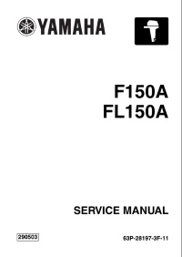
F150A FL150A SERVICE MANUAL 290503 63P-28197-3F-11… -
Page 2: Important Information
NOTICE This manual has been prepared by Yamaha primarily for use by Yamaha dealers and their trained mechanics when performing maintenance procedures and repairs to Yamaha equipment. It has been written to suit the needs of persons who have a basic understanding of the mechanical and electrical concepts and procedures inherent in the work, for without such knowledge attempted repairs or service to the equipment could render it unsafe or unfit for use.
-
Page 3: Gen Info
Contents General information INFO Specifications SPEC Periodic checks and adjustments Fuel system FUEL Power unit POWR Lower unit LOWR Bracket unit BRKT – Electrical systems ELEC Troubleshooting TRBL SHTG Index…
-
Page 4: Table Of Contents
INFO General information How to use this manual …………….. 1-1 Manual format……………….. 1-1 Symbols………………… 1-2 Safety while working………………1-3 Fire prevention………………. 1-3 Ventilation………………..1-3 Self-protection ………………. 1-3 Parts, lubricants, and sealants …………..1-3 Good working practices …………….1-4 Disassembly and assembly …………… 1-4 Identification………………..1-5 Applicable models ………………1-5 Serial number ………………..
-
Page 5
Predelivery checks ………………1-22 Checking the fuel system …………….1-22 Checking the gear oil level …………..1-22 Checking the engine oil level…………..1-22 Checking the battery…………….1-22 Checking the outboard motor mounting height……..1-23 Checking the remote control cables …………1-23 Checking the steering system …………..1-24 Checking the gear shift and throttle operation………1-24 Checking the power trim and tilt system………. -
Page 6: How To Use This Manual
INFO General information How to use this manual Manual format The format of this manual has been designed to make service procedures clear and easy to under- stand. Use the information below as a guide for effective and quality service. 1 Parts are shown and detailed in an exploded diagram and are listed in the components list.
-
Page 7: Symbols
7 Apply Yamaha 4-stroke motor oil A Apply corrosion resistant grease 8 Apply gear oil (Yamaha grease D) 9 Apply water resistant grease (Yamaha grease A) B Apply low temperature resistant grease 0 Apply molybdenum disulfide grease (Yamaha grease C)
-
Page 8: Safety While Working
Parts, lubricants, and sealants Use only genuine Yamaha parts, lubricants, and sealants or those recommended by Yamaha, when servicing or repairing the out- board motor. Ventilation Gasoline vapor and exhaust gas are heavier than air and extremely poisonous.
-
Page 9: Good Working Practices
Safety while working Disassembly and assembly 6. Keep a supply of clean, lint-free cloths for wiping up spills, etc. 1. Use compressed air to remove dust and dirt during disassembly. Good working practices Special service tools 2. Apply engine oil to the contact surfaces Use the recommended special service tools of moving parts before assembly.
-
Page 10: Identification
INFO General information Identification Applicable models This manual covers the following models. Applicable models F150AET, FL150AET Serial number outboard motor serial number stamped on a label attached to the port clamp bracket. 1 Model name 2 Approved model code 3 Transom height 4 Serial number Approved Starting…
-
Page 11: Features And Benefits
Identification / Features and benefits Features and benefits Crankshaft and cylinder The center of the crankshaft is offset 10 mm (0.39 in) from the center of the cylinder to make more space to incorporate the throttle body assembly. This design produces good engine balance and allows a compact design. Exhaust gas from each cylinder flows directly into the exhaust manifold to obtain a compact design for the exhaust system.
-
Page 12: Balancer
INFO General information Balancer A two-piece balancer is used in the crankcase to reduce the secondary forces of inertia produced by reciprocating pistons. The balancer shaft 1 is driven by the gear on the crankshaft. The balancer shaft 2 is driven by the gear on the balancer shaft 1. The two counterrotating balancer shafts rotate at twice the speed of the crankshaft and reduce the forces of inertia of the connecting rods and each balancer shaft.
-
Page 13: Connecting Rod
Features and benefits Connecting rod A direction mark for installing the connecting rod to the crankshaft in the proper direction is on the connecting rod cap. The direction mark should face the flywheel. The connecting rod and connecting rod cap are manufactured as a single piece. Then, they are split using impact force.
-
Page 14: Intake System
INFO General information Intake system Multi-point, group fuel injection with four separate throttle valves is adopted for the intake system. Intake air volume is calculated according to engine speed, Intake air pressure, and throttle position, and then the fuel injection volume is determined by the intake air volume to obtain a precise air and fuel ratio under all operating conditions.
-
Page 15: Top Cowling
Features and benefits The shape of the fuel injectors is the same for the F115, F150, F200 and F225. Therefore, each fuel injector is identified by color because the specifications of each fuel injector are different. È É Ê Ë F115 Ì…
-
Page 16: 64E Type Power Trim And Tilt Unit
The 64E type clamp bracket and power trim and tilt unit used for current V4 and V6 outboard motors have been adopted. This allows easier interchanging of Yamaha outboards with the same classification because the mounting dimensions are the same.
-
Page 17: Cooling System
Features and benefits Cooling system The cooling water flow diagram is as follows. To cool the propeller damper, the cooling system is designed so that fresh cooling water is taken in from the front of the trim tab and supplied to the exhaust passage of the lower case to cool the exhaust gas.
-
Page 18: Lubrication System
INFO General information Lubrication system The lubrication oil flow diagram is as follows. Crankcase Cylinder head Cylinder sleeve Camshaft Piston Balancer Crankpin journal IN/EX valve Camshaft journal Crankshaft main journal Main passage Oil filter Oil pressure sensor Oil filter bracket Relief valve Oil pump Oil strainer…
-
Page 19
Features and benefits A dual oil drain system is adopted. An oil drain bolt is located on the bottom of the oil pan. A long dipstick guide, which reaches the bottom of the oil pan, can also be used to pump out the oil completely with an oil-extracting tool. -
Page 20: Fuel System
INFO General information Fuel system A fuel pressure regulator is incorporated onto the outlet of the electric fuel pump to obtain a compact design and simple fuel delivery. Fuel discharged from the pressure regulator returns to the vapor separator after being cooled in the fuel cooler.
-
Page 21: Rectifier Regulator
Features and benefits Rectifier Regulator A water-cooled Rectifier Regulator is incorporated onto the exhaust outer cover. This allows for a compact engine design and produces a large electric current output for charging the battery under low engine speed. S63P1210 È Charging current (A) É…
-
Page 22: Technical Tips
The self-diagnostic function is incorporated into the ECM, and can quickly detect a malfunction when a personal computer is used with the optional software installed. (Refer to the “Yamaha Diag- nostic System Instruction Manual”.) È…
-
Page 23: Fail-Safe Control
Technical tips Fail-safe control If the electrical components malfunction, the ECM controls the ignition and fuel injection as shown in the table. Malfunctioning item Details Ignition control Fuel control No signal received during Pulser coil four consecutive crankshaft Fixed to BTDC 10° Fixed to BTDC 10°…
-
Page 24: Warning Control
INFO General information Warning control This outboard motor is equipped with warning control functions to avoid serious engine damage. The engine speed is limited to approximately 2,000 r/min if the engine overheats, if the oil pressure is low, or if a dual engine system (DES) is operated. When a switch turns on, the engine speed is controlled as shown in the table.
-
Page 25: Shift Cut Control
Technical tips Shift cut control This outboard motor is equipped with a shift cut control system for easier shifting. This device misfires and retards the ignition of some cylinders to fluctuate the engine speed instantly when the engine is running from 400 to 2,000 r/min. This allows smooth engagement and/or disengagement of the dog clutch.
-
Page 26: Propeller Selection
INFO General information Propeller selection Regular rotation model The performance of a boat and outboard Propeller size (in) Material motor will be critically affected by the size 13 1/2 × 23 — M and type of propeller you choose. Propellers 13 3/4 ×…
-
Page 27: Predelivery Checks
Propeller selection / Predelivery checks Predelivery checks Checking the engine oil level 1. Check the engine oil level. To make the delivery process smooth and efficient, the predelivery checks should be completed as explained below. Checking the fuel system 1. Check that the fuel hoses are securely connected and that the fuel tank is full with fuel.
-
Page 28: Checking The Outboard Motor Mounting Height
INFO General information Checking the outboard motor mounting height 1. Check that the anti-cavitation plate is aligned with the bottom of the boat. If the mounting height is too high, cavitation will occur and propulsion will be reduced. Also, the engine speed will increase abnormally and cause the engine to overheat.
-
Page 29: Checking The Steering System
Predelivery checks Checking the steering system Checking the power trim and tilt 1. Check the steering friction for proper system adjustment. 1. Check that the outboard motor tilts up and down smoothly when operating the 2. Check that steering operates power trim and tilt unit.
-
Page 30: Checking The Cooling Water Pilot Hole
INFO General information Checking the cooling water pilot hole 1. Check that cooling water is discharged from the cooling water pilot hole. È S69J1240 È Hour After test run 1. Check for water in the gear oil. 2. Check for fuel leakage in the cowling. Test run 1.
-
Page 31
SPEC Specifications General specifications………………. 2-1 Maintenance specification …………….2-3 Power unit………………..2-3 Lower unit ………………..2-6 Electrical ………………..2-7 Dimensions………………..2-9 Tightening torques………………2-11 Specified torques………………2-11 General torques………………2-13 63P3F11… -
Page 32: General Specifications
SPEC Specifications General specifications Model Item Unit F150AET FL150AET Dimension Overall length mm (in) 822 (32.4) Overall width mm (in) 511 (20.1) Overall height mm (in) 1,714 (67.5) mm (in) 1,842 (72.5) Boat transom height mm (in) 508 (20.0) mm (in) 635 (25.0) Weight (with aluminium propeller)
-
Page 33
General specifications Model Item Unit F150AET FL150AET Fuel and oil Fuel type Regular unleaded gasoline (*1) Fuel minimum rating Engine oil 4-stroke motor oil Engine oil grade SE, SF, SG, SH, or SJ 10W-30 or 10W-40 Engine oil quantity (without oil filter replacement) L (US qt, 5.2 (5.5, 4.6) lmp qt) -
Page 34: Specifications
SPEC Specifications Maintenance specification Power unit Model Item Unit F150AET FL150AET Power unit Minimum compression 880 (8.8, 128) (*1) pressure (kgf/cm , psi) (*2) Lubrication oil pressure 450 (4.5, 65.3) at engine idle speed (kgf/cm , psi) Cylinder head Warpage limit mm (in) 0.10 (0.0039) (lines indicate straightedge…
-
Page 35
Maintenance specification Model Item Unit F150AET FL150AET Oil ring Dimension B mm (in) 2.40–2.47 (0.0945–0.0972) Dimension T mm (in) 2.30–2.70 (0.0906–0.1063) End gap mm (in) 0.15–0.60 (0.0059–0.0236) Side clearance mm (in) 0.04–0.13 (0.0016–0.0051) Camshafts Intake (A) mm (in) 45.300–45.400 (1.7835–1.7874) Exhaust (A) mm (in) 44.350–44.450 (1.7461–1.7500) -
Page 36
SPEC Specifications Model Item Unit F150AET FL150AET Valve lifters Valve lifter outside diameter mm (in) 32.982–32.997 (1.2985–1.2990) Valve lifter-to-cylinder head mm (in) 0.020–0.055 (0.0008–0.0022) clearance Valve shims Valve shim thickness mm (in) 2.3–2.9 (0.09–0.12) (in 0.020 mm increments) Connecting rods Big-end inside diameter mm (in) 53.025–53.045 (2.0876–2.0884) -
Page 37: Lower Unit
Maintenance specification Model Item Unit F150AET FL150AET Oil pump Discharge L (US gal, 8.0 (2.113, 1.760) at 700 r/min at 97–103 °C (207–217 °F) lmp gal)/min with 10W-30 engine oil Pressure 132.0–162.0 (1.32–1.62, 19.1–23.5) (kgf/cm , psi) Relief valve opening pressure 392–490 (3.92–4.90, 56.84–71.05) (kgf/cm , psi)
-
Page 38: Electrical
SPEC Specifications Electrical Model Item Unit F150AET FL150AET Ignition and ignition control system Ignition timing (cylinder #1) Degree TDC at engine idle speed Spark plug gap mm (in) 1.0–1.1 (0.039–0.043) Ignition coil resistance Primary coil (R – B/W) Ω at 20 °C (68 °F) 1.53–2.07 Secondary coil at 20 °C (68 °F)
-
Page 39
Maintenance specification Model Item Unit F150AET FL150AET Starter motor Type Sliding gear Output 1.40 Cranking time limit Second Brushes Standard length mm (in) 15.5 (0.61) Wear limit mm (in) 9.5 (0.37) Commutator Standard diameter mm (in) 29.0 (1.14) Wear limit mm (in) 28.0 (1.10) Mica… -
Page 40: Dimensions
SPEC Specifications Dimensions Exterior mm (in) L: 1,032 (40.7) 629 (24.8) X: 1,148 (45.2) 164 (6.5) 698 (27.5) 75 (3.0) 162(6.4) L: 35 (1.4) X: 43 (1.7) 646 (25.4) S63P2010 63P3F11…
-
Page 41
Maintenance specification Clamp bracket mm (in) 180 (7.1) 180 (7.1) 163.5 (6.4) 163.5 (6.4) 82 (3.2) 13 (0.5) 13 (0.5) 125.4 (4.9) 125.4 (4.9) S63P2020 2-10 63P3F11… -
Page 42: Tightening Torques
SPEC Specifications Tightening torques Specified torques Tightening torques Part to be tightened Thread size N·m kgf·m ft·lb Fuel system Fuel filter holder bolt Fuel filter bracket bolt Fuel pump mounting bolt Fuel pump screw ø6 Fuel cooler bolt Vapor separator mounting bolt Fuel rail mounting bolt Throttle body mounting bolt Power unit…
-
Page 43
Tightening torques Tightening torques Part to be tightened Thread size N·m kgf·m ft·lb Exhaust cover bolt Thermostat cover bolt 17.0 Exhaust cover plug 40.6 Oil filter union bolt — 25.1 Balancer bolt 13.3 22.9 Oil pump screw — 10.3 19.2 Crankcase bolt 22.1 90°… -
Page 44
SPEC Specifications Tightening torques Part to be tightened Thread size N·m kgf·m ft·lb 14.8 Muffler assembly bolt 31.0 Engine oil drain bolt 20.0 Baffle plate screw ø5 Muffler bolt 14.8 Exhaust manifold bolt 14.8 Oil pan bolt 14.8 Oil strainer bolt Upper mounting nut (M14) 54.6… -
Page 45
Periodic checks and adjustments Special service tools ………………3-1 Maintenance interval chart…………….3-2 Top cowling ………………..3-3 Checking the top cowling…………….3-3 Fuel system ………………..3-3 Checking the fuel joint and fuel hoses (fuel joint-to-fuel injector) ….3-3 Checking the fuel filter …………….3-3 Power unit………………….. -
Page 46: Chk Adj
Periodic checks and adjustments Special service tools Oil filter wrench 90890-06830 Digital tachometer 90890-06760 Timing light 90890-03141 Leakage tester 90890-06840 63P3F11…
-
Page 47: Maintenance Interval Chart
Special service tools / Maintenance interval chart Maintenance interval chart Use the following chart as a guideline for general maintenance. Adjust the maintenance intervals according to the operating conditions of the outboard motor. Initial Every Refer to Item Remarks 10 hours 50 hours 100 hours 200 hours…
-
Page 48: Top Cowling
Periodic checks and adjustments Top cowling Checking the top cowling 1. Check the fitting by pushing the cowling with both hands. Adjust if necessary. S63P3030 Fuel system Checking the fuel joint and fuel hoses (fuel joint-to-fuel injector) 1. Remove the spark plug wire cover. 2.
-
Page 49: Power Unit
Top cowling / Fuel system / Power unit Changing the engine oil using an oil changer 1. Start the engine, warm it up, and then turn it off. 2. Remove the engine oil dipstick and oil filler cap 1. NOTE: Be sure not to spill any fuel when removing the fuel filter cup.
-
Page 50: Changing The Engine Oil By Draining It
Periodic checks and adjustments 6. Install the oil filler cap and dipstick, and Recommended engine oil: then start the engine and warm it up for 5 4-stroke motor oil minutes. API: SE, SF, SG, SH, or SJ 7. Turn the engine off, and then check the SAE: 10W-30 or 10W-40 oil level and correct it if necessary.
-
Page 51: Checking The Timing Belt
Power unit S63P3040 Replacing the timing belt NOTE: S63P3100 For replacement procedures, see Chapter 5, “Replacing the timing belt.” Oil filter: 18 N·m (1.8 kgf·m, 13.3 ft·lb) Checking the valve clearance 5. Pour the specified amount of the recom- mended engine oil into the oil filler hole. NOTE: For checking procedures, see Chapter 5, Recommended engine oil:…
-
Page 52: Checking The Thermostat
Periodic checks and adjustments 4. Check the spark plug gap a. Adjust if out 3. Suspend the thermostat in a container of of specification. water. 4. Place a thermometer in the water and slowly heat the water. Specified spark plug: LFR5A-11 (NGK) S69J5E40 Spark plug gap a:…
-
Page 53: Checking The Cooling Water Passage
Power unit / Control system Checking the cooling water passage 1. Check the cooling water inlet cover 1 and cooling water inlet for clogs. Clean if necessary. S63P3140 Digital tachometer: 90890-06760 Engine idle speed: 700 ± 50 r/min Adjusting the throttle link and throttle cable NOTE: S60V3130…
-
Page 54
Periodic checks and adjustments 4. Turn throttle lever 1 7 and the throttle cam 8 counterclockwise so that they are in the positions shown in the illustration. S63P3160 S63P3180 5. Check that the throttle valves are fully NOTE: closed, and then adjust the throttle link If there is no clearance, loosen the locknut 4 rod joint to align its hole with the ball joint 9 on throttle lever 1. -
Page 55: Adjusting The Throttle Link And Throttle Cable Operation (Using A Thickness Gauge)
Control system 10. Contact the stopper 0 on the throttle Adjusting the throttle link and lever 2 to the fully closed stopper A on throttle cable operation the cylinder block and check that throttle (using a thickness gauge) cam roller B is aligned with the align- 1.
-
Page 56: Checking The Gear Shift Operation
Periodic checks and adjustments 5. Operate throttle lever 2 to check that the throttle valves fully close and fully open. S63P3210 CAUTION: S63P3240 The throttle cable joint must be screwed NOTE: in a minimum of 8.0 mm (0.31 in) d. The throttle valves are fully open when the throttle cam roller 8 is within the range b shown in the illustration.
-
Page 57: Checking The Ignition Timing
Control system S63P3270 S63P3140 6. Adjust the position of the shift cable joint Digital tachometer: 90890-06760 until its hole is aligned with the set pin. 3. Attach the special service tool to spark plug wire #1. S69J3370 CAUTION: The shift cable joint must be screwed in a S63P3280 minimum of 8.0 mm (0.31 in) c.
-
Page 58: Power Trim And Tilt Unit
Periodic checks and adjustments Power trim and tilt unit WARNING Checking the power trim and tilt After tilting up the outboard motor, be operation sure to support it with the tilt stop lever. 1. Fully tilt the outboard motor up and down Otherwise, the outboard motor could sud- a few times and check the entire trim and denly lower if the power trim and tilt unit…
-
Page 59: Changing The Gear Oil
Power trim and tilt unit / Lower unit 3. Check the oil for metal and discoloration, and its viscosity. Check the internal parts of the lower case if necessary. 4. Insert a gear oil tube or gear oil pump into the drain hole and slowly fill the gear oil until oil flows out of the check hole and no air bubbles are visible.
-
Page 60: Checking The Lower Unit For Air Leakage
Periodic checks and adjustments Checking the lower unit for air leakage 1. Remove the check screw 1, and then install the special service tool. S69J3580 General Checking the anodes 1. Check the anodes and trim tab for scales, grease, or oil. Clean if necessary. Leakage tester: 90890-06840 2.
-
Page 61: Checking The Battery
Lower unit / General Batteries generate explosive, hydrogen CAUTION: gas. Always follow these preventive mea- sures: Do not oil, grease, or paint the anodes or • Charge batteries in a well-ventilated the trim tab, otherwise they will be ineffec- tive. area.
-
Page 62
Periodic checks and adjustments NOTE: Apply grease to the grease nipple until it flows from the bushings a. 2. Apply low temperature resistant grease to the areas shown. S63P3320 S63P3340 3. Apply corrosion resistant grease to the S60X3090 areas shown. S60X3100 S60X3120 3-17… -
Page 63
FUEL Fuel system Special service tools ………………4-1 Hose routing ………………..4-2 Fuel and blowby hoses…………….4-2 Fuel filter, fuel pump, and intake silencer ……….. 4-3 Checking the fuel pumps …………….4-7 Disassembling a fuel pump …………… 4-7 Checking the diaphragm and valves …………4-8 Assembling a fuel pump …………….4-8 Intake assembly and vapor separator………… -
Page 64: Fuel System
FUEL Fuel system Special service tools Vacuum/pressure pump gauge set Test harness (3 pins) 90890-06756 90890-06793 Fuel pressure gauge 90890-06786 Digital circuit tester 90890-03174 Vacuum gauge 90890-03159 Digital tachometer 90890-06760 63P3F11…
-
Page 65: Hose Routing
Special service tools / Hose routing Hose routing Fuel and blowby hoses 1 Blowby hoses 2 Fuel hose (fuel tank-to-fuel filter) 3 Fuel hoses (fuel filter-to-fuel pumps) 4 Fuel hoses (fuel pumps-to-fuel filter) 5 Fuel hose (fuel filter-to-vapor separator) 6 High-pressure fuel hose (vapor separator-to-fuel rail) 7 Fuel hose (pressure regulator-to-fuel cooler) 8 Fuel hose (fuel cooler-to-vapor separator) 63P3F11…
-
Page 66: Fuel Filter, Fuel Pump, And Intake Silencer
FUEL Fuel system Fuel filter, fuel pump, and intake silencer 14 13 · · · 10 N m (1.0 kgf m, 7.4 ft S63P4070 Part name Q’ty Remarks Intake assembly M8 × 40 mm Bolt M8 × 20 mm Bolt Intake silencer M6 ×…
-
Page 67
Fuel filter, fuel pump, and intake silencer S63P4080 Part name Q’ty Remarks Throttle lever 1 Throttle cam Throttle lever 2 Throttle link rod M6 × 35 mm Bolt M6 × 25 mm Bolt Collar Wave washer Washer Spring 63P3F11… -
Page 68
FUEL Fuel system · · · m (0.8 kgf m, 5.9 ft · · · m (0.8 kgf m, 5.9 ft S63P4040 Part name Q’ty Remarks M6 × 14 mm Bolt Bracket M6 × 16 mm Bolt Washer Holder O-ring Not reusable Fuel filter element Float… -
Page 69
Fuel filter, fuel pump, and intake silencer · · · m (0.4 kgf m, 3.0 ft 13 14 S63P4050 Part name Q’ty Remarks ø6 × 35 mm Screw Cover Fuel pump body 2 Fuel pump body 1 Plunger Spring Spring Diaphragm Spring Valve… -
Page 70: Checking The Fuel Pumps
FUEL Fuel system Checking the fuel pumps 6. Apply the specified positive pressure and check that there is no air leakage. Disas- 1. Place a drain pan under the fuel hose semble the fuel pump if necessary. connections, and then disconnect the fuel hoses from the fuel pumps.
-
Page 71: Checking The Diaphragm And Valves
Fuel filter, fuel pump, and intake silencer Assembling a fuel pump 2. Push down on the plunger and the dia- phragm, turn fuel pump body 1 1 NOTE: approximately 90° to a position where the Clean the parts and soak the valves and the pin 2 can be removed easily, and then diaphragm in gasoline before assembly to remove the pin.
-
Page 72: Intake Assembly And Vapor Separator
FUEL Fuel system Intake assembly and vapor separator · · · m (0.5 kgf m, 3.7 ft · · · m (0.5 kgf m, 3.7 ft S63P4010 Part name Q’ty Remarks M6 × 25 mm Bolt Fuel cooler Vapor separator Fuel hose Fuel hose Hose…
-
Page 73
Intake assembly and vapor separator S63P4030 Part name Q’ty Remarks O-ring Not reusable Float chamber Drain screw Pressure regulator M6 × 12 mm Screw O-ring Not reusable Cover ø4 × 16 mm Screw Electric fuel pump Filter Filter holder O-ring Not reusable Collar Needle valve… -
Page 74
FUEL Fuel system · · · 13 N m (1.3 kgf m, 9.6 ft · · · 13 N m (1.3 kgf m, 9.6 ft S63P4020 Part name Q’ty Remarks Fuel rail M8 × 25 mm Bolt O-ring Not reusable Rubber damper Not reusable Fuel injector… -
Page 75
Intake assembly and vapor separator · · · 13 N m (1.3 kgf m, 9.6 ft · · · 13 N m (1.3 kgf m, 9.6 ft S63P4020 Part name Q’ty Remarks Collar Grommet Bracket ø6 × 16 mm Screw ø4 ×… -
Page 76: Measuring The Fuel Pressure
FUEL Fuel system Measuring the fuel pressure WARNING 1. Remove the cap 1. • Before measuring the fuel pressure, 2. Connect the fuel pressure gauge to the make sure that the drain screw is tight- pressure check valve. ened securely. •…
-
Page 77: Checking The Check Valve
Intake assembly and vapor separator WARNING • When connecting the fuel pressure gauge, first cover connection between the gauge and the pressure check valve with a clean, dry rag to pre- vent fuel from leaking out. • Gently screw in the gauge until it is firmly connected.
-
Page 78: Reducing The Fuel Pressure
FUEL Fuel system Reducing the fuel pressure Checking the vapor separator 1. Remove the cap 1. 1. Check the needle valve for bends or wear. Replace if necessary. 2. Cover the pressure check valve a of the fuel rail with a rag, and then press in the pressure check valve a using a thin screwdriver to release the fuel pressure.
-
Page 79: Synchronizing The Throttle Valves
Intake assembly and vapor separator Synchronizing the throttle valves NOTE: For best results, use a vacuum gauge (com- CAUTION: mercially available), like 2 or 3 shown in the Do not adjust the throttle valve when it is illustration, that has four adapters. operating properly.
-
Page 80: Adjusting The Throttle Position Sensor
FUEL Fuel system 5. Turn the synchronizing screw 5 so that 1. Remove the intake silencer. the vacuum pressure of cylinder #3 or #4 2. Disconnect the throttle joint link rod 1 is within 4 kPa (30 mmHg) based on the from the throttle lever 1.
-
Page 81: Adjusting The Throttle Position Sensor (When Disassembling Or Replacing The Throttle Body)
Intake assembly and vapor separator NOTE: To measure the output voltage, connect the positive tester probe to the pink wire of the test harness and the negative tester probe to the orange wire of the test harness. Digital circuit tester: 90890-03174 S63P4280 4.
-
Page 82
FUEL Fuel system 12. Install the throttle joint link rod 3 so the throttle cam roller 4 is aligned with the alignment mark a as shown. S63P4290 NOTE: Make sure that the throttle position sensor output voltage does not change when install- ing the throttle joint link rod. -
Page 83
Intake assembly and vapor separator — MEMO — 4-20 63P3F11… -
Page 84
POWR Power unit Special service tools ………………5-1 Power unit………………….. 5-3 Checking the compression pressure …………5-11 Checking the oil pressure …………….5-11 Checking the oil pressure sensor …………5-12 Checking the valve clearance…………..5-12 Replacing the timing belt ……………..5-16 Removing the power unit……………..5-18 Removing the oil filter ……………. -
Page 85
Cylinder block ………………..5-38 Disassembling the cylinder block …………5-41 Checking the balancer assembly…………. 5-41 Checking the piston diameter …………..5-41 Checking the cylinder bore …………..5-42 Checking the piston clearance …………..5-42 Checking the piston rings …………….5-42 Checking the piston ring grooves …………5-43 Checking the piston ring side clearance………. -
Page 86: Power Unit
POWR Power unit Special service tools Compression gauge Flywheel puller 90890-03160 90890-06521 Compression gauge extension Valve spring compressor 90890-06563 90890-04019 Test harness (3 pins) Valve spring compressor attachment New: 90890-06869 90890-06320 Current: 90890-06769 Valve guide remover/installer Flywheel holder 90890-06801 90890-06522 Valve guide installer Oil filter wrench 90890-06810…
-
Page 87
Special service tools Valve guide reamer Piston ring compressor 90890-06804 90890-05158 Valve seat cutter holder 90890-06316 Valve seat cutter 90890-06324, 90890-06325, 90890-06326, 90890-06327 Needle bearing attachment 90890-06611, 90890-06654 Driver rod L3 90890-06652 63P3F11… -
Page 88: Power Unit
POWR Power unit Power unit · · · m (0.8 kgf m, 5.9 ft · · · 42 N m (4.2 kgf m, 31.0 ft · · · 20 N m (2.0 kgf m, 14.8 ft · · · m (0.4 kgf m, 3.0 ft S63P5560 Part name…
-
Page 89
Power unit Part name Q’ty Remarks Washer Flywheel magnet M6 × 35 mm Bolt Holder Bracket Collar Holder Stator coil bracket Hose Plastic tie Not reusable Woodruff key Stator coil ø6 × 30 mm Screw 63P3F11… -
Page 90
POWR Power unit · · · 29 N m (2.9 kgf m, 21.4 ft · · · m (0.9 kgf m, 6.6 ft · · · m (0.7 kgf m, 5.2 ft · · · 18 N m (1.8 kgf m, 13.3 ft ·… -
Page 91
Power unit S63P5600 Part name Q’ty Remarks Grommet Fuse holder Terminal plate Terminal Terminal Fuse holder Fuse 50 A ø5 × 10 mm Screw Fuse 20 A Relay Fuse 30 A ø3 × 10 mm Screw ø5 × 20 mm Screw 63P3F11… -
Page 92
POWR Power unit · · · m (0.4 kgf m, 3.0 ft S63P5610 Part name Q’ty Remarks Junction box M6 × 16 mm Bolt Wiring harness M6 × 20 mm Bolt Washer Power trim and tilt relay M6 × 20 mm Bolt Starter relay Holder… -
Page 93
Power unit · · · m (0.4 kgf m, 3.0 ft S63P5610 Part name Q’ty Remarks Holder M6 × 12 mm Bolt Intake air temperature sensor Grommet ø6 × 19 mm Screw Bracket ø6 × 19 mm Screw Holder Collar Grommet M6 ×… -
Page 94
POWR Power unit Part name Q’ty Remarks Timing belt Timing belt tensioner M5 × 40 mm Bolt Drive sprocket Plate Woodruff key M10 × 35 mm Bolt Driven sprocket Oil seal Dowel Camshaft Camshaft Camshaft cap Camshaft cap M7 × 48 mm Bolt M7 ×… -
Page 95
Power unit Part name Q’ty Remarks ø4 × 8 mm Screw Plate Grommet Cylinder head cover M6 × 30 mm Bolt Holder M6 × 10 mm Bolt Clamp Hose Dowel Dowel 5-10 63P3F11… -
Page 96: Checking The Compression Pressure
POWR Power unit Checking the compression pressure NOTE: 1. Start the engine, warm it up for 5 min- • If the compression pressure increases, utes, and then turn it off. check the pistons and piston rings for wear. Replace if necessary. 2.
-
Page 97: Checking The Oil Pressure Sensor
Power unit Checking the oil pressure sensor Checking the valve clearance 1. Connect the test harness (3 pins) to the 1. Remove the flywheel magnet cover and oil pressure sensor. spark plug wire cover. 2. Start the engine and warm it up for 5 min- 2.
-
Page 98
POWR Power unit 5. Check the intake valve clearance for cyl- 9. Using a hexagon wrench, turn the timing belt tensioner 4 clockwise to push the inders #1 and #2, and exhaust valve clearance for cylinders #1 and #3. Adjust timing belt, increase strength gradually, and then insert a ø5.0 mm (0.2 in) pin 5 if out of specification. -
Page 99
Power unit 17. Install the necessary valve shim into the valve lifter. 18. Install the camshafts into the cylinder head with new oil seals. 63P IN S63P5100 63P EX 13. Remove the camshafts. 14. Remove the valve shim 7 from the valve lifter 8 using compressed air. -
Page 100
POWR Power unit 21. Check that “I” marks c and d on the 19. Install the camshaft caps, and then tighten them to the specified torques in driven sprockets are aligned. Adjust if two stages and in the sequence shown in necessary. -
Page 101: Replacing The Timing Belt
Power unit NOTE: Do not turn the flywheel magnet counter- clockwise. 24. Check the valve clearances. Adjust if necessary. 25. Install the spark plugs, and then tighten them to the specified torque. 26. Install the cylinder head cover bolts, and then tighten them to the specified torques in two stages.
-
Page 102
POWR Power unit 4. Remove the flywheel magnet. 6. Using a hexagon wrench, turn the timing belt tensioner 5 clockwise to push the timing belt, increase strength gradually, and then insert a ø5.0 mm (0.2 in) pin 6 into the hole e. NOTE: Leave the pin inserted into the timing belt tensioner until the timing belt has been… -
Page 103: Removing The Power Unit
Power unit 9. Install a new timing belt 7 from the drive sprocket side with its part number in the upright position, turn the belt a half turn counterclockwise to align it, and then remove the pin 6. 13. Install the flywheel magnet. S63P5330 CAUTION: Apply force in the direction of the arrows…
-
Page 104
POWR Power unit 2. Disconnect the battery leads 1. S63P5420 S63P5380 7. Disconnect the PTT switch coupler, shift 3. Disconnect the throttle cable 2 and shift cut switch coupler, neutral switch cou- cable 3. pler, cooling water pilot hose, and flush- ing hose. -
Page 105: Removing The Oil Filter
Power unit NOTE: Be sure to clean up any oil spills. Oil filter wrench: 90890-06830 Removing the timing belt and sprockets 1. Turn the drive sprocket clockwise and align the “ ” mark a on the plate with the “I” mark b on the cylinder block, and check that “I”…
-
Page 106: Checking The Timing Belt And Sprockets
POWR Power unit 2. Using a hexagon wrench, turn the timing Checking the timing belt and belt tensioner 1 clockwise to push the sprockets timing belt, increase strength gradually, 1. Check the interior and exterior of the tim- and then insert a ø5.0 mm (0.2 in) pin 2 ing belt for cracks, damage, or wear.
-
Page 107
Power unit Drive sprocket bolt: 7 N·m (0.7 kgf·m, 5.2 ft·lb) Timing belt tensioner bolt: 39 N·m (3.9 kgf·m, 28.8 ft·lb) 6. Install the timing belt 5 from the drive sprocket side with its part number in the S1280B upright position, turn the belt a half turn counterclockwise to align it, and then remove the pin 6. -
Page 108: Cylinder Head
POWR Power unit Cylinder head Part name Q’ty Remarks M8 × 55 mm Bolt Valve shim Valve lifter Valve cotter Valve spring retainer Valve spring Valve seal Not reusable Valve guide Not reusable M10 × 120 mm Bolt Spark plug M8 ×…
-
Page 109
Cylinder head Part name Q’ty Remarks Intake valve Gasket Not reusable Collar Anode ø6 × 16 mm Screw Anode 5-24 63P3F11… -
Page 110
POWR Power unit · · · 23 N m (2.3 kgf m, 17.0 ft · · · 12 N m (1.2 kgf m, 8.9 ft · · · m (0.6 kgf m, 4.4 ft · · · 12 N m (1.2 kgf m, 8.9 ft ·… -
Page 111
Cylinder head · · · 23 N m (2.3 kgf m, 17.0 ft · · · 12 N m (1.2 kgf m, 8.9 ft · · · m (0.6 kgf m, 4.4 ft · · · 12 N m (1.2 kgf m, 8.9 ft ·… -
Page 112
POWR Power unit · · · 23 N m (2.3 kgf m, 17.0 ft · · · 12 N m (1.2 kgf m, 8.9 ft · · · m (0.6 kgf m, 4.4 ft · · · 12 N m (1.2 kgf m, 8.9 ft ·… -
Page 113: Removing The Cylinder Head
Cylinder head Removing the cylinder head 4. Remove the intake valve and exhaust valves. 1. Remove the camshaft caps in the sequence shown. S63P5100 2. Remove the camshafts and cylinder head bolts in the sequence shown. NOTE: Be sure to keep the valves, springs, and other parts in the order as they were removed.
-
Page 114: Checking The Valves
POWR Power unit 2. Measure the valve spring tilt b. Replace Valve stem diameter b: if out of specification. Intake: 5.477–5.492 mm (0.2156–0.2162 in) Exhaust: 5.464–5.479 mm (0.2151–0.2157 in) 4. Measure the valve stem runout. Replace if out of specification. Valve spring tilt limit b: 1.5 mm (0.06 in) Checking the valves…
-
Page 115: Replacing The Valve Guides
Cylinder head 2. Calculate the valve stem-to-valve guide Valve guide remover/installer: clearance as follows. Replace the valve 90890-06801 guide if out of specification. Valve guide installer: 90890-06810 Valve stem-to-valve guide clearance = valve guide inside diameter – valve 3. Insert the special service tool into the valve guide 2, and then ream the valve stem diameter: Intake and exhaust:…
-
Page 116: Checking The Valve Seat
POWR Power unit Checking the valve seat 1. Eliminate carbon deposits from the valve with a scraper. 2. Apply a thin, even layer of Mechanic’s blueing dye (Dykem) onto the valve seat. 3. Lap the valve slowly on the valve seat with a valve lapper (commercially avail- able) as shown.
-
Page 117
Cylinder head 60˚ S69J5890 S63P5240 b Previous contact width 5. Use a 45° cutter to adjust the contact width of the valve seat to specification. a Slag or rough surface 45˚ CAUTION: S69J5900 Do not over cut the valve seat. Be sure to b Previous contact width turn the cutter evenly downward at a pres- c Specified contact width… -
Page 118: Checking The Camshaft
POWR Power unit 7. If the valve seat contact area is too nar- CAUTION: row and situated near the top edge of the valve face, use a 30° cutter to cut the top Do not get the lapping compound on the edge of the valve seat.
-
Page 119: Checking The Cylinder Head
Cylinder head Checking the cylinder head 1. Eliminate carbon deposits from the com- bustion chambers and check for deterio- ration. 2. Check the cylinder head warpage using a straightedge 1 and thickness gauge 2 in seven directions as shown. Replace if out of specification.
-
Page 120: Installing The Cylinder Head
POWR Power unit 2. Install the valve 2, valve spring 3, and valve spring retainer 4 in the sequence shown, and then attach the special ser- vice tool. S63P5210 NOTE: Apply engine oil to the valve shims and valve lifters before installation. Installing the cylinder head 1.
-
Page 121
Cylinder head 3. Install the camshaft caps, and then NOTE: tighten the bolts to the specified torques • Apply engine oil to the cylinder head bolts in two stages and in the sequence before installation. shown. • Tighten the M10 bolts to the specified torques in two stages first, and then make a mark a on the M10 bolts and the cylinder head, and then tighten the bolts 90°… -
Page 122: Removing The Exhaust Cover
POWR Power unit Removing the exhaust cover Installing the pressure control valve 1. Remove the cover 1 and thermostat 2. 1. Install a new gasket and the pressure control valve, and then tighten the bolts. S63P3110 S63P5670 2. Remove the exhaust cover bolts in the sequence shown.
-
Page 123: Cylinder Block
Cylinder head / Cylinder block Cylinder block Part name Q’ty Remarks Engine hanger M6 × 20 mm Bolt Oil filler cap O-ring Oil filler neck Gasket Not reusable M6 × 45 mm Bolt Seal Not reusable Balancer assembly M8 × 55 mm Bolt M6 ×…
-
Page 124
POWR Power unit Part name Q’ty Remarks Oil seal Not reusable Oil seal Not reusable M6 × 40 mm Bolt 5-39 63P3F11… -
Page 125
Cylinder block · · · 30 N m (3.0 kgf m, 22.1 ft · · · 30 N m (3.0 kgf m, 22.1 ft 90˚ 90˚ S1280B · · · 14 N m (1.4 kgf m, 10.3 ft · · ·… -
Page 126: Disassembling The Cylinder Block
POWR Power unit Disassembling the cylinder block NOTE: 1. Remove the oil pump. • Be sure to keep the bearings in the order as they were removed. 2. Remove the balancer bolts in the • Mark each piston with an identification sequence shown.
-
Page 127: Checking The Cylinder Bore
Cylinder block 3. Calculate the out-of-round limit. Replace the cylinder block if out of specification. Out-of-round limit: (measuring point a) –D (measuring point c) –D 0.05 mm (0.0020 in) Checking the piston clearance 1. Replace the piston and piston rings as a set, or the cylinder block, or all parts if Piston diameter a: out of specification.
-
Page 128: Checking The Piston Ring Grooves
POWR Power unit 2. Level the piston ring 1 in the cylinder Piston ring groove: with a piston crown. Top ring a: 3. Check the piston ring end gap d at the 1.23–1.25 mm (0.048–0.049 in) Second ring b: specified measuring point. Replace if out of specification.
-
Page 129: Checking The Crankshaft
Cylinder block Crankshaft journal diameter a: 51.980–52.000 mm (2.0465–2.0472 in) Crankpin diameter b: 49.980–50.000 mm Connecting rod big end side clearance a: (1.9677–1.9685 in) Crankpin width c: 0.14–0.31 mm (0.006–0.012 in) 22.00–22.10 mm (0.8661–0.8701 in) Checking the crankshaft 1. Check the teeth of the crankshaft gear 3.
-
Page 130: Checking The Crankpin Oil Clearance
POWR Power unit Checking the crankpin oil clearance 1. Clean the bearings and the connecting rod. 2. Install the upper bearing into the con- necting rod 1 and the lower bearing into the connecting rod cap 2. NOTE: Install the connecting rod bearings in their NOTE: original positions.
-
Page 131: Selecting The Connecting Rod Bearing
Cylinder block Example: Connecting rod bolt: Connecting rod big Numerical value 1st: 23 N·m (2.3 kgf·m, 17.0 ft·lb) end inside diameter a in table 2nd: 43 N·m (4.3 kgf·m, 31.7 ft·lb) 53.035 mm 3rd: 90° 3. Check the crankpin mark b on the 6.
-
Page 132: Checking The Crankshaft Main Journal Oil Clearance
POWR Power unit 4. Select the suitable color c for the con- NOTE: necting rod bearing from the table. • Example: If the connecting rod big end inside diameter a is “35” and the crankpin mark b is “81,” then select the bearing col- ors in “g.”…
-
Page 133: Selecting The Crankshaft Main Bearing
Cylinder block Selecting the crankshaft main bearing 1. When replacing the main bearing, select the suitable bearing as follows. 2. Check the crankshaft journal mark a on the crankshaft and the cylinder block mark b on the cylinder block. NOTE: Do not put the Plastigauge (PG-1) over the oil hole in the main journals of the crankshaft.
-
Page 134: Disassembling The Oil Pump
POWR Power unit 3. Select the suitable color c for the main bearing from the table. S63P5850 Cylinder block mark b Checking the oil pump 1. Check the gear teeth for cracks or wear and the oil pump case for scratches. Replace the oil pump assembly if neces- sary.
-
Page 135: Assembling The Pistons And Cylinder Block
Cylinder block Screw 8: 4 N·m (0.4 kgf·m, 3.0 ft·lb) Assembling the pistons and cylinder block 1. Install the oil ring 1, second ring 2, and top ring 3 onto the pistons with the “RN” mark a of the second ring and the “R” mark a of the top ring facing upward.
-
Page 136
POWR Power unit 3. Install the upper bearing into the con- necting rod 4 and the lower bearing into the connecting rod cap 5. NOTE: Install the connecting rod bearings in their NOTE: original positions. Apply engine oil to the inner oil seal before installation. -
Page 137
Cylinder block NOTE: Apply engine oil to the side of the pistons and piston rings before installation. Piston ring compressor: 90890-05158 9. Install the connecting rod caps 5 to the connecting rods, and then tighten the connecting rod bolts to the specified torques in three stages. -
Page 138
POWR Power unit 10. Install half of the main bearings A into NOTE: the crankcase. • Crankcase bolts 1–4 can be reused three times. 11. Apply sealant to the mating surface of • Apply engine oil to the crankcase bolts the crankcase. -
Page 139
Cylinder block 16. Apply sealant to the mating surface of 18. After installing the balancer assembly the balancer assembly. onto the crankcase, apply sealant around the periphery of the seals C, and then install them onto the balancer assembly. NOTE: Do not get any sealant inside the balancer assembly. -
Page 140: Installing The Power Unit
POWR Power unit 20. Before installing the oil filter, be sure to fill it with engine oil through the oil pas- sage j of the oil filter bracket. S63P5B20 21. Install the oil filter, and then tighten it to the specified torque using a 72.5 mm Exhaust cover bolt: (2.9 in) oil filter wrench.
-
Page 141
Cylinder block 6. Connect the fuel hose 8. S63P5B80 7. Connect the PTT motor leads 9, and then install the junction box cover. S63P5B40 S63P5B90 S63P5B50 Power unit mounting bolt (M8) 4: PTT motor lead bolt: 4 N·m (0.4 kgf·m, 3.0 ft·lb) 20 N·m (2.0 kgf·m, 14.8 ft·lb) Power unit mounting bolt (M10) 5: 8. -
Page 142
POWR Power unit 9. Connect the battery leads B. Flywheel holder: 90890-06522 Flywheel magnet nut: 270 N·m (27.0 kgf·m, 199.1 ft·lb) 13. Install all parts removed during disas- sembly. S63P5C10 Positive battery cable nut: 9 N·m (0.9 kgf·m, 6.6 ft·lb) 10. -
Page 143
Cylinder block — MEMO — 5-58 63P3F11… -
Page 144
LOWR Lower unit Special service tools ………………6-1 Lower unit (regular rotation model) …………. 6-4 Removing the lower unit …………….6-8 Removing the water pump and shift rod………… 6-8 Checking the water pump and shift rod ………….6-9 Propeller shaft housing (regular rotation model) ……..6-10 Removing the propeller shaft housing assembly…….. -
Page 145
Lower unit (counter rotation model) …………6-32 Removing the lower unit …………….6-36 Removing the water pump and shift rod……….6-36 Checking the water pump and shift rod ………..6-37 Propeller shaft housing (counter rotation model) ……..6-38 Removing the propeller shaft housing assembly……..6-40 Disassembling the propeller shaft assembly ………..6-40 Disassembling the forward gear …………..6-40 Disassembling the propeller shaft housing………. -
Page 146: Lower Unit
LOWR Lower unit Special service tools Ring nut wrench 4 Bearing separator 90890-06512 90890-06534 Ring nut wrench extension Stopper guide stand 90890-06513 90890-06538 Bearing housing puller claw L Bearing puller assembly 90890-06502 90890-06535 Stopper guide plate Needle bearing attachment 90890-06501 90890-06610, 90890-06612, 90890-06653, 90890-06654 Center bolt…
-
Page 147
Special service tools Driver rod SS Bearing outer race puller assembly 90890-06604 90890-06523 Bearing depth plate Ball bearing attachment 90890-06603 90890-06633, 90890-06636, 90890-06629 Bearing inner race attachment Bearing outer race attachment 90890-06640, 90890-06660 90890-06619 Drive shaft holder 6 Driver rod LL 90890-06520 90890-06605 Pinion nut holder… -
Page 148: Lower Unit (Regular Rotation Model)
LOWR Lower unit Shift rod push arm Magnet base plate 90890-06052 90890-07003 Pinion height gauge Dial gauge set 90890-06710 90890-01252 Digital caliper Magnet base B 90890-06704 90890-06844 Shimming plate Ring nut wrench 90890-06701 90890-06578 Backlash indicator Outer race puller claw B 90890-06706 90890-06533 63P3F11…
-
Page 149: Lower Unit (Regular Rotation Model)
Special service tools / Lower unit (regular rotation model) Lower unit (regular rotation model) Part name Q’ty Remarks Lower unit Check screw Gasket Not reusable M10 × 45 mm Bolt Drain screw Grommet M10 × 44 mm Bolt M10 × 70 mm / L-transom model Bolt Spacer Propeller…
-
Page 150
LOWR Lower unit Part name Q’ty Remarks Extension X-transom model M10 × 45 mm / X-transom model Bolt M10 × 200 mm / X-transom model Bolt 63P3F11… -
Page 151
Lower unit (regular rotation model) Part name Q’ty Remarks Shift rod Oil seal Not reusable Oil seal housing O-ring Not reusable Spring Circlip M6 × 20 mm Bolt Hose nipple O-ring Not reusable Woodruff key M8 × 45 mm Bolt Cover Seal Water pump housing… -
Page 152
LOWR Lower unit Part name Q’ty Remarks Collar Spacer Washer Wave washer Impeller Outer plate cartridge Gasket Not reusable Dowel Dowel 63P3F11… -
Page 153: Removing The Lower Unit
Lower unit (regular rotation model) Removing the lower unit 1. Drain the gear oil. For draining proce- dures, see Chapter 3, “Changing the gear oil.” 2. Set the gear shift to the neutral position, and place a block of wood between the anti-cavitation plate and propeller to keep the propeller from turning, and then remove the propeller nut and propeller.
-
Page 154: Checking The Water Pump And Shift Rod
LOWR Lower unit Checking the water pump and shift 1. Check the water pump housing for defor- mation. Replace if necessary. S69J6045 S69J6030 2. Check the impeller 1 and insert car- tridge 2 for cracks or wear. Replace if necessary. S63P6050 3.
-
Page 155
Lower unit (regular rotation model) / Propeller shaft housing (regular rotation model) Propeller shaft housing (regular rotation model) Part name Q’ty Remarks Shift rod joint Ball Shift slider Ball Ball Spring Dog clutch Cross pin Spring Propeller shaft Reverse gear shim —… -
Page 156
LOWR Lower unit Part name Q’ty Remarks Straight key Needle bearing Oil seal Not reusable Claw washer Ring nut Cooling water inlet cover Screw 6-11 63P3F11… -
Page 157: Propeller Shaft Housing (Regular Rotation Model)
Propeller shaft housing (regular rotation model) Removing the propeller shaft housing assembly 1. Straighten the claw washer tabs a, and then remove the ring nut and claw washer. Disassembling the propeller shaft housing 1. Remove the reverse gear and thrust washer.
-
Page 158: Checking The Propeller Shaft Housing
LOWR Lower unit 2. Remove the ball bearing. 2. Check the teeth and dogs of the reverse gear for cracks or wear. Replace the gear if necessary. Stopper guide plate 5: 90890-06501 S62Y6640 Stopper guide stand 6: 90890-06538 3. Check the bearings for pitting or rum- Bearing puller assembly 7: bling.
-
Page 159: Assembling The Propeller Shaft Assembly
Propeller shaft housing (regular rotation model) NOTE: • Install the needle bearing with the manufac- ture identification mark a facing toward the oil seal (propeller side). • When using the driver rod, do not strike the special service tool in a manner that will force the stopper c out of place.
-
Page 160
LOWR Lower unit 3. Install the thrust washer 5 and new ball bearing 6 onto the reverse gear 7 using a press. NOTE: Install the ball bearing with the manufacture identification mark e facing outward (propel- ler side). Needle bearing attachment 8: 90890-06654 4. -
Page 161: Drive Shaft And Lower Case (Regular Rotation Model)
Propeller shaft housing (regular rotation model) / Drive shaft and lower case (regular rotation model) Drive shaft and lower case (regular rotation model) Part name Q’ty Remarks Drive shaft Sleeve Cover Oil seal Not reusable M8 × 25 mm Bolt Drive shaft housing Needle bearing O-ring…
-
Page 162: Removing The Drive Shaft
LOWR Lower unit Removing the drive shaft 1. Remove the drive shaft, drive shaft hous- ing, and pinion, and then pull out the for- ward gear. S69J6186 CAUTION: Do not reuse the bearing, always replace it with a new one. S68S6360J Drive shaft holder 6 1: 90890-06520 Pinion nut holder 2:…
-
Page 163: Checking The Pinion And Forward Gear
Drive shaft and lower case (regular rotation model) NOTE: Install the claws as shown. Bearing outer race puller assembly 1: 90890-06523 2. Remove the needle bearing. Checking the drive shaft 1. Check the drive shaft for bends or wear. Replace if necessary. Ball bearing attachment 2: 90890-06636 Driver rod LL 3: 90890-06605…
-
Page 164: Assembling The Lower Case
LOWR Lower unit Assembling the lower case NOTE: 1. Install the original shim(s) and taper roller Apply gear oil or grease to the needle bear- bearing outer race. ing before installation. Assembling the forward gear 1. Install new needle bearings into the for- ward gear to the specified depth.
-
Page 165: Installing The Drive Shaft
Drive shaft and lower case (regular rotation model) 2. Install the drive shaft housing 1, thrust bearing 2, and original shim(s) 3 onto the drive shaft 4. Needle bearing attachment 1: 90890-06610 Driver rod SS 2: 90890-06604 Bearing depth plate 3: 90890-06603 CAUTION: Add or remove shim(s), if necessary, if replacing the drive shaft housing or drive…
-
Page 166: Installing The Propeller Shaft Housing
LOWR Lower unit Installing the propeller shaft housing 1. Install the washer 1 and propeller shaft assembly 2 into the propeller shaft housing assembly 3. 2. Apply grease to a new O-ring, and then install it onto the propeller shaft housing. NOTE: •…
-
Page 167
Drive shaft and lower case (regular rotation model) NOTE: • The collar and spacer should fit together firmly. • While pulling the drive shaft up, install the collar with an appropriate tool a that fits over the drive shaft as shown. 6. -
Page 168: Installing The Lower Unit
LOWR Lower unit 7. Install the new O-ring D and pump hous- ing assembly E into the lower case, tighten the bolts F, and then install the seal G and cover H. Shift rod push arm: 90890-06052 3. Install the two dowels 1 into the lower unit.
-
Page 169
Drive shaft and lower case (regular rotation model) 6. Install the propeller and propeller nut, Propeller nut 5: and then tighten the nut finger tight. 52 N·m (5.2 kgf·m, 38.4 ft·lb) Place a block of wood between the anti- cavitation plate and propeller to keep the propeller from turning, and then tighten the nut to the specified torque. -
Page 170: Shimming (Regular Rotation Model)
LOWR Lower unit Shimming (regular rotation model) 61.0 B1 37.0 16.3 S63P6390 6-25 63P3F11…
-
Page 171: Shimming
Shimming (regular rotation model) Shimming Pinion nut: NOTE: 93 N·m (9.3 kgf·m, 68.6 ft·lb) • Shimming is not required when assembling the original lower case and inner parts. 3. Measure the distance (M4) between the • Shimming is required when assembling the special service tool and the pinion as original inner parts and a new lower case.
-
Page 172: Selecting The Forward Gear Shims
LOWR Lower unit 5. Calculate the pinion shim thickness (T3) Example: as shown in the examples below. If “T3” is 0.53 mm, then the pinion shim is 0.52 mm. If “T3” is 0.78 mm, then the pinion shim is 0.75 mm. Selecting the forward gear shims 1.
-
Page 173: Selecting The Reverse Gear Shims
Shimming (regular rotation model) Selecting the reverse gear shims 1. Install the ball bearing, thrust washer, and reverse gear onto the propeller shaft housing. 2. Measure the gear height (M2) from the thrust washer on the propeller shaft housing. NOTE: “F”…
-
Page 174: Backlash (Regular Rotation Model)
LOWR Lower unit 3. Calculate the reverse gear shim thick- Example: ness (T2) as shown in the examples If “T2” is 0.77 mm, then the reverse gear below. shim is 0.78 mm. If “T2” is 0.79 mm, then the reverse gear shim is 0.80 mm.
-
Page 175
Shimming (regular rotation model) / Backlash (regular rotation model) Bearing housing puller claw L 1: Forward gear Shim thickness backlash 90890-06502 Stopper guide plate 2: 90890-06501 Less than To be decreased by Center bolt 3: 90890-06504 (0.30 – M) × 0.67 0.14 mm (0.0055 in) More than To be increased by… -
Page 176: Lower Unit (Counter Rotation Model)
LOWR Lower unit 10. Slowly turn the drive shaft clockwise and counterclockwise and measure the back- lash when the drive shaft stops in each direction. Reverse gear backlash: 0.32–0.67 mm (0.0126–0.0264 in) 11. Add or remove shim(s) if out of specifica- tion.
-
Page 177: Lower Unit (Counter Rotation Model)
Backlash (regular rotation model) / Lower unit (counter rotation model) Lower unit (counter rotation model) Part name Q’ty Remarks Lower unit Check screw Gasket Not reusable M10 × 45 mm Bolt Drain screw Grommet M10 × 44 mm Bolt M10 × 70 mm / L-transom model (for Europe) Bolt Spacer Propeller…
-
Page 178
LOWR Lower unit Part name Q’ty Remarks Extension X-transom model M10 × 45 mm / X-transom model Bolt M10 × 200 mm / X-transom model Bolt 6-33 63P3F11… -
Page 179
Lower unit (counter rotation model) Part name Q’ty Remarks Shift rod Oil seal Not reusable Oil seal housing O-ring Not reusable Spring Circlip M6 × 20 mm Bolt Hose nipple O-ring Not reusable Woodruff key M8 × 45 mm Bolt Cover Seal Water pump housing… -
Page 180
LOWR Lower unit Part name Q’ty Remarks Collar Spacer Washer Wave washer Impeller Outer plate cartridge Gasket Not reusable Dowel Dowel 6-35 63P3F11… -
Page 181: Removing The Lower Unit
Lower unit (counter rotation model) Removing the lower unit 1. Drain the gear oil. For draining proce- dures, see Chapter 3, “Changing the gear oil.” 2. Set the gear shift to the neutral position, and place a block of wood between the anti-cavitation plate and propeller to keep the propeller from turning, and then remove the propeller nut and propeller.
-
Page 182: Checking The Water Pump And Shift Rod
LOWR Lower unit Checking the water pump and shift 1. Check the water pump housing for defor- mation. Replace if necessary. S69J6360 S69J6030 2. Check the impeller 1 and insert car- tridge 2 for cracks or wear. Replace if necessary. S63P6050 3.
-
Page 183: Propeller Shaft Housing (Counter Rotation Model)
Lower unit (counter rotation model) / Propeller shaft housing (counter rotation model) Propeller shaft housing (counter rotation model) Part name Q’ty Remarks Shift rod joint Ball Shift slider Ball Ball Spring Dog clutch Cross pin Spring Forward gear shim — Forward gear Thrust washer Taper roller bearing assembly…
-
Page 184
LOWR Lower unit Part name Q’ty Remarks Propeller shaft housing Straight key Needle bearing Oil seal Not reusable Claw washer Ring nut Cooling water inlet cover Screw 6-39 63P3F11… -
Page 185: Removing The Propeller Shaft Housing Assembly
Propeller shaft housing (counter rotation model) Removing the propeller shaft housing assembly 1. Straighten the claw washer tabs a, and then remove the ring nut and claw washer. S63P6500 Disassembling the forward gear Ring nut wrench 4 1: 90890-06512 1. Remove the bearing outer race, taper Ring nut wrench extension 2: roller bearing, and thrust washer from the forward gear.
-
Page 186: Disassembling The Propeller Shaft Housing
LOWR Lower unit Disassembling the propeller shaft 3. Check the bearings for pitting or rum- bling. Replace if necessary. housing 1. Remove the oil seals and needle bear- ing. S69J6410 Checking the propeller shaft 1. Check the propeller shaft for bends or Needle bearing attachment 1: wear.
-
Page 187
Propeller shaft housing (counter rotation model) Depth d: 4.75–5.25 mm (0.187–0.207 in) 3. Install the original shim(s) 5 and thrust bearing 6 with the propeller shaft into the propeller shaft housing. NOTE: • Install the needle bearing with the manufac- ture identification mark a facing toward the oil seal (propeller side). -
Page 188
LOWR Lower unit 5. Install the thrust washer 0, forward gear A, and dog clutch B using a press. NOTE: Install the dog clutch B with the “F” mark e facing toward the forward gear. Ring nut wrench 9: 90890-06578 6. -
Page 189: Drive Shaft And Lower Case (Counter Rotation Model)
Propeller shaft housing (counter rotation model) / Drive shaft and lower case (counter rotation model) Drive shaft and lower case (counter rotation model) Part name Q’ty Remarks Drive shaft Sleeve Cover Oil seal Not reusable M8 × 25 mm Bolt Drive shaft housing Needle bearing O-ring…
-
Page 190
LOWR Lower unit Part name Q’ty Remarks Needle bearing Not reusable Reverse gear 6-45 63P3F11… -
Page 191: Removing The Drive Shaft
Drive shaft and lower case (counter rotation model) Removing the drive shaft 1. Remove the drive shaft assembly and pinion, and then pull out the reverse gear and thrust bearing. S67H6270R Bearing separator 1: 90890-06534 S68S6360J 2. Remove the needle bearings from the Drive shaft holder 6 1: 90890-06520 reverse gear using a chisel.
-
Page 192: Checking The Pinion And Reverse Gear
LOWR Lower unit 2. Remove the needle bearing from the lower case. S69J6210 Checking the lower case 1. Check the skeg and torpedo for cracks or Ball bearing attachment 3: damage. Replace the lower case if nec- 90890-06636 essary. Driver rod LL 4: 90890-06605 Checking the pinion and reverse gear 1.
-
Page 193: Assembling The Reverse Gear
Drive shaft and lower case (counter rotation model) 2. Install the needle bearing outer case into Depth a: the lower case. 20.95–21.45 mm (0.825–0.844 in) Depth b: 4.45–4.95 mm (0.175–0.195 in) 2. Install the roller bearing inner race into the reverse gear using a press. NOTE: Apply gear oil to the needle bearing outer case before installation.
-
Page 194: Installing The Drive Shaft
LOWR Lower unit 2. Apply grease to new oil seals, and then 3. Install the sleeve, drive shaft, and drive install them into the drive shaft housing shaft housing into the lower case, then to the specified depth. the pinion and pinion nut, and then tighten the nut to the specified torque.
-
Page 195: Installing The Water Pump And Shift Rod
Drive shaft and lower case (counter rotation model) CAUTION: Add or remove shim(s), if necessary, if replacing the forward gear, taper roller bearing, propeller shaft housing, thrust washer, or lower case. 2. Tighten the ring nut to the specified torque. 2.
-
Page 196
LOWR Lower unit 3. Install the Woodruff key into the drive NOTE: shaft. Align the insert cartridge projections b with the holes c in the pump housing. 4. Align the groove in the impeller 5 with the Woodruff key 6, and then install the impeller onto the drive shaft. -
Page 197: Installing The Lower Unit
Drive shaft and lower case (counter rotation model) Installing the lower unit 1. Set the gear shift to the neutral position at the lower unit. 2. Align the center of the set pin a with the mark b on the bottom cowling. S63P3270 È…
-
Page 198
LOWR Lower unit 6. Install the propeller and propeller nut, Propeller nut 5: and then tighten the nut finger tight. 52 N·m (5.2 kgf·m, 38.4 ft·lb) Place a block of wood between the anti- cavitation plate and propeller to keep the propeller from turning, and then tighten the nut to the specified torque. -
Page 199: Shimming (Counter Rotation Model)
Drive shaft and lower case (counter rotation model) / Shimming (counter rotation model) Shimming (counter rotation model) 61.0 B1 36.5 16.7 S63P6740 6-54 63P3F11…
-
Page 200: Shimming
LOWR Lower unit Shimming Pinion nut: NOTE: 93 N·m (9.3 kgf·m, 68.6 ft·lb) • Shimming is not required when assembling the original lower case and inner parts. 3. Measure the distance (M4) between the • Shimming is required when assembling the special service tool and the pinion as original inner parts and a new lower case.
-
Page 201: Selecting The Reverse Gear Shims
Shimming (counter rotation model) Selecting the reverse gear shims 1. Turn the thrust bearing 1 two or three times to seat the roller bearing 2, and then measure the bearing height (M1) as shown. NOTE: “P” is the deviation of the lower case dimen- sion from standard.
-
Page 202: Selecting The Forward Gear Shims
LOWR Lower unit 2. Calculate the reverse gear shim thick- Example: ness (T1) as shown in the examples If “T1” is 0.90 mm, then the reverse gear below. shim is 0.88 mm. If “T1” is 1.15 mm, then the reverse gear shim is 1.12 mm.
-
Page 203: Selecting The Propeller Shaft Shims
Shimming (counter rotation model) Shimming plate 3: 90890-06701 Available shim thicknesses: Digital caliper 4: 90890-06704 0.10, 0.12, 0.15, 0.18, 0.30, 0.40, and 0.50 mm 3. Calculate the forward gear shim thick- Example: ness (T2) as shown in the examples If “T2” is 0.33 mm, then the forward gear below.
-
Page 204
LOWR Lower unit 2. Install the thrust bearing 4 onto the pro- 4. Round the numerals for the propeller peller shaft 5, and then measure the shaft shim(s) (T4) as follows. propeller shaft flange and thrust bearing Calculated numeral thickness (M7) as shown. Rounded numeral at 1/100 place 1, 2… -
Page 205
Shimming (counter rotation model) / Backlash (counter rotation model) 8. Measure the propeller shaft free play. Repeat steps 1–7 if out of specification. NOTE: Tighten the center bolt while turning the drive shaft until the drive shaft can no longer be Propeller shaft free play: turned. -
Page 206
LOWR Lower unit 5. Set the lower unit upside down. 8. Remove the special service tools from the propeller shaft. 9. Install the propeller 8, the spacer 9 (without the washer 0), then the washer A as shown. NOTE: Install the dial gauge so that the plunger a NOTE: Tighten the propeller nut B while turning the contacts the mark b on the backlash indica-… -
Page 207: Backlash (Counter Rotation Model)
Backlash (counter rotation model) Available shim thicknesses: 0.10, 0.12, 0.15, 0.18, 0.30, 0.40, and 0.50 mm 17. Remove the special service tools, and then install the water pump assembly. 14. Turn the shift rod to the reverse position c with the shift rod push arm. 15.
-
Page 208
LOWR Lower unit — MEMO — 6-63 63P3F11… -
Page 209
BRKT Bracket unit Special service tools ………………7-1 Bottom cowling ………………..7-2 Upper case, steering arm, swivel bracket and clamp brackets ….7-6 Draining the engine oil…………….7-12 Disassembling the oil pan…………….7-12 Checking the oil strainer …………….7-12 Assembling the oil pan …………….7-12 Removing the steering arm ………….. -
Page 210: Bracket Unit
BRKT Bracket unit Special service tools Up relief fitting 90890-06773 Down relief fitting 90890-06774 Hydraulic pressure gauge 90890-06776 Trim and tilt wrench New: 90890-06587 Current: 90890-06548 63P3F11…
-
Page 211: Bottom Cowling
Special service tools / Bottom cowling Bottom cowling · · · m (0.3 kgf m, 2.2 ft · · · 18 N m (1.8 kgf m, 13.3 ft S63P7080 Part name Q’ty Remarks Bracket Shift cut switch Bracket Neutral switch ø4 ×…
-
Page 212
BRKT Bracket unit · · · m (0.3 kgf m, 2.2 ft · · · 18 N m (1.8 kgf m, 13.3 ft S63P7080 Part name Q’ty Remarks Spacer Bushing M6 × 35 mm Bolt Bracket Ball Bolt Grease nipple Spacer Circlip Grommet… -
Page 213
Bottom cowling 15 14 13 12 9 S63P7070 Part name Q’ty Remarks Bottom cowling Rubber seal Grommet M8 × 35 mm Bolt Grommet Grommet Collar Cowling lock lever Bushing Plate M6 × 30 mm Bolt Wave washer Lever Washer M6 × 20 mm Bolt Stay M6 ×… -
Page 214
BRKT Bracket unit 15 14 13 12 9 S63P7070 Part name Q’ty Remarks Grommet Holder M6 × 20 mm Bolt Retaining plate M6 × 30 mm Bolt Cable holder M6 × 20 mm Bolt Cable holder M6 × 20 mm Bolt Cable holder M6 ×… -
Page 215
Bottom cowling / Upper case, steering arm, swivel bracket and clamp brackets Upper case, steering arm, swivel bracket and clamp brackets Part name Q’ty Remarks Upper case assembly Cover Ground lead M6 × 10 mm Bolt M6 × 17 mm Bolt Adapter Plastic tie… -
Page 216
BRKT Bracket unit Part name Q’ty Remarks Steering arm Washer Washer Trim stopper Bolt 63P3F11… -
Page 217: Upper Case, Steering Arm, Swivel Bracket And Clamp Brackets
Upper case, steering arm, swivel bracket and clamp brackets · · · 54 N m (5.4 kgf m, 39.8 ft · · · m (0.4 kgf m, 3.0 ft · · · 20 N m (2.0 kgf m, 14.8 ft 19 18 ·…
-
Page 218
BRKT Bracket unit · · · 54 N m (5.4 kgf m, 39.8 ft · · · m (0.4 kgf m, 3.0 ft · · · 20 N m (2.0 kgf m, 14.8 ft 19 18 · · · 27 N m (2.7 kgf m, 20.0 ft ·… -
Page 219
Upper case, steering arm, swivel bracket and clamp brackets · · · 20 N m (2.0 kgf m, 14.8 ft · · · 10 N m (1.0 kgf m, 7.4 ft · · · 20 N m (2.0 kgf m, 14.8 ft ·… -
Page 220
BRKT Bracket unit · · · 20 N m (2.0 kgf m, 14.8 ft · · · 10 N m (1.0 kgf m, 7.4 ft · · · 20 N m (2.0 kgf m, 14.8 ft · · · 20 N m (2.0 kgf m, 14.8 ft S63P7110… -
Page 221: Draining The Engine Oil
Upper case, steering arm, swivel bracket and clamp brackets Draining the engine oil 1. Place a drain pan under the drain hole, and then remove the drain bolt 1 and let the oil drain completely. 2. Remove the upper and lower mounting nut, and then remove the upper case.
-
Page 222
BRKT Bracket unit Oil strainer bolt: 10 N·m (1.0 kgf·m, 7.4 ft·lb) 3. Install the oil pan 4, and then tighten the bolts finger tight. 4. Install the exhaust manifold 5 and bolts, and then tighten the bolts finger tight. 5. -
Page 223: Removing The Steering Arm
Upper case, steering arm, swivel bracket and clamp brackets 3. Remove the steering arm from the swivel Muffler assembly bolt C: bracket by pulling the arm off the bracket. 20 N·m (2.0 kgf·m, 14.8 ft·lb) Muffler assembly bolt D: Installing the steering arm 1.
-
Page 224: Installing The Upper Case
BRKT Bracket unit 4. Install the steering yoke 9 to the steer- Installing the upper case ing arm 3 by aligning the center a of 1. Install the upper and lower mounting the yoke with the center b of the steer- bolts into the swivel bracket 1 simulta- ing arm.
-
Page 225
Upper case, steering arm, swivel bracket and clamp brackets / Clamp brackets Clamp brackets Part name Q’ty Remarks Swivel bracket Clamp bracket Clamp bracket Self-locking nut Grease nipple Ground lead Washer M6 × 11 mm Bolt Washer Bushing Trim sensor ø6 ×… -
Page 226
BRKT Bracket unit Part name Q’ty Remarks Anode Through tube M8 × 20 mm Bolt Tilt stop lever Bush Collar Distance collar Spring pin Spring Spring hook M6 × 10 mm Bolt Tilt stop lever 7-17 63P3F11… -
Page 227: Clamp Brackets
Clamp brackets Removing the clamp brackets Self-locking nut: 1. Remove the power trim and tilt unit. For 15 N·m (1.5 kgf·m, 11.1 ft·lb) removal procedures, see “Removing the power trim and tilt unit.” 5. Install the power trim and tilt unit, then 2.
-
Page 228
BRKT Bracket unit Trim sensor resistance: Pink (P) – Black (B) 238.8–378.8 Ω at 20 °C (68 °F) S60X7160 Trim sensor setting resistance: Pink (P) – Black (B) 9–11 Ω at 20 °C (68 °F) Trim sensor cam screw 1: 2 N·m (0.2 kgf·m, 1.5 ft·lb) 4. -
Page 229
Clamp brackets / Power trim and tilt unit Power trim and tilt unit S60X7010 Part name Q’ty Remarks Power trim and tilt unit PTT motor lead Shaft Plastic tie Not reusable Circlip M8 × 16 mm Bolt Washer Shaft Bushing M6 ×… -
Page 230
BRKT Bracket unit · · · 0.7 N m (0.07 kgf m, 0.5 ft · · · m (0.5 kgf m, 3.7 ft · · · m (0.5 kgf m, 3.7 ft S60X7180 Part name Q’ty Remarks Power trim and tilt motor Reservoir Reservoir cap O-ring… -
Page 231
Power trim and tilt unit Part name Q’ty Remarks ø4 × 15 mm Screw Stator Armature O-ring Not reusable ø4 × 12 mm Screw Brush holder Brush 2 Brush 1 Brush holder Brush spring PTT motor base Oil seal Not reusable Bearing Not reusable ø4 ×… -
Page 232
BRKT Bracket unit · · · m (0.6 kgf m, 4.4 ft · · · m (0.8 kgf m, 5.9 ft · · · m (0.8 kgf m, 5.9 ft · · · m (0.3 kgf m, 2.2 ft S60X7200 Part name Q’ty Remarks… -
Page 233
Power trim and tilt unit · · · m (0.6 kgf m, 4.4 ft · · · m (0.8 kgf m, 5.9 ft · · · m (0.8 kgf m, 5.9 ft · · · m (0.3 kgf m, 2.2 ft S60X7200 Part name Q’ty… -
Page 234
BRKT Bracket unit · · · 130 N m (13.0 kgf m, 96.0 ft · · · 78 N m (7.8 kgf m, 57.5 ft · · · 96 N m (9.6 kgf m, 70.8 ft S63P7350 Part name Q’ty Remarks Tilt ram Trim ram… -
Page 235
Power trim and tilt unit · · · 130 N m (13.0 kgf m, 96.0 ft · · · 78 N m (7.8 kgf m, 57.5 ft · · · 96 N m (9.6 kgf m, 70.8 ft S63P7350 Part name Q’ty Remarks O-ring… -
Page 236: Power Trim And Tilt Unit
BRKT Bracket unit Removing the power trim and tilt unit 2. Remove the bolt and disconnect the ground lead at the bottom of the power 1. Fully tilt the outboard motor up, and then support it with the tilt stop lever 1. trim and tilt unit.
-
Page 237: Checking The Hydraulic Pressure
Power trim and tilt unit Recommended power trim and tilt fluid: ATF Dexron II 3. Install the reservoir cap, and then tighten it to the specified torque. Reservoir cap: 0.7 N·m (0.07 kgf·m, 0.5 ft·lb) 4. Fully extend the trim and tilt rams. 5.
-
Page 238
BRKT Bracket unit 7. Connect the PTT motor leads to the bat- tery terminals to fully retract the trim and tilt rams. Down relief fitting 5: 90890-06774 Hydraulic pressure gauge: 90890-06776 Battery Rams PTT motor lead terminal 10. Remove the reservoir cap, and then Light green (Lg) check the fluid level. -
Page 239: Disassembling The Power Trim And Tilt Motor
Power trim and tilt unit 13. Connect the PTT motor leads to the bat- NOTE: tery terminals to fully retract the trim and Quickly install the manual valve before any tilt rams, and then measure the hydraulic fluid flows out of the hole. pressure.
-
Page 240: Checking The Power Trim And Tilt Motor
BRKT Bracket unit 3. Remove the lead holder 1 and rubber 7. Remove the screw, disconnect the PTT spacers 2 from the stator, and then slide motor lead (light green) 5, and then remove the brushes 6. them away from the stator. 4.
-
Page 241
Power trim and tilt unit 2. Check the brush and circuit breaker for continuity. Replace if there is no continu- ity. CAUTION: Do not touch the bimetal b, otherwise the operation of the circuit breaker can be affected. Armature continuity 3. -
Page 242: Assembling The Power Trim And Tilt Motor
BRKT Bracket unit Assembling the power trim and tilt Removing the reservoir motor 1. Hold the power trim and tilt unit in a vise using aluminum plates a on both sides. 1. Connect the PTT motor leads 1, and then tighten the screws 2. S60X7310 CAUTION: 2.
-
Page 243: Disassembling The Gear Pump Housing
Power trim and tilt unit 3. Drain the fluid from the reservoir and check it for damage. Replace if neces- sary. 4. Check the reservoir cap and O-ring for damage. Replace if necessary. Disassembling the gear pump housing 1. Remove the gear pump housing. S60X7430 NOTE: Make sure that the shuttle pistons and balls…
-
Page 244: Checking The Gear Pump
BRKT Bracket unit 5. Remove the main valves. Checking the gear pump 1. Clean all the valves, pistons, and balls, and then check them for damage or wear. Check the filters for damage or clogs. Replace if necessary. 2. Check the drive gears for damage or wear.
-
Page 245
Power trim and tilt unit 2. Install new O-rings 6 onto the main 5. Install the gear pump cover B into the valves 7, and then install the main gear pump housing, and then tighten the valves into the gear pump housing. bolts. -
Page 246: Disassembling The Tilt Cylinder And Trim Cylinder
BRKT Bracket unit Disassembling the tilt cylinder and 6. Cover the tilt cylinder opening with a clean cloth 1, and then blow com- trim cylinder pressed air through the hole a to 1. Loosen the tilt cylinder end screw, and remove the free piston 2.
-
Page 247: Checking The Tilt Cylinder And Trim Cylinder
Power trim and tilt unit Checking the tilt cylinder and trim 4. Check the tilt ram for bends or excessive corrosion. Polish with 400- to 600-grit cylinder sandpaper if there is light rust or replace 1. Disassemble the tilt piston assembly. if necessary.
-
Page 248: Assembling The Tilt Piston And Trim Pistons
BRKT Bracket unit Assembling the tilt piston and trim pistons 1. Install the new dust seal 1 and new O- rings 2 and 3 onto the tilt cylinder end screw. Tilt piston nut: 96 N·m (9.6 kgf·m, 70.8 ft·lb) 6. Install a new backup ring E and a new O-ring F onto the free piston D.
-
Page 249: Assembling The Power Trim And Tilt Unit
Power trim and tilt unit Assembling the power trim and tilt 3. Fill the trim cylinders with the recom- mended fluid to the correct level through unit holes b and c, and d as shown. 1. Fill the tilt cylinder with the specified amount recommended fluid…
-
Page 250
BRKT Bracket unit 4. Install the trim piston assemblies into the trim cylinders, and then tighten the trim cylinder end screws to the specified torque. S60X7730 Gear pump housing mounting bolt: 8 N·m (0.8 kgf·m, 5.9 ft·lb) S63P7040 7. Install the O-ring into the reservoir cap. CAUTION: 8. -
Page 251
Power trim and tilt unit 10. Install the tilt piston assembly into the tilt 12. Fill the gear pump housing with the rec- cylinder, and then tighten the tilt cylinder ommended fluid to the correct level as end screw to the specified torque. shown. -
Page 252: Bleeding The Power Trim And Tilt Unit
BRKT Bracket unit 15. Remove the reservoir cap, and then NOTE: check the fluid level in the reservoir. If the fluid is at the correct level, the fluid should overflow out of the filler hole when the NOTE: If the fluid is at the correct level, the fluid reservoir cap is removed.
-
Page 253: Installing The Power Trim And Tilt Unit
Power trim and tilt unit CAUTION: After tilting the outboard motor up, be sure to support it with the tilt stop lever. 2. Install the collars. 3. Lift the power trim and tilt unit up, and then install the upper mounting shaft. 4.
-
Page 254: Bleeding The Power Trim And Tilt Unit (Built-In)
BRKT Bracket unit Bleeding the power trim and tilt unit WARNING (built-in) After tilting up the outboard motor, be 1. Fully turn the manual valve counterclock- sure to support it with the tilt stop lever. wise. Otherwise, the outboard motor could sud- denly lower if the power trim and tilt unit should lose fluid pressure.
-
Page 255: Power Trim And Tilt Electrical System
Power trim and tilt unit / Power trim and tilt electrical system Power trim and tilt electrical system 1 D C B A 0 9 8 7 6 5 4 3 2 R R R FREE DOWN È É S63P7270 1 Fuse holder È…
-
Page 256: Checking The Fuse
BRKT Bracket unit Checking the fuse 3. Connect the light green (Lg) lead to the positive battery terminal and the black 1. Check the fuse for continuity. Replace if (B) lead to the negative battery terminal there is no continuity. as shown.
-
Page 257: Checking The Trim Sensor
Power trim and tilt electrical system Lead color Switch Sky blue Light green Red (R) position (Sb) (Lg) Free Down Checking the trim sensor 1. Measure the trim sensor resistance. Replace if out of specification. NOTE: Turn the lever 1 and measure the resistance as it gradually changes.
-
Page 258
BRKT Bracket unit — MEMO — 7-49 63P3F11… -
Page 259
– ELEC Electrical systems Special service tools ………………8-1 Checking the electrical components…………8-2 Measuring the peak voltage …………..8-2 Measuring the lower resistance…………..8-2 Electrical components………………. 8-3 Port view………………..8-3 Junction box assembly …………….8-4 Aft view …………………. 8-5 Top view ………………..8-6 Wiring harness………………. -
Page 260: Electrical Systems
– ELEC Electrical systems Special service tools Ignition tester Test harness (3 pins) 90890-06754 90890-06793 Digital circuit tester Test harness (3 pins) 90890-03174 90890-06847 Peak voltage adapter B Test harness (3 pins) 90890-03172 90890-06846 Test harness (2 pins) 90890-06792 Test harness (3 pins) 90890-06791 63P3F11…
-
Page 261: Checking The Electrical Components
Special service tools / Checking the electrical components Checking the electrical Measuring the lower resistance When measuring a resistance of 10 Ω or less components with the digital circuit tester, the correct mea- Measuring the peak voltage surement cannot be obtained due to the internal resistance of the tester.
-
Page 262: Electrical Components
– ELEC Electrical systems Electrical components Port view S63P8010 1 ECM 2 Starter motor 3 Rectifier Regulator 4 Thermoswitch 5 Ignition coil 6 Oil pressure sensor 7 Junction box 8 Fuse holder 63P3F11…
-
Page 263: Junction Box Assembly
Electrical components Junction box assembly S63P8020 1 ECM 2 Power trim and tilt relay 3 Starter relay 4 Diode 5 Fuse (30 A) 6 Main relay 7 Fuse (20 A) 8 Fuse (50 A) 9 Intake air temperature sensor 63P3F11…
-
Page 264: Aft View
– ELEC Electrical systems Aft view S63P8030 1 Intake air pressure sensor 2 Throttle position sensor 3 Fuel injector 4 Shift cut switch 5 Neutral switch 6 Ignition coil 7 Thermoswitch 8 Spark plug 63P3F11…
-
Page 265: Top View
Electrical components Top view S63P8040 S63P8040 1 Fuel injector A Power trim and tilt switch 2 Ignition coil 3 Starter motor 4 Stator coil 5 Engine temperature sensor 6 Throttle position sensor 7 Idle speed control 8 Intake air pressure sensor 9 Shift cut switch 0 Neutral switch 63P3F11…
-
Page 266: Wiring Harness
– ELEC Electrical systems Wiring harness Pu/Y Pu/B Pu/R Pu/G L/W L/W Br B Sb Lg Pu/G Pu/R Pu/Y Pu/B S63P8190 D Throttle position sensor Connect to: E Neutral switch 1 Fuse holder F Shift cut switch 2 Fuse holder G Fuel injector 3 Diagnostic flash indicator H Electric fuel pump…
-
Page 267: Electrical Components
Electrical components Pu/Y Pu/B Pu/R Pu/G L/W L/W Br B Sb Lg Pu/G Pu/R Pu/Y Pu/B S63P8190 : Black : Black/yellow : Red/yellow : Brown : Green/black W/B : White/black : Green : Green/red W/R : White/red : Gray : Green/yellow : Yellow/green : Blue : Blue/green…
-
Page 268: Ignition And Ignition Control System
– ELEC Electrical systems Ignition and ignition control system 7 8 9 10 #2/3 #1/4 18 19 20 29 30 33 34 R/Y R/Y È 5 6 7 R/Y R/Y S63P8200 1 Spark plug A Fuse (20 A) È To remote control box/switch 2 Ignition coil B Fuse (50 A) panel…
-
Page 269
Ignition and ignition control system 7 8 9 10 #2/3 #1/4 18 19 20 29 30 33 34 R/Y R/Y È 5 6 7 R/Y R/Y S63P8200 : Black : Green/red : Green : Green/yellow : Orange : Blue/green : Pink : Blue/yellow : Red : Pink/green… -
Page 270: Checking The Ignition Spark Gap
• Do not let sparks leak out of the removed spark plug caps. • Keep flammable gas or liquids away, S63P8100 since this test can produce sparks. NOTE: The ignition spark gap can also be checked using the “Stationary test” of the Yamaha Diagnostic System. 8-11 63P3F11…
-
Page 271: Checking The Ecm
Ignition and ignition control system 3. Measure the pulser coil output peak volt- Ignition coil resistance: age. Replace the pulser coil if below Primary coil: specification. Red (R) – Black/white (B/W) 1.53–2.07 Ω at 20 °C (68 °F) Secondary coil: 12.50–16.91 kΩ…
-
Page 272: Checking The Throttle Position Sensor
– ELEC Electrical systems Checking the throttle position Checking the intake air temperature sensor sensor 1. Remove the flywheel magnet cover. 1. Place the intake air temperature sensor in a container of water and slowly heat 2. Connect the test harness (3 pins) to the the water.
-
Page 273: Checking The Thermoswitch
Ignition and ignition control system Checking the thermoswitch Lead color 1. Place the thermoswitches in a container Switch Blue/yellow of water and slowly heat the water. position Black (B) (L/Y) Free a Push b Checking the neutral switch 1. Check the neutral switch for continuity. Replace if there is no continuity.
-
Page 274: Fuel Control System
– ELEC Electrical systems Fuel control system #2/3 #1/4 17 18 19 20 33 34 38 39 40 Pw/Y Pw/B Pw/R B Pw/G È Pu/R Pu/R Pu/B Pu/B Pu/Y Pu/Y R/Y R/Y Pu/G Pu/G S63P8210 1 Pulser coil A Throttle position sensor 2 ECM B Intake air pressure sensor 3 Intake air temperature sensor…
-
Page 275
Fuel control system #2/3 #1/4 17 18 19 20 33 34 38 39 40 Pw/Y Pw/B Pw/R B Pw/G È Pu/R Pu/R Pu/B Pu/B Pu/Y Pu/Y R/Y R/Y Pu/G Pu/G S63P8210 : Black : Green/yellow : Green : Pink/green : Blue Pu/B : Purple/black : Orange Pu/G : Purple/green… -
Page 276: Checking The Injectors
14.0–15.0 Ω at 20 °C (68 °F) tem if there is no sound. NOTE: Check the operation of the fuel injectors using the “Stationary test” of the Yamaha Diagnostic System. Checking the main relay 1. Remove the fuse holder cover, and then remove the fuse holder.
-
Page 277: Starting System
Fuel control system / Starting system Starting system 1 D C B A 0 9 8 7 6 5 4 3 2 Br/W È S63P8220 1 Fuse holder : Black 2 Fuse (30 A) : Brown 3 Fuse (20 A) : Red 4 Fuse (50 A) Br/W : Brown/white…
-
Page 278: Checking The Fuses
– ELEC Electrical systems Checking the fuses 1. Check the fuses for continuity. Replace if there is no continuity. S69J8340 Checking the starter relay 1. Connect the digital circuit tester leads to the starter relay terminals. 2. Connect the positive battery terminal to the brown (Br) lead.
-
Page 279: Starter Motor
Starting system / Starter motor Starter motor S63P8050 Part name Q’ty Remarks Clip Pinion stopper Starter motor pinion Spring M6 × 35 mm Bolt Housing Bearing Clutch assembly E-clip Not reusable Washer Bracket Pinion shaft Planetary gear Outer gear Plate Armature Stator 8-20…
-
Page 280
– ELEC Electrical systems S63P8050 Part name Q’ty Remarks Brush assembly Brush spring Brush holder Plate Washer Bracket ø4 × 15 mm Screw M6 × 120 mm Bolt Rubber seal Shift lever Spring Magnet switch assembly Washer 8-21 63P3F11… -
Page 281: Removing The Starter Motor Pinion
Starter motor Removing the starter motor pinion 1. Slide the pinion stopper 1 down as shown, and then remove the clip 2. 2. Measure commutator diameter. Replace the armature if out of specifica- tion. NOTE: Remove the clip with a thin screwdriver. Checking the starter motor pinion 1.
-
Page 282: Checking The Brushes
– ELEC Electrical systems 4. Check armature continuity. Replace if out of specifications. Brush continuity Brush 1 – Brush 2 No continuity Checking the magnet switch 1. Connect the tester leads between the magnet switch terminals as shown. 2. Connect the positive battery lead to the brown and white (Br/W) lead.
-
Page 283: Charging System
Starter motor / Charging system Charging system #2/3 #1/4 S63P8230 1 Stator coil : Black 2 Rectifier Regulator : Green 3 Fuse holder : Red 4 Fuse (50 A) 5 Accessory battery 6 Battery 8-24 63P3F11…
-
Page 284: Checking The Stator Coil
– ELEC Electrical systems Checking the stator coil 3. Measure the Rectifier Regulator output peak voltage. If below specification, mea- 1. Disconnect the stator coil coupler. sure the stator coil output peak voltage. 2. Connect the test harness (3 pins) to the Replace the Rectifier Regulator if the out- stator coil.
-
Page 285
TRBL SHTG Troubleshooting Special service tools ………………9-1 Yamaha Diagnostic System …………….9-2 Introduction………………..9-2 Power unit………………….. 9-5 Self-diagnosis………………..9-19 Diagnosing the electronic control system ……….9-19 63P3F11… -
Page 286: Trbl Shtg
TRBL SHTG Troubleshooting Special service tools Yamaha Diagnostic System 60V-85300-02 YAMAHA DIAGNOSTIC SYSTEM INSTALLATION MANUAL Yamaha Diagnostic System 60V-WS853-02 Diagnostic flash indicator B 90890-06865 63P3F11…
-
Page 287
Yamaha Diagnostic System Introduction Features The newly developed Yamaha Diagnostic System provides quicker detection and analysis of engine malfunctions for quicker troubleshooting procedures than traditional methods. By connecting your computer to the ECM (Electronic Control Module) of an outboard motor using the communication cable, this software can be used to display sensor data and data stored in the ECM on a computer’s monitor. -
Page 288
• Window XP is a multiuser operating system, therefore, be sure to end this program if the login user is changed. • The USB adapter cannot be used with Windows 95. For operating instructions of the Yamaha Diagnostic System, refer to the “Yamaha Diagnostic Sys- tem Instruction Manual.” 63P3F11… -
Page 289
Yamaha Diagnostic System Connecting the communication cable to the outboard motor Models: F(L)150A Bow view 3-pin communication coupler S63P9030 63P3F11… -
Page 290: Power Unit
TRBL SHTG Troubleshooting NOTE: • Before troubleshooting the outboard motor, check the compression pressure, the mounting and rigging of the outboard motor, and the operation of the engine start switch. Also, make sure that specified fuel has been used and that the battery is fully charged. •…
-
Page 291
Power unit Is there continuity? Replace the starter relay. Check the wiring harness for continuity. Repair or replace the wiring har- Is there continuity? ness. Disassemble and check the starter motor. 63P3F11… -
Page 292
TRBL SHTG Troubleshooting Ignition system Check the condition of the spark plugs. Clean, adjust, or replace the Good condition? spark plugs. Check the ignition spark using the spark gap tester. WARNING • Do not touch any of the connections of the spark gap tester leads. •… -
Page 293
Power unit Repair or replace the spark plug Good condition? wires. Check the main relay for conti- nuity. Is there continuity? Replace the main relay. Check the ECM output peak voltage. Fuel system Check the electric fuel pump operation. Can the opera- Check the fuse holder, fuse, tion sound be and wiring harness for continu-… -
Page 294
TRBL SHTG Troubleshooting Repair or replace the defective Clogs or leaks? parts. Check the fuel pump diaphragm. Cracks or damage? Replace the diaphragm. Check the vapor separator needle valve. Is the needle valve Replace the needle valve. bent or worn? Check the injector resistance and check the injectors for clogs. -
Page 295
Power unit Symptom 2: Engine speed at wide open throttle is low, engine speed decreases, or engine stalls (poor acceleration or poor deceleration). Check the battery lead connec- tions and check that the ground lead bolt is not loose or that it has not come off. -
Page 296
TRBL SHTG Troubleshooting Ignition system Check the condition of the spark plugs. Clean, adjust, or replace the Good condition? spark plugs. Check the ignition spark using the spark gap tester. WARNING • Do not touch any of the connections of the spark gap tester leads. •… -
Page 297
Power unit Repair or replace the spark plug Good condition? wires. Check the ECM output peak voltage. Fuel system Check the electric fuel pump operation. Can the opera- Check the fuse holder, fuse, tion sound be and wiring harness for continu- heard? ity. -
Page 298
TRBL SHTG Troubleshooting Cracks or damage? Replace the diaphragm. Check the vapor separator nee- dle valve. Is the needle valve Replace the needle valve. bent or worn? Check the vapor separator pressure regulator. Good condition? Replace the pressure regulator. Check the injector resistance and check the injectors for clogs. -
Page 299
Power unit Lubrication system Check the engine oil level. Add engine oil to the correct At specified level? level. Check the oil pressure. Check the oil pump for debris or Within specification? oil leaks. Check the oil Debris or leaks? passage. -
Page 300
TRBL SHTG Troubleshooting Symptom 3: Engine speed not stable at low speeds. Check the throttle position sen- sor and check that the connec- tor is securely connected. Repair or replace the defective Good condition? part. Check the neutral switch for continuity. -
Page 301
Power unit Ignition system Check the condition of the spark plugs. Clean, adjust, or replace the Good condition? spark plugs. Check the ignition spark using the spark gap tester. WARNING • Do not touch any of the connections of the spark gap tester leads. •… -
Page 302
TRBL SHTG Troubleshooting Fuel system Check the fuel pump dia- phragm. Cracks or damage? Replace the diaphragm. Check the vapor separator nee- dle valve. Is the needle valve Replace the needle valve. bent or worn? Check the injector resistance and check the injectors for clogs. -
Page 303
Power unit Symptom 4: Hunting occurs. Check the throttle valve opening of each cylinder. Are the throttle Synchronize the throttle valves valves open or replace the defective parts. excessively? Adjust the throttle cable. Symptom 5: Engine speed rises even when the throttle position is fixed. Check the throttle cable operation. -
Page 304: Self-Diagnosis
TRBL SHTG Troubleshooting Self-diagnosis Diagnosing the electronic control system 1. Connect the special service tool to the outboard motor as shown. • Trouble code indication Example: The illustration indicates code number 23. a: Light on, 0.33 second b: Light off, 4.95 seconds c: Light off, 0.33 second d: Light off, 1.65 seconds S63P9010…
-
Page 305
Self-diagnosis Code Symptom Normal Incorrect pulser coil signal Incorrect engine temperature sensor signal Incorrect throttle position sensor signal Incorrect battery voltage Incorrect intake air temperature sensor signal Incorrect neutral switch signal Incorrect intake air pressure sensor signal Incorrect idle speed control signal Incorrect oil pressure sensor signal… -
Page 306
Index Numerics 64E type power trim and tilt unit….1-11 Changing the engine oil by draining it ..3-5 Changing the engine oil using an oil changer ……….3-4 Changing the gear oil ……. 3-14 Adjusting the throttle link and Charging system……..8-24 throttle cable ……….3-8 Checking the anodes…….. -
Page 307
Index Checking the injectors…….8-17 Checking the top cowling……3-3 Checking the intake air temperature Checking the trim sensor……7-48 sensor ………….8-13 Checking the valve clearance….3-6 5-12 Checking the lower case….6-18 6-47 Checking the valve guides……5-29 Checking the lower unit for air leakage..3-15 Checking the valve seat …… -
Page 308
Index ECM …………1-17 Lower unit ……….2-6 3-13 Electrical ………….2-7 Lower unit (counter rotation model)..6-32 Electrical components………8-3 Lower unit (regular rotation model)….. 6-4 Electronic control system ……1-17 Lubricating the outboard motor….3-16 Lubrication system……..1-13 Fail-safe control ……..1-18 Features and benefits ………1-6 Maintenance interval chart …… -
Page 309
Index Removing the steering arm…….7-14 Removing the timing belt and sprockets …5-20 Yamaha Diagnostic System ……. 9-2 Removing the water pump and shift rod ……….. 6-8 6-36 Replacing the oil filter……..3-5 Replacing the timing belt….3-6 5-16 Replacing the valve guides …….5-30 Safety while working ……..1-3… -
Page 310
Wiring diagram F150AET, FL150AET 1 Spark plug Color code 2 Ignition coil : Black 3 Thermoswitch : Brown 4 Oil pressure sensor : Green 5 Diode : Gray 6 Starter relay : Blue 7 Starter motor : Light green 8 Starting battery : Orange 9 Accessory battery : Pink… -
Page 312
YAMAHA MOTOR CO., LTD. Printed in the Netherlands Jul. 2003 – 1.2 × 1 CR… -
Page 313
F150AET, FL150AET 1 2 3 4 7 8 9 10 17 18 19 20 Pu/G Pu/Y Pu/B Pu/R 23 24 26 27 28 29 30 W/B L/W 33 34 37 38 39 40 Pu/Y Pu/B Pu/R 43 44 Pu/G #2/3 #1/4 Pu/R Pu/B…
This manual is also suitable for:
Fl150a
|
Detail Specifications: 1336/1336893-150a.pdf file (24 Nov 2022) |
Accompanying Data:
Yamaha 150A Outboard Motor PDF Service Manual (Updated: Thursday 24th of November 2022 09:28:07 AM)
Rating: 4.3 (rated by 64 users)
Compatible devices: F50D, 70Y, F150D1, F8C, C-40, V150D, P60W, F6A.
Recommended Documentation:
Text Version of Service Manual
(Ocr-Read Summary of Contents, UPD: 24 November 2022)
-
35, Yamaha 150A 2-16 SPEC E MAINTENANCE SPECIFICATIONS DIMENSIONS Symbol Unit Models Worldwide 150FETO, S150FETO, L150FETO, LS150FETO, 175DETO, S175DETO, 200FETO, S200FETO, L200FETO, LS200FETO, 225DET, 225DETO 150GETO, 175FETO, 200GETO D150HETO 150AET, 175AET, 200AET L150AET, L200AET USA S150TR, L150TR, S175TR, 200TR, S200TR, L200TR P150TR, P175TR, P200TR D150TR C150TR — Canada S200TR P150TR…
-
42, Yamaha 150A 3-1 INSP ADJ E MAINTENANCE INTERVAL CHART MAINTENANCE INTERVAL CHART 3 Use the following chart as a guide to general maintenance intervals. Dependant on operating conditions, adjust the maintenance intervals accordingly. Item Remarks Initial Every Refer to page 10 hours (Break-in) 50 hours (3 months) 100 hours (6 months) 200 hours (1 year) TOP COWLING Top …
-
26, 2-7 SPEC E MAINTENANCE SPECIFICATIONS MAINTENANCE SPECIFICATIONS 2 POWER UNIT Item Unit Model 150 hp 175 hp 200 hp 225 hp CYLINDER HEADS Warpage limit mm (in) 0.10 (0.004) (lines indicate straightedge position) CYLINDERS Bore size mm (in) 90.00 — 90.02 (3.543 — 3.544) Wear limit mm (in) 90.1 (3.55) Taper limit mm (in) 0.08 (0.003) Out-of-round limit mm (in) 0.05 (0.002) PISTONS Piston diameter (D…
-
6, E SYMBOLS Symbols 1 to 9 are designed as thumb- tabs to indicate the content of a chapter. 1 General information 2 Specifications 3 Periodic inspections and adjustments 4 Fuel system 5 Power unit 6 Lower unit 7 Bracket unit 8 Electrical systems 9 Trouble analysis Symbols 0 to E indicate specific data…
-
45, 3-4 E INSP ADJ CONTROL SYSTEM 2. Adjust: • Ignition timing (full advance) Adjustment steps (1) Remove all of the spark plugs. (2) Remove the intake silencer. (3) Install the dial gauge 1 into cylinder #1’s spark plug hole. (4) Slowly turn the flywheel magnet assembly clockwise and stop it when the piston is at TDC. (5) Set the dial gauge to …
-
13, 1-4 GEN INFO E SAFETY WHILE WORKING 3. Non-reusable items Always use new gaskets, packings, O- rings, split-pins, circlips, etc., on reas- sembly. 1080 DISASSEMBLY AND ASSEMBLY 1. Clean parts with compressed air when disassembling. 2. Oil the contact surfaces of moving parts before assembly. 1090 3. After assembly, check that moving parts operate no…
-
25, Yamaha 150A 2-6 SPEC E GENERAL SPECIFICATIONS * PON: Pump Octane Number RON: Research Octane Number Exhaust system Through prop boss Lubrication system Oil injection Pre-mix Oil injection Cooling system Water Ignition system Microcomputer (CDI) Starting system Electric Advance type Mechanical and microcomputer FUEL AND OIL Fuel type Unleaded regular gasoline Fuel rating *PO…
-
28, Yamaha 150A 2-9 SPEC E MAINTENANCE SPECIFICATIONS Item Unit Model Worldwide 150FETO L150FETO 150GETO D150HETO USA — S150TR — L150TR P150TR D150TR Canada ————P150TR — CARBURETORS ID mark 64C00 64CS0 64C00 64CS0 64K00 Main jet # 150, 154 (PU, PM)*, 158 (PL)* 142 150, 154 (PU, PM)*, 158 (PL)* 142 152, 154 (PU, PM)*, 158 (PL)* Main air jet # 310 Main nozzle (inside diameter) mm (i…
-
37, 2-18 SPEC E TIGHTENING TORQUES TIGHTENING TORQUES 2 SPECIFIED TORQUES Part to be tightened Thread size Tightening torques Nm m•kgf ft•lb POWER UNIT Fuel pump M5 3 0.3 2.2 Intake silencer M6 3 0.3 2.2 Carburetor drain plug — 5 0.5 3.6 Pilot jet plug — 3 0.3 2.2 Oil pump M6 7 0.7 5.1 Flywheel magnet assembly (oil injection and 225DET) M20 190 19 137 Flywheel magnet assemb…
Recommended Instructions:
Widex Dream D-PA, C-LINE W, DA-2200 PRO, PRO1301WE, BLADE 520
-
–190-10112Z80This outboard motor manufactured by Mercury Marine,Fond du Lac, Wisconsin, USA or Marine Power Europe Inc.Park Industriel, de Petit-Rechain, Belgium complies with therequirements of the following directives and standards, asamended:Machinery Directive: 89/392/EECEMC Directive: 89/336/EEC; std. EN50082-1 (1992)-IEC801-2 (1991), ±8kV AD-IEC801-3 (1984), 3V/mstd. J55 …
20 Jet 88
-
iThank Youfor your purchase of one of the finest outboards available. Youhave made a sound investment in boating pleasure. Youroutboard has been manufactured by Mercury Marine, a worldleader in marine technology and outboard manufacturingsince 1939. These years of experience have been committedto the goal of producing the finest quality products. This led toMercury Ma …
Jet OptiMax 80 128
-
www.max-power.com CT100 12V CT125 24V With electronic thruster control INSTALLATION OPERATION MAINTENANCE FROM SERIAL NO. 42250 TO 83327 Serial No.: —————————————————— Installation date: ————————————————- THIS MANUAL MUST BE KEPT ONBOARD AT ALL TIMES Via Philips 5 …
CT100 19
-
Welcome AboardPolar DC Generators and Volvo Penta marine engines are used all over the world to-day. They are used in all possible operating conditions for professional as well as lei-sure purposes.Polar DC Marine is becoming a symbol of reliability, technical innovation, performance and long service life. We also believe that this is what you demand and expect of your Polar DC Marine …
D1-13 53
Additional Information:
Popular Right Now:
Operating Impressions, Questions and Answers:
Руководство на английском языке по техническому обслуживанию и ремонту подвесных лодочных моторов Yamaha модели F2.5A.
- Год издания: 2002
- Страниц: 144
- Формат: PDF
- Размер: 8,4 Mb
Руководство на английском, французском, немецком и испанском языках по техническому обслуживанию и ремонту подвесных лодочных моторов Yamaha моделей F4 и F4A.
- Год издания: 1998
- Страниц: 307
- Формат: PDF
- Размер: 6,4 Mb
Руководство на английском, французском, немецком и испанском языках по техническому обслуживанию и ремонту подвесных лодочных моторов Yamaha моделей F6AMH/F6BMH/F6Y/F8CMH/F8CW/F8Y.
- Год издания: 2000
- Страниц: 510
- Формат: PDF
- Размер: 8,4 Mb
Руководство на английском языке по техническому обслуживанию и ремонту подвесных лодочных моторов Yamaha моделей 9.9V и 15V.
- Год издания: 1996
- Страниц: 146
- Формат: PDF
- Размер: 7,7 Mb
Сборник руководств на английском, французском, немецком и испанском языках по техническому обслуживанию и ремонту подвесных лодочных моторов Yamaha моделей F9.9C/F9.9D/F15/F15A.
- Год издания: 1997-1998
- Страниц: 186/511
- Формат: PDF
- Размер: 17,4 Mb
Руководство на английском языке по техническому обслуживанию и ремонту подвесных лодочных моторов Yamaha модели F15B.
- Год издания: 2003
- Страниц: 180
- Формат: PDF
- Размер: 11,6 Mb
Руководство на английском, французском и испанском языках по техническому обслуживанию и ремонту подвесных лодочных моторов Yamaha модели 20C.
- Год издания: 2003
- Страниц: 284
- Формат: PDF
- Размер: 5,3 Mb
Руководство на английском, французском, немецком и испанском языках по техническому обслуживанию и ремонту подвесных лодочных моторов Yamaha моделей F20A, F25A и F25X.
- Год издания: 1998
- Страниц: 444
- Формат: PDF
- Размер: 12,5 Mb
Руководство на английском, французском, немецком и испанском языках по техническому обслуживанию и ремонту подвесных лодочных моторов Yamaha моделей 25BMH и 30HMH.
- Год издания: 2000
- Страниц: 446
- Формат: PDF
- Размер: 9,1 Mb
Руководство на английском, французском, немецком и испанском языках по техническому обслуживанию и ремонту подвесных лодочных моторов Yamaha моделей 25J, 25X, 30D и 30X.
- Год издания: 1998
- Страниц: 384
- Формат: PDF
- Размер: 7,4 Mb
Руководство на английском языке по техническому обслуживанию и ремонту подвесных лодочных моторов Yamaha модели EK25BMH.
- Год издания: 2000
- Страниц: 230
- Формат: PDF
- Размер: 8,0 Mb
Руководство на английском языке по техническому обслуживанию и ремонту подвесных лодочных моторов Yamaha модели F25C.
- Год издания: 2003
- Страниц: 184
- Формат: PDF
- Размер: 10,4 Mb
Руководство на английском языке по техническому обслуживанию и ремонту подвесных лодочных моторов Yamaha моделей 40V, 40W, 50H и 50W.
- Год издания: 1997
- Страниц: 224
- Формат: PDF
- Размер: 5,5 Mb
Руководство на английском, французском, немецком и испанском языках по техническому обслуживанию и ремонту подвесных лодочных моторов Yamaha моделей 40X и E40X.
- Год издания: 1997
- Страниц: 416
- Формат: PDF
- Размер: 26,7 Mb
Руководство на английском языке по техническому обслуживанию и ремонту подвесных лодочных моторов Yamaha моделей E40G и E40J.
- Год издания: 2004
- Страниц: 200
- Формат: PDF
- Размер: 8,3 Mb
Руководство на английском языке по техническому обслуживанию и ремонту подвесных лодочных моторов Yamaha моделей EK40G и EK40J.
- Год издания: 2004
- Страниц: 200
- Формат: PDF
- Размер: 8,6 Mb
Руководство на английском, французском, немецком и испанском языках по техническому обслуживанию и ремонту подвесных лодочных моторов Yamaha моделей F40BMHD/F40BWHD/F40BED/F40BET/F40MH/F40ER/F40TR.
- Год издания: 1999
- Страниц: 537
- Формат: PDF
- Размер: 12,3 Mb
Руководство на английском языке по техническому обслуживанию и ремонту подвесных лодочных моторов Yamaha моделей 50G, 60F, 70B, 75C и 90A.
- Год издания: 1999
- Страниц: 204
- Формат: PDF
- Размер: 7,1 Mb
Сборник руководств на английском языке по техническому обслуживанию и ремонту подвесных лодочных моторов Yamaha моделей F50A, FT50B и FT50C.
- Год издания: 2000-2001
- Страниц: 403/267
- Формат: PDF
- Размер: 28,3 Mb
Руководство на английском языке по техническому обслуживанию и ремонту подвесных лодочных моторов Yamaha моделей F50F, FT50G, F60C и FT60D.
- Год издания: 2004
- Страниц: 305
- Формат: PDF
- Размер: 18,7 Mb
Руководство на английском языке по техническому обслуживанию и ремонту подвесных лодочных моторов Yamaha модели E60H.
- Год издания: 2004
- Страниц: 199
- Формат: PDF
- Размер: 16,8 Mb
Руководство на английском, французском, немецком и испанском языках по техническому обслуживанию и ремонту подвесных лодочных моторов Yamaha моделей E60HMHD/E60HWHD/E60HWD/E60MH/E60EH.
- Год издания: 2000
- Страниц: 488
- Формат: PDF
- Размер: 8,7 Mb
Сборник руководств на английском языке по техническому обслуживанию и ремонту подвесных лодочных моторов Yamaha моделей F80B и F100D.
- Год издания: 2004
- Страниц: 249+249
- Формат: PDF
- Размер: 24,2 Mb
Руководство на английском языке по техническому обслуживанию и ремонту подвесных лодочных моторов Yamaha модели F90D.
- Год издания: 2004
- Страниц: 241
- Формат: PDF
- Размер: 12,5 Mb
Руководство на английском, французском, немецком и испанском языках по техническому обслуживанию и ремонту подвесных лодочных моторов Yamaha моделей 100A/115B/115C/115F/115X/B115X/C115X/E115A/S115X/130B/130X/L130B/L130X/S130X/140B.
- Год издания: 1999
- Страниц: 737
- Формат: PDF
- Размер: 11,0 Mb
Руководство на английском языке по техническому обслуживанию и ремонту подвесных лодочных моторов Yamaha моделей F100B и F100C.
- Год издания: 2001
- Страниц: 345
- Формат: PDF
- Размер: 15,9 Mb
Руководство на английском, французском, немецком и испанском языках по техническому обслуживанию и ремонту подвесных лодочных моторов Yamaha моделей F115A, F115Y, FL115A и FL115Y.
- Год издания: 2000
- Страниц: 713
- Формат: PDF
- Размер: 13,5 Mb
Руководство на английском языке по техническому обслуживанию и ремонту подвесных лодочных моторов Yamaha моделей 150A/150F/D150H/L150F/175D/200F/200G/L200F/225D.
- Год издания: 1998
- Страниц: 368
- Формат: PDF
- Размер: 8,7 Mb
Руководство на английском языке по техническому обслуживанию и ремонту подвесных лодочных моторов Yamaha моделей F150A и FL150A.
- Год издания: 2003
- Страниц: 313
- Формат: PDF
- Размер: 16,2 Mb
Руководство на английском языке по техническому обслуживанию и ремонту подвесных лодочных моторов Yamaha моделей 200A и L200A.
- Год издания: 2002
- Страниц: 281
- Формат: PDF
- Размер: 8,1 Mb
Руководство на английском языке по техническому обслуживанию и ремонту подвесных лодочных моторов Yamaha моделей L200C, LF200C, F225C и LF225C.
- Год издания: 2003
- Страниц: 323
- Формат: PDF
- Размер: 11,8 Mb
Руководство на английском языке по техническому обслуживанию и ремонту подвесных лодочных моторов Yamaha моделей LZ200N, LZ200Y, Z200N и Z200Y.
- Год издания: 1999
- Страниц: 392
- Формат: PDF
- Размер: 12,1 Mb
Руководство на английском языке по техническому обслуживанию и ремонту подвесных лодочных моторов Yamaha моделей 225G, 250B и L250B.
- Год издания: 1998
- Страниц: 367
- Формат: PDF
- Размер: 10,2 Mb
Руководство на английском языке по техническому обслуживанию и ремонту подвесных лодочных моторов Yamaha моделей F225A и FL225A.
- Год издания: 2001
- Страниц: 370
- Формат: PDF
- Размер: 21,7 Mb
Сборник руководств на английском языке по техническому обслуживанию и ремонту подвесных лодочных моторов Yamaha моделей LZ250D, Z250D, LZ300A и Z300A.
- Год издания: 2002-2003
- Страниц: 388/90
- Формат: PDF
- Размер: 51,6 Mb
Руководство на английском языке по такелажу для подвесных лодочных моторов Yamaha.
- Год издания: 2007
- Страниц: 222
- Формат: PDF
- Размер: 9,3 Mb
Перечень на английском, французском и испанском языках инструмента применяемого для технического обслуживания и ремонта гидроциклов и подвесных лодочных моторов Yamaha.
- Год издания: 2004
- Страниц: 86
- Формат: PDF
- Размер: 6,5 Mb
Download Service manual of Yamaha F150A Engine, Outboard Motor for Free or View it Online on All-Guides.com. This version of Yamaha F150A Manual compatible with such list of devices, as: F150A, F150B, FL150A, FL150B

1

2

3

4

5

6

7

8

9

10

11

12

13

14

15

16

17

18

19

20

21

22

23

24

25

26

27

28

29

30

31

32

33

34

35

36

37

38

39

40

41

42

43

44

45

46

47

48

49

50

51

52

53

54

55

56

57

58

59

60

61

62

63

64

65

66

67

68

69

70

71

72

73

74

75

76

77

78

79

80

81

82

83

84

85

86

87

88

89

90

91

92

93

94

95

96

97

98

99

100

101

102

103

104

105

106

107

108

109

110

111

112

113

114

115

116

117

118

119

120

121

122

123

124

125

126

127

128

129

130

131

132

133

134

135

136

137

138

139

140

141

142

143

144

145

146

147

148

149

150

151

152

153

154

155

156

157

158

159

160

161

162

163

164

165

166

167

168

169

170

171

172

173

174

175

176

177

178

179

180

181

182

183

184

185

186

187

188

189

190

191

192

193

194

195

196

197

198

199

200

201

202

203

204

205

206

207

208

209

210

211

212

213

214

215

216

217

218

219

220

221

222

223

224

225

226

227

228

229

230

231

232

233

234

235

236

237

238

239

240

241

242

243

244

245

246

247

248

249

250

251

252

253

254

255

256

257

258

259

260

261

262

263

264

265

266

267

268

269

270

271

272

273

274

275

276

277

278

279

280

281

282

283

284

285

286

287

288

289

290

291

292

293

294

295

296

297

298

299

300

301

302

303

304

305

306

307

308

309

310

311

312

313

314

315

316

317

318

319

320

321

322

323

324

325

326

327

328

329

330

331

332

333

334

335

336

337

338

339

340

341

342

343

344

345

346

347

348

349

350

351

352

353

354

355

356

357

358

359

360

361

362

363

364

365

366

367

368

369

370

371

372

373

374

375

376

377

378

379

380

381

382

383

384

385

386

387

388

389

390

391

392

393

394

395

396

397

398

399

400

401

402

403

404

405

406

407

408

409

410

411

412

413

414

415

416

417

418

419

420

421

422

423

424

425

426

427

428

429

430

431

432

433

434

435

436

437

438

439

440

441

442

443

444

445

446

447

448

449

450

451

452

453

454

455

456

457

458

459

460

461

462

463

464

465

466

467

468

469

470

471

472

473

474

475

476

477

478

479

480

481

482

483

484

485

486

487

488

489

490

491

492

493

Рундук водномоторника файл:
Отсюда можно не только брать полезное, но и желательно что-либо ложить для других.
Взял — положи от себя. Спасибо всем, кто помогает развивать ресурс!
Проблемы со скачиванием/закачиванием — тебе сюда: Помощь
|
Номер издания 290503 63P-28197-3F-11 |
О файле: Yamaha 100 Номер издания 290503 63P-28197-3F-11 Размер: 11,7 МБ Файл:DOS | Windows | Android | iOS | PDF
|
Поддержи проект!
Поблагодарить или поддержать:
Посмотри еще здесь:
Добавить комментарий
————-


