- Manuals
- Brands
- Yamaha Manuals
- Offroad Vehicle
- YFM660FS
- Supplementary service manual
-
Contents
-
Table of Contents
-
Troubleshooting
-
Bookmarks
Related Manuals for Yamaha YFM660FS Grizzly 4×4
Summary of Contents for Yamaha YFM660FS Grizzly 4×4
-
Page 1
YFM660FS SUPPLEMENTARY SERVICE MANUAL LIT-11616-17-14 5KM-28197-E2… -
Page 2
YFM660FP SERVICE MANUAL: LIT-11616-15-01 (5KM-28197-E0) YFM660FR SUPPLEMENTARY SERVICE MANUAL: LIT-11616-16-34 (5KM-28197-E1) YFM660FS SUPPLEMENTARY SERVICE MANUAL ©2003 by Yamaha Motor Corporation, U.S.A. First Edition, April 2003 All rights reserved. Any reproduction or unauthorized use without the written permission of Yamaha Motor Corporation, U.S.A. -
Page 3: Important Information
EB001000 NOTICE This manual was produced by the Yamaha Motor Company primarily for use by Yamaha dealers and their qualified mechanics. It is not possible to include all the knowledge of a mechanic in one manual, so it is assumed that anyone who uses this book to perform maintenance and repairs on Yamaha machine has a basic understanding of the mechanical ideas and the procedures of machine repair.
-
Page 4
EB002000 HOW TO USE THIS MANUAL MANUAL ORGANIZATION This manual consists of chapters for the main categories of subjects. (See “Illustrated symbols”) 1st title 1: This is the title of the chapter with its symbol in the upper right corner of each page. 2nd title 2: This title indicates the section of the chapter and only appears on the first page of each section. -
Page 5
EB003000 ILLUSTRATED SYMBOLS Illustrated symbols 1 to 0 are printed on the SPEC INFO top right of each page and indicate the subject of each chapter. 1 General information 2 Specifications 3 Periodic checks and adjustments 4 Engine 5 Cooling system 6 Carburetion 7 Drive train COOL… -
Page 6: Table Of Contents
CONTENTS GENERAL INFORMATION …………….1 FEATURES ………………..1 OVERRIDE SWITCH (DEACTIVATING THE SPEED LIMITER WHEN THE DIFFERENTIAL IS LOCKED) ………..1 SPECIFICATIONS ………………..3 GENERAL SPECIFICATIONS …………..3 MAINTENANCE SPECIFICATIONS …………4 ENGINE ………………..4 CHASSIS ………………..5 ELECTRICAL ………………5 CHASSIS ………………….6 STEERING SYSTEM …………….6 INSTALLING THE REAR BRAKE LEVER ……….6 ELECTRICAL ………………..7 CHECKING THE SWITCH …………….7 CHECKING THE SWITCH CONTINUITY ……….7…
-
Page 7: General Information
FEATURES INFO GENERAL INFORMATION FEATURES OVERRIDE SWITCH (DEACTIVATING THE SPEED LIMITER WHEN THE DIFFERENTIAL IS LOCKED) This model is equipped with a speed limiter system (35 km/h [22 mph]) that operates when the dif- ferential is locked and the ATV is traveling forward. If additional engine power is required (e.g., to free the ATV from mud) when the ATV is traveling forward and the differential is locked, the speed limiter can be temporarily deactivated by pressing the override switch.
-
Page 8
FEATURES INFO CAUTION: If the segments of the speedometer digits show the override display when the override switch is not pressed, the speed limiter system is malfunctioning. Check the override switch and ignition system, and then repair if necessary. – 2 –… -
Page 9: Specifications
SPEC GENERAL SPECIFICATIONS SPECIFICATIONS GENERAL SPECIFICATIONS Item Standard Model code: 5KMH 5KMM 5KMN 5KMP Transmission: Primary reduction system V-belt Secondary reduction system Shaft drive 41/21 × 24/18 × 33/9 (9.544) Secondary reduction ratio Transmission type V-belt automatic Operation Left hand operation Single speed automatic 2.45 ~ 0.70 : 1 Sub transmission ratio…
-
Page 10: Maintenance Specifications
SPEC MAINTENANCE SPECIFICATIONS MAINTENANCE SPECIFICATIONS ENGINE Item Standard Limit Carburetor: I. D. mark 5KMA 10 —- Main jet (M.J) #153.8 —- Main air jet (M.A.J) —- Jet needle (J.N) 6JPH9-53-2 —- Needle jet (N.J) O-0M —- Pilot air jet (P .A.J.1) —- Pilot air jet (P .A.J.2)
-
Page 11: Chassis
SPEC MAINTENANCE SPECIFICATIONS CHASSIS Item Standard Limit Front suspension: Shock absorber travel 86 mm (3.39 in) —- Fork spring free length 296.5 mm (11.67 in) 290.6 mm (11.44 in) Spring fitting length 237 mm (9.33 in) —- Spring rate (K1) 20 N/mm —- (2.04 kg/mm, 114.2 lb/in)
-
Page 12: Chassis
CHAS STEERING SYSTEM CHASSIS STEERING SYSTEM INSTALLING THE REAR BRAKE LEVER 1.Install: Handlebar switch 1 Rear brake lever Lever bracket 2 NOTE: Install the lever bracket as shown. a 74.5 mm (2.9 in) – 6 –…
-
Page 13: Electrical
– ELEC CHECKING THE SWITCH ELECTRICAL CHECKING THE SWITCH CHECKING THE SWITCH CONTINUITY Refer to “CHECKING THE SWITCH” in CHAPTER 9 (Manual No.: 5KM-28197-E0) and check for continuity between lead terminals. Poor connection, no continuity → Correct or replace. The coupler locations are circled. Br L Y G R/B R/W PUSH…
-
Page 14
– ELEC CHECKING THE SWITCH 1 Light switch 2 Engine stop switch 3 Start switch 4 Override switch 5 On-command four-wheel drive switch and differential gear lock switch 6 Main switch 7 Rear brake light switch 8 Front brake light switch 9 Rear brake switch 0 Gear position switch A Reverse switch… -
Page 15: Signal System
– ELEC SIGNAL SYSTEM EB806000 SIGNAL SYSTEM CIRCUIT DIAGRAM – 9 –…
-
Page 16
– ELEC SIGNAL SYSTEM 3 Main switch 4 Backup fuse 5 Battery 6 Main fuse 9 Reverse switch 0 CDI unit D Speed sensor F Multi-function meter G Differential gear lock indicator light H Coolant temperature indicator light I Reverse indicator light J Neutral indicator light K Park indicator light L High-range indicator light… -
Page 17
YAMAHA MOTOR CO., LTD. 2500 SHINGAI IWATA SHIZUOKA JAPAN PRINTED IN U.S.A. -
Page 18: Yfm660Fs Wiring Diagram
YFM660FS WIRING DIAGRAM 1 AC magneto 2 Rectifier/regulator 3 Main switch R/B Br/B Br/B 4 Backup fuse (GRAY) (GRAY) R/B L/W G/W W/B B/Y R B/R Lg 5 Battery WIRE HARNESS SUB-WIRE HARNESS WIRE HARNESS SUB-WIRE HARNESS WIRE HARNESS IGNITION COIL LEAD (BLACK) (BLACK) (BLACK)
-
Page 72
YFM660FP SERVICEMANUAL LIT-11616-15-01 5KM-28197-E0… -
Page 73
YFM660FP SERVICE MANUAL ©2001 by Yamaha Motor Corporation, U.S.A. First edition, May 2001 All rights reserved. Any reproduction or unauthorized use without the written permission of Yamaha Motor Corporation, U.S.A. is expressly prohibited. Printed in U.S.A. LIT-11616-15-01… -
Page 74
EB001000 NOTICE This manual was produced by the Yamaha Motor Company primarily for use by Yamaha dealers and their qualified mechanics. It is not possible to include all the knowledge of a mechanic in one manual, so it is assumed that anyone who uses this book to perform maintenance and repairs on Yamaha machine has a basic understanding of the mechanical ideas and the procedures of machine repair. -
Page 75
EB002000 HOW TO USE THIS MANUAL MANUAL ORGANIZATION This manual consists of chapters for the main categories of subjects. (See “Illustrated symbols”) 1st title 1: This is the title of the chapter with its symbol in the upper right corner of each page. 2nd title 2: This title indicates the section of the chapter and only appears on the first page of each section. -
Page 76: Cooling System
EB003000 ILLUSTRATED SYMBOLS Illustrated symbols 1 to 0 are printed on the SPEC INFO top right of each page and indicate the subject of each chapter. 1 General information 2 Specifications 3 Periodic checks and adjustments 4 Engine 5 Cooling system 6 Carburetion 7 Drive train COOL…
-
Page 77
TABLE OF CONTENTS GENERAL INFORMATION INFO SPECIFICATIONS SPEC PERIODIC CHECKS AND ADJUSTMENTS ENGINE COOLING SYSTEM COOL CARBURETION CARB DRIVE TRAIN DRIV CHASSIS CHAS – ELECTRICAL ELEC TROUBLESHOOTING TRBL SHTG… -
Page 78: General Information
CONTENTS CHAPTER 1. GENERAL INFORMATION MACHINE IDENTIFICATION ……………. 1-1 VEHICLE IDENTIFICATION NUMBER ……….1-1 MODEL LABEL ………………1-1 FEATURES ………………..1-2 FRONT DIFFERENTIAL ……………. 1-2 TRANSMISSION ………………. 1-9 IMPORTANT INFORMATION …………..1-10 PREPARATION FOR REMOVAL PROCEDURES ……1-10 REPLACEMENT PARTS …………..1-10 GASKETS, OIL SEALS AND O-RINGS ……….
-
Page 79
LUBRICATION POINTS AND LUBRICANT TYPES ……..2-21 ENGINE ………………..2-21 COOLANT FLOW DIAGRAMS …………..2-22 OIL FLOW DIAGRAMS …………….2-24 CABLE ROUTING ………………2-27 CHAPTER 3. PERIODIC CHECKS AND ADJUSTMENTS INTRODUCTION ………………. 3-1 PERIODIC MAINTENANCE/LUBRICATION INTERVALS ……3-1 SEAT, CARRIERS, FENDERS AND FUEL TANK ……..3-3 SEAT AND SIDE PANELS ………….. -
Page 80: Engine
CHASSIS ………………..3-39 ADJUSTING THE REAR BRAKE …………3-39 CHECKING THE BRAKE FLUID LEVEL ……….3-41 CHECKING THE FRONT BRAKE PAD ……….3-43 CHECKING THE REAR BRAKE PAD ……….3-43 CHECKING THE BRAKE HOSE …………3-43 BLEEDING THE HYDRAULIC BRAKE SYSTEM ……. 3-44 ADJUSTING THE SELECT LEVER CONTROL CABLE AND SHIFT ROD …………….
-
Page 81
ROCKER ARMS ………………4-12 REMOVING THE ROCKER ARM …………4-14 CHECKING THE ROCKER ARM …………4-14 INSTALLING THE ROCKER ARM …………4-15 CAMSHAFT AND CYLINDER HEAD …………4-16 REMOVING THE CAMSHAFT AND CYLINDER HEAD ….. 4-18 CHECKING THE CAMSHAFT …………. 4-19 CHECKING THE CAMSHAFT SPROCKET …….. -
Page 82
CHECKING THE BALANCER DRIVE ……….4-49 INSTALLING THE BALANCER DRIVE GEAR AND BALANCER DRIVEN GEAR ……….. 4-49 PRIMARY AND SECONDARY SHEAVES ……….4-51 PRIMARY SHEAVE …………….4-53 SECONDARY SHEAVE …………..4-54 REMOVING THE PRIMARY AND SECONDARY SHEAVES ….. 4-55 DISASSEMBLING THE SECONDARY SHEAVE …….. 4-55 CHEKING THE PRIMARY SHEAVE ……….. -
Page 83: Cooling System
TRANSMISSION ………………4-78 REMOVING THE TRANSMISSION ………… 4-81 CHECKING THE SHIFT FORK …………4-81 CHECKING THE SHIFT CAM …………. 4-82 CHECKING THE DRIVE AXLE …………4-82 CHECKING THE HIGH WHEEL GEAR AND MIDDLE DRIVE GEAR …………4-82 CHECKING THE SECONDARY SHAFT AND DRIVEN SPROCKET …………..
-
Page 84: Carburetion
CHAPTER 6. CARBURETION CARBURETOR ………………… 6-1 DISASSEMBLING THE CARBURETOR ……….6-4 CHECKING THE CARBURETOR …………6-4 ASSEMBLING THE CARBURETOR …………. 6-6 ADJUSTING THE FUEL LEVEL …………6-7 CHAPTER 7. DRIVE TRAIN TROUBLESHOOTING ……………… 7-1 FRONT CONSTANT VELOCITY JOINTS AND DIFFERENTIAL GEAR …………..7-4 DISASSEMBLING THE UNIVERSAL JOINT ……..
-
Page 85: Chassis
CHAPTER 8. CHASSIS FRONT WHEELS AND BRAKE DISCS …………8-1 FRONT WHEELS ……………… 8-1 CHECKING THE FRONT WHEEL …………8-3 CHECKING THE FRONT WHEEL HUB ……….8-3 CHECKING THE FRONT BRAKE DISC ……….8-4 INSTALLING THE FRONT WHEEL HUB ……….8-4 INSTALLING THE FRONT WHEEL …………
-
Page 86
STEERING SYSTEM ……………… 8-36 HANDLEBAR ………………8-36 REMOVING THE REAR BRAKE SWITCH ……… 8-37 CHECKING THE HANDLEBAR …………8-37 INSTALLING THE HANDLEBAR …………8-37 INSTALLING THE REAR BRAKE LEVER ………. 8-37 INSTALLING THE MASTER CYLINDER ASSEMBLY ……8-38 STEERING STEM …………….8-39 REMOVING THE BEARING RETAINER ………. -
Page 87
CHAPTER 9. ELECTRICAL ELECTRICAL COMPONENTS …………..9-1 CHECKING THE SWITCH …………….9-2 CHECKING THE SWITCH …………..9-2 CHECKING A SWITCH SHOWN IN THE MANUAL ……9-2 CHECKING THE SWITCH CONTINUITY ……….9-4 CHECKING THE BULBS AND BULB SOCKETS ……..9-6 TYPES OF BULBS ……………. -
Page 88: Troubleshooting
COOLING SYSTEM ………………9-47 CIRCUIT DIAGRAM …………….9-47 TROUBLESHOOTING …………… 9-48 2WD/4WD SELECTING SYSTEM ………….. 9-52 CIRCUIT DIAGRAM …………….9-52 TROUBLESHOOTING ……………. 9-53 CHAPTER 10. TROUBLESHOOTING STARTING FAILURE/HARD STARTING ……….. 10-1 FUEL SYSTEM ………………10-1 ELECTRICAL SYSTEM …………… 10-1 COMPRESSION SYSTEM …………..10-2 POOR IDLE SPEED PERFORMANCE …………
-
Page 89
SHOCK ABSORBER MALFUNCTION …………10-6 MALFUNCTION ………………. 10-6 UNSTABLE HANDLING …………….10-6 UNSTABLE HANDLING …………..10-6 LIGHTING SYSTEM ………………10-6 HEADLIGHT DARK …………….10-6 BULB BURNT OUT …………….10-6… -
Page 90: Gen Info
MACHINE IDENTIFICATION INFO GENERAL INFORMATION MACHINE IDENTIFICATION VEHICLE IDENTIFICATION NUMBER The vehicle identification number 1 is stamped into the left side of the frame. MODEL LABEL The model label 1 is affixed to the frame. This information will be needed to order spare parts.
-
Page 91: Features
FEATURES INFO FEATURES FRONT DIFFERENTIAL 1 Adapter 7 Drive pinion gear 2 Drive clutch 8 Gear motor 3 Differential side gear (left) 4 Differential pinion gear È To front wheel 5 Ring gear É From the middle gear 6 Differential side gear (right) 1 — 2…
-
Page 92
FEATURES INFO Power is transmitted as follows: middle gear → front drive shaft → drive pinion gear 7 → ring gear 5 → differential pinion gear 4. In the 2WD mode, the left differential side gear 3 and the drive clutch 2 are not engaged, therefore, the left side gear runs idle and does not transmit power to the left front constant velocity joint. -
Page 93
FEATURES INFO When the 4WD mode is selected, the gear motor is operated, and the drive clutch 2 moves to the right and engages with the left differential side gear 3. Accordingly, power is transmitted as follows: ring gear 5 → differential pinion gear 4 → left differential side gear 3 → drive clutch 2 → adapter 1 →… -
Page 94
FEATURES INFO 4WD (Diff-Lock) When the 4WD (Diff-Lock) mode is selected, the gear motor moves the drive clutch 2 further to the right, which causes the ring gear 5 and the drive clutch 2 to engage. As a result, power is transmit- ted directly from the ring gear 5 to the drive clutch 2, then to the left front constant velocity joint via the adapter 1. -
Page 95
FEATURES INFO In addition, the 4WD (Diff-Lock) mode can be engaged only when the ATV is stopped. Even if an attempt is made to select this mode when the ATV is traveling, it will only result in a standby condi- tion (i.e., when the differential lock select switch and the differential gear are not matched). -
Page 96
FEATURES INFO Shift mechanism A new shift mechanism with a parking position has been added to the YFM660F. 1.Shift cam 2.Shift fork guide bar 3.Drive axle 4.Stopper lever shaft 1 — 7… -
Page 97
FEATURES INFO Parking (1) L (Low), H (High), N (Neutral), and R (Reverse) positions The end of the stopper lever is held by the return spring 1. Then, the stopper lever tab is sepa- rated from the drive axle stopper to free the drive axle. (2) P (Park) position When the drive select lever is shifted to the “P”… -
Page 98: Transmission
FEATURES INFO TRANSMISSION To create a compact, 3-axle transmission, a chain drive has been adopted for the reverse transmis- sion. 1 Secondary shaft 2 Drive axle 3 Middle drive shaft 4 Low wheel gear 5 Chain 1 Secondary shaft 2 Drive axle L (Low) or H (High) mode When the transmission is in either the low or high mode, the drive axle is driven via the sec-…
-
Page 99: Important Information
5.Keep all parts away from any source of fire. EB101010 REPLACEMENT PARTS 1.Use only genuine Yamaha parts for all replacements. Use oil and grease recom- mended by Yamaha for all lubrication jobs. Other brands may be similar in function and appearance, but inferior in quality.
-
Page 100: Lock Washers/Plates And Cotter Pins
IMPORTANT INFORMATION INFO EB101030 LOCK WASHERS/PLATES AND COTTER PINS 1.Replace all lock washers/plates 1 and cotter pins after removal. Bend lock tabs along the bolt or nut flats after the bolt or nut has been tightened to specification. EB101040 BEARINGS AND OIL SEALS 1.Install bearings and oil seals so that the manufacturer’s marks or numbers are visible.
-
Page 101: Checking Of Connections
CHECKING OF CONNECTIONS INFO EB801000 CHECKING OF CONNECTIONS Check the connectors for stains, rust, mois- ture, etc. 1.Disconnect: Connector 2.Check: Connector Moisture → Dry each terminal with an air blower. Stains/rust → Connect and disconnect the terminals several times. 3.Check: Connector leads Looseness →…
-
Page 102: Special Tools
SPECIAL TOOLS INFO EB102001 SPECIAL TOOLS The following special tools are necessary for complete and accurate tune-up and assembly. Use only the appropriate special tools; this will help prevent damage caused by the use of inappropriate tools or improvised techniques. Special tools may differ by shape and part number from country to country.
-
Page 103
SPECIAL TOOLS INFO Tool No. Tool name/How to use Illustration Piston pin puller 90890-01304 YU-01304 This tool is used to remove the piston pin. Tappet adjusting tool (3 mm) 90890-01311 YU-08035 This tool is necessary for adjusting the valve clearance. Fuel level gauge 90890-01312 YM-01312-A… -
Page 104
SPECIAL TOOLS INFO Tool No. Tool name/How to use Illustration Ring nut wrench 90890-01430 This tool is needed to removing and YM-38404 installing the middle driven shaft bearing retainer. Gear lash measurement tool 90890-01467 YM-01467 This tool is used to measure the gear lash. -
Page 105
SPECIAL TOOLS INFO Tool No. Tool name/How to use Illustration Adapter Adapter 90890-04059 Spacer (crankshaft installer) YM-90069 Spacer These tools are used to install the crank- 90890-04081 YM-91044 shaft. Universal joint holder 90890-04062 YM-04062 This tool is needed when removing or installing the universal joint yoke nut. -
Page 106
INFO Tool No. Tool name/How to use Illustration Ignition checker 90890-06754 This instrument is necessary for checking the ignition system components. Yamaha bond No. 1215 ® Bond Sealant (Quick Gasket 90890-85505 Sealant This sealant (bond) is used on crankcase ACC-11001-05-01 mating surfaces, etc. -
Page 107: Chapter 2. Specifications
SPEC GENERAL SPECIFICATIONS SPECIFICATIONS GENERAL SPECIFICATIONS Item Standard Model code: 5KM1 5KM5 Dimensions: Overall length 2,085 mm (82.1 in) Overall width 1,150 mm (45.3 in) Overall height 1,210 mm (47.6 in) Seat height 880 mm (34.6 in) Wheelbase 1,275 mm (50.2 in) Minimum ground clearance 275 mm (10.83 in) Minimum turning radius…
-
Page 108
SPEC GENERAL SPECIFICATIONS Item Standard Differential gear case oil Periodic oil change 0.28 L (0.25 lmp qt, 0.30 US qt) Total amount 0.33 L (0.29 lmp qt, 0.35 US qt) Radiator capacity (including all routes) 1.8 L (1.58 lmp qt, 1.90 US qt) Air filter: Wet type element Fuel:… -
Page 109
SPEC GENERAL SPECIFICATIONS Item Standard Tire pressure (cold tire): Maximum load* 220 kg (485 lb) Off-road riding front 32 ~ 38 kPa (0.32 ~ 0.38 kg/cm , 4.6 ~ 5.5 psi) rear 27 ~ 33 kPa (0.27 ~ 0.33 kg/cm , 3.9 ~ 4.8 psi) *Load in total weight of rider accessories Brake:… -
Page 110: Maintenance Specifications
SPEC MAINTENANCE SPECIFICATIONS MAINTENANCE SPECIFICATIONS ENGINE Item Standard Limit Cylinder head: Warp limit —- 0.03 mm (0.0012 in) Cylinder: Bore size 100.005 ~ 100.055 mm 100.1 mm (3.9372 ~ 3.9392 in) (3.94 in) Measuring point 50 mm (1.97 in) —- Camshaft: Drive method Chain drive (Left)
-
Page 111
SPEC MAINTENANCE SPECIFICATIONS Item Standard Limit Cam chain: Cam chain type/No. of links 92RH2010J/126M —- Cam chain adjustment method Automatic —- Rocker arm/rocker arm shaft: Bearing inside diameter 12.000 ~ 12.018 mm —- (0.4724 ~ 0.4731 in) Shaft outside diameter 11.976 ~ 11.991 mm —- (0.4715 ~ 0.4721 in) -
Page 112
SPEC MAINTENANCE SPECIFICATIONS Item Standard Limit Stem runout limit —- 0.01 mm (0.0004 in) Valve seat width 0.9 ~ 1.1 mm —- (0.0354 ~ 0.0433 in) 0.9 ~ 1.1 mm —- (0.0354 ~ 0.0433 in) Valve spring: Inner spring Free length 32.63 mm (1.28 in) 31.0 mm (1.22 in) -
Page 113
SPEC MAINTENANCE SPECIFICATIONS Item Standard Limit Piston: Piston to cylinder clearance 0.05 ~ 0.07 mm 0.15 mm (0.0020 ~ 0.0028 in) (0.0059 in) Piston size “D” 99.945 ~ 99.995 mm —- (3.9348 ~ 3.9368 in) Measuring point “H” 2.5 mm (0.10 in) —- Piston off-set 1.0 mm (0.0394 in) -
Page 114
SPEC MAINTENANCE SPECIFICATIONS Item Standard Limit 2nd ring Type Taper —- Dimensions (B × T) 1.2 × 4.0 mm —- (0.0472 × 0.1575 in) End gap (installed) 0.30 ~ 0.45 mm 0.80 mm (0.0118 ~ 0.0177 in) (0.0315 in) Side clearance 0.03 ~ 0.07 mm 0.13 mm (0.0012 ~ 0.0028 in) -
Page 115
SPEC MAINTENANCE SPECIFICATIONS Item Standard Limit Transmission: Main axle deflection limit —- 0.06 mm (0.0024 in) Drive axle deflection limit —- 0.06 mm (0.0024 in) Shifter: Shifter type Shift cam and guide bar —- Air filter oil grade: Engine oil —- Carburetor: I. -
Page 116
SPEC MAINTENANCE SPECIFICATIONS Item Standard Limit Radiator cap opening pressure 93.3 ~ 122.7 kPa (0.933 ~ —- 1.227 kg/cm , 13.53 ~ 17.79 psi) Radiator capacity 0.78 L (0.69 Imp qt, 0.82 US qt) —- Coolant reservoir Capacity 0.3 L (0.26 Imp qt, 0.32 US qt) —- From low to full level 0.165 L (0.15 Imp qt, 0.17 US qt) -
Page 117
SPEC MAINTENANCE SPECIFICATIONS Item Standard Cylinder head tightening sequence: 2 — 11… -
Page 118
SPEC MAINTENANCE SPECIFICATIONS Tightening torques Tightening torque Part Thread Part to be tightened Q’ty Remarks name size m·kg ft·lb Cylinder head (exhaust pipe) Stad bolt Cylinder head Bolt Bolt Bolt Spark plug — Cylinder head cover Bolt Camshaft end cap Bolt Oil check bolt Union bolt… -
Page 119
SPEC MAINTENANCE SPECIFICATIONS Tightening torque Part Thread Part to be tightened Q’ty Remarks name size m·kg ft·lb Primary sheave assembly 12.0 Secondary sheave assembly 10.0 Secondary sheave spring retainer Clutch carrier assembly 16.0 Balancer driven gear 11.0 Middle driven shaft bearing retainer Screw Middle driven shaft drive pinion 14.5… -
Page 120: Chassis
SPEC MAINTENANCE SPECIFICATIONS CHASSIS Item Standard Limit Steering system: Steering bearing type Ball and race bearing —- Front suspension: Shock absorber travel 86 mm (3.39 in) —- Fork spring free length 295 mm (11.61 in) —- Spring fitting length 235.5 mm (9.27 in) —- Spring rate (K1)
-
Page 121
SPEC MAINTENANCE SPECIFICATIONS Item Standard Limit Front disc brake: Type Dual —- Disc outside diameter × thickness 220.0 × 3.5 mm (8.66 × 0.14 in) —- Pad thickness inner 4.2 mm (0.17 in) 1 mm (0.04 in) Pad thickness outer 4.2 mm (0.17 in) 1 mm (0.04 in) -
Page 122
SPEC MAINTENANCE SPECIFICATIONS Tightening torques Tightening torque Part to be tightened Thread size Remarks m·kg ft·lb Engine bracket and engine Engine bracket and rubber damper (front) Engine bracket and rubber damper (front) Engine and rubber damper (rear) Engine and rubber damper (rear) Rubber damper and frame Front wheel and front wheel hub Front wheel hub and constant velocity joint… -
Page 123
SPEC MAINTENANCE SPECIFICATIONS Tightening torque Part to be tightened Thread size Remarks m·kg ft·lb Rear knuckle and rear frame (upper) Rear knuckle and rear frame (lower) Rear shock absorber and frame Rear shock absorber and rear arm (lower) Rear arm (upper) and frame Rear arm (lower) and frame Differential gear case and frame Differential gear case filler bolt… -
Page 124: Electrical
Rotor ratation direction sensing coil resis- —- tance/color Red – White/Blue C.D.I. unit model/manufacturer F8T36472/MITSUBISHI —- Ignition coil: Model/manufacturer 2JN/YAMAHA —- Minimum spark gap 6 mm (0.24 in) —- 0.18 ~ 0.28 Ω at 20 °C (68 °F) Primary winding resistance —- Secondary winding resistance 6.32 ~ 9.48 kΩ…
-
Page 125
SPEC MAINTENANCE SPECIFICATIONS Item Standard Limit Starter relay Model/manufacturer MS5F-561/JIDECO —- Amperage rating 180 A —- 4.18 ~ 4.62 Ω at 20 °C (68 °F) Coil winding resistance —- Electric fan: Running rpm 2,880 r/min —- Thermostat switch: Thermostat switch 1 Model/manufacturer 5KM/DENSO —-… -
Page 126: How To Use The Conversion Table
HOW TO USE THE CONVERSION TABLE/ SPEC GENERAL TORQUE SPECIFICATIONS EB201000 EB202001 HOW TO USE THE CONVERSION GENERAL TORQUE TABLE SPECIFICATIONS All specification data in this manual are listed This chart specifies torque for standard fasten- in SI and METRIC UNITS. ers with standard I.S.O.
-
Page 127: Lubrication Points And Lubricant Types
Shift lever (select lever)/shift guide Shift cam lever Stopper lever Clutch carrier assembly One-way bearing Drive chain/sprocket Sealant (Quick Gasket Crankcase mating surfaces Yamaha Bond No.1215 Stater lead grommet Sealant (Quick Gasket (left side crankcase) Yamaha Bond No.1215 2 — 21…
-
Page 128: Coolant Flow Diagrams
SPEC COOLANT FLOW DIAGRAMS COOLANT FLOW DIAGRAMS 1 Radiator 2 Radiator cap 3 Thermo switch 4 Radiator inlet hose 5 Thermostat assembly breather hose 6 Water pump outlet pipe 7 Water pump outlet hose 8 Radiator outlet hose B — B 2 — 22…
-
Page 129
SPEC COOLANT FLOW DIAGRAMS 1 Thermostat 2 Radiator inlet hose 3 Radiator 4 Radiator outlet hose 2 — 23… -
Page 130: Oil Flow Diagrams
SPEC OIL FLOW DIAGRAMS OIL FLOW DIAGRAMS 1 Camshaft 2 Oil delively pipe 2 3 Oil delively piep 3 4 Crankshaft 2 — 24…
-
Page 131
SPEC OIL FLOW DIAGRAMS 1 Oil delively pipe 1 2 Oil delively pipe 2 3 Oil delively pipe 3 4 Oil pump 5 Oil strainer 2 — 25… -
Page 132
SPEC OIL FLOW DIAGRAMS 1 Oil filter 2 Oil delively pipe 2 3 Oil delively pipe 1 4 Drive axle 5 Relief valve 6 Oil pump 7 Oil strainer 2 — 26… -
Page 133: Cable Routing
SPEC CABLE ROUTING CABLE ROUTING 1 Rear brake light switch 9 Rear brake light switch lead 2 Rear brake cable 0 Fan motor lead 3 Starter cable A Sub-wire harness (to gear motor) 4 Front brake hose B Differential gear case breather hose 5 Throttle cable 6 On-command four-wheel drive switch and differ- È…
-
Page 134
SPEC CABLE ROUTING É Fasten the front brake light switch lead, and the Ì Fasten the thermo switch 2 lead, fan motor lead, on-command four-wheel drive switch and differ- coolant reservoir breather hose, coolant reser- ential gear lock switch lead behind the handle- voir hose, gear motor lead and differential gear bar with a plastic band. -
Page 135
SPEC CABLE ROUTING Î Pass the brake hose through the hose guide. Ï Fasten the on-command four-wheel drive switch and differential gear lock switch lead, front brake light switch lead, handlebar switch lead, and rear brake light switch lead on the front side on the steering stem with a plastic locking tie. -
Page 136
SPEC CABLE ROUTING 1 Park brake light switch È To the front brake light switch, on-command four- 2 On-command four-wheel drive switch and differ- wheel drive switch and differential gear lock switch, ential gear lock switch lead handlebar switch, and rear brake light switch. 3 Headlight lead É… -
Page 137
SPEC CABLE ROUTING Ì Pass the fan motor breather hose through the guide on the front fender. Í Pass the headlight lead through the guide on the front fender. É È Ê Í Ë Ì 2 — 31… -
Page 138
SPEC CABLE ROUTING 1 Coolant reservoir hose È Connect the ignition coil coupler under the front 2 Fan motor lead fender. 3 Ignition coil coupler É Pass the starter cable through the cable guide at 4 Starter cable the front of plastic cover. 5 Fuel tank breather hose Ê… -
Page 139
SPEC CABLE ROUTING Í Slacken the coolant reservoir hose, and then Ð Fasten the gear motor lead and differential gear case insert it between the frame and the water pump breather hose with a plastic band. Be sure not to inlet. -
Page 140
SPEC CABLE ROUTING 1 Fuel sender lead B Starter cable 2 Differential gear case breather hose C Fuel hose 3 Vacuum chamber breather hose D Thermo switch 1 lead 4 Starter motor lead E Reverse switch lead 5 Wireharness F AC magneto coupler 6 Gear position switch lead G Gear position switch coupler 7 Final drive gear case breather hose… -
Page 141
SPEC CABLE ROUTING È Fasten the final drive gear case breather hose, speed sensor lead, ground lead, gear position switch lead, AC magneto lead, wire harness, and reverse indicator light lead with a plastic locking tie. Be careful not to pinch the breather hose. -
Page 142
SPEC CABLE ROUTING Ï Pass the vacuum chamber breather hose through the plastic cover hole. Ð Insert a clamp into the third hole from the top of the rectifier/regulator bracket, and then clamp the final drive gear case breather hose with the clamp. È… -
Page 143
SPEC CABLE ROUTING 1 Gear position switch B Rear brake hose 2 Reverse switch 3 Crankcase breather hose È Pass the rear brake cable and throttle cable 4 Select lever control cable through the cable guide. 5 Rear brake cable É… -
Page 144
SPEC CABLE ROUTING Ê Clamp the spark plug lead and radiator inlet hose with a plastic clamp. Ë When installing the ignition coil, face the spark lead to the right side of the frame. Ì To the rear fender hole Í… -
Page 145
SPEC CABLE ROUTING 1 Negative battery lead È Pass the tail/brake light lead through the lead 2 Tail/brake light lead guide. 3 Fuse box É Position the wire harness tape at the end of the 4 Four-wheel drive relay 3 rear fender guide. -
Page 146
SPEC CABLE ROUTING 1 Front brake hose È Pass the thermo sensor 1 lead through the lead 2 Throttle cable guide. 3 Thermo switch 1 lead É Pass the crankcase breather hose through the 4 Crankcase breather hose hose guide. 5 Fuel sender lead Ê… -
Page 147
SPEC CABLE ROUTING Î Fasten the speed sensor coupler, thermo switch 1 lead, reverse switch lead, ground lead, gear position switch lead, and AC magneto couplers with a band. Í A — A Ì Ë Î È É C — C Ê… -
Page 148: Chapter 3. Periodic Checks And Adjustments
INTRODUCTION/PERIODIC MAINTENANCE/ LUBRICATION INTERVALS EB300000 PERIODIC CHECKS AND ADJUSTMENTS INTRODUCTION This chapter includes all information necessary to perform recommended inspections and adjust- ments. These preventive maintenance procedures, if followed, will ensure more reliable vehicle operation and a longer service life. The need for costly overhaul work will be greatly reduced. This information applies to vehicles already in service as well as to new vehicles that are being prepared for sale.
-
Page 149
• Check for cracks or damage. Fittings and Fasten- • Check all chassis fittings and fasteners. ers* • Correct if necessary. It is recommended that these items be serviced by a Yamaha dealer. ** Lithium-soap-based grease NOTE: Recommended brake fluid: DOT 4 Brake fluid replacement: 1.When disassembling the master cylinder or caliper, replace the brake fluid. -
Page 150: Seat, Carriers, Fenders And Fuel Tank
SEAT, CARRIERS, FENDERS AND FUEL TANK SEAT, CARRIERS, FENDERS AND FUEL TANK SEAT AND SIDE PANELS Order Job name/Part name Q’ty Remarks Removing the seat and side panels Remove the parts in the order below. Seat NOTE: Pull up the seat lock lever, then pull up on the rear of the seat.
-
Page 151: Front Carrier, Front Bumper And Front Grill
SEAT, CARRIERS, FENDERS AND FUEL TANK FRONT CARRIER, FRONT BUMPER AND FRONT GRILL 33 Nm (3.3 m kg, 24 ft • • 33 Nm (3.3 m kg, 24 ft • • 9 Nm (0.9 m kg, 6.5 ft • • Order Job name/Part name Q’ty…
-
Page 152: Handlebar Cover, Fuel Tank Cover And Front Fender
SEAT, CARRIERS, FENDERS AND FUEL TANK HANDLEBAR COVER, FUEL TANK COVER AND FRONT FENDER 12 10 Order Job name/Part name Q’ty Remarks Removing the handlebar cover, fuel Remove the parts in the order below. tank cover and front fender Seat and fuel tank side panels Refer to “SEAT AND SIDE PANELS”.
-
Page 153
SEAT, CARRIERS, FENDERS AND FUEL TANK 12 10 Order Job name/Part name Q’ty Remarks Rear brake switch coupler Disconnect. Front brake light switch coupler Disconnect. Rear brake light switch coupler Disconnect. Main switch coupler Disconnect. Auxiliary DC jack coupler Disconnect. Fan motor breather hose Differential gear case breather hose Coolant reservoir breather hose… -
Page 154: Rear Carrier And Rear Fender
SEAT, CARRIERS, FENDERS AND FUEL TANK REAR CARRIER AND REAR FENDER 7 Nm (0.7 m kg, 5.1 ft • • Order Job name/Part name Q’ty Remarks Removing the rear carrier and rear Remove the parts in the order below. fender Seat and fuel tank side panels Refer to “SEAT AND SIDE PANELS”.
-
Page 155
SEAT, CARRIERS, FENDERS AND FUEL TANK 7 Nm (0.7 m kg, 5.1 ft • • Order Job name/Part name Q’ty Remarks Battery Starter relay ground lead Disconnect. Taillight connector Disconnect. Crankcase breather hose Clamp screw Loosen. Air filter case Rear fender For installation, reverse the removal procedure. -
Page 156: Engine Skid Plate (Center) And Engine Skid Plate (Rear)
SEAT, CARRIERS, FENDERS AND FUEL TANK ENGINE SKID PLATE (CENTER) AND ENGINE SKID PLATE (REAR) 9 Nm (0.9 m kg, 6.5 ft • • Order Job name/Part name Q’ty Remarks Removing the engine skid plate Remove the parts in the order below. (center) and engine skid plate (rear) Engine skid plate (center) Engine skid plate (rear)
-
Page 157: Fuel Tank
SEAT, CARRIERS, FENDERS AND FUEL TANK FUEL TANK Order Job name/Part name Q’ty Remarks Removing the fuel tank Remove the parts in the order below. Seat and side panels Refer to “SEAT AND SIDE PANELS”. Fuel tank cover Refer to “HANDLEBAR COVER, FUEL TANK COVER AND FRONT FENDER”.
-
Page 158
SEAT, CARRIERS, FENDERS AND FUEL TANK Order Job name/Part name Q’ty Remarks Clamp Vacuum chamber breather hose Differential gear case breather hose Crankcase breather hose Plastic band Bushing Plastic cover For installation, reverse the removal procedure. 3 — 11… -
Page 159: Footrest Boards
FOOTREST BOARDS FOOTREST BOARDS 9 Nm (0.9 m kg, 6.5 ft • • (12) (12) 33 Nm (3.3 m kg, 24 ft • • Order Job name/Part name Q’ty Remarks Removing the footrest boards Remove the parts in the order below. Fuel tank side panels Refer to “SEAT AND SIDE PANELS”.
-
Page 160: Engine
ADJUSTING THE VALVE CLEARANCE ENGINE ADJUSTING THE VALVE CLEARANCE NOTE: The valve clearance must be adjusted when the engine is cool to the touch. Adjust the valve clearance when the piston is at the Top Dead Center (T.D.C.) on the com- pression stroke.
-
Page 161
ADJUSTING THE VALVE CLEARANCE 6.Remove: Timing plug 1 7.Check: Valve clearance Out of specification → Adjust. Valve clearance (cold): Intake: 0.10 ~ 0.15 mm (0.0039 ~ 0.0059 in) Exhaust: 0.15 ~ 0.20 mm (0.0059 ~ 0.0079 in) ***************************************************** Checking steps: Turn the crankshaft counterclockwise with a wrench. -
Page 162
ADJUSTING THE VALVE CLEARANCE 8.Adjust: Valve clearance ***************************************************** Adjustment steps: Loosen the locknut 1. Insert a feeler gauge 2 between the adjuster end and the valve end. Turn the adjuster 3 clockwise or counter- clockwise with the tappet adjusting tool 4 until the proper clearance is obtained. -
Page 163: Adjusting The Timing Chain
ADJUSTING THE VALVE CLEARANCE/ADJUSTING THE TIMING CHAIN/ ADJUSTING THE IDLING SPEED 11.Install: Engine side cover Fuel tank Front fender Front carrier Seat Refer to “SEAT, CARRIERS, FENDERS AND FUEL TANK”. ADJUSTING THE TIMING CHAIN Adjustment free. ADJUSTING THE IDLING SPEED 1.Start the engine and let it warm up for sev- eral minutes.
-
Page 164: Adjusting The Idling Speed
ADJUSTING THE IDLING SPEED/ ADJUSTING THE THROTTLE LEVER FREE PLAY 5.Adjust: Engine idling speed ***************************************************** Adjustment steps: Turn the throttle stop screw 1 in or out until the specified idling speed is obtained. Idling speed becomes Turning in higher. Idling speed becomes Turning out lower.
-
Page 165
ADJUSTING THE THROTTLE LEVER FREE PLAY 1.Check: Throttle lever free play a Out of specification → Adjust. Throttle lever free play: 3 ~ 5 mm (0.12 ~ 0.20 in) 2.Remove: Seat Fuel tank side panel (right) Refer to “SEAT, CARRIERS, FENDERS AND FUEL TANK”. -
Page 166: Adjusting The Speed Limiter
ADJUSTING THE THROTTLE LEVER FREE PLAY/ ADJUSTING THE SPEED LIMITER Second step: Pull back the adjuster cover 4. Loosen the locknut 5. Turn the adjuster 6 in or out until the correct free play is obtained. Turning in Free play is increased. Turning out Free play is decreased.
-
Page 167
ADJUSTING THE SPEED LIMITER 2.Adjust: Speed limiter length ***************************************************** Adjustment steps: Loosen the locknut 1. Turn the adjuster 2 in or out until the speci- fied speed limiter length is obtained. Speed limiter length is Turning in decreased. Speed limiter length is Turning out increased. -
Page 168: Adjusting The Starter Cable
ADJUSTING THE STARTER CABLE/ CHECKING THE SPARK PLUG ADJUSTING THE STARTER CABLE 1.Remove: Seat Fuel tank side panel (left) 2.Adjust: ***************************************************** Adjustment steps: Disconnect the starter cable 1 from the car- buretor body. NOTE: Do not remove the starter plunger 2 from the starter cable.
-
Page 169: Checking The Ignition Timing
CHECKING THE SPARK PLUG/ CHECKING THE IGNITION TIMING CHECKING THE SPARK PLUG 1.Remove: Spark plug 2.Check: Spark plug type Incorrect → Replace. Standard spark plug: DPR8EA-9/NGK 3.Check: Electrode 1 Wear/damage → Replace. Insulator 2 Abnormal color → Replace. Normal color is a medium-to-light tan color. 4.Clean the spark plug with a spark plug cleaner or wire brush.
-
Page 170
CHECKING THE IGNITION TIMING CHECKING THE IGNITION TIMING NOTE: Engine idling speed and throttle cable free play should be adjusted properly before checking the ignition timing. 1.Remove: Seat Fuel tank side panel (left) Engine side cover Refer to “SEAT, CARRIERS, FENDERS AND FUEL TANK”. -
Page 171: Measuring The Compression Pressure
CHECKING THE IGNITION TIMING/ MEASURING THE COMPRESSION PRESSURE 4.Detach: Timing light Tachometer 5.Install: Engine side cover Fuel tank side panel (left) Seat Refer to “SEAT, CARRIERS, FENDERS AND FUEL TANK”. MEASURING THE COMPRESSION PRESSURE NOTE: Insufficient compression pressure will result in a loss of performance.
-
Page 172
MEASURING THE COMPRESSION PRESSURE 6.Measure: Compression pressure Above the maximum pressure: Inspect the cylinder head, valve surfaces, and piston crown for carbon deposits. Below the minimum pressure: Squirt a few drops of oil into the affected cyl- inder and measure again. Refer to the table below. -
Page 173: Checking The Engine Oil Level
CHECKING THE ENGINE OIL LEVEL CHECKING THE ENGINE OIL LEVEL 1.Place the machine on a level surface. 2.Remove: Engine side panel Refer to “SEAT, CARRIERS, FENDERS AND FUEL TANK”. 3.Check: Engine oil level Oil level should be between the maximum 1 and minimum 2 marks.
-
Page 174: Changing The Engine Oil
CHANGING THE ENGINE OIL CHANGING THE ENGINE OIL 1.Start the engine and let it warm up for sev- eral minutes. 2.Stop the engine and place an oil pan under the engine. 3.Remove: Seat Fuel tank side panel (left) Engine side cover Refer to “SEAT, CARRIERS, FENDERS AND FUEL TANK”.
-
Page 175
CHANGING THE ENGINE OIL 6.Install: Engine oil drain bolt 1 30 Nm (3.0 m • kg, 22 ft • lb) 7.Fill: Crankcase (with sufficient oil to reach the specified level) Refer to “CHECKING THE ENGINE OIL LEVEL”. Oil quantity: Periodic oil change: 1.9 L (1.7 Imp qt, 2.0 US qt) With oil filter replacement: 2.0 L (1.8 Imp qt, 2.1 US qt) -
Page 176
CHANGING THE ENGINE OIL Start the engine after solving the problem(-s) and check the engine oil pressure again. Tighten the oil gallery bolt to specification. Oil gallery bolt: 7 Nm (0.7 m • kg, 5.1 ft • lb) ***************************************************** 12.Install: Engine side cover Fuel tank side panel (left) Seat… -
Page 177: Cleaning The Air Filter
CLEANING THE AIR FILTER 3.Remove: Air filter element assembly 1 Air filter element cap Air filter element NOTE: When removing the air filter element, rotate the air filter element cap 1/4 of a turn and remove the element. 2 Air filter element cap 3 Air filter element CAUTION: Never operate the engine with the air filter…
-
Page 178: Checking The Coolant Level
CLEANING THE AIR FILTER/ CHECKING THE COOLANT LEVEL Squeeze the excess solvent out of the ele- ment and let it dry. CAUTION: Do not twist or wring out the element. This could damage the foam material. Apply engine oil to the element. Squeeze out the excess oil.
-
Page 179: Changing The Coolant
CHECKING THE COOLANT LEVEL/ CHANGING THE COOLANT 3.Check: Coolant level The coolant level should be between the minimum level mark a and maximum level mark b. Below the minimum level mark → Add the recommended coolant to the proper level. CAUTION: Adding water instead of coolant lowers the antifreeze content of the coolant.
-
Page 180
CHANGING THE COOLANT 2.Remove: Plastic band 1 Coolant reservoir bolts 2 Coolant reservoir cap 3 3.Disconnect: Coolant reservoir breather hose 4 4.Drain: Coolant (from the coolant reservoir) 5.Connect: Coolant reservoir breather hose 6.Install: Coolant reservoir bolts Plastic band 7.Remove: Radiator cap 1 WARNING A hot radiator is under pressure. -
Page 181
CHANGING THE COOLANT 10.Check: Copper washer 1 Coolant drain bolt 2 Damage → Replace. 11.Install: Coolant drain bolt (water pump) 10 Nm (1.0 m • kg, 7.2 ft • lb) 12.Fill: Cooling system (with the specified amount of the recom- mended coolant) Recommended antifreeze High-quality… -
Page 182
CHANGING THE COOLANT CAUTION: Adding water instead of coolant lowers the antifreeze content of the coolant. If water is used instead of coolant, check, and if necessary, correct the antifreeze concentration of the coolant. Use only distilled water. However, soft water may be used if distilled water is not available. -
Page 183: Checking The Coolant Temperature Warning Light
CHECKING THE COOLANT TEMPERATURE WARNING LIGHT/CHECKING THE V-BELT CHECKING THE COOLANT TEMPERATURE WARNING LIGHT 1 Coolant temperature indicator light CHECKING THE V-BELT 1.Remove: Right footrest board Crankcase cover (right) Refer to “PRIMARY AND SECONDARY SHEAVES” in CHAPTER 4. 2.Check: V-belt 1 Cracks/wear/scaling/chipping →…
-
Page 184: Checking The V-Belt
CHECKING THE V-BELT/ CLEANING THE SPARK ARRESTER 4.Replace: V-belt ***************************************************** Replacing steps: Install the bolts 1 (90101-06016) into the secondary fixed sheave hold. NOTE: Tightening the bolts 1 will push the secondary sliding sheave away, causing the gap between the secondary fixed and sliding sheaves to widen.
-
Page 185
CLEANING THE SPARK ARRESTER Tap the tailpipe lightly with a soft-face ham- mer or suitable tool, then use a wire brush to remove any carbon deposits from the spark arrester portion of the tailpipe and the inner contact surfaces of the muffler. Insert the tailpipe 2 into the muffler and align the bolt holes. -
Page 186: Chassis
ADJUSTING THE REAR BRAKE CHASSIS ADJUSTING THE REAR BRAKE WARNING Always adjust both the brake pedal and the rear brake lever whenever adjusting the rear brake. 1.Check: Rear brake lever free play b Out of specification → Adjust. Rear brake lever free play: 0.5 ~ 2 mm (0.02 ~ 0.08 in) 2.Check: Rear brake pedal height a…
-
Page 187
ADJUSTING THE REAR BRAKE Loosen the locknut 4. Turn the adjusting bolt 5 until the brake pedal height is within the specified limits. Rear brake pedal height: 45 mm (1.77 in) Tighten the locknut 4. NOTE: When adjusting the brake pedal height make sure the locknut-to-adjusting bolt clearance b does not exceed 2 mm (0.08 in). -
Page 188: Checking The Brake Fluid Level
ADJUSTING THE REAR BRAKE/ CHECKING THE BRAKE FLUID LEVEL Adjust the select lever control cable. Refer to “ADJUSTING THE SELECT LEVER CONTROL CABLE AND SHIFT ROD”. Install the rear brake master cylinder cover. WARNING After this adjustment is performed, lift the front and rear wheels off the ground by placing a block under the engine, and spin the rear wheels to ensure there is no brake…
-
Page 189
CHECKING THE BRAKE FLUID LEVEL WARNING Use only the designed quality brake fluid: otherwise, the rubber seals may deterio- rate, causing leakage and poor brake per- formance. Refill with the same type of brake fluid; mixing fluids may result in a harmful chemical reaction and lead to poor perfor- mance. -
Page 190: Checking The Front Brake Pad
CHECKING THE FRONT BRAKE PAD/CHECKING THE REAR BRAKE PAD/CHECKING THE BRAKE HOSE CHECKING THE FRONT BRAKE PAD 1.Remove: Front wheels 2.Check: Brake pad Wear indicators 1 almost touch the brake disc → Replace the brake pads as a set. Refer to “FRONT AND REAR BRAKES” in CHAPTER 8.
-
Page 191: Checking The Brake Hose
CHECKING THE BRAKE HOSE/ BLEEDING THE HYDRAULIC BRAKE SYSTEM 2.Check: Front brake hoses 1 Rear brake hoses 2 Cracks/wear/damage → Replace. Fluid leakage → Replace the hose. Refer to “FRONT AND REAR BRAKES” in CHAPTER 8. NOTE: Hold the machine in an upright position and apply the front or rear brake.
-
Page 192
BLEEDING THE HYDRAULIC BRAKE SYSTEM 1.Bleed: È Brake system ***************************************************** Air bleeding steps: a. Add the proper brake fluid to the reservoir. b. Install the diaphragm. Be careful not to spill any fluid or allow the reservoir to overflow. c. Connect the clear plastic hose 1 tightly to the caliper bleed screw 2. -
Page 193: Adjusting The Select Lever Control Cable And Shift Rod
ADJUSTING THE SELECT LEVER CONTROL CABLE AND SHIFT ROD ADJUSTING THE SELECT LEVER CONTROL CABLE AND SHIFT ROD 1 NEUTRAL 2 HIGH 3 LOW 4 REVERSE 5 PARK 6 Control cable 7 Select lever shift rod WARNING Before moving the select lever, bring the machine to a complete stop and return the throttle lever to its closed position.
-
Page 194: Adjusting The Rear Brake Light Switch
ADJUSTING THE SELECT LEVER CONTROL CABLE AND SHIFT ROD/ ADJUSTING THE REAR BRAKE LIGHT SWITCH Check that locknuts 2 are tightened cor- rectly. If the operation of the select lever is incor- rect, adjust the select lever control cable 3 with the adjuster 4.
-
Page 195: Checking The Final Gear Oil Level
CHECKING THE FINAL GEAR OIL LEVEL/ CHANGING THE FINAL GEAR OIL CHECKING THE FINAL GEAR OIL LEVEL 1.Place the machine on a level place. 2.Loosen: Oil check bolt 1 NOTE: Loosen the slightly. Do not remove the bolt, otherwise the gear oil may come out.
-
Page 196: Checking The Differential Gear Oil
CHANGING THE FINAL GEAR OIL/ CHECKING THE DIFFERENTIAL GEAR OIL 6.Fill: Final gear case Periodic oil change: 0.28 L (0.25 Imp qt, 0.30 US qt) Total amount: 0.33 L (0.29 Imp qt, 0.35 US qt) Recommended oil: SAE 80 API “GL-4” Hypoid gear CAUTION: Take care not to allow foreign material to enter the final gear case.
-
Page 197: Changing The Differential Gear Oil
CHANGING THE DIFFERENTIAL GEAR OIL CHANGING THE DIFFERENTIAL GEAR OIL 1.Place the machine on a level surface. 2.Place a receptacle under the differential gear case. 3.Remove: Oil filler bolt Drain plug 1 4.Drain: Differential gear oil 5.Install: Drain plug 10 Nm (1.0 m • kg, 7.2 ft • lb) NOTE: Check the gasket (drain plug).
-
Page 198: Checking The Constant Velocity Joint Dust Boot
CHECKING THE CONSTANT VELOCITY JOINT DUST BOOT/CHECKING THE STEERING SYSTEM/ADJUSTING THE TOE-IN CHECKING THE CONSTANT VELOCITY JOINT DUST BOOT 1.Check: Dust boots 1 Damage → Replace. Refer to “FRONT CONSTANT VELOCITY JOINTS AND DIFFERENTIAL GEAR” in CHAPTER 7. CHECKING THE STEERING SYSTEM 1.Place the machine on a level surface.
-
Page 199: Adjusting The Toe-In
ADJUSTING THE TOE-IN ***************************************************** Measurement steps: NOTE: Before measuring the toe-in, make sure that the tire pressure is correct. Mark both front tire tread centers. Face the handlebar straight ahead. Measure the width È between the marks. Rotate the front tires 180° until the marks are exactly opposite one another.
-
Page 200: Adjusting The Front Shock Absorber
ADJUSTING THE TOE-IN/ ADJUSTING THE FRONT SHOCK ABSORBER ***************************************************** Adjustment steps: Mark both tie-rods ends. This reference point will be needed during adjustment. Loosen the locknuts (tie-rod end) 1 of both tie-rods. The same number of turns should be given to both the right and left tie-rods 2 until the specified toe-in is obtained.
-
Page 201: Adjusting The Rear Shock Absorber
TIRE CHARACTERISTICS 1)Tire characteristics influence the handling of ATV’s. The tires listed below have been approved by Yamaha Motor Co., Ltd. for this model. If other tire combinations are used, they can adversely affect your machine’s handling characteristics and are therefore not recommended.
-
Page 202
CHECKING THE TIRE TIRE PRESSURE 1)Recommended tire pressure Front 35 kPa (0.35 kg/cm , 5.0 psi) Rear 30 kPa (0.30 kg/cm , 4.3 psi) 2)Tire pressure below the minimum specifi- cation could cause the tire to dislodge from the rim under severe riding condi- tions. -
Page 203: Checking The Wheel
CHECKING THE TIRE/CHECKING THE WHEEL Cold tire Front Rear pressure 35 kPa 30 kPa Standard (0.35 kg/cm (0.30 kg/cm 5.0 psi) 4.3 psi) 32 kPa 27 kPa Minimum (0.32 kg/cm (0.27 kg/cm 4.6 psi) 3.9 psi) 38 kPa 33 kPa Maximum (0.38 kg/cm (0.33 kg/cm…
-
Page 204: Checking And Lubricating The Cable
Cable sheath Damage → Replace. 2.Check: Cable operation Unsmooth operation → Lubricate or replace. Recommended lubricant: Yamaha chain and cable lube or Engine oil NOTE: Hold the cable end up and apply several drops of lubricant to the cable. 3.Apply:…
-
Page 205: Electrical
CHECKING THE BATTERY EB305000 ELECTRICAL CHECKING THE BATTERY NOTE: Since the MF battery is a sealed type battery, it is not possible to measure the specific gravity of the electrolyte in order to check the charge state of the battery. Therefore the charge of the battery has to be checked by measuring the voltage at the battery terminals.
-
Page 206
CHECKING THE BATTERY Batteries generate explosive hydrogen gas. Always follow these preventive measures: Charge batteries in a well-ventilated area. Keep batteries away from fire, sparks or open flames (e.g., welding equipment, lighted cigarettes, etc.) DO NOT SMOKE when charging or han- dling batteries. -
Page 207
CHECKING THE BATTERY Check the condition of the battery using the Relationship between the open-circuit voltage and the charging time at 20 °C following charts. Example: Open-circuit voltage = 12.0 V Charging time = 6.5 hours Charge condition of the battery = 20 ~ 30% Charging method for MF batteries Charging time (hours) CAUTION:… -
Page 208
CHECKING THE BATTERY Charging method using a variable voltage charger NOTE: Leave the battery unused for more than 30 minutes before Measure the open-circuit measuring its open-circuit voltage. voltage prior to charging. Charger Ammeter NOTE: Set the charging voltage to Connect a charger and 16 ~ 17 V. -
Page 209
CHECKING THE BATTERY Charging method using a constant voltage charger NOTE: Leave the battery unused for Measure the open-circuit more than 30 minutes before voltage prior to charging. measuring its open-circuit voltage. Connect a charger and ammeter to the battery and start charging. -
Page 210
CHECKING THE BATTERY/CHECKING THE FUSE 5.Check: Battery terminals Dirty → Clean with a wire brush. Poor connection → Correct. NOTE: After cleaning the terminals, apply a light coat of grease. 6.Install: Battery 7.Connect: Battery leads CAUTION: First, connect the positive lead 1, then connect the negative lead 2. -
Page 211: Checking The Fuse
CHECKING THE FUSE NOTE: Set the tester to the “Ω × 1” position. Pocket tester: P/N. YU-03112, 90890-03112 If the tester indicates o, replace the fuse. ***************************************************** 3.Replace: Blown fuse ***************************************************** Replacement steps: Turn off the ignition. Install a new fuse of the proper amperage. Turn on switches to verify operation of the related electrical devices.
-
Page 212: Adjusting The Headlight Beam
CHECKING THE FUSE/ADJUSTING THE HEADLIGHT BEAM/ CHANGING THE HEADLIGHT BULB 4.Install: Seat Refer to “SEAT, CARRIERS, FENDERS AND FUEL TANK”. ADJUSTING THE HEADLIGHT BEAM 1.Adjust: Headlight beam (vertically) Turn the adjuster 1 in or out. Turning in Headlight beam raised. Turning out Headlight beam lowered.
-
Page 213: Changing The Headlight Bulb
CHANGING THE HEADLIGHT BULB 4.Remove: Cover 1 Bulb holder 2 Bulb NOTE: Turn the bulb holder counterclockwise and remove the defective bulb. WARNING Keep flammable products and your hands away from the bulb while it is on, since it will be hot. Do not touch the bulb until it cools down.
-
Page 214: Chapter 4. Engine
ENGINE REMOVAL ENGINE ENGINE REMOVAL AIR DUCTS, MUFFLER AND EXHAUST PIPE Order Job name/Part name Q’ty Remarks Removing the air ducts, muffler and Remove the parts in the order below. exhaust pipe Engine oil Drain. Refer to “CHANGING THE ENGINE OIL” in CHAPTER 3.
-
Page 215
ENGINE REMOVAL Order Job name/Part name Q’ty Remarks Air duct assembly 3 For installation, reverse the removal procedure. 4 — 2… -
Page 216: Select Lever Unit And Coolant Reservoir
ENGINE REMOVAL SELECT LEVER UNIT AND COOLANT RESERVOIR Order Job name/Part name Q’ty Remarks Removing the select lever unit and Remove the parts in the order below. coolant reservoir Coolant Drain. Refer to “CHANGING THE COOLANT” in CHAPTER 3. Shift arm Select lever shift rod Select lever unit Coolant reservoir breather hose…
-
Page 217: Hoses And Leads
ENGINE REMOVAL HOSES AND LEADS Order Job name/Part name Q’ty Remarks Removing the hoses and leads Remove the parts in the order below. Radiator inlet hose Refer to “THERMOSTAT” in CHAPTER 5. Water pump assembly Refer to “WATER PUMP” in CHAPTER 5. Spark plug lead Crankcase breather hose Thermo switch lead…
-
Page 218: Engine Mounting Bolts
ENGINE REMOVAL ENGINE MOUNTING BOLTS Order Job name/Part name Q’ty Remarks Removing the engine mounting bolt Remove the parts in the order below. Engine skid plate (front) Refer to “SEAT, CARRIERS, FENDERS Engine skid plate (center) AND FUEL TANK” in CHAPTER 3. Engine skid plate (rear) Rear wheels Refer to “REAR WHEELS AND BRAKE…
-
Page 219
ENGINE REMOVAL Order Job name/Part name Q’ty Remarks Rubber damper nut (front) NOTE: Engine mounting bolt (rear-upper) Remove the engine assembly from the Engine mounting bolt (rear-lower)/nut left side of the machine. Engine assembly Rubber damper nut (rear) CAUTION: Rubber damper (rear) Install all of the bolts/nuts and then Rubber damper (front) tighten them to full torque specifica-… -
Page 220: Installing The Engine
ENGINE REMOVAL INSTALLING THE ENGINE 1.Install: Engine mounting bolt (front) 1 Rubber damper (front) 2 Rubber damper nut (rear) 3 Engine assembly 4 Engine mounting bolt (rear lower)/nut 5 Engine mounting bolt (rear upper) 6 Rubber damper nut (front) 7 NOTE: Do not fully tighten the bolts and nuts.
-
Page 221: Cylinder Head Cover
CYLINDER HEAD COVER CYLINDER HEAD COVER Order Job name/Part name Q’ty Remarks Removing the cylinder head cover Remove the parts in the order below. Seat/front fender Refer to “SEAT, CARRIERS, FEND- Fuel tank/plastic cover ERS AND FUEL TANK” in CHAPTER 3. Recoil starter/timing plug Refer to “ADJUSTING THE VALVE CLEARANCE”…
-
Page 222
CYLINDER HEAD COVER Order Job name/Part name Q’ty Remarks Cylinder head cover Refer to “REMOVING/INSTALLING THE CYLINDER HEAD COVER”. Dowel pin For installation, reverse the removal procedure. 4 — 9… -
Page 223: Removing The Cylinder Head Cover
CYLINDER HEAD COVER REMOVING THE CYLINDER HEAD COVER 1.Align: “I” mark (with stationary pointer) ***************************************************** Checking steps: Turn the crankshaft counterclockwise with a wrench. Align the “I” mark 1 on the rotor with the sta- tionary pointer 2 on the crankcase cover. When the “I”…
-
Page 224: Checking The Tappet Cover
(to the mating surfaces of the cylinder head and cylinder head cover) ) 1: Sealant (Quick Gasket P/N. ACC-11001-05-01 Yamaha bond No. 1215: P/N. 90890-85505 2.Install: Cylinder head cover Washers 1 Bolts 10 Nm (1.0 m • kg, 7.2 ft • lb)
-
Page 225: Rocker Arms
ROCKER ARMS ROCKER ARMS Order Job name/Part name Q’ty Remarks Removing the rocker arm Remove the parts in the order below. Cylinder head cover Refer to “CYLINDER HEAD COVER”. Plug/O-ring Bolt Rocker arm shaft 2 Rocker arm 3 Rocker arm shaft 3/O-ring Refer to “REMOVING/INSTALLING THE Rocker arm 4 ROCKER ARM”.
-
Page 226
ROCKER ARMS Order Job name/Part name Q’ty Remarks Spring Locknut Valve adjuster For installation, reverse the removal procedure. 4 — 13… -
Page 227: Removing The Rocker Arm
ROCKER ARMS REMOVING THE ROCKER ARM 1.Remove: Rocker arm shafts 1 Rocker arms 2 NOTE: Use a slide hammer bolt 3 and weight 4 to remove the rocker arm shafts. Slide hammer set: P/N. YU-01083-A Slide hammer bolt (M6): P/N. 90890-01083 Weight: P/N.
-
Page 228: Installing The Rocker Arm
ROCKER ARMS Measure the outside diameter b of the rocker arm shafts. Out of specification → Replace. Rocker arm shaft outside diameter: 11.976 ~ 11.991 mm (0.4715 ~ 0.4721 in) Calculate the clearance by subtracting the rocker arm shaft outside diameter from the rocker arm inside diameter.
-
Page 229: Camshaft And Cylinder Head
CAMSHAFT AND CYLINDER HEAD CAMSHAFT AND CYLINDER HEAD Order Job name/Part name Q’ty Remarks Removing the camshaft and cylin- Remove the parts in the order below. der head Seat/front fender Refer to “SEAT, FENDERS AND FUEL TANK” in CHAPTER 3. Fuel tank/plastic covers Carburetors Refer to “CARBURETOR”…
-
Page 230
CAMSHAFT AND CYLINDER HEAD Order Job name/Part name Q’ty Remarks Camshaft Thermo switch Cylinder head Cylinder head gasket Dowel pin Carburetor joint For installation, reverse the removal procedure. 4 — 17… -
Page 231: Removing The Camshaft And Cylinder Head
CAMSHAFT AND CYLINDER HEAD REMOVING THE CAMSHAFT AND CYLINDER HEAD 1.Loosen: Camshaft sprocket bolts 1 2.Loosen: Timing chain tensioner cap bolt 3.Remove: Timing chain tensioner Timing chain guide (exhaust) Decompressor cam guide plates Camshaft sprocket Camshaft NOTE: Fasten a safety wire to the timing chain to prevent it from falling into the crankcase.
-
Page 232: Checking The Camshaft
CAMSHAFT AND CYLINDER HEAD CHECKING THE CAMSHAFT 1.Check: Cam lobes Pitting/scratches/blue discoloration → Replace. 2.Measure: Cam lobes length a and b. Out of specification → Replace. Camshaft lobe limit: Intake: a 35.59 mm (1.4012 in) b 29.96 mm (1.1795 in) Exhaust: a 36.40 mm (1.4331 in) b 30.01 mm (1.1815 in)
-
Page 233: Checking The Timing Chain Guide
CAMSHAFT AND CYLINDER HEAD CHECKING THE TIMING CHAIN GUIDE 1.Check: Exhaust side timing chain guide Wear/damage → Replace. CHECKING THE TIMING CHAIN TENSIONER 1.Check: Timing chain tensioner Cracks/damage/rough movement → Replace. ***************************************************** a.Lightly press the timing chain tensioner rod into the timing chain tensioner housing by hand.
-
Page 234: Installing The Camshaft And Cylinder Head
CAMSHAFT AND CYLINDER HEAD 3.Measure: Cylinder head warpage Out of specification → Resurface. Cylinder head warpage: Less than 0.05 mm (0.002 in) ***************************************************** Measurement and resurfacing steps: Place a straightedge and a feeler gauge across the cylinder head. Use a feeler gauge to measure the warpage. If the warpage is out of specification, resur- face the cylinder head.
-
Page 235
CAMSHAFT AND CYLINDER HEAD 2.Install: Camshaft Camshaft sprocket ***************************************************** Installation steps: Turn the crankshaft counterclockwise with a wrench. Align the “I” mark 1 on the rotor with the sta- tionary pointer 2 on the crankcase cover. When the “I” mark is aligned with the station- ary pointer, the piston is at the Top Dead Center (T.D.C.). -
Page 236
CAMSHAFT AND CYLINDER HEAD Install the decompressor cam guide plates 9 and camshaft sprocket bolts 0. Camshaft sprocket bolt: 20 Nm (2.0 m • kg, 14 ft • lb) NOTE: Insert a screwdriver into the timing chain ten- sioner hole and push the timing chain guide inward. -
Page 237: Valves And Valve Springs
VALVES AND VALVE SPRINGS VALVES AND VALVE SPRINGS Order Job name/Part name Q’ty Remarks Removing the valve and valve Remove the parts in the order below. spring Cylinder head Refer to “CAMSHAFT AND CYLINDER HEAD”. Valve cotter Valve spring retainer Intake valve spring Exhaust valve spring Refer to “REMOVING/INSTALLING THE…
-
Page 238: Removing The Valve And Valve Spring
VALVES AND VALVE SPRINGS REMOVING THE VALVE AND VALVE SPRING 1.Check: Valve sealing Leakage at the valve seat → Inspect the valve face, valve seat and valve seat width. Refer to “CHECKING THE VALVE AND VALVE SPRING”. ***************************************************** Checking steps: Pour a clean solvent 1 into the intake and exhaust ports.
-
Page 239: Checking The Valve And Valve Spring
VALVES AND VALVE SPRINGS CHECKING THE VALVE AND VALVE SPRING 1.Measure: Stem-to-guide clearance Stem-to-guide clearance = valve guide inside diameter a – valve stem diameter b Out of specification → Replace the valve guide. Clearance (stem to guide): Intake: 0.010 ~ 0.037 mm (0.0004 ~ 0.0015 in) <Limit>: 0.08 mm (0.0031 in) Exhaust:…
-
Page 240
VALVES AND VALVE SPRINGS 3.Check: Valve face Pitting/wear → Grind the face. Valve stem end Mushroom shape or diameter larger than the body of the stem → Replace. 4.Measure: Margin thickness a Out of specification → Replace. Margin thickness: Intake: 0.85 ~ 1.15 mm (0.0335 ~ 0.0452 in) Exhaust:… -
Page 241
VALVES AND VALVE SPRINGS 8.Measure: Valve seat width a Out of specification → Reface the valve seat. Valve seat width: Intake: 0.9 ~ 1.1 mm (0.0354 ~ 0.0433 in) <Limit>: 1.6 mm (0.0630 in) Exhaust: 0.9 ~ 1.1 mm (0.0354 ~ 0.0433 in) <Limit>: 1.6 mm (0.0630 in) ***************************************************** Measurement steps:… -
Page 242
VALVES AND VALVE SPRINGS Install the valve into the cylinder head. Turn the valve until the valve face and valve seat are evenly polished, then clean off all of the compound. NOTE: For best lapping results, lightly tap the valve seat while rotating the valve back and forth between your hands. -
Page 243: Installing The Valve And Valve Spring
VALVES AND VALVE SPRINGS 11.Measure: Compressed spring force a Out of specification → Replace. b Installed length Compressed spring force: Intake: 100.0 ~ 115.7 N at 27.5 mm (10.20 ~ 11.80 kg, 22.48 ~ 26.01 lb at 1.08 in) Exhaust: 120.6 ~ 138.3 N at 31.0 mm (12.30 ~ 14.10 kg, 27.11 ~ 31.09 lb at 1.22 in)
-
Page 244
VALVES AND VALVE SPRINGS 3.Install: Valve cotters NOTE: Install the valve cotters while compressing the valve spring with the valve spring compressor 1 and valve spring compressor attachment Valve spring compressor: P/N. YM-04019, 90890-04019 Valve spring compressor attachment: P/N. 90890-01243 4.To secure the valve cotters onto the valve stem, lightly tap the valve tip with a piece of wood. -
Page 245: Cylinder And Piston
CYLINDER AND PISTON CYLINDER AND PISTON Order Job name/Part name Q’ty Remarks Removing the cylinder and piston Remove the parts in the order below. Water pump outlet hose Refer to “WATER PUMP” in CHAPTER 5. Cylinder head Refer to “CAMSHAFT AND CYLINDER HEAD”.
-
Page 246: Removing The Piston
CYLINDER AND PISTON REMOVING THE PISTON 1.Remove: Piston pin clips 1 Piston pin 2 Piston 3 NOTE: Put identification marks on each piston head for reference during reinstallation. Before removing each piston pin, deburr the clip groove and pin hole area. If the piston pin groove is deburred and the piston pin is still difficult to remove, use the piston pin puller 4.
-
Page 247
CYLINDER AND PISTON NOTE: Measure cylinder bore “C” in parallel to and at right angles to the cylinder matching surface. Then, find the average of the measurements. Standard Wear limit 100.005 ~ Cylinder 100.100 mm 100.055 mm bore “C” (3.9404 in) (3.9372 ~ 3.9392 in) If out of specification, rebore or replace the cylinder, and replace the piston and piston… -
Page 248: Checking The Piston Ring
CYLINDER AND PISTON CHECKING THE PISTON RING 1.Measure: Ring side clearance Use a feeler gauge. Out of specification → Replace the piston and rings as a set. NOTE: Clean carbon from the piston ring grooves and rings before measuring the side clearance. Side clearance Standard Limit…
-
Page 249: Checking The Piston Pin
CYLINDER AND PISTON CHECKING THE PISTON PIN 1.Check: Piston pin Blue discoloration/grooves → Replace, then inspect the lubrication system. 2.Measure: Piston pin-to-piston clearance ***************************************************** Measurement steps: Measure the piston pin outside diameter a. If out of specification, replace the piston pin. Outside diameter (piston pin): 21.991 ~ 22.000 mm (0.8658 ~ 0.8661 in)
-
Page 250: Installing The Cylinder
CYLINDER AND PISTON 2.Position: Top ring 2nd ring Oil ring Offset the piston ring end gaps as shown. a Top ring end b Oil ring end (lower) c Oil ring end (upper) d 2nd ring end 3.Install: Piston 1 Piston pin 2 Piston pin clips 3 NOTE: Apply engine oil onto the piston pin, piston…
-
Page 251: Recoil Starter And Ac Magneto
RECOIL STARTER AND AC MAGNETO RECOIL STARTER AND AC MAGNETO Order Job name/Part name Q’ty Remarks Removing the AC magneto Remove the parts in the order below. Engine oil Drain. Refer to “CHANGING THE ENGINE OIL” in CHAPTER 3. Coolant Drain.
-
Page 252
RECOIL STARTER AND AC MAGNETO Order Job name/Part name Q’ty Remarks Starter pulley Refer to “REMOVING/INSTALLING THE Crankcase cover (left)/gasket AC MAGNETO”. Dowel pin Lead holder Pickup coil Starter assembly CDI rotor Refer to “REMOVING/INSTALLING THE Woodruff key AC MAGNETO”. Starter wheel gear Washer Starter idle gear shaft… -
Page 253
RECOIL STARTER AND AC MAGNETO Order Job name/Part name Q’ty Remarks Disassembling the recoil starter Remove the parts in the order below. Starter handle Friction plate Pawl spring Refer to “DISASSEMBLING/ASSEM- Drive pawl BLING THE RECOIL STARTER”. Spring Sheave drum Rope Coil spring For assembly, reverse the disassembly… -
Page 254: Removing The Ac Magneto
RECOIL STARTER AND AC MAGNETO REMOVING THE AC MAGNETO 1.Remove: Starter pulley 1 NOTE: Use the rotor holding tool 2 to hold the starter pulley. Rotor holding tool: P/N. YU-01235, 90890-01235 2.Remove: Crankcase cover (left) Gasket Dowel pins NOTE: Working in a crisscross pattern, loosen each bolt 1/4 of a turn.
-
Page 255: Checking The Starter Clutch
RECOIL STARTER AND AC MAGNETO CHECKING THE STARTER CLUTCH 1.Check: Starter one-way clutch 1 Cracks/damage → Replace. Bolts 2 (starter clutch) Loose → Replace with a new one, and clinch the end of the bolt. NOTE: The arrow mark on the starter clutch must face inward, away from the CDI rotor.
-
Page 256: Checking The Starter Pulley
RECOIL STARTER AND AC MAGNETO CHECKING THE STARTER PULLEY 1.Check: Starter pulley Cracks/pitting → Deburr or replace. CHECKING THE RECOIL STARTER 1.Check: Rope 1 Sheave drum 2 Drive pawl 3 Wear/damage → Replace. Coil spring 4 Pawl spring 5 Spring 6 Fatigue →…
-
Page 257: Installing The Ac Magneto
Untie the knot 3 after making a knot 4 above the handle. INSTALLING THE AC MAGNETO 1.Apply: ® Sealant (Quick Gasket (into the slit) ® Sealant (Quick Gasket P/N. ACC-11001-05-01 Yamaha bond No. 1215: P/N. 90890-85505 4 — 44…
-
Page 258
RECOIL STARTER AND AC MAGNETO 2.Install: Woodruff key CDI rotor NOTE: Before installing the rotor, clean the outside of the crankshaft and the inside of the rotor. After installing the rotor, check that the rotor rotates smoothly. If not, reinstall the key and rotor. -
Page 259
RECOIL STARTER AND AC MAGNETO 5.Install: Select lever unit Select lever shift rod NOTE: Before installing the select lever shift rod, make sure that the select lever and shift cam is in the NEUTRAL position. 6.Adjust: Select lever shift rod Refer to “ADJUSTING THE SELECT LEVER CONTROL CABLE AND SHIFT ROD”… -
Page 260: Balancer Gears And Oil Pump Gears
BALANCER GEARS AND OIL PUMP GEARS BALANCER GEARS AND OIL PUMP GEARS Order Job name/Part name Q’ty Remarks Removing the balancer gears and oil Remove the parts in the order below. pump gears Starter wheel gear Refer to “RECOIL STARTER AND AC MAGNETO”.
-
Page 261: Removing The Balancer Drive Gear And Balancer Driven Gear
BALANCER GEARS AND OIL PUMP GEARS REMOVING THE BALANCER DRIVE GEAR AND BALANCER DRIVEN GEAR 1.Straighten the lock washer tabs. 2.Loosen: Balancer driven gear nut 1 NOTE: Place an aluminum plate 2 between the teeth of the balancer drive gear 3 and balancer driven gear 4.
-
Page 262: Checking The Balancer Drive
BALANCER GEARS AND OIL PUMP GEARS CHECKING THE BALANCER DRIVE 1.Check: Balancer drive gear 1 Balancer driven gear 2 Damage/wear → Replace the balancer drive gear and balancer driven gear as a set. Excessive noise during operation → Replace the balancer drive gear and balancer driven gear as a set.
-
Page 263
BALANCER GEARS AND OIL PUMP GEARS 3.Install: Lock washer Balancer driven gear nut 1 140 Nm (14.0 m • kg, 100 ft • lb) NOTE: Place an aluminum plate 2 between the teeth of the balancer drive gear 3 and bal- ancer driven gear 4. -
Page 264: Primary And Secondary Sheaves
PRIMARY AND SECONDARY SHEAVES PRIMARY AND SECONDARY SHEAVES 10 Nm (1.0 m kg, 7.2 ft • • 100 Nm (10.0 m kg, 72 ft • • 120 Nm (12.0 m kg, 85 ft • • 10 Nm (1.0 m kg, 7.2 ft •…
-
Page 265
PRIMARY AND SECONDARY SHEAVES 10 Nm (1.0 m kg, 7.2 ft • • 100 Nm (10.0 m kg, 72 ft • • 120 Nm (12.0 m kg, 85 ft • • 10 Nm (1.0 m kg, 7.2 ft • • 10 Nm (1.0 m kg, 7.2 ft •… -
Page 266: Primary Sheave
PRIMARY AND SECONDARY SHEAVES PRIMARY SHEAVE Order Job name/Part name Q’ty Remarks Disassembling the primary sheave Remove the parts in the order below. Primary pulley sheave cap Primary pulley slider Spacer Primary pulley cam Refer to “ASSEMBLING THE PRIMARY Primary pulley weight SHEAVE”.
-
Page 267: Secondary Sheave
PRIMARY AND SECONDARY SHEAVES SECONDARY SHEAVE Order Job name/Part name Q’ty Remarks Disassembly the secondary sheave Remove the parts in the order below. Spring seat Compression spring Spring seat Refer to “DISASSEMBLING/ASSEM- BLING SECONDARY SHEAVE”. Guide pin Secondary sliding sheave O-ring Secondary fixed sheave Oil seal…
-
Page 268: Removing The Primary And Secondary Sheaves
PRIMARY AND SECONDARY SHEAVES REMOVING THE PRIMARY AND SECONDARY SHEAVES 1.Loosen: Nut (secondary sheave) 1 Nut (primary sheave) 2 NOTE: Use the sheave holder 3 to hold the primary sheave. First, loosen the nut (secondary sheave) 2, then loosen the nut (primary sheave) 1. Sheave holder: P/N.
-
Page 269: Cheking The Primary Sheave
PRIMARY AND SECONDARY SHEAVES CHEKING THE PRIMARY SHEAVE 1.Check: Weight outside diameter a Out of specification → Replace the weight. Weight outside diameter: 30 mm (1.18 in) <Limit>: 29.5 mm (1.16 in) 2.Check: Primary puller slider Primary sliding sheave splines Wear/cracks/damage →…
-
Page 270: Assembling The Primary Sheave
Remove any excess grease. 2.Install: Weight 1 NOTE: Apply Yamaha Grizzly grease (90 g) to the whole outer surface of the weight and install. Apply Yamaha Grizzly grease to the inner surface of the collar. Apply Yamaha Grizzly grease to the inner surface of the primary sliding sheave.
-
Page 271
PRIMARY AND SECONDARY SHEAVES 3.Apply: ® BEL-RAY assembly lube (to the guide pin sliding groove 1, and O- ring 2 4.Install: Spring seat Compression spring Spring seat ***************************************************** Installing steps: Attach the sheave fixed block, locknut wrench and sheave spring compressor to the secondary sheave assembly. -
Page 272: Installing The Primary And Secondary Sheaves
PRIMARY AND SECONDARY SHEAVES INSTALLING THE PRIMARY AND SECONDARY SHEAVES 1.Install: Secondary sheave assembly V-belt Primary sheave assembly NOTE: Tightening the bolts 1 will push the second- ary sliding sheave away, causing the gap between the secondary fixed and sliding sheaves to widen.
-
Page 273: Clutch
CLUTCH CLUTCH Order Job name/Part name Q’ty Remarks Removing the clutch Remove the parts in the order below. Primary and secondary sheaves Refer to “PRIMARY AND SECONDARY SHEAVES”. Clutch housing assembly Gasket/dowel pin Refer to “REMOVING AND INSTALL- ING THE CLUTCH”. One-way clutch bearing Clutch carrier assembly For installation, reverse the removal…
-
Page 274
CLUTCH Order Job name/Part name Q’ty Remarks Disassembling the clutch housing Remove the parts in the order below. Oil seal Circlip Bearing housing Circlip Bearing Circlip Bearing Clutch housing For assembly, reverse the disassembly procedure. 4 — 61… -
Page 275: Removing The Clutch
CLUTCH REMOVING THE CLUTCH 1.Remove: Clutch housing assembly Gasket Dowel pins NOTE: Working in crisscross pattern, loosen each bolt 1/4 of a turn. Remove them after all of them are loosened. 2.Straighten: Punched portion of the nut 1. 3.Remove: Nut 1 NOTE: Use a clutch holding tool 2 to hold the clutch carrier assembly.
-
Page 276: Installing The Clutch
CLUTCH 2.Check: Clutch shoe Heat damage → Replace. 3.Measure: Clutch shoe thickness Out of specification → Replace. Clutch shoe thickness: 1.5 mm (0.06 in) Clutch shoe wear limit a: 1.0 mm (0.04 in) INSTALLING THE CLUTCH 1.Install: Collar Clutch carrier assembly Nut 1 160 Nm (16.0 m •…
-
Page 277
CLUTCH 4.Install: Dowel pins Gasket Clutch housing assembly 10 Nm (1.0 m • kg, 7.2 ft • lb) NOTE: Tighten the bolts in stages, using a criss- cross pattern. After tightening the bolts, check that the clutch housing assembly to counterclockwise rotates smoothly. -
Page 278: Crankcase
CRANKCASE CRANKCASE STARTER MOTOR, TIMING CHAIN AND OIL FILTER Order Job name/Part name Q’ty Remarks Remove the starter motor, timing Remove the parts in the order below. chain and oil filter Engine assembly Refer to “ENGINE REMOVAL”. Cylinder head Refer to “CAMSHAFT AND CYLINDER HEAD”.
-
Page 279: Crankcase
CRANKCASE Order Job name/Part name Q’ty Remarks Oil filter Speed sensor Shift cam stopper Gear position switch Reverse switch Oil filler cap Oil delivery pipe Drain plug For installation, reverse the removal procedure. 4 — 66…
-
Page 280
CRANKCASE CRANKCASE 10 Nm (1.0 m kg, 7.2 ft • • 10 Nm (1.0 m kg, 7.2 ft • • 14 Nm (1.4 m kg, 10 ft • • 10 Nm (1.0 m kg, 7.2 ft • • Order Job name/Part name Q’ty Remarks Separating the crankcase… -
Page 281: Crankcase Bearing
CRANKCASE CRANKCASE BEARING 10 Nm (1.0 m kg, 7.2 ft • • Order Job name/Part name Q’ty Remarks Removing the crankcase bearing Remove the parts in the order below. Crankshaft and oil pump Refer to “CRANKSHAFT AND OIL PUMP”. Transmission Refer to “TRANSMISSION”.
-
Page 282: Separating The Crankcase
CRANKCASE SEPARATING THE CRANKCASE È 1.Separate: Left crankcase Right crankcase ***************************************************** Separation steps: Remove the crankcase bolts. NOTE: Loosen each bolt 1/4 of a turn at a time and after all the bolts are loosened, remove É them. Loosen the bolts in stages, using a criss- cross pattern.
-
Page 283: Checking The Crankcase
Sealant (Quick Gasket (to the mating surfaces of both case halves) ® Sealant (Quick Gasket P/N. ACC-11001-05-01 Yamaha bond No. 1215: P/N. 90890-85505 2.Install: Dowel pin 2 3.Fit the left crankcase onto the right case. Tap lightly on the case with a soft hammer.
-
Page 284: Installating The Shift Lever
CRANKCASE 4.Tighten: È Crankcase bolts (follow the proper tightening sequence) 10 Nm (1.0 m • kg, 7.2 ft • lb) È Right crankcase É Left crankcase NOTE: Tighten the bolts in stages, using a crisscross pattern. É 5.Apply: 4-stroke engine oil (to the crank pin, bearing and oil delivery hole) 6.Check:…
-
Page 285: Crankshaft And Oil Pump
CRANKSHAFT AND OIL PUMP CRANKSHAFT AND OIL PUMP Order Job name/Part name Q’ty Remarks Removing the crankshaft and oil Remove the parts in the order below. pump Crankcase separation Refer to “CRANKCASE”. Oil strainer/O-ring Oil pump assembly/gasket Balancer Refer to “REMOVING THE CRANK- Plate SHAFT/INSTALLING THE CRANK- SHAFT AND BALANCER”.
-
Page 286: Oil Pump
CRANKSHAFT AND OIL PUMP OIL PUMP Order Job name/Part name Q’ty Remarks Disassembling the oil pump Remove the parts in the order below. Rotor cover Shaft Inner rotor Outer rotor Oil pump housing For assembly, reverse the disassembly procedure. 4 — 73…
-
Page 287: Removing The Crankshaft
CRANKSHAFT AND OIL PUMP REMOVING THE CRANKSHAFT 1.Remove: Crankshaft Use a crankcase separating tool 1. Crankcase separating tool: P/N. YU-01135-A, 90890-01135 CHECKING THE OIL PUMP 1.Check: Rotor housings Rotor cover Cracks/wear/damage → Replace. 2.Measure: Tip clearance a (between the inner rotor 1 and the outer rotor 2) Side clearance b (between the outer rotor 2 and the pump…
-
Page 288: Checking The Relief Valve
CRANKSHAFT AND OIL PUMP CHECKING THE RELIEF VALVE 1.Check: Relief valve body 1 Relief valve 2 Spring 3 O-ring 4 Damage/wear → Replace the defective parts(s). CHECKING THE OIL STRAINER 1.Check: Oil strainer 1 O-ring 2 Damage → Replace. Contaminants → Clean with engine oil. ASSEMBLING THE OIL PUMP 1.Install: Inner rotor…
-
Page 289: Checking The Crankshaft
CRANKSHAFT AND OIL PUMP CHECKING THE CRANKSHAFT 1.Measure: Crank width A Out of specification → Replace the crank- shaft. Crank width: 74.95 ~ 75.00 mm (2.9508 ~ 2.9528 in) Side clearance D Out of specification → Replace the crank- shaft. Big end side clearance: 0.35 ~ 0.65mm (0.0138 ~ 0.0256 in)
-
Page 290: Installing The Crankshaft And Balancer
CRANKSHAFT AND OIL PUMP INSTALLING THE CRANKSHAFT AND BALANCER 1.Install: Crankshaft Crankshaft installer pot 1: P/N. 90890-01274 Crankshaft installer bolt 2: P/N. 90890-01275 Crankshaft installer set 3: P/N. YU-90050 Adapter 4: P/N. YM-90069, 90890-04059 Spacer (crankshaft installer) 5: P/N. YM-91044, 90890-04081 Spacer 6: P/N.
-
Page 291: Transmission
TRANSMISSION TRANSMISSION Order Job name/Part name Q’ty Remarks Removing the transmission Remove the parts in the order below. Crankcase separation Refer to “CRANKCASE”. Middle driven gear Refer to “MIDDLE GEAR”. Low wheel gear Shift cam Shift fork assembly Short spring White painting.
-
Page 292
TRANSMISSION Order Job name/Part name Q’ty Remarks Chain Shaft Stopper lever Spring Stopper cam For installation, reverse the removal procedure. 4 — 79… -
Page 293
TRANSMISSION Order Job name/Part name Q’ty Remarks Disassembling the drive axle Remove the parts in the order below. assembly Clutch dog High wheel gear Middle drive gear Stopper wheel Driven sprocket Drive axle For assembly, reverse the disassembly procedure. 4 — 80… -
Page 294: Removing The Transmission
TRANSMISSION REMOVING THE TRANSMISSION 1.Remove: Sift cam 1 Sift fork assembly 2 ***************************************************** Removing steps: Pull out the guide bar from the left crank- case. Push down on the drive shaft, and then slide the shift fork assembly to remove the shift fork cam followers.
-
Page 295: Checking The Shift Cam
TRANSMISSION 3.Check: Shift fork movement (on the guide bar) Unsmooth operation → Replace the shift fork and the guide bar. 4.Check: Spring Cracks/damage → Replace. CHECKING THE SHIFT CAM 1.Check: Shift cam grooves Scratches/wear/damage → Replace. CHECKING THE DRIVE AXLE 1.Measure: Axle runout Use a centering device and a dial gauge.
-
Page 296: Checking The Secondary Shaft And Driven Sprocket
TRANSMISSION 2.Check: Gear movement Unsmooth → Repeat steps #1 or replace the defective parts. 3.Check: Circlip Bends/looseness/damage → Replace. CHECKING THE SECONDARY SHAFT AND DRIVEN SPROCKET 1.Check Gear teeth Blue discoloration/pitting/wear → Replace. 2.Check: Gear movement Unsmooth → Repeat steps #1 or replace the defective parts.
-
Page 297: Assembling The Shift Fork Assembly
TRANSMISSION ASSEMBLING THE SHIFT FORK ASSEMBLY 1.Install: Guide bar 1 Shift fork 2 2 Long spring 3 Shift fork 1 4 Short spring 5 INSTALLING THE TRANSMISSION 1.Install: Stopper lever Shaft 1 Chain 2 Drive axle assembly 3 Secondary shaft 4 Shift fork assembly 5 Shift cam 6 Low wheel gear…
-
Page 298: Middle Gear
MIDDLE GEAR MIDDLE GEAR MIDDLE DRIVE SHAFT Order Job name/Part name Q’ty Remarks Removing the middle drive shaft Remove the parts in the order below. Crankcase separation Refer to “CRANKCASE”. Bearing housing Middle driven gear Refer to “REMOVING/INSTALLING THE MIDDLE DRIVE SHAFT”. Middle drive pinion gear Shim Refer to “MIDDLE DRIVE AND DRIVEN…
-
Page 299: Middle Driven Shaft
MIDDLE GEAR MIDDLE DRIVEN SHAFT Order Job name/Part name Q’ty Remarks Disassembling the middle driven Remove the parts in the order below. shaft Crankcase separation Refer to “CRANKCASE”. Circlip Bearing Universal joint Refer to “INSTALLING/REMOVING THE MIDDLE DRIVEN SHAFT”. Universal joint yoke Coupling gear Bearing housing/O-ring Shim…
-
Page 300
MIDDLE GEAR Order Job name/Part name Q’ty Remarks Bearing retainer Middle driven shaft For installation, reverse the removal procedure. 4 — 87… -
Page 301: Removing The Middle Drive Shaft
MIDDLE GEAR REMOVING THE MIDDLE DRIVE SHAFT 1.Straighten: Punched portion of the nut (middle drive pin- ion gear) 2.Loosen: Nut (middle drive pinion gear) 1 NOTE: Secure the middle drive shaft in the vise with a clean rag. 3.Remove: Nut (middle drive pinion gear) Middle drive pinion gear Shim(s) REMOVING THE MIDDLE DRIVEN SHAFT…
-
Page 302
MIDDLE GEAR 2.Remove: Nut 1 Washer Universal joint yoke NOTE: Use the universal joint holder 2 to hold the universal joint yoke. Universal joint holder: P/N. YM-04062 3.Remove: Nut 1 Washer Coupling gear 2 NOTE: Use the coupling gear/middle shaft tool 3 to hold the coupling gear. -
Page 303
MIDDLE GEAR 5.Remove: Bearing retainer Bearing ***************************************************** Removal steps: Attach the folded rag 1. Secure the bearing housing edge in the vise. Attach the bearing retainer wrench 2. Bearing retainer wrench: P/N. YM-04128, 90890-04128 CAUTION: The middle driven shaft bearing retainer has left-handed threads. -
Page 304: Checking The Pinion Gear
MIDDLE GEAR CHECKING THE PINION GEAR 1.Check Gear teeth (drive pinion gear) 1 Gear teeth (driven pinion gear) 2 Pitting/galling/wear → Replace. 2.Check O-ring Damage → Replace. Bearings Pitting/damage → Replace. 3.Check: U-joint movement Roughness → Replace U-joint. MIDDLE DRIVE AND DRIVEN GEAR SHIM SELECTION When the drive and driven gear, bearing hous- ing assembly and/or crankcase replaced, be…
-
Page 305
MIDDLE GEAR Where: a = a numeral (usually a decimal number) on the bearing housing is either added to or subtracted from “7.5”. b = 17.0 c = 55.0 d = a numeral (usually a decimal number) on the right crankcase specifies a thickness of “64.98”. -
Page 306
MIDDLE GEAR To find shim thickness “B” use the following formula: Middle driven pinion gear shim thick- ness: “B” = e – f + g – h + i – 0.05 Where: e = a numeral (usually a decimal number) on the bearing housing is either added to or subtracted from “76”. -
Page 307: Installing The Middle Driven Shaft
MIDDLE GEAR 6) Round off hundredths digit and select appropriate shim(s). In the example above, the calculated shim thickness is 0.64 mm. The chart instructs you, however, to round off 4 to 5. Hundredths Round value 0, 1, 2 3, 4, 5, 6, 7 8, 9 Shims are supplied in the following thickness.
-
Page 308
MIDDLE GEAR 2.Install: Bearing retainer 1 ***************************************************** Installation steps: Attach the folded rag 2. Secure the bearing housing edge in the vise. Attach the bearing retainer wrench 3. Bearing retainer wrench: P/N. YM-04128, 90890-04128 Tighten the bearing retainer. CAUTION: The middle driven shaft bearing retainer has left-handed threads. -
Page 309: Installing The Middle Drive Shaft
MIDDLE GEAR 5.Install: Universal joint ***************************************************** Installation steps: Install the opposite yoke into the U-joint. Apply wheel bearing grease to the bearings. Install the bearing 1 onto the yoke. CAUTION: Check each bearing. The needles can eas- ily fall out of their races. Slide the yoke back and forth on the bearings;…
-
Page 310: Measuring The Middle Gear Backlash
MIDDLE GEAR MEASURING THE MIDDLE GEAR BACKLASH 1.Measure: Gear lash Middle gear lash: 0.1 ~ 0.3 mm (0.004 ~ 0.012 in) ***************************************************** Measurement steps: Temporary install the right crankcase. Wrap a rag 2 around a screwdriver 3, and then insert it into the installation hole 1 of the left crankcase speed sensor to hold the middle driven gear.
-
Page 311: Chapter 5. Cooling System
COOL RADIATOR COOLING SYSTEM RADIATOR 7 Nm (0.7 m kg, 5.1 ft • • 28 Nm (2.8 m kg, 20 ft • • Order Job name/Part name Q’ty Remarks Removing the radiator Remove the parts in the order below. Seat and side panels Refer to “SEAT AND SIDE PANELS”…
-
Page 312
COOL RADIATOR 7 Nm (0.7 m kg, 5.1 ft • • 28 Nm (2.8 m kg, 20 ft • • Order Job name/Part name Q’ty Remarks Radiator inlet hose Disconnect. Radiator outlet hose Disconnect. Radiator Radiator fan Thermo switch For installation, reverse the removal procedure. -
Page 313: Checking The Radiator
COOL RADIATOR CHECKING THE RADIATOR 1.Check: Radiator fins Obstruction → Clean. Apply compressed air to the rear of the radia- tor. Damage → Repair or replace. NOTE: Straighten any flattened fins with a thin, flat- head screwdriver. 2.Check: Radiator hoses Cracks/damage →…
-
Page 314: Installing The Radiator
COOL RADIATOR INSTALLING THE RADIATOR 1.Fill: Cooling system (with the specified amount of the recom- mended coolant) Refer to “CHANGING THE COOLANT” in CHAPTER 3. 2.Check: Cooling system Leaks → Repair or replace any faulty part. 5 — 4…
-
Page 315: Thermostat
COOL THERMOSTAT THERMOSTAT 10 Nm (1.0 m kg, 7.2 ft • • Order Job name/Part name Q’ty Remarks Removing the thermostat Remove the parts in the order below. Seat and fuel tank side panel (right) Refer to “SEAT AND SIDE PANELS” in CHAPTER 3.
-
Page 316: Checking The Thermostat
COOL THERMOSTAT CHECKING THE THERMOSTAT 1.Check: Thermostat 1 Does not open at 50 ~ 54 °C (122 ~ 158 °F) → Replace. ***************************************************** Checking steps: Suspend the thermostat in a container filled with water. Slowly heat the water. Place a thermometer in the water. While stirring the water, observe the thermo- stat and thermometer’s indicated tempera- ture.
-
Page 317: Water Pump
COOL WATER PUMP WATER PUMP 10 Nm (1.0 m kg, 7.2 ft • • Order Job name/Part name Q’ty Remarks Removing the water pump Remove the parts in the order below. Seat, fuel tank side panel (left) and Refer to “SEAT AND SIDE PANELS” in engine side cover CHAPTER 3.
-
Page 318
COOL WATER PUMP Order Job name/Part name Q’ty Remarks Disassembling the water pump Remove the parts in the order below. Water pump housing cover Gasket Circlip Impeller Rubber damper holder Rubber damper Water pump seal Oil seal Bearing Water pump housing For assembly, reverse the disassembly procedure. -
Page 319: Disassembling The Water Pump
COOL WATER PUMP DISASSEMBLING THE WATER PUMP 1.Remove: Rubber damper holder 1 Rubber damper 2 (from the impeller, with a thin, flathead screwdriver) NOTE: Do not scratch the impeller shaft. 2.Remove: Water pump seal 1 NOTE: Tap out the water pump seal from the inside of the water pump housing.
-
Page 320: Assembling The Water Pump
COOL WATER PUMP ASSEMBLING THE WATER PUMP 1.Install: Oil seal 1 (into the water pump housing 2) NOTE: Before installing the oil seal, apply tap water or coolant onto its outer surface. Install the oil seal with a socket 3 that matches its outside diameter.
-
Page 321
COOL WATER PUMP 4.Measure: Impeller shaft tilt Out of specification → Repeat steps (3) and (4). CAUTION: Make sure that the rubber damper and rub- ber damper holder are flush with the impel- ler. Max. impeller shaft tilt: 0.15 mm (0.006 in) 1 Straightedge 2 Impeller 5 — 11… -
Page 322: Chapter 6. Carburetion
CARB CARBURETOR CARBURETION CARBURETOR Order Job name/Part name Q’ty Remarks Removing the carburetor Remove the parts in the order below. Seat/fuel tank side panels/fuel tank Refer to “SEAT, CARRIERS, FENDERS AND FUEL TANK” in CHAPTER 3. Exhaust pipe protector Refer to “ENGINE REMOVAL” in CHAP- TER 3.
-
Page 323: Carburetor
CARB CARBURETOR Order Job name/Part name Q’ty Remarks Disassembling the carburetor Remove the parts in the order below. Throttle stop screw Vacuum chamber cover Spring Jet needle holder Spring Jet needle set Piston valve Coasting enricher diaphragm Pilot air jet Drain screw Float chamber Float…
-
Page 324
CARB CARBURETOR Order Job name/Part name Q’ty Remarks Main jet Needle jet Refer to “ASSEMBLING THE CARBURE- TOR”. Pilot jet Starter jet For assembly, reverse the disassembly procedure. 6 — 3… -
Page 325: Disassembling The Carburetor
CARB CARBURETOR DISASSEMBLING THE CARBURETOR NOTE: Before disassembling the carburetor, make sure to note the number of times the pilot screw is turned out from the seated position to its set position. CHECKING THE CARBURETOR 1.Check: Carburetor body Float chamber Cracks/damage →…
-
Page 326
CARB CARBURETOR 4.Check: Piston valve 1 Scratches/wear/damage → Replace. Rubber diaphragm 2 Tears → Replace. 5.Check: Vacuum chamber cover 1 Spring 2 Cracks/damage → Replace. 6.Check: Diaphragm (coasting enricher) 1 Spring 2 Cover 3 Tears (diaphragm) /damage → Replace. 7.Check: Jet needle 1 Main jet 2 Needle jet 3… -
Page 327: Assembling The Carburetor
CARB CARBURETOR 8.Check: Free movement (piston valve) Sticks → Replace the piston valve guide and the piston valve. Insert the piston valve into the carburetor body, and check for free movement. 9.Check: Free movement (throttle valve) Sticks → Replace. ASSEMBLING THE CARBURETOR NOTE: Before assembling the carburetor, make sure to turn out the pilot screw the same number of…
-
Page 328: Adjusting The Fuel Level
CARB CARBURETOR If either is worn, replace them both. If both are fine, adjust the float height by bending the float tang 1 on the float. Recheck the float height. ***************************************************** ADJUSTING THE FUEL LEVEL 1.Measure: Fuel level a Out of specification → Adjust. Fuel level: 4.5 mm (0.18 in) Above the float chamber mating…
-
Page 329: Chapter 7. Drive Train
DRIV TROUBLESHOOTING DRIVE TRAIN TROUBLESHOOTING The following conditions may indicate damaged shaft drive components: Symptoms Possible Causes 1.A pronounced hesitation or “jerky” movement A.Bearing damage. during acceleration, deceleration, or sustained B. Improper gear lash. speed. (This must not be confused with engine surging or transmission characteris- C.Gear tooth damage.
-
Page 330
DRIV TROUBLESHOOTING CAUTION: Too little gear lash is extremely destructive to the gear teeth. If a test ride following reas- sembly indicates this condition, stop riding immediately to minimize gear damage. c.A slight “thunk” evident at low speed opera- tion. This noise must be distinguished from normal machine operation. -
Page 331
DRIV TROUBLESHOOTING Troubleshooting chart When basic condition “a” and “b” exist, check the following points: Elevate and spin both wheels. Feel for Replace the wheel bearing. wheel bearing damage. (Refer to “STEERING SYSTEM” and “REAR KNUCKLE AND STABILIZER” in CHAPTER 8.) Check the wheel nuts and hub nuts for Torque to specification. -
Page 332: Front Constant Velocity Joints And Differential Gear
FRONT CONSTANT VELOCITY JOINTS AND DRIV DIFFERENTIAL GEAR FRONT CONSTANT VELOCITY JOINTS AND DIFFERENTIAL GEAR 55 Nm (5.5 m kg, 40 ft • • Order Job name/Part name Q’ty Remarks Removing the front constant veloc- Remove the parts in the order below. ity joint and differential gear Engine skid plate (front) Refer to “SEAT, CARRIERS, FENDERS…
-
Page 333
FRONT CONSTANT VELOCITY JOINTS AND DRIV DIFFERENTIAL GEAR 55 Nm (5.5 m kg, 40 ft • • Order Job name/Part name Q’ty Remarks Differential gear Drive shaft Compression spring For installation, reverse the removal procedure. 7 — 5… -
Page 334
FRONT CONSTANT VELOCITY JOINTS AND DRIV DIFFERENTIAL GEAR Order Job name/Part name Q’ty Remarks Disassembling the constant velocity Remove the parts in the order below. joint Circlip Boot band Boot band Dust boot Circlip Refer to “ASSEMBLING THE FRONT CONSTANT VELOCITY JOINT” Double off-set joint Snap ring Ball bearing… -
Page 335
FRONT CONSTANT VELOCITY JOINTS AND DRIV DIFFERENTIAL GEAR Order Job name/Part name Q’ty Remarks Disassembling the differential gear Remove the parts in the order below. Gear motor/O-ring NOTE: Be sure not to disassemble gear motor and remove the pinion gear. Circlip Refer to “DISASSEMBLING AND Bearing… -
Page 336
FRONT CONSTANT VELOCITY JOINTS AND DRIV DIFFERENTIAL GEAR Order Job name/Part name Q’ty Remarks Differential gear assembly Shim (right) Circlip/bearing Drive pinion gear Differential gear case For assembly, reverse the disassembly procedure. 7 — 8… -
Page 337: Disassembling The Universal Joint
FRONT CONSTANT VELOCITY JOINTS AND DRIV DIFFERENTIAL GEAR DISASSEMBLING THE UNIVERSAL JOINT 1.Remove: Universal joint ***************************************************** Removal steps: Remove the circlips 1. Place the U-joint in a press. With a suitable diameter pipe 2 beneath the yoke 3, press the bearing 4 into the pipe as shown.
-
Page 338: Removing The Ring Gear
FRONT CONSTANT VELOCITY JOINTS AND DRIV DIFFERENTIAL GEAR REMOVING THE RING GEAR 1.Remove: Ring gear 1 NOTE: The ring gear and the differential gear cover should be fastened together. Do not disassem- ble the differential gear. CAUTION: The differential gears are assembled into a proper unit at the factory by means of spe- cialized equipment.
-
Page 339: Checking The Gear Motor
FRONT CONSTANT VELOCITY JOINTS AND DRIV DIFFERENTIAL GEAR 2.Check: Drive shaft splines Universal joints Front drive gear splines Wear/damage → Replace. Spring Fatigue → Replace. Move the spring up and down. 3.Check: Front drive shaft Bends → Replace. WARNING Do not attempt to straighten a bent shaft; this may dangerously weaken the shaft.
-
Page 340: Assembling The Differential Gear
FRONT CONSTANT VELOCITY JOINTS AND DRIV DIFFERENTIAL GEAR 2.Install: Dust boots 1 Boot bands 2, 3 ***************************************************** Installation steps: Apply molybdenum disulfide grease into the dust boots. Molybdenum disulfide grease: 40 g (1.4 oz) per dust boot Install the dust boots. Install the dust boot bands.
-
Page 341
FRONT CONSTANT VELOCITY JOINTS AND DRIV DIFFERENTIAL GEAR ***************************************************** Installation steps: Slide the shift fork sliding gear 1, which is installed to the differential gear, to the left to put it into the 2WD mode. Connect two C size batteries to the gear motor terminal 2 to operate the pinion gear 3, and operate it until the paint mark 4 on the gear is aligned with the paint mark 5 on… -
Page 342: Installing The Universal Joint
FRONT CONSTANT VELOCITY JOINTS AND DRIV DIFFERENTIAL GEAR 4.Check: Differential gear operation Unsmooth operation → Replace the differen- tial gear assembly. Insert the double off-set joint into the differ- ential gear, and turn the gear back and forth. INSTALLING THE UNIVERSAL JOINT 1.Install: Universal joint *****************************************************…
-
Page 343: Measuring And Adjusting The Differential Gear Lash
FRONT CONSTANT VELOCITY JOINTS AND DRIV DIFFERENTIAL GEAR MEASURING AND ADJUSTING THE DIFFERENTIAL GEAR LASH Measuring the differential gear lash 1.Secure the gear case in a vise or another supporting device. 2.Remove: Drain plug Gasket 3.Install: A bolt of the specified size 1 (into the drain plug hole) CAUTION: Finger tighten the bolt until it holds the ring…
-
Page 344
FRONT CONSTANT VELOCITY JOINTS AND DRIV DIFFERENTIAL GEAR Adjusting differential gear lash 1.Remove: Shim(s) (left) 1 Differential gear assembly 2 Shim(s) (right) 3 2.Adjust: Gear lash ***************************************************** Adjustment steps: Select the suitable shims using the following chart. Reduce shim thick- Too little gear lash ness. -
Page 345: Checking The Differential Gear Operation
FRONT CONSTANT VELOCITY JOINTS AND DRIV DIFFERENTIAL GEAR CHECKING THE DIFFERENTIAL GEAR OPERATION 1.Block the rear wheels, and elevate the front wheels by placing a suitable stand under the frame. 2.Remove the wheel cap and cotter pin from the axle nut (right or left). 3.Measure the starting torque of the front wheel (i.e., differential gear preload) with the torque wrench.
-
Page 346: Rear Constant Velocity Joint/Final Drive Gear And Drive Shaft
REAR CONSTANT VELOCITY JOINT/FINAL DRIVE GEAR DRIV AND DRIVE SHAFT REAR CONSTANT VELOCITY JOINT/FINAL DRIVE GEAR AND DRIVE SHAFT 55 Nm (5.5 m kg, 40 ft • • Order Job name/Part name Q’ty Remarks Removing the rear constant velocity Remove the parts in the order below. joint, final drive gear assembly and drive shaft Final gear oil…
-
Page 347
REAR CONSTANT VELOCITY JOINT/FINAL DRIVE GEAR DRIV AND DRIVE SHAFT Order Job name/Part name Q’ty Remarks Disassembling the rear constant Remove the parts in the order below. velocity joint Dust cover Circlip Boot band Boot band Dust boot Circlip Refer to “CONSTANT VELOCITY JOINT ASSEMBLY”. -
Page 348
REAR CONSTANT VELOCITY JOINT/FINAL DRIVE GEAR DRIV AND DRIVE SHAFT Order Job name/Part name Q’ty Remarks Disassembling the final drive gear Remove the parts in the order below. Rear brake disc Refer to “REAR WHEELS AND BRAKE DISC” in CHAPTER 8. Boss Ring gear stopper shim Ring gear stopper… -
Page 349
REAR CONSTANT VELOCITY JOINT/FINAL DRIVE GEAR DRIV AND DRIVE SHAFT Order Job name/Part name Q’ty Remarks Thrust washer Final drive pinion gear shim O-ring Oil seal Inner race Refer to “ASSEMBLING THE FINAL Final drive pinion gear DRIVE GEAR”. Bearing retainer Bearing Pinion gear bearing housing Final drive gear case… -
Page 350: Assembling The Rear Constant Velocity Joint
REAR CONSTANT VELOCITY JOINT/FINAL DRIVE GEAR DRIV AND DRIVE SHAFT ASSEMBLING THE REAR CONSTANT VELOCITY JOINT 1.Apply: Lithium-soap base grease (into the ball joint assembly) 2.Install: Dust boots 1 Boot bands 2, 3 ***************************************************** Installation steps: Apply lithium-soap base grease into the dust boots.
-
Page 351: Removing And Disassembling The Final Drive Roller Bearing
REAR CONSTANT VELOCITY JOINT/FINAL DRIVE GEAR DRIV AND DRIVE SHAFT REMOVING AND DISASSEMBLING THE FINAL DRIVE ROLLER BEARING 1.Remove: Roller bearing (ring gear) 1 Use a suitable press tool 2 and an appropri- ate support for the main housing. 2.Remove: Roller bearing (final drive pinion gear) 1 ***************************************************** Removal steps:…
-
Page 352: Positioning The Final Drive Pinion Gear And Ring Gear
REAR CONSTANT VELOCITY JOINT/FINAL DRIVE GEAR DRIV AND DRIVE SHAFT POSITIONING THE FINAL DRIVE PINION GEAR AND RING GEAR When the final drive pinion gear, ring gear, final gear case and/or ring gear bearing hous- ing are replaced, be sure to adjust the posi- tions of the final drive pinion gear and ring gear using the shim(s).
-
Page 353
REAR CONSTANT VELOCITY JOINT/FINAL DRIVE GEAR DRIV AND DRIVE SHAFT 6) Round off the hundredth digit and select the appropriate shim(s). In the example above, the calculated number is 0.97. The chart instructs you to round off 7 to 5 at the hundredth place. -
Page 354
REAR CONSTANT VELOCITY JOINT/FINAL DRIVE GEAR DRIV AND DRIVE SHAFT h =bearing thickness (considered constant) Bearing thickness h: 14.00 mm Example: 1) If “98” is stamped on the final drive gear case, e = 50 + 0.98 = 50.98 2) If “55” is stamped on the ring gear bear- ing housing, f = 1 + 0.55 = 1.55… -
Page 355
REAR CONSTANT VELOCITY JOINT/FINAL DRIVE GEAR DRIV AND DRIVE SHAFT Thrust washer selection 1.Measure/select: Ring gear thrust clearance “C” ***************************************************** Measurement steps: ® Place four pieces of Plastigauge between the originally fitted thrust washer and the ring gear. Install the ring gear assembly and tighten the bolts to specification. -
Page 356
REAR CONSTANT VELOCITY JOINT/FINAL DRIVE GEAR DRIV AND DRIVE SHAFT Adjusting the ring gear stopper 1.Measure: Ring gear stopper clearance “D” Use a feeler gauge 1. Out of specification → Adjust. Ring gear stopper clearance “D”: 0.30 ~ 0.60 mm (0.012 ~ 0.024 in) 2 Ring gear 3 Ring gear stopper 2.Remove:… -
Page 357: Checking The Drive Shaft
Bearings Damage → Replace. NOTE: Reusing roller bearings is acceptable, but Yamaha recommends installing new ones. Do not reuse the oil seal. When the final drive pinion gear and/or ring gear are replaced, be sure to adjust the shim of the final drive pinion gear and/or ring gear.
-
Page 358: Measurement And Adjusting The Final Gear Lash
REAR CONSTANT VELOCITY JOINT/FINAL DRIVE GEAR DRIV AND DRIVE SHAFT MEASUREMENT AND ADJUSTING THE FINAL GEAR LASH Final gear lash measurement 1.Secure the gear case in a vise or another supporting device. 2.Remove: Drain plug Gasket 3.Install: A bolt of the specified size (into the drain plug hole) CAUTION: Finger tighten the bolt until it holds the ring…
-
Page 359
REAR CONSTANT VELOCITY JOINT/FINAL DRIVE GEAR DRIV AND DRIVE SHAFT Final gear lash adjustment 1.Remove: Bearing housing Ring gear shim(s) Ring gear Thrust washer 2.Adjust: Gear lash ***************************************************** Adjustment steps: Select suitable shim(s) thrust washer(s) using the following chart. Reduce shim thick- Too little gear lash ness. -
Page 360: Assembling The Final Drive Gear
INSTALLING THE FINAL DRIVE GEAR 1.Lubricate: Drive shaft Coupling gear O-ring Oil seal Bearing Recommended lubricant: Yamaha Grizzly grease 2.Install: Drive shaft Coupling gear 3.Install: Final drive gear Nuts 55 Nm (5.5 m • kg, 40 ft • lb) 7 — 32…
-
Page 361: Chapter 8. Chassis
CHAS FRONT WHEELS AND BRAKE DISCS CHASSIS FRONT WHEELS AND BRAKE DISCS FRONT WHEELS 30 Nm (3.0 m kg, 22 ft • • 200 Nm (20.0 m kg, 145 ft • • 30 Nm (3.0 m kg, 22 ft • •…
-
Page 362
CHAS FRONT WHEELS AND BRAKE DISCS 30 Nm (3.0 m kg, 22 ft • • 200 Nm (20.0 m kg, 145 ft • • 30 Nm (3.0 m kg, 22 ft • • 55 Nm (5.5 m kg, 40 ft •… -
Page 363: Checking The Front Wheel
CHAS FRONT WHEELS AND BRAKE DISCS CHECKING THE FRONT WHEEL 1.Check: Wheel 2.Measure: Wheel runout Over the specified limit → Replace the wheel or check the wheel bearing play Wheel runout limit: Radial : 2.0 mm (0.08 in) Lateral : 2.0 mm (0.08 in) 3.Check: Wheel balance Out of balance →…
-
Page 364: Checking The Front Brake Disc
CHAS FRONT WHEELS AND BRAKE DISCS CHECKING THE FRONT BRAKE DISC 1.Check: Brake disc Galling/damage → Replace. 2.Measure: Brake disc deflection Out of specification → Check the wheel runout. If wheel runout is within the limits, replace the brake disc. Brake disc maximum deflection: 0.15 mm (0.006 in) Brake disc thickness a…
-
Page 365
CHAS FRONT WHEELS AND BRAKE DISCS 2.Tighten: Nuts (wheel) WARNING Tapered wheel nuts are used for both the front and rear wheels. Install each nut with its tapered side towards the wheel. 8 — 5… -
Page 366: Rear Wheels And Brake Disc
CHAS REAR WHEELS AND BRAKE DISC REAR WHEELS AND BRAKE DISC REAR WHEELS 200 Nm (20.0 m kg, 145 ft • • 55 Nm (5.5 m kg, 40 ft • • Order Job name/Part name Q’ty Remarks Removing the rear wheel Remove the parts in the order below.
-
Page 367: Rear Brake Disc
CHAS REAR WHEELS AND BRAKE DISC REAR BRAKE DISC 10 Nm (1.0 m kg, 7.2 ft • • Order Job name/Part name Q’ty Remarks Disassembling the rear brake disc Remove the parts in the order below. Brake caliper assembly Refer to “REAR BRAKE CALIPER”. Final drive gear Refer to “FINAL DRIVE GEAR AND DRIVE SHAFT”…
-
Page 368: Checking The Rear Wheel
CHAS REAR WHEELS AND BRAKE DISC CHECKING THE REAR WHEEL 1.Check: Wheel Refer to “CHECKING THE FRONT WHEEL”. 2.Measure: Wheel runout Refer to “CHECKING THE FRONT WHEEL”. Over the specified limit → Replace. Wheel runout limit: Radial: 2.0 mm (0.08 in) Lateral: 2.0 mm (0.08 in) 3.Check: Wheel balance…
-
Page 369: Installing The Rear Wheel Hub
CHAS REAR WHEELS AND BRAKE DISC INSTALLING THE REAR WHEEL HUB 1.Install: Cotter pin Refer to “INSTALLING THE FRONT WHEEL HUB”. 2.Adjust: Rear brake lever and pedal free play Refer to “ADJUSTING THE REAR BRAKE LEVER AND PEDAL” in CHAPTER 3. INSTALLING THE REAR WHEEL 1.Install: Wheel…
-
Page 370: Front And Rear Brakes
CHAS FRONT AND REAR BRAKES FRONT AND REAR BRAKES FRONT BRAKE PADS Order Job name/Part name Q’ty Remarks Removing the front brake pads Remove the parts in the order below. Front wheel Refer to “FRONT WHEELS”. Brake caliper mounting bolt Brake pad holding bolt Refer to “REPLACING THE FRONT BRAKE PAD”.
-
Page 371: Rear Brake Pads
CHAS FRONT AND REAR BRAKES REAR BRAKE PADS 18 Nm (1.8 m kg, 13 ft • • Order Job name/Part name Q’ty Remarks Removing the rear brake pads Remove the parts in the order below. Rear wheel (left) Refer to “REAR WHEELS AND BRAKE DISC”.
-
Page 372: Replacing The Front Brake Pad
CHAS FRONT AND REAR BRAKES CAUTION: Disc brake components rarely require dis- assembly. DO NOT: disassemble components unless abso- lutely necessary; use solvents on internal brake compo- nents; use spent brake fluid for cleaning; (use only clean brake fluid) allow brake fluid to come in contact with the eyes, as this may cause eye injury;…
-
Page 373
CHAS FRONT AND REAR BRAKES ***************************************************** Installation steps: Connect a suitable hose tightly to the brake caliper bleed screw . Put the other end of this hose into an open container. Loosen the brake caliper bleed screw and, using a finger, push the caliper piston into the brake caliper. -
Page 374: Replacing The Rear Brake Pad
CHAS FRONT AND REAR BRAKES REPLACING THE REAR BRAKE PAD NOTE: It is not necessary to disassemble the brake caliper and brake hose to replace the brake pads. 1.Measure: Brake pad wear limit a Out of specification → Replace the brake pad as a set.
-
Page 375
CHAS FRONT AND REAR BRAKES 3.Check: Brake fluid level Refer to “CHECKING THE BRAKE FLUID LEVEL INSPECTION” in CHAPTER 3. 4.Check: Brake lever or brake pedal operation Soft or spongy feeling → Bleed the rear brake system. Refer to “BLEEDING THE HYDRAULIC BRAKE SYSTEM”… -
Page 376: Front Brake Master Cylinder
CHAS FRONT AND REAR BRAKES FRONT BRAKE MASTER CYLINDER Order Job name/Part name Q’ty Remarks Removing the front brake master Remove the parts in the order below. cylinder Brake fluid Drain. On command four-wheel drive switch Refer to “HANDLEBAR”. Brake fluid reservoir cap Brake fluid reservoir diaphragm Brake lever Union bolt…
-
Page 377
CHAS FRONT AND REAR BRAKES Order Job name/Part name Q’ty Remarks Disassembling the front brake mas- Remove the parts in the order below. ter cylinder Dust boot Refer to “ADJUSTING THE FRONT Circlip BRAKE MASTER CYLINDER”. Brake master cylinder kit For assembly, reverse the disassembly procedure. -
Page 378: Rear Brake Master Cylinder
CHAS FRONT AND REAR BRAKES REAR BRAKE MASTER CYLINDER U PP E 30 Nm (3.0 m kg, 22 ft • • 23 Nm (2.3 m kg, 17 ft • • Order Job name/Part name Q’ty Remarks Removing the rear brake master cyl- Remove the parts in the order below.
-
Page 379
CHAS FRONT AND REAR BRAKES U PP E 30 Nm (3.0 m kg, 22 ft • • 23 Nm (2.3 m kg, 17 ft • • Order Job name/Part name Q’ty Remarks Union bolt Copper washer Brake hose Refer to “INSTALLING THE REAR BRAKE MASTER CYLINDER”. -
Page 380
CHAS FRONT AND REAR BRAKES Order Job name/Part name Q’ty Remarks Disassembling the rear brake mas- Remove the parts in the order below. ter cylinder Brake master cylinder kit Refer to “ASSEMBLING THE REAR Brake master cylinder BRAKE MASTER CYLINDER”. For assembly, reverse the disassembly procedure. -
Page 381: Checking The Master Cylinder
CHAS FRONT AND REAR BRAKES CHECKING THE MASTER CYLINDER È 1.Check: Brake master cylinder Wear/scratches → Replace the brake master cylinder assembly. Brake master cylinder body Cracks/damage → Replace. Brake fluid delivery passage (brake master cylinder body) Blockage → Blow out with compressed air. È…
-
Page 382: Assembling The Front Brake Master Cylinder
CHAS FRONT AND REAR BRAKES EB702060 ASSEMBLING THE FRONT BRAKE MASTER CYLINDER WARNING All internal brake components should be cleaned and lubricated with new brake fluid only before installation. Recommended brake fluid: DOT 4 Whenever a master cylinder is disassem- bled, replace the piston seals and dust seals.
-
Page 383: Installing The Front Brake Master Cylinder
CHAS FRONT AND REAR BRAKES INSTALLING THE FRONT BRAKE MASTER CYLINDER 1.Install: Brake master cylinder 7 Nm (0.7 m • kg, 5.1 ft • lb) NOTE: The “UP” mark on the brake master cylinder bracket should face up. 2.Install: Copper washers Brake hose Union bolt 27 Nm (2.7 m •…
-
Page 384: Installing The Rear Brake Master Cylinder
CHAS FRONT AND REAR BRAKES Be careful that water does not enter the brake master cylinder when refilling. Water will significantly lower the boiling point of the brake fluid and may result in vapor lock. 4.Air bleed: Brake system Refer to “BLEEDING THE HYDRAULIC BRAKE SYSTEM”…
-
Page 385
CHAS FRONT AND REAR BRAKES 2.Fill: Brake fluid reservoir Recommended brake fluid: DOT 4 CAUTION: Brake fluid may damage painted surfaces or plastic parts. Always clean up spilled brake fluid immediately. WARNING Use only the designated quality brake fluid: other brake fluids may deteriorate the rubber seals, causing leakage and poor brake performance. -
Page 386: Front Brake Caliper
CHAS FRONT AND REAR BRAKES FRONT BRAKE CALIPER Order Job name/Part name Q’ty Remarks Removing the front brake caliper Remove the parts in the order below. Brake fluid Drain. Front wheel Refer to “FRONT WHEELS”. Union bolt Copper washer Brake hose Disconnect.
-
Page 387
CHAS FRONT AND REAR BRAKES Order Job name/Part name Q’ty Remarks Disassembling the front brake cali- Remove the parts in the order below. Brake pad holding bolt Brake pad/pad shim Pad spring Retaining bolt Caliper bracket Brake caliper piston Refer to “DISASSEMBLING THE Dust seal FRONT BRAKE CALIPER/ASSEM- BLING THE FRONT BRAKE CALIPER”. -
Page 388: Rear Brake Caliper
CHAS FRONT AND REAR BRAKES REAR BRAKE CALIPER 30 Nm (3.0 m kg, 22 ft • • 30 Nm (3.0 m kg, 22 ft • • 40 Nm (4.0 m kg, 29 ft • • Order Job name/Part name Q’ty Remarks Removing the rear brake caliper Remove the parts in the order below.
-
Page 389
CHAS FRONT AND REAR BRAKES Order Job name/Part name Q’ty Remarks Disassembling the rear brake caliper Remove the parts in the order below. Brake pad holding bolt plug Brake pad holding bolt Pad spring Brake pad/insulator/pad shim 2/2/2 Brake caliper piston Refer to “DISASSEMBLING THE REAR Dust seal BRAKE CALIPER/ASSEMBLING THE… -
Page 390: Disassembling The Brake Caliper
CHAS FRONT AND REAR BRAKES DISASSEMBLING THE BRAKE CALIPER 1.Remove: Brake caliper piston Dust seal Caliper piston seal ***************************************************** Removal steps: Blow compressed air into the hose joint opening a to force out the caliper piston from the brake caliper body. WARNING Never try to pry out the caliper piston.
-
Page 391: Checking The Front And Rear Brake Caliper
CHAS FRONT AND REAR BRAKES EB702040 CHECKING THE FRONT AND REAR BRAKE CALIPER Recommended brake component replace- ment schedule: Brake pads As required Piston seal, dust seal Every two years Brake hoses Every two years Replace when Brake fluid braked are disas- sembled.
-
Page 392: Assembling The Front Brake Caliper
CHAS FRONT AND REAR BRAKES ASSEMBLING THE FRONT BRAKE CALIPER WARNING All internal brake components should be cleaned and lubricated with new brake fluid only before installation. Recommended brake fluid: DOT 4 Replace the caliper piston seal whenever a brake caliper is disassembled. 1.Install: Caliper piston seal Dust seal…
-
Page 393
CHAS FRONT AND REAR BRAKES WARNING Proper brake hose routing is essential to insure safe motorcycle operation. Refer to “CABLE ROUTING”. 2.Fill: Brake reservoir Recommended brake fluid: DOT 4 CAUTION: Brake fluid may damage painted surfaces or plastic parts. Always clean up spilled brake fluid immediately. -
Page 394: Assembling The Rear Brake Caliper
CHAS FRONT AND REAR BRAKES ASSEMBLING THE REAR BRAKE CALIPER WARNING All internal brake components should be cleaned and lubricated with new brake fluid only before installation. Recommended brake fluid: DOT 4 Replace the caliper piston seal whenever a brake caliper is disassembled. 1.Install: Caliper piston seal Dust seal…
-
Page 395: Installing The Rear Brake Caliper
CHAS FRONT AND REAR BRAKES INSTALLING THE REAR BRAKE CALIPER 1.Install: Brake caliper assembly Brake caliper mounting bolt 30 Nm (3.0 m • kg, 22 ft • lb) Brake hose Copper washers Union bolt 30 Nm (3.0 m • kg, 22 ft • lb) 2.Fill: Brake reservoir Recommended brake fluid:…
-
Page 396: Handlebar
CHAS STEERING SYSTEM STEERING SYSTEM HANDLEBAR 20 Nm (2.0 m kg, 14 ft • • Order Job name/Part name Q’ty Remarks Removing the handlebar Remove the parts in the order below. Handlebar cover Band On-command four-wheel drive switch and differential gear lock switch Refer to “INSTALLING THE MASTER Master cylinder assembly/bracket CYLINDER ASSEMBLY”.
-
Page 397: Removing The Rear Brake Switch
CHAS STEERING SYSTEM REMOVING THE REAR BRAKE SWITCH 1.Remove: Rear brake switch NOTE: Push the fastener when removing the rear brake switch out of the rear brake lever holder. CHECKING THE HANDLEBAR 1.Inspect: Handlebar Bends/cracks/damage → Replace. WARNING Do not attempt to straighten a bent handle- bar as this may dangerously weaken the handlebar.
-
Page 398: Installing The Master Cylinder Assembly
CHAS STEERING SYSTEM INSTALLING THE MASTER CYLINDER ASSEMBLY 1.Install: Throttle lever assembly Master cylinder assembly 7 Nm (0.7 m • kg, 5.1 ft • lb) NOTE: The “UP” mark on the master cylinder bracket should face up. 8 — 38…
-
Page 399: Steering Stem
CHAS STEERING SYSTEM STEERING STEM 23 Nm (2.3 m kg, 17 ft • • 65 Nm (6.5 m kg, 47 ft • • 180 Nm (18.0 m kg, 130 ft • • 25 Nm (2.5 m kg, 18 ft • •…
-
Page 400
CHAS STEERING SYSTEM 23 Nm (2.3 m kg, 17 ft • • 65 Nm (6.5 m kg, 47 ft • • 180 Nm (18.0 m kg, 130 ft • • 25 Nm (2.5 m kg, 18 ft • • Order Job name/Part name Q’ty Remarks… -
Page 401: Removing The Bearing Retainer
CHAS STEERING SYSTEM REMOVING THE BEARING RETAINER 1.Remove: Bearing retainer (steering stem) Damper rod holder (30 mm): P/N. YM-01327, 90890-01327 CHECKING THE STEERING STEM 1.Inspect: Steering stem Bends → Replace. WARNING Do not attempt to straighten a bent stem; this may dangerously weaken the stem. 2.Check: Oil seals Steering stem bushings…
-
Page 402: Installing The Cable Guide
CHAS STEERING SYSTEM INSTALLING THE CABLE GUIDE 1.Install Cable guide Lock washer 23 Nm (2.3 m • kg, 17 ft • lb) 2.Bend the lock washer tab along a flat side of the bolt. NOTE: Pass the cables and hoses through the cable guide.
-
Page 403: Tie Rod And Steering Knuckle
CHAS STEERING SYSTEM TIE ROD AND STEERING KNUCKLE 25 Nm (2.5 m kg, 18 ft • • 10 Nm (1.0 m kg, 7.2 ft • • 25 Nm (2.5 m kg, 18 ft • • 48 Nm (4.8 m kg, 35 ft •…
-
Page 404: Removing The Steering Knuckle
CHAS STEERING SYSTEM REMOVING THE STEERING KNUCKLE 1.Remove: Steering knuckle NOTE: Use a general puller to separate the ball joint and steering knuckle. CHECKING THE TIE ROD 1.Check: Tie rod free play and movement Free play → Replace the tie rod end. Turns roughly →…
-
Page 405: Checking The Ball Joint
CHAS STEERING SYSTEM Install the new bearings. NOTE: Install the outside bearing first. CAUTION: Do not strike the center race or balls of the bearing. Contact should be made only with the outer race. Install a new oil seal. NOTE: When installing the oil seals, the “seal side”…
-
Page 406: Front Arms And Front Shock Absorber
CHAS FRONT ARMS AND FRONT SHOCK ABSORBER FRONT ARMS AND FRONT SHOCK ABSORBER 45 Nm (4.5 m kg, 32 ft • • 7 Nm (0.7 m kg, 5.1 ft • • 45 Nm (4.5 m kg, 32 ft • • 25 Nm (2.5 m kg, 18 ft •…
-
Page 407
CHAS FRONT ARMS AND FRONT SHOCK ABSORBER 45 Nm (4.5 m kg, 32 ft • • 7 Nm (0.7 m kg, 5.1 ft • • 45 Nm (4.5 m kg, 32 ft • • 25 Nm (2.5 m kg, 18 ft •… -
Page 408: Removing The Front Arms
CHAS FRONT ARMS AND FRONT SHOCK ABSORBER REMOVING THE FRONT ARMS 1.Check: Front arm free play ***************************************************** Checking steps: Check the front arm side play È by moving it from side to side. If side play is noticeable, check the bushings. Check the front arm vertical movement É…
-
Page 409: Installing The Front Arms And Front Shock Absorber
CHAS FRONT ARMS AND FRONT SHOCK ABSORBER INSTALLING THE FRONT ARMS AND FRONT SHOCK ABSORBER 1.Install: Front arms Front shock absorber ***************************************************** Installation steps: Install the front arm (upper) and front arm (lower) NOTE: Lubricate the bolts with lithium soap base grease.
-
Page 410: Rear Knuckle And Stabilizer
CHAS REAR KNUCKLE AND STABILIZER REAR KNUCKLE AND STABILIZER 30 Nm (3.0 m kg, 22 ft • • 48 Nm (4.8 m kg, 35 ft • • 45 Nm (4.5 m kg, 32 ft • • 48 Nm (4.8 m kg, 35 ft •…
-
Page 411: Checking The Rear Knuckle
CHAS REAR KNUCKLE AND STABILIZER CHECKING THE REAR KNUCKLE 1.Check: Rear knuckle Damage/pitting → Replace. 2.Check: Rear wheel bearings Bearings allow play in the wheel hubs or the wheel turns roughly → Replace. Oil seals Damage → Replace. ***************************************************** Replacement steps: Clean the outside of the rear knuckle.
-
Page 412: Rear Arms And Rear Shock Absorber
CHAS REAR ARMS AND REAR SHOCK ABSORBER REAR ARMS AND REAR SHOCK ABSORBER 45 Nm (4.5 m kg, 32 ft • • 45 Nm (4.5 m kg, 32 ft • • 45 Nm (4.5 m kg, 32 ft • • 45 Nm (4.5 m kg, 32 ft •…
-
Page 413: Checking The Rear Arm
CHAS REAR ARMS AND REAR SHOCK ABSORBER CHECKING THE REAR ARM 1.Check: Rear arms Bends/damage → Replace. 2.Check: Bushings Wear/damage → Replace. CHECKING THE REAR SHOCK ABSORBER 1.Check: Shock absorber rod → Bends/damage Replace shock absorber assembly. Shock absorber assembly Oil leaks →…
-
Page 414
CHAS REAR ARMS AND REAR SHOCK ABSORBER Install the rear shock absorber 45 Nm (4.5 m • kg, 32 ft • lb) Install the rear knuckle. 45 Nm (4.5 m • kg, 32 ft • lb) Tighten the nuts NOTE: Before tightening the nuts , adjust the length a to 334 mm (13.1 in). -
Page 415: Electrical
– ELEC ELECTRICAL COMPONENTS EB800000 ELECTRICAL ELECTRICAL COMPONENTS Main switch Circuit breaker (fan) CDI unit Rear brake light switch Diode Fuse box Starter relay Thermo switch 2 Thermo switch 1 Four-wheel drive Main fuse Front brake light relay 3 Rectifier/regulator Ignition coil switch Four-wheel drive…
-
Page 416: Checking The Switch
– ELEC CHECKING THE SWITCH CHECKING THE SWITCH CHECKING THE SWITCH Use a pocket tester to check the terminals for continuity. If the continuity is faulty at any point, replace the switch. Pocket tester: P/N. YU-03112, 90890-03112 NOTE: Set the pocket tester to “0” before starting the test.
-
Page 417
– ELEC CHECKING THE SWITCH 9 — 3… -
Page 418: Checking The Switch Continuity
– ELEC CHECKING THE SWITCH CHECKING THE SWITCH CONTINUITY Refer to “CHECKING THE SWITCH” and check for continuity between lead terminals. Poor connection, no continuity → Correct or replace. The coupler locations are circled. Br L Y G R/B R/W PUSH (BLACK) L/B L/G…
-
Page 419
– ELEC CHECKING THE SWITCH Light switch Engine stop switch Start switch On-command four-wheel drive switch and differential gear lock switch Main switch Rear brake light switch Front brake light switch Rear brake switch Horn switch (for Europe and Oceania) Gear position switch Reverse switch Fuse… -
Page 420: Checking The Bulbs And Bulb Sockets
– ELEC CHECKING THE BULBS AND BULB SOCKETS EB801020 CHECKING THE BULBS AND BULB SOCKETS Check each bulb and bulb socket for damage or wear, proper connections, and also for con- tinuity between the terminals. Damage/wear → Repair or replace the bulb, bulb socket or both.
-
Page 421
– ELEC CHECKING THE BULBS AND BULB SOCKETS WARNING Since the headlight bulb gets extremely hot, keep flammable products and your hands away from the bulb until it has cooled down. CAUTION: Be sure to hold the socket firmly when removing the bulb. -
Page 422: Checking The Condition Of The Bulb Sockets
– ELEC CHECKING THE BULBS AND BULB SOCKETS CHECKING THE CONDITION OF THE BULB SOCKETS The following procedure applies to all of the bulb sockets. 1.Check: Bulb socket (for continuity) (with the pocket tester) No continuity → Replace. Pocket tester: P/N.
-
Page 423: Ignition System
– ELEC IGNITION SYSTEM EB802000 IGNITION SYSTEM CIRCUIT DIAGRAM 9 — 9…
-
Page 424: Troubleshooting
– ELEC IGNITION SYSTEM EB802010 TROUBLESHOOTING IF THE IGNITION SYSTEM FAILS TO OPERATE (NO SPARK OR INTERMITTENT SPARK): Procedure Check: 1.Fuse (main, ignition) 7.Engine stop switch 2.Battery 8.Main switch 3.Spark plug 9.Pickup coil resistance 4.Ignition spark gap 10.Charging/rotor rotation direction detection 5.Spark plug cap resistance coil resistance 6.Ignition coil resistance…
-
Page 425
– ELEC IGNITION SYSTEM INCORRECT Spark plug gap: 0.8 ~ 0.9 mm (0.03 ~ 0.04 in) CORRECT Repair or replace the spark plug. 4.Ignition spark gap Disconnect the spark plug cap from the spark plug. Connect the dynamic spark tester shown. -
Page 426
– ELEC IGNITION SYSTEM C0NTINUITY 6.Ignition coil resistance Disconnect the ignition coil connector from the wire harness. Connect the pocket tester (Ω × 1) to the ignition coil. Tester (+) lead → Orange lead terminal Tester (–) lead → Ignition coil base Check that the primary coil has the speci- fied resistance. -
Page 427
– ELEC IGNITION SYSTEM C0NTINUITY INCORRECT 8.Main switch Refer to “CHECKING THE SWITCH”. CORRECT Replace the main switch. 9.Pickup coil resistance Disconnect the AC magneto coupler from the wire harness. Connect the pocket tester (Ω × 100) to the pickup coil terminal. Tester (+) lead →… -
Page 428
– ELEC IGNITION SYSTEM C0NTINUITY 11.Wiring connection POOR CONNECTION Check the connections of the entire ignition system. Refer to “CIRCUIT DIAGRAM”. Properly connect the ignition system. CORRECT Replace the CDI unit. 9 — 14… -
Page 429: Electric Starting System
– ELEC ELECTRIC STARTING SYSTEM EB803000 ELECTRIC STARTING SYSTEM CIRCUIT DIAGRAM 9 — 15…
-
Page 430: Starting Circuit Operation
– ELEC ELECTRIC STARTING SYSTEM STARTING CIRCUIT OPERATION The starting circuit on this model consists of the starter motor, starter relay, rear brake switch, rear brake switch CDI unit and gear position switch. If the main switch is on and the engine stop switch is in the RUN position, the starter motor can be operated only if: The transmission is in neutral (the neutral…
-
Page 431: Troubleshooting
– ELEC ELECTRIC STARTING SYSTEM EB803020 TROUBLESHOOTING IF THE STARTER MOTOR FAILS TO OPERATE: Procedure Check: 8.Rear brake switch 1.Fuse (main, ignition) 9.Start switch 2.Battery 10.Diode 3.Starter motor 11.Wiring connection (the entire starting sys- 4.Starter relay tem) 5.Main switch 6.Engine stop switch 7.Gear position switch NOTE: Pocket tester:…
-
Page 432
– ELEC ELECTRIC STARTING SYSTEM C0NTINUITY WARNING 3.Starter motor A wire that is used as a jumper lead must Connect the battery positive terminal have the equivalent capacity or more as and starter motor cable using a jumper that of the battery lead, otherwise the lead jumper lead may burn. -
Page 433
– ELEC ELECTRIC STARTING SYSTEM C0NTINUITY INCORRECT 5.Main switch Refer to “CHECKING THE SWITCH”. CORRECT Replace the main switch. INCORRECT 6.Engine stop switch Refer to “CHECKING THE SWITCH”. CORRECT Replace the handlebar switch (right). INCORRECT 7.Gear position switch Refer to “CHECKING THE SWITCH”. CORRECT Replace the gear position switch. -
Page 434
– ELEC ELECTRIC STARTING SYSTEM C0NTINUITY INCORRECT 9.Start switch Refer to “CHECKING THE SWITCH”. CORRECT Replace the handlebar switch (left). 10.Diode Remove the diode from the coupler. Connect the pocket tester (Ω × 1) to the diode terminals as shown. Check the diode for continuity as follows. -
Page 435
– ELEC ELECTRIC STARTING SYSTEM STARTER MOTOR Order Job name/Part name Q’ty Remarks Removing the starter motor Remove the parts in the order below. Starter motor lead Starter motor/O-ring Disassembling the starter motor Remove the parts in the order below. Bracket 1 Washer kit Bracket 2… -
Page 436: Checking The Starter Motor
– ELEC ELECTRIC STARTING SYSTEM CHECKING THE STARTER MOTOR 1.Inspect: Commutator Dirty → Clean it with #600 grit sandpaper. 2.Measure: Commutator diameter a Out of specification → Replace the starter motor. Outside diameter: 28 mm (1.10 in) <Wear limit:> 27 mm (1.06 in) 3.Measure: Mica undercut b Out of specification →…
-
Page 437: Assembling The Starter Motor
– ELEC ELECTRIC STARTING SYSTEM 5.Measure: Brush length a (each) Out of specification → Replace the brush. Brush length: 12.5 mm (0.49 in) <Wear limit:> 5 mm (0.20 in) 6.Measure: Brush spring force Fatigue/out of specification → Replace as a set.
-
Page 438: Charging System
– ELEC CHARGING SYSTEM EB804000 CHARGING SYSTEM CIRCUIT DIAGRAM AC magneto Rectifier/regulator Battery Main fuse 9 — 24…
-
Page 439: Troubleshooting
– ELEC CHARGING SYSTEM EB804010 TROUBLESHOOTING IF THE BATTERY IS NOT CHARGED: Procedure Check: 1.Fuse (main) 4.Charging coil resistance 2.Battery 5.Wiring connections 3.Charging voltage (the entire charging system) NOTE: Inductive tachometer: Remove the following part(s) before trouble- P/N. YU-8036-A shooting: Engine tachometer: 1)Seat P/N.
-
Page 440
– ELEC CHARGING SYSTEM Start the engine and accelerate to about 3,000 r/min. MEETS SPECIFICATION Charging voltage: 14 V at 1,000 r/min NOTE: Use a fully charged battery. The charging circuit is not faulty. OUT OF SPECIFICATION EB804012 4.Charging coil resistance Disconnect the AC magneto coupler from the wire harness. -
Page 441: Lighting System
– ELEC LIGHTING SYSTEM EB805000 LIGHTING SYSTEM CIRCUIT DIAGRAM Main switch Battery Main fuse Headlight fuse Light switch Headlight Brake/tail light 9 — 27…
-
Page 442: Troubleshooting
– ELEC LIGHTING SYSTEM EB805010 TROUBLESHOOTING IF THE HEADLIGHT AND/OR TAILLIGHT FAIL TO COME ON: Procedure Check: 4.Light switch 1.Fuse (main, headlight) 5.Wiring connections 2.Battery (the entire lighting system) 3.Main switch NOTE: Pocket tester: Remove the following part(s) before trouble- P/N.
-
Page 443
– ELEC LIGHTING SYSTEM C0NTINUITY INCORRECT 3.Main switch Refer to “CHECKING THE SWITCH”. CORRECT Replace the main switch. INCORRECT 4.Light switch Refer to “CHECKING THE SWITCH”. Light switch is faulty, replace the handlebar CORRECT switch (left). EB805013 5.Wiring connection POOR CONNECTION Check the connections of the entire lighting system. -
Page 444: Checking The Lighting System
– ELEC LIGHTING SYSTEM EB805020 CHECKING THE LIGHTING SYSTEM 1.If the headlights fail to come on: NO CONTINUITY 1.Bulb and bulb socket Check the bulb and bulb socket for continu- ity. Replace the bulb and/or bulb socket. CONTINUITY 2.Voltage Connect the pocket tester (DC 20 V) to the headlight couplers.
-
Page 445
– ELEC LIGHTING SYSTEM EB805021 2.If the taillight fails to come on: NO CONTINUITY 1.Bulb and bulb socket Check the bulb and bulb socket for continu- ity. Replace the bulb and/or bulb socket. CONTINUITY 2.Voltage Connect the pocket tester (20 V) to the bulb socket coupler. -
Page 446: Signal System
– ELEC SIGNAL SYSTEM EB806000 SIGNAL SYSTEM CIRCUIT DIAGRAM 9 — 32…
-
Page 447
– ELEC SIGNAL SYSTEM Main switch Battery Main fuse Reverse switch CDI unit Multi-function meter Differential gear lock indicator light Coolant temperature indicator light Reverse indicator light Neutral indicator light Park indicator light High-range indicator light Low-range indicator light Gear position switch Fuel sender Thermo switch 1 Gear motor… -
Page 448: Troubleshooting
– ELEC SIGNAL SYSTEM EB806010 TROUBLESHOOTING IF THE BRAKE LIGHT AND/OR INDICATOR LIGHT FAILS TO COME ON: IF THE HORN FAILS TO SOUND: Procedure Check: 1.Fuse (main, ignition, signaling system) 2.Battery 3.Main switch 4.Wiring connections (the entire signal system) NOTE: Pocket tester: Remove the following part(s) before trouble- P/N.
-
Page 449
– ELEC SIGNAL SYSTEM C0NTINUITY INCORRECT 3.Main switch Refer to “CHECKING THE SWITCH”. CORRECT Replace the main switch. EB806011 POOR CONNECTION 4.Wiring connections Check the connections of the entire signal system. Refer to “CIRCUIT DIAGRAM”. Properly connect the signal system. CORRECT Check the condition of each of the signal sys- tem’s circuits. -
Page 450: Checking The Signal System
– ELEC SIGNAL SYSTEM CHECKING THE SIGNAL SYSTEM 1.If the brake light fails to come on: 1.Bulb and bulb socket NO CONTINUITY Check the bulb and bulb socket for continu- ity. CONTINUITY Replace the bulb and/or bulb socket. NO CONTINUITY 2.Brake light switches Refer to “CHECKING THE SWITCH”.
-
Page 451
– ELEC SIGNAL SYSTEM EB806024 2.If the neutral indicator light fails to come on: 1.Neutral indicator light LED Check the LED of the neutral indicator light. NO CONTINUITY Refer to “CHECKING THE LEDs”. CONTINUITY Replace the meter assembly. NO CONTINUITY 2.Gear position switch Refer to “CHECKING THE SWITCH”. -
Page 452
– ELEC SIGNAL SYSTEM 3.If the park indicator light fails to come on: 1.Park indicator light LED NO CONTINUITY Check the LED of the park indicator light. Refer to “CHECKING THE LEDs”. CONTINUITY Replace the meter assembly. NO CONTINUITY 2.Gear position switch Refer to “CHECKING THE SWITCH”. -
Page 453
– ELEC SIGNAL SYSTEM 4.If the high-range indicator light fails to come 1.High-range indicator light LED NO CONTINUITY Check the LED of the high-range indicator light. Refer to “CHECKING THE LEDs”. Replace the meter assembly. CONTINUITY NO CONTINUITY 2.Gear position switch Refer to “CHECKING THE SWITCH”. -
Page 454
– ELEC SIGNAL SYSTEM 5.If the low-range indicator light fails to come 1.Low-range indicator light LED NO CONTINUITY Check the LED of the low-range indicator light. Refer to “CHECKING THE LEDs”. Replace the meter assembly. CONTINUITY NO CONTINUITY 2.Gear position switch Refer to “CHECKING THE SWITCH”. -
Page 455
– ELEC SIGNAL SYSTEM 6.If the reverse indicator light fails to come on: 1.Reverse indicator light LED NO CONTINUITY Check the LED of the reverse indicator light. Refer to “CHECKING THE LEDs”. Replace the meter assembly. CONTINUITY NO CONTINUITY 2.Reverse switch Refer to “CHECKING THE SWITCH”. -
Page 456
– ELEC SIGNAL SYSTEM 7.If the coolant temperature indicator light does not come on when the main switch to “ON”, or if the coolant temperature indicator light does not come on when the temperature is high (more than 107 ~ 113 °C (224.6 ~ 235.4 °F)): NO CONTINUITY 1.Coolant temperature indicator light LED Check the LED of the coolant indicator… -
Page 457
– ELEC SIGNAL SYSTEM C0NTINUITY 3.Voltage Connect the pocket tester (DC 20 V) to the bulb socket connector. Tester (+) lead → White/Blue terminal Tester (–) lead → Frame ground OUT OF SPECIFICATION Turn the main switch to “ON”. Check the voltage (12 V). MEETS SPECIFICATION The wiring circuit from the main switch to the… -
Page 458
– ELEC SIGNAL SYSTEM 8.If the differential gear lock indicator light LED fails to come on: 1.Differential gear lock indicator light NO CONTINUITY Check the LED of the differential gear lock indicator light. Refer to “CHECKING THE LEDs”. Replace the meter assembly. CONTINUITY NO CONTINUITY 2.Four-wheel drive switch… -
Page 459
– ELEC SIGNAL SYSTEM 9.Horn does not sound. (for Europe and Oce- ania) INCORRECT 1.Horn switch Refer to “CHECKING THE SWITCH”. CORRECT Replace horn switch. 2.Voltage Connect the pocket tester (DC 20 V) to the horn connector at the horn terminal. Tester (+) lead →… -
Page 460
– ELEC SIGNAL SYSTEM 4.Voltage Connect the pocket tester (DC 20 V) to the horn connector at the horn terminal. Tester (+) lead → Black lead Tester (–) lead → Frame ground OUT OF SPECIFICATION Turn the main switch to “ON”. Push the horn switch. -
Page 461: Circuit Diagram
– ELEC COOLING SYSTEM COOLING SYSTEM CIRCUIT DIAGRAM 9 — 47…
-
Page 462: Troubleshooting
– ELEC COOLING SYSTEM TROUBLESHOOTING IF THE FAN MOTOR DOES NOT MOVE: Procedure Check: 1.Fuse (main) 6.Thermo switch 2 2.Battery 7.Wiring connection (the entire cooling system) 3.Main switch 4.Fan motor 5.Circuit breaker (fan motor) NOTE: Pocket tester: Remove the following part(s) before trouble- P/N.
-
Page 463
– ELEC COOLING SYSTEM C0NTINUITY 4.Fan motor Disconnect the fan motor coupler. Connect the battery (12 V) as shown. Battery (+) lead → Blue terminal Battery (–) lead → Black terminal DOES NOT TURN Replace the fan motor. Check the operation of the fan motor. TURNS 5.Circuit breaker (fan motor) Remove the circuit breaker from the wire… -
Page 464
– ELEC COOLING SYSTEM C0NTINUITY 6.Thermo switch 2 Remove the thermo switch 2 from the radiator. Connect the pocket tester (Ω × 10) to the thermo switch 2 Immerse the thermo switch 2 in coolant Check the thermo switch 2 for continuity. While heating the coolant use a thermome- to record the temperatures. -
Page 465
– ELEC COOLING SYSTEM C0NTINUITY EB803028 POOR CONNECTION 7.Wiring connection Check the connections of the entire starting system. Refer to “CIRCUIT DIAGRAM”. Properly connect the cooling system. CORRECT This circuit is not faulty. 9 — 51… -
Page 466: 2Wd/4Wd Selecting System
– ELEC 2WD/4WD SELECTING SYSTEM 2WD/4WD SELECTING SYSTEM CIRCUIT DIAGRAM Main switch Battery Main fuse CDI unit Four-wheel drive fuse Four-wheel drive relay 1 Four-wheel drive relay 2 Four-wheel drive relay 3 On-command four-wheel drive switch and differential gear lock switch Gear motor 9 — 52…
-
Page 467
– ELEC 2WD/4WD SELECTING SYSTEM EB803020 TROUBLESHOOTING IF THE FOUR-WHEEL DRIVE INDICATOR FAILS TO COME ON: Procedure Check: 1.Fuse (main, four-wheel drive) 7.On-command four-wheel drive switch and 2.Battery differential gear lock switch 3.Main switch 8.Gear motor 4.Four-wheel drive relay 1 9.Wiring connections 5.Four-wheel drive relay 2 (the entire 2WD/4WD selecting system) -
Page 468
– ELEC 2WD/4WD SELECTING SYSTEM C0NTINUITY 4.Four-wheel drive relay 1 Remove the four-wheel drive relay 1 from the wire harness. Connect the pocket tester (Ω × 1) and the battery (12 V) to the four-wheel drive relay 1 terminals. Tester (+) lead → Brown/Black terminal Tester (–) lead →… -
Page 469
– ELEC 2WD/4WD SELECTING SYSTEM C0NTINUITY 6.Four-wheel drive relay 3 Remove the four-wheel drive relay 3 from the wire harness. Connect the pocket tester (Ω × 1) and the battery (12 V) to the four-wheel drive relay 3 terminals. Tester (+) lead → Brown/Red terminal Tester (–) lead →… -
Page 470
– ELEC 2WD/4WD SELECTING SYSTEM C0NTINUITY È 8.Gear motor Disconnect the gear motor coupler. Remove the gear motor from the differen- tial gear case. Refer to “FRONT CONSTANT VELOCITY JOINTS AND DIFFERENTIAL GEAR” in CHAPTER 7. Connect two C size batteries to the gear motor terminals (as shown illustrations). -
Page 471: Troubleshooting
TRBL STARTING FAILURE/HARD STARTING SHTG TROUBLESHOOTING NOTE: The following troubleshooting does not cover all the possible causes of trouble. It should be helpful, however, as a guide to troubleshooting. Refer to the relative procedure in this manual for inspection, adjustment and replacement of parts. STARTING FAILURE/HARD STARTING FUEL SYSTEM Fuel tank…
-
Page 472: Compression System
TRBL STARTING FAILURE/HARD STARTING/POOR IDLE SPEED SHTG PERFORMANCE/POOR MEDIUM AND HIGH-SPEED PERFORMANCE COMPRESSION SYSTEM Cylinder and cylinder head Valve, camshaft and crankshaft Loose spark plug Improperly sealed valve Loose cylinder head or cylinder Improperly contacted valve and valve seat Broken cylinder head gasket Improper valve timing Broken cylinder gasket Broken valve spring…
-
Page 473: Faulty Drive Train
TRBL FAULTY DRIVE TRAIN SHTG FAULTY DRIVE TRAIN The following conditions may indicate damaged shaft drive components: Symptoms Possible Causes 1.A pronounced hesitation or “jerky” movement A.Bearing damage. during acceleration, deceleration, or sustained speed. (This must not be confused with B.Improper gear lash.
-
Page 474: Faulty Gear Shifting
TRBL FAULTY GEAR SHIFTING/ FAULTY CLUTCH PERFORMANCE SHTG FAULTY GEAR SHIFTING HARD SHIFTING Refer to “CLUTCH SLIPPING/DRAGGING-CLUTCH DRAGGING”. SHIFT LEVER DOES NOT MOVE Shift shaft Transmission Bent shift shaft Seized transmission gear Shift cam, shift fork Jammed impurities Groove jammed with impurities Incorrectly assembled transmission Seized shift fork Shift guide…
-
Page 475: Poor Speed Performance
TRBL FAULTY CLUTCH PERFORMANCE/ OVERHEATING/FAULTY BRAKE SHTG POOR SPEED PERFORMANCE V-belt Primary sliding sheave Oil or grease on the V-belt Worn primary sliding sheave Primary pulley weight Secondary fixed sheave Faulty operation Worn secondary fixed sheave Worn primary pulley weight Secondary sliding sheave Primary fixed sheave Worn secondary sliding sheave…
-
Page 476: Shock Absorber Malfunction
TRBL SHOCK ABSORBER MALFUNCTION/UNSTABLE HANDLING/LIGHTING SYSTEM SHTG SHOCK ABSORBER MALFUNCTION MALFUNCTION Bent or damaged damper rod Damaged oil seal lip Fatigued shock absorber spring UNSTABLE HANDLING UNSTABLE HANDLING Handlebar Wheels Improperly installed or bent Deformed wheel Steering Loose bearing Incorrect toe-in Bent or loose wheel axle Bent steering stem Excessive wheel runout…
-
Page 477
YFM660FP WIRING DIAGRAM 1 AC magneto 2 Rectifier/regulator 3 Main switch R/B Br/B Br/B (GRAY) (GRAY) R/B L/W G/W W/B 4 Backup fuse B/Y R WIRE HARNESS SUB-WIRE HARNESS WIRE HARNESS SUB-WIRE HARNESS WIRE HARNESS IGNITION COIL LEAD 5 Battery (BLACK) (BLACK) (BLACK) -
Page 478
YAMAHA MOTOR CO., LTD. 2500 SHINGAI IWATA SHIZUOKA JAPAN PRINTED IN U.S.A.
- Manuals
- Brands
- Yamaha Manuals
- Offroad Vehicle
- Ultramatic GRIZZLY 660
- Owner’s manual
-
Contents
-
Table of Contents
-
Troubleshooting
-
Bookmarks
Quick Links
READ THIS MANUAL CAREFULLY!
It contains important safety information.
OWNER’S MANUAL
YFM66FGW
WARNING
This ATV should not be ridden by anyone under 16 years of age.
LIT-11626-20-05
2C6-28199-12
Related Manuals for Yamaha GRIZZLY 660
Summary of Contents for Yamaha GRIZZLY 660
-
Page 1
READ THIS MANUAL CAREFULLY! It contains important safety information. OWNER’S MANUAL YFM66FGW WARNING This ATV should not be ridden by anyone under 16 years of age. LIT-11626-20-05 2C6-28199-12… -
Page 2
EBU17091… -
Page 3
Yamaha experience in the production of fine sporting, touring, and pace-setting racing machines. With the purchase of this Yamaha, you can now appreciate the high degree of craftsmanship and reliability that have made Yamaha a leader in these fields. -
Page 4
EBU17330 IMPORTANT MANUAL INFORMATION EBU17341 FAILURE TO FOLLOW THE WARNINGS CONTAINED IN THIS MANUAL CAN RESULT IN SERIOUS IN- JURY OR DEATH. Particularly important information is distinguished in this manual by the following notations: The Safety Alert Symbol means ATTENTION! BECOME ALERT! YOUR SAFETY IS INVOLVED! Failure to follow WARNING instructions could result in severe injury or death to the ATV operator, a bystander, or a person inspecting or… -
Page 5
EBU17350 IMPORTANT NOTICE EBU17360 Welcome to the Yamaha world of motor sports! This ATV is designed and manufactured for OFF-ROAD use only. It is illegal and unsafe to operate this ATV on any public street, road or highway. This ATV complies with all applicable OFF-ROAD noise level and spark arrester laws and regulations in effect at the time of manufacture. -
Page 6: Table Of Contents
Speed limiter ……….4-13 EWB00010 WARNING Front brake lever ……..4-14 Indicates a potential hazard that could result Brake pedal and rear brake lever …..4-14 in serious injury or death. Drive select lever ……..4-15 Recoil starter ……….4-15 Fuel tank cap ……….4-16 Fuel …………4-16 EBU17420 Fuel cock ……….4-18 TABLE OF CONTENTS…
-
Page 7
Measuring the tire pressure ……. 5-8 SLIDING AND SKIDDING ……7-31 Tire wear limit ……….5-9 WHAT TO DO IF……..7-32 Chassis fasteners ……..5-9 WHAT TO DO……….7-32 Instruments, lights and switches ….5-9 PERIODIC MAINTENANCE AND MINOR OPERATION ……….6-1 REPAIR …………8-1 Starting a cold engine …….. -
Page 8
Checking and lubricating the Noise regulation ……..11-3 brake pedal ……….8-46 Maintenance record ……..11-4 Checking the wheel bearings ….8-47 YAMAHA MOTOR CORPORATION, Lubricating the drive shaft U.S.A. ATV LIMITED WARRANTY ..11-5 universal joint ……… 8-47 YAMAHA EXTENDED SERVICE Checking the stabilizer bushes ….8-47 (Y.E.S.) ………..11-7… -
Page 9: Safety Information
EBU17430 SAFETY INFORMATION EBU17481 Never allow a child under age 16 to operate an ATV without adult supervision, and never allow AN ATV IS NOT A TOY AND CAN BE HAZARD- continued use of an ATV by a child if he or she OUS TO OPERATE.
-
Page 10
Always inspect your ATV each time you use it to Always follow proper procedures for climbing make sure it is in safe operating condition. Al- hills as described in this manual. Check the ter- ways follow the inspection and maintenance rain carefully before you start up any hill. -
Page 11
steady speed when climbing a hill. If you stall or Always be sure there are no obstacles or people roll backwards, follow the special procedure for behind you when you operate in reverse. When braking described in this manual. Dismount on it is safe to proceed in reverse, go slowly. -
Page 12
HOW TO AVOID THE HAZARD EWB00021 WARNING If you should swallow some gasoline or in- hale a lot of gasoline vapor, or get some gas- POTENTIAL HAZARD oline in your eyes, seek medical help Improper handling of gasoline. immediately. If gasoline spills on your skin, WHAT CAN HAPPEN wash with soap and water. -
Page 13
WHAT CAN HAPPEN Exhaust fumes are poisonous and may cause loss of consciousness and death within a short time. HOW TO AVOID THE HAZARD Always operate your ATV in an area with ad- equate ventilation. -
Page 14: Location Of The Warning And Specification Labels
EBU17660 LOCATION OF THE WARNING AND SPECIFICATION LABELS…
-
Page 15
Read and understand all of the labels on your ATV. These labels contain important information for safe and proper operation. Never remove any labels from your ATV. If a label becomes difficult to read or comes off, request a replace- ment label from your Yamaha dealer. -
Page 18: Description
EBU17680 DESCRIPTION EBU17690 EBU17700 Left view Right view 1. Radiator cap 1. Rear shock absorber assembly spring preload adjusting ring 2. Fuel tank cap 2. Spark arrester 3. Fuel cock 3. Storage compartment and tool kit 4. Oil filter cartridge 4.
-
Page 19: Controls And Instruments
EBU17712 Controls and instruments NOTE: The ATV you have purchased may differ slightly from the figures shown in this manual. 1. Drive select lever 2. Rear brake lever 3. Handlebar switches 4. Starter (choke) 5. Multifunction meter unit 6. Main switch 7.
-
Page 20: Instrument And Control Functions
EBU17720 INSTRUMENT AND CONTROL FUNCTIONS EWB00010 WARNING Indicates a potential hazard that could result in serious injury or death. EBU17760 Main switch The positions of the main switch are as follows: All electrical systems are supplied with power. The headlights and taillight come on when the light 1.
-
Page 21: Indicator Lights And Warning Light
Indicator lights and warning light NOTE: If the indicator light flashes or the speedometer does not show the speed while riding, have a Yamaha dealer check the speed sensor circuit. EBU17860 Neutral indicator light “ ” This indicator light comes on when the transmis- sion is in the neutral position.
-
Page 22
EBU17961 EBU17980 On-Command four-wheel-drive/differential High-range indicator light “ ” gear lock indicator “ ”/“ ” This indicator light comes on when the transmis- DIFF. LOCK The On-Command four-wheel-drive indicator “ ” sion is in the high-range position. comes on when the On-Command four-wheel- EBU17990 drive switch is set to the “4WD”… -
Page 23: Multifunction Display
two tripmeters (which show the distance trav- EBU18040 Multifunction display eled since they were last set to zero) a clock an hour meter (which shows the total time the key has been turned to “ON”) a fuel meter Odometer and tripmeter modes Pushing the “TRIP/ODO”…
-
Page 24
Clock mode Pushing the “ ”/“ ” button switches the display between the clock mode “CLOCK” and the hour meter mode “HOUR” in the following order: CLOCK → HOUR → CLOCK To set the clock 1. Set the display to the clock mode. 2. -
Page 25: Handlebar Switches
EBU18060 EBU18100 Handlebar switches Start switch “ ” Push this switch to crank the engine with the start- ECB00050 CAUTION: See the starting instructions on page 6-1 prior to starting the engine. EBU18151 Light switch “ /OFF” Set this switch to “ ”…
-
Page 26
Top speed is normally limited when operating in indicate a malfunction in the electrical system. In differential gear lock. If conditions require more en- this case, take the ATV to a Yamaha dealer at the gine power when riding forward, push and hold this first opportunity. -
Page 27
WHAT CAN HAPPEN To change from two-wheel drive to four-wheel All wheels turn at the same speed when the drive, stop the ATV and push the switch in to the differential is locked, so it takes more effort “4WD” position. Then, the four-wheel-drive indica- to turn the ATV. -
Page 28
EWB00120 EBU18242 On-Command differential gear lock switch WARNING “4WD”/“LOCK” POTENTIAL HAZARD This ATV is equipped with a switch allowing you to Changing from two-wheel drive to four- lock the differential gear when in four-wheel drive. wheel drive or from four-wheel drive to two- Select the appropriate switch position according to wheel drive while the ATV is moving. -
Page 29
To lock the differential gear in four-wheel drive, make sure the On-Command four-wheel-drive switch is pushed in to the “4WD” position. 1. On-Command differential gear lock switch “4WD”/“LOCK” To release the differential gear lock, stop the ATV and push the switch to the “4WD” position. 1. -
Page 30
WHAT CAN HAPPEN EWB00091 WARNING All wheels turn at the same speed when the differential gear is locked, so it takes more POTENTIAL HAZARD effort to turn the ATV. The effort needed to Changing from four-wheel drive to four- turn increases with the riding speed. You wheel-drive differential gear lock or vice-ver- may lose control and have an accident if you sa while the ATV is moving. -
Page 31: Throttle Lever
When the ATV is in four-wheel-drive differential gear lock, the maximum traveling speed is limit- ed to 35 km/h (22 mi/h). However, if conditions require full engine power to be available, push and hold the override switch to disable the differ- ential gear lock speed limiter.
-
Page 32: Speed Limiter
If it does not work smoothly, check for the cause. Correct the problem before riding the ATV. Consult a 1. Locknut Yamaha dealer if you can’t find or solve the 2. Adjusting screw problem yourself. 3. No more than 12 mm (0.47 in) EBU18311 3.
-
Page 33: Front Brake Lever
WHAT CAN HAPPEN The throttle cable could be damaged. Im- proper throttle operation could result. You could lose control, have an accident or be in- jured. HOW TO AVOID THE HAZARD Do not turn the adjusting screw out more than 12 mm (0.47 in). Always make sure the throttle lever free play is adjusted to 3.0–5.0 mm (0.12–0.20 in).
-
Page 34: Drive Select Lever
EBU18611 Drive select lever The drive select lever is used to shift your ATV into the low-range, high-range, neutral, reverse and park positions. See the “Operating the drive select lever and driving in reverse” section on page 6-3 for the drive select lever operation. 1.
-
Page 35: Fuel Tank Cap
EBU18720 Fuel tank cap Remove the fuel tank cap by turning it counter- clockwise. 1. Recoil starter EWB00290 WARNING POTENTIAL HAZARD 1. Fuel tank cap Starting the engine without setting the drive select lever to the park position. EBU18730 Fuel WHAT CAN HAPPEN Make sure that there is sufficient fuel in the tank.
-
Page 36
Your Yamaha engine has been designed to use regular unleaded gasoline with a pump octane number [(R+M)/2] of 86 or higher, or a research oc- tane number of 91 or higher. -
Page 37: Fuel Cock
WHAT CAN HAPPEN Fuel can spill, which can cause a fire and se- vere injury. Fuel expands when it heats up. If the fuel tank is overfilled, fuel could spill out due to heat from the engine or the sun. HOW TO AVOID THE HAZARD Do not overfill the fuel tank.
-
Page 38: Starter (Choke)
1. Arrow mark pointing to “ON” 1. Arrow mark pointing to “RES” With the fuel cock lever in this position, fuel flows This indicates reserve. With the fuel cock lever in to the carburetor. Turn the fuel cock lever to this this position, the fuel reserve is made available.
-
Page 39: Seat
Move the starter (choke) in direction (b) to turn off the starter (choke). See the “Starting a cold engine” section on page 6-1 for proper operation. 1. Seat 2. Seat lock lever To install the seat Insert the projections on the front of the seat into 1.
-
Page 40: Storage Compartment
ECB00130 CAUTION: Do not store metal or sharply edged objects, like tools, in the storage compartment. If they must be stored, wrap them in appropriate cushion material to prevent damaging the stor- age compartment. 1. Projection 2. Seat holder EBU27090 Storage compartment The storage compartment is located under the seat.
-
Page 41: Front Carrier
The spring preload can be adjusted to suit the rid- er’s weight and the riding conditions. NOTE: NOTE: A special wrench can be obtained at a Yamaha The rear wheels need to be removed to adjust the dealer to make this adjustment. rear shock absorber assemblies. (See page 8-54.) Adjust the spring preload as follows.
-
Page 42: Auxiliary Dc Jack
WHAT CAN HAPPEN Uneven adjustment can cause poor handling and loss of stability, which could lead to an accident. HOW TO AVOID THE HAZARD Always adjust the shock absorber assem- blies on the left and right side to the same setting.
-
Page 43
Maximum rated capacity for the auxiliary DC jack: DC 12 V, 120 W (10 A) 4. When the auxiliary DC jack is not being used, cover it with the cap. ECB00120 CAUTION: Do not use accessories requiring more than the above maximum capacity. This may overload the circuit and cause the fuse to 1. -
Page 44: Pre-Operation Checks
Before operating this ATV, be sure to check the items listed in the following table. NOTE: The maintenance of some items in the table has to be performed by a Yamaha dealer. Refer to the “Periodic maintenance and lubrication chart” on page 8-3 to determine which service should be performed by a Yamaha dealer.
-
Page 45
ITEM ROUTINE PAGE • Check operation. If soft or spongy, have Yamaha dealer bleed hy- draulic system. • Check lever free play, and adjust if necessary. Rear brake • Check brake pads for wear, and replace if necessary. 5-5, 8-38, 8-39, 8-41 •… -
Page 46
EWB00470 WARNING POTENTIAL HAZARD Failure to inspect the ATV before operating. Failure to properly maintain the ATV. WHAT CAN HAPPEN Increases the possibility of an accident or equipment damage. HOW TO AVOID THE HAZARD Always inspect your ATV each time you use it to make sure it is in safe operating condition. Always follow the inspection and maintenance procedures and schedules described in the Own- er’s Manual. -
Page 47: Fuel
EBU19530 EBU19590 Fuel Final gear oil Make sure that there is sufficient fuel in the tank. Make sure that the final gear oil is at the specified (See page 4-16.) level. Add oil as necessary. (See page 8-22.) EWB00500 WARNING EBU19600 Differential gear oil POTENTIAL HAZARD…
-
Page 48: Front And Rear Brakes
Check that there is no free play in the front brake If there is any leakage, the brake system should be lever. If there is free play, have a Yamaha dealer checked by a Yamaha dealer. adjust it.
-
Page 49: Throttle Lever
Do not ride the ATV if you find any prob- lem with the brakes. If a problem cannot be corrected by the adjustment procedures pro- vided in this manual, have a Yamaha dealer check for the cause. EBU19761 Throttle lever Check the operation of the throttle lever.
-
Page 50: Tires
HOW TO AVOID THE HAZARD Rear: The tires listed below have been approved 30 kPa (4.3 psi) (0.30 kgf/cm²) by Yamaha Motor Co., Ltd. for this model. • Check and adjust tire pressures when Other tire combinations are not recom- the tires are cold.
-
Page 51: Specifications
Tire pressure below the minimum speci- NOTE: fied could cause the tire to dislodge from The low-pressure tire gauge is included as stan- the rim under severe riding conditions. dard equipment. Make two measurements of the Minimum tire pressure: tire pressure and use the second reading. Dust or Front: dirt in the gauge could cause the first reading to be 32 kPa (4.6 psi) (0.32 kgf/cm²)
-
Page 52: Tire Wear Limit
Recommended pressure: Front 35 kPa (5.0 psi) (0.35 kgf/cm²) Rear 30 kPa (4.3 psi) (0.30 kgf/cm²) Minimum: Front 32 kPa (4.6 psi) (0.32 kgf/cm²) Rear 27 kPa (3.9 psi) (0.27 kgf/cm²) Maximum: 1. Tire wear limit Front 38 kPa (5.5 psi) (0.38 kgf/cm²) EBU19840 Chassis fasteners Rear…
-
Page 53: Operation
Read the Owner’s Manual carefully. If there is prior to operating the engine for the first time. a control or function you do not understand, ask your Yamaha dealer. 1. Turn the fuel cock to “ON”. 2. Turn the main switch to “ON” and the engine stop switch to “…
-
Page 54
3. Shift the drive select lever into the neutral or Ambient temp./starter (choke) position park position. The corresponding indicator light should come on. If the indicator light does not come on, have a Yamaha dealer check the electrical circuit. NOTE: The engine can be started under the following con-… -
Page 55: Starting A Warm Engine
If the battery is discharged, pull the recoil starter EBU20291 Starting a warm engine to start the engine. Follow the same procedure as for starting a cold 7. If the engine is started with the starter (choke) engine, with the exception that the starter (choke) in position (1), the starter (choke) should be is not required when the engine is warm.
-
Page 56
The drive select lever cannot be shifted into or from should come on. If the indicator light does not reverse or park without applying the brake pedal. come on, have a Yamaha dealer check the elec- trical circuit. 1. Bring the ATV to a complete stop. -
Page 57: Engine Break-In
There is never a more important period in the life of If any engine trouble should occur during the your engine than the first 20 hours of riding. For engine break-in period, immediately have a this reason, you should read the following material Yamaha dealer check the ATV. carefully.
-
Page 58: Parking
Choose only accessories designed for your ATV. Your Yamaha dealer has a variety of gen- 1. Bring the ATV to a stop by applying the uine Yamaha accessories. Other accessories brakes.
-
Page 59
Yamaha to test all non- Never exceed the weight limits shown. An over- Yamaha accessories, nor control over their qual- loaded ATV can be unstable. ity or suitability. Choose a genuine Yamaha ac- MAXIMUM LOADING LIMIT… -
Page 60
the weight on the hitch. If you are carrying cargo EWB00750 WARNING and towing a trailer, include the tongue weight in the maximum ATV load limit. POTENTIAL HAZARD Load cargo on the carriers as close to the center Overloading this ATV or carrying or towing of the ATV as possible. -
Page 61: Riding Your Atv
EBU21131 RIDING YOUR ATV…
-
Page 62: Getting To Know Your Atv
ular attention to the safety information on pages EWB00010 WARNING 1-1–1-5. Please also read all caution and warning labels on your ATV. Indicates a potential hazard that could result in serious injury or death. RIDE WITH CARE AND GOOD JUDGEMENT EBU21201 Get training if you are inexperienced.
-
Page 63
Yamaha. They should then ry or death of the child. regularly practice the skills learned in the HOW TO AVOID THE HAZARD course and the operating techniques de- A child under 16 should never operate an scribed in this Owner’s Manual. -
Page 64
This ATV is designed to carry operator and car- go only – passengers prohibited. EWB00910 WARNING POTENTIAL HAZARD Carrying a passenger on this ATV. WHAT CAN HAPPEN Greatly reduces your ability to balance and control this ATV. Could cause an accident, resulting in harm to you and/or your passen- ger. -
Page 65
Apparel HOW TO AVOID THE HAZARD Always wear an approved motorcycle helmet EWB00920 WARNING that fits properly. You should also wear: POTENTIAL HAZARD eye protection (goggles or face shield) Operating this ATV without wearing an ap- gloves proved motorcycle helmet, eye protection boots and protective clothing. -
Page 66
Do not operate after consuming alcohol or HOW TO AVOID THE HAZARD drugs. Never consume alcohol or drugs before or The operator’s performance capability is reduced while driving this ATV. by the influence of alcohol or drugs. Pre-operation checks Always perform the pre-operation checks listed on page 5-1 before riding for proper care of the ATV and to ensure safety. -
Page 67
Do not operate at speeds too fast for your skills EWB00950 WARNING or the conditions. EWB00960 POTENTIAL HAZARD WARNING Operating this ATV with improper tires, or with improper or uneven tire pressure. POTENTIAL HAZARD WHAT CAN HAPPEN Operating this ATV at speeds too fast for Use of improper tires on this ATV, or opera- your skills or the conditions. -
Page 68
Speed limiter Loading and accessories For riders less experienced with this model, the Use extra caution when riding the ATV with addi- throttle lever housing is equipped with a speed lim- tional loads, such as accessories or cargo. The iter. The speed limiter keeps the throttle from fully ATV’s handling may be adversely affected. -
Page 69
EWB00970 WARNING POTENTIAL HAZARD Overloading this ATV or carrying or towing cargo improperly. WHAT CAN HAPPEN Could cause changes in ATV handling which could lead to an accident. HOW TO AVOID THE HAZARD Never exceed the stated load capacity for this ATV. -
Page 70
During operation WHAT CAN HAPPEN Always keep your feet on the footboards during op- Removing even one hand or foot can reduce eration, otherwise they may contact the rear your ability to control the ATV or could wheels. cause you to lose your balance and fall off of the ATV. -
Page 71
Never modify this ATV through improper in- stallation or use of accessories. All parts and accessories added to this ATV should be genuine Yamaha or equivalent compo- nents designed for use on this ATV and should be installed and used according to instructions. -
Page 72: Be Careful Where You Ride
Exhaust system The exhaust system on the ATV is very hot during and following operation. To prevent burns, avoid touching the exhaust system. Park the ATV in a place where pedestrians or children are not likely to touch it. EWB01010 WARNING POTENTIAL HAZARD Hot exhaust system.
-
Page 73
HOW TO AVOID THE HAZARD EWB01030 WARNING Always avoid paved surfaces, including sidewalks, driveways, parking lots and POTENTIAL HAZARD streets. Operating this ATV on public streets, roads or highways. WHAT CAN HAPPEN You can collide with another vehicle. HOW TO AVOID THE HAZARD Never operate this ATV on any public street, road or highway, even a dirt or gravel one. -
Page 74
Know the terrain where you ride. Ride cautiously in unfamiliar areas. Stay alert for holes, rocks, or roots in the terrain, and other hidden hazards which may cause the ATV to upset. EWB01040 WARNING POTENTIAL HAZARD Failure to use extra care when operating this ATV on unfamiliar terrain. -
Page 75
EWB01050 WARNING POTENTIAL HAZARD Failure to use extra care when operating on excessively rough, slippery or loose terrain. WHAT CAN HAPPEN Could cause loss of traction or ATV control, which could result in an accident, including an overturn. HOW TO AVOID THE HAZARD Do not operate on excessively rough, slip- pery or loose terrain until you have learned and practiced the skills necessary to control… -
Page 76
When riding in an area where you might not easily HOW TO AVOID THE HAZARD be seen, such as desert terrain, mount a caution Always mount a caution flag on the ATV to flag on the ATV. DO NOT use the flag pole bracket make you more visible. -
Page 77
surfaces: the ATV is designed for off-road use ECB00250 CAUTION: only, and handling maneuvers are more difficult to perform on pavement. Do not shift from drive position low-range to Shift to the park position and follow the instruction high-range or vice versa without coming to a on page 6-1 to start the engine. -
Page 78: Turning Your Atv
TURNING YOUR ATV HOW TO AVOID THE HAZARD To achieve maximum traction while riding off-road Always follow proper procedures for turning in 2WD or 4WD, the two rear wheels turn together as described in this Owner’s Manual. Prac- at the same speed. Furthermore, when riding in tice turning at low speeds before attempting 4WD-LOCK (“DIFF.
-
Page 79
Improper riding procedures such as abrupt throttle changes, excessive braking, incorrect body move- ments, or too much speed for the sharpness of the turn may cause the ATV to tip. If the ATV begins to tip over to the outside while negotiating a turn, lean more to the inside. -
Page 80: Climbing Uphill
CLIMBING UPHILL EWB01180 WARNING Use proper riding techniques to avoid ATV over- turns on hills. Be sure that you can maneuver your POTENTIAL HAZARD ATV well on flat ground before attempting any in- Climbing hills improperly. cline and then practice riding first on gentle slopes. WHAT CAN HAPPEN Try more difficult climbs only after you have devel- Could cause loss of control or cause the…
-
Page 81
7-21… -
Page 82
If you are climbing a hill and you find that you have When crossing the side of a hill: not properly judged your ability to make it to the Always follow proper procedures as de- top, you should turn the ATV around while you still scribed in the Owner’s Manual. -
Page 83
If you start to roll backwards, DO NOT apply either If you begin rolling backwards: brake abruptly. If you are in 2WD, apply only the Keep weight uphill. front brake. If you are in 4WD or 4WD-LOCK, be- 2WD: Never apply the rear brake while roll- cause all wheels are interconnected by the drive ing backwards. -
Page 84: Riding Downhill
RIDING DOWNHILL Whenever possible, ride your ATV straight down- When riding your ATV downhill, shift your weight hill. Avoid sharp angles which could allow the ATV as far to the rear and uphill side of the ATV as pos- to tip or roll over. Carefully choose your path and sible.
-
Page 85
7-25… -
Page 86: Crossing A Slope
CROSSING A SLOPE HOW TO AVOID THE HAZARD Traversing a sloping surface on your ATV requires Never attempt to turn the ATV around on any you to properly position your weight to maintain hill until you have mastered the turning tech- proper balance.
-
Page 87
7-27… -
Page 88: Crossing Through Shallow Water
CROSSING THROUGH SHALLOW WATER The ATV can be used to cross slow moving, shal- low water of up to a maximum of 35 cm (14 in) in depth. Before entering the water, choose your path carefully. Enter where there is no sharp drop off, and avoid rocks or other obstacles which may be slippery or upset the ATV.
-
Page 89
1. Air filter case check hose ECB00270 CAUTION: After riding your ATV in water, be sure to drain the trapped water by removing the check hose at the bottom of the air filter case, the V-belt cooling duct check hose and the drive select lever box check hose. -
Page 90: Riding Over Rough Terrain
RIDING OVER ROUGH TERRAIN Riding over rough terrain should be done with cau- tion. Look out for obstacles which could cause damage to the ATV or could lead to an upset or ac- cident. Be sure to keep your feet firmly mounted on the footboards at all times.
-
Page 91: Sliding And Skidding
SLIDING AND SKIDDING Care should be used when riding on loose or slip- pery surfaces since the ATV may slide. If unex- pected and uncorrected, sliding could lead to an accident. To reduce the tendency for the front wheels to slide in loose or slippery conditions, positioning your weight over the front wheels will sometimes help.
-
Page 92: What To Do If
With practice, over a period of time, skill at con- WHAT TO DO IF… trolled sliding can be developed. The terrain This section is designed to be a reference guide should be chosen carefully before attempting such only. Be sure to read each section on riding tech- maneuvers, since both stability and control are re- niques completely.
-
Page 93
THE REAR BRAKE IF THE ATV IS IN 2WD – the ATV may tip over on top of you. Dismount the ATV on the uphill side. (See page 7-20.) If your ATV is traversing a sloping surface: Be sure to ride with your weight positioned to- wards the uphill side of the ATV to maintain proper balance. -
Page 94: Periodic Maintenance And Minor Repair
Safety is an obligation of the owner. Periodic in- nance unless otherwise specified. Have a spection, adjustment and lubrication will keep your Yamaha dealer perform the service if you are ATV in the safest and best operating condition not familiar with maintenance work.
-
Page 95
Yamaha ATV dealer. additional tools such as a torque wrench may be necessary to perform certain maintenance work correctly. NOTE: If you do not have the tools or experience required for a particular job, have a Yamaha dealer perform it for you. -
Page 96: Periodic Maintenance Chart For The Emission Control System
However, keep in mind that if the ATV isn’t used for a long period of time, the month maintenance intervals should be followed. Items marked with an asterisk should be performed by a Yamaha dealer as they require special tools, data and technical skills.
-
Page 97
INITIAL EVERY month Whichev- CHECK OR MAINTENANCE ITEM er comes 1300 2500 2500 5000 first (mi) (200) (800) (1600) (1600) (3200) hours • Check for leakage and replace gasket(s) if neces- sary. √ √ √ Exhaust system • Check for looseness and tighten all screw clamps and joints if necessary. -
Page 98: General Maintenance And Lubrication Chart
EBU21862 General maintenance and lubrication chart INITIAL EVERY month Whichev- CHECK OR MAINTENANCE ITEM er comes 1300 2500 2500 5000 first (mi) (200) (800) (1600) (1600) (3200) hours Every 20–40 hours (more often in wet or Air filter element • Clean and replace if necessary. dusty areas) •…
-
Page 99
INITIAL EVERY month Whichev- CHECK OR MAINTENANCE ITEM er comes 1300 2500 2500 5000 first (mi) (200) (800) (1600) (1600) (3200) hours Upper and lower √ √ √ • Lubricate with lithium-soap-based grease. arm pivots • Check for wear, cracks or other damage, and re- √… -
Page 100
INITIAL EVERY month Whichev- CHECK OR MAINTENANCE ITEM er comes 1300 2500 2500 5000 first (mi) (200) (800) (1600) (1600) (3200) hours • Change. √ √ Differential gear oil • Check ATV for oil leakage, and correct if neces- sary. •… -
Page 101
EBU23070 NOTE: The air filter needs more frequent service if you are riding in unusually wet or dusty areas. Hydraulic brake service • Regularly check and, if necessary, correct the brake fluid level. • Every two years replace the internal components of the brake master cylinders and calipers, and change the brake fluid. -
Page 102: Removing And Installing Panels
EWB00010 WARNING Indicates a potential hazard that could result in serious injury or death. EBU23090 Removing and installing panels The panels shown need to be removed to perform some of the maintenance jobs described in this chapter. Refer to this section each time a panel needs to be removed and installed.
-
Page 103
To install one of the panels 1. Insert the panel projections in the numerical order shown in the illustration, and then push inward on the area shown. 1. Panel A 1. Panel A 1. Panel D 8-10… -
Page 104
1. Panel D 1. Panel B 2. Bolt 2. Install the seat. To install the panel Panel B Place the panel in the original position and install To remove the panel the bolts. Remove the bolts, and then take the panel off. ECB00380 CAUTION: When installing the panel, be sure not to pinch… -
Page 105
1. Front carrier stay cover 1. Carrier bolt (top) 1. Carrier bolt (top) 1. Carrier bolt (under the fenders) 2. Remove the quick fasteners and pull the pan- el upward. 8-12… -
Page 106
Panel E To remove the panel Remove the bolts, and then take the panel off. 1. Quick fastener 2. Panel C To install the panel 1. Panel E 1. Place the panel in the original position and in- 2. Bolt stall the quick fasteners. -
Page 107
Panel G To remove the panel 1. Remove the seat. (See page 4-20.) 2. Remove the rear carrier by removing the bolts. 1. Panel F To install the panel Place the panel in its original position. 1. Carrier bolt (top) 8-14… -
Page 108
1. Carrier bolt (under the fenders) 1. Seat under bracket 2. Panel G 3. Remove the seat under bracket and the panel by pulling them off. To install the panel 1. Place the panel and the seat under bracket in the original position. -
Page 109: Checking The Spark Plug
NOTE: If the spark plug shows a distinctly different color, the engine could be operating improperly. Do not 1. Spark plug cap attempt to diagnose such problems yourself. In- stead, have a Yamaha dealer check the ATV. 8-16…
-
Page 110
2. Check the spark plug for electrode erosion and excessive carbon or other deposits, and replace it if necessary. Specified spark plug: NGK/DPR8EA-9 To install the spark plug 1. Measure the spark plug gap with a wire thick- ness gauge and, if necessary, adjust the gap to specification. -
Page 111: Engine Oil And Oil Filter Cartridge
NOTE: If a torque wrench is not available when installing a spark plug, a good estimate of the correct torque is 1/4–1/2 turn past finger tight. However, the spark plug should be tightened to the specified torque as soon as possible. 4.
-
Page 112
To change the engine oil (with or without oil fil- ter cartridge replacement) 1. Remove panel F. (See page 8-9.) 2. Place the ATV on a level surface. 3. Start the engine, warm it up for several min- utes, and then turn it off. 4. -
Page 113
1. Oil filter cartridge 2. Oil filter wrench NOTE: An oil filter wrench is available at a nearby Yamaha dealer. 8. Apply a thin coat of engine oil to the O-ring of the new oil filter cartridge. -
Page 114
12. Add the specified amount of the recommend- ed engine oil, and then install and tighten the engine oil filler cap. Recommended oil: See page 10-1. Oil quantity: Without oil filter cartridge replacement: 1.90 L (2.01 US qt) (1.67 Imp.qt) With oil filter cartridge replacement: 2.00 L (2.11 US qt) (1.76 Imp.qt) 1. -
Page 115: Changing The Final Gear Oil
If any leakage is found, have 1. Final gear oil filler bolt a Yamaha dealer check and repair the ATV. In ad- dition, the final gear oil must be changed as follows at the intervals specified in the periodic mainte- nance and lubrication chart.
-
Page 116: Differential Gear Oil
23 Nm (2.3 m·kgf, 17 ft·lbf) leakage before each ride. If any leakage is found, have a Yamaha dealer check and repair the ATV. 5. Add the specified amount of the recommend- In addition, the differential gear oil level must be ed final gear oil.
-
Page 117: To Change Differential Gear Oil
To change the differential gear oil 1. Place the ATV on a level surface. 2. Place an oil pan under the differential gear case to collect the used oil. 3. Remove the differential gear oil filler bolt and the differential gear oil drain bolt to drain the oil from the differential gear case.
-
Page 118: Coolant
5. Add the recommended differential gear oil to Tightening torque: the brim of the filler hole as shown. Differential gear oil filler bolt: 23 Nm (2.3 m·kgf, 17 ft·lbf) 7. Check the differential gear case for oil leak- age. If oil is leaking, check for the cause. EBU23470 Coolant The coolant level should be checked before each…
-
Page 119
1. Coolant reservoir cap If water has been added to the coolant, have 2. Maximum level mark a Yamaha dealer check the antifreeze con- 3. Minimum level mark tent of the coolant as soon as possible, oth- 3. If the coolant is at or below the minimum level erwise the effectiveness of the coolant will mark, remove panel D. -
Page 120
If the engine overheats, see page 8-57 for fur- ther instructions. EBU23591 To change the coolant EWB01880 WARNING POTENTIAL HAZARD Removing the radiator cap when the engine and radiator are still hot. WHAT CAN HAPPEN You could be burned by hot fluid and steam 1. -
Page 121
5. Remove the radiator cap. 1. Coolant reservoir hose 1. Radiator cap 9. After draining the coolant, thoroughly flush the 6. Remove panel D. (See page 8-9.) cooling system with clean tap water. 7. Remove the coolant reservoir cap. 10. Replace the coolant drain bolt washer if it is 8. -
Page 122: Cleaning The Air Filter Element
Coolant reservoir capacity (up to the maxi- leakage. mum level mark): 0.30 L (0.32 US qt) (0.26 Imp.qt) NOTE: If any leakage is found, have a Yamaha dealer ECB00400 check the cooling system. CAUTION: 17. Install the panels and the front carrier.
-
Page 123
NOTE: There is a check hose at the bottom of the air filter case. If dust or water collects in this hose, empty the hose and clean the air filter element and air fil- ter case. 1. Air filter case holder 2. -
Page 124
1. Air filter element 1. Air filter element frame 2. Sponge material 4. Remove the sponge material from the air filter element frame. 5. Wash the sponge material gently but thor- oughly in solvent. EWB01900 WARNING POTENTIAL HAZARD Using low-flash-point solvents or gasoline to clean the sponge material. -
Page 125
Do not twist the sponge material when squeez- ing it. 7. Check the sponge material and replace it if damaged. 8. Apply Yamaha foam air filter oil or other qual- ity foam air filter oil to the sponge material. NOTE: 1. Breather hose The sponge material should be wet but not drip- 11. -
Page 126: Cleaning The Spark Arrester
ECB00460 CAUTION: Make sure that the air filter element is prop- erly seated in the air filter case. Never operate the engine with the air filter el- ement removed. This will allow unfiltered air to enter the engine, causing rapid engine wear and possible engine damage.
-
Page 127: V-Belt Cooling Duct Check Hose
WHAT CAN HAPPEN Could injure the eyes. Could cause burns. Could cause carbon monoxide poisoning, possibly leading to death. Could start a fire. HOW TO AVOID THE HAZARD When cleaning the spark arrester: Always let the exhaust system cool prior to touching exhaust components.
-
Page 128: V-Belt Case Drain Plug
If water drains from the V-belt case after removing most carburetor adjustments should be left to a the plug, have a Yamaha dealer check the ATV as Yamaha dealer, who has the necessary profes- the water may affect other engine parts.
-
Page 129: Adjusting The Engine Idling Speed
The engine is warm when it quickly responds to the throttle. NOTE: 2. Remove panel D. (See page 8-9.) If the specified idling speed cannot be obtained as 3. Attach the tachometer to the spark plug lead. described above, have a Yamaha dealer make the adjustment. 8-36…
-
Page 130: Adjusting The Throttle Cable Free Play
(b). must be adjusted by a Yamaha dealer at the inter- vals specified in the periodic maintenance and lu- brication chart. 8-37…
-
Page 131: Adjusting The Drive Select Lever Safety System Cable
1.0 mm EBU24221 Rear brake pads (0.04 in), have a Yamaha dealer replace the brake Check each rear brake pad for damage and mea- pads as a set. sure the lining thickness. If a brake pad is dam- aged or if the lining thickness is less than 1.5 mm…
-
Page 132: Checking The Brake Fluid Level
Front brake 1. Brake pad 1. Minimum level mark 2. Lining thickness Rear brake EBU24261 Checking the brake fluid level Insufficient brake fluid may allow air to enter the brake system, possibly causing it to become inef- fective. Before riding, check that the brake fluid is above the minimum level mark and replenish if neces- sary.
-
Page 133: Changing The Brake Fluid
When checking the fluid level, make sure that Changing the brake fluid the top of the brake fluid reservoir is level. Have a Yamaha dealer change the brake fluid at Use only the recommended quality brake fluid, the intervals specified in the NOTE after the peri- otherwise the rubber seals may deteriorate, odic maintenance and lubrication chart.
-
Page 134: Adjusting The Rear Brake Lever Free Play And Checking The Brake Pedal Position
Make sure the brakes are not spongy. All air must be bled from the brake system. Replacement of brake components requires professional knowledge. These procedures should be performed by a Yamaha dealer. EBU27130 1. Brake lever free play Adjusting the rear brake lever free play…
-
Page 135
2. Brake lever free play adjusting bolt 3. Tighten the locknut. If the correct free play cannot be obtained, have a 1. Brake lever free play Yamaha dealer adjust it. 1. Loosen the locknut. NOTE: 2. Turn the brake lever free play adjusting bolt in… -
Page 136: Axle Boots
Make sure the brakes are not spongy. All air must be bled from the brake system. Replacement of brake components requires professional knowledge. These procedures should be performed by a Yamaha dealer. EBU24230 Axle boots The axle boots must be checked for damage at the intervals specified in the periodic maintenance and lubrication chart.
-
Page 137: Brake Light Switches
The brake light switch for the brake pedal can be adjusted as follows, but the other brake light switches should be adjusted by a Yamaha dealer. 1. Remove panel B. (See page 8-9.) NOTE: 1. Front axle boot (each side)
-
Page 138: Checking And Lubricating The Cables
If a cable is damaged or does not move smoothly, have a Yamaha dealer check or replace Recommended lubricant: Lithium-soap-based grease (all-purpose grease)
-
Page 139: Checking And Lubricating The Brake Pedal
Front brake lever EBU24950 Checking and lubricating the brake pedal The operation of the brake pedal should be checked before each ride, and the pedal pivot should be lubricated if necessary. NOTE: To access the brake pedal pivot, remove panel B. (See page 8-9.) Recommended lubricant: Lithium-soap-based grease (all-purpose…
-
Page 140: Checking The Wheel Bearings
If there is play at the intervals specified in the periodic mainte- in a wheel hub or if a wheel does not turn smoothly, nance and lubrication chart. have a Yamaha dealer check the wheel bearings. Recommended lubricant: EBU24980 Lithium-soap-based grease…
-
Page 141: Battery
EWB02140 WARNING POTENTIAL HAZARD Failure to handle batteries or battery electro- lyte carefully. WHAT CAN HAPPEN You could be poisoned. You could be se- verely burned by the sulfuric acid in battery electrolyte. Batteries produce explosive gas- HOW TO AVOID THE HAZARD 1.
-
Page 142
To charge the battery Have a Yamaha dealer charge the battery as soon as possible if it seems to have discharged. Keep in mind that the battery tends to discharge more quickly if the ATV is equipped with optional electri- cal accessories. -
Page 143: Replacing A Fuse
EBU25312 ECB00640 Replacing a fuse CAUTION: To prevent accidental short-circuiting, turn off the main switch when checking or replacing a fuse. 2. Remove the blown fuse, and then install a new fuse of the specified amperage. Specified fuses: Main fuse: 30.0 A Headlight fuse: 15.0 A…
-
Page 144: Replacing A Headlight Bulb
4. If the fuse immediately blows again, have a Yamaha dealer check the electrical system. EBU25470 Replacing a headlight bulb If a headlight bulb burns out, replace it as follows.
-
Page 145
3. Remove the headlight bulb holder by pushing 5. Insert a new headlight bulb into the bulb hold- it in and turning it counterclockwise. er by pushing it in. 1. Headlight bulb holder 1. Do not touch the glass part of the bulb. 4. -
Page 146: Adjusting A Headlight Beam
ECB00690 1. Headlight beam adjusting screw CAUTION: EBU25640 It is advisable to have a Yamaha dealer make Replacing the tail/brake light bulb this adjustment. If the tail/brake light bulb burns out, replace it as To raise a headlight beam, turn the adjusting follows.
-
Page 147: Removing A Wheel
1. Tail/brake light bulb holder 1. Wheel nut 3. Remove the defective bulb by pushing it in 2. Elevate the ATV and place a suitable stand and turning it counterclockwise. under the frame. 4. Insert a new bulb into the bulb holder, push it 3.
-
Page 148
Tapered nuts are used for both the front and rear wheels. Install the nuts with their tapered side to- wards the wheel. 1. Tapered nut 2. Lower the ATV to the ground. 3. Tighten the wheel nuts to the specified 1. -
Page 149: Troubleshooting
However, should your ATV re- quire any repair, take it to a Yamaha dealer, whose skilled technicians have the necessary tools, expe- rience, and know-how to service the ATV properly.
-
Page 150: Troubleshooting Charts
Remove the spark plug and check the electrodes. The engine does not start. Have a Yamaha dealer check the ATV. Check the battery. 4. Battery The engine turns over The battery is good.
-
Page 151
Start the engine. If the engine overheats again, have a The coolant level Yamaha dealer check and repair the cooling system. is OK. NOTE: If coolant is not available, tap water can be temporarily used instead, provided that it is changed to the rec- ommended coolant as soon as possible. -
Page 152: Cleaning And Storage
EBU25860 CLEANING AND STORAGE ed from improper high-pressure detergent EBU25870 Cleaning applications such as those available in coin- Frequent, thorough cleaning of your ATV will not operated car washers. only enhance its appearance but will improve its 4. Once most of the dirt has been hosed off, general performance and extend the useful life of wash all surfaces with warm water and mild, many components.
-
Page 153: Storage
To prevent corrosion, avoid damp cellars, EWB02300 WARNING stables (because of the presence of ammo- nia) and areas where strong chemicals are POTENTIAL HAZARD stored. Operation with wet brakes after washing. WHAT CAN HAPPEN Wet brakes may have reduced stopping abil- Long-term ity, increasing the chance of an accident.
-
Page 154
b. Pour a teaspoonful of engine oil into the sively cold or warm place [less than 0 °C (30 spark plug bore. °F) or more than 30 °C (90 °F)]. For more in- c. Install the spark plug cap onto the spark formation on storing the battery, see page plug, and then place the spark plug on the 8-48. -
Page 155: Specifications
EBU25960 SPECIFICATIONS Dimensions: Compression ratio: 9.10 :1 Overall length: Starting system: 2085 mm (82.1 in) Electric and recoil starter Overall width: Lubrication system: 1150 mm (45.3 in) Wet sump Overall height: Engine oil: 1210 mm (47.6 in) Seat height: Type: 880 mm (34.6 in) YAMALUBE 4, SAE5W30 or SAE10W30 or SAE20W40 Wheelbase:…
-
Page 156
With oil filter cartridge replacement: Type x quantity: 2.00 L (2.11 US qt) (1.76 Imp.qt) BSR42 x 1 Final gear oil: Spark plug (s): Type: Manufacturer/model: SAE80 API GL-4 Hypoid gear oil NGK/DPR8EA-9 Quantity: Spark plug gap: 0.25 L (0.26 US qt) (0.22 Imp.qt) 0.8–0.9 mm (0.031–0.035 in) Differential gear oil: Clutch:… -
Page 157
Caster angle: Rear: 5.0 ° 27 kPa (3.9 psi) (0.27 kgf/cm²) Trail: Maximum: 26.0 mm (1.02 in) Front: Front tire: 38 kPa (5.5 psi) (0.38 kgf/cm²) Rear: Type: 33 kPa (4.8 psi) (0.33 kgf/cm²) Tubeless Front wheel: Size: AT25 x 8-12 Wheel type: Manufacturer/model: Panel wheel… -
Page 158
Front suspension: Tail/brake light: 12 V, 5.0/21.0 W × 1 Type: Neutral indicator light: Double wishbone Spring/shock absorber type: Reverse indicator light: Coil spring/oil damper Wheel travel: Coolant temperature warning light: 170.0 mm (6.69 in) Rear suspension: Park indicator light: Type: Double wishbone On-Command four-wheel-drive/differential gear lock… -
Page 159
Four-wheel-drive motor fuse: 3.0 A 10-5… -
Page 160: Consumer Information
Yamaha dealer or for ref- erence in case the ATV is stolen. KEY IDENTIFICATION NUMBER: VEHICLE IDENTIFICATION NUMBER: 1.
-
Page 161
EBU26050 Model label The model label is affixed at the location in the il- lustration. Record the information on this label in the space provided. This information will be need- ed when ordering spare parts from a Yamaha deal- 11-2… -
Page 162: Noise Regulation
EBU26060 Noise regulation TAMPERING WITH NOISE CONTROL SYSTEM PROHIBITED: Federal law prohibits the following acts or the causing thereof: (1) The removal or rendering inoperative by any person other than for purposes of maintenance, repair, or replacement of any device or element of de- sign incorporated into any new vehicle for the purpose of noise control prior to its sale or delivery to the ul- timate purchaser or while it is in use or (2) the use of the vehicle after such device or element of design has been removed or rendered inoperative by any person.
-
Page 163: Maintenance Record
EBU26080 Maintenance record Copies of work orders and/or receipts for parts you purchase and install will be required to document main- tenance done in accordance with the warranty. The chart below is printed only as a reminder to you that the maintenance work is required.
-
Page 164: Yamaha Motor Corporation, U.s.a. Atv Limited Warranty
(6) months from the date of purchase. appropriate owner’s manual; YAMAHA MOTOR CORPORATION, U.S.A. MAKES NO 2. Give notice to an authorized Yamaha ATV dealer OTHER WARRANTY OF ANY KIND, EXPRESSED OR of any and all apparent defects within ten (10) days DURING THE PERIOD OF WARRANTY any authorized IMPLIED.
-
Page 165
Attention: Warranty Department 3. Each Yamaha ATV dealer is held responsible for his setup, service and war- ranty repair work. This will ensure that Yamaha Motor Corporation, U.S.A. has an up-to-date registration record in accordance with federal law. -
Page 166: Yamaha Extended Service (Y.e.s.)
Yamaha people who handle your warranty – and it Y.E.S. coverage is transferable to a new owner if you shows in the comprehensive coverage benefits. There sell or trade in your ATV. That can make your Yamaha are no mileage limitations. Coverage isn’t limited to much more valuable! “moving par ts”…
-
Page 167
Y.E.S. costs less within the first 90 days after you buy your Yamaha. See your dealer today! A special note: If visiting your dealer isn’t convenient, contact Yamaha with your Primar y ID number (your frame number). We’ll be happy to help you get the Y.E.S. coverage you need. -
Page 168
EBU26132 11-9… -
Page 169
INDEX Accessories and loading ……….6-6 Differential gear lock indicator light …….. 4-3 Accessories, auxiliary jack ……….. 4-23 Differential gear oil ……….5-4, 8-23 Air filter element, cleaning ……….8-29 Drive select lever …………4-15 Axle boots …………..8-43 Drive select lever and driving in reverse ……6-3 Drive select lever safety system cable, adjusting .. -
Page 170
Pre-operation check list ……….5-1 Identification numbers ……….11-1 Indicator lights and warning light ……..4-2 Recoil starter …………..4-15 Instruments, lights and switches ……..5-9 Reverse indicator light ………… 4-2 Riding your ATV …………. 7-1 Key identification number ……….11-1 Knuckle pivots, lubricating ………. -
Page 171
V-belt case drain plug ……….8-35 V-belt cooling duct check hose ……..8-34 Vehicle identification number ……..11-1 Warranty, extended …………11-7 Warranty, limited …………11-5 Wheel bearings, checking ……….8-47 Wheel, installing …………8-54 Wheel, removing …………8-54… -
Page 172
LOCATE AND READ OWNER’S MANUAL. FOLLOW ALL INSTRUCTIONS AND WARNINGS. (For replacement manual, call 1-800-532-1558) YAMAHA MOTOR CO., LTD. PRINTED ON RECYCLED PAPER PRINTED IN JAPAN 2006.03-3.0×1 CR…
This manual is also suitable for:
Yfm66fgw
View, print and download for free: service — YAMAHA GRIZZLY 660 2003 Owners Manual, 442 Pages, PDF Size: 17.57 MB. Search in YAMAHA GRIZZLY 660 2003 Owners Manual online. CarManualsOnline.info is the largest online database of car user manuals. YAMAHA GRIZZLY 660 2003 Owners Manual PDF Download. FBU00946
INTRODUCTION
Félicitations pour l’achat du YFM660FP de Yamaha. Ce
modèle représente le fruit de nombreuses années d’expé-
rience Yamaha dans l
All product names, logos, and brands are property of their respective owners.
Privacy Policy | About Us & Contact
Link to Download Service manual for yamaha grizzly 660 Link to Download Service manual for yamaha grizzly 660 There is not enough water dispensed to clean. My towels smell musky and like mildew and it takes forever to wash a load of clothes. I have even cut down on the amount of laundry I wash at a time. Service manual for yamaha grizzly 660, Skil jigsaw 4235 manual 12v max, 20v max power unit drill attachment (48 pages). Drill Black. Black decker cordless drill/screwdriver user manual (16 pages). Drill Black. Black and Decker. ЗапчаÑти Ð´Ð»Ñ Ð´Ð¸Ñковых пил блÑк Ñнд деккер. Page 17: Entretien Et Nettoyage 4. lorsque le cycle est terminé, le four émet un signal sonore. le four et le témoin de fonctionnement séteignent. 5. Si vous nutilisez pas la minuterie, éteindre le four une fois le cycle terminé.
![]()
READ THIS MANUAL CAREFULLY!
It contains important safety information.
OWNER’S MANUAL
YFM66FGW
|
WARNING |
This ATV should not be ridden by anyone under 16 years of age. |
|
LIT-11626-20-05 |
2C6-28199-12 |
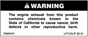
EBU17091
EBU17170
INTRODUCTION
EBU17270
Congratulations on your purchase of the Yamaha YFM66FGW. This ATV represents the result of many years of Yamaha experience in the production of fine sporting, touring, and pace-setting racing machines. With the purchase of this Yamaha, you can now appreciate the high degree of craftsmanship and reliability that have made Yamaha a leader in these fields.
This manual will provide you with a good basic understanding of the features and operation of this ATV.
This manual includes important safety information. It provides information about special techniques and skills necessary to ride the ATV. It also includes basic maintenance and inspection procedures. If you have any questions regarding the operation or maintenance of your ATV, please consult a Yamaha dealer.
AN IMPORTANT SAFETY MESSAGE:
●READ THIS MANUAL TOGETHER WITH TIPS FOR THE ATV RIDER CAREFULLY AND COMPLETELY BEFORE OPERATING YOUR ATV. MAKE SURE YOU UNDERSTAND ALL INSTRUCTIONS.
●PAY CLOSE ATTENTION TO THE WARNING AND CAUTION LABELS ON THE ATV.
●NEVER OPERATE AN ATV WITHOUT PROPER TRAINING OR INSTRUCTION. FREE TRAINING IS AVAILABLE TO ANYONE WHO BUYS A NEW ATV. CALL 1-800-887-2887 FOR MORE INFORMATION.
●THIS ATV, AND ANY OTHER ATV OVER 90 cc, SHOULD NOT BE RIDDEN BY ANYONE UNDER 16 YEARS OF AGE.

EBU17330
IMPORTANT MANUAL INFORMATION
EBU17341
FAILURE TO FOLLOW THE WARNINGS CONTAINED IN THIS MANUAL CAN RESULT IN SERIOUS INJURY OR DEATH.
Particularly important information is distinguished in this manual by the following notations:
The Safety Alert Symbol means ATTENTION! BECOME ALERT!
YOUR SAFETY IS INVOLVED!
|
Failure to follow WARNING instructions could result in severe injury |
||||
|
WARNING |
or death to the ATV operator, a bystander, or a person inspecting or |
|||
|
repairing the ATV. |
||||
|
A CAUTION indicates special precautions that must be taken to avoid |
||||
|
CAUTION: |
||||
|
damage to the ATV. |
||||
|
NOTE: |
A NOTE provides key information to make procedures easier or clearer. |
|||
* Product and specifications are subject to change without notice.
EBU17350
IMPORTANT NOTICE
EBU17360
Welcome to the Yamaha world of motor sports!
This ATV is designed and manufactured for OFF-ROAD use only. It is illegal and unsafe to operate this ATV on any public street, road or highway.
This ATV complies with all applicable OFF-ROAD noise level and spark arrester laws and regulations in effect at the time of manufacture.
Please check your local riding laws and regulations before operating this ATV.
EBU17381
|
YFM66FGW |
||
|
OWNER’S MANUAL |
||
|
©2006 by Yamaha Motor Corporation, U.S.A. |
||
|
1st edition, February 2006 |
||
|
AFFIX DEALER |
All rights reserved. |
|
|
Any reprinting or unauthorized use |
||
|
LABEL HERE |
without the written permission of |
|
|
Yamaha Motor Corporation, U.S.A. |
||
|
is expressly prohibited. |
||
|
Printed in Japan. |
||
|
P/N LIT-11626-20-05 |

EWB00010
 WARNING
Indicates a potential hazard that could result in serious injury or death.
EBU17420
TABLE OF CONTENTS
|
SAFETY INFORMATION ………………………… |
1-1 |
|
LOCATION OF THE WARNING AND |
|
|
SPECIFICATION LABELS ………………………. |
2-1 |
|
DESCRIPTION ………………………………………. |
3-1 |
|
Left view ……………………………………………… |
3-1 |
|
Right view……………………………………………. |
3-1 |
|
Controls and instruments ………………………. |
3-2 |
|
INSTRUMENT AND CONTROL |
|
|
FUNCTIONS ………………………………………….. |
4-1 |
|
Main switch ………………………………………… |
4-1 |
|
Indicator lights and warning light ……………. |
4-2 |
|
Multifunction display …………………………….. |
4-4 |
|
Handlebar switches ……………………………… |
4-6 |
|
Throttle lever …………………………………….. |
4-12 |
|
Speed limiter ……………………………………… |
4-13 |
|
Front brake lever ………………………………… |
4-14 |
|
Brake pedal and rear brake lever …………. |
4-14 |
|
Drive select lever ……………………………….. |
4-15 |
|
Recoil starter ……………………………………… |
4-15 |
|
Fuel tank cap …………………………………….. |
4-16 |
|
Fuel ………………………………………………….. |
4-16 |
|
Fuel cock ………………………………………….. |
4-18 |
|
Starter (choke) …………………………………… |
4-19 |
|
Seat …………………………………………………. |
4-20 |
|
Storage compartment …………………………. |
4-21 |
|
Front carrier ………………………………………. |
4-22 |
|
Rear carrier ……………………………………….. |
4-22 |
|
Adjusting the front and rear shock |
|
|
absorber assemblies …………………………. |
4-22 |
|
Auxiliary DC jack ………………………………… |
4-23 |
|
PRE-OPERATION CHECKS …………………….. |
5-1 |
|
Pre-operation check list ………………………… |
5-1 |
|
Fuel ……………………………………………………. |
5-4 |
|
Engine oil ……………………………………………. |
5-4 |
|
Final gear oil ……………………………………….. |
5-4 |
|
Differential gear oil ……………………………….. |
5-4 |
|
Coolant ………………………………………………. |
5-4 |
|
Front and rear brakes …………………………… |
5-5 |
|
Throttle lever ……………………………………….. |
5-6 |
|
Tires …………………………………………………… |
5-7 |
|
Measuring the tire pressure ………………….. |
5-8 |
|
Tire wear limit ……………………………………… |
5-9 |
|
Chassis fasteners ………………………………… |
5-9 |
|
Instruments, lights and switches ……………. |
5-9 |
|
OPERATION ………………………………………….. |
6-1 |
|
Starting a cold engine ………………………….. |
6-1 |
|
Starting a warm engine ………………………… |
6-3 |
|
Operating the drive select lever |
|
|
and driving in reverse …………………………. |
6-3 |
|
Engine break-in …………………………………… |
6-5 |
|
Parking ………………………………………………. |
6-6 |
|
Parking on a slope ………………………………. |
6-6 |
|
Accessories and loading ………………………. |
6-6 |
|
RIDING YOUR ATV ……………………………….. |
7-1 |
|
GETTING TO KNOW YOUR ATV…………… |
7-2 |
|
RIDE WITH CARE AND GOOD |
|
|
JUDGEMENT…………………………………….. |
7-2 |
|
BE CAREFUL WHERE YOU RIDE……….. |
7-12 |
|
TURNING YOUR ATV ………………………… |
7-18 |
|
CLIMBING UPHILL …………………………….. |
7-20 |
|
RIDING DOWNHILL……………………………. |
7-24 |
|
CROSSING A SLOPE…………………………. |
7-26 |
|
CROSSING THROUGH SHALLOW |
|
|
WATER …………………………………………… |
7-28 |
|
RIDING OVER ROUGH TERRAIN ……….. |
7-30 |
|
SLIDING AND SKIDDING ……………………. |
7-31 |
|
WHAT TO DO IF…………………………………. |
7-32 |
|
WHAT TO DO…………………………………….. |
7-32 |
|
PERIODIC MAINTENANCE AND MINOR |
|
|
REPAIR …………………………………………………. |
8-1 |
|
Owner’s manual and tool kit ………………….. |
8-1 |
|
Periodic maintenance chart for the |
|
|
emission control system ……………………… |
8-3 |
|
General maintenance and |
|
|
lubrication chart …………………………………. |
8-5 |
|
Removing and installing panels ……………… |
8-9 |
|
Checking the spark plug ……………………… |
8-16 |
|
Engine oil and oil filter cartridge ……………. |
8-18 |
|
Changing the final gear oil …………………… |
8-22 |
|
Differential gear oil ……………………………… |
8-23 |
|
Coolant …………………………………………….. |
8-25 |
|
Cleaning the air filter element ………………. |
8-29 |
|
Cleaning the spark arrester …………………. |
8-33 |
|
V-belt cooling duct check hose …………….. |
8-34 |
|
V-belt case drain plug …………………………. |
8-35 |
|
Adjusting the carburetor ………………………. |
8-35 |
|
Adjusting the engine idling speed …………. |
8-36 |
|
Adjusting the throttle cable free play ……… |
8-37 |
|
Valve clearance …………………………………. |
8-37 |
|
Adjusting the drive select lever safety |
|
|
system cable ……………………………………. |
8-38 |
|
Checking the front and rear brake pads … |
8-38 |
|
Checking the brake fluid level ……………… |
8-39 |
|
Changing the brake fluid …………………….. |
8-40 |
|
Checking the front brake lever |
|
|
free play …………………………………………. |
8-40 |
|
Adjusting the rear brake lever free play |
|
|
and checking the brake pedal position … |
8-41 |
|
Axle boots ………………………………………… |
8-43 |
|
Brake light switches …………………………… |
8-44 |
|
Checking and lubricating the cables …….. |
8-45 |
|
Checking and lubricating the front and |
|
|
rear brake levers ……………………………… |
8-45 |
|
Checking and lubricating the |
|
|
brake pedal …………………………………….. |
8-46 |
|
Checking the wheel bearings ………………. |
8-47 |
|
Lubricating the drive shaft |
|
|
universal joint ………………………………….. |
8-47 |
|
Checking the stabilizer bushes ……………. |
8-47 |
|
Lubricating the upper and lower |
|
|
arm pivots ……………………………………….. |
8-47 |
|
Lubricating the knuckle pivots ……………… |
8-47 |
|
Battery ……………………………………………… |
8-48 |
|
Replacing a fuse ……………………………….. |
8-50 |
|
Replacing a headlight bulb ………………….. |
8-51 |
|
Adjusting a headlight beam …………………. |
8-53 |
|
Replacing the tail/brake light bulb ………… |
8-53 |
|
Removing a wheel ……………………………… |
8-54 |
|
Installing a wheel ……………………………….. |
8-54 |
|
Troubleshooting …………………………………. |
8-56 |
|
Troubleshooting charts ……………………….. |
8-57 |
|
CLEANING AND STORAGE …………………….. |
9-1 |
|
Cleaning ……………………………………………… |
9-1 |
|
Storage ………………………………………………. |
9-2 |
|
SPECIFICATIONS ………………………………… |
10-1 |
|
CONSUMER INFORMATION………………….. |
11-1 |
|
Identification numbers …………………………. |
11-1 |
|
Noise regulation …………………………………. |
11-3 |
|
Maintenance record ……………………………. |
11-4 |
|
YAMAHA MOTOR CORPORATION, |
|
|
U.S.A. ATV LIMITED WARRANTY ……… |
11-5 |
|
YAMAHA EXTENDED SERVICE |
|
|
(Y.E.S.) …………………………………………… |
11-7 |

EBU17481
AN ATV IS NOT A TOY AND CAN BE HAZARDOUS TO OPERATE. An ATV handles differently from other vehicles, including motorcycles and cars. A collision or rollover can occur quickly, even during routine maneuvers such as turning and riding on hills or over obstacles, if you fail to take proper precautions.
SEVERE INJURY OR DEATH can result if you do not follow these instructions:
●Read this manual and all labels carefully and follow the operating procedures described.
●Never operate an ATV without proper training or instruction. Take a Training Course. Beginners should receive training from a certified instructor. Contact an authorized ATV dealer or call 1- 800-887-2887 to find out about the training courses nearest you.
●Always follow the age recommendation:
– A child under 16 years old should never operate an ATV with engine size greater than 90 cc.
●Never allow a child under age 16 to operate an ATV without adult supervision, and never allow continued use of an ATV by a child if he or she does not have the abilities to operate it safely.
●Never carry a passenger on an ATV.
●Always avoid operating an ATV on any paved surfaces, including sidewalks, driveways, parking lots and streets.
●Never operate an ATV on any public street, road or highway, even a dirt or gravel one.
●Never operate an ATV without wearing an approved motorcycle helmet that fits properly. You should also wear eye protection (goggles or face shield), gloves, boots, a long-sleeved shirt or a jacket, and long pants.
●Never consume alcohol or drugs before or while operating this ATV.
●Never operate at speeds too fast for your skills or the riding conditions. Always go at a speed that is proper for the terrain, visibility, operating conditions, and your experience.
●Never attempt wheelies, jumps, or other stunts.
1-1

●Always inspect your ATV each time you use it to make sure it is in safe operating condition. Al-
1ways follow the inspection and maintenance procedures and schedules described in this manual.
●Always keep both hands on the handlebars and both feet on the footboards of the ATV during operation.
●Always go slowly and be extra careful when operating on unfamiliar terrain. Always be alert to changing terrain conditions when operating the ATV.
●Never operate on excessively rough, slippery or loose terrain until you have learned and practiced the skills necessary to control the ATV on such terrain. Always be especially cautious on these kinds of terrain.
●Always follow proper procedures for turning as described in this manual. Practice turning at low speeds before attempting to turn at faster speeds and never turn at excessive speeds.
●Never operate the ATV on hills too steep for the ATV or for your abilities. Practice on smaller hills before attempting larger hills.
●Always follow proper procedures for climbing hills as described in this manual. Check the terrain carefully before you start up any hill. Never climb hills with excessively slippery or loose surfaces. Shift your weight forward. Never open the throttle suddenly. Never go over the top of a hill at high speed.
●Always follow proper procedures for going down hills and for braking on hills as described in this manual. Check the terrain carefully before you start down any hill. Shift your weight backward. Never go down a hill at high speed. Avoid going down a hill at an angle that would cause the vehicle to lean sharply to one side. Go straight down the hill where possible.
●Always follow proper procedures for crossing the side of a hill as described in this manual. Avoid hills with excessively slippery or loose surfaces. Shift your weight to the uphill side of the ATV. Never attempt to turn the ATV around on any hill until you have mastered the turning technique described in this manual on level ground. Avoid crossing the side of a steep hill if possible.
●Always use proper procedures if you stall or roll backwards when climbing a hill. To avoid stalling, use the proper gear range and maintain a
1-2
![]()
steady speed when climbing a hill. If you stall or roll backwards, follow the special procedure for braking described in this manual. Dismount on the uphill side or to a side if pointed straight uphill. Turn the ATV around and remount, following the procedure described in this manual.
●Always check for obstacles before operating in a new area.
●Never attempt to operate over large obstacles, such as large rocks or fallen trees. Always follow proper procedures when operating over obstacles as described in this manual.
●Always be careful when skidding or sliding. Learn to safely control skidding or sliding by practicing at low speeds and on level, smooth terrain. On extremely slippery surfaces, such as ice, go slowly and be very cautious in order to reduce the chance of skidding or sliding out of control.
●Never operate an ATV in fast flowing water or in water deeper than that recommended in this manual. Remember that wet brakes may have reduced stopping ability. Test your brakes after leaving water. If necessary, apply them several times to let friction dry out the linings.
|
● Always be sure there are no obstacles or people |
|
|
behind you when you operate in reverse. When |
1 |
|
it is safe to proceed in reverse, go slowly. |
●Always use the size and type of tires specified in this manual.
●Always maintain proper tire pressure as described in this manual.
●Never modify an ATV through improper installation or use of accessories.
●Never exceed the stated load capacity for an ATV. Cargo should be properly distributed and securely attached. Reduce speed and follow instructions in this manual for carrying cargo or
pulling a trailer. Allow greater distance for braking.
FOR MORE INFORMATION ABOUT ATV SAFETY, call the Consumer Products Safety Commission at 1-800-638-2772, or the ATV Distributor’s Safety Hotline at 1-800-852-5344.
1-3

EWB00021
 WARNING
1POTENTIAL HAZARD Improper handling of gasoline. WHAT CAN HAPPEN
Gasoline can catch fire and you could be burned.
HOW TO AVOID THE HAZARD
Always turn off the engine when refueling. Do not refuel right after the engine has been running and is still very hot.
Do not spill gasoline on the engine or exhaust pipe/muffler when refueling.
Never refuel while smoking, or in the vicinity of sparks, open flames, or other sources of ignition such as the pilot lights of water heaters and clothes dryers.
When transporting the ATV in another vehicle, be sure it is kept upright and that the fuel cock is in the “OFF” position. Otherwise, fuel may leak out of the carburetor or fuel tank.
WHAT CAN HAPPEN
Gasoline is poisonous and can cause injuries.
HOW TO AVOID THE HAZARD
If you should swallow some gasoline or inhale a lot of gasoline vapor, or get some gasoline in your eyes, seek medical help immediately. If gasoline spills on your skin, wash with soap and water. If gasoline spills on your clothing, change your clothes.
EWB00030
 WARNING
POTENTIAL HAZARD
Starting or running the engine in a closed area.
1-4
|
WHAT CAN HAPPEN |
||||
|
Exhaust fumes are poisonous and may |
||||
|
cause loss of consciousness and death |
1 |
|||
|
within a short time. |
||||
|
HOW TO AVOID THE HAZARD |
||||
|
Always operate your ATV in an area with ad- |
||||
|
equate ventilation. |
||||
1-5
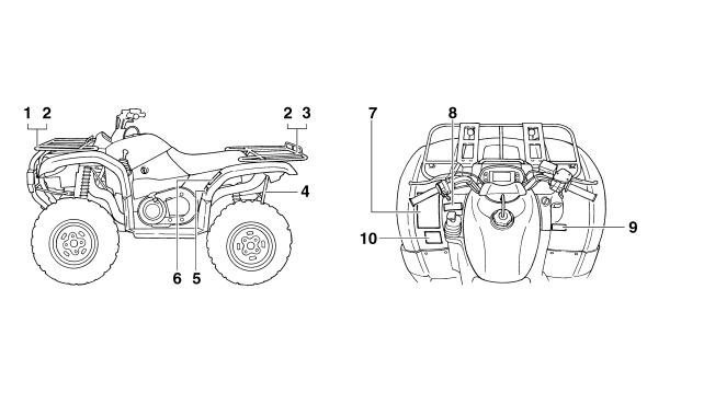
EBU17660
LOCATION OF THE WARNING AND SPECIFICATION LABELS
2
2-1
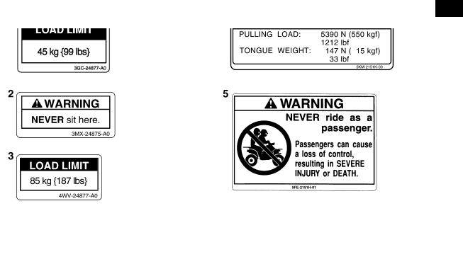
EBU17670
Read and understand all of the labels on your ATV. These labels contain important information for safe and proper operation.
Never remove any labels from your ATV. If a label becomes difficult to read or comes off, request a replace- 2 ment label from your Yamaha dealer.
2-2

2
2-3

2
2-4

EBU17680
EBU17690
Left view
3
1.Radiator cap
2.Fuel tank cap
3.Fuel cock
4.Oil filter cartridge
5.Throttle stop screw
6.Fuses
7.Engine oil dipstick
8.Recoil starter
9.Coolant reservoir
10.Drive select lever box check hose 11.V-belt cooling duct check hose
DESCRIPTION
EBU17700
Right view
1.Rear shock absorber assembly spring preload adjusting ring
2.Spark arrester
3.Storage compartment and tool kit
4.Battery
5.Air filter case
6.Spark plug
7.Front brake fluid reservoir
8.Front shock absorber assembly spring preload adjusting ring
9.Rear brake fluid reservoir
10.Brake pedal 11.V-belt case drain plug
3-1
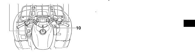
|
EBU17712 |
|||
Controls and instruments |
NOTE: |
||
|
The ATV you have purchased may differ slightly |
|||
|
from the figures shown in this manual. |
|||
3
1.Drive select lever
2.Rear brake lever
3.Handlebar switches
4.Starter (choke)
5.Multifunction meter unit
6.Main switch
7.On-Command four-wheel-drive/differential gear lock switch
8.Throttle lever
9.Front brake lever
10.Auxiliary DC jack
3-2

EBU17720
INSTRUMENT AND CONTROL FUNCTIONS
EWB00010
 WARNING
Indicates a potential hazard that could result in serious injury or death.
4 EBU17760
Main switch
The positions of the main switch are as follows:
ON
All electrical systems are supplied with power. The headlights and taillight come on when the light switch is on, and the engine can be started. The key cannot be removed.
OFF
All electrical systems are off. The key can be removed.
1. Main switch
4-1
![]()
EBU17811
Indicator lights and warning light
1.On-Command differential gear lock indicator light “DIFF. LOCK”
2.Low-range indicator light “L”
3.High-range indicator light “H”
4.Neutral indicator light “N”
5.Reverse indicator light “R”
6.Park indicator light “P”
7.On-Command four-wheel-drive/differential gear lock
indicator “  ”/“ DIFF. ”
LOCK
8. Coolant temperature warning light “  ”
”
EBU17840
Reverse indicator light “ ”
”
This indicator light comes on when the transmission is in the reverse position.
NOTE:
If the indicator light flashes or the speedometer does not show the speed while riding, have a Yamaha dealer check the speed sensor circuit.
EBU17860
Neutral indicator light “ ”
”
This indicator light comes on when the transmis- 4 sion is in the neutral position.
EBU17920
Coolant temperature warning light “  ”
”
This warning light comes on when the engine overheats. When this occurs during operation, stop the engine as soon as it is safe to do so and allow it to cool down for about 10 minutes.
ECB00010
CAUTION:
●The engine may overheat if the ATV is overloaded. In this case, reduce the load to specification.
●Start the engine after making sure that the warning light is out. Continuous use while the warning light is on may cause damage to the engine.
4-2

EBU17961
On-Command four-wheel-drive/differential
gear lock indicator “ ”/“ DIFF. ”
LOCK
The On-Command four-wheel-drive indicator “  ” comes on when the On-Command four-wheel- drive switch is set to the “4WD” position.
The On-Command differential gear lock indicator
“DIFF. ” in the On-Command four-wheel-drive indica-
LOCK
4 tor also comes on when the On-Command differential gear lock switch is set to the “LOCK” position.
NOTE:
● Due to the synchronizing mechanism in the differential gear case, the four-wheel-drive indicator may not come on until the ATV starts moving.
● When the On-Command differential gear lock
switch is set to “LOCK”, the indicator “ DIFF. ” will
LOCK
flash until the differential gear is locked.
EBU17970
Park indicator light “  ”
”
This indicator light comes on when the transmission is in the park position.
EBU17980
High-range indicator light “  ”
”
This indicator light comes on when the transmission is in the high-range position.
EBU17990
Low-range indicator light “  ”
”
This indicator light comes on when the transmission is in the low-range position.
EBU18001
On-Command differential gear lock indicator light “DIFF. LOCK”
This indicator light and the On-Command differential gear lock indicator in the display come on when the On-Command differential gear lock switch is set to the “LOCK” position.
NOTE:
When the switch is set to “LOCK”, the On-Com- mand differential gear lock indicator light will flash until the differential gear is locked.
4-3
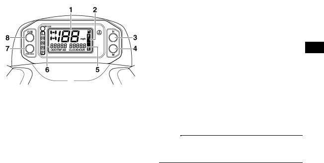
EBU18040
Multifunction display
1.Speedometer
2.Fuel meter
3.“H” button
4.“M” button
5.Clock/Hour meter
6.Odometer/Tripmeter A/Tripmeter B
7.TRIP/ODO button
8.Clock/Hour “  ”/“
”/“  ” button
The multifunction display is equipped with the following:
●a speedometer (which shows the riding speed)
●an odometer (which shows the total distance traveled)
●two tripmeters (which show the distance traveled since they were last set to zero)
●a clock
●an hour meter (which shows the total time the key has been turned to “ON”)
●a fuel meter
Odometer and tripmeter modes
Pushing the “TRIP/ODO” button switches the dis- 4 play between the odometer mode “ODO” and the tripmeter modes “A” and “B” in the following order: ODO → TRIP A → TRIP B → ODO
To reset a tripmeter, select it by pushing the “TRIP/ODO” button, and then push the “TRIP/ODO” button for at least three seconds. The tripmeters can be used to estimate the distance that can be traveled with a full tank of fuel. This information will enable you to plan future fuel stops.
NOTE:
Holding in the “TRIP/ODO” button and then turning the key to “ON” switches the display between “mph” and “km/h”.
4-4

Clock mode
Pushing the “  ”/“
”/“  ” button switches the display between the clock mode “CLOCK” and the hour meter mode “HOUR” in the following order:
CLOCK → HOUR → CLOCK
To set the clock
1. Set the display to the clock mode.
42. Push the “  ”/“
”/“  ” button until the clock starts flashing.
3.Set the hours by pushing the “H” button.
4.Set the minutes by pushing the “M” button.
5.Push the “  ”/“
”/“  ” button, and then release it to start the clock.
Fuel meter
The fuel meter indicates the amount of fuel in the fuel tank. The display segments of the fuel meter disappear from “F” (full) towards “E” (empty) as the fuel level decreases. When the “E” segment disappears and the fuel level warning indicator flashes, set the fuel cock to reserve and refuel as soon as possible.
1.Fuel level warning indicator
2.Fuel meter
3.“E” segment
4-5

EBU18060
Handlebar switches
1.Light switch “  /
/  /OFF”
/OFF”
2.Start switch “  ”
”
|
3. |
Engine stop switch “ / |
” |
|
4. |
Override switch “OVERRIDE” |
|
|
EBU18080 |
||
|
Engine stop switch “ |
/ ” |
Set this switch to “  ” before starting the engine. The engine stop switch controls the ignition and stops the engine when it is running. Use this switch to stop the engine in an emergency situation. The engine will not start or run when this switch is set to “
 ”.
”.
EBU18100
Start switch “ ”
”
Push this switch to crank the engine with the starter.
ECB00050
CAUTION:
See the starting instructions on page 6-1 prior to starting the engine.
4
|
EBU18151 |
|
|
Light switch “ / |
/OFF” |
|
Set this switch to “ |
” to turn on the low beams |
and the taillight. Set the switch to “  ” to turn on the high beams and the taillight. Set the switch to “OFF” to turn off all the lights.
ECB00040
CAUTION:
Do not use the headlights with the engine turned off for an extended period of time, otherwise the battery may discharge to the point that the starter motor will not operate properly. If this should happen, remove the battery and recharge it.
4-6
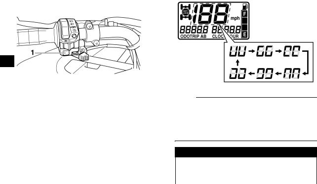
EBU18180
Override switch “OVERRIDE”
4
1. Override switch “OVERRIDE”
Top speed is normally limited when operating in differential gear lock. If conditions require more engine power when riding forward, push and hold this switch to override the differential gear lock speed limiting function. (See page 4-9.) Releasing the switch restores the speed limiting function.
While the override switch is pushed, the segments of the speedometer digits will appear as shown in the figure.
NOTE:
If the digits of the speedometer appear as shown when the switch is NOT being pushed, this could indicate a malfunction in the electrical system. In this case, take the ATV to a Yamaha dealer at the first opportunity.
EWB00110
 WARNING
POTENTIAL HAZARD
Riding too fast while the ATV is in four- wheel-drive differential gear lock.
4-7

WHAT CAN HAPPEN
All wheels turn at the same speed when the differential is locked, so it takes more effort to turn the ATV. The effort needed to turn increases with the riding speed. You may lose control and have an accident if you cannot make a sharp enough turn for the speed you are traveling.
HOW TO AVOID THE HAZARD
Always ride at a slow speed when the ATV is in four-wheel-drive differential gear lock, and allow extra time and distance for maneuvers.
EBU26632
On-Command four-wheel-drive switch “2WD”/“4WD”
This ATV is equipped with a switch to change from two-wheel drive to four-wheel drive and vice-versa. Select the appropriate drive according to the terrain and the conditions.
●“2WD” (two-wheel drive): Power is supplied to the rear wheels.
●“4WD” (four-wheel drive): Power is supplied to the rear and front wheels.
To change from two-wheel drive to four-wheel drive, stop the ATV and push the switch in to the “4WD” position. Then, the four-wheel-drive indicator “  ” comes on in the multifunction meter unit display.
To change from four-wheel drive to two-wheel drive, stop the ATV and push the switch in to the
“2WD” position.
4
1. On-Command four-wheel-drive switch “2WD”/“4WD”
4-8

EWB00120
 WARNING
POTENTIAL HAZARD
Changing from two-wheel drive to fourwheel drive or from four-wheel drive to twowheel drive while the ATV is moving.
WHAT CAN HAPPEN
4
The ATV handles differently in two-wheel drive than in four-wheel drive in some circumstances. Changing from two-wheel drive to four-wheel drive or from four-wheel drive to two-wheel drive while moving may cause the ATV to unexpectedly handle differently. This could distract the operator and increase the risk of losing control and of causing an accident.
HOW TO AVOID THE HAZARD
Always stop the ATV before changing from two-wheel drive to four-wheel drive or viceversa.
EBU18242
On-Command differential gear lock switch “4WD”/“LOCK”
This ATV is equipped with a switch allowing you to lock the differential gear when in four-wheel drive. Select the appropriate switch position according to the terrain and the conditions.
●“4WD” (four-wheel drive): Power is supplied to the rear and front wheels.
●“LOCK” (four-wheel drive with the differential gear locked): Power is supplied to the rear and front wheels and the differential gear is locked. Unlike in four-wheel drive, all wheels turn at the same speed.
1.On-Command four-wheel-drive switch “2WD”/“4WD”
2.On-Command differential gear lock switch “4WD”/“LOCK”
4-9
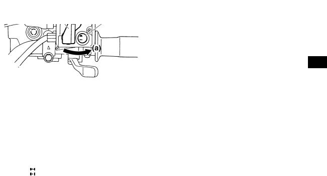
DIFF.
LOCK
To lock the differential gear in four-wheel drive, make sure the On-Command four-wheel-drive switch is pushed in to the “4WD” position.
4
1. On-Command differential gear lock switch “4WD”/“LOCK”
To release the differential gear lock, stop the ATV and push the switch to the “4WD” position.
1.Differential gear lock lever
2.On-Command four-wheel-drive switch “2WD”/“4WD”
Stop the ATV, move the differential gear lock lever to position (a), and then push the differential gear lock switch in to the “LOCK” position. When the differential gear is locked, the differential gear lock indicator “DIFF. LOCK” will come on along with the indicator “  ” in the multifunction meter display.
4-10

EWB00091
 WARNING
POTENTIAL HAZARD
Changing from four-wheel drive to four- wheel-drive differential gear lock or vice-ver- sa while the ATV is moving.
WHAT CAN HAPPEN
4
The ATV handles differently in four-wheel drive than in differential gear lock in some circumstances. Changing from four-wheel drive to differential gear lock or vice-versa while moving may cause the ATV to handle differently unexpectedly. This could distract the operator and increase the risk of losing control and causing an accident.
HOW TO AVOID THE HAZARD
Always stop the ATV before changing from four-wheel drive to four-wheel-drive differential gear lock or vice-versa.
EWB00101
 WARNING
POTENTIAL HAZARD
Riding too fast while the ATV is in four- wheel-drive differential gear lock.
WHAT CAN HAPPEN
All wheels turn at the same speed when the differential gear is locked, so it takes more effort to turn the ATV. The effort needed to turn increases with the riding speed. You may lose control and have an accident if you cannot make a sharp enough turn for the speed you are traveling.
HOW TO AVOID THE HAZARD
Always ride at a slow speed when the ATV is in differential gear lock, and allow extra time and distance for maneuvers.
NOTE:
●When the switch is set to “LOCK”, the differential gear lock indicator and indicator light will flash until the differential gear is locked.
●When the indicator and indicator light are flashing, turning the handlebar back and forth will help the differential gear lock to engage.
●Riding before the differential gear lock is properly engaged (e.g., when the indicator and indicator light are flashing) will cause the engine speed to be limited until engagement is complete.
4-11
![]()
●When the ATV is in four-wheel-drive differential gear lock, the maximum traveling speed is limited to 35 km/h (22 mi/h). However, if conditions require full engine power to be available, push and hold the override switch to disable the differential gear lock speed limiter. (See page 4-7 for a detailed explanation of this switch.)
EBU18270
Throttle lever
Once the engine is running, movement of the throttle lever will increase the engine speed.
Regulate the speed of the ATV by varying the throttle position. Because the throttle is springloaded, the ATV will decelerate, and the engine will return to an idle any time the hand is removed from the throttle lever.
4
1. Throttle lever
Before starting the engine, check the throttle to be sure it is operating smoothly. Make sure it returns to the idle position as soon as the lever is released.
4-12

EWB00200
 WARNING
POTENTIAL HAZARD Malfunction of throttle. WHAT CAN HAPPEN
The throttle could be hard to operate, making it difficult to speed up or slow down
4
when you need to. This could cause an accident.
HOW TO AVOID THE HAZARD
Check the operation of the throttle lever before you start the engine. If it does not work smoothly, check for the cause. Correct the problem before riding the ATV. Consult a Yamaha dealer if you can’t find or solve the problem yourself.
EBU18311
Speed limiter
Your ATV was delivered with an adjustable speed limiter. The speed limiter keeps the throttle from fully opening, even when the throttle lever is pushed to the maximum.
1.Loosen the locknut.
2.To increase the maximum engine power available and the maximum speed of the ATV, turn the adjusting screw in direction (a). To de-
crease the maximum engine power available and the maximum speed of the ATV, turn the adjusting screw in direction (b).
1.Locknut
2.Adjusting screw
3.No more than 12 mm (0.47 in)
3.Tighten the locknut.
EWB00190
 WARNING
POTENTIAL HAZARD
Improper adjustment of the speed limiter and throttle.
4-13

WHAT CAN HAPPEN
The throttle cable could be damaged. Improper throttle operation could result. You could lose control, have an accident or be injured.
HOW TO AVOID THE HAZARD
Do not turn the adjusting screw out more than 12 mm (0.47 in). Always make sure the throttle lever free play is adjusted to 3.0–5.0 mm (0.12–0.20 in). (See page 8-37.)
EBU18391
Front brake lever
The front brake lever is located on the right handlebar. To apply the front brake, pull the brake lever toward the handlebar grip.
4
1. Front brake lever
EBU18442
Brake pedal and rear brake lever
The brake pedal is located on the right side of the ATV and the rear brake lever is located on the left handlebar. To apply the rear brake, push down on the brake pedal or pull the brake lever toward the handlebar grip.
4-14

4
1. Brake pedal
1. Rear brake lever
EBU18611
Drive select lever
The drive select lever is used to shift your ATV into the low-range, high-range, neutral, reverse and park positions. See the “Operating the drive select lever and driving in reverse” section on page 6-3 for the drive select lever operation.
1. Drive select lever
EBU18680
Recoil starter
Firmly grasp the handle and pull slightly until engagement can be felt. Then pull forcefully, being careful not to pull the rope all the way out.
4-15

1. Recoil starter
EWB00290
 WARNING
POTENTIAL HAZARD
Starting the engine without setting the drive select lever to the park position.
WHAT CAN HAPPEN
The ATV could start to move unexpectedly, which could cause an accident.
HOW TO AVOID THE HAZARD
Set the drive select lever to the park position before starting the engine.
EBU18720
Fuel tank cap
Remove the fuel tank cap by turning it counterclockwise.
4
1. Fuel tank cap
EBU18730
Fuel
Make sure that there is sufficient fuel in the tank. Fill the fuel tank to the bottom of the filler tube as shown.
4-16

4
1.Fuel level
2.Fuel tank filler tube
Recommended fuel: UNLEADED GASOLINE ONLY
Fuel tank capacity:
20.0 L (5.28 US gal) (4.40 Imp.gal) Fuel reserve amount:
3.5 L (0.92 US gal) (0.77 Imp.gal)
ECB00070
CAUTION:
Use only unleaded gasoline. The use of leaded gasoline will cause severe damage to internal engine parts, such as the valves and piston rings, as well as to the exhaust system.
Your Yamaha engine has been designed to use regular unleaded gasoline with a pump octane number [(R+M)/2] of 86 or higher, or a research octane number of 91 or higher. If knocking or pinging occurs, use a different brand of gasoline or premium unleaded fuel. Unleaded fuel will give you longer spark plug life and reduced maintenance cost.
Gasohol
There are two types of gasohol: gasohol containing ethanol and that containing methanol. Gasohol containing ethanol can be used if the ethanol content does not exceed 10%. Gasohol containing methanol is not recommended by Yamaha because it can cause damage to the fuel system or ATV performance problems.
EWB00270
 WARNING
POTENTIAL HAZARD
Improper care when refueling.
4-17

WHAT CAN HAPPEN
Fuel can spill, which can cause a fire and severe injury.
Fuel expands when it heats up. If the fuel tank is overfilled, fuel could spill out due to heat from the engine or the sun.
HOW TO AVOID THE HAZARD
Do not overfill the fuel tank. Be careful not to spill fuel, especially on the engine or exhaust pipe. Wipe up any spilled fuel immediately. Be sure the fuel tank cap is closed securely.
Do not refuel right after the engine has been running and is still very hot.
EBU18820
Fuel cock
The fuel cock supplies fuel from the tank to the carburetor while also filtering it.
The fuel cock lever positions are explained as follows and shown in the illustrations.
OFF
4
1. Arrow mark pointing to “OFF”
With the fuel cock lever in this position, fuel will not flow. Always turn the fuel cock lever to this position when the engine is not running.
4-18

1. Arrow mark pointing to “ON”
With the fuel cock lever in this position, fuel flows to the carburetor. Turn the fuel cock lever to this position when starting the engine and riding.
1. Arrow mark pointing to “RES”
This indicates reserve. With the fuel cock lever in this position, the fuel reserve is made available. Turn the fuel cock lever to this position if you run out of fuel while riding. When this occurs, refuel as soon as possible and be sure to turn the fuel cock lever back to “ON”!
EBU18850
Starter (choke) “ 

 ”
”
Starting a cold engine requires a richer air-fuel mixture, which is supplied by the starter (choke). Move the starter (choke) in direction (a) to turn on the starter (choke).
4-19

Move the starter (choke) in direction (b) to turn off the starter (choke).
See the “Starting a cold engine” section on page 6-1 for proper operation.
1. Starter (choke) “ 

 ”
”
EBU18880
Seat
To remove the seat
Pull the seat lock lever upward and pull up the seat at the rear.
4
1.Seat
2.Seat lock lever
To install the seat
Insert the projections on the front of the seat into the seat holders and push down on the seat at the rear.
NOTE:
Make sure that the seat is securely fitted.
4-20

4
1.Projection
2.Seat holder
EBU27090
Storage compartment
The storage compartment is located under the seat. (See page 4-20.)
When storing the owner’s manual or other documents in the storage compartment, be sure to wrap them in a plastic bag so that they will not get wet. When washing the ATV, be careful not to let any water enter the storage compartment.
ECB00130
CAUTION:
Do not store metal or sharply edged objects, like tools, in the storage compartment. If they must be stored, wrap them in appropriate cushion material to prevent damaging the storage compartment.
1. Storage compartment
●Do not exceed the load limit of 2.0 kg (4 lb) for the storage compartment.
●Do not exceed the maximum load of 220.0 kg (485 lb) for the ATV.
4-21
![]()
EBU18960
Front carrier
●Do not exceed the load limit of 45.0 kg (99 lb) for the front carrier.
●Do not exceed the maximum load of 220.0 kg (485 lb) for the ATV.
EBU18970
Rear carrier
●Do not exceed the load limit of 85.0 kg (187 lb) for the rear carrier.
●Do not exceed the maximum load of 220.0 kg (485 lb) for the ATV.
EBU19150
Adjusting the front and rear shock absorber assemblies
The spring preload can be adjusted to suit the rider’s weight and the riding conditions.
NOTE:
The rear wheels need to be removed to adjust the rear shock absorber assemblies. (See page 8-54.)
Adjust the spring preload as follows.
Turn the adjusting ring in direction (a) to increase the spring preload and thereby harden the suspension, and in direction (b) to decrease the spring preload and thereby soften the suspension.
4
1.Spring preload adjusting ring
2.Position indicator
NOTE:
A special wrench can be obtained at a Yamaha dealer to make this adjustment.
4-22

4
1. Special wrench
Spring preload setting: Minimum (soft):
1
Standard:
2
Maximum (hard): 5
EWB00350
 WARNING
POTENTIAL HAZARD
Improper shock absorber assembly adjustment.
WHAT CAN HAPPEN
Uneven adjustment can cause poor handling and loss of stability, which could lead to an accident.
HOW TO AVOID THE HAZARD
Always adjust the shock absorber assemblies on the left and right side to the same setting.
EBU19180
Auxiliary DC jack
The auxiliary DC jack is located at the front right side of the ATV. The auxiliary DC jack can be used for suitable work lights, radios, etc. The auxiliary DC jack should only be used when the engine is running.
1.Set the light switch to “OFF”.
2.Start the engine. (See page 6-1.)
3.Open the auxiliary DC jack cap, and then insert the accessory power plug into the jack.
4-23

1. Auxiliary DC jack cap
1. Auxiliary DC jack
Maximum rated capacity for the auxiliary DC jack:
DC 12 V, 120 W (10 A)
4. When the auxiliary DC jack is not being used, cover it with the cap.
ECB00120
CAUTION:
4
●Do not use accessories requiring more than the above maximum capacity. This may overload the circuit and cause the fuse to blow.
●If accessories are used without the engine running or with the headlights turned on, the battery will lose its charge and engine starting may become difficult.
●Do not use an automotive cigarette lighter or other accessories with a plug that gets hot because the jack can be damaged.
EWB00010
 WARNING
Indicates a potential hazard that could result in serious injury or death.
4-24

EBU19200
PRE-OPERATION CHECKS
EBU19210
Pre-operation check list
Before operating this ATV, be sure to check the items listed in the following table.
NOTE:
The maintenance of some items in the table has to be performed by a Yamaha dealer. Refer to the “Periodic maintenance and lubrication chart” on page 8-3 to determine which service should be performed by a
Yamaha dealer.
5
|
ITEM |
ROUTINE |
PAGE |
||
|
Fuel |
• Check fuel level in fuel tank, and add recommended fuel if neces- |
|||
|
sary. |
4-16, 5-4 |
|||
|
• Check fuel line for leakage. Correct if necessary. |
||||
|
Engine oil |
• Check oil level in engine, and add recommended oil to specified lev- |
|||
|
el if necessary. |
5-4, |
8-18 |
||
|
• Check ATV for oil leakage. Correct if necessary. |
||||
|
Final gear oil |
• Check ATV for oil leakage. Correct if necessary. |
5-4, |
8-22 |
|
|
Differential gear oil |
• Check ATV for oil leakage. Correct if necessary. |
5-4, |
8-23 |
|
|
Coolant |
• Check coolant level in reservoir, and add recommended coolant to |
|||
|
specified level if necessary. |
5-4, |
8-25 |
||
|
• Check cooling system for leakage. Correct if necessary. |
||||
|
• Check operation. If soft or spongy, have Yamaha dealer bleed hy- |
||||
|
draulic system. |
||||
|
Front brake |
• Check brake pads for wear, and replace if necessary. |
5-5, 8-38, |
8-39, 8-40 |
|
|
• Check brake fluid level in reservoir, and add recommended brake |
||||
|
fluid to specified level if necessary. |
||||
|
• Check hydraulic system for leakage. Correct if necessary. |
||||
5-1
|
ITEM |
ROUTINE |
PAGE |
||||
|
• Check operation. If soft or spongy, have Yamaha dealer bleed hy- |
||||||
|
draulic system. |
||||||
|
Rear brake |
• Check lever free play, and adjust if necessary. |
|||||
|
• Check brake pads for wear, and replace if necessary. |
5-5, 8-38, 8-39, 8-41 |
|||||
|
• Check brake fluid level in reservoir, and add recommended brake |
||||||
|
fluid to specified level if necessary. |
||||||
|
• Check hydraulic system for leakage. Correct if necessary. |
||||||
|
Throttle lever |
• Make sure that operation is smooth. Lubricate cable and lever hous- |
|||||
|
ing if necessary. |
5-6, 8-37 |
|||||
|
• Check cable free play, and adjust if necessary. |
||||||
|
Control cables |
• Make sure that operation is smooth. Lubricate if necessary. |
8-45 |
5 |
|||
|
Wheels and tires |
• Check wheel condition, and replace if damaged. |
|||||
|
• Check tire condition and tread depth. Replace if necessary. |
5-7, 5-8, 5-9 |
|||||
|
• Check air pressure. Correct if necessary. |
||||||
|
Brake pedal |
• Make sure that operation is smooth. Lubricate pedal pivoting point if |
8-46 |
||||
|
necessary. |
||||||
|
Brake levers |
• Make sure that operation is smooth. Lubricate lever pivoting points if |
8-45 |
||||
|
necessary. |
||||||
|
Axle boots |
• Check for cracks or damage, and replace if necessary. |
8-43 |
||||
|
Chassis fasteners |
• Make sure that all nuts, bolts and screws are properly tightened. |
5-9 |
||||
|
Instruments, lights and |
• Check operation, and correct if necessary. |
5-9 |
||||
|
switches |
||||||
5-2

EWB00470
 WARNING
POTENTIAL HAZARD
Failure to inspect the ATV before operating. Failure to properly maintain the ATV. WHAT CAN HAPPEN
Increases the possibility of an accident or equipment damage. HOW TO AVOID THE HAZARD
Always inspect your ATV each time you use it to make sure it is in safe operating condition.
5Always follow the inspection and maintenance procedures and schedules described in the Owner’s Manual.
5-3

EBU19530
Fuel
Make sure that there is sufficient fuel in the tank. (See page 4-16.)
EWB00500
 WARNING
POTENTIAL HAZARD Improper care when refueling. WHAT CAN HAPPEN
Fuel can spill, which can cause a fire and severe injury.
Fuel expands when it heats up. If the fuel tank is overfilled, fuel could spill out due to heat from the engine or the sun.
HOW TO AVOID THE HAZARD
Do not overfill the fuel tank. Be careful not to spill fuel, especially on the engine or exhaust pipe. Wipe up any spilled fuel immediately. Be sure the fuel tank cap is closed securely.
Do not refuel right after the engine has been running and is still very hot.
EBU19560
Engine oil
Make sure that the engine oil is at the specified level. Add oil as necessary. (See page 8-18.)
EBU19590
Final gear oil
Make sure that the final gear oil is at the specified level. Add oil as necessary. (See page 8-22.)
EBU19600
Differential gear oil
Make sure that the differential gear oil is at the specified level. Add oil as necessary. (See page 8-23.)
5
EBU19620
Coolant
Make sure that the coolant is at the specified level. Add coolant as necessary. (See page 8-25.)
NOTE:
The coolant level must be checked on a cold engine since the level varies with engine temperature.
5-4

EWB00490
 WARNING
POTENTIAL HAZARD
Removing the radiator cap when the engine and radiator are still hot.
WHAT CAN HAPPEN
You could be burned by hot fluid and steam blown out under pressure.
HOW TO AVOID THE HAZARD
5Wait for the engine to cool before removing the radiator cap. Always use a thick rag over the cap. Allow any remaining pressure to escape before completely removing the cap.
EBU19720
Front and rear brakes
Brake levers and brake pedal
●Check that there is no free play in the front brake lever. If there is free play, have a Yamaha dealer adjust it.
●Check for correct free play in the rear brake lever. If the free play is incorrect, adjust it. (See page 8-41.)
●Check for correct brake pedal height. If the pedal height is incorrect, have a Yamaha dealer adjust it.
●Check the operation of the brake levers and pedal. They should move smoothly and there should be a firm feeling when the brakes are applied. If not, have a Yamaha dealer check the brake system.
Brake fluid level
Check the brake fluid level. Add fluid if necessary. (See page 8-39.)
Recommended brake fluid:
DOT 4
Brake fluid leakage
Check to see if any brake fluid is leaking out of the pipe joints or brake fluid reservoirs. Apply the brakes firmly for one minute. If a lever moves slowly inward, there may be a leak in the brake system. If there is any leakage, the brake system should be checked by a Yamaha dealer.
Brake operation
Test the brakes at slow speed after starting out to make sure they are working properly. If the brakes do not provide proper braking performance, check the brake pads for wear. (See page 8-38.)
5-5

EWB00540
 WARNING
POTENTIAL HAZARD
Riding with improperly operating brakes. WHAT CAN HAPPEN
You could lose braking ability, which could lead to an accident.
HOW TO AVOID THE HAZARD
Always check the brakes at the start of every
ride. Do not ride the ATV if you find any prob- 5 lem with the brakes. If a problem cannot be
corrected by the adjustment procedures provided in this manual, have a Yamaha dealer check for the cause.
EBU19761
Throttle lever
Check the operation of the throttle lever. It must open smoothly and spring back to the idle position when released. Have a Yamaha dealer correct if necessary.
5-6

EBU19781
Tires
EWB00561
 WARNING
POTENTIAL HAZARD
Operating this ATV with improper tires, or with improper or uneven tire pressure. WHAT CAN HAPPEN
Use of improper tires on this ATV, or operation of this ATV with improper or uneven tire
5pressure, may cause loss of control, increasing your risk of accident.
HOW TO AVOID THE HAZARD
●The tires listed below have been approved by Yamaha Motor Co., Ltd. for this model. Other tire combinations are not recommended.
Front:
Manufacturer/model:
DUNLOP/KT131
Size:
AT25 x 8-12 Type:
Tubeless
Rear:
Manufacturer/model:
DUNLOP/KT135
Size:
AT25 x 10-12
Type:
Tubeless
●The tires should be set to the recommended pressure:
Recommended tire pressure: Front:
35 kPa (5.0 psi) (0.35 kgf/cm²) Rear:
30 kPa (4.3 psi) (0.30 kgf/cm²)
•Check and adjust tire pressures when the tires are cold.
•Tire pressures must be equal on both sides.
5-7
 Loading…