
- Manuals
- Brands
- Yamaha Manuals
- Motorcycle
- FJR1300A(D)
- Service manual
-
Contents
-
Table of Contents
-
Troubleshooting
-
Bookmarks
Related Manuals for Yamaha FJR1300A(D)
Summary of Contents for Yamaha FJR1300A(D)
-
Page 1
2013 SERVICE MANUAL FJR1300A(D) 1MC-28197-E0… -
Page 2
EAS20040 FJR1300A(D) 2013 SERVICE MANUAL ©2012 by Yamaha Motor Co., Ltd. First edition, August 2012 All rights reserved. Any reproduction or unauthorized use without the written permission of Yamaha Motor Co., Ltd. is expressly prohibited. -
Page 3
EAS20071 IMPORTANT This manual was produced by the Yamaha Motor Company, Ltd. primarily for use by Yamaha dealers and their qualified mechanics. It is not possible to include all the knowledge of a mechanic in one man- ual. Therefore, anyone who uses this book to perform maintenance and repairs on Yamaha vehicles should have a basic understanding of mechanics and the techniques to repair these types of vehicles. -
Page 4: How To Use This Manual
EAS20090 HOW TO USE THIS MANUAL This manual is intended as a handy, easy-to-read reference book for the mechanic. Comprehensive explanations of all installation, removal, disassembly, assembly, repair and check procedures are laid out with the individual steps in sequential order. •…
-
Page 5: Symbols
EAS20101 SYMBOLS The following symbols are used in this manual for easier understanding. The following symbols are not relevant to every vehicle. SYMBOL DEFINITION SYMBOL DEFINITION Serviceable with engine mounted Gear oil Filling fluid Molybdenum disulfide oil Lubricant Brake fluid Special tool Wheel bearing grease Tightening torque…
-
Page 7: Table Of Contents
EAS20110 TABLE OF CONTENTS GENERAL INFORMATION SPECIFICATIONS PERIODIC CHECKS AND ADJUSTMENTS CHASSIS ENGINE COOLING SYSTEM FUEL SYSTEM ELECTRICAL SYSTEM TROUBLESHOOTING…
-
Page 9: General Information
MODEL LABEL………………1-1 FEATURES…………………. 1-2 OUTLINE OF THE FI SYSTEM…………..1-2 FI SYSTEM………………..1-3 YCC-T (Yamaha Chip Controlled Throttle)……….1-4 OUTLINE OF THE CRUISE CONTROL SYSTEM……..1-6 OUTLINE OF THE UNIFIED BRAKE SYSTEM ……..1-13 OUTLINE OF THE ABS…………….1-15 ABS COMPONENT FUNCTIONS …………1-19 ABS OPERATION ……………….1-25…
-
Page 10: Identification
IDENTIFICATION EAS20130 IDENTIFICATION EAS20140 VEHICLE IDENTIFICATION NUMBER The vehicle identification number “1” is stamped into the right side of the steering head pipe. EAS20150 MODEL LABEL The model label “1” is affixed to the frame. This information will be needed to order spare parts.
-
Page 11: Features
FEATURES EAS20170 FEATURES ET2C01025 OUTLINE OF THE FI SYSTEM The main function of a fuel supply system is to provide fuel to the combustion chamber at the optimum air-fuel ratio in accordance with the engine operating conditions and the atmospheric temperature. In the conventional carburetor system, the air-fuel ratio of the mixture that is supplied to the combustion chamber is created by the volume of the intake air and the fuel that is metered by the jet used in the respective carburetor.
-
Page 12: Fi System
FEATURES ET3P61042 FI SYSTEM The fuel pump delivers fuel to the fuel injector via the fuel filter. The pressure regulator maintains the fuel pressure that is applied to the fuel injector at only 324 kPa (3.24 kg/cm², 47.0 psi). Accordingly, when the energizing signal from the ECU energizes the fuel injector, the fuel passage opens, causing the fuel to be injected into the intake manifold only during the time the passage remains open.
-
Page 13: Ycc-T (Yamaha Chip Controlled Throttle)
Yamaha developed the YCC-T system employing the most advanced electronic control technologies. Electronic control throttle systems have been used on automobiles, but Yamaha has developed a fast- er, more compact system specifically for the needs of a sports motorcycle. The Yamaha-developed system has a high-speed calculating capacity that produces computations of running conditions every 1/1000th of a second.
-
Page 14
FEATURES YCC-T system outline 1. Throttle position sensor 2. Throttle servo motor 3. Accelerator position sensor 4. ECU (engine control unit) 5. Sensor input 6. Gear position switch 7. Crankshaft position sensor 8. Rear wheel sensor 9. Coolant temperature sensor… -
Page 15: Outline Of The Cruise Control System
FEATURES EAS1MC1087 OUTLINE OF THE CRUISE CONTROL SYSTEM This model is equipped with a cruise control system designed to maintain a set cruising speed. Be- cause the vehicle is equipped with the YCC-T system, the cruise control system can be controlled elec- tronically.
-
Page 16
FEATURES EWA1MC1006 WARNING • Improper use of the cruise control system may result in loss of control, which could lead to an accident. Do not activate the cruise control system in heavy traffic, poor weather conditions, or among winding, slippery, hilly, rough or gravel roads. •… -
Page 17
FEATURES Deactivating the cruise control system Perform one of the following operations to cancel the set cruising speed. The cruise control setting in- dicator light “SET” will go off. • Turn the throttle grip past the closed position in the deceleration direction. •… -
Page 18
FEATURES Operation chart A. Operation a. Cruise control power switch “ ” “ON” B. Indication b. Manual acceleration C. Speed c. Push the “SET–” side of the cruise control setting switch D. 180 km/h (112 mph) d. Currently set cruising speed increases E. -
Page 19
Because the automatic deactivation of the cruise control system is stored in the memory of the ECU, the deactivation can be checked using the Yamaha diagnostic tool. In some cases, the cruise control system may not be able to maintain the set cruising speed when the vehicle is traveling uphill or downhill. -
Page 20
FEATURES Meter displays during cruise control system operation A. Cruise control system is activated (cruising a. Condition for automatically deactivating cruise speed is set) control system is detected B. Cruise control system is turned off (cruise b. 4 seconds elapse (during this time, input from control system indicator light “… -
Page 21
FEATURES • If the cruise control system turned off because a malfunction was detected by the FI self-diagnosis, the cruise control power switch “ ” must be pushed once before the system can return to the normal operating condition. • If a switch for the cruise control system is malfunctioning (fault code No. 90 and 91), the engine trouble warning light will not come on because the normal operation of the vehicle is not affected. -
Page 22: Outline Of The Unified Brake System
OUTLINE OF THE UNIFIED BRAKE SYSTEM The Yamaha unified brake system is a system that operates one set of pistons in the front brakes to- gether with the rear brake when the brake pedal is depressed. Compared to conventional brake sys- tems, the ability to slow the vehicle using the simple operation of the brake pedal is improved.
-
Page 23
FEATURES Brake pedal input force and braking force at each wheel a. Brake force e. Proportioning valve operation b. Brake pedal force f. Metering valve operation c. Rear brake force d. Front brake force (unified brake system) Metering valve This valve prevents the brake fluid pressure that is transmitted to the right front brake caliper from in- creasing until the pressure exceeds a set level. -
Page 24: Outline Of The Abs
8. Rear wheel sensor The operation of the Yamaha ABS brakes is the same as conventional brakes on other vehicles, with a brake lever for operating the front brake and a brake pedal for operating the rear brake. However, part of the front brake is operated together with rear brake.
-
Page 25
FEATURES When the brakes are applied, wheel speed and chassis speed are reduced. However, the chassis travels forward by its inertia even though the wheel speed is reduced. • Brake force: The force applied by braking to reduce the wheel speed. •… -
Page 26
FEATURES Wheel slip and hydraulic control The ABS ECU calculates the wheel speed of each wheel according to the rotation signal received from the front and rear wheel sensors. In addition, the ABS ECU calculates the vehicle chassis speed and the rate of speed reduction based on the wheel speed values. -
Page 27
Slip ratio (%) b. Brake force Electronic ABS features The Yamaha ABS (anti-lock brake system) has been developed with the most advanced electronic technology. The ABS control is processed with good response under various vehicle travel conditions. The ABS also includes a highly developed self-diagnosis function. The ABS detects any problem con- dition and allows normal braking even if the ABS is not operating properly. -
Page 28: Abs Component Functions
FEATURES ABS block diagram 1. Rear brake master cylinder 10. Proportioning valve 2. Hydraulic unit assembly 11. Rear brake caliper 3. Front brake master cylinder 12. Rear wheel sensor 4. Inlet solenoid valve 13. Metering valve 5. ABS motor 14. ABS warning light 6.
-
Page 29
FEATURES 3. At low speed 7. Voltage 4. At high speed 8. Time 5. Wheel sensor 6. Wheel sensor rotor ABS warning light The ABS warning light “1” comes on to warn the rider if a malfunction in the ABS occurs. When the main switch is turned to “ON”, the ABS warning light comes on during the ABS self-diagnosis to check the electrical circuit of the light. -
Page 30
FEATURES GEAR A.TEMP ˚C C.TEMP ˚C TIME TRIP 0:06 • Hydraulic unit assembly The hydraulic unit assembly “1” is composed of hydraulic control valves (each with a outlet solenoid valve and inlet solenoid valve), buffer chambers, hydraulic pumps, an ABS motor, and ABS ECU. The hydraulic unit adjusts the front and rear wheel brake fluid pressure to control the wheel speed accord- ing to signals transmitted from the ABS ECU. -
Page 31
FEATURES 3. When the ABS ECU sends a signal to stop reducing the hydraulic pressure, the outlet solenoid valve “2” closes and the brake fluid is pressurized again. The inlet solenoid valve “1” controls the hydraulic pressure difference between the brake fluid in the upper brake lines (brake master cylin- der side) and the brake fluid in the lower brake lines (brake caliper side). -
Page 32
FEATURES • ABS ECU The ABS ECU is integrated with the hydraulic unit to achieve a compact and lightweight design. As shown in the block following diagram, the ABS ECU receives wheel sensor signals from the front and rear wheels and also receives signals from other monitor circuits. 20 21 24 25 1. -
Page 33
FEATURES ABS control operation The ABS control operation performed in the ABS ECU is divided into the following two parts. • Hydraulic control • Self-diagnosis When a malfunction is detected in the ABS, a fault code is stored in the memory of the ABS ECU for easy problem identification and troubleshooting. -
Page 34: Abs Operation
FEATURES ET3P61052 ABS OPERATION The ABS hydraulic circuit consists of two systems: the front wheel, and rear wheel. The following de- scribes the system for the front wheel only, excluding the unified brake system. Normal braking (ABS not activated) When the ABS is not activated, the inlet solenoid valve is open and the outlet solenoid valve is closed because a control signal has not been transmitted from the ABS ECU.
-
Page 35
FEATURES Emergency braking (ABS activated) 1. Depressurizing phase When the front wheel is about to lock, the outlet solenoid valve is opened by the “depressurization” signal transmitted from the ABS ECU. When this occurs, the inlet solenoid valve compresses the spring and closes the brake line from the brake master cylinder. -
Page 36
FEATURES 2. Pressurizing phase The outlet solenoid valve is closed by the “pressurization” signal transmitted from the ABS ECU. At this time, the ABS ECU controls the opening of the inlet solenoid valve. As the inlet solenoid valve opens, the brake line from the brake master cylinder opens, allowing the brake fluid to be sent to the brake caliper. -
Page 37: Abs Self-Diagnosis Function
FEATURES ET3P61053 ABS SELF-DIAGNOSIS FUNCTION ABS warning light The ABS warning light “1” comes on when a malfunction is detected by the ABS self-diagnosis. It is located in the multi-function meter center display. GEAR A.TEMP ˚C C.TEMP ˚C TIME TRIP 0:06 Instances when the ABS warning light comes on 1.
-
Page 38
FEATURES 2. The ABS warning light comes on while the “ ” side of the start/engine stop switch is being pushed. When the engine is being started, the ABS warning light comes on while the “ ” side of the start/en- gine stop switch is being pushed. -
Page 39
FEATURES a. ABS warning light d. Unstable ABS ECU input b. Comes on c. Goes off 5. The ABS warning light “1” flashes and a fault code “2” is indicated on the multi-function meter right display when the test coupler adapter “3” is connected to the ABS test coupler “4” for troubleshooting the ABS. -
Page 40: Abs Warning Light And Operation
FEATURES ET3P61054 ABS WARNING LIGHT AND OPERATION ABS and UBS function EWA1MC1024 WARNING • When hydraulic control is performed by the ABS, the brake system alerts the rider that the wheels have a tendency to lock by generating a reaction-force pulsating action in the brake lever or brake pedal.
-
Page 41: Outline Of The Tcs (Traction Control System)
FEATURES EAS1MC1082 OUTLINE OF THE TCS (Traction Control System) The traction control system controls excessive spinning (slipping) of the rear wheel when accelerating on slippery surfaces, such as unpaved or wet roads. The ECU monitors the front and rear wheel speeds using the signals from the front and rear wheel sen- sors, and detects rear wheel slipping according to the difference between the wheel speeds.
-
Page 42
FEATURES 1. Front wheel sensor A. Signal conversion 2. Rear wheel sensor B. Slip amount calculation 3. ABS ECU (electronic control unit) C. Exceeds preset value 4. “TCS” button D. Actuator control 5. ECU (engine control unit) E. Fuel cut-off F. -
Page 43
FEATURES Turn the traction control system off to help free the rear wheel if the motorcycle gets stuck in mud, sand, or other soft surfaces. ECA1MC1014 NOTICE Use only the specified tires. Using different sized tires will prevent the traction control system from controlling tire rotation accurately. -
Page 44: Multi-Function Meter Unit
FEATURES • a clock EAS1MC1030 MULTI-FUNCTION METER UNIT • a fuel meter • a transmission gear display 9 10 • a drive mode display (which shows the select- ed drive mode) • a function display (which shows the selected function) GEAR •…
-
Page 45
FEATURES Fuel meter • Select the transmission gear that is appropri- ate for the vehicle speed. Transmission gear display GEAR A.TEMP GEAR C.TEMP A.TEMP ˚C C.TEMP ˚C 1. Fuel meter TIME TRIP 0:06 The fuel meter indicates the amount of fuel in the fuel tank. -
Page 46
FEATURES Function display Selecting the information display GEAR TRIP-1 TRIP-2 GEAR GEAR GEAR A.TEMP ˚C A.TEMP ˚C RANGE C.TEMP ˚C C.TEMP ˚C FUEL AVG km/L 12.3 TIME TRIP 0:06 TIME TRIP FUEL CRNT km/L 0:06 12.3 1. Function display 1. Information display 2. -
Page 47
FEATURES Tripmeter displays: itself automatically and the display will return to the prior mode after refueling and traveling 5 km (3 mi). Estimated traveling range display: TRIP-1 RANGE The distance that can be traveled with the re- TRIP-2 maining fuel in the fuel tank under the current riding conditions is shown. -
Page 48
FEATURES This display shows the ambient temperature Average fuel consumption display: from –9 °C to 50 °C in 1 °C increments. The tem- perature displayed may vary from the ambient temperature. FUEL AVG km/L • –9 °C will be displayed even if the ambient tem- 12.3 perature falls below –9 °C. -
Page 49
FEATURES • The “L/100km” display shows the amount of This function allows you to fuel necessary to travel 100 km. check and reset the “TIME- • For the UK only: The “MPG” display shows the 2” and “TIME-3” functions. These time trips show the to- distance that can be traveled on 1.0 Imp.gal of tal elapsed time that the fuel. -
Page 50
FEATURES 2. Push the menu switch “MENU”. The grip Resetting the maintenance counters warmer setting display will be shown and 1. Use the select switch to highlight “Mainte- “High” will flash in the display. nance”. Grip Warmer MENU Grip Warmer Hi g h Maintenance Time Trip… -
Page 51
FEATURES 2. Push the menu switch “MENU” to display 3. Push the menu switch “MENU”. “km” or “mile” “TIME-2” and “TIME-3”. To reset a time trip, will flash in the display. push the “RESET” button to select the item to 4. -
Page 52
FEATURES 2. Push the menu switch “MENU”, use the se- 5. When you are finished changing the settings, lect switch to highlight the display to change, use the select switch to highlight “ ”, and and then push the menu switch “MENU” then push the menu switch “MENU”… -
Page 53
FEATURES Setting the clock 2. Push the menu switch “MENU”. 1. Use the select switch to highlight “Clock”. 3. Use the select switch to highlight “YES”, and then push the menu switch “MENU”. MENU Grip Warmer All Reset Maintenance Time Trip Unit Display Brightness… -
Page 54
FEATURES 1. Use the code re-registering key to start the Touring mode “T” engine. The touring mode “T” is suitable for various riding conditions. This mode allows the rider to enjoy smooth driv- Make sure there are no other immobilizer keys ability from the low-speed range to the high- close to the main switch, and do not keep more speed range. -
Page 55: Important Information
5. Keep all parts away from any source of fire. EAS20200 REPLACEMENT PARTS Use only genuine Yamaha parts for all replace- ments. Use oil and grease recommended by Yamaha for all lubrication jobs. Other brands may be similar in function and appearance, but inferior in quality.
-
Page 56: Bearings And Oil Seals
IMPORTANT INFORMATION EAS20230 EAS1MC1085 BEARINGS AND OIL SEALS RUBBER PARTS Install bearings “1” and oil seals “2” so that the Check rubber parts for deterioration during in- manufacturer’s marks or numbers are visible. spection. Some of the rubber parts are sensitive When installing oil seals, lubricate the oil seal to gasoline, flammable oil, grease, etc.
-
Page 57: Basic Service Information
BASIC SERVICE INFORMATION EAS30380 BASIC SERVICE INFORMATION EAS30390 QUICK FASTENERS Rivet type 1. Remove: • Quick fastener To remove the quick fastener, push its pin with a screwdriver, then pull the fastener out. Screw type 1. Remove: • Quick fastener To remove the quick fastener, loosen the screw with a screwdriver, then pull the fastener out.
-
Page 58: Electrical System
BASIC SERVICE INFORMATION ECA16760 EAS30402 NOTICE ELECTRICAL SYSTEM Be sure to connect the battery leads to the correct battery terminals. Reversing the bat- Electrical parts handling tery lead connections could damage the ECA16600 NOTICE electrical components. Never disconnect a battery lead while the en- gine is running;…
-
Page 59
BASIC SERVICE INFORMATION ECA16620 Checking the electrical system NOTICE Handle electrical components with special Before checking the electrical system, make care, and do not subject them to strong sure that the battery voltage is at least 12 V. shocks. ECA14371 ECA16630 NOTICE NOTICE… -
Page 60
BASIC SERVICE INFORMATION 2. Check: Checking the connections • Lead Check the leads, couplers, and connectors for • Coupler stains, rust, moisture, etc. • Connector 1. Disconnect: Moisture → Dry with an air blower. • Lead Rust/stains → Connect and disconnect sev- •… -
Page 61
BASIC SERVICE INFORMATION The resistance values shown were obtained at the standard measuring temperature of 20 °C (68 °F). If the measuring temperature is not 20 °C (68 °F), the specified measuring conditions will be shown. Intake air temperature sensor re- sistance 5.40–6.60 kΩ… -
Page 62: Special Tools
SPECIAL TOOLS EAS20260 SPECIAL TOOLS The following special tools are necessary for complete and accurate tune-up and assembly. Use only the appropriate special tools as this will help prevent damage caused by the use of inappropriate tools or improvised techniques. Special tools, part numbers or both may differ depending on the country. When placing an order, refer to the list provided below to avoid any mistakes.
-
Page 63
SPECIAL TOOLS Reference Tool name/Tool No. Illustration pages Steering nut wrench 3-19, 4-96 90890-01403 Exhaust flange nut wrench YU-A9472 Oil filter wrench 3-24 90890-01426 YU-38411 Oil pressure gauge set 3-26 90890-03120 Oil pressure adapter B 3-26 90890-03124 Hexagon wrench (41) 4-33, 4-35 90890-01525 YM-01525… -
Page 64
SPECIAL TOOLS Reference Tool name/Tool No. Illustration pages Final gear backlash band 4-113 90890-01511 Middle drive gear lash tool YM-01230 Coupling gear/middle shaft tool 4-115, 4-118 90890-01229 Gear holder YM-01229 Bearing retainer wrench 4-115, 4-118 90890-04050 Pinion bearing retainer & remover YM-04050 Fork seal driver weight 4-120… -
Page 65
Pivot shaft wrench adapter 5-8, 5-9 90890-01476 Rotor holding tool 5-13, 5-16 90890-01235 Universal magneto & rotor holder YU-01235 Yamaha bond No. 1215 5-18, 5-34, 90890-85505 5-37, 5-82, (Three Bond No.1215®) 6-13 Valve spring compressor 5-24, 5-29 90890-04019 YM-04019… -
Page 66
SPECIAL TOOLS Reference Tool name/Tool No. Illustration pages Sheave holder 5-33, 5-34, 90890-01701 5-37 Primary clutch holder YS-01880-A Flywheel puller 5-33 90890-01362 Heavy duty puller YU-33270-B Universal clutch holder 5-49, 5-52 90890-04086 YM-91042 Thickness gauge 5-50 90890-03180 Feeler gauge set YU-26900-9 Bearing retainer wrench 5-69, 5-71… -
Page 67
SPECIAL TOOLS Reference Tool name/Tool No. Illustration pages Piston pin puller set 5-86 90890-01304 Piston pin puller YU-01304 YU-01304 Piston ring compressor 5-91 90890-05158 YM-08037 Slide hammer bolt 5-102 90890-01083 Slide hammer bolt 6 mm YU-01083-1 Weight 5-102 90890-01084 YU-01083-3 YU-01083-3 Radiator cap tester 90890-01325… -
Page 68
Middle drive bearing installer 40 & 50 mm YM-04058 Pressure gauge 7-10 90890-03153 YU-03153 Fuel injector pressure adapter 7-10 90890-03210 YU-03210 Fuel pressure adapter 7-10 90890-03176 YM-03176 Yamaha diagnostic tool 8-38 90890-03215 Ignition checker 8-182 90890-06754 Oppama pet-4000 spark checker YM-34487 1-59… -
Page 69
SPECIAL TOOLS Reference Tool name/Tool No. Illustration pages Test harness-lean angle sensor (6P) 8-183 90890-03209 YU-03209 Digital circuit tester 8-184, 8-190 90890-03174 Model 88 Multimeter with tachometer YU-A1927 Test harness- speed sensor (3P) 8-189 90890-03208 YU-03208 Test harness S- pressure sensor (3P) 8-190 90890-03207 YU-03207… -
Page 70
SPECIAL TOOLS 1-61… -
Page 71: Specifications
SPECIFICATIONS GENERAL SPECIFICATIONS ……………. 2-1 ENGINE SPECIFICATIONS …………….2-2 CHASSIS SPECIFICATIONS …………….2-10 ELECTRICAL SPECIFICATIONS …………..2-13 TIGHTENING TORQUES …………….2-16 GENERAL TIGHTENING TORQUE SPECIFICATIONS……2-16 ENGINE TIGHTENING TORQUES…………2-17 CHASSIS TIGHTENING TORQUES…………2-22 LUBRICATION POINTS AND LUBRICANT TYPES ……..2-27 ENGINE………………..2-27 CHASSIS………………..2-29 LUBRICATION SYSTEM CHART AND DIAGRAMS……..
-
Page 72: General Specifications
GENERAL SPECIFICATIONS EAS20280 GENERAL SPECIFICATIONS Model Model 1MC1 (Europe except (F)) 1MC2 (B) (F) 1MC6 (AUS) Dimensions Overall length 2230 mm (87.8 in) Overall width 750 mm (29.5 in) Overall height 1325/1455 mm (52.2/57.3 in) Seat height 805/825 mm (31.7/32.5 in) Wheelbase 1545 mm (60.8 in) Ground clearance…
-
Page 73: Engine Specifications
ENGINE SPECIFICATIONS EAS20290 ENGINE SPECIFICATIONS Engine Engine type Liquid cooled 4-stroke, DOHC Displacement 1298.0 cm³ Cylinder arrangement Inline 4-cylinder Bore × stroke 79.0 × 66.2 mm (3.11 × 2.61 in) Compression ratio 10.80 : 1 Standard compression pressure (at sea level) 1600 kPa/400 r/min (16.0 kgf/cm²/400 r/min, 227.6 psi/400 r/min) Minimum-maximum…
-
Page 74
ENGINE SPECIFICATIONS Bypass valve opening pressure 78.4–117.6 kPa (0.78–1.18 kgf/cm², 11.4–17.1 psi) Relief valve operating pressure 480.0–560.0 kPa (4.80–5.60 kgf/cm², 69.6–81.2 psi) Cooling system Radiator capacity (including all routes) 2.60 L (2.75 US qt, 2.29 Imp.qt) Radiator capacity 0.65 L (0.69 US qt, 0.57 Imp.qt) Coolant reservoir capacity (up to the maximum level mark) 0.25 L (0.26 US qt, 0.22 Imp.qt) -
Page 75
ENGINE SPECIFICATIONS Limit 24.897 mm (0.9802 in) Camshaft runout limit 0.030 mm (0.0012 in) Timing chain Tensioning system Automatic Valve, valve seat, valve guide Valve clearance (cold) Intake 0.15–0.22 mm (0.0059–0.0087 in) Exhaust 0.18–0.25 mm (0.0071–0.0098 in) Valve dimensions Valve head diameter A (intake) 29.90–30.10 mm (1.1772–1.1850 in) Valve head diameter A (exhaust) 25.90–26.10 mm (1.0197–1.0276 in) -
Page 76
ENGINE SPECIFICATIONS Limit 0.105 mm (0.0041 in) Valve stem runout 0.010 mm (0.0004 in) Cylinder head valve seat width (intake) 0.90–1.10 mm (0.0354–0.0433 in) Cylinder head valve seat width (exhaust) 0.90–1.10 mm (0.0354–0.0433 in) Valve spring Free length (intake) 39.73 mm (1.56 in) Limit 37.74 mm (1.49 in) Free length (exhaust) -
Page 77
ENGINE SPECIFICATIONS Height H 5.0 mm (0.20 in) Offset 0.50 mm (0.0197 in) Offset direction Intake side Piston pin bore inside diameter 19.004–19.015 mm (0.7482–0.7486 in) Limit 19.045 mm (0.7498 in) Piston pin outside diameter 18.991–19.000 mm (0.7477–0.7480 in) Limit 18.971 mm (0.7469 in) Piston-pin-to-piston-pin-bore clearance 0.004–0.024 mm (0.00016–0.00094 in) -
Page 78
ENGINE SPECIFICATIONS Crankshaft Width A 61.60–63.20 mm (2.425–2.488 in) Width B 325.10–326.30 mm (12.80–12.85 in) Runout limit C 0.030 mm (0.0012 in) Big end side clearance D 0.160–0.262 mm (0.0063–0.0103 in) Journal oil clearance 0.027–0.045 mm (0.0011–0.0018 in) Bearing color code 2.Black 3.Brown 4.Green 5.Yellow 6.Pink 7.Red 8.White Balancer… -
Page 79
ENGINE SPECIFICATIONS Shifting mechanism Shift mechanism type Shift drum and guide bar Shift fork guide bar bending limit 0.100 mm (0.0039 in) Air filter Air filter element Dry element Fuel pump Pump type Electrical Maximum consumption amperage 6.0 A Fuel injector Model/quantity 0990/4 12.0 Ω… -
Page 80
ENGINE SPECIFICATIONS Ring-gear-to-stopper-bolt clearance 0.30–0.60 mm (0.0118–0.0236 in) Ring-gear-to-thrust-washer clearance 0.20 mm (0.0079 in) Final gear backlash 0.22–0.45 mm (0.0087–0.0177 in) -
Page 81: Chassis Specifications
CHASSIS SPECIFICATIONS EAS20300 CHASSIS SPECIFICATIONS Chassis Frame type Diamond Caster angle 26.00° Trail 109.0 mm (4.29 in) Front wheel Wheel type Cast wheel 17M/C × MT3.50 Rim size Rim material Aluminum Wheel travel 135.0 mm (5.31 in) Radial wheel runout limit 1.0 mm (0.04 in) Lateral wheel runout limit 0.5 mm (0.02 in)
-
Page 82
CHASSIS SPECIFICATIONS Operation Right hand operation Front disc brake Disc outside diameter × thickness 320.0 × 4.5 mm (12.60 × 0.18 in) Brake disc thickness limit 4.0 mm (0.16 in) Brake disc deflection limit 0.10 mm (0.0039 in) Brake pad lining thickness (inner) 5.5 mm (0.22 in) Limit 0.5 mm (0.02 in) -
Page 83
CHASSIS SPECIFICATIONS Spring stroke K1 0.0–67.5 mm (0.00–2.66 in) Spring stroke K2 67.5–135.0 mm (2.66–5.31 in) Inner tube outer diameter 48.0 mm (1.89 in) Inner tube bending limit 0.2 mm (0.01 in) Optional spring available Recommended oil Suspension oil M1 or equivalent Quantity 716.0 cm³… -
Page 84: Electrical Specifications
ELECTRICAL SPECIFICATIONS EAS20310 ELECTRICAL SPECIFICATIONS Voltage System voltage 12 V Ignition system Ignition system Ignition timing (B.T.D.C.) 5.0°/1050 r/min Engine control unit Model/manufacturer TBDFE3/DENSO (Europe except (F)) (AUS) TBDFH3/DENSO (B) (F) Ignition coil Minimum ignition spark gap 6.0 mm (0.24 in) 1.19–1.61 Ω…
-
Page 85
ELECTRICAL SPECIFICATIONS Engine trouble warning light ABS warning light Cruise control system indicator light Cruise control setting indicator light Immobilizer system indicator light Traction control system indicator/warning light Electric starting system System type Constant mesh Starter motor Power output 0.80 kW 0.024–0.030 Ω… -
Page 86
ELECTRICAL SPECIFICATIONS Fuses Main fuse 50.0 A Cooling system fuse 30.0 A Headlight fuse 25.0 A Brake light fuse 1.0 A Signaling system fuse 10.0 A Ignition fuse 20.0 A 10.0 A × 2 Radiator fan fuse Auxiliary DC jack fuse 3.0 A Hazard lighting fuse 7.5 A… -
Page 87: Tightening Torques
TIGHTENING TORQUES EAS20320 TIGHTENING TORQUES EAS20330 GENERAL TIGHTENING TORQUE SPECIFICATIONS This chart specifies tightening torques for stan- dard fasteners with a standard ISO thread pitch. Tightening torque specifications for special com- ponents or assemblies are provided for each chapter of this manual. To avoid warpage, tight- en multi-fastener assemblies in a crisscross pat- tern and progressive stages until the specified tightening torque is reached.
-
Page 88: Engine Tightening Torques
TIGHTENING TORQUES EAS20340 ENGINE TIGHTENING TORQUES Thread Item Q’ty Tightening torque Remarks size Spark plug 13 Nm (1.3 m·kg, 9.4 ft·lb) Cylinder head bolt See TIP. Cylinder head bolt 12 Nm (1.2 m·kg, 8.7 ft·lb) Camshaft cap bolt 10 Nm (1.0 m·kg, 7.2 ft·lb) Cylinder head cover bolt 10 Nm (1.0 m·kg, 7.2 ft·lb) Cylinder head cover plate bolt…
-
Page 89
TIGHTENING TORQUES Thread Item Q’ty Tightening torque Remarks size Oil pan bolt 12 Nm (1.2 m·kg, 8.7 ft·lb) Oil pump drive chain guide bolt 12 Nm (1.2 m·kg, 8.7 ft·lb) Oil pump housing cover bolt 12 Nm (1.2 m·kg, 8.7 ft·lb) Oil level switch bolt 10 Nm (1.0 m·kg, 7.2 ft·lb) Throttle cable holder bolt… -
Page 90
TIGHTENING TORQUES Thread Item Q’ty Tightening torque Remarks size Upper crankcase damper bolt 12 Nm (1.2 m·kg, 8.7 ft·lb) Damper cover bolt (clutch cover) 12 Nm (1.2 m·kg, 8.7 ft·lb) Stator coil assembly lead holder 10 Nm (1.0 m·kg, 7.2 ft·lb) bolt Main gallery bolt 8 Nm (0.8 m·kg, 5.8 ft·lb) -
Page 91
TIGHTENING TORQUES Thread Item Q’ty Tightening torque Remarks size Radiator cover bolt 7 Nm (0.7 m·kg, 5.1 ft·lb) Radiator bracket bolt 10 Nm (1.0 m·kg, 7.2 ft·lb) Coolant reservoir bolt 7 Nm (0.7 m·kg, 5.1 ft·lb) Coolant reservoir bracket bolt 7 Nm (0.7 m·kg, 5.1 ft·lb) Cylinder head bolt Tighten the cylinder head bolts to 25 Nm (2.5 m·kg, 18 ft·lb) in the proper tightening sequence, loosen… -
Page 92
TIGHTENING TORQUES Crankcase tightening sequence: Middle gear case cover bolt Apply locking agent (LOCTITE®) only to the threads of the 2 upper middle gear case cover bolts, and then tighten all of the bolts to 12 Nm (1.2 m·kg, 8.7 ft·lb). 2-21… -
Page 93: Chassis Tightening Torques
TIGHTENING TORQUES EAS20350 CHASSIS TIGHTENING TORQUES Thread Item Q’ty Tightening torque Remarks size Engine mounting bolt (right front 49 Nm (4.9 m·kg, 35 ft·lb) lower side) Engine mounting bolt (right front 49 Nm (4.9 m·kg, 35 ft·lb) upper side) Engine mounting bolt (left front 49 Nm (4.9 m·kg, 35 ft·lb) lower side) Engine mounting bolt (left front…
-
Page 94
TIGHTENING TORQUES Thread Item Q’ty Tightening torque Remarks size Rear shock absorber spring pre- 7 Nm (0.7 m·kg, 5.1 ft·lb) load adjusting lever nut Upper bracket pinch bolt 26 Nm (2.6 m·kg, 19 ft·lb) Lower bracket pinch bolt 23 Nm (2.3 m·kg, 17 ft·lb) Steering stem nut 115 Nm (11.5 m·kg, 85 ft·lb) Lower ring nut… -
Page 95
TIGHTENING TORQUES Thread Item Q’ty Tightening torque Remarks size Rear upper fuel tank bracket and 16 Nm (1.6 m·kg, 11 ft·lb) rear lower fuel tank bracket nut Rear lower fuel tank bracket and 8 Nm (0.8 m·kg, 5.8 ft·lb) frame bolt Fuel tank cap bolt 6 Nm (0.6 m·kg, 4.3 ft·lb) Storage compartment bolt… -
Page 96
TIGHTENING TORQUES Thread Item Q’ty Tightening torque Remarks size Hydraulic unit assembly cap nut 16 Nm (1.6 m·kg, 11 ft·lb) Hydraulic unit assembly bracket 7 Nm (0.7 m·kg, 5.1 ft·lb) and hydraulic unit assembly bolt Metering valve bolt 7 Nm (0.7 m·kg, 5.1 ft·lb) Proportioning valve bolt 7 Nm (0.7 m·kg, 5.1 ft·lb) Sidestand nut… -
Page 97
TIGHTENING TORQUES Lower ring nut 1. First, tighten the lower ring nut to approximately 52 Nm (5.2 m·kg, 37 ft·lb) with a torque wrench, then loosen the lower ring nut completely. 2. Retighten the lower ring nut to 18 Nm (1.8 m·kg, 13 ft·lb) with a torque wrench. Brake hose joint bracket bolt To install the front brake hose joint, tighten the bolts in the proper tightening sequence. -
Page 98: Lubrication Points And Lubricant Types
LUBRICATION POINTS AND LUBRICANT TYPES EAS20360 LUBRICATION POINTS AND LUBRICANT TYPES EAS20370 ENGINE Lubrication point Lubricant Oil seal lips O-rings Bearings Crankshaft pins Piston surfaces Piston pins Connecting rod bolts and nuts Crankshaft journals Camshaft lobes Camshaft journals Balancer dampers, weights, gears and shafts Valve stems and stem end (intake and exhaust) Valve lifter surfaces Water pump impeller shaft…
-
Page 99
LUBRICATION POINTS AND LUBRICANT TYPES Lubrication point Lubricant Cylinder head cover mating surface Three Bond 1541C® Yamaha bond No.1215 Cylinder head cover gasket (Three Bond No.1215®) Yamaha bond No.1215 Crankcase mating surface (Three Bond No.1215®) Yamaha bond No.1215 Crankshaft position sensor lead grommet (Three Bond No.1215®) -
Page 100: Chassis
LUBRICATION POINTS AND LUBRICANT TYPES EAS20380 CHASSIS Lubrication point Lubricant Steering bearings and upper bearing cover lip Lower bearing dust seal lip Front wheel oil seal lip Rear wheel oil seal lip Rear wheel drive hub mating surface Rear brake pedal pivoting point Footrest assembly pivoting point Passenger footrest pivoting point Shift pedal pivoting point…
-
Page 101
LUBRICATION POINTS AND LUBRICANT TYPES 2-30… -
Page 102: Lubrication System Chart And Diagrams
LUBRICATION SYSTEM CHART AND DIAGRAMS EAS20390 LUBRICATION SYSTEM CHART AND DIAGRAMS EAS20400 ENGINE OIL LUBRICATION CHART 2-31…
-
Page 103
LUBRICATION SYSTEM CHART AND DIAGRAMS 1. Oil strainer 2. Oil pump 3. Relief valve assembly 4. Oil filter cartridge 5. Oil cooler 6. Main gallery 7. Front balancer shaft 8. Rear balancer shaft 9. Oil nozzle 10. Intake camshaft 11. Exhaust camshaft 12. -
Page 104: Lubrication Diagrams
LUBRICATION SYSTEM CHART AND DIAGRAMS EAS20410 LUBRICATION DIAGRAMS 2-33…
-
Page 105
LUBRICATION SYSTEM CHART AND DIAGRAMS 1. Intake camshaft 2. Cylinder head 3. Exhaust camshaft 4. Oil check bolt 5. Main gallery bolt 6. Crankshaft 7. Oil nozzle 2-34… -
Page 106
LUBRICATION SYSTEM CHART AND DIAGRAMS 2-35… -
Page 107
LUBRICATION SYSTEM CHART AND DIAGRAMS 1. Main axle 2. Drive axle 3. Oil delivery pipe 1 2-36… -
Page 108
LUBRICATION SYSTEM CHART AND DIAGRAMS 2-37… -
Page 109
LUBRICATION SYSTEM CHART AND DIAGRAMS 1. Oil check bolt 2. Crankshaft 3. Oil cooler 4. Oil strainer 5. Oil delivery pipe 3 6. Oil pump 2-38… -
Page 110
LUBRICATION SYSTEM CHART AND DIAGRAMS 2-39… -
Page 111
LUBRICATION SYSTEM CHART AND DIAGRAMS 1. Rear balancer 2. Oil delivery pipe 2 3. Engine oil drain bolt 4. Oil level switch 5. Crankshaft 6. Front balancer 7. Crank pin 8. Oil delivery pipe 3 9. Relief valve assembly 2-40… -
Page 112
LUBRICATION SYSTEM CHART AND DIAGRAMS 2-41… -
Page 113
LUBRICATION SYSTEM CHART AND DIAGRAMS 1. Oil strainer 2. Oil delivery pipe 2 3. Oil cooler 4. Engine oil drain bolt 5. Oil level switch 6. Oil filter cartridge 7. Oil delivery pipe 3 8. Oil pan 9. Oil pump 2-42… -
Page 114: Cooling System Diagrams
COOLING SYSTEM DIAGRAMS EAS20420 COOLING SYSTEM DIAGRAMS 2-43…
-
Page 115
COOLING SYSTEM DIAGRAMS 1. Thermostat inlet pipe 1 2. Thermostat inlet hose 1 3. Oil cooler outlet hose 4. Radiator 5. Coolant reservoir breather hose 6. Thermostat inlet pipe 2 7. Coolant reservoir hose 8. Radiator inlet hose 9. Thermostat inlet hose 2 10. -
Page 116
COOLING SYSTEM DIAGRAMS 2-45… -
Page 117
COOLING SYSTEM DIAGRAMS 1. Thermostat inlet pipe 1 2. Thermostat inlet hose 2 3. Radiator inlet hose 4. Radiator 5. Radiator outlet hose 6. Oil cooler outlet hose 7. Water jacket joint inlet hose 8. Water pump outlet pipe 9. Water pump outlet hose 10. -
Page 118: Cable Routing
CABLE ROUTING EAS20430 CABLE ROUTING Handlebar (front view) 2-47…
-
Page 119
CABLE ROUTING 1. Right grip warmer lead 2. Brake hose (front brake master cylinder to brake pipe/lower joint assembly) 3. Right handlebar switch lead 4. Clutch hose 5. Left handlebar switch lead 6. Clutch switch lead 7. Main switch lead 8. -
Page 120
CABLE ROUTING Radiator and battery (right side view) 2-49… -
Page 121
8. Radiator fan motor relay 9. Starter relay coupler 10. Front right turn signal light coupler 11. ABS test coupler lead 12. Yamaha diagnostic tool connector 13. Right radiator fan motor coupler 14. Negative battery lead 15. O sensor lead 16. -
Page 122
CABLE ROUTING Rear brake hose (right side view) 5 6 7 8 9 10 11 1 12 13 2-51… -
Page 123
CABLE ROUTING 1. Rear wheel sensor lead 2. Brake hose (rear brake master cylinder to brake pipe/middle joint assembly) 3. Rear brake fluid reservoir hose 4. Rear brake fluid reservoir 5. Brake pipe (hydraulic unit to metering valve) 6. Hydraulic unit assembly 7. -
Page 124
CABLE ROUTING Horn and radiator (left side view) 2-53… -
Page 125
CABLE ROUTING 1. Radiator inlet hose 2. Left radiator fan motor 3. Radiator 4. Coolant reservoir breather hose 5. Horn 6. Left radiator fan motor coupler 7. Left radiator fan motor lead 8. Coolant reservoir hose A. After connecting the left radiator fan motor coupler, position the coupler between the left side cowling and the left lower inner panel. -
Page 126
CABLE ROUTING Front brake hose and engine (left side view) 2-55… -
Page 127
CABLE ROUTING 1. Clutch hose Q. Route the front wheel sensor lead between the left front brake caliper and the brake hose (brake 2. AC magneto lead pipe/upper joint assembly to left front brake 3. Rectifier/regulator lead caliper). 4. Air filter case breather hose R. -
Page 128
CABLE ROUTING Rear fender (left side view) 2-57… -
Page 129
13. Rear brake light switch lead 14. Hydraulic unit assembly 15. Lean angle sensor 16. Yamaha diagnostic tool coupler A. Route the wire harness so that the joint couplers are positioned on top of the harness. B. Route the wire harness to the inside of the seat lock cable. -
Page 130
CABLE ROUTING Throttle bodies (top view) 2-59… -
Page 131
CABLE ROUTING 1. Ignition coil #1 coupler F. Install the positive battery lead terminal so that it is not positioned to the outside of the starter relay. 2. Clutch hose G. Install the starter motor lead terminal so that it is 3. -
Page 132
CABLE ROUTING Rear fender (top view) 2-61… -
Page 133
CABLE ROUTING 1. License plate light lead 2. Tail/brake light assembly lead 3. Seat lock cable A. Route the tail/brake light assembly lead and license plate light lead between the rib and the U- lock holder on the rear fender, making sure that the leads are not routed on top of the holder. -
Page 134
CABLE ROUTING Front cowling assembly and electrical components board 2-63… -
Page 135
CABLE ROUTING 1. Right headlight lead P. Insert the projection on right handlebar switch coupler completely into the hole in the electrical 2. Right auxiliary light lead components board. 3. Relay unit lead Q. Secure the holder by inserting the projection on 4. -
Page 136
CABLE ROUTING Hydraulic unit assembly (top and side view) 2-65… -
Page 137
CABLE ROUTING 1. Hydraulic unit assembly 2. Brake pipe/middle joint assembly 3. Brake pipe (hydraulic unit to metering valve) 4. Brake pipe (hydraulic unit to proportioning valve) 5. Brake pipe/upper joint assembly 6. Brake pipe/lower joint assembly 7. Brake pipe (proportioning valve to rear brake hose) 8. -
Page 138
CABLE ROUTING 2-67… -
Page 139: Periodic Checks And Adjustments
PERIODIC CHECKS AND ADJUSTMENTS PERIODIC MAINTENANCE …………….3-1 INTRODUCTION ………………3-1 PERIODIC MAINTENANCE CHART FOR THE EMISSION CONTROL SYSTEM …………….3-1 GENERAL MAINTENANCE AND LUBRICATION CHART …….3-1 CHECKING THE FUEL LINE …………..3-4 CHECKING THE SPARK PLUGS …………. 3-4 ADJUSTING THE VALVE CLEARANCE ……….3-5 CHECKING THE ENGINE IDLING SPEED ……….3-7 SYNCHRONIZING THE THROTTLE BODIES……….
-
Page 140
CHANGING THE COOLANT…………..3-27 CHECKING THE FINAL GEAR OIL LEVEL ……….3-29 CHANGING THE FINAL GEAR OIL…………3-29 CHECKING THE BRAKE LIGHT SWITCHES………3-30 ADJUSTING THE REAR BRAKE LIGHT SWITCH ………3-30 CHECKING AND LUBRICATING THE CABLES ……..3-30 CHECKING THE THROTTLE GRIP OPERATION ………3-31 CHECKING THE SWITCHES, LIGHTS AND SIGNALS …… -
Page 142: Periodic Maintenance
UK, a mileage-based maintenance, is performed instead. • From 50000 km (30000 mi), repeat the maintenance intervals starting from 10000 km (6000 mi). • Items marked with an asterisk should be performed by a Yamaha dealer as they require special tools, data and technical skills.
-
Page 143
PERIODIC MAINTENANCE ODOMETER READING CHECK OR MAINTENANCE ANNUAL ITEM 1000 km 10000 km 20000 km 30000 km 40000 km CHECK (600 mi) (6000 mi) (12000 mi) (18000 mi) (24000 mi) • Check for cracks or damage. √ √ √ √ √… -
Page 144
PERIODIC MAINTENANCE EAU17670 • The air filter needs more frequent service if you are riding in unusually wet or dusty areas. • Hydraulic brake and clutch service • Regularly check and, if necessary, correct the brake and clutch fluid levels. •… -
Page 145: Checking The Fuel Line
PERIODIC MAINTENANCE EAS21030 ECA13320 CHECKING THE FUEL LINE NOTICE 1. Remove: Before removing the spark plugs, blow away • Rider seat any dirt accumulated in the spark plug wells Refer to “GENERAL CHASSIS” on page 4-1. with compressed air to prevent it from falling •…
-
Page 146: Adjusting The Valve Clearance
PERIODIC MAINTENANCE 10.Install: Valve clearance (cold) • T-bar Intake Refer to “GENERAL CHASSIS” on page 4-1. 0.15–0.22 mm (0.0059–0.0087 in) • Fuel tank Exhaust Refer to “FUEL TANK” on page 7-1. 0.18–0.25 mm (0.0071–0.0098 in) • Rider seat Refer to “GENERAL CHASSIS” on page 4-1. ▼…
-
Page 147
PERIODIC MAINTENANCE • Measure the valve clearance in the following ▼ ▼▼▼ ▼ ▼▼▼ ▼ ▼ ▼▼▼ ▼ ▼ ▼▼▼ ▼ ▼ ▼▼▼ ▼ ▼ ▼▼▼ ▼ ▼▼▼ a. Remove the valve lifter “1” and the valve pad sequence. “2” with the valve lapper “3”. Valve clearance measuring sequence Valve lapper Cylinder #1 →… -
Page 148: Checking The Engine Idling Speed
PERIODIC MAINTENANCE Example: • Install the valve lifter and the valve pad in the If the valve pad is marked “155”, the pad correct place. thickness is 1.55 mm (0.061 in). g. Install the exhaust and intake camshafts, tim- d. Calculate the sum of the values obtained in ing chain and camshaft caps.
-
Page 149: Synchronizing The Throttle Bodies
▼ ▼ ▼▼▼ ▼ ▼ ▼▼▼ ▼ ▼▼▼ 4. Install: a. Connect the Yamaha diagnostic tool. • Vacuum gauge “1” Use the diagnostic code number “67”. Refer to “SELF-DIAGNOSTIC FUNCTION Vacuum gauge AND DIAGNOSTIC CODE TABLE” on page 90890-03094 9-5.
-
Page 150: Checking The Exhaust System
PERIODIC MAINTENANCE Adjusting the throttle body synchronization • The difference in vacuum pressure between 1. Remove the fuel tank bolts “1” and lift up the the throttle bodies should not exceed 1.33 kPa fuel tank. (10 mmHg). ECA1MC1024 NOTICE Carburetor angle driver 2 When lifting up the fuel tank, be careful not 90890-03173 to pull the fuel tank breather/overflow hose.
-
Page 151: Adjusting The Exhaust Gas Volume
PERIODIC MAINTENANCE • Exhaust pipe assembly bolts “6” • Exhaust pipe assembly and muffler bolts “7” • Muffler bolts “8” Exhaust pipe assembly nut DIAG 20 Nm (2.0 m·kg, 14 ft·lb) Exhaust pipe assembly bolt 17 Nm (1.7 m·kg, 12 ft·lb) Exhaust pipe assembly and muf- fler bolt 20 Nm (2.0 m·kg, 14 ft·lb)
-
Page 152: Checking The Air Induction System
PERIODIC MAINTENANCE 6. After selecting the cylinder number, simulta- ECA13450 NOTICE neously press the “TCS” button “1” and “RE- Make sure the crankcase breather hose is SET” button “2” for 2 seconds or more to routed correctly. execute the selection. 7.
-
Page 153: Adjusting The Clutch Lever
PERIODIC MAINTENANCE air filter element will also affect throttle body 2. Check: synchronization, leading to poor engine per- • Clutch fluid level Below the minimum level mark “a” → Add the formance and possible overheating. specified brake and clutch fluid to the proper 4.
-
Page 154: Adjusting The Front Disc Brake
PERIODIC MAINTENANCE Clutch release cylinder bleed • Be careful not to spill any clutch fluid or allow screw the clutch master cylinder reservoir to over- 5 Nm (0.5 m·kg, 3.6 ft·lb) flow. • When bleeding the hydraulic clutch system, k. Fill the clutch master cylinder reservoir to the make sure there is always enough clutch fluid proper level with the specified brake and before applying the clutch lever.
-
Page 155: Checking The Brake Fluid Level
PERIODIC MAINTENANCE ECA13490 EWA1MC1023 NOTICE WARNING • Use only the designated brake fluid. Other After adjusting the brake lever position, make sure there is no brake drag. brake fluids may cause the rubber seals to deteriorate, causing leakage and poor ▲…
-
Page 156
PERIODIC MAINTENANCE • Be careful not to spill any brake fluid or allow the brake master cylinder reservoir or brake fluid reservoir to overflow. • When bleeding the ABS, make sure that there is always enough brake fluid before applying the brake. -
Page 157: Checking The Front Brake Pads
PERIODIC MAINTENANCE EWA14020 WARNING After bleeding the ABS, check the brake op- eration. ▲ ▲▲▲ ▲ ▲▲▲ ▲ ▲ ▲▲▲ ▲ ▲ ▲▲▲ ▲ ▲ ▲▲▲ ▲ ▲ ▲▲▲ ▲ ▲▲▲ 3. Install: • Right side cover Refer to “GENERAL CHASSIS” on page 4-1. EAS21250 CHECKING THE FRONT BRAKE PADS 2.
-
Page 158: Checking The Rear Brake Pads
PERIODIC MAINTENANCE 1. Check: ECA13510 NOTICE • Wheel Damage/out-of-round → Replace. After adjusting the brake pedal position, make sure there is no brake drag. EWA13260 WARNING ▲ ▲▲▲ ▲ ▲▲▲ ▲ ▲ ▲▲▲ ▲ ▲ ▲▲▲ ▲ ▲ ▲▲▲ ▲ ▲…
-
Page 159
No guarantee con- cerning handling characteristics can be giv- 1. Tire tread depth en if a tire combination other than one 2. Side wall approved by Yamaha is used on this vehicle. 3. Wear indicator Front tire Wear limit (front) Size 1.6 mm (0.06 in) (Europe) -
Page 160: Checking The Wheel Bearings
PERIODIC MAINTENANCE Rear tire Recommended lubricant Size Lithium-soap-based grease 180/55 ZR17M/C (73W) Manufacturer/model Refer to “INSTALLING THE SWINGARM” on METZELER/Roadtec Z8 C page 4-104. BRIDGESTONE/BT023R F EAS21510 CHECKING AND ADJUSTING THE EWA13210 STEERING HEAD WARNING 1. Stand the vehicle on a level surface. New tires have a relatively low grip on the EWA13120 road surface until they have been slightly…
-
Page 161: Lubricating The Steering Head
PERIODIC MAINTENANCE 5. Install: • Upper bracket Set a torque wrench at a right angle to the steer- Refer to “STEERING HEAD” on page 4-94. ing nut wrench. EAS1MC1040 LUBRICATING THE STEERING HEAD 1. Lubricate: • Upper bearing • Lower bearing •…
-
Page 162: Checking The Centerstand
PERIODIC MAINTENANCE EAS1MC1043 EAS21580 CHECKING THE CENTERSTAND ADJUSTING THE FRONT FORK LEGS 1. Check: The following procedure applies to both of the • Centerstand operation front fork legs. Check that the centerstand moves smoothly. EWA13120 WARNING Rough movement → Repair or replace. Securely support the vehicle so that there is EAS21730 no danger of it falling over.
-
Page 163
PERIODIC MAINTENANCE Spring preload adjusting positions Minimum (soft) 15.0 mm (0.59 in) Standard 10.0 mm (0.39 in) Maximum (hard) 0 mm (0 in) ▲ ▲▲▲ ▲ ▲▲▲ ▲ ▲ ▲▲▲ ▲ ▲ ▲▲▲ ▲ ▲ ▲▲▲ ▲ ▲ ▲▲▲ ▲ ▲▲▲… -
Page 164: Checking The Rear Suspension
PERIODIC MAINTENANCE EAS1MC1045 CHECKING THE REAR SUSPENSION 1. Stand the vehicle on a level surface. EWA13120 WARNING Securely support the vehicle so that there is no danger of it falling over. 2. Check: • Rear shock absorber assembly Gas leaks/oil leaks → Replace the rear shock absorber assembly.
-
Page 165: Lubricating The Rear Suspension
PERIODIC MAINTENANCE EAS21740 ECA1MC1034 LUBRICATING THE REAR SUSPENSION NOTICE Lubricate the pivoting point and metal-to-metal • Engine oil also lubricates the clutch and the moving parts of the rear suspension. wrong oil types or additives could cause clutch slippage. Therefore, do not add any Recommended lubricant chemical additives or use engine oils with a Lithium-soap-based grease…
-
Page 166
PERIODIC MAINTENANCE 8. Install: • Engine oil filler cap 9. Start the engine, warm it up for several min- utes, and then turn it off. 10.Check: • Engine (for engine oil leaks) 11.Check: • Engine oil level Refer to “CHECKING THE ENGINE OIL b. -
Page 167: Measuring The Engine Oil Pressure
PERIODIC MAINTENANCE EAS20820 MEASURING THE ENGINE OIL PRESSURE Oil pressure 1. Check: 30.0 kPa/1050 r/min (0.30 • Engine oil level kgf/cm²/1050 r/min, 4.4 psi/1050 Below the minimum level mark → Add the r/min) at oil temperature of 85.0 °C (185.0 °F) recommended engine oil to the proper level.
-
Page 168: Checking The Cooling System
PERIODIC MAINTENANCE ECA13470 NOTICE • Adding water instead of coolant lowers the antifreeze content of the coolant. If water is used instead of coolant check, and if nec- essary, correct the antifreeze concentra- tion of the coolant. • Use only distilled water. However, if dis- tilled water is not available, soft water may be used.
-
Page 169
PERIODIC MAINTENANCE 2. Remove: • Radiator cap “1” 7. Drain: • Coolant (from the coolant reservoir) EWA13030 WARNING 8. Install: A hot radiator is under pressure. Therefore, • Coolant reservoir do not remove the radiator cap when the en- 9. Connect: gine is hot. -
Page 170: Checking The Final Gear Oil Level
PERIODIC MAINTENANCE • If coolant is swallowed, induce vomiting • Make sure the vehicle is upright. and get immediate medical attention. 2. Remove: ECA13480 • Final gear oil filler bolt “1” NOTICE (along with the gasket “2”) • Adding water instead of coolant lowers the 3.
-
Page 171: Checking The Brake Light Switches
▼ ▼▼▼ ▼ ▼ ▼▼▼ ▼ ▼▼▼ SWITCH a. Connect the Yamaha diagnostic tool. ECA1MC1033 Use the diagnostic code number “82”. NOTICE Refer to “SELF-DIAGNOSTIC FUNCTION • If the brake light operation timing is incor- AND DIAGNOSTIC CODE TABLE” on page rect, the cruise control system will not op- 9-5.
-
Page 172: Checking The Throttle Grip Operation
PERIODIC MAINTENANCE 1. Check: • Outer cable Damage → Replace. 2. Check: • Cable operation Rough movement → Lubricate. Recommended lubricant Engine oil or a suitable cable lu- bricant 4. Adjust: • Throttle grip free play Hold the cable end upright and pour a few drops of lubricant into the cable sheath or use a suit- Prior to adjusting the throttle grip free play, throt- able lubricating device.
-
Page 173: Checking The Switches, Lights And Signals
PERIODIC MAINTENANCE EAS1MC1047 CHECKING THE SWITCHES, LIGHTS AND SIGNALS 1. Check that all switches operate and that all lights come on. Refer to “INSTRUMENT AND CONTROL FUNCTIONS” in Owner’s manual. Faulty → Refer to “CHECKING THE SWITCHES” on page 8-169 and “CHECK- ING THE BULBS AND BULB SOCKETS”…
-
Page 174
PERIODIC MAINTENANCE EWA13320 WARNING Since the headlight bulb gets extremely hot, keep flammable products and your hands away from the bulb until it has cooled down. 6. Install: • Headlight bulb Secure the new headlight bulb with the head- light bulb holder. ECA13690 NOTICE Avoid touching the glass part of the head-… -
Page 175: Chassis
CHASSIS GENERAL CHASSIS………………4-1 REMOVING THE CENTER REAR COWLING………. 4-2 INSTALLING THE CENTER REAR COWLING ……..4-2 REMOVING THE REAR COWLINGS …………4-2 INSTALLING THE REAR COWLINGS…………4-2 REMOVING THE SIDE COVERS …………. 4-3 INSTALLING THE SIDE COVERS…………4-3 INSTALLING THE SEATS…………….. 4-3 ADJUSTING THE SIDE PANELS ………….
-
Page 176
FRONT BRAKE ………………… 4-38 INTRODUCTION ………………4-43 CHECKING THE FRONT BRAKE DISCS……….4-43 REPLACING THE FRONT BRAKE PADS ……….4-44 REMOVING THE FRONT BRAKE CALIPERS ……..4-45 DISASSEMBLING THE FRONT BRAKE CALIPERS……4-45 CHECKING THE FRONT BRAKE CALIPERS ……..4-46 ASSEMBLING THE FRONT BRAKE CALIPERS……..4-46 INSTALLING THE FRONT BRAKE CALIPERS …….. -
Page 177
STEERING HEAD………………4-94 REMOVING THE LOWER BRACKET………….4-96 CHECKING THE STEERING HEAD …………4-96 INSTALLING THE STEERING HEAD ………….4-96 REAR SHOCK ABSORBER ASSEMBLY …………4-98 HANDLING THE REAR SHOCK ABSORBER ……..4-100 DISPOSING OF A REAR SHOCK ABSORBER ……..4-100 REMOVING THE REAR SHOCK ABSORBER ASSEMBLY….4-100 CHECKING THE REAR SHOCK ABSORBER ASSEMBLY ….4-100 CHECKING THE CONNECTING ARM AND RELAY ARM….4-101 INSTALLING THE RELAY ARM…………4-101… -
Page 178: General Chassis
GENERAL CHASSIS EAS21830 GENERAL CHASSIS Removing the seats and covers 7 Nm (0.7 m kg, 5.1 ft • • 7 Nm (0.7 m kg, 5.1 ft • • 21 Nm (2.1 m kg, 15 ft • • 7 Nm (0.7 m kg, 5.1 ft •…
-
Page 179: Removing The Center Rear Cowling
GENERAL CHASSIS EAS1MC1049 REMOVING THE CENTER REAR COWLING 1. Remove: • Center rear cowling “1” ▼ ▼▼▼ ▼ ▼▼▼ ▼ ▼ ▼▼▼ ▼ ▼ ▼▼▼ ▼ ▼ ▼▼▼ ▼ ▼ ▼▼▼ ▼ ▼▼▼ a. Unhook the projections on the center rear cowling from the rear fender.
-
Page 180: Removing The Side Covers
GENERAL CHASSIS b. Make sure that the grommet on the tail/brake EAS1MC1055 INSTALLING THE SEATS light assembly fits into the slot in the rear 1. Install: cowling. • Rider seat height position adjuster • Rider seat The rider seat height can be adjusted to one of two positions to suit the rider’s preference.
-
Page 181
GENERAL CHASSIS 2. Install: • Passenger seat “1” Insert the projections “a” on the rear of the pas- senger seat into the seat holders “b” as shown, and then push the front of the seat down to lock it in place. ▲… -
Page 182
GENERAL CHASSIS Removing the side cowlings Order Job/Parts to remove Q’ty Remarks Open the accessory box lid. Headlight beam adjusting knob Front cowling inner panel Right upper inner panel Right lower inner panel Right side panel Right side cowling Front right turn signal light coupler Disconnect. -
Page 183
GENERAL CHASSIS Removing the side cowlings Order Job/Parts to remove Q’ty Remarks Accessory box Accessory box solenoid Auxiliary DC jack Left upper inner panel 2 For installation, reverse the removal proce- dure. -
Page 184: Adjusting The Side Panels
GENERAL CHASSIS EAS1MC1056 ADJUSTING THE SIDE PANELS The following procedure applies to both of the side panels. 1. Adjust: • Side panel position The side panel “1” can be opened 20 mm (0.79 in) for added ventilation to suit the riding condi- tions.
-
Page 185: Installing The Front Cowling Inner Panel
GENERAL CHASSIS 2. Remove: EAS1MC1060 INSTALLING THE FRONT COWLING INNER • Front cowling inner panel “1” PANEL ▼ ▼▼▼ ▼ ▼▼▼ ▼ ▼ ▼▼▼ ▼ ▼ ▼▼▼ ▼ ▼ ▼▼▼ ▼ ▼ ▼▼▼ ▼ ▼▼▼ a. Unhook the tabs “a” on the top of the front 1.
-
Page 186: Removing The Side Cowlings
GENERAL CHASSIS ▼ ▼▼▼ ▼ ▼▼▼ ▼ ▼ ▼▼▼ ▼ ▼ ▼▼▼ ▼ ▼ ▼▼▼ ▼ ▼ ▼▼▼ ▼ ▼▼▼ a. Connect the front left turn signal light coupler, auxiliary DC jack coupler, and accessory box solenoid coupler, and then fasten the front left turn signal light lead “a”, auxiliary DC jack lead “b”, and accessory box solenoid lead “c”…
-
Page 187
GENERAL CHASSIS Removing the front cowling assembly 7 Nm (0.7 m kg, 5.1 ft • • 7 Nm (0.7 m kg, 5.1 ft • • Order Job/Parts to remove Q’ty Remarks Side cowlings Refer to “Removing the side cowlings”. Windshield bracket outer cover Windshield Windshield bracket Windshield bracket inner cover… -
Page 188
GENERAL CHASSIS Removing the front cowling assembly 7 Nm (0.7 m kg, 5.1 ft • • 7 Nm (0.7 m kg, 5.1 ft • • Order Job/Parts to remove Q’ty Remarks Headlight assembly For installation, reverse the removal proce- dure. 4-11… -
Page 189: Removing The Windshield Bracket Covers
GENERAL CHASSIS EAS1MC1061 REMOVING THE WINDSHIELD BRACKET COVERS The following procedure applies to both of the windshield bracket covers. 1. Remove: • Windshield bracket outer cover “1” Slide the windshield bracket outer cover upward, and then remove it. EAS1MC1062 REMOVING THE CENTER COVERS 1.
-
Page 190: Installing The Front Cowling Assembly
GENERAL CHASSIS EAS1MC1080 INSTALLING THE HEADLIGHT BEAM Fit the projections on the upper center cover into ADJUSTING KNOB JOINTS the holes in the lower center cover. The following procedure applies to both of the headlight beam adjusting knob joints. 1. Install: •…
-
Page 191
GENERAL CHASSIS Removing the meter assembly and electrical components board 7 Nm (0.7 m kg, 5.1 ft • • Order Job/Parts to remove Q’ty Remarks Side cowlings Refer to “Removing the side cowlings”. Refer to “Removing the front cowling assem- Front cowling assembly bly”. -
Page 192
GENERAL CHASSIS Removing the windshield drive unit 7 Nm (0.7 m kg, 5.1 ft • • 10 Nm (1.0 m kg, 7.2 ft • • 10 Nm (1.0 m kg, 7.2 ft • • 32 Nm (3.2 m kg, 23 ft •… -
Page 193: Installing The Windshield Drive Unit
GENERAL CHASSIS EAS1MC1079 INSTALLING THE WINDSHIELD DRIVE UNIT 1. Check: • Windshield drive unit operation After installing the windshield drive unit to the windshield drive unit bracket, check the opera- tion of the drive unit. ▼ ▼▼▼ ▼ ▼▼▼ ▼ ▼…
-
Page 194
GENERAL CHASSIS Removing the electrical components tray 1/2 10 Nm (1.0 m kg, 7.2 ft • • 7 Nm (0.7 m kg, 5.1 ft • • Order Job/Parts to remove Q’ty Remarks Right side cowling Refer to “Removing the side cowlings”. Negative battery lead Disconnect. -
Page 195
GENERAL CHASSIS Removing the electrical components tray 2/2 10 Nm (1.0 m kg, 7.2 ft • • 10 Nm (1.0 m kg, 7.2 ft • • 10 Nm (1.0 m kg, 7.2 ft • • 7 Nm (0.7 m kg, 5.1 ft •… -
Page 196
GENERAL CHASSIS Removing the T-bar 37 Nm (3.7 m kg, 27 ft • • 37 Nm (3.7 m kg, 27 ft • • Order Job/Parts to remove Q’ty Remarks Rider seat Refer to “Removing the seats and covers”. Fuel tank Refer to “FUEL TANK”… -
Page 197
GENERAL CHASSIS Removing the air filter case 7 Nm (0.7 m kg, 5.1 ft • • 8 Nm (0.8 m kg, 5.8 ft • • (11) 8 Nm (0.8 m kg, 5.8 ft • • 4 Nm (0.4 m kg, 2.9 ft •… -
Page 198
GENERAL CHASSIS Removing the air filter case 7 Nm (0.7 m kg, 5.1 ft • • 8 Nm (0.8 m kg, 5.8 ft • • (11) 8 Nm (0.8 m kg, 5.8 ft • • 4 Nm (0.4 m kg, 2.9 ft •… -
Page 199: Front Wheel
FRONT WHEEL EAS21880 FRONT WHEEL Removing the front wheel, brake discs, wheel sensor, and sensor housing 7 Nm (0.7 m kg, 5.1 ft 7 Nm (0.7 m kg, 5.1 ft • • • • 6 Nm (0.6 m kg, 4.3 ft •…
-
Page 200
FRONT WHEEL Removing the front wheel, brake discs, wheel sensor, and sensor housing 7 Nm (0.7 m kg, 5.1 ft 7 Nm (0.7 m kg, 5.1 ft • • • • 6 Nm (0.6 m kg, 4.3 ft • • 6 Nm (0.6 m kg, 4.3 ft •… -
Page 201
FRONT WHEEL Disassembling the front wheel Order Job/Parts to remove Q’ty Remarks Oil seal Front wheel sensor rotor Wheel bearing Spacer For assembly, reverse the disassembly pro- cedure. 4-24… -
Page 202: Removing The Front Wheel
FRONT WHEEL ▼ ▼▼▼ ▼ ▼▼▼ ▼ ▼ ▼▼▼ ▼ ▼ ▼▼▼ ▼ ▼ ▼▼▼ ▼ ▼ ▼▼▼ ▼ ▼▼▼ EAS21900 REMOVING THE FRONT WHEEL a. Clean the surface of the front wheel hub. ECA1MC1028 b. Remove the oil seals “1” with a flathead NOTICE screwdriver.
-
Page 203: Maintenance Of The Front Wheel Sensor And Sensor Rotor
FRONT WHEEL 2. Check: • The front wheel sensor cannot be disas- • Tire sembled. Do not attempt to disassemble it. • Front wheel If faulty, replace with a new one. Damage/wear → Replace. • Keep magnets (including magnetic pick-up Refer to “CHECKING THE TIRES”…
-
Page 204: Assembling The Front Wheel
FRONT WHEEL EAS21960 ASSEMBLING THE FRONT WHEEL Wheel sensor rotor deflection ECA3P6D003 limit NOTICE 0.14 mm (0.0055 in) • Keep magnets (including magnetic pick-up tools, magnetic screwdrivers, etc.) away ▼ ▼▼▼ ▼ ▼▼▼ ▼ ▼ ▼▼▼ ▼ ▼ ▼▼▼ ▼ ▼…
-
Page 205: Adjusting The Front Wheel Static Balance
FRONT WHEEL b. When the front wheel stops, put an “X ” mark at the bottom of the wheel. ▲ ▲▲▲ ▲ ▲▲▲ ▲ ▲ ▲▲▲ ▲ ▲ ▲▲▲ ▲ ▲ ▲▲▲ ▲ ▲ ▲▲▲ ▲ ▲▲▲ 2. Install: c. Turn the front wheel 90° so that the “X ”…
-
Page 206: Installing The Front Wheel (Front Brake Discs)
FRONT WHEEL c. If the heavy spot does not stay in that posi- 2. Check: tion, install a heavier weight. • Front brake discs d. Repeat steps (b) and (c) until the front wheel Refer to “CHECKING THE FRONT BRAKE is balanced.
-
Page 207
FRONT WHEEL EC3P61022 NOTICE Distance “a” (between the wheel sensor rotor and wheel sensor Before tightening the wheel axle bolt, push housing) down hard on the handlebars several times 28.82–29.66 mm (1.135–1.168 in) and check if the front fork rebounds smooth- ▼… -
Page 208: Rear Wheel
REAR WHEEL EAS22030 REAR WHEEL Removing the rear wheel, brake disc, wheel sensor, and sensor housing 7 Nm (0.7 m kg, 5.1 ft • • 125 Nm (12.5 m kg, 90 ft • • 30 Nm (3.0 m kg, 22 ft •…
-
Page 209
REAR WHEEL Disassembling the rear wheel Order Job/Parts to remove Q’ty Remarks Dust cover Rear wheel drive hub Dust seal Wheel bearing Rear wheel drive hub damper Oil seal Bearing retainer Left-hand threads Rear wheel sensor rotor Wheel bearing Spacer Spacer Bearing For assembly, reverse the disassembly pro-… -
Page 210: Removing The Rear Wheel
REAR WHEEL EAS22050 ET3P6D002 REMOVING THE REAR WHEEL DISASSEMBLING THE REAR WHEEL ECA1MC1029 ECA3P6D003 NOTICE NOTICE Keep magnets (including magnetic pick-up • Keep magnets (including magnetic pick-up tools, magnetic screwdrivers, etc.) away tools, magnetic screwdrivers, etc.) away from the rear wheel hub “1”, otherwise the from the wheel sensor rotor.
-
Page 211: Checking The Rear Wheel
REAR WHEEL EAS22200 MAINTENANCE OF THE REAR WHEEL SENSOR AND SENSOR ROTOR ECA3P6D008 NOTICE • Handle the ABS components with care since they have been accurately adjusted. Keep them away from dirt and do not sub- ject them to shocks. •…
-
Page 212: Adjusting The Rear Wheel Static Balance
REAR WHEEL Hexagon wrench (41) 90890-01525 YM-01525 Bearing retainer 80 Nm (8.0 m·kg, 58 ft·lb) LOCTITE® ECA3P6D009 NOTICE 2. Rear wheel The bearing retainer has left-handed 2. Install: threads. To tighten the retainer, turn it coun- terclockwise. • Wheel bearings ▼…
-
Page 213: Installing The Rear Wheel (Rear Brake Disc)
REAR WHEEL EAS22170 ECA14470 INSTALLING THE REAR WHEEL (REAR NOTICE BRAKE DISC) Make sure there are no foreign materials in 1. Install: the wheel hub. Foreign materials cause dam- • Rear brake disc age to the inner sensor rotor and wheel sen- sor.
-
Page 214
REAR WHEEL Distance “a” (between the wheel sensor rotor and wheel sensor housing) 28.84–29.64 mm (1.135–1.167 in) 7. Install: • Rear wheel sensor Rear wheel sensor bolt 7 Nm (0.7 m·kg, 5.1 ft·lb) ECA1MC1030 NOTICE To route the rear wheel sensor lead, refer to “CABLE ROUTING”… -
Page 215: Front Brake
FRONT BRAKE EAS22210 FRONT BRAKE Removing the front brake pads 6 Nm (0.6 m kg, 4.3 ft • • 6 Nm (0.6 m kg, 4.3 ft • • 7 Nm (0.7 m kg, 5.1 ft • • 40 Nm (4.0 m kg, 29 ft •…
-
Page 216
FRONT BRAKE Removing the front brake master cylinder 10 Nm (1.0 m kg, 7.2 ft • • 30 Nm (3.0 m kg, 22 ft • • Order Job/Parts to remove Q’ty Remarks Drain. Brake fluid Refer to “BLEEDING THE HYDRAULIC BRAKE SYSTEM (ABS)”… -
Page 217
FRONT BRAKE Disassembling the front brake master cylinder Order Job/Parts to remove Q’ty Remarks Brake master cylinder push rod Dust boot Circlip Brake master cylinder kit Brake master cylinder body For assembly, reverse the disassembly pro- cedure. 4-40… -
Page 218
FRONT BRAKE Removing the front brake calipers 7 Nm (0.7 m kg, 5.1 ft • • 40 Nm (4.0 m kg, 29 ft • • 30 Nm (3.0 m kg, 22 ft • • Order Job/Parts to remove Q’ty Remarks The following procedure applies to both of the front brake calipers. -
Page 219
FRONT BRAKE Disassembling the front brake calipers 6 Nm (0.6 m kg, 4.3 ft • • 6 Nm (0.6 m kg, 4.3 ft • • 17 Nm (1.7 m kg, 12 ft • • Order Job/Parts to remove Q’ty Remarks The following procedure applies to both of the front brake calipers. -
Page 220: Introduction
FRONT BRAKE e. Measure the deflection 1.5 mm (0.06 in) be- EAS22220 INTRODUCTION low the edge of the brake disc. EWA14100 WARNING Disc brake components rarely require disas- sembly. Therefore, always follow these pre- ventive measures: • Never disassemble brake components un- less absolutely necessary.
-
Page 221: Replacing The Front Brake Pads
FRONT BRAKE d. Measure the brake disc deflection. 2. Install: e. If out of specification, repeat the adjustment • Brake pads steps until the brake disc deflection is within • Brake pad springs specification. f. If the brake disc deflection cannot be brought Always install new brake pads and new brake within specification, replace the brake disc.
-
Page 222: Removing The Front Brake Calipers
FRONT BRAKE 3. Install: • Copper washers • Brake pad bolts • Brake hose (brake pipe/upper joint assembly • Brake caliper to right front brake caliper) “3” • Brake hose (metering valve to right front Brake pad bolt brake caliper) “4” 17 Nm (1.7 m·kg, 12 ft·lb) Brake caliper bolt Put the end of the brake hoses into a container…
-
Page 223: Checking The Front Brake Calipers
FRONT BRAKE EWA13560 EAS22410 ASSEMBLING THE FRONT BRAKE WARNING CALIPERS • Cover the brake caliper pistons with a rag. EWA3P6D002 Be careful not to get injured when the pis- WARNING tons are expelled from the brake caliper. • Before installation, all internal brake com- •…
-
Page 224: Removing The Front Brake Master Cylinder
FRONT BRAKE ECA13540 NOTICE Brake fluid may damage painted surfaces and plastic parts. Therefore, always clean up any spilt brake fluid immediately. 5. Bleed: • Brake system Refer to “BLEEDING THE HYDRAULIC BRAKE SYSTEM (ABS)” on page 3-14. 6. Check: 2.
-
Page 225: Checking The Front Brake Master Cylinder
FRONT BRAKE • Copper washers “2” EAS22530 INSTALLING THE FRONT BRAKE MASTER • Brake hose (front brake master cylinder to CYLINDER brake pipe/lower joint assembly) “3” 1. Install: • Brake master cylinder “1” To collect any remaining brake fluid, place a •…
-
Page 226
FRONT BRAKE 3. Fill: • Brake master cylinder reservoir • Brake fluid reservoir (with the specified amount of the specified brake fluid) Specified brake fluid DOT 4 EW3P61008 WARNING A. Front brake • Use only the designated brake fluid. Other B. -
Page 227: Rear Brake
REAR BRAKE EAS22550 REAR BRAKE Removing the rear brake pads Order Job/Parts to remove Q’ty Remarks Rear brake caliper bolt Rear brake caliper Brake pad shim Rear brake pad Brake pad spring For installation, reverse the removal proce- dure. 4-50…
-
Page 228
REAR BRAKE Removing the rear brake master cylinder 30 Nm (3.0 m kg, 22 ft • • 18 Nm (1.8 m kg, 13 ft • • 28 Nm (2.8 m kg, 20 ft • • 28 Nm (2.8 m kg, 20 ft •… -
Page 229
REAR BRAKE Removing the rear brake master cylinder 30 Nm (3.0 m kg, 22 ft • • 18 Nm (1.8 m kg, 13 ft • • 28 Nm (2.8 m kg, 20 ft • • 28 Nm (2.8 m kg, 20 ft •… -
Page 230
REAR BRAKE Disassembling the rear brake master cylinder 16 Nm (1.6 m kg, 11 ft • • Order Job/Parts to remove Q’ty Remarks Dust boot Circlip Brake master cylinder push rod Brake master cylinder kit Brake master cylinder body For assembly, reverse the disassembly pro- cedure. -
Page 231
REAR BRAKE Removing the rear brake caliper Order Job/Parts to remove Q’ty Remarks Drain. Brake fluid Refer to “BLEEDING THE HYDRAULIC BRAKE SYSTEM (ABS)” on page 3-14. Brake hose union bolt Copper washer Brake hose (proportioning valve to rear brake caliper) Rear brake caliper bolt Loosen. -
Page 232
REAR BRAKE Disassembling the rear brake caliper Order Job/Parts to remove Q’ty Remarks Rear brake caliper bolt Brake pad shim Rear brake pad Brake pad spring Rear brake caliper bracket Brake caliper piston Brake caliper piston dust seal Brake caliper piston seal Bleed screw For assembly, reverse the disassembly pro- cedure. -
Page 233: Introduction
REAR BRAKE EAS22560 INTRODUCTION Brake disc thickness limit EWA14100 4.5 mm (0.18 in) WARNING Disc brake components rarely require disas- 5. Adjust: sembly. Therefore, always follow these pre- • Brake disc deflection ventive measures: Refer to “CHECKING THE FRONT BRAKE •…
-
Page 234: Removing The Rear Brake Caliper
REAR BRAKE Recommended lubricant Always install new brake pads, brake pad shims, Silicone grease and brake pad springs as a set. ECA3P6D017 ▼ ▼▼▼ ▼ ▼▼▼ ▼ ▼ ▼▼▼ ▼ ▼ ▼▼▼ ▼ ▼ ▼▼▼ ▼ ▼ ▼▼▼ ▼ ▼▼▼ NOTICE a.
-
Page 235: Disassembling The Rear Brake Caliper
REAR BRAKE EAS22640 CHECKING THE REAR BRAKE CALIPER Recommended brake component replace- ment schedule Brake pads If necessary Piston dust seal Every two years Piston seal Every two years Brake hoses Every four years Every two years and Brake fluid whenever the brake EAS22600 DISASSEMBLING THE REAR BRAKE…
-
Page 236: Installing The Rear Brake Caliper
REAR BRAKE • Never use solvents on internal brake com- ponents as they will cause the brake caliper piston dust seal and brake caliper piston seal to swell and distort. • Whenever a brake caliper is disassembled, replace the brake caliper piston dust seal and brake caliper piston seal.
-
Page 237: Removing The Rear Brake Master Cylinder
REAR BRAKE 4. Remove: • Rear brake caliper bolts • Rear brake caliper 5. Install: • Brake pad springs • Rear brake pads • Brake pad shims • Rear brake caliper bolts • Rear brake caliper Refer to “REPLACING THE REAR BRAKE PADS”…
-
Page 238: Assembling The Rear Brake Master Cylinder
REAR BRAKE 2. Check: • Brake master cylinder kit Damage/scratches/wear → Replace. 3. Check: • Brake fluid reservoir Cracks/damage → Replace. • Brake fluid reservoir diaphragm Cracks/damage → Replace. 4. Check: • Brake hose Cracks/damage/wear → Replace. 2. Install: • Rear brake light switch “1” EAS22730 ASSEMBLING THE REAR BRAKE MASTER CYLINDER…
-
Page 239
REAR BRAKE 4. Bleed: • Brake system Refer to “BLEEDING THE HYDRAULIC BRAKE SYSTEM (ABS)” on page 3-14. 5. Check: • Brake fluid level Below the minimum level mark “a” → Add the specified brake fluid to the proper level. Refer to “CHECKING THE BRAKE FLUID LEVEL”… -
Page 240: Abs (Anti-Lock Brake System)
ABS (ANTI-LOCK BRAKE SYSTEM) EAS22760 ABS (ANTI-LOCK BRAKE SYSTEM) ET3P61060 ABS COMPONENTS CHART 12,13 1. Brake hose (metering valve to right front brake caliper) 2. Brake hose (brake pipe/upper joint assembly to front brake calipers) 3. Brake hose (front brake master cylinder to brake pipe/lower joint assembly) 4.
-
Page 241
ABS (ANTI-LOCK BRAKE SYSTEM) Removing the rear fender assembly 7 Nm (0.7 m kg, 5.1 ft • • 7 Nm (0.7 m kg, 5.1 ft • • Order Job/Parts to remove Q’ty Remarks Refer to “GENERAL CHASSIS” on page Rear cowlings/Side covers/Air shroud 4-1. -
Page 242
ABS (ANTI-LOCK BRAKE SYSTEM) Removing the metering valve, proportioning valve, and brake pipes 7 Nm (0.7 m kg, 5.1 ft • • 30 Nm (3.0 m kg, 22 ft • • 16 Nm (1.6 m kg, 11 ft • • 16 Nm (1.6 m kg, 11 ft 7 Nm (0.7 m… -
Page 243
ABS (ANTI-LOCK BRAKE SYSTEM) Removing the metering valve, proportioning valve, and brake pipes 7 Nm (0.7 m kg, 5.1 ft • • 30 Nm (3.0 m kg, 22 ft • • 16 Nm (1.6 m kg, 11 ft • • 16 Nm (1.6 m kg, 11 ft 7 Nm (0.7 m… -
Page 244
ABS (ANTI-LOCK BRAKE SYSTEM) Removing the hydraulic unit assembly 7 Nm (0.7 m kg, 5.1 ft 7 Nm (0.7 m kg, 5.1 ft • • • • 16 Nm (1.6 m kg, 11 ft • • 7 Nm (0.7 m kg, 5.1 ft •… -
Page 245: Removing The Hydraulic Unit Assembly
ABS (ANTI-LOCK BRAKE SYSTEM) 2. Disconnect: ET3P6D003 REMOVING THE HYDRAULIC UNIT • ABS ECU coupler “1” ASSEMBLY ECA3P6D018 NOTICE Pull the coupler ejection slider up to disconnect the ABS ECU coupler. Unless necessary, avoid removing and in- stalling the brake pipes of the hydraulic unit assembly.
-
Page 246: Checking The Brake Pipes
ABS (ANTI-LOCK BRAKE SYSTEM) • Metering valve Cracks/damage → Replace the metering valve ET3P6D020 CHECKING THE BRAKE PIPES The following procedure applies to all of the brake pipes. 1. Check: • Brake pipe end (flare nut) Damage → Replace the hydraulic unit, brake 4.
-
Page 247
ABS (ANTI-LOCK BRAKE SYSTEM) • Brake pipe (brake pipe/upper joint assembly to front brake calipers) “3” • Gaskets • Brake pipe union bolts • Brake hose union bolt Brake pipe union bolt 30 Nm (3.0 m·kg, 22 ft·lb) Brake hose union bolt 30 Nm (3.0 m·kg, 22 ft·lb) 9. -
Page 248
ABS (ANTI-LOCK BRAKE SYSTEM) 13.Fill: 11.Install: • Brake master cylinder reservoir • Metering valve “1” • Brake fluid reservoir • Brake pipe (metering valve to right front brake (with the specified amount of the specified caliper) “2” brake fluid) • Brake pipe (hydraulic unit to metering valve) “3”… -
Page 249: Hydraulic Unit Operation Tests
ABS (ANTI-LOCK BRAKE SYSTEM) 16.Delete the fault codes. (Refer to “[C-1] DE- LETING THE FAULT CODES” on page 8-158.) 17.Perform a trial run. (Refer to “CHECKING THE ABS WARNING LIGHT” on page 4-75.) EAS22800 HYDRAULIC UNIT OPERATION TESTS The reaction-force pulsating action generated in the brake lever and brake pedal when the ABS is activated can be tested when the vehicle is 5.
-
Page 250
ABS (ANTI-LOCK BRAKE SYSTEM) When the main switch is turned to “ON”, a • If the pulse is hardly felt in either the brake single pulse will be generated in the brake le- lever or brake pedal, check that the brake ver “1”. -
Page 251
ABS (ANTI-LOCK BRAKE SYSTEM) 9. After releasing the start/engine stop switch, operate the brake lever and the brake pedal simultaneously. 5. Connect the test coupler adapter “1” to the ABS test coupler “2”. Test coupler adapter 10.A reaction-force pulsating action is generated 90890-03149 in the brake lever “1”… -
Page 252: Checking The Abs Warning Light
ABS (ANTI-LOCK BRAKE SYSTEM) 12.After the pulsating action has stopped in the brake pedal, it is generated in the brake lever 0.5 second later and continues for approxi- mately 1.5 seconds. The reaction-force pulsating action consists of quick pulses. ECA3P6D020 NOTICE •…
-
Page 253: Handlebars
HANDLEBARS EAS22850 HANDLEBARS Removing the left handlebar 65 Nm (6.5 m kg, 47 ft • • 23 Nm (2.3 m kg, 17 ft • • 10 Nm (1.0 m kg, 7.2 ft • • Order Job/Parts to remove Q’ty Remarks Clutch master cylinder holder Clutch master cylinder assembly Left handlebar…
-
Page 254
HANDLEBARS Removing the right handlebar 23 Nm (2.3 m kg, 17 ft • • 65 Nm (6.5 m kg, 47 ft • • 10 Nm (1.0 m kg, 7.2 ft • • Order Job/Parts to remove Q’ty Remarks Front brake master cylinder holder Front brake master cylinder assembly Grip end Throttle cable housing… -
Page 255: Adjusting The Handlebar Position
HANDLEBARS EAS1MC1065 ADJUSTING THE HANDLEBAR POSITION 1. Check: • Handlebar position The handlebar position can be adjusted to one of three positions to suit the rider’s preference. a. Front position b. Standard position c. Rear position e. Install the handlebar bolts “3” and nuts “2” temporarily.
-
Page 256: Checking The Handlebars
HANDLEBARS ▲ ▲▲▲ ▲ ▲▲▲ ▲ ▲ ▲▲▲ ▲ ▲ ▲▲▲ ▲ ▲ ▲▲▲ ▲ ▲ ▲▲▲ ▲ ▲▲▲ EAS22890 CHECKING THE HANDLEBARS 3. Install: 1. Check: • Right handlebar switch “1” • Left handlebar • Right handlebar Align the projection “a” on the right handlebar Bends/cracks/damage →…
-
Page 257
HANDLEBARS • When installing the throttle cable housing, align the projection “a” on the housing with the hole “b” in the right handlebar and be sure not to pinch the right grip warmer lead. • There should be 1–3 mm (0.04–0.12 in) of clearance “c”… -
Page 258
HANDLEBARS 10.Install: • Clutch master cylinder assembly • Clutch master cylinder holder “1” Clutch master cylinder holder bolt 10 Nm (1.0 m·kg, 7.2 ft·lb) • Install the clutch master cylinder holder with the “UP” mark facing up. • Align the mating surfaces of the clutch master cylinder holder with the punch mark “a”… -
Page 259: Front Fork
FRONT FORK EAS22950 FRONT FORK Removing the front fork legs 26 Nm (2.6 m kg, 19 ft • • 25 Nm (2.5 m kg, 18 ft • • 23 Nm (2.3 m kg, 17 ft • • Order Job/Parts to remove Q’ty Remarks The following procedure applies to both of…
-
Page 260
FRONT FORK Disassembling the left front fork leg 35 Nm (3.5 m kg, 25 ft • • Order Job/Parts to remove Q’ty Remarks Cap bolt O-ring Washer Spacer Fork spring Dust seal Oil seal clip Oil seal Washer Damper rod assembly bolt Copper washer Damper rod assembly Inner tube… -
Page 261
FRONT FORK Disassembling the left front fork leg 35 Nm (3.5 m kg, 25 ft • • Order Job/Parts to remove Q’ty Remarks Outer tube For assembly, reverse the disassembly pro- cedure. 4-84… -
Page 262
FRONT FORK Disassembling the right front fork leg 14 Nm (1.4 m kg, 10 ft • • 35 Nm (3.5 m kg, 25 ft • • Order Job/Parts to remove Q’ty Remarks Cap bolt O-ring Spacer Washer Damper adjusting rod Damper adjusting valve Damper adjusting valve spring Fork spring… -
Page 263
FRONT FORK Disassembling the right front fork leg 14 Nm (1.4 m kg, 10 ft • • 35 Nm (3.5 m kg, 25 ft • • Order Job/Parts to remove Q’ty Remarks Outer tube bushing 1 D = 52 mm (2.05 in), l = 12 mm (0.47 in) Outer tube bushing 2 D = 51 mm (2.01 in), l = 15 mm (0.59 in) Inner tube bushing… -
Page 264: Removing The Front Fork Legs
FRONT FORK 1. Hold the nut “1” and loosen the cap bolt “2”. EAS22960 REMOVING THE FRONT FORK LEGS (Right side only) The following procedure applies to both of the front fork legs. 1. Stand the vehicle on a level surface. EWA13120 WARNING Securely support the vehicle so that there is…
-
Page 265: Checking The Front Fork Legs
FRONT FORK • Washer ▼ ▼▼▼ ▼ ▼▼▼ ▼ ▼ ▼▼▼ ▼ ▼ ▼▼▼ ▼ ▼ ▼▼▼ ▼ ▼ ▼▼▼ ▼ ▼▼▼ a. Pull up the inner tube completely, fill it with oil up to the top, and then install the cap bolt. Do not install the fork spring.
-
Page 266: Assembling The Front Fork Legs
FRONT FORK • Before assembling the front fork leg, make Fork spring free length sure all of the components are clean. 345.0 mm (13.58 in) 1. Install: Limit 340.0 mm (13.39 in) • Inner tube bushing • Damper rod assembly ECA1MC1018 NOTICE Allow the damper rod assembly to slide…
-
Page 267
FRONT FORK Slide metal installer Slide metal installer 90890-01508 90890-01508 YM-01508 YM-01508 Fork seal driver Fork seal driver 90890-01502 90890-01502 Fork seal driver (48) Fork seal driver (48) YM-A0948 YM-A0948 ECA14220 NOTICE Make sure the numbered side of the oil seal faces up. -
Page 268
FRONT FORK 11.After filling the front fork leg, slowly stroke the damper rod assembly “1” up and down (at least ten times) to distribute the fork oil. (Right side only) Be sure to stroke the damper rod assembly slowly because the fork oil may spurt out. 9. -
Page 269: Installing The Front Fork Legs
FRONT FORK 15.Install: • Fork spring Install the fork spring so that the end “A” shown in the illustration is facing up. ▲ ▲▲▲ ▲ ▲▲▲ ▲ ▲ ▲▲▲ ▲ ▲ ▲▲▲ ▲ ▲ ▲▲▲ ▲ ▲ ▲▲▲ ▲ ▲▲▲ 17.Install (left side): •…
-
Page 270
FRONT FORK 2. Tighten: • Lower bracket pinch bolts “1” Lower bracket pinch bolt 23 Nm (2.3 m·kg, 17 ft·lb) • Cap bolt “2” Cap bolt 25 Nm (2.5 m·kg, 18 ft·lb) • Upper bracket pinch bolt “3” Upper bracket pinch bolt 26 Nm (2.6 m·kg, 19 ft·lb) EWA13680 WARNING… -
Page 271: Steering Head
STEERING HEAD EAS23090 STEERING HEAD Removing the lower bracket 7 Nm (0.7 m kg, 5.1 ft • • 115 Nm (11.5 m kg, 85 ft • • 1st 52 Nm (5.2 m kg, 37 ft • • 2nd 18 Nm (1.8 m kg, 13 ft •…
-
Page 272
STEERING HEAD Removing the lower bracket 7 Nm (0.7 m kg, 5.1 ft • • 115 Nm (11.5 m kg, 85 ft • • 1st 52 Nm (5.2 m kg, 37 ft • • 2nd 18 Nm (1.8 m kg, 13 ft •… -
Page 273: Removing The Lower Bracket
STEERING HEAD b. Remove the bearing race from the lower EAS23110 REMOVING THE LOWER BRACKET bracket “3” with a floor chisel “4” and ham- 1. Stand the vehicle on a level surface. mer. EWA13120 c. Install new bearing races. WARNING ECA14270 Securely support the vehicle so that there is NOTICE…
-
Page 274
STEERING HEAD • Lock washer “4” Refer to “CHECKING AND ADJUSTING THE STEERING HEAD” on page 3-19. 3. Install: • Upper bracket • Steering stem nut Temporarily tighten the steering stem nut. 4. Install: • Front fork legs Refer to “FRONT FORK” on page 4-82. Temporarily tighten the upper and lower bracket pinch bolts. -
Page 275: Rear Shock Absorber Assembly
REAR SHOCK ABSORBER ASSEMBLY EAS23160 REAR SHOCK ABSORBER ASSEMBLY Removing the rear shock absorber assembly 7 Nm (0.7 m kg, 5.1 ft • • 64 Nm (6.4 m kg, 46 ft • • 40 Nm (4.0 m kg, 29 ft •…
-
Page 276
REAR SHOCK ABSORBER ASSEMBLY Removing the rear shock absorber assembly 7 Nm (0.7 m kg, 5.1 ft • • 64 Nm (6.4 m kg, 46 ft • • 40 Nm (4.0 m kg, 29 ft • • 13 10 14 14 13 12 40 Nm (4.0 m kg, 29 ft… -
Page 277: Handling The Rear Shock Absorber
REAR SHOCK ABSORBER ASSEMBLY EAS23180 HANDLING THE REAR SHOCK ABSORBER Place the vehicle on a suitable stand so that the EWA13740 WARNING rear wheel is elevated. This rear shock absorber contains highly 2. Remove: compressed nitrogen gas. Before handling • Rear shock absorber assembly lower bolt “1” the rear shock absorber, read and make sure •…
-
Page 278: Checking The Connecting Arm And Relay Arm
REAR SHOCK ABSORBER ASSEMBLY • Rear shock absorber Gas leaks/oil leaks → Replace the rear shock absorber assembly. • Spring Damage/wear → Replace the rear shock ab- sorber assembly. • Bushing Damage/wear → Replace the rear shock ab- sorber assembly. •…
-
Page 279: Swingarm
SWINGARM EAS23330 SWINGARM Removing the swingarm 23 Nm (2.3 m kg, 17 ft • • 125 Nm (12.5 m kg, 90 ft • • 10 Nm (1.0 m kg, 7.2 ft • • 115 Nm (11.5 m kg, 85 ft •…
-
Page 280
SWINGARM Removing the swingarm 23 Nm (2.3 m kg, 17 ft • • 125 Nm (12.5 m kg, 90 ft • • 10 Nm (1.0 m kg, 7.2 ft • • 115 Nm (11.5 m kg, 85 ft • • 28 Nm (2.8 m kg, 20 ft •… -
Page 281: Removing The Swingarm
SWINGARM EAS23350 EAS23360 REMOVING THE SWINGARM CHECKING THE SWINGARM 1. Stand the vehicle on a level surface. 1. Check: • Swingarm EWA13120 WARNING Bends/cracks/damage → Replace. Securely support the vehicle so that there is 2. Check: no danger of it falling over. •…
-
Page 282
SWINGARM 3. Swingarm 4. Connecting arm A. Left side B. Right side 3. Tighten: • Pivot shaft Pivot shaft 23 Nm (2.3 m·kg, 17 ft·lb) • Pivot shaft nut Pivot shaft nut 115 Nm (11.5 m·kg, 85 ft·lb) • Pivot shaft self-lock nut Pivot shaft self-lock nut 125 Nm (12.5 m·kg, 90 ft·lb) 4-105… -
Page 283: Shaft Drive
SHAFT DRIVE EAS23550 SHAFT DRIVE Removing the final drive assembly Order Job/Parts to remove Q’ty Remarks Drain. Final gear oil Refer to “CHANGING THE FINAL GEAR OIL” on page 3-29. Rear wheel Refer to “REAR WHEEL” on page 4-31. Final drive assembly For installation, reverse the removal proce- dure.
-
Page 284
SHAFT DRIVE Removing the universal joint 12 Nm (1.2 m kg, 8.7 ft • • 10 Nm (1.0 m kg, 7.2 ft • • 12 Nm (1.2 m kg, 8.7 ft • • 12 Nm (1.2 m kg, 8.7 ft •… -
Page 285
SHAFT DRIVE Disassembling the final drive assembly Order Job/Parts to remove Q’ty Remarks Circlip Oil seal Drive shaft Spring Ring gear bearing housing Dust cover Oil seal Stopper bolt Left-hand threads Refer to “ADJUSTING THE RING-GEAR- Stopper bolt shim TO-STOPPER-BOLT CLEARANCE” on page 4-114. -
Page 286
SHAFT DRIVE Disassembling the final drive assembly Order Job/Parts to remove Q’ty Remarks Coupling gear nut Coupling gear Bearing retainer Left-hand threads Oil seal Final drive pinion gear Bearing Refer to “ALIGNING THE FINAL DRIVE Final drive pinion gear shim PINION GEAR AND RING GEAR”… -
Page 287: Troubleshooting
SHAFT DRIVE EAS23560 TROUBLESHOOTING Symptom Possible cause 1. A pronounced hesitation or jerky movement A. Bearing damage during acceleration, deceleration or sus- B. Improper gear backlash tained speeds (not to be confused with en- C. Damaged gear teeth gine surging or transmission-related D.
-
Page 288
SHAFT DRIVE Troubleshooting chart When causes (A) or (B) shown in the table at the beginning of the “TROUBLESHOOTING” section ex- ist, check the following points. YES → 1. Place the vehicle on a suitable stand so that the front wheel is ele- •… -
Page 289: Checking The Final Drive Oil For Contamination And Checking The Shaft Drive For Leaks
SHAFT DRIVE EAS23570 CHECKING THE FINAL DRIVE OIL FOR CONTAMINATION AND CHECKING THE SHAFT DRIVE FOR LEAKS 1. Drain: • Final gear oil (from the final gear case) Refer to “CHANGING THE FINAL GEAR OIL” on page 3-29. 2. Check: •…
-
Page 290: Adjusting The Final Gear Backlash
SHAFT DRIVE EAS23590 ADJUSTING THE FINAL GEAR BACKLASH 1. Remove: • Ring gear bearing housing bolts “1” • Ring gear bearing housing nuts “2” Working in a crisscross pattern, loosen each bolt and nut 1/4 of a turn. After all of the bolts and nuts are fully loosened, remove them.
-
Page 291: Measuring The Ring-Gear-To-Stopper-Bolt Clearance
SHAFT DRIVE EAS23610 ADJUSTING THE RING-GEAR-TO- Ring gear shims STOPPER-BOLT CLEARANCE Thickness (mm) 1. Remove: 0.25 0.30 0.40 0.50 • Ring gear “1” • Stopper bolt “2” Thrust washers • Stopper bolt shim(s) “3” Thickness (mm) • Ring gear bearing housing “4” 1.2 1.4 1.6 1.8 2.0 ▲…
-
Page 292: Disassembling The Final Drive Assembly
SHAFT DRIVE Ring-gear-to-stopper-bolt clear- Bearing retainer wrench ance 90890-04050 0.30–0.60 mm (0.0118–0.0236 in) Pinion bearing retainer & remov- YM-04050 If the ring-gear-to-stopper-bolt clearance is out ECA14330 of specification, repeat the above procedure. NOTICE The bearing retainer has left-hand threads. EAS23620 To loosen the bearing retainer, turn it clock- DISASSEMBLING THE FINAL DRIVE wise.
-
Page 293: Aligning The Final Drive Pinion Gear And Ring Gear
SHAFT DRIVE The bearing can be reused, but Yamaha recom- mends installing a new one. 3. Remove: • Bearing “1” ▼ ▼▼▼ ▼ ▼▼▼ ▼ ▼ ▼▼▼ ▼ ▼ ▼▼▼ ▼ ▼ ▼▼▼ ▼ ▼ ▼▼▼ ▼ ▼▼▼ a. Heat the final gear case to approximately 150 °C (302 °F).
-
Page 294
SHAFT DRIVE Final drive pinion gear shims Thickness (mm) 0.30 0.40 0.50 Since the final drive pinion gear shims are only available in 0.10 mm increments, round off to the hundredths digit. Hundredth Rounded value 0, 1, 2 3, 4, 5, 6, 7 8, 9 In the example above, the calculated final drive pinion gear shim thickness is 0.51 mm. -
Page 295
SHAFT DRIVE Ring gear bearing thickness 13.00 mm (0.51 in) Example: If the final gear case is marked “51”, the ring gear bearing housing is marked “35”, the ring gear is marked “+ 05”, and “f” is 13.00: 45.51 + 3.35 — 35.45 — 13 0.41 3. -
Page 296: Checking The Drive Shaft
SHAFT DRIVE 6. Adjust: Thrust washers • Final gear backlash Thickness (mm) Refer to “MEASURING THE FINAL GEAR 1.2 1.4 1.6 1.8 2.0 BACKLASH” on page 4-112 and “ADJUST- ING THE FINAL GEAR BACKLASH” on i. Repeat the measurement steps until the ring- page 4-113.
-
Page 297
SHAFT DRIVE Fork seal driver weight 90890-01184 Replacement hammer YM-A9409-7 Fork seal driver attachment 90890-01186 Replacement 27 mm YM-A9409-1 6. Install: • Universal joint • Final drive assembly Align the drive shaft splines with the driven yoke of the universal joint. 7. -
Page 298
SHAFT DRIVE 9. Install: • Shift arm “1” Align the punch mark “a” in the shift shaft with the slot in the shift arm. 10.Install: • Rear wheel Refer to “REAR WHEEL” on page 4-31. 11.Fill: • Final gear case Refer to “CHECKING THE FINAL GEAR OIL LEVEL”… -
Page 299
ENGINE ENGINE INSPECTION ………………5-1 MEASURING THE COMPRESSION PRESSURE……..5-1 ENGINE REMOVAL ………………5-3 REMOVING THE ENGINE ……………. 5-8 INSTALLING THE ENGINE…………… 5-8 CAMSHAFTS………………..5-11 REMOVING THE CAMSHAFTS…………..5-13 CHECKING THE CAMSHAFTS …………..5-14 CHECKING THE CAMSHAFT SPROCKETS ………5-15 CHECKING THE TIMING CHAIN GUIDES……….5-15 CHECKING THE TIMING CHAIN TENSIONER…….. -
Page 300
CLUTCH ………………….5-43 REMOVING THE CLUTCH …………..5-49 CHECKING THE FRICTION PLATES………….5-50 CHECKING THE CLUTCH PLATES …………5-50 CHECKING THE CLUTCH SPRING PLATE………..5-50 CHECKING THE CLUTCH HOUSING …………5-51 CHECKING THE CLUTCH BOSS…………5-51 CHECKING THE PRESSURE PLATE …………5-51 CHECKING THE CLUTCH PUSH RODS ……….5-51 CHECKING THE PRIMARY DRIVEN GEAR ……….5-51 INSTALLING THE CLUTCH………….. -
Page 301
CRANKCASE ………………..5-77 DISASSEMBLING THE CRANKCASE…………5-81 CHECKING THE CRANKCASE …………..5-81 CHECKING THE OIL DELIVERY PIPES ……….5-81 CHECKING THE BEARINGS AND OIL SEAL ……..5-81 CHECKING THE TIMING CHAIN AND OIL PUMP DRIVE CHAIN..5-81 ASSEMBLING THE CRANKCASE…………5-82 CONNECTING RODS AND PISTONS …………5-85 REMOVING THE CONNECTING RODS AND PISTONS…….5-86 CHECKING THE CYLINDERS AND PISTONS …….. -
Page 302: Engine Inspection
ENGINE INSPECTION EAS1MC1068 ENGINE INSPECTION EAS20710 MEASURING THE COMPRESSION PRESSURE The following procedure applies to all of the cyl- inders. Insufficient compression pressure will result in a loss of performance. 8. Measure: 1. Measure: • Compression pressure Out of specification → Refer to steps (c) and •…
-
Page 303
ENGINE INSPECTION Compression pressure (with oil applied into the cylinder) Reading Diagnosis Higher than without Piston ring(s) wear or damage → Repair. Pistons, valves, cylin- der head gasket or Same as without oil piston ring(s) possi- bly defective → Re- pair. -
Page 304: Engine Removal
ENGINE REMOVAL EAS23710 ENGINE REMOVAL Removing the exhaust pipe assembly and muffler 17 Nm (1.7 m kg, 12 ft • • 25 Nm (2.5 m kg, 18 ft • • 10 Nm (1.0 m kg, 7.2 ft • • 5 Nm (0.5 m kg, 3.6 ft •…
-
Page 305
ENGINE REMOVAL Disconnecting the leads and hose 10 Nm (1.0 m kg, 7.2 ft • • 10 Nm (1.0 m kg, 7.2 ft • • Order Job/Parts to remove Q’ty Remarks Front fender Refer to “FRONT WHEEL” on page 4-22. Refer to “GENERAL CHASSIS”… -
Page 306
ENGINE REMOVAL Disconnecting the leads and hose 10 Nm (1.0 m kg, 7.2 ft • • 10 Nm (1.0 m kg, 7.2 ft • • Order Job/Parts to remove Q’ty Remarks Oil level switch coupler Disconnect. Crankshaft position sensor coupler Disconnect. -
Page 307
ENGINE REMOVAL Removing the engine 8 Nm (0.8 m kg, 5.8 ft 45 Nm (4.5 m kg, 32 ft • • 49 Nm (4.9 m kg, 35 ft • • • • 45 Nm (4.5 m kg, 32 ft • •… -
Page 308: Engine
ENGINE REMOVAL Removing the engine 8 Nm (0.8 m kg, 5.8 ft 45 Nm (4.5 m kg, 32 ft • • 49 Nm (4.9 m kg, 35 ft • • • • 45 Nm (4.5 m kg, 32 ft • •…
-
Page 309: Removing The Engine
ENGINE REMOVAL EAS1MC1066 REMOVING THE ENGINE 1. Loosen: • Spacer bolt Loosen the spacer bolt with the pivot shaft wrench “1” and pivot shaft wrench adapter “2”. Pivot shaft wrench 90890-01471 Frame spanner socket YM-01471 Pivot shaft wrench adapter 90890-01476 3.
-
Page 310
ENGINE REMOVAL 11.Tighten: Pivot shaft wrench • Engine bracket and engine bolts (top) “13” 90890-01471 (temporarily tighten) Frame spanner socket • Engine bracket bolts (top) “14” YM-01471 (temporarily tighten) Pivot shaft wrench adapter 90890-01476 When temporarily tightened, the bolts “13” and 6. -
Page 311
ENGINE REMOVAL 13.Install: • Engine bracket (left rear side) “1” • Engine bracket and frame bolt (left rear side) “2” • Engine bracket and engine bolts (left rear side) “3” Do not fully tighten the bolts. 14.Tighten: • Engine bracket and frame bolt (left rear side) “2”… -
Page 312: Camshafts
CAMSHAFTS EAS23760 CAMSHAFTS Removing the cylinder head cover 10 Nm (1.0 m kg, 7.2 ft • • 13 Nm (1.3 m kg, 9.4 ft • • 10 Nm (1.0 m kg, 7.2 ft • • Order Job/Parts to remove Q’ty Remarks Refer to “GENERAL CHASSIS”…
-
Page 313
CAMSHAFTS Removing the camshafts Order Job/Parts to remove Q’ty Remarks Throttle bodies Refer to “THROTTLE BODIES” on page 7-4. Pickup rotor cover Refer to “PICKUP ROTOR” on page 5-36. Timing chain tensioner Timing chain tensioner gasket Intake camshaft cap Exhaust camshaft cap Intake camshaft Exhaust camshaft Intake camshaft sprocket… -
Page 314: Removing The Camshafts
CAMSHAFTS EAS23810 REMOVING THE CAMSHAFTS 1. Align: • “T” mark on the pickup rotor (with the crankcase mating surface) ▼ ▼▼▼ ▼ ▼▼▼ ▼ ▼ ▼▼▼ ▼ ▼ ▼▼▼ ▼ ▼ ▼▼▼ ▼ ▼ ▼▼▼ ▼ ▼▼▼ a. Turn the crankshaft clockwise. b.
-
Page 315: Checking The Camshafts
CAMSHAFTS 3. Measure: EAS23850 CHECKING THE CAMSHAFTS • Camshaft runout 1. Check: Out of specification → Replace. • Camshaft lobes Blue discoloration/pitting/scratches → Re- Camshaft runout limit place the camshaft. 0.030 mm (0.0012 in) 2. Measure: • Camshaft lobe dimensions “a” and “b” Out of specification →…
-
Page 316: Checking The Camshaft Sprockets
CAMSHAFTS • Tighten the camshaft cap bolts in stages and in a crisscross pattern, working from the inner caps out. • Do not turn the camshaft when measuring the camshaft journal-to-camshaft cap clearance with the Plastigauge®. Camshaft cap bolt 10 Nm (1.0 m·kg, 7.2 ft·lb) a.
-
Page 317: Installing The Camshafts
CAMSHAFTS 2. Install: ▲ ▲▲▲ ▲ ▲▲▲ ▲ ▲ ▲▲▲ ▲ ▲ ▲▲▲ ▲ ▲ ▲▲▲ ▲ ▲ ▲▲▲ ▲ ▲▲▲ • Timing chain “1” EAS24010 INSTALLING THE CAMSHAFTS • Exhaust camshaft “2” 1. Install: • Intake camshaft “3” • Exhaust camshaft sprocket (with the camshaft sprockets) •…
-
Page 318
CAMSHAFTS ECA13730 NOTICE The camshaft cap bolts must be tightened evenly or damage to the cylinder head, cam- shaft caps, and camshafts will result. Tighten the camshaft cap bolts in stages and in a crisscross pattern, working from the inner caps out. -
Page 319
• Apply Three Bond 1514C® “1” onto the mating Timing chain tensioner cap bolt surfaces of the cylinder head cover and cylin- 6 Nm (0.6 m·kg, 4.3 ft·lb) der head cover gasket. • Apply Yamaha bond No.1215® “2” onto the ▲ ▲▲▲ ▲ ▲▲▲ ▲… -
Page 320
CAMSHAFTS 11.Install: • Cylinder head cover plate “1” Be sure the “UP” mark “a” is facing up. 5-19… -
Page 321: Cylinder Head
CYLINDER HEAD EAS24100 CYLINDER HEAD Removing the cylinder head (10) 25 Nm (2.5 m kg, 18 ft • • 2nd 25 Nm (2.5 m kg, 18 ft • • Final Specified angle 175–185˚ 12 Nm (1.2 m kg, 8.7 ft •…
-
Page 322: Removing The Cylinder Head
CYLINDER HEAD ▼ ▼▼▼ ▼ ▼▼▼ ▼ ▼ ▼▼▼ ▼ ▼ ▼▼▼ ▼ ▼ ▼▼▼ ▼ ▼ ▼▼▼ ▼ ▼▼▼ EAS24120 REMOVING THE CYLINDER HEAD a. Place a straightedge “1” and a thickness 1. Remove: gauge “2” across the cylinder head. •…
-
Page 323
CYLINDER HEAD Cylinder head bolt (M10) 25 Nm (2.5 m·kg, 18 ft·lb) e. Tighten the cylinder head bolts further to reach the specified angle 175–185° in the proper tightening sequence as shown. Cylinder head bolt (M10) Final Specified angle 175–185° ▲… -
Page 324
VALVES AND VALVE SPRINGS EAS24270 VALVES AND VALVE SPRINGS Removing the valves and valve springs Order Job/Parts to remove Q’ty Remarks Cylinder head Refer to “CYLINDER HEAD” on page 5-20. Valve lifter Valve pad Valve cotter Upper spring seat Intake valve spring Exhaust valve spring Intake valve Exhaust valve… -
Page 325: Valves And Valve Springs
VALVES AND VALVE SPRINGS EAS24280 REMOVING THE VALVES Remove the valve cotters by compressing the The following procedure applies to all of the valve spring with the valve spring compressor valves and related components. “1” and the valve spring compressor attachment “2”.
-
Page 326
VALVES AND VALVE SPRINGS 1. Measure: • Valve-stem-to-valve-guide clearance Out of specification → Replace the valve guide. • Valve-stem-to-valve-guide clearance = Valve guide inside diameter “a” — Valve stem diameter “b” Valve-stem-to-valve-guide clear- ance (intake) b. Install the new valve guide with the valve 0.010–0.037 mm (0.0004–0.0015 guide installer “2”… -
Page 327: Checking The Valve Seats
VALVES AND VALVE SPRINGS Valve guide remover (ø5) Valve stem runout 90890-04097 0.010 mm (0.0004 in) Valve guide remover (5.0 mm) YM-04097 Valve guide installer (ø5) 90890-04098 Valve guide installer (5.0 mm) YM-04098 Valve guide reamer (ø5) 90890-04099 Valve guide reamer (5.0 mm) YM-04099 ▲…
-
Page 328
VALVES AND VALVE SPRINGS For the best lapping results, lightly tap the valve seat while rotating the valve back and forth be- tween your hands. b. Install the valve into the cylinder head. c. Press the valve through the valve guide and onto the valve seat to make a clear impres- sion. -
Page 329: Checking The Valve Springs
VALVES AND VALVE SPRINGS EAS24310 CHECKING THE VALVE SPRINGS The following procedure applies to all of the valve springs. 1. Measure: • Valve spring free length “a” Out of specification → Replace the valve spring. Free length (intake) 39.73 mm (1.56 in) Limit b.
-
Page 330
VALVES AND VALVE SPRINGS 2. Lubricate: b. Smaller pitch • Valve stem “1” 4. Install: • Valve stem end • Valve cotters • Valve stem seal “2” (with the recommended lubricant) Install the valve cotters by compressing the Recommended lubricant valve spring with the valve spring compressor Molybdenum disulfide oil “1”… -
Page 331
VALVES AND VALVE SPRINGS 6. Lubricate: • Valve lifter (with the recommended lubricant) Recommended lubricant Engine oil 7. Install: • Valve pad • Valve lifter • The valve lifter must move smoothly when ro- tated with a finger. • Each valve lifter and valve pad must be rein- stalled in its original position. -
Page 332: Generator And Starter Clutch
GENERATOR AND STARTER CLUTCH EAS24480 GENERATOR AND STARTER CLUTCH Removing the generator rotor and starter clutch Order Job/Parts to remove Q’ty Remarks Fuel tank Refer to “FUEL TANK” on page 7-1. Drain. Engine oil Refer to “CHANGING THE ENGINE OIL” on page 3-24.
-
Page 333
GENERATOR AND STARTER CLUTCH Removing the stator coil assembly Order Job/Parts to remove Q’ty Remarks Stator coil assembly lead holder Stator coil assembly For installation, reverse the removal proce- dure. 5-32… -
Page 334: Removing The Generator
GENERATOR AND STARTER CLUTCH EAS24490 REMOVING THE GENERATOR 1. Remove: • Generator rotor bolt “1” • Washer While holding the generator rotor “2” with the sheave holder “3”, loosen the generator rotor bolt. Sheave holder EAS24560 REMOVING THE STARTER CLUTCH 90890-01701 1.
-
Page 335: Installing The Starter Clutch
Sheave holder 90890-01701 Primary clutch holder YS-01880-A 3. Apply: • Sealant (onto the stator coil assembly lead grommet) Yamaha bond No. 1215 90890-85505 (Three Bond No.1215®) EAS24500 INSTALLING THE GENERATOR 1. Install: • Woodruff key • Generator rotor…
-
Page 336
GENERATOR AND STARTER CLUTCH 4. Install: • Generator cover gasket • Generator cover Generator cover bolt 12 Nm (1.2 m·kg, 8.7 ft·lb) Tighten the generator cover bolts in stages and in a crisscross pattern. 5-35… -
Page 337: Pickup Rotor
PICKUP ROTOR EAS24520 PICKUP ROTOR Removing the pickup rotor 12 Nm (1.2 m kg, 8.7 ft • • 65 Nm (6.5 m kg, 47 ft • • 4 Nm (0.4 m kg, 2.9 ft • • Order Job/Parts to remove Q’ty Remarks Refer to “GENERAL CHASSIS”…
-
Page 338: Removing The Pickup Rotor
When installing the pickup rotor, align the groove “a” in the crankshaft sprocket with the projection “b” in the pickup rotor. 3. Apply: • Sealant (onto the crankshaft position sensor lead grommet) Yamaha bond No. 1215 90890-85505 (Three Bond No.1215®) 5-37…
-
Page 339
PICKUP ROTOR 4. Measure: • Gap (between the crankshaft position sensor “1” and pickup rotor “2”) “a” Out of specification → Reinstall or replace. Gap (between the crankshaft po- sition sensor and pickup rotor) 0.5 mm (0.02 in) 5. Install: •… -
Page 340: Electric Starter
ELECTRIC STARTER EAS24780 ELECTRIC STARTER Removing the starter motor Order Job/Parts to remove Q’ty Remarks Throttle bodies Refer to “THROTTLE BODIES” on page 7-4. Starter motor lead Disconnect. Starter motor assembly For installation, reverse the removal proce- dure. 5-39…
-
Page 341
ELECTRIC STARTER Disassembling the starter motor Order Job/Parts to remove Q’ty Remarks O-ring Starter motor front cover Brush Brush seat (along with brushes) Washer Lock washer Oil seal Bearing Starter motor rear cover Collar O-ring Starter motor yoke Armature assembly For assembly, reverse the disassembly pro- cedure. -
Page 342: Checking The Starter Motor
ELECTRIC STARTER EAS24790 CHECKING THE STARTER MOTOR Pocket tester 1. Check: 90890-03112 • Commutator Analog pocket tester Dirt → Clean with 600 grit sandpaper. YU-03112-C 2. Measure: • Commutator diameter “1” Armature coil Out of specification → Replace the starter Commutator resistance “1”…
-
Page 343: Assembling The Starter Motor
ELECTRIC STARTER 7. Check: • Gear teeth Damage/wear → Replace the gear. 8. Check: • Bearing • Oil seal Damage/wear → Replace the defective part(s). EAS24800 ASSEMBLING THE STARTER MOTOR 1. Install: • Brush seat “1” Align the slot “a” on the brush seat with the tab “b”…
-
Page 344: Clutch
CLUTCH EAS25060 CLUTCH Removing the clutch cover 12 Nm (1.2 m kg, 8.7 ft • • (10) 12 Nm (1.2 m kg, 8.7 ft 12 Nm (1.2 m kg, 8.7 ft • • • • Order Job/Parts to remove Q’ty Remarks Refer to “GENERAL CHASSIS”…
-
Page 345
CLUTCH Removing the clutch 90 Nm (9.0 m kg, 65 ft • • 20 19 17 16 15 14 10 Nm (1.0 m kg, 7.2 ft • • 11 10 9,15 8 Nm (0.8 m kg, 5.8 ft • • Order Job/Parts to remove Q’ty… -
Page 346
CLUTCH Removing the clutch 90 Nm (9.0 m kg, 65 ft • • 20 19 17 16 15 14 10 Nm (1.0 m kg, 7.2 ft • • 11 10 9,15 8 Nm (0.8 m kg, 5.8 ft • • Order Job/Parts to remove Q’ty… -
Page 347
CLUTCH Removing the clutch master cylinder Order Job/Parts to remove Q’ty Remarks Drain. Clutch fluid Refer to “BLEEDING THE HYDRAULIC CLUTCH SYSTEM” on page 3-12. Clutch master cylinder reservoir cap Clutch master cylinder reservoir diaphragm holder Clutch master cylinder reservoir diaphragm Clutch lever Clutch master cylinder push rod pin Clutch hose union bolt… -
Page 348
CLUTCH Disassembling the clutch master cylinder Order Job/Parts to remove Q’ty Remarks Clutch master cylinder push rod Dust boot Circlip Washer Clutch master cylinder kit Clutch master cylinder body For assembly, reverse the disassembly pro- cedure. 5-47… -
Page 349
CLUTCH Removing the clutch release cylinder Order Job/Parts to remove Q’ty Remarks Drain. Clutch fluid Refer to “BLEEDING THE HYDRAULIC CLUTCH SYSTEM” on page 3-12. Clutch hose union bolt Copper washer Clutch hose Disconnect. Clutch release cylinder Dowel pin Plate For installation, reverse the removal proce- dure. -
Page 350: Removing The Clutch
CLUTCH EAS25080 REMOVING THE CLUTCH There is a built-in damper between the clutch 1. Remove: boss and the clutch plate. It is not necessary to • Clutch cover “1” remove the wire circlip “4” and disassemble the built-in damper unless there is serious clutch Loosen each bolt 1/4 of a turn at a time, in stag- chattering.
-
Page 351: Checking The Friction Plates
CLUTCH 1. Check: EAS25100 CHECKING THE FRICTION PLATES • Clutch plate The following procedure applies to all of the fric- Damage → Replace the clutch plates as a tion plates. set. 1. Check: 2. Measure: • Friction plate • Clutch plate warpage Damage/wear →…
-
Page 352: Checking The Clutch Housing
CLUTCH EAS25170 EAS25150 CHECKING THE PRESSURE PLATE CHECKING THE CLUTCH HOUSING 1. Check: 1. Check: • Pressure plate • Clutch housing dogs Cracks/damage → Replace. Damage/pitting/wear → Deburr the clutch • Bearing housing dogs or replace the clutch housing. Damage/wear → Replace. Pitting on the clutch housing dogs will cause er- EAS25190 CHECKING THE CLUTCH PUSH RODS…
-
Page 353: Installing The Clutch
CLUTCH 3. Install: EAS25250 INSTALLING THE CLUTCH • Clutch boss assembly “1” 1. Install: • Clutch housing “1” • If the wire circlip “2” has been removed, care- fully install a new one. • Make sure that the projections “a” in the clutch •…
-
Page 354: Disassembling The Clutch Master Cylinder
CLUTCH • Clutch plates • Never disassemble clutch components un- (with the recommended lubricant) less absolutely necessary. • If any connection on the hydraulic clutch Recommended lubricant system is disconnected, the entire clutch Engine oil system must be disassembled, drained, cleaned, properly filled, and bled after reas- 7.
-
Page 355: Checking The Clutch Master Cylinder
CLUTCH EAS25290 EW3P61016 CHECKING THE CLUTCH MASTER WARNING CYLINDER • Install the clutch lever holder with the “UP” mark facing up. Recommended clutch component replace- ment schedule • Align the end of the clutch lever holder with the punch mark “a” on the left handlebar. Piston seal Every two years •…
-
Page 356: Removing The Clutch Release Cylinder
CLUTCH 3. Fill: 6. Check: • Clutch master cylinder reservoir • Clutch lever operation Soft or spongy feeling → Bleed the clutch (with the specified amount of the specified brake and clutch fluid) system. Refer to “BLEEDING THE HYDRAULIC Specified brake and clutch fluid CLUTCH SYSTEM”…
-
Page 357: Installing The Clutch Release Cylinder
CLUTCH • When refilling, be careful that water does EAS25350 INSTALLING THE CLUTCH RELEASE not enter the clutch master cylinder reser- CYLINDER voir. Water will significantly lower the boil- 1. Check: ing point of the clutch fluid and could cause •…
-
Page 358: Shift Shaft
SHIFT SHAFT EAS25410 SHIFT SHAFT Removing the shift shaft and stopper lever Order Job/Parts to remove Q’ty Remarks Clutch housing Refer to “CLUTCH” on page 5-43. Oil baffle plate 1 Shift arm Circlip Shift shaft Shift shaft spring Spacer Stopper lever spring Stopper lever Circlip Collar…
-
Page 359: Checking The Shift Shaft
SHIFT SHAFT 3. Install: EAS25420 CHECKING THE SHIFT SHAFT • Shift arm “1” 1. Check: • Shift shaft Shift arm pinch bolt Bends/damage/wear → Replace. 10 Nm (1.0 m·kg, 7.2 ft·lb) • Shift shaft spring Damage/wear → Replace. Align the punch mark “a” in the shift shaft with EAS25430 CHECKING THE STOPPER LEVER the slot in the shift arm.
-
Page 360
SHIFT SHAFT c. Tighten both locknuts to specification. Shift rod locknut 7 Nm (0.7 m·kg, 5.1 ft·lb) ▲ ▲▲▲ ▲ ▲▲▲ ▲ ▲ ▲▲▲ ▲ ▲ ▲▲▲ ▲ ▲ ▲▲▲ ▲ ▲ ▲▲▲ ▲ ▲▲▲ 5-59… -
Page 361: Oil Pump
OIL PUMP EAS24920 OIL PUMP Removing the oil pan and oil pump Order Job/Parts to remove Q’ty Remarks Drain. Engine oil Refer to “CHANGING THE ENGINE OIL” on page 3-24. Throttle bodies Refer to “THROTTLE BODIES” on page 7-4. Exhaust pipe assembly Refer to “ENGINE REMOVAL”…
-
Page 362
OIL PUMP Removing the oil pan and oil pump Order Job/Parts to remove Q’ty Remarks Relief valve assembly sensor lead bracket For installation, reverse the removal proce- dure. 5-61… -
Page 363
OIL PUMP Disassembling the oil pump Order Job/Parts to remove Q’ty Remarks Oil pump housing cover Oil pump inner rotor Oil pump outer rotor Washer Oil pump driven sprocket Oil pump housing For assembly, reverse the disassembly pro- cedure. 5-62… -
Page 364: Checking The Oil Pump
OIL PUMP EAS24960 CHECKING THE OIL PUMP Inner-rotor-to-outer-rotor-tip 1. Check: clearance • Oil pump driven sprocket Less than 0.12 mm (0.0047 in) • Oil pump housing Limit 0.20 mm (0.0079 in) • Oil pump housing cover Cracks/damage/wear → Replace the defec- Outer-rotor-to-oil-pump-housing clearance tive part(s).
-
Page 365: Checking The Oil Strainer
OIL PUMP 1. Check: • Oil pan • Oil delivery pipes Oil pan bolt Damage → Replace. 12 Nm (1.2 m·kg, 8.7 ft·lb) Obstruction → Wash and blow out with com- pressed air. EAS24990 Tighten the oil pan bolts in stages and in a criss- CHECKING THE OIL STRAINER cross pattern.
-
Page 366: Middle Gear
MIDDLE GEAR EAS25710 MIDDLE GEAR Removing the middle gear 160 Nm (16.0 m kg, 115 ft • • 110 Nm (11.0 m kg, 80 ft • • Order Job/Parts to remove Q’ty Remarks Engine Refer to “ENGINE REMOVAL” on page 5-3. Oil pan/Oil pump Refer to “OIL PUMP”…
-
Page 367
MIDDLE GEAR Removing the middle gear 160 Nm (16.0 m kg, 115 ft • • 110 Nm (11.0 m kg, 80 ft • • Order Job/Parts to remove Q’ty Remarks Middle drive shaft assembly Spacer Middle driven gear Bearing retainer Bearing Refer to “ALIGNING THE MIDDLE GEAR”… -
Page 368
MIDDLE GEAR Disassembling the middle drive shaft assembly Order Job/Parts to remove Q’ty Remarks Spring retainer Spring seat Damper spring Damper driven cam Damper drive cam Middle drive shaft For assembly, reverse the disassembly pro- cedure. 5-67… -
Page 369
MIDDLE GEAR Disassembling the middle driven shaft assembly 110 Nm (11.0 m kg, 80 ft • • 180 Nm (18.0 m kg, 130 ft • • Order Job/Parts to remove Q’ty Remarks Oil seal Middle driven pinion gear nut Middle driven shaft Middle driven pinion gear Bearing retainer Bearing… -
Page 370: Removing The Middle Drive Shaft Assembly
MIDDLE GEAR EAS25730 REMOVING THE MIDDLE DRIVE SHAFT ASSEMBLY 1. Remove: • Middle drive pinion gear nut “1” • Lock washer “2” ▼ ▼▼▼ ▼ ▼▼▼ ▼ ▼ ▼▼▼ ▼ ▼ ▼▼▼ ▼ ▼ ▼▼▼ ▼ ▼ ▼▼▼ ▼ ▼▼▼ a.
-
Page 371: Checking The Middle Drive Shaft Assembly
MIDDLE GEAR 4. Check: • Bearings Damage/pitting → Replace. EAS25790 CHECKING THE MIDDLE DRIVEN SHAFT ASSEMBLY 1. Check: • Middle driven pinion gear Galling/pitting/wear → Replace. 2. Check: c. Remove the middle driven pinion gear nut. • Bearings Damage/pitting → Replace. ▲…
-
Page 372: Installing The Middle Drive Shaft Assembly
MIDDLE GEAR c. Tighten the bearing retainer to specification. Bearing retainer 110 Nm (11.0 m·kg, 80 ft·lb) ▲ ▲▲▲ ▲ ▲▲▲ ▲ ▲ ▲▲▲ ▲ ▲ ▲▲▲ ▲ ▲ ▲▲▲ ▲ ▲ ▲▲▲ ▲ ▲▲▲ EAS25860 INSTALLING THE MIDDLE DRIVE SHAFT ASSEMBLY 1.
-
Page 373: Installing The Middle Driven Shaft Assembly
MIDDLE GEAR • Middle drive pinion gear nut “2” • Middle driven shaft end cover ▼ ▼▼▼ ▼ ▼▼▼ ▼ ▼ ▼▼▼ ▼ ▼ ▼▼▼ ▼ ▼ ▼▼▼ ▼ ▼ ▼▼▼ ▼ ▼▼▼ • Middle driven shaft bearing housing bolts a.
-
Page 374: Measuring The Middle Gear Backlash
MIDDLE GEAR EAS25880 EAS25900 MEASURING THE MIDDLE GEAR ADJUSTING THE MIDDLE GEAR BACKLASH BACKLASH 1. Loosen: 1. Measure: • Middle driven shaft bearing housing bolts • Middle gear backlash 2. Remove: Out of specification → Refer to “ADJUSTING • Middle driven pinion gear shim(s) THE MIDDLE GEAR BACKLASH”…
-
Page 375: Aligning The Middle Gear
MIDDLE GEAR Middle driven shaft bearing hous- While carefully tightening the middle driven shaft ing bolt bearing housing bolts in stages and in a criss- 25 Nm (2.5 m·kg, 18 ft·lb) cross pattern, turn the middle driven shaft back LOCTITE® and forth until the dial gauge reads 0.10–0.20 mm (0.0039–0.0079 in).
-
Page 376
MIDDLE GEAR ▼ ▼▼▼ ▼ ▼▼▼ ▼ ▼ ▼▼▼ ▼ ▼ ▼▼▼ ▼ ▼ ▼▼▼ ▼ ▼ ▼▼▼ ▼ ▼▼▼ “d” = a numeral on the middle driven pinion a. Position the middle gears with the appropri- gear, to be divided by 100 and either added ate shim(s) that has had its respective thick- to or subtracted from “34”… -
Page 377
MIDDLE GEAR Middle driven pinion gear shim Thickness (mm) 0.10 0.15 0.20 0.30 0.40 0.50 ▲ ▲▲▲ ▲ ▲▲▲ ▲ ▲ ▲▲▲ ▲ ▲ ▲▲▲ ▲ ▲ ▲▲▲ ▲ ▲ ▲▲▲ ▲ ▲▲▲ 5-76… -
Page 378: Crankcase
CRANKCASE EAS25540 CRANKCASE Separating the crankcase 10 Nm (1.0 m kg, 7.2 ft 20 Nm (2.0 m kg, 14 ft • • • • 2nd 20 Nm (2.0 m kg, 14 ft (10) • • 24 Nm (2.4 m kg, 17 ft •…
-
Page 379
CRANKCASE Separating the crankcase 10 Nm (1.0 m kg, 7.2 ft 20 Nm (2.0 m kg, 14 ft • • • • 2nd 20 Nm (2.0 m kg, 14 ft • • (10) 24 Nm (2.4 m kg, 17 ft •… -
Page 380
CRANKCASE Removing the oil baffle plate and bearings 10 Nm (1.0 m kg, 7.2 ft • • 70 Nm (7.0 m kg, 50 ft • • 8 Nm (0.8 m kg, 5.8 ft • • 10 Nm (1.0 m kg, 7.2 ft •… -
Page 381
CRANKCASE Removing the oil baffle plate and bearings 10 Nm (1.0 m kg, 7.2 ft • • 70 Nm (7.0 m kg, 50 ft • • 8 Nm (0.8 m kg, 5.8 ft • • 10 Nm (1.0 m kg, 7.2 ft •… -
Page 382: Disassembling The Crankcase
CRANKCASE mating surfaces. Work slowly and carefully EAS25550 DISASSEMBLING THE CRANKCASE and make sure the crankcase halves sepa- 1. Place the engine upside down. rate evenly. 2. Remove: • Crankcase bolts EAS25580 CHECKING THE CRANKCASE 1. Thoroughly wash the crankcase halves in a •…
-
Page 383: Assembling The Crankcase
Engine oil 2. Apply: • Sealant (onto the crankcase mating surfaces and oil baffle plate 2) Yamaha bond No. 1215 90890-85505 (Three Bond No.1215®) Do not allow any sealant to come into contact with the oil gallery or crankshaft journal bear- ings.
-
Page 384
CRANKCASE Crankcase bolt “1”–“10” • Lubricate the bolts “1”–“10” thread and wash- ers with engine oil. 20 Nm (2.0 m·kg, 14 ft·lb) • Lubricate the bolts “11”–“31” thread part and mating surface with engine oil. b. Loosen and retighten the crankcase bolts in •… -
Page 385
CRANKCASE 13 21 19 22 ▲ ▲▲▲ ▲ ▲▲▲ ▲ ▲ ▲▲▲ ▲ ▲ ▲▲▲ ▲ ▲ ▲▲▲ ▲ ▲ ▲▲▲ ▲ ▲▲▲ 8. Tighten: • Crankcase bolts “11”–“31” Crankcase bolt “11”, “12” 24 Nm (2.4 m·kg, 17 ft·lb) Crankcase bolt “13”, “14” 12 Nm (1.2 m·kg, 8.7 ft·lb) Crankcase bolt “15”–“31”… -
Page 386
CONNECTING RODS AND PISTONS ET3P61027 CONNECTING RODS AND PISTONS Removing the connecting rods and pistons Order Job/Parts to remove Q’ty Remarks Separate. Crankcase Refer to “CRANKCASE” on page 5-77. Connecting rod cap Big end lower bearing Piston pin clip Piston pin Piston Connecting rod Big end upper bearing… -
Page 387: Connecting Rods And Pistons
CONNECTING RODS AND PISTONS EAS26030 REMOVING THE CONNECTING RODS AND PISTONS The following procedure applies to all of the con- necting rods and pistons. 1. Remove: • Connecting rod cap “1” Identify the position of each connecting rod so that it can be reinstalled in its original place. 2.
-
Page 388: Checking The Piston Rings
CONNECTING RODS AND PISTONS ▼ ▼▼▼ ▼ ▼▼▼ ▼ ▼ ▼▼▼ ▼ ▼ ▼▼▼ ▼ ▼ ▼▼▼ ▼ ▼ ▼▼▼ ▼ ▼▼▼ a. Measure cylinder bore “C” with the cylinder bore gauge. Measure cylinder bore “C” by taking side-to-side and front-to-back measurements of the cylinder. Then, find the average of the measurements.
-
Page 389: Checking The Piston Pin
CONNECTING RODS AND PISTONS Piston ring Piston ring Top ring Top ring Ring side clearance End gap (installed) 0.030–0.070 mm (0.0012– 0.20–0.30 mm (0.0079–0.0118 0.0028 in) Limit Limit 0.120 mm (0.0047 in) 0.55 mm (0.0217 in) 2nd ring 2nd ring Ring side clearance End gap (installed) 0.020–0.060 mm (0.0008–…
-
Page 390: Checking The Connecting Rods
CONNECTING RODS AND PISTONS b. Install the big end upper bearing into the con- Piston pin bore inside diameter necting rod and the big end lower bearing into 19.004–19.015 mm (0.7482– the connecting rod cap. 0.7486 in) Limit Align the projections “a” on the big end bearings 19.045 mm (0.7498 in) with the notches “b”…
-
Page 391: Installing The Connecting Rods And Pistons
CONNECTING RODS AND PISTONS e. Tighten the connecting rod nuts. Refer to “INSTALLING THE CONNECTING RODS AND PISTONS” on page 5-90. f. Remove the connecting rod and big end bearings. Refer to “REMOVING THE CONNECTING RODS AND PISTONS” on page 5-86. g.
-
Page 392
CONNECTING RODS AND PISTONS • Piston rings • Cylinder • Apply engine oil onto the piston pin. (with the recommended lubricant) • Make sure that the “Y” mark “a” on the connect- ing rod is facing to the left when the punch Recommended lubricant mark “b”… -
Page 393
CONNECTING RODS AND PISTONS c. Tighten the connecting rod nuts further to reach the specified angle 115–125°. Connecting rod nut (final) Specified angle 115–125° EWA13400 WARNING If the connecting rod nut is tightened more than the specified angle, do not loosen the nut and then retighten it. -
Page 394: Crankshaft
CRANKSHAFT EAS25950 CRANKSHAFT Removing the crankshaft Order Job/Parts to remove Q’ty Remarks Separate. Crankcase Refer to “CRANKCASE” on page 5-77. Front balancer weight Refer to “BALANCERS” on page 5-106. Refer to “CONNECTING RODS AND PIS- Connecting rod caps TONS” on page 5-85. Crankshaft Crankshaft journal upper bearing Crankshaft journal lower bearing…
-
Page 395: Removing The Crankshaft Journal Bearings
CRANKSHAFT EAS26040 REMOVING THE CRANKSHAFT JOURNAL Journal oil clearance BEARINGS 0.027–0.045 mm (0.0011–0.0018 1. Remove: • Crankshaft journal upper bearings ECA13920 (from the upper crankcase) NOTICE • Crankshaft journal lower bearings Do not interchange the crankshaft journal (from the lower crankcase) bearings.
-
Page 396: Installing The Crankshaft
CRANKSHAFT e. Install the crankshaft journal lower bearings • If J –J are the same, use the same size for all “3” into the lower crankcase and assemble of the bearings. the crankcase halves. • Align the projections “c” of the crankshaft jour- nal lower bearings with the notches “d”…
-
Page 397
CRANKSHAFT • Align the projections “a” on the crankshaft jour- nal bearings “1” with the notches “b” in the crankcases. • Be sure to install each crankshaft journal bear- ing in its original place. 5-96… -
Page 398: Transmission
TRANSMISSION EAS26240 TRANSMISSION Removing the transmission, shift drum assembly, and shift forks Order Job/Parts to remove Q’ty Remarks Separate. Crankcase Refer to “CRANKCASE” on page 5-77. Stopper lever Refer to “SHIFT SHAFT” on page 5-57. Drive axle assembly Bearing Washer Bearing Shift drum retainer Long shift fork guide bar…
-
Page 399
TRANSMISSION Removing the transmission, shift drum assembly, and shift forks Order Job/Parts to remove Q’ty Remarks Main axle assembly For installation, reverse the removal proce- dure. 5-98… -
Page 400
TRANSMISSION Disassembling the main axle assembly Order Job/Parts to remove Q’ty Remarks 2nd pinion gear Toothed lock washer Toothed lock washer retainer 5th pinion gear Toothed spacer Toothed washer Circlip 3rd pinion gear 4th pinion gear Collar Main axle/1st pinion gear Bearing Washer Main axle bearing housing… -
Page 401
TRANSMISSION Disassembling the drive axle assembly Order Job/Parts to remove Q’ty Remarks Middle drive gear Washer 2nd wheel gear Collar Washer 5th wheel gear Circlip Toothed washer 3rd wheel gear Toothed spacer Toothed lock washer Toothed lock washer retainer 4th wheel gear Washer 1st wheel gear Bearing… -
Page 402
TRANSMISSION Disassembling the drive axle assembly Order Job/Parts to remove Q’ty Remarks Drive axle For assembly, reverse the disassembly pro- cedure. 5-101… -
Page 403: Removing The Transmission
TRANSMISSION EAS26250 REMOVING THE TRANSMISSION 1. Remove: • Main axle assembly Remove the main axle assembly with the slide hammer bolts “1” and weight. Slide hammer bolt 90890-01083 Slide hammer bolt 6 mm 3. Check: YU-01083-1 • Shift fork movement Weight (along the shift fork guide bar) 90890-01084…
-
Page 404: Assembling The Main Axle And Drive Axle
TRANSMISSION Incorrect → Reassemble the transmission Main axle runout limit axle assemblies. 0.08 mm (0.0032 in) 5. Check: • Transmission gear movement Rough movement → Replace the defective part(s). 6. Check: • Circlips Bends/damage/looseness → Replace. ET3P61030 ASSEMBLING THE MAIN AXLE AND DRIVE AXLE 1.
-
Page 405: Installing The Transmission
TRANSMISSION • Be sure to align the projection on the toothed lock washer that is between the alignment • When installing the main axle assembly, use a marks “b” with the alignment mark “c” on the re- pin “2” to align the bearing housing hole with tainer.
-
Page 406
TRANSMISSION 4. Install: • Drive axle assembly • The bearing pin “1” must face towards the rear of the upper crankcase. • Make sure the bearing circlip “2” is inserted into the groove in the upper crankcase. 5. Check: • Transmission Rough movement →… -
Page 407
BALANCERS ET3P61031 BALANCERS Removing the front balancer Order Job/Parts to remove Q’ty Remarks Separate. Crankcase Refer to “CRANKCASE” on page 5-77. Front balancer lever Front balancer shaft Washer Bearing Front balancer gear Damper Front balancer weight For installation, reverse the removal proce- dure. -
Page 408
BALANCERS Removing the rear balancer Order Job/Parts to remove Q’ty Remarks Throttle bodies Refer to “THROTTLE BODIES” on page 7-4. Pickup rotor cover Refer to “PICKUP ROTOR” on page 5-36. Clutch cover Refer to “CLUTCH” on page 5-43. Rear balancer cover Rear balancer cover gasket Rear balancer lever Rear balancer shaft… -
Page 409: Balancers
BALANCERS 2. Align: EAS26120 CHECKING THE BALANCERS • “T” mark on the pickup rotor 1. Check: (with the crankcase mating surface) • Front balancer gear ▼ ▼▼▼ ▼ ▼▼▼ ▼ ▼ ▼▼▼ ▼ ▼ ▼▼▼ ▼ ▼ ▼▼▼ ▼ ▼ ▼▼▼ ▼…
-
Page 410: Installing The Rear Balancer
BALANCERS • Front balancer shaft pinch bolt “2” Front balancer lever bolt 14 Nm (1.4 m·kg, 10 ft·lb) Front balancer shaft pinch bolt 10 Nm (1.0 m·kg, 7.2 ft·lb) Make sure that the balancer shaft does not ro- tate. ▲ ▲▲▲…
-
Page 411
BALANCERS b. Align the balancer gear punch mark “c” with the primary driven gear point “d” as shown. • Make sure that the rear balancer gear teeth and the primary driven gear teeth mesh cor- rectly. • Make sure that the balancer gear punch mark “c”… -
Page 412
BALANCERS • Rear balancer shaft pinch bolt “2” Rear balancer lever bolt 14 Nm (1.4 m·kg, 10 ft·lb) Rear balancer shaft pinch bolt 10 Nm (1.0 m·kg, 7.2 ft·lb) Make sure that the balancer shaft does not ro- tate. ▲ ▲▲▲… -
Page 413: Cooling System
COOLING SYSTEM RADIATOR …………………. 6-1 REMOVING THE RADIATOR …………..6-3 CHECKING THE RADIATOR…………..6-3 INSTALLING THE RADIATOR…………..6-3 OIL COOLER………………..6-4 CHECKING THE OIL COOLER …………..6-5 INSTALLING THE OIL COOLER ………….. 6-5 THERMOSTAT ………………..6-6 CHECKING THE THERMOSTAT………….. 6-8 INSTALLING THE THERMOSTAT ASSEMBLY ……..6-8 WATER PUMP………………..6-10 DISASSEMBLING THE WATER PUMP……….
-
Page 414: Radiator
RADIATOR EAS26380 RADIATOR Removing the radiator 10 Nm (1.0 m kg, 7.2 ft 10 Nm (1.0 m kg, 7.2 ft • • • • 12 Nm (1.2 m kg, 8.7 ft • • 7 Nm (0.7 m kg, 5.1 ft •…
-
Page 415
RADIATOR Removing the radiator 10 Nm (1.0 m kg, 7.2 ft 10 Nm (1.0 m kg, 7.2 ft • • • • 12 Nm (1.2 m kg, 8.7 ft • • 7 Nm (0.7 m kg, 5.1 ft • • 7 Nm (0.7 m kg, 5.1 ft 10 Nm (1.0 m… -
Page 416: Removing The Radiator
RADIATOR EAS1MC1032 REMOVING THE RADIATOR Radiator cap tester 1. Pull the top of electrical components tray “1” 90890-01325 slightly outward as shown in the illustration Mityvac cooling system tester kit and then remove the radiator bolt “2”. YU-24460-A Radiator cap tester adapter 90890-01352 Pressure tester adapter YU-33984…
-
Page 417: Oil Cooler
OIL COOLER EAS26410 OIL COOLER Removing the oil cooler Order Job/Parts to remove Q’ty Remarks Drain. Engine oil Refer to “CHANGING THE ENGINE OIL” on page 3-24. Drain. Coolant Refer to “CHANGING THE COOLANT” on page 3-27. Radiator Refer to “RADIATOR” on page 6-1. Exhaust pipe assembly Refer to “ENGINE REMOVAL”…
-
Page 418: Checking The Oil Cooler
OIL COOLER EAS26420 CHECKING THE OIL COOLER 1. Check: • Oil cooler Cracks/damage → Replace. 2. Check: • Oil cooler inlet hose • Oil cooler outlet hose • Water pump outlet hose • Water pump outlet pipe • Water jacket joint inlet hose Cracks/damage/wear →…
-
Page 419: Thermostat
THERMOSTAT EAS26440 THERMOSTAT Removing the thermostat assembly 22 Nm (2.2 m kg, 16 ft • • 10 Nm (1.0 m kg, 7.2 ft • • 10 Nm (1.0 m kg, 7.2 ft • • 7 Nm (0.7 m kg, 5.1 ft •…
-
Page 420
THERMOSTAT Removing the thermostat assembly 22 Nm (2.2 m kg, 16 ft • • 10 Nm (1.0 m kg, 7.2 ft • • 10 Nm (1.0 m kg, 7.2 ft • • 7 Nm (0.7 m kg, 5.1 ft • •… -
Page 421: Checking The Thermostat
THERMOSTAT 2. Check: EAS26450 CHECKING THE THERMOSTAT • Thermostat housing 1. Check: Cracks/damage → Replace. • Thermostat 3. Check: Does not open at 69.0–73.0 °C (156.20– • Thermostat hoses 163.40 °F) → Replace. • Thermostat pipes • Radiator inlet hose •…
-
Page 422
THERMOSTAT 5. Measure: • Radiator cap opening pressure Below the specified pressure → Replace the radiator cap. Refer to “CHECKING THE RADIATOR” on page 6-3. -
Page 423: Water Pump
WATER PUMP EAS26500 WATER PUMP Removing the water pump 12 Nm (1.2 m kg, 8.7 ft • • 12 Nm (1.2 m kg, 8.7 ft • • Order Job/Parts to remove Q’ty Remarks Refer to “GENERAL CHASSIS” on page Right side cowling 4-1.
-
Page 424
WATER PUMP Disassembling the water pump Order Job/Parts to remove Q’ty Remarks Water pump housing cover O-ring Circlip Impeller shaft Rubber damper holder Rubber damper Water pump seal Oil seal Bearing Water pump housing For assembly, reverse the disassembly pro- cedure. -
Page 425: Disassembling The Water Pump
• Install the water pump seal with the special tools. • Before installing the water pump seal, apply Yamaha bond No.1215 (Three Bond No.1215®) “2” to the water pump housing “3”. 6-12…
-
Page 426: Installing The Water Pump
0.15 mm (0.006 in) Water pump seal installer YM-33221-A Middle driven shaft bearing driv- 90890-04058 Middle drive bearing installer 40 & 50 mm YM-04058 Yamaha bond No. 1215 90890-85505 (Three Bond No.1215®) 1. Straightedge 2. Impeller 5. Install: • Impeller “1” • Circlip After installation, check that the impeller shaft ro- tates smoothly.
-
Page 427
WATER PUMP 2. Fill: • Cooling system (with the specified amount of the recom- mended coolant) Refer to “CHANGING THE COOLANT” on page 3-27. 3. Check: • Cooling system Leaks → Repair or replace any faulty part. 4. Measure: • Radiator cap opening pressure Below the specified pressure →… -
Page 428
WATER PUMP 6-15… -
Page 429: Fuel System
FUEL SYSTEM FUEL TANK………………… 7-1 REMOVING THE FUEL TANK …………..7-2 REMOVING THE FUEL PUMP …………..7-2 CHECKING THE FUEL PUMP BODY…………7-2 INSTALLING THE FUEL PUMP…………..7-2 INSTALLING THE FUEL TANK…………..7-2 THROTTLE BODIES ………………7-4 CHECKING THE INJECTORS (BEFORE REMOVING) ……7-7 REMOVING THE INJECTORS …………..7-7 CHECKING THE INJECTORS …………..7-7 CHECKING AND CLEANING THE THROTTLE BODIES……7-7 CHECKING THE THROTTLE BODY JOINTS ……….
-
Page 430: Fuel Tank
FUEL TANK EAS26620 FUEL TANK Removing the fuel tank 10 Nm (1.0 m kg, 7.2 ft 4 Nm (0.4 m kg, 2.9 ft • • 16 Nm (1.6 m kg, 11 ft • • • • Order Job/Parts to remove Q’ty Remarks Refer to “GENERAL CHASSIS”…
-
Page 431: Removing The Fuel Tank
FUEL TANK EAS26630 EAS26670 REMOVING THE FUEL TANK CHECKING THE FUEL PUMP BODY 1. Extract the fuel in the fuel tank through the 1. Check: fuel tank cap with a pump. • Fuel pump body Obstruction → Clean. 2. Remove: Cracks/damage →…
-
Page 432
FUEL TANK 2. Install: • Fuel hose (fuel pump side) • Fuel hose holder EC3P61008 NOTICE When installing the fuel hose, make sure that it is securely connected, and that the fuel hose holder is in the correct position, other- wise the fuel hose will not be properly in- stalled. -
Page 433: Throttle Bodies
THROTTLE BODIES EAS26970 THROTTLE BODIES Removing the throttle bodies 3 Nm (0.3 m kg, 2.2 ft • • 4 Nm (0.4 m kg, 2.9 ft • • 3 Nm (0.3 m kg, 2.2 ft • • Order Job/Parts to remove Q’ty Remarks Refer to “GENERAL CHASSIS”…
-
Page 434
THROTTLE BODIES Removing the throttle bodies 3 Nm (0.3 m kg, 2.2 ft • • 4 Nm (0.4 m kg, 2.9 ft • • 3 Nm (0.3 m kg, 2.2 ft • • Order Job/Parts to remove Q’ty Remarks Throttle body joint For installation, reverse the removal proce- dure. -
Page 435
THROTTLE BODIES Removing the injectors 3.5 Nm (0.35 m kg, 2.5 ft 3.5 Nm (0.35 m kg, 2.5 ft • • • • 5 Nm (0.5 m kg, 3.6 ft • • 5 Nm (0.5 m kg, 3.6 ft • •… -
Page 436: Checking The Injectors (Before Removing)
Obstruction → Replace and check the fuel pump/fuel supply system. Recommended cleaning solvent Deposit → Replace. Yamaha Oil & Brake Cleaner Damage → Replace. 2. Check: • Injector resistance Refer to “CHECKING THE FUEL INJEC- TORS” on page 8-191.
-
Page 437
THROTTLE BODIES • Do not allow any cleaning solvent to enter the opening for the injectors. • Do not apply any cleaning solvent to the por- tions of the throttle valve shafts between the throttle bodies. e. Remove the carbon deposits from the inside of each throttle body in a downward direction, from the air filter case side of the throttle body to the engine side. -
Page 438: Checking The Throttle Body Joints
THROTTLE BODIES 5. Adjust: • Be careful not to twist or pinch the O-rings • Throttle bodies synchronizing when installing the injectors. Out of specification → Replace the throttle • If an injector is subject to strong shocks or bodies. excessive force, replace it.
-
Page 439: Checking The Fuel Pressure
THROTTLE BODIES Pressure gauge 90890-03153 YU-03153 Fuel injector pressure adapter 90890-03210 YU-03210 b. Disconnect the fuel hose “2” from the fuel rail. EWA1MC1018 WARNING Cover fuel hose connections with a cloth when disconnecting them. Residual pres- sure in the fuel lines could cause fuel to spurt out when removing the hose.
-
Page 440: Adjusting The Throttle Position Sensor
THROTTLE BODIES d. Start the engine. f. Simultaneously press the “TCS” button “1” e. Measure the fuel line pressure. and “RESET” button “2” for 2 seconds or more to set the diagnostic mode. Fuel line pressure (at idle) 300.0–390.0 kPa (3.00–3.90 kgf/cm², 43.5–56.6 psi) Faulty →…
-
Page 441
THROTTLE BODIES 2. Adjust: j. Adjust the position of the accelerator position • Accelerator position sensor angle sensor angle so that 12–22 can appear in the meter display. k. After adjusting the accelerator position sen- Before adjusting the accelerator position sensor, sor angle, tighten the accelerator position the throttle bodies must be removed. -
Page 442: Air Induction System
AIR INDUCTION SYSTEM EAS27040 AIR INDUCTION SYSTEM 7-13…
-
Page 443
AIR INDUCTION SYSTEM 1. Reed valve assembly 2. Air induction system hose (3-way joint to reed valve cover) 3. Air induction system hose (air cut-off valve to 3-way joint) 4. Air induction system hose (3-way joint to air cut-off valve) 5. -
Page 444
AIR INDUCTION SYSTEM Removing the air cut-off valve Order Job/Parts to remove Q’ty Remarks Refer to “GENERAL CHASSIS” on page Rider seat/T-bar 4-1. Fuel tank Refer to “FUEL TANK” on page 7-1. Air induction system solenoid coupler Disconnect. Air induction system hose (air filter case joint assembly to 3-way joint) Air induction system hose (3-way joint to hose plug) -
Page 445
AIR INDUCTION SYSTEM Removing the reed valves 14 Nm (1.4 m kg, 10 ft • • Order Job/Parts to remove Q’ty Remarks Refer to “GENERAL CHASSIS” on page Rider seat/T-bar 4-1. Fuel tank Refer to “FUEL TANK” on page 7-1. Air induction system hoses (3-way joint to reed Refer to “Removing the air cut-off valve”. -
Page 446: Checking The Air Induction System
AIR INDUCTION SYSTEM • 3-way joint EAS27060 CHECKING THE AIR INDUCTION SYSTEM Cracks/damage → Replace. 2. Check: Air injection • Reed valve The air induction system burns unburned ex- • Reed valve stopper haust gases by injecting fresh air (secondary air) •…
-
Page 447: Electrical System
FUEL INJECTION SYSTEM…………….8-33 CIRCUIT DIAGRAM …………….8-33 ECU SELF-DIAGNOSTIC FUNCTION…………8-35 TROUBLESHOOTING METHOD…………8-36 DIAGNOSTIC MODE …………….8-37 YAMAHA DIAGNOSTIC TOOL ……………8-38 TROUBLESHOOTING DETAILS …………8-40 CRUISE CONTROL SYSTEM …………… 8-85 CIRCUIT DIAGRAM …………….8-85 CRUISE CONTROL CIRCUIT OPERATION………..8-87 BASIC INSTRUCTIONS FOR TROUBLESHOOTING ……8-89…
-
Page 448: General Information
[A] CHECKING THE CRUISE CONTROL SYSTEM INDICATOR LIGHT ………………… 8-91 [B-1] DIAGNOSIS USING THE FAULT CODES ……..8-91 [B-2] DIAGNOSIS USING THE MALFUNCTION HISTORY CODES..8-100 [B-3] MALFUNCTION HISTORY IS DISPLAYED ………8-100 [B-4] MALFUNCTION HISTORY IS NOT DISPLAYED……8-101 [C-1] DELETING THE FAULT CODES ……….8-101 [C-2] FINAL CHECK …………….8-101 FUEL PUMP SYSTEM……………..8-103 CIRCUIT DIAGRAM …………….8-103…
-
Page 449
GRIP WARMER SYSTEM …………….8-161 CIRCUIT DIAGRAM …………….8-161 TROUBLESHOOTING …………….8-163 ELECTRICAL COMPONENTS…………..8-165 CHECKING THE SWITCHES ……………8-169 CHECKING THE BULBS AND BULB SOCKETS ………8-172 CHECKING THE FUSES …………..8-173 REPLACING THE ECU (engine control unit) ……..8-174 CHECKING AND CHARGING THE BATTERY……..8-174 CHECKING THE RELAYS …………..8-177 CHECKING THE RELAY UNIT (DIODE) ……….8-180 CHECKING THE IGNITION COILS…………8-181 CHECKING THE IGNITION SPARK GAP……….8-182… -
Page 450
IGNITION SYSTEM EAS27090 IGNITION SYSTEM EAS27110 CIRCUIT DIAGRAM… -
Page 451
IGNITION SYSTEM 2. Main switch 5. Joint coupler 9. Ignition fuse 16.Fuel injection system fuse 25.Main fuse 26.Battery 27.Engine ground 32.Relay unit 35.Sidestand switch 41.Right handlebar switch 43.Start/engine stop switch 45.Gear position switch 90.Crankshaft position sensor 94.Lean angle sensor 102.ECU (engine control unit) 103.Ignition coil #1 104.Ignition coil #2 105.Ignition coil #3… -
Page 452
IGNITION SYSTEM ET3P61002 ENGINE STOPPING DUE TO SIDESTAND OPERATION When the engine is running and the transmission is in gear, the engine will stop if the sidestand is moved down. This is because the electric current from the ignition coils does not flow to the ECU when both the gear position switch (neutral circuit) and sidestand switch are set to “OFF”, thereby preventing the spark plugs from producing a spark. -
Page 453
IGNITION SYSTEM EAS27140 TROUBLESHOOTING The ignition system fails to operate (no spark or intermittent spark). • Before troubleshooting, remove the following part(s): 1. Side cowlings 2. Front cowling assembly 3. Fuel tank 4. T-bar 5. Storage compartment 6. Side covers 7. -
Page 454
IGNITION SYSTEM NG → 8. Check the start/engine stop switch. • The start/engine stop switch is faulty. Refer to “CHECKING THE • Replace the right handlebar switch. SWITCHES” on page 8-169. OK ↓ NG → 9. Check the gear position switch. Refer to “CHECKING THE Replace the gear position switch. -
Page 455
IGNITION SYSTEM… -
Page 456: Electric Starting System
ELECTRIC STARTING SYSTEM EAS27160 ELECTRIC STARTING SYSTEM EAS27170 CIRCUIT DIAGRAM…
-
Page 457
ELECTRIC STARTING SYSTEM 2. Main switch 5. Joint coupler 9. Ignition fuse 25.Main fuse 26.Battery 27.Engine ground 29.Starter relay 30.Starter motor 32.Relay unit 33.Starting circuit cut-off relay 35.Sidestand switch 36.Clutch switch 41.Right handlebar switch 43.Start/engine stop switch 45.Gear position switch A. -
Page 458
ELECTRIC STARTING SYSTEM EAS27180 STARTING CIRCUIT CUT-OFF SYSTEM OPERATION If the main switch is turned to “ON” and the “ ” side of the start/engine stop switch is pushed, the starter motor can only operate if at least one of the following conditions is met: •… -
Page 459
ELECTRIC STARTING SYSTEM EAS27190 TROUBLESHOOTING The starter motor fails to turn. • Before troubleshooting, remove the following part(s): 1. Side cowlings 2. Front cowling assembly 3. Fuel tank 4. T-bar 5. Throttle bodies NG → 1. Check the fuses. (Main and ignition) Replace the fuse(s). -
Page 460
ELECTRIC STARTING SYSTEM NG → 8. Check the main switch. Refer to “CHECKING THE Replace the main switch/immobilizer unit. SWITCHES” on page 8-169. OK ↓ NG → 9. Check the gear position switch. Refer to “CHECKING THE Replace the gear position switch. SWITCHES”… -
Page 461
ELECTRIC STARTING SYSTEM 8-12… -
Page 462
CHARGING SYSTEM EAS27200 CHARGING SYSTEM EAS27210 CIRCUIT DIAGRAM 8-13… -
Page 463
CHARGING SYSTEM 3. AC magneto 4. Rectifier/regulator 25.Main fuse 26.Battery 27.Engine ground A. Wire harness B. Negative battery sub-wire harness 8-14… -
Page 464
CHARGING SYSTEM EAS27230 TROUBLESHOOTING The battery is not being charged. • Before troubleshooting, remove the following part(s): 1. Right upper inner panel 2. Side cowlings NG → 1. Check the fuse. (Main) Replace the fuse. Refer to “CHECKING THE FUS- ES”… -
Page 465
CHARGING SYSTEM 8-16… -
Page 466
LIGHTING SYSTEM EAS27240 LIGHTING SYSTEM EAS27250 CIRCUIT DIAGRAM 8-17… -
Page 467
LIGHTING SYSTEM 2. Main switch 5. Joint coupler 7. Hazard lighting fuse 9. Ignition fuse 16.Fuel injection system fuse 17.Backup fuse 19.Headlight fuse 21.Headlight relay (on/off) 25.Main fuse 26.Battery 27.Engine ground 48.Left handlebar switch 51.Dimmer/pass switch 56.Headlight relay (dimmer) 57.Tail/brake light assembly 58.Tail/brake light 61.License plate light 62.Headlight assembly… -
Page 468
LIGHTING SYSTEM EAS27260 TROUBLESHOOTING Any of the following fail to light: headlights, high beam indicator light, taillight, license plate light, auxiliary lights or meter light. • Before troubleshooting, remove the following part(s): 1. Side cowlings 2. Front cowling assembly 3. Fuel tank 4. -
Page 469
LIGHTING SYSTEM NG → 8. Check the entire lighting system wiring. Properly connect or replace the wire har- Refer to “CIRCUIT DIAGRAM” on ness. page 8-17. OK ↓ Replace the ECU, meter assembly, or headlight assembly. Refer to “RE- PLACING THE ECU (engine control unit)”… -
Page 470
SIGNALING SYSTEM EAS27270 SIGNALING SYSTEM EAS27280 CIRCUIT DIAGRAM 8-21… -
Page 471
SIGNALING SYSTEM 2. Main switch 5. Joint coupler 7. Hazard lighting fuse 8. ABS ECU fuse 9. Ignition fuse 11.Signaling system fuse 16.Fuel injection system fuse 17.Backup fuse 20.Horn 25.Main fuse 26.Battery 27.Engine ground 32.Relay unit 37.Brake light fuse 38.Rear brake light switch 40.Front brake light switch 41.Right handlebar switch 44.Hazard switch… -
Page 472
SIGNALING SYSTEM EAS27290 TROUBLESHOOTING • Any of the following fail to light: turn signal light, brake light or indicator light. • The horn fails to sound. • The fuel meter fails to come on. • The speedometer fails to operate. •… -
Page 473
SIGNALING SYSTEM Checking the signaling system The horn fails to sound. NG → 1. Check the horn switch. • The horn switch is faulty. Refer to “CHECKING THE • Replace the left handlebar switch. SWITCHES” on page 8-169. OK ↓ NG →… -
Page 474
SIGNALING SYSTEM The turn signal light, turn signal indicator light or both fail to blink. NG → 1. Check the rear turn signal light bulbs and sockets. Replace the rear turn signal light bulb, Refer to “CHECKING THE BULBS socket or both. AND BULB SOCKETS”… -
Page 475
SIGNALING SYSTEM NG → 3. Check the entire signaling system wiring. Properly connect or replace the wire har- Refer to “CIRCUIT DIAGRAM” on ness. page 8-21. OK ↓ Replace the meter assembly. The oil level warning light fails to come on. NG →… -
Page 476
SIGNALING SYSTEM NG → 2. Check the entire speed sensor wir- Properly connect or replace the wire har- ing. ness. Refer to TIP. OK ↓ Replace the hydraulic unit assembly, ECU or meter assembly. Replace the wire harness if there is an open or short circuit. •… -
Page 477
SIGNALING SYSTEM 8-28… -
Page 478
COOLING SYSTEM EAS27300 COOLING SYSTEM EAS27310 CIRCUIT DIAGRAM 8-29… -
Page 479
COOLING SYSTEM 2. Main switch 5. Joint coupler 9. Ignition fuse 12.Right radiator fan motor fuse 13.Left radiator fan motor fuse 16.Fuel injection system fuse 22.Radiator fan motor relay 23.Left radiator fan motor 24.Right radiator fan motor 25.Main fuse 26.Battery 27.Engine ground 28.Cooling system fuse 101.Coolant temperature sensor… -
Page 480
COOLING SYSTEM EAS27320 TROUBLESHOOTING The radiator fan motor fails to turn. • Before troubleshooting, remove the following part(s): 1. Side cowlings 2. Fuel tank 3. T-bar NG → 1. Check the fuses. (Main, ignition, cooling system, fuel injection system, left radiator fan Replace the fuse(s). -
Page 481
COOLING SYSTEM NG → 7. Check the entire cooling system wiring. Properly connect or replace the wire har- Refer to “CIRCUIT DIAGRAM” on ness. page 8-29. OK ↓ Replace the ECU. Refer to “REPLAC- ING THE ECU (engine control unit)” on page 8-174. -
Page 482
FUEL INJECTION SYSTEM EAS27330 FUEL INJECTION SYSTEM EAS27340 CIRCUIT DIAGRAM 8-33… -
Page 483
79.Engine trouble warning light 88.Fuel pump 90.Crankshaft position sensor 91.Intake air pressure sensor 92.Atmospheric pressure sensor 93.Cylinder identification sensor 94.Lean angle sensor 95.Yamaha diagnostic tool coupler 97.O sensor 98.Throttle position sensor 99.Accelerator position sensor 100.Air temperature sensor 101.Coolant temperature sensor 102.ECU (engine control unit) -
Page 484
FUEL INJECTION SYSTEM EAS27351 ECU SELF-DIAGNOSTIC FUNCTION The ECU is equipped with a self-diagnostic function in order to ensure that the fuel injection system is operating normally. If this function detects a malfunction in the system, it immediately operates the en- gine under substitute characteristics and illuminates the engine trouble warning light to alert the rider that a malfunction has occurred in the system. -
Page 485
FUEL INJECTION SYSTEM 5. Erase the malfunction history in the diagnos- EAS30580 TROUBLESHOOTING METHOD tic mode (code No. 62). Refer to “SELF-DI- AGNOSTIC FUNCTION AND DIAGNOSTIC The engine operation is not normal and the CODE TABLE” on page 9-5. engine trouble warning light comes on. 1. -
Page 486
FUEL INJECTION SYSTEM EAS30610 DIAGNOSTIC MODE Setting the diagnostic mode 1. Turn the main switch to “OFF”. 2. Disconnect the wire harness coupler from the fuel pump. 3. Simultaneously press and hold the “TCS” button “1” and “RESET” button “2”, turn the main switch to “ON”, and continue to press the buttons for 8 seconds or more. -
Page 487
9. Connect the wire harness coupler to the fuel pump. EAS1MC1036 YAMAHA DIAGNOSTIC TOOL This model uses the Yamaha diagnostic tool to identify malfunctions. For information about using the Yamaha diagnostic tool, refer to the operation manual that is included with the tool. Yamaha diagnostic tool 90890-03215… -
Page 488
Remove the protective cap, and then connect the Yamaha diagnostic tool to the coupler “1”. When the Yamaha diagnostic tool is connected to the vehicle, the operation of the multi-function meter and indicators will be different from the normal operation. -
Page 489
FUEL INJECTION SYSTEM EAS27462 TROUBLESHOOTING DETAILS This section describes the measures per fault code number displayed on the multi-function meter right display. Check and service the items or components that are the probable cause of the malfunction fol- lowing the order given. After the check and service of the malfunctioning part have been completed, reset the multi-function meter right display according to the “Confirmation of service completion”. -
Page 490
FUEL INJECTION SYSTEM Fault code No. Cylinder identification sensor: no normal signals are received Item from the cylinder identification sensor. Open or short circuit → Re- Wire harness continuity. Crank the engine. place the wire harness. Fault code number is not dis- played →… -
Page 491
FUEL INJECTION SYSTEM Fault code No. Crankshaft position sensor: no normal signals are received Item from the crankshaft position sensor. Improperly connected → Connection of crankshaft po- Crank the engine. sition sensor coupler. Connect the coupler secure- Fault code number is not dis- played →… -
Page 492
FUEL INJECTION SYSTEM Fault code No. Item Intake air pressure sensor: open or short circuit detected. Able to start engine Fail-safe system Able to drive vehicle Diagnostic code No. Meter display Displays the intake air pressure. Shift the transmission into gear, extend the sidestand, and then Procedure operate the throttle while pushing the “… -
Page 493
FUEL INJECTION SYSTEM Fault code No. Item Intake air pressure sensor: open or short circuit detected. Defective intake air pressure Execute the diagnostic Turn the main switch to “ON”. sensor. mode. (Code No. 03) Fault code number is not dis- played →… -
Page 494
FUEL INJECTION SYSTEM Fault code No. Intake air pressure sensor: hose system malfunction (clogged Item or detached hose). Condition of intake air pres- Clogged or detached hose Start the engine and let it idle → Repair or replace the sen- sure sensor hose. -
Page 495
FUEL INJECTION SYSTEM Fault code No. Item Throttle position sensor: open or short circuit detected. Throttle position sensor signal 2 Meter display • 9–23 (fully closed position) • 94–108 (fully open position) • Check with throttle valves fully closed. Procedure •… -
Page 496
FUEL INJECTION SYSTEM Fault code No. Item Throttle position sensor: open or short circuit detected. Defective throttle position Check throttle position sen- Turn the main switch to “ON”. sensor. sor signal 1. Fault code number is not dis- played → Service is finished. Execute the diagnostic mode. -
Page 497
FUEL INJECTION SYSTEM Fault code No. Sidestand switch: a break or disconnection of the black/red Item lead of the ECU is detected. Improperly connected → Connection of sidestand Turn the main switch to “ON”, switch coupler. Connect the coupler secure- and then extend and retract Check the locking condition ly or replace the wire har-… -
Page 498
FUEL INJECTION SYSTEM Fault code No. Intake air pressure sensor or atmospheric pressure sensor: when the main switch is turned to “ON”, the intake air pres- Item sure sensor voltage and atmospheric pressure sensor voltage differ greatly. Able to start engine Fail-safe system Able to drive vehicle Diagnostic code No. -
Page 499
FUEL INJECTION SYSTEM Fault code No. Intake air pressure sensor or atmospheric pressure sensor: when the main switch is turned to “ON”, the intake air pres- Item sure sensor voltage and atmospheric pressure sensor voltage differ greatly. Defective atmospheric pres- Execute the diagnostic Turn the main switch to “ON”. -
Page 500
FUEL INJECTION SYSTEM Fault code No. Item Coolant temperature sensor: open or short circuit detected. Improperly connected → Connection of wire harness Turn the main switch to “ON”. ECU coupler. Connect the coupler secure- Fault code number is not dis- played →… -
Page 501
FUEL INJECTION SYSTEM Fault code No. Item Air temperature sensor: open or short circuit detected. Able to start engine Fail-safe system Able to drive vehicle Diagnostic code No. Meter display Displays the air temperature. Compare the actually measured air temperature with the meter Procedure display value. -
Page 502
FUEL INJECTION SYSTEM Fault code No. Item Air temperature sensor: open or short circuit detected. Defective air temperature Execute the diagnostic Turn the main switch to “ON”. sensor. mode. (Code No. 05) Fault code number is not dis- played → Service is finished. When engine is cold: Displayed temperature is Fault code number is dis-… -
Page 503
FUEL INJECTION SYSTEM Fault code No. Item Atmospheric pressure sensor: open or short circuit detected. Open or short circuit → Re- Wire harness continuity. Turn the main switch to “ON”. place the wire harness. Fault code number is not dis- played →… -
Page 504
FUEL INJECTION SYSTEM Fault code No. sensor: no normal signals are received from the O sensor. Item Able to start engine Fail-safe system Able to drive vehicle Diagnostic code No. — Meter display — Procedure — Probable cause of mal- Confirmation of service Item Maintenance job… -
Page 505
FUEL INJECTION SYSTEM Fault code No. sensor: no normal signals are received from the O sensor. Item Check fuel pressure. Refer to “CHECKING THE Start the engine, warm it up, FUEL PRESSURE” on page and then race it, or execute 7-10. -
Page 506
FUEL INJECTION SYSTEM Fault code No. Item Latch up detected. Defective lean angle sensor. Execute the diagnostic Turn the main switch to “ON”, mode. (Code No. 08) then to “OFF”, and then back Replace if defective. to “ON”. Refer to “CHECKING THE Fault code number is not dis- played →… -
Page 507
FUEL INJECTION SYSTEM Fault code No. Cylinder-#1 ignition coil: open or short circuit detected in the Item primary lead of the cylinder-#1 ignition coil. Installed condition of cylin- Improperly installed ignition Start the engine and let it idle coil → Reinstall or replace der-#1 ignition coil. -
Page 508
FUEL INJECTION SYSTEM Fault code No. Cylinder-#2 ignition coil: open or short circuit detected in the Item primary lead of the cylinder-#2 ignition coil. Improperly connected → Connection of wire harness Start the engine and let it idle ECU coupler. Connect the coupler secure- for approximately 5 seconds. -
Page 509
FUEL INJECTION SYSTEM Fault code No. Cylinder-#3 ignition coil: open or short circuit detected in the Item primary lead of the cylinder-#3 ignition coil. Probable cause of mal- Confirmation of service Item Maintenance job function and check completion Improperly connected → Connection of cylinder-#3 ig- Start the engine and let it idle nition coil coupler. -
Page 510
FUEL INJECTION SYSTEM Fault code No. Cylinder-#4 ignition coil: open or short circuit detected in the Item primary lead of the cylinder-#4 ignition coil. Able to start engine (depending on the number of faulty cylinders) Fail-safe system Able to drive vehicle (depending on the number of faulty cylinders) Diagnostic code No. -
Page 511
FUEL INJECTION SYSTEM Fault code No. Cylinder-#4 ignition coil: open or short circuit detected in the Item primary lead of the cylinder-#4 ignition coil. Malfunction in ECU. Execute the diagnostic mode. (Code No. 33) No spark → Replace the ECU. Refer to “REPLACING THE ECU (engine control unit)”… -
Page 512
FUEL INJECTION SYSTEM Fault code No. Item Injector: open or short circuit detected. Improperly connected → Connection of injector #1, Execute the diagnostic #2, #3, and/or injector #4 Connect the coupler secure- mode. (Code Nos. 36, 37, coupler. ly or replace the wire har- 38, 39) No operating sound →… -
Page 513
FUEL INJECTION SYSTEM Fault code No. Item Lean angle sensor: open or short circuit detected. Unable to start engine Fail-safe system Unable to drive vehicle Diagnostic code No. Lean angle sensor output voltage Meter display • 0.4–1.4 (upright) • 3.7–4.4 (overturned) Remove the lean angle sensor and incline it more than 65 de- Procedure grees. -
Page 514
FUEL INJECTION SYSTEM Fault code No. Item Lean angle sensor: open or short circuit detected. Malfunction in ECU. Replace the ECU. Refer to “REPLACING THE ECU (engine control unit)” on page 8-174. Fault code No. Rear wheel sensor: no normal signals are received from the rear wheel sensor. -
Page 515
FUEL INJECTION SYSTEM Fault code No. Rear wheel sensor: no normal signals are received from the rear wheel sensor. Item B Neutral switch: open or short circuit is detected. C Clutch switch: open or short circuit is detected. Improperly connected → Connection of ABS ECU Execute the diagnostic coupler. -
Page 516
FUEL INJECTION SYSTEM Fault code No. Rear wheel sensor: no normal signals are received from the rear wheel sensor. Item B Neutral switch: open or short circuit is detected. C Clutch switch: open or short circuit is detected. Delete the fault code. Turn the main switch to “ON”, and then rotate the rear wheel by hand. -
Page 517
FUEL INJECTION SYSTEM Fault code No. Rear wheel sensor: no normal signals are received from the rear wheel sensor. Item B Neutral switch: open or short circuit is detected. C Clutch switch: open or short circuit is detected. Improperly connected → Connection of neutral switch Execute the diagnostic coupler. -
Page 518
FUEL INJECTION SYSTEM Fault code No. Rear wheel sensor: no normal signals are received from the rear wheel sensor. Item B Neutral switch: open or short circuit is detected. C Clutch switch: open or short circuit is detected. Defective gear position Check the gear position Execute the diagnostic switch (neutral circuit). -
Page 519
FUEL INJECTION SYSTEM Fault code No. Rear wheel sensor: no normal signals are received from the rear wheel sensor. Item Neutral switch: open or short circuit is detected. C Clutch switch: open or short circuit is detected. Clutch switch • “ON” (when the clutch lever is squeezed with the transmission in Meter display gear and when the sidestand is retracted) •… -
Page 520
FUEL INJECTION SYSTEM Fault code No. Rear wheel sensor: no normal signals are received from the rear wheel sensor. Item Neutral switch: open or short circuit is detected. C Clutch switch: open or short circuit is detected. Improperly connected → Connection of wire harness Execute the diagnostic ECU coupler. -
Page 521
FUEL INJECTION SYSTEM Fault code No. Rear wheel sensor: no normal signals are received from the rear wheel sensor. Item Neutral switch: open or short circuit is detected. C Clutch switch: open or short circuit is detected. Delete the fault code. Turn the main switch to “ON”, and then rotate the rear wheel by hand. -
Page 522
FUEL INJECTION SYSTEM Fault code No. Fuel system voltage: incorrect voltage supplied to the fuel in- Item jector and fuel pump. Improperly connected → Connection of wire harness Start the engine and let it idle ECU coupler. Connect the coupler secure- for approximately 30 sec- Check the locking condition ly or replace the wire har-… -
Page 523
FUEL INJECTION SYSTEM Fault code No. EEPROM fault code number: an error is detected while reading Item or writing on EEPROM. Able/Unable to start engine Fail-safe system Able/Unable to drive vehicle Diagnostic code No. EEPROM fault code display • 00 (no history) •… -
Page 524
FUEL INJECTION SYSTEM Fault code No. EEPROM fault code number: an error is detected while reading Item or writing on EEPROM. “02” is indicated in diagnostic Change the CO concentra- Turn the main switch to “ON”. mode (code No. 60). EEP- tion of cylinder #2, and re- Fault code number is not dis- played →… -
Page 525
FUEL INJECTION SYSTEM Fault code No. EEPROM fault code number: an error is detected while reading Item or writing on EEPROM. Malfunction in ECU. Replace the ECU. Refer to “REPLACING THE ECU (engine control unit)” on page 8-174. Fault code No. Item Charging voltage is abnormal. -
Page 526
FUEL INJECTION SYSTEM Fault code No. Item Accelerator position sensor: open or short circuit detected. Able/Unable to start engine Fail-safe system Able/Unable to drive vehicle Diagnostic code No. 14, 15 Accelerator position sensor signal 1 Meter display • 12–22 (fully closed position) •… -
Page 527
FUEL INJECTION SYSTEM Fault code No. Item Accelerator position sensor: open or short circuit detected. Accelerator position sensor Measure the accelerator po- Turn the main switch to “ON”. resistance. sition sensor resistance. Fault code number is not dis- played → Service is finished. black/blue–blue Refer to “CHECKING THE Fault code number is dis-… -
Page 528
FUEL INJECTION SYSTEM Fault code No. Item YCC-T drive system: malfunction detected. Improperly connected → Connection of throttle servo Turn the main switch to “ON”. motor coupler. Connect the coupler secure- Fault code number is not dis- played → Service is finished. Check the locking condition ly or replace the wire har- of the coupler. -
Page 529
FUEL INJECTION SYSTEM Fault code No. Front wheel sensor: no normal signals are received from the Item front wheel sensor. Front wheel speed pulse Meter display 0–999 Check that the number increases when the front wheel is rotated. Procedure The number is cumulative and does not reset each time the wheel is stopped. -
Page 530
FUEL INJECTION SYSTEM Fault code No. Front wheel sensor: no normal signals are received from the Item front wheel sensor. Improperly connected → Connection of wire harness Execute the diagnostic ECU coupler. Connect the coupler secure- mode. (Code No. 16) Check the locking condition ly or replace the wire har- Rotate the front wheel by… -
Page 531
30 km/h (19 mph). The fault code can also be deleted by activating the di- agnostic mode and selecting diagnostic code number “63”. 89 (Yamaha diagnostic tool) Fault code No. Err (multi-function meter center display) Multi-function meter: signals cannot be transmitted between Item the ECU and the multi-function meter. -
Page 532
FUEL INJECTION SYSTEM 89 (Yamaha diagnostic tool) Fault code No. Err (multi-function meter center display) Multi-function meter: signals cannot be transmitted between Item the ECU and the multi-function meter. Defective meter assembly. Replace the meter assembly. Turn the main switch to “ON”. -
Page 533
FUEL INJECTION SYSTEM 8-84… -
Page 534
CRUISE CONTROL SYSTEM EAS1MC1010 CRUISE CONTROL SYSTEM EAS1MC1011 CIRCUIT DIAGRAM 8-85… -
Page 535
CRUISE CONTROL SYSTEM 2. Main switch 5. Joint coupler 9. Ignition fuse 11.Signaling system fuse 16.Fuel injection system fuse 17.Backup fuse 25.Main fuse 26.Battery 27.Engine ground 31.Cruise control system fuse 36.Clutch switch 37.Brake light fuse 38.Rear brake light switch 39.Grip cancel switch 40.Front brake light switch 46.Brake switch relay 47.Brake light relay… -
Page 536
CRUISE CONTROL SYSTEM EAS1MC1012 CRUISE CONTROL CIRCUIT OPERATION 8-87… -
Page 537
CRUISE CONTROL SYSTEM 1. Battery 2. Main fuse 3. Main switch 4. Backup fuse 5. Fuel injection system fuse 6. Signaling system fuse 7. Brake light fuse 8. Ignition fuse 9. Cruise control system fuse 10.Cruise control power switch 11.Cruise control setting switch 12.Clutch switch 13.Front brake light switch 14.Rear brake light switch… -
Page 538
[A] Malfunction check using the cruise control system indicator light. [B] Use the diagnostic mode or Yamaha diagnostic tool to determine the cause of the malfunction for the stored fault code from the condition and place where the malfunction occurred. -
Page 539
CRUISE CONTROL SYSTEM EAS1MC1015 BASIC PROCESS FOR TROUBLESHOOTING Push the cruise control Fails to come on The cruise control power switch is • power switch, and check defective. the cruise control system • The cruise control system fuse is indicator light. Flashes blown. -
Page 540
CRUISE CONTROL SYSTEM EWA1MC1005 WARNING When maintenance or checks have been performed on components related to the cruise control system, be sure to perform a final check before delivering the vehicle to the customer. (Refer to “[C-2] FINAL CHECK” on page 8-101.) EAS1MC1016 [A] CHECKING THE CRUISE CONTROL SYSTEM INDICATOR LIGHT Turn the main switch to “ON”, and then push the cruise control power switch. -
Page 541
CRUISE CONTROL SYSTEM Fault code No. A Front brake light switch: open or short circuit is detected. Item B Rear brake light switch: open or short circuit is detected. Probable cause of mal- Confirmation of service Item Maintenance job function and check completion Locate the malfunction. -
Page 542
CRUISE CONTROL SYSTEM Fault code No. A Front brake light switch: open or short circuit is detected. Item B Rear brake light switch: open or short circuit is detected. Abnormality → Replace the Check the fuse. (signaling Turn the main switch to “ON”. system fuse, brake light fuse) fuse. -
Page 543
CRUISE CONTROL SYSTEM Fault code No. A Front brake light switch: open or short circuit is detected. Item B Rear brake light switch: open or short circuit is detected. “ON” (when the brakes are applied) Meter display “OFF” (when the brakes are not applied) Procedure Operate the brake pedal. -
Page 544
CRUISE CONTROL SYSTEM Fault code No. A Front brake light switch: open or short circuit is detected. Item B Rear brake light switch: open or short circuit is detected. Abnormality → Replace the Check the fuse. (signaling Turn the main switch to “ON”. system fuse, brake light fuse) fuse. -
Page 545
CRUISE CONTROL SYSTEM Fault code No. Cruise control setting switch “RES+”: open or short circuit is detected. Item Cruise control setting switch “SET–”: open or short circuit is de- tected. Able to start engine Fail-safe system Able to drive vehicle Diagnostic code No. -
Page 546
CRUISE CONTROL SYSTEM Fault code No. Cruise control setting switch “RES+”: open or short circuit is detected. Item Cruise control setting switch “SET–”: open or short circuit is de- tected. Improperly connected → Connection of ECU coupler. Turn the main switch to “ON”. Check the locking condition Connect the coupler secure- Push and release the… -
Page 547
CRUISE CONTROL SYSTEM Fault code No. Cruise control setting switch “RES+”: open or short circuit is detected. Item Cruise control setting switch “SET–”: open or short circuit is de- tected. Malfunction in ECU. Replace the ECU. Refer to “REPLACING THE ECU (engine control unit)”… -
Page 548
CRUISE CONTROL SYSTEM Fault code No. Cruise control setting switch “RES+”: open or short circuit is de- tected. Item Cruise control setting switch “SET–”: open or short circuit is detected. Improperly connected → Connection of main switch Turn the main switch to “ON”. coupler. -
Page 549
CRUISE CONTROL SYSTEM Fault code No. Cruise control setting switch “RES+”: open or short circuit is de- tected. Item Cruise control setting switch “SET–”: open or short circuit is detected. Defective cruise control Replace the left handlebar Turn the main switch to “ON”. switch. -
Page 550
Refer to “OUTLINE OF THE CRUISE CONTROL SYSTEM” on page 1-6. If you do not have a Yamaha diagnostic tool, the automatic deactivation history cannot be checked. Therefore, explain the automatic deactivation function of the cruise control system to the customer and explain that this is not a malfunction. -
Page 551
CRUISE CONTROL SYSTEM 8-102… -
Page 552
FUEL PUMP SYSTEM EAS27550 FUEL PUMP SYSTEM EAS27560 CIRCUIT DIAGRAM 8-103… -
Page 553
FUEL PUMP SYSTEM 2. Main switch 5. Joint coupler 9. Ignition fuse 16.Fuel injection system fuse 25.Main fuse 26.Battery 27.Engine ground 32.Relay unit 34.Fuel pump relay 41.Right handlebar switch 43.Start/engine stop switch 88.Fuel pump 102.ECU (engine control unit) A. Wire harness B. -
Page 554
FUEL PUMP SYSTEM EAS27570 TROUBLESHOOTING If the fuel pump fails to operate. • Before troubleshooting, remove the following part(s): 1. Side cowlings 2. Front cowling assembly 3. Fuel tank 4. T-bar NG → 1. Check the fuses. (Main, ignition, and fuel injection system) Replace the fuse(s). -
Page 555
FUEL PUMP SYSTEM 8-106… -
Page 556
WINDSHIELD DRIVE SYSTEM EAS27610 WINDSHIELD DRIVE SYSTEM EAS27620 CIRCUIT DIAGRAM 8-107… -
Page 557
WINDSHIELD DRIVE SYSTEM 2. Main switch 5. Joint coupler 6. Windshield drive system fuse 9. Ignition fuse 11.Signaling system fuse 17.Backup fuse 25.Main fuse 26.Battery 27.Engine ground 48.Left handlebar switch 53.Menu switch 54.Select switch 69.Windshield drive unit 70.Windshield drive unit relay (down) 71.Windshield drive unit relay (up) 72.Meter assembly 73.Multi-function meter… -
Page 558
WINDSHIELD DRIVE SYSTEM EAS27630 TROUBLESHOOTING The windshield fails to move. • Before troubleshooting, remove the following part(s): 1. Front cowling assembly 2. Fuel tank 3. T-bar NG → 1. Check that there are no rocks or other foreign material in the wind- Remove the foreign material. -
Page 559
WINDSHIELD DRIVE SYSTEM NG → 8. Check the windshield drive unit re- lay (up). Replace the windshield drive unit relay Refer to “CHECKING THE RE- (up). LAYS” on page 8-177. OK ↓ NG → 9. Check the windshield drive unit re- lay (down). -
Page 560
ACCESSORY BOX SYSTEM ET3P61009 ACCESSORY BOX SYSTEM ET3P61010 CIRCUIT DIAGRAM 8-111… -
Page 561
ACCESSORY BOX SYSTEM 2. Main switch 5. Joint coupler 11.Signaling system fuse 25.Main fuse 26.Battery 27.Engine ground 67.Accessory box solenoid A. Wire harness B. Negative battery sub-wire harness C. Accessory box solenoid sub-lead 8-112… -
Page 562
ACCESSORY BOX SYSTEM ET3P61012 TROUBLESHOOTING The accessory box fails to operate. • Before troubleshooting, remove the following part(s): 1. Right upper inner panel 2. Left side cowling 3. Fuel tank 4. T-bar NG → 1. Check the fuses. (Main and signaling system) Replace the fuse(s). -
Page 563
ACCESSORY BOX SYSTEM 8-114… -
Page 564
IMMOBILIZER SYSTEM EAS27640 IMMOBILIZER SYSTEM EAS27650 CIRCUIT DIAGRAM 8-115… -
Page 565
5. Joint coupler 9. Ignition fuse 16.Fuel injection system fuse 17.Backup fuse 25.Main fuse 26.Battery 27.Engine ground 72.Meter assembly 73.Multi-function meter 74.Immobilizer system indicator light 96.Yamaha diagnostic tool connector 102.ECU (engine control unit) A. Wire harness B. Negative battery sub-wire harness 8-116… -
Page 566
IMMOBILIZER SYSTEM EAS27670 GENERAL INFORMATION This vehicle is equipped with an immobilizer system to help prevent theft by re-registering codes in the standard keys. This system consists of the following: • a code re-registering key (with a red bow) • two standard keys (with a black bow) that can be re-registered with new codes •… -
Page 567
IMMOBILIZER SYSTEM Parts to be replaced Main switch/immo- Key registration re- Accesso- bilizer unit Standard quirement ry lock* Main Immobiliz- and key switch er unit √ Standard key is lost New standard key All keys have been Code re-registering √ √… -
Page 568
IMMOBILIZER SYSTEM Standby mode a. Main switch “ON” e. Standby mode on b. Main switch “OFF” f. Standby mode off c. LED on d. LED off Standard key registration: Standard key registration is required when a standard key is lost and needs to be replaced, or when the code re-registering key is re-registered after the immobilizer unit or ECU are replaced. -
Page 569
IMMOBILIZER SYSTEM Standard key registration a. Main switch “ON” B. Immobilizer system indicator light stops flashing when the registration of the second b. Main switch “OFF” standard key is complete. c. LED on d. LED off e. Less than 5.0 s f. -
Page 570
IMMOBILIZER SYSTEM EAS27700 TROUBLESHOOTING When the main switch is turned to “ON”, the immobilizer system indicator light does not come on nor flashes. NG → 1. Check the fuses. (Main, ignition, fuel injection sys- tem, and backup) Replace the fuse(s). Refer to “CHECKING THE FUS- ES”… -
Page 571
IMMOBILIZER SYSTEM EAS27720 SELF-DIAGNOSIS FAULT CODE INDICATION When a system malfunction occurs, the fault code number is indicated in the multi-function meter right display and the immobilizer system indicator light flashes at the same time. The pattern of flashing also shows the fault code. -
Page 572
IMMOBILIZER SYSTEM Fault Part Symptom Cause Action code IMMOBILIZER Key code registra- Same standard key was UNIT tion malfunction. attempted to be regis- Register another tered two consecutive standard key. times. Unidentified code is Noise interference or 1. Check the wire received. -
Page 573
IMMOBILIZER SYSTEM 8-124… -
Page 574
ABS (ANTI-LOCK BRAKE SYSTEM) EAS28790 ABS (ANTI-LOCK BRAKE SYSTEM) EAS27730 CIRCUIT DIAGRAM 8-125… -
Page 575
ABS (ANTI-LOCK BRAKE SYSTEM) 2. Main switch 5. Joint coupler 8. ABS ECU fuse 9. Ignition fuse 11.Signaling system fuse 14.ABS motor fuse 15.ABS solenoid fuse 16.Fuel injection system fuse 17.Backup fuse 25.Main fuse 26.Battery 27.Engine ground 29.Starter relay 32.Relay unit 33.Starting circuit cut-off relay 37.Brake light fuse 38.Rear brake light switch… -
Page 576
ABS (ANTI-LOCK BRAKE SYSTEM) EAS27740 ABS COMPONENTS CHART 12,13 1. ABS test coupler 2. ABS warning light 3. ABS ECU fuse 4. ABS solenoid fuse 5. ABS motor fuse 6. Proportioning valve 7. Hydraulic unit assembly 8. Rear wheel sensor 9. -
Page 577
ABS (ANTI-LOCK BRAKE SYSTEM) 8-128… -
Page 578
ABS (ANTI-LOCK BRAKE SYSTEM) EAS27750 ABS COUPLER LOCATION CHART Br/Y Br/W Br/B Br/W Br/B R/W W/L W/G W/R G/W L/R L/B G/B Sb/W Y G/R R/G R/G R/G Ch (Gy) W Gy Gy W W Gy W B G/W L/W W/Y L/B B/W Gy W W/L G/Y Sb Br/W… -
Page 579
ABS (ANTI-LOCK BRAKE SYSTEM) 1. Meter assembly coupler 2. ABS test coupler 3. Rear wheel sensor coupler 4. ABS ECU coupler 5. Front wheel sensor coupler 8-130… -
Page 580
ABS (ANTI-LOCK BRAKE SYSTEM) EAS27770 MAINTENANCE OF THE ABS ECU If the ABS ECU coupler is clogged with mud or dirt, clean with compressed air. Checking the ABS ECU 1. Check: • Terminals “1” of the ABS ECU Cracks/damages → Replace the hydraulic unit assembly and the brake pipes that are connected to the assembly as a set. -
Page 581
ABS (ANTI-LOCK BRAKE SYSTEM) The ABS performs a self-diagnosis test for a few seconds each time the vehicle first starts off after the main switch was turned to “ON”. During this test, a “clicking” noise can be heard from under the seat, and if the brake lever or brake pedal are even slightly applied, a vibration can be felt at the lever and pedal, but these do not indicate a malfunction. -
Page 582
ABS (ANTI-LOCK BRAKE SYSTEM) EAS27810 BASIC PROCESS FOR TROUBLESHOOTING Fails to Does only the ABS warning [A-1] Turn the main switch to The ABS warning light(LED) is • come on light fail to come on? “ON”, and check the ABS defective. -
Page 583
ABS (ANTI-LOCK BRAKE SYSTEM) EWA1MC1004 WARNING When maintenance or checks have been performed on components related to the ABS, be sure to perform a final check before delivering the vehicle to the customer. (Refer to “[C-3] FINAL CHECK” on page 8-160.) EAS27830 [A] CHECKING THE ABS WARNING LIGHT Turn the main switch to “ON”. -
Page 584
ABS (ANTI-LOCK BRAKE SYSTEM) • If the T/C terminal is not short-circuited to the ground, check the internal circuit of the meter assem- bly. Turn the main switch to “OFF”. Disconnect the ABS ECU coupler and check that the ABS warning light comes on when the main switch is turned to “ON”. -
Page 585
ABS (ANTI-LOCK BRAKE SYSTEM) EAS1MC1005 [B-1] A FAULT CODE NUMBER IS NOT DISPLAYED IN THE MULTI-FUNCTION METER RIGHT DISPLAY 1. The ABS warning light remains on. A malfunction is detected. [B-2] 2. The ABS warning light flashes every 0.5 second for more than 6 seconds. A malfunction is not detected. -
Page 586
ABS (ANTI-LOCK BRAKE SYSTEM) • If the ABS warning light does not come on, the ABS ECU is defective. Replace the hydraulic unit assembly. 7. The hydraulic unit assembly is defective. EAS1MC1029 [B-3] DIAGNOSIS USING THE FAULT CODES Connect the test coupler adapter to the ABS test coupler, and then turn the main switch to “ON”. Information for the fault codes from the ABS ECU is contained in the following table. -
Page 587
ABS (ANTI-LOCK BRAKE SYSTEM) Fault Symptom Check point code No. Start switch signal is not received prop- • Wire harness ABS_22 erly (start switch circuit or start switch • Connection of the relay unit coupler and monitor circuit). ABS ECU coupler. •… -
Page 588
ABS (ANTI-LOCK BRAKE SYSTEM) Fault Symptom Check point code No. • Battery voltage ABS_51 • Battery terminal Power voltage is too high. ABS_52 • Refer to “CHARGING SYSTEM” on page 8-13. • Battery voltage • Connection of the ABS ECU coupler ABS_53 Power voltage is too low. -
Page 589
ABS (ANTI-LOCK BRAKE SYSTEM) Fault code No. ABS_11 Symptom Front wheel sensor signal is not received prop- ABS_25 erly. Order Item/components and probable Check or maintenance job cause Installed condition of wheel sensor. Check for looseness. Properly install or replace the wheel sensor if necessary. -
Page 590
ABS (ANTI-LOCK BRAKE SYSTEM) Fault code No. ABS_13 Symptom Incorrect signal from the front wheel sensor is ABS_26 detected. Order Item/components and probable Check or maintenance job cause Installed condition of wheel sensor. Check for looseness. Properly install or replace the wheel sensor if necessary. -
Page 591
ABS (ANTI-LOCK BRAKE SYSTEM) Fault code No. ABS_14 Symptom Incorrect signal from the rear wheel sensor is ABS_27 detected. Order Item/components and probable Check or maintenance job cause Hydraulic unit assembly internal mal- Replace the hydraulic unit assembly. function. Vehicle possibly ridden on uneven roads. Fault code No. -
Page 592
ABS (ANTI-LOCK BRAKE SYSTEM) Fault code No. ABS_15 Symptom No continuity in the front wheel sensor circuit. Order Item/components and probable Check or maintenance job cause Defective wheel sensor. If the above items were performed and no malfunc- tions were found, connect the ABS ECU coupler and front wheel sensor coupler, and then delete the fault codes. -
Page 593
ABS (ANTI-LOCK BRAKE SYSTEM) Fault code No. ABS_16 Symptom No continuity in the rear wheel sensor circuit. Order Item/components and probable Check or maintenance job cause Wire harness continuity. • Check for continuity between the gray terminal “1” and the gray terminal “3” and between the white terminal “2”… -
Page 594
ABS (ANTI-LOCK BRAKE SYSTEM) Fault code No. ABS_17 Symptom Missing pulses detected in the front wheel sen- ABS_45 sor signal. Order Item/components and probable Check or maintenance job cause Foreign material inside sensor hous- Check the interior of the sensor housing and the ing. -
Page 595
ABS (ANTI-LOCK BRAKE SYSTEM) Fault code No. ABS_22 Symptom Start switch signal is not received properly (start switch circuit or start switch monitor cir- cuit). Order Item/components and probable Check or maintenance job cause Connections • Check the coupler for any pins that may be pulled •… -
Page 596
ABS (ANTI-LOCK BRAKE SYSTEM) Fault code No. ABS_23 Symptom Brake light signal is not received properly when main switch is turned to “ON” (brake light cir- cuit, or front or rear brake light switch circuit). Order Item/components and probable Check or maintenance job cause Open or short circuit in wire harness. -
Page 597
ABS (ANTI-LOCK BRAKE SYSTEM) Fault code No. ABS_24 Symptom Brake light signal is not received properly while vehicle is traveling (brake light circuit, or front or rear brake light switch circuit). Order Item/components and probable Check or maintenance job cause Open or short circuit in wire harness. -
Page 598
ABS (ANTI-LOCK BRAKE SYSTEM) Fault code No. ABS_32 Symptom Hydraulic unit solenoid relay is short-circuited. Order Item/components and probable Check or maintenance job cause Short circuit in solenoid relay. Replace the hydraulic unit assembly. Hydraulic unit assembly internal mal- Replace the hydraulic unit assembly. function. -
Page 599
Brake lines • Check the brake lines for kinks and deterioration. EWA3P6D005 WARNING Only use genuine Yamaha parts. Using other brake pipes, hoses and union bolts may close the brake lines. • Check that the connections of the brake lines… -
Page 600
ABS (ANTI-LOCK BRAKE SYSTEM) EWA3P6D006 WARNING The front brakes will not function properly if the connections are reversed. • Brake pipe/lower joint assembly “1” and brake pipe “2” inlet: from the front brake master cyl- inder • Brake pipe/upper joint assembly “3” and brake pipe “4” outlet: to the front brake calipers •… -
Page 601
(particularly between the hydraulic unit and the rear brake caliper). EWA3P6D005 WARNING Only use genuine Yamaha parts. Using other brake pipes, hoses and union bolts may close the brake lines. • Check that the connections of the brake lines from the brake master cylinder to the hydraulic unit and from the hydraulic unit to the proportion- ing valve are correct. -
Page 602
ABS (ANTI-LOCK BRAKE SYSTEM) • If the brake pipes (to the proportioning valve and the metering valve) are switched during assembly, the brakes will continue to operate as normal. However, the reduction of the hydraulic pressure for the rear brake and part of the right front brake will be reversed during the ABS operation when the final check on page “[C-3] FINAL CHECK”… -
Page 603
ABS (ANTI-LOCK BRAKE SYSTEM) Fault code No. ABS_51 Symptom Power voltage is too high. ABS_52 Order Item/components and probable Check or maintenance job cause Battery voltage Replace the battery. Refer to “CHECKING AND CHARGING THE BAT- TERY” on page 8-174. Disconnected battery terminal (fault Check the connection. -
Page 604
ABS (ANTI-LOCK BRAKE SYSTEM) Fault code No. ABS_54 Symptom Power voltage is too low. Order Item/components and probable Check or maintenance job cause Open or short circuit in wire harness. • Replace if there is an open or short circuit. •… -
Page 605
ABS (ANTI-LOCK BRAKE SYSTEM) Fault code No. ABS_63 Symptom Front wheel sensor power is abnormal. Order Item/components and probable Check or maintenance job cause Short circuit in wire harness. • Check that there is no short circuit between the white terminal “1” and the black terminal “2”. •… -
Page 606
ABS (ANTI-LOCK BRAKE SYSTEM) Fault code No. ABS_64 Symptom Rear wheel sensor power is abnormal. Order Item/components and probable Check or maintenance job cause Short circuit in wire harness. • Check that there is no short circuit between the gray terminal “1” and the white terminal “2”. •… -
Page 607
ABS (ANTI-LOCK BRAKE SYSTEM) EAS1MC1007 5. Push the “ ” side of the start/engine stop [C-1] DELETING THE FAULT CODES switch “1” at least 10 times in 4 seconds to 1. Check: delete the fault codes. • Engine stop due to sidestand operation EWA1MC1021 WARNING •… -
Page 608
ABS (ANTI-LOCK BRAKE SYSTEM) 5. Check: • ABS ECU voltage Lower than 12.8 V → Charge or replace the W B G/W L/W W/Y battery. L/B B/W Gy W W/L G/Y Sb Br/W Battery voltage Higher than 12.8 V R/B R/W ▼… -
Page 609
ABS (ANTI-LOCK BRAKE SYSTEM) W B G/W L/W W/Y L/B B/W Gy W W/L G/Y Sb Br/W b. Shift the transmission into gear and extend the sidestand. c. Push the “ ” side of the start/engine stop switch. d. Measure the ABS ECU voltage. ▲… -
Page 610
GRIP WARMER SYSTEM ET3P66016 GRIP WARMER SYSTEM ET3P66017 CIRCUIT DIAGRAM 8-161… -
Page 611
GRIP WARMER SYSTEM 2. Main switch 5. Joint coupler 9. Ignition fuse 16.Fuel injection system fuse 17.Backup fuse 25.Main fuse 26.Battery 27.Engine ground 48.Left handlebar switch 53.Menu switch 54.Select switch 72.Meter assembly 73.Multi-function meter 102.ECU (engine control unit) 114.Left grip warmer 115.Right grip warmer A. -
Page 612
GRIP WARMER SYSTEM ET3P66019 TROUBLESHOOTING • Before troubleshooting, remove the following part(s): 1. Right upper inner panel 2. Lower center cover 3. Fuel tank 4. T-bar The grip warmers do not become warm at all. NG → 1. Check that the engine trouble warn- Perform the troubleshooting for fault code ing light is on and that “Err”… -
Page 613
GRIP WARMER SYSTEM The grip warmers are abnormally hot while the engine is idling. NG → 1. Check that the temperature level of Adjust the temperature levels of the grip the low grip warmer setting is set to warmer settings. “1”. -
Page 614
ELECTRICAL COMPONENTS EAS27970 ELECTRICAL COMPONENTS 8-165… -
Page 615
ELECTRICAL COMPONENTS 1. Windshield drive unit 2. Battery 3. Starter relay 4. Cooling system fuse 5. Front brake light switch 6. Clutch switch 7. Windshield drive system fuse 8. Fuse box 1 9. Fuse box 2 10. Hazard lighting fuse 11. -
Page 616
ELECTRICAL COMPONENTS 8-167… -
Page 617
ELECTRICAL COMPONENTS 1. Coolant temperature sensor 2. Accelerator position sensor 3. Throttle position sensor 4. Intake air pressure sensor 5. Atmospheric pressure sensor 6. Brake light relay 7. Hydraulic unit assembly 8. Lean angle sensor 9. Brake switch relay 10. Cylinder identification sensor 11. -
Page 618: Checking The Switches
ELECTRICAL COMPONENTS EAS27980 CHECKING THE SWITCHES W/G W/R O/W Y/B W/B W/Y R/Y Y G/L Br/L L/R Br/G G/L Y/B Br/L W/R B/W W/G R/B W/L B Y/B O/W Br/G W/L B/W L/B R/Y Y MENU PASS W/B L/R W/Y MODE G/W G/Y Y/B Y/W PULL…
-
Page 619
ELECTRICAL COMPONENTS 1. Start/engine stop switch 2. Hazard switch 3. Mode switch 4. Front brake light switch 5. Main switch 6. Rear brake light switch 7. Gear position switch 8. Sidestand switch 9. Clutch switch 10. Horn switch 11. Dimmer/pass switch 12. -
Page 620
ELECTRICAL COMPONENTS Check each switch for continuity with the pocket tester. If the continuity reading is incorrect, check the wiring connections and if necessary, replace the switch. ECA14370 NOTICE Never insert the tester probes into the coupler terminal slots “a”. Always insert the probes from the opposite end of the coupler, taking care not to loosen or damage the leads. -
Page 621
ELECTRICAL COMPONENTS EAS27990 EW3P61001 CHECKING THE BULBS AND BULB WARNING SOCKETS Since headlight bulbs get extremely hot, keep flammable products and your hands Do not check any of the lights that use LEDs. away from them until they have cooled down. -
Page 622
ELECTRICAL COMPONENTS Checking the condition of the bulb sockets 3. Replace: The following procedure applies to all of the bulb • Blown fuse sockets. ▼ ▼▼▼ ▼ ▼▼▼ ▼ ▼ ▼▼▼ ▼ ▼ ▼▼▼ ▼ ▼ ▼▼▼ ▼ ▼ ▼▼▼ ▼… -
Page 623
ELECTRICAL COMPONENTS cal system, cause the lighting and ignition INTERNAL systems to malfunction and could possibly • Drink large quantities of water or milk fol- cause a fire. lowed with milk of magnesia, beaten egg or vegetable oil. Get immediate medical atten- ▲… -
Page 624
ELECTRICAL COMPONENTS 4. Check: • Battery charge ▼ ▼▼▼ ▼ ▼▼▼ ▼ ▼ ▼▼▼ ▼ ▼ ▼▼▼ ▼ ▼ ▼▼▼ ▼ ▼ ▼▼▼ ▼ ▼▼▼ a. Connect a pocket tester to the battery termi- nals. • Positive tester probe → positive battery terminal •… -
Page 625
ELECTRICAL COMPONENTS • If the battery becomes hot to the touch at • Standard charging current is reached any time during the charging process, dis- Battery is good. connect the battery charger and let the bat- • Standard charging current is not reached tery cool before reconnecting it. -
Page 626
ELECTRICAL COMPONENTS Starter relay 12.8 V or more — Charging is complete. 12.7 V or less — Recharging is required. Under 12.0 V — Replace the battery. ▲ ▲▲▲ ▲ ▲▲▲ ▲ ▲ ▲▲▲ ▲ ▲ ▲▲▲ ▲ ▲ ▲▲▲ ▲… -
Page 627
ELECTRICAL COMPONENTS Relay unit (fuel pump relay) Headlight relay (dimmer) First step: Br/W 1. Positive battery terminal 2. Negative battery terminal 1. Positive tester probe 3. Positive tester probe 2. Negative tester probe 4. Negative tester probe 3. Negative tester probe Result Result Continuity… -
Page 628
ELECTRICAL COMPONENTS Brake switch relay 3. Positive tester probe 4. Negative tester probe Result No continuity (between “3” and “4”) Radiator fan motor relay Lg/B 1. Positive battery terminal 2. Negative battery terminal 3. Positive tester probe 4. Negative tester probe Br/B Result Continuity… -
Page 629
ELECTRICAL COMPONENTS Second step: Second step: Br/G Br/G 1. Positive battery terminal 1. Positive battery terminal 2. Negative battery terminal 2. Negative battery terminal 3. Positive tester probe 3. Positive tester probe 4. Negative tester probe 4. Negative tester probe 5. -
Page 630
ELECTRICAL COMPONENTS c. Check the relay unit (diode) for continuity. Continuity d. Check the relay unit (diode) for no continuity. Positive tester probe → sky blue ▲ ▲▲▲ ▲ ▲▲▲ ▲ ▲ ▲▲▲ ▲ ▲ ▲▲▲ ▲ ▲ ▲▲▲ ▲ ▲… -
Page 631
ELECTRICAL COMPONENTS ▼ ▼▼▼ ▼ ▼▼▼ ▼ ▼ ▼▼▼ ▼ ▼ ▼▼▼ ▼ ▼ ▼▼▼ ▼ ▼ ▼▼▼ ▼ ▼▼▼ a. Connect the pocket tester (Ω × 1k) to the ig- nition coil as shown. Pocket tester 90890-03112 Analog pocket tester YU-03112-C •… -
Page 632
ELECTRICAL COMPONENTS 65 65 B Gy b. Measure the crankshaft position sensor re- c. Turn the main switch to “ON”. d. Turn the lean angle sensor to 65°. sistance. e. Measure the lean angle sensor output volt- ▲ ▲▲▲ ▲ ▲▲▲ ▲… -
Page 633
ELECTRICAL COMPONENTS EAS28150 CHECKING THE STATOR COIL Charging voltage 1. Disconnect: 14 V at 5000 r/min • Stator coil coupler (from the wire harness) ▼ ▼▼▼ ▼ ▼▼▼ ▼ ▼ ▼▼▼ ▼ ▼ ▼▼▼ ▼ ▼ ▼▼▼ ▼ ▼ ▼▼▼ ▼… -
Page 634
ELECTRICAL COMPONENTS • Positive tester probe → Pocket tester green/white “1” 90890-03112 • Negative tester probe → Analog pocket tester black/white “2” YU-03112-C Minimum level position “A” • Positive tester probe → white “1” • Negative tester probe → body ground “2” Maximum level position “B”… -
Page 635
ELECTRICAL COMPONENTS EAS28250 CHECKING THE RADIATOR FAN MOTORS The following procedure applies to both of the radiator fan motors. 1. Check: • Radiator fan motor Faulty/rough movement → Replace. GEAR ▼ ▼▼▼ ▼ ▼▼▼ ▼ ▼ ▼▼▼ ▼ ▼ ▼▼▼ ▼… -
Page 636
ELECTRICAL COMPONENTS 2. Check: EWA1MC1002 WARNING • Coolant temperature sensor resistance Out of specification → Replace. • Handle the throttle position sensor with special care. Coolant temperature sensor re- • Never subject the throttle position sensor sistance to strong shocks. If the throttle position 2.32–2.59 kΩ… -
Page 637
ELECTRICAL COMPONENTS EAS29100 CHECKING THE ACCELERATOR POSITION When installing the accelerator position sensor, SENSOR adjust its angle properly. Refer to “ADJUSTING 1. Remove: THE ACCELERATOR POSITION SENSOR” on • Accelerator position sensor page 7-11. (from the throttle bodies) EWA1MC1003 WARNING EAS1MC1083 CHECKING THE THROTTLE SERVO MOTOR •… -
Page 638
ELECTRICAL COMPONENTS ▼ ▼▼▼ ▼ ▼▼▼ ▼ ▼ ▼▼▼ ▼ ▼ ▼▼▼ ▼ ▼ ▼▼▼ ▼ ▼ ▼▼▼ ▼ ▼▼▼ EAS28370 CHECKING THE AIR INDUCTION SYSTEM a. Connect the test harness-speed sensor (3P) SOLENOID “1” to the cylinder identification sensor cou- 1. -
Page 639
ELECTRICAL COMPONENTS ECA1MC1005 ECA1MC1005 NOTICE NOTICE Pay attention to the installing direction of the Pay attention to the installing direction of the test harness S-pressure sensor (3P) coupler test harness S-pressure sensor (3P) coupler “a”. “a”. b. Connect the digital circuit tester (DCV) to the b. -
Page 640
ELECTRICAL COMPONENTS Air temperature sensor resis- Result tance Neutral position 5.4–6.6 kΩ at 0 °C (32.0 °F) Continuity 290–390 Ω at 80.0 °C (176.0 °F) Positive tester probe → sky blue “1” Negative tester probe → ▼ ▼▼▼ ▼ ▼▼▼ ▼… -
Page 641
ELECTRICAL COMPONENTS Resistance 12.0 Ω ▼ ▼▼▼ ▼ ▼▼▼ ▼ ▼ ▼▼▼ ▼ ▼ ▼▼▼ ▼ ▼ ▼▼▼ ▼ ▼ ▼▼▼ ▼ ▼▼▼ a. Disconnect the fuel injector coupler from wire harness. b. Connect the pocket tester (Ω × 1) to the fuel injector terminals as shown. -
Page 642
ELECTRICAL COMPONENTS c. Measure the accessory box solenoid resis- tance. ▲ ▲▲▲ ▲ ▲▲▲ ▲ ▲ ▲▲▲ ▲ ▲ ▲▲▲ ▲ ▲ ▲▲▲ ▲ ▲ ▲▲▲ ▲ ▲▲▲ ET3P66023 CHECKING THE GRIP WARMERS The following procedure applies to both of the grip warmers. -
Page 643: Troubleshooting
TROUBLESHOOTING TROUBLESHOOTING………………9-1 GENERAL INFORMATION …………… 9-1 STARTING FAILURES…………….9-1 INCORRECT ENGINE IDLING SPEED ………… 9-1 POOR MEDIUM-AND-HIGH-SPEED PERFORMANCE ……9-2 FAULTY GEAR SHIFTING……………. 9-2 SHIFT PEDAL DOES NOT MOVE …………9-2 JUMPS OUT OF GEAR…………….9-2 FAULTY CLUTCH ………………9-2 OVERHEATING ………………9-3 OVERCOOLING………………9-3 POOR BRAKING PERFORMANCE…………
-
Page 644
TROUBLESHOOTING Electrical system EAS28450 TROUBLESHOOTING 1. Battery • Discharged battery EAS28460 • Faulty battery GENERAL INFORMATION 2. Fuse(s) • Blown, damaged or incorrect fuse The following guide for troubleshooting does not • Improperly installed fuse cover all the possible causes of trouble. It should 3. -
Page 645
TROUBLESHOOTING Electrical system EAS28550 JUMPS OUT OF GEAR 1. Battery • Discharged battery Shift shaft • Faulty battery • Incorrect shift pedal position 2. Spark plug(s) • Improperly returned stopper lever • Incorrect spark plug gap • Incorrect spark plug heat range Shift forks •… -
Page 646
TROUBLESHOOTING EAS28600 EAS28620 OVERHEATING POOR BRAKING PERFORMANCE • Worn brake pad Engine • Worn brake disc 1. Clogged coolant passages • Air in hydraulic brake system • Cylinder head and piston(s) • Leaking brake fluid • Heavy carbon buildup • Faulty brake caliper kit 2. -
Page 647
TROUBLESHOOTING • Bent or damaged outer tube • Faulty battery 3. Swingarm • Incorrectly adjusted rear brake light switch • Worn bearing or bushing • Tail/brake light bulb life expired • Bent or damaged swingarm Turn signal does not come on Rear shock absorber assembly •… -
Page 648
SELF-DIAGNOSTIC FUNCTION AND DIAGNOSTIC CODE TABLE EAS1MC1048 SELF-DIAGNOSTIC FUNCTION AND DIAGNOSTIC CODE TABLE Self-diagnostic function table Fault Reference Item code No. pages Cylinder identification sensor: no normal signals are received from the 8-40 cylinder identification sensor. Crankshaft position sensor: no normal signals are received from the 8-41 crankshaft position sensor. -
Page 649
Cruise control setting switch “SET–”: open or short circuit is detected. 8-98 Communication error with the meter Reference Fault code No. Item pages 89 (Yamaha diagnostic tool) Multi-function meter: signals cannot be transmit- Err (multi-function meter cen- ted between the ECU and the multi-function 8-82 ter display) meter. -
Page 650
SELF-DIAGNOSTIC FUNCTION AND DIAGNOSTIC CODE TABLE Diagnostic Item Meter display Procedure code No. Intake air pressure Displays the intake air Shift the transmission into pressure. gear, extend the side- stand, and then operate the throttle while pushing the “ ” side of the start/engine stop switch. -
Page 651
SELF-DIAGNOSTIC FUNCTION AND DIAGNOSTIC CODE TABLE Diagnostic Item Meter display Procedure code No. Accelerator position sen- sor signal 2 • Fully closed position 10–24 Check with throttle grip ful- ly closed position. • Fully open position 95–109 Check with throttle grip ful- ly open position. -
Page 652
SELF-DIAGNOSTIC FUNCTION AND DIAGNOSTIC CODE TABLE Diagnostic Item Meter display Procedure code No. EEPROM fault code dis- — play • No history • No malfunctions detect- ed (If the self-diagnosis fault code 44 is indicat- ed, the ECU is defec- tive.) •… -
Page 653
SELF-DIAGNOSTIC FUNCTION AND DIAGNOSTIC CODE TABLE Diagnostic Item Meter display Procedure code No. Malfunction code rein- statement (for fault code No. 24, 42, 69 only) • No malfunction code — • Malfunction code exists Fault code 24, 42, 69 To reinstate, set the •… -
Page 654
SELF-DIAGNOSTIC FUNCTION AND DIAGNOSTIC CODE TABLE Diagnostic Item Meter display Procedure code No. Cruise control cancel cir- Operate the clutch lever, cuit brake lever, brake pedal, and throttle grip. • Clutch lever is squeezed ON • Clutch lever is released •… -
Page 655
SELF-DIAGNOSTIC FUNCTION AND DIAGNOSTIC CODE TABLE Diagnostic Item Actuation Procedure code No. Injector #1 Actuates the injector #1 Check that injector #1 is five times at one-second actuated five times by lis- intervals. tening for the operating Illuminates the engine sound. -
Page 656: Wiring Diagram
37. Brake light fuse 93. Cylinder identification sensor 38. Rear brake light switch 94. Lean angle sensor 39. Grip cancel switch 95. Yamaha diagnostic tool coupler 40. Front brake light switch 96. Yamaha diagnostic tool con- 41. Right handlebar switch nector 42.
-
Page 657
EAS28750 COLOR CODE Black Brown Chocolate Dark green Green Gray Blue Light green Orange Pink Sky blue White Yellow Black/Green Black/Blue Black/Red Black/White Black/Yellow Br/B Brown/Black Br/G Brown/Green Br/L Brown/Blue Br/R Brown/Red Br/W Brown/White Br/Y Brown/Yellow Green/Black Green/Blue Green/Red Green/White Green/Yellow Gy/R Gray/Red… -
Page 661
FJR1300A(D) 2013 FJR1300A(D) 2013 FJR1300A(D) 2013 FJR1300A(D) 2013 FJR1300A(D) 2013 SCHÉMA DE CÂBLAGE WIRING DIAGRAM SCHALTPLAN SCHEMA ELETTRICO DIAGRAMA ELÉCTRICO R/G B R Br B Br Y/L G/B R/W L/W L/W Br/W R/B R/B R/B L/W L/W Br/R Br/R R/G R/G R/G B/L B B/L B/L B/L B/L B/L Br/G… -
Page 662
FJR1300A(D) 2013 FJR1300A(D) 2013 FJR1300A(D) 2013 FJR1300A(D) 2013 FJR1300A(D) 2013 SCHÉMA DE CÂBLAGE WIRING DIAGRAM SCHALTPLAN SCHEMA ELETTRICO DIAGRAMA ELÉCTRICO (Gy) (Gy) (Gy) (Gy) PULL (Gy) (Gy) PRESS PULL MODE (Gy) (Gy) 88 89 MENU PASS (Dg) (Gy) 59 60…
- Manuals
- Brands
- Yamaha Manuals
- Motorcycle
- FJR1300
- Owner’s manual
2004
-
Contents
-
Table of Contents
-
Troubleshooting
-
Bookmarks
Quick Links
OWNER’S MANUAL
FJR1300
FJR1300A
5JW-28199-E4
Related Manuals for Yamaha FJR1300
Summary of Contents for Yamaha FJR1300
-
Page 1
OWNER’S MANUAL FJR1300 FJR1300A 5JW-28199-E4… -
Page 2
EAU26941 DECLARATION of CONFORMITY Company: MORIC CO., LTD. Address: 1450-6 Mori Mori-Machi Shuchi-gun Shizuoka 437-0292 Japan Hereby declare that the product: Kind of equipment: IMMOBILIZER Type-designation: 5SL-00, 5VS-00, 5VX-00, 3HT-00, 5UX-00, 5UX-10, 5KS-00 and 5KS-10 is in compliance with following norm(s) or documents: R&TTE Directive(1999/5/EC) EN300 330-2 v1.1.1(2001-6), EN60950(2000) Two or Three-Wheel Motor Vehicles Directive(97/24/EC: Chapter 8, EMC) -
Page 3
Yamaha a reputation for dependability. Please take the time to read this manual thoroughly, so as to enjoy all advantages of your FJR1300/FJR1300A. The owner’s manual does not only instruct you in how to operate, inspect and maintain your motorcycle, but also in how to safeguard yourself and others from trouble and injury. -
Page 4: Important Manual Information
This manual should be considered a permanent part of this motorcycle and should remain with it even if the motorcycle is subsequently sold. Yamaha continually seeks advancements in product design and quality. Therefore, while this manual contains the most current product information available at the time of printing, there may be minor discrepancies between your motorcycle and this manual.
-
Page 5
IMPORTANT MANUAL INFORMATION EAU10200 FJR1300/FJR1300A OWNER’S MANUAL ©2004 by Yamaha Motor Co., Ltd. 1st edition, July 2004 All rights reserved. Any reprinting or unauthorized use without the written permission of Yamaha Motor Co., Ltd. is expressly prohibited. Printed in Japan. -
Page 6: Table Of Contents
TABLE OF CONTENTS SAFETY INFORMATION ….1-1 Adjusting the shock absorber Checking the engine idling assembly ……..3-18 speed ……..6-15 DESCRIPTION ……..2-1 Locks for the optional side cases Checking the throttle cable free Left view ……….2-1 and travel trunk ……3-19 play ………..
-
Page 7
TABLE OF CONTENTS Checking the wheel bearings ..6-26 Battery ……….6-26 Replacing the fuses ……6-28 Replacing a headlight bulb …6-29 Replacing a rear turn signal light bulb or a tail/brake light bulb ..6-31 Replacing an auxiliary light bulb …6-31 Troubleshooting ……6-32 Troubleshooting charts ….6-33 MOTORCYCLE CARE AND STORAGE ……….7-1… -
Page 8: Safety Information
SAFETY INFORMATION EAU10281 AND/OR WHEN MADE NECES- • Ride where other motorists can SARY BY MECHANICAL CONDI- see you. Avoid riding in another MOTORCYCLES SINGLE TIONS. motorist’s blind spot. TRACK VEHICLES. THEIR SAFE USE Many accidents involve inexperi- AND OPERATION ARE DEPENDENT Safe riding enced operators.
-
Page 9
Modifications made to this motorcycle other motorists can see you. the single most critical factor in the pre- not approved by Yamaha, or the re- The posture of the operator and vention or reduction of head injuries. moval of original equipment, may ren- passenger is important for proper Always wear an approved helmet. -
Page 10
Maximum load: been specifically designed for use on create instability due to improper FJR1300 201 kg (443 lb) this motorcycle. Since Yamaha cannot weight distribution or aerody- FJR1300A 194 kg (428 lb) test all other accessories that may be namic changes. -
Page 11
SAFETY INFORMATION tor and may limit control ability, Always turn the engine off before or clothing, immediately wash the therefore, such accessories are leaving the motorcycle unattended affected area with soap and water not recommended. and remove the key from the main and change your clothes. -
Page 12: Description
DESCRIPTION EAU10410 Left view 1. Fuse box (page 6-28) 12.Shock absorber assembly rebound damping force adjusting knob (page 3-18) 2. Accessory box (page 3-15) 13.Shock absorber assembly spring preload adjusting lever (page 3-18) 3. Front fork spring preload adjusting bolt (page 3-16) 14.Air filter element (page 6-13) 4.
-
Page 13: Right View
DESCRIPTION EAU10420 Right view 1. Passenger footrest 2. Storage compartment (page 3-15) 3. Coolant reservoir (page 6-12) 4. Battery (page 6-26) 5. Windshield (page 3-8) 6. Main fuse and electronic fuel injection fuse (page 6-28) 7. Front fork compression damping force adjusting screw (page 3-16) 8.
-
Page 14: Controls And Instruments
DESCRIPTION EAU10430 Controls and instruments 1. Clutch lever (page 3-9) 2. Left handlebar switches (page 3-8) 3. Tachometer (page 3-5) 4. Speedometer (page 3-5) 5. Multi-function display (page 3-6) 6. Right handlebar switches (page 3-8) 7. Brake lever (page 3-10) 8.
-
Page 15: Instrument And Control Functions
Do not expose any key to exces- a Yamaha dealer to have them re-reg- sively high temperatures. istered. Do not use the key with the red Do not place any key close to bow for driving.
-
Page 16: Main Switch/Steering Lock
INSTRUMENT AND CONTROL FUNCTIONS EAU10471 EAU26810 To lock the steering Main switch/steering lock All electrical circuits are supplied with power; the meter lighting, taillights and auxiliary lights come on, and the engine can be started. The key cannot be re- moved.
-
Page 17: Indicator And Warning Lights
INSTRUMENT AND CONTROL FUNCTIONS To unlock the steering EAU10910 EAU11002 (Parking) Indicator and warning lights The steering is locked, the taillights and auxiliary lights are on, and the hazard light can be turned on, but all other electrical systems are off. The key can be removed.
-
Page 18
Yamaha dealer check the engine is defective. When this occurs, brake system as soon as possible. EAU11080 have a Yamaha dealer check the self- High beam indicator light “ ” The electrical circuit of the warning light diagnosis system. (See page 3-6 for an… -
Page 19: Speedometer
INSTRUMENT AND CONTROL FUNCTIONS EAU11601 EAU11872 NOTE: Speedometer Tachometer This model is also equipped with a self- diagnosis device for the immobilizer system. If the immobilizer system is de- fective, the indicator will start flashing and the multi-function display will indi- cate an error code when the key is turned to “ON”.
-
Page 20: Multi-Function Display
(1.10 Imp.gal) of fuel remains in the such an error code, note the code num- fuel tank, the display will automatically ber, and then have a Yamaha dealer change to the fuel reserve tripmeter check the vehicle. mode “TRIP F” and start counting the ECA11790 1.
-
Page 21: Anti-Theft Alarm (Optional)
If the multi-function display indicates er- This model can be equipped with an and then have a Yamaha dealer check ror code 52, this could be caused by optional anti-theft alarm by a Yamaha the vehicle.
-
Page 22: Handlebar Switches
INSTRUMENT AND CONTROL FUNCTIONS EAU12343 Right position. To cancel the turn signal Handlebar switches lights, push the switch in after it has re- turned to the center position. Left EAU12492 Windshield position adjusting switch “ ” To move the windshield up, push this switch in direction (a).
-
Page 23: Clutch Lever
INSTRUMENT AND CONTROL FUNCTIONS EAU12500 EAU12731 EAU12830 Horn switch “ ” Hazard switch “ ” Clutch lever Press this switch to sound the horn. EAU12660 Engine stop switch “ ” Set this switch to “ ” before starting the engine. Set this switch to “ ”…
-
Page 24: Shift Pedal
INSTRUMENT AND CONTROL FUNCTIONS Make sure that the appropriate setting EAU12870 EAU26822 Shift pedal Brake lever on the adjusting dial is aligned with the The brake lever is located at the right arrow mark on the clutch lever. handlebar grip. To apply the front The clutch lever is equipped with a brake, pull the lever toward the handle- clutch switch, which is part of the igni-…
-
Page 25: Brake Pedal
This ABS has a test mode which Brake pedal ABS (for ABS models) allows the owner to experience the The Yamaha ABS (Anti-lock Brake pulsating at the brake lever or System) features a dual electronic con- brake pedal when the ABS is oper- trol system, which acts on the front and ating.
-
Page 26: Fuel Tank Cap
INSTRUMENT AND CONTROL FUNCTIONS EAU13070 EAU13210 Fuel tank cap NOTE: Fuel The fuel tank cap cannot be closed un- less the key is in the lock. In addition, the key cannot be removed if the cap is not properly closed and locked. EWA11090 WARNING Make sure that the fuel tank cap is…
-
Page 27: Fuel Tank Breather Hose
Your Yamaha engine has been de- signed to use regular unleaded gaso- line with a research octane number of 91 or higher. If knocking (or pinging) oc-…
-
Page 28: Catalytic Converter
INSTRUMENT AND CONTROL FUNCTIONS EAU13430 EAU14080 Catalytic converter Seats This model is equipped with a catalytic converter in the exhaust chamber. Rider seat EWA10860 WARNING To remove the rider seat 1. Insert the key into the seat lock, The exhaust system is hot after op- eration.
-
Page 29: Storage Compartment
2. Install the rider seat. This storage compartment is designed The accessory box is located beside NOTE: to hold an optional genuine Yamaha U- the meter panel. Make sure that the seats are properly LOCK. (Other locks may not fit.) When NOTE: secured before riding.
-
Page 30: Adjusting The Front Fork
Do not exceed the maximum justing mechanism with the top of the EWA10180 load of FJR1300 201 kg (443 lb) WARNING front fork cap bolt. FJR1300A 194 kg (428 lb) for the Always adjust both fork legs equal- vehicle.
-
Page 31: Specifications
INSTRUMENT AND CONTROL FUNCTIONS Rebound damping force Compression damping force ECA10100 CAUTION: Never attempt to turn an adjusting mechanism beyond the maximum or minimum settings. NOTE: Although the total number of clicks of a damping force adjusting mechanism may not exactly match the above spec- ifications due to small differences in 1.
-
Page 32: Adjusting The Shock Absorber Assembly
INSTRUMENT AND CONTROL FUNCTIONS EAU14911 For riding solo, move the spring preload Rebound damping setting: Adjusting the shock absorber adjusting lever in direction (b). For Minimum (soft): assembly riding with a passenger, move the 20 click(s) in direction (b)* This shock absorber assembly is Standard: spring preload adjusting lever in direc- 10 click(s) in direction (b)*…
-
Page 33: Locks For The Optional Side Cases And Travel Trunk
Yamaha (or does not stay up), otherwise the dealer, these locks can be operated sidestand could contact the ground with the ignition key.
-
Page 34: Ignition Circuit Cut-Off System
INSTRUMENT AND CONTROL FUNCTIONS below and have a Yamaha dealer re- EAU15321 Ignition circuit cut-off system pair it if it does not function proper- The ignition circuit cut-off system (com- prising the sidestand switch, clutch switch and neutral switch) has the fol- lowing functions.
-
Page 35
5. Push the start switch. Does the engine start? The neutral switch may be defective. The motorcycle should not be ridden until checked by a Yamaha dealer. With the engine still running: 6. Move the sidestand up. 7. Keep the clutch lever pulled. -
Page 36: Pre-Operation Checks
PRE-OPERATION CHECKS EAU15591 The condition of a vehicle is the owner’s responsibility. Vital components can start to deteriorate quickly and unexpectedly, even if the vehicle remains unused (for example, as a result of exposure to the elements). Any damage, fluid leakage or loss of tire air pressure could have serious consequences.
-
Page 37: Pre-Operation Check List
• If necessary, add recommended coolant to specified level. 6-12 • Check cooling system for leakage. • Check operation. • If soft or spongy, have Yamaha dealer bleed hydraulic system. • Check brake pads for wear. Front brake • Replace if necessary.
-
Page 38
• Make sure that operation is smooth. • Check cable free play. Throttle grip 6-15, 6-22 • If necessary, have Yamaha dealer adjust cable free play and lubricate cable and grip housing. • Make sure that operation is smooth. Control cables 6-22 •… -
Page 39: Operation And Important Riding Points
Yamaha dealer check the electrical cir- sciousness and death within a described on page 3-20. cuit. short time. Always make sure Never ride with the sidestand 3.
-
Page 40: Shifting
OPERATION AND IMPORTANT RIDING POINTS ECA11040 EAU16671 ECA10260 Shifting CAUTION: CAUTION: For maximum engine life, never ac- Even with the transmission in celerate hard when the engine is the neutral position, do not cold! coast for long periods of time with the engine off, and do not NOTE: tow the motorcycle for long dis-…
-
Page 41: Tips For Reducing Fuel Consumption
If any engine trouble should oc- result in engine overheating must be lights or at railroad crossings). cur during the engine break-in avoided. period, immediately have a Yamaha dealer check the vehi- EAU17121 cle. 0–1000 km (0–600 mi) Avoid prolonged operation above 5000 r/min.
-
Page 42: Parking
OPERATION AND IMPORTANT RIDING POINTS EAU17212 Parking When parking, stop the engine, and then remove the key from the main switch. EWA10310 WARNING Since the engine and exhaust system can become very hot, park in a place where pedestri- ans or children are not likely to touch them.
-
Page 43: Periodic Maintenance And Minor Repair
If you are not familiar with mainte- certain maintenance work correctly. nance work, have a Yamaha dealer do it for you. NOTE: If you do not have the tools or experi- ence required for a particular job, have a Yamaha dealer perform it for you.
-
Page 44: Periodic Maintenance And Lubrication Chart
The annual checks must be performed every year, except if a kilometer-based maintenance is performed in- stead. From 50000 km, repeat the maintenance intervals starting from 10000 km. Items marked with an asterisk should be performed by a Yamaha dealer as they require special tools, data and technical skills. ODOMETER READING (× 1000 km)
-
Page 45
PERIODIC MAINTENANCE AND MINOR REPAIR ODOMETER READING (× 1000 km) ANNUAL ITEM CHECK OR MAINTENANCE JOB CHECK √ √ √ √ 9 * Wheels • Check runout and for damage. • Check tread depth and for damage. • Replace if necessary. √… -
Page 46
PERIODIC MAINTENANCE AND MINOR REPAIR ODOMETER READING (× 1000 km) ANNUAL ITEM CHECK OR MAINTENANCE JOB CHECK √ √ √ √ √ • Check coolant level and vehicle for coolant leakage. 23 * Cooling system • Change. Every 3 years •… -
Page 47: Removing And Installing Panels
PERIODIC MAINTENANCE AND MINOR REPAIR EAU18771 Removing and installing panels The panels shown need to be removed to perform some of the maintenance jobs described in this chapter. Refer to this section each time a panel needs to be removed and installed. 1.
-
Page 48
PERIODIC MAINTENANCE AND MINOR REPAIR 2. Install panel A (to complete the in- EAU33370 Panels E and F stallation of panel B) or panel D (to complete the installation of panel To remove one of the panels 1. Remove the seats. (See page 3-14.) EAU19193 Panel D… -
Page 49: Checking The Spark Plugs
Do Spark plug gap: not attempt to diagnose such problems 0.7–0.8 mm (0.028–0.031 in) yourself. Instead, have a Yamaha deal- er check the vehicle. Clean the surface of the spark plug If a spark plug shows signs of electrode…
-
Page 50: Engine Oil And Oil Filter Cartridge
PERIODIC MAINTENANCE AND MINOR REPAIR EAU19881 2. Place an oil pan under the engine Engine oil and oil filter NOTE: to collect the used oil. The engine oil should be between the cartridge 3. Remove the engine oil filler cap minimum and maximum level marks.
-
Page 51
An oil filter wrench is available at a seated. 43 Nm (4.3 m·kgf, 31 ft·lbf) Yamaha dealer. 6. Install the new oil filter cartridge, 8. Add the specified amount of the 5. Apply a thin coat of engine oil to… -
Page 52: Final Gear Oil
If any page (since the engine oil also or remains on, immediately turn the leakage is found, have a Yamaha deal- lubricates the clutch), do not engine off and have a Yamaha dealer er check and repair the vehicle. In addi- mix any chemical additives.
-
Page 53
PERIODIC MAINTENANCE AND MINOR REPAIR 2. Remove the oil filler bolt, and then Tightening torque: Tightening torque: check the oil level in the final gear Final gear oil filler bolt: Final gear oil filler bolt: case. 23 Nm (2.3 m·kgf, 17 ft·lbf) 23 Nm (2.3 m·kgf, 17 ft·lbf) NOTE: 6. -
Page 54: Coolant
PERIODIC MAINTENANCE AND MINOR REPAIR EAU20070 Coolant NOTE: The coolant should be between the The coolant level should be checked minimum and maximum level marks. before each ride. In addition, the cool- ant must be changed at the intervals specified in the periodic maintenance and lubrication chart.
-
Page 55: Cleaning The Air Filter Element
If water has been added to the 1. Remove panel E. (See page 6-5.) nance and lubrication chart. Have a coolant, have a Yamaha dealer 2. Remove the intake air shroud by Yamaha dealer change the coolant. check the antifreeze content of…
-
Page 56
PERIODIC MAINTENANCE AND MINOR REPAIR out with compressed air as shown. 9. Install the panel. If the air filter element is damaged, replace it. 1. Air filter case cover 2. Screw 4. Pull the air filter element out. 6. Insert the air filter element into the air filter case. -
Page 57: Checking The Engine Idling Speed
To prevent this checked as follows and, if necessary, from occurring, the valve clearance adjusted by a Yamaha dealer at the in- must be adjusted by a Yamaha dealer tervals specified in the periodic mainte- at the intervals specified in the periodic nance and lubrication chart.
-
Page 58: Tires
250 kPa (36 psi) (2.50 kgf/cm²) passenger, cargo, and accesso- FJR1300 90–201 kg (198–443 lb) Tire air pressure ries does not exceed the speci- FJR1300A 90–194 kg (198–428 lb): The tire air pressure should be checked…
-
Page 59
Tire information glass fragments in it, or if the sidewall is Use only the tire valves and cracked, have a Yamaha dealer re- valve cores listed below to place the tire immediately. avoid tire deflation during a high-speed ride. -
Page 60: Cast Wheels
Always adjust the tire air pres- 180/55 ZR17M/C (73W) fore each ride. If any damage is Manufacturer/model: sure according to the operating found, have a Yamaha dealer re- METZELER/MEZ4J conditions. BRIDGESTONE/BT020R N place the wheel. Do not attempt FRONT and REAR:…
-
Page 61: Clutch Lever Free Play
If there is air in the hydraulic 1. Rear brake light switch system, have a Yamaha dealer bleed 2. Rear brake light switch adjusting nut the system before operating the motor- The rear brake light switch, which is ac- cycle.
-
Page 62: Checking The Brake And Clutch Fluid Levels
PERIODIC MAINTENANCE AND MINOR REPAIR indicator groove has almost disap- EAU22680 Clutch Checking the brake and clutch peared, have a Yamaha dealer replace fluid levels the brake pads as a set. Front brake EAU22500 Rear brake pads 1. Minimum level mark…
-
Page 63: Changing The Brake And Clutch
Have a Yamaha dealer change the Use only the recommended quality Brake fluid may deteriorate paint- brake and clutch fluids at the intervals brake fluid, otherwise the rubber ed surfaces or plastic parts.
-
Page 64: Checking And Lubricating The Cables
If a cable is damaged periodic maintenance chart. or does not move smoothly, have a Yamaha dealer check or replace it. Recommended lubricant: Engine oil EWA10720 WARNING…
-
Page 65: Checking And Lubricating The Brake And Clutch Levers
PERIODIC MAINTENANCE AND MINOR REPAIR EAU23140 Recommended lubricant: Recommended lubricant: Checking and lubricating the Lithium-soap-based grease (all-pur- Lithium-soap-based grease (all-pur- brake and clutch levers pose grease) pose grease) Brake lever Clutch lever The operation of the brake and clutch levers should be checked before each ride, and the lever pivots should be lu- bricated if necessary.
-
Page 66: Checking And Lubricating The Centerstand And Sidestand
Lithium-soap-based grease Recommended lubricant: EWA10740 WARNING Lithium-soap-based grease If the centerstand or sidestand does not move up and down smoothly, have a Yamaha dealer check or re- pair it. Recommended lubricant: Lithium-soap-based grease (all-pur- pose grease) 6-24…
-
Page 67: Checking The Front Fork
Securely support the vehicle so that fork does not operate smoothly, damage and excessive oil leakage. there is no danger of it falling over. have a Yamaha dealer check or re- pair it. To check the operation 2. Hold the lower ends of the front 1.
-
Page 68: Checking The Wheel Bearings
There is no need to check the electrolyte or to add distilled water. To charge the battery Have a Yamaha dealer charge the bat- tery as soon as possible if it seems to have discharged. Keep in mind that the 6-26…
-
Page 69
IES OUT OF THE REACH OF If you do not have access to a electrical accessories. CHILDREN. sealed-type (MF) battery charg- have a Yamaha dealer EWA10760 WARNING charge your battery. To store the battery Electrolyte is poisonous and 1. -
Page 70: Replacing The Fuses
PERIODIC MAINTENANCE AND MINOR REPAIR EAU23653 Replacing the fuses 1. Headlight fuse 1. Main fuse 2. Signaling system fuse 2. ABS motor fuse (for ABS models) 1. Electronic fuel injection fuse 3. Ignition fuse 3. ABS motor spare fuse (for ABS models) 2.
-
Page 71: Replacing A Headlight Bulb
Radiator fan fuse: and then remove the headlight 15.0 A 4. If the fuse immediately blows bulb cover. Backup fuse: again, have a Yamaha dealer 10.0 A check the electrical system. Hazard fuse: 7.5 A Parking lighting fuse: 10.0 A Electronic fuel injection fuse: 15.0 A…
-
Page 72
6. Install the panel. from oil, otherwise the transpar- 7. Have a Yamaha dealer adjust the ency of the glass, the luminosity headlight beam if necessary. of the bulb, and the bulb life will be adversely affected. -
Page 73: Replacing A Rear Turn Signal Light Bulb Or A Tail/Brake Light Bulb
PERIODIC MAINTENANCE AND MINOR REPAIR EAU27000 EAU27010 Replacing a rear turn signal Replacing an auxiliary light light bulb or a tail/brake light bulb bulb This model is equipped with two auxil- iary lights. If an auxiliary light bulb burns 1. Remove the passenger seat. (See out, replace it as follows.
-
Page 74: Troubleshooting
The following troubleshooting charts represent quick and easy procedures for checking these vital systems your- self. However, should your motorcycle require any repair, take it to a Yamaha dealer, whose skilled technicians have the necessary tools, experience, and know-how to service the motorcycle properly.
-
Page 75: Troubleshooting Charts
Remove the spark plugs and check the electrodes. The engine does not start. Have a Yamaha dealer check the vehicle. Check the battery. 4. Battery The engine turns over The battery is good.
-
Page 76
Start the engine. If the engine overheats again, have a The coolant level Yamaha dealer check and repair the cooling system. is OK. NOTE: If coolant is not available, tap water can be temporarily used instead, provided that it is changed to the recommended coolant as soon as possible. -
Page 77: Motorcycle Care And Storage
MOTORCYCLE CARE AND STORAGE EAU26060 ucts onto seals, gaskets and wheel thinner, fuel (gasoline), rust re- Care axles. Always rinse the dirt and de- movers or inhibitors, brake flu- While the open design of a motorcycle greaser off with water. id, antifreeze or electrolyte.
-
Page 78
MOTORCYCLE CARE AND STORAGE After normal use ECA10790 5. Touch up minor paint damage CAUTION: Remove dirt with warm water, a mild caused by stones, etc. detergent, and a soft, clean sponge, 6. Wax all painted surfaces. Do not use warm water since it in- and then rinse thoroughly with clean 7. -
Page 79: Storage
Always store your motorcycle in a cool, NOTE: and spark plugs. dry place and, if necessary, protect it Consult a Yamaha dealer for advice on b. Pour a teaspoonful of engine oil against dust with a porous cover. what products to use.
-
Page 80
MOTORCYCLE CARE AND STORAGE 4. Lubricate all control cables and the pivoting points of all levers and pedals as well as of the side- stand/centerstand. 5. Check and, if necessary, correct the tire air pressure, and then lift the motorcycle so that both of its wheels are off the ground. -
Page 81: Specifications
Cooling system: Primary reduction ratio: With oil and fuel: Coolant reservoir capacity (up to the 75/48 (1.563) FJR1300 275.0 kg (606 lb) maximum level mark): Secondary reduction system: FJR1300A 282.0 kg (622 lb) 0.25 L (0.26 US qt) (0.22 Imp.qt)
-
Page 82
Trail: Operation: 250 kPa (36 psi) (2.50 kgf/cm²) 109.0 mm (4.29 in) Right foot operation Loading condition: Front tire: Recommended fluid: FJR1300 90–201 kg (198–443 lb) DOT 4 Type: FJR1300A 90–194 kg (198–428 lb) Front suspension: Tubeless Front: Size: 250 kPa (36 psi) (2.50 kgf/cm²) -
Page 83
SPECIFICATIONS Voltage, capacity: Fuses: 12 V, 12.0 Ah Main fuse: Headlight: 50.0 A Bulb type: Headlight fuse: Halogen bulb 25.0 A Bulb voltage, wattage x quantity: Signaling system fuse: 15.0 A Headlight: 12 V, 60 W/55.0 W × 2 Ignition fuse: 10.0 A Tail/brake light: 12 V, 5.0 W/21.0 W ×… -
Page 84: Consumer Information
Record the key identification number, vehicle identification number and mod- el label information in the spaces pro- vided below for assistance when ordering spare parts from a Yamaha dealer or for reference in case the vehi- cle is stolen. KEY IDENTIFICATION NUMBER: 1.
-
Page 85
1. Model label The model label is affixed to the frame under the rider seat. (See page 3-14.) Record the information on this label in the space provided. This information will be needed when ordering spare parts from a Yamaha dealer. -
Page 86
INDEX Engine trouble warning light ….3-4 ABS (for ABS models) ……3-11 Oil level warning light ……3-4 ABS warning light (for ABS models) ..3-4 Final gear oil ……… 6-10 Accessory box……..3-15 Front and rear brake pads, checking..6-19 Panels, removing and installing ….6-5 Air filter element, cleaning….. -
Page 87
INDEX Tires…………6-16 Tool kit ………… 6-1 Troubleshooting……..6-32 Troubleshooting charts ……6-33 Turn signal indicator lights …… 3-3 Turn signal light or tail/brake light bulb, replacing……….6-31 Turn signal switch……..3-8 Valve clearance ……..6-15 Vehicle identification number….9-1 Wheel bearings, checking …. -
Page 90
YAMAHA MOTOR CO., LTD. PRINTED ON RECYCLED PAPER PRINTED IN JAPAN 2004.08-0.3×1 CR…
This manual is also suitable for:
Fjr1300a
Download Service manual of Yamaha 2013 FJR1300AS Motorcycle for Free or View it Online on All-Guides.com.

1

2

3

4

5

6

7

8

9

10

11

12

13

14

15

16

17

18

19

20

21

22

23

24

25

26

27

28

29

30

31

32

33

34

35

36

37

38

39

40

41

42

43

44

45

46

47

48

49

50

51

52

53

54

55

56

57

58

59

60

61

62

63

64

65

66

67

68

69

70

71

72

73

74

75

76

77

78

79

80

81

82

83

84

85

86

87

88

89

90

91

92

93

94

95

96

97

98

99

100

101

102

103

104

105

106

107

108

109

110

111

112

113

114

115

116

117

118

119

120

121

122

123

124

125

126

127

128

129

130

131

132

133

134

135

136

137

138

139

140

141

142

143

144

145

146

147

148

149

150

151

152

153

154

155

156

157

158

159

160

161

162

163

164

165

166

167

168

169

170

171

172

173

174

175

176

177

178

179

180

181

182

183

184

185

186

187

188

189

190

191

192

193

194

195

196

197

198

199

200

201

202

203

204

205

206

207

208

209

210

211

212

213

214

215

216

217

218

219

220

221

222

223

224

225

226

227

228

229

230

231

232

233

234

235

236

237

238

239

240

241

242

243

244

245

246

247

248

249

250

251

252

253

254

255

256

257

258

259

260

261

262

263

264

265

266

267

268

269

270

271

272

273

274

275

276

277

278

279

280

281

282

283

284

285

286

287

288

289

290

291

292

293

294

295

296

297

298

299

300

301

302

303

304

305

306

307

308

309

310

311

312

313

314

315

316

317

318

319

320

321

322

323

324

325

326

327

328

329

330

331

332

333

334

335

336

337

338

339

340

341

342

343

344

345

346

347

348

349

350

351

352

353

354

355

356

357

358

359

360

361

362

363

364

365

366

367

368

369

370

371

372

373

374

375

376

377

378

379

380

381

382

383

384

385

386

387

388

389

390

391

392

393

394

395

396

397

398

399

400

401

402

403

404

405

406

407

408

409

410

411

412

413

414

415

416

417

418

419

420

421

422

423

424

425

426

427

428

429

430

431

432

433

434

435

436

437

438

439

440

441

442

443

444

445

446

447

448

449

450

451

452

453

454

455

456

457

458

459

460

461

462

463

464

465

466

467

468

469

470

471

472

473

474

475

476

477

478

479

480

481

482

483

484

485

486

487

488

489

490

491

492

493

494

495

496

497

498

499

500

501

502

503

504

505

506

507

508

509

510

511

512

513

514

515

516

517

518

519

520

521

522

523

524

525

526

527

528

529

530

531

532

533

534

535

536

537

538

539

540

541

542

543

544

545

546

547

548

549

550

551

552

553

554

555

556

557

558

559

560

561

562

563

564

565

566

567

568

569

570

571

572

573

574

575

576

577

578

579

580

581

582

583

584

585

586

587

588

589

590

591

592

593

594

595

596

597

598

599

600

601

602

603

604

605

606

607

608

609

610

611

612

613

614

615

616

617

618

619

620

621

622

623

624

625

626

627

628

629

630

631

632

633

634

635

636

637

638

639

640

641

642

643

644

645

646

647

648

649

650

651

652

653

654

655

656

657

658

659

660

661

662

663

664

665

666

667

668

669

670

671

672

673

674

675

676

677

678

679

680

681

682

683

684

685

686

687

688

689

690

691

692

693

694

695

696

697

698

699

700

701

702

703

704

705

706

707

708

709

710

711

712

713

714

715

716

717

718

719

720

721

722

723

724

725

726

727

728

729

730

731

732

733

734

735

736

737

738

739

740

741

742

743

744

745

746

747

748

749

750

751

752

753

754

755

756

757

758

759

760

761

762

763

764

765

766

767

768

769

770

771

772

773

774

775

776

777

778

779

780

781

782

783

784

785

786

![]()
2001
FJR1300(N)
5JW1-AE1
SERVICE MANUAL

FJR1300R
5JW9-AE1
SERVICE MANUAL
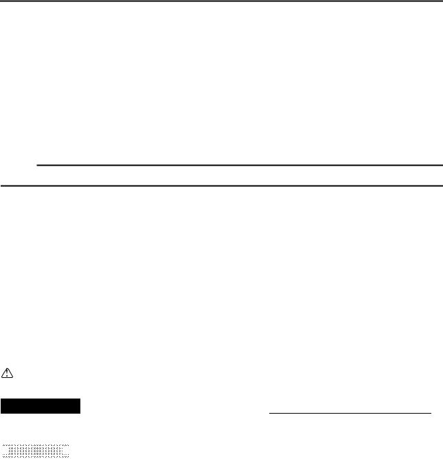
EAS00002
NOTICE
This manual was produced by the Yamaha Motor Company, Ltd. primarily for use by Yamaha dealers and their qualified mechanics. It is not possible to include all the knowledge of a mechanic in one manual. Therefore, anyone who uses this book to perform maintenance and repairs on Yamaha vehicles should have a basic understanding of mechanics and the techniques to repair these types of vehicles. Repair and maintenance work attempted by anyone without this knowledge is likely to render the vehicle unsafe and unfit for use.
Yamaha Motor Company, Ltd. is continually striving to improve all of its models. Modifications and significant changes in specifications or procedures will be forwarded to all authorized Yamaha dealers and will appear in future editions of this manual where applicable.
NOTE:
Designs and specifications are subject to change without notice.
EAS00004
IMPORTANT MANUAL INFORMATION
Particularly important information is distinguished in this manual by the following.
The Safety Alert Symbol means ATTENTION! BECOME ALERT! YOUR SAFETY IS INVOLVED!
 WARNING Failure to follow WARNING instructions could result in severe injury or death to
the motorcycle operator, a bystander or a person checking or repairing the motorcycle.

 CAUTION:
 A CAUTION indicates special precautions that must be taken to avoid damage to the motorcycle.
NOTE: A NOTE provides key information to make procedures easier or clearer.

EAS00007
HOW TO USE THIS MANUAL
This manual is intended as a handy, easy-to-read reference book for the mechanic. Comprehensive explanations of all installation, removal, disassembly, assembly, repair and check procedures are laid out with the individual steps in sequential order.
1 The manual is divided into chapters. An abbreviation and symbol in the upper right corner of each page indicate the current chapter.
Refer to “SYMBOLS”.
2 Each chapter is divided into sections. The current section title is shown at the top of each page, except in chapter 3 (“PERIODIC CHECKS AND ADJUSTMENTS”), where the sub-section title(s) appears.
3Sub-section titles appear in smaller print than the section title.
4To help identify parts and clarify procedure steps, there are exploded diagrams at the start of each removal and disassembly section.
5Numbers are given in the order of the jobs in the exploded diagram. A circled number indicates a disassembly step.
6Symbols indicate parts to be lubricated or replaced. Refer to “SYMBOLS”.
7A job instruction chart accompanies the exploded diagram, providing the order of jobs, names of parts, notes in jobs, etc.
8Jobs requiring more information (such as special tools and technical data) are described sequentially.
|
1 |
2 |
|||
|
GEN |
SPEC |
|||
|
INFO |
||||
|
3 |
4 |
|||
|
CHK |
CHAS |
|||
|
ADJ |
||||
|
5 |
6 |
|||
|
ENG |
COOL |
|||
|
7 |
8 |
|||
|
FI |
ELEC |
– |
+ |
|
|
9 |
0 |
|||
|
TRBL |
||||
|
SHTG |
||||
|
A |
B |
|||
|
C |
D |
|||
|
T |
||||
|
. |
||||
|
R |
||||
|
. |
||||
|
E |
F |
G |
||
|
H |
I |
J |
||
|
E |
G |
M |
||
|
K |
L |
M |
||
|
B |
LS |
M |
||
|
N |
O |
|||
|
LT |
New |
|||
EAS00008
SYMBOLS
The following symbols are not relevant to every vehicle.
Symbols 1 to 9 indicate the subject of each chapter.
1 General information
2Specifications
3Periodic checks and adjustments
4Chassis
5Engine
6Cooling system
7Fuel injection system
8Electrical system
9Troubleshooting
Symbols 0 to G indicate the following.
0 Serviceable with engine mounted A Filling fluid
BLubricant
CSpecial tool
DTightening torque
EWear limit, clearance
FEngine speed
GElectrical data
Symbols H to M in the exploded diagrams indicate the types of lubricants and lubrication points.
H Engine oil
I Gear oil
J Molybdenum disulfide oil
K Wheel bearing grease
L Lithium soap base grease
M Molybdenum disulfide grease
Symbols N to O in the exploded diagrams indicate the following.
N Apply locking agent (LOCTITE®)
O Replace the part
EAS00012
TABLE OF CONTENTS
|
GENERAL INFORMATION |
GEN |
1 |
|
|
INFO |
|||
|
SPECIFICATIONS |
SPEC |
2 |
|
|
PERIODIC CHECKS AND |
CHK |
3 |
|
|
ADJUSTMENTS |
|||
|
ADJ |
|||
|
CHASSIS |
CHAS |
4 |
|
|
ENGINE |
ENG |
5 |
|
|
COOLING SYSTEM |
COOL |
6 |
|
FUEL INJECTION SYSTEM
FI 7
– +
ELECTRICAL SYSTEM
ELEC 8
|
TROUBLESHOOTING |
||
|
TRBL |
9 |
|
|
SHTG |
INFOGEN 1

|
GEN |
||||
|
INFO |
||||
|
CHAPTER 1 |
||||
GENERAL INFORMATION |
||||
|
MOTORCYCLE IDENTIFICATION………………………………………………………… |
1-1 |
|||
|
VEHICLE IDENTIFICATION NUMBER …………………………………………….. |
1-1 |
|||
|
MODEL CODE ……………………………………………………………………………… |
1-1 |
|||
|
FEATURES………………………………………………………………………………………… |
1-2 |
|||
|
OUTLINE ……………………………………………………………………………………… |
1-2 |
|||
|
FI SYSTEM…………………………………………………………………………………… |
1-3 |
|||
|
COMPONENTS…………………………………………………………………………….. |
1-5 |
|||
|
FUEL INJECTION SYSTEM………………………………………………………….. |
1-17 |
|||
|
THREE-WAY CATALYTIC CONVERTER SYSTEM…………………………. |
1-26 |
|||
|
AIR INDUCTION SYSTEM……………………………………………………………. |
1-30 |
|||
|
COMPONENTS…………………………………………………………………………… |
1-31 |
|||
|
IMPORTANT INFORMATION …………………………………………………………….. |
1-35 |
|||
|
PREPARATION FOR REMOVAL AND DISASSEMBLY……………………. |
1-35 |
|||
|
REPLACEMENT PARTS………………………………………………………………. |
1-35 |
|||
|
GASKETS, OIL SEALS AND O-RINGS ………………………………………….. |
1-35 |
|||
|
LOCK WASHERS/PLATES AND COTTER PINS …………………………….. |
1-36 |
|||
|
BEARINGS AND OIL SEALS ………………………………………………………… |
1-36 |
|||
|
CIRCLIPS …………………………………………………………………………………… |
1-36 |
|||
|
CHECKING THE CONNECTIONS…………………………………………………. |
1-37 |
|||
|
SPECIAL TOOLS ……………………………………………………………………………… |
1-38 |
![]()
GEN INFO
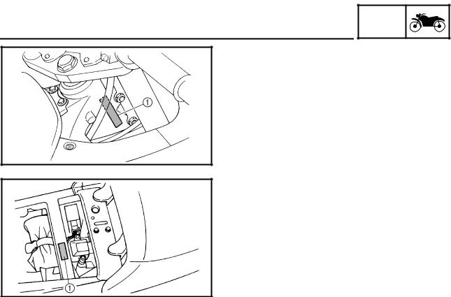
GEN
MOTORCYCLE IDENTIFICATION INFO
EAS00014
GENERAL INFORMATION
MOTORCYCLE IDENTIFICATION
EAS00017
VEHICLE IDENTIFICATION NUMBER
The vehicle identification number 1 is stamped into the right side of the steering head pipe.
EAS00018
MODEL CODE
The model code label 1 is affixed to the frame. This information will be needed to order spare parts.
1 — 1
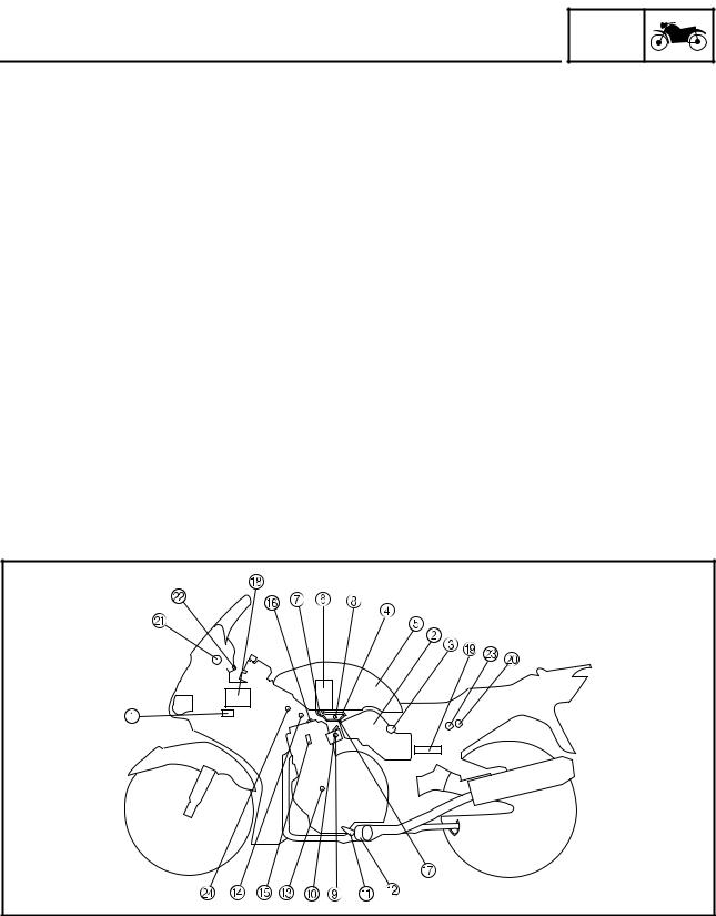
FEATURES
FEATURES
OUTLINE
GEN INFO
The main function of a fuel supply system is to provide fuel to the combustion chamber at the optimum air-fuel ratio in accordance with the engine operating conditions and the atmospheric temperature.
In the conventional carburetor system, the air-fuel ratio of the mixture that is supplied to the combustion chamber is created by the volume of the intake air and the fuel that is metered by the jet that is used in the respective chamber.
Despite the same volume of intake air, the fuel volume requirement varies by the engine operating conditions, such as acceleration, deceleration, or operating under a heavy load. Carburetors that meter the fuel through the use of jets have been provided with various auxiliary devices, so that an optimum air-fuel ratio can be achieved to accommodate the constant changes in the operating conditions of the engine.
As the requirements for the engine to deliver more performance and cleaner exhaust gases increase, it becomes necessary to control the air-fuel ratio in a more precise and finely tuned manner. To accommodate this need, this model has adopted an electronically controlled fuel injection (FI) system, in place of the conventional carburetor system. This system can achieve an optimum air-fuel ratio required by the engine at all times by using a microprocessor that regulates the fuel injection volume according to the engine operating conditions detected by various sensors.
The adoption of the FI system has resulted in a highly precise fuel supply, improved engine response, better fuel economy, and reduced exhaust emissions. Furthermore, the air induction system (AI system) has been placed under computer control together with the FI system in order to realize cleaner exhaust gases.
|
1 Ignition coil |
8 Intake air pressure |
E Spark plug |
L Engine trouble warn- |
|
2 Air filter case |
sensor |
F Cylinder identifica- |
ing light |
|
3 Intake temperature |
9 Throttle position sensor |
tion sensor |
M Lean angle cut-off |
|
sensor |
0 Fuel injector |
G Pressure regulator |
switch |
|
4 Fuel delivery hose |
A O2 sensor |
H Battery |
N Air cut-off valve |
|
5 Fuel tank |
B Catalytic converter |
I ECU |
|
|
6 Fuel pump |
C Crankshaft position |
J Atmospheric pressure |
|
|
7 Fuel return hose |
sensor |
sensor |
|
|
D Coolant temperature |
K Fuel injection system |
||
|
sensor |
relay |
1 — 2
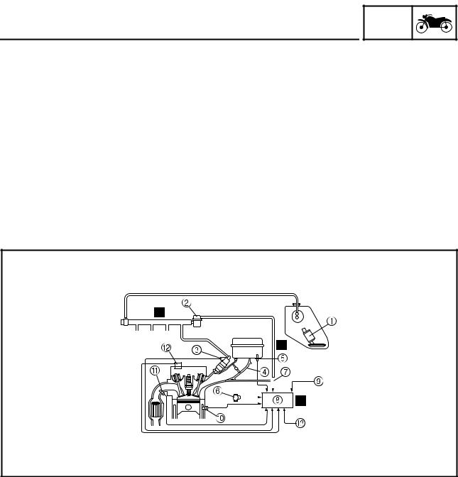
The fuel pump delivers fuel to the injector via the fuel filter. The pressure regulator maintains the fuel pressure that is applied to the injector at only 2.55 kg/cm2 higher than the intake manifold pressure. Accordingly, when the energizing signal from the ECU energizes the injector, the fuel passage opens, causing the fuel to be injected into the intake manifold only during the time the passage remains open. Therefore, the longer the length of time the injector is energized (injection duration), the greater the volume of fuel that is supplied. Conversely, the shorter the length of time the injector is energized (injection duration), the lesser the volume of fuel that is supplied.
The injection duration and the injection timing are controlled by the ECU. Signals that are input from the throttle position sensor, crankshaft position sensor, intake air pressure sensor, atmospheric pressure sensor, intake temperature sensor, coolant temperature sensor, and O2 sensor enable the ECU to determine the injection duration. The injection timing is determined through the signals from the crankshaft position sensor and the cylinder identification sensor. As a result, the volume of fuel that is required by the engine can be supplied at all times in accordance with the driving conditions.
Illustration is for reference only.
#4 #3 #2 #1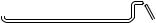
|
1 Fuel pump |
È Fuel system |
||||||||||||
|
6 Throttle position sen- |
0 Coolant temperature |
||||||||||||
|
2 Pressure regulator |
sor |
sensor |
É Air system |
||||||||||
|
3 Fuel injector |
7 Intake air pressure |
A O2 sensor |
Ê Control system |
||||||||||
|
4 Throttle body |
sensor |
B Cylinder identification |
|||||||||||
|
5 Intake temperature |
8 ECU |
sensor |
|||||||||||
|
sensor |
9 Atmospheric pressure |
C Crankshaft position |
|||||||||||
|
sensor |
sensor |
1 — 3

FEATURES
Fuel control block
The fuel control block consists of the following main components:
GEN INFO
|
Component |
Function |
|
|
Control block |
ECU |
Total FI system control |
|
Throttle body |
Air volume control |
|
|
Pressure regulator |
Fuel pressure detection |
|
|
Sensor block |
Intake air pressure sensor |
Intake air pressure detection |
|
Atmospheric pressure sensor |
Atmospheric pressure detection |
|
|
Coolant temperature sensor |
Coolant temperature detection |
|
|
Intake temperature sensor |
Intake temperature detection |
|
|
Throttle position sensor |
Throttle angle detection |
|
|
O2 sensor |
Gas emission O2 concentration detection |
|
|
Cylinder identification sensor |
Reference position detection |
|
|
Crankshaft position sensor |
Crankshaft position detection and engine |
|
|
RPM detection |
||
|
Speed sensor |
Speed detection |
|
|
Actuator block |
Injector |
Fuel injection |
|
Fuel pump |
Fuel feed |
|
|
Air Induction system, air cut valve |
Induction of secondary air |
|
An FI warning light is provided on meter panel.
1 — 4
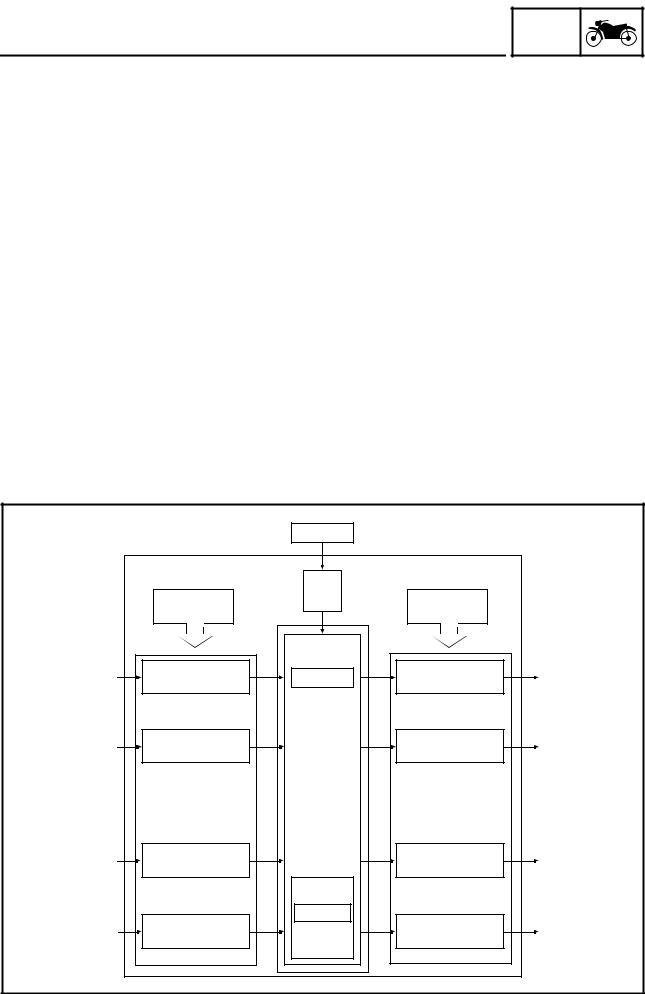
FEATURES
COMPONENTS
ECU (Electronic Control Unit)
GEN INFO
The ECU is mounted underneath the seat, below the toolbox. The main functions of the ECU are ignition control, fuel control, self-diagnosis, and load control.
•ECU’s internal construction and functions
The main components and functions of the ECU can be broadly divided into the following four items:
A.Power supply circuit
The power supply circuit obtains power from the battery (12 V) to supply the power (5 V) that is required for operating the ECU.
B.Input interface circuits
The input interface circuits convert the signals output by all the sensors into digital signals, which can be processed by the CPU, and input them into the CPU.
C.CPU (Central Processing Unit)
The CPU determines the condition of the sensors in accordance with the level of the signal that is output by the respective sensor. Then, the signals are temporarily stored on the RAM in the CPU. Based on those stored signals and the basic processing program on the ROM, the CPU calculates the fuel injection duration, injection timing, and ignition timing, and then sends control commands to the respective output interface circuits.
D.Output interface circuits
The output interface circuits convert the control signals output by the CPU into actuating signals for the respective actuators in order to actuate them. They also output commands to the indicator and relay output circuits as needed.
|
ECU |
Battery |
||||
|
Power |
|||||
|
Input |
supply |
Output |
|||
|
circuit |
|||||
|
interface circuit |
interface circuit |
||||
|
Hall sensor |
Waveform |
CPU |
Injector drive |
Injector |
|
|
shaping circuit |
output circuit |
||||
|
signal |
|||||
|
(for cylinder |
|||||
|
identification) |
|||||
|
Pickup coil signal |
Waveform |
Ignition output circuit |
Ignition coil |
||
|
shaping circuit |
|||||
|
(for identifying the |
|||||
|
crankshaft position) |
|||||
|
Switches |
Digital input circuit |
Lamp drive |
Indicating lamp |
||
|
output circuit |
|||||
|
RAM/ROM |
|||||
|
A/D converter |
MEMORY |
Relay drive |
|||
|
Sensors |
Relay |
||||
|
input circuit |
output circuit |
||||
|
1 — 5 |

GEN
FEATURES INFO
•Ignition control
The ignition control function of the ECU controls the ignition timing and the duration of ignition energizing. The ignition timing control uses the signals from the throttle position sensor (to detect the angle of the throttle), and the crankshaft position sensor and speed sensor (to detect the speed of the engine). This control establishes an ignition timing that suits the operating condition of the engine through compensations made to the basic ignition timing control map. The ignition energizing duration control establishes the energizing duration to suit the operating conditions by calculating the energizing duration in accordance with the signal received from the crankshaft position sensor and the battery voltage.
•Fuel control
The fuel control function of the ECU controls the injection timing and injection duration. The injection timing control controls the injection timing during the starting of the engine and the injection timing during the normal operation of the engine, based on the signals received from the crankshaft position sensor and the cylinder identification sensor. The injection duration control determines the duration of injection based on the signals received from the atmospheric pressure sensors, temperature sensors, and the position sensors, to which compensations are made to suit various conditions such as the weather, atmospheric pressure, starting, acceleration, and deceleration.
•Load control
The ECU effects load control in the following manner:
1.Stopping the fuel pump and injectors when the motorcycle overturns
The ECU turns OFF the fuel injection system relay when the lean angle cut-off switch is tripped.
2.Operating the headlight illumination relay
On the model for Europe, the ECU causes the headlight relay 2 to output a constant ON signal, provided that the main switch is ON. On the model for Australia, the ECU controls the headlight relay 2 in accordance with the engine speed as required by the daytime illumination specification.
3.Operating the radiator fan motor in accordance with the coolant temperature
The ECU controls the radiator fan motor relay ON/OFF in accordance with the coolant temperature.
4.Operating the AI system solenoid valve
The ECU controls the energizing of the solenoid valve in accordance with the driving conditions.
•Self-diagnosis function
The ECU is equipped with a self-diagnosis function to ensure that the engine control system is operating normally. The ECU mode functions include a diagnosis mode in addition to the normal mode.
Normal mode
• To check for any blown bulbs, this mode illuminates a warning light while the main switch is turned ON, and while the starter switch is being pressed.
• If the starting disable warning is activated, this mode alerts the rider by blinking the warning light while the start switch is being pressed.
• If a malfunction occurs in the system, this mode provides an appropriate substitute characteristic operation, and alerts the rider of the malfunction by illuminating a warning light. After the engine is stopped, this mode displays a fault code on the clock LCD.
Diagnosis mode
• In this mode, a diagnostic code is input into the ECU through the operation of the operating switch on the meter, and the ECU displays the values output by the sensors or actuates the actuators in accordance with the diagnostic code. Whether the system is operating normally can be checked by observing the illumination of the warning light, the values displayed on the meter, or the actuating state of the actuators.
1 — 6
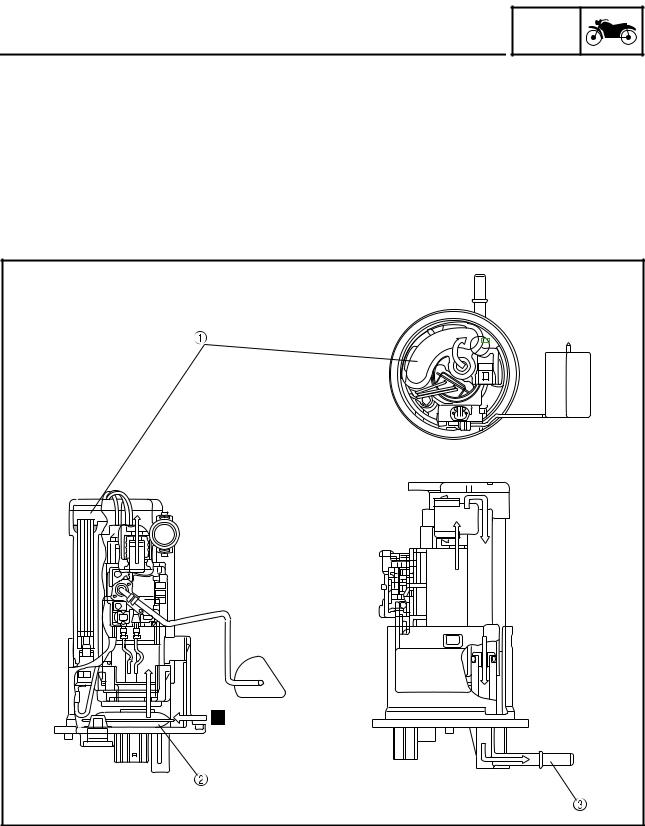
The fuel pump, which is mounted in the fuel tank, draws the fuel directly from the tank and pumps it to the injector.
A filter that is provided in the fuel pump prevents any debris in the fuel tank from entering the fuel system downstream of the pump.
The pump consists of a pump unit, electric motor, filter, and valves.
The pump unit is a Wesco type rotary pump that is connected to the motor shaft.
A relief valve is provided to prevent the fuel pressure from rising abnormally if the fuel hose becomes clogged. This valve opens when the fuel pressure at the discharge outlet reaches between 440 and 640 kpa, and returns the fuel to the fuel tank.
1 Fuel filter
2 Fuel inlet strainer
3 Outlet
È Fuel
1 — 7
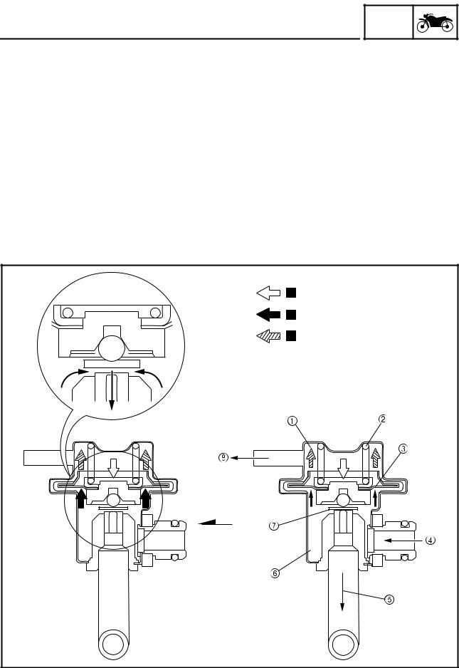
FEATURES
Pressure regulator
GEN INFO
It regulates the fuel pressure that is applied to the injectors that are provided in the cylinders in order to maintain a constant pressure difference with the pressure in the intake manifold.
The fuel that is delivered by the fuel pump fills the fuel chamber through the fuel inlet of the regulator and exerts pressure on the diaphragm in the direction for opening the valve.
A spring that is provided in the spring chamber exerts pressure on the diaphragm in the direction for closing the valve, in contrast to the pressure of the fuel. Thus, the valve cannot open unless the fuel pressure overcomes the spring force.
An intake vacuum is applied to the spring chamber via a pipe. When the pressure of the fuel exceeds the sum of the intake vacuum and the spring force, the valve that is integrated with the diaphragm opens, allowing the fuel to return from the fuel outlet to the fuel tank, via the fuel return hose.
As a result, because the intake vacuum fluctuates in accordance with the changes in the operating conditions in contrast to the constant volume of fuel supplied by the pump, the valve opening/closing pressure also changes to regulate the return fuel volume. Thus, the difference between the fuel pressure and the intake manifold pressure remains constant at a prescribed pressure.
|
1 Spring chamber |
4 Fuel inlet |
7 Valve |
È Spring pressure |
|
2 Spring |
5 Fuel outlet |
8 Intake manifold vac- |
É Fuel pressure |
|
3 Diaphragm |
6 Fuel chamber |
uum pressure |
Ê Vacuum pressure |
1 — 8
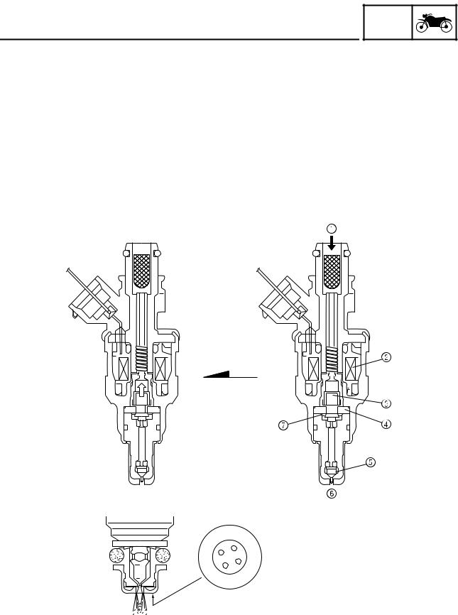
Upon receiving injection signals from the ECU, the fuel injector injects fuel. In the normal state, the core is pressed downward by the force of the spring, as illustrated. The needle that is integrated with the bottom of the core keeps the fuel passage closed.
When the current flows to the coil in accordance with the signal from the ECU, the core is drawn upward, allowing the flange that is integrated with the needle to move to the spacer. Since the distance of the movement of the needle is thus kept constant, the opening area of the fuel passage also becomes constant. Because the pressure difference of the fuel to the intake manifold pressure is kept constant by the pressure regulator, the fuel volume varies in proportion to the length of time the coil is energized. The injector that has been recently adopted has a four-hole type injection orifice that enhances the atomization of fuel and improves combustion efficiency.
|
1 Fuel |
5 Needle |
||||||||||||||||||||||||||
|
2 Coil |
6 Inject |
||||||||||||||||||||||||||
|
3 Core |
7 Flange |
||||||||||||||||||||||||||
|
4 Spacer |
1 — 9
![]()
FEATURES
Crankshaft position sensor
GEN INFO
The crankshaft position sensor uses the signals of the pickup coil that is mounted on the right side of the crankshaft. When the rotation of the pickup rotor that is attached to the crankshaft causes the projections on the rotor to pass by the pickup coil, an electromotive force is generated in the coil. The voltage of this force is then input into the ECU, which calculates the position of the crankshaft and the speed of the engine. The ignition timing is then determined in accordance with the calculated data, in order to determine the corresponding injection timing. Based on the changes in the time intervals of the signals generated by the pickup coil, the ECU calculates the ignition timing advance to suit the operating conditions. The injection timing is also advanced in accordance with the ignition timing in order to supply fuel to the engine at an optimal timing.
|
F7T556 |
5 |
|||
|
J |
||||
|
5˚ |
W |
|||
|
180˚ |
180˚ |
180˚ |
180˚ |
1 Pickup rotor
È Direction of rotation
É #1 cylinder compression stroke, 5° BTDC Ê Pickup signal
Ë Trigger pole
1 — 10

FEATURES
Cylinder identification sensor
GEN INFO
The cylinder identification sensor is mounted on the exhaust head cover of the #4 cylinder. When the exhaust cam of the #4 cylinder rotates and the lift of the cam passes by the sensor, the sensor generates a signal and sends it to the ECU. Based on this signal and the signal from the crankshaft position sensor, the ECU then actuates the injector of the cylinder that is currently in order to supply fuel.
 180˚
180˚ 
 180˚
180˚ 
 180˚
180˚ 
 180˚
180˚
#1 
#2
#4
#3
|
1 Cylinder identification |
È Cam lift |
Ë Cylinder firing order |
Î Exhaust |
|
sensor |
É Crankshaft position |
Ì #4 cam lobe onto |
Ï Injection |
|
2 Cam |
sensor signal |
exhaust camshaft |
Ð Intake |
|
Ê Cylinder identification |
Í Combustion |
Ñ Compression |
|
|
sensor signal |
Ò Ignition |
1 — 11
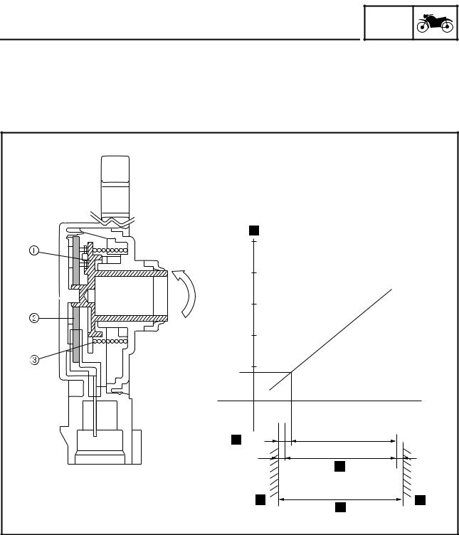
FEATURES
Throttle position sensor
GEN INFO
The throttle position sensor measures the intake air volume by detecting the position of the throttle valve. It detects the mechanical angle of the throttle valve through the positional relationship between the moving contact that moves in unison with the throttle shaft and the resistor board. In actual operation, the ECU supplies 5 V power to both ends of the resistor board and the voltage that is output by the throttle position sensor is used to determine the angle of the throttle valve.
|
50 |
|||
|
40 |
|||
|
30 |
|||
|
20 |
|||
|
10 |
|||
|
0.68 V |
|||
|
10° |
95° |
||
|
100° |
|||
|
5° |
5° |
||
|
110° |
|
1 Moving contact |
È Output voltage |
|
2 Resistor board |
É Idling output position |
|
3 Spring |
Ê Mechanical stopper |
|
Ë Mechanical stopper |
ÌEffective electrical angle
ÍSensor operating angle
1 — 12
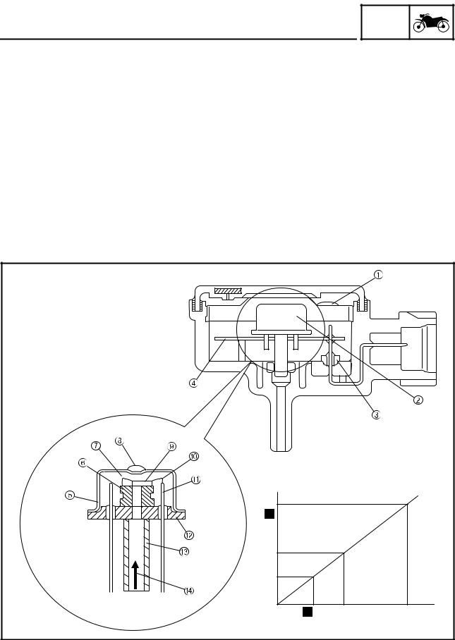
FEATURES
Intake air pressure sensor and atmospheric pressure sensor
GEN INFO
•Intake air pressure sensor
The intake air pressure sensor is used for measuring the intake air volume. The intake air volume of every intake stroke is proportionate to the intake air pressure. Therefore, the intake air volume can be measured by measuring the intake air pressure. The intake air pressure sensor converts the measured intake air pressure into electrical signals and sends those signals to the ECU. When the intake air pressure is introduced into the sensor unit, which contains a vacuum chamber on one side of the silicon diaphragm, the silicon chip that is mounted on the silicon diaphragm converts the intake air pressure into electrical signals. Then, an integrated circuit (IC) amplifies and adjusts the signals and makes temperature compensations, in order to generate electrical signals that are proportionate to the pressure.
•Atmospheric pressure sensor
The atmospheric pressure sensor is used for making compensations to the changes in the air density caused by the changes in the atmospheric pressure (particularly at high altitudes). The operating principle and function of the atmospheric pressure sensor are the same as those of the aforementioned intake air pressure sensor.
|
1 EMI shield |
6 Silicon diaphragm |
A Lead pin |
È Output voltage |
|
2 Sensor unit |
7 Vacuum chamber |
B Stem |
É Input pressure |
|
3 Through condenser |
8 Solder |
C Pressure induction pipe |
|
|
4 Hybrid IC |
9 Silicon chip |
D Atmospheric pressure, |
|
|
5 Cap |
0 Gold wire |
intake air pressure |
1 — 13
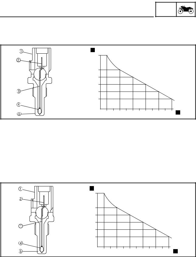
FEATURES
Coolant temperature sensor
GEN INFO
The signals from the coolant temperature sensor are used primarily for making fuel volume compensations during starting and warm-up. The coolant temperature sensor converts the temperature of the coolant into electrical signals and sends them to the ECU.
15.5
|
0.322 |
|||||||
|
-20 |
0 |
20 |
40 |
60 |
80 |
||
|
1 Connector |
3 Tube |
5 Holder |
È Resistance kΩ |
||||
|
2 Terminal |
4 Thermistor |
É Temperature °C |
Intake temperature sensor
The intake temperature sensor corrects the deviation of the air-fuel mixture that is associated with the changes in the intake air density, which are created by the changes in the intake air temperature that occur due to atmospheric temperatures. This sensor uses a semi-conductor thermistor that has a large resistance at low temperatures and a small resistance at high temperatures. The thermistor converts the temperature-dependent changes in resistance into electrical resistance values, which are then input into the ECU.
6.0
0.34
|
-20 |
0 |
20 |
40 |
60 |
80 |
|
1 Connector |
È Resistance kΩ |
|
2 Terminal |
É Temperature °C |
3Tube
4Thermistor
5Holder
1 — 14
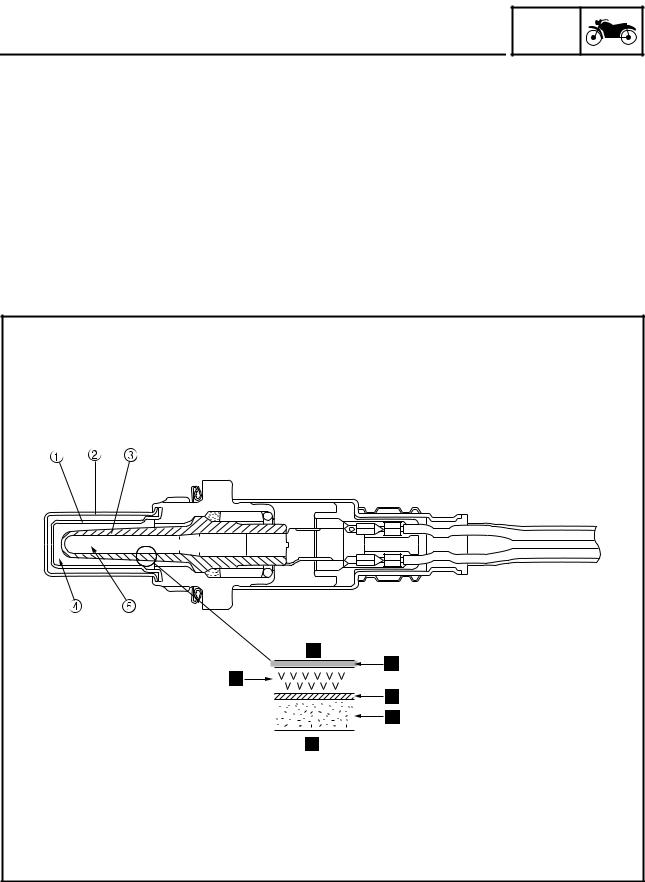
The O2 sensor has been adopted to enable the catalyst to function at a high degree of efficiency by maintaining the air-fuel mixture near the stoichiometric ratio (14.7:1). This sensor, which is a zirconia type, utilizes the oxygen ion conductivity of the solid electrolyte for detecting the oxygen concentration levels. In actual operation, a zirconia tube made of solid electrolyte is exposed in the exhaust gas, so that the exterior of the zirconia tube is in contact with the exhaust gas and the interior is in contact with the atmosphere whose oxygen concentration level is known. When a difference in the oxygen concentration level is created between the outside and the inside of the zirconia tube, the oxygen ion passes through the zirconia element and generates an electromotive force. The electromotive force increases when the oxygen concentration level is low (rich air-fuel ratio) and the electromotive force decreases when the oxygen concentration level is high (lean air-fuel ratio). As electromotive force is generated in accordance with the concentration of the exhaust gas, the resultant voltage is input into the ECU in order to correct the duration of the injection of fuel.
|
1 Inner cover |
4 Exhaust gas |
È Atmosphere |
Ë Outer electrode |
|
2 Outer cover |
5 Atmosphere |
É Inner electrode |
Ì Porous ceramic layer |
|
3 Zirconia tube |
Ê Zirconia element |
Í Exhaust gas |
1 — 15
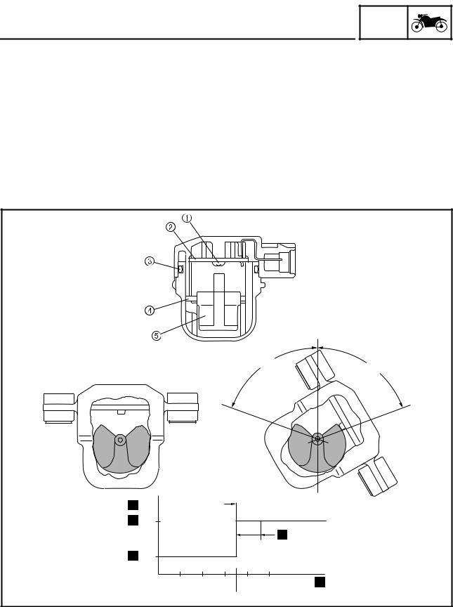
FEATURES
Lean angle cut-off switch
GEN INFO
The lean angle cut-off switch stops the supply of fuel to the engine in case the motorcycle overturns. When the motorcycle is in the normal state, the cut-off switch outputs a constant voltage of approximately 1.0 V (low level). When the motorcycle tilts, the float in the switch tilts in proportion to the tilt of the motorcycle. However, the voltage output to the ECU remains unchanged at the low level. When the tilt of the motorcycle exceeds 70 degrees (according to the tilt of the float), the signal from the sensor increases to approximately 4.0 V (high level). When the ECU receives the high-level voltage, it determines that the motorcycle has overturned, and stops the delivery of fuel to the engine by turning OFF the fuel injection system relay that powers the fuel pump and the injectors. Once the cut-off switch is tripped, the ECU maintains this state; therefore, even if the motorcycle has recovered its upright position, this state will not be canceled unless the main switch is turned OFF, and then turned back ON.
|
° |
70 |
|
70 |
|
|
° |
|
|
V |
|
|
4.0 |
|
|
1.0 |
|
|
20° 40° 60° 80° |
|
|
70° |
|
1 Thyristor |
È Output voltage |
|
2 IC unit |
É High level |
|
3 O-ring |
Ê Low level |
|
4 Shaft |
Ë Cut-off switch tilt angle |
|
5 Float |
Ì Fuel injection system |
|
relay OFF |
1 — 16
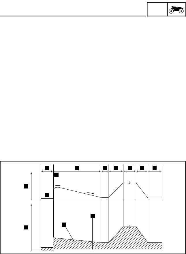
FEATURES
FUEL INJECTION SYSTEM
Operation and control
GEN INFO
The fuel injection timing, injection duration, ignition timing, and the coil energizing duration are controlled by the ECU. To determine the basic injection timing, the ECU calculates the intake air volume through the signals from the intake air pressure sensor, throttle position sensor, cylinder identification sensor, and crankshaft position sensor.
Furthermore, the ECU calculates the final injection timing by adding the following compensations to the aforementioned basic injection duration: those obtained from the state of acceleration, as well as those based on the signals from various sensors such as the coolant temperature, intake temperature, atmospheric, and exhaust pipe oxygen concentration level. At the same time, the ECU assesses the crankshaft position through the signals from the cylinder identification sensor and the crankshaft position sensor. Then, when the ECU determines that it is time to inject fuel, it sends an injection command to the injectors. Furthermore, the ECU also controls the length of time the coil is energized by calculating the ignition timing and the coil energizing duration based on the signals from these sensors.
Determining the basic injection duration
The intake air volume determines the basic injection duration. In order to operate the engine in an optimal condition, it is necessary to supply fuel at an air-fuel ratio that corresponds appropriately to the volume of intake air that is constantly changing, and to ignite it an appropriate timing. The ECU controls the basic injection duration based on the intake air volume and engine speed data.
Detection of intake air volume
The intake air volume is detected primarily through the signals from the throttle position sensor and the intake air pressure sensor. The intake air volume is determined in accordance with the signals from the atmospheric pressure sensor, intake temperature sensor, and the engine speed data.
Composition of basic injection duration
|
È RPM |
Ë Warm-up |
Î Constant |
Ñ After start |
|
É Injection duration |
Ì Idle |
Ï Deceleration |
Ò Basic injection dura- |
|
Ê Cranking |
Í Acceleration |
Ð Start |
tion |
|
Ó Voltage compensation |
|||
|
duration |
1 — 17
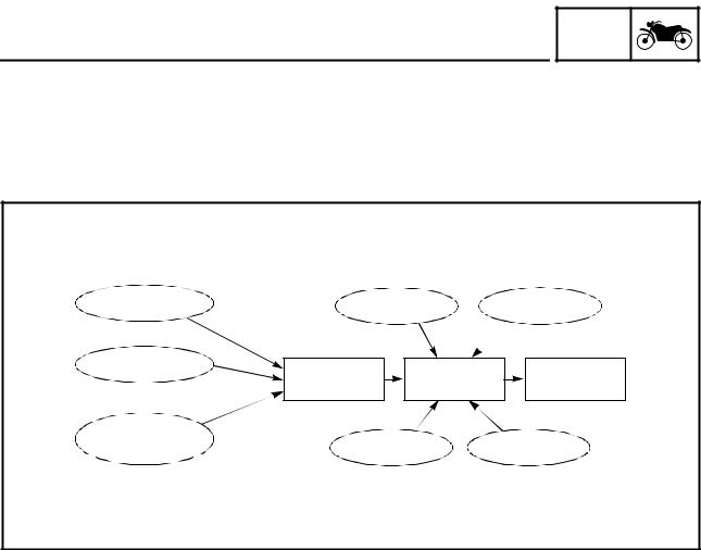
FEATURES
Determining the final injection duration
GEN INFO
The intake air volume determines the basic injection duration. However, at a given intake air volume, the volume of fuel that is required varies by the engine operating conditions such as acceleration or deceleration, or by weather conditions. This system uses various sensors to precisely check these conditions, applies compensations to the basic injection duration, and determines the final injection duration based on the operating condition of the engine.
|
Intake air pressure |
Atmospheric |
Battery voltage |
|
|
pressure |
|||
|
Engine rpm |
Basic injection |
Injection |
|
|
quantity |
Compensation |
command |
|
|
Degree of |
|||
|
opening of |
Water |
Intake air |
|
|
throttle |
temperature |
temperature |
The fuel is cut off under conditions that do not require fuel, in order to stop the injection.
1 — 18
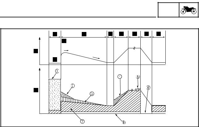
FEATURES
Composition of final injection duration
GEN INFO
|
1 Injection at start *1 |
6 Fuel cut-off |
È RPM |
Ð Start |
|
2 After-start enrichment |
Deceleration compen- |
É Injection duration |
Ñ After start |
|
*2 |
sation *5 |
Ê Cranking |
|
|
3 Warm-up enrichment |
7 Basic injection dura- |
Ë Warm-up |
|
|
*3 |
tion |
Ì Idle |
|
|
4 Acceleration compen- |
8 Voltage compensation |
Í Acceleration |
|
|
sation *5 |
duration |
Î Constant |
|
|
5 Oxygen feedback *6 |
Ï Deceleration |
Reactive injection duration:
A lag is created between the time the ECU outputs a fuel injection signal to the injector and the time the injector actually opens. Therefore, the ECU calculates this lag in advance before sending the actuation signal to the injector. The battery voltage determines the reactive injection duration.
•High voltage → short reactive injection duration
•Low voltage → long reactive injection duration
LIST OF FUEL INJECTION COMPENSATIONS
|
Compensation item |
Check item |
Sensor used |
|
Starting injection *1 |
Coolant temperature |
Coolant temperature sensor |
|
After-start injection: |
||
|
After-start enrichment *2 |
Coolant temperature |
Coolant temperature sensor |
|
Warm-up enrichment *3 |
Coolant temperature |
Coolant temperature sensor |
|
Intake temperature compensation *4 |
Intake temperature |
Intake temperature sensor |
|
Acceleration compensation/decelera- |
Intake air pressure |
Intake air pressure sensor |
|
tion compensation *5 |
||
|
Throttle position |
Throttle position sensor |
|
|
Coolant temperature |
Coolant temperature sensor |
|
|
Air-fuel ratio feedback compensation |
Exhaust gas residual oxy- |
O2 sensor |
|
*6 |
gen concentration |
|
1 — 19
![]()
FEATURES
Fuel control during normal driving
GEN INFO
In synchronous injection during normal driving, fuel is injected on a cylinder-by-cylinder basis when all of the conditions below are met:
1 Other than the stop mode
2 Cylinder identification completed
3 Other than overrun
To determine the injection timing, the ECU calculates the injection timing through the use of the 3D control map provided in the ECU, which is based on the throttle position and the engine speed. The injection duration is based on the basic injection duration (obtained through the throttle position, intake air pressure, and engine speed) to which injection duration compensation (based on the signals from various sensors such as the intake temperature sensor, atmospheric pressure sensor, and O2 sensor) is added to determine the final injection duration. As a result, fuel is supplied to the cylinders.
• Normal synchronous injection
|
#2 |
#4 |
#3 |
#1 |
#2 |
#4 |
#3 |
#1 |
|
1 Injector #1 |
4 Injector #4 |
É Crankshaft identifica- Ë Stop |
|
2 Injector #2 |
È Cylinder identification |
tion signal |
|
3 Injector #3 |
signal |
Ê Injection |
• Fuel injection control during normal driving
|
È #1 cylinder fuel injec- |
É Basic injection dura- |
Ê Various types of fuel |
||||||||
|
tion timing |
tion |
injection duration com- |
||||||||
|
pensations |
ËSynchronous injection duration (final injection duration)
1 — 20

FEATURES
Fuel injection compensation control
GEN INFO
• Starting injection control
The coolant temperature is used for determining the injection duration in order to ensure proper start ability. To suit the engine’s operating conditions, the starting injection duration is determined by applying a starting compensation coefficient to the basic injection duration, which forms the basis of the injection duration.
(Starting injection duration = basic injection duration × injection compensation coefficient)
During starting, injection cylinder control is effected together with injection duration compensation. To effect injection cylinder control, the injectors of all the cylinders inject fuel only once immediately upon receiving the signals from the sensors during the cranking of the engine. This is called asynchronous injection, in contrast to synchronous injection, which is a normal cylinder injection that is effected on a cylinder-by-cylinder basis.
After the asynchronous injection is completed, and until the ECU receives signals from the cylinder identification sensor, the injectors are actuated in pairs in sync with the signals from the crankshaft position sensor: cylinders #1 and 4, and cylinders #2 and 3. Controlling both the injection duration and the injection cylinders in this manner enables a precise supply of fuel in accordance with the starting conditions of the engine.
• Starting injection duration
|
1 Basic injection dura- |
È Injection duration |
|
tion |
É Coolant temperature |
|
2 After-start compensa- |
Ê Extended duration |
|
tion injection duration |
3Low
4High
1 — 21

FEATURES
• Starting cylinder control
GEN INFO
#1/4
|
1 Injectors #1,4 |
È Cylinder identification |
Ê Injection |
|
2 Injectors #2,3 |
sensor |
Ë Stop |
|
3 Starting asynchro- |
É Crankshaft position |
Ì Synchronous injection |
|
nous injection |
sensor |
|
|
4 Group injection |
• After-start enrichment
After-start enrichment provides enrichment compensation during a prescribed duration following the starting (firing) of the engine. While the amount of fuel enrichment is determined by the after-start enrichment coefficient, the coefficient varies by the coolant temperature. Although the coolant temperature determines the initial starting enrichment coefficient, the coefficient subsequently changes in accordance with the damping factor. The enrichment ratio is the highest immediately after the engine is started, and diminishes gradually. The enrichment of fuel in this manner ensures a stable engine operation immediately after the engine is started.
Changes in compensation coefficient and compensation injection duration
|
Engine speed |
Long |
After-start enrichment |
|
|
Stopped |
Injection |
Basic injection |
|
|
duration |
|||
|
Cranking |
duration |
||
|
Initial starting enrichment |
Short |
||
|
coefficient |
Starting enrichment coefficient |
Duration |
|
|
(determined by coolant |
|||
|
temperature) |
|||
|
Changes in compensation coefficient |
Compensation injection |
||
|
duration |
|||
|
1 — 22 |

GEN
FEATURES INFO
• Warm-up enrichment
When the coolant temperature is low, a warm-up coefficient is applied in accordance with the signals from the coolant temperature sensor in order to effect fuel enrichment. Because the coolant temperature determines the coefficient, the coefficient changes with the fluctuations in the coolant temperature. The coefficient increases with the decrease in the coolant temperature, and decreases with the increase in the coolant temperature. The ratio of fuel enrichment also changes with the changes in the coefficient.
Changes in compensation coefficient and compensation injection duration
|
Large |
|||
|
Enrichment |
coefficient |
Long |
|
|
Short |
|||
|
Small |
1.0 |
||
|
60 |
(˚C) |
||
Coolant temperature
Low 
 High
High
|
Injection |
Warm-up enrichment |
|
duration |
|
|
Basic injection duration |
|
|
Duration |
|
Changes in compensation coefficient |
Compensation injection duration |
1 — 23

GEN
FEATURES INFO
• Acceleration enrichment
Acceleration enrichment is provided in accordance with the signals from the throttle position sensor. As the rider operates the accelerator to accelerate the motorcycle from a constant speed, the throttle position sensor actuates in unison with the accelerator. The ECU interprets that acceleration has taken place through the throttle position sensor signal and executes acceleration enrichment. The enrichment volume is determined by the acceleration enrichment coefficient. The coefficient increases with the changes in the throttle position sensor, which also increases the actual enrichment volume. The enrichment volume is executed in accordance with the acceleration enrichment coefficient when the movement of the throttle position sensor has met the acceleration condition as defined by the ECU. Thereafter, the enrichment volume is regulated by the coefficient that changes in accordance with the damping rate.
(Acceleration injection duration = basic injection duration × acceleration compensation coefficient)
Changes in compensation coefficient and compensation injection duration
|
Changes in acceleration |
||
|
compensation coefficient |
||
|
Large |
Acceleration enrichment volume |
|
|
Changes in |
Long |
|
|
throttle position |
Injection |
|
|
sensor angle |
||
|
duration |
||
|
Small |
Short |
Basic injection duration |
|
Duration |
Duration |
|
|
Starting of acceleration |
||
|
Starting of acceleration |
||
|
Compensation injection duration |
1 — 24

GEN
FEATURES INFO
• Deceleration control
Deceleration control is effected in accordance with the signals from the throttle position sensor. As the rider operates the accelerator to decelerate the motorcycle that is in motion, the throttle position sensor acutates in unison with the accelerator. When the engine speed is greater than a prescribed value with the throttle fully closed (thus applying engine braking), the ECU executes a deceleration fuel cut-off. The injection of fuel to all the cylinders is stopped when fuel cut-off control is executed, thus improving fuel economy.
È Engine speed É Duration
Ê Fuel cut-off control (stopping fuel injection) Ë Basic injection duration
Ì Basic injection duration
• Over-revving control
This function effects fuel cut-off control when the engine speed becomes greater than the prescribed value. The fuel cut-off control regulates the engine speed by stopping the injection of fuel into two cylinders when the engine speed becomes greater than the specified value. If the engine speed increases further, this control stops the injection of fuel to all the cylinders. Thus, the overrevving control effects fuel cut-off control in two stages.
1 — 25

FEATURES
THREE-WAY CATALYTIC CONVERTER SYSTEM
System outline
GEN INFO
This is a highly efficient exhaust gas cleaning system that effects air-fuel control through a joint effort by the FI system, O2 sensor, and the three-way catalytic converter system. By effecting comprehensive control of the air-fuel ratio in this manner, this system reduces the CO, HC, and NOx in the exhaust gases.
The FI system controls the mixture to an optimal air-fuel ratio (basic air-fuel ratio) that matches the operating condition of the engine in order to realize an ideal combustion.
Furthermore, an O2 sensor that detects the concentration of oxygen that remains in the exhaust gas is provided in the exhaust pipe for the purpose of maximizing the performance of the three-way catalytic converter and to clean the exhaust gas at a high degree of efficiency. Based on this data, the ECU applies more precise compensation to the basic air-fuel ratio, in order to maintain the mixture in the vicinity of the stoichiometric air-fuel ratio of 14.7:1.
Through the joint effort of these control systems, the exhaust gas is cleaned in a highly efficient manner without sacrificing engine performance.
Three-way catalytic converter system diagram
|
1 Ignition coil |
5 Intake air pressure |
9 Cylinder identification |
B Igniter |
|
2 Injector |
sensor |
sensor |
C Atmospheric pressure |
|
3 Intake temperature |
6 Crankshaft position |
0 Spark plug |
sensor |
|
sensor |
sensor |
A ECU |
D Catalytic converter |
|
4 Throttle position sen- |
7 O2 sensor |
||
|
sor |
8 Coolant temperature |
||
|
sensor |
1 — 26

FEATURES
Functions of components
GEN INFO
|
Equipment |
Functions |
Main components |
|||
|
Catalyzer (honeycomb |
Simultaneously reduces |
• Catalytic converter |
|||
|
type) |
CO, HC, and NOx emis- |
• Catalyst case |
|||
|
sions. |
|||||
|
catalytic |
|||||
|
system |
Air-fuel compensation |
Reduces CO, HC, and NOx |
• O2 sensor |
||
|
equipment |
emissions. The catalyst pri- |
• ECU |
|||
|
marily cleans the exhaust |
|||||
|
gases in order to ensure |
|||||
|
Three-way |
converter |
||||
|
the stoichiometric air-fuel |
|||||
|
ratio. |
|||||
|
Fuel cut-off equipment |
Reduces CO and HC emis- |
• Throttle position sensor |
|||
|
sions, improves fuel econ- |
• ECU |
||||
|
omy, and cuts off fuel |
|||||
|
during deceleration. |
|||||
Catalyst
Because the conditions in which NOx is generated are directly opposed to those of CO and HC, there is a limit to the extent to which the concentration levels of these harmful elements can be reduced in the combustion stage. Hence, the function of the catalyst is to clean the exhaust gas at a high degree of efficiency by removing CO, HC, and NOx in the exhaust stage.
This model has adopted a monolith type metallic catalyst with a honeycomb construction, which achieves a low exhaust resistance through the large surface area of the catalyst body (with a high level of cleaning efficiency).
Catalytic substances consisting of precious metals such as platinum and rhodium are adhered to the wall surface of these honeycomb cells, which are enclosed in the exhaust pipe. As the exhaust gas comes in contact with these catalytic substances, the chemical reactions of oxidation and reduction advance in order to clean the exhaust gas.
•The CO and HC oxidize with the oxidation function of platinum, and are converted into harmless carbon dioxide (CO2) and water (H2O), resulting in cleaner exhaust gases.
|
CO + 1/2 O2 |
CO2 |
||
|
HC + O2 |
CO2 + H2O |
||
•The NOx is reduced by the reduction function of rhodium, which converts NOx into harmless nitrogen (N2) and oxygen (O2), resulting in cleaner exhaust gases.
To clean the exhaust gases at a high rate of efficiency through the maximization of these catalytic capacities, it is necessary to maintain and control the mixture in the vicinity of the stoichiometric airfuel ratio of (14.7:1) at all times. As a means of maintaining the stoichiometric ratio, this system has adopted an O2 feedback compensation method that uses an O2 sensor, which will be described in the next section.
1 — 27

GEN
FEATURES INFO
Large amounts of both CO and HC are generated when the mixture is rich (as indicated by insufficient O2 region A). Conversely, large amounts of NOx are generated when the mixture is lean (as indicated by excessive O2 region B). Under these conflicting characteristics, the system maintains the mixture within an extremely narrow range C of stoichiometric ratio (14.7:1). As a result, the function of the catalyst is maximized, making it possible to clean the exhaust gases at a high degree of efficiency.
Conv. (%)
|
100 |
|||||||||||
|
NOx |
|||||||||||
|
80 |
|||||||||||
|
60 |
|||||||||||
|
40 |
HC |
||||||||||
|
20 |
CO |
||||||||||
|
14.7 |
|||||||||||
|
0 |
|||||||||||
|
13 |
13.5 |
14 |
14.5 |
15 |
15.5 |
16 |
1 — 28

FEATURES
Air-fuel ratio compensation equipment
GEN INFO
An O2 sensor is provided in the exhaust pipe upstream of the catalyst, to enable the catalyst to operate at a high degree of efficiency. The O2 sensor detects the level of concentration of the oxygen remaining in the exhaust gases.
A high level of oxygen concentration signifies a lean air-fuel mixture, and when the O2 sensor detects this condition, it inputs a lean signal into the ECU. Conversely, when the level of oxygen concentration is low, the O2 sensor inputs a rich signal into the ECU.
The ECU system applies minute corrections to these signals so that the injection volume (the duration of the current applied to the injectors) comes to be within the vicinity of the stoichiometric ratio. Thus, the system is designed to maximize the cleaning function of the catalyst.
Feedback compensation circuit
Illustration is for reference only.
Prolongs the duration of the current applied to the injectors
Injection duration correction circuit
Shortens the duration of the current applied to the injectors
Basic injection duration circuit
Signal from various sensors
Injector
Air-fuel ratio judged as
lean
Lean signal
|
Air-fuel ratio |
Rich signal |
|
|
judged as |
||
|
rich |
È The ECU determines the basic injection volume based on the signals that are input from various sensors and regulates the duration of the current applied to the injectors.
É Current is applied to the injectors, enabling them to inject fuel. Ê The engine undergoes combustion and exhaust.
ËThe O2 sensor detects the level of oxygen concentration in the exhaust gases, and outputs a lean or rich air-fuel ratio signal in accordance with the detected data.
ÌIn accordance with the signals from the O2 sensor, the ECU applies minute corrections to the basic injection duration, determines the subsequent injection volume, and provides instructions to the injectors.
The above processes are repeated in order to maintain the mixture at the stoichiometric ratio.
1 — 29
![]()
FEATURES
AIR INDUCTION SYSTEM
GEN INFO
The air induction system (AI system) introduces fresh air into the exhaust port in order to burn the unburned gas (which is present in the exhaust gas) in the exhaust pipe. The burning of the unburned gases in this manner enhances the efficiency of the catalyst and results in cleaner exhaust gases.
The AI system takes a portion of the air from the air cleaner, sends it to the reed valve via the air cut-off valve, and introduces it directly into the exhaust port through the reed valve.
The air cut-off valve is controlled by the signals from the ECU in accordance with the combustion conditions. Ordinarily, the air cut-off valve opens to allow the air to flow during idle and closes to cut off the flow when the motorcycle is being driven. However, if the coolant temperature is below the specified value, the air cut-off valve remains open and allows the air to flow into the exhaust pipe until the temperature becomes higher than the specified value.
The reed valve is provided on the cylinder head cover above the cylinders, and sends air to the exhaust pipe through the inside of the cylinder head.
1Air cut-off valve
2Reed valve
3Exhaust port
4Resonator
1 — 30

1.Air cut-off valve
The air cut-off valve consists of a plunger that is mounted inside the core of a solenoid coil, and a valve at the end of the plunger for opening and closing the air passage. Due to the force of a spring, the valve is in constant contact with valve block A, and thus keeps the air passage open. As a result, the air from the air cleaner passes through the air passage and flows into the reed valves of the cylinders. When the current flows to the solenoid coil in accordance with a signal from the ECU, the plunger in the core becomes attracted towards the coil. When this attraction force overcomes the pressure of the spring, the valve is pulled in along with the plunger, comes in contact with valve block B, and closes the air passage. The ECU controls the operation of the air cut-off valve so that it operates in an optimal condition to suit the driving conditions.
|
1 Valve block A |
3 Spring |
5 Core |
È To reed valve |
|
2 Valve |
4 Coil |
6 Valve block B |
É From air cleaner |
1 — 31

FEATURES
Instrument panel
GEN INFO
Function indication
The indications of the self-diagnosis function can be checked and inspection operations can be performed through the use of the multi-function meter on the instrument panel.
Based on the signals received from the sensors, the ECU inputs the signals into the multi-function meter. Then, the conditions of the sensors appear on the clock and trip/odometer display of the multi-function meter.
1. ECU transmission data and meter display
|
Mode |
ECU transmission data |
Meter indication |
Display description |
|
|
Vehicle speed |
Trip meter |
4 digits including decimals |
||
|
Common to all |
Engine warning |
Indicator lamp |
ON/OFF |
|
|
indicator lamp |
||||
|
modes |
||||
|
Self-diagnostic fault |
Clock LCD |
Shows trouble code in numbers |
||
|
code |
||||
|
Normal mode |
Coolant temperature |
Coolant tempera- |
Coolant temperature |
|
|
ture meter LCD |
||||
|
CO/DIAG mode |
CO/DIAG selection |
Clock LCD |
Shows CO or DIAG in letters |
|
|
selection |
||||
|
CO adjustment |
Clock LCD |
Shows adjustment cylinder No. |
||
|
CO adjustment |
cylinder No. |
in numbers |
||
|
mode |
||||
|
CO adjustment volume |
Trip LCD |
Shows adjustment volume in |
||
|
numbers |
||||
|
Diagnostic code |
Clock LCD |
Shows diagnostic code in num- |
||
|
DIAG mode |
bers |
|||
|
Diagnosis sensor value |
Trip LCD |
Shows data for sensors |
||
Note: If the exchange of data between the ECU and the meters is abnormal, the clock LCD shows error “Er-1~4”. The clock LCD reverts to showing the time after the error has been corrected.
|
180 |
||
|
200 |
||
|
220 |
||
|
240 |
||
|
260 |
F |
|
|
280 |
||
|
Km/h |
L |
H |
|
TRIP |
km |
|
|
TRIP |
mile |
|
|
km |
||
|
E ODO |
mile |
|
|
SELECT |
RESET |
|
1 Fuel meter |
3 Coolant temperature |
5 TRIP/ODO meter |
8 Engine trouble warn- |
|
2 Clock |
meter |
6 RESET button |
ing light |
|
4 TRIP meter |
7 SELECT button |
9 Oil level warning light |
1 — 32

FEATURES
2. DIAG and CO mode inspection and adjustment (multi-function meter)
GEN INFO
Mode Selection (Make sure to disconnect the coupler from the fuel pump.)
CO/DIAG mode
1.While keeping both the SELECT and RESET buttons pressed, turn “ON” the
main switch. Keep the buttons pressed for 8 seconds or more.
*All the segments are “OFF” except the clock and the trip LCD.
*“DIAG” appears on the clock LCD.
Switching between CO adjustment mode and DIAG mode
1.Press the SELECT button in order to switch the display to “CO” or “DIAG”.
2.Simultaneously press the SELECT and RESET buttons for 2 seconds or more to select an item.
CO adjustment mode
Enables the adjustment of CO for any of the four cylinders by pressing the SELECT and RESET buttons.
1. Adjustment cylinder selection
*Press the SELECT and RESET buttons to select the cylinder.
*The adjustment cylinder appears on the clock LCD.
*RESET button = decrement
*SELECT button = increment
*Execute the selection of the cylinder by simultaneously pressing the SELECT and RESET
buttons for approximately 2 seconds. 2. CO adjustment
*After selecting the adjustment cylinder, change the adjustment volume by pressing the SELECT and RESET buttons.
*The adjustment volume appears on the trip LCD.
*RESET button = decrement
*SELECT button = increment
*The selection is executed upon releasing the finger from the switch.
*Simultaneously press the SELECT and RESET buttons to return to the cylinder selection.
Cancel the mode by turning “OFF” the main switch.
Normal mode
Turn “ON” the main switch.
*The self-diagnostic function starts a system check.
System normal Normal meter display
Malfunction detection A fault code number appears on the clock LCD.
The engine trouble warning light illuminates.
(The engine cannot be started in this mode.)
Diagnosis mode
Enables the verification of the operation of the actuator and various sensors.
* Turn the engine stop switch to “OFF”. (Turn it “ON” when the diagnostic code is 09 or 03.)
1. Press the SELECT and RESET buttons to select the Diagnosis mode.
*RESET button = decrement
*SELECT button = increment
*A diagnostic code number appears on the clock LCD.
2. Checking the operation of the actuator
*Turn “ON” the engine stop switch to start the operation.
3. Checking the operation of various sensors
*The condition of the operation appears on the TRIP LCD.
1 — 33

GEN
FEATURES INFO
180
|
200 |
||
|
220 |
||
|
240 |
||
|
260 |
F |
|
|
280 |
||
|
Km/h |
L |
H |
|
TRIP |
km |
|
|
TRIP |
mile |
|
|
km |
||
|
E ODO |
mile |
|
|
SELECT |
RESET |
1Clock
2TRIP meter
3RESET button
4SELECT button
5Engine trouble warning light
1 — 34

GEN
IMPORTANT INFORMATION INFO
EAS00020
IMPORTANT INFORMATION
PREPARATION FOR REMOVAL AND
DISASSEMBLY
1.Before removal and disassembly, remove all dirt, mud, dust and foreign material.
2.Use only the proper tools and cleaning equipment. Refer to the “SPECIAL TOOLS”.
3.When disassembling, always keep mated parts together. This includes gears, cylinders, pistons and other parts that have been “mated” through normal wear. Mated parts must always be reused or replaced as an assembly.
4.During disassembly, clean all of the parts and place them in trays in the order of disassembly. This will speed up assembly and allow for the correct installation of all parts.
5.Keep all parts away from any source of fire.
EAS00021
REPLACEMENT PARTS
Use only genuine Yamaha parts for all replacements. Use oil and grease recommended by Yamaha for all lubrication jobs. Other brands may be similar in function and appearance, but inferior in quality.
EAS00022
GASKETS, OIL SEALS AND O-RINGS
1.When overhauling the engine, replace all gaskets, seals and O-rings. All gasket surfaces, oil seal lips and O-rings must be cleaned.
2.During reassembly, properly oil all mating parts and bearings and lubricate the oil seal lips with grease.
1 — 35

GEN
IMPORTANT INFORMATION INFO
EAS00023
LOCK WASHERS/PLATES AND COTTER PINS
After removal, replace all lock washers/plates 1 and cotter pins. After the bolt or nut has been tightened to specification, bend the lock tabs along a flat of the bolt or nut.
EAS00024
BEARINGS AND OIL SEALS
Install bearings and oil seals so that the manufacturer’s marks or numbers are visible. When installing oil seals, lubricate the oil seal lips with a light coat of lithium soap base grease. Oil bearings liberally when installing, if appropriate.
1 Oil seal
 CAUTION:
@
Do not spin the bearing with compressed air because this will damage the bearing surfaces.
1 Bearing
EAS00025
CIRCLIPS
Before reassembly, check all circlips carefully and replace damaged or distorted circlips. Always replace piston pin clips after one use. When installing a circlip 1, make sure the sharp-edged corner 2 is positioned opposite the thrust 3 that the circlip receives.
4 Shaft
1 — 36

IMPORTANT INFORMATION
EAS00026
GEN INFO
CHECKING THE CONNECTIONS
Check the leads, couplers, and connectors for stains, rust, moisture, etc.
1.Disconnect:
• lead
• coupler
• connector
2.Check:
•lead
•coupler
•connector
Moisture → Dry with an air blower. Rust/stains → Connect and disconnect sev-
eral times.
3. Check:
•all connections
Loose connection → Connect properly.
NOTE:
If the pin 1 on the terminal is flattened, bend it up.
4. Connect:
•lead
•coupler
•connector
NOTE:
Make sure all connections are tight.
5. Check:
• continuity (with the pocket tester)
Pocket tester 90890-03112
NOTE:
•If there is no continuity, clean the terminals.
•When checking the wire harness, perform steps (1) to (3).
•As a quick remedy, use a contact revitalizer available at most part stores.
1 — 37

SPECIAL TOOLS
EAS00027
SPECIAL TOOLS
GEN INFO
The following special tools are necessary for complete and accurate tune-up and assembly. Use only the appropriate special tools as this will help prevent damage caused by the use of inappropriate tools or improvised techniques. Special tools, part numbers or both may differ depending on the country.
When placing an order, refer to the list provided below to avoid any mistakes.
|
Tool No. |
Tool name/Function |
Illustration |
|
Slide hammer bolt |
||
|
Bolt |
Weight |
|
|
90890-01083 |
||
|
Weight |
||
|
90890-01084 |
These tools are needed to remove the |
|
|
main axle assembly. |
||
|
Coupling gear/middle shaft tool |
||
|
90890-01229 |
||
|
This tool is needed when removing or |
||
|
installing the coupling gear nut. |
||
|
Final gear backlash band |
||
|
90890-01230 |
||
|
This tool is needed when measuring the |
||
|
final gear backlash. |
||
|
Rotor holding tool |
||
|
90890-01235 |
This tool is needed to hold the camshaft |
|
|
sprocket when loosen or tighten the |
||
|
camshaft sprocket bolts. |
||
|
Piston pin puller set |
||
|
90890-01304 |
||
|
This tool is used to remove the piston |
||
|
pin. |
||
|
Radiator cap tester |
||
|
Tester |
Radiator cap tester adapter |
|
|
90890-01325 |
||
|
Adapter |
||
|
90890-01352 |
This tester and its adapter are needed |
|
|
for checking the cooling system. |
||
|
Flywheel puller |
||
|
Puller |
||
|
90890-01362 |
||
|
This tool is needed to remove the rotor. |
||
1 — 38

|
SPECIAL TOOLS |
GEN |
||||
|
INFO |
|||||
|
Tool No. |
Tool name/Function |
Illustration |
|||
|
Steering nut wrench |
|||||
|
90890-01403 |
|||||
|
This tool is needed to loosen and |
|||||
|
tighten the steering stem ring nut. |
|||||
|
Oil filter wrench |
|||||
|
90890-01426 |
|||||
|
This tool is needed to remove and |
|||||
|
install the oil filter. |
|||||
|
Fork seal driver |
|||||
|
90890-01442 |
This tool is needed when installing the |
||||
|
slide metal, oil seal and dust seal into |
|||||
|
the fork. |
|||||
|
Gear lash measurement tool |
|||||
|
90890-01467 |
|||||
|
This tool is needed when measuring the |
|||||
|
middle gear backlash. |
|||||
|
Damper rod holder |
|||||
|
90890-01447 |
This tool is needed to hold the damper |
||||
|
rod assembly when loosen or tighten |
|||||
|
the damper rod assembly bolt. |
|||||
|
Pivot shaft wrench |
|||||
|
90890-01471 |
|||||
|
This tool is needed to loosen or tighten |
|||||
|
the spacer bolt. |
|||||
|
Sheave holder |
|||||
|
90890-01701 |
This tool is needed to hold the rotor |
||||
|
when removing or installing the rotor |
|||||
|
bolt, starter clutch and pickup coil rotor |
|||||
|
bolt. |
|||||
|
Compression gauge |
|||||
|
Gauge |
Compression gauge adapter |
||||
|
90890-03081 |
|||||
|
Adapter |
|||||
|
90890-04136 |
These tools are needed to measure |
||||
|
engine compression. |
|||||
1 — 39
 Loading…

Руководство по эксплуатации и техническому обслуживанию мотоциклов Yamaha FJR1300A.
- Издательство: Yamaha Motor Co., Ltd.
- Год издания: 2010
- Страниц: 105
- Формат: PDF
- Размер: 6,0 Mb

Руководство по эксплуатации и техническому обслуживанию мотоциклов Yamaha FJR1300AS.
- Издательство: Yamaha Motor Co., Ltd.
- Год издания: 2009
- Страниц: 105
- Формат: PDF
- Размер: 4,1 Mb

Сборник руководств на английском языке по эксплуатации и техническому обслуживанию мотоциклов Yamaha моделей FJR13AD(C)/AEV(C)/AEY(C)/AV(C)/AX(C)/AZ(C).
- Издательство: Yamaha Motor Co., Ltd.
- Год издания: 2005-2012
- Страниц: —
- Формат: PDF
- Размер: 23,8 Mb

Сборник руководств на английском языке по эксплуатации и техническому обслуживанию мотоциклов Yamaha моделей FJR1300/A/AP/AS(C)/AT(C)/N/R/RC/S(C)/T(C).
- Издательство: Yamaha Motor Co., Ltd.
- Год издания: 2001-2010
- Страниц: —
- Формат: PDF
- Размер: 64,7 Mb
Руководство на английском языке по ремонту мотоциклов Yamaha моделей FJR1300 и FJR1300N 2001 года выпуска.
- Издательство: Yamaha Motor Co., Ltd.
- Год издания: —
- Страниц: 617
- Формат: PDF
- Размер: 15,2 Mb
Руководство на английском языке по ремонту мотоциклов Yamaha моделей FJR1300A и FJR1300AV 2006 года выпуска.
- Издательство: Yamaha Motor Co., Ltd.
- Год издания: 2006
- Страниц: 586
- Формат: PDF
- Размер: 23,3 Mb
Руководство (дополнение) на английском языке по ремонту мотоциклов Yamaha моделей FJR1300, FJR1300A, FRJ1300AS и FRJ1300S 2004 года выпуска.
- Издательство: Yamaha Motor Co., Ltd.
- Год издания: 2003
- Страниц: 44
- Формат: PDF
- Размер: 1,7 Mb

Сборник руководств на английском, французском, немецком, испанском и итальянском языках по ремонту мотоциклов Yamaha моделей FJR1300, FJR1300A и др.
- Издательство: Yamaha
- Год издания: —
- Страниц: —
- Формат: ISO
- Размер: 1,7 Gb
