Загрузка…
Главы «Руководства” размещены так, чтобы облегчить изучение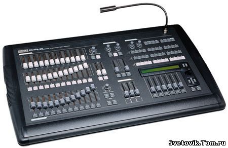
особенностей пульта STUDIO 24 SCAN CONTROL. При описании используется
простая терминология, которая в то же время остается технической. Новая
серия пультов, к которой принадлежит STUDIO 24 SCAN CONTROL была
разработана для максимального удовлетворения потребностей пользователя.
Главы 1 и 2 дают общую информацию о приборе, поэтому изложены простым
общедоступным языком. Глава 11, в которой изложены дополнительные
возможности пульта, хотя и не изложена «чисто” техническим языком, но
достаточно сложна. Описания функций и команд расположены начиная с
простейших и заканчивая самыми сложными. Даже опытным операторам
желательно прочитать «Руководство” целиком, так как часто лишь после
глубокого понимания структуры прибора можно понять все нюансы
пользования им.
#1
Опубликовано 01 октября 2014 — 15:41
Здравствуйте, нужна помощь для световика с 0 знаниями. как настроить адресацию каналов и как узнать какой прожектор на каком канале находится? пульт sgm studio 24 scan control Инструкция есть но все равно ничего не понимаю
- Наверх
#2
ALEXLIGHT2003
ALEXLIGHT2003
- Gender:Male
Опубликовано 01 октября 2014 — 15:47
С 0 Вы не запачите его( Вы в каком городе?
- Наверх
#3
alena
Опубликовано 01 октября 2014 — 15:53
в респ. коми г.Печора
- Наверх
#4
alena
Опубликовано 01 октября 2014 — 15:54
 ALEXLIGHT2003, 01 октября 2014 — 15:47, написал:
С 0 Вы не запачите его( Вы в каком городе?
я нахожусь в Респ.Коми г.Печора
- Наверх
#5
ALEXLIGHT2003
ALEXLIGHT2003
- Gender:Male
Опубликовано 01 октября 2014 — 16:22
Тогда надо искать спеца там. что у вас за приборы?
- Наверх
#6
vadim67
vadim67
- Gender:Male
- Location:Северск
Опубликовано 02 октября 2014 — 06:15
Ваш пульт может управлять 48-ю диммерными каналами и 12-ю головами(сканерами, роллерами,LED PARами) и прочей «интеллектуальной» техникой. По умолчанию первые 48 DMX каналов пульта запатчены 1:1. Т.е один фейдер управляет одним каналом. Предположим, что у Вас имеется 2 диммера по 24 канала. Ставите на одном диммере адрес 1, на другом адрес 25. коммутируете пульт с диммерами и управляете яркостью каналов. С интеллектуальными приборами посложнее. Если фонарики, которые есть у Вас имеются в библиотеке пульта, нужно их пропатчить в соотв. с кол-вом занимаемых ими каналов и кол-ва этих приборов. Если в библиотеке их нет, придется самому, по карте каналов прибора создавать профиль в самом пульте, сохранять его в библиотеке и потом уже патчить. Если у Вас уже все установлено, то через «Сетап» можно просмотреть, что и где сидит. Все это в инструкции написано, и проще, чем там не описать, если только не «вот эта херовина к вот этой фиговине». В инструкции -Диммерные каналы п 8, 8.1. DIMMER PATCH. Установка интеллектуальных приборов п8.2 UNIT PATCH. Создание нового прибора п8,5,1 CREATE NEW UNIT.
Если Вы не знаете, что такое протокол DMX512 — Гугл в помошь. Информации в свободном доступе до… много в общем. И про сам протокол и про адресацию и про использование этого протокола и про его особенности.
Если Вы не знаете, какие у Вас приборы, ищите их названия и паспорта на них, инструкции.

STUDIO_24_SCAN_CONTROL1.pdf 478,89 Кб
166 раз скачано Инструкция на Ваш пульт на русском. Вполне читабельная.
С переводом отдельных понятий, таких как Dimmer? Unit, Spot и т.д. Опять же онлайн переводчик.
По созданию шаблонов в инструкции пошагово подробно все расписано. Просто следуем пунктам. С непривычки и от незнания — таки да, гемор, но куда деваться. Захочешь светить — не так раскорячишься.
Если вообще ничего не понятно, постарайтесь более четко сформулировать Ваши вопросы, будем покопаться.
- Наверх
#7
alena
Опубликовано 02 октября 2014 — 12:31
vadim67, 02 октября 2014 — 06:15, написал:
Ваш пульт может управлять 48-ю диммерными каналами и 12-ю головами(сканерами, роллерами,LED PARами) и прочей «интеллектуальной» техникой. По умолчанию первые 48 DMX каналов пульта запатчены 1:1. Т.е один фейдер управляет одним каналом. Предположим, что у Вас имеется 2 диммера по 24 канала. Ставите на одном диммере адрес 1, на другом адрес 25. коммутируете пульт с диммерами и управляете яркостью каналов. С интеллектуальными приборами посложнее. Если фонарики, которые есть у Вас имеются в библиотеке пульта, нужно их пропатчить в соотв. с кол-вом занимаемых ими каналов и кол-ва этих приборов. Если в библиотеке их нет, придется самому, по карте каналов прибора создавать профиль в самом пульте, сохранять его в библиотеке и потом уже патчить. Если у Вас уже все установлено, то через «Сетап» можно просмотреть, что и где сидит. Все это в инструкции написано, и проще, чем там не описать, если только не «вот эта херовина к вот этой фиговине». В инструкции -Диммерные каналы п 8, 8.1. DIMMER PATCH. Установка интеллектуальных приборов п8.2 UNIT PATCH. Создание нового прибора п8,5,1 CREATE NEW UNIT.
Если Вы не знаете, что такое протокол DMX512 — Гугл в помошь. Информации в свободном доступе до… много в общем. И про сам протокол и про адресацию и про использование этого протокола и про его особенности.
Если Вы не знаете, какие у Вас приборы, ищите их названия и паспорта на них, инструкции.
 STUDIO_24_SCAN_CONTROL1.pdf Инструкция на Ваш пульт на русском. Вполне читабельная.
С переводом отдельных понятий, таких как Dimmer? Unit, Spot и т.д. Опять же онлайн переводчик.
По созданию шаблонов в инструкции пошагово подробно все расписано. Просто следуем пунктам. С непривычки и от незнания — таки да, гемор, но куда деваться. Захочешь светить — не так раскорячишься.
Если вообще ничего не понятно, постарайтесь более четко сформулировать Ваши вопросы, будем покопаться.
Спасибо, попробую разобраться
- Наверх
#8
straus
Опубликовано 02 октября 2014 — 14:28
alena, 01 октября 2014 — 15:41, написал:
Здравствуйте, нужна помощь для световика с 0 знаниями. как настроить адресацию каналов и как узнать какой прожектор на каком канале находится? пульт sgm studio 24 scan control Инструкция есть но все равно ничего не понимаю
Значится так. Прежде всего надо усвоить главное — осветительные приборы бывают простые и интеллектуальные. Простые умеют только ярче-тусклее, и занимают один канал. Интеллектуальные умеют яркость, поворот, наклон, цвет и т.д. Причём в одних приборах цвет может изменяться одним каналом, а в других может делаться смешиванием нескольких цветов. Поэтому интеллектуальные приборы (головы, сканеры, колорчейнджеры) занимают несколько каналов. В настройках интеллектуальных приборов устанавливается самый младший канал, на который он откликается, остальные обычно идут подряд. Например прибор занимает 8 каналов, а на нём выставлен канал 33 — значит он будет отзываться разными функциями на каналы с 33-го по 40-й. Соответственно на следующем приборе нужно выставить 41-й канал, и будет он отзываться на каналы 41-48. И т.д.
Теперь про пульты. В пульте нужно указать прежде всего, на каких каналах приборы простые, а на каких — интеллектуальные. Обычно в пультах забита база приборов, так что нужно указать только модель прибора и его стартовый канал. В пультах попроще нужно вручную указать для каждого прибора количество занимаемых каналов и их назначение. В обоих случаях если занимаемые каналы налезут друг на друга (например прибор занимает каналы 41-48, а следующему прибору мы укажем стартовый канал 47) — пульт сообщит об ошибке.
Это основное. Если это усвоить — дальше всё просто. Единственная разница — программирование. Для одноканальных приборов обычно забиваются полные световые картины (включаем такие-то приборы вводя нужные фейдеры), а для интеллектуальных — изменения световых картин (например передвигаем лучи и меняем цвет, остальные параметры оставляем теми-же). Ну то есть, если мы какой-то параметр не изменили — он автоматически перейдёт в новую картину, соответственно указываем только те параметры, которые меняем. И кроме того, если мы погасили луч — параметры цвета, трафаретов и прочего нас уже не волнуют до следующего открытия луча. Благодаря этому программирование получается быстрее.
По поводу «как узнать, какой прожектор на каком канале» — все интеллектуальные приборы имеют переключатели, или кнопки и цифровые индикаторы, которыми задаётся стартовый канал (остальные, как мы помним, идут за ним подряд). На диммерах для обычных прожекторов точно также. Ну а в пультах настраивается так называемая патч-таблица, в которой указывается, какой канал пульта будет в реальности управлять каким каналом какого прибора.
- Наверх
#9
DENI969
DENI969
-

- Members
-
- 1 Сообщений:
Newbie


Опубликовано 22 октября 2014 — 13:08
alena, 01 октября 2014 — 15:41, написал:
Здравствуйте, нужна помощь для световика с 0 знаниями. как настроить адресацию каналов и как узнать какой прожектор на каком канале находится? пульт sgm studio 24 scan control Инструкция есть но все равно ничего не понимаю
могу дать уроки от записи приборов через rs 232
до граба в регистры, чейзы и тд. поскольку сам работал на 12 и 24 канальной версии.
напишите на почту Snaiper969@mail.ru свой скайп, по возможности отвечу вам.
- Наверх
#10
Zoomer
Zoomer
-
- Members
-
- 1 Сообщений:
Newbie

Опубликовано 31 октября 2014 — 09:31
Желаю успехов в постижении пульта. Есть один совет по эксплуатации: блок питания пульта очень чувствителен к скачкам напряжения, поэтому не советую втыкать его во все розетки подряд. Горит на раз. При таких манипуляциях может пострадать и дисплей пульта, как у меня было например. Заказать его через дилеров можно только с Италии. Ждал 3 месяца, работал вслепую А в целом хороший пульт для театрального света.
- Наверх
#11
ERIC_164
ERIC_164
-
- Members
-
- 2 Сообщений:
Newbie

Опубликовано 07 ноября 2015 — 12:09
Добрый день. У меня токая проблема как включаю пульт все загружается и после загрузки загорается кнопка direct и пульт становится не управляемой что делать помогите
- Наверх
#12
Alien3674
Опубликовано 15 ноября 2015 — 14:30
Здравствуйте!
Такой вопрос.
По идее если не используются регистры то после выключении программы должна быть темнота? После выключения программы включается какая то ранее сохраненная программа. Складывается впечатление что программа сохранена «по умолчанию» после выключения других программ. Как изменить это?
- Наверх
-
Contents
-
Table of Contents
-
Bookmarks
Quick Links
Studio 12
scan control
scan control
professional light desk user’s manual
rel. 1.41
Related Manuals for SGM Studio 12
Summary of Contents for SGM Studio 12
-
Page 1
Studio 12 scan control scan control professional light desk user’s manual rel. 1.41… -
Page 2: General Instructions
• In the event of serious operating problems, stop using the fixture immediately and either con- tact the nearest SGM sales point for a check or contact the manufacturer directly. • Do not open the fixture — there are no user serviceable parts inside.
-
Page 3: Table Of Contents
10.2 — Creating a track 7.3 — Movement effects 10.3 — Replaying a track 7.4 — Use in Reg mode 11 — Advanced use of the Studio 12 Scan Control 7.5 — The Utilities 11.1 — Multiple units 7.5.1 — Remote lamp ignition 11.2 — Multiple scanner units…
-
Page 4: Handbook Layout
Each section is presented using the simplest possible terminology, although remaining necessa- rily technical. The new range of consoles to which the Studio 12 Scan Control belongs has been designed to ensure the utmost user-friendliness. Chapters 1 and 2 are deliberately generic and conversational and have the job of introducing the unit.
-
Page 5: Main Features
1. Studio 12 Scan Control console layout 1.1 Main Features SGM’s new Studio 12 Scan Control console is one of the results of our long experience in the manufacture of this type of control equipment, and is able to control 12 or 24 dimmer channels and 12 intelligent fixtures using up to a maximum of 36 DMX 512 serial digital signal channels.
-
Page 6: Studio 12 Scan Control’s Sections
1.3 Studio 12 Scan Control’s sections 1.3.1 — Manual presets This is the most traditional area of lighting con- manual presets soles and comprises 2 rows of 12 faders each, 8 16 32 which can be used as two 12 channel presets 1÷12…
-
Page 7: Dmx Unit Controls
1.3.4 — Masters m as t er s The Studio console has 3 masters, i.e. general level controls. The REG master controls the outputs of the memory registers, the FLASH master controls the level of the FLASH buttons and the GRAND MASTER controls the overall output level of all the channels, including the REG master.
-
Page 8: Studio 12 Connectors
1.4 Studio 12 connectors pedal smpte midi settings rs-232 audio in main 0dB mono signal in/out thru security lock in/out on/off pin out: 1 = gnd midi rs-232 2 = -dmx out 3 = +dmx out 4 = -dmx in…
-
Page 9: Disconnecting The Power Supply
1.4.7 — Disconnecting the power supply Studio consoles are powered by an AL4 switching power supply. This is fitted with a connector plug which has a small built-in locking mechanism to prevent accidental disconnection. To disconnect the power supply from the console, always grip the plug, not the cable, as shown in the diagram: Before disconnecting the power supply, always remember to switch off the console.
-
Page 10: Studio 12 Scan Control Operating Modes
In “double preset” mode, it’s possible to mix presets A and B, either manually or automatically, using MANUAL PRESET CROSS TIME (see chapter 4). Studio 12 Scan Control consoles’ channels are set to operate with channels 1 — 24 as dimmer controls.
-
Page 11
4 — Manual Preset section This section of the console is entirely manual and recognisable by its light grey fader knobs and buttons. manual presets 8 16 32 of f m ax 1÷12 manual presets cross time li nk s olo 12÷24 22 11 23 12… -
Page 12
under control. When one preset is off and the other on, pressing A and B simultaneously enables the GO func- 8 16 32 ma x tion. In this case, the crossover between the two scenes is instantaneous if the manual presets cross time potentiometer is set at 0 or OFF, otherwise it takes place in the time set, which can vary from 0 seconds to 8 minutes. -
Page 13
4.2.1 — Go function 8 16 32 m ax In this operating mode, the GO function and the are not enabled. manual presets cross time 4.2.2 — Solo function s o lo The manual zone also includes the function. When this is enabled (the relative LED is lit), the subtractive flash function is enabled. -
Page 14: Memory Pages
5 — Register Section The REGISTER section is the “heart” of 8 16 32 Studio 12 Scan Control consoles. m ax The memory registers are “containers” registers cross time g ra b p l a y holding a fixed scene, a light chase and smpte a “Scan Control”…
-
Page 15: Storing A Scene
5.3 — Storing a scene Transferring a scene prepared on the MANUAL PRESETS to a memory register is very simple. In g rab fact, operators only have to press the button and hold it down, followed by the button of the required register (from 1 to 12).
-
Page 16
MANUAL PRESETS correspond to the steps. The lit LEDs indicate the enabled steps. m us i c function allows to run the chases in sync with music. For the purpose, Studio 12 con- soles are fitted with a built-in microphone and an audio input which automatically excludes the microphone. -
Page 17: Creating And Modifying Chases
6.1 — Chase running level The first almost unique feature is that of slope having twin chase speed regulation. Two potentiometers (RATE and SLOPE) control the total length of single steps chase chase chase and the time taken to pass from one step step step step…
-
Page 18
7. DMX Unit Control Section dmx unit controls This section of the console comprises a universal control- music bkward pause store direct util setup 4 5 6 4 5 6 ler for units requiring a maximum of 36 control channels, m i n m a x m i n… -
Page 19: Direct Mode Use
4 5 6 4 5 6 m i n m a x m in ma x ra te s p eed . RATE regulates the crossover time from one scene to another in a pro- gram, while SPEED regulates the speed of the mirror or moving head and the effects set on “SOFT”…
-
Page 20: Movement Effects
7.1.1 Program elements Every Scan Control program can work on all the available parameters or just some of them. Operators can in fact decide how many SCENES make up the program (from 1 o 12), which units to use (from 1 to 12) and which of the individual fixtures’ effects are to be used. When one of the PROG buttons is pressed and held down, the following appears on the display: ————SELECT UNIT———— select active scenes/units/effects…
-
Page 21: Use In Reg Mode
SHAPE X_SCL Y_SCL SPEED ROTAT ANG static — — —— — Shapes available at present are Circle, Square, Diagonal 1, Diagonal 2, Angles, Inf.ty, Zigzag. Parameters at operators’ disposal at present are: X_SCL: scale on the X axis (from 0 to 100%) Y_SCL: scale on the Y-axis (from 0 to 100%) SPEED: speed at which the effect is run (from 0 to 255) ROTAT: direction of movement (normal or inverse)
-
Page 22: Remote Lamp Ignition
display and can be scrolled by pressing the SCROLL buttons on the right of the display. 7.5.1 Remote lamp ignition If the fixtures used allow it, this utility enables fixtures’ lamps to be switched on and off extremely easily. u til After pressing the button, scroll with the SCROLL buttons until the following appears: LAMP 1 2 3 4 5 6 7 8 9 10 11 12…
-
Page 23: Copying A Scene
Operating areas can be created as required, without being obliged to form regular shapes, as shown in the design alongside. There’s no command for resetting a operating area once it’s been set, but to do so the 4 corners are selected and the co-ordinates shown in the design alongside entered: 0.0 — 999.0 — 999.999 — 0.999.
-
Page 24: Copying A Program
7.6.2 — Copying a program To copy the contents of one program to another, press the button of the “origin” program, then s to re and (holding it down) press the button of the “target” program. 7.6.3 — Adding a Program to a Memory Register Adding a program to a Memory Register is a very simple procedure: once the program has been sto re selected and running parameters set, press the…
-
Page 25: Setup Functions
By means of the Setup menu, accessed by pressing the button, access is gained to the Studio 12 Scan Control’s numerous functions. 8.1 — Addressing light channels This function has two fundamental aims: deciding which are the DMX channels corresponding to the faders in the dimmer channel section and also carrying out multiple patches.
-
Page 26: Changing The Language Used
In the example above, unit 1 is an SGM Victory II 250, whose start address has been set at 100. Scan Control will automatically calculate the last channel required for that fixture and on the right- hand side of the display show the configuration to be set on the dip-switches on the rear of the fixture.
-
Page 27: Built-In Memory
Select ITEM — [CREATE NEW UNIT Access is gained to the library by pressing the right-hand SCROLL button. N.B. To simplify menu examples, we shall create an SGM Victory II 250 as a new fixture. 8.5.1.1 — DMX channel total This information allows Scan Control to know how many channels new units use.
-
Page 28: Internal Addressing
Enter number of LCD pages esc<- NNNNNNNNNNNN— ok-> The display will show Using the CURSOR up/down arrows (or the right-hand fader of the row under the display), opera- tors can increase the number of pages required to view all the unit’s effects on the display. Continuing with our example (the Victory II 250), 2 pages are necessary: the unit in fact has 12 channels, 4 of which are reserved for Pan and Tilt and 1 for Remote Reset, so 7 remain for the effects, which will be divided by 6 (the effects which can be allocated to each menu), thus obtai-…
-
Page 29: Standby Values
8.5.1.4 — Standby values This menu is used to set the parameters which must be sent to the fixtures when they are not involved in a scene or used manually. It’s very important to set these values, particularly when operating with fixtures fitted with discharge lamps, whose shutters have to be closed to avoid unwanted illumination, or for those with halogen lamps, for which, as well as closing the shutter, output can be lowered by dimming the light.
-
Page 30: Slope Speed
DIMMR COLOR PALET GOBOS ROT.G SHUTR <-> [DIM] EFF In this case: and then PRISM —————————— <-> [EFF] — These settings therefore indicate when the channel of the dimmer function must be considered as such (DIM) and when it must be considered as an effect (EFF). Press the left-hand SCROLL to return to the creation menu now.
-
Page 31: Unit Name
to access setting and the left-hand button to exit the function. Once OK (right-hand SCROLL) has been pressed, the effect string created in 8.5.1.2 reappears: the following menu appears: DIMMR COLOR PALET GOBOS ROT.G SHUTR <-> [HARD] HARD HARD HARD HARD HARD .
-
Page 32: Dip-Switch Configuration
to access setting and the left-hand button to exit the function. Once OK (right-hand SCROLL) has been pressed, the following menu appears: RESET OFF ON ≥ LAMP OFF [—] — — ≥ — — — ok-> . Use the CURSOR up/down arrows to set the value and the right-hand SCROLL to confirm the choice and return to the pre- vious menu.
-
Page 33: Beam Search Values
1 2 3 4 5 6 7 8 9 fig. 1 2+8+32+64=106 1 2 3 4 5 6 7 8 9 fig. 2 (pure binary) and fig. 2 (1+ binary): . Both systems are used by 2+8+32+64=106+1=107 manufacturers throughout the world and in practical terms, they differ in the fact that in the pure binary system the address has a value of 1 if the switch is at ON, whereas in the “1+binary”…
-
Page 34
132. This value will be entered in a table and can be easily reached using the controls as already explained. The use of the tables requires a more memory when adding new units to the library (see parag. 8.4). The following menu appears: Select feature to configure for esc<- VICTORY TST —[CONTROL TYPE… -
Page 35: Error Messages
PAGE_1 TOT. ITEM ITEM VALUE EFFECT_1 [13] 125 ok-> PAGE_1 TOT. ITEM ITEM VALUE EFFECT_1 [13] 145 ok-> PAGE_1 TOT. ITEM ITEM VALUE EFFECT_1 [13] 165 ok-> PAGE_1 TOT. ITEM ITEM VALUE EFFECT_1 [13] 180 ok-> PAGE_1 TOT. ITEM ITEM VALUE EFFECT_1 [13] 198 ok->…
-
Page 36: Modifying A Unit In The Library
When <OK> is pressed the error message disappear. La differente gestione della memoria per gli “Event Recording” (capitolo 10) non segnala con messaggi la mancanza di spazio: in questo caso si fermerà automaticamente la registrazione (cfr. 10.2). 8.5.3 — Modifying a unit in the library This option allows operators to modify the parameters of units already in the library.
-
Page 37: Using The Connectors
This signal is generally used in broadcasting (television productions). It’s only an input, as Studio 12 Scan Control con- soles don’t generate a signal for external use. The SMPTE signal is normally obtained using the MIDI Time Code (from a sequencer, for example) and converting it with one of the numerous devices available for this purpose.
-
Page 38: Midi In — Note On
9.3.3 — Midi IN — Program Change This MIDI function allows to change the presets a unit is equipped with. On Studio 12 consoles, transmitting this data allows to pass from one memory register to another. The range of parame- ters must be between 0 and 11.
-
Page 39: Midi In — All Channels Off
7Bh and 0h) and results in all the channels which were previously on being switched on. 9.3.5 — Midi IN — Bank Select This function allows to pass from one memory bank to another and on Studio 12 consoles is used to change memory register PAGE.
-
Page 40: Rs-232 — Register Change (A0H)
Example: switch off channel 4 = CH_OFF,3. 9.4.3 — RS-232 — All Off (A3h) This command allows to switch off all channels previously switched on with the Channel On command. There’s no operator. The command syntax is as follows: ALL_OFF Example: switch off the channels = ALL_OFF.
-
Page 41: Using ‘Event Recording
Studio 12 Scan Control consoles are able to record 12 sequences of events and reproduce them. In order to do this, a time code is required for sync purposes: for this reason, Studio 12 consoles are fitted with a socket for connection to an SMPTE signal generator.
-
Page 42: Replaying A Track
10.3 — Replaying a track To replay a recorded track, no matter in what operating mode it’s to be run in, press the PLAY button and hold it down, then (using the Memory registers’ buttons) select the required ‘track’. appendice…
-
Page 43: Advanced Use Of The Studio 12 Scan Control
There are at present no intelligent fixtures on the market requiring this number of channels: the SGM Galileo IV Live 1200 (at present the most powerful in the SGM range) in fact only uses 18. Considering that the console operates on all 512 DMX channels, it’s possible to exploit the 36 channels available by creating multiple units, i.e.
-
Page 44
Enter the string for effects more<-> DIM10 RAT10 DIM11 RAT11 DIM12 RAT12 Enter the string for effects more<-> DIM13 RAT13 DIM14 RAT14 DIM15 RAT15 • Allocation of control channels: DIM01 RAT01 DIM02 RAT02 DIM03 RAT03 <-> [ 1] DIM04 RAT04 DIM05 RAT05 DIM06 RAT06 <-> [ 7] DIM07 RAT07 DIM08 RAT08 DIM09 RAT09 <->… -
Page 45
DIM07 RAT07 DIM08 RAT08 DIM09 RAT09 <-> [DIM] EFF DIM10 RAT10 DIM11 RAT11 DIM12 RAT12 <-> [DIM] EFF DIM13 RAT13 DIM14 RAT14 DIM15 RAT15 <-> [DIM] EFF • Setting for Mirror/Head (the fixture has no moving parts): X(PAN) ≥ Y(TILT) ≥… -
Page 46: Multiple Scanner Units
Working in this way means that operators can also create multiple colourchangers, for example by setting 5 SGM Colorbasic 250 fixtures (which require 5 channels each) in a single unit. In this case, addressing must be in blocks of five.
-
Page 47
To achieve particular effects, it’s possible to “cheat” on the real identity of a fixture. Taking an SGM Colorlab 250 as an example, it can be “transformed” into a scanner with 8-bit movement: all that’s necessary is to set the channels that would be used for Pan and Tilt to the channels relative to Colour and Shutter. -
Page 48: Quick Reference
12 — Quick reference This section sums up the function buttons on the Studio 12 Scan Control and their applications. 8 16 32 of f ma x This control sets the time for the automatic crossfade between preset A and pre- manual presets cross time set B (GO function — parag.
-
Page 49
This function is used to select a page of the Memory Registers. Studio 12 Scan Control has 12 pages. mode This function allows to assign the Memory Registers’ operating mode. Operating flash modes are And, Or, Flash and Flash or Fader. -
Page 50
d i re ct This function, located in both the Light Chase Control and DMX Unit Control sections, allows to output a light chase or a scanner program (according to the section in question) inde- pendently of the Memory Registers. Light chases and scanner programs can only be created in DIRECT mode. -
Page 51
12 — Tree structure diagram of Setup functions… -
Page 52: Practical Users Guide
13 — Practical users guide The following pages contain the series of commands to use to obtain a particular condition. For convenience, the following three symbols indicate the status of the buttons’ LEDs: off ( ), on ( ) or flashing ( 13.1 — Turning on light channels 1 — set the required values using the faders of Preset A or B (or both) p se t…
-
Page 53
maste r s 4 — Set a level on the Grand Master re g f lash grand 8 16 32 of f m a x 5 — Set crossfade time manual presets cross time p set 6 — Press buttons A and B simultaneously 13.3 — Storing a Memory Register p se t 1 — Turn on preset A or B or both… -
Page 54
13.4 — Generating flashes from the light channels master s 1 — Set the Master Flash level f lash grand 1or13 2or14 2 — Press the buttons of the channels below preset B 13.5 — Generating a subtractive flash master s 1 — Set the Master Flash level f lash grand… -
Page 55: Creating A Chase
13.7 — Unlatching a light channel from the Link link 1 — Press the LINK button and hold it down 1or13 2 — Press the button of the channel to unlatch l ink 3 — Release the LINK button (the LED goes off) 13.8 — Creating a chase To create Chase 1, made up of 2 steps: direct…
-
Page 56
13.9 — Running a chase To run the Chase 1 created in 13.8 (made up of two steps): direct 1 — Press the Direct button chase 1or13 2 — Select Chase 1 by pressing cha se d irect 3 — Set the Chase output level as required step 1or13 2or14… -
Page 57
13.11 — Deleting a chase from a Memory Register To delete Chase 1 from Register 1: 1 — Press and hold down the Reg button, followed by the required Register button chase 1or13 2 — Delete the Chase by pressing 13.12 — Switching off a chase in Direct mode To switch off Chase 1: direct… -
Page 58
5 — Press the cursor Up/Down buttons to set the DMX channel the console’s physical channel has to be addressed to until the required channel appears: DMX-CH CHANNEL LIM% EQUAL ok-> [512] <—- — <DEL> 6 — Use the Left/Right cursor to go under the “DMX-CH” field and set the logic channel of the mixer which has to control channel 512 (if the values weren’t preset, selecting the logic channel automatically creates the LIM% and EQUAL “fields”: DMX-CH… -
Page 59
UNIT TYPE FROM —- 1—cod—10 [ 1]————-<DEL>TO —- ˛˛˛˛˛˛˛˛˛ 6 — Press the right-hand cursor button to set the field to be modified 7 — Use the Up/Down buttons to select the Victory II: UNIT TYPE FROM —- 1—cod—10 1 [VICTORY 2 ]<DEL> A —- ˛˛˛˛˛˛˛˛˛ 8 — Use the Left/Right buttons to select the FROM field (start address) and set the required value: UNIT TYPE… -
Page 60
13.16 — Creating a Scan Control program To create program 1, made up of 1 scene and using 1 unit: direct 1 — Press the Direct button 2 — Press and hold down the Prog button of the required program ————SELECT UNIT———— select active scenes/units/effects 3 — The following menu appears:… -
Page 61
10 — Press the button of the unit to be controlled: 11 — Set the parameters required on Unit 1. 12 — Press and hold down the Store button, followed by the button of the scene to be stored: store pause 13 — Press Pause to start the program running again 13.17 — Adding a program to a Memory Register… -
Page 62
Via Pio La Torre, 1 • 61010 TAVULLIA (PS) • ITALY • Tel. +39 0721476477 • Fax +39 0721476170 www.sgm.it • info@sgm.it…
|
|
#3 |
|
Новичок Регистрация: 18.03.2011 Сообщений: 2 Вес репутации: 0
|
Спасибо! Akser. Да я читал главу 9. Там как раз и написано что можно управлять пультом дистанционно. Вот софт меня и интересует, т.к. переходник у меня есть и к компу подключается (тоесть комп видит пульт и определяет ево именно как студию 24), но на этом все и заканчивается. На сайте разработчика есть только программа для обновления прошивки. |

|
|


КАТАЛОГ

Артикул: 117961
SGM STUDIO 24 Scan control Профессиональный пульт управления светом, DMX-512
- Описание товара
- Характеристики
- Отзывы
- Аксессуары
распечатать
Производитель: SGM
Характеристики и комплектация могут быть изменены фирмой-производителем без предварительного уведомления.
Фото и описания товара на сайте могут не точно соответствовать товару.
Описание
Описание
SGM STUDIO 24 Scan control Профессиональный пульт управления светом в протоколе DMX-512, до 512 диммерных каналов — 24/48 пресетов (фейдеров) и 24 чейза, до 12 управляемых приборов по 36 каналов — 12 програм по 12 сцен, 24 регистра, (24 страницы), 576 световых картин, редактируемая библиотека приборов, субмастера, гранд-мастер. DMX 512, MIDI, RS-232, SMPTE.