- Manuals
- Brands
- Siemens Manuals
- Control Systems
- SINUMERIK 802C
- Manual
-
Contents
-
Table of Contents
-
Bookmarks
Quick Links
Start-Up 01/2002 Edition
SINUMERIK 802C
Related Manuals for Siemens SINUMERIK 802C
Summary of Contents for Siemens SINUMERIK 802C
-
Page 1
Start-Up 01/2002 Edition SINUMERIK 802C… -
Page 3
Numerical Control System SINUMERIK 802C Installing the Control System Start–Up Installing the Drives Start–Up Update Valid for Technical Appendix Control Software Version SINUMERIK 802C Manual Machine Index 01.2002 Edition… -
Page 4
Trademarks SIMATICr, SIMATIC HMIr, SIMATIC NETr, SIROTECr, SINUMERIKr and SIMODRIVEr are registered trademarks of Siemens. Third parties using for their own purposes any other names in this document which refer to trademarks might infringe upon the rights of trademark owners. -
Page 5
The device may only be used for the cases of application, as intended by the Catalog, and only in conjunction with third–party devices and components recommended or approved by Siemens. The proper and safe operation of the product requires transport, storage and installation according to the relevant instructions and qualified operation and maintenance at the prescribed intervals. -
Page 6: Table Of Contents
2-15 Installing and removing the SINUMERIK 802C ……..
-
Page 7
7-132 Default assignment of special data for the “Manual machine” ……7-133 SINUMERIK 802C 6FC5 597–3AA20–0BP2 (01.02) -
Page 8
Table of Contents notice SINUMERIK 802C viii 6FC5 597–3AA20–0BP2 (01.02) -
Page 9: Sinumerik 802C Control System
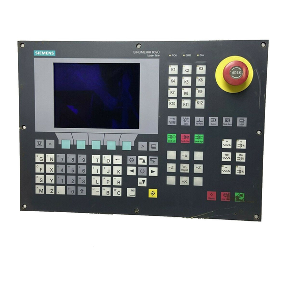
SINUMERIK 802C Control System Components of the SINUMERIK 802C What is SINUMERIK? The SINUMERIK 802C is a microprocessor–controlled numerical control system for simple machine tools with stepper motor drives . Hardware components It consists of the following hardware components: ENC: Control component for a maximum of 3 analog axes and an analog interface for a…
-
Page 10
– PLC software (Programmable Logic Control), executes the integrated PLC user program cyclically. – Integrated PLC user program intended to adjust the SINUMERIK 802C to the machine functions (see also Descrip- tion of Functions “Integrated User Program for SINUMERIK 802C”). SINUMERIK 802C 1-10 6FC5 597–3AA20–0BP2 (01.02) -
Page 11
– Technological machine data files – Programming tool Update diskettes – Update program with operator prompting system – 802C system software, packed, for loading and programming the SINUMERIK 802C via an update program. User data User data are: Machine data Setting data… -
Page 12: Technical Data
SINUMERIK 802C Control System Technical data Technical data Connected load Table 1-1 Connected load Parameter Min. Typ. Max. Unit Supply voltage 20.4 28.8 Ripple Current consumption from 24 V Power dissipation of ENC Power dissipation of OP020 Power dissipation of MCP Power dissipation of DI/O16 Start–up current…
-
Page 13
SINUMERIK 802C Control System Technical data Environmental operating conditions Table 1-4 Environmental operating conditions Parameter 0…55 °C Temperature range Permissible relative humidity 5…95 % without condensation Air pressure 700…1,060 hPa The operating conditions comply with IEC 1131-2. Installation in a housing (e.g. cubicle) is absolutely necessary for operation. -
Page 14
SINUMERIK 802C Control System Technical data SINUMERIK 802C 1-14 6FC5 597–3AA20–0BP2 (01.02) -
Page 15: Installing The Control System
Installing the Control System Installing and removing the SINUMERIK 802C Warning Before performing any installation work, always first make sure that the system is disconnec- ted from the mains! The modules contain electrostatically sensitive devices. It must be ensured that persons without ESD protection never touch printed circuit boards or components when handling operator and machine control panels.
-
Page 16
Installing the Control System Installing and removing the SINUMERIK 802C Warning Before removing the control components, always first make sure that the system is discon- nected from the mains! SINUMERIK 802C 2-16 6FC5 597–3AA20–0BP2 (01.02) -
Page 17
Installing the Control System Installing and removing the SINUMERIK 802C Mounting dimensions The dimensions shown below are important for installing the control components: Ñ Ñ SubD Ñ Ñ Ñ Ñ Mounting Holes X2003 X2005 ENCODER1 ENCODER2 DIAG DC24V X1 RS232… -
Page 18: Interfaces And Cables
DIAG DC24V X1 RS232 SPINDLE AXIS ENCODER3 X2004 X2006 Fig. 2-2 User interfaces OP020 Rear Rear X1202 X1201 LCD- signal connector X1001 X1002 X1009 Fig. 2-3 Rear of machine control panel and operator panel SINUMERIK 802C 2-18 6FC5 597–3AA20–0BP2 (01.02)
-
Page 19
DI/O X2003 and X2004 10–pin front connector for connecting digital inputs X2005 and X2006 10–pin front connector for connecting digital outputs LEDs 3 LEDs for fault and status displays Operating elements Start–up switch S SINUMERIK 802C 2-19 6FC5 597–3AA20–0BP2 (01.02) -
Page 20
Hand Wheels NC READY Sensor DI/O16 1…16 Wire (0.14…1.5) IN 0..7 IN 8..15 OUT0..7 Wire (0.14…1.5) Actor OUT8..15 1…16 Power Supply Fig. 2-4 SINUMERIK 802C connection diagram 1) Ribbon cable (included in scope of supply) SINUMERIK 802C 2-20 6FC5 597–3AA20–0BP2 (01.02) -
Page 21: Connecting The Individual Components
2. Fix the sub–D connector in place using the knurled screws. 2.3.1 Connecting the operator panel Connector pin assignment on the ENC side Operator panel interface Connector designation: OP020 Connector type: 25–pin sub–D plug connector SINUMERIK 802C 2-21 6FC5 597–3AA20–0BP2 (01.02)
-
Page 22
Pin assignment of connector X1009 X1009 Signal Type Pin Signal Type P24_OP M_OP OPD0_N OPD0 OPD1_N OPD1 OPD2_N OPD2 OPD3_N OPD3 OPCP1_N OPCP1 OPCP2_N OPCP2 OPS_N OPTXD_N OPTXD OPRXD_N OPRXD OPCTS_N OPCTS P24_OP M_OP SINUMERIK 802C 2-22 6FC5 597–3AA20–0BP2 (01.02) -
Page 23: Connecting The Feed Drives And The Spindle (X7)
Connector pin assignment on the ENC side Feed drive interface Connector designation: AXIS 1-4 Connector type: 50–pin sub–D plug connector Table 2-3 Pin assignment of connector X7 Pin Signal Type Signal Type Signal Type SINUMERIK 802C 2-23 6FC5 597–3AA20–0BP2 (01.02)
-
Page 24
RF2.1 RF2.2 RF3.1 RF3.2 RF4.1 RF4.2 Signal names Setpoint Reference potential for setpoint RFn.1, RFn.2 Servo enable contact Signal level RS422 Signal type Signal output Axis assignment X axis Y axis Z axis Spindle SINUMERIK 802C 2-24 6FC5 597–3AA20–0BP2 (01.02) -
Page 25
PLC program Signal parameters The setpoint is output as an analog differential signal. Table 2-5 Electrical parameters of the signal outputs for step–switching drives Parameter Unit Voltage range -10.5 10.5 Output current SINUMERIK 802C 2-25 6FC5 597–3AA20–0BP2 (01.02) -
Page 26: Connecting The Measuring Systems (X3 … X6)
Track A (true and negated) B, B_N Track B (true and negated) N, N_N Zero mark (true and negated) P5_MS +5.2 V supply Supply ground Signal level RS422 Signal type Voltage output (supply) 5V input (5V signal) SINUMERIK 802C 2-26 6FC5 597–3AA20–0BP2 (01.02)
-
Page 27: Configuration Of The Rs232 Interface Connection (X8)
The maximum cable length depends on the specifications of the encoder power supply and on the transmission frequency. To provide fault–free operation, make sure that the following values are not exceeded when using preassembled interconnecting cables from SIEMENS: Table 2-8 Maximum cable lengths depending on the encoder power supply…
-
Page 28
Standby output Standby input Ground Signal level RS232 (+ 12 V) Signal type Input Output Voltage output Cable for WinPCIN Table 2-11 Cable for WinPCIN: Pin assignment of the Sub–D connector 9–Pin Name 25–Pin Shield SINUMERIK 802C 2-28 6FC5 597–3AA20–0BP2 (01.02) -
Page 29: Connecting Handwheels (X10)
Two electronic handwheels can be connected which must meet the following requirements: Transmission method: 5 V square–wave (TTL level or RS422) Signals: Track A as true and negated signal (U Track B as true and negated signal (U SINUMERIK 802C 2-29 6FC5 597–3AA20–0BP2 (01.02)
-
Page 30: Connecting Ncready (X20)
Signal names NCRDY_1…2 NC Ready (NCREADY contacts 1…2) Signal type Switching contact NC-READY output Readiness in the form of a relay contact (NO); must be integrated into the EMERGENCY STOP circuit. SINUMERIK 802C 2-30 6FC5 597–3AA20–0BP2 (01.02)
-
Page 31: Connecting The Digital Inputs And Outputs (X2003
2.3.7 Connecting the digital inputs and outputs (X2003 … X2006) Connector pin assignment Interface for the digital inputs Connector designation: X2003, X2004 Connector type: 10–pin plug connector SINUMERIK 802C 2-31 6FC5 597–3AA20–0BP2 (01.02)
-
Page 32
Connecting the individual components Table 2-15 Connector pin assignment X2003 Name Type X2004 Name Type DI10 DI11 DI12 DI13 DI14 DI15 Signal names DI0…15 24 V digital inputs Signal type Voltage input Input (24 V signal) SINUMERIK 802C 2-32 6FC5 597–3AA20–0BP2 (01.02) -
Page 33
Interface for digital outputs Connector designation: X2005, X2006 Connector type: 10–pin plug connector Table 2-17 Connector pin assignment X2005 Name Type 1P24 1M24 X2006 Name Type 2P24 DO10 DO11 DO12 DO13 DO14 DO15 2M24 SINUMERIK 802C 2-33 6FC5 597–3AA20–0BP2 (01.02) -
Page 34
3 “1” signal, output current Simultaneity factor 0.5 per 16 outputs “0” signal, leakage current max. 2 Connecting sensors and actuators X2005 X2003 X2004 X2006 Fig. 2-6 Connecting the digital inputs and outputs SINUMERIK 802C 2-34 6FC5 597–3AA20–0BP2 (01.02) -
Page 35: Enc And Operator Panel Power Supply (X1)
DC 24 V Ground The contacts 2/4 are connected internally in the device. Operator panel The operator panel does not possess a separate power supply connection. It is powered from the ENC via the signal cables. SINUMERIK 802C 2-35 6FC5 597–3AA20–0BP2 (01.02)
-
Page 36: Grounding
Shielded signal cable DI/O16 X2003 X2005 ENCODER1 ENCODER2 DIAG DC24V X1 RS232 SPINDLE AXIS ENCODER3 X2004 X2006 to chassis Grounding bar Fig. 2-7 Grounding diagram for MCP/OP020 installation in a cubicle or machine SINUMERIK 802C 2-36 6FC5 597–3AA20–0BP2 (01.02)
-
Page 37
LCD signal- connector Shielded signal cable DI/O16 X2003 X2005 ENCODER1 ENCODER2 DIAG DC24V X1 RS232 ENCODER3 SPINDLE AXIS X2004 X2006 to chassis Grounding bar Fig. 2-8 Grounding diagram for MCP/OP020 installation in a panel SINUMERIK 802C 2-37 6FC5 597–3AA20–0BP2 (01.02) -
Page 38: Leds And Operating Elements On The Enc
This LED indicates various diagnosis states. Under normal operating conditions, this LED flashes 1:1. Start–up switch (S3) This rotary switch is intended to assist start–up. Position 0: Normal operation Positions 1-4: Start–up cf. also Section 4.2, Table 4-2 SINUMERIK 802C 2-38 6FC5 597–3AA20–0BP2 (01.02)
-
Page 39: Installing The Drives
Installing the Drives Lesehinweis Manufacturer documentation of the drives SINUMERIK 802C 3-39 6FC5 597–3AA20–0BP2 (01.02)
-
Page 40
Installing the Drives SINUMERIK 802C 3-40 6FC5 597–3AA20–0BP2 (01.02) -
Page 41: Start-Up
Installation notes are to be found in Chapter LEERER MERKER. The control system with its components has powered up without errors. Start-up sequence The SINUMERIK 802C can be strated up as follows: 1. Check whether the ENC has powered up. 2. PLC start–up 3.
-
Page 42: Access Levels
Access levels Protection levels The SINUMERIK 802C provides a protection level concept for enabling data areas. The pro- tection levels range from 0 to 7 whereby 0 is the highest and 7 the lowest level. The control system comes with default passwords for protection levels 2 and 3. If necessary these passwords can be changed by the appropriate authorized person.
-
Page 43: Structure Of Machine Data (Md) And Setting Data (Sd)
Depending on the MD SCALING_SYSTEM_IS_METRIC, the physical units of the MD are set as follows: MD10240 = 1 MD10240 = 0 mm/min in/min in/s in/s mm/rev in/rev If no physical units are applicable to the MD, the field contains a ”-”. SINUMERIK 802C 4-43 6FC5 597–3AA20–0BP2 (01.02)
-
Page 44: Handling Machine Data
An internal data backup should be carried out if the control system has been switched off for more than 50 hours (at least 10 min/day with controller ON). It is recommended to carry out internal data saving whenever important data changes have been made. SINUMERIK 802C 4-44 6FC5 597–3AA20–0BP2 (01.02)
-
Page 45
2. Files are read in or read out by areas. The following user data can be selected as indivi- dual files: Data – Machine data – Setting data – Tool data – R parameters – Zero offset – Compensation data (LEC) Part programs Standard cycles SINUMERIK 802C 4-45 6FC5 597–3AA20–0BP2 (01.02) -
Page 46: Turning On And Booting The Control System
Power–up with default machine data (user data determined by the software version) System software update Power–up with saved data PLC stop Reserve Assigned Assigned The switch position comes into effect with next power–up and is displayed on the screen when the control system powers up. SINUMERIK 802C 4-46 6FC5 597–3AA20–0BP2 (01.02)
-
Page 47
Booting with saved data (Start-up switch position 3) Result The user data backed-up on the permanent memory are loaded into the user memory. Contrast control See User’s Guide “Operation and Programming” SINUMERIK 802C 4-47 6FC5 597–3AA20–0BP2 (01.02) -
Page 48: Boot Messages
4. Replace the hardware components. ERROR BOOT 5. Inform the hotline if necessary. ERROR NO BOOT2 ERROR NO SYSTEM ERROR LOAD NC NO SYSTEM-LOADER ERROR LOAD NC CHECKSUM-ERROR ERROR LOAD NC DECOMPRESS-ERROR ERROR LOAD NC INTERNAL-ERROR 1 SINUMERIK 802C 4-48 6FC5 597–3AA20–0BP2 (01.02)
-
Page 49: Starting Up The Plc
The PLC is a store–programmable logic controller for simple machines. It has no hardware of its own and is used as a software PLC in the SINUMERIK 802C control system. The task of the PLC is to control machine–related functional sequences.
-
Page 50
1 and 1,000. Check the response by pressing the axis direction keys. Reference Point is not supported. Standard user program The control system comes with the SAMPLE user program for simple turning machines, which is stored in the permanent memory. SINUMERIK 802C 4-50 6FC5 597–3AA20–0BP2 (01.02) -
Page 51: Start-Up Modes Of The Plc
The hardware start–up switch “PLC STOP” (position 4) is active immediately. The priority of the power–up modes activated via the softkeys on the ope- rator panel is higher than that of the hardware start–up switches. SINUMERIK 802C 4-51 6FC5 597–3AA20–0BP2 (01.02)
-
Page 52: Plc Alarms
SELF–CLEARING: The alarm is cleared because the cause resulting in the alarm has been eliminated or does not exist any longer. Desired alarm responses are defined for each alarm in the PLC. By default, the PLC uses the SHOWALARM response (bit0 – bit5 = 0). SINUMERIK 802C 4-52 6FC5 597–3AA20–0BP2 (01.02)
-
Page 53
‘’1600xxxx’’ in sub–range 0 (1 –> 0 edge). The remaining user alarms are cleared by the PLC after detecting the respective cancel condi- tion. If the alarm is still present, the alarm occurs again. SINUMERIK 802C 4-53 6FC5 597–3AA20–0BP2 (01.02) -
Page 54
Bit3 = 1: EMERGENCY STOP Bit4 = 1: PLC Stop Bit5 = Reserved Cancel criteria: Bit6 + bit7 = 0: SELF–CLEARING alarm (default) Bit6 = 1 : CANCELCLEAR alarm Bit7 = 1 : POWERONCLEAR alarm SINUMERIK 802C 4-54 6FC5 597–3AA20–0BP2 (01.02) -
Page 55
700031 0 0 ‘’ ’’ // 32nd user alarm, the text is assigned by the user Number The alarm text must be here. Comment line (does not appear in the dialog window of the Operator Panel) SINUMERIK 802C 4-55 6FC5 597–3AA20–0BP2 (01.02) -
Page 56: Machine Control Panel (Mcp) Layout
The user can use the keys 1 – 6 and the associated LEDs (the same applies to keys 1 … 6) for his own purposes. The keys 16–24 should be used as axis keys (see sample program SAMPLE). The program- mer can assign the axis keys depending on his particular machine type. SINUMERIK 802C 4-56 6FC5 597–3AA20–0BP2 (01.02)
-
Page 57: Plc Programming
The PLC user program is created using the PLC 802 Programming Tool. The Documentation “S7–200 Automation System, System Manual“ describes how this tool is operated for S7–200. The PLC 802 Programming Tool is to be understood as a subset of this Documentation. SINUMERIK 802C 4-57 6FC5 597–3AA20–0BP2 (01.02)
-
Page 58
In any case, the PLC 802 Programming tool manages one project (logic operations, symbols and comments). The download function is intended to store all important information of a pro- ject in a control system. SINUMERIK 802C 4-58 6FC5 597–3AA20–0BP2 (01.02) -
Page 59
ACCU AC0 … AC3 Table 4-8 Generating the addresses for the V range (see user interface) Type Code Range No. Subrange Offset Addressing (DB No.) (Channel/ Axis No.) symbolic (00–79) (00–99) (0–9) (000–999) (8–digit) SINUMERIK 802C 4-59 6FC5 597–3AA20–0BP2 (01.02) -
Page 60
Flags with defined ONE signal SM 0.1 Initial position: first PLC cycle ‘1’, following cycles ‘0’ SM 0.2 Buffered data lost – applicable only to the first PLC cycle (‘0’ data o.k., ‘1’ – data lost) SINUMERIK 802C 4-60 6FC5 597–3AA20–0BP2 (01.02) -
Page 61: Instruction Set
A detailed description of the instructions is to be found in the help system of the PLC 802 Pro- gramming Tool (Help > Contents and Index, “SIMATIC LAD Instructions”) and in the Docu- mentation “S7–200 Automation System, CPU22x System Manual. SINUMERIK 802C 4-61 6FC5 597–3AA20–0BP2 (01.02)
-
Page 62
≥ b close And Byte . a t b open > =B Or Byte . Load Byte 3 a ≤ b close And Byte 3 a u b open < =B Or Byte 3 SINUMERIK 802C 4-62 6FC5 597–3AA20–0BP2 (01.02) -
Page 63
≥ b close And RWord . a t b open > =R Or RWord . Load RWord 3 a ≤ b close And RWord 3 a u b open < =R Or RWord 3 SINUMERIK 802C 4-63 6FC5 597–3AA20–0BP2 (01.02) -
Page 64
VW, T, C, IW, QW, MW, AC,Constant, LW Count Down If C = 0, Cnt Down: (CD) Cxxx Value Reset: (R) Cxxx: C0 – 31 Preset: (PV) VW, T, C, IW, QW, MW, AC, Constant, LW SINUMERIK 802C 4-64 6FC5 597–3AA20–0BP2 (01.02) -
Page 65
If EN = 1, Enable: EN MUL_R VD, ID, QD, MD, AC, Constant, LD Divide b = a x b Out: VD, ID, QD, MD, AC, LD b = b ÷ a Real Numbers SINUMERIK 802C 4-65 6FC5 597–3AA20–0BP2 (01.02) -
Page 66
VW, T, C, IW, QW, MW, AC, LW Invert DWord If EN = 1, Enable: EN INV_DW VD, ID, QD, MD, AC, Constant, LD a = /a Out: VD, ID, QD, MD, AC, LD SINUMERIK 802C 4-66 6FC5 597–3AA20–0BP2 (01.02) -
Page 67
Label marker for the Label: WORD: 0–127 jump. Conditional Return If EN = 1, exit the Enable: EN from Subroutine subroutine. Conditional End If EN = 1, END ter- Enable: EN minates the main scan. SINUMERIK 802C 4-67 6FC5 597–3AA20–0BP2 (01.02) -
Page 68: Programm Organization
A PLC cycle can be a multiple of the control–internal interpolation cycle (IPO cycle). The ma- chine manufacturer must set the PLC cycle according to his/her own requirements (see ma- chine data “PLC_IPO_TIME_RATIO”). The ratio IPO/ PLC of 1:1 is the fastest possible cyclic processing. SINUMERIK 802C 4-68 6FC5 597–3AA20–0BP2 (01.02)
-
Page 69: Data Organization
The user program can be analyzed or checked for errors using the following methods: PLC Status menu (PCU) Status list menu (PCU) PLC 802 Programming Tool (see Help menu > Contents and Index, “Debugging” or docu- mentation “S7–200 Automation System”, Section “Testing and Monitoring Your Program”) SINUMERIK 802C 4-69 6FC5 597–3AA20–0BP2 (01.02)
-
Page 70: Plc Applications «Download/Upload/Copy/Compare
Programming Tool 802 WinPCIN (binary file) PT PLC 802 Download/ Upload/ Compare Permanent 802D memory project PLC user PLC machine texts data Toolbox application WINPCIN Series start–up Fig. 4-5 PLC applications in the control system SINUMERIK 802C 4-70 6FC5 597–3AA20–0BP2 (01.02)
-
Page 71
The programmer can use the first comment line in the program title of the PLC 802 Pro- gramming Tool for his own additional information in the version display (see “View Proper- ties“). SINUMERIK 802C 4-71 6FC5 597–3AA20–0BP2 (01.02) -
Page 72: User Interface
Technology Setting Overview The SINUMERIK 802C is supplied with the default machine data as a control system for tur- ning machines (2 axes, 1 spindle). If you wish to set another technology (e.g. milling), the rele- vant machine data file must be loaded from the tool box into the control system.
-
Page 73: Commissioning
Commissioning Commissioning Initializing the control system Turn on the control system. The SINUMERIK 802C will load the standard machine data automatically. 4.7.1 Entering the general machine data Overview To make your work easier, the most important machine data of the individual subranges are listed.
-
Page 74
Auxiliary function value (aux. fct. no. in channel): 0…49 22550 New tool compensation for M function Setting data Default- Number Explanation Value 41110 Jog feedrate 41200 Spindle speed 42000 Start angle 42100 Dry run feedrate 5000 SINUMERIK 802C 4-74 6FC5 597–3AA20–0BP2 (01.02) -
Page 75: Starting Up The Axes
Starting up the axes Overview The SINUMERIK 802C has up to three stepper motor feedrate axes (X, Y and Z). The stepper motor drive signals are output at connector X7 for the: X axis at pins 1–3 (PULS1, DIR1 and EN1) Y axis at pins 4–6 (PULS2, DIR2 and EN2) and for the…
-
Page 76
Reciprocation time for M3 direction 35450 Reciprocation time for M4 direction 35510 Feedrate enable for spindle stopped 36000 Exact positioning coarse 0.04 (only SPOS) 36010 Exact positioning fine 0.01 (only SPOS) 36020 Delay exact positioning fine (only SPOS) SINUMERIK 802C 4-76 6FC5 597–3AA20–0BP2 (01.02) -
Page 77
Denominator resolver gearbox (encoder no. Enc. revs Enc. revs 31060 Numerator load gearbox (control parameter set no.): 0…5 Motor revs Motor revs 31050 Denominator load gearbox (control parameter no.): 0…5 Load revs Load revs SINUMERIK 802C 4-77 6FC5 597–3AA20–0BP2 (01.02) -
Page 78
Example 2 for encoder matching: Spindle with rotary encoder on motor (2,048 pulses), internal multiplication = 4, 2 speed sta- ges exist: Gear stage 1: Motor/spindle = 2.5/1 Gear stage 2: Motor/spindle = 1/1 SINUMERIK 802C 4-78 6FC5 597–3AA20–0BP2 (01.02) -
Page 79
2: Encoder external Encoder markings per re- Steps per encoder revolu- 31020 2048 volution (encoder no.) tion 31030 Pitch of leadscrew Leadscrew pitch Denominator load gear- Load gear transmission 31050 box (control parameter ratios no.): 0…5 SINUMERIK 802C 4-79 6FC5 597–3AA20–0BP2 (01.02) -
Page 80
36010 Exact positioning fine 0.01 Exact stop fine Delay exact positioning 36020 Positioning dealy time fine Maximum velocity/speed Threshold velocity for ”axis/spindle stopped” “Axis at standstill” 36060 Threshold velocity for 0.013889 “Spindle at standstill” SINUMERIK 802C 4-80 6FC5 597–3AA20–0BP2 (01.02) -
Page 81
If an exact adjustment is carried out, it is possible to sacrifice of a compensating chuck for tapping. At least, higher spindle speeds/smaller compensation paths can be achieved. SINUMERIK 802C 4-81 6FC5 597–3AA20–0BP2 (01.02) -
Page 82
POSCTRL_GAIN[n] for spindle and axis must be converted accordingly: 1000 = POSCTRL_GAIN[n] –––––– spindle spindle 1000 = POSCTRL_GAIN[n] –––––– axis axis When using further gear stages with G331/G332, the adaptation must also be carried out in these parameter blocks. SINUMERIK 802C 4-82 6FC5 597–3AA20–0BP2 (01.02) -
Page 83
The falsification of axis travel due to mechanical backlash can be compensated (cf. Technical Manual “Description of Functions“). Funktion The axis–specific actual value is corrected by the backlash compensation value (MD32450 BACKLASH) with each change of the traversing direction. SINUMERIK 802C 4-83 6FC5 597–3AA20–0BP2 (01.02) -
Page 84
In the NC, set MD: ENC_COMP_ENABLE(0)=0. This is the only way to load the compen- sation table. The compensation values for the machine axes are entered into the NC memory by means of a part program (see also example in the Manual “Description of Functions“) SINUMERIK 802C 4-84 6FC5 597–3AA20–0BP2 (01.02) -
Page 85: Starting Up The Spindle
Starting up the spindle Overview With the SINUMERIK 802C, the spindle is a subfunction of the entire axis functionality. The machine data of the spindle are therefore to be found under the axis machine data (from MD35000). For this reason, data have to be entered for the spindle, too; these data are descri- bed for axis start-up.
-
Page 86
“Speed is changed” 38032000 Bit 3 “Set gear stage” 39032000 bits 0 to 2 “Positioning mode” 39032002 bit 5 “Oscillating through PLC”38032002 bit 4 “Oscillating mode” 39032002 bit 6 “Control mode” 39032002 bit 7 SINUMERIK 802C 4-86 6FC5 597–3AA20–0BP2 (01.02) -
Page 87: Completing The Start-Up
If the machine manufacturer uses the password ”EVENING” for access level 2 during the start–up work, the password must be changed. – Press the softkey Change passw. – Enter the new password and press OK to confirm. – Note the password in the Manufacturer Documentation. SINUMERIK 802C 4-87 6FC5 597–3AA20–0BP2 (01.02)
-
Page 88: Cycle Start-Up
These data can be selected in the Services menu by pressing the Data outp./data…soft- key. 2. Load all files of the selected technology path from the toolbox diskette into the control sy- stem via the V24 interface. 3. Carry out POWER ON. 4. Reload the recovered data. SINUMERIK 802C 4-88 6FC5 597–3AA20–0BP2 (01.02)
-
Page 89: Series Machine Start-Up
– The control system is brought to “RESET with rebooting” three times during and at the end of data transfer. On completion of error-free data transfer, the control system is completely configured and ready to operate. SINUMERIK 802C 4-89 6FC5 597–3AA20–0BP2 (01.02)
-
Page 90
Start-Up Commissioning Series machine start-up file The series machine start-up file contains: machine data R parameters display and alarm text files display machine data PLC user program main programs subroutines cycles SINUMERIK 802C 4-90 6FC5 597–3AA20–0BP2 (01.02) -
Page 91: Sinumerik 802C
4. Power On —> control system changes to the update condition. Various patterns appear on the screen. 5. After the patterns on the display of the SINUMERIK 802S have disappeared, start the transfer on the PC/PG. SINUMERIK 802C 5-91 6FC5 597–3AA20–0BP2 (01.02)
-
Page 92
2. Carry out POWER ON for slave control system –––> control system changes to the up- date condition. Various patterns appera on the screen. 3. After the patterns on the screen have disappeared, switch on the master control system on the slave control. 3 data blocks are transferred. SINUMERIK 802C 5-92 6FC5 597–3AA20–0BP2 (01.02) -
Page 93: Update
Error when erasing the FLASH memory Check diskette Error when writing to the FLASH memory Inconsistent data (incomplete or faulty) SINUMERIK Update without programming the code FLASH 802S completed (no data received, transfer not started) UPDATE NO DATA SINUMERIK 802C 5-93 6FC5 597–3AA20–0BP2 (01.02)
-
Page 94: Technical Appendix
Foreground language Power On Byte $MM_DISPLA Y_RESOLUTION Decimal Display resolution Power On Byte $MM_USER_CLASS_WRITE_T OA_GEO Decimal User class Write tool geometry Immediately Byte $MM_USER_CLASS_WRITE_T OA_WEAR Decimal User class Write tool wear data Immediately Byte SINUMERIK 802C 6-94 6FC5 597–3AA20–0BP2 (01.02)
-
Page 95
PPI address of the NCK POWER ON BYTE $MM_V24_PPI_ADDR_MMC Decimal PPI address of the HMI POWER ON BYTE $MM_V24_PPI_MODEM_ACTIVE Decimal Modem active Immediately BYTE $MM_V24_PPI_MODEM_BAUD Decimal Modem baud rate Immediately BYTE $MM_V24_PPI_MODEM_P ARITY Decimal Modem parity Immediately BYTE SINUMERIK 802C 6-95 6FC5 597–3AA20–0BP2 (01.02) -
Page 96: General Machine Data
User data (Hex) Alarm bit 0 … 31 POWER ON 0xFF BYTE 6.1.3 Channel-specific machine data Number MD Name Unit Name, Miscellaneous Activated HW / function Standard value Minimum value Maximum value D type User class SINUMERIK 802C 6-96 6FC5 597–3AA20–0BP2 (01.02)
-
Page 97: Axis-Specific Machine Data
_always 0, 0 BYTE 30350 SIMU_AX_VDI_OUTPUT Output of axis signals with simulation axes POWER ON _always BOOLEAN 30600 FIX_POINT_POS mm, de- Fixed-value positions of axis with G75 (position no.) POWER ON grees _always DOUBLE SINUMERIK 802C 6-97 6FC5 597–3AA20–0BP2 (01.02)
-
Page 98
RESET rev/min _always 2000. plus DOUBLE 32070 CORR_VELO Axis velocity for handwheel override, ext. ZO, cont. dressing, distance control RESET _always plus DWORD 32100 AX_MOTION_DIR Traversing direction (not control direction) POWER ON _always DWORD SINUMERIK 802C 6-98 6FC5 597–3AA20–0BP2 (01.02) -
Page 99
Approach reference point in minus direction RESET _always BOOLEAN 34020 REFP_VELO_SEARCH_CAM mm/min, Reference point approach velocity RESET rev/min _always 5000.0 plus DOUBLE 34030 REFP_MAX_CAM_DIST mm, deg. Maximum distance to reference cam RESET _always 10000.0 plus DOUBLE SINUMERIK 802C 6-99 6FC5 597–3AA20–0BP2 (01.02) -
Page 100
SPIND_VELO_LIMIT rev/min Maximum spindle speed POWER ON _always 10000 plus DOUBLE 35110 GEAR_STEP_MAX_VELO rev/min Maximum speed for gear change (gear stage no.): 0..5 NEW CONF _always 500, 500, 1000, 2000, 4000, plus DOUBLE 8000 SINUMERIK 802C 6-100 6FC5 597–3AA20–0BP2 (01.02) -
Page 101
DOUBLE 35410 SPIND_OSCILL_ACCEL rev/s^2 Acceleration during reciprocating NEW CONF _always DOUBLE 35430 SPIND_OSCILL_START_DIR – Starting direction during reciprocation RESET 0–2: As last direction of rotation (zero–speed M3) M3 direction M4 direction _always BYTE SINUMERIK 802C 6-101 6FC5 597–3AA20–0BP2 (01.02) -
Page 102
2nd software limit switch plus RESET _always 100000000 DOUBLE 36200 AX_VELO_LIMIT mm/min, Threshold value for velocity monitoring NEW CONF rev/min (control parameter set no.): 0…5 _always 11500., 11500., 11500., plus DOUBLE 11500., … SINUMERIK 802C 6-102 6FC5 597–3AA20–0BP2 (01.02) -
Page 103: Setting Data
HW / function Standard value Minimum value Maximum value D type User class 41110 JOG_SET_VELO mm/min Axis speed for JOG Immediately _always plus DOUBLE 41200 JOG_SPIND_SET_VELO rev/min Speed for spindle JOG mode Immediately _always plus DOUBLE SINUMERIK 802C 6-103 6FC5 597–3AA20–0BP2 (01.02)
-
Page 104
Progr. spindle speed limitation G26 Immediately _always 1000 plus DOUBLE 43230 SPIND_MAX_VELO_LIMS rev/min Spindle speed limitation with G96 Immediately _always plus DOUBLE 52011 STOP_CUTCOM_STORE Alarm response for TRC and feedforward stop Immediately BOOLEAN SINUMERIK 802C 6-104 6FC5 597–3AA20–0BP2 (01.02) -
Page 105: Plc User Interface Signals
60 s clock (alternating ‘0’ for 30 s, then ‘1’ for 30 s) SM 0.5 1 s clock (alternating ‘0’ for 0.5 s, then ‘1’ for 0,5 s) SM 0.6 PLC cycle clock (alternating one cycle ‘0’, then one cycle ‘1’) SINUMERIK 802C 6-105 6FC5 597–3AA20–0BP2 (01.02)
-
Page 106: Retentive Data Area
Technical Appendix PLC user interface signals Note All empty user interface fields in the following tables are Reserved for SIEMENS and may neither be written, nor evaluated by the user! All fields with a “0” contain the value “logic =”.
-
Page 107: Nck Signals
Bit 7 Bit 6 Bit 5 Bit 4 Bit 3 Bit 2 Bit 1 Bit 0 EMER- GENCY 27000000 STOP STOP active 27000001 27000002 Drive ready Ambient tempera- alarm 27000003 ture ture present present alarm SINUMERIK 802C 6-107 6FC5 597–3AA20–0BP2 (01.02)
-
Page 108: Channel Signals
Bit 6 Bit 5 Bit 4 Bit 3 Bit 2 Bit 1 Bit 0 Activate Activate Activate dry run Single 32000000 feed Block Activate Activate Referenc- 32000001 Program Test Activate Skip 32000002 Block 32000003 SINUMERIK 802C 6-108 6FC5 597–3AA20–0BP2 (01.02)
-
Page 109
Axis 2 in WCS 32001004 Traversing keys Rapid Traversing Feed Activate handwheel traverse key lock override – Stop Axis 2 in WCS 32001005 Machine function continu- 1000 INC 100 INC 10 INC 1 INC 32001006 32001007 SINUMERIK 802C 6-109 6FC5 597–3AA20–0BP2 (01.02) -
Page 110
Reset active aborted stopped waiting running NCK alarm with alarm 33000004 All axes All axes stop of ma- stop of ma- channel– chining stopped refer- specific present enced present 33000005 33000006 33000007 SINUMERIK 802C 6-110 6FC5 597–3AA20–0BP2 (01.02) -
Page 111
1 INC 33001006 33001007 Axis 3 in WCS 33001008 Traversing command Handwheel active plus minus Axis 3 in WCS 33001009 Active machine function continu- 1000 INC 100 INC 10 INC 1 INC 33001010 33001011 SINUMERIK 802C 6-111 6FC5 597–3AA20–0BP2 (01.02) -
Page 112
Byte Bit 7 Bit 6 Bit 5 Bit 4 Bit 3 Bit 2 Bit 1 Bit 0 Dynamic M functions 25001000 Dynamic M functions 25001001 Dynamic M functions 25001002 Dynamic M functions 25001012 25001013 SINUMERIK 802C 6-112 6FC5 597–3AA20–0BP2 (01.02) -
Page 113: Axis/Spindle Signals
Interface PLC –––––> NCK Byte Bit 7 Bit 6 Bit 5 Bit 4 Bit 3 Bit 2 Bit 1 Bit 0 Feed override 380×0000 Axes/ 380×0001 Override Position Follow–up spindle enabled encoder 1 mode lock SINUMERIK 802C 6-113 6FC5 597–3AA20–0BP2 (01.02)
-
Page 114
Signals to spindle [r/w] Data block Interface PLC –––––> NCK Byte Bit 7 Bit 6 Bit 5 Bit 4 Bit 3 Bit 2 Bit 1 Bit 0 Gear is Actual gear stage 38032000 changed (spindle) Spindle feed SINUMERIK 802C 6-114 6FC5 597–3AA20–0BP2 (01.02) -
Page 115
390×0007 Signals from axis 3900…3903 Signals from axis [r] Data block Interface NCK –––––> PLC Byte Bit 7 Bit 6 Bit 5 Bit 4 Bit 3 Bit 2 Bit 1 Bit 0 390×1000 (axis) SINUMERIK 802C 6-115 6FC5 597–3AA20–0BP2 (01.02) -
Page 116: Signals From/To Mmc
Bit 4 Bit 3 Bit 2 Bit 1 Bit 0 Dry run 17000000 feed (MMC –––> selected selected PLC) Program Feed test override 17000001 selected for rapid traverse (MMC ––> PLC) selected Select 17000002 Skip SINUMERIK 802C 6-116 6FC5 597–3AA20–0BP2 (01.02)
-
Page 117
19001002 (MMC –––> PLC) 19001003 Axis number for handwheel 1 (MMC –––> Machine PLC) axis 19001004 Axis number for handwheel 2 (MMC –––> Machine PLC) axis 19001005 (MMC –––> PLC) 19001006 (MMC –––> PLC) SINUMERIK 802C 6-117 6FC5 597–3AA20–0BP2 (01.02) -
Page 118: Machine Control Panel Signals (Mcp Signals)
10000005 ”0” ”0” ”0” Control signals to MCP 1100 [r/w] Signals to MCP Interface PLC –––––> MCP Byte Bit 7 Bit 6 Bit 5 Bit 4 Bit 3 Bit 2 Bit 1 Bit 0 SINUMERIK 802C 6-118 6FC5 597–3AA20–0BP2 (01.02)
-
Page 119: Plc Machine Data
Signals from NCK [r] Data block Interface NCK –––––> PLC Byte 45001000 Hex value (BYTE) 45001001 Hex value (BYTE) 45001002 Hex value (BYTE) 45001003 Hex value (BYTE) 45001030 Hex value (BYTE) 45001031 Hex value (BYTE) SINUMERIK 802C 6-119 6FC5 597–3AA20–0BP2 (01.02)
-
Page 120: User Alarm
Bit 7 Bit 6 Bit 5 Bit 4 Bit 3 Bit 2 Bit 1 Bit 0 Activation of alarm no. 16000000 700007 700006 700005 700004 700003 700002 700001 700000 Activation of alarm no. 16000001 SINUMERIK 802C 6-120 6FC5 597–3AA20–0BP2 (01.02)
-
Page 121
Byte Bit 7 Bit 6 Bit 5 Bit 4 Bit 3 Bit 2 Bit 1 Bit 0 Feed Read–in NC start lock disable inhibited 16002000 PLC– NOT– of all axes STOP 16002001 16002002 16002003 SINUMERIK 802C 6-121 6FC5 597–3AA20–0BP2 (01.02) -
Page 122
Data block Interface PLC –––––> MMC Byte Bit 7 Bit 6 Bit 5 Bit 4 Bit 3 Bit 2 Bit 1 Bit 0 570×0000 Axis actual value (REAL) 570×0004 Axis distance to go (REAL) SINUMERIK 802C 6-122 6FC5 597–3AA20–0BP2 (01.02) -
Page 123: Application Note: Unipolar Spindle Control
Application note: unipolar spindle control General With SINUMERIK 802C, the spindle speed setpoint is generally output in the range from –10V through +10V (S… M3 or M4). A setpoint output with positive polarity only (0V through +10V) and an additional direction signal, as it is required for unipolar frequency converters, can be realized via appropriate programming in the NC part program and in the PLC user program (additionally, two M commands for switching the direction signal and M3 for starting rotation).
-
Page 124
Technical Appendix Application note: unipolar spindle control This sheet has been left empty for your notes. SINUMERIK 802C 6-124 6FC5 597–3AA20–0BP2 (01.02) -
Page 125: Manual Machine
PG, PC or laptop with operative WinPCIN program (if not yet installed, install it from the Toolbox) CD ROM with up–to–date toolbox for Sinumerik 802S/C MM At least software version 03.01.06–802S/C or higher must be installed on the Sinumerik 802S/C (otherwise, the operating system must be updated). SINUMERIK 802C 7-125 6FC5 597–3AA20–0BP2 (01.02)
-
Page 126: Loading The Software
Use the WinPCIN software to start the transfer of the file “manmach.arc” from the Toolbox CD ROM (in some cases, first the file has to be copied to the hard disk, as not every WinPCIN version can access a CD ROM drive). SINUMERIK 802C 7-126 6FC5 597–3AA20–0BP2 (01.02)
-
Page 127
(depending on the amount of data). At the completion of this process, the relevant machine data and – in some cases – also the standard PLC program must be adapted accordingly, depending on the hardware confirgura- tion. SINUMERIK 802C 7-127 6FC5 597–3AA20–0BP2 (01.02) -
Page 128: Switching The User Interface
ManMach_3DIO.ptp: designed as described in Section 7.8 (with I/O modules) Switching the user interface From “Manual Machine” to Siemens standard: To switch to the Siemens standard user interface, proceed as follows (always start from the 2nd extension of the basic menu): Press the key to call the password input screenform.
-
Page 129: Additional Machine Data
Manual Machine Additional machine data In the Siemens standard user interface: Press the key to call the main selection screenform. Press the “Diagnosis” function key. Press the key to extend the function key bar. Press the “Language changeover” function key to switch to the alternative language.
-
Page 130: Operation Without Machine Control Panel (Mcp)
Pin 5 DI 11 I 1.4 X2004 Pin 6 DI 12 I 1.5 X2004 Pin 7 DI 13 I 1.6 Spindle jogging key X2004 Pin 8 DI 14 I 1.7 X2004 Pin 9 DI 15 SINUMERIK 802C 7-130 6FC5 597–3AA20–0BP2 (01.02)
-
Page 131
Pin 9 DI 15 All inputs marked with a * possess an inverted logics, i.e. their meanings refer to the signal status “LOW”, and with all of the remaining inputs to the signal status “HIGH”. SINUMERIK 802C 7-131 6FC5 597–3AA20–0BP2 (01.02) -
Page 132: Assignment Of The Digital Outputs:
O 3.3 X2006 Pin 5 DO 11 O 3.4 X2006 Pin 6 DO 12 O 3.5 X2006 Pin 7 DO 13 O 3.6 X2006 Pin 8 DO 14 O 3.7 X2006 Pin 9 DO 15 SINUMERIK 802C 7-132 6FC5 597–3AA20–0BP2 (01.02)
-
Page 133: Default Assignment Of Special Data For The «Manual Machine»
MD 12010 $MN_OVR_FACTOR_AX_SPEED[8] MD 12010 $MN_OVR_FACTOR_AX_SPEED[9] MD 12010 $MN_OVR_FACTOR_AX_SPEED[10] 0.95 MD 12010 $MN_OVR_FACTOR_AX_SPEED[11] MD 12010 $MN_OVR_FACTOR_AX_SPEED[12] 1.05 MD 12010 $MN_OVR_FACTOR_AX_SPEED[13] MD 12010 $MN_OVR_FACTOR_AX_SPEED[14] MD 12010 $MN_OVR_FACTOR_AX_SPEED[15] MD 12010 $MN_OVR_FACTOR_AX_SPEED[16] MD 12010 $MN_OVR_FACTOR_AX_SPEED[17] MD 12010 $MN_OVR_FACTOR_AX_SPEED[18] SINUMERIK 802C 7-133 6FC5 597–3AA20–0BP2 (01.02)
-
Page 134
MD 12050 $MN_OVR_FACTOR_RAPID_TRA[9] MD 12050 $MN_OVR_FACTOR_RAPID_TRA[10] 0.95 MD 12050 $MN_OVR_FACTOR_RAPID_TRA[11] MD 12050 $MN_OVR_FACTOR_RAPID_TRA[12] MD 12050 $MN_OVR_FACTOR_RAPID_TRA[13] MD 12050 $MN_OVR_FACTOR_RAPID_TRA[14] MD 12050 $MN_OVR_FACTOR_RAPID_TRA[15] MD 12050 $MN_OVR_FACTOR_RAPID_TRA[16] MD 12050 $MN_OVR_FACTOR_RAPID_TRA[17] MD 12202 $MN_PERMANENT_FEED[0] MD 12202 $MN_PERMANENT_FEED[1] 1000 SINUMERIK 802C 7-134 6FC5 597–3AA20–0BP2 (01.02) -
Page 135
MD 35040 $MA_SPIND_ACTIVE_AFTER_RESET[AX4] MD 35160 $MA_SPIND_EXTERN_VELO_LIMIT[AX4] Setting data: MD 41110 $SN_JOG_SET_VELO MD 41120 $SN_JOG_REV_SET_VELO MD 41130 $SN_JOG_ROT_AX_SET_VELO MD 41200 $SN_JOG_SPIND_SET_VELO MD 42100 $SC_DRY_RUN_FEED MD 42440 $SC_FRAME_OFFSET_INCR_PROG MD 42442 $SC_TOOL_OFFSET_INCR_PROG MD 43300 $SA_ASSIGN_FEED_PER_REV_SOURCE[AX4] R parameters: R[4] SINUMERIK 802C 7-135 6FC5 597–3AA20–0BP2 (01.02) -
Page 136
Manual Machine Default assignment of special data for the “Manual machine” SINUMERIK 802C 7-136 6FC5 597–3AA20–0BP2 (01.02) -
Page 137
ENC and operator panel power supply (X1), 2-35 Encoder matching to spindles, 4-77 Spindel data, Spindle modes, 4-85 Grounding, 2-36 Updating the System Software, 5-91 Grounding diagram, 2-36 Installing and Dismantling the SINUMERIK 802C, 2-15 SINUMERIK 802C Index-137 6FC5 597–3AA20–0BP2 (01.02) -
Page 138
Index notice SINUMERIK 802C Index-138 6FC5 597–3AA20–0BP2 (01.02) -
Page 139
Suggestions SIEMENS AG Corrections A&D MC BMS for Publication/Manual: Postfach 3180 SINUMERIK 802C D–91050 Erlangen (Tel. +49 180 / 5050 – 222 [Hotline] Fax +49 9131 / 98 – 2176 [Documentation] Mailto: motioncontrol.docu@erlf.siemens.de) Manufacturer Documentation Start-Up From Order No.: 6FC5597-3AA20-0BP2… -
Page 141
SINUMERIK 802S and 802C Document Structure General Documentation: Catalog SINUMERIK 802S SINUMERIK 802C Turning, Milling User Manual: Operation and Programming SINUMERIK 802S SINUMERIK 802S SINUMERIK 802C SINUMERIK 802C Turning Milling User Manual: Diagnostics Guide SINUMERIK 802S SINUMERIK 802C Turning, Milling Technical Manual: Start–Up… -
Page 142
Siemens AG Automatisierungs- und Antriebstechnik Motion Control Systems © Siemens AG 2002 Postfach 3180, D – 91050 Erlangen Subject to change without prior notice Bundesrepublik Deutschland Order No.: 6FC5597-3AA20-0BP2 Printed in the Federal Republic of Germany www.ad.siemens.de…
![]()
Start-Up 01/2002 Edition
SINUMERIK 802C

SINUMERIK 802C
Start–Up
|
Valid for |
|
|
Control |
Software Version |
|
SINUMERIK 802C |
3 |
01.2002 Edition
Numerical Control System 1
Installing the Control System 2
Index

11.02 6FC5298-6CA00-0AG3
|
3ls |
SINUMERIK Documentation |
Printing history
Brief details of this edition and previous editions are listed below.
IThe status of each edition is shown by the code in the ”Remarks” column.
Status code in the “Remarks” column:
A . . . . . New documentation.
B . . . . . Unrevised reprint with new Order No. C . . . . . Revised edition with new status.
If actual changes have been made on the page since the last edition, this is indicated by a new edition coding in the header on the page.
|
Edition |
Order–No. |
Remark |
|
04.00 |
6FC5597-3AA20-0BP2 |
A |
|
01.02 |
6FC5597-3AA20-0BP2 |
C |
This Manual is included on the documentation on CD–ROM (DOCONCD)
Edition Order–No. Remark
C
Trademarks
SIMATICr, SIMATIC HMIr, SIMATIC NETr, SIROTECr, SINUMERIKr and SIMODRIVEr are registered trademarks of Siemens. Third parties using for their own purposes any other names in this document which refer to trademarks might infringe upon the rights of trademark owners.
This publication was produced with Interleaf V 7
The reproduction, transmission or use of this document or its contents is not permitted without express written authority. Offenders will be liable for demages. All rights, including rights created by patent grant or registration of utility model or design, are reserved.
Siemens AG 2002. All rights reserved.
Other functions not described in this documentation might be executable in the control. This does not, however, represent an obligation to supply such functions with a new control or when servicing.
We have checked that the contents of this document correspond to the hardware and software described. Nonetheless, differences might exist and therefore we cannot guarantee that they are completely identical. The information contained in this document is, however, reviewed regularly and any necessary changes will be included in the next edition. We welcome suggestions for improvement.
Subject to change without prior notice.
|
Bestell-Nr. 6FC5597-3AA20-0BP2 |
Siemens–Aktiengesellschaft |
|
Printed in the Federal Republic of Germany |

Safety notices
This Manual contains notices intended to ensure your personal safety and to avoid material damage. The notices are highlighted by a warning triangle and, depending on the degree of hazard, represented as shown below:
Danger
!indicates that loss of life, severe personal injury or substantial material damage will result if the appropriate precautions are not taken.
Warning
!indicates that loss of life, severe personal injury or substantial material damage may result if the appropriate precautions are not taken.
Caution
!indicates that minor personal injury or material damage may result if the appropriate precautions are not taken.
Caution
without a warning triangle means that a material damage can occur if the appropriate precautions are not taken.
Attention
means that an undesirede event or status can occur if the appropriate note is not observed.
Note
is used to draw your special attention to an important information on the product, the handling of the product or the corresponding part of the documentation.
Qualified personnel
Start–up and operation of a device may only be carried out by qualified personnel. Qualified personnel as referred to in the safety notices provided in this Manual are persons who are authorized to start up, ground and tag devices, systems and circuits according to the relevant safety standards.
Usage as per intended purpose
Please observe the following:
Warning
!The device may only be used for the cases of application, as intended by the Catalog, and only in conjunction with third–party devices and components recommended or approved by Siemens.
The proper and safe operation of the product requires transport, storage and installation according to the relevant instructions and qualified operation and maintenance at the prescribed intervals.
|
SINUMERIK 802C |
v |
|
6FC5 597–3AA20–0BP2 (01.02) |

Table of Contents
Table of Contents
|
1 |
SINUMERIK 802C Control System . . . . . . . . . . . . . . . . . . . . . . . . . . . . . . . . . . . . . . . . . . . . . . |
1-9 |
|
|
1.1 |
Components of the SINUMERIK 802C . . . . . . . . . . . . . . . . . . . . . . . . . . . . . . . . . . . . . . . . . . . |
1-9 |
|
|
1.2 |
Technical data . . . . . . . . . . . . . . . . . . . . . . . . . . . . . . . . . . . . . . . . . . . . . . . . . . . . . . . . . . . . . . . . |
1-12 |
|
|
2 |
Installing the Control System . . . . . . . . . . . . . . . . . . . . . . . . . . . . . . . . . . . . . . . . . . . . . . . . . . |
2-15 |
|
|
2.1 |
Installing and removing the SINUMERIK 802C . . . . . . . . . . . . . . . . . . . . . . . . . . . . . . . . . . . . |
2-15 |
|
|
2.2 |
Interfaces and cables . . . . . . . . . . . . . . . . . . . . . . . . . . . . . . . . . . . . . . . . . . . . . . . . . . . . . . . . . . |
2-18 |
|
|
2.3 |
Connecting the individual components . . . . . . . . . . . . . . . . . . . . . . . . . . . . . . . . . . . . . . . . . . . |
2-21 |
|
|
2.3.1 |
Connecting the operator panel . . . . . . . . . . . . . . . . . . . . . . . . . . . . . . . . . . . . . . . . . . . . . . . . . . |
2-21 |
|
|
2.3.2 |
Connecting the feed drives and the spindle (X7) . . . . . . . . . . . . . . . . . . . . . . . . . . . . . . . . . . . |
2-23 |
|
|
2.3.3 |
Connecting the measuring systems (X3 … X6) . . . . . . . . . . . . . . . . . . . . . . . . . . . . . . . . . . . . |
2-26 |
|
|
2.3.4 |
Configuration of the RS232 interface connection (X8) . . . . . . . . . . . . . . . . . . . . . . . . . . . . . . |
2-27 |
|
|
2.3.5 |
Connecting handwheels (X10) . . . . . . . . . . . . . . . . . . . . . . . . . . . . . . . . . . . . . . . . . . . . . . . . . . |
2-29 |
|
|
2.3.6 |
Connecting NCREADY (X20) . . . . . . . . . . . . . . . . . . . . . . . . . . . . . . . . . . . . . . . . . . . . . . . . . . . |
2-30 |
|
|
2.3.7 |
Connecting the digital inputs and outputs (X2003 … X2006) . . . . . . . . . . . . . . . . . . . . . . . . . |
2-31 |
|
|
2.4 |
ENC and operator panel power supply (X1) . . . . . . . . . . . . . . . . . . . . . . . . . . . . . . . . . . . . . . . |
2-35 |
|
|
2.5 |
Grounding . . . . . . . . . . . . . . . . . . . . . . . . . . . . . . . . . . . . . . . . . . . . . . . . . . . . . . . . . . . . . . . . . . . |
2-36 |
|
|
2.6 |
LEDs and operating elements on the ENC . . . . . . . . . . . . . . . . . . . . . . . . . . . . . . . . . . . . . . . . |
2-38 |
|
|
3 |
Installing the Drives . . . . . . . . . . . . . . . . . . . . . . . . . . . . . . . . . . . . . . . . . . . . . . . . . . . . . . . . . . |
3-39 |
|
|
4 |
Start-Up |
. . . . . . . . . . . . . . . . . . . . . . . . . . . . . . . . . . . . . . . . . . . . . . . . . . . . . . . . . . . . . . . . . . . . . . |
4-41 |
|
4.1 |
General . . . . . . . . . . . . . . . . . . . . . . . . . . . . . . . . . . . . . . . . . . . . . . . . . . . . . . . . . . . . . . . . . . . . . . |
4-41 |
|
|
4.1.1 |
Access levels . . . . . . . . . . . . . . . . . . . . . . . . . . . . . . . . . . . . . . . . . . . . . . . . . . . . . . . . . . . . . . . . . |
4-42 |
|
|
4.1.2 |
Structure of machine data (MD) and setting data (SD) . . . . . . . . . . . . . . . . . . . . . . . . . . . . . . |
4-43 |
|
|
4.1.3 |
Handling machine data . . . . . . . . . . . . . . . . . . . . . . . . . . . . . . . . . . . . . . . . . . . . . . . . . . . . . . . . |
4-44 |
|
|
4.1.4 |
Data saving . . . . . . . . . . . . . . . . . . . . . . . . . . . . . . . . . . . . . . . . . . . . . . . . . . . . . . . . . . . . . . . . . . |
4-44 |
|
|
4.2 |
Turning on and booting the control system . . . . . . . . . . . . . . . . . . . . . . . . . . . . . . . . . . . . . . . . |
4-46 |
|
|
4.2.1 |
Boot messages . . . . . . . . . . . . . . . . . . . . . . . . . . . . . . . . . . . . . . . . . . . . . . . . . . . . . . . . . . . . . . . |
4-48 |
|
|
4.3 |
Starting up the PLC . . . . . . . . . . . . . . . . . . . . . . . . . . . . . . . . . . . . . . . . . . . . . . . . . . . . . . . . . . . |
4-49 |
|
|
4.3.1 |
Commissioning of the PLC . . . . . . . . . . . . . . . . . . . . . . . . . . . . . . . . . . . . . . . . . . . . . . . . . . . . . |
4-49 |
|
|
4.3.2 |
Start–up modes of the PLC . . . . . . . . . . . . . . . . . . . . . . . . . . . . . . . . . . . . . . . . . . . . . . . . . . . . . |
4-51 |
|
|
4.3.3 |
PLC alarms . . . . . . . . . . . . . . . . . . . . . . . . . . . . . . . . . . . . . . . . . . . . . . . . . . . . . . . . . . . . . . . . . . |
4-52 |
|
|
4.3.4 |
Machine control panel (MCP) layout . . . . . . . . . . . . . . . . . . . . . . . . . . . . . . . . . . . . . . . . . . . . . |
4-56 |
|
|
4.3.5 |
PLC programming . . . . . . . . . . . . . . . . . . . . . . . . . . . . . . . . . . . . . . . . . . . . . . . . . . . . . . . . . . . . . |
4-57 |
|
|
4.3.6 |
Instruction set . . . . . . . . . . . . . . . . . . . . . . . . . . . . . . . . . . . . . . . . . . . . . . . . . . . . . . . . . . . . . . . . |
4-61 |
|
|
4.3.7 |
Programm organization . . . . . . . . . . . . . . . . . . . . . . . . . . . . . . . . . . . . . . . . . . . . . . . . . . . . . . . . |
4-68 |
|
|
4.3.8 |
Data organization . . . . . . . . . . . . . . . . . . . . . . . . . . . . . . . . . . . . . . . . . . . . . . . . . . . . . . . . . . . . . |
4-69 |
|
|
4.3.9 |
Interface to the control system . . . . . . . . . . . . . . . . . . . . . . . . . . . . . . . . . . . . . . . . . . . . . . . . . . |
4-69 |
|
|
4.3.10 |
Testing and monitoring the user program . . . . . . . . . . . . . . . . . . . . . . . . . . . . . . . . . . . . . . . . . |
4-69 |
|
|
4.4 |
PLC applications “Download/Upload/Copy/Compare” . . . . . . . . . . . . . . . . . . . . . . . . . . . . . . . |
4-70 |
|
|
4.5 |
User Interface . . . . . . . . . . . . . . . . . . . . . . . . . . . . . . . . . . . . . . . . . . . . . . . . . . . . . . . . . . . . . . . . |
4-72 |
|
|
4.6 |
Technology Setting . . . . . . . . . . . . . . . . . . . . . . . . . . . . . . . . . . . . . . . . . . . . . . . . . . . . . . . . . . . . |
4-72 |
|
|
4.7 |
Commissioning . . . . . . . . . . . . . . . . . . . . . . . . . . . . . . . . . . . . . . . . . . . . . . . . . . . . . . . . . . . . . . . |
4-73 |
|
|
4.7.1 |
Entering the general machine data . . . . . . . . . . . . . . . . . . . . . . . . . . . . . . . . . . . . . . . . . . . . . . |
4-73 |
|
|
4.7.2 |
Starting up the axes . . . . . . . . . . . . . . . . . . . . . . . . . . . . . . . . . . . . . . . . . . . . . . . . . . . . . . . . . . . |
4-75 |
|
|
4.7.3 |
Starting up the spindle . . . . . . . . . . . . . . . . . . . . . . . . . . . . . . . . . . . . . . . . . . . . . . . . . . . . . . . . . |
4-85 |
|
|
4.7.4 |
Completing the Start–Up . . . . . . . . . . . . . . . . . . . . . . . . . . . . . . . . . . . . . . . . . . . . . . . . . . . . . . . |
4-87 |
|
|
4.7.5 |
Cycle start–up . . . . . . . . . . . . . . . . . . . . . . . . . . . . . . . . . . . . . . . . . . . . . . . . . . . . . . . . . . . . . . . . |
4-88 |
|
|
4.8 |
Series machine start-up . . . . . . . . . . . . . . . . . . . . . . . . . . . . . . . . . . . . . . . . . . . . . . . . . . . . . . . . |
4-89 |
|
vi |
SINUMERIK 802C |
|
6FC5 597–3AA20–0BP2 (01.02) |

Table of Contents
|
5 |
Software Update . . . . . . . . . . . . . . . . . . . . . . . . . . . . . . . . . . . . . . . . . . . . . . . . . . . . . . . . . . . . . . |
5-91 |
|
|
5.1 |
Updating the system software using a PC/PG . . . . . . . . . . . . . . . . . . . . . . . . . . . . . . . . . . . . . |
5-91 |
|
|
5.2 |
Updating the system software incl. user data without using a PC/PG . . . . . . . . . . . . . . . . . . |
5-92 |
|
|
5.3 |
Update errors . . . . . . . . . . . . . . . . . . . . . . . . . . . . . . . . . . . . . . . . . . . . . . . . . . . . . . . . . . . . . . . . . |
5-93 |
|
|
6 |
Technical Appendix . . . . . . . . . . . . . . . . . . . . . . . . . . . . . . . . . . . . . . . . . . . . . . . . . . . . . . . . . . . |
6-94 |
|
|
6.1 |
List of machine and setting data . . . . . . . . . . . . . . . . . . . . . . . . . . . . . . . . . . . . . . . . . . . . . . . . . |
6-94 |
|
|
6.1.1 |
Display machine data . . . . . . . . . . . . . . . . . . . . . . . . . . . . . . . . . . . . . . . . . . . . . . . . . . . . . . . . . . |
6-94 |
|
|
6.1.2 |
General machine data . . . . . . . . . . . . . . . . . . . . . . . . . . . . . . . . . . . . . . . . . . . . . . . . . . . . . . . . . |
6-96 |
|
|
6.1.3 |
Channel-specific machine data . . . . . . . . . . . . . . . . . . . . . . . . . . . . . . . . . . . . . . . . . . . . . . . . . . |
6-96 |
|
|
6.1.4 |
Axis-specific machine data . . . . . . . . . . . . . . . . . . . . . . . . . . . . . . . . . . . . . . . . . . . . . . . . . . . . . |
6-97 |
|
|
6.1.5 |
Setting data . . . . . . . . . . . . . . . . . . . . . . . . . . . . . . . . . . . . . . . . . . . . . . . . . . . . . . . . . . . . . . . . . . |
6-103 |
|
|
6.2 |
PLC user interface signals . . . . . . . . . . . . . . . . . . . . . . . . . . . . . . . . . . . . . . . . . . . . . . . . . . . . . . |
6-105 |
|
|
6.2.1 |
Address ranges . . . . . . . . . . . . . . . . . . . . . . . . . . . . . . . . . . . . . . . . . . . . . . . . . . . . . . . . . . . . . . . |
6-105 |
|
|
6.2.2 |
Retentive data area . . . . . . . . . . . . . . . . . . . . . . . . . . . . . . . . . . . . . . . . . . . . . . . . . . . . . . . . . . . |
6-106 |
|
|
6.2.3 |
NCK signals . . . . . . . . . . . . . . . . . . . . . . . . . . . . . . . . . . . . . . . . . . . . . . . . . . . . . . . . . . . . . . . . . . |
6-107 |
|
|
6.2.4 |
Channel signals . . . . . . . . . . . . . . . . . . . . . . . . . . . . . . . . . . . . . . . . . . . . . . . . . . . . . . . . . . . . . . |
6-108 |
|
|
6.2.5 |
Axis/spindle signals . . . . . . . . . . . . . . . . . . . . . . . . . . . . . . . . . . . . . . . . . . . . . . . . . . . . . . . . . . . |
6-113 |
|
|
6.2.6 |
Signals from/to MMC . . . . . . . . . . . . . . . . . . . . . . . . . . . . . . . . . . . . . . . . . . . . . . . . . . . . . . . . . . |
6-116 |
|
|
6.2.7 |
Machine control panel signals (MCP signals) . . . . . . . . . . . . . . . . . . . . . . . . . . . . . . . . . . . . . . |
6-118 |
|
|
6.2.8 |
PLC machine data . . . . . . . . . . . . . . . . . . . . . . . . . . . . . . . . . . . . . . . . . . . . . . . . . . . . . . . . . . . . |
6-119 |
|
|
6.2.9 |
User alarm . . . . . . . . . . . . . . . . . . . . . . . . . . . . . . . . . . . . . . . . . . . . . . . . . . . . . . . . . . . . . . . . . . . |
6-120 |
|
|
6.3 |
Application note: unipolar spindle control . . . . . . . . . . . . . . . . . . . . . . . . . . . . . . . . . . . . . . . . . |
6-123 |
|
|
7 |
Manual Machine . . . . . . . . . . . . . . . . . . . . . . . . . . . . . . . . . . . . . . . . . . . . . . . . . . . . . . . . . . . . . . |
7-125 |
|
|
7.1 |
Hardware and software requirements for the installation . . . . . . . . . . . . . . . . . . . . . . . . . . . . |
7-125 |
|
|
7.2 |
Loading the software . . . . . . . . . . . . . . . . . . . . . . . . . . . . . . . . . . . . . . . . . . . . . . . . . . . . . . . . . . |
7-126 |
|
|
7.3 |
Switching the user interface . . . . . . . . . . . . . . . . . . . . . . . . . . . . . . . . . . . . . . . . . . . . . . . . . . . . |
7-128 |
|
|
7.4 |
Switching the language . . . . . . . . . . . . . . . . . . . . . . . . . . . . . . . . . . . . . . . . . . . . . . . . . . . . . . . . |
7-128 |
|
|
7.5 |
Additional machine data . . . . . . . . . . . . . . . . . . . . . . . . . . . . . . . . . . . . . . . . . . . . . . . . . . . . . . . . |
7-129 |
|
|
7.6 |
Input limitations with regard to the user interface . . . . . . . . . . . . . . . . . . . . . . . . . . . . . . . . . . . |
7-129 |
|
|
7.7 |
Operation without machine control panel (MCP) . . . . . . . . . . . . . . . . . . . . . . . . . . . . . . . . . . . |
7-130 |
|
|
7.8 |
I/O assignment in the standard PLC program . . . . . . . . . . . . . . . . . . . . . . . . . . . . . . . . . . . . . . |
7-130 |
|
|
7.8.1 |
Assignment of the digital inputs: . . . . . . . . . . . . . . . . . . . . . . . . . . . . . . . . . . . . . . . . . . . . . . . . . |
7-130 |
|
|
7.8.2 |
Assignment of the digital outputs: . . . . . . . . . . . . . . . . . . . . . . . . . . . . . . . . . . . . . . . . . . . . . . . . |
7-132 |
|
|
7.9 |
Default assignment of special data for the “Manual machine” . . . . . . . . . . . . . . . . . . . . . . . . |
7-133 |
|
SINUMERIK 802C |
vii |
|
6FC5 597–3AA20–0BP2 (01.02) |

Table of Contents
notice
|
viii |
SINUMERIK 802C |
|
6FC5 597–3AA20–0BP2 (01.02) |
|
SINUMERIK 802C Control System |
1 |
1.1Components of the SINUMERIK 802C
What is SINUMERIK?
The SINUMERIK 802C is a microprocessor–controlled numerical control system for simple machine tools with stepper motor drives .
Hardware components
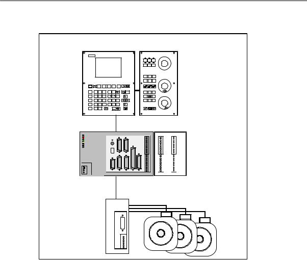
It consists of the following hardware components:
SENC: Control component for a maximum of 3 analog axes and an analog interface for a main spindle drive (ENC = Economical Numerical Control)
SOP020: NC operator panel with graphics display and keyboard
SMCP: machine control panel
SDI/O16: 16 binary inputs/outputs each extendable to max. 64 by using 4 modules
|
SINUMERIK 802C |
1-9 |
|
6FC5 597–3AA20–0BP2 (01.02) |
SINUMERIK 802C Control System
1.1Components of the SINUMERIK 802C
OP020 MCP
|
INC JOG |
REF |
|||||||||||
|
AUTO SBL |
MDA |
|||||||||||
|
M |
||||||||||||
|
N |
X |
Y |
Z |
T |
D |
VM |
+X |
% |
||||
|
G E |
7 > |
8 |
9 + |
K |
Pg |
-Z |
+Z |
|||||
|
F O |
4 < |
5 |
6 |
LA _ |
P |
R |
-X |
|||||
|
S Q |
1 |
2 |
3 = |
AF U B V C W |
Pg |
|||||||
|
M H |
0 |
$ |
INS |
% |
||||||||
|
ENCODER1ENCODER2 |
X10 |
X2003 |
X2005 |
|||||||||
|
X3 |
X4 |
MPG |
IN |
OUT |
||||||||
|
ERR |
L+ |
|||||||||||
|
0 |
0 |
|||||||||||
|
POK |
S2 |
1 |
1 |
|||||||||
|
DIAG |
S3 |
2 |
2 |
|||||||||
|
3 |
3 |
|||||||||||
|
4 |
4 |
|||||||||||
|
5 |
5 |
|||||||||||
|
D15 |
6 |
6 |
||||||||||
|
7 |
7 |
|||||||||||
|
M |
M |
|||||||||||
|
L+ |
||||||||||||
|
8 |
8 |
|||||||||||
|
9 |
9 |
|||||||||||
|
10 |
10 |
|||||||||||
|
DC24V X1 |
11 |
11 |
||||||||||
|
12 |
12 |
|||||||||||
|
13 |
13 |
|||||||||||
|
PE |
14 |
14 |
||||||||||
|
15 |
15 |
|||||||||||
|
M |
M |
M |
||||||||||
|
L+ |
||||||||||||
|
M |
RS232ENCODER3SPINDLEAXIS |
OPI |
DI |
X2004 |
X2006 |
|||||||
|
X2 |
X5 |
X6 |
X7 |
X8 |
X20 |
|||||||
|
ENC |
DI/O |
External analog drive
Fig. 1-1 SINUMERIK 802C hardware components (example configuration)
Software components
The SINUMERIK 802C comprises the following software components, which can be ordered:
SSystem software on the permanent flash memory of the ENC
–Boot software,
loads the remaining system software from the permanent memory into the user memory (DRAM) and starts the system.
–MMC software (Man Machine Communication), implements all operating functions
–NCK software (NC Kernel)
implements all NC functions. This software controls an NC channel with a maximum of 3 movement axes and a spindle.
–PLC software (Programmable Logic Control), executes the integrated PLC user program cyclically.
–Integrated PLC user program
intended to adjust the SINUMERIK 802C to the machine functions (see also Description of Functions “Integrated User Program for SINUMERIK 802C”).
|
1-10 |
SINUMERIK 802C |
|
6FC5 597–3AA20–0BP2 (01.02) |
![]()
SINUMERIK 802C Control System
1.1 Components of the SINUMERIK 802C
SToolbox
–WinPCIN transfer program for a PC/PG (programming device) to transfer user data and programs
–Text manager
–Cycle kit for loading into the control system using WinPCIN
–User program library
–Technological machine data files
–Programming tool
SUpdate diskettes
–Update program with operator prompting system
–802C system software, packed, for loading and programming the SINUMERIK 802C via an update program.
User data
User data are:
SMachine data
SSetting data
STool data
SR parameters
SZero offsets
SCompensation data
SPart programs
SStandard cycles
Data saving
Modified user data are saved for at least 50 h after power off or power failure. After then, they might get lost.
Warning
!To avoid data loss, the operator must carry out data saving (see Section 4.1.4).
|
SINUMERIK 802C |
1-11 |
|
6FC5 597–3AA20–0BP2 (01.02) |

SINUMERIK 802C Control System
1.2Technical data
1.2Technical data
Connected load
|
Table 1-1 |
Connected load |
|||||||
|
Parameter |
Min. |
Typ. |
Max. |
Unit |
||||
|
Supply voltage |
20.4 |
28.8 |
V |
|||||
|
Ripple |
3.6 |
Vss |
||||||
|
Current consumption from 24 V |
1 |
A |
* |
|||||
|
Power dissipation of ENC |
15 |
W |
||||||
|
Power dissipation of OP020 |
7 |
W |
||||||
|
Power dissipation of MCP |
— |
|||||||
|
Power dissipation of DI/O16 |
7 |
W |
** |
|||||
|
Start–up current |
2.6 |
A |
||||||
|
* |
Basic configuration of ENC, |
further DI/O16 |
connected |
|||||
|
OP020, MCP and DI/O16, all |
will increase by 0.05 A each. |
|||||||
|
outputs open, |
** |
at nominal load |
||||||
|
current consumption for any |
Weight
|
Table 1-2 |
Weight |
|
|
Component |
Weight [g] |
|
|
ENC component |
900 g |
|
|
DI/O16 component |
350 g |
|
|
OP020 component |
1,800 g |
|
|
MCP component |
1,200 g |
|
Dimensions
|
Table 1-3 |
Component dimensions |
|
|
Component |
Dimensions HxWxD [mm] |
|
|
ENC component |
125 x 200 x 118 |
|
|
DI/O component |
125 x 80 x 118 |
|
|
OP020 component |
300 x 250 x 50 |
|
|
MCP component |
300 x 170 x 50 |
|
|
1-12 |
SINUMERIK 802C |
|
6FC5 597–3AA20–0BP2 (01.02) |

SINUMERIK 802C Control System
1.2 Technical data
Environmental operating conditions
|
Table 1-4 |
Environmental operating conditions |
|
|
Parameter |
||
|
Temperature range |
0…55 °C |
|
|
Permissible relative humidity |
5…95 % without condensation |
|
|
Air pressure |
700…1,060 hPa |
|
The operating conditions comply with IEC 1131-2.
Installation in a housing (e.g. cubicle) is absolutely necessary for operation.
Transport and storage conditions
|
Table 1-5 |
Transport and storage conditions |
|
|
Parameter |
||
|
Temperature range |
Transport: -40…70 °C |
|
|
Storage: –20 … 55 °C |
||
|
Permissible relative air humidity |
5…95 % without condensation |
|
|
Air pressure |
700…1,060 hPa |
|
|
Transport height |
-1,000…3,000 m |
|
|
Free fall in transport package |
v 1,200 mm |
|
Protective quality and degree of protection
Class of protection I to IEC 536.
No PE terminal required.
Foreign matter and water protection to IEC 529.
Sfor ENC and DI/O16: IP 20
Sfor OP020 and MCP: IP 54 front
IP 00 rear
|
SINUMERIK 802C |
1-13 |
|
6FC5 597–3AA20–0BP2 (01.02) |
SINUMERIK 802C Control System
1.2Technical data
|
1-14 |
SINUMERIK 802C |
|
6FC5 597–3AA20–0BP2 (01.02) |

|
Installing the Control System |
2 |
2.1Installing and removing the SINUMERIK 802C
Warning
!Before performing any installation work, always first make sure that the system is disconnected from the mains!
The modules contain electrostatically sensitive devices.
It must be ensured that persons without ESD protection never touch printed circuit boards or components when handling operator and machine control panels.
Approach
Prior to installation, the machine control panel can be provided with a spindle override switch and an emergency stop button. If these are not required, the openings must be covered with the supplied self–adhesive covers.
1.Mount the spindle override switch.
2.Install the operator panel and the machine control panel.
3.Connect the panel using ribbon cable.
4.Install the DIN rail.
5.Connect the ENC and DI/O components.
Note
If you want to connect several DI/O16 components, it may be necessary to remove the right– hand connector from the housing.
6. Slide the components onto the DIN rail, tilt it down and screw it tight.
Removing the control system
The control components are removed as described above in the reverse order.
|
SINUMERIK 802C |
2-15 |
|
6FC5 597–3AA20–0BP2 (01.02) |

Installing the Control System
2.1 Installing and removing the SINUMERIK 802C
Warning
!Before removing the control components, always first make sure that the system is disconnected from the mains!
|
2-16 |
SINUMERIK 802C |
|
6FC5 597–3AA20–0BP2 (01.02) |

Installing the Control System
2.1Installing and removing the SINUMERIK 802C
Mounting dimensions
The dimensions shown below are important for installing the control components:
|
8 |
250 |
170 |
||||||||
|
142 |
||||||||||
|
300 |
||||||||||
|
SubD |
||||||||||
|
142 |
A |
|||||||||
|
F |
||||||||||
|
8 |
234 |
154 |
45 |
|||||||
|
8 |
||||||||||
|
80 |
||||||||||
|
Mounting |
4,8 |
|||||||||
|
482 |
40 |
|||||||||
|
120 |
||||||||||
|
32,5 |
ENCODER1 |
ENCODER2 |
X10 |
X2003 |
X2005 |
|||||
|
IN |
OUT |
|||||||||
|
X3 |
X4 |
MPG |
L+ |
|||||||
|
ERR |
||||||||||
|
0 |
0 |
|||||||||
|
POK |
1 |
1 |
||||||||
|
DIAG |
2 |
2 |
||||||||
|
3 |
3 |
|||||||||
|
4 |
4 |
|||||||||
|
5 |
5 |
|||||||||
|
6 |
6 |
|||||||||
|
57,2 |
7 |
7 |
125 |
|||||||
|
9 |
9 |
|||||||||
|
M |
M |
|||||||||
|
L+ |
||||||||||
|
8 |
8 |
|||||||||
|
10 |
10 |
|||||||||
|
DC24V X1 |
11 |
11 |
||||||||
|
12 |
12 |
|||||||||
|
13 |
13 |
|||||||||
|
20 |
L+ |
14 |
14 |
|||||||
|
M |
15 |
15 |
||||||||
|
L+ |
M |
M |
||||||||
|
M |
RS232 |
ENCODER3 |
SPINDLE |
AXIS |
OPI |
DI |
||||
|
X2 |
X5 |
X6 |
X7 |
X8 |
X20 |
X2004 |
X2006 |
|||
|
200 |
80 |
|||||||||
|
15 |
||||||||||
|
40 |
Fig. 2-1 Mounting dimensions for SINUMERIK 802C
|
SINUMERIK 802C |
2-17 |
|
6FC5 597–3AA20–0BP2 (01.02) |

Installing the Control System
2.2Interfaces and cables
2.2Interfaces and cables
Position of the interfaces and front panel elements
|
ECU |
DI/O16 |
|||||||
|
ENCODER1 ENCODER2 |
X10 |
X2003 |
X2005 |
|||||
|
X3 |
X4 |
MPG |
IN |
OUT |
||||
|
ERR |
L+ |
|||||||
|
0 |
0 |
|||||||
|
POK |
S2 |
1 |
1 |
|||||
|
DIAG |
S3 |
2 |
2 |
|||||
|
3 |
3 |
|||||||
|
4 |
4 |
|||||||
|
5 |
5 |
|||||||
|
D15 |
6 |
6 |
||||||
|
7 |
7 |
|||||||
|
M |
M |
|||||||
|
L+ |
||||||||
|
8 |
8 |
|||||||
|
9 |
9 |
|||||||
|
10 |
10 |
|||||||
|
DC24V X1 |
11 |
11 |
||||||
|
12 |
12 |
|||||||
|
13 |
13 |
|||||||
|
PE |
14 |
14 |
||||||
|
15 |
15 |
|||||||
|
M |
||||||||
|
M |
M |
|||||||
|
L+ |
||||||||
|
M |
RS232 |
ENCODER3 |
SPINDLE |
AXIS |
OPI |
DI |
X2004 |
X2006 |
|
X2 |
X5 |
X6 |
X7 |
X8 |
X20 |
Fig. 2-2 User interfaces
|
MCP |
OP020 |
|
|
Rear |
Rear |
|
|
X1202 |
CFL |
|
|
X1201 |
||
|
LCDsignal |
||
|
X1001 X1002 X1009 |
connector |
Fig. 2-3 Rear of machine control panel and operator panel
|
2-18 |
SINUMERIK 802C |
|
6FC5 597–3AA20–0BP2 (01.02) |

Installing the Control System
2.2 Interfaces and cables
Interfaces
ENC
SX1 power supply terminals (DC24V)
4–pin screw–type terminal block for connecting the 24 V load power supply
SX2 RS232 interface (V24)
9–pin sub–D plug connector
SX3 to X5 measuring system interfaces (ENCODER)
three 15–pin sub–D plug connectors for connecting incremental position encoders (RS422)
SX6 spindle interface (SPINDLE)
9–pin sub–D socket for connecting a spindle drive with analog interface
SX7 drive interface (AXIS)
50–pin sub–D socket connector for connecting the power sections for a maximum of four analog drives including spindle
SX8 operator terminal interface (OPI)
25–pin D–Sub female connector for connecting the operator terminal
SX10 handwheel interface (MPG)
10–pin front connector for connecting the handwheels
SX20 digital inputs (DI)
10–pin front connector for connecting the NC READY relay
DI/O
SX2003 and X2004
10–pin front connector for connecting digital inputs
SX2005 and X2006
10–pin front connector for connecting digital outputs
LEDs
3 LEDs for fault and status displays
Operating elements
Start–up switch S
|
SINUMERIK 802C |
2-19 |
|
6FC5 597–3AA20–0BP2 (01.02) |

Installing the Control System
2.2Interfaces and cables
Connecting cables
The components are wired up as shown in the Connection Diagram 2-4. For the cables required, please refer to the diagram below.
|
DC24V |
X1 |
L+ |
||||||||
|
M |
Wire (1.0…2.5) |
|||||||||
|
ECU |
||||||||||
|
Machine |
||||||||||
|
RS232 |
Control |
|||||||||
|
X2 |
Panel |
|||||||||
|
RS232 |
Op. Panel |
|||||||||
|
1) |
||||||||||
|
OPI |
flat or round |
|||||||||
|
X8 |
X1009 |
X1002X1001 |
cable |
1) |
X1202X1201 |
|||||
|
AXIS |
X7 |
ANALOG DRIVE |
||||||||
|
ANALOG MOTOR |
||||||||||
|
SPINDLE |
||||||||||
|
DRIVE |
||||||||||
|
SPINDLE |
X6 |
|||||||||
|
ENCODER |
SPINDLE MOTOR |
|||||||||
|
–X5 |
ENCODER |
|||||||||
|
ENCODER |
||||||||||
|
X3 |
||||||||||
|
MPG |
X10 |
Hand Wheels |
||||||||
|
DI |
X20 |
NC READY |
||||||||
|
DI/O16 |
X2003 |
X2004 |
IN |
Sensor |
||||||
|
1…16 |
||||||||||
|
IN 0..7 |
Wire (0.14…1.5) |
|||||||||
|
M |
||||||||||
|
IN 8..15 |
||||||||||
|
X2006 |
L+ |
|||||||||
|
OUT0..7 |
X2005 |
OUT |
Wire (0.14…1.5) |
Actor |
||||||
|
OUT8..15 |
||||||||||
|
M |
1…16 |
|||||||||
|
M |
P24 |
M P24 |
||||||||
|
Power Supply |
Fig. 2-4 SINUMERIK 802C connection diagram
1) Ribbon cable (included in scope of supply)
|
2-20 |
SINUMERIK 802C |
|
6FC5 597–3AA20–0BP2 (01.02) |
![]()
Installing the Control System
2.3 Connecting the individual components
2.3Connecting the individual components
Connecting the components
Note
Use only shielded cable and make sure that the shield is connected to the metal or metal plated connector casing on the control side. For the purpose of isolating the analog setpoint signal from low–frequency interference, we recommend not to ground the shield on the drive side.
The preassembled cable offered as accessories provides optimum protection against interference.
General procedure:
Proceed as follows to connect the individual components:
1.Connect the cables to the components as shown in Fig. 2-4.
2.Fix the sub–D connector in place using the knurled screws.
2.3.1Connecting the operator panel
Connector pin assignment on the ENC side
|
Operator panel interface |
|
|
Connector designation: |
X8 |
|
OP020 |
|
|
Connector type: |
25–pin sub–D plug connector |
|
SINUMERIK 802C |
2-21 |
|
6FC5 597–3AA20–0BP2 (01.02) |
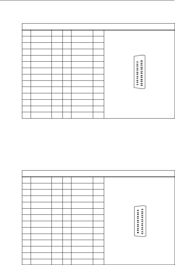
Installing the Control System
2.3Connecting the individual components
|
Table 2-1 |
Pin assignment of connector X8 |
|||||||
|
X8 |
||||||||
|
Pin |
Signal |
Type |
Pin |
Signal |
Type |
|||
|
1 |
14 |
P24_OP |
VO |
|||||
|
2 |
M_OP |
VO |
15 |
OPD0_N |
O |
|||
|
3 |
OPD0 |
O |
16 |
OPD1_N |
O |
|||
|
4 |
OPD1 |
O |
17 |
OPD2_N |
O |
25 |
13 |
|
|
5 |
OPD2 |
O |
18 |
OPD3_N |
O |
|||
|
6 |
OPD3 |
O |
19 |
OPCP1_N |
O |
|||
|
7 |
OPCP1 |
O |
20 |
OPCP2_N |
O |
|||
|
8 |
OPCP2 |
O |
21 |
OPS_N |
O |
14 |
1 |
|
|
9 |
OPS |
O |
22 |
ENRXD_N |
I |
|||
|
10 |
ENRXD |
I |
23 |
ENTXD_N |
O |
|||
|
11 |
ENTXD |
O |
24 |
ENRTS_N |
O |
|||
|
12 |
ENRTS |
O |
25 |
P24_OP |
VO |
|||
|
13 |
M_OP |
VO |
Connector pin assignment on the OP side
|
Operator panel interface |
||||||||
|
Connector designation: |
X1009 |
|||||||
|
OP020 |
||||||||
|
Connector type: |
25–pin sub–D plug connector |
|||||||
|
Table 2-2 |
Pin assignment of connector X1009 |
|||||||
|
X1009 |
||||||||
|
Pin |
Signal |
Type |
Pin |
Signal |
Type |
|||
|
1 |
14 |
P24_OP |
VI |
|||||
|
2 |
M_OP |
VI |
15 |
OPD0_N |
I |
|||
|
3 |
OPD0 |
I |
16 |
OPD1_N |
I |
|||
|
4 |
OPD1 |
I |
17 |
OPD2_N |
I |
|||
|
5 |
OPD2 |
I |
18 |
OPD3_N |
I |
25 |
13 |
|
|
6 |
OPD3 |
I |
19 |
OPCP1_N |
I |
|||
|
7 |
OPCP1 |
I |
20 |
OPCP2_N |
I |
|||
|
8 |
OPCP2 |
I |
21 |
OPS_N |
I |
14 |
||
|
9 |
OPS |
I |
22 |
OPTXD_N |
O |
1 |
||
|
10 |
OPTXD |
O |
23 |
OPRXD_N |
I |
|||
|
11 |
OPRXD |
I |
24 |
OPCTS_N |
I |
|||
|
12 |
OPCTS |
I |
25 |
P24_OP |
VI |
|||
|
13 |
M_OP |
VI |
|
2-22 |
SINUMERIK 802C |
|
6FC5 597–3AA20–0BP2 (01.02) |
|
Installing the Control System |
||
|
2.3 |
Connecting the individual components |
|
|
Signal names |
||
|
OPD[0…3] |
LCD Data 0…3 |
|
|
OPCP1 |
LCD Latch |
|
|
OPS |
LCD Frame |
|
|
OPCP2 |
LCD Clock |
|
|
OPRXD |
OP Receive Data |
|
|
OPTXD |
OP Transmit Data |
|
|
OPCTS |
OP Clear to Send |
|
|
ENRXD |
ECU Receive Data |
|
|
ENTXD |
ECU Transmit Data |
|
|
ENRTS |
ECU Request to Send |
|
|
P24_OP |
DC24V |
|
|
M_OP |
Ground |
|
|
Signal level |
||
|
RS422 / LVDS |
||
|
Signal type |
||
|
VO |
Voltage output |
|
|
VI |
Voltage input |
|
|
O |
Output |
|
|
I |
Input |
2.3.2Connecting the feed drives and the spindle (X7)
Connector pin assignment on the ENC side
Feed drive interface
|
Connector designation: |
X7 |
|||||||||
|
AXIS 1-4 |
||||||||||
|
Connector type: |
50–pin sub–D plug connector |
|||||||||
|
Table 2-3 |
Pin assignment of connector X7 |
|||||||||
|
X7 |
||||||||||
|
Pin |
Signal |
Type |
Pin |
Signal |
Type |
Pin |
Signal |
Type |
||
|
1 |
SW1 |
VO |
18 |
34 |
BS1 |
VO |
||||
|
2 |
BS2 |
VO |
19 |
35 |
SW2 |
VO |
||||
|
3 |
SW3 |
VO |
20 |
36 |
BS3 |
VO |
||||
|
4 |
BS4 |
VO |
21 |
37 |
SW4 |
VO |
||||
|
5 |
22 |
38 |
||||||||
|
6 |
23 |
39 |
||||||||
|
7 |
24 |
40 |
||||||||
|
8 |
25 |
41 |
||||||||
|
9 |
26 |
42 |
||||||||
|
10 |
27 |
43 |
||||||||
|
SINUMERIK 802C |
2-23 |
|
6FC5 597–3AA20–0BP2 (01.02) |

Installing the Control System
2.3Connecting the individual components
|
11 |
28 |
44 |
||||||||
|
12 |
29 |
45 |
||||||||
|
13 |
30 |
46 |
||||||||
|
14 |
RF1.1 |
K |
31 |
47 |
RF1.2 |
K |
||||
|
15 |
RF2.1 |
K |
32 |
48 |
RF2.2 |
K |
||||
|
16 |
RF3.1 |
K |
33 |
49 |
RF3.2 |
K |
||||
|
17 |
RF4.1 |
K |
50 |
RF4.2 |
K |
|||||
|
Signal names |
||||||||||
|
SWn |
Setpoint |
|||||||||
|
BSn |
Reference potential for setpoint |
|||||||||
|
RFn.1, RFn.2 |
Servo enable contact |
|||||||||
|
Signal level |
||||||||||
|
RS422 |
||||||||||
|
Signal type |
||||||||||
|
O |
Signal output |
Axis assignment
1X axis
2Y axis
3Z axis
4Spindle
|
2-24 |
SINUMERIK 802C |
|
6FC5 597–3AA20–0BP2 (01.02) |
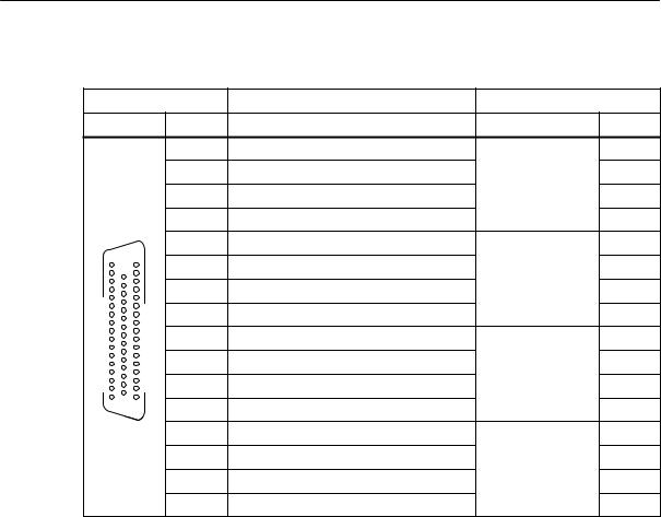
Installing the Control System
2.3 Connecting the individual components
Table 2-4 Cable assignment (for type 6FX2 002–3AD01)
|
NC Side |
Cable |
Drive Side |
||||
|
PIN |
Core Color |
Signal Name |
PIN |
|||
|
14 |
black |
1st axis |
1.9 |
|||
|
47 |
brown |
1.65 |
||||
|
34 |
red |
1.4 |
||||
|
1 |
orange |
1.56 |
||||
|
15 |
yellow |
2nd axis |
2.9 |
|||
|
34 |
18 |
1 |
48 |
green |
2.65 |
|
|
2 |
blue |
2.14 |
||||
|
35 |
purple |
2.56 |
||||
|
16 |
gray |
3rd axis |
3.9 |
|||
|
49 |
pink |
3.65 |
||||
|
36 |
white/black |
3.14 |
||||
|
50 |
33 |
17 |
3 |
white/brown |
3.56 |
|
|
17 |
white/red |
Spindle |
4.9 |
|||
|
50 |
white/orange |
4.65 |
||||
|
4 |
white/yellow |
4.14 |
||||
|
37 |
white/green |
4.56 |
Drives with analog interface Signals
One voltage and one enable signal each is output.
SSWn (SETPOINT)
Analog voltage signal in the range «10 V to output a speed setpoint
SSn (REFERENCE SIGNAL)
Reference potential (analog ground) for the setpoint signal, internally connected to logic ground.
SRFn (SERVO ENABLE)
Relay contact pair controlling the enable of the power section, e.g. of a SIMODRIVE drive unit controlled via a PLC program.
Signal parameters
The setpoint is output as an analog differential signal.
|
Table 2-5 |
Electrical parameters of the signal outputs for step–switching drives |
||||
|
Parameter |
Min |
Max |
Unit |
||
|
Voltage range |
-10.5 |
10.5 |
V |
||
|
Output current |
-3 |
3 |
mA |
||
|
SINUMERIK 802C |
2-25 |
|
6FC5 597–3AA20–0BP2 (01.02) |
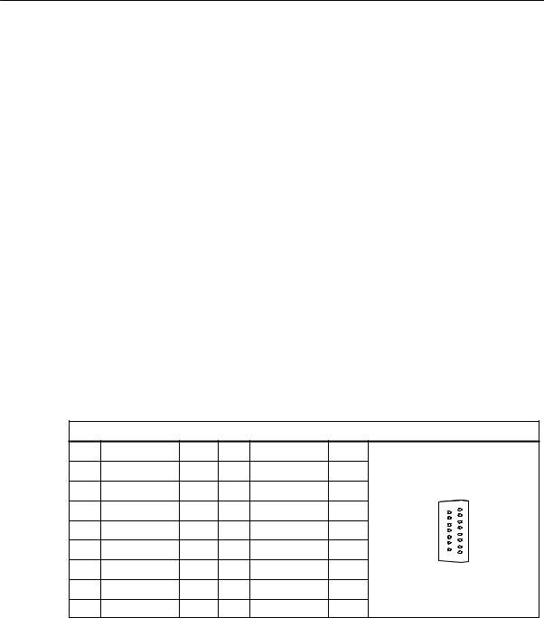
Installing the Control System
2.3Connecting the individual components
Relay contact
|
Table 2-6 |
Electrical parameters of the relay contacts RFn.1 and RFn.2 |
|||
|
Parameter |
Max. |
Unit |
||
|
Switching voltage |
50 |
V |
||
|
Switching current |
1 |
A |
||
|
Switching power |
30 |
VA |
||
Cable length: max. 35 m
2.3.3Connecting the measuring systems (X3 … X6)
Pin assignment of the connector on the ENC side
Measuring system interface (incremental encoder)
|
Connector designation: |
X3 … X6 |
||||||||
|
ENCODER |
|||||||||
|
Connector type: |
15–pin sub–D plug connector |
||||||||
|
Table 2-7 |
Pin assignment of the female connector X3 … X6 |
||||||||
|
X3 … X6 |
|||||||||
|
Pin |
Signal |
Type |
Pin |
Signal |
Type |
||||
|
1 |
9 |
M |
VO |
||||||
|
2 |
10 |
N |
I |
||||||
|
3 |
11 |
N_N |
I |
15 |
8 |
||||
|
4 |
P5_MS |
VO |
12 |
B_N |
I |
||||
|
5 |
VO |
13 |
B |
I |
9 |
1 |
|||
|
6 |
P5_MS |
VO |
14 |
A_N |
I |
||||
|
7 |
M |
VO |
15 |
A |
I |
||||
|
8 |
|||||||||
|
Signal names |
|||||||||
|
A, A_N |
Track A (true and negated) |
||||||||
|
B, B_N |
Track B (true and negated) |
||||||||
|
N, N_N |
Zero mark (true and negated) |
||||||||
|
P5_MS |
+5.2 V supply |
||||||||
|
M |
Supply ground |
||||||||
|
Signal level |
|||||||||
|
RS422 |
|||||||||
|
Signal type |
|||||||||
|
VO |
Voltage output (supply) |
||||||||
|
I |
5V input (5V signal) |
|
2-26 |
SINUMERIK 802C |
|
6FC5 597–3AA20–0BP2 (01.02) |

Installing the Control System
2.3 Connecting the individual components
Connectable encoder types
Incremental 5 V encoders can be connected directly.
Characteristics
The encoders must meet the following requirements:
|
Transmission method: |
Differential transmission with 5 V square–wave |
||||
|
signalsOutput signals: |
|||||
|
Track A as true and negated signal (Ua1, |
) |
||||
|
Ua1 |
|||||
|
Track B as true and negated signal (Ua2, |
) |
||||
|
Ua2 |
|||||
|
Zero signal N as true and negated signal |
|||||
|
(Ua0, |
) |
||||
|
Ua0 |
|||||
|
Max. output frequency: |
1.5 MHz |
||||
|
Phase offset between |
|||||
|
tracks A and B: |
90° «30° |
||||
|
Current consumption: |
max. 300 mA |
Cable lengths
The maximum cable length depends on the specifications of the encoder power supply and on the transmission frequency.
To provide fault–free operation, make sure that the following values are not exceeded when using preassembled interconnecting cables from SIEMENS:
|
Table 2-8 |
Maximum cable lengths depending on the encoder power supply |
||||||
|
Supply Voltage |
Tolerance |
Current Consumption |
Max. Cable Length |
||||
|
5 V DC |
4.75 V…5.25 V |
< 300 mA |
25 m |
||||
|
5 V DC |
4.75 V…5.25 V |
< 220 mA |
35 m |
||||
|
Table 2-9 |
Maximum cable lengths depending on the transmission frequency |
||||||
|
Encoder Type |
Frequency |
Max. Cable Length |
|||||
|
incremental |
1 MHz |
10 m |
|||||
|
500 kHz |
35 m |
||||||
2.3.4Configuration of the RS232 interface connection (X8)
Pin assignment of the connector on the ENC side
|
RS232 interface |
|
|
Connector designation: |
X2 |
|
RS232 |
|
|
Connector type: |
9–pin sub–D plug connector |
|
SINUMERIK 802C |
2-27 |
|
6FC5 597–3AA20–0BP2 (01.02) |
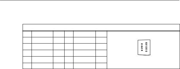
Installing the Control System
2.3Connecting the individual components
Table 2-10 Pin assignment of connector X2
|
X8 |
||||||||
|
Pin |
Name |
Type |
Pin |
Name |
Type |
|||
|
1 |
6 |
DSR |
I |
1 |
||||
|
2 |
RxD |
I |
7 |
RTS |
O |
6 |
||
|
3 |
TxD |
O |
8 |
CTS |
I |
9 |
5 |
|
|
4 |
DTR |
O |
9 |
|||||
|
5 |
M |
VO |
||||||
|
Signal description: |
||||||||
|
RxD |
Receive data |
|||||||
|
TxD |
Send data |
|||||||
|
RTS |
Request to send |
|||||||
|
CTS |
Send enable |
|||||||
|
DTR |
Standby output |
|||||||
|
DSR |
Standby input |
|||||||
|
M |
Ground |
|||||||
|
Signal level |
||||||||
|
RS232 (+ 12 V) |
||||||||
|
Signal type |
||||||||
|
I |
Input |
|||||||
|
O |
Output |
|||||||
|
VO |
Voltage output |
Cable for WinPCIN
Table 2-11 Cable for WinPCIN: Pin assignment of the Sub–D connector
|
9–Pin |
Name |
25–Pin |
|
1 |
Shield |
1 |
|
2 |
RxD |
2 |
|
3 |
TxD |
3 |
|
4 |
DTR |
6 |
|
5 |
M |
7 |
|
6 |
DSR |
20 |
|
7 |
RTS |
5 |
|
8 |
CTS |
4 |
|
9 |
||
|
2-28 |
SINUMERIK 802C |
|
6FC5 597–3AA20–0BP2 (01.02) |
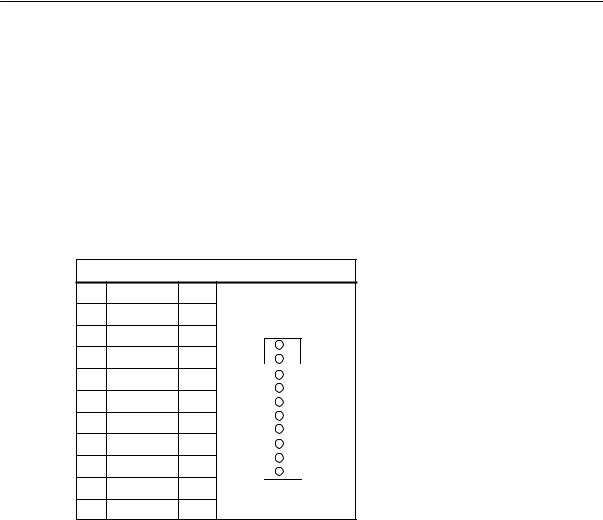
Installing the Control System
2.3 Connecting the individual components
2.3.5Connecting handwheels (X10)
Pin assignment of the connector on the ENC side
Handwheel interface
|
Connector designation: |
X10 |
|||
|
MPG |
||||
|
Connector type: |
10–pin mini-Combicon plug connector |
|||
|
Table 2-12 Pin assignment of connector |
||||
|
X10 |
||||
|
X10 |
||||
|
Pin |
Name |
Type |
||
|
1 |
A1 |
I |
||
|
2 |
A1_N |
I |
1 |
|
|
3 |
B1 |
I |
||
|
4 |
B1_N |
I |
||
|
5 |
P5_MS |
VO |
||
|
6 |
M5_MS |
VO |
||
|
7 |
A2 |
I |
||
|
8 |
A2_N |
I |
10 |
|
|
9 |
B2 |
I |
||
|
10 |
B2_N |
I |
Signal names
A1, A1_N
B1, B1_N
A2, A2_N
B2, B2_N
P5_MS
M
Signal level
RS422
Signal type
VO
I
Handwheels
Track A, true and negated (handwheel 1) Track B, true and negated (handwheel 1) Track A, true and negated (handwheel 2) Track B, true and negated (handwheel 2) 5.2 V supply voltage for handwheels Supply ground
Voltage output
Input (5 V signal)
Two electronic handwheels can be connected which must meet the following requirements:
|
Transmission method: |
5 V square–wave (TTL level or RS422) |
||
|
Signals: |
Track A as true and negated signal (Ua1, |
) |
|
|
Ua1 |
|||
|
Track B as true and negated signal (Ua2, |
Ua2 |
) |
|
SINUMERIK 802C |
2-29 |
|
6FC5 597–3AA20–0BP2 (01.02) |

Installing the Control System
2.3Connecting the individual components
|
Max. output frequency: |
500 kHz |
|
Phase offset between |
|
|
tracks A and B: |
90° «30° |
|
Supply: |
5 V, max. 250 mA |
2.3.6Connecting NCREADY (X20)
Pin assignment of the connector on the ENC side
BERO input interface
|
Connector designation: |
X20 |
||
|
DI |
|||
|
Connector type: |
10–pin plug connector |
||
|
Table 2-13Pin assignment of connector X20 |
|||
|
X20 |
|||
|
Pin |
Name |
Type |
|
|
11 |
NCRDY_1 |
K |
|
|
12 |
NCRDY_2 |
K |
11 |
|
13 |
reserved |
DI |
|
|
14 |
reserved |
DI |
|
|
15 |
reserved |
DI |
|
|
16 |
reserved |
DI |
|
|
17 |
reserved |
DI |
|
|
18 |
reserved |
DI |
20 |
|
19 |
reserved |
VI |
|
|
20 |
reserved |
VI |
|
|
Signal names |
|||
|
NCRDY_1…2 |
NC Ready (NCREADY contacts 1…2) |
||
|
Signal type |
|||
|
K |
Switching contact |
NC-READY output
Readiness in the form of a relay contact (NO); must be integrated into the EMERGENCY STOP circuit.
|
2-30 |
SINUMERIK 802C |
|
6FC5 597–3AA20–0BP2 (01.02) |
![]()
Installing the Control System
|
2.3 |
Connecting the individual components |
||
|
Table 2-14 Electrical parameters of the NCREADY relay contact |
|||
|
Parameter |
Max. |
Unit |
|
|
DC switching voltage |
50 |
V |
|
|
Switching current |
1 |
A |
|
|
Switching power |
30 |
VA |
|
L+
EMERGENCY STOP
X20.11
NCREADY
X20.12
Machine control voltage
Fig. 2-5
The NCREADY contact will switch off the control voltage in case of danger.
2.3.7Connecting the digital inputs and outputs (X2003 … X2006)
Connector pin assignment
Interface for the digital inputs
|
Connector |
designation: |
X2003, X2004 |
|
IN |
||
|
Connector |
type: |
10–pin plug connector |
|
SINUMERIK 802C |
2-31 |
|
6FC5 597–3AA20–0BP2 (01.02) |

Installing the Control System
2.3Connecting the individual components
Table 2-15 Connector pin assignment
|
X2003 |
|||||
|
Pin |
Name |
Type |
|||
|
1 |
|||||
|
2 |
DI0 |
I |
|||
|
3 |
DI1 |
I |
|||
|
4 |
DI2 |
I |
|||
|
5 |
DI3 |
I |
|||
|
6 |
DI4 |
I |
|||
|
7 |
DI5 |
I |
|||
|
8 |
DI6 |
I |
|||
|
9 |
DI7 |
I |
|||
|
10 |
M24 |
V |
|||
|
X2004 |
|||||
|
Pin |
Name |
Type |
|||
|
1 |
|||||
|
2 |
DI8 |
I |
|||
|
3 |
DI9 |
I |
|||
|
4 |
DI10 |
I |
|||
|
5 |
DI11 |
I |
|||
|
6 |
DI12 |
I |
|||
|
7 |
DI13 |
I |
|||
|
8 |
DI14 |
I |
|||
|
9 |
DI15 |
I |
|||
|
10 |
M24 |
V |
|||
|
Signal names |
|
|
DI0…15 |
24 V digital inputs |
|
Signal type |
|
|
V |
Voltage input |
|
I |
Input (24 V signal) |
|
2-32 |
SINUMERIK 802C |
|
6FC5 597–3AA20–0BP2 (01.02) |

Installing the Control System
|
2.3 |
Connecting the individual components |
||||||
|
Table 2-16 Electrical parameters of the digital inputs |
|||||||
|
Parameter |
Value |
Unit |
Note |
||||
|
“1” signal, voltage range |
15…30 |
V |
|||||
|
“1” signal, current consumption |
2…15 |
mA |
|||||
|
“0” signal, voltage range |
-3…5 |
V |
or input open |
||||
|
Signal delay 0 ³ 1 |
0.5…3 |
ms |
|||||
|
Signal delay 1 ³ 0 |
0.5…3 |
ms |
|||||
|
Connector pin assignment |
|||||||
|
Interface for digital outputs |
|||||||
|
Connector |
designation: |
X2005, X2006 |
|||||
|
OUT |
|||||||
|
Connector |
type: |
10–pin plug connector |
|||||
|
Table 2-17 Connector pin assignment |
|||||||
|
X2005 |
|||||||
|
Pin |
Name |
Type |
|||||
|
1 |
1P24 |
V |
|||||
|
2 |
DO0 |
O |
|||||
|
3 |
DO1 |
O |
|||||
|
4 |
DO2 |
O |
|||||
|
5 |
DO3 |
O |
|||||
|
6 |
DO4 |
O |
|||||
|
7 |
DO5 |
O |
|||||
|
8 |
DO6 |
O |
|||||
|
9 |
DO7 |
O |
|||||
|
10 |
1M24 |
V |
|||||
|
X2006 |
|||||||
|
Pin |
Name |
Type |
|||||
|
1 |
2P24 |
V |
|||||
|
2 |
DO8 |
O |
|||||
|
3 |
DO9 |
O |
|||||
|
4 |
DO10 |
O |
|||||
|
5 |
DO11 |
O |
|||||
|
6 |
DO12 |
O |
|||||
|
7 |
DO13 |
O |
|||||
|
8 |
DO14 |
O |
|||||
|
9 |
DO15 |
O |
|||||
|
10 |
2M24 |
V |
|
SINUMERIK 802C |
2-33 |
|
6FC5 597–3AA20–0BP2 (01.02) |

Installing the Control System
2.3Connecting the individual components
|
Signal names |
|||||
|
DO0…15 |
Digital outputs 24V/0.5A |
||||
|
Signal type |
|||||
|
V |
Voltage input |
||||
|
O |
Output (24 V signal) |
||||
|
Table 2-18 Electrical parameters of the digital outputs |
|||||
|
Parameter |
Value |
Unit |
Note |
||
|
“1” signal, nominal voltage |
24 |
V |
|||
|
Voltage drop |
max. 3 |
V |
|||
|
“1” signal, output current |
0.5 |
A |
Simultaneity factor |
||
|
0.5 per 16 outputs |
|||||
|
“0” signal, leakage current |
max. 2 |
mA |
|||
Connecting sensors and actuators
|
X2003 |
X2005 |
OUT |
|
IN |
||
|
L+ |
||
|
0 |
||
|
0 |
||
|
1 |
||
|
1 |
||
|
2 |
||
|
2 |
||
|
3 |
||
|
3 |
||
|
4 |
||
|
4 |
||
|
5 |
||
|
5 |
||
|
6 |
||
|
6 |
||
|
7 |
||
|
7 |
||
|
M |
||
|
M |
||
|
8 |
L+ |
|
|
8 |
||
|
9 |
||
|
9 |
||
|
10 |
10 |
|
|
11 |
||
|
11 |
||
|
12 |
12 |
|
|
13 |
13 |
|
|
14 |
14 |
|
|
15 |
15 |
|
|
M |
M |
|
|
X2004 |
X2006 |
Fig. 2-6 Connecting the digital inputs and outputs
|
2-34 |
SINUMERIK 802C |
|
6FC5 597–3AA20–0BP2 (01.02) |

Installing the Control System
2.4 ENC and operator panel power supply (X1)
2.4ENC and operator panel power supply (X1)
Screw–type terminal block
The 24 V DC load power supply unit required for supplying ENC and operator terminal is connected to screw–type terminal block X1.
Characteristics of the load power supply
The 24 V DC voltage must be generated as a functional extra–low voltage with safe electrical isolation (to IEC 204-1, Section 6.4, PELV).
Table 2-19 Electrical parameters of the load power supply
|
Parameter |
Min. |
Max. |
Units |
Conditions |
|
Voltage range mean value |
20.4 |
28.8 |
V |
|
|
Ripple |
3.6 |
Vss |
||
|
Non–periodic overvoltage |
35 |
V |
500 ms cont. |
|
|
50 s recovery |
||||
|
Rated current consumption |
1 |
A |
||
|
Starting current |
2.6 |
A |
||
Pin connector assignment on the ENC side
Table 2-20 Pin connector assignment of screw–type terminal
block X1
|
Terminal |
||
|
1 |
PE |
PE |
|
2 |
M |
Ground |
|
3 |
L+ |
DC 24 V |
|
4 |
M |
Ground |
The contacts 2/4 are connected internally in the device.
Operator panel
The operator panel does not possess a separate power supply connection. It is powered from the ENC via the signal cables.
|
SINUMERIK 802C |
2-35 |
|
6FC5 597–3AA20–0BP2 (01.02) |

Installing the Control System
2.5Grounding
2.5Grounding
Ground connections
The following ground connections must be implemented:
SBusbar for ENC, DI/O
SOP020 operator panel
SMachine control panel (MCP)
The ground connections for the MCP/OP020 must take into account installation in the machine or a panel.
In the case of cubicle installation, the grounding points must be connected to the grounding bar (see Fig. 2-7).
|
MCP |
OP020 |
|||||||
|
Installation in a cu- |
||||||||
|
CFL |
bicle or machine |
|||||||
|
LCD signal- |
||||||||
|
connector |
||||||||
|
Shielded signal |
||||||||
|
cable |
||||||||
|
ENC |
DI/O16 |
|||||||
|
ENCODER1 |
ENCODER2 |
X10 |
X2003 |
X2005 |
||||
|
X3 |
X4 |
MPG |
IN |
OUT |
||||
|
L+ |
||||||||
|
ERR |
||||||||
|
0 |
0 |
|||||||
|
POK |
1 |
1 |
||||||
|
DIAG |
2 |
2 |
||||||
|
3 |
3 |
|||||||
|
4 |
4 |
|||||||
|
5 |
5 |
|||||||
|
6 |
6 |
|||||||
|
7 |
7 |
|||||||
|
M |
M |
|||||||
|
L+ |
||||||||
|
8 |
8 |
|||||||
|
9 |
9 |
|||||||
|
10 |
10 |
|||||||
|
DC24V X1 |
11 |
11 |
||||||
|
12 |
12 |
|||||||
|
13 |
13 |
|||||||
|
L+ |
14 |
14 |
||||||
|
M |
15 |
15 |
||||||
|
L+ |
M |
M |
||||||
|
M |
RS232 |
ENCODER3 |
SPINDLE |
AXIS |
OPI |
DI |
||
|
X2 |
X5 |
X6 |
X7 |
X8 |
X20 |
X2004 |
X2006 |
|
|
to chassis |
||||||||
|
Grounding bar |
Fig. 2-7 Grounding diagram for MCP/OP020 installation in a cubicle or machine
|
2-36 |
SINUMERIK 802C |
|
6FC5 597–3AA20–0BP2 (01.02) |

Installing the Control System
2.5 Grounding
Panel installation requires that the ground connections on the MCP and OP020 are connected together and to the panel frame. The panel frame is grounded centrally (see Fig. 2-8 ).
|
MCP |
OP020 |
|||||||
|
Installation in a |
||||||||
|
CFL |
separate unit |
|||||||
|
LCD signal- |
||||||||
|
connector |
||||||||
|
Shielded signal |
||||||||
|
cable |
||||||||
|
ECU |
DI/O16 |
|||||||
|
ENCODER1 |
ENCODER2 |
X10 |
X2003 |
X2005 |
||||
|
X3 |
X4 |
MPG |
IN |
OUT |
||||
|
ERR |
L+ |
|||||||
|
0 |
0 |
|||||||
|
POK |
1 |
1 |
||||||
|
DIAG |
2 |
2 |
||||||
|
3 |
3 |
|||||||
|
4 |
4 |
|||||||
|
5 |
5 |
|||||||
|
6 |
6 |
|||||||
|
7 |
7 |
|||||||
|
M |
M |
|||||||
|
L+ |
||||||||
|
8 |
8 |
|||||||
|
9 |
9 |
|||||||
|
10 |
10 |
|||||||
|
DC24V X1 |
11 |
11 |
||||||
|
12 |
12 |
|||||||
|
13 |
13 |
|||||||
|
L+ |
14 |
14 |
||||||
|
M |
15 |
15 |
||||||
|
L+ |
M |
M |
||||||
|
M |
RS232 |
ENCODER3 |
SPINDLE |
AXIS |
OPI |
DI |
||
|
X2 |
X5 |
X6 |
X7 |
X8 |
X20 |
X2004 |
X2006 |
|
|
to chassis |
||||||||
|
Grounding bar |
Fig. 2-8 Grounding diagram for MCP/OP020 installation in a panel
|
SINUMERIK 802C |
2-37 |
|
6FC5 597–3AA20–0BP2 (01.02) |

Installing the Control System
2.6LEDs and operating elements on the ENC
2.6LEDs and operating elements on the ENC
Error and status LEDs
There are three LEDs on the front panel of the ENC.
|
ENC |
DI/O16 |
|||||||
|
ENCODER1 ENCODER2 |
X10 |
X2003 |
X2005 |
|||||
|
X3 |
X4 |
MPG |
IN |
OUT |
||||
|
ERR |
L+ |
|||||||
|
0 |
0 |
|||||||
|
POK |
S2 |
1 |
1 |
|||||
|
DIAG |
S3 |
2 |
2 |
|||||
|
3 |
3 |
|||||||
|
4 |
4 |
|||||||
|
5 |
5 |
|||||||
|
D15 |
6 |
6 |
||||||
|
7 |
7 |
|||||||
|
M |
M |
|||||||
|
L+ |
||||||||
|
8 |
8 |
|||||||
|
9 |
9 |
|||||||
|
10 |
10 |
|||||||
|
DC24V X1 |
11 |
11 |
||||||
|
12 |
12 |
|||||||
|
13 |
13 |
|||||||
|
PE |
14 |
14 |
||||||
|
15 |
15 |
|||||||
|
M |
||||||||
|
M |
M |
|||||||
|
L+ |
||||||||
|
M |
RS232 |
ENCODER3 |
SPINDLE |
AXIS |
OPI |
DI |
X2004 |
X2006 |
|
X2 |
X5 |
X6 |
X7 |
X8 |
X20 |
Fig. 2-9 User interfaces
ERR (red)
Group error
This LED indicates an error condition of the ENC.
POK (green)
Power OK
The power supply is ready.
DIAG (yellow)
Diagnostics
This LED indicates various diagnosis states. Under normal operating conditions, this LED flashes 1:1.
Start–up switch (S3)
This rotary switch is intended to assist start–up.
|
Position 0: |
Normal operation |
|
Positions 1-4: |
Start–up |
cf. also Section 4.2, Table 4-2
|
2-38 |
SINUMERIK 802C |
|
6FC5 597–3AA20–0BP2 (01.02) |

Lesehinweis
Manufacturer documentation of the drives
|
SINUMERIK 802C |
3-39 |
|
6FC5 597–3AA20–0BP2 (01.02) |
Installing the Drives
|
3-40 |
SINUMERIK 802C |
|
6FC5 597–3AA20–0BP2 (01.02) |
![]()
4.1General
Start-up requirements
SThe following is required:
–User’s Guide: “Operation and Programming, SINUMERIK 802C”
–PC/PG (programming device) only for data saving and series start-up
–Toolbox on CD. The CD is either supplied with the control system or can be ordered separately.
Contents: see also p. 1–11
SThe mechanical and electrical installation of the equipment must be completed.
Note
Installation notes are to be found in Chapter LEERER MERKER.
SThe control system with its components has powered up without errors.
Start-up sequence
The SINUMERIK 802C can be strated up as follows:
1.Check whether the ENC has powered up.
2.PLC start–up
3.Technology setting
4.Set general machine data.
5.Set axis/machine-specific machine data.
–Match encoder with spindle
–Match setpoint with spindle
6.Dry run for axes and spindle(s)
7.Drive optimization
8.Complete start–up, data saving
|
SINUMERIK 802C |
4-41 |
|
6FC5 597–3AA20–0BP2 (01.02) |

Start-Up
4.1General
4.1.1Access levels
Protection levels
The SINUMERIK 802C provides a protection level concept for enabling data areas. The protection levels range from 0 to 7 whereby 0 is the highest and 7 the lowest level.
The control system comes with default passwords for protection levels 2 and 3. If necessary these passwords can be changed by the appropriate authorized person.
|
Table 4-1 |
Protection level concept |
||
|
Protection Le- |
Disabled via |
Data Area |
|
|
vel |
|||
|
0 |
Siemens, reserved |
||
|
1 |
Siemens, reserved |
||
|
2 |
Password: EVENING (default) |
Machine manufacturer |
|
|
3 |
Password: CUSTOMER (default) |
Authorized operator, setter |
|
|
4 |
No password or |
Authorized operator, setter |
|
|
user IS from PLC ! NCK |
|||
|
5 |
User IS from PLC ! NCK |
||
|
6 |
User IS from PLC ! NCK |
||
|
7 |
User IS from PLC ! NCK |
||
Protection levels 2 … 3
The protection levels 2 and 3 require a password. The passwords can be changed after activation. For example, if the passwords are no longer known, the control system must be reinitialized (booting in Start-Up Switch position 1). This will reset all passwords to the default settings for this software version.
If the password is deleted, protection level 4 is applicable.
The password remains set until it is reset using the Delete password softkey; POWER ON will not reset the password.
Protection levels 4 … 7
Protection level 4 is automatically set when no password is entered. If required, the protection levels 4 … 7 can be set from the user program via the user interface.
See Section 6.1.1 “Display Machine Data”.
Note
How to set the access levels is described in the User’s Guide “Operation and Programming”.
|
4-42 |
SINUMERIK 802C |
|
6FC5 597–3AA20–0BP2 (01.02) |

Start-Up
4.1 General
4.1.2Structure of machine data (MD) and setting data (SD)
Number and name
Machine data (MD) and setting data (SD) are differed either by numbers or names. Both the number and the name are displayed on the screen.
Parameters:
SActivation
SProtection level
SUnit
SStandard value
SRange of values
Activation
The activation levels are listed according to their priority. Any data changes come into effect after:
SPOWER ON (po) switching on/off the SINUMERIK 802S
SNEW_CONF (cf)
–Activate MD softkey on the operator panel
–RESET key on machine control panel (MCP)
–Modifications at the block limits are possible while the program is running.
SRESET (re) RESET key on the machine control panel (MCP) or M2/m30 at the end of the program
SIMMEDIATELY (im) after entering a value
Protection level
To display machine data, protection level 4 (or higher) must be activated.
Start-up or machine data input generally requires protection level 2 or higher (password ”EVENING”).
Unit
Depending on the MD SCALING_SYSTEM_IS_METRIC, the physical units of the MD are set as follows:
|
MD10240 = 1 |
MD10240 = 0 |
|
mm |
in |
|
mm/min |
in/min |
|
m/s2 |
in/s2 |
|
m/s3 |
in/s3 |
|
mm/rev |
in/rev |
If no physical units are applicable to the MD, the field contains a ”-”.
|
SINUMERIK 802C |
4-43 |
|
6FC5 597–3AA20–0BP2 (01.02) |
 Loading…
|
Detail Specifications: 1530/1530586-sinumerik_802c.pdf file (21 Mar 2023) |
Accompanying Data:
Siemens SINUMERIK 802C Controller, Control Systems PDF Manual (Updated: Tuesday 21st of March 2023 09:50:52 PM)
Rating: 4.6 (rated by 24 users)
Compatible devices: SQS65, RWI65.02, SIMATIC NET CP 1604, Simatic S7-1500/ET 200MP, SIWAREX JB, S7-300 Series, DXR2.E10PL-102B, N 543D31.
Recommended Documentation:
Text Version of Manual
(Ocr-Read Summary of Contents, UPD: 21 March 2023)
-
129, Manual Machine 7.5 Additional machine data 7-129 SINUMERIK 802C 6FC5 597–3AA20–0BP2 (01.02) In the Siemens standard user interface: S Press the key to call the main selection screenform. S Press the “Diagnosis” function key. S Press the key to extend the function key bar. S Press the “Language changeover” function key to switch to the alternative language. 7…
-
46, Start-Up 4.2 Turning on and booting the control system 4-46 SINUMERIK 802C 6FC5 597–3AA20–0BP2 (01.02) Saving data externally: Use the Services/Data outp. menu to transfer the following user data as individual files to an external PC via the V24 interface. Loading data from an external data backup into the control system: Press the Start data inp. softk…
-
117, Technical Appendix 6.2 PLC user interface signals 6-117 SINUMERIK 802C 6FC5 597–3AA20–0BP2 (01.02) (MMC ––> PLC) Block 17000003 (MMC –––> PLC) Dynamic mode signals from MMC 1800 Signals from MMC [r] Data block Interface MMC –––––> PLC Byte Bit 7 Bit 6 Bit 5 Bit 4 Bit 3 Bit 2 Bit 1 Bit 0 18000000 Machine function 18000001 TEACH IN 18000002 18000003 General selec…
-
133, Siemens SINUMERIK 802C Manual Machine 7.9 Default assignment of special data for the “Manual machine” 7-133 SINUMERIK 802C 6FC5 597–3AA20–0BP2 (01.02) 3rd module: O 4.0 X2005 Pin 2 DO 0 O 4.1 PLC cycle time X2005 Pin 3 DO 1 O 4.2 X2005 Pin 4 DO 2 O 4.3 X2005 Pin 5 DO 3 O 4.4 X2005 Pin 6 DO 4 O 4.5 X2005 Pin 7 DO 5 O 4.6 X2005 Pin 8 DO 6 O 4.7 X2005 Pin 9 DO 7 O 5.0 X2006 Pin 2 DO 8 O 5.1 X…
-
12, SINUMERIK 802C Control System 1.2 Technical data 1-12 SINUMERIK 802C 6FC5 597–3AA20–0BP2 (01.02) 1.2 Technical data Connected load Table 1-1 Connected load Parameter Min. Typ. Max. Unit Supply voltage 20.4 28.8 V Ripple 3.6 Vss Current consumption from 24 V 1 A * Power dissipation of ENC Power dissipation of OP020 Power dissipation of MCP Power dissipation …
-
31, Installing the Control System 2.3 Connecting the individual components 2-31 SINUMERIK 802C 6FC5 597–3AA20–0BP2 (01.02) Table 2-14 Electrical parameters of the NCREADY relay contact Parameter Max. Unit DC switching voltage 50 V Switching current 1 A Switching power 30 VA X20.11 X20.12 NCREADY L+ EMERGENCY STOP Machine control voltage Fig. 2-5 The NCREADY contact will switch off the con…
-
58, Start-Up 4.3 Starting up the PLC 4-58 SINUMERIK 802C 6FC5 597–3AA20–0BP2 (01.02) Compared with the S7–200 MicroWin basic system, please note the following: S The PLC 802 Programming Tool is delievered in the English language version. S The user program can only be programmed using ladder diagram. S Only a subset of the S7–200 programming language is supported…
-
79, Start-Up 4.7 Commissioning 4-79 SINUMERIK 802C 6FC5 597–3AA20–0BP2 (01.02) Gear stage 1 MD 310 20 @ 4 360 degrees M D 3 1 0 7 0 MD31080 @@ 1 , 0 0 0 i n c r/ d e g @ M D 3 1 0 6 0 MD31050 Internal resolution = 4 @ 2,04 8 pul- ses 360 degrees 1 @ 1,0 00 pul- se s/ de g 1 1 1 = 4 3 . 9 4 5 Internal resolution = @@ One encoder increment corresponds to 43.945 internal…
-
53, Start-Up 4.3 Starting up the PLC 4-53 SINUMERIK 802C 6FC5 597–3AA20–0BP2 (01.02) Possible alarm responses are: S PLC Stop : The user program is no longer executed, the NC Ready relay drops out, and the hardware outputs are disabled ( OUTDS ). S EMERGENCY STOP: The PLC provides the EMERGENCY STOP signal to the NCK in the user interface after the user program has been executed. S Feed …
-
73, Siemens SINUMERIK 802C Start-Up 4.7 Commissioning 4-73 SINUMERIK 802C 6FC5 597–3AA20–0BP2 (01.02) 4.7 Commissioning Initializing the control system S Turn on the control system. S The SINUMERIK 802C will load the standard machine data automatically. 4.7.1 Entering the general machine data Overview To make your work easier, the most important machine data of the individual subranges are listed. If more detailed in…
-
78, Siemens SINUMERIK 802C Start-Up 4.7 Commissioning 4-78 SINUMERIK 802C 6FC5 597–3AA20–0BP2 (01.02) Example 1 for encoder matching: Axis with rotary encoder (500 pulses) mounted directly on the motor. The internal multiplica- tion factor is 4. The internal computational resolution amounts to 1,000 increments per de- gree. MD 310 20 @ 4 360 degrees Inter- nal reso- lution = M D 3 1 0 7 0 MD31080…
-
7, Siemens SINUMERIK 802C Table of Contents vii SINUMERIK 802C 6FC5 597–3AA20–0BP2 (01.02) 5 Software Update 5-91. . . . . . . . . . . . . . . . . . . . . . . . . . . . . . . . . . . . . . . . . . . . . . . . . . . . . . . . . . . . . . 5.1 Updating the system software using a PC/PG 5-91. . . . . . . . . . . . . . . . . . . . . . . . . . . . . . . . . . . . . 5.2 Updating the system software incl. user data …
Recommended Instructions:
ML395C, XV Series 32, 870, Puncher Unit-L1


-
Stepcraft CNC Stepcraft allows you to change out tools in a fairly straightforward manner.ElectricalYou have two options for adding a laser to a StepCraft CNC:ON / OFF control which is easier but has some quality issues– This will be using the spindle relay to turn on and off the laser. 1.PWM control – This will use a different pin to produce a PWM signal …
D.600 5
-
DocumentazioneTecnicaT05rev. 110/2002© CAMECANCELLIAUTOMATICICANCELLI AUTOMATICIZC5ITALIANO/ ENGLISH/ ESPAÑOL319T05-1SERIE Z | Z SERIES | SERIE ZSCHEDA COMANDOCONTROL BOARDTARJETA DE MANDOITALIANO—ENGLISH—ESPAÑOLQUADRO COMANDOZC5PROGTCATL+-+-L1 L2UVWE101112 3 C14FFAFCCARATTERISTICHE GENERALIGENERAL CHARACTERISTICSCARACTERISTICAS GENERALESDESCRIZIONELa scheda el …
Z series 12
-
Thermoline Scientific Equipment Pty. Ltd. T/A Thermoline Scientific ABN 80 000 859 129 10-12 Ross Place, Wetherill Park N.S.W. 2164. Australia. P.O. Box 6862, Wetherill Park Delivery Centre, N.S.W. 1851. Australia. Phone: (02) 9604 3911. International: 61 2 9604 3911. Fax: (02) 9725 1706. Intern …
STAR-700 15
-
Wireless Access Control SystemInstallation & Programming Instructions(760) 438-7000 • FAX (760) 438-7043USA & Canada (800) 421-1587 & (800) 392-0123Toll Free FAX (800) 468-1340www.linearcorp.comRADIORADIODECODEACCESS GRANTEDPERIPHERALSREADER KEYPADACCESS OUT DATANETWORK DATAACCESS AACCESS BACCESS COBSTACLEMAGIC WANDACCESS DSYSTEMPOWERRESETDISPLAYCONTRASTBO1O1O1 …
AM/II 68
Additional Information:
Popular Right Now:
Operating Impressions, Questions and Answers:
Table of Contents for Siemens SINUMERIK 802C:
-
Index Index-137 SINUMERIK 802C 6FC5 597–3AA20–0BP2 (01.02) Index A Access levels, 4-42 B Boot messages, 4-48 C Configuration of the RS232 interface connection (X8), 2-27 Connecting handwheels (X10), 2-29 Connecting NCREADY (X20), 2-30 Connecting the digital inputs and outputs (X2003 … X2006), 2-31 Connecting the Feed Drives (X2), 2-23 Connecting the individual components, 2-21 Connecting the Operator Panel, 2-21 Connecting the spindle drive (X3), 2-26 Connection diagram, 2
-
Start-Up 4.7 Commissioning 4-87 SINUMERIK 802C 6FC5 597–3AA20–0BP2 (01.02) Interface signals “Traversing minus” 39030004 bit 6 “Traversing plus” 39030004 bit 7 Reciprocation mode for gear change The reciprocation mode of the spindle is intended to facilitate the gear change. For reciproca- tion mode, the following axis MD and interface signals are relevant: Number Description Machine data 35400 Reciprocation speed 35410 Acceleration when reciprocating 3
-
Index Index-138 SINUMERIK 802C 6FC5 597–3AA20–0BP2 (01.02) notice
-
From Name Company/dept. Street Zip code: City: Telephone: / Suggestions Corrections for Publication/Manual: SINUMERIK 802C Manufacturer Documentation Start-Up Order No.: 6FC5597-3AA20-0BP2 Edition: 01.02 Should you come across any prin- ting errors when reading this publi- cation, please notify us on this sheet. Suggestions for improvement are also welcome. SIEMENS AG A&D MC BMS Postfach 3180 D–91050 Erlangen (Tel. +49 180 / 5050 – 222 [Hotline] Fax +49 9131 / 98 – 2176 [Documentation] Mailto: [email protected]
-
Start-Up 4.3 Starting up the PLC 4-56 SINUMERIK 802C 6FC5 597–3AA20–0BP2 (01.02) The following variable types are possible: S %D … Integer decimal number S % I … Integer decimal number S %U … Unsigned decimal number S %O … Integer octal number S %X … Integer hexadecimal number S %B … Binary representation of 32–bit value S % F… 4 byte floating point number User alarm text examples S 700000 ‘’ ‘’ /
-
v SINUMERIK 802C 6FC5 597–3AA20–0BP2 (01.02) Safety notices This Manual contains notices intended to ensure your personal safety and to avoid material damage. The notices are highlighted by a warning triangle and, depending on the degree of hazard, represented as shown below: ! Danger indicates that loss of life, severe personal injury or substantial material damage will result if the appropriate pre- cautions are not taken. ! Warning indicates that loss of life, severe personal injury or substantial material damage may result if the appropriate pre- c
-
Start-Up 4.3 Starting up the PLC 4-49 SINUMERIK 802C 6FC5 597–3AA20–0BP2 (01.02) 4.3 Starting up the PLC General The PLC is a store–programmable logic controller for simple machines. It has no hardware of its own and is used as a software PLC in the SINUMERIK 802C control system. The task of the PLC is to control machine–related functional sequences. The PLC executes the user program cyclically. A PLC cycle is always executed in the same sequence of
-
Start-Up 4.3 Starting up the PLC 4-61 SINUMERIK 802C 6FC5 597–3AA20–0BP2 (01.02) Table 4-10 , FortsetzungSpecial Flag SM Bit Definition SM Bits Description SM 0.3 POWER ON: first PLC cycle ‘1’, following cycles ‘0’ SM 0.4 60 s cycle (alternating ‘0’ for 30 s, then ‘1’ for 30 s) SM 0.5 1 s cycle (alternating ‘0’ for 0.5 s, then ‘1’ for 0.5 s) SM 0.6 PLC cycle (alternating, one “0” cycle, then one “1” cycle) 4.3.6 Instruction set A detailed desc
-
Manual Machine 7.9 Default assignment of special data for the “Manual machine” 7-134 SINUMERIK 802C 6FC5 597–3AA20–0BP2 (01.02) MD 12010 $MN_OVR_FACTOR_AX_SPEED[19] 1.2 MD 12010 $MN_OVR_FACTOR_AX_SPEED[20] 1.2 MD 12010 $MN_OVR_FACTOR_AX_SPEED[21] 1.2 MD 12030 $MN_OVR_FACTOR_FEEDRATE[1] 0.1 MD 12030 $MN_OVR_FACTOR_FEEDRATE[2] 0.2 MD 12030 $MN_OVR_FACTOR_FEEDRATE[3] 0.3 MD 12030 $MN_OVR_FACTOR_FEEDRATE[4] 0.4 MD 12030 $MN_OVR_FACTOR_FEEDRATE[5] 0.5 MD 12030 $
-
Manual Machine 7.2 Loading the software 7-126 SINUMERIK 802C 6FC5 597–3AA20–0BP2 (01.02) 7.2 Loading the software Preparatory work: S If an operator panel other than the standard operator panel (OP 020) is installed on the machine and an initial or subsequent installation is carried out with which not the “Manu- facturer protection level” is set in the control system, then the currently installed operator panel must be replaced by the standard operator panel (OP 020)
-
Start-Up 4.1 General 4-43 SINUMERIK 802C 6FC5 597–3AA20–0BP2 (01.02) 4.1.2 Structure of machine data (MD) and setting data (SD) Number and name Machine data (MD) and setting data (SD) are differed either by numbers or names. Both the number and the name are displayed on the screen. Parameters: S Activation S Protection level S Unit S Standard value S Range of values Activation The activation levels are listed according to their priority. Any
Questions, Opinions and Exploitation Impressions:
You can ask a question, express your opinion or share our experience of Siemens SINUMERIK 802C device using right now.
S
Toolbox
– WinPCIN transfer program for a PC/PG (programming device) to transfer user data and
programs
– Text manager
– Cycle kit for loading into the control system using WinPCIN
– User program library
– Technological machine data files
– Programming tool
S
Update diskettes
– Update program with operator prompting system
– 802C system software, packed, for loading and programming the
SINUMERIK 802C via an update program.
User data
User data are:
S
Machine data
S
Setting data
S
Tool data
S
R parameters
S
Zero offsets
S
Compensation data
S
Part programs
S
Standard cycles
Data saving
Modified user data are saved for at least 50 h after power off or power failure. After then, they
might get lost.
Warning
!
To avoid data loss, the operator must carry out data saving (see Section 4.1.4).
SINUMERIK 802C
6FC5 597–3AA20–0BP2 (01.02)
SINUMERIK 802C Control System
1.1
Components of the SINUMERIK 802C
1-11
CNC Manual/Siemens SINUMERIK/SINUMERIK 802S/802C