- Manuals
- Brands
- Siemens Manuals
- Controller
- LME73.000A2
Manuals and User Guides for Siemens LME73.000A2. We have 2 Siemens LME73.000A2 manuals available for free PDF download: Basic Documentation
Siemens LME73.000A2 Basic Documentation (245 pages)
Burner Control
Brand: Siemens
|
Category: Controller
|
Size: 4.99 MB
Table of Contents
-
Table of Contents
5
-
1 Safety Notes
13
-
Warning Notes
13
-
Mounting Notes
15
-
Installation Notes
16
-
Electrical Connection of Flame Detectors
17
-
Commissioning Notes
18
-
Standards and Certificates
19
-
Lifetime
19
-
Disposal Notes
19
-
Typographical Conventions
20
-
Safety Notes
20
-
-
2 System Makeup/Function Description
21
-
Features
22
-
-
3 Type Summary
23
-
Burner Controls
23
-
Program Module
24
-
External Display and Operating Units
26
-
Flame Detectors
26
-
Actuators
27
-
Pressure Switch
27
-
Dummy Plugs for RJ11
28
-
Connector Sets for LME7
28
-
Service- Tools
28
-
Test Case and Accessories
29
-
-
4 Technical Data
30
-
Basic Unit LME7
30
-
Terminal Rating Inputs
30
-
Terminal Rating Outputs
31
-
Cable Lengths
32
-
Actuators
32
-
Cross-Sectional Areas
32
-
Signal Cable AGV50
33
-
Azl2
33
-
Dummy Plug for RJ11
33
-
Environmental Conditions
33
-
Flame Supervision
34
-
Ionization Probe
34
-
Flame Detector QRA2
36
-
-
5 Dimensions
37
-
6 Function
38
-
Preconditions for Burner Startup
38
-
Undervoltage
38
-
Controlled Intermittent Operation
38
-
Control Sequence in the Event of Fault
39
-
Resetting the Burner Control
39
-
Limitation of Repetitions (Can be Parameterized)
40
-
Parameter 240)
40
-
-
Parameter 240/240.00
40
-
Parameter 240.01
40
-
-
7 Operation, Indication, Diagnostics
41
-
Operation
41
-
Indication of Operating State
41
-
Diagnostics of Cause of Fault
42
-
-
8 Inputs/Outputs
44
-
9 Basic Unit
45
-
Description of Inputs and Outputs
45
-
Digital Input
46
-
Safety Loop X3-04, Terminal 1 and 2
46
-
Input for External Controller (ON/OFF) X5-03, Terminal 1
46
-
Air Pressure Switch X3-02
47
-
-
10 Pme71.401
48
-
Program Sequence PME71.401
48
-
Connection Diagrams for Fuel Train Applications (Examples)
50
-
Gas Direct Ignition (G), 1-Stage
50
-
Gas Direct Ignition (G), 2-Stage
50
-
Time Table and Settings for Program Sequence PME71.401
51
-
Lme71.000
52
-
Parameter List PME71.401
53
-
-
11 Pme71.402
55
-
Program Sequence PME71.402
55
-
Connection Diagrams for Fuel Train Applications (Examples)
57
-
Gas Direct Ignition (G), 1-Stage
57
-
Gas Pilot Ignition 1 (Gp1/1), 1-Stage
57
-
Time Table and Settings for Program Sequence PME71.402
58
-
Lme71.000
59
-
Parameter List PME71.402
60
-
-
12 Pme71.901
63
-
Program Sequence PME71.901
63
-
Connection Diagrams for Fuel Train Applications (Examples)
65
-
Gas Direct Ignition (G), 1-Stage
65
-
Gas Direct Ignition (G), 1-Stage and Valve Proving
65
-
Gas Valve Proving
66
-
Valve Proving with Separate Pressure Switch
66
-
Valve Proving — Calculation of Leakage Rate
67
-
-
Time Table and Settings for Program Sequence PME71.901
68
-
Lme71.000
69
-
Parameter List PME71.901
70
-
-
13 Pme72.521
75
-
Program Sequence PME72.521
75
-
Connection Diagrams for Fuel Train Applications (Examples)
77
-
Gas Direct Ignition (G), 1-Stage
77
-
Gas Direct Ignition 1 (Gp1/1), 2-Stage
77
-
Connection Diagram for LME72.000
78
-
Connection Diagram for LME72.000
79
-
Time Table and Settings for Program Sequence PME72.521
80
-
Lme72.000
81
-
Parameter List PME72.521
82
-
-
14 Pme72.541
84
-
Program Sequence PME72.541
84
-
Connection Diagrams for Fuel Train Applications (Examples)
86
-
Gas Direct Ignition (G), 1-Stage
86
-
Gas Pilot Ignition 1 (Gp1/1), 1-Stage
86
-
Connection Diagram for LME72.000
87
-
Connection Diagram for LME72.000
88
-
Time Table and Settings for Program Sequence PME72.541
89
-
Lme72.000
90
-
Parameter List PME72.541
91
-
-
15 Pme73.810
93
-
Program Sequence PME73.810
93
-
Connection Diagrams for Fuel Train Applications (Examples)
95
-
Gas Direct Ignition (G), 1-Stage
95
-
Gas Direct Ignition (G), 2-Stage
95
-
Gas Direct Ignition (G), 1-Stage, with Valve Proving
96
-
Gas Direct Ignition (G), 2-Stage, with Valve Proving
96
-
Gas Valve Proving
97
-
Valve Proving with Separate Pressure Switch
97
-
Valve Proving — Calculation of Leakage Rate
98
-
-
Connection Diagram for LME73.000
99
-
Time Table and Settings for Program Sequence PME73.810
100
-
Lme73.000
101
-
Parameter List PME73.810
102
-
-
16 Pme73.820
105
-
Program Sequence PME73.820
105
-
Connection Diagrams for Fuel Train Applications (Examples)
107
-
Gas Direct Ignition (G), 1-Stage
107
-
Gas Direct Ignition 1 (G), 2-Stage
107
-
Gas Direct Ignition 1 (G), 1-Stage, with Valve Proving
108
-
Gas Direct Ignition (G), 2-Stage, with Valve Proving
108
-
Gas Valve Proving
109
-
Valve Proving with Separate Pressure Switch
109
-
Valve Proving — Calculation of Leakage Rate
110
-
-
Connection Diagram for LME73.000
111
-
Connection Diagram for LME73.000
112
-
Time Tables and Settings for Program Sequence PME73.820
113
-
Lme73.000
114
-
Parameter List PME73.820
115
-
-
17 Pme73.830
118
-
Program Sequence PME73.830
118
-
Connection Diagrams for Fuel Train Applications (Examples)
120
-
Gas Direct Ignition (G), 1-Stage
120
-
Gas Pilot Ignition 1 (Gp1/1), 1-Stage
120
-
Gas Pilot Ignition 1 (Gp1/2), 1-Stage, with Valve Proving
121
-
Gas Direct Ignition 1 (Gp1/2), 1-Stage, with Valve Proving
121
-
Gas Valve Proving
122
-
Valve Proving with Separate Pressure Switch
122
-
Valve Proving — Calculation of Leakage Rate
123
-
-
Connection Diagram for LME73.000
124
-
Time Table and Settings for Program Sequence PME73.830
125
-
Lme73.000
126
-
Parameter List PME73.830
127
-
-
18 Pme73.831
130
-
Program Sequence PME73.831
130
-
Connection Diagrams for Fuel Applications (Examples)
135
-
Gas Direct Ignition (G), 1-Stage, Without Valve Proving
135
-
Gas Pilot Ignition 2 (Gp2), 1-Stage, Without Valve Proving, Simultaneously Ignition Burner
135
-
Gas Pilot Ignition 1 (Gp1), 1-Stage, with Valve Proving, Alternate Burning Ignition Burner
136
-
Gas Direct Ignition 1 (G), 1-Stage, with Valve Proving
136
-
Valve Proving of Gas Valves
137
-
Valve Proving with Separate Pressure Switch
137
-
Valve Proving — Calculation of Leakage Rate
138
-
-
Connection Diagram for LME73.000
139
-
Connection Diagram for LME73.000
140
-
Time Table and Settings for Program Sequence PME73.831
141
-
Lme73.000
143
-
Parameter List PME73.831
144
-
-
19 Pme73.840
148
-
Program Sequence PME73.840
148
-
Connection Diagrams for Fuel Train Applications (Examples)
150
-
Gas Direct Ignition (G), 1-Stage
150
-
Gas Pilot Ignition 1 (Gp1/1), 1-Stage
150
-
Gas Pilot Ignition 1 (Gp1/2), 1-Stage, with Valve Proving
151
-
Gas Direct Ignition 1 (Gp1/2), 1-Stage, with Valve Proving
151
-
Gas Valve Proving
152
-
Valve Proving with Separate Pressure Switch
152
-
Valve Proving — Calculation of Leakage Rate
153
-
-
Connection Diagram for LME73.000
154
-
Connection Diagram for LME73.000
155
-
Time Table and Settings for Program Sequence PME73.840
156
-
Lme73.000
157
-
Parameter List PME73.840
158
-
-
20 Legend
161
-
21 Multistage or Modulating Mode
163
-
Relevant Parameters
163
-
Connection Diagram for Feedback Potentiometer ASZ12.33
163
-
Connection Diagram for Load Controller
164
-
Actuators
164
-
Function
164
-
Load Controller Inputs
165
-
3-Position Step Input X5-03
165
-
Analog Input X65
165
-
Selection Source Preset Output Analog/3-Position Step Input (P654)
165
-
Actuator Output X2-09
165
-
Setting the Maximum Running Time of the Actuator (P259/P260 Timeout)
165
-
Multistage/Modulating Mode Via 3-Position Step Input X5-03
166
-
Maximum Possible Resolution
166
-
Modulating Mode Via Analog Input Signal X65
166
-
Standardization of Modulation Range
166
-
Setting the Minimum Power Control Step (Dead Band) (P123) in Modulating Mode Via Analog Input Signal X65
167
-
-
22 Safety Notes Relating to Operation of AZL2
168
-
Building Technologies Division Basic Documentation LME7
169
-
-
23 Operation Via AZL2
169
-
Description of the Unit/Display and Buttons
169
-
Meaning of Symbols on the Display
170
-
Special Functions
170
-
Manual Lockout
170
-
Operation
171
-
Normal Display
171
-
Display in Standby Mode
171
-
Display During Startup/Shutdown
171
-
Display of Program Phases
171
-
List of Phase Display (Display Depending on Program)
172
-
-
Display of Operating Position
173
-
Fault Status Messages, Display of Errors and Info
174
-
Display of Errors (Faults) with Lockout
174
-
Reset
174
-
-
Menu-Driven Operation
175
-
Assignment of Levels
175
-
Info Level
176
-
Display of Info Level
177
-
Display of Info Values
177
-
Identification Date
177
-
Identification Number
177
-
Identification of Burner
178
-
Number of Startups Resettable
179
-
Total Number of Startups
180
-
End of Info Level
180
-
Service Level
181
-
Display of the Service Level
181
-
Display of Service Values
182
-
Error History
182
-
Mains Voltage
182
-
Intensity of Flame
182
-
End of Service Level
182
-
Parameter Level
183
-
Entering the Password
184
-
Changing the Heating Engineer’s Password
186
-
Changing the Oem’s Password
187
-
Backup
188
-
Restore
190
-
Operating Variants of the Parameters
192
-
Parameters Without Index, with Direct Display
192
-
Example of Parameter 225 (Prepurge Time) on the Parameter Level
192
-
Parameters Without Index, with no Direct Display
194
-
Example of Parameter 224 (Specified Time Air Pressure Switch) on the Parameter Level
194
-
Parameters with Index, with or Without Direct Display
196
-
Example of Parameter 701: Actual Error on the Service Level
196
-
-
24 Error Code List with Operation Via External AZL2
199
-
25 Operation Via Internal LED
201
-
Description of Display and Buttons
201
-
Normal Display
202
-
Display in Standby Mode
202
-
Display During Startup/Shutdown
202
-
Display of Program Phases
202
-
List of Phase Display
203
-
Display of Operating Position
205
-
Special Functions
205
-
Manual Lockout
205
-
Fault Status Messages, Display of Errors
206
-
Display of Errors (Faults) with Lockout
206
-
Display of Flame Current ION or QRA
207
-
Reset
207
-
Display of Flame Current QRB
208
-
Display of Preset Output
209
-
Manual Adjustment (Depending on Program Module)
210
-
Position of Actuator or Speed of PWM Fan in Modulating Operation with Analog Signal
210
-
First Startup with a New Program Module or in Case of Replacement of Program Module
213
-
Manual Backup
215
-
Error During Backup Process
216
-
Manual Restore
217
-
Errors During the Restore Process
218
-
Reset
218
-
-
26 Error Code List with Operation Via Internal LED
219
-
27 PWM Settings
221
-
Relevant Parameters
221
-
PWM Control Parameters
223
-
PWM Safety Parameters
224
-
Initial PWM Parameter Settings
225
-
Initial Settings of PWM Basic Parameters
225
-
Prerequisites
225
-
Operating Steps
225
-
-
Reading the Value of Parameter 920 in the Prepurge Phase (P30) and Ignition Load Phase (P38, P40 and P44)
228
-
Procedure
228
-
-
Final Settings of PWM Safety Parameters
229
-
Procedure
229
-
Follow These Steps
229
-
Checking Prepurging
230
-
Checking the Ignition Load
230
-
-
Setting Safety Parameters 675.00/675.01 and Checking the Safety Settings under Worst-Case Conditions
231
-
Procedure
231
-
Follow These Steps
231
-
Checking Prepurging
231
-
Checking the Ignition Load
232
-
-
Matching the Working Points «Speeds for Low-Fire (P1), Ignition Load (P0) and High-Fire (P2) for the Heating Engineer to the Application
232
-
Prerequisites
232
-
-
Via the Onboard Operating Panel of the LME7
233
-
Via the AZL2
234
-
Overview of PWM Fan Parameters (Value Range Refers to PME71.901)
236
-
-
28 List of Figures
242
Advertisement
Siemens LME73.000A2 Basic Documentation (116 pages)
Burner control
Brand: Siemens
|
Category: Safety Equipment
|
Size: 2.94 MB
Table of Contents
-
Table of Contents
3
-
1 Safety Notes
8
-
Warning Notes
8
-
Mounting Notes
9
-
Installation Notes
10
-
Electrical Connection of Flame Detectors
11
-
Commissioning Notes
12
-
Standards and Certificates
13
-
Lifetime
14
-
Disposal Notes
14
-
Typographical Conventions
15
-
Safety Notes
15
-
Qualified Personnel
15
-
Correct Use
15
-
-
2 System Makeup / Function Description
16
-
Features
17
-
-
3 Type Summary
18
-
Burner Controls
18
-
Program Module
19
-
PME7 with Mains Voltage AC 120 V
19
-
PME7 with Mains Voltage AC 230 V
21
-
External Display and Operating Units
23
-
Flame Detectors
24
-
Actuators
25
-
Pressure Switch
25
-
Dummy Plugs for RJ11
25
-
Connector Sets for LME7
26
-
Service- Tools
27
-
-
4 Technical Data
28
-
Basic Unit LME7
28
-
Terminal Rating Inputs
29
-
Terminal Rating Outputs
30
-
Cable Lengths
32
-
Actuators
33
-
Cross-Sectional Areas
33
-
RAST5 Connector
34
-
RAST3.5 Connector
34
-
Signal Cable AGV50
34
-
Azl2 Bci
34
-
Dummy Plug for RJ11
34
-
Environmental Conditions
35
-
Flame Supervision
36
-
Ionization Probe
36
-
QRA2 / QRA4 / QRA10 (LME71 / LME73 Only)
38
-
Qrb1/Qrb3/ Qrb4
39
-
Qrc
41
-
-
5 Dimensions
42
-
6 Function
43
-
Preconditions for Burner Startup
43
-
Undervoltage
43
-
Controlled Intermittent Operation
43
-
Control Sequence in the Event of Fault
44
-
Resetting the LME7
44
-
Restart Limitation
45
-
Restart in the Event of Loss of Flame
45
-
Repetition in Case of no Flame Is Established by the End of Safety Time (TSA)
45
-
-
7 Operation, Indication, Diagnostics
46
-
Operation
46
-
Indication of Operating State
46
-
Diagnostics of Cause of Fault
47
-
-
8 Inputs / Outputs
49
-
9 Connection Diagram AGG9 Connector
50
-
Lme71
50
-
Lme72
51
-
Lme73
52
-
-
10 LME7 Burner Control
53
-
Description of Inputs and Outputs
53
-
Digital Input
54
-
Safety Loop Terminal X3-04 Pin 1 and 2
54
-
Input for External Controller (ON/OFF) Terminal X5-03 Pin 1
54
-
Air Pressure Switch Terminal X3-02
55
-
Input Gas Pressure Switch-Min
55
-
-
11 Multistage or Modulating Mode with Actuator
56
-
Relevant Parameters
56
-
Connection Diagram for Feedback Potentiometer ASZ12.33
56
-
Connection Diagram for Load Controller (LME71/LME73 Only)
57
-
Actuators
57
-
Function
57
-
Load Controller Inputs
58
-
3-Position Step Input Terminal X5-03
58
-
Analog Input Terminal X65 (LME71/LME73 Only)
58
-
Selection Source Preset Output Analog / 3-Position Step Input (Parameter 654) (LME71/LME73 Only)
58
-
Actuator Output Terminal X2-09
58
-
Setting the Maximum Running Time of the Actuator (Parameter 259 / 260 Timeout)
58
-
Multistage / Modulating Mode Via 3-Position Step Input Terminal X5-03
59
-
Maximum Possible Resolution
59
-
Modulating Mode Via Analog Input Signal Terminal X65 (LME71/LME73 Only)
59
-
Standardization of Modulation Range
59
-
Setting the Minimum Power Control Step (Dead Band) (Parameter 123)
60
-
(LME71/LME73 Only)
60
-
User Limitations / Application Examples
61
-
-
-
12 Safety Notes Relating to Operation of AZL2
62
-
13 Operation Via AZL2
63
-
Description of the Unit / Display and Buttons
63
-
Meaning of Symbols on the Display
64
-
Special Functions
64
-
Manual Lockout
64
-
Operation
65
-
Normal Display
65
-
Display in Standby Mode
65
-
Display During Startup / Shutdown
65
-
Display of Program Phases
65
-
List of Phase Display (Display Depending on Program)
66
-
-
Display of Operating Position
67
-
Fault Status Messages, Display of Errors and Info
68
-
Display of Errors (Faults) with Lockout
68
-
Reset
68
-
-
Menu-Driven Operation
69
-
Assignment of Levels
69
-
Info Level
70
-
Display of Info Level
70
-
Display of Info Values
71
-
Identification Date
71
-
Identification Number
71
-
Identification of Burner
72
-
Number of Startups Resettable
73
-
Total Number of Startups
74
-
End of Info Level
74
-
Service Level
75
-
Display of the Service Level
75
-
Display of Service Values
76
-
Error History
76
-
Mains Voltage
76
-
Intensity of Flame
76
-
End of Service Level
76
-
Parameter Level
77
-
Entering the Password
78
-
Changing the Heating Engineer’s Password
80
-
Changing the Oem’s Password
82
-
Backup
83
-
Restore
85
-
Operating Variants of the Parameters
87
-
Parameters Without Index, with Direct Display
87
-
Example of Parameter 225 (Prepurge Time) on the Parameter Level
87
-
Parameters Without Index, with no Direct Display
89
-
Example of Parameter 224 (Specified Time Air Pressure Switch) on the Parameter Level
89
-
Parameters with Index, with or Without Direct Display
91
-
Example of Parameter 701: Actual Error on the Service Level
91
-
-
14 Error Code List with Operation Via External AZL2 Display
94
-
15 Operation Via Internal LED
96
-
Description of Display and Buttons
96
-
Normal Display
97
-
Display in Standby Mode
97
-
Display During Startup / Shutdown
97
-
Display of Program Phases
97
-
List of Phase Display
98
-
Display of Operating Position
100
-
Special Functions
100
-
Manual Lockout
100
-
Fault Status Messages, Display of Errors
101
-
Display of Errors (Faults) with Lockout
101
-
Display of Flame Current ION or QRA
102
-
Reset
102
-
Display of Preset Output
103
-
Manual Adjustment (Depending on the PME7)
104
-
Position of Actuator or Speed of PWM Fan in Modulating Operation with Analog Signal
104
-
Initial Startup with a New PME7 or in Case of Replacement of the PME7
107
-
Manual Backup
109
-
Error During Backup Process
110
-
Manual Restore
111
-
Errors During the Restore Process
112
-
Reset
112
-
-
16 List of Figures
116
Advertisement
Related Products
-
Siemens LME73
-
Siemens LME73.000A1
-
Siemens LME7 Series
-
Siemens LME75
-
Siemens LME71
-
Siemens LME71.000A1
-
Siemens LME71.000A2
-
Siemens LME72.000A2
-
Siemens LME41.071A2
-
Siemens LME39.400C1
Siemens Categories
Controller
Control Unit
Industrial Equipment
![]()
Washer
![]()
Switch
More Siemens Manuals
Краткое описание
Автомат горения, базовый блок, прерывистая работа, управление приводом, AC 230 В, для работы с программным модулем PME73.xxxA2.
Логистическая информация
| Длина упаковки, см | — |
| Ширина упаковки, см | — |
| Высота упаковки, см | — |
| Вес, кг | 0,85 |
Информация по гарантии:
Гарантийный срок со стороны производителя составляет: 5 лет

Описание товара
Менеджер горения Siemens для газовых горелок LME73.000A2 – это устройство с микропроцессорным управлением с согласованными компонентами системы для непрерывного контроля и управления средне-, высокомощными горелками с наддувом, функционирующими в повторно-кратковременном режиме. Аппарат с контролем сервопривода и газовых клапанов.
Рабочие параметры и условия эксплуатации
- Требования к электросети: 230 Вольт, 50/60 Гц.
- Потребление электроэнергии: около 10 Вт.
- Режим функционирования: прерывистый.
- Рабочая среда: газ.
- Температурный режим: -40…+60ºC.
- Класс защиты: IP 40.
Конструкция
Особенностью является цифровой 3х7 сегментный дисплей, для управления которого предусмотрено три дополнительных кнопки.
Параметры работы можно настраивать на экране или с помощью ПО. Требуется программирующий модуль PME7.
Модель предусматривает наличие сервопривода.
На корпусе находится кнопка перезапуска.
Предусмотрена система управления для исполнительного механизма, интерфейс для программных модулей, многоцветный сигнальный светодиод для информирования о работе оборудования и ошибках.
Функционал и возможности
Менеджер горения в случае блокировки моментально выключает двигатель горелки, останавливает подачу топлива.
Предусмотрена защита от скачков в сети. При падении напряжения автоматика отключается. Запуск происходит при восстановлении рабочих параметров.
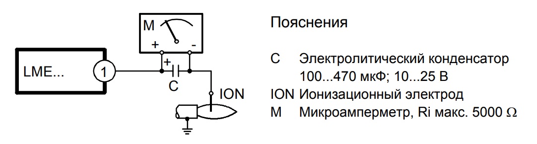
Контроль горения пламени осуществляется ультрафиолетовым датчиком пламени или ионизационным детектором.
При запуске и в процессе работы устройства осуществляется контроль давления воздуха, заключаемый в диагностике работоспособности реле давления.
Информационная система через многоцветную индикацию сигнализирует о причинах неполадок.
Достоинства:
- распознавание пониженного напряжения;
- управление горелками Baltur высокой тепловой мощности;
- встроенный цифровой монитор;
- электрическая дистанционная разблокировка;
- цифровая обработка сигналов;
- контроль герметичности газовых клапанов;
- информативность сигнальных сообщений;
- контроль давления воздуха;
- 10-летний ресурс.
Компания «АНКАС» предлагает купить менеджер горения Siemens для газовых горелок LME73.000A2 – современный микропроцессорный модуль с достойными характеристиками, широким функционалом и приемлемой ценой. Узнать подробности можно у консультанта интернет-магазина.
- Оплата онлайн
Оплатить заказ можно у нас на сайте, оформив заказа через корзину. - При получении
Оплатить заказ банковским переводом или наличными в пунктах самовывоза. При оплате «при получении» товар резервируется на 24ч. За подробной информацией обращайтесь к нашим специалистам по тел. +7 (495)131-57-49 - Безналичным платежом от ЮЛ
Оплатить заказ можно от ЮЛ по выставленному счету либо договору. Все товары и услуги реализуются с НДС. При отгрузке необходимо иметь доверенность или печать получателя. - Банковским переводом от ФЛ
Оплатить заказ можно в любом банке по счету, выставленному на Ваше имя. Запросите счет у менеджера, распечатайте его, произведите оплату в течении трех рабочих дней и ожидайте доставку. - Оплата картой по СБП
Система быстрых платежей ЦБ России позволяет производить оплату по QR коду или с помощью кнопки “Оплатить через СБП” на мобильном устройстве.
Контакты
Если вы хотите узнать наличие на складе, цену товара или задать
интересующий вас вопрос, напишите нам письмо через форму обратной связи или по телефону.
Наши специалисты обязательно свяжутся с вами в сжатые сроки.
Телефон:
+7 (495)131-57-49
Email:
sales@gtksnab.ru
Адрес:
г. Москва, ул. Новопоселковая, д. 6, кор. 217
Метро:
Сходненская
Режим работы:
Пн-Чт: 09:00 — 18:00, Пт: 09:00 — 17:00
| Москва и МО | Регионы | |
|---|---|---|
| Самовывоз | Самовызов осуществляется по городу Москва по адресу Новопоселковая 6, к217 Пн-Чт с 10.00 — до 17.00, Пт до 16.00. При оформлении заказа до 14.00, возможен самовывоз день в день. | |
| ТК «Деловые линии» | Стоимость доставки по Москве и Московской области до двери составляет 650 руб. Сроки поставки по Москве и Московской области от 1 до 5 дней. | Стоимость доставки в любой регион до ближайшего терминала 850 руб. Сроки поставки в регионы уточняйте у наших менеджеров по тел. +7 (495)131-57-49 или на сайте «Деловых линий». |
| Экспресс доставка | Экспресс доставка осуществляется компанией «Яндекс GO». Стоимость 990 руб. | Не осуществляется. |
*Если вы хотите воспользоваться другой транспортной компанией, свяжитесь с нашими менеджерами по тел. +7 (495)131-57-49

Пункт выдачи Лавка.Gtksnab
Адрес: г. Москва, ул. Новопоселковая, д. 6, кор. 217
Режим работы: Пн-Чт: 09:00 — 18:00, Пт: 09:00 — 17:00
Работая с этим сайтом, Вы даете свое согласие на использование
файлов cookie. Это необходимо для нормального функционирования сайта и анализа трафика. Подробнее…
Все права защищены © 2011 — 2022 , LAVKA.GTKSNAB.RU
- Главная
- Каталог
-
Корзина
-
0
Избранное - Контакты
Автомат горения Siemens LME73.000A2 управляет одно или двухступенчатыми газовыми горелками или газовыми горелками малой и средней мощности, с нагнетателем или без него в повторно-кратковременном режиме работы горелки.
Контроль пламени производится при помощи ионизационного датчика пламени или датчика пламени QRA с дополнительным устройством AGQ3.xA27 для газовых наддувных горелок или при голубом пламени с помощью датчика голубого пламени QRC.
Особенности автомата горения LME73.000A2:
- Сделаны европейскому стандарту EN 676: автоматические горелки с нагнетателем для газообразного топлива
- Обнаружение пониженного напряжения
- Контролиоль давления воздуха при помощи проверки реле давления во время запуска и в течении работы
- Удаленная электрическая деблокировка
- Разноцветная индикация сообщений
- Сообщения об ошибках
- Ограничение количества повторов
- Прецизионное управление с помощью цифровой обработки сигнала
- Контролирование повторяющегося-кратковременного режима не более, чем через 24 часа непрерывной работы
- Контролируются все цифровые входы и выходы, важные для обеспечения безопасности (производится с помощью сети сигналов обратной связи с контактов)
- Любое допустимое монтажное положение
Основные технические характеристики LME73.000A2:
| Напряжение питания, В | 230 |
| Потребляемая мощность | 12 ВА |
| Класс защиты IP | IP40 |
| Время реакции при пропадании пламени | 1 сек. |
| Диапазон рабочей температуры | -20 … +60 C |
Подробные технические характеристики можно посмотреть в соответствующем разделе выше.
Автомат LME21.330C2 изготовлен из ударопрочной, термо-огнестойкой пластмассы.
Состав автомата горения:
-
Корпус
-
Цоколь
В корпусе устанолены:
- Микро-контроллер с программой управления и реле нагрузки
- Кнопка разблокировки с многоцветной лампой отправки рабочих сообщений и сообщений об ошибках.
- Разъем интерфейса для OCI400 или удлинителя разблокирующей кнопки AGK20
Схема измерения тока для автомата горения LME73.000A2: