-
Contents
-
Table of Contents
-
Troubleshooting
-
Bookmarks
Quick Links
Operating Instructions Edition 04/2005
sinamics
SINAMICS G110
Related Manuals for Siemens SINAMICS G110
Summary of Contents for Siemens SINAMICS G110
-
Page 1
Operating Instructions Edition 04/2005 sinamics SINAMICS G110… -
Page 2: Installation
Parameter List The Parameter List contains a detailed description of all Parameters relating to the SINAMICS G110 and is structured in numerical order. Catalogues In the catalogue you will find all the necessary information to select an appropriate inverter,…
-
Page 3: Commissioning
Overview Installation Commissioning SINAMICS G110 Using the 120 W — 3 kW SINAMICS G110 System Parameters Operating Instructions Troubleshooting User Documentation Specifications Options Electro-Magnetic Compatibility Appendices Inverter Type Firmware Version SINAMICS G110 1.0 &1.1 (See Page 4) Index Issue 04/2005…
-
Page 4: Issue
04/2005 6.1 Troubleshooting with Standard Inverter LED — timings of LED has been updated. Approved Siemens Quality for Software and Training Other functions not described in this document may be is to DIN ISO 14001, Reg. No. 2160-01 available. However, this fact shall not constitute an obligation to supply such functions with a new control, or when servicing.
-
Page 5
Customers can access technical and general information at: http://www.siemens.de/sinamics-g110 Contact address Should any questions or problems arise while reading this manual, please contact the Siemens office concerned using the form provided at the back this manual. SINAMICS G110 Operating Instructions 6SL3298-0AA11-0BP0… -
Page 6
50 volts. This connection is normally used to ground the inverter. — Is the ground connection where the reference voltage can be the same as the Earth voltage. This connection is normally used to ground the motor. SINAMICS G110 Operating Instructions 6SL3298-0AA11-0BP0… -
Page 7
Please read the information carefully, since it is provided for your personal safety and will also help prolong the service life of your SINAMICS G110 Inverter and the equipment you connect to it. General… -
Page 8
(IEC 536 Class 1, NEC and other applicable standards). If a Residual Current-operated protective Device (RCD) is to be used, it must be an RCD type B. However, if the SINAMICS G110 inverter is connected to a single-phase grounded-neutral star mains network, an RCD of type A is permissible. -
Page 9
60204, 9.2.5.4) Repair WARNINGS Repairs on equipment may only be carried out by Siemens Service, by repair centers authorized by Siemens or by qualified personnel who are thoroughly acquainted with all the warnings and operating procedures contained in this manual. -
Page 10
Safety Instructions 04/2005 SINAMICS G110 Operating Instructions 6SL3298-0AA11-0BP0… -
Page 11: Table Of Contents
OFF and Braking Functions………………61 Control Modes (P1300)………………. 62 Faults and Alarms ………………..62 System Parameters ………………..63 Introduction to SINAMICS G110 System Parameters ……….63 Parameter Overview ………………..64 Troubleshooting………………..65 Troubleshooting with the Standard Inverter LED………… 65 Troubleshooting with the BOP …………….65 SINAMICS G110 Specifications …………….
-
Page 12
Removal of ‘Y’ Capacitor Link …………….79 DIN Rail Mounting Kit ………………. 80 Fitting the Basic Operator Panel …………….. 82 Description of the BOP ………………83 Applicable Standards ………………. 84 List of Abbreviations ……………….. 85 Index ……………………..87 SINAMICS G110 Operating Instructions 6SL3298-0AA11-0BP0… -
Page 13
Motor Overload PTC Connection ………………51 Figure 3-8 Typical Configurations of the Digital Output …………….. 52 Figure 4-1 Siemens standard control using ON/OFF1 and REV …………58 Figure 4-2 Siemens standard control using ON/OFF1 and ON_REV/OFF1 ………. 59 Figure 4-3 2-wire control using ON_FWD and ON_REV …………… -
Page 14
Overview 04/2005 SINAMICS G110 Operating Instructions 6SL3298-0AA11-0BP0… -
Page 15: Overview
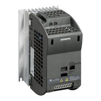
Comprehensive protective functions provide excellent inverter and motor protection. The SINAMICS G110 CPM110 with its default factory settings is ideal for a large range of simple V/f motor control applications. Using the comprehensive range of programmable parameters provided with the inverter, the unit can be adapted for a wide range of applications.
-
Page 16
150% overload for 60 seconds 2-wire/3-wire control Automatic restart after a mains failure Flying start Protection Characteristics Overvoltage/undervoltage protection Overtemperature protection for the inverter Ground fault protection Short-circuit protection t thermal motor protection Motor stall prevention SINAMICS G110 Operating Instructions 6SL3298-0AA11-0BP0… -
Page 17: Installation
(IEC 536 Class 1, NEC and other applicable standards). If a Residual Current-operated protective Device (RCD) is to be used, it must be an RCD type B. However, if the SINAMICS G110 inverter is connected to a single-phase grounded-neutral star mains network, an RCD of type A is permissible.
-
Page 18: Power Losses
XAP214-123456 Character 7 is a separator XAP214-123456 Characters 8-13 are the sequential serial number 1-999999 2.2 Power Losses For information on the typical power losses for the SINAMICS G110 inverter, please consult Table 7-6 on page 69. 2.3 Ambient operating conditions Temperature -10ºC to +50ºC (14ºF to 122ºF) see Table 7-8 on page 70 for derating information.
-
Page 19: Harmonic Currents
Ensure that the inverter’s air vents are not obstructed. For the recommended clearance distances see Figure 2-4 on page 22. 2.4 Harmonic Currents For details of the harmonic currents with relation to the SINAMICS G110 inverter, please see Table 9-1on page 74. 2.5 Derating with Pulse Frequencies For details of derating with pulse frequencies with relation to the SINAMICS G110 inverter, please refer to Table 7-8 on page 70.
-
Page 20: Mechanical Installation
CAUTION The control, power supply and motor leads must be laid separately. Do not feed them through the same cable conduit/trunking. Table 2-1 Dimensions of the SINAMICS G110 Inverter Overall Dimensions Drilling Dimensions Depth with BOP fitted…
-
Page 21: Figure 2-3 Dimensions Of The Sinamics G110
04/2005 Installation Figure 2-3 Dimensions of the SINAMICS G110 SINAMICS G110 Operating Instructions 6SL3298-0AA11-0BP0…
-
Page 22: Figure 2-4 Clearance Distances For Mounting The Inverter
Installation 04/2005 Figure 2-4 Clearance distances for mounting the inverter Table 2-2 Mounting Tightening Torques of SINAMICS G110 Fixing Bolt (not supplied) Frame Size Tightening Torque of fixings Size 2.5 Nm (22.12 lbf.in) with washers fitted 4.0 Nm (35.40 lbf.in) with washers fitted…
-
Page 23: Electrical Installation
FSB and FSC can be used on ungrounded supplies, but it is necessary to cut the ‘Y’ capacitor link as described in Removal of ‘Y’ Capacitor Link on page 79. If an output phase is shorted to ground, the inverter may trip with F0001 (overcurrent). SINAMICS G110 Operating Instructions 6SL3298-0AA11-0BP0…
-
Page 24
Installation 04/2005 Operation with Residual Current Device If an RCD (also referred to as ELCB or RCCB) is fitted, the SINAMICS G110 inverters will operate without nuisance tripping, provided that: A type B RCD is used. If the SINAMICS G110 inverter is connected to a single-phase grounded-neutral star mains network, an RCD of type A is permissible. -
Page 25: Figure 2-5 Sinamics G110 Connection Terminals
04/2005 Installation Access to the power and motor terminals Figure 2-5 below show the layout of the SINAMICS G110 inverter’s control, power and motor connection terminals. Figure 2-5 SINAMICS G110 Connection Terminals Figure 2-6 SINAMICS G110 DC Terminals Connections SINAMICS G110…
-
Page 26
The following minimum cross-section for cables should be used when utilizing the DC terminals: ♦ FSA – 0.5 mm (20 AWG) ♦ FSB – 1.5 mm (16 AWG) ♦ FSC – 2.5 mm (12 AWG) SINAMICS G110 Operating Instructions 6SL3298-0AA11-0BP0… -
Page 27: Figure 2-7 Motor And Power Connections
Use screened or armored cables for the motor connections and ground the screen at both ends using the cable clamps For EMC compliant installation using the DIN Rail Mounting Kit, please refer to Appendix B on page 80. SINAMICS G110 Operating Instructions 6SL3298-0AA11-0BP0…
-
Page 28: Figure 2-8 Wiring Guidelines To Minimize The Effects Of Emi
Wiring Guidelines to Minimize the Effects of EMI Legend Motor cable Use suitable clips to fix motor and control cable screens securely to metal back plate Mains power cable Retaining screw (inverter fixing bolts) Line commutating Choke Control cable SINAMICS G110 Operating Instructions 6SL3298-0AA11-0BP0…
-
Page 29: Sinamics G110 Flat Plate Variant
5. It is recommended that the mounting area of the rear plate has to be, as a minimum, at least the same area of the flat plate on the inverter. 6. Side by side or stacked mounting is not allowed for the SINAMICS G110 Flat Plate inverter.
-
Page 30: Table 2-3 Flat Plate Power Losses And Thermal Specifications
Total losses (W) Lineside and control losses (W) Recommended thermal resistance of heatsink (K/W) Recommended output current (A) *The losses given in Table 2-3 are applicable for units fitted with 25 m of screened cable SINAMICS G110 Operating Instructions 6SL3298-0AA11-0BP0…
-
Page 31: Commissioning
3 Commissioning This section describes the different methods of how to commission and run the SINAMICS G110 inverter. A prerequisite is that the mechanical and electrical installation has been completed as described in Section 2, starting on page 17 of these Operating Instructions.
-
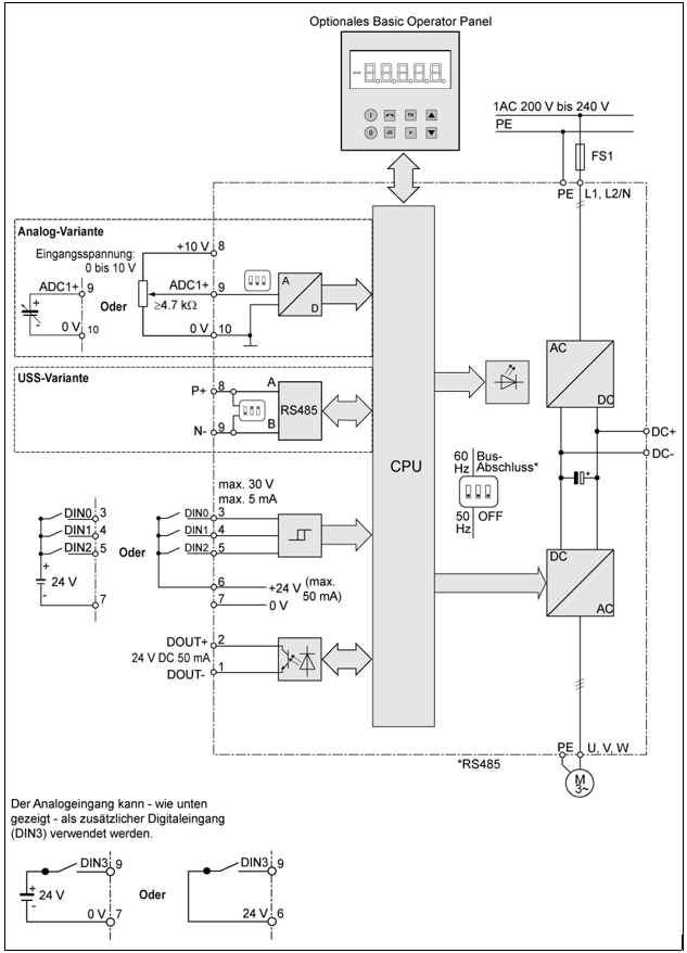
Page 32: Block Diagram
Commissioning 04/2005 3.1 Block Diagram Figure 3-1 Inverter block diagram SINAMICS G110 Operating Instructions 6SL3298-0AA11-0BP0…
-
Page 33: Commission Modes
MLFBs listed in Table 7-4 and Table 7-5 on pages 68 and 69 respectively. Since the SINAMICS G110 is available in two variants; different options for the commissioning of the inverters are available to the user. These commissioning options are described in the following sections covering the ‘Basic Commissioning’…
-
Page 34: Basic Commissioning
Ramp-up time / Ramp-down time = 10 s. Changing the motor base frequency The default motor base frequency of the SINAMICS G110 inverter is 50 Hz. In some parts of the world motors are designed for a base frequency of 60 Hz.
-
Page 35: Figure 3-3 Basic Operation — Analog And Uss Variants
3.3.1 Factory Settings The inverter has already been programmed at the factory for standard V/f applications on a Siemens standard four-pole 3-phase induction motor, that has the same power rating as the inverters. Controlling the speed of the motor is accomplished by connecting the analog inputs…
-
Page 36: Table 3-2 Factory Settings For Operation Using The Standard Inverter (Uss Variant)
Warnings and faults states on the inverter The LED indicates the operating status of the inverter. The LED also indicate various warnings or fault states. In section 6.1 on page 65, the inverter states indicated by the LED are explained. SINAMICS G110 Operating Instructions 6SL3298-0AA11-0BP0…
-
Page 37: Figure 3-4 Bop
04/2005 Commissioning Bus termination on USS variant The USS variant of the SINAMICS G110 inverter uses RS485 protocols to communicate with the controlling system and all other inverters connected to the network. It is necessary to terminate the last inverter on the network bus. This is achieved by setting the Bus Termination DIP switches on the front of the inverter to the ‘Bus…
-
Page 38: Figure 3-5 Changing Parameters Via The Bop
Press to confirm and store the value Press until r0000 is displayed Press to return the display to the standard drive display (as defined by the customer) Figure 3-5 Changing parameters via the BOP SINAMICS G110 Operating Instructions 6SL3298-0AA11-0BP0…
-
Page 39
5. Stop the motor by pressing the button. If the BOP has been set as the command source (P0700 = 1 or P0719 = 10 — 15), the inverter will stop if the BOP is removed. SINAMICS G110 Operating Instructions 6SL3298-0AA11-0BP0… -
Page 40: Advanced Commissioning
An overview is given in Table 3-3 on page 41. The modes are described in detail in the following sections. Note The SINAMICS G110 inverter can be connected in more than one mode at any time, for example, the BOP is attached, USS used and switches connected to terminals.
-
Page 41
Note Both variants will require (PC to Inverter Connection Kit) if operated in mode SERIAL (USS-RS232). The hardware setup for SERIAL (USS-RS232) mode can also be used for STARTER mode which additionally requires (STARTER software). SINAMICS G110 Operating Instructions 6SL3298-0AA11-0BP0… -
Page 42
Basic Operator Panel (BOP). The BOP allows the user direct access to the parameters of the SINAMICS G110 inverter. With the BOP attached to the inverter, the user can perform the following functions:… -
Page 43
P1000 = 5 for complete inverter control when in STARTER mode. Note When downloading parameter sets associated with different firmware releases using the STARTER tool, it should be noted that for the new parameters, the default value is entered. SINAMICS G110 Operating Instructions 6SL3298-0AA11-0BP0… -
Page 44
NOTES The frequency setpoint (P1000) and the command source (P0700) have both to be set correctly to operate the SINAMICS G110 inverter. Alternatively, P0719 can be set to a specific frequency setpoint and command source. Frequency setpoint and command source can be derived from different modes (e.g. -
Page 45
Commissioning 3.4.3 Changing the Motor Base Frequency The default motor base frequency of the SINAMICS G110 inverter is 50 Hz. In some parts of the world motors are designed for a base frequency of 60 Hz. Changing the inverter motor base frequency is accomplished using three methods: A DIP switch is provided on the front of the inverter to select the required base frequency (see Section 3.3 on page 34). -
Page 46: Figure 3-6 Typical Motor Rating Plate Example
04/2005 3.4.4 Quick Commissioning (P0010=1) Quick commissioning is an easy way to optimally configure the SINAMICS G110 inverter to a specific motor. The motor data, taken from the motor rating label, is entered into the inverter and then the inverter calculates the dependent control and protection parameters.
-
Page 47
Parameter List. Changing motor parameters is not possible unless P0010=1. Ensure that the motor is configured correctly to the inverter, i.e. in the above example delta terminal connection is for 230 V. SINAMICS G110 Operating Instructions 6SL3298-0AA11-0BP0… -
Page 48
1. Motor related parameters — please refer to the motor rating plate. 2. Denotes parameters that contain more detailed lists of possible settings for use in specific applications. Please refer to the Parameter List. SINAMICS G110 Operating Instructions 6SL3298-0AA11-0BP0… -
Page 49: Figure 3-7 Motor Overload Ptc Connection
If the optocoupler is used to drive an auxiliary relay, make sure there is a commutation diode or a similar device to absorb the inductive energy. If the optocoupler is used to drive an LED, make sure that the current is limited by means of a resistor. SINAMICS G110 Operating Instructions 6SL3298-0AA11-0BP0…
-
Page 50: Figure 3-8 Typical Configurations Of The Digital Output
50 mA max. Relay Driver LED Driver G110 +24V +24V G110 I0.0 I0.1 PLC Control PLC Control Using internal 24V & 0V ref. Using external 24V & 0V ref. Figure 3-8 Typical Configurations of the Digital Output SINAMICS G110 Operating Instructions 6SL3298-0AA11-0BP0…
-
Page 51
Perform a factory reset. 21. The BOP can now be removed from the inverter. The following important restrictions should be considered when using the Cloning procedure: Only the current dataset is uploaded to the BOP. SINAMICS G110 Operating Instructions 6SL3298-0AA11-0BP0… -
Page 52
If the download or upload of data fails, the inverter will not function correctly. Note 1. After cloning parameters between differing variants of the SINAMICS G110 inverters (i.e. Analog to USS or USS to Analog) the following parameter must be checked: P0719 –… -
Page 53: Using The Sinamics G110
This equipment must not be used as an ‘emergency stop mechanism’ (see EN 60204, 9.2.5.4) 4.1 Frequency Setpoint (P1000) This parameter determines where the control signal for the frequency setpoint is obtained. The SINAMICS G110 has two default settings depending on the inverter variant. Analog Variant Default Value: 2 –…
-
Page 54: Command Sources (P0700)
4.2 Command Sources (P0700) This parameter determines from which source the inverter receives the Start, Stop and Reverse commands. The SINAMICS G110 has two default settings depending on the inverter variant, see the Quick Commissioning Flowchart on page 48. NOTES The ramp times and ramp-smoothing functions also affect how the motor starts and stops.
-
Page 55: Types Of Control Using The Terminals
The different types of control are enabled using parameter P0727 and selecting one of the following options: Default value: P0727 = 0: Siemens standard control (ON/OFF1, REV) Other settings: P0727 = 1: 2-wire control (ON_FWD, ON_REV) P0727 = 2: 3-wire control (FWDP, REVP, STOP)
-
Page 56: Figure 4-1 Siemens Standard Control Using On/Off1 And Rev
The REV command initiated by itself cannot start the motor. ON/OFF1 ON/OFF1 Equivalent Control Inputs Active ON/OFF1 Control Commands Active Active Inverter Frequency Time f out o = OFF1 Figure 4-1 Siemens standard control using ON/OFF1 and REV SINAMICS G110 Operating Instructions 6SL3298-0AA11-0BP0…
-
Page 57: Figure 4-2 Siemens Standard Control Using On/Off1 And On_Rev/Off1
Without any control signal enabled the drive will ramp down to a stop and remain at standstill. ON/OFF1 ON/OFF1 ON_REV/OFF1 ON_REV/OFF1 Equivalent Control Inputs Ignored Act. Active ON/OFF1 Control Commands Active Ignored ON_REV/OFF1 Inverter Frequency Time f out o = OFF1 Figure 4-2 Siemens standard control using ON/OFF1 and ON_REV/OFF1 SINAMICS G110 Operating Instructions 6SL3298-0AA11-0BP0…
-
Page 58: Figure 4-3 2-Wire Control Using On_Fwd And On_Rev
Using the SINAMICS G110 04/2005 4.3.2 2-wire Logic (P0727=1) Overview This method uses two maintained signals, ON_FWD and ON_REV which start/stop the drive and determine the direction of the motor. The advantage of this method of control is that ON_FWD and ON_REV can be…
-
Page 59: Figure 4-4 3-Wire Control Using Fwdp, Revp And Stop
04/2005 Using the SINAMICS G110 4.3.3 3-wire Control (P0727=2) Overview This method uses three commands to control the operation of the motor: 1. STOP – Causes on OFF1 command to be performed by the inverter. 2. FWDP – Causes the motor to run in a forward direction (run right).
-
Page 60: Figure 4-5 3-Wire Control Using On_Pulse, Off1/Hold And Rev
Using the SINAMICS G110 04/2005 4.3.4 3-wire Control (P0727=3) Overview There are three signals associated with this function: 1. OFF1/HOLD – Being maintained closed the opening of the contact will switch the drive OFF and cause a ramp down to 0 Hz.
-
Page 61: Off And Braking Functions
04/2005 Using the SINAMICS G110 4.4 OFF and Braking Functions 4.4.1 OFF1 This command (produced by canceling the ON command) causes the inverter to come to a standstill at the selected ramp-down rate. Parameter to change ramp-down time see P1121 NOTES ON and the following OFF1 command must have the same source.
-
Page 62: Control Modes (P1300)
♦ DC braking is active. 4.5 Control Modes (P1300) The various modes of operation of the SINAMICS G110 control the relationship between the speed of the motor and the voltage supplied by the inverter. A summary of the control modes available are listed below:…
-
Page 63: System Parameters
04/2005 System Parameters 5 System Parameters 5.1 Introduction to SINAMICS G110 System Parameters The parameters can only be changed by using the optional Basic Operator Panel (BOP) or the Serial Interface. Parameters can be changed and set using the optional BOP to adjust the desired properties of the inverter, such as ramp times, minimum and maximum frequencies etc.
-
Page 64: Parameter Overview
System Parameters 04/2005 5.2 Parameter Overview Figure 5-1 Parameter Overview For a comprehensive description of all the parameters, please consult the SINAMICS G110 Parameter List. SINAMICS G110 Operating Instructions 6SL3298-0AA11-0BP0…
-
Page 65: Troubleshooting
Troubleshooting 6 Troubleshooting WARNINGS Repairs on equipment may only be carried out by Siemens Service, by repair centers authorized by Siemens or by authorized personnel who are thoroughly acquainted with all the warnings and operating procedures contained in this manual.
-
Page 66
DIN0 was, in fact, set-up for the ON command. In the case of ON/OFF control via the RS485 bus (USS protocol) the relevant bit (bit 02) of status word 1 (r0052) can be found in the following position: SINAMICS G110 Operating Instructions 6SL3298-0AA11-0BP0… -
Page 67: Sinamics G110 Specifications
04/2005 SINAMICS G110 Specifications 7 SINAMICS G110 Specifications Table 7-1 SINAMICS G110 Performance Ratings Feature Specification Mains operating voltage 200 V to 240 V (±10%) 1AC 120 W to 3.0 kW and power ranges Input frequency 47 to 63 Hz…
-
Page 68: Table 7-2 Control Terminals Screwless Type – Wire Sizes
16 – 12 16 – 12 16 – 12 The horsepower (hp) ratings are obtained by comparison to the Siemens 1LA6 and 1LA7 motors and not NEMA/UL rated motors. Current data applies for an ambient temperature of 50ºC unless otherwise specified The value applies to the rated mains voltage of 230 V * Indicates the last digit of the Order No.
-
Page 69: Table 7-5 Frame Sizes B And C
14 – 10 12 – 8 12 – 8 The horsepower (hp) ratings are obtained by comparison to the Siemens 1LA6 and 1LA7 motors and not NEMA/UL rated motors. Current data applies for an ambient temperature of 50ºC unless otherwise specified The value applies to the rated mains voltage of 230 V * Indicates the last digit of the Order No.
-
Page 70: Table 7-8 Derating With Pulse Frequencies
SINAMICS G110 Specifications 04/2005 Table 7-7 Harmonic currents Single Phase 230 V Rated Output Fundamental (kW) Amps Amps Amps Amps Amps Amps Amps 0.12 1.18 1.05 0.76 0.58 0.568 0.508 0.25 2.26 2.06 1.77 1.50 1.32 1.20 1.02 0.37 3.19 2.26…
-
Page 71: Options
04/2005 Options 8 Options The following accessories are available as options for your SINAMICS G110 Inverter. For more details please refer to the catalogue or contact your local Siemens sales office if you require assistance. Variant Dependent Options Supplementary filter for Class B operation…
-
Page 72
Options 04/2005 SINAMICS G110 Operating Instructions 6SL3298-0AA11-0BP0… -
Page 73: Electro-Magnetic Compatibility (Emc)
European government organization. This approach allows the use of standards that are still in preparation. Note The SINAMICS G110 inverter is designed to be used only by professional end users with EMC knowledge. It is not designed for users that do not have EMC knowledge.
-
Page 74: Table 9-1 Harmonic Currents
EN 61000-3-2 «Limits for harmonic current emissions (equipment input <= 16A per phase)». All Siemens variable speed drives of the SINAMICS G110 range, which are classified as «Professional Equipment» within the terms of the standard, fulfill the requirements of the standard.
-
Page 75: Table 9-2 Case 1 — General Industrial
8 kV air discharge 2 kV power cables (Level 3), 2 kV control Burst Interference EN 61000-4-4 (Level 4) Radio Frequency 80-1000 MHz, 10 V/m, 80% AM, power and Electromagnetic Field, EN 61000-4-3 signal lines amplitude modulated SINAMICS G110 Operating Instructions 6SL3298-0AA11-0BP0…
-
Page 76: Table 9-4 Case 3 — Filtered For Residential, Commercial And Light Industry
* These limits are dependent on the inverter being correctly installed inside a metallic switchgear enclosure. The limits will not be met if the inverter is not enclosed. NOTE To achieve these performance levels, you must not exceed the default Pulse frequency. SINAMICS G110 Operating Instructions 6SL3298-0AA11-0BP0…
-
Page 77: Table 9-5 Compliance Table
Category C1: Power Drive System (PDS) of rated voltage less than 1000V, intended for use in the first environment. SINAMICS G110 Operating Instructions 6SL3298-0AA11-0BP0…
-
Page 78
Electro-Magnetic Compatibility (EMC) 04/2005 SINAMICS G110 Operating Instructions 6SL3298-0AA11-0BP0… -
Page 79: A Removal Of ‘Y’ Capacitor Link
Removal of ‘Y’ Capacitor Link Removal of ‘Y’ Capacitor Link To use the SINAMICS G110 FSB and FSC on ungrounded supplies the ‘Y’ capacitor (cap) link must be removed as follows: 1. Ensure the inverter has been disconnected from all power supplies.
-
Page 80: Bdin Rail Mounting Kit
DIN Rail Mounting Kit 04/2005 DIN Rail Mounting Kit The DIN Rail Mounting Kit is an optional accessory for the SINAMICS G110 inverter. It must be ordered as a separate item using the following Order Numbers: For FSA: 6SL3261-1BA00-0AA0. For FSB: 6SL3261-1BB00-0AA0.
-
Page 81
04/2005 DIN Rail Mounting Kit 4. Holding the front of the inverter, pull the inverter forward and upwards to release it from the DIN rail. Figure B-1 Installing the DIN Rail Mounting Kit (FSA) SINAMICS G110 Operating Instructions 6SL3298-0AA11-0BP0… -
Page 82: C Fitting The Basic Operator Panel
Fitting the Basic Operator Panel 04/2005 Fitting the Basic Operator Panel SINAMICS G110 Operating Instructions 6SL3298-0AA11-0BP0…
-
Page 83: Description Of The Bop
Fn button will return you to your starting point. Access Pressing this button allows access to the parameters. parameters Increase Pressing this button increases the displayed value. value Decrease Pressing this button decreases the displayed value. value SINAMICS G110 Operating Instructions 6SL3298-0AA11-0BP0…
-
Page 84: E Applicable Standards
Safety of machinery — Electrical equipment of machines European EMC Directive When installed according to the recommendations described in this manual, the SINAMICS G110 fulfils all requirements of the EMC Directive as defined by the EMC Product Standard for Power Drive Systems EN61800-3. Underwriters Laboratories…
-
Page 85: F List Of Abbreviations
Power drive system Programmable logic controller Parameter list Positive-Negative-Positive Transistor Type Positive temperature coefficient Quick commissioning RCCB Residual current circuit breaker Residual current device Ramp function generator Radio-frequency interference Revolutions per minute Universal serial interface Variable torque SINAMICS G110 Operating Instructions 6SL3298-0AA11-0BP0…
-
Page 86
List of Abbreviations 04/2005 SINAMICS G110 Operating Instructions 6SL3298-0AA11-0BP0… -
Page 87: Index
04/2005 Index Index Drill pattern for SINAMICS G110 · 21 2-wire control · 55 2-wire Logic · 58 Electrical Installation · 23 Electro-Magnetic Compatibility 3-wire control · 55 general · 73 3-wire Control · 59, 60 self-certification · 73 technical construction file · 73 Abbreviations ·…
-
Page 88
Index 04/2005 Serial · 42 Operation Shock · 18 starting and stopping the motor · 54, 61 Siemens standard Control · 56 Operation with SINAMICS G110 long cables · 24 available options · 71 Residual Current Device · 24 general · 15 ungrounded IT supplies ·… -
Page 89
Suggestions and/or Corrections Suggestions Siemens AG Corrections Automation & Drives Group For Publication/Manual: SD PM 4 P.O. Box 3269 SINAMICS G110 Operating Instructions D-91050 Erlangen Federal Republic of Germany Email: documentation.sd@siemens.com User Documentation From Operating Instructions Name: Order Number: Company/Service Department… -
Page 92
Siemens AG Automation & Drives Standard Drives © Siemens AG 2005 Postfach 3269, D – 91050 Erlangen Subject to change without prior notice Germany 6SL3298-0AA11-0BP0 www.siemens.com Printed in Germany…
Информация
Малогабаритная версия управления по эксплуатации оценивает огромную долю обычных приложений. Она реальная для преобразователей с версиями микропрограммного обеспечивания 1.0 и 1.1. Всю прочую доскональную информацию возможно получить из управления по эксплуатации и перечня характеристик.

| Клемма | Обозначение | Функция |
| 1 | DOUT- | Цифровой выход (-) |
| 2 | DOUT+ | Цифровой выход (+) |
| 3 | DIN0 | Цифровой вход 0 |
| 4 | DIN1 | Цифровой вход 1 |
| 5 | DIN2 | Цифровой вход 2 |
| 6 | — | Выход +24 В / макс. 50 мА |
| 7 | — | Выход 0 В |
| 8 | — | Выход +10 В RS485 P+ |
| 9 | ADC1 | Аналоговый вход RS485 N- |
| 10 | — | Выход 0 В |
Принципиальная схема
Заводские установки
Преобразователь SINAMICS G110 предустановлен на заводе для нормальных приложений U/f с 4-полюсным трехфазным асинхронным движком с рабочими чертами, схожими преобразователю.
| Источник команд | P0700 см. раздел 3.1/ 3.2 |
| Источник заданного значения | P1000 см. раздел 3.1/ 3.2 |
| Самовентилируемый двигатель | P0335 = 0 |
| Коэффициент перегрузки двигателя | P0640 = 150% |
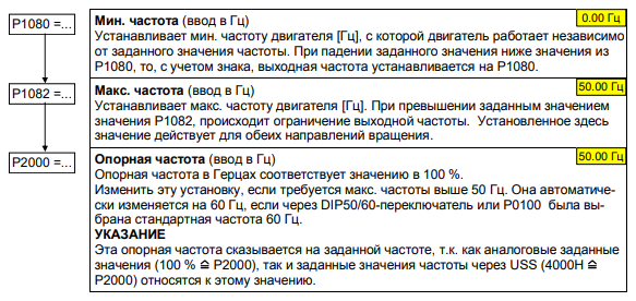
| Мин. частота | P1080 = 0 Гц |
| Макс. частота | P1082 = 50 Гц |
| Время разгона | P1120 = 10 сек |
| Время торможения | P1121 = 10 сек |
| Управление U/f | P1300 = 0 |
Своеобразные заводские установки для аналогового входа
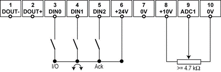
| Цифровые входы | Клеммы | Параметр | Функция |
| Источник команд | 3, 4, 5 | P0700 = 2 | Цифровой вход |
| Источник заданного значения | 9 | P1000 = 2 | Аналоговый вход |
| Цифровой вход 0 | 3 | P0701 = 1 | ВКЛ / ВЫКЛ1 (I/O) |
| Цифровой вход 1 | 4 | P0702 = 12 | Реверсирование |
| Цифровой вход 2 | 5 | P0703 = 9 | Квитирование ошибок (Ack) |
| Метод управления | — | P0727 = 0 | Стандартное управление Siemens |
Внешний вид панели управления
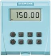
| Панель управления/клавиша | Функция | Действия |
| Индикациясостояния | LCD демонстрирует установки, с которыми преобразователь трудится в аутентичный момент. | |
| Запустить двигатель | Нажатием данной кнопки запускается преобразователь. В предустановке данная кнопка деактивирована. Активация клавиши: P0700 = 1 или P0719 = 10 … 15 | |
| Остановить двигатель | OFF1 Нажатие этой кнопки останавливает двигатель на выбранное время торможения. Деактивирована через предустановку. Активация клавиши: P0700 = 1 или P0719 = 10 … 15 ВЫКЛ2 Двукратное нажатие (или однократное длительное нажатие) клавиши вызывает свободный выбег двигателя до состояния покоя. Эта функция активирована всегда. |
|
| Реверсирование | Нажмите эту кнопку, чтобы изменить направление вращения двигателя. отображается знаком минус (-) или мигающей десятичной точкой. Активация клавиши: P0700 = 1 или P0719 = 10 … 15. | |
| Периодический режим работы двигателя | В состоянии „Включен/готов“ нажатие данной кнопки вызывает пуск и вращение мотора с предустановленной частотой шага. При отпускании кнопки движок замирает. Нажатие данной кнопки при вращающемся движке остается без результатов. | |
| Функции | С помощью этой клавиши можно вывести на экран дополнительную информацию. Если во время работы клавиша нажата в течение двух секунд, то независимо от соответствующего параметра отображается следующая информация: Напряжение звена постоянного тока (обозначается символом d — единица измерения В). Выходная частота (Гц) Выходное напряжение (обозначается o — единица измерения В). Значение, выбранное в P0005 (если P0005 настроен на отображение одного из у.е. данных. (от 1 до 3), соответствующее значение больше не появится). При повторном нажатии вышеуказанные индикаторы последовательно меняются. Находясь в любом параметре (rxxxxx или Pxxxxx), кратковременное нажатие клавиши Fn приведет вас непосредственно к r0000. Затем можно изменить следующий параметр по мере необходимости. После возврата к r0000 нажатие клавиши Fn возвращает вас в исходную точку. Подтверждение Если появляются предупреждения и сообщения об ошибках, их можно подтвердить, нажав клавишу Fn. | |
| Доступ к параметрам | Нажатием этой клавиши можно обращаться к параметрам. |
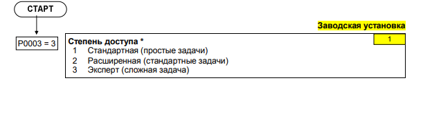
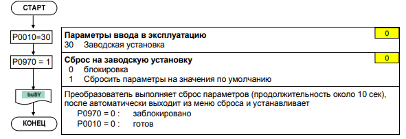
Ввод в эксплуатацию
Быстрый ввод в эксплуатацию
Быстрый запуск позволяет согласовать инвертор с двигателем и установить важные параметры процесса. Если используется 4-полюсный стандартный двигатель Siemens 1LA7, соответствующий данным заводской таблички преобразователя, не проводите быстрый запуск.
Для доступа ко всем параметрам двигателя рекомендуется уровень доступа P0003=3 (5.2).
Параметры, отмеченные *, имеют больше вариантов настройки, чем указано здесь. Другие варианты настройки м. в списке параметров.
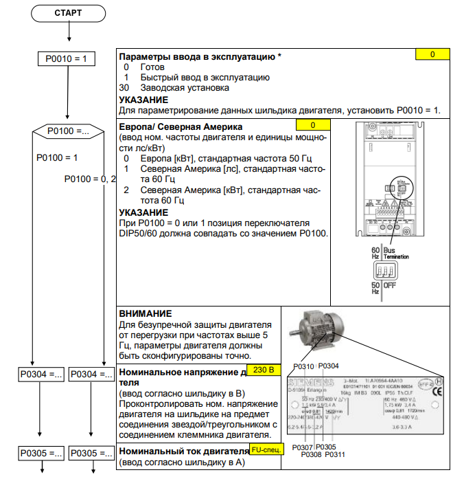
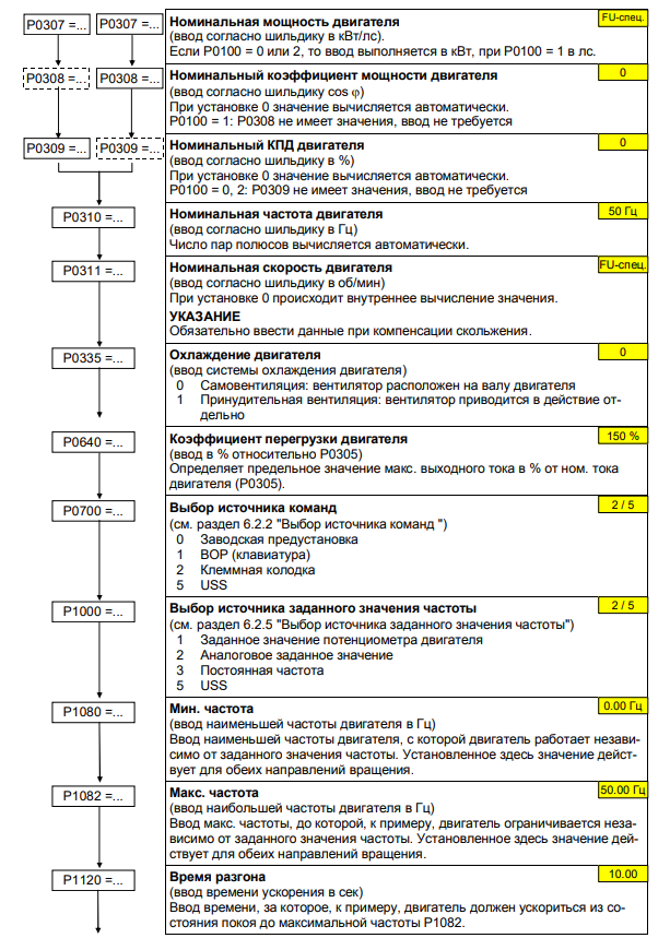
Прикладной ввод в эксплуатацию
Ввод в эксплуатацию используется для адаптации/оптимизации комбинации инвертор/двигатель к условиям эксплуатации. Инвертор имеет множество функций, не все из которых необходимы для конкретного применения. Эти функции могут быть опущены при запуске приложения. Здесь описано большинство возможных функций; другие функции. см. список параметров. Список параметров.
Параметры, отмеченные *, имеют больше вариантов конфигурации, чем те, которые перечислены здесь. Другие параметры настройки м. в списке параметров.
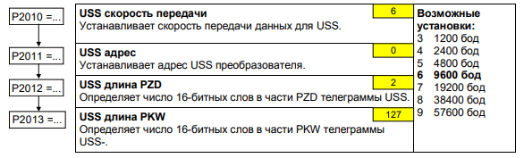
Последовательный интерфейс (USS)
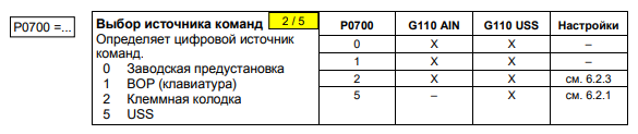
Выбор источника команд
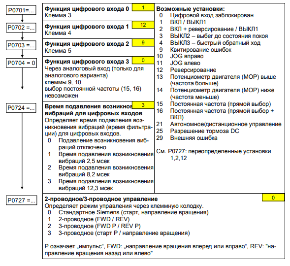
Цифровые входы (DIN)
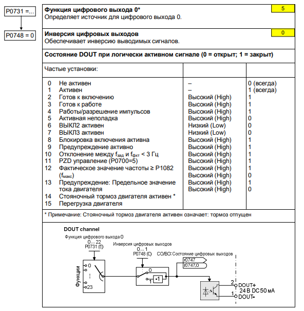
Цифровой выход (DOUT)
Выбор источника заданного значения частоты
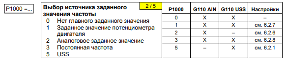
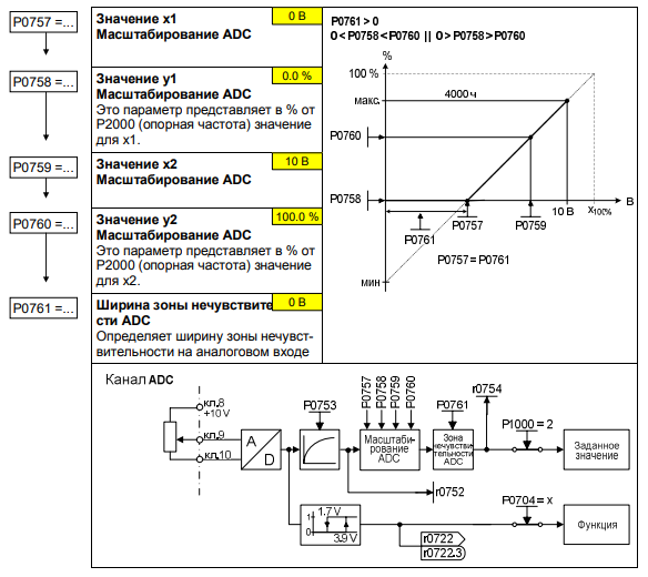
Аналоговый вход (ADC)
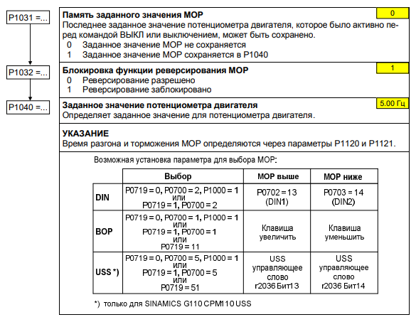
Потенциометр двигателя (MOP)
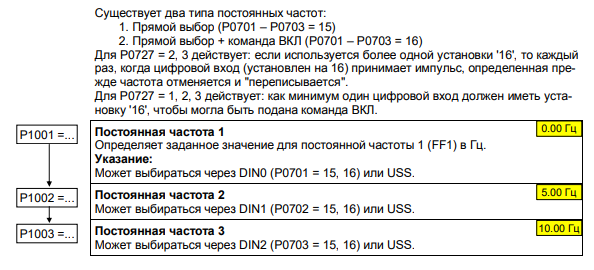
Постоянные частоты (FF)
Исходные/граничные частоты
Управление двигателем
Защита преобразователя/двигателя
Стояночный тормоз двигателя
Тормоз DC смешанный тормоз
Регулятор VDC
Сброс параметров к заводским установкам
Список ошибок
| Ошибка | Значение |
| F0001 | Ток перегрузки |
| F0002 | Перенапряжение |
| F0003 | Пониженное напряжение |
| F0004 | Перегрев преобразователя |
| F0005 | Преобразователь I2t |
| F0011 | Перегрев двигателя I2t |
| F0051 | Ошибка параметров EEPROM |
| F0052 | Ошибка питания |
| F0060 | Переполнение слотов Asic |
| F0072 | Ошибка заданного значения USS |
| F0085 | Внешняя ошибка |
| Предупреждения | Значение |
| A0501 | Предельное значение тока |
| A0502 | Предельное значение перенапряжения |
| A0503 | Предельное значение пониженного напряжения |
| A0505 | Преобразователь I2t |
| A0511 | Перегрев двигателя I2t |
| A0910 | Регулятор Vdc-макс отключен |
| A0911 | Регулятор Vdc-макс активен |
| A0920 | Параметры ADC установлены неправильно |
| A0923 | Как JOG влево, так и JOG вправо запрошены |
Скачать документацию.
RU
- Manuals
- Brands
- Siemens Manuals
- DC Drives
- SINAMICS G110
Manuals and User Guides for Siemens SINAMICS G110. We have 3 Siemens SINAMICS G110 manuals available for free PDF download: Operating Instructions Manual, Manual

Siemens SINAMICS G110 Operating Instructions Manual (92 pages)
120 W — 3 kW
Brand: Siemens
|
Category: DC Drives
|
Size: 1.46 MB
Table of Contents
-
Installation
2
-
Commissioning
3
-
Issue
4
-
Table of Contents
11
-
1 Overview
15
-
The SINAMICS G110
15
-
Features
15
-
-
2 Installation
17
-
General
17
-
Figure 2-1 Reforming Capacitors after a Period of Storage
17
-
Power Losses
18
-
Ambient Operating Conditions
18
-
Figure 2-2 Derating for Altitude
18
-
Harmonic Currents
19
-
Derating with Pulse Frequencies
19
-
Overvoltage and Trip Levels
19
-
Overcurrent Trip Levels
19
-
Mechanical Installation
20
-
Table 2-1 Dimensions of the SINAMICS G110 Inverter
20
-
Figure 2-3 Dimensions of the SINAMICS G110
21
-
Figure 2-4 Clearance Distances for Mounting the Inverter
22
-
Table 2-2 Mounting Tightening Torques of SINAMICS G110
22
-
Electrical Installation
23
-
Figure 2-5 SINAMICS G110 Connection Terminals
25
-
Figure 2-6 SINAMICS G110 DC Terminals Connections
25
-
Figure 2-7 Motor and Power Connections
27
-
Figure 2-8 Wiring Guidelines to Minimize the Effects of EMI
28
-
SINAMICS G110 Flat Plate Variant
29
-
Figure 2-9 SINAMICS G110 Flat Plate Variant
29
-
Table 2-3 Flat Plate Power Losses and Thermal Specifications
30
-
-
3 Commissioning
31
-
Block Diagram
32
-
Figure 3-1 Inverter Block Diagram
32
-
Commission Modes
33
-
Basic Commissioning
34
-
Figure 3-2 Motor Base Frequency DIP Switch and Bus Termination
34
-
Figure 3-3 Basic Operation — Analog and USS Variants
35
-
Table 3-1 Factory Settings for Operation Using the Standard Inverter (Analog Variant)
35
-
Table 3-2 Factory Settings for Operation Using the Standard Inverter (USS Variant)
36
-
Figure 3-4 BOP
37
-
Figure 3-5 Changing Parameters Via the BOP
38
-
Advanced Commissioning
40
-
Figure 3-6 Typical Motor Rating Plate Example
46
-
Figure 3-7 Motor Overload PTC Connection
49
-
Figure 3-8 Typical Configurations of the Digital Output
50
-
-
4 Using the SINAMICS G110
53
-
Frequency Setpoint (P1000)
53
-
Command Sources (P0700)
54
-
Types of Control Using the Terminals
55
-
Figure 4-1 Siemens Standard Control Using ON/OFF1 and REV
56
-
Figure 4-2 Siemens Standard Control Using ON/OFF1 and ON_REV/OFF1
57
-
Figure 4-3 2-Wire Control Using ON_FWD and ON_REV
58
-
Figure 4-4 3-Wire Control Using FWDP, REVP and STOP
59
-
Figure 4-5 3-Wire Control Using ON_PULSE, OFF1/HOLD and REV
60
-
OFF and Braking Functions
61
-
Control Modes (P1300)
62
-
Faults and Alarms
62
-
-
5 System Parameters
63
-
Introduction to SINAMICS G110 System Parameters
63
-
Parameter Overview
64
-
Figure 5-1 Parameter Overview
64
-
-
6 Troubleshooting
65
-
Troubleshooting with the Standard Inverter LED
65
-
Troubleshooting with the BOP
65
-
-
7 SINAMICS G110 Specifications
67
-
Table 7-1 SINAMICS G110 Performance Ratings
67
-
Table 7-2 Control Terminals Screwless Type – Wire Sizes
68
-
Table 7-5 Frame Sizes B and C
69
-
Table 7-6 Power Losses SINAMICS G110 (230 V) Inverters
69
-
Table 7-8 Derating with Pulse Frequencies
70
-
Table 7-7 Harmonic Currents Single Phase 230 V
70
-
-
8 Options
71
-
9 Electro-Magnetic Compatibility (EMC)
73
-
Table 9-1 Harmonic Currents
74
-
Table 9-2 Case 1 — General Industrial
75
-
Table 9-4 Case 3 — Filtered for Residential, Commercial and Light Industry
76
-
Table 9-5 Compliance Table
77
-
-
A Removal of ‘Y’ Capacitor Link
79
-
BDIN Rail Mounting Kit
80
-
C Fitting the Basic Operator Panel
82
-
Description of the BOP
83
-
E Applicable Standards
84
-
F List of Abbreviations
85
-
Index
87
Advertisement
Siemens SINAMICS G110 Manual (84 pages)
Brand: Siemens
|
Category: DC Drives
|
Size: 9.63 MB
Table of Contents
-
Warranty and Liability
2
-
Table of Contents
3
-
1 Task
5
-
2 Solution
6
-
Overview of the General Solution
6
-
Description of the Core Functionality
7
-
Configuring the Communication
7
-
Simatic S7-300/400F
7
-
Sinamics G
7
-
-
Data Exchange
7
-
Cyclic Process Data Exchange
8
-
Acyclic Data Exchange (Parameter Access)
8
-
-
Hardware and Software Components Used
9
-
-
3 Setup and Commissioning
13
-
Wiring
13
-
Setting the Profisafe Address
15
-
IP Addresses and PN Names
15
-
PG/PC Settings
16
-
Settings on the SINAMICS G
16
-
Downloading the SIMATIC Program
17
-
Downloading the SINAMICS Configuration
21
-
Preparations for Using the LAN Port of the PG/PC
21
-
Preparations for Using the USB Connection of the PG/PC
25
-
Downloading the Configuration into the SINAMICS G
27
-
-
4 Operation of the Application
30
-
Requirements
30
-
Operating the Standard Functions
30
-
Operating the Safety Functions
31
-
Monitoring and Parameter Access Via Operator Panel
32
-
Screens and Screen Navigation
32
-
Process Data Exchange
33
-
Control and Status Word
33
-
Setpoint and Actual Values
34
-
-
Safety Data Exchange
35
-
Safety Control and Status Words
36
-
-
Parameter Access
38
-
Reading/Writing Parameters
38
-
Fault Buffer
40
-
-
-
5 Functional Mechanisms of this Application
41
-
Functionality of Process Data Exchange
42
-
Accessing Process Data in the User Program of the S7-300/400F
43
-
Standardizing the Setpoint and Actual Values
43
-
Control and Status Word
44
-
FB 10 «Pzd_G120_Tel_352
46
-
Change-Over to the «Siemens Telegram 1» Frame (with FB11)
51
-
Safety Functionality
52
-
Configuration/Settings
52
-
FB 200 «Safety
53
-
Safety Control Words and Safety Status Words
53
-
Profisafe Addresses
55
-
Parameter Access Functionality
58
-
FB 20 «Parameter_Access
59
-
The Dbs «Read/Write_Drive_Parameters» and «Answer_From_Drive
63
-
Function of the Further Blocks in the Example Projects
65
-
-
6 Configuration and Settings
67
-
Configuring the SIMATIC S7-300/400F Controller
67
-
Configuring the SINAMICS G Drive
75
-
-
7 Links & Literature
83
-
8 History
84
Siemens SINAMICS G110 Operating Instructions Manual (20 pages)
Brand: Siemens
|
Category: Industrial Electrical
|
Size: 1.21 MB
Table of Contents
-
Table of Contents
5
-
Installation
6
-
Clearance Distances for Mounting
6
-
Mounting Dimensions
6
-
Electrical Installation
7
-
Technical Specifications
7
-
Power Terminals
7
-
Control Terminals
7
-
Block Diagram
8
-
Factory Setting
9
-
Specific Factory Settings for the Analog Version
9
-
Specific Factory Settings for the USS Version
10
-
DIP Switches
10
-
Communications
11
-
Establishing Communications SINAMICS G110 STARTER
11
-
BOP (Option)
12
-
Buttons and Their Functions
12
-
Changing Parameters Using as an Example P0003 «Access Level
13
-
Cloning Parameters with the BOP
14
-
Commissioning
15
-
Quick Commissioning
15
-
Commissioning the Application
17
-
Serial Interface (USS)
17
-
Selection of Command Source
18
-
Digital Inputs (DIN)
18
-
Digital Output (DOUT)
19
-
Selection of Frequency Setpoint
19
-
Analog Input (ADC)
20
-
Motor Potentiometer (MOP)
20
Advertisement
Advertisement
Related Products
-
Siemens SINAMICS G120D
-
Siemens SINAMICS G110D
-
Siemens SINAMICS GL150
-
Siemens SINAMICS GM150
-
Siemens Sinamics GM150 6SL3835-2LN44-2AA0
-
Siemens SINAMICS PERFECT HARMONY GH150
-
Siemens SINAMICS G115D
-
Siemens SINAMICS PERFECT HARMONY GH150 6SL3826
-
Siemens SINAMICS S150
-
Siemens SINAMICS G
Siemens Categories
Controller
Control Unit
Industrial Equipment
![]()
Washer
![]()
Switch
More Siemens Manuals
|
Detail Specifications: 843/843395-sinamics_g110.pdf file (19 Oct 2022) |
Accompanying Data:
Siemens SINAMICS G110 DC Drives PDF Operating Instructions Manual (Updated: Wednesday 19th of October 2022 09:51:01 AM)
Rating: 4.1 (rated by 56 users)
Compatible devices: SKB62 Series, SINAMICS PERFECT HARMONY GH180, SINAMICS SM150 6SL3815-7NP41-0AA1, SINUMERIK 828D Turning, 3RV1986-0BA0, MICROMASTER, SINAMICS G120, SINAMICS G.
Recommended Documentation:
Text Version of Operating Instructions Manual
(Ocr-Read Summary of Contents, UPD: 19 October 2022)
-
33, Siemens SINAMICS G110 04/2005 Commissioning SINAMICS G110 Operating Instructions 6SL3298-0AA11-0BP0 33 3.2 Commission Modes Basic commissioning of the SINAMICS G110 Inverter can be performed by using one of the following methods which are suitable for a large range of applications: ¾ Using the inverter with its factory default settings by connecting analogue and digital inputs or usi…
-
13, 04/2005 Overview SINAMICS G110 Operating Instructions 6SL3298-0AA11-0BP0 13 List of Illustrations Figure 2-1 Reforming Capacitors After a Period of Storage ………………………………………………………… 19 Figure 2-2 Derating for Altitude………………………………………………………………………………………….…
-
28, Siemens SINAMICS G110 Installation 04/2005 SINAMICS G110 Operating Instructions 28 6SL3298-0AA11-0BP0 The inverter can be screened using the methodology shown in Figure 2-8 below. Figure 2-8 Wiring Guidelines to Minimize the Effects of EMI Legend 1 Motor cable 2 Use suitable clips to fix motor and control cable screens securely to metal back plate 3 Mains power cable 4 Retaining …
-
41, 04/2005 Commissioning SINAMICS G110 Operating Instructions 6SL3298-0AA11-0BP0 41 Table 3-3 Modes of Operation Overview Mode Analog variant USS Variant Legend (Required Optional Equipment) TERMINAL 9 (Requires switches and potentiometer) 9 (Analogue input not supported, command source can however be via external switches) SERIAL (USS-RS485) Not supp…
-
88, Index 04/2005 SINAMICS G110 Operating Instructions 88 6SL3298-0AA11-0BP0 O Operation starting and stopping the motor · 54, 61 Operation with long cables · 24 Residual Current Device · 24 ungrounded IT supplies · 23 Operator Panel · 37, 42 warnings and faults states · 36 Operator panels changing the Basic Operator Panel · 82 Overheat…
-
8, Safety Instructions 04/2005 SINAMICS G110 Operating Instructions 8 6SL3298-0AA11-0BP0 Transport & Storage WARNING Correct transport, storage, erection and mounting, as well as careful operation and maintenance are essential for proper and safe operation of the equipment. CAUTION Protect the inverter against physical shocks and vibration during transpo…
-
46, Commissioning 04/2005 SINAMICS G110 Operating Instructions 46 6SL3298-0AA11-0BP0 3.4.4 Quick Commissioning (P0010=1) Quick commissioning is an easy way to optimally configure the SINAMICS G110 inverter to a specific motor. The motor data, taken from the motor rating label, is entered into the inverter and then the inverter calculates the dependent control a…
-
67, 04/2005 SINAMICS G110 Specifications SINAMICS G110 Operating Instructions 6SL3298-0AA11-0BP0 67 7 SINAMICS G110 Specifications Table 7-1 SINAMICS G110 Performance Ratings Feature Specification Mains operating voltage and power ranges 200 V to 240 V (±10%) 1AC 120 W to 3.0 kW Input frequency 47 to 63 Hz Output frequency 0 Hz to 650 Hz Cos ϕ ≥ 0.95 Inverter …
-
19, 04/2005 Installation SINAMICS G110 Operating Instructions 6SL3298-0AA11-0BP0 19 Atmospheric Pollution Do not install the inverter in an environment, which contains atmospheric pollutants such as dust, corrosive gases, etc. Water Take care to site the inverter away from potential water hazards, e.g. do not install the inverter beneath pipes that are subject to condensation. …
-
7, Siemens SINAMICS G110 04/2005 Safety Instructions SINAMICS G110 Operating Instructions 6SL3298-0AA11-0BP0 7 Safety Instructions The following Warnings, Cautions and Notes are provided for your safety and as a means of preventing damage to the product or components in the machines connected. This section lists Warnings, Cautions and Notes, which apply generally when handling SINAMICS G110 I…
-
39, 04/2005 Commissioning SINAMICS G110 Operating Instructions 6SL3298-0AA11-0BP0 39 NOTE In some cases — when changing parameter values — the display on the BOP shows . This means the inverter is busy with tasks of a higher priority. Changing single digits in parameter values For changing the parameter value rapidly, the single digits of the disp…
-
25, Siemens SINAMICS G110 04/2005 Installation SINAMICS G110 Operating Instructions 6SL3298-0AA11-0BP0 25 Access to the power and motor terminals Figure 2-5 below show the layout of the SINAMICS G110 inverter’s control, power and motor connection terminals. Figure 2-5 SINAMICS G110 Connection Terminals Figure 2-6 SINAMICS G110 DC Terminals Connections
…
Recommended Instructions:
GC-209VVS, ADF-172T, CT-F3394, 9600 — Radeon XT 128 MB DDR Video Adapter, WNP-RP-001, GHE80SS


-
JOLLY ONEITALIANO pag. 04 / FRANÇAIS pag. 13 / ENGLISH page 22 / ESPAÑOL pag. 31con FINECORSA MANUALEavec FIN DE COURSE MANUELwith MANUAL LIMIT SWITCHcon FINAL DE CARRERA MANUALOperatore reversibile con finecorsa elettrici per serrande avvolgibili bilanciate a molleOperateur reversible avec fin de course electrique pour rideaux à enroulement equilibres par ressortsRev …
JOLLY ONE 44
-
V1000 to GA500Industrial AC MicrodriveProduct Transition GuideModel: CIMR-VU This guide lists only comparable models. Refer to the GA500 Selection GuideNo. SL.GA500.01 for a list of all available models. Catalog Code: GA50U 240 V Single-Phase Input : 1/6 to 5 HP 240 V T …
PROFINET V1000 48
-
Page 1 ColorLogic® RGB LED Sync WFCLSYNC Introduction The Hayward Sync Module is a driver that permits compatibility between Hayward LED Waterfalls (Sheer 500 LED) and Hayward Universal ColorLogic® LED lights from the same power source (same circuit). The Sync Module will sync with 17 different Light Show programs for the ultimate backyard experience. The Sync Module …
ColorLogic WFCLSYNC 7
-
Swing Gate OperatorFAAC International Inc.Headquarter & East Coast Operations5151 Sunbeam RoadSuites 9-11Jacksonville, FL 32257Tel. 866 925 3222www.faacusa.comFAAC International Inc.West Coast Operations357 South Acacia AvenueUnit 357Fullerton, CA 92831Tel. 800 221 8278S418UL325 — UL991 …
S418 30