-
Contents
-
Table of Contents
-
Troubleshooting
-
Bookmarks
Quick Links
INSTRUCTION MANUAL
In-line Turbidimeter
Document No.: 10118E
DualScat Ex
SIGRIST
with SIREL SMD/Ex
SIGRIST-PHOTOMETER AG
Hofurlistrasse 1
CH-6373 Ennetbürgen
Switzerland
Version: 5
Phone:
+41 41 624 54 54
Fax:
+41 41 624 54 55
E-Mail:
info@photometer.com
Internet:
www.photometer.com
Valid from: SN 450101
Related Manuals for SIGRIST DualScat Ex
Summary of Contents for SIGRIST DualScat Ex
-
Page 1
INSTRUCTION MANUAL DualScat Ex SIGRIST In-line Turbidimeter with SIREL SMD/Ex SIGRIST-PHOTOMETER AG Phone: +41 41 624 54 54 Hofurlistrasse 1 Fax: +41 41 624 54 55 CH-6373 Ennetbürgen E-Mail: info@photometer.com Switzerland Internet: www.photometer.com Document No.: 10118E Version: 5 Valid from: SN 450101… -
Page 2
© SIGRIST-PHOTOMETER AG, Subject to change without notice 9/2016… -
Page 3: Table Of Contents
Instruction Manual DualScat Ex Contents Equipment Description …………..1 General view of measuring station Scope of supply and accessories Equipment purpose and conformity Identification of the product Technical data Safety Rules ………………. 8 Symbols used Rules for ensuring safe operation Installation/Start-up ……………..
-
Page 4
Instruction Manual DualScat Ex Packing/Transport …………….. 44 Disposal ………………45 10 Spares ………………46 11 Appendix ………………48 12 Index………………. 50 10118E/5… -
Page 5
Instruction Manual DualScat Ex Foreword This Instruction Manual describes the basic functions employed in operating the DualScat Ex. It is addressed to all persons responsible for operation of the instrument. Operate the instrument only after familiarizing yourself with the content of the Instruction Manual. -
Page 6
Instruction Manual DualScat Ex 10118E/5… -
Page 7: Equipment Description
Example with SIREL SMD Connecting cable Product pipe EX enclosure Photometer Cooling connection (optional) Figure 1: General view DualScat Ex with SIREL SMD . Scope of supply and accessories Standard scope Units Name Versions/Remarks of supply: Photometer Dual-angle 90°/25°, single-angle 90°, single-angle 25°…
-
Page 8: Equipment Purpose And Conformity
Instruction Manual DualScat Ex Required Art. No. Name Versions/Remarks Accessories: 119125 Blanking glass coated with Lock ring inclusive. Check chemical PVD-chrome, with EPDM compatibility of the blanking glass O-Ring with medium. 118786 Blanking plate, sand blast- Lock ring inclusive. Check chemical…
-
Page 9
Instruction Manual DualScat Ex The photometer complies with the following standards for electrical equipment and for explosive atmospheres: EN 60079-0:2012+A11:2013 General requirements IEC 60079-0:2011 General requirements EN 60079-1:2014 Instrument protection with pressure-proof encapsulation “d” IEC 60079-1:2014 Flameproof enclosure EN 60079-26:2015… -
Page 10: Identification Of The Product
Figure 2: Labels for the serial number and the electrical connection data on the SIREL SMD. X: Rating plate of the manufac- turer SIREL Ex Instruction Manual Figure 3: Position of the SIGRIST rating plate on the SIREL Ex 10118E/5…
-
Page 11
Instruction Manual DualScat Ex Figure 4: Photometer rating plate. The photometer rating plate provides the following information: Pos Name Manufacturer Instrument type Serial number Conformity data Ex protection type Temperature classes Ambient tempera- ture Certificates Warning Figure 5: Information on identification plate You can also consult the photometer’s serial number in the menu… -
Page 12: Technical Data
Instruction Manual DualScat Ex Technical data Turbidity Measuring principle 90°/25° scattered light measurement at 650 nm measurement Measuring span 0 .. 2’000 NTU 90° (optional 25°) 90° 25° Reproducibility 0 .. 8 ±1% full scale ±1% full scale 8 .. 400 ±2% full scale…
-
Page 13
Instruction Manual DualScat Ex SIREL SMD Service voltage 100 .. 240 V, 47 .. 63 Hz or 18 .. 30 VDC, 25 W Dimensions 200 mm x 157 mm x 96 mm See Section 0 for detailed dimension drawing Weight about 1.5 kg… -
Page 14: Safety Rules
Instruction Manual DualScat Ex 2 Safety Rules Symbols used Symbols appearing in this documentation and on the equipment refer to the following safety measures or precautions: DANGER (BLACK ON YELLOW) Warning about a general source of danger. This symbol marks areas or manipulations that call for the observation of special safety rules.
-
Page 15: Installation/Start-Up
Instruction Manual DualScat Ex 3 Installation/Start-up Installation 3.1.1 Photometer The photometer can be installed using a standard in-line housing either in hori- zontal or vertical product pipes. Figure 6: Installation in vertical product pipes. Figure 7: Installation in horizontal product pipes.
-
Page 16: Installation Of The Sirel Smd Control Unit
Instruction Manual DualScat Ex Important information for photometer installation: Scratches on the blanking glass can lead to incorrect measurements: Ensure that no scratches occur on the blackened outer face and uncolored inner face when installing and removing the blanking glass. Always handle the blanking glass with care.
-
Page 17: Installation Of The Sirel Ex Control Unit
Instruction Manual DualScat Ex 3.1.3 Installation of the SIREL Ex control unit Please consult manufacturer documentation 11044DEF when installing the SIREL Ex. A detailed dimension drawing of the SIREL Ex is in Section 0. Refer to the table in Section 3.1.2 for distance dependency on cable cross- section.
-
Page 18: Opening The Sirel Ex Housing
Instruction Manual DualScat Ex 3.2.3 Opening the SIREL Ex housing You must interrupt the service voltage (explosion hazard) before opening the SIREL Ex housing. Action Remarks Interrupt the service voltage to the Section 3.2.4 SIREL Ex. Place a square wrench on the square…
-
Page 19
Instruction Manual DualScat Ex Figure 10: Position of SIREL Ex terminals Figure 11: Terminal block for SIREL SMD 100..240 VAC. Make up the electrical connections in the following order: 10118E/5… -
Page 20
Instruction Manual DualScat Ex Terminals Used for Remarks 20 .. 23 Connection to photometer SIREL SMD: Connect Connection wires to the terminal block according to color coding. SIREL Ex: Connect wires according to numbering. 4 — 5 — 6 Relay output 1 The relay outputs are freely configurable. -
Page 21: Initial Start-Up
Instruction Manual DualScat Ex Initial start-up For the initial start-up, work through the following table. If you run into trou- ble, consult Section 6. Action Remarks Check to make sure the photometer Sections 3.1 and 3.2. Initial start-up and control unit are properly in- stalled and connected.
-
Page 22: Operation
Instruction Manual DualScat Ex 4 Operation Operating elements and display SIREL SMD Reading* Unit* Measuring angle* Current measuring range* Enter key Up arrow key Right arrow key Left arrow key *Second line used for dual-angle Down arrow key instruments only Figure 12: Operating elements and display.
-
Page 23: Control Components And Display Of The Sirel Ex
Instruction Manual DualScat Ex Control components and display of the SIREL Ex The operator prompting of the SIREL Ex is identical to that of the SIREL SMD. Only the integrated keyboard and the housing differentiate the SIREL Ex from the SIREL SMD.
-
Page 24: Normal Operation
Instruction Manual DualScat Ex Normal operation Whenever the instrument is switched on, it is in normal operation. The current reading/measuring range are displayed continuously (or two readings in the case of a dual-angle instrument). In addition, displays like these examples may appear: The display…
-
Page 25: Setting The National Language
Instruction Manual DualScat Ex Relays in the service Relay function State Remarks mode: AL (alarm) passive no alarm LI (limit) deactivated no limit exceeded SE (service) instrument in service mode CH (check) deactivated activated only when sensor check is initiat-…
-
Page 26: Setting The Measuring Range
Instruction Manual DualScat Ex Setting the measuring range On the dual-angle instrument, the measuring ranges for the 90° and 25° measurements can be set separately. If «Automatic» is set, the photometer switches automatically to the optimum measuring range for the momentary measurement.
-
Page 27: Setting The Relay Functions
Automatic 0 .. 2000 NTU Table 3: Measuring ranges If you need different measuring ranges, have a SIGRIST service technician adapt these and enter new ranges in «user-specific» column. Setting the relay functions The control unit has two relay outputs ( Section 3.2), the functions of which are freely configurable.
-
Page 28
Instruction Manual DualScat Ex Action Display (Example) Remarks Assign functions: limit 1 exceeded Relay 1 >LI al se ch in< / function alarm (fault oc- on/off curred) / change instrument in ser- function vice mode sensor check run- ning relay inverted… -
Page 29: Setting The Limits
Instruction Manual DualScat Ex Setting the limits Note: In order to use the limits, it is necessary to configure the relay outputs accordingly. Section 4.7 Up to two limits, with upper and r e a d in g lower thresholds, can be pro- grammed.
-
Page 30: Setting The Access Code
steps 6 to 16. + (simultaneous) 90° 2.23 NTU 5 Instrument in normal oper- ation. Setting the access code You can set your own access code to protect your DualScat Ex settings against unauthorized manipulation. Action Display (Example) Remarks …
-
Page 31: Additional Possibilities
This documentation describes only those options that are required for initial start-up and normal operation of the instrument. Many other parameters are available to enable you to adapt the DualScat Ex perfectly to your specific duty requirements. Just to mention a couple: You can alter the behavior of the reading outputs, or you can test the instrument in the manual mode.
-
Page 32: Servicing
Instruction Manual DualScat Ex 5 Servicing Service schedule Recommended servicing work: When What Purpose Once a User Check the dry Absolutely essential for main- year or as chamber taining detection accuracy and needed Section 5.2 protecting the electronics. Once a…
-
Page 33
Instruction Manual DualScat Ex Action Disconnect the power supply to the control Replace desiccant unit. Allows instrument to cool Wait 10 minutes before continuing. to a safe temperature level and residual charges to dissipate. Unscrew socket head screw A by about ½… -
Page 34: Replacement Of Desiccant In The Sensor Head
Restore the power supply to the control unit and restart the instrument in normal operation. If you find you have to replace the desiccant frequently, have a SIGRIST ser- vice technician check whether the Ex enclosure is still tight. Replacement of desiccant in the sensor head Never open the photometer when cold product is flowing through the pipes.
-
Page 35
Instruction Manual DualScat Ex Action Remove the two screws from the desiccant holder. Replace the desiccant disk. Be sure to insert dust protector (A) first! Remove the moisture indicator by unscrew- ing the two screws (A), then install the new indicator. -
Page 36: Cleaning The Sensor Head
Be sure to retighten the hex-head screw (step 10)! If you find you have to replace the desiccant frequently, have a SIGRIST ser- vice technician check whether the Ex enclosure is still tight. Cleaning the sensor head Any fouling of the sensor head will be largely compensated by DualScat Ex.
-
Page 37: Replacing The O-Ring 60 X 3 On The Sensor Head Or Replacing The Blanking Glass / Blanking Plate
Instruction Manual DualScat Ex Replacing the O-ring 60 x 3 on the sensor head or replacing the blanking glass / blanking plate Action Make sure the product pipe is empty. Disconnect the power supply to the SIREL control unit. Make sure the product pipe remains…
-
Page 38: Recalibrating The Photometer
Recalibration can be carried out in either of two ways: Recalibrate using a checking unit supplied by SIGRIST with a built-in solid reference. This is the method we recommend. Section 5.6.1 Recalibrate with formazine.
-
Page 39: Preparations For Recalibration With The Checking Unit
Instruction Manual DualScat Ex 5.6.1 Preparations for recalibration with the checking unit Make sure to use the proper SIGRIST checking unit: the serial number printed on the calibration unit must match with the instrument serial number! Funnel Level indicator Outlet nozzle…
-
Page 40
Instruction Manual DualScat Ex Action Insert the photometer into the checking unit and clamp it firmly in place. Turn the entire assembly to the horizontal position and place the filling funnel on top ( Figure 16). Switch on the power supply to the control unit and let the instrument warm up for at least 3 minutes. -
Page 41: Preparations For Recalibrating With Formazine
You can use an empty standard in-line housing ( Figure 17), the lower open- ing of which is closed off with an end plate, or the SIGRIST checking unit with removed solid reference (two screws must be removed in this case).
-
Page 42: Recalibration Procedure
Instruction Manual DualScat Ex Action Reconnect the power supply to the control unit and let the instrument warm up for at least 3 minutes. Flush out the test setup two or three times with the calibration suspension. Fill calibration suspension carefully into the test setup until it is completely full.
-
Page 43
Instruction Manual DualScat Ex Action Display (Example) Remarks > Val.Adjust 90< For single-angle instru- 34.5 NTU ment, proceed to Point 12. > Val.Adjust 25< 0.00 NTU Enter nominal value: Val.Adjust 25 Now enter the nominal > ▓.00 NTU <… -
Page 44: Troubleshooting
Instruction Manual DualScat Ex 6 Troubleshooting Pinpointing causes of trouble Work through the following table step by step to narrow down the possible causes of a malfunction. If the listed corrective steps fail to produce the de- sired results, please consult Customer Service. Section 6.4…
-
Page 45: Fault Messages
Service technician lost. Sealing The moisture monitor — Desiccant in sensor head is in the DualScat Ex has moist Section 5.3 responded. — Desiccant in Ex enclosure is moist Section 5.2 — Moisture indicator defective …
-
Page 46: Carrying Out A Sensor Check
Instruction Manual DualScat Ex Message Means Possible causes Current (1/2) The reading output (1 — Open connection terminals at or 2 in the case of the the reading output dual-angle instrument) Section 3.2 is malfunctioning. — Open current loop of the read-…
-
Page 47: Customer Service Information
Service of SIGRIST-PHOTOMETER AG in Switzerland will be happy to give you address. You will also find a current list of all SIGRIST country representatives on the Internet at www.photometer.com. Whenever you contact a SIGRIST service organization or Customer Service in Switzerland, please be sure to have the following information at hand: The serial number of the control unit.
-
Page 48
Instruction Manual DualScat Ex Item Option Value Fault messages System faults Recalibration Recal.1 Recal.2 Recal.3 Recal.4 Recal.5 Recal.6 LED temperature LED temp Max. temperature in Max temp the Ex enclosure Calibration factors Moni/meas 90 Moni/meas 25 Moisture level Moisture level Adjustment values Val.Adjust 90… -
Page 49: Taking Out Of Service/Storage
Instruction Manual DualScat Ex 7 Taking Out of Service/Storage The objective of this procedure is proper preparation of the photometer for storage and retention of its normal condition during the storage period. You must interrupt the service voltage (explosion hazard) before opening the SIREL Ex housing.
-
Page 50: Packing/Transport
Instruction Manual DualScat Ex 8 Packing/Transport Wherever possible, use the original packing materials for packing the photome- ter and its peripheral components. If these materials are no longer available, observe the following points: Prior to packing, close off the control unit’s openings with self-adhesive …
-
Page 51: Disposal
Instruction Manual DualScat Ex 9 Disposal This product falls in Category 9 «Monitoring and Control Instruments» of Euro- pean Directive RL 2002/95/EC (RoHS). Disposal of the photometer and its peripheral devices must be carried out in accordance with the regional legal provisions! The photometer and control unit do not possess any sources of radiation that might pollute the environment.
-
Page 52: Spares
Remarks tightly packed, 2 years 111391 Desiccant bag, 30g shelf life tightly packed, 2 years 113162 Desiccant set sensor head DualScat Ex shelf life 116268 Control unit SIREL SMD 100..240 VAC observe service voltage 116547 Control unit SIREL SMD 24VDC…
-
Page 53
Instruction Manual DualScat Ex 10118E/5… -
Page 54: Appendix
Instruction Manual DualScat Ex 11 Appendix 10118E/5…
-
Page 55
Instruction Manual DualScat Ex 10118E/5… -
Page 56: Index
Instruction Manual DualScat Ex 12 Index access code, setting ….24 initial start-up ……15 accessories ……2 in-line housing ……9 article numbers ……. 46 inspection windows ….10 installation ……. 9 instrument number ….4 CE ……….. 3 Internet ………
-
Page 57
Instruction Manual DualScat Ex safety ……..3, 8 technical data ……6 scope of supply ……1 temperature, fault ….40 sealing, fault ……39 terminal block ……13 sensor check ……40 tightness ……28, 30 sensor head, cleaning ….30 transport, means ….. -
Page 58
SIGRIST-PHOTOMETER AG Tel.+41 41 624 54 54 Hofurlistrasse 1 Fax+41 41 624 54 55 CH-6373 Ennetbürgen info@photometer.com Switzerland www.photometer.com…
Назначение
Описание
Программное обеспечение
Технические характеристики
Знак утверждения типа
Комплектность
Поверка
Сведения о методах измерений
Нормативные документы
Назначение
Анализаторы цветности фотометрические ColorPlus 2, ColorPlus EX (далее по тексту -анализаторы) предназначены для автоматического определения цветности прозрачных жидкостей в производственных условиях.
Описание
Принцип действия анализаторов основан на измерении ослабления света при прохождении через исследуемую жидкость. Ослабление интенсивности света, вызванное поглощением и/или рассеянием ингредиентов в исследуемой жидкости, описывается законом Ламберта-Бера.
Анализаторы состоят из блока управления навесного монтажа SICON и фотометра с обходной измерительной ячейкой размером 100 или 50 мм.
Анализаторы выпускаются в следующих модификациях: ColorPlus 2 и ColorPlus EX, которые отличаются наименованием встроенного ПО и исполнением корпуса. Модель ColorPlus EX выполнена во взрывозащищенном корпусе.
Общий вид анализаторов представлен на рисунках 1 и 2.
Схема пломбировки от несанкционированного доступа, обозначение места нанесения знака поверки представлены на рисунке 3.
__Место
пломбирования
QSIGRIS
PROCESS-PHOTOMETER CH-6373 Ennetburgen www.photometer.com
HSIGRIS
PROCESS-PHOTOMETER CH-6373 EnnetbOrgen www.photometerxom
Switzerland SICON 370020 — Aug 2009* 9-30 VDC
8
C€ A,
C€ A
Made in Model name Serial No Manufactured U fP7‘
Made in Model name Serial No Manufactured U
f 7 /
P «
Switzerland — i ColorPlus 2 UV з
431010 — a
Aug 2014 — s
24 VDC — 6
9 W
Рисунок 3 — Схема пломбировки, обозначение места нанесения знака поверки и маркировки:
1 — производитель, 2 — страна производства, 3 — название изделия, 4 — серийный номер,
5 — дата производства, 6 — рабочее напряжение, 7 — диапазон частот, 8 — мощность,
9 — смотрите руководство пользователя, 10 — смотрите информацию по утилизации
Программное обеспечение
Управление работой анализаторов, обработка результатов измерений осуществляется с помощью встроенного программного обеспечения. У каждой модификации анализаторов имеется свое программное обеспечение. Для модели ColorPlus 2 используется ПО SiPhoV124.uc3, для модификации ColorPlus EX используется ПО Abso.bin.
Программное обеспечение позволяет:
— осуществлять настройку и контроль работы прибора в процессе эксплуатации;
— проводить калибровку прибора;
— рассчитывать цветовые характеристики для различных источников света и стандартных колориметрических наблюдателей.
Программа осуществляет передачу данных посредством протоколов Ethernet, Modbus TCP, Profibus DP (опционально), HART (опционально), Modbus RTU (опционально) на персональный компьютер для упрощения сбора, обработки результатов измерений требуемых параметров и сохранения информации.
Идентификационные данные метрологически значимой части программного обеспечения указаны в таблице 1.
Таблица 1
|
Идентификационные данные (признаки) |
Значение |
|
|
ColorPlus 2 |
ColorPlus EX |
|
|
Идентификационное наименование ПО |
SiPhoV124.uc3 |
Abso.bin |
|
Номер версии (идентификационный номер) ПО |
V124 и выше |
V2.9 и выше |
|
Цифровой идентификатор ПО (контрольная сумма исполняемого кода) |
— |
— |
Уровень защиты программного обеспечения анализаторов от непреднамеренных и преднамеренных изменений соответствует уровню «высокий» согласно Р 50.2.077-2014.
Технические характеристики
Таблица 2 — Метрологические характеристики
|
Наименование характеристики |
Значение характеристики |
|
ColorPlus 2 |
ColorPlus EX |
|
Диапазон измерений цветности по хром-кобальтовой шкале, градусы цветности |
от 0,01 до 20,00 |
|
Пределы допускаемой относительной погрешности измерения цветности по хром-кобальтовой шкале, % |
±2 |
|
Диапазон измерений цветности по платинокобальтовой шкале, единицы Хазена |
от 0,01 до 20,00 |
|
Пределы допускаемой относительной погрешности измерения цветности по платино-кобальтовой, % |
±2 |
Таблица 3 — Основные технические характеристики
|
Наименование характеристики |
Значение характеристики |
|
ColorPlus 2 |
ColorPlus EX |
|
Диапазон показаний цвета, ЕА* |
от 0 до 3 |
|
Диапазон показаний цвета по шкале Сейболта |
от +30 до -16 |
|
Диапазон показаний цветности по платинокобальтовой шкале, единицы Хазена |
от 0 до 420 |
|
Условия эксплуатации: — температура окружающего воздуха, °С — относительная влажность окружающего воздуха (без конденсации), % — атмосферное давление, кПа |
от +15 до +35 от 10 до 90 от 96 до 104 |
|
Наименование характеристики |
Значение характеристики |
|
|
ColorPlus 2 |
ColorPlus EX |
|
|
Питание от сети постоянного тока тока: |
||
|
— напряжение блока управления, В |
от 9 до 30 |
|
|
— напряжение фотометра, В |
24 |
|
|
Габаритные размеры, мм, не более |
||
|
— фотометра |
519,5 |
4 3 Q X |
|
— блока управления |
160x157x60 |
|
|
Масса, кг, не более |
10 |
|
|
* ЕА — единицы абсорбции |
Знак утверждения типа
наносится типографским способом на титульный лист Руководства по эксплуатации и корпус анализатора методом наклеивания.
Комплектность
Таблица 4
|
Наименование |
Количество, шт. |
|
Анализатор цветности фотометрический ColorPlus 2/ColorPlus EX |
1 |
|
Твердотельный образец для калибровки |
1 |
|
Руководство по эксплуатации |
1 |
|
Методика поверки |
1 |
Поверка
осуществляется по документу МП 010.Д4-17 «ГСИ. Анализаторы цветности фотометрические ColorPlus 2, ColorPlus EX. Методика поверки», утвержденному ФГУП «ВНИИОФИ» 13 января 2017 г.
Основные средства поверки:
ГСО 9608-2010 Государственный стандартный образец цветности водных растворов (хром-кобальтовая шкала)
Основные метрологические характеристики:
интервал допускаемых аттестованных значений от 498 до 502 градусов цветности ; границы допускаемой относительной погрешности ±1% (при Р=0,95).
Допускается применение аналогичных средств поверки, обеспечивающих определение метрологических характеристик поверяемого СИ с требуемой точностью.
Знак поверки наносится на корпус анализатора (место нанесения указано на рисунке 3).
Сведения о методах измерений
приведены в эксплуатационном документе.
Нормативные документы
ГОСТ 31868-2012. «Вода. Методы определения цветности».
ГОСТ 29131-91 «Продукты жидкие химические»
Техническая документация «SIGRIST-PHOTOMETER AG», Швейцария
-
Contents
-
Table of Contents
-
Troubleshooting
-
Bookmarks
Quick Links
Document number: 13542E
Version: 5
Valid from: SW V 529
INSTRUCTION MANUAL
FireGuard 2
Tunnel smoke detector
Summary of Contents for SIGRIST-PHOTOMETER FireGuard 2
-
Page 1
Document number: 13542E Version: 5 Valid from: SW V 529 INSTRUCTION MANUAL FireGuard 2 Tunnel smoke detector… -
Page 2
Copyright© SIGRIST-PHOTOMETER AG, subject to technical changes without notice 8/2020 SIGRIST-PHOTOMETER AG Tel. +41 41 624 54 54 Hofurlistrasse 1 +41 41 624 54 55 CH-6373 Ennetbürgen info@photometer.com Switzerland www.photometer.com… -
Page 3: Table Of Contents
Warning and danger symbols on the instrument ……….18 Preventing undesirable online access attempts ……….19 Mounting ……………………20 General information on mounting the FireGuard 2 ……… 20 Installation with variable mounting bracket 0 .. 90° ……..21 Installing the FireGuard 2 in suspended ceilings ……….22 Distances and corresponding cable cross-sections ………..
-
Page 4
Storing the photometer ……………… 81 13 Packaging / Transport / Returning …………….82 14 Disposal ……………………83 15 Spare parts list ………………….84 16 Appendix ……………………86 16.1 Disassembly diagram for the FireGuard 2 …………86 17 Index ……………………… 88 Makro Makro 13542E/5… -
Page 5: General User Information
Purpose of the Instruction Manual This Instruction Manual provides the user with helpful information about the entire life cycle of the FireGuard 2 and its peripheral devices. Before commissioning the instrument, you should be completely familiar with the Instruction Manual.
-
Page 6: Order Document
Instruction Manual FireGuard 2 General user information Order document The most recent version of this document can be downloaded at www.photometer.com (first time registration required). It can also be ordered from a SIGRIST representative in your country (→ Instruction Manual “Customer service information”).
-
Page 7: Dangers When Not Used Properly
▪ The instrument is not installed and operated in accordance with the Instruction Ma- nual. ▪ The instrument has been operated with accessory parts which SIGRIST-PHOTOMETER AG has not expressly recommended. ▪ Improper changes to the instrument have been performed.
-
Page 8: Meaning Of The Pictograms
1.14 Meaning of the pictograms All pictograms used in this document are explained below: Additional information about the current topic. Practical procedures when working with the FireGuard 2. Manipulations on the touchscreen. The screenshot is an example and may differ from current device.
-
Page 9: Instrument Overview
Instrument overview Instruction Manual FireGuard 2 Instrument overview Overview of a measuring point Figure 1: Overview of a measuring point FireGuard 2 photometer (smoke Junction box (optional) detector) SIPORT 2 connection box SICON-C portable control unit, can be…
-
Page 10: Designation Of The Instruments
Instruction Manual FireGuard 2 Instrument overview Designation of the instruments 2.2.1 Rating plate on FireGuard 2 The FireGuard 2 photometer is fitted with the following rating plate: Figure 2: Rating plate on FireGuard 2 Manufacturer Country of origin …
-
Page 11
Instrument overview Instruction Manual FireGuard 2 2.2.2 Designation of the SICON-C The SICON-C portable control unit is fitted with the following rating plate: Figure 4: Rating plate on SICON-C Manufacturer Country of origin Product name Serial number … -
Page 12
Instruction Manual FireGuard 2 Instrument overview 2.2.3 Designation of the SIPORT 2 The SIPORT 2 connection box is fitted with the following rating plate: Figure 5: Rating plate on SIPORT 2 Manufacturer Country of origin Product name Serial number … -
Page 13: Scope Of Supply And Accessories
Instrument overview Instruction Manual FireGuard 2 Scope of supply and accessories Standard scope of supply for the FireGuard 2: PCS. ART. NO. NAME VIEW VARIANT 120283 FireGuard 2 120284 120285 120286 120242 Mounting set for variable mounting bracket 0 .. 90°…
-
Page 14
Instruction Manual FireGuard 2 Instrument overview Optional accessory parts: PCS. ART. NO. NAME VIEW VARIANT ▪ 120290 SICON-C portable With plug for di- control unit rect connection to the SIPORT 2. ▪ With print plug for connection to the SIPORT 2 without hous- ing. -
Page 15: Technical Data For The Fireguard 2
Instrument overview Instruction Manual FireGuard 2 Technical data for the FireGuard 2 General: Data Values Measuring principle Scattered light measurement Measurement span 0 .. 3 E/m Wavelength 670 nm Resolution ± 0.001 E/m Reproducibility ± 0.001 E/m, or 2 % of the measuring range Reaction time 5 s (at a wind speed of 1.5 m/s)
-
Page 16
100 .. 240 VAC; 47 .. 63 Hz Power consumption 25 W (maximum) ▪ With FireGuard 2, sample heater OFF: 5 W / 14 VA ▪ With FireGuard 2, sample heater ON: 19 W / 33 VA Interfaces Profibus DP, Modbus RTU with repeater, StromRel module,… -
Page 17: General Safety Points
Penetration of moisture as well as condensation on the electrical components dur- ing servicing duty. If moisture enters the instrument, the FireGuard 2 can be damaged. ▪ Work on the inside of the instrument may be performed only in a dry room and at CAUTION! room temperature.
-
Page 18: Residual Risk
Instruction Manual FireGuard 2 General safety points Residual risk According to the risk assessment of the applied safety directive DIN EN 61010-1, there remains the risk of the displayed measuring values being incorrect. This risk can be reduced with the following measures: ▪…
-
Page 19: Preventing Undesirable Online Access Attempts
General safety points Instruction Manual FireGuard 2 Preventing undesirable online access attempts SIGRIST instruments are equipped with an integrated web user interface and Modbus TCP interface, thus offering state-of-the-art administration and control possibilities. However, if these are connected directly to the Internet, then any In- ternet user can in principle access your instrument and change the configuration.
-
Page 20: Mounting
▪ The material quality of the screws used must correspond to the local mounting and installation guidelines. General information on mounting the FireGuard 2 Figure 6: Installation position in the air flow ▪ The opening on the sampling point (X) must point in the direction of travel in the tunnel.
-
Page 21: Installation With Variable Mounting Bracket 0
Installation with variable mounting bracket 0 .. 90° A variable mounting bracket 0 .. 90° allows the FireGuard 2 to be mounted horizontally on walls (1), at an angle between 0 and 90° (2) and vertically in suspended ceilings (3). Carry out the installation according to the FIREGUARD2_0-90-MB drawing.
-
Page 22: Installing The Fireguard 2 In Suspended Ceilings
Instruction Manual FireGuard 2 Mounting Installing the FireGuard 2 in suspended ceilings Damage to the photometer in the event of fire due to incorrect selection of the measuring position. If the photometer is mounted in the exhaust air duct, then it can become damaged in the event of fire due to the high temperatures.
-
Page 23
The mounting set is delivered assem- bled together with the FireGuard 2. Fasten the mounting set with pre-mounted FireGuard 2 on the mounting flange (Figure 8, pos. 3) with the three screws (circles). A: Tunnel ceiling The bore holes for fastening the mount- ing set must be available. -
Page 24: Distances And Corresponding Cable Cross-Sections
Instruction Manual FireGuard 2 Mounting Distances and corresponding cable cross-sections The maximum distance (X) between the photometer and connection box is limited and de- pends on the cable cross-section used and the possible use of a sample heater. Shielded cables must be used.
-
Page 25: Mounting The Optional Junction Box
Mounting Instruction Manual FireGuard 2 Mounting the optional junction box A junction box is recommended in the event of longer cable distances. This should be posi- tioned close to the photometer. The junction box is fastened using four screws on a solid, level surface according to the drawing VDV1-MB.
-
Page 26: Electrical Installation
Instruction Manual FireGuard 2 Electrical installation Electrical installation Safety pointers for the electrical connection The improper electrical connection of the components can be potentially fatal. The components can also be damaged. Note the following basic principles for the electronic connection: ▪…
-
Page 27: Connecting The Siport 2
Electrical installation Instruction Manual FireGuard 2 Connecting the SIPORT 2 Life-threatening voltage due to accidentally released voltage-carrying wires. The cable glands must be adjusted according to the outer diameter of the cables. The fol- lowing cable glands are available: DANGER! 2 x 8 ..
-
Page 28: Connecting The Siport 2 Without Housing
Instruction Manual FireGuard 2 Electrical installation A high-temperature cable must be used for the connection. Establish the electrical connec- tions in the SIPORT 2 in the following sequence: TERMINAL MEANING CABLE COLOR REMARKS NUMBER (SIGRIST) Black and white Photometer connection (Figure 11, pos.
-
Page 29: Profibus Dp: Overview And Installation
Electrical installation Instruction Manual FireGuard 2 Profibus DP: Overview and installation ▪ To connect to the Profibus DP, the Profibus module must be integrated in the SIPORT 2. ▪ In the Digi.interf. General menu, the Module type must be set to Profibus DP and the Module location to SIPORT 2.
-
Page 30: Profinet Io: Overview And Installation
Instruction Manual FireGuard 2 Electrical installation Profinet IO: Overview and installation ▪ To connect to the Profinet IO, the Profinet IO module must be integrated in the SIPORT 2. ▪ The module has an internal switch and provides two Ethernet ports.
-
Page 31: Modbus Rtu With Repeater: Overview And Installation
Electrical installation Instruction Manual FireGuard 2 Modbus RTU with repeater: Overview and installation ▪ To connect to the Modbus RTU with repeater, a Modbus module must be integrated in the SIPORT 2. ▪ In the Digi.interf. General menu, the Module type must be set to Modbus and the Module location to SIPORT 2.
-
Page 32
Instruction Manual FireGuard 2 Electrical installation The terminals of the RTU module are configured as follows: TERMINALS MODBUS POTENTIAL FUNCTIONAL DESCRIPTION GND – to ground poten- Ground po- Connection of the GND line tial tential RS485-A IN Data connection RS485-B IN… -
Page 33: Stromrel Module: Overview And Installation
Electrical installation Instruction Manual FireGuard 2 StromRel module: Overview and installation ▪ The configuration of the StromRel module is described in the Section 8.8. ▪ In the Digi.interf. General menu, the Module type must be set to StromRel and the Module location to SIPORT 2.
-
Page 34: Connecting The Optional Junction Box
Instruction Manual FireGuard 2 Electrical installation Connecting the optional junction box The photometer is connected to the junction box via a connector (1). There is the possibility of connecting the junction box to the SICON-C (2) portable control unit. This enables opera- tion directly on the photometer during servicing duties.
-
Page 35: Commissioning
Commissioning Instruction Manual FireGuard 2 Commissioning The initial start-up of the web user interface via the optional WLAN interface is described in the Reference Handbook. Proceed with the initial start-up in accordance with the following table: WORKSTEP ADDITIONAL INFO / IMAGES…
-
Page 36: Operation
WLAN module and the web user interface are described in the Reference Handbook. LED display on the photometer The FireGuard 2 has a red LED display in order to indicate the most important events during measuring mode without SICON-C. Figure 17: Position of the LED display…
-
Page 37: Connecting Sicon-C To Siport 2
Operation Instruction Manual FireGuard 2 Connecting SICON-C to SIPORT 2 The SICON-C (2) is connected to the SIPORT 2 (1) on the connector (X). The protection cover on the SIPORT 2 must be removed beforehand. If the SIPORT 2 is connected to the service voltage, the SICON-C starts automatically.
-
Page 38: Connecting The Sicon-C To The Siport 2 Without Housing
Instruction Manual FireGuard 2 Operation Connecting the SICON-C to the SIPORT 2 without housing The SICON-C (2) is connected to the SIPORT 2 without housing (1) on the connector (X). If the SIPORT 2 is connected to the service voltage, the SICON-C starts automatically.
-
Page 39: Control Elements In Measuring Mode
Operation Instruction Manual FireGuard 2 Control elements in measuring mode Figure 20: Control elements in measuring mode Menu button Valu button Calls up the menu structure. Numerical representation of the meas- Section 7.6 uring values. Section 7.7 …
-
Page 40: Info Button
Instruction Manual FireGuard 2 Operation Info button When you press the Info button, a general overview of the instrument settings appears. These are described below: 7.8.1 Page 1 Info button Figure 21: Information screen page 1 Information about the available Status of the outputs →…
-
Page 41
Operation Instruction Manual FireGuard 2 7.8.2 Page 2, Info button Figure 22: Info screen, page 2 Contact information Display of up to 5 pending fault mes- sages 13542E/5… -
Page 42: Display In Measuring Mode
Instruction Manual FireGuard 2 Operation Display in measuring mode Figure 23: Display in measuring mode Measuring value(s) Status line For values which are greater than In normal operation, the status line is the maximum measuring range, green and shows the date and time.
-
Page 43: Lock / Unlock The Touch Screen
Operation Instruction Manual FireGuard 2 7.10 Lock / unlock the touch screen MANIPULATION Press the lock icon top left. Within one second press the key bottom at the outside right. Depending on the initial state, the lock icon changes as follows:…
-
Page 44: Switching To Service Mode
Instruction Manual FireGuard 2 Operation 7.11 Switching to service mode The system is configured in service mode. The measuring procedure is interrupted and the main menus appear on the display. Service mode is accessed as follows: MANIPULATION ADDITIONAL INFO / IMAGES Press the Menu button.
-
Page 45: Control Components In Service Mode
Operation Instruction Manual FireGuard 2 7.12 Control components in service mode 7.12.1 Input elements in service mode Figure 24: Input elements in service mode Path specification Page number / total number of pages Main menus Next page Instrument-specific menus of the photometer.
-
Page 46
Instruction Manual FireGuard 2 Operation 7.12.2 Numerical entry The following screen is for entering numbers and data: Figure 25: Numerical entry Parameter name Entered values Prefix: For entering very large or Numerical entry very small values. This can be done as follows: 1. -
Page 47
Operation Instruction Manual FireGuard 2 7.12.3 Single selection of functions The single selection is identifiable by the ESC button in the lower right corner. The currently selected function is green. Use the Up/Down arrows to navigate the options in long lists. -
Page 48: Settings
Instruction Manual FireGuard 2 Settings Settings Setting the operating language MANIPULATION ADDITIONAL INFO / IMAGES Press the Menu button. Enter the access code and confirm with OK. Factory setting is 0. Press the Configuration button to access If the desired menu does not language selection.
-
Page 49: Configuring The Limits
Instruction Manual FireGuard 2 Configuring the limits 8.2.1 General information on setting the limits The monitoring mode of the FireGuard 2 is defined by the settings of the limit function. The following parameters can be monitored: ▪ Turbidity limit ▪…
-
Page 50
Instruction Manual FireGuard 2 Settings 8.2.2 Setting the limits The limits can be set as follows: MANIPULATION ADDITIONAL INFO / IMAGES Press the Menu button. Enter the access code and confirm with OK. Factory setting is 0. Press the Limits button. -
Page 51
Settings Instruction Manual FireGuard 2 8.2.3 How a limit is formed A non-integrated measuring value is used internally to form the limit for the turbidity value. If all measuring values are above the limit across the set cut-in delay time, then an alarm is triggered. -
Page 52
Instruction Manual FireGuard 2 Settings 8.2.4 Defining the cut-in delay A cut-in delay prevents alarms caused by individual peaks in the measuring values. Setting this value too low can lead to an increase in the amount of false alarms. Setting this value too high can lead to a delay in the alarm being triggered. -
Page 53
Settings Instruction Manual FireGuard 2 8.2.5 Defining the cut-out delay The event (E) must be interrupted for at least the cut-out delay time (T ) for the relay (R) to switch off. Short interruptions to an active event can thus be bridged. -
Page 54
Instruction Manual FireGuard 2 Settings 8.2.6 Calculating the gradient A constant mean value (Mw 1/2) is calculated from two consecutive five-second intervals (first block with 10 measuring values, second block with 10 measuring values). The difference between both mean values forms the gradient, which is then scaled to one minute. -
Page 55: Setting The Outputs For Limit Monitoring
Settings Instruction Manual FireGuard 2 Setting the outputs for limit monitoring 8.3.1 General information on limit monitoring Two digital outputs (O1/O2) are available for the status output of faults and limits. These two outputs (O1/O2) are coded. The states of these outputs are also available via the field- bus interface, although no physical outputs are present in this case.
-
Page 56
Instruction Manual FireGuard 2 Settings 8.3.3 Mode 2 (factory setting) Mode 2 is active if one of the limits 5 .. 8 is active. Two limit levels are monitored. The four states “Normal”, “Pre-alarm”, “Main alarm” and “Fault” are coded in binary. The following… -
Page 57: Setting The Recalibration
Settings Instruction Manual FireGuard 2 Setting the recalibration If the Auto start recal. parameter is activated, then the installation of the checking unit in the photometer automatically triggers a recalibration. This allows servicing duties to be car- ried out without the use of a control unit. The state of the recalibration can be monitored via the LED display (Section 7.2).
-
Page 58: Setting The Profinet Io Parameters
Instruction Manual FireGuard 2 Settings Setting the Profinet IO parameters This setting only has to be carried out if the optional Profinet IO module is used. MANIPULATION ADDITIONAL INFO / IMAGES Press the Menu button. Enter the access code and confirm with OK.
-
Page 59: Setting The Current Outputs
Settings Instruction Manual FireGuard 2 Setting the current outputs This setting only has to be carried out if the optional StromRel module is used. MANIPULATION ADDITIONAL INFO / IMAGES Press the Menu button. Enter the access code and confirm with OK.
-
Page 60: Setting Or Changing The Access Code
Instruction Manual FireGuard 2 Settings Setting or changing the access code You can protect the settings of the instrument against unauthorized manipulations by defin- ing your own access code. MANIPULATION ADDITIONAL INFO / IMAGES Press the Menu button. Enter the access code and confirm with OK.
-
Page 61: Servicing
SIGRIST spare parts are used, this can lead to damage to the instrument or measuring er- CAUTION! rors. In this case, SIGRIST-PHOTOMETER AG accepts no warranty claims made by the customer and is not responsible for any subsequent costs. To avoid this situation, please adhere to the following steps: ▪…
-
Page 62: Cleaning The Measuring Cell
(depending on equipment) Contamination protection The following procedure describes how to clean the measuring cell on the FireGuard 2: ▪ The photometer can be disassembled using an Allen wrench (size 7). ▪ The screws must not be overtightened, as the thread may then be damaged. Do not exceed a tightening torque of 1 Nm.
-
Page 63
Servicing Instruction Manual FireGuard 2 WORKSTEP ADDITIONAL INFO / IMAGES Only carry out this step for installation in suspended ceilings. Loosen and swing away the two fastening clips (circles). Lift the photometer out of the measuring position. Remove and clean the contamination protec- tion (circles). -
Page 64
Instruction Manual FireGuard 2 Servicing WORKSTEP ADDITIONAL INFO / IMAGES Clean the measuring cell inserts. Lift the measuring cell inserts (Figure 31, pos. 3) out of the measuring cell housing and clean them. Pay special attention to the radiation absorp- tion surfaces (circle) when doing this –… -
Page 65
Servicing Instruction Manual FireGuard 2 WORKSTEP ADDITIONAL INFO / IMAGES 5.4. Clean the heating element with the brush. The heating element can be disassembled into the following two elements: C: Heating body 1 D: Heating body 2 Do not use moisture when cleaning the heating elements. -
Page 66
Instruction Manual FireGuard 2 Servicing WORKSTEP ADDITIONAL INFO / IMAGES Assemble the measuring cell housing: Put the two measuring cell inserts together (Figure 31, pos. 3) and insert into the measu- ring cell housing (Figure 31, pos. 2). The cam on the measuring cell housing (ar- row) must be aligned to the continuous slot on the measuring cell insert. -
Page 67
Servicing Instruction Manual FireGuard 2 WORKSTEP ADDITIONAL INFO / IMAGES Fasten the measuring cell housing in place on the electronic component with both screws. The screws must not be overtightened, as the thread may then be damaged. Do not exceed a tightening torque of 1 Nm. -
Page 68: Cleaning The Optics
Instruction Manual FireGuard 2 Servicing Cleaning the optics The following procedure describes how to clean the optics on the FireGuard 2: ▪ The photometer can be disassembled using an Allen wrench (size 7). ▪ The screws must not be overtightened, as the thread may then be damaged. Do not exceed a tightening torque of 1 Nm.
-
Page 69
Servicing Instruction Manual FireGuard 2 WORKSTEP ADDITIONAL INFO / IMAGES Clean the lens and window on the optics hol- der with a cotton-tipped applicator soaked in ethanol (circles). The optics holder is found on the electronic component (Figure 31, pos. 1). -
Page 70: Recalibrating The Fireguard 2
The automatic triggering of a recalibration can be acti- vated under RecalibrationGeneralAuto start recal.. ▪ The nominal values on two checking units can be saved in the FireGuard 2. The checking units are identified via a serial number. ▪…
-
Page 71
ADDITIONAL INFO / IMAGES Insert the checking unit up to the stop. The markings on the checking unit and FireGuard 2 must match (circles) and the pin (arrow) must be aligned to the bore on the FireGuard 2. Switch to the RecalibrationC1 menu. -
Page 72
Insert the checking unit as follows. 1. Insert the checking unit up to the stop. The markings on the checking unit and FireGuard 2 must match (circles) and the pin (arrow) must be aligned to the bore on the FireGuard 2. -
Page 73
Flashes zero times = clean If the LED flashes more than five times, then Flashes up to ten times = soiling the soiling level is too high. The FireGuard 2 limit reached must be cleaned according to the servicing schedule. -
Page 74: Changing The Battery In The Control Unit
Instruction Manual FireGuard 2 Servicing Changing the battery in the control unit WORKSTEP ADDITIONAL INFO / IMAGES Unplug the connection tot he instrument. Open the flaps on the instrument. Loosen the four screws (circles). Open the cover of the instrument.
-
Page 75: Troubleshooting
Troubleshooting Instruction Manual FireGuard 2 10 Troubleshooting 10.1 Pinpointing malfunctions MALFUNCTION MEASURE ▪ No reading Check whether the supply voltage is connected. ▪ Fault message in the display Analyze the fault message according to the follo- wing sctions. ▪ The reading appears to be Carry out recalibration.
-
Page 76: Warning Messages And Effect On Operation
Instruction Manual FireGuard 2 Troubleshooting 10.2 Warning messages and effect on operation Warnings indicate an unusual state. WARNING If a warning occurs during operation, it has the fol- lowing effects: ▪ The system continues to operate. However, the measuring results must be evaluated with cau- tion.
-
Page 77: Fault Messages And Effect On Operation
Troubleshooting Instruction Manual FireGuard 2 WARNING DESCRIPTION POSSIBLE CAUSES MESSAGE ▪ CURRENT 1 .. 2 Current output 1 .. 2 is dis- Terminals are open turbed. ▪ Interruption of the current loop of the reading output ▪ TEMP.SENSOR The inner temperature sensor Defect in the electronic system →…
-
Page 78: Prioritized Fault Messages And Their Effect On Operation
Instruction Manual FireGuard 2 Troubleshooting FAULT MESSAGE DESCRIPTION POSSIBLE CAUSES ▪ SERIAL 1 The control unit cannot es- Interrupted connection to the tablish a connection to the photometer. photometer. ▪ Defect in the electronic sys- tem. → Service technician ▪…
-
Page 79
Troubleshooting Instruction Manual FireGuard 2 The following prioritized fault messages can be displayed: PRIO MESSAGE DESCRIPTION POSSIBLE CAUSES ▪ DEFAULT VALUES The default values were If no parameters were initial- loaded. ized or if all parameters were lost, the default values are loaded. -
Page 80: Customer Service Information
11 Customer service information Should you have any questions, please contact the responsible service center in your country or region. If this is not known, SIGRIST-PHOTOMETER AG customer service in Switzerland would be glad to provide you with a contact address.
-
Page 81: Decommissioning/Storage
There are no special requirements for storing the instruments. However, please note the following information: ▪ The FireGuard 2 and the belonging components contains electronic parts. Storage for such components must fulfill the usual conditions. It is important to note that the sto- rage temperature must be between -30 and +55 °C.
-
Page 82: Packaging / Transport / Returning
The original packaging materials should be used for packaging the FireGuard 2 if possible. If the original packaging is no longer available, note the following information: ▪…
-
Page 83: Disposal
Disposal Instruction Manual FireGuard 2 14 Disposal Disposal of the system and its peripheral devices is to be carried out in compliance with re- gional statutory regulations. The system has no environmentally damaging sources of radiation. The materials listed be-…
-
Page 84: Spare Parts List
Heater complete with insulation 10 and Pos. 11 → Reference Handbook (Replace- 117160 Seal for mounting plate ment of the FireGuard 2) Section 16.1, Pos. 12 → Reference Handbook (Replace- 117232 O-Ring EPDM 19 x 4 ment of the FireGuard 2) Section 16.1, Pos.
-
Page 85
Spare parts list Instruction Manual FireGuard 2 ARTICLE NUMBER NAME REMARKS → Reference Handbook, Section 120287 Connection box SIPORT 2 with Profibus DP 16.1, Pos. 15 → Reference Handbook, Section 120288 Connection box SIPORT 2 with StromRel 16.1, Pos. 15 →… -
Page 86: Appendix
Instruction Manual FireGuard 2 Appendix 16 Appendix 16.1 Disassembly diagram for the FireGuard 2 The position numbers in the following disassembly diagram refer to the spare parts list (Sec- tion 15). 13542E/5…
-
Page 87
Appendix Instruction Manual FireGuard 2 This page is intentionally blank 13542E/5… -
Page 88: Index
Purpose of the document ……..5 Electrical installation Power ……….. 26 Environmental damage ……..83 Rating plate ……….10, 11, 12 Exploded drawing of the FireGuard 2 ….62 Residual risk …………18 Faults …………..77 Safety symbols …………7 Flash code …………73 Save data …………
-
Page 89
Index Instruction Manual FireGuard 2 SIPORT 2 connection print ……..25 Spare parts …………84 Use restrictions …………6 Storage …………5, 81 User requirements ……….6 StromRel module ……….33 Variable mounting bracket 0 .. 90° …… 21 Target group of the document ……. 5 Technical data ………… -
Page 90
SIGRIST-PHOTOMETER AG Tel. +41 41 624 54 54 Hofurlistrasse 1 +41 41 624 54 55 CH-6373 Ennetbürgen info@photometer.com Switzerland www.photometer.com…
|
Detail Specifications: 1652/1652655-aquamaster.pdf file (07 Oct 2022) |
Accompanying Data:
SIGRIST-PHOTOMETER AquaMaster Measuring Instruments PDF Instruction Manual (Updated: Friday 7th of October 2022 04:24:43 AM)
Rating: 4.1 (rated by 64 users)
Compatible devices: PIM Master MW8208A, 61-724, S2.1P, RSA306, GrowBoss, CORI-FLOW, TLA500 Series, OI tek P5200A Series.
Recommended Documentation:
Text Version of Instruction Manual
(Ocr-Read Summary of Contents, UPD: 07 October 2022)
-
98, Instruction Manual AquaMaster Troubleshooting 98 12746E/4 WARNING DESCRIPTION POSSIBLE CAUSES INTERFACE A connection problem with Hamilton sensor. Oxygen: mA value outside range. Oxygen: ECS outside range. HARDWARE Hardware problem with Ham- ilton sensor. Supply voltage outside range. QUALITY A Hamilton sensor reports a …
-
26, Instruction Manual AquaMaster Mounting and installation 26 12746E/4 4.3 Mount base plate When mounting the base plate, refer to the AQUAMASTER/3-MB dimension drawing and the AQUAMASTER/6-MB drill plan. Grip the base plate only on the blue sheet. WORKSTEP ADDITIONAL INFO / IMAGES 1. Drill four holes in the wall for the threaded …
-
69, Servicing Instruction Manual AquaMaster 12746E/4 69 8.1.4 Clean and calibrate pH sensor CAUTION! The pH sensor can be damaged through improper handling. The pH sensor can be damaged by carelessly touching the measuring tip or by using the wrong cleaning agent. For cleaning this sensor please consult Section 8.1.1. Touch the pH sensor only if absolute…
-
107, SIGRIST-PHOTOMETER AquaMaster Disposal Instruction Manual AquaMaster 12746E/4 107 13 Disposal Disposal of the system and its peripheral devices is to be carried out in compliance with re- gional statutory regulations. The system has no environmentally damaging sources of radiation. The materials listed be- low should be disposed of or recycled as described in the following table: C…
-
45, Operation Instruction Manual AquaMaster 12746E/4 45 6.5.3 Page 3, Info button The state of all connected sensors is displayed here. Figure 9: Info screen, page 3 Sensor name Serial numbers of the corresponding sensor Fault message Section 9
… -
41, Operation Instruction Manual AquaMaster 12746E/4 41 6 Operation 6.1 Operation basics In this document we describe the practical examples only for the first steps of the menu con- figuration. All other setting options are described in the Reference Handbook. Operation us- ing the web user interface is described in detail in the Reference Manual. The instrument has a touch…
-
1, SIGRIST-PHOTOMETER AquaMaster Document number: 12746E Version: 4 Valid from: S/N 281085 / SW V128 INSTRUCTION MANUAL AquaMaster with AquaScat 2 P Multi-Parameter Measuring System
… -
95, Troubleshooting Instruction Manual AquaMaster 12746E/4 95 9 Troubleshooting 9.1 Pinpointing malfunctions DETECTABLE MALFUNCTION ACTION No reading Check whether the supply voltage is present. Error message in the display Analyze the error message. Section 9.3 to Section 9.5 The reading is wrong Ensure that the sample to be…
-
40, SIGRIST-PHOTOMETER AquaMaster Instruction Manual AquaMaster Commissioning 40 12746E/4 WORKSTEP ADDITIONAL INFO / IMAGES 5. Establish service voltage to the system. 5.1: Establish service voltage to the connection box. Welcome screen appears. Section 4.1 The factory setting language is English. Ac- cordingly, the displayed language during the ini- tial start-up is English. 5.2: Instrument carries out …
-
58, Instruction Manual AquaMaster Settings 58 12746E/4 7.6 Set outputs MANIPULATION ADDITIONAL INFO / IMAGES 1. Press the Menu button. 2. Set access code and confirm with OK. Factory setting is 0. 3. Press the Local ……. button. 4. Press the Inp./outputs button. If the desired menu does not appear, press the arrow key bottom…
-
92, Instruction Manual AquaMaster Servicing 92 12746E/4 8.2.6 Cleaning the closed measuring cell AquaScat 2 P CAUTION! Instrument surfaces can be destroyed by aggressive cleaning agents and solvents. Do not use aggressive chemicals or cleaning agents when cleaning. Thoroughly clean the instrument with a neutral cleaning agent if it has come into con- tact…
Recommended Instructions:
MC 2.0 WR, Fix & Learn Speedy, AT-9800 Series, WACS700, HTS7200/98, NP3151W WXGA


-
1AK30PORTABLE SURFACE MOISTURE METER FOR INDUSTRY AND LABO-RATORIESAPPLIES ALSO FORAK40 / AK40GWMOISTURE METERS2016-35USER’S MANUALCopyright (c) 2016 VisilabSignal Technologies OyMade in FinlandManual printed inPukkila, FinlandPART #700170Unit information:Model: AK30/AK40/AK40GWSerial number:Firmware V 1.31 and laterPCB: K30 , K31, K32, K33, K34, K35Adjusted:Servic …
AK30 70
-
PCE Americas Inc. 711 Commerce Way Suite 8 Jupiter FL-33458 USA From outside US: +1 Tel: (561) 320-9162 Fax: (561) 320-9176 [email protected] PCE Instruments UK Ltd. Units 12/13 Southpoint Business Park Ensign way Hampshire / Southampton United Kingdom, SO31 4RF From outside UK: +44 Tel: (0) 2380 98703 0 Fax: (0) 2380 98703 9 [email protected] www.pce-in …
PCE-CSM 5 17
-
DVM830L VELLEMAN 1 DVM830L – MINI DIGITAL MULTIMETER 1. Introduction To all residents of the European Union Important environmental information about this product This symbol on the device or the package indicates that disposal of the device after its lifecycle could harm the environment. Do not dispose of the unit (or batteries) as unsorted municipal waste; it should be taken to a spec …
DVM830L 22
-
Technical Documentation FAFNIR GmbH • Schnackenburgallee 149 c • 22525 Hamburg, Germany • Tel.: +49 /40 / 39 82 07-0 • Fax: +49 / 40 / 390 63 39 VISY-X VISY-Density (LPG) Version: 2 Edition: 2016-08 Art. no.: 350213 …
VISY-Density 20
Additional Information:
Product Types by SIGRIST-PHOTOMETER:
- Measuring Instruments
- Smoke Alarm
Operating Impressions, Questions and Answers:
Принцип действия анализаторов основан на измерении ослабления светового потока при прохождении через исследуемую жидкость. Фокусированный луч света проходит через исследуемую жидкость. Свет, рассеиваемый находящимися в исследуемой жидкости частицами, регистрируется под углом 90° и под углами 90 и 25° для модификации TurbiScat.
Анализаторы выполнены в виде блока, который условно состоит из нескольких частей: части для отбора пробы и части содержащей фотометр и управляющую электронику.
Анализаторы выпускаются в следующих модификациях:
AquaScat 2 WTM — предназначена для питьевой и технической воды;
AquaScat 2 WTM-A — предназначена для питьевой и технической воды, имеет автоматическую калибровку по встроенному твердотельному стандарту;
AquaScat 2 HT — предназначена для природной воды;
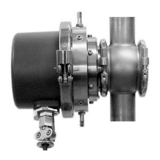
AquaScat 2 P — измеряется и учитывается проходящий и рассеянный свет (двухлучевая система), предназначен для измерения мутности в воде под давлением;
TurbiScat — измерение мутности проходит под углами 90 и 25°, имеется возможность дополнительного контроля цветности анализируемой жидкости;
AquaMaster — имеется возможность дополнительного определения рН и концентрации растворенного кислорода.
Общий вид анализаторов представлен на рисунках 1 — 4.
Схема пломбировки от несанкционированного доступа, обозначение места нанесения знака поверки представлены на рисунке 5.
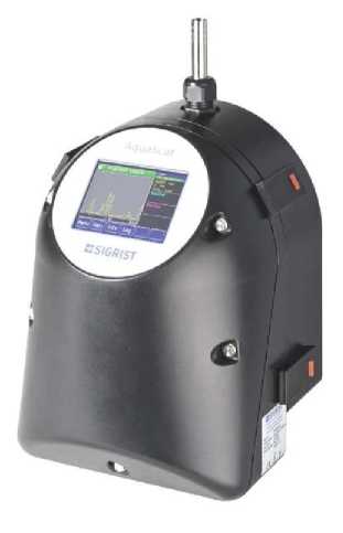
Рисунок 1 — Общий вид Анализаторов мутности моделей AquaScat 2 WTM/WTM-A и AquaScat 2 HT
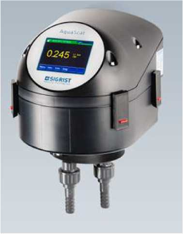
Рисунок 2 — Общий вид Анализатора мутности модели AquaScat 2 P
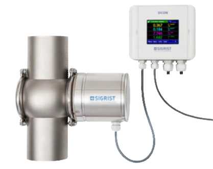
Рисунок 3 — Общий вид Анализатора мутности модели TurbiScat
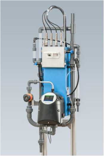
Рисунок 4 — Общий вид Анализатора мутности модели AquaMaster
Место нанесения
знака поверки
Место пломбировки
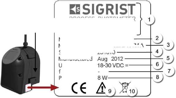
Рисунок 5 — Схема пломбировки, обозначение места нанесения знака поверки и маркировки:
1 — Производитель; 2 — Страна происхождения; 3 — название изделия; 4 — Серийный номер;
5 — Дата производства; 6 — Рабочее напряжение; 7 — Диапазон частот; 8 — Мощность;
9 — следуйте руководству по эксплуатации; 10 — следуйте информации по утилизации
PROCESS-PHOTOMETER
CH-6373 Ennetburgen www.photometer.com
Switzerland — AquaScat 2 WTM A 251010
Made in Model name Serial NO Manufactured