-
Contents
-
Table of Contents
-
Bookmarks
Quick Links
SINUMERIK
SINUMERIK 828D
PPU and components
Manual
Valid for:
SINUMERIK 828D
PPU 24x.3 BASIC / PPU 26x.3 / PPU 28x.3
CNC-Software V4.5 SP5
05/2015
6FC5397-2DP40-3BA4
Preface
Fundamental safety
instructions
System description
Application planning
Installing
Rules for permitted topologies
Interface description
Anschließbare Komponenten
Technical data
Spare parts and accessories
Appendix
1
2
3
4
5
6
7
8
9
A
Summary of Contents for Siemens Sinumerik 828D
![]()
SINUMERIK
SINUMERIK 828D
Turning and Milling
Commissioning Manual
Valid for:
NCU system software Version 2.6 HMI sl Version 2.6
09/2009
Preface
|
Scope of delivery and |
||
|
1 |
||
|
requirements |
||
|
Settings on the HMI |
2 |
|
|
Commissioning the PLC |
3 |
|
|
Commissioning the drive |
4 |
|
|
Setting NCK machine data |
5 |
|
|
Configuring cycles |
6 |
|
|
Service Planner |
7 |
|
|
Easy Extend |
8 |
|
|
Tool management |
9 |
|
|
Series start-up |
10 |
|
|
References |
A |
|
|
List of abbreviations |
B |
|
6FC5397-3DP20-0BA0

Legal information
Warning notice system
This manual contains notices you have to observe in order to ensure your personal safety, as well as to prevent damage to property. The notices referring to your personal safety are highlighted in the manual by a safety alert symbol, notices referring only to property damage have no safety alert symbol. These notices shown below are graded according to the degree of danger.
 DANGER
indicates that death or severe personal injury will result if proper precautions are not taken.
 WARNING
indicates that death or severe personal injury may result if proper precautions are not taken.
 CAUTION
with a safety alert symbol, indicates that minor personal injury can result if proper precautions are not taken.
CAUTION
without a safety alert symbol, indicates that property damage can result if proper precautions are not taken.
NOTICE
indicates that an unintended result or situation can occur if the corresponding information is not taken into account.
If more than one degree of danger is present, the warning notice representing the highest degree of danger will be used. A notice warning of injury to persons with a safety alert symbol may also include a warning relating to property damage.
Qualified Personnel
The product/system described in this documentation may be operated only by personnel qualified for the specific task in accordance with the relevant documentation for the specific task, in particular its warning notices and safety instructions. Qualified personnel are those who, based on their training and experience, are capable of identifying risks and avoiding potential hazards when working with these products/systems.
Proper use of Siemens products
Note the following:
 WARNING
Siemens products may only be used for the applications described in the catalog and in the relevant technical documentation. If products and components from other manufacturers are used, these must be recommended or approved by Siemens. Proper transport, storage, installation, assembly, commissioning, operation and maintenance are required to ensure that the products operate safely and without any problems. The permissible ambient conditions must be adhered to. The information in the relevant documentation must be observed.
Trademarks
All names identified by ® are registered trademarks of the Siemens AG. The remaining trademarks in this publication may be trademarks whose use by third parties for their own purposes could violate the rights of the owner.
Disclaimer of Liability
We have reviewed the contents of this publication to ensure consistency with the hardware and software described. Since variance cannot be precluded entirely, we cannot guarantee full consistency. However, the information in this publication is reviewed regularly and any necessary corrections are included in subsequent editions.
|
Siemens AG |
Order number: 6FC5397-3DP20-0BA0 |
Copyright © Siemens AG 2009. |
|
Industry Sector |
10/2009 |
Technical data subject to change |
|
Postfach 48 48 |
||
|
90026 NÜRNBERG |
||
|
GERMANY |
Preface
SINUMERIK documentation
The SINUMERIK documentation is organized in three parts:
●General documentation
●User documentation
●Manufacturer/service documentation
Information on the following topics is available at
http://www.siemens.com/motioncontrol/docu:
●Ordering documentation:
Here you can find an up-to-date overview of publications.
●Downloading documentation:
Links to more information for downloading files from Service & Support.
●Researching documentation online
Information on DOConCD and direct access to the publications in DOConWEB.
●Compiling individual documentation on the basis of Siemens contents with the My Documentation Manager (MDM), refer to http://www.siemens.com/mdm
My Documentation Manager provides you with a range of features for generating your own machine documentation.
●Training and FAQs
Information on our range of training courses and FAQs (frequently asked questions) is available via the page navigation.
Target group
This documentation is intended for commissioning personnel.
The plant or system is readily assembled and wired. For the following steps, e.g. configuring the individual components, the Commissioning Manual contains all necessary information or at least references.
Benefits
The intended target group can use the Commissioning Manual to test and commission the system or the plant correctly and safely.
Utilization phase: Setup and commissioning phase
|
Turning and Milling |
3 |
|
Commissioning Manual, 09/2009, 6FC5397-3DP20-0BA0 |

Preface
Standard version
This documentation only describes the functionality of the standard version. Extensions or changes made by the machine manufacturer are documented by the machine manufacturer.
Other functions not described in this documentation might be executable in the control. However, no claim can be made regarding the availability of these functions when the equipment is first supplied or in the event of servicing.
Further, for the sake of simplicity, this documentation does not contain all detailed information about all types of the product and cannot cover every conceivable case of installation, operation or maintenance.
Structure of the documentation:
|
Target group |
Manual |
|
User |
• SINUMERIK 828D/840D sl Operating Manual HMI sl Turning |
|
• SINUMERIK 828D/840D sl Operating Manual HMI sl Milling |
|
|
• SINUMERIK 828D/840D sl Programming Manual Fundamentals |
|
|
• SINUMERIK 828D/840D sl Programming Manual Job Planning |
|
|
• SINUMERIK 840D sl Programming Manual Measuring Cycles |
|
|
• SINUMERIK 802D sl/828D/840D sl |
|
|
Programming Manual, ISO Dialects Turning |
|
|
Programming Manual, ISO Dialects Milling |
|
|
• SINUMERIK 828D Diagnostics Manual |
|
|
Manufacturer |
• SINUMERIK 828D Manual PPU |
|
• SINUMERIK 828D Commissioning Manual Turning and Milling |
|
|
• SINUMERIK 828D Service Manual Hardware and Software |
|
|
• SINUMERIK 828D Parameter Manual |
|
|
• SINUMERIK 828D/840D sl Function Manual Basic Functions |
|
|
• SINUMERIK 828D/840D sl Function Manual Extended Functions |
|
|
• SINUMERIK 840D sl Function Manual Tool Management |
|
|
• SINUMERIK 802D sl/828D/840D sl Function Manual ISO Dialects |
|
|
• SIMATIC NET System Manual GPRS/GSM Modem SINAUT MD720-3 |
|
|
• SIMATIC NET Operating Instructions Quad-Band GSM Antenna |
|
|
SINAUT 794-4MR |
|
Additional references:
|
Subject |
Manual |
|
|
RCS Commander |
Online help |
|
|
Programming Tool PLC828 |
Online help |
|
|
Easy Screen |
SINUMERIK 840D sl Programming Manual Easy Screen |
|
|
in: Commissioning Manual Base Software and HMI sl |
||
|
Easy Message |
SINUMERIK 828D/840D sl Operating Manual HMI sl Turning |
|
|
SINUMERIK 828D/840D sl Operating Manual HMI sl Milling |
||
|
ePS Network Services |
ePS Network Services Function Manual and online help |
|
|
4 |
Turning and Milling |
|
|
Commissioning Manual, 09/2009, 6FC5397-3DP20-0BA0 |

Preface
|
Subject |
Manual |
|
Networking |
SINUMERIK 840D sl Manual |
|
Operator Components and Networking |
|
|
SAFETY (safe standstill) |
SINAMICS S120/SINUMERIK 840D sl Manual Machine |
|
Configuration |
Questions about this documentation
If you have any queries (suggestions, corrections) in relation to this documentation, please send a fax or e-mail to the following address:
|
Fax |
+49 9131 98 2176 |
|
|
mailto:docu.motioncontrol@siemens.com |
A fax form is available at the end of this document.
SINUMERIK Internet address
http://www.siemens.com/sinumerik
Technical Support
If you have any technical questions, please contact our hotline:
|
Europe/Africa |
||
|
Phone |
+49 180 5050 222 |
|
|
Fax |
+49 180 5050 223 |
0.14 €/min from the German fixed-line network; cell phone charges may vary.
|
Internet |
http://www.siemens.com/automation/support-request |
|
|
Americas |
||
|
Phone |
+1 423 262 2522 |
|
|
Fax |
+1 423 262 2200 |
|
|
|
mailto:techsupport.sea@siemens.com |
|
|
Asia/Pacific |
||
|
Phone |
+86 1064 757575 |
|
|
Fax |
+86 1064 747474 |
|
|
|
mailto:support.asia.automation@siemens.com |
|
Turning and Milling |
5 |
|
Commissioning Manual, 09/2009, 6FC5397-3DP20-0BA0 |

Preface
Note
National telephone numbers for technical support are provided under the following Internet address:
http://www.siemens.com/automation/partner
EC Declaration of Conformity
The EC Declaration of Conformity for the EMC Directive can be found on the Internet at: http://support.automation.siemens.com
under the Product Order No. 15257461, or at the relevant branch office of I DT MC Division of Siemens AG.
CompactFlash cards for users
●The SINUMERIK CNC supports the file systems FAT16 and FAT32 for CompactFlash cards. You may need to format the memory card if you want to use a memory card from another device or if you want to ensure the compatibility of the memory card with the SINUMERIK. However, formatting the memory card will permanently delete all data on it.
●Do not remove the memory card while it is being accessed. This can lead to damage of the memory card and the SINUMERIK as well as the data on the memory card.
●If you cannot use a memory card with the SINUMERIK, it is probably because the memory card is not formatted for the control system (e.g. Ext3 Linux file system), the memory card file system is faulty or it is the wrong type of memory card.
●Insert the memory card carefully with the correct orientation into the memory card slot (take note of arrows, etc.). This way you avoid mechanical damage to the memory card or the device.
●Only use memory cards that have been approved by Siemens for use with SINUMERIK. Even though the SINUMERIK keeps to the general industry standards for memory cards, it is possible that memory cards from some manufacturers will not function perfectly in this device or are not completely compatible with it (you can obtain information on compatibility from the memory card manufacturer or supplier).
●The CompactFlash card from SanDisk «CompactFlash® 5000 Industrial Grade» has been approved for SINUMERIK (Order Number 6FC5313-5AG00-0AA0).
|
6 |
Turning and Milling |
|
Commissioning Manual, 09/2009, 6FC5397-3DP20-0BA0 |
Table of contents
|
Preface…………………………………………………………………………………………………………………………………… |
3 |
||
|
1 |
Scope of delivery and requirements ………………………………………………………………………………………….. |
13 |
|
|
1.1 |
System overview………………………………………………………………………………………………………….. |
13 |
|
|
1.2 |
Toolbox CD and other available tools……………………………………………………………………………… |
14 |
|
|
1.3 |
This is the general sequence for commissioning………………………………………………………………. |
15 |
|
|
1.4 |
Starting up the control…………………………………………………………………………………………………… |
16 |
|
|
1.5 |
Communication with the control……………………………………………………………………………………… |
19 |
|
|
1.5.1 |
How to communicate with the control using the Programming Tool…………………………………….. |
19 |
|
|
1.5.2 |
Example: How to communicate with the control using the NCU Connection Wizard……………… |
23 |
|
|
1.5.3 |
How to communicate with the control using the RCS Commander……………………………………… |
25 |
|
|
1.5.4 |
Communicating with the control via X130………………………………………………………………………… |
28 |
|
|
2 |
Settings on the HMI………………………………………………………………………………………………………………… |
31 |
|
|
2.1 |
Access levels………………………………………………………………………………………………………………. |
31 |
|
|
2.2 |
How to set and change the password……………………………………………………………………………… |
33 |
|
|
2.3 |
Available system languages ………………………………………………………………………………………….. |
34 |
|
|
2.4 |
How to set the date and time…………………………………………………………………………………………. |
35 |
|
|
2.5 |
Checking and entering licenses……………………………………………………………………………………… |
36 |
|
|
2.5.1 |
How to enter a license key…………………………………………………………………………………………….. |
37 |
|
|
2.5.2 |
How to determine the license requirement………………………………………………………………………. |
38 |
|
|
2.6 |
Configuring user alarms………………………………………………………………………………………………… |
40 |
|
|
2.6.1 |
Structure of user PLC alarms…………………………………………………………………………………………. |
40 |
|
|
2.6.2 |
How to create user PLC alarms……………………………………………………………………………………… |
42 |
|
|
2.6.3 |
Configuring the alarm log………………………………………………………………………………………………. |
43 |
|
|
2.6.4 |
How to configure the log……………………………………………………………………………………………….. |
44 |
|
|
2.6.5 |
Configuring user alarms with colors………………………………………………………………………………… |
46 |
|
|
2.6.6 |
How to configure colors for user alarms………………………………………………………………………….. |
47 |
|
|
2.7 |
Creating OEM-specific online help …………………………………………………………………………………. |
50 |
|
|
2.7.1 |
Structure and syntax of the configuration file……………………………………………………………………. |
50 |
|
|
2.7.2 |
Structure and syntax of the help book…………………………………………………………………………….. |
52 |
|
|
2.7.3 |
Description of the syntax for the online help…………………………………………………………………….. |
53 |
|
|
2.7.4 |
Example: How to create an OEM-specific help ………………………………………………………………… |
57 |
|
|
2.7.5 |
Example: How to create an online help for user PLC alarms……………………………………………… |
60 |
|
|
3 |
Commissioning the PLC………………………………………………………………………………………………………….. |
63 |
|
|
3.1 |
Activating I/O modules………………………………………………………………………………………………….. |
64 |
|
|
4 |
Commissioning the drive …………………………………………………………………………………………………………. |
67 |
|
|
4.1 |
Configuring the drive…………………………………………………………………………………………………….. |
67 |
|
|
4.1.1 |
Example of a drive configuration…………………………………………………………………………………….. |
67 |
|
|
4.1.2 |
Example: How to configure the drive………………………………………………………………………………. |
69 |
|
|
4.1.3 |
Example: How to configure the infeed…………………………………………………………………………….. |
76 |
|
|
4.1.4 |
Example: How to configure the external encoder……………………………………………………………… |
78 |
|
|
Turning and Milling |
7 |
||
|
Commissioning Manual, 09/2009, 6FC5397-3DP20-0BA0 |

Table of contents
|
4.1.5 |
Example: How to assign the axes………………………………………………………………………………….. |
83 |
|
|
4.1.6 |
Example: Setting machine data for an axis/spindle………………………………………………………….. |
88 |
|
|
4.1.7 |
Parameters for the axis/spindle test run …………………………………………………………………………. |
89 |
|
|
4.2 |
Terminal assignments………………………………………………………………………………………………….. |
91 |
|
|
4.2.1 |
Terminal assignment on X122………………………………………………………………………………………. |
91 |
|
|
4.2.2 |
Terminal assignment on X132………………………………………………………………………………………. |
92 |
|
|
4.2.3 |
Terminal assignment on X122 for a Numeric Control Extension………………………………………… |
93 |
|
|
4.2.4 |
Example: Circuitry for a CU with line contactor………………………………………………………………… |
94 |
|
|
4.2.5 |
Connecting the probes…………………………………………………………………………………………………. |
97 |
|
|
5 |
Setting NCK machine data……………………………………………………………………………………………………… |
101 |
|
|
5.1 |
Classification of machine data…………………………………………………………………………………….. |
101 |
|
|
5.2 |
Processing part programs from external CNC systems…………………………………………………… |
104 |
|
|
6 |
Configuring cycles ………………………………………………………………………………………………………………… |
105 |
|
|
6.1 |
Settings for activating cycles……………………………………………………………………………………….. |
105 |
|
|
6.1.1 |
How to adapt the manufacturer cycles………………………………………………………………………….. |
109 |
|
|
6.1.2 |
Standard cycle PROG_EVENT.SPF…………………………………………………………………………….. |
110 |
|
|
6.1.3 |
Setting the simulation and simultaneous recording (option)…………………………………………….. |
111 |
|
|
6.2 |
Drilling ……………………………………………………………………………………………………………………… |
113 |
|
|
6.2.1 |
Technology cycles for drilling………………………………………………………………………………………. |
113 |
|
|
6.2.2 |
ShopTurn: Drilling centered ………………………………………………………………………………………… |
115 |
|
|
6.3 |
Milling………………………………………………………………………………………………………………………. |
116 |
|
|
6.3.1 |
Technology cycles for milling………………………………………………………………………………………. |
116 |
|
|
6.3.2 |
Cylinder surface transformation (TRACYL) …………………………………………………………………… |
117 |
|
|
6.3.3 |
Example: Axis configuration for milling machines…………………………………………………………… |
118 |
|
|
6.3.4 |
ShopMill: Setting up cycles for milling…………………………………………………………………………… |
121 |
|
|
6.4 |
Turning…………………………………………………………………………………………………………………….. |
124 |
|
|
6.4.1 |
Technology cycles for turning………………………………………………………………………………. |
…….. 124 |
|
|
6.4.2 |
Example: Residual material machining…………………………………………………………………………. |
127 |
|
|
6.4.3 |
Example: Axis configuration for lathes………………………………………………………………………….. |
129 |
|
|
6.4.4 |
Cylinder surface transformation (TRACYL) …………………………………………………………………… |
130 |
|
|
6.4.5 |
End face machining (TRANSMIT)………………………………………………………………………………… |
133 |
|
|
6.4.6 |
Inclined axis (TRAANG)……………………………………………………………………………………………… |
136 |
|
|
6.4.7 |
ShopTurn: Setting up cycles for turning………………………………………………………………………… |
139 |
|
|
6.4.8 |
ShopTurn: Counterspindle………………………………………………………………………………………….. |
146 |
|
|
6.4.9 |
ShopTurn: Cylinder surface transformation (TRACYL) …………………………………………………… |
150 |
|
|
6.4.10 |
ShopTurn: End face machining (TRANSMIT)………………………………………………………………… |
151 |
|
|
6.4.11 |
ShopTurn: Inclined axis (TRAANG)……………………………………………………………………………… |
152 |
|
|
6.5 |
Swivel………………………………………………………………………………………………………………………. |
153 |
|
|
6.5.1 |
Technology cycles for swiveling…………………………………………………………………………………… |
153 |
|
|
6.5.2 |
Setting the workpiece, tool and rotary table reference ……………………………………………………. |
156 |
|
|
6.5.3 |
ShopMill: Swivel plane and swivel tool …………………………………………………………………………. |
159 |
|
|
6.5.4 |
CYCLE800 checklist for the identification of the machine kinematics……………………………….. |
160 |
|
|
6.5.5 |
Commissioning of the kinematic chain (swivel data record)…………………………………………….. |
161 |
|
|
6.5.6 |
Example of the commissioning of swivel head 1……………………………………………………………. |
167 |
|
|
6.5.7 |
Example of the commissioning of swivel head 2……………………………………………………………. |
168 |
|
|
6.5.8 |
Example of the commissioning of a cardanic table…………………………………………………………. |
170 |
|
|
6.5.9 |
Example of the commissioning of a swivel head/rotary table…………………………………………… |
172 |
|
|
6.5.10 |
Example of the commissioning of a swivel table ……………………………………………………………. |
174 |
|
|
6.5.11 |
Manufacturer cycle CUST_800.SPF…………………………………………………………………………….. |
176 |
|
|
8 |
Turning and Milling |
||
|
Commissioning Manual, 09/2009, 6FC5397-3DP20-0BA0 |
|
Table of contents |
|||
|
6.6 |
High Speed Settings (Advanced Surface)……………………………………………………………………… |
182 |
|
|
6.6.1 |
Configuring the High Speed Settings function (CYCLE832) …………………………………………….. |
182 |
|
|
6.6.2 |
How to adapt the High Speed Settings function (CYCLE832)…………………………………………… |
184 |
|
|
6.7 |
Measuring cycles and measurement functions……………………………………………………………….. |
186 |
|
|
6.7.1 |
General settings for measuring…………………………………………………………………………………….. |
186 |
|
|
6.7.2 |
Manufacturer cycle CUST_MEACYC.SPF …………………………………………………………………….. |
189 |
|
|
6.7.3 |
Measuring in the JOG mode………………………………………………………………………………………… |
189 |
|
|
6.7.4 |
JOG: Measure workpiece during milling………………………………………………………………………… |
191 |
|
|
6.7.5 |
JOG: Measure tool during milling………………………………………………………………………………….. |
193 |
|
|
6.7.6 |
JOG: Measure tool during turning…………………………………………………………………………………. |
197 |
|
|
6.7.7 |
Measuring in the AUTOMATIC mode……………………………………………………………………………. |
198 |
|
|
6.7.8 |
AUTO: General settings for the workpiece measurement………………………………………………… |
200 |
|
|
6.7.9 |
AUTO: Measure workpiece during milling ……………………………………………………………………… |
202 |
|
|
6.7.10 |
AUTO: Measure workpiece during turning……………………………………………………………………… |
204 |
|
|
6.7.11 |
AUTO: Measure tool during milling……………………………………………………………………………….. |
205 |
|
|
6.7.12 |
AUTO: Measure tool during turning (CYCLE982)……………………………………………………………. |
213 |
|
|
7 |
Service Planner……………………………………………………………………………………………………………………. |
215 |
|
|
7.1 |
PLC user program………………………………………………………………………………………………………. |
217 |
|
|
7.2 |
Interfaces in the PLC user program………………………………………………………………………………. |
218 |
|
|
7.3 |
Functions on the HMI………………………………………………………………………………………………….. |
223 |
|
|
8 |
Easy Extend ………………………………………………………………………………………………………………………… |
231 |
|
|
8.1 |
Overview of functions………………………………………………………………………………………………….. |
231 |
|
|
8.2 |
Configuration in the PLC user program…………………………………………………………………………. |
233 |
|
|
8.3 |
Display on the user interface ……………………………………………………………………………………….. |
235 |
|
|
8.4 |
Creating language-dependent texts………………………………………………………………………………. |
236 |
|
|
8.5 |
Description of the script language…………………………………………………………………………………. |
237 |
|
|
8.5.1 |
Special characters and operators……………………………………………………………………………. |
……238 |
|
|
8.5.2 |
Structure of the XML script ………………………………………………………………………………………….. |
239 |
|
|
8.5.3 |
CONTROL_RESET…………………………………………………………………………………………………….. |
241 |
|
|
8.5.4 |
DATA………………………………………………………………………………………………………………………… |
241 |
|
|
8.5.5 |
DATA_ACCESS…………………………………………………………………………………………………………. |
241 |
|
|
8.5.6 |
DATA_LIST……………………………………………………………………………………………………………….. |
242 |
|
|
8.5.7 |
DRIVE_VERSION………………………………………………………………………………………………………. |
243 |
|
|
8.5.8 |
FILE………………………………………………………………………………………………………………………….. |
244 |
|
|
8.5.9 |
FUNCTION………………………………………………………………………………………………………………… |
245 |
|
|
8.5.10 |
FUNCTION_BODY …………………………………………………………………………………………………….. |
246 |
|
|
8.5.11 |
INCLUDE ………………………………………………………………………………………………………………….. |
248 |
|
|
8.5.12 |
LET…………………………………………………………………………………………………………………………… |
248 |
|
|
8.5.13 |
MSGBOX ………………………………………………………………………………………………………………….. |
250 |
|
|
8.5.14 |
OP……………………………………………………………………………………………………………………………. |
251 |
|
|
8.5.15 |
OPTION_MD……………………………………………………………………………………………………………… |
252 |
|
|
8.5.16 |
PASSWORD……………………………………………………………………………………………………………… |
253 |
|
|
8.5.17 |
PLC_INTERFACE………………………………………………………………………………………………………. |
253 |
|
|
8.5.18 |
POWER_OFF…………………………………………………………………………………………………………….. |
254 |
|
|
8.5.19 |
PRINT ………………………………………………………………………………………………………………………. |
254 |
|
|
8.5.20 |
WAITING…………………………………………………………………………………………………………………… |
255 |
|
|
8.5.21 |
?up…………………………………………………………………………………………………………………………… |
256 |
|
|
8.5.22 |
XML identifiers for the dialog ……………………………………………………………………………………….. |
256 |
|
|
8.5.23 |
BOX………………………………………………………………………………………………………………………….. |
258 |
|
|
8.5.24 |
CONTROL…………………………………………………………………………………………………………………. |
258 |
|
|
Turning and Milling |
9 |
||
|
Commissioning Manual, 09/2009, 6FC5397-3DP20-0BA0 |

Table of contents
|
8.5.25 |
IMG………………………………………………………………………………………………………………………….. |
260 |
|
|
8.5.26 |
PROPERTY ……………………………………………………………………………………………………………… |
261 |
|
|
8.5.27 |
REQUEST………………………………………………………………………………………………………………… |
262 |
|
|
8.5.28 |
SOFTKEY_OK, SOFTKEY_CANCEL…………………………………………………………………………… |
262 |
|
|
8.5.29 |
TEXT……………………………………………………………………………………………………………………….. |
263 |
|
|
8.5.30 |
UPDATE_CONTROLS……………………………………………………………………………………………….. |
263 |
|
|
8.5.31 |
Addressing the parameters…………………………………………………………………………………………. |
264 |
|
|
8.5.32 |
Addressing the drive objects……………………………………………………………………………………….. |
266 |
|
|
8.5.33 |
XML identifiers for statements……………………………………………………………………………………… |
268 |
|
|
8.6 |
String functions …………………………………………………………………………………………………………. |
271 |
|
|
8.6.1 |
string.cmp…………………………………………………………………………………………………………………. |
271 |
|
|
8.6.2 |
string.icmp………………………………………………………………………………………………………………… |
272 |
|
|
8.6.3 |
string.left…………………………………………………………………………………………………………………… |
273 |
|
|
8.6.4 |
string.right…………………………………………………………………………………………………………………. |
273 |
|
|
8.6.5 |
string.middle……………………………………………………………………………………………………………… |
274 |
|
|
8.6.6 |
string.length………………………………………………………………………………………………………………. |
275 |
|
|
8.6.7 |
string.replace…………………………………………………………………………………………………………….. |
275 |
|
|
8.6.8 |
string.remove ……………………………………………………………………………………………………………. |
276 |
|
|
8.6.9 |
string.delete………………………………………………………………………………………………………………. |
277 |
|
|
8.6.10 |
string.insert……………………………………………………………………………………………………………….. |
277 |
|
|
8.6.11 |
string.find………………………………………………………………………………………………………………….. |
278 |
|
|
8.6.12 |
string.reversefind……………………………………………………………………………………………………….. |
279 |
|
|
8.6.13 |
string.trimleft……………………………………………………………………………………………………………… |
280 |
|
|
8.6.14 |
string.trimright …………………………………………………………………………………………………………… |
280 |
|
|
8.7 |
Trigonometric functions………………………………………………………………………………………………. |
282 |
|
|
8.8 |
Examples………………………………………………………………………………………………………………….. |
284 |
|
|
8.8.1 |
Example with control elements……………………………………………………………………………………. |
284 |
|
|
8.8.2 |
Example with parameters to support the commissioning ………………………………………………… |
285 |
|
|
8.8.3 |
User example for a power unit………………………………………………………………………………. |
……. 288 |
|
|
9 |
Tool management…………………………………………………………………………………………………………………. |
291 |
|
|
9.1 |
Fundamentals …………………………………………………………………………………………………………… |
291 |
|
|
9.1.1 |
Structure of the tool management………………………………………………………………………………… |
292 |
|
|
9.1.2 |
Components of the tool management…………………………………………………………………………… |
293 |
|
|
9.1.3 |
Loading and unloading tools manually………………………………………………………………………….. |
296 |
|
|
9.2 |
PLC — NCK user interface……………………………………………………………………………………………. |
297 |
|
|
9.2.1 |
Relocating, unloading, loading tool, positioning magazine………………………………………………. |
298 |
|
|
9.2.2 |
Tool change ……………………………………………………………………………………………………………… |
304 |
|
|
9.2.3 |
Transfer-step and acknowledgment-step tables…………………………………………………………….. |
311 |
|
|
9.3 |
Machine data for the tool management ………………………………………………………………………… |
313 |
|
|
9.4 |
PLC Program Blocks………………………………………………………………………………………………….. |
320 |
|
|
9.4.1 |
Acknowledgment process…………………………………………………………………………………………… |
320 |
|
|
9.4.2 |
Types of acknowledgment………………………………………………………………………………………….. |
321 |
|
|
9.4.3 |
Acknowledgment states……………………………………………………………………………………………… |
322 |
|
|
9.4.4 |
Configuring step tables ………………………………………………………………………………………………. |
327 |
|
|
9.4.5 |
Configuring acknowledgment steps……………………………………………………………………………… |
330 |
|
|
9.4.6 |
Adjust the PLC user program………………………………………………………………………………………. |
331 |
|
|
9.4.7 |
Information on magazine location………………………………………………………………………………… |
332 |
|
|
9.4.8 |
PI service: TMMVTL…………………………………………………………………………………………………… |
335 |
|
|
9.5 |
Example: Loading/unloading……………………………………………………………………………………….. |
336 |
|
|
9.6 |
Example: Change manual tools…………………………………………………………………………………… |
338 |
|
|
10 |
Turning and Milling |
||
|
Commissioning Manual, 09/2009, 6FC5397-3DP20-0BA0 |
|
Table of contents |
|||
|
9.7 |
Application example for turning machine ……………………………………………………………………….. |
342 |
|
|
9.7.1 |
Example: Turning machine with revolver magazine (MAG _ CONF _ MPF) …………………………… |
342 |
|
|
9.7.2 |
Example: Acknowledgment steps (turning machine) ……………………………………………………….. |
347 |
|
|
9.7.3 |
Example: Tool change cycle for turning machine ……………………………………………………………. |
348 |
|
|
9.7.4 |
Example: Tool change cycle for TCA command ……………………………………………………………… |
350 |
|
|
9.7.5 |
Example: Turning machine with counterspindle ……………………………………………………………… |
351 |
|
|
9.7.6 |
Example: Test for empty buffer …………………………………………………………………………………….. |
351 |
|
|
9.7.7 |
Example: Transporting a tool from a buffer into the magazine ………………………………………….. |
352 |
|
|
9.7.8 |
Example: Repeat «Prepare tool change» order ……………………………………………………………….. |
352 |
|
|
9.8 |
Application example for milling machine ………………………………………………………………………… |
354 |
|
|
9.8.1 |
Example: Milling machine with chain magazine and dual gripper (MAG _ CONF _ MPF) ………… |
354 |
|
|
9.8.2 |
Flow chart: Tool change ………………………………………………………………………………………………. |
360 |
|
|
9.8.3 |
Example: Acknowledgment steps (milling machine) ………………………………………………………… |
369 |
|
|
9.8.4 |
Example: Tool change cycle for milling machine …………………………………………………………….. |
371 |
|
|
10 |
Series start-up……………………………………………………………………………………………………………………… |
373 |
|
|
10.1 |
Series start — up and archiving ……………………………………………………………………………………….. |
374 |
|
|
10.2 |
How to create and read in a series start — up archive ………………………………………………………… |
376 |
|
|
10.3 |
Example: Data archiving «Easy Archive» (use case) ……………………………………………………….. |
378 |
|
|
10.4 |
Parameterizing the V.24 interface …………………………………………………………………………………. |
380 |
|
|
A |
References………………………………………………………………………………………………………………………….. |
383 |
|
|
A.1 |
List of language codes used for file names ……………………………………………………………………. |
383 |
|
|
A.2 |
List of the alarm number ranges …………………………………………………………………………………… |
384 |
|
|
A.3 |
List of the color codes …………………………………………………………………………………………………. |
385 |
|
|
A.4 |
Directory structure on the CompactFlash card ……………………………………………………………….. |
386 |
|
|
A.4.1 |
How to edit files in the file system …………………………………………………………………………………. |
389 |
|
|
A.5 |
Definitions for license management ………………………………………………………………………………. |
391 |
|
|
A.6 |
Rules for wiring with DRIVE — CLiQ ………………………………………………………………………………… |
393 |
|
|
B |
List of abbreviations………………………………………………………………………………………………………………. |
397 |
|
|
B.1 |
Abbreviations …………………………………………………………………………………………………………….. |
397 |
|
|
B.2 |
Feedback on the documentation …………………………………………………………………………………… |
400 |
|
|
B.3 |
Overview of documentation …………………………………………………………………………………………. |
402 |
|
|
Glossary |
……………………………………………………………………………………………………………………………… |
403 |
|
|
Index…………………………………………………………………………………………………………………………………… |
409 |
|
Turning and Milling |
11 |
|
Commissioning Manual, 09/2009, 6FC5397-3DP20-0BA0 |

Table of contents
|
12 |
Turning and Milling |
|
Commissioning Manual, 09/2009, 6FC5397-3DP20-0BA0 |

Scope of delivery and requirements |
1 |
1.1System overview
System design
The following configuration shows a typical example:
|
&RPSDQ QHWZRUN ,QGXVWULDO (WKHUQHW |
|
|
6,180(5,. ‘ |
|
|
3HHU WR SHHU |
|
|
6,1$87 0′ |
|
|
3* 3& |
|
‘5,9( &/L4 |
||||||||||||||
|
3/& , 2 LQWHUIDFH EDVHG |
||||||||||||||
|
[ KDQGZKHHOV |
RQ 352),1(7 |
|||||||||||||
|
6,1$0,&6 6 |
||||||||||||||
0&3 31
60&
|
6/0 |
600 |
600 |
600 |
600 |
||||||||
33 ‘ 31
6QFKURQRXV  PRWRU
PRWRU
|
6QFKURQRXV |
||||||
|
33 ‘ $ 31 |
||||||
|
PRWRU |
||||||
|
,QGXFWLRQ PRWRU |
||||||
6QFKURQRXV PRWRU
Figure 1-1 Configuration example
Turning and Milling
|
Commissioning Manual, 09/2009, 6FC5397-3DP20-0BA0 |
13 |

Scope of delivery and requirements 1.2 Toolbox CD and other available tools
1.2Toolbox CD and other available tools
Toolbox CD
The Toolbox CD for SINUMERIK 828D has the following content:
●PLC Programming Tool for Integrated PLC
●Commissioning software for SINAMICS S120
●PLC Library (example)
PLC Programming Tool for Integrated PLC
The following tool is available for programming the PLC: PLC Programming Tool for Integrated PLC. For the rest of this manual, this will be referred to using the abbreviation «Programming Tool».
Commissioning software for SINAMICS S120
Until the SINAMICS S120 commissioning functionality is completely available via the user interface, drive configuration and optimization is performed using the commissioning software for SINAMICS S120. The PC is connected using the Ethernet interface on the front of the SINUMERIK 828D.
Note
Ordering data
You can find the ordering data for the following tools in Catalog NC 61.
RCS Commander
The RCS Commander (Remote Control System) is a tool the commissioner can use to exchange files between the PC and the control very easily, using drag and drop.
For data transmission, the PC is connected directly to the Ethernet interface on the front of the control. For a point-to-point connection, time-consuming parameterization of the Ethernet interface is not necessary. All settings are made automatically by the RCS Commander. The RCS Commander can also access several NCUs sequentially via a company network.
STARTER drive/commissioning software
Drive commissioning for the SINUMERIK 828D can be performed using the STARTER drive commissioning software. Simple commissioning procedures which are usually performed by field service staff (such as activating direct measuring systems) can be executed directly via the SINUMERIK 828D user interface. Advanced commissioning procedures which are usually performed when the machine is being manufactured (such as drive optimization) can be executed offline via the commissioning software used for SINAMICS S120.
|
14 |
Turning and Milling |
|
Commissioning Manual, 09/2009, 6FC5397-3DP20-0BA0 |

Scope of delivery and requirements 1.3 This is the general sequence for commissioning
1.3This is the general sequence for commissioning
Requirements
The mechanical and electrical installation of the system must be completed.
●Check the system visually for:
–Correct mechanical installation with secure electrical connections
–Connection of the power supply
–Connection of shielding and grounding
●Switching on the control and startup in «Normal startup»:
Startup of the control is finished when the main screen is shown on the HMI.
Sequence overview
Commissioning of the SINUMERIK 828D is carried out in the following steps:
1.Install the software from Toolbox CD onto PG/PC See chapter «Scope of delivery and requirements»
2.Create communication connection with the control See chapter «Communication with the control»
3.Addressing the I/O
See chapter «Addressing the I/O modules»
4.Set HMI
See chapter «Settings on the HMI»
5.PLC functions
See Function Manual Basic Functions (P4)
6.Commission drive and connect probes See chapter «Configuring drive»
7.Setting NCK machine data
See chapter «Setting NCK machine data»
8.Configuring cycles
See chapter «Configuring cycles»
9.Define maintenance tasks and maintenance intervals See chapter «Service Planner»
10.Extend machine with additional devices See chapter «Easy Extend»
11.Tool management
See chapter «Tool management»
|
Turning and Milling |
15 |
|
Commissioning Manual, 09/2009, 6FC5397-3DP20-0BA0 |
Scope of delivery and requirements 1.4 Starting up the control
1.4Starting up the control
Control startup
Procedure:
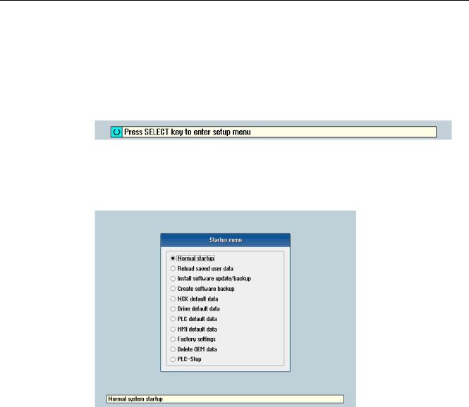
1.Switch the control on. The following display then appears during startup:
2.Press the <SELECT> key within three seconds.
3.Then press the following keys in succession:
Menu reset key, HSK2 (horizontal SK2), VSK2 (vertical SK2)
4.The «Setup menu» is displayed, «Normal startup» is the default setting.
Operating modes for startup
|
Selection |
Function |
|
|
Normal startup |
The system carries out a normal startup. |
|
|
Reload saved user data |
The system loads the stored user data («Save data» softkey) |
|
|
from the system CompactFlash card. |
||
|
Install software update/backup |
An update is installed on the system CompactFlash card from |
|
|
the user CompactFlash card or USB FlashDrive. |
||
|
Create software backup |
A backup of the system CompactFlash card is saved to the user |
|
|
CompactFlash card or USB FlashDrive. |
||
|
NCK default data |
The system loads the Siemens NCK data default settings and |
|
|
deletes the retentive data on the PLC. |
||
|
Drive default data |
The SINAMICS user data is deleted. |
|
|
PLC default data |
PLC general reset and load default NOP PLC program. |
|
|
16 |
Turning and Milling |
|
|
Commissioning Manual, 09/2009, 6FC5397-3DP20-0BA0 |

|
Scope of delivery and requirements |
|||
|
1.4 Starting up the control |
|||
|
Selection |
Function |
||
|
HMI default data |
The HMI user data is deleted. |
||
|
Factory settings |
Choice between two cases: No [case 1]/ Yes [case 2] |
||
|
• |
Case 1: |
||
|
The SINAMICS user data is deleted. |
|||
|
Siemens standard NCK data is loaded. |
|||
|
PLC general reset and load default NOP PLC program. |
|||
|
Save HMI user data. |
|||
|
• |
Case 2: |
||
|
As case 1 and additionally: |
|||
|
Deletion of the data in the /oem and /addon directories. |
|||
|
Delete OEM data |
All the data under /oem and /addon is deleted: OEM archives; |
||
|
OEM alarm texts; Easy Screen application. |
|||
|
PLC stop |
PLC is stopped. |
NOTICE
Replacement of the system CompactFlash card between different PPUs
Because of the system-related dependency between the CompactFlash card and SRAM for the data storage in the SINUMERIK 828D, the system CompactFlash card should be considered as a permanently installed EEPROM and should not be replaced!
If this has to be performed for imperative reasons, the replacement of the system CompactFlash card is detected during startup because of the stored serial number.
The reaction of the control is the loading of saved during startup (backup was performed previously with «Save data» softkey). If no stored data is found, a startup is performed automatically with the «NCK default data».
|
Turning and Milling |
17 |
|
Commissioning Manual, 09/2009, 6FC5397-3DP20-0BA0 |
Scope of delivery and requirements 1.4 Starting up the control
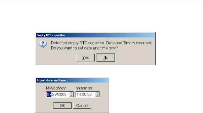
Empty RTC capacitor
If the RTC capacitor is discharged, the following message is issued during startup:
You can then reset the date and time:
The capacitor is then charged again when the control is switched on during startup.
|
18 |
Turning and Milling |
|
Commissioning Manual, 09/2009, 6FC5397-3DP20-0BA0 |

Scope of delivery and requirements 1.5 Communication with the control
1.5Communication with the control
Creating the connection
An Ethernet cable is needed to connect the control and PG/PC. The following Ethernet interfaces are available on the control:
●Connection via X127 (behind the flap on the front): Cable type: Crossed Ethernet cable
At interface X127, the control is preset as a DHCP server, delivering the IP address192.168.215.1 for a direct connection (peer-to-peer connection).
●Connection via X130 (at the back): Cable type: Uncrossed Ethernet cable
The interface X130 is the connection to the company network. The IP address that the PG/PC receives here as a DHCP client is determined by the DHCP server from the company network or fixed IP address is entered manually.
1.5.1How to communicate with the control using the Programming Tool
Setting up the communications interface in the Programming Tool
Proceed as follows to set up the network connection in the Programming Tool:
1.Start the Programming Tool.
2.In the navigation bar, click the «Communication» icon or select «View» → «Communication» from the menu.
3.In the left column, under «Communications parameters» enter 192.168.215.1as the IP address for X127.
4.Double click on the icon «TCP/IP» at the top right.
|
Turning and Milling |
19 |
|
Commissioning Manual, 09/2009, 6FC5397-3DP20-0BA0 |

Scope of delivery and requirements
1.5Communication with the control
5.In the dialog «PG/PC interface» select the TCP/IP protocol of the PG/PC. Normally this is the network card of the PC.
Figure 1-2 TCP/IP communications settings
6. Confirm with «OK».
|
20 |
Turning and Milling |
|
Commissioning Manual, 09/2009, 6FC5397-3DP20-0BA0 |
![]()
Scope of delivery and requirements 1.5 Communication with the control
7.Connect by double clicking on the icon «Double click to update». If the connection is made successfully, the icon will be displayed with a green border:
Figure 1-3 Online connection
8.If the connection is unsuccessful, the following setting may have to be deactivated:
Select «Control Panel» → «Network Connections»→ «Local Area Connection» «Properties»→ «Advanced»→ «Windows Firewall» → «Settings»→ «Advanced»: Deactivate the option «Local Area Connection».
|
Turning and Milling |
21 |
|
Commissioning Manual, 09/2009, 6FC5397-3DP20-0BA0 |

Scope of delivery and requirements 1.5 Communication with the control
Figure 1-4 Deactivate option
Confirm with «OK» and repeat Step 7.
|
22 |
Turning and Milling |
|
Commissioning Manual, 09/2009, 6FC5397-3DP20-0BA0 |
Scope of delivery and requirements 1.5 Communication with the control
1.5.2Example: How to communicate with the control using the NCU Connection Wizard
Requirements
The commissioning software for SINAMICS S120 is installed on the PG/PC. The «NCU Connection Wizard» is part of this software.
The connection to the control has already been set up via the Programming Tool.
Create connection to control
Procedure for the PG/PC:
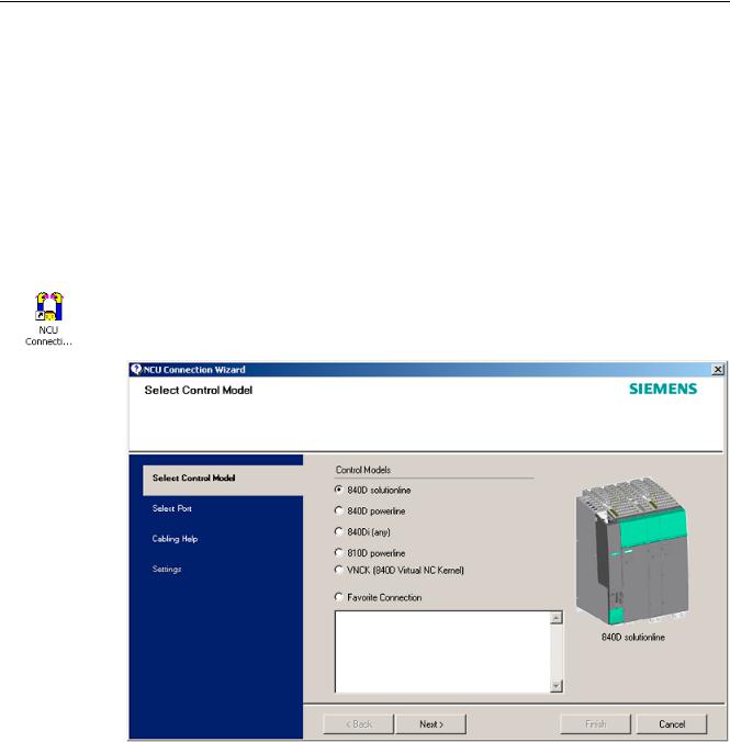
1.Start the «NCU Connection Wizard» via this link or via the Start menu.
2.In the «Select Control Model» dialog, select «840D solution line» for the NCU type connection to the SINUMERIK 828D.
Figure 1-5 Select the NCU type
|
Turning and Milling |
23 |
|
Commissioning Manual, 09/2009, 6FC5397-3DP20-0BA0 |
Scope of delivery and requirements
1.5Communication with the control
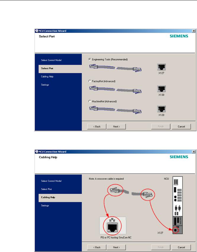
3.In the «Select Port» dialog, select the connection to the control that you have connected via Ethernet.
Figure 1-6 Select connection
4. Confirm the cable connection for both devices in the»Cabling Help» dialog.
|
Figure 1-7 |
Cabling |
|
24 |
Turning and Milling |
|
Commissioning Manual, 09/2009, 6FC5397-3DP20-0BA0 |
Scope of delivery and requirements 1.5 Communication with the control
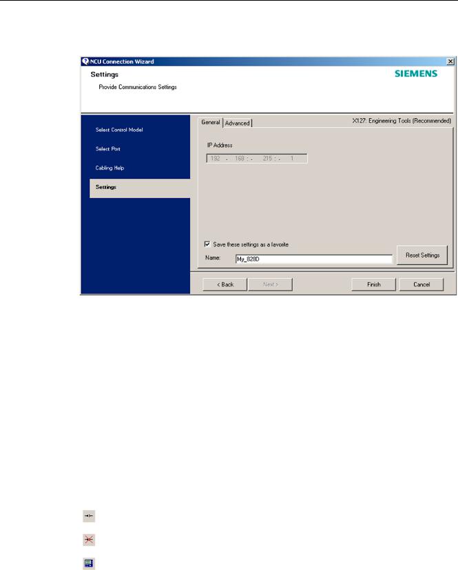
5. Check the IP address and enter the name for these settings in the «Settings» dialog.
Figure 1-8 Network settings
1.5.3How to communicate with the control using the RCS Commander
Connection options
The following options are available for the «RCS Commander» to create a connection with the control:
●Direct connection (peer-to-peer)
●Network connection
The current status of the connection is shown at the bottom in the RCS Commander status bar.
Meaning of the buttons:
Connect
Disconnect
Remote control
|
Turning and Milling |
25 |
|
Commissioning Manual, 09/2009, 6FC5397-3DP20-0BA0 |
Scope of delivery and requirements 1.5 Communication with the control
NOTICE
Generally only one connection is permitted, i.e. several simultaneous connections to different controls are not supported: So data exchange between two NCUs using «RCS Commander» is not possible.
Direct connection
To create a direct connection:
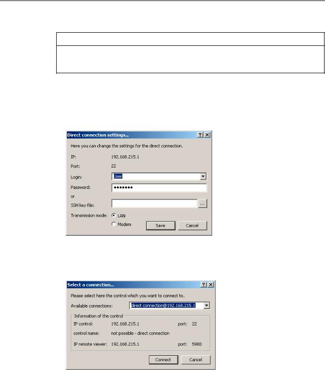
1. The login data is entered in the dialog «Settings» → «Connection» → «Direct connection»:
Figure 1-9 Dialog: Login data for direct connection
2.In the menu, select «Connection» → «Connect» → «Direct connection» or click the «Connect» button.
The following dialog box is displayed:
Figure 1-10 Dialog: Direct connection
3.The last selected direct connection is highlighted. Using the «Connect» button, a connection to the IP address196.168.215.1 is created.
This dialog does not appear when the direct connection is selected using the menu.
|
26 |
Turning and Milling |
|
Commissioning Manual, 09/2009, 6FC5397-3DP20-0BA0 |
Scope of delivery and requirements 1.5 Communication with the control
Network connection
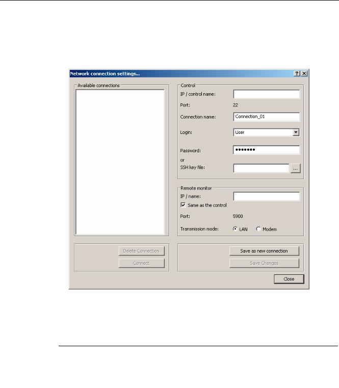
To create a network connection:
1.In the menu, select «Settings» → «Connection» → «Direct connection» or click the «Connect» button.
Figure 1-11 Dialog: Network connection
2.In the menu, select «Connection» → «Connect» → «Network connection» or select – if available – one of the previously selected connections.
3.Connection is made to the parameterized control.
Note
SSh key file
As an alternative to entering a password, the user may also use an SSh key for authentication. Please refer to the Online Help for more information on this topic.
|
Turning and Milling |
27 |
|
Commissioning Manual, 09/2009, 6FC5397-3DP20-0BA0 |
Scope of delivery and requirements 1.5 Communication with the control
1.5.4Communicating with the control via X130
Connection to the company network
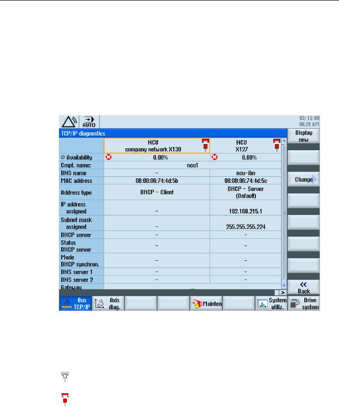
The NCU is connected to the company network via the Ethernet interface X130. The company network is used, for example, to access the network drives.
In the «Diagnostics» operating area select the «Bus TCP/IP » → «TCP/IP Diagnostics» → «Details» softkey with the menu forward key in order to set the parameters for the communication via X130.
Figure 1-12 Network settings
Connection properties
Company network X130
|
white |
Network cable inserted |
|
red |
Network cable not inserted |
|
28 |
Turning and Milling |
|
Commissioning Manual, 09/2009, 6FC5397-3DP20-0BA0 |

Scope of delivery and requirements 1.5 Communication with the control
Availability
The availability describes the percentage of faulty data compared to the entire data volume. Problems in the company network (e.g. logical drives that cannot be reached, double IP address, etc.) as well as settling time during power up can result in fluctuations in availability:
|
green |
Greater than 95% |
|
yellow |
50 — 95 % |
|
red |
Less than 50% |
Note
All information that is not available is marked in the relevant table line with a hyphen «-«.
|
Turning and Milling |
29 |
|
Commissioning Manual, 09/2009, 6FC5397-3DP20-0BA0 |

Scope of delivery and requirements 1.5 Communication with the control
|
30 |
Turning and Milling |
|
Commissioning Manual, 09/2009, 6FC5397-3DP20-0BA0 |
![]()
Settings on the HMI |
2 |
2.1Access levels
Access to functions and machine data
The user only has access to information corresponding to a particular access level and the levels below it. The machine data is assigned different access levels.
The access concept controls access to functions and data areas. Access levels 0 to 7 are available, where 0 represents the highest level and 7 the lowest level. Access levels 0 to 3 are locked using a password and 4 to 7 using the appropriate key-operated switch settings.
|
Access level |
Locked by |
Area |
Data class |
|
0 |
— |
System (reserved) |
System (S) |
|
1 |
Password: SUNRISE |
Manufacturer |
Manufacturer (M) |
|
2 |
Password: EVENING |
Servicing |
Individual (I) |
|
3 |
Password: CUSTOMER |
User |
User (U) |
|
4 |
Key-operated switch setting 3 |
Programmer, machine setter |
User (U) |
|
5 |
Key-operated switch setting 2 |
Qualified operator |
User (U) |
|
6 |
Key-operated switch setting 1 |
Trained operator |
User (U) |
|
7 |
Key-operated switch setting 0 |
Semi-skilled operator |
User (U) |
The password remains valid until it is reset with the «Delete Password» softkey. The passwords can be changed after activation.
If, for example, the passwords are no longer known, reinitialization (power up with
«NCK default data») must be carried out. This resets all passwords to the default (see table). POWER ON does not reset the password.
Note
PI LOGOUT
The password can also be deleted via the PLC.
|
Turning and Milling |
31 |
|
Commissioning Manual, 09/2009, 6FC5397-3DP20-0BA0 |

Settings on the HMI 2.1 Access levels
Key-operated switch
Access levels 4 to 7 require a corresponding key-operated switch setting on the machine control panel. Three keys of different colors are provided for this purpose. Each of these keys provides access only to certain areas.
Meaning of the key-operated switch settings:
|
Access level |
Switch setting |
Key color |
|
4-7 |
0 to 3 |
red |
|
5-7 |
0 to 2 |
green |
|
6-7 |
0 and 1 |
black |
|
7 |
0 = Key removal position |
No key inserted |
The key-operated switch setting must always be edited from the PLC user program and applied to the interface accordingly.
|
32 |
Turning and Milling |
|
Commissioning Manual, 09/2009, 6FC5397-3DP20-0BA0 |

Settings on the HMI 2.2 How to set and change the password
2.2How to set and change the password
Set password
To change the access level, select the «Start-up» operating area:
1.Press the «Password» softkey.
2.Press the «Set password» softkey to open the following dialog:
3.Enter a password and confirm this with «OK» or with the <Input> key.
A valid password is acknowledged as set and the currently applicable access level is displayed. Invalid passwords will be rejected.
4.You must delete the old password before activating a password for a lower access level than the one activated.
The last valid password is deleted by pressing the «Delete password» softkey. Then the current key-operated switch setting is valid.
Change password
To change the password:
1. Press the «Change password» softkey to open the following dialog:
Figure 2-2 Change password
2.Enter the new password in both fields and then confirm with the «OK» softkey. If both passwords match, the new password becomes valid and is adopted by the system.
|
Turning and Milling |
33 |
|
Commissioning Manual, 09/2009, 6FC5397-3DP20-0BA0 |

Settings on the HMI
2.3 Available system languages
2.3Available system languages
System languages
In the basic configuration, the SINUMERIK 828D is delivered with the following system languages:
●German
●English
●French
●Italian
●Spanish
●Portuguese (Brazil)
●Chinese (simplified)
●Chinese (traditional)
●Korean
All system languages are installed in the SINUMERIK 828D as delivered, so that a change of language can be carried out directly via the user interface, without having to download system language data.
Note
Additional languages
No CNC option needs to be ordered for the installation of additional languages not included in the scope of delivery.
The language files can be ordered on the DVD Additional Languages for SINUMERIK.
|
34 |
Turning and Milling |
|
Commissioning Manual, 09/2009, 6FC5397-3DP20-0BA0 |

Settings on the HMI 2.4 How to set the date and time
2.4How to set the date and time
Requirement
Changes can only be made with the appropriate access authorization (as of «User» and higher).
Setting the date and time
Procedure:
1.Select the «Start-up» operating area.
2.Press the «HMI» softkey.
3.Press the «Date/Time» softkey. The «Date/Time» window opens.
4.Select the required formats for the date and time in the «Format» field.
5.Confirm the entry with the «OK» softkey.
The new date and time details are accepted and output on the first line in the «current» fields.
|
Turning and Milling |
35 |
|
Commissioning Manual, 09/2009, 6FC5397-3DP20-0BA0 |

Settings on the HMI
2.5 Checking and entering licenses
2.5Checking and entering licenses
Use
The use of the installed system software and the options activated on a SINUMERIK control system require that the licenses purchased for this purpose are assigned to the hardware. In the course of this assignment, a license key is generated from the license numbers of the system software, the options, as well as the hardware serial number. Here, a license database administered by Siemens is accessed via the Internet. Finally, the license information including the license key is transferred to the hardware.
The license database can be accessed using the Web License Manager.
Web License Manager
By using the Web License Manager, you can assign licenses to hardware in a standard Web browser. To conclude the assignment, the license key must be entered manually on the control via the user interface.
The Internet address of the Web License Manager is: http://www.siemens.com/automation/license
Note
SINUMERIK software products
If a license key has not been activated or does not exist for a SINUMERIK software product, alarm 8080 is output by the control.
See also
Definitions for license management (Page 391)
|
36 |
Turning and Milling |
|
Commissioning Manual, 09/2009, 6FC5397-3DP20-0BA0 |

Settings on the HMI 2.5 Checking and entering licenses
2.5.1How to enter a license key
Requirement
The appropriate licenses are required for the activated options. After licensing the options in the Web License Manager, you receive a «license key» containing all options requiring a license and which is only valid for your system CompactFlash card.
To set or reset options, «Manufacturer» access rights are required.
Entering the license key
Procedure:
1.Select the «Start-up» operating area.
2.Press the menu forward key.
3.Press the «Licenses» softkey.
The «Licensing» window opens and gives you the following options:
–Determine the license requirement («All options» and «Missing licenses» softkeys)
–Softkey: «Exp. license requirement»
–Entry line: «Enter license key»
Figure 2-3 Entering the license key
|
Turning and Milling |
37 |
|
Commissioning Manual, 09/2009, 6FC5397-3DP20-0BA0 |

Settings on the HMI
2.5 Checking and entering licenses
2.5.2How to determine the license requirement
Determining the license requirement
Procedure:
1.Press the «All options» softkey to list all the options that can be selected for this control.
2.Activate or deactivate the required options in the «Set» column:
–Mark the checkbox
–Enter the number of options
Options displayed in red are activated, however are not licensed or insufficiently licensed.
— OR —
3.Press the «Missing licenses» softkey to display all options that are activated but not licensed. In the «Set» column, you can deselect the options that you do not require.
Figure 2-4 Licensing (example)
|
38 |
Turning and Milling |
|
Commissioning Manual, 09/2009, 6FC5397-3DP20-0BA0 |

Settings on the HMI 2.5 Checking and entering licenses
4.To activate new selected options, press the «Reset (po)» softkey. A safety prompt appears.
With HMI options, you will need to restart the HMI. Corresponding prompts will appear in the dialog line.
5.Press the «OK» softkey to trigger a warm restart. — OR —
6.Press the «Cancel» softkey to cancel the process.
|
Turning and Milling |
39 |
|
Commissioning Manual, 09/2009, 6FC5397-3DP20-0BA0 |

Settings on the HMI
2.6 Configuring user alarms
2.6Configuring user alarms
Creating user PLC alarms
The PLC alarms in the area from 700 000 — 700 247 are configured by the machine manufacturer. The access level «Manufacturer» is required with the appropriate password.
To enter the user PLC alarms via the user interface, select → «HMI»→ «Alarm texts» in the «Start-up» operating area.
Then you receive the following selection:
|
Alarm texts for |
Name of the xml file |
|
User cycle alarms |
oem_alarms_cycles |
|
User PLC alarms |
oem_alarms_plc |
|
User part program message texts |
oem_partprogram_messages |
Loading user PLC alarms
The alarm text files are only loaded during startup.
●«Alarm» attribute: red, is shown in the «alarm list».
●«Message» attribute: black, is shown under «Messages».
Select <MENU SELECT>, then the menu forward key and press the «HMI restart» softkey to load the alarm texts.
See also
You can find a detailed description of the alarms with system responses and deleting criteria in: SINUMERIK 828D Diagnostics Manual
2.6.1Structure of user PLC alarms
Structure of a user PLC alarm
The user PLC alarms have the following structure:
2LO SUHVVXUH WRR ORZ
|
$ODUP QXPEHU |
9DULDEOH |
$ODUP WH[W |
|
Figure 2-5 |
Alarm structure |
|
|
40 |
Turning and Milling |
|
|
Commissioning Manual, 09/2009, 6FC5397-3DP20-0BA0 |
![]()
Settings on the HMI 2.6 Configuring user alarms
The table below shows the mode of operation of the PLC alarms:
1.The alarm is triggered with the appropriate number and output via the PLC signal.
2.If a variable has been configured to this alarm, the value of this variable is in the specified data word of the PLC variable.
3.The NCK response when the alarm is triggered is defined in the MD14516[x] index (see table below).
4.The alarm text can be freely selected and may be up to 255 characters long.
|
Alarm number |
PLC signal |
PLC variable |
Alarm response |
Alarm text |
|
(MD) |
||||
|
700 000 |
DB1600.DBX0.0 |
DB1600.DBW1000 |
14516[0] |
Alarm 1 |
|
700 001 |
DB1600.DBX0.1 |
DB1600.DBW1004 |
14516[1] |
Alarm 2 |
|
700 002 |
DB1600.DBX0.2 |
DB1600.DBW1008 |
14516[2] |
Alarm 3 |
|
700 003 |
DB1600.DBX0.3 |
DB1600.DBW1012 |
14516[3] |
Alarm 4 |
|
700 004 |
DB1600.DBX0.4 |
DB1600.DBW1016 |
14516[4] |
Alarm 5 |
|
700 005 |
DB1600.DBX0.5 |
DB1600.DBW1020 |
14516[5] |
Alarm 6 |
|
700 006 |
DB1600.DBX0.6 |
DB1600.DBW1024 |
14516[6] |
Alarm 7 |
|
Continuation: |
||||
|
700 247 |
DB1600.DBX30.7 |
DB1600.DBW1988 |
14516[247] |
Alarm 248 |
Defining the NCK response
The following NCK responses are possible:
|
MD14516[x] |
Meaning |
|
Bit 0 |
NC start disabled |
|
Bit 1 |
Read-in disable |
|
Bit 2 |
Feed hold for all axes |
|
Bit 3 |
EMERGENCY STOP |
|
Bit 4 |
PLC in stop |
|
Bit 5 |
Reserved |
|
Bit 6 |
Definition for alarm or message |
|
Bit 6=1: → alarm, Bit 6=0: → message |
|
|
Bit 7 |
POWER ON |
|
Turning and Milling |
41 |
|
Commissioning Manual, 09/2009, 6FC5397-3DP20-0BA0 |

Settings on the HMI
2.6 Configuring user alarms
Configuring alarm texts with variables
The following data types are permitted for variables in the alarm text:
|
Variable |
Meaning |
|
%b |
Binary representation of a 32-bit value |
|
%d |
Integer decimal number |
|
%f |
4 byte floating point number |
|
%i |
Integer decimal number with sign |
|
%o |
Integer octal number |
|
%u |
Unsigned decimal number |
|
%x |
Integer hexadecimal number |
2.6.2How to create user PLC alarms
Notes for processing
The following points should be observed when processing the files:
●The files should be edited externally on a PG/PC with a text editor (e.g. notepad) or with an XML editor. The structure must not be altered.
●The created alarm text files are copied to the the following directory on the CompactFlash card: oem/sinumerik/hmi/lng
●To enable the system to recognize the alarm text file, the file name must be written in lower case letters.
●The alarm text file is converted during system startup: A restart of the HMI is necessary to activate the alarms.
Procedure
To edit a larger number of alarms, first create 2 or 3 alarms directly on the control. Then the file oem_alarms_plc_xxx.ts is created and you have a «document template» with the correct structure, which you can then extend with further alarms. The abbreviation «xxx» stands for the language in which the file has been created.
1.Select the «Start-up» operating area.
2.Press the «HMI» softkey.
3.Press the «Alarm texts» softkey. The «Select file» window appears.
4.Select «oem_alarms_plc» to create user PLC alarm texts.
5.Enter the alarm number in the «Number» field and the desired alarm text in the «Text» field. The alarm numbers and their alarm texts do not have to be consecutive. If an alarm is triggered without a configured text, only the alarm number is specified.
|
42 |
Turning and Milling |
|
Commissioning Manual, 09/2009, 6FC5397-3DP20-0BA0 |

Settings on the HMI 2.6 Configuring user alarms
Searching within the alarm texts
To search for a text or a series of characters:
1.Press the «Find >» softkey. The «Find» window opens; and a new menu is displayed on the vertical softkey bar.
2.Enter the search term in the «Text» field.
3.Place the cursor in the «Direction» field and choose the search direction (forward, backward) with the «SELECT» key.
4.Activate the «Case-sensitive» checkbox when a distinction is to be made between upper and lower case in the entered text.
5.Press the «Find + replace» softkey. The «Find and replace» window appears.
6.Press the «OK» softkey to start the search.
7.Press the «Cancel» softkey to cancel the search.
Other navigation options are:
●Softkey «Go to start»:
The cursor jumps to the first entry of the selected alarm text file
●Softkey «Go to end»:
The cursor jumps to the last entry of the selected alarm text file.
See also
List of language codes used for file names (Page 383)
Example: How to create an online help for user PLC alarms (Page 60)
2.6.3Configuring the alarm log
Logging
Configure the alarm log in the «Diagnostics» operating area.
All alarms and messages are logged in chronological order with their raised and cleared time stamps. The exception are messages of the type «msg» from the NC part program. All alarms and messages that are no longer active when the log is displayed are also retained (historical alarm events).
The alarm log is organized as a ring buffer (default setting). The oldest entries are overwritten with new events in the following cases:
●When the maximum size is exceeded (permissible range: 0 — 32000).
●When the events happened before the last time the system was switched on.
|
Turning and Milling |
43 |
|
Commissioning Manual, 09/2009, 6FC5397-3DP20-0BA0 |

Settings on the HMI
2.6 Configuring user alarms
Permanent backup
To save the alarm log permanently, the alarm log is written to the CompactFlash card.
NOTICE
Saving the alarm log
For permanent storage, the alarm log is written to the CompactFlash card which only allows a limited number of write cycles.
•Therefore, ensure that the backup is only performed when there is a justifiable need!
•Make sure you undo the setting «on every event» if you no longer require storage of the alarm log.
Default: The alarm log is not backed up.
See also
Filtering events: Set up a filter to limit the number of events in the alarm log. You can find more details on this in:
●Commissioning Manual Basesoftware and HMI sl, chapter «Configuring alarms».
●List of the alarm number ranges (Page 384)
2.6.4How to configure the log
Configuring the log
Procedure:
1.Select the «Diagnostics» operating area.
2.Press the «Alarm log» softkey.
3.Press the «Settings» softkey.
4.Enter the desired number in the «Number of entries» field to change the maximum number of raised and cleared events.
Default is 500 events; permissible value range 0 — 32000.
5.Select the type of logging under «File write mode»:
–«Off» if the events are not to be written to a file.
–«On every event» if every event is to be written to a file.
–«Time controlled» if the file is to be overwritten after a particular time interval.
An additional «Time interval» input field appears in which you can specify the time in seconds.
6.Press the «Save log» softkey to save the alarm log.
The settings become effective only after restarting the HMI.
|
44 |
Turning and Milling |
|
Commissioning Manual, 09/2009, 6FC5397-3DP20-0BA0 |

Settings on the HMI 2.6 Configuring user alarms
Editing the configuration file
Procedure:
1.Copy the configuration file «oem_alarmprot_slaesvcconf.xml» from the
/siemens/sinumerik/hmi/template/cfg directory.
2.Insert the file into the directory /oem/sinumerik/hmi/cfg or
/user/sinumerik/hmi/cfg
3.Name the file «slaesvcconf.xml».
4.Open the user-specific file «slaesvcconf.xml» in the editor.
5.Enter the number of events to be output in the <Records type …/> identifier. The default value is 500. The permissible number is in the range from 0 … 32000.
OR:
The number of events to be output and the type of logging can also be entered directly via the user interface:
1.Press the «Alarm log» → «Settings >» softkey in the «Diagnostics» operating area.
As soon as changes are made to the default settings, the «slaesvcconf.xml» file is automatically created in the /user/sinumerik/hmi/cfg directory.
2.Enter the mode of the permanent storage in the <DiskCare type=»int» value=»-1″/> identifier. The following values are possible:
-1: There is no saving of the alarm log (default setting).
0:Each alarm event triggers an immediate saving of the alarm log.
>0: Time for saving the log in seconds:
When there is a change, the log is saved every n > 0 seconds.
3.You adapt the filter for the entry type in the <Filter> identifier. Here the following applies:
–An alarm event is only entered in the log when it satisfies the filter criteria.
–When several filters are defined, these should be linked using the logical operators OR or AND.
The settings become effective only after restarting the HMI.
Note
Number of events
Each incoming or outgoing event of an alarm or message requires a separate entry, even when they belong to the same alarm or message.
Acknowledgement events are also contained in the alarm log. They also require an entry even when they are not recognizable in the alarm log.
|
Turning and Milling |
45 |
|
Commissioning Manual, 09/2009, 6FC5397-3DP20-0BA0 |

Settings on the HMI
2.6 Configuring user alarms
Examples
All alarms that fulfill the following conditions are logged:
● CLEARINFO ≠ 15, therefore without part program messages:
<CONFIGURATION>
<Protocol>
<Filters>
<Siemens_Filter_01 type=»QString» value=»CLEARINFO NOT 15″ /> </Filters>
</Protocol>
</CONFIGURATION>
● «SEVERITY larger than 10» and «smaller than 500» :
<CONFIGURATION>
<Protocol>
<Filters>
<Filter_01 type=»QString» value= «SEVERITY HIGHER 10 AND SEVERTY LOWER 500» />
</Filters>
</Protocol>
</CONFIGURATION>
2.6.5Configuring user alarms with colors
Introduction
For the display of alarms and messages, user specific colors are configured in the alarm attribute file, which are shown in the alarm or message line.
Note
The colors of the tabular overviews of alarms and messages in the «Diagnostics» operating area are permanently set and cannot be changed.
|
46 |
Turning and Milling |
|
Commissioning Manual, 09/2009, 6FC5397-3DP20-0BA0 |

Settings on the HMI 2.6 Configuring user alarms
Copy the following files into the oem, user or addon branch:
●Alarm attribute file: /siemens/sinumerik/hmi/cfg/oem_slaedatabase.xml
To be able to add further colors for alarms and messages at a later point, use the alarm attribute file already available or extend other alarm attribute files.
●Configuration file: /siemens/sinumerik/hmi/cfg/oem_slaesvcconf.xml
In the configuration file, notify the «Alarm&Event Service» of the new alarm attribute file.
Alarm colors
The following attributes for colors can be configured for each alarm number:
|
Identifier <Attribut AttrName= > |
Meaning |
|
TEXTCOLOR |
Font color of the alarm/message text |
|
TEXTBACKGROUNDCOLOR |
Background color of the alarm/message text |
|
NUMBERCOLOR |
Font color of the alarm number |
|
NUMBERBACKGROUNDCOLOR |
Background color of the alarm number |
2.6.6How to configure colors for user alarms
General procedure
The sequence includes the following steps:
●Create alarm attribute file
●Define alarm colors
●Create configuration file
●Trigger restart of the HMI
Create alarm attribute file
Procedure:
1.Copy the alarm attribute file «oem_slaedatabase.xml» as a template from the directory siemens/sinumerik/hmi/template/cfg/
2.Paste the file into one of the following directories: oem/sinumerik/hmi/cfg/oruser/sinumerik/hmi/cfg/
|
Turning and Milling |
47 |
|
Commissioning Manual, 09/2009, 6FC5397-3DP20-0BA0 |

Settings on the HMI
2.6Configuring user alarms
3.Give the file a new name e.g. «alarm_slaedatabase.xml». When assigning a name please note:
–Any name can be chosen but it must be written in lower case letters.
–The name must contain a period and file extension.
Example of the copied file: «alarm_slaedatabase.xml»
<?xml version=»1.0″ encoding=»ISO-8859-1″? <!DOCTYPE SlAeAlarmAttributs> <SlAeAlarmAttributs Version=»01.00.00.00″> <Types>
<Type>
<Category>
<CatDesc>Alarms of the Sinumerk 828 </CatDesc> <Attributes>
<Attribute AttrName=»TEXTCOLOR»
AttrDefault=»5003″ AttrDataType=»10″ > <AttrDesc> Text color of the alarm used
when displayed at the header panel </AttrDesc> </Attribute>
<Attribute AttrName=»TEXTBACKGROUNDCOLOR»
AttrDefault=»5004″ AttrDataType=»10″
<AttrDesc>Background color of the alarm used
when displayed at the header panel </AttrDesc> </Attribute>
<Attribute AttrName=»NUMBERCOLOR»
AttrDefault=»5005″ AttrDataType=»10″
<AttrDesc>Text color of the alarm number used
when displayed at the header panel </AttrDesc> </Attribute>
<Attribute AttrName=»NUMBERBACKGROUNDCOLOR»
AttrDefault=»5006″ AttrDataType=»10″
<AttrDesc>Background color of the alarm number used
when displayed at the header panel </AttrDesc> </Attribute>
</Attributes>
</Category>
</Type>
</Types>
|
48 |
Turning and Milling |
|
Commissioning Manual, 09/2009, 6FC5397-3DP20-0BA0 |

Settings on the HMI 2.6 Configuring user alarms
Define alarm colors
Procedure:
1.Open the created alarm attribute file «alarm_slaedatabase.xml» in the editor.
2.Enter the attribute name of the alarm color type to be changed in the <Attribute AttrName> identifier.
3.Define the alarm source in the identifier <Sources>: SourceID=»51″ SourceURL=»/PLC/PMC»
4.Delete the areas that are not being changed.
5.In the <Alarms> identifier, create a separate area for each individual alarm or for an alarm number range.
6.Enter the alarm number in the <Alarm AlarmID= «…» > identifier, or enter the alarm number range in the <Range FromAlarmID=»…» ToAlarmID= «…»> identifier.
7.Enter the desired color values in the identifiers: <TEXTCOLOR> <TEXTBACKGROUNDCOLOR> <NUMBERCOCLOR> <NUMBERBACKCOLOR>
Note
To insert further alarm sources <Sources>, make sure that the alarm number is always assigned to the correct alarm source.
You can find the SourceID and the SourceURL in the following table: List of the alarm number ranges (Page 384)
Create configuration file
Procedure:
1.Copy the configuration file «oem_slaesvcconf.xml» from the siemens/sinumerik/hmi/template/cfg directory.
2.Insert the file into directory oem/sinumerik/hmi/cfg or user/sinumerik/hmi/cfg.
OR:
3.Press the «HMI» → «Alarm texts >» softkey in the «Start-up» operating area.
As soon as an entry is made, the «alarmtexteditor_db_oem_< … >.xml» file is automatically created in the /oem/sinumerik/hmi/cfg directory.
OR:
4.Edit the «alarmtexteditor_db_oem_< … >.xml»file with an external editor.
5.Transfer the file to the /oem/sinumerik/hmi/cfg directory.
The settings become effective only after restarting the HMI.
|
Turning and Milling |
49 |
|
Commissioning Manual, 09/2009, 6FC5397-3DP20-0BA0 |

Settings on the HMI
2.7 Creating OEM-specific online help
2.7Creating OEM-specific online help
Overview
In addition to the existing system online help, you also have the option of creating a manufacturer-specific online help and adding this to the operator software.
This online help is generated in the HTML format, i.e. it comprises HTML documents that are linked with one another. The subject being searched for is called in a separate window from a contents or index directory. Similar to a document browser (e.g. Windows Explorer), a list of possible selections is displayed in the left-hand half of the window and when you click the required subject, the explanation is displayed in the right-hand half of the window.
Context-sensitive selection of online help pages is not possible. General sequence:
1.Generating HTML files
2.Generating a help book
3.Integrating the online help in the operator software
4.Saving help files in the target system
2.7.1Structure and syntax of the configuration file
Syntax description of the «slhlp.xml»
You require the configuration file «slhlp.xml» to integrate the help book in the existing online help system of the user interface:
|
Tag |
Number |
Meaning |
|||
|
CONFIGURATION |
1 |
Root element of the XML document: Indicates that this |
|||
|
involves a configuration file. |
|||||
|
OnlineHelpFiles |
1 |
Introduces the section of the help books. |
|||
|
<help_book> |
* |
Introduces the section of a help book. |
|||
|
EntriesFile |
File name of the help book with the list of contents and subject |
||||
|
(keyword) entries. |
|||||
|
1 |
Attributes: |
||||
|
value |
Name of the XML file |
||||
|
type |
Data type of the value (QString) |
||||
|
III-Technology |
Specifies the technology for which the help book applies. |
||||
|
«All» applies for all technologies. |
|||||
|
If the help book applies to several technologies, then the |
|||||
|
0,1 |
technologies are listed separated by comma. |
||||
|
Possible values: |
|||||
|
All, Universal, Milling, Turning, Grinding, Stroking, Punching |
|||||
|
Attributes: |
|||||
|
50 |
Turning and Milling |
||||
|
Commissioning Manual, 09/2009, 6FC5397-3DP20-0BA0 |
-
Contents
-
Table of Contents
-
Bookmarks
Quick Links
Hardware and Software
SINUMERIK
SINUMERIK 828D
Hardware and Software
Service Manual
Valid for:
CNC software for SINUMERIK 828D V2.6
03/2010
6FC5397-5DP20-0BA0
___________________
Preface
___________________
Safety notes
___________________
System description
___________________
Service cases — software
___________________
Service cases — hardware
___________________
Spare parts and accessories
___________________
ESD guidelines
___________________
Appendix
1
2
3
4
5
A
B
Summary of Contents for Siemens SINUMERIK 828D
![]()
SINUMERIK
SINUMERIK 828D
Turning and Milling
Commissioning Manual
Valid for:
NCU system software Version 2.6 HMI sl Version 2.6
09/2009
Preface
|
Scope of delivery and |
||
|
1 |
||
|
requirements |
||
|
Settings on the HMI |
2 |
|
|
Commissioning the PLC |
3 |
|
|
Commissioning the drive |
4 |
|
|
Setting NCK machine data |
5 |
|
|
Configuring cycles |
6 |
|
|
Service Planner |
7 |
|
|
Easy Extend |
8 |
|
|
Tool management |
9 |
|
|
Series start-up |
10 |
|
|
References |
A |
|
|
List of abbreviations |
B |
|
6FC5397-3DP20-0BA0
Legal information
Warning notice system
This manual contains notices you have to observe in order to ensure your personal safety, as well as to prevent damage to property. The notices referring to your personal safety are highlighted in the manual by a safety alert symbol, notices referring only to property damage have no safety alert symbol. These notices shown below are graded according to the degree of danger.
DANGER
indicates that death or severe personal injury will result if proper precautions are not taken.
WARNING
indicates that death or severe personal injury may result if proper precautions are not taken.
CAUTION
with a safety alert symbol, indicates that minor personal injury can result if proper precautions are not taken.
CAUTION
without a safety alert symbol, indicates that property damage can result if proper precautions are not taken.
NOTICE
indicates that an unintended result or situation can occur if the corresponding information is not taken into account.
If more than one degree of danger is present, the warning notice representing the highest degree of danger will be used. A notice warning of injury to persons with a safety alert symbol may also include a warning relating to property damage.
Qualified Personnel
The product/system described in this documentation may be operated only by personnel qualified for the specific task in accordance with the relevant documentation for the specific task, in particular its warning notices and safety instructions. Qualified personnel are those who, based on their training and experience, are capable of identifying risks and avoiding potential hazards when working with these products/systems.
Proper use of Siemens products
Note the following:
WARNING
Siemens products may only be used for the applications described in the catalog and in the relevant technical documentation. If products and components from other manufacturers are used, these must be recommended or approved by Siemens. Proper transport, storage, installation, assembly, commissioning, operation and maintenance are required to ensure that the products operate safely and without any problems. The permissible ambient conditions must be adhered to. The information in the relevant documentation must be observed.
Trademarks
All names identified by ® are registered trademarks of the Siemens AG. The remaining trademarks in this publication may be trademarks whose use by third parties for their own purposes could violate the rights of the owner.
Disclaimer of Liability
We have reviewed the contents of this publication to ensure consistency with the hardware and software described. Since variance cannot be precluded entirely, we cannot guarantee full consistency. However, the information in this publication is reviewed regularly and any necessary corrections are included in subsequent editions.
|
Siemens AG |
Order number: 6FC5397-3DP20-0BA0 |
Copyright © Siemens AG 2009. |
|
Industry Sector |
10/2009 |
Technical data subject to change |
|
Postfach 48 48 |
||
|
90026 NÜRNBERG |
||
|
GERMANY |
Preface
SINUMERIK documentation
The SINUMERIK documentation is organized in three parts:
●General documentation
●User documentation
●Manufacturer/service documentation
Information on the following topics is available at
http://www.siemens.com/motioncontrol/docu:
●Ordering documentation:
Here you can find an up-to-date overview of publications.
●Downloading documentation:
Links to more information for downloading files from Service & Support.
●Researching documentation online
Information on DOConCD and direct access to the publications in DOConWEB.
●Compiling individual documentation on the basis of Siemens contents with the My Documentation Manager (MDM), refer to http://www.siemens.com/mdm
My Documentation Manager provides you with a range of features for generating your own machine documentation.
●Training and FAQs
Information on our range of training courses and FAQs (frequently asked questions) is available via the page navigation.
Target group
This documentation is intended for commissioning personnel.
The plant or system is readily assembled and wired. For the following steps, e.g. configuring the individual components, the Commissioning Manual contains all necessary information or at least references.
Benefits
The intended target group can use the Commissioning Manual to test and commission the system or the plant correctly and safely.
Utilization phase: Setup and commissioning phase
|
Turning and Milling |
3 |
|
Commissioning Manual, 09/2009, 6FC5397-3DP20-0BA0 |
Preface
Standard version
This documentation only describes the functionality of the standard version. Extensions or changes made by the machine manufacturer are documented by the machine manufacturer.
Other functions not described in this documentation might be executable in the control. However, no claim can be made regarding the availability of these functions when the equipment is first supplied or in the event of servicing.
Further, for the sake of simplicity, this documentation does not contain all detailed information about all types of the product and cannot cover every conceivable case of installation, operation or maintenance.
Structure of the documentation:
|
Target group |
Manual |
|
User |
• SINUMERIK 828D/840D sl Operating Manual HMI sl Turning |
|
• SINUMERIK 828D/840D sl Operating Manual HMI sl Milling |
|
|
• SINUMERIK 828D/840D sl Programming Manual Fundamentals |
|
|
• SINUMERIK 828D/840D sl Programming Manual Job Planning |
|
|
• SINUMERIK 840D sl Programming Manual Measuring Cycles |
|
|
• SINUMERIK 802D sl/828D/840D sl |
|
|
Programming Manual, ISO Dialects Turning |
|
|
Programming Manual, ISO Dialects Milling |
|
|
• SINUMERIK 828D Diagnostics Manual |
|
|
Manufacturer |
• SINUMERIK 828D Manual PPU |
|
• SINUMERIK 828D Commissioning Manual Turning and Milling |
|
|
• SINUMERIK 828D Service Manual Hardware and Software |
|
|
• SINUMERIK 828D Parameter Manual |
|
|
• SINUMERIK 828D/840D sl Function Manual Basic Functions |
|
|
• SINUMERIK 828D/840D sl Function Manual Extended Functions |
|
|
• SINUMERIK 840D sl Function Manual Tool Management |
|
|
• SINUMERIK 802D sl/828D/840D sl Function Manual ISO Dialects |
|
|
• SIMATIC NET System Manual GPRS/GSM Modem SINAUT MD720-3 |
|
|
• SIMATIC NET Operating Instructions Quad-Band GSM Antenna |
|
|
SINAUT 794-4MR |
|
Additional references:
|
Subject |
Manual |
|
|
RCS Commander |
Online help |
|
|
Programming Tool PLC828 |
Online help |
|
|
Easy Screen |
SINUMERIK 840D sl Programming Manual Easy Screen |
|
|
in: Commissioning Manual Base Software and HMI sl |
||
|
Easy Message |
SINUMERIK 828D/840D sl Operating Manual HMI sl Turning |
|
|
SINUMERIK 828D/840D sl Operating Manual HMI sl Milling |
||
|
ePS Network Services |
ePS Network Services Function Manual and online help |
|
|
4 |
Turning and Milling |
|
|
Commissioning Manual, 09/2009, 6FC5397-3DP20-0BA0 |
Preface
|
Subject |
Manual |
|
Networking |
SINUMERIK 840D sl Manual |
|
Operator Components and Networking |
|
|
SAFETY (safe standstill) |
SINAMICS S120/SINUMERIK 840D sl Manual Machine |
|
Configuration |
Questions about this documentation
If you have any queries (suggestions, corrections) in relation to this documentation, please send a fax or e-mail to the following address:
|
Fax |
+49 9131 98 2176 |
|
|
mailto:docu.motioncontrol@siemens.com |
A fax form is available at the end of this document.
SINUMERIK Internet address
http://www.siemens.com/sinumerik
Technical Support
If you have any technical questions, please contact our hotline:
|
Europe/Africa |
||
|
Phone |
+49 180 5050 222 |
|
|
Fax |
+49 180 5050 223 |
0.14 €/min from the German fixed-line network; cell phone charges may vary.
|
Internet |
http://www.siemens.com/automation/support-request |
|
|
Americas |
||
|
Phone |
+1 423 262 2522 |
|
|
Fax |
+1 423 262 2200 |
|
|
|
mailto:techsupport.sea@siemens.com |
|
|
Asia/Pacific |
||
|
Phone |
+86 1064 757575 |
|
|
Fax |
+86 1064 747474 |
|
|
|
mailto:support.asia.automation@siemens.com |
|
Turning and Milling |
5 |
|
Commissioning Manual, 09/2009, 6FC5397-3DP20-0BA0 |
Preface
Note
National telephone numbers for technical support are provided under the following Internet address:
http://www.siemens.com/automation/partner
EC Declaration of Conformity
The EC Declaration of Conformity for the EMC Directive can be found on the Internet at: http://support.automation.siemens.com
under the Product Order No. 15257461, or at the relevant branch office of I DT MC Division of Siemens AG.
CompactFlash cards for users
●The SINUMERIK CNC supports the file systems FAT16 and FAT32 for CompactFlash cards. You may need to format the memory card if you want to use a memory card from another device or if you want to ensure the compatibility of the memory card with the SINUMERIK. However, formatting the memory card will permanently delete all data on it.
●Do not remove the memory card while it is being accessed. This can lead to damage of the memory card and the SINUMERIK as well as the data on the memory card.
●If you cannot use a memory card with the SINUMERIK, it is probably because the memory card is not formatted for the control system (e.g. Ext3 Linux file system), the memory card file system is faulty or it is the wrong type of memory card.
●Insert the memory card carefully with the correct orientation into the memory card slot (take note of arrows, etc.). This way you avoid mechanical damage to the memory card or the device.
●Only use memory cards that have been approved by Siemens for use with SINUMERIK. Even though the SINUMERIK keeps to the general industry standards for memory cards, it is possible that memory cards from some manufacturers will not function perfectly in this device or are not completely compatible with it (you can obtain information on compatibility from the memory card manufacturer or supplier).
●The CompactFlash card from SanDisk «CompactFlash® 5000 Industrial Grade» has been approved for SINUMERIK (Order Number 6FC5313-5AG00-0AA0).
|
6 |
Turning and Milling |
|
Commissioning Manual, 09/2009, 6FC5397-3DP20-0BA0 |
Table of contents
|
Preface…………………………………………………………………………………………………………………………………… |
3 |
||
|
1 |
Scope of delivery and requirements ………………………………………………………………………………………….. |
13 |
|
|
1.1 |
System overview………………………………………………………………………………………………………….. |
13 |
|
|
1.2 |
Toolbox CD and other available tools……………………………………………………………………………… |
14 |
|
|
1.3 |
This is the general sequence for commissioning………………………………………………………………. |
15 |
|
|
1.4 |
Starting up the control…………………………………………………………………………………………………… |
16 |
|
|
1.5 |
Communication with the control……………………………………………………………………………………… |
19 |
|
|
1.5.1 |
How to communicate with the control using the Programming Tool…………………………………….. |
19 |
|
|
1.5.2 |
Example: How to communicate with the control using the NCU Connection Wizard……………… |
23 |
|
|
1.5.3 |
How to communicate with the control using the RCS Commander……………………………………… |
25 |
|
|
1.5.4 |
Communicating with the control via X130………………………………………………………………………… |
28 |
|
|
2 |
Settings on the HMI………………………………………………………………………………………………………………… |
31 |
|
|
2.1 |
Access levels………………………………………………………………………………………………………………. |
31 |
|
|
2.2 |
How to set and change the password……………………………………………………………………………… |
33 |
|
|
2.3 |
Available system languages ………………………………………………………………………………………….. |
34 |
|
|
2.4 |
How to set the date and time…………………………………………………………………………………………. |
35 |
|
|
2.5 |
Checking and entering licenses……………………………………………………………………………………… |
36 |
|
|
2.5.1 |
How to enter a license key…………………………………………………………………………………………….. |
37 |
|
|
2.5.2 |
How to determine the license requirement………………………………………………………………………. |
38 |
|
|
2.6 |
Configuring user alarms………………………………………………………………………………………………… |
40 |
|
|
2.6.1 |
Structure of user PLC alarms…………………………………………………………………………………………. |
40 |
|
|
2.6.2 |
How to create user PLC alarms……………………………………………………………………………………… |
42 |
|
|
2.6.3 |
Configuring the alarm log………………………………………………………………………………………………. |
43 |
|
|
2.6.4 |
How to configure the log……………………………………………………………………………………………….. |
44 |
|
|
2.6.5 |
Configuring user alarms with colors………………………………………………………………………………… |
46 |
|
|
2.6.6 |
How to configure colors for user alarms………………………………………………………………………….. |
47 |
|
|
2.7 |
Creating OEM-specific online help …………………………………………………………………………………. |
50 |
|
|
2.7.1 |
Structure and syntax of the configuration file……………………………………………………………………. |
50 |
|
|
2.7.2 |
Structure and syntax of the help book…………………………………………………………………………….. |
52 |
|
|
2.7.3 |
Description of the syntax for the online help…………………………………………………………………….. |
53 |
|
|
2.7.4 |
Example: How to create an OEM-specific help ………………………………………………………………… |
57 |
|
|
2.7.5 |
Example: How to create an online help for user PLC alarms……………………………………………… |
60 |
|
|
3 |
Commissioning the PLC………………………………………………………………………………………………………….. |
63 |
|
|
3.1 |
Activating I/O modules………………………………………………………………………………………………….. |
64 |
|
|
4 |
Commissioning the drive …………………………………………………………………………………………………………. |
67 |
|
|
4.1 |
Configuring the drive…………………………………………………………………………………………………….. |
67 |
|
|
4.1.1 |
Example of a drive configuration…………………………………………………………………………………….. |
67 |
|
|
4.1.2 |
Example: How to configure the drive………………………………………………………………………………. |
69 |
|
|
4.1.3 |
Example: How to configure the infeed…………………………………………………………………………….. |
76 |
|
|
4.1.4 |
Example: How to configure the external encoder……………………………………………………………… |
78 |
|
|
Turning and Milling |
7 |
||
|
Commissioning Manual, 09/2009, 6FC5397-3DP20-0BA0 |
Table of contents
|
4.1.5 |
Example: How to assign the axes………………………………………………………………………………….. |
83 |
|
|
4.1.6 |
Example: Setting machine data for an axis/spindle………………………………………………………….. |
88 |
|
|
4.1.7 |
Parameters for the axis/spindle test run …………………………………………………………………………. |
89 |
|
|
4.2 |
Terminal assignments………………………………………………………………………………………………….. |
91 |
|
|
4.2.1 |
Terminal assignment on X122………………………………………………………………………………………. |
91 |
|
|
4.2.2 |
Terminal assignment on X132………………………………………………………………………………………. |
92 |
|
|
4.2.3 |
Terminal assignment on X122 for a Numeric Control Extension………………………………………… |
93 |
|
|
4.2.4 |
Example: Circuitry for a CU with line contactor………………………………………………………………… |
94 |
|
|
4.2.5 |
Connecting the probes…………………………………………………………………………………………………. |
97 |
|
|
5 |
Setting NCK machine data……………………………………………………………………………………………………… |
101 |
|
|
5.1 |
Classification of machine data…………………………………………………………………………………….. |
101 |
|
|
5.2 |
Processing part programs from external CNC systems…………………………………………………… |
104 |
|
|
6 |
Configuring cycles ………………………………………………………………………………………………………………… |
105 |
|
|
6.1 |
Settings for activating cycles……………………………………………………………………………………….. |
105 |
|
|
6.1.1 |
How to adapt the manufacturer cycles………………………………………………………………………….. |
109 |
|
|
6.1.2 |
Standard cycle PROG_EVENT.SPF…………………………………………………………………………….. |
110 |
|
|
6.1.3 |
Setting the simulation and simultaneous recording (option)…………………………………………….. |
111 |
|
|
6.2 |
Drilling ……………………………………………………………………………………………………………………… |
113 |
|
|
6.2.1 |
Technology cycles for drilling………………………………………………………………………………………. |
113 |
|
|
6.2.2 |
ShopTurn: Drilling centered ………………………………………………………………………………………… |
115 |
|
|
6.3 |
Milling………………………………………………………………………………………………………………………. |
116 |
|
|
6.3.1 |
Technology cycles for milling………………………………………………………………………………………. |
116 |
|
|
6.3.2 |
Cylinder surface transformation (TRACYL) …………………………………………………………………… |
117 |
|
|
6.3.3 |
Example: Axis configuration for milling machines…………………………………………………………… |
118 |
|
|
6.3.4 |
ShopMill: Setting up cycles for milling…………………………………………………………………………… |
121 |
|
|
6.4 |
Turning…………………………………………………………………………………………………………………….. |
124 |
|
|
6.4.1 |
Technology cycles for turning………………………………………………………………………………. |
…….. 124 |
|
|
6.4.2 |
Example: Residual material machining…………………………………………………………………………. |
127 |
|
|
6.4.3 |
Example: Axis configuration for lathes………………………………………………………………………….. |
129 |
|
|
6.4.4 |
Cylinder surface transformation (TRACYL) …………………………………………………………………… |
130 |
|
|
6.4.5 |
End face machining (TRANSMIT)………………………………………………………………………………… |
133 |
|
|
6.4.6 |
Inclined axis (TRAANG)……………………………………………………………………………………………… |
136 |
|
|
6.4.7 |
ShopTurn: Setting up cycles for turning………………………………………………………………………… |
139 |
|
|
6.4.8 |
ShopTurn: Counterspindle………………………………………………………………………………………….. |
146 |
|
|
6.4.9 |
ShopTurn: Cylinder surface transformation (TRACYL) …………………………………………………… |
150 |
|
|
6.4.10 |
ShopTurn: End face machining (TRANSMIT)………………………………………………………………… |
151 |
|
|
6.4.11 |
ShopTurn: Inclined axis (TRAANG)……………………………………………………………………………… |
152 |
|
|
6.5 |
Swivel………………………………………………………………………………………………………………………. |
153 |
|
|
6.5.1 |
Technology cycles for swiveling…………………………………………………………………………………… |
153 |
|
|
6.5.2 |
Setting the workpiece, tool and rotary table reference ……………………………………………………. |
156 |
|
|
6.5.3 |
ShopMill: Swivel plane and swivel tool …………………………………………………………………………. |
159 |
|
|
6.5.4 |
CYCLE800 checklist for the identification of the machine kinematics……………………………….. |
160 |
|
|
6.5.5 |
Commissioning of the kinematic chain (swivel data record)…………………………………………….. |
161 |
|
|
6.5.6 |
Example of the commissioning of swivel head 1……………………………………………………………. |
167 |
|
|
6.5.7 |
Example of the commissioning of swivel head 2……………………………………………………………. |
168 |
|
|
6.5.8 |
Example of the commissioning of a cardanic table…………………………………………………………. |
170 |
|
|
6.5.9 |
Example of the commissioning of a swivel head/rotary table…………………………………………… |
172 |
|
|
6.5.10 |
Example of the commissioning of a swivel table ……………………………………………………………. |
174 |
|
|
6.5.11 |
Manufacturer cycle CUST_800.SPF…………………………………………………………………………….. |
176 |
|
|
8 |
Turning and Milling |
||
|
Commissioning Manual, 09/2009, 6FC5397-3DP20-0BA0 |
|
Table of contents |
|||
|
6.6 |
High Speed Settings (Advanced Surface)……………………………………………………………………… |
182 |
|
|
6.6.1 |
Configuring the High Speed Settings function (CYCLE832) …………………………………………….. |
182 |
|
|
6.6.2 |
How to adapt the High Speed Settings function (CYCLE832)…………………………………………… |
184 |
|
|
6.7 |
Measuring cycles and measurement functions……………………………………………………………….. |
186 |
|
|
6.7.1 |
General settings for measuring…………………………………………………………………………………….. |
186 |
|
|
6.7.2 |
Manufacturer cycle CUST_MEACYC.SPF …………………………………………………………………….. |
189 |
|
|
6.7.3 |
Measuring in the JOG mode………………………………………………………………………………………… |
189 |
|
|
6.7.4 |
JOG: Measure workpiece during milling………………………………………………………………………… |
191 |
|
|
6.7.5 |
JOG: Measure tool during milling………………………………………………………………………………….. |
193 |
|
|
6.7.6 |
JOG: Measure tool during turning…………………………………………………………………………………. |
197 |
|
|
6.7.7 |
Measuring in the AUTOMATIC mode……………………………………………………………………………. |
198 |
|
|
6.7.8 |
AUTO: General settings for the workpiece measurement………………………………………………… |
200 |
|
|
6.7.9 |
AUTO: Measure workpiece during milling ……………………………………………………………………… |
202 |
|
|
6.7.10 |
AUTO: Measure workpiece during turning……………………………………………………………………… |
204 |
|
|
6.7.11 |
AUTO: Measure tool during milling……………………………………………………………………………….. |
205 |
|
|
6.7.12 |
AUTO: Measure tool during turning (CYCLE982)……………………………………………………………. |
213 |
|
|
7 |
Service Planner……………………………………………………………………………………………………………………. |
215 |
|
|
7.1 |
PLC user program………………………………………………………………………………………………………. |
217 |
|
|
7.2 |
Interfaces in the PLC user program………………………………………………………………………………. |
218 |
|
|
7.3 |
Functions on the HMI………………………………………………………………………………………………….. |
223 |
|
|
8 |
Easy Extend ………………………………………………………………………………………………………………………… |
231 |
|
|
8.1 |
Overview of functions………………………………………………………………………………………………….. |
231 |
|
|
8.2 |
Configuration in the PLC user program…………………………………………………………………………. |
233 |
|
|
8.3 |
Display on the user interface ……………………………………………………………………………………….. |
235 |
|
|
8.4 |
Creating language-dependent texts………………………………………………………………………………. |
236 |
|
|
8.5 |
Description of the script language…………………………………………………………………………………. |
237 |
|
|
8.5.1 |
Special characters and operators……………………………………………………………………………. |
……238 |
|
|
8.5.2 |
Structure of the XML script ………………………………………………………………………………………….. |
239 |
|
|
8.5.3 |
CONTROL_RESET…………………………………………………………………………………………………….. |
241 |
|
|
8.5.4 |
DATA………………………………………………………………………………………………………………………… |
241 |
|
|
8.5.5 |
DATA_ACCESS…………………………………………………………………………………………………………. |
241 |
|
|
8.5.6 |
DATA_LIST……………………………………………………………………………………………………………….. |
242 |
|
|
8.5.7 |
DRIVE_VERSION………………………………………………………………………………………………………. |
243 |
|
|
8.5.8 |
FILE………………………………………………………………………………………………………………………….. |
244 |
|
|
8.5.9 |
FUNCTION………………………………………………………………………………………………………………… |
245 |
|
|
8.5.10 |
FUNCTION_BODY …………………………………………………………………………………………………….. |
246 |
|
|
8.5.11 |
INCLUDE ………………………………………………………………………………………………………………….. |
248 |
|
|
8.5.12 |
LET…………………………………………………………………………………………………………………………… |
248 |
|
|
8.5.13 |
MSGBOX ………………………………………………………………………………………………………………….. |
250 |
|
|
8.5.14 |
OP……………………………………………………………………………………………………………………………. |
251 |
|
|
8.5.15 |
OPTION_MD……………………………………………………………………………………………………………… |
252 |
|
|
8.5.16 |
PASSWORD……………………………………………………………………………………………………………… |
253 |
|
|
8.5.17 |
PLC_INTERFACE………………………………………………………………………………………………………. |
253 |
|
|
8.5.18 |
POWER_OFF…………………………………………………………………………………………………………….. |
254 |
|
|
8.5.19 |
PRINT ………………………………………………………………………………………………………………………. |
254 |
|
|
8.5.20 |
WAITING…………………………………………………………………………………………………………………… |
255 |
|
|
8.5.21 |
?up…………………………………………………………………………………………………………………………… |
256 |
|
|
8.5.22 |
XML identifiers for the dialog ……………………………………………………………………………………….. |
256 |
|
|
8.5.23 |
BOX………………………………………………………………………………………………………………………….. |
258 |
|
|
8.5.24 |
CONTROL…………………………………………………………………………………………………………………. |
258 |
|
|
Turning and Milling |
9 |
||
|
Commissioning Manual, 09/2009, 6FC5397-3DP20-0BA0 |
Table of contents
|
8.5.25 |
IMG………………………………………………………………………………………………………………………….. |
260 |
|
|
8.5.26 |
PROPERTY ……………………………………………………………………………………………………………… |
261 |
|
|
8.5.27 |
REQUEST………………………………………………………………………………………………………………… |
262 |
|
|
8.5.28 |
SOFTKEY_OK, SOFTKEY_CANCEL…………………………………………………………………………… |
262 |
|
|
8.5.29 |
TEXT……………………………………………………………………………………………………………………….. |
263 |
|
|
8.5.30 |
UPDATE_CONTROLS……………………………………………………………………………………………….. |
263 |
|
|
8.5.31 |
Addressing the parameters…………………………………………………………………………………………. |
264 |
|
|
8.5.32 |
Addressing the drive objects……………………………………………………………………………………….. |
266 |
|
|
8.5.33 |
XML identifiers for statements……………………………………………………………………………………… |
268 |
|
|
8.6 |
String functions …………………………………………………………………………………………………………. |
271 |
|
|
8.6.1 |
string.cmp…………………………………………………………………………………………………………………. |
271 |
|
|
8.6.2 |
string.icmp………………………………………………………………………………………………………………… |
272 |
|
|
8.6.3 |
string.left…………………………………………………………………………………………………………………… |
273 |
|
|
8.6.4 |
string.right…………………………………………………………………………………………………………………. |
273 |
|
|
8.6.5 |
string.middle……………………………………………………………………………………………………………… |
274 |
|
|
8.6.6 |
string.length………………………………………………………………………………………………………………. |
275 |
|
|
8.6.7 |
string.replace…………………………………………………………………………………………………………….. |
275 |
|
|
8.6.8 |
string.remove ……………………………………………………………………………………………………………. |
276 |
|
|
8.6.9 |
string.delete………………………………………………………………………………………………………………. |
277 |
|
|
8.6.10 |
string.insert……………………………………………………………………………………………………………….. |
277 |
|
|
8.6.11 |
string.find………………………………………………………………………………………………………………….. |
278 |
|
|
8.6.12 |
string.reversefind……………………………………………………………………………………………………….. |
279 |
|
|
8.6.13 |
string.trimleft……………………………………………………………………………………………………………… |
280 |
|
|
8.6.14 |
string.trimright …………………………………………………………………………………………………………… |
280 |
|
|
8.7 |
Trigonometric functions………………………………………………………………………………………………. |
282 |
|
|
8.8 |
Examples………………………………………………………………………………………………………………….. |
284 |
|
|
8.8.1 |
Example with control elements……………………………………………………………………………………. |
284 |
|
|
8.8.2 |
Example with parameters to support the commissioning ………………………………………………… |
285 |
|
|
8.8.3 |
User example for a power unit………………………………………………………………………………. |
……. 288 |
|
|
9 |
Tool management…………………………………………………………………………………………………………………. |
291 |
|
|
9.1 |
Fundamentals …………………………………………………………………………………………………………… |
291 |
|
|
9.1.1 |
Structure of the tool management………………………………………………………………………………… |
292 |
|
|
9.1.2 |
Components of the tool management…………………………………………………………………………… |
293 |
|
|
9.1.3 |
Loading and unloading tools manually………………………………………………………………………….. |
296 |
|
|
9.2 |
PLC — NCK user interface……………………………………………………………………………………………. |
297 |
|
|
9.2.1 |
Relocating, unloading, loading tool, positioning magazine………………………………………………. |
298 |
|
|
9.2.2 |
Tool change ……………………………………………………………………………………………………………… |
304 |
|
|
9.2.3 |
Transfer-step and acknowledgment-step tables…………………………………………………………….. |
311 |
|
|
9.3 |
Machine data for the tool management ………………………………………………………………………… |
313 |
|
|
9.4 |
PLC Program Blocks………………………………………………………………………………………………….. |
320 |
|
|
9.4.1 |
Acknowledgment process…………………………………………………………………………………………… |
320 |
|
|
9.4.2 |
Types of acknowledgment………………………………………………………………………………………….. |
321 |
|
|
9.4.3 |
Acknowledgment states……………………………………………………………………………………………… |
322 |
|
|
9.4.4 |
Configuring step tables ………………………………………………………………………………………………. |
327 |
|
|
9.4.5 |
Configuring acknowledgment steps……………………………………………………………………………… |
330 |
|
|
9.4.6 |
Adjust the PLC user program………………………………………………………………………………………. |
331 |
|
|
9.4.7 |
Information on magazine location………………………………………………………………………………… |
332 |
|
|
9.4.8 |
PI service: TMMVTL…………………………………………………………………………………………………… |
335 |
|
|
9.5 |
Example: Loading/unloading……………………………………………………………………………………….. |
336 |
|
|
9.6 |
Example: Change manual tools…………………………………………………………………………………… |
338 |
|
|
10 |
Turning and Milling |
||
|
Commissioning Manual, 09/2009, 6FC5397-3DP20-0BA0 |
|
Table of contents |
|||
|
9.7 |
Application example for turning machine ……………………………………………………………………….. |
342 |
|
|
9.7.1 |
Example: Turning machine with revolver magazine (MAG _ CONF _ MPF) …………………………… |
342 |
|
|
9.7.2 |
Example: Acknowledgment steps (turning machine) ……………………………………………………….. |
347 |
|
|
9.7.3 |
Example: Tool change cycle for turning machine ……………………………………………………………. |
348 |
|
|
9.7.4 |
Example: Tool change cycle for TCA command ……………………………………………………………… |
350 |
|
|
9.7.5 |
Example: Turning machine with counterspindle ……………………………………………………………… |
351 |
|
|
9.7.6 |
Example: Test for empty buffer …………………………………………………………………………………….. |
351 |
|
|
9.7.7 |
Example: Transporting a tool from a buffer into the magazine ………………………………………….. |
352 |
|
|
9.7.8 |
Example: Repeat «Prepare tool change» order ……………………………………………………………….. |
352 |
|
|
9.8 |
Application example for milling machine ………………………………………………………………………… |
354 |
|
|
9.8.1 |
Example: Milling machine with chain magazine and dual gripper (MAG _ CONF _ MPF) ………… |
354 |
|
|
9.8.2 |
Flow chart: Tool change ………………………………………………………………………………………………. |
360 |
|
|
9.8.3 |
Example: Acknowledgment steps (milling machine) ………………………………………………………… |
369 |
|
|
9.8.4 |
Example: Tool change cycle for milling machine …………………………………………………………….. |
371 |
|
|
10 |
Series start-up……………………………………………………………………………………………………………………… |
373 |
|
|
10.1 |
Series start — up and archiving ……………………………………………………………………………………….. |
374 |
|
|
10.2 |
How to create and read in a series start — up archive ………………………………………………………… |
376 |
|
|
10.3 |
Example: Data archiving «Easy Archive» (use case) ……………………………………………………….. |
378 |
|
|
10.4 |
Parameterizing the V.24 interface …………………………………………………………………………………. |
380 |
|
|
A |
References………………………………………………………………………………………………………………………….. |
383 |
|
|
A.1 |
List of language codes used for file names ……………………………………………………………………. |
383 |
|
|
A.2 |
List of the alarm number ranges …………………………………………………………………………………… |
384 |
|
|
A.3 |
List of the color codes …………………………………………………………………………………………………. |
385 |
|
|
A.4 |
Directory structure on the CompactFlash card ……………………………………………………………….. |
386 |
|
|
A.4.1 |
How to edit files in the file system …………………………………………………………………………………. |
389 |
|
|
A.5 |
Definitions for license management ………………………………………………………………………………. |
391 |
|
|
A.6 |
Rules for wiring with DRIVE — CLiQ ………………………………………………………………………………… |
393 |
|
|
B |
List of abbreviations………………………………………………………………………………………………………………. |
397 |
|
|
B.1 |
Abbreviations …………………………………………………………………………………………………………….. |
397 |
|
|
B.2 |
Feedback on the documentation …………………………………………………………………………………… |
400 |
|
|
B.3 |
Overview of documentation …………………………………………………………………………………………. |
402 |
|
|
Glossary |
……………………………………………………………………………………………………………………………… |
403 |
|
|
Index…………………………………………………………………………………………………………………………………… |
409 |
|
Turning and Milling |
11 |
|
Commissioning Manual, 09/2009, 6FC5397-3DP20-0BA0 |
Table of contents
|
12 |
Turning and Milling |
|
Commissioning Manual, 09/2009, 6FC5397-3DP20-0BA0 |
Scope of delivery and requirements |
1 |
1.1System overview
System design
The following configuration shows a typical example:
|
&RPSDQ QHWZRUN ,QGXVWULDO (WKHUQHW |
|
|
6,180(5,. ‘ |
|
|
3HHU WR SHHU |
|
|
6,1$87 0′ |
|
|
3* 3& |
|
‘5,9( &/L4 |
||||||||||||||
|
3/& , 2 LQWHUIDFH EDVHG |
||||||||||||||
|
[ KDQGZKHHOV |
RQ 352),1(7 |
|||||||||||||
|
6,1$0,&6 6 |
||||||||||||||
0&3 31
60&
|
6/0 |
600 |
600 |
600 |
600 |
||||||||
33 ‘ 31
6QFKURQRXV PRWRU
|
6QFKURQRXV |
||||||
|
33 ‘ $ 31 |
||||||
|
PRWRU |
||||||
|
,QGXFWLRQ PRWRU |
||||||
6QFKURQRXV PRWRU
Figure 1-1 Configuration example
Turning and Milling
|
Commissioning Manual, 09/2009, 6FC5397-3DP20-0BA0 |
13 |
Scope of delivery and requirements 1.2 Toolbox CD and other available tools
1.2Toolbox CD and other available tools
Toolbox CD
The Toolbox CD for SINUMERIK 828D has the following content:
●PLC Programming Tool for Integrated PLC
●Commissioning software for SINAMICS S120
●PLC Library (example)
PLC Programming Tool for Integrated PLC
The following tool is available for programming the PLC: PLC Programming Tool for Integrated PLC. For the rest of this manual, this will be referred to using the abbreviation «Programming Tool».
Commissioning software for SINAMICS S120
Until the SINAMICS S120 commissioning functionality is completely available via the user interface, drive configuration and optimization is performed using the commissioning software for SINAMICS S120. The PC is connected using the Ethernet interface on the front of the SINUMERIK 828D.
Note
Ordering data
You can find the ordering data for the following tools in Catalog NC 61.
RCS Commander
The RCS Commander (Remote Control System) is a tool the commissioner can use to exchange files between the PC and the control very easily, using drag and drop.
For data transmission, the PC is connected directly to the Ethernet interface on the front of the control. For a point-to-point connection, time-consuming parameterization of the Ethernet interface is not necessary. All settings are made automatically by the RCS Commander. The RCS Commander can also access several NCUs sequentially via a company network.
STARTER drive/commissioning software
Drive commissioning for the SINUMERIK 828D can be performed using the STARTER drive commissioning software. Simple commissioning procedures which are usually performed by field service staff (such as activating direct measuring systems) can be executed directly via the SINUMERIK 828D user interface. Advanced commissioning procedures which are usually performed when the machine is being manufactured (such as drive optimization) can be executed offline via the commissioning software used for SINAMICS S120.
|
14 |
Turning and Milling |
|
Commissioning Manual, 09/2009, 6FC5397-3DP20-0BA0 |
Scope of delivery and requirements 1.3 This is the general sequence for commissioning
1.3This is the general sequence for commissioning
Requirements
The mechanical and electrical installation of the system must be completed.
●Check the system visually for:
–Correct mechanical installation with secure electrical connections
–Connection of the power supply
–Connection of shielding and grounding
●Switching on the control and startup in «Normal startup»:
Startup of the control is finished when the main screen is shown on the HMI.
Sequence overview
Commissioning of the SINUMERIK 828D is carried out in the following steps:
1.Install the software from Toolbox CD onto PG/PC See chapter «Scope of delivery and requirements»
2.Create communication connection with the control See chapter «Communication with the control»
3.Addressing the I/O
See chapter «Addressing the I/O modules»
4.Set HMI
See chapter «Settings on the HMI»
5.PLC functions
See Function Manual Basic Functions (P4)
6.Commission drive and connect probes See chapter «Configuring drive»
7.Setting NCK machine data
See chapter «Setting NCK machine data»
8.Configuring cycles
See chapter «Configuring cycles»
9.Define maintenance tasks and maintenance intervals See chapter «Service Planner»
10.Extend machine with additional devices See chapter «Easy Extend»
11.Tool management
See chapter «Tool management»
|
Turning and Milling |
15 |
|
Commissioning Manual, 09/2009, 6FC5397-3DP20-0BA0 |
Scope of delivery and requirements 1.4 Starting up the control
1.4Starting up the control
Control startup
Procedure:
1.Switch the control on. The following display then appears during startup:
2.Press the <SELECT> key within three seconds.
3.Then press the following keys in succession:
Menu reset key, HSK2 (horizontal SK2), VSK2 (vertical SK2)
4.The «Setup menu» is displayed, «Normal startup» is the default setting.
Operating modes for startup
|
Selection |
Function |
|
|
Normal startup |
The system carries out a normal startup. |
|
|
Reload saved user data |
The system loads the stored user data («Save data» softkey) |
|
|
from the system CompactFlash card. |
||
|
Install software update/backup |
An update is installed on the system CompactFlash card from |
|
|
the user CompactFlash card or USB FlashDrive. |
||
|
Create software backup |
A backup of the system CompactFlash card is saved to the user |
|
|
CompactFlash card or USB FlashDrive. |
||
|
NCK default data |
The system loads the Siemens NCK data default settings and |
|
|
deletes the retentive data on the PLC. |
||
|
Drive default data |
The SINAMICS user data is deleted. |
|
|
PLC default data |
PLC general reset and load default NOP PLC program. |
|
|
16 |
Turning and Milling |
|
|
Commissioning Manual, 09/2009, 6FC5397-3DP20-0BA0 |
|
Scope of delivery and requirements |
|||
|
1.4 Starting up the control |
|||
|
Selection |
Function |
||
|
HMI default data |
The HMI user data is deleted. |
||
|
Factory settings |
Choice between two cases: No [case 1]/ Yes [case 2] |
||
|
• |
Case 1: |
||
|
The SINAMICS user data is deleted. |
|||
|
Siemens standard NCK data is loaded. |
|||
|
PLC general reset and load default NOP PLC program. |
|||
|
Save HMI user data. |
|||
|
• |
Case 2: |
||
|
As case 1 and additionally: |
|||
|
Deletion of the data in the /oem and /addon directories. |
|||
|
Delete OEM data |
All the data under /oem and /addon is deleted: OEM archives; |
||
|
OEM alarm texts; Easy Screen application. |
|||
|
PLC stop |
PLC is stopped. |
NOTICE
Replacement of the system CompactFlash card between different PPUs
Because of the system-related dependency between the CompactFlash card and SRAM for the data storage in the SINUMERIK 828D, the system CompactFlash card should be considered as a permanently installed EEPROM and should not be replaced!
If this has to be performed for imperative reasons, the replacement of the system CompactFlash card is detected during startup because of the stored serial number.
The reaction of the control is the loading of saved during startup (backup was performed previously with «Save data» softkey). If no stored data is found, a startup is performed automatically with the «NCK default data».
|
Turning and Milling |
17 |
|
Commissioning Manual, 09/2009, 6FC5397-3DP20-0BA0 |
Scope of delivery and requirements 1.4 Starting up the control
Empty RTC capacitor
If the RTC capacitor is discharged, the following message is issued during startup:
You can then reset the date and time:
The capacitor is then charged again when the control is switched on during startup.
|
18 |
Turning and Milling |
|
Commissioning Manual, 09/2009, 6FC5397-3DP20-0BA0 |
Scope of delivery and requirements 1.5 Communication with the control
1.5Communication with the control
Creating the connection
An Ethernet cable is needed to connect the control and PG/PC. The following Ethernet interfaces are available on the control:
●Connection via X127 (behind the flap on the front): Cable type: Crossed Ethernet cable
At interface X127, the control is preset as a DHCP server, delivering the IP address192.168.215.1 for a direct connection (peer-to-peer connection).
●Connection via X130 (at the back): Cable type: Uncrossed Ethernet cable
The interface X130 is the connection to the company network. The IP address that the PG/PC receives here as a DHCP client is determined by the DHCP server from the company network or fixed IP address is entered manually.
1.5.1How to communicate with the control using the Programming Tool
Setting up the communications interface in the Programming Tool
Proceed as follows to set up the network connection in the Programming Tool:
1.Start the Programming Tool.
2.In the navigation bar, click the «Communication» icon or select «View» → «Communication» from the menu.
3.In the left column, under «Communications parameters» enter 192.168.215.1as the IP address for X127.
4.Double click on the icon «TCP/IP» at the top right.
|
Turning and Milling |
19 |
|
Commissioning Manual, 09/2009, 6FC5397-3DP20-0BA0 |
Scope of delivery and requirements
1.5Communication with the control
5.In the dialog «PG/PC interface» select the TCP/IP protocol of the PG/PC. Normally this is the network card of the PC.
Figure 1-2 TCP/IP communications settings
6. Confirm with «OK».
|
20 |
Turning and Milling |
|
Commissioning Manual, 09/2009, 6FC5397-3DP20-0BA0 |
![]()
Scope of delivery and requirements 1.5 Communication with the control
7.Connect by double clicking on the icon «Double click to update». If the connection is made successfully, the icon will be displayed with a green border:
Figure 1-3 Online connection
8.If the connection is unsuccessful, the following setting may have to be deactivated:
Select «Control Panel» → «Network Connections»→ «Local Area Connection» «Properties»→ «Advanced»→ «Windows Firewall» → «Settings»→ «Advanced»: Deactivate the option «Local Area Connection».
|
Turning and Milling |
21 |
|
Commissioning Manual, 09/2009, 6FC5397-3DP20-0BA0 |
Scope of delivery and requirements 1.5 Communication with the control
Figure 1-4 Deactivate option
Confirm with «OK» and repeat Step 7.
|
22 |
Turning and Milling |
|
Commissioning Manual, 09/2009, 6FC5397-3DP20-0BA0 |
Scope of delivery and requirements 1.5 Communication with the control
1.5.2Example: How to communicate with the control using the NCU Connection Wizard
Requirements
The commissioning software for SINAMICS S120 is installed on the PG/PC. The «NCU Connection Wizard» is part of this software.
The connection to the control has already been set up via the Programming Tool.
Create connection to control
Procedure for the PG/PC:
1.Start the «NCU Connection Wizard» via this link or via the Start menu.
2.In the «Select Control Model» dialog, select «840D solution line» for the NCU type connection to the SINUMERIK 828D.
Figure 1-5 Select the NCU type
|
Turning and Milling |
23 |
|
Commissioning Manual, 09/2009, 6FC5397-3DP20-0BA0 |
Scope of delivery and requirements
1.5Communication with the control
3.In the «Select Port» dialog, select the connection to the control that you have connected via Ethernet.
Figure 1-6 Select connection
4. Confirm the cable connection for both devices in the»Cabling Help» dialog.
|
Figure 1-7 |
Cabling |
|
24 |
Turning and Milling |
|
Commissioning Manual, 09/2009, 6FC5397-3DP20-0BA0 |
Scope of delivery and requirements 1.5 Communication with the control
5. Check the IP address and enter the name for these settings in the «Settings» dialog.
Figure 1-8 Network settings
1.5.3How to communicate with the control using the RCS Commander
Connection options
The following options are available for the «RCS Commander» to create a connection with the control:
●Direct connection (peer-to-peer)
●Network connection
The current status of the connection is shown at the bottom in the RCS Commander status bar.
Meaning of the buttons:
Connect
Disconnect
Remote control
|
Turning and Milling |
25 |
|
Commissioning Manual, 09/2009, 6FC5397-3DP20-0BA0 |
Scope of delivery and requirements 1.5 Communication with the control
NOTICE
Generally only one connection is permitted, i.e. several simultaneous connections to different controls are not supported: So data exchange between two NCUs using «RCS Commander» is not possible.
Direct connection
To create a direct connection:
1. The login data is entered in the dialog «Settings» → «Connection» → «Direct connection»:
Figure 1-9 Dialog: Login data for direct connection
2.In the menu, select «Connection» → «Connect» → «Direct connection» or click the «Connect» button.
The following dialog box is displayed:
Figure 1-10 Dialog: Direct connection
3.The last selected direct connection is highlighted. Using the «Connect» button, a connection to the IP address196.168.215.1 is created.
This dialog does not appear when the direct connection is selected using the menu.
|
26 |
Turning and Milling |
|
Commissioning Manual, 09/2009, 6FC5397-3DP20-0BA0 |
Scope of delivery and requirements 1.5 Communication with the control
Network connection
To create a network connection:
1.In the menu, select «Settings» → «Connection» → «Direct connection» or click the «Connect» button.
Figure 1-11 Dialog: Network connection
2.In the menu, select «Connection» → «Connect» → «Network connection» or select – if available – one of the previously selected connections.
3.Connection is made to the parameterized control.
Note
SSh key file
As an alternative to entering a password, the user may also use an SSh key for authentication. Please refer to the Online Help for more information on this topic.
|
Turning and Milling |
27 |
|
Commissioning Manual, 09/2009, 6FC5397-3DP20-0BA0 |
Scope of delivery and requirements 1.5 Communication with the control
1.5.4Communicating with the control via X130
Connection to the company network
The NCU is connected to the company network via the Ethernet interface X130. The company network is used, for example, to access the network drives.
In the «Diagnostics» operating area select the «Bus TCP/IP » → «TCP/IP Diagnostics» → «Details» softkey with the menu forward key in order to set the parameters for the communication via X130.
Figure 1-12 Network settings
Connection properties
Company network X130
|
white |
Network cable inserted |
|
red |
Network cable not inserted |
|
28 |
Turning and Milling |
|
Commissioning Manual, 09/2009, 6FC5397-3DP20-0BA0 |
Scope of delivery and requirements 1.5 Communication with the control
Availability
The availability describes the percentage of faulty data compared to the entire data volume. Problems in the company network (e.g. logical drives that cannot be reached, double IP address, etc.) as well as settling time during power up can result in fluctuations in availability:
|
green |
Greater than 95% |
|
yellow |
50 — 95 % |
|
red |
Less than 50% |
Note
All information that is not available is marked in the relevant table line with a hyphen «-«.
|
Turning and Milling |
29 |
|
Commissioning Manual, 09/2009, 6FC5397-3DP20-0BA0 |
Scope of delivery and requirements 1.5 Communication with the control
|
30 |
Turning and Milling |
|
Commissioning Manual, 09/2009, 6FC5397-3DP20-0BA0 |
![]()
Settings on the HMI |
2 |
2.1Access levels
Access to functions and machine data
The user only has access to information corresponding to a particular access level and the levels below it. The machine data is assigned different access levels.
The access concept controls access to functions and data areas. Access levels 0 to 7 are available, where 0 represents the highest level and 7 the lowest level. Access levels 0 to 3 are locked using a password and 4 to 7 using the appropriate key-operated switch settings.
|
Access level |
Locked by |
Area |
Data class |
|
0 |
— |
System (reserved) |
System (S) |
|
1 |
Password: SUNRISE |
Manufacturer |
Manufacturer (M) |
|
2 |
Password: EVENING |
Servicing |
Individual (I) |
|
3 |
Password: CUSTOMER |
User |
User (U) |
|
4 |
Key-operated switch setting 3 |
Programmer, machine setter |
User (U) |
|
5 |
Key-operated switch setting 2 |
Qualified operator |
User (U) |
|
6 |
Key-operated switch setting 1 |
Trained operator |
User (U) |
|
7 |
Key-operated switch setting 0 |
Semi-skilled operator |
User (U) |
The password remains valid until it is reset with the «Delete Password» softkey. The passwords can be changed after activation.
If, for example, the passwords are no longer known, reinitialization (power up with
«NCK default data») must be carried out. This resets all passwords to the default (see table). POWER ON does not reset the password.
Note
PI LOGOUT
The password can also be deleted via the PLC.
|
Turning and Milling |
31 |
|
Commissioning Manual, 09/2009, 6FC5397-3DP20-0BA0 |
Settings on the HMI 2.1 Access levels
Key-operated switch
Access levels 4 to 7 require a corresponding key-operated switch setting on the machine control panel. Three keys of different colors are provided for this purpose. Each of these keys provides access only to certain areas.
Meaning of the key-operated switch settings:
|
Access level |
Switch setting |
Key color |
|
4-7 |
0 to 3 |
red |
|
5-7 |
0 to 2 |
green |
|
6-7 |
0 and 1 |
black |
|
7 |
0 = Key removal position |
No key inserted |
The key-operated switch setting must always be edited from the PLC user program and applied to the interface accordingly.
|
32 |
Turning and Milling |
|
Commissioning Manual, 09/2009, 6FC5397-3DP20-0BA0 |
Settings on the HMI 2.2 How to set and change the password
2.2How to set and change the password
Set password
To change the access level, select the «Start-up» operating area:
1.Press the «Password» softkey.
2.Press the «Set password» softkey to open the following dialog:
3.Enter a password and confirm this with «OK» or with the <Input> key.
A valid password is acknowledged as set and the currently applicable access level is displayed. Invalid passwords will be rejected.
4.You must delete the old password before activating a password for a lower access level than the one activated.
The last valid password is deleted by pressing the «Delete password» softkey. Then the current key-operated switch setting is valid.
Change password
To change the password:
1. Press the «Change password» softkey to open the following dialog:
Figure 2-2 Change password
2.Enter the new password in both fields and then confirm with the «OK» softkey. If both passwords match, the new password becomes valid and is adopted by the system.
|
Turning and Milling |
33 |
|
Commissioning Manual, 09/2009, 6FC5397-3DP20-0BA0 |
Settings on the HMI
2.3 Available system languages
2.3Available system languages
System languages
In the basic configuration, the SINUMERIK 828D is delivered with the following system languages:
●German
●English
●French
●Italian
●Spanish
●Portuguese (Brazil)
●Chinese (simplified)
●Chinese (traditional)
●Korean
All system languages are installed in the SINUMERIK 828D as delivered, so that a change of language can be carried out directly via the user interface, without having to download system language data.
Note
Additional languages
No CNC option needs to be ordered for the installation of additional languages not included in the scope of delivery.
The language files can be ordered on the DVD Additional Languages for SINUMERIK.
|
34 |
Turning and Milling |
|
Commissioning Manual, 09/2009, 6FC5397-3DP20-0BA0 |
Settings on the HMI 2.4 How to set the date and time
2.4How to set the date and time
Requirement
Changes can only be made with the appropriate access authorization (as of «User» and higher).
Setting the date and time
Procedure:
1.Select the «Start-up» operating area.
2.Press the «HMI» softkey.
3.Press the «Date/Time» softkey. The «Date/Time» window opens.
4.Select the required formats for the date and time in the «Format» field.
5.Confirm the entry with the «OK» softkey.
The new date and time details are accepted and output on the first line in the «current» fields.
|
Turning and Milling |
35 |
|
Commissioning Manual, 09/2009, 6FC5397-3DP20-0BA0 |
Settings on the HMI
2.5 Checking and entering licenses
2.5Checking and entering licenses
Use
The use of the installed system software and the options activated on a SINUMERIK control system require that the licenses purchased for this purpose are assigned to the hardware. In the course of this assignment, a license key is generated from the license numbers of the system software, the options, as well as the hardware serial number. Here, a license database administered by Siemens is accessed via the Internet. Finally, the license information including the license key is transferred to the hardware.
The license database can be accessed using the Web License Manager.
Web License Manager
By using the Web License Manager, you can assign licenses to hardware in a standard Web browser. To conclude the assignment, the license key must be entered manually on the control via the user interface.
The Internet address of the Web License Manager is: http://www.siemens.com/automation/license
Note
SINUMERIK software products
If a license key has not been activated or does not exist for a SINUMERIK software product, alarm 8080 is output by the control.
See also
Definitions for license management (Page 391)
|
36 |
Turning and Milling |
|
Commissioning Manual, 09/2009, 6FC5397-3DP20-0BA0 |
Settings on the HMI 2.5 Checking and entering licenses
2.5.1How to enter a license key
Requirement
The appropriate licenses are required for the activated options. After licensing the options in the Web License Manager, you receive a «license key» containing all options requiring a license and which is only valid for your system CompactFlash card.
To set or reset options, «Manufacturer» access rights are required.
Entering the license key
Procedure:
1.Select the «Start-up» operating area.
2.Press the menu forward key.
3.Press the «Licenses» softkey.
The «Licensing» window opens and gives you the following options:
–Determine the license requirement («All options» and «Missing licenses» softkeys)
–Softkey: «Exp. license requirement»
–Entry line: «Enter license key»
Figure 2-3 Entering the license key
|
Turning and Milling |
37 |
|
Commissioning Manual, 09/2009, 6FC5397-3DP20-0BA0 |
Settings on the HMI
2.5 Checking and entering licenses
2.5.2How to determine the license requirement
Determining the license requirement
Procedure:
1.Press the «All options» softkey to list all the options that can be selected for this control.
2.Activate or deactivate the required options in the «Set» column:
–Mark the checkbox
–Enter the number of options
Options displayed in red are activated, however are not licensed or insufficiently licensed.
— OR —
3.Press the «Missing licenses» softkey to display all options that are activated but not licensed. In the «Set» column, you can deselect the options that you do not require.
Figure 2-4 Licensing (example)
|
38 |
Turning and Milling |
|
Commissioning Manual, 09/2009, 6FC5397-3DP20-0BA0 |
Settings on the HMI 2.5 Checking and entering licenses
4.To activate new selected options, press the «Reset (po)» softkey. A safety prompt appears.
With HMI options, you will need to restart the HMI. Corresponding prompts will appear in the dialog line.
5.Press the «OK» softkey to trigger a warm restart. — OR —
6.Press the «Cancel» softkey to cancel the process.
|
Turning and Milling |
39 |
|
Commissioning Manual, 09/2009, 6FC5397-3DP20-0BA0 |
Settings on the HMI
2.6 Configuring user alarms
2.6Configuring user alarms
Creating user PLC alarms
The PLC alarms in the area from 700 000 — 700 247 are configured by the machine manufacturer. The access level «Manufacturer» is required with the appropriate password.
To enter the user PLC alarms via the user interface, select → «HMI»→ «Alarm texts» in the «Start-up» operating area.
Then you receive the following selection:
|
Alarm texts for |
Name of the xml file |
|
User cycle alarms |
oem_alarms_cycles |
|
User PLC alarms |
oem_alarms_plc |
|
User part program message texts |
oem_partprogram_messages |
Loading user PLC alarms
The alarm text files are only loaded during startup.
●«Alarm» attribute: red, is shown in the «alarm list».
●«Message» attribute: black, is shown under «Messages».
Select <MENU SELECT>, then the menu forward key and press the «HMI restart» softkey to load the alarm texts.
See also
You can find a detailed description of the alarms with system responses and deleting criteria in: SINUMERIK 828D Diagnostics Manual
2.6.1Structure of user PLC alarms
Structure of a user PLC alarm
The user PLC alarms have the following structure:
2LO SUHVVXUH WRR ORZ
|
$ODUP QXPEHU |
9DULDEOH |
$ODUP WH[W |
|
Figure 2-5 |
Alarm structure |
|
|
40 |
Turning and Milling |
|
|
Commissioning Manual, 09/2009, 6FC5397-3DP20-0BA0 |
![]()
Settings on the HMI 2.6 Configuring user alarms
The table below shows the mode of operation of the PLC alarms:
1.The alarm is triggered with the appropriate number and output via the PLC signal.
2.If a variable has been configured to this alarm, the value of this variable is in the specified data word of the PLC variable.
3.The NCK response when the alarm is triggered is defined in the MD14516[x] index (see table below).
4.The alarm text can be freely selected and may be up to 255 characters long.
|
Alarm number |
PLC signal |
PLC variable |
Alarm response |
Alarm text |
|
(MD) |
||||
|
700 000 |
DB1600.DBX0.0 |
DB1600.DBW1000 |
14516[0] |
Alarm 1 |
|
700 001 |
DB1600.DBX0.1 |
DB1600.DBW1004 |
14516[1] |
Alarm 2 |
|
700 002 |
DB1600.DBX0.2 |
DB1600.DBW1008 |
14516[2] |
Alarm 3 |
|
700 003 |
DB1600.DBX0.3 |
DB1600.DBW1012 |
14516[3] |
Alarm 4 |
|
700 004 |
DB1600.DBX0.4 |
DB1600.DBW1016 |
14516[4] |
Alarm 5 |
|
700 005 |
DB1600.DBX0.5 |
DB1600.DBW1020 |
14516[5] |
Alarm 6 |
|
700 006 |
DB1600.DBX0.6 |
DB1600.DBW1024 |
14516[6] |
Alarm 7 |
|
Continuation: |
||||
|
700 247 |
DB1600.DBX30.7 |
DB1600.DBW1988 |
14516[247] |
Alarm 248 |
Defining the NCK response
The following NCK responses are possible:
|
MD14516[x] |
Meaning |
|
Bit 0 |
NC start disabled |
|
Bit 1 |
Read-in disable |
|
Bit 2 |
Feed hold for all axes |
|
Bit 3 |
EMERGENCY STOP |
|
Bit 4 |
PLC in stop |
|
Bit 5 |
Reserved |
|
Bit 6 |
Definition for alarm or message |
|
Bit 6=1: → alarm, Bit 6=0: → message |
|
|
Bit 7 |
POWER ON |
|
Turning and Milling |
41 |
|
Commissioning Manual, 09/2009, 6FC5397-3DP20-0BA0 |
Settings on the HMI
2.6 Configuring user alarms
Configuring alarm texts with variables
The following data types are permitted for variables in the alarm text:
|
Variable |
Meaning |
|
%b |
Binary representation of a 32-bit value |
|
%d |
Integer decimal number |
|
%f |
4 byte floating point number |
|
%i |
Integer decimal number with sign |
|
%o |
Integer octal number |
|
%u |
Unsigned decimal number |
|
%x |
Integer hexadecimal number |
2.6.2How to create user PLC alarms
Notes for processing
The following points should be observed when processing the files:
●The files should be edited externally on a PG/PC with a text editor (e.g. notepad) or with an XML editor. The structure must not be altered.
●The created alarm text files are copied to the the following directory on the CompactFlash card: oem/sinumerik/hmi/lng
●To enable the system to recognize the alarm text file, the file name must be written in lower case letters.
●The alarm text file is converted during system startup: A restart of the HMI is necessary to activate the alarms.
Procedure
To edit a larger number of alarms, first create 2 or 3 alarms directly on the control. Then the file oem_alarms_plc_xxx.ts is created and you have a «document template» with the correct structure, which you can then extend with further alarms. The abbreviation «xxx» stands for the language in which the file has been created.
1.Select the «Start-up» operating area.
2.Press the «HMI» softkey.
3.Press the «Alarm texts» softkey. The «Select file» window appears.
4.Select «oem_alarms_plc» to create user PLC alarm texts.
5.Enter the alarm number in the «Number» field and the desired alarm text in the «Text» field. The alarm numbers and their alarm texts do not have to be consecutive. If an alarm is triggered without a configured text, only the alarm number is specified.
|
42 |
Turning and Milling |
|
Commissioning Manual, 09/2009, 6FC5397-3DP20-0BA0 |
Settings on the HMI 2.6 Configuring user alarms
Searching within the alarm texts
To search for a text or a series of characters:
1.Press the «Find >» softkey. The «Find» window opens; and a new menu is displayed on the vertical softkey bar.
2.Enter the search term in the «Text» field.
3.Place the cursor in the «Direction» field and choose the search direction (forward, backward) with the «SELECT» key.
4.Activate the «Case-sensitive» checkbox when a distinction is to be made between upper and lower case in the entered text.
5.Press the «Find + replace» softkey. The «Find and replace» window appears.
6.Press the «OK» softkey to start the search.
7.Press the «Cancel» softkey to cancel the search.
Other navigation options are:
●Softkey «Go to start»:
The cursor jumps to the first entry of the selected alarm text file
●Softkey «Go to end»:
The cursor jumps to the last entry of the selected alarm text file.
See also
List of language codes used for file names (Page 383)
Example: How to create an online help for user PLC alarms (Page 60)
2.6.3Configuring the alarm log
Logging
Configure the alarm log in the «Diagnostics» operating area.
All alarms and messages are logged in chronological order with their raised and cleared time stamps. The exception are messages of the type «msg» from the NC part program. All alarms and messages that are no longer active when the log is displayed are also retained (historical alarm events).
The alarm log is organized as a ring buffer (default setting). The oldest entries are overwritten with new events in the following cases:
●When the maximum size is exceeded (permissible range: 0 — 32000).
●When the events happened before the last time the system was switched on.
|
Turning and Milling |
43 |
|
Commissioning Manual, 09/2009, 6FC5397-3DP20-0BA0 |
Settings on the HMI
2.6 Configuring user alarms
Permanent backup
To save the alarm log permanently, the alarm log is written to the CompactFlash card.
NOTICE
Saving the alarm log
For permanent storage, the alarm log is written to the CompactFlash card which only allows a limited number of write cycles.
•Therefore, ensure that the backup is only performed when there is a justifiable need!
•Make sure you undo the setting «on every event» if you no longer require storage of the alarm log.
Default: The alarm log is not backed up.
See also
Filtering events: Set up a filter to limit the number of events in the alarm log. You can find more details on this in:
●Commissioning Manual Basesoftware and HMI sl, chapter «Configuring alarms».
●List of the alarm number ranges (Page 384)
2.6.4How to configure the log
Configuring the log
Procedure:
1.Select the «Diagnostics» operating area.
2.Press the «Alarm log» softkey.
3.Press the «Settings» softkey.
4.Enter the desired number in the «Number of entries» field to change the maximum number of raised and cleared events.
Default is 500 events; permissible value range 0 — 32000.
5.Select the type of logging under «File write mode»:
–«Off» if the events are not to be written to a file.
–«On every event» if every event is to be written to a file.
–«Time controlled» if the file is to be overwritten after a particular time interval.
An additional «Time interval» input field appears in which you can specify the time in seconds.
6.Press the «Save log» softkey to save the alarm log.
The settings become effective only after restarting the HMI.
|
44 |
Turning and Milling |
|
Commissioning Manual, 09/2009, 6FC5397-3DP20-0BA0 |
Settings on the HMI 2.6 Configuring user alarms
Editing the configuration file
Procedure:
1.Copy the configuration file «oem_alarmprot_slaesvcconf.xml» from the
/siemens/sinumerik/hmi/template/cfg directory.
2.Insert the file into the directory /oem/sinumerik/hmi/cfg or
/user/sinumerik/hmi/cfg
3.Name the file «slaesvcconf.xml».
4.Open the user-specific file «slaesvcconf.xml» in the editor.
5.Enter the number of events to be output in the <Records type …/> identifier. The default value is 500. The permissible number is in the range from 0 … 32000.
OR:
The number of events to be output and the type of logging can also be entered directly via the user interface:
1.Press the «Alarm log» → «Settings >» softkey in the «Diagnostics» operating area.
As soon as changes are made to the default settings, the «slaesvcconf.xml» file is automatically created in the /user/sinumerik/hmi/cfg directory.
2.Enter the mode of the permanent storage in the <DiskCare type=»int» value=»-1″/> identifier. The following values are possible:
-1: There is no saving of the alarm log (default setting).
0:Each alarm event triggers an immediate saving of the alarm log.
>0: Time for saving the log in seconds:
When there is a change, the log is saved every n > 0 seconds.
3.You adapt the filter for the entry type in the <Filter> identifier. Here the following applies:
–An alarm event is only entered in the log when it satisfies the filter criteria.
–When several filters are defined, these should be linked using the logical operators OR or AND.
The settings become effective only after restarting the HMI.
Note
Number of events
Each incoming or outgoing event of an alarm or message requires a separate entry, even when they belong to the same alarm or message.
Acknowledgement events are also contained in the alarm log. They also require an entry even when they are not recognizable in the alarm log.
|
Turning and Milling |
45 |
|
Commissioning Manual, 09/2009, 6FC5397-3DP20-0BA0 |
Settings on the HMI
2.6 Configuring user alarms
Examples
All alarms that fulfill the following conditions are logged:
● CLEARINFO ≠ 15, therefore without part program messages:
<CONFIGURATION>
<Protocol>
<Filters>
<Siemens_Filter_01 type=»QString» value=»CLEARINFO NOT 15″ /> </Filters>
</Protocol>
</CONFIGURATION>
● «SEVERITY larger than 10» and «smaller than 500» :
<CONFIGURATION>
<Protocol>
<Filters>
<Filter_01 type=»QString» value= «SEVERITY HIGHER 10 AND SEVERTY LOWER 500» />
</Filters>
</Protocol>
</CONFIGURATION>
2.6.5Configuring user alarms with colors
Introduction
For the display of alarms and messages, user specific colors are configured in the alarm attribute file, which are shown in the alarm or message line.
Note
The colors of the tabular overviews of alarms and messages in the «Diagnostics» operating area are permanently set and cannot be changed.
|
46 |
Turning and Milling |
|
Commissioning Manual, 09/2009, 6FC5397-3DP20-0BA0 |
Settings on the HMI 2.6 Configuring user alarms
Copy the following files into the oem, user or addon branch:
●Alarm attribute file: /siemens/sinumerik/hmi/cfg/oem_slaedatabase.xml
To be able to add further colors for alarms and messages at a later point, use the alarm attribute file already available or extend other alarm attribute files.
●Configuration file: /siemens/sinumerik/hmi/cfg/oem_slaesvcconf.xml
In the configuration file, notify the «Alarm&Event Service» of the new alarm attribute file.
Alarm colors
The following attributes for colors can be configured for each alarm number:
|
Identifier <Attribut AttrName= > |
Meaning |
|
TEXTCOLOR |
Font color of the alarm/message text |
|
TEXTBACKGROUNDCOLOR |
Background color of the alarm/message text |
|
NUMBERCOLOR |
Font color of the alarm number |
|
NUMBERBACKGROUNDCOLOR |
Background color of the alarm number |
2.6.6How to configure colors for user alarms
General procedure
The sequence includes the following steps:
●Create alarm attribute file
●Define alarm colors
●Create configuration file
●Trigger restart of the HMI
Create alarm attribute file
Procedure:
1.Copy the alarm attribute file «oem_slaedatabase.xml» as a template from the directory siemens/sinumerik/hmi/template/cfg/
2.Paste the file into one of the following directories: oem/sinumerik/hmi/cfg/oruser/sinumerik/hmi/cfg/
|
Turning and Milling |
47 |
|
Commissioning Manual, 09/2009, 6FC5397-3DP20-0BA0 |
Settings on the HMI
2.6Configuring user alarms
3.Give the file a new name e.g. «alarm_slaedatabase.xml». When assigning a name please note:
–Any name can be chosen but it must be written in lower case letters.
–The name must contain a period and file extension.
Example of the copied file: «alarm_slaedatabase.xml»
<?xml version=»1.0″ encoding=»ISO-8859-1″? <!DOCTYPE SlAeAlarmAttributs> <SlAeAlarmAttributs Version=»01.00.00.00″> <Types>
<Type>
<Category>
<CatDesc>Alarms of the Sinumerk 828 </CatDesc> <Attributes>
<Attribute AttrName=»TEXTCOLOR»
AttrDefault=»5003″ AttrDataType=»10″ > <AttrDesc> Text color of the alarm used
when displayed at the header panel </AttrDesc> </Attribute>
<Attribute AttrName=»TEXTBACKGROUNDCOLOR»
AttrDefault=»5004″ AttrDataType=»10″
<AttrDesc>Background color of the alarm used
when displayed at the header panel </AttrDesc> </Attribute>
<Attribute AttrName=»NUMBERCOLOR»
AttrDefault=»5005″ AttrDataType=»10″
<AttrDesc>Text color of the alarm number used
when displayed at the header panel </AttrDesc> </Attribute>
<Attribute AttrName=»NUMBERBACKGROUNDCOLOR»
AttrDefault=»5006″ AttrDataType=»10″
<AttrDesc>Background color of the alarm number used
when displayed at the header panel </AttrDesc> </Attribute>
</Attributes>
</Category>
</Type>
</Types>
|
48 |
Turning and Milling |
|
Commissioning Manual, 09/2009, 6FC5397-3DP20-0BA0 |
Settings on the HMI 2.6 Configuring user alarms
Define alarm colors
Procedure:
1.Open the created alarm attribute file «alarm_slaedatabase.xml» in the editor.
2.Enter the attribute name of the alarm color type to be changed in the <Attribute AttrName> identifier.
3.Define the alarm source in the identifier <Sources>: SourceID=»51″ SourceURL=»/PLC/PMC»
4.Delete the areas that are not being changed.
5.In the <Alarms> identifier, create a separate area for each individual alarm or for an alarm number range.
6.Enter the alarm number in the <Alarm AlarmID= «…» > identifier, or enter the alarm number range in the <Range FromAlarmID=»…» ToAlarmID= «…»> identifier.
7.Enter the desired color values in the identifiers: <TEXTCOLOR> <TEXTBACKGROUNDCOLOR> <NUMBERCOCLOR> <NUMBERBACKCOLOR>
Note
To insert further alarm sources <Sources>, make sure that the alarm number is always assigned to the correct alarm source.
You can find the SourceID and the SourceURL in the following table: List of the alarm number ranges (Page 384)
Create configuration file
Procedure:
1.Copy the configuration file «oem_slaesvcconf.xml» from the siemens/sinumerik/hmi/template/cfg directory.
2.Insert the file into directory oem/sinumerik/hmi/cfg or user/sinumerik/hmi/cfg.
OR:
3.Press the «HMI» → «Alarm texts >» softkey in the «Start-up» operating area.
As soon as an entry is made, the «alarmtexteditor_db_oem_< … >.xml» file is automatically created in the /oem/sinumerik/hmi/cfg directory.
OR:
4.Edit the «alarmtexteditor_db_oem_< … >.xml»file with an external editor.
5.Transfer the file to the /oem/sinumerik/hmi/cfg directory.
The settings become effective only after restarting the HMI.
|
Turning and Milling |
49 |
|
Commissioning Manual, 09/2009, 6FC5397-3DP20-0BA0 |
Settings on the HMI
2.7 Creating OEM-specific online help
2.7Creating OEM-specific online help
Overview
In addition to the existing system online help, you also have the option of creating a manufacturer-specific online help and adding this to the operator software.
This online help is generated in the HTML format, i.e. it comprises HTML documents that are linked with one another. The subject being searched for is called in a separate window from a contents or index directory. Similar to a document browser (e.g. Windows Explorer), a list of possible selections is displayed in the left-hand half of the window and when you click the required subject, the explanation is displayed in the right-hand half of the window.
Context-sensitive selection of online help pages is not possible. General sequence:
1.Generating HTML files
2.Generating a help book
3.Integrating the online help in the operator software
4.Saving help files in the target system
2.7.1Structure and syntax of the configuration file
Syntax description of the «slhlp.xml»
You require the configuration file «slhlp.xml» to integrate the help book in the existing online help system of the user interface:
|
Tag |
Number |
Meaning |
|||
|
CONFIGURATION |
1 |
Root element of the XML document: Indicates that this |
|||
|
involves a configuration file. |
|||||
|
OnlineHelpFiles |
1 |
Introduces the section of the help books. |
|||
|
<help_book> |
* |
Introduces the section of a help book. |
|||
|
EntriesFile |
File name of the help book with the list of contents and subject |
||||
|
(keyword) entries. |
|||||
|
1 |
Attributes: |
||||
|
value |
Name of the XML file |
||||
|
type |
Data type of the value (QString) |
||||
|
III-Technology |
Specifies the technology for which the help book applies. |
||||
|
«All» applies for all technologies. |
|||||
|
If the help book applies to several technologies, then the |
|||||
|
0,1 |
technologies are listed separated by comma. |
||||
|
Possible values: |
|||||
|
All, Universal, Milling, Turning, Grinding, Stroking, Punching |
|||||
|
Attributes: |
|||||
|
50 |
Turning and Milling |
||||
|
Commissioning Manual, 09/2009, 6FC5397-3DP20-0BA0 |
 Loading…
CNC Manual/Siemens SINUMERIK/SINUMERIK 828D