- Manuals
- Brands
- Siemens Manuals
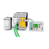
- Control Unit
- SIMOCODE pro
Manuals and User Guides for Siemens SIMOCODE pro. We have 5 Siemens SIMOCODE pro manuals available for free PDF download: Function Manual, Programming And Operating Manual, Operating Manual, Manual, Operating Instructions
Siemens SIMOCODE pro Function Manual (344 pages)
Industrial Controls, Motor management and control devices, Communication
Brand: Siemens
|
Category: Control Unit
|
Size: 4.95 MB
Table of Contents
-
Table of Contents
3
-
1 Introduction
7
-
Important Notes
7
-
Security Information
10
-
Current Information about Operational Safety
11
-
-
2 Communication
13
-
PROFIBUS Communication
13
-
Definitions
13
-
Data Transfer
15
-
Fail-Safe Data Transfer Via PROFIBUS / Profisafe
16
-
Telegram Description and Data Access
17
-
Cyclic Data
17
-
Diagnostics Data and Alarms
18
-
Structure of the Slave Diagnostics
19
-
Integration of SIMOCODE Pro in DP Master Systems
28
-
Slave Operating Modes
28
-
Preparing the Data Transfer
28
-
Integration of SIMOCODE Pro as a DPV1 Slave Via GSD in the Configuring Software
29
-
Integration of SIMOCODE Pro as a SIMATIC PDM Object (DPV1 Slave Via GSD) in STEP7 HW Config
31
-
Integration of SIMOCODE Pro as an S7 Slave Via OM SIMOCODE Pro
32
-
Compatibility of SIMOCODE Pro S and SIMOCODE Pro V
33
-
Evaluating Diagnostics Data
34
-
SIMOCODE Pro Integrated with GSD
34
-
Integration of SIMOCODE Pro in SIMATIC S7 with OM SIMOCODE es
36
-
Data Records
37
-
Parameterization Via PROFIBUS
38
-
SIMOCODE es Premium
38
-
Simatic Pdm
39
-
Parameter Data During Startup
40
-
Timestamping/Time Synchronization
40
-
PROFINET Communication
41
-
Definitions
41
-
Data Security in Automation
43
-
Data Transfer
45
-
Communication Via PROFINET IO
46
-
Integration of SIMOCODE Pro into the Automation System (PLC)
48
-
Integration of SIMOCODE Pro V PN Via GSD
51
-
Integration of SIMOCODE Pro V PN in SIMATIC STEP 7 V5 Via OM SIMOCODE Pro
52
-
Configuring SIMOCODE Pro V PN Ports
53
-
Configuration of Further Properties of SIMOCODE Pro V PN as an IO Device
54
-
Identification Data for PROFINET IO
57
-
Shared Device
58
-
Media Redundancy
58
-
System Redundancy
59
-
Diagnostics
65
-
Data Records
77
-
Profienergy
78
-
Further Communication Functions Via Ethernet
81
-
Modbus Communication
95
-
Modbus RTU Communication
95
-
Modbus RTU — General
95
-
Supported Data Transfer Rates for RTU
95
-
Assignment of SIMOCODE Data to Modbus Addresses with Modbus RTU
95
-
Modbus RTU Data Transfer
96
-
Modbus RTU Telegram Format
97
-
Modbus RTU Function Codes
98
-
Modbus RTU Error Codes
109
-
Ethernet/Ip Communication
110
-
Important Notes
110
-
Definitions
110
-
Data Security in Automation
112
-
Data Transmission
112
-
Electronic Data Sheet (EDS) File
113
-
Setting up the IP Address
114
-
Address Collision Detection (ACD)
115
-
Parameterizing the Device
116
-
Integrating SIMOCODE Pro into the Automation System (PLC)
117
-
Integration and Commissioning in Rockwell Studio 5000
118
-
Ethernet/Ip Device Level Ring Functionality
119
-
Ethernet/Ip System Redundancy
119
-
Web Diagnostics
120
-
Time-Of-Day Synchronization by the NTP Procedure
122
-
Simple Network Management Protocol (SNMP)
123
-
-
3 Tables, Data Records
125
-
Tables General
125
-
Active Control Stations, Contactor Controls, Lamp Controls and Status Information for the Control Functions
125
-
Assignment of Cyclic Receive and Send Data for Predefined Control Functions
128
-
Overload Relay
128
-
Direct Starter
129
-
Reversing Starter
130
-
Molded-Case Circuit Breaker (MCCB)
131
-
Star-Delta Starter
132
-
Star-Delta Reversing Starter
133
-
Dahlander Starter
134
-
Dahlander Reversing Starter
135
-
Pole-Changing Starter
136
-
Pole-Changing Reversing Starter
137
-
Solenoid Valve
138
-
Positioner
139
-
Soft Starter
140
-
Soft Starter with Reversing Contactor
141
-
Tables, PROFIBUS Data Records
142
-
PROFIBUS Tables
142
-
Abbreviations and Specifications
142
-
Socket Assignment Table — Digital
143
-
Socket Assignment Table — Analog
150
-
Detailed Messages of the Slave Diagnostics
153
-
PROFIBUS Data Records
157
-
PROFIBUS Data Records — General
157
-
Data Record 0/1 — S7 System Diagnostics
160
-
Data Record 63 — Analog Value Recording
162
-
Data Record 67 — Process Image Output
162
-
Data Record 69 — Process Image Input
163
-
Data Record 72 — Error Buffer
164
-
Data Record 73 — Event Memory
164
-
Data Record 92 — Device Diagnostics
165
-
Data Record 94 — Measured Values
172
-
Data Record 95 — Service Data/Statistical Data
174
-
Data Record 130 — Basic Device Parameters 1
175
-
Data Record 131 — Basic Device Parameters 2 (Plug Binary)
181
-
Data Record 132 — Extended Device Parameters 1
185
-
Data Record 133 — Extended Device Parameters 2 (Plug Binary)
193
-
Data Record 134 — Extended Device Parameters 2
196
-
Data Record 135 — Extended Device Parameters 2
196
-
Data Record 139 — Marking
197
-
Data Record 160 — Communication Parameters
198
-
Data Record 165 — Identification
198
-
Data Record 202 — Acyclic Receive
199
-
Data Record 203 — Acyclic Send
200
-
Data Record 224 — Password Protection
201
-
Tables, PROFINET Data Records
202
-
PROFINET Tables
202
-
OPC UA Variables
202
-
Abbreviations and Specifications
211
-
Socket Assignment Table — Digital
212
-
Socket Assignment Table — Analog
219
-
PROFINET Data Records
223
-
PROFINET Data Records — General
223
-
Data Record 63 — Analog Value Recording
226
-
Data Record 67 — Process Image Output
226
-
Data Record 69 — Process Image Input
227
-
Data Record 72 — Error Buffer
228
-
Data Record 73 — Event Memory
228
-
Data Record 92 — Device Diagnostics
229
-
Data Record 94 — Measured Values
238
-
Data Record 95 — Service Data/Statistical Data
240
-
Data Record 130 — Basic Device Parameters 1
242
-
Data Record 131 — Basic Device Parameters 2 (Plug Binary)
248
-
Data Record 132 — Extended Device Parameters 1
252
-
Data Record 133 — Extended Device Parameters 2 (Plug Binary)
260
-
Data Record 134 — Extended Device Parameters 2
263
-
Data Record 135 — Extended Device Parameters 2
269
-
Data Record 139 — Marking
272
-
Data Record 140 — Marking 2
273
-
Data Record 165 — Identification
274
-
Data Record 224 — Password Protection
274
-
Modbus Data Tables
275
-
General Information
275
-
Memory Image
275
-
Byte Arrangement
276
-
Specifications
276
-
Modbus RTU Data Tables
277
-
Process Image Output — Command Data
277
-
Process Image Input — Monitoring Data
278
-
Measured Values
279
-
Display and Statistical Data
281
-
Device Diagnostics
282
-
Error Memory
289
-
Event Memory
290
-
Trace Data
291
-
I&M0 — Device Identification
292
-
I&M1 Data
292
-
I&M2 — Installation Date
293
-
I&M3 — Comment
293
-
Basic Device Parameter 1
294
-
Extended Device Parameters 1
301
-
Marking
312
-
Ethernet/Ip Data Tables
313
-
Supported Objects
313
-
Identity Object
314
-
Message Router Object
316
-
Assembly Object
316
-
Connection Manager Object
327
-
Device Diagnosis Object
328
-
Measurement Object
329
-
Statistical Data Object
331
-
Motor Parameter Object
333
-
TCP/IP Interface Object
335
-
Ethernet Link Object
336
-
List of Abbreviations
337
-
A.1 List of Abbreviations
337
-
Index
339
-
-
Advertisement
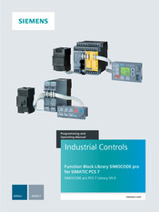
Siemens SIMOCODE pro Programming And Operating Manual (286 pages)
Industrial Controls, Function Block Library SIMOCODE pro
Brand: Siemens
|
Category: Control Unit
|
Size: 6.74 MB
Table of Contents
-
Table of Contents
4
-
SIMOCODE Pro PCS 7 Library V9.0 Programming and Operating Manual, 06/2017, A5E40899442002A/RS-AA/001
9
-
Introduction
10
-
Security Information
10
-
Product Specific Security Information
10
-
Components of the Software Package
11
-
Supported Control Functions
12
-
Configuration Steps
14
-
Configuring in HW Config
14
-
Configuring in CFC
16
-
Driver Generator
17
-
Requirements for Generating the Module Drivers
19
-
Driver Blocks
20
-
Object Lists and Action Lists
20
-
Example Configurations
21
-
SIMOCODE Pro PROFIBUS and PROFINET Configuration
21
-
SIMOCODE Pro PROFIBUS Configuration
21
-
SIMOCODE Pro PROFINET Configuration
24
-
Parameterization Softwares
32
-
Configuring in SIMOCODE es
32
-
Parameter Settings
34
-
Configuration with SIMATIC PDM
35
-
Device Type Selection in HW Config
35
-
Configuring of the Fail-Safe, Digital Profisafe Module
36
-
Update an Existing PCS 7 Project
37
-
Further Documentation
37
-
-
Templates
38
-
Overview of the Templates, Control Functions and Blocks
38
-
Using Templates
39
-
Template Ovlrly
42
-
Template Direct
43
-
Template Reverse
44
-
Template MCCB
45
-
Template Stardel
46
-
Template Revstardel
47
-
Template Dahland
48
-
Template Revdahl
49
-
Template Polechng
50
-
Template Revpolech
51
-
Template Solvalve
52
-
Template Positner
53
-
Template Softstr
54
-
Template Revsoftstr
55
-
Sample Project
55
-
-
Block Icons and Faceplate Views
56
-
Block Icons
56
-
Faceplates
58
-
Faceplates — Structure
58
-
Navigation between SIMOCODE Pro Faceplates
61
-
Views
62
-
Batch View
62
-
Trend View
63
-
Alarm View
65
-
Memo View
66
-
Preview View
67
-
Scalable Faceplates
67
-
Central Color Management
69
-
Web Navigator
70
-
APL Operator Trend Control (AOTC) for Digital Values
71
-
-
Description of the Blocks
72
-
Functions for All Blocks
72
-
Calling Obs
72
-
Called Blocks
73
-
Worst Signal Status
74
-
Quality Code
75
-
Error Numbers
77
-
Reading and Writing Data Records
78
-
Read Record Error Status
79
-
Write Record Error Status
79
-
Overview of the Measuring Point Browser Window
79
-
Configurable Response Using the Feature I/O
80
-
Start-Up Characteristics
80
-
Response for out of Service Mode
81
-
Resets the Commands for Switching between Modes
81
-
Enabling Resetting of Commands for the Control Settings
82
-
Setting Switch or Button Mode
82
-
Set Switching Mode
83
-
Enabling Direct Changeover between Forward and Reverse
83
-
Resetting Via Input Signals in the Event of Interlocking (Protection) or Errors
84
-
Exit Local Mode
84
-
Enable Runtime for Feedback Signals
84
-
Separate Monitoring Time for Stopping the Motor
85
-
Enabling Rapid Stop Via Faceplate
85
-
Activate Bumpless Changeover to Automatic Mode
85
-
Activate Fault Status for External Control System Fault
86
-
Reset Even in Locked State
86
-
Disable Feedback Tracking Localsetting 2 & 4
86
-
Bumpless Switchover to Automatic Mode
87
-
Update Acknowledgement and Error Status of the Alarm
87
-
Activate Local Operator Permission
87
-
Suppression of All Messages
88
-
Interlock Display with Localsetting 2 or 4
88
-
Define Reset as a Function of the Mode
88
-
Enable Reset of Interlocks in Manual Mode
90
-
Suppression of Single Alarm Message
91
-
Resetting Control in Case of Invalid Command
91
-
Setting Switch or Button Mode for Local Commands
91
-
Evaluation of the Signal Status of the Interlock Signals
92
-
Forcing Operating Modes in the «Local» Mode
93
-
Considering Bad Quality of Automatic Commands or External Values
93
-
Separate Interlock for each Direction or Position
93
-
Diagnostics Block Mmdiag
94
-
Description of Mmdiag
94
-
Acyclic Reading of Data Record 92
95
-
Message Characteristics
95
-
Driver Generator
96
-
Start-Up Characteristics
97
-
Module Error
97
-
IO Station Failure (PROFIBUS DP or PROFINET IO)
98
-
Failure of a PROFIBUS DP Station
99
-
Malfunction When Loading the ob
99
-
Mmoprtn Block
100
-
Description of Mmoprtn
100
-
Parameterizable Functions Via the Feature Connection Mmoprtn
101
-
Operating Modes
102
-
Motor Current
103
-
Device Functions
103
-
Current Limits
106
-
Hysteresis
107
-
Emergency Start
107
-
Self-Test
108
-
Trip Reset
109
-
Group Fault
109
-
Fault Handling
110
-
Invalid Input Signals
110
-
Message Characteristics
110
-
Messages Via Event16Ts Message Block
111
-
System Text Libraries for Warning and Trip
113
-
Process Images for the Mmoprtn Block
116
-
Enabled Operations
130
-
Status Information
131
-
SIMOCODE Pro Slave Diagnostics
132
-
-
Diagnostics Information
133
-
Assignment of the Diagnostics Information
140
-
Faceplate Views
148
-
Mmoprtn — Standard
148
-
Mmoprtn — Limits
150
-
Mmoprtn — Diagnostics
152
-
Mmoprtn — Process Image
153
-
Block for Mmmeas Measured Value Function
154
-
Description of Mmmeas
154
-
Parameterizable Functions Via the Feature Connection Mmmeas
155
-
Operating Modes
155
-
Measured Values
156
-
Read Measured Values
158
-
Assignment of the Cyclic Process Image
159
-
Write Analog Output
160
-
Acyclic Reading
160
-
Message Characteristics
161
-
Start-Up Characteristics
162
-
Status Information
163
-
Enabled Operations
164
-
Faceplate Views
165
-
Mmmeas Standard
165
-
Mmmeas — Standard 1
166
-
Mmmeas — Standard 2
167
-
Mmmeas — Standard 3
169
-
Mmmeas — Standard 4
170
-
Block for Statistical Function Mmstat
172
-
Description of Mmstat
172
-
Parameterizable Functions Via the Feature Connection Mmstat
173
-
Operating Modes
173
-
Statistical Values
173
-
Message Characteristics
175
-
Start-Up Characteristics
176
-
Status Information
177
-
Enabled Operations
178
-
Faceplate Views
179
-
Mmstat — Standard 1
179
-
Mmstat — Standard 2
181
-
Block for Timestamping Mmlog
183
-
Description Mmlog
183
-
Parameterizable Functions Via the Feature Connection Mmlog
184
-
Operating Modes
184
-
Logbook Function
185
-
Messages
188
-
Signaling Response
190
-
Driver Generator
192
-
Start-Up Characteristics
192
-
Status Information
192
-
Enabled Operations
194
-
Faceplate Views
194
-
Mmlog — Standard
194
-
Mmlog — Logbook
195
-
Mmrevdhl Motor Block
197
-
Application
197
-
Description of Mmrevdhl
197
-
Operating Modes
198
-
Mode Changeover Error
200
-
Forcing Operating Modes
201
-
Control Functions for Directions
202
-
Parameterizable Functions Via the Feature Connection Mmrevdhl
203
-
Output Signal for Ready to Start
204
-
Resetting of the Block
204
-
Limit Value Monitoring with Hysteresis
205
-
Rapid Stop
205
-
Specify Warning Times for Controls
205
-
Issuing Maintenance Release
206
-
Suppressing Messages Using the Msglock Parameter
206
-
Simulation
206
-
Monitoring Functions
207
-
Motor Protection
209
-
Interlocking
209
-
Disabling Interlocks
212
-
Group Fault
212
-
User-Defined Auxiliary Values and User-Defined Status
213
-
Message Characteristics
213
-
Fault Handling
216
-
Invalid Input Signals
216
-
Enable for Measurement and Statistics
216
-
Enabled Operations
216
-
Status Information
218
-
Time
221
-
Restart Lock after Changing Direction of Rotation or Switching off the Motor Using Idle Time
221
-
Selecting a Unit of Measure
222
-
Faceplate Views
223
-
Mmrevdhl — Standard
223
-
Mmrevdhl — Maintenance
225
-
Mmrevdhl — Preview
227
-
-
Maintenance Station
230
-
Parameter
234
-
Mmdiag Block Parameter
234
-
A.1 Mmdiag Block Parameter
234
-
Structure of Udts for Mmdiag
237
-
Block Parameter Mmoprtn
244
-
Block Parameter Mmmeas
252
-
Block Parameter Mmstat
260
-
Block Parameter Mmlog
267
-
Block Parameter Mmrevdhl
273
-
Technical Data
283
-
B.1 Header Information
284
-
-

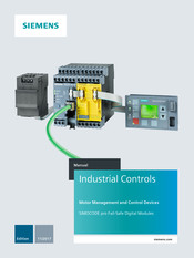
Siemens SIMOCODE pro Operating Manual (278 pages)
Industrial Controls, Motor management and control
devices
Brand: Siemens
|
Category: Control Unit
|
Size: 11.86 MB
Table of Contents
-
Table of Contents
4
-
1 Introduction
7
-
Important Information
7
-
Security Information
10
-
Current Information about Operational Safety
11
-
-
2 Function Blocks
12
-
Function Blocks — Input and Output Types, Structure
12
-
Function Blocks — Overview
15
-
-
3 Software for Parameterization, Control, Diagnostics and Testing
24
-
Software Packages
24
-
Software Components
28
-
-
4 Parameters
31
-
Motor Protection
31
-
Motor Protection Functions
31
-
Overload Protection
34
-
Description of Overload Protection Functions
34
-
Set Current Is1
34
-
Set Current Is2
35
-
Application Example
37
-
Further Overload Protection Parameters
38
-
Unbalance Protection
48
-
Stalled Rotor Protection
49
-
Thermistor Protection
50
-
Motor Control
52
-
Control Stations
52
-
Description of Functions of Control Stations
52
-
Operating Modes and Mode Selectors
56
-
Enables and Enabled Control Command
58
-
Control Station Settings
60
-
Control Functions
61
-
Overview and Description of Control Functions
61
-
Application Selection, Settings and Definitions of Control Functions
66
-
Overload Relay» Control Function
72
-
Direct Starter» Control Function
74
-
Reversing Starter» Control Function
76
-
Molded Case Circuit Breaker (MCCB)» Control Function
79
-
Star-Delta Starter» Control Function
82
-
Star Delta Reversing Starter» Control Function
86
-
Dahlander» Control Function
90
-
Dahlander Reversing Starter» Control Function
93
-
Pole-Changing Starter» Control Function
97
-
Pole-Changing Reversing Starter» Control Function
100
-
Solenoid Valve» Control Function
104
-
Positioner» Control Function
107
-
Soft Starter» Control Function
112
-
Soft Starter with Reversing Contactor» Control Function
115
-
Active Control Stations, Contactor Controls, Lamp Controls and Status Information for the Control Functions
119
-
Monitoring Functions
122
-
Ground Fault Monitoring
122
-
Description of Functions of Ground-Fault Monitoring
122
-
Limits of Fault Current Measurement
125
-
Internal Ground-Fault Monitoring When Using a 2Nd Generation Current / Voltage
127
-
Measuring Module
127
-
Internal Ground-Fault Monitoring When Using a Current Measuring Module or a 1St Generation Current / Voltage Measuring Module
130
-
External Ground-Fault Monitoring with a 3UF7500 Ground-Fault Module and 3UL22 Differential Current Transformer
131
-
External Ground-Fault Monitoring with a 3UF7510 Ground-Fault Module and 3UL23 Residual Current Transformer
132
-
Current Limit Monitoring
135
-
Description of Functions of Current Limit Monitoring
135
-
I> (Upper Limit)
136
-
I< (Lower Limit)
138
-
Voltage Monitoring
140
-
Cos Phi Monitoring
143
-
Active Power Monitoring
145
-
0/4
147
-
Operation Monitoring
150
-
Description of Functions of Operation Monitoring
150
-
Operating Hours Monitoring
152
-
Motor Stop Time Monitoring
153
-
Monitoring the Number of Starts
154
-
Temperature Monitoring (Analog)
156
-
Monitoring Interval for Mandatory Testing
159
-
Hysteresis for Monitoring Functions
160
-
Outputs
161
-
Overview of Outputs
161
-
Basic Unit Outputs
163
-
Operator Panel Leds
165
-
Digital Module Outputs
168
-
Analog Module Output
170
-
Cyclic Send
177
-
Acyclic Send
179
-
OPC-UA Send
180
-
Inputs
181
-
Overview of Inputs
181
-
Basic Unit Inputs
184
-
Operator Panel Buttons
186
-
Digital Module Inputs
188
-
Temperature Module Inputs
192
-
Analog Module Inputs
194
-
Cyclic Receive
196
-
Acyclic Receive
197
-
OPC UA Receive
198
-
Analog Value Recording
199
-
Analog Value Recording Description of Functions
199
-
Measured Curve, Function Block and Analog Value Recording Application Example
200
-
Standard Functions
202
-
Overview of Standard Functions
202
-
Test / Reset
204
-
Test Position Feedback (TPF)
208
-
External Fault
210
-
Operational Protection off (OPO)
213
-
Response to Positioner Control Function
213
-
Response to Other Control Functions
215
-
Power Failure Monitoring (UVO)
216
-
Emergency Start
219
-
Safety-Oriented Tripping
220
-
Watchdog (Bus Monitoring, PLC/PCS Monitoring)
227
-
Timestamping
230
-
Logic Modules
232
-
Overview of Logic Modules
232
-
Truth Table for 3I / 1O
234
-
Truth Table for 2I / 1O
237
-
Truth Table for 5I / 2O
239
-
Counter
240
-
Timer
242
-
Signal Conditioner
247
-
Non-Volatile Elements
251
-
Flashing
254
-
Flickering
255
-
Limit Monitor
256
-
Calculators (Calculation Modules) 1, 2
261
-
Calculators (Calculation Modules) 3, 4
265
-
Analog Multiplexer
267
-
Pulse Width Modulator
269
-
-
List of Abbreviations
272
-
A.1 List of Abbreviations
272
-
Index
273
-
-
Advertisement
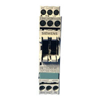
Siemens SIMOCODE pro Manual (118 pages)
Fail-Safe Digital Modules
Brand: Siemens
|
Category: Control Unit
|
Size: 3.69 MB
Table of Contents
-
Table of Contents
5
-
SIMOCODE Pro — Fail-Safe Digital Modules Manual, 11/2017, NEB631679702000/RS-AA/002
7
-
1 Introduction
9
-
Important Information
9
-
Security Information
12
-
Current Information about Operational Safety
12
-
-
2 Safety Notes
13
-
Liability Disclaimer
13
-
Support
14
-
-
3 SIMOCODE Pro Safety
15
-
Overview of Functions
16
-
Device Versions
16
-
Failsafe DM-F LOCAL Digital Module
17
-
Failsafe DM-F Profisafe Digital Module
20
-
-
4 Mounting and Connection
23
-
General Mounting and Wiring Instructions
23
-
Mounting
24
-
Connecting
27
-
-
5 Operation
29
-
DM-F Local
29
-
Terminals and Their Meaning
29
-
Leds, Buttons, and Their Meanings
31
-
DM-F Profisafe
35
-
Terminals and Their Meaning
35
-
Leds, Buttons, and Their Meanings
37
-
-
6 Planning/Configuring
39
-
General Remarks
39
-
Configuring the DM-F LOCAL
40
-
Device Functions of the DM-F LOCAL
41
-
Flow Diagram of the DM-F LOCAL Configuration
42
-
Interrupt, Error, and System Messages on the DM-F LOCAL
45
-
Configuring the DM-F Profisafe and Integrating It into the Fail-Safe Automation System Using Profibus/Profisafe or Profinet/Profisafe
46
-
Interrupt, Error, and System Messages on DM-F Profisafe
54
-
-
7 Service and Maintenance
55
-
Replacing a DM-F
55
-
-
8 External Circuitry
57
-
Sensor Circuitry for the DM-F LOCAL
57
-
-
9 Typical Circuit Diagrams
59
-
Introduction
59
-
DM-F Local, Sensor Circuits
63
-
DM-F LOCAL, 2-Channel, with Cross-Circuit Detection and Monitored Start
64
-
DM-F LOCAL, 2-Channel, with Cross-Circuit Detection and Automatic Start
65
-
DM-F Local, NC and no Contacts, with Cross-Circuit Detection and Monitored Start
66
-
DM-F LOCAL, NC and no Contacts, with Cross-Circuit Detection and Automatic Start
67
-
DM-F LOCAL in Conjunction with Failsafe Electronic Outputs (Current Sourcing / Current Sinking) with Monitored Start
68
-
DM-F LOCAL in Conjunction with Failsafe Electronic Outputs (Current Sourcing) with Automatic Start
69
-
DM-F LOCAL, 2 X 1-Channel, Without Cross-Circuit Detection, with Monitored Start
70
-
DM-F LOCAL, 2 X 1-Channel, Without Cross-Circuit Detection, with Automatic Start
71
-
DM-F LOCAL, Actuator Circuits
72
-
Actuator Circuit with Feedback Circuit, Control Function = Direct Starter
72
-
Actuator Circuit with Feedback Circuit, Control Function = Reversing Starter
74
-
Actuator Circuit with Feedback Circuit, Control Function = Star-Delta Starter
76
-
Actuator Circuit with Feedback Circuit, Control Function = Dahlander Starter
78
-
Actuator Circuit with Feedback Circuit, Control Function = Pole-Changing Starter
80
-
DM-F Profisafe, Actuator Circuits
82
-
Connection Examples for DM-F Profisafe, Actuator Circuit
82
-
Actuator Circuit with Feedback Circuit, Control Function = Direct Starter
82
-
Actuator Circuit with Feedback Circuit, Control Function = Reversing Starter
84
-
Actuator Circuit with Feedback Circuit, Control Function = Star-Delta Starter
86
-
Actuator Circuit with Feedback Circuit, Control Function = Dahlander Starter
88
-
Actuator Circuit with Feedback Circuit, Control Function = Pole-Changing Starter
90
-
-
10 Technical Data
93
-
Technical Data of the DM-F Local and DM-F Profisafe Fail-Safe Digital Modules
93
-
Technical Data of the DM-F Local Fail-Safe Digital Module
96
-
Technical Data of the DM-F Profisafe Fail-Safe Digital Module
98
-
Safety-Specific Technical Data of the DM-F Local Fail-Safe Digital Module
99
-
Monitoring and Response Times of the DM-F Local Fail-Safe Digital Module
101
-
Safety-Specific Technical Data of the DM-F Profisafe Fail-Safe Digital Module
102
-
Monitoring and Response Times of the DM-F Profisafe Fail-Safe Digital Module
102
-
Technical Data in Siemens Industry Online Support
103
-
List of Abbreviations
105
-
A.1 List of Abbreviations
105
-
Glossary
107
-
Index
115
-
-
Siemens SIMOCODE pro Operating Instructions (4 pages)
Digital Module
Brand: Siemens
|
Category: Control Unit
|
Size: 0.53 MB
Advertisement
Related Products
-
Siemens SIMOCODE pro PCS 7
-
Siemens SIMOCODE pro C
-
Siemens SIMOCODE pro S
-
Siemens SIMOCODE pro V PB
-
Siemens SIMOCODE pro V MR
-
Siemens SIMOCODE pro V EIP
-
Siemens SIMOCODE DP
-
Siemens SIMOCODE DP PCS 7
-
Siemens SIMOCODE pro DM-F Local
-
Siemens SIMODRIVE
Siemens Categories
Controller
Control Unit
Industrial Equipment
![]()
Washer
![]()
Switch
More Siemens Manuals
- Manuals
- Brands
- Siemens Manuals
- Water Pump
- SIMOCODE pro V
- Manual
-
Contents
-
Table of Contents
-
Bookmarks
Quick Links
Prevention of pump
blockages by
changing the
direction of rotation
SIMOCODE pro V
https://support.industry.siemens.com/cs/ww/en/view/109478058
Siemens
Industry
Online
Support
Related Manuals for Siemens SIMOCODE pro V
Summary of Contents for Siemens SIMOCODE pro V
-
Page 1
Prevention of pump blockages by changing the direction of rotation Siemens SIMOCODE pro V Industry Online https://support.industry.siemens.com/cs/ww/en/view/109478058 Support… -
Page 2: Legal Information
The foregoing provisions do not imply any change in the burden of proof to your detriment. You shall indemnify Siemens against existing or future claims of third parties in this connection except where Siemens is mandatorily liable.
-
Page 3: Table Of Contents
Commissioning ………………. 27 Parameterization …………….28 3.3.1 Creating the hardware configuration ……….29 3.3.2 Parameter assignment for the SIMOCODE pro V PN ……. 31 3.3.3 Compile parameterization …………..53 Operation ……………….. 54 3.4.1 General remarks on Monitoring and Control ……..54 3.4.2…
-
Page 4: Introduction
With SIMOCODE pro, you can prevent faults in the system and recognize impending failures before they happen. This application example will help you to minimize maintenance deployments. Blocking Protection for Pumps with SIMOCODE pro V Article ID: 109478058, V2.0, 09/2020…
-
Page 5: Delimitation
You will also need basic knowledge of SIMOCODE pro. The ability to work with the SIMOCODE ES options package in TIA Portal is a plus. Blocking Protection for Pumps with SIMOCODE pro V Article ID: 109478058, V2.0,…
-
Page 6: Components Used
If your application can go without evaluating the power factor, cos φ, it is also possible to use a pure current measuring module 3UF10x-1yA00-0. However, in that case you must replace the measuring module in the device configuration in the project engineering of the supplied example. Blocking Protection for Pumps with SIMOCODE pro V Article ID: 109478058, V2.0,…
-
Page 7
If the operator panel is left out, it should be deleted from the device configuration in the project engineering of the included example. Blocking Protection for Pumps with SIMOCODE pro V Article ID: 109478058, V2.0,… -
Page 8
Standard Floating License (Download) Driver for SIRIUS USB free download (see 9) includes installation PC cable 3UF7941- instructions 0AA00-0 Note Other minor materials have not been listed here. Blocking Protection for Pumps with SIMOCODE pro V Article ID: 109478058, V2.0, 09/2020… -
Page 9: Operating Principle
© Siemens AG 2020 All rights reserved 2 Operating principle Operating principle Figure 2-1 Blocking Protection for Pumps with SIMOCODE pro V Article ID: 109478058, V2.0, 09/2020…
-
Page 10: Logic Blocks In Use
«true». The counter can be reset to 0 with the reset input (R). The counter value is available as an output. Detailed information is available in manual 3. Figure 2-3 Counter 1 Value Blocking Protection for Pumps with SIMOCODE pro V Article ID: 109478058, V2.0, 09/2020…
-
Page 11
0.5 s for all limit monitors in the example. Detailed information is available in manual 3. Figure 2-6 Limit monitor 1 Blocking Protection for Pumps with SIMOCODE pro V Article ID: 109478058, V2.0, 09/2020… -
Page 12: Explanation Of The Logic
«Protection/Control» (marked in orange in Figure 2-1 Figure 2-8). The enabled command «OFF» from Control station remains connected with the «OFF» plug of «Protection/Control». Figure 2-8 Blocking Protection for Pumps with SIMOCODE pro V Article ID: 109478058, V2.0, 09/2020…
-
Page 13: Detecting Faults In The Conveying Flow
The logic in the SIMOCODE pro V PN basic unit detects a problem in the pumped flow if one of the following conditions is met: •…
-
Page 14: Switching On Via The Control Station
The «ON<» command supplied by the «Control station» function block is passed to the «Protection/Control» function block via input 2 of truth table TT7. Due to the default parameterization «Non-maintained command mode», the control command is stored. Blocking Protection for Pumps with SIMOCODE pro V Article ID: 109478058, V2.0, 09/2020…
-
Page 15: Shutting Off Via The Control Station Or In The Event Of A Fault
Timer 1. For this purpose, the enabled «OFF» command at the output of the «Control station» function block is interconnected with the reset input of Timer 1 via truth tables TT5 and TT8. Blocking Protection for Pumps with SIMOCODE pro V Article ID: 109478058, V2.0,…
-
Page 16: Manual Reversal In The Other Direction Of Rotation
Timer 1. For this purpose, the enabled «ON>» command at the output of the «Control station» function block is interconnected with the reset input of Timer 1 via truth tables TT5 and TT8. Blocking Protection for Pumps with SIMOCODE pro V Article ID: 109478058, V2.0,…
-
Page 17: Reversal In The Opposite Direction When Conveying Fault Has Been Detected
Test/Reset button on the SIMOCODE operator panel is pressed («Test/Reset button» socket of the «OP buttons» function block) • Acknowledgment via a PLC (socket for bit 6 of the function block «Cyclic receive Byte 0») Blocking Protection for Pumps with SIMOCODE pro V Article ID: 109478058, V2.0, 09/2020…
-
Page 18: Resetting The Fault Counter During Operation
4 of truth table TT9. If the PLC transmits «false» or if no PLC is connected, then the blockage prevention logic is active. If «true», the limit monitors 2, 3 and 4 are not evaluated (see chapter 2.2.2). Blocking Protection for Pumps with SIMOCODE pro V Article ID: 109478058, V2.0,…
-
Page 19
«+» plug of Counter 2 (see chapter 2.2.6). After an overflow (>65535), the counter begins at 0 again. Blocking Protection for Pumps with SIMOCODE pro V Article ID: 109478058, V2.0,… -
Page 20: Engineering
SIMOCODE system wiring PROFINET / IE SIMOCODE pro V PN (basic unit) Digital module Operator panel SIRIUS circuit breaker Current / voltage measuring module SIRIUS contactor combination PG/PC Blocking Protection for Pumps with SIMOCODE pro V Article ID: 109478058, V2.0, 09/2020…
-
Page 21: Basic Unit (Bu)
3.1.1 Basic unit (BU) A SIMOCODE pro V PN motor control device is built into the application example with a PROFINET interface. However, you can also use basic units with PROFIBUS interface or MODBUS RTU. The basic parameterization matches a reversing starter.
-
Page 22: Installation And Commissioning
6. If you do not need status signaling for local control, you can remove the digital module from the configuration. In the device configuration for «Control device_1», right-click the digital module and select «Delete» in the context menu. Blocking Protection for Pumps with SIMOCODE pro V Article ID: 109478058, V2.0, 09/2020…
-
Page 23: Installing The Software
8. Connect the source system (PG/PC) with one of the following interfaces of the SIMOCODE pro motor management system. – SIMOCODE system interface of the SIMOCODE pro V PN basic unit or of the operator panel In this application example, the SIMOCODE system interface of the operator panel free to connect the source system (PG/PC) via the SIRIUS USB PC cable.
-
Page 24: Downloading Configuration And Parameterization To The Simocode Pro V Pn Basic Unit
PN basic unit in the following ways: 1. via the PROFINET interface of the SIMOCODE pro V PN basic unit 2. via the SIMOCODE system interface of the SIMOCODE pro V PN basic unit or operator panel Downloading via the PROFINET interface of the SIMOCODE pro V PN basic unit…
-
Page 25
The download process will be aborted with an error if the SIMOCODE device is in the «Remote/Automatic» operating mode, if an «ON» command is pending, or if the motor is running. Blocking Protection for Pumps with SIMOCODE pro V Article ID: 109478058, V2.0,… -
Page 26
Downloading via the SIMOCODE system interface If the source system (PG/PC) is connected to the SIMOCODE system interface of the SIMOCODE pro V PN or operator panel via the SIRIUS USB PC cable, proceed according to the following instructions: 1. Select the SIMOCODE device in the project tree. -
Page 27: Commissioning
3-phase mains or switch on the SIRIUS circuit breaker. For information on operating the application example, refer to chapter 3.4. Blocking Protection for Pumps with SIMOCODE pro V Article ID: 109478058, V2.0,…
-
Page 28: Parameterization
Configuration in TIA Portal offers some freedom. The following parameterization Note represents one possible solution. Other more or less similar actions can achieve the same goal. Blocking Protection for Pumps with SIMOCODE pro V Article ID: 109478058, V2.0, 09/2020…
-
Page 29: Creating The Hardware Configuration
The hardware and network editor will open. 2. Select the «Network view». 3. Drag and drop the SIMOCODE pro V PN (in the version you are using) from the Task Card «Hardware catalog» into the graphical area of the Network view.
-
Page 30
Card to the respective slots in the graphical area of the device view. – Current/voltage measuring module: IUM V2 0.3-4A – Digital module: DM mono – Operator panel: BBD Figure 3-3 Blocking Protection for Pumps with SIMOCODE pro V Article ID: 109478058, V2.0, 09/2020… -
Page 31: Parameter Assignment For The Simocode Pro V Pn
3 Engineering 3.3.2 Parameter assignment for the SIMOCODE pro V PN PROFINET parameters 1. Double-click the «Parameters» command in the project tree. 2. Go to «PROFINET parameters» and enter the following parameters. – IP parameters – Select Basic type 3 so that you can transmit all of the send data described 2.2.11…
-
Page 32
Because the SIMOCODE device is not networked with a controller, it also appears in the project tree under «Unassigned devices» and is marked as «Not assigned» in the Network view. Blocking Protection for Pumps with SIMOCODE pro V Article ID: 109478058, V2.0,… -
Page 33
For Class 10, the start procedure is defined from 10 s. 4. Make sure that the behavior in the event of a stalled rotor is set as «deactivated». Blocking Protection for Pumps with SIMOCODE pro V Article ID: 109478058, V2.0, 09/2020… -
Page 34
3 Engineering Figure 3-5 Motor control 1. Switch to «Motor control > Control station». Blocking Protection for Pumps with SIMOCODE pro V Article ID: 109478058, V2.0, 09/2020… -
Page 35
2. For the commands «ON>», «OFF» and «ON<«, create the following three control elements as per the image above: – «Local control»: Inputs 1-3 of the SIMOCODE pro V PN basic unit (BU inputs) Reverse direction «OFF» Forward direction «ON<» (input 1) (input 2) «ON>»… -
Page 36
3 Engineering Blocking Protection for Pumps with SIMOCODE pro V Article ID: 109478058, V2.0, 09/2020… -
Page 37
3. Interconnect LEDs 2-4 of the operator panel with the following plugs of the «Protection/Control» function block. – LED 2: Plug «QLE< (ON)» – LED 3: Plug «QLE> (ON>)» – LED 4: Plug «QLA (OFF)» Blocking Protection for Pumps with SIMOCODE pro V Article ID: 109478058, V2.0, 09/2020… -
Page 38
2. Interconnect outputs 1 and 2 of the digital module (DM outputs) with the following plugs of the «Protection/Control» function block. – DM output 1: Plug «QLA (OFF)» – DM output 2: Plug «QLE> (ON>)» Figure 3-8 Blocking Protection for Pumps with SIMOCODE pro V Article ID: 109478058, V2.0, 09/2020… -
Page 39
3. Interconnect the values of Counters 1 and 2 used in the logic to inputs 1 and 2 of the interface «Cyclic send byte 4/9». Figure 3-9 Blocking Protection for Pumps with SIMOCODE pro V Article ID: 109478058, V2.0, 09/2020… -
Page 40
3. For response, program «trip». 4. Create a label that will appear in the event of an error (for example on an operator panel with display). Figure 3-10 Blocking Protection for Pumps with SIMOCODE pro V Article ID: 109478058, V2.0, 09/2020… -
Page 41
2. Under «Logic modules > Truth table 3I/1O > Truth table 2», define the signals and logic of truth table 2 (TT2). The unused input 3 is set by default as «false». & (false) Blocking Protection for Pumps with SIMOCODE pro V Article ID: 109478058, V2.0, 09/2020… -
Page 42
3 (TT3). ≥1 4. Under «Logic modules > Truth table 3I/1O > Truth table 4», define the signals and logic of truth table 4 (TT4). & ≥1 & Blocking Protection for Pumps with SIMOCODE pro V Article ID: 109478058, V2.0, 09/2020… -
Page 43
5 (TT5). ≥1 6. Under «Logic modules > Truth table 3I/1O > Truth table 6», define the signals and logic of truth table 6 (TT6). ≥1 Blocking Protection for Pumps with SIMOCODE pro V Article ID: 109478058, V2.0, 09/2020… -
Page 44
7 (TT7). ≥1 8. Under «Logic modules > Truth table 2I/1O > Truth table 8», define the signals and logic of truth table 8 (TT8). & Blocking Protection for Pumps with SIMOCODE pro V Article ID: 109478058, V2.0, 09/2020… -
Page 45
3 Engineering 9. Under «Logic modules > Truth table 5I/2O > Truth table 9», define the signals and logic of truth table 9 (TT9). ≥1 & Blocking Protection for Pumps with SIMOCODE pro V Article ID: 109478058, V2.0, 09/2020… -
Page 46
2. Define the following parameters under «Logic modules > Counter > Counter 2». – Limit value: 65535 – Input + (increment): Output Timer 1 – Reset: Output Counter 2 Blocking Protection for Pumps with SIMOCODE pro V Article ID: 109478058, V2.0, 09/2020… -
Page 47
3. Define the following parameters under «Logic modules > Counter > Counter 3». – Limit value: 2 – Input + (increment): OP button 1 – Reset: Output Counter 3 Blocking Protection for Pumps with SIMOCODE pro V Article ID: 109478058, V2.0, 09/2020… -
Page 48
2. Define the following parameters under «Logic modules > Timer > Timer 2». – Type: «with closing delay» – Limit value: 3600.0 – Input: Output signal conditioning 2 – Reset: Output Timer 1 Blocking Protection for Pumps with SIMOCODE pro V Article ID: 109478058, V2.0, 09/2020… -
Page 49
3. Define the following parameters under «Logic modules > Signal conditioning > Signal conditioning 3». – Type: «edge rising with memory» – Input: OP button 1 – Reset: Output Counter 3 Blocking Protection for Pumps with SIMOCODE pro V Article ID: 109478058, V2.0, 09/2020… -
Page 50
The limit monitor should always be active («always (on)») The limit should be specified in %, based on the motor current at the input plug. If necessary, assign a label. Blocking Protection for Pumps with SIMOCODE pro V Article ID: 109478058, V2.0,… -
Page 51
(«if motor is running, except TPF, with startup override (run+)»). The limit should be specified in %, based on the motor current at the input plug. If necessary, assign a label. Blocking Protection for Pumps with SIMOCODE pro V Article ID: 109478058, V2.0, 09/2020… -
Page 52
(«if motor is running, except TPF, with startup override (run+)»). The limit should be specified in %, based on the motor current at the input plug. Add a label is necessary. Blocking Protection for Pumps with SIMOCODE pro V Article ID: 109478058, V2.0, 09/2020… -
Page 53: Compile Parameterization
Figure 3-11 Note If necessary, complete your configuration by networking the SIMOCODE pro V PN as a PROFINET IO device with a controller (PROFINET IO controller) that is also configured in TIA Portal. You thus have read and write access to the interconnected cyclic receive and send data.
-
Page 54: Operation
The LED «GEN.FAULT» will blink red. – The External fault 1 will be shown on the screen with the text «Blocked». The fault is acknowledged with the softkey on the right. Blocking Protection for Pumps with SIMOCODE pro V Article ID: 109478058, V2.0, 09/2020…
-
Page 55
You might see the dialog for advanced online connection, which is largely the same as the «Extended download to device» dialog. Follow the instructions there, start searching for the SIMOCODE device and click «Connect» to close the dialog. Blocking Protection for Pumps with SIMOCODE pro V Article ID: 109478058, V2.0,… -
Page 56
The following menus are relevant for these scenarios • «Faults» If a blockage can`t be cleared, the parameterized «External fault 1» will be displayed in the menu «Faults». Blocking Protection for Pumps with SIMOCODE pro V Article ID: 109478058, V2.0, 09/2020… -
Page 57
In the «Measured values» menu you can monitor the live values for current and power factor in order to compare them with the programmed limits of the limit monitors. Blocking Protection for Pumps with SIMOCODE pro V Article ID: 109478058, V2.0,… -
Page 58
«Service data / statistical data» In the «Service data / statistical data» menu you can monitor the live values of the timers and counters in the stall prevention logic. Blocking Protection for Pumps with SIMOCODE pro V Article ID: 109478058, V2.0,… -
Page 59: Scenarios
2. Check whether Counter 1 has the value «0». In order to reset Counter 1 to the value «0», perform a fault acknowledge operation (RESET), e.g. with the «TEST/RESET» button on the SIMOCODE pro V PN basic unit. 3. Start the drive with «ON>» (conveying direction).
-
Page 60
3 Engineering 6. Acknowledge the fault in one of the following ways: – Press the «TEST/RESET» button on the SIMOCODE pro V PN basic unit. – Press the right-hand softkey on the operator panel. – Transmit the value «true» via PROFINET at bit 6 of the interface «Cyclic receive byte 0». -
Page 61
The «External fault 1» alarm will appear in TIA Portal in the online view under «Commissioning > Faults». 7. Acknowledge the fault in one of the following ways: – Press the «TEST/RESET» button on the SIMOCODE pro V PN basic unit. – Press the right-hand softkey on the operator panel. –… -
Page 62: Useful Information
4 Useful information Useful information Time stamping SIMOCODE pro V can time stamp digital signals. In this case, any change of signal is recorded. It is possible to log the following signals, for instance for statistical analysis: • automatic reversal run (output of Timer 1) •…
-
Page 63: Appendix
Industry Online Support Do you have any questions or need assistance? Siemens Industry Online Support offers round the clock access to our entire service and support know-how and portfolio. The Industry Online Support is the central address for information about our products, solutions and services.
-
Page 64: Links And Literature
Date Change V1.0 08/2015 First edition V2.0 09/2020 Complete revision • Update for SIMOCODE pro V PN • Update for SIMOCODE ES V16 and TIA Portal V16 Blocking Protection for Pumps with SIMOCODE pro V Article ID: 109478058, V2.0, 09/2020…
Note for Owners:
Guidesimo.com webproject is not a service center of Siemens trademark and does not carries out works for diagnosis and repair of faulty Siemens SIMOCODE pro V equipment. For quality services, please contact an official service center of Siemens company. On our website you can read and download documentation for your Siemens SIMOCODE pro V device for free and familiarize yourself with the technical specifications of device.
More Water Pump Devices:
-
Xylem Rule 56D
Standard Bilge PumpINSTRUCTION MANUALFRDEITNLSEESManuel d’utilisation pour pompe de cale standardBedienungsanleitung für die Standard-BilgenpumpeManuale delle istruzioni per la pompa di sentina standardManual de instrucciones de la bomba de achique estándarAnvändarhandbok för standard länspumpHandleiding voor standaard lenspomp …
Rule 56D Water Pump, 47
-
Becker VariAir VASF 2.50/X-1.AC115
BETRIEBSANLEITUNGOPERATING INSTRUCTIONSINSTRUCTIONS DE SERVICEISTRUZIONI D’USOHANDLEIDINGINSTRUCCIONES PARA EL MANEJOMANUAL DE INSTRUÇÕESNAUDOJIMOSI INSTRUKCIJAKASUTUSJUHENDLIETOŠANAS INSTRUKCIJADRIFTSINSTRUKSDRIFTSINSTRUKTIONER DRIFTSVEJLEDNINGINSTRUKCJA OBSŁUGIKEZELÉSI ÚTMUTATÓNÁVOD K OBSLUZENAVODILO ZA UPORABONÁVOD NA OBSLUHUUPUTE ZA RADMANUAL DE OPERATIITREORACHA OIBRIÚCHÁIN ΟΔ� …
VariAir VASF 2.50/X-1.AC115 Water Pump, 8
-
ProMinent alpha
ProMinent®General Operating InstructionsProMinent® Motor-Driven Metering Pumpsand Hydraulic AccessoriesHydroTwo sets of operating instructions are necessary to ensure safe operation of the metering pumps corresponding to theirintended purpose: The product-specific operating instructions (e.g. for Sigma) and the general operating instructionsfor ProMinent® motor-driven metering pumps.Both are on …
alpha Water Pump, 29
-
Koshin SEY-50D
19-05 012323301(ENG)DIESEL ENGINE PUMPCONTENTS INTRODUCTION NAME OF PARTS ………………………………………… 2SAFETY PRECAUTIONS ……………………………… 4OTHER PRECAUTIONS ………………………………. 6 PREPARATION PREPARATIONS FOR STARTING ………………… 7PREPARATIONS FOR PUMP OPERATION ….. 10 HOW TO USE THE PRODUCT STARTING THE ENGINE AND PUMP ……. …
SEY-50D Water Pump, 28
-
Sensidyne Gilian 3500
16333 Bay Vista Dr. • Clearwater, FL 33760 USA • (800) 451-9444 • (727) 530-3602 • (727) 539-0550 [FAX] • www.sensidyne.comREF 360-0039-01 (B)OPERATION MANUALAir Sampling PumpPOWERENTERSETCALCLEARRUN/STOPCC / MIN“The Standard for Professionals”™ …
Gilian 3500 Water Pump, 32