- Manuals
- Brands
- Siemens Manuals
- Control Unit
- SINAMICS G120P
Manuals and User Guides for Siemens SINAMICS G120P. We have 21 Siemens SINAMICS G120P manuals available for free PDF download: Operating Instructions Manual, Function Manual, Instruction Manual, Technical Manual, Hardware Installation Manual, Manual
Siemens SINAMICS G120P Operating Instructions Manual (550 pages)
Low voltage converters
Built-in and wall mounting units with CU230P-2 Control Units
Brand: Siemens
|
Category: Inverter
|
Size: 14.29 MB
Table of Contents
-
Table of Contents
3
-
Instructions
4
-
Changes in the Current Manual
5
-
-
Converter with the CU230P
6
-
Fundamental Safety
7
-
Messages
11
-
Fundamental Safety Instructions
15
-
General Safety Instructions
15
-
Equipment Damage Due to Electric Fields or Electrostatic Discharge
20
-
Warranty and Liability for Application Examples
21
-
Industrial Security
22
-
Residual Risks of Power Drive Systems
23
-
About the Manual
25
-
Introduction
25
-
Description
26
-
Guide through the Manual
26
-
Description
29
-
Identifying the Converter
30
-
Directives and Standards
31
-
Control Units
33
-
Power Module
34
-
Power Module for the SINAMICS G120P
35
-
Power Module for the SINAMICS G120
39
-
Accessories for Shielding
41
-
Components for the Power Modules
41
-
Line Filter
42
-
Line Reactor
44
-
Output Reactor
46
-
Sine-Wave Filter
51
-
DV/Dt Filter
52
-
Braking Module and Braking Resistor
53
-
Motors and Multi-Motor Drives that Can be Operated
55
-
EMC-Compliant Setup of the Machine or Plant
57
-
Installing
57
-
Control Cabinet
58
-
Cables
59
-
Electromechanical Components
62
-
Installing Reactors, Filters and Braking Resistors
63
-
Basic Installation Rules for Built-In Units
64
-
Installing Power Modules
64
-
Dimension Drawings, Drilling Dimensions for the PM230 Power Module, IP55
66
-
Dimension Drawings, Drilling Dimensions for the PM230 Power Module, IP20
68
-
Dimension Drawings, Drilling Dimensions for PM240P-2 Power Modules, IP20
71
-
Dimension Drawings, Drilling Dimensions for the Power Module PM330, IP20
73
-
Dimensioned Drawings, Drilling Dimensions for the PM240-2 Power Module, IP20
74
-
Dimensioned Drawings, Drilling Dimensions for the PM250 Power Module
76
-
Dimension Drawings, Drilling Dimensions for PM230 and PM240-2 Power Modules Utilizing Push-Through Technology
79
-
Connecting the Line Supply and Motor
83
-
TN Line System
84
-
TT Line System
85
-
IT System
86
-
Protective Conductor
87
-
Connecting the Inverter with the PM230 Power Module IP55
89
-
Connecting the Inverter with the PM230 Power Module
94
-
Connecting the Inverter with the PM330 Power Module
96
-
Connecting the Inverter with the PM240P-2 Power Module
97
-
Connecting an Inverter with the PM240-2 Power Module
99
-
Connecting the Inverter with the PM250 Power Module
103
-
Connecting the Motor to the Inverter in a Star or Delta Connection
105
-
Connecting the Interfaces for the Inverter Control
106
-
Plugging the Control Unit Onto the Power Module
106
-
Overview of the Interfaces
109
-
Fieldbus Interface Allocation
110
-
Terminal Strips
111
-
Factory Interface Settings
113
-
Default Setting of the Interfaces
115
-
Digital Inputs and Outputs on the PM330 Power Module
131
-
Wiring Terminal Strips
133
-
Connecting the Temperature Contact of the Braking Resistor
136
-
Communication Via PROFINET IO and Ethernet
137
-
Connecting the Inverter to PROFINET
137
-
Connecting the PROFINET Cable to the Inverter
138
-
What Do You Have to Set for Communication Via PROFINET
139
-
Connecting the Inverter to PROFIBUS
140
-
Installing GSDML
140
-
Connecting the PROFIBUS Cable to the Inverter
141
-
What Do You Have to Set for Communication Via PROFIBUS
141
-
Installing the GSD
142
-
Setting the Address
143
-
Commissioning
145
-
Commissioning Guidelines
145
-
Tools to Commission the Inverter
146
-
Collecting Motor Data
147
-
Preparing for Commissioning
147
-
Forming DC Link Capacitors
149
-
Inverter Factory Setting
151
-
Inserting the BOP-2
153
-
Quick Commissioning Using the BOP-2 Operator Panel
153
-
Start Quick Commissioning and Select the Application Class
154
-
Overview of Quick Commissioning
160
-
Quick Commissioning with Application Classes
160
-
Standard Drive Control
162
-
Dynamic Drive Control
164
-
Expert
167
-
Identifying the Motor Data and Optimizing the Closed-Loop Control
172
-
Creating a Project
174
-
Quick Commissioning with a PC
174
-
Transfer Inverters Connected Via USB into the Project
175
-
Go Online and Start Quick Commissioning
178
-
Select the Application Class
179
-
Standard Drive Control
181
-
Dynamic Drive Control
182
-
Expert
183
-
Identify Motor Data
186
-
Restoring the Factory Setting
189
-
Advanced Commissioning
191
-
Overview of the Inverter Functions
191
-
Sequence Control When Switching the Motor on and off
195
-
Adapt the Default Setting of the Terminal Strip
197
-
Digital Inputs
199
-
Digital Outputs
201
-
Analog Inputs
203
-
Analog Outputs
207
-
Controlling Clockwise and Counter-Clockwise Rotation Via Digital Inputs
210
-
Two-Wire Control, Method 1
212
-
Two-Wire Control, Method 2
213
-
Two-Wire Control, Method 3
214
-
Three-Wire Control, Method 1
215
-
Three-Wire Control, Method 2
216
-
Drive Control Via PROFIBUS or PROFINET
217
-
Receive Data and Send Data
217
-
Telegrams
218
-
Control and Status Word 1
220
-
Control and Status Word 3
223
-
NAMUR Message Word
225
-
Parameter Channel
226
-
Examples for Using the Parameter Channel
229
-
Extend Telegrams and Change Signal Interconnection
231
-
Acyclically Reading and Writing Inverter Parameters
233
-
Slave-To-Slave Communication
233
-
Drive Control Via USS
234
-
Drive Control Via Modbus RTU
237
-
Drive Control Via Ethernet/Ip
240
-
Drive Control Via Bacnet MS/TP
241
-
Drive Control Via P1
244
-
Essential Service Mode
245
-
Jogging
249
-
Switching over the Drive Control (Command Data Set)
250
-
Free Function Blocks
252
-
Overview
252
-
Select the Motor Standard
253
-
Selecting Physical Units
253
-
Selecting the System of Units
253
-
Selecting the Technological Unit of the Technology Controller
255
-
Setting the Motor Standard, System of Units and Technology Unit Using STARTER
255
-
Setpoints
258
-
Analog Input as Setpoint Source
259
-
Specifying the Setpoint Via the Fieldbus
260
-
Motorized Potentiometer as Setpoint Source
261
-
Fixed Speed Setpoint as Setpoint Source
263
-
Overview of Setpoint Processing
266
-
Setpoint Calculation
266
-
Invert Setpoint
267
-
Enable Direction of Rotation
268
-
Skip Frequency Bands and Minimum Speed
269
-
Speed Limitation
270
-
Ramp-Function Generator
271
-
PID Technology Controller
274
-
Application Examples for the Technology Controller
281
-
Free Technology Controllers
282
-
Multi-Zone Control
284
-
Cascade Control
288
-
Real Time Clock (RTC)
293
-
Advertisement
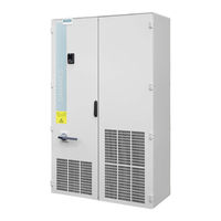
Siemens SINAMICS G120P Operating Instructions Manual (496 pages)
Converter Cabinet Units 110 kW — 400 kW
Brand: Siemens
|
Category: Enclosure
|
Size: 20.67 MB
Table of Contents
-
Preface
5
-
Table of Contents
9
-
1 Safety Information
17
-
General Safety Instructions
17
-
Safety Instructions for Electromagnetic Fields (EMF)
20
-
Handling Electrostatic Sensitive Devices (ESD)
20
-
Residual Risks of Power Drive Systems
21
-
-
2 Device Overview
23
-
Section Content
23
-
Applications, Features
24
-
Field of Applications
24
-
Features, Quality, Service
24
-
Design
25
-
Enclosed Drive Type a
26
-
Enclosed Chassis Type C
27
-
Wiring Principle
28
-
Type Plate
29
-
-
3 Mechanical Installation
33
-
Section Content
33
-
Transport, Storage
33
-
Assembly
36
-
Mechanical Installation: Checklist
36
-
Preparation
37
-
Requirements for Installation Location
37
-
Requirements on the Levelness of the Floor
38
-
Shipping and Handling Indicators
39
-
Unpacking
41
-
Required Tools
41
-
Installation
42
-
Lifting the Cabinet off the Transport Pallet
42
-
Disassembling the Crane Transport Assembly
44
-
Connection to the Foundation
45
-
Assembly of the Air Deflectors for IP20 Degree of Protection and Type a
46
-
Fitting Additional Canopies (Option M21) or Hoods (Option M23, M43, M54)
47
-
-
4 Electrical Installation
51
-
Section Content
51
-
Checklist for Electrical Installation
52
-
Important Safety Precautions
56
-
Introduction to EMC
57
-
EMC Compliant Design
59
-
Power Connections
61
-
Cable Lugs
62
-
Connection Cross-Sections, Cable Lengths
63
-
Connecting the Motor and Power Cables
64
-
Open the Connection Clip to the Basic Interference Suppression Module for Operation on an Ungrounded Line Supply (IT System)
67
-
External Supply of the Auxiliary Supply from a Secure Line
70
-
230 VAC Auxiliary Supply
71
-
24 VDC Auxiliary Supply
71
-
Signal Connections
71
-
CU230P-2 Control Unit
71
-
CU230P-2 PN Control Unit (Option K96)
72
-
CU230P-2 DP Control Unit (Option K97)
78
-
CU230P-2 HVAC Control Unit (Option K98)
87
-
CU230P-2 CAN Control Unit (Option K99)
93
-
Terminal Block -X9
99
-
Other Connections
103
-
Auxiliary Power Supply, 230 VAC (Option K74)
104
-
Clean Power Version with Integrated Line Harmonics Filter (Option L01)
105
-
DV/Dt Filter Compact Plus Voltage Peak Limiter (Option L07)
106
-
DV/Dt Filter Plus Voltage Peak Limiter (Option L10)
108
-
Connection for External Auxiliary Equipment (Option L19)
109
-
EMERGENCY off Button Installed in the Cabinet Door (Option L45)
111
-
Cabinet Lighting with Service Socket (Option L50)
112
-
Cabinet Anti-Condensation Heating (Option L55)
113
-
EMERGENCY STOP Category 0; 24 VDC (Option L57)
114
-
EMERGENCY STOP Category 1; 24 VDC (Option L60)
115
-
Braking Unit 50 Kw (Option L62)
116
-
Commissioning
119
-
Diagnosis and Duty Cycles
119
-
Threshold Switch
120
-
Thermistor Motor Protection Device (Option L83/L84)
121
-
PT100 Evaluation Unit (Option L86)
122
-
-
5 Commissioning
123
-
Section Content
123
-
Pre-Assignment of Inputs/Outputs and Wiring Via P0015 Macros
124
-
Commissioning with the IOP
128
-
The IOP Operator Panel
128
-
Initial Setting
131
-
Basic Commissioning with IOP
136
-
STARTER Commissioning Tool
142
-
Installing STARTER
143
-
Explanations Regarding the STARTER User Interface
144
-
Procedure for Commissioning Via STARTER
145
-
Creating the Project
145
-
Configure the Drive Unit
152
-
Commissioning the Drive Unit
158
-
-
6 Operation
169
-
Section Content
169
-
Basic Information about the Drive System
170
-
Parameters
170
-
Data Sets
171
-
BICO Technology: Interconnecting Signals
174
-
Communication Via PROFINET
178
-
What Do You Need for Communication Via PROFINET
178
-
Connect the Converter to PROFINET
179
-
Configuring Communication to the Control
179
-
Select Telegram
180
-
Activating Diagnostics Via the Control
181
-
Identification & Maintenance Data (I&M)
181
-
Communication Via PROFIBUS
182
-
What Do You Need for Communication Via PROFIBUS
182
-
Connect the Frequency Inverter to PROFIBUS
183
-
Configuring Communication to the Control
183
-
Setting the Address
184
-
Select Telegram
185
-
Profidrive Profile for PROFIBUS and PROFINET
186
-
Cyclic Communication
186
-
Control and Status Word 1
188
-
Control and Status Word 3
191
-
Extend Telegrams and Change Signal Interconnection
192
-
Data Structure of the Parameter Channel
194
-
Slave-To-Slave Communication
199
-
Acyclic Communication
200
-
Profienergy Profile for PROFINET
204
-
Communication Via Ethernet/Ip
207
-
Connect Converter to Ethernet/Ip
207
-
What Do You Need for Communication Via Ethernet/Ip
208
-
Communication Settings for Ethernet/Ip
208
-
Additional Settings if You Are Working with the ODVA AC/DC Drive Profile
209
-
Supported Objects
210
-
Create Generic I/O Module
216
-
Communication Via RS485
217
-
Integrating Inverters into a Bus System Via the RS485 Interface
217
-
Communication Via USS
218
-
Basic Settings for Communication
218
-
Telegram Structure
220
-
User Data Range of the USS Telegram
221
-
USS Parameter Channel (PIV)
222
-
USS Process Data Channel (PZD)
227
-
Time-Out and Other Errors
227
-
Communication over Modbus RTU
230
-
Basic Settings for Communication
231
-
Modbus RTU Telegram
233
-
Baud Rates and Mapping Tables
233
-
Write and Read Access Via FC 03 and FC 06
237
-
Communication Procedure
239
-
Communication Via Bacnet MS/TP
241
-
Basic Settings for Communication
242
-
Supported Services and Objects
244
-
Communication Via P1
252
-
Communication over Canopen
257
-
Canopen Functions of the Converter
257
-
Network Management (NMT Service)
258
-
SDO Services
261
-
Access to SINAMICS Parameters Via SDO
262
-
Access PZD Objects Via SDO
264
-
PDO and PDO Services
266
-
Predefined Connection Set
270
-
Free PDO Mapping
271
-
Interconnect Objects from the Receive and Transmit Buffers
274
-
Canopen Operating Modes
276
-
Object Directories
276
-
General Objects from the Cia 301 Communication Profile
276
-
Free Objects
286
-
Objects from the Cia 402 Drive Profile
286
-
Integrating the Converter into Canopen
288
-
Connecting Inverter to CAN Bus
289
-
Setting the Node ID and Baud Rate
289
-
Setting the Monitoring of the Communication
290
-
Free PDO Mapping for Example of the Actual Current Value and Torque Limit
292
-
Operation with the IOP
294
-
Overview
294
-
Introduction
294
-
Screen Icons
294
-
Menu Structure
296
-
Wizards
297
-
Wiring Diagrams
304
-
Control
308
-
Menu
311
-
Overview
311
-
Diagnostics
312
-
Parameters
316
-
Up/Download
321
-
Extras
322
-
Write Protection
333
-
Siemens SINAMICS G120P Operating Instructions Manual (462 pages)
low voltage converters, chassis and wall/panel mounted devices with CU230P-2 control units
Brand: Siemens
|
Category: Media Converter
|
Size: 32.63 MB
Table of Contents
-
Legal Information
4
-
Changes in this Manual
5
-
Converter with CU230P-2 Control Units Operating Instructions, 04/2015, FW V4.7 SP3, A5E34257946B AB
5
-
Table of Contents
7
-
-
1 Fundamental Safety Instructions
13
-
General Safety Instructions
13
-
Safety Instructions for Electromagnetic Fields (EMF)
17
-
Handling Electrostatic Sensitive Devices (ESD)
17
-
Industrial Security
18
-
Residual Risks of Power Drive Systems
19
-
-
2 Introduction
21
-
About the Manual
21
-
Guide through the Manual
22
-
-
3 Description
25
-
Identifying the Converter
25
-
Control Units
27
-
Power Module
28
-
Power Modules in Degree of Protection IP20 and with Push-Through System
28
-
Power Module in IP55 Degree of Protection / UL Type 12
31
-
Components for the Power Modules
32
-
Accessories for Installation and Shielding
32
-
Line Filter
33
-
Line Reactor
34
-
Output Reactor
37
-
Sine-Wave Filter
41
-
DV/Dt Filter
42
-
Braking Module and Braking Resistor
42
-
Motor Series that Are Supported
45
-
Tools to Commission the Converter
46
-
-
4 Installing
47
-
Overview of the Inverter Installation
47
-
Connecting Inverters in Compliance with EMC
48
-
EMC-Compliant Connection of the Converter
48
-
Avoiding Electromagnetic Influence (EMI)
48
-
Amount the Shield Plate Onto the Power Module
51
-
Installing Reactors, Filters and Braking Resistors
54
-
Installing Power Modules
56
-
Dimensions, Hole Drilling Templates, Minimum Clearances, Tightening Torques
58
-
Digital Inputs and Outputs on the PM330 Power Module
66
-
Connecting the Line Supply, Motor and Converter Components
69
-
Permissible Line Supplies
69
-
Connecting the Inverter
73
-
Connecting a Braking Resistor
77
-
Installing Control Unit
79
-
Overview of the Interfaces
82
-
Fieldbus Interface Allocation
83
-
Terminal Strips
84
-
Factory Setting of the Interfaces
86
-
Default Setting of the Interfaces
88
-
Wiring Terminal Strips
106
-
Connecting the Inverter to the Fieldbus
107
-
Profinet
108
-
Profibus
112
-
-
5 Commissioning
115
-
Commissioning Guidelines
115
-
Preparing for Commissioning
116
-
Collecting Motor Data
116
-
Factory Setting of the Converter Control
116
-
Defining Additional Requirements for the Application
118
-
Commissioning Using a BOP-2 Operator Panel
119
-
Starting Basic Commissioning
119
-
Basic Commissioning with Application Classes
127
-
Starting Basic Commissioning
127
-
Standard Drive Control
129
-
Dynamic Drive Control
131
-
Commissioning with a PC
135
-
Creating a Project
136
-
Transfer Inverters Connected Via USB into the Project
136
-
Go Online and Start the Configuration Wizards
139
-
Standard Drive Control
141
-
Dynamic Drive Control
142
-
Configuration for Experts
143
-
Identify Motor Data
146
-
Restoring the Factory Setting
148
-
-
6 Advanced Commissioning
151
-
Overview of the Inverter Functions
151
-
Inverter Control
153
-
Switching the Motor on and off
153
-
Adapt the Default Setting of the Terminal Strip
155
-
Digital Inputs
156
-
Digital Outputs
158
-
Analog Inputs
159
-
Analog Outputs
163
-
Inverter Control Using Digital Inputs
166
-
Two-Wire Control: Method 1
167
-
Two-Wire Control, Method 2
168
-
Two-Wire Control, Method 3
169
-
Three-Wire Control, Method 1
170
-
Three-Wire Control, Method 2
171
-
Running the Motor in Jog Mode (JOG Function)
172
-
Control Via PROFIBUS or PROFINET with the Profidrive Profile
173
-
Control and Status Word 1
175
-
Control and Status Word 3
178
-
NAMUR Message Word
180
-
Data Structure of the Parameter Channel
180
-
Examples of the Parameter Channel
184
-
Extend Telegrams and Change Signal Interconnection
185
-
Configuring the IP Interface
187
-
Slave-To-Slave Communication
187
-
Acyclically Reading and Writing Inverter Parameters
188
-
Control Via Additional Fieldbuses
189
-
Modbus RTU
189
-
Uss
192
-
Canopen
195
-
Bacnet MS/TP
196
-
Ethernet/Ip
199
-
Switching over the Inverter Control (Command Data Set)
201
-
Setpoints
203
-
Analog Input as Setpoint Source
204
-
Specifying the Setpoint Via the Fieldbus
205
-
Motorized Potentiometer as Setpoint Source
206
-
Fixed Speed as Setpoint Source
208
-
Setpoint Calculation
211
-
Overview of Setpoint Processing
211
-
Invert Setpoint
212
-
Enable Direction of Rotation
213
-
Skip Frequency Bands and Minimum Speed
214
-
Speed Limitation
215
-
Ramp-Function Generator
216
-
Motor Control
219
-
V/F Control
219
-
Characteristics of U/F Control
221
-
Optimizing Motor Starting
224
-
Vector Control with Speed Controller
227
-
Overview
227
-
Optimizing the Speed Controller
229
-
Protection Functions
231
-
Inverter Temperature Monitoring
231
-
Motor Temperature Monitoring Using a Temperature Sensor
234
-
Protecting the Motor by Calculating the Motor Temperature
236
-
Overcurrent Protection
238
-
Limiting the Maximum DC Link Voltage
239
-
Application-Specific Functions
241
-
Unit Changeover
241
-
Changing over the Motor Standard
242
-
Changing over the Unit System
243
-
Changing over Process Variables for the Technology Controller
243
-
Switching Units with STARTER
244
-
Calculating the Energy Saving
246
-
Electrically Braking the Motor
248
-
DC Braking
249
-
Compound Braking
252
-
Dynamic Braking
254
-
Braking with Regenerative Feedback to the Line
255
-
Flying Restart — Switching on While the Motor Is Running
256
-
Automatic Switch-On
258
-
Kinetic Buffering (VDC Min Control)
262
-
Line Contactor Control
264
-
PID Technology Controller
266
-
Free Technology Controllers
271
-
System Protection
273
-
No-Load Monitoring, Blocking Protection, Stall Protection
274
-
Load Monitoring
276
-
Real Time Clock (RTC)
281
-
Time Switch (DTC)
283
-
Essential Service Mode
284
-
Multi-Zone Control
288
-
Bypass
291
-
Cascade Control and Hibernation Mode
296
-
Cascade Control
296
-
Hibernation Mode
300
-
Free Function Blocks
305
-
Further Information
305
-
Switchover between Different Settings
306
-
Advertisement
Siemens SINAMICS G120P Function Manual (244 pages)
Fieldbuses
Brand: Siemens
|
Category: Inverter
|
Size: 11.77 MB
Table of Contents
-
Table of Contents
5
-
1 Fundamental Safety Instructions
9
-
General Safety Instructions
9
-
Industrial Security
10
-
-
2 Introduction
11
-
Ethernet and PROFINET Protocols that Are Used
12
-
-
3 Communication Via PROFIBUS and PROFINET
15
-
Profidrive Profile
15
-
Cyclic Communication
15
-
Assigning Control and Status Words
19
-
NAMUR Message Word
27
-
Control and Status Word, Encoder
28
-
Position Actual Value of the Encoder
30
-
Extend Telegrams and Change Signal Interconnection
32
-
Data Structure of the Parameter Channel
33
-
Slave-To-Slave Communication
39
-
Acyclic Communication
40
-
Diagnostics Channels
45
-
Diagnostics with PROFINET
46
-
Diagnostics with PROFIBUS
47
-
Identification & Maintenance Data (I&M)
51
-
S7 Communication
52
-
Directly Accessing a SINAMICS G120 Converter from a SIMATIC Panel
52
-
Communication Via PROFINET
56
-
Inverter with PROFINET Interface
58
-
Integrating Inverters into PROFINET
59
-
PROFINET IO Operation
60
-
What Do You Need for Communication Via PROFINET
60
-
Configuring Communication to the Control
60
-
Installing GSDML
62
-
Activating Diagnostics Via the Control
62
-
Profienergy
62
-
General Inverter Behavior When in the Profienergy Energy-Saving Mode
63
-
Supported Profienergy Energy-Saving Modes
63
-
Settings and Displays for Profienergy in the Inverter
64
-
Control Commands and Status Queries
65
-
The Inverter as Ethernet Node
67
-
Communication Via PROFIBUS
69
-
Inverters with PROFIBUS Interface
70
-
What Do You Need for Communication Via PROFIBUS
72
-
Integrating Inverters into PROFIBUS
72
-
Configuring Communication to the Control System
73
-
Configuring the Communication Using SIMATIC S7 Control
73
-
Configuring the Communication with a Third-Party Control System
73
-
Installing the GSD
73
-
Setting the Address
74
-
Select Telegram
75
-
-
4 Communication Via Ethernet/Ip
77
-
Inverters with Ethernet/Ip Interface
78
-
Connect Converter to Ethernet/Ip
80
-
What Do You Need for Communication Via Ethernet/Ip
80
-
Configuring Communication Via Ethernet/Ip
81
-
Communication Settings
81
-
Special Issues if You Wish to Use the ODVA AC/DC Drive Profile
82
-
Supported Objects
83
-
Supported ODVA AC/DC Assemblies
98
-
Create Generic I/O Module
99
-
The Inverter as an Ethernet Station
100
-
Siemens SINAMICS G120P Function Manual (244 pages)
Fieldbus systems
Brand: Siemens
|
Category: Media Converter
|
Size: 8.2 MB
Table of Contents
-
Legal Information
4
-
Preface
5
-
Table of Contents
7
-
1 Fundamental Safety Instructions
11
-
General Safety Instructions
11
-
Warranty and Liability for Application Examples
11
-
Industrial Security
12
-
-
2 General Information
15
-
Ethernet and PROFINET Protocols that Are Used
16
-
-
3 Communication Via PROFIBUS and PROFINET
19
-
PROFIDRIVE Profile — Cyclic Communication
19
-
Assigning Control and Status Words
23
-
Control and Status Word 1
23
-
Control and Status Word 2
27
-
Control and Status Word 3
28
-
NAMUR Message Word
30
-
Control and Status Word, Encoder
31
-
Position Actual Value of the Encoder
33
-
Extend Telegrams and Change Signal Interconnection
35
-
Data Structure of the Parameter Channel
37
-
Application Examples
41
-
Slave-To-Slave Communication
43
-
PROFIDRIVE Profile — Acyclic Communication
44
-
Profidrive Profile — Diagnostic Channels
49
-
Diagnostics with PROFINET
50
-
Diagnostics with PROFIBUS
52
-
Identification & Maintenance Data (I&M)
56
-
S7 Communication
57
-
Directly Accessing a SINAMICS G120 Converter from a SIMATIC Panel
57
-
Communication Via PROFINET
61
-
Converter with PROFINET Interface
63
-
Integrating Inverters into PROFINET
64
-
PROFINET IO Operation
65
-
What Do You Have to Set for Communication Via PROFINET
65
-
Configuring Communication to the Control
65
-
Installing GSDML
67
-
Activating Diagnostics Via the Control
67
-
Profienergy
67
-
General Inverter Behavior When in the Profienergy Energy-Saving Mode
68
-
Supported Profienergy Energy-Saving Modes
68
-
Settings and Displays for Profienergy in the Inverter
69
-
Control Commands and Status Queries
70
-
The Inverter with PROFINET Interface as Ethernet Node
72
-
Communication Via PROFIBUS
74
-
Inverters with PROFIBUS Interface
75
-
What Do You Have to Set for Communication Via PROFIBUS
77
-
Integrating Inverters into PROFIBUS
78
-
Configuring Communication to the Control System
78
-
Configuring the Communication Using SIMATIC S7 Control
78
-
Configuring the Communication with a Third-Party Control System
78
-
Installing the GSD
79
-
Setting the Address
80
-
Select Telegram
81
-
-
4 Communication Via Ethernet/Ip
83
-
Inverters with Ethernet/Ip Interface
84
-
Connect Converter to Ethernet/Ip
86
-
What Do You Need for Communication Via Ethernet/Ip
87
-
Configuring Communication Via Ethernet/Ip
88
-
Communication Settings
88
-
Special Issues if You Wish to Use the ODVA AC/DC Drive Profile
89
-
Supported Objects
90
-
Supported ODVA AC/DC Assemblies
104
-
Create Generic I/O Module
105
-
The Inverter as an Ethernet Station
106
-
Siemens SINAMICS G120P Technical Manual (98 pages)
Variable Speed Drive
Brand: Siemens
|
Category: Inverter
|
Size: 6.43 MB
Table of Contents
-
Table of Contents
3
-
1 History of Changes
5
-
2 About this Documentation
6
-
Purpose of this Documentation
6
-
Product Documentation
8
-
Download Center
9
-
-
3 Safety
10
-
Intended Use
10
-
Safety Equipment
11
-
Personnel Requirements
11
-
Responsibilities of the Operating Personnel
12
-
Residual Risks
12
-
Voltage Hazards
13
-
Dangers Posed by Moving Parts
14
-
Dangers Due to Fire and Explosion
15
-
Dangers Due to Electromagnetic Fields
16
-
Dangers Due to Parameterization Errors
16
-
Dangers Due to Inactive Safety Functions
16
-
Dangers Due to Unsuitable Site of Installation
17
-
-
Handling Electrostatic Discharge Sensitive Devices
17
-
Disclaimer of Liability
18
-
-
4 Product Information
19
-
Product Description
19
-
Components
20
-
CU230P-2-BT Control Unit
21
-
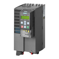
PM230 Power Module
23
-
Operator Panels
24
-
-
License Terms
27
-
-
5 Installing
28
-
Safety Instructions for Installation
28
-
Overview of Installation
29
-
Installing the Power Module
30
-
Installing Power Modules
30
-
Connecting Line and Motor Terminals
31
-
-
Installing the Control Unit
40
-
Wiring Terminal Strips
42
-
-
Installing the Operator Panel
44
-
EMC-Compliant Installation (Examples)
45
-
-
6 Commissioning
50
-
Safety Instructions for Commissioning
50
-
Overview of the Commissioning
50
-
Preparing for Commissioning
51
-
Carrying out Basic Commissioning
51
-
Configuring Communication
55
-
Additional Settings
60
-
Restoring Parameters to Factory Settings
60
-
Setting the PID Controller
60
-
Overview of Parameters
61
-
-
Backing up Data (Memory Card)
65
-
Siemens SINAMICS G120P Hardware Installation Manual (94 pages)
Power Module PM230 IP55/UL Type 12
Brand: Siemens
|
Category: Inverter
|
Size: 5.18 MB
Table of Contents
-
Table of Contents
5
-
1 Introduction
7
-
System Overview of the SINAMICS G120P
7
-
Documents for the Inverter
12
-
-
2 Safety Notes
13
-
3 Installing / Mounting
19
-
Air Cooling Requirements
21
-
Dimensions and Drill Patterns
22
-
Control Unit Installation
29
-
Fitting the IOP and the Blanking Plate
34
-
-
4 Connecting
37
-
Power Distribution Systems
38
-
Operation Only with Grounded (TN) Supplies
38
-
Motor Cable Lengths and Cross-Sections
39
-
Access to Power and Motor Terminals
43
-
Cable Preparation
46
-
Wiring Sequence
47
-
Power and Motor Connections
50
-
Gland Plate Installation
51
-
EMC Guidelines
54
-
Avoiding Electromagnetic Interference
54
-
Connections and Interference Suppression
54
-
Cabling
54
-
Equipotential Bonding
55
-
Inverter Shielding in Detail, FSA to FSC
58
-
-
5 Service and Maintenance
61
-
Maintenance
61
-
Cleaning
61
-
Replacing Components
62
-
Replacing the Cooling Fan
62
-
Replacement Fans
69
-
Spares and Accessories
71
-
-
6 Technical Specifications
73
-
General Data, PM230, IP55
74
-
Temperature, Altitude and Voltage Derating PM230
75
-
Technical Data
77
-
Input Current Operation
77
-
Current Reduction Depending on Pulse Frequency
82
-
-
7 Appendix
83
-
Electromagnetic Compatibility
83
-
Definition of the EMC Environment and Categories
84
-
EMC Overall Performance
86
-
Standards
88
-
Abbreviations
89
-
Index
91
-
Siemens SINAMICS G120P Manual (60 pages)
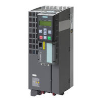
Variable Speed Drive
Brand: Siemens
|
Category: Inverter
|
Size: 1.87 MB
Table of Contents
-
Table of Contents
3
-
1 Safety
5
-
Typographical Conventions
5
-
Disclaimer of Liability
7
-
-
2 Mounting and Installation
8
-
Dimension Drawings of the PM230
8
-
Structure of the Control Unit
8
-
Terminal Strips in the Control Unit
9
-
Motor Cable Lengths and Cross-Sections
9
-
Cable Specifications for Conformity with EMC Requirements
9
-
Cable Cross-Sections
10
-
-
Wiring Sequence for IP55
10
-
Line and Motor Connections
12
-
Ip55
12
-
Ip20
14
-
-
EMC Directives
15
-
Ip55
16
-
Ip20
18
-
-
-
3 Commissioning
20
-
Operator Panels
20
-
Iop
20
-
Bop-2
22
-
Saving Drive Data on a ROM
22
-
-
Preparing for Commissioning
23
-
Basic Factory Settings
23
-
Basic Commissioning with the Wizard
24
-
Iop
25
-
Bop-2
25
-
-
Additional Settings
26
-
Resetting to Factory Settings
26
-
Setting the Ramp-Function Generator
27
-
Setting the PID Controller
28
-
Transferring the License Terms
28
-
-
Additional Important Parameters
29
-
Communication
30
-
RS485 Interface
31
-
USS Protocol
32
-
Modbus RTU Protocol
33
-
Bacnet MS/TP
33
-
Basic Settings
34
-
P1 Fln
35
-
-
Data Backup on a Memory Card
36
-
-
4 Application Examples
37
-
Universal Application
37
-
Pump Pressure Control
38
-
Pressure Controlled Supply Fan + ESM Fixed Speed
39
-
Cooling Tower Fan (LG-Ni1000) + Hibernation
40
-
Cooling Tower Fan (Active Sensor) + Hibernation
41
-
Stairwell Pressurization (ESM)
42
-
Fixed Setpoints
43
-
CO2 Sensor, 2 PID Setpoints
44
-
Temperature-Dependent Pressure Setpoint
45
-
Siemens SINAMICS G120P Instruction Manual (100 pages)
Brand: Siemens
|
Category: Inverter
|
Size: 3.89 MB
Table of Contents
-
Safety Instructions
5
-
Table of Contents
7
-
Power Module
12
-
Control Unit
13
-
Wiring the Control Terminals in the CU230P-2
32
-
Operator Panels BOP-2 and IOP
38
-
Menu Structure
39
-
Working with BOP
40
-
Parameter List
41
-
-
Control Unit
42
-
-
Resetting the Converter
44
-
Entering Motor Data
46
-
Specifying Application Parameters
47
-
Saving and Restoring Data
50
-
-
The Device
52
-
Basic Commissioning
54
-
Output Settings
62
-
Trend View
64
-
-
Creating a STARTER Project
74
-
STARTER User Interface
77
-
Loading Converter Data
78
-
-
Configuration Wizard
82
-
Wiring Example
86
-
Activating Emergency Operation
87
-
Saving Data
91
-
Restoring Factory Settings
94
-
Siemens SINAMICS G120P Hardware Installation Manual (66 pages)
Power Module PM230, IP20 / Push through
Brand: Siemens
|
Category: DC Drives
|
Size: 2.8 MB
Table of Contents
-
Table of Contents
5
-
1 Introduction
7
-
2 Safety Notes
9
-
3 Installing/Mounting
13
-
Installation Conditions
13
-
Power Losses and Air Cooling Requirements
14
-
Mounting the Power Modules
16
-
Build-In Power Modules — IP20
16
-
Push-Through Power Modules — IP54
19
-
Control Unit Installation
22
-
-
4 Connecting
23
-
Mains and Motor Connection
24
-
Motor Cable Length
25
-
Motor Connection
25
-
Mains and Motor Terminals, FSA
26
-
Mains and Motor Terminals, FSD
26
-
EMC Compliant Connection
27
-
Avoiding Electromagnetic Interference
27
-
EMC-Compliant Cabinet Design
27
-
Cabinet Design
28
-
Cabling
29
-
Equipotential Bonding
31
-
EMC-Compliant Wiring
34
-
-
5 Service and Maintenance
37
-
Maintenance
37
-
Replacing the Cooling Fan
38
-
-
6 Technical Specifications
41
-
Specifications
44
-
Derating Data
50
-
Operational Temperature and Temperature Derating
50
-
Operational Altitude and Altitude Deratings
50
-
Operational Power and Voltage Derating
51
-
Current Reduction Depending on Pulse Frequency
51
-
Permissible Shock and Vibration Values
52
-
-
7 Accessories
53
-
Mounting Frames
53
-
-
Appendix
55
-
Further Information on Your Converter
55
-
Manuals for Your Inverter
55
-
Configuring Support
56
-
Product Support
56
-
Electromagnetic Compatibility
57
-
Definition of the EMC Environment and Categories
57
-
Compliance with EMC Environment and Categories
58
-
EMC Limit Values in South Korea
59
-
Standards
60
-
Abbreviations
61
-
Index
63
-
Siemens SINAMICS G120P Manual (62 pages)
Speed Control of a Startdrive with TIA Portal via PROFIBUS DP with Safety Integrated (via Terminal) and HMI
Brand: Siemens
|
Category: Control Unit
|
Size: 3.83 MB
Table of Contents
-
Legal Information
2
-
Table of Contents
3
-
-
1 Task
4
-
2 Solution
5
-
Solution Overview
5
-
Description of the Core Functionality
6
-
Configuring the Communication
6
-
Data Exchange
6
-
Hardware and Software Components Used
7
-
-
3 Setting up and Commissioning the Application
9
-
Wiring
9
-
IP and PB Addresses
10
-
PG/PC Settings
10
-
Setting the PROFIBUS Address at the G120 DP
11
-
Loading the Software
11
-
-
4 Operating the Application
19
-
Preconditions
19
-
Operation Via Digital Inputs
20
-
Monitoring and Parameter Access Via Operator Panel
21
-
Screens and Screen Navigation
21
-
Process Data Exchange
22
-
Parameter Access
25
-
Operator Control and Monitoring Via Monitoring Table
27
-
-
5 Functional Mechanisms of this Application
29
-
Functionality of Process Data Exchange
30
-
Accessing Process Data in the User Program of the Controller
30
-
Standardizing the Setpoint and Actual Values
31
-
Transfer Method
31
-
Control Word (STW1) and Status Word (ZSW1)
32
-
FB 11 «Process_Data
34
-
Parameter Access Functionality
38
-
Job and Response Structure
38
-
The Dbs «Read/Write_Drive_Parameters» and «Answer_From_Drive
39
-
FB 20 «Parameters
41
-
-
6 Configuration and Settings
45
-
Creating the Project Configuration
45
-
Configuration of the Components
45
-
Change Device of SINAMICS G120
53
-
Safe Torque off (STO) with Safety Integrated
54
-
Comments on Programming the SIMATIC S7-1200
58
-
Configuring the DPRD_DAT/DPWR_DAT Instruction
58
-
Configuring the RDREC/WRREC Instruction
60
-
-
7 Related Literature
61
-
8 History
62
Siemens SINAMICS G120P Operating Instructions Manual (34 pages)
Du/dt filter compact plus Voltage Peak Limiter for Power Modules PM330
Brand: Siemens
|
Category: Media Converter
|
Size: 0.89 MB
Table of Contents
-
Table of Contents
5
-
Safety Information
7
-
Warnings
7
-
Components that Can be Destroyed by Electrostatic Discharge (ESD)
8
-
-
General
11
-
Mechanical Installation
15
-
Electrical Installation
19
-
Maintenance and Servicing
27
-
Technical Specifications
29

Siemens SINAMICS G120P Manual (18 pages)
Pump control with timer
Brand: Siemens
|
Category: Controller
|
Size: 0.83 MB
Table of Contents
-
Legal Information
2
-
Table of Contents
3
-
-
1 Introduction
4
-
Overview
4
-
Principle of Operation
5
-
Components Used
5
-
-
2 Engineering
6
-
Hardware Setup
6
-
Wiring the SINAMICS G120P
6
-
Basic Operator Panel
7
-
Commissioning the Drive
9
-
Step 1: Quick Commissioning
9
-
Step 2: Parameterization of the Mode of Operation
12
-
Operation
13
-
Error Handling
14
-
LED Display
14
-
Warnings
14
-
Faults
14
-
-
3 Useful Information
15
-
Real Time Clock (RTC)
15
-
Temperature Input
16
-
-
4 Appendix
17
-
Service and Support
17
-
Links and Literature
18
-
Change Documentation
18
-
Siemens SINAMICS G120P Operating Instructions Manual (24 pages)
Braking resistors for PM330 Power Modules
Brand: Siemens
|
Category: Industrial Electrical
|
Size: 0.59 MB
Table of Contents
-
Table of Contents
5
-
1 Safety Information
7
-
Warnings
7
-
-
2 General
9
-
3 Mechanical Installation
13
-
General
13
-
Installing the Braking Resistor
14
-
-
4 Electrical Installation
15
-
Cable Lugs
15
-
Connecting the Braking Resistor
16
-
Parameterizing Operation with Braking Resistor
17
-
-
5 Maintenance and Servicing
19
-
6 Technical Specifications
21
Siemens SINAMICS G120P Operating Instructions Manual (28 pages)
du/dt fillter plus voltage peak limiter
Brand: Siemens
|
Category: Control Unit
|
Size: 0.74 MB
Table of Contents
-
Table of Contents
5
-
Safety Information
7
-
Warnings
7
-
Components that Can be Destroyed by Electrostatic Discharge (ESD)
9
-
-
General
11
-
Mechanical Installation
15
-
Electrical Installation
19
-
Maintenance and Servicing
23
-
Technical Specifications
25
Siemens SINAMICS G120P Operating Instructions Manual (26 pages)
filter for PM330 power module
Brand: Siemens
|
Category: Water Filtration Systems
|
Size: 0.59 MB
Table of Contents
-
Table of Contents
5
-
1 Safety Information
7
-
Warnings
7
-
Safety and Application Instructions
8
-
Components that Can be Destroyed by Electrostatic Discharge (ESD)
9
-
-
2 General
11
-
3 Mechanical Installation
15
-
4 Electrical Installation
17
-
5 Maintenance and Servicing
21
-
6 Technical Specifications
23

Siemens SINAMICS G120P Operating Instructions Manual (26 pages)
du/dt filter plus Voltage Peak Limiter for PM330 Power Modules
Brand: Siemens
|
Category: Water Filtration Systems
|
Size: 0.65 MB
Table of Contents
-
Table of Contents
5
-
1 Safety Information
7
-
Warnings
7
-
Safety and Application Instructions
8
-
Components that Can be Destroyed by Electrostatic Discharge (ESD)
9
-
-
2 General
11
-
3 Mechanical Installation
15
-
4 Electrical Installation
17
-
5 Maintenance and Servicing
21
-
6 Technical Specifications
23
Siemens SINAMICS G120P Operating Instructions Manual (22 pages)
Line filter
Brand: Siemens
|
Category: Water Filtration Systems
|
Size: 0.51 MB
Table of Contents
-
Table of Contents
5
-
1 Safety Information
7
-
Warnings
7
-
Safety and Application Instructions
8
-
Components that Can be Destroyed by Electrostatic Discharge (ESD)
9
-
-
2 General
11
-
3 Mechanical Installation
15
-
4 Electrical Installation
17
-
5 Technical Specifications
19

Siemens SINAMICS G120P Operating Instructions Manual (22 pages)
Line filters for PM330 Power Modules
Brand: Siemens
|
Category: DC Drives
|
Size: 0.56 MB
Table of Contents
-
Table of Contents
5
-
Safety Information
7
-
Warnings
7
-
Components that Can be Destroyed by Electrostatic Discharge (ESD)
9
-
-
General
11
-
Mechanical Installation
15
-
Electrical Installation
17
-
Technical Specifications
19

Siemens SINAMICS G120P Operating Instructions Manual (22 pages)
Output reactors
Brand: Siemens
|
Category: Inverter
|
Size: 0.59 MB
Table of Contents
-
Table of Contents
5
-
Safety Information
7
-
Warnings
7
-
-
General
9
-
Mechanical Installation
13
-
Electrical Installation
17
-
Technical Specifications
19

Siemens SINAMICS G120P Operating Instructions Manual (18 pages)
Line reactors for Power Modules PM330
Brand: Siemens
|
Category: Industrial Equipment
|
Size: 0.47 MB
Table of Contents
-
Table of Contents
5
-
Safety Information
7
-
Warnings
7
-
-
General
9
-
Mechanical Installation
11
-
Electrical Installation
13
-
Technical Specifications
15
Advertisement
Related Products
-
Siemens SINAMICS G120P CU230P-2
-
Siemens SINAMICS G120D CU240D-2 DP
-
Siemens SINAMICS G120D CU250D-2 DP-F
-
Siemens Sinamics G120 CU240E
-
Siemens Sinamics G120 CU240S PN-F
-
Siemens Sinamics G120 CU240S DP
-
Siemens Sinamics G120 CU240S PN
-
Siemens SINAMICS G120 CU250S-2 Series
-
Siemens SINAMICS G120 CU230P-2
-
Siemens SINAMICS G120 CU240E-2
Siemens Categories
Controller
Control Unit
Industrial Equipment
![]()
Washer
![]()
Switch
More Siemens Manuals
-
Contents
-
Table of Contents
-
Bookmarks
Quick Links
Variable Speed Drive
G120P
Mounting
Commissioning
CM2G5111en
2014-05-16
Building Technologies
Related Manuals for Siemens G120P
Summary of Contents for Siemens G120P
-
Page 1
Variable Speed Drive G120P Mounting Commissioning Building Technologies CM2G5111en 2014-05-16… -
Page 3: Table Of Contents
RS485 interface…………….31 3.7.2 USS protocol ………………32 3.7.3 Modbus RTU protocol…………… 33 3.7.4 BACnet MS/TP …………….. 33 3.7.5 P1 FLN ………………… 35 Data backup on a memory card…………… 36 Application examples………………37 Universal application ………………37 Siemens AG CM2G5111en 2014-05-16…
-
Page 4
Displayed operating states …………….47 Alarms and faults………………… 48 Hardware diagnostics ………………53 6.4.1 Tests without a power supply …………53 6.4.2 Power test ………………55 6.4.3 Function test………………56 Appendix ………………….58 Commissioning report………………58 Available documentation……………… 58 Siemens AG CM2G5111en 2014-05-16… -
Page 5: Safety
1. Please read this information carefully. 2. Pay attention to all the warning signs which are affixed to the equipment. The warning labels must always be legible. Missing or damaged labels must be replaced. Siemens AG CM2G5111en 2014-05-16…
-
Page 6
● They have to be familiar with all the safety information, installation and operating instructions contained in this Guide and be trained to perform first aid. Siemens AG CM2G5111en 2014-05-16… -
Page 7: Disclaimer Of Liability
Only activate fire or emergency mode if the continuous operation of the drive (fan) is absolutely necessary, e.g., in order to ensure that smoke and heat are extracted in the event of the building being evacuated. Siemens AG CM2G5111en 2014-05-16…
-
Page 8: Mounting And Installation
DGND, reference potential for data Cable shield Not assigned Not connected (C/C’) Not assigned (GND), optional ground VP, supply voltage CAN_H, CAN signal (dominant high) Not assigned RxD/TxD-N, receive and send (A/A’) Not assigned Not assigned Not assigned Siemens AG CM2G5111en 2014-05-16…
-
Page 9: Terminal Strips In The Control Unit
DI = low if the switch is closed Motor cable lengths and cross-sections 2.4.1 Cable specifications for conformity with EMC requirements PM230 Cable type EMC category Max. cable length Filter A Shielded 25 m (80 ft) Siemens AG CM2G5111en 2014-05-16…
-
Page 10: Cable Cross-Sections
, the protective grounding conductor must have at least half of the size of the cross-section of the power cable. Wiring sequence for IP55 The requirements and actions for wiring the Power Module correctly are described below. Siemens AG CM2G5111en 2014-05-16…
-
Page 11
2. Fasten the cable glands to the cables. 3. Ensure that the screws on the cable glands are loosened so that the cables slide through unhindered. See Cable cross-sections [➙ 10]. 4. Attach the ferrite core and shielding Siemens AG CM2G5111en 2014-05-16… -
Page 12: Line And Motor Connections
60 mm 0.39 inches 2.36 inches 0.39 inches 2.36 inches FSB power cables 10 mm 60 mm 50 mm 0.39 inches 2.36 inches 1.96 inches FSB motor cables 10 mm 50 mm 10 mm 40 mm Siemens AG CM2G5111en 2014-05-16…
-
Page 13
Power Module of frame sizes FSD to FSF. The tightening torques for the terminals are indicated in the diagram. Connection of supply voltage Motor connection FSD: M6: 6 Nm (53.0 lbf.in) FSE: M6: 6 Nm (5.3 lbf.in) FSF: M8: 13 Nm (115 lbf.in) Siemens AG CM2G5111en 2014-05-16… -
Page 14: Ip20
Accessing line and motor terminals 1. Loosen the safety catch on the sides of the terminal covers using a suitable size of flat-head screwdriver. 2. Turn the terminal cover up and allow it to engage. Siemens AG CM2G5111en 2014-05-16…
-
Page 15: Emc Directives
Lay the shields over as large a surface as possible at either end, with optimized electrical conductivity to the grounded enclosure. This is the only way of reducing inductive or capacitive interference or stray radiation to a minimum. Siemens AG CM2G5111en 2014-05-16…
-
Page 16: Ip55
This ensures that both the gland plate and the enclosure are in contact with the shield. Feed the motor cable through the right-hand opening on the gland plate, in particular in the case of Power Modules of frame size C and with filter class Siemens AG CM2G5111en 2014-05-16…
-
Page 17
Ferrite rings for line cables Attach the gray ferrite rings between the terminals and the shielding plate on the line cable. The gray ferrite rings are included in the scope of supply for the product. Siemens AG CM2G5111en 2014-05-16… -
Page 18: Ip20
Connect them, in turn, to the control cabinet frame and, in particular, to the PE bar and EMC shield bar over a large area and with good conductivity Follow the instructions in section EMC directives [➙ 15] «Connections and interference suppression» Siemens AG CM2G5111en 2014-05-16…
-
Page 19
2. Shielding without a shield plate EMC-compliant shielding can also be implemented without using a shield plate. In this case, you must ensure that the cable shields are connected to the ground potential over a large area. Siemens AG CM2G5111en 2014-05-16… -
Page 20: Commissioning
AUTO means: The drive responds to external control commands (e.g. fieldbus or terminals) When you toggle to MANUAL mode, the motor continues running at the last setpoint speed selected. When you toggle to AUTO mode, the motor stops. Siemens AG CM2G5111en 2014-05-16…
-
Page 21
In MANUAL mode: pressing starts the drive In AUTO mode: no function In MANUAL mode: – Pressing briefly: OFF1 — the motor comes to a standstill along the set down ramp (parameter P1121) Siemens AG CM2G5111en 2014-05-16… -
Page 22: Bop-2
STARTER commissioning software or if the IOP is in «Save to RAM» mode. IOP 1. Select Options > Save RAM to ROM. 2. Confirm with OK. BOP-2 1. Select Options > RAM to ROM. Siemens AG CM2G5111en 2014-05-16…
-
Page 23: Preparing For Commissioning
ON / OFF AO0- Reverse Output current AO1+ (0..20mA) Acknowledge AO1- Fault DI COM Alarm Control AI0+ Setpoint 0 — 10 V System AI0- Operation Figure 1: Terminal assignment in the factory settings (corresponds to MacPar15 = 12) Siemens AG CM2G5111en 2014-05-16…
-
Page 24: Basic Commissioning With The Wizard
The data is applied automatically. ● If you are not using a Siemens motor, read the data from the motor’s rating plate and enter the appropriate parameters manually. Example: Rating plate details and their assignment to the drive parameters:…
-
Page 25: Iop
STILL: Identify motor data at standstill. The motor does not rotate. We recommend the setting STILL ROT if the motor can rotate freely and if the P1300 control type is set to vector control. In the case of Siemens AG CM2G5111en 2014-05-16…
-
Page 26: Additional Settings
This function restores the drive to factory settings. The communication settings and the settings of the motor standard (IEC/NEMA) are retained after resetting. STARTER 1. Go online with STARTER. 2. Click on the button. IOP Siemens AG CM2G5111en 2014-05-16…
-
Page 27: Setting The Ramp-Function Generator
Acceleration time [p1120] — factory setting 10 s Deceleration time [p1121] — factory setting 10 s Recommended ramp times 0.37 – 3kW 30 s 4 – 15 kW 18.5 – 30 kW 37 – 90 kW 120s Siemens AG CM2G5111en 2014-05-16…
-
Page 28: Setting The Pid Controller
«Read_OSS.ZIP» file onto the memory card. 5. Switch off the drive power supply. 6. Remove the card from the drive. 7. Use a card reader and load the file to a PC. Siemens AG CM2G5111en 2014-05-16…
-
Page 29: Additional Important Parameters
Invert direction of rotation p1200 Flying restart selection: 0: Flying restart inactive 1: Flying restart always active (start in setpoint direction) 4: Flying restart always active (start only in setpoint direction) p1210 Automatic restart: 0: Disables automatic restart Siemens AG CM2G5111en 2014-05-16…
-
Page 30: Communication
[2] = Seconds (0 … 59) p8401 1.1.1970 Date of real-time clock: [0] = Day (1 … 31) [1] = Month (1 … 12) [2] = Year (YYYY) Communication Perform basic commissioning first of all. Siemens AG CM2G5111en 2014-05-16…
-
Page 31: Rs485 Interface
The «Unit switchover» function is not permissible with this bus system. 3.7.1 RS485 interface Integration into Desigo See Engineering Manual TX G120P (document ID: CM110576xx_01). Interfacing to a network 1. Connect the drive to your fieldbus via the RS485 interface. This connector has short-circuit proof, isolated pins.
-
Page 32: Uss Protocol
Fieldbus interface, monitoring time [ms] Setting the time to monitor the process data received via fieldbus. If no process data is received within this time, an appropriate message is output The setting 0 ms deactivates the monitoring. Siemens AG CM2G5111en 2014-05-16…
-
Page 33: Modbus Rtu Protocol
In BACnet, components and systems are considered to be black boxes which contain a number of objects. BACnet objects only define behavior outside the device. Internal functions are not determined by BACnet. Each component is represented by a series of object types and their instances. Siemens AG CM2G5111en 2014-05-16…
-
Page 34: Basic Settings
[1]: COV increment of object instance «Analog Input 1» [2]: COV increment of object instance «Analog Input 10» [3]: COV increment of object instance «Analog Input 11» p2040 Process data monitoring time [ms] Siemens AG CM2G5111en 2014-05-16…
-
Page 35: P1 Fln
= 6 (9600 bits/s) p2021 = 1 … 99: Slave address (factory setting = 99). p2051.0 r52.0 Send status word via the communication interface p2051.1 r63.0 Send actual speed value via the communication interface Siemens AG CM2G5111en 2014-05-16…
-
Page 36: Data Backup On A Memory Card
Operating Instructions of the CU230P-2. Data backup on a memory card Standard MMC cards or SD cards up to 2GB are supported. Siemens memory cards provide other functions. You require an empty memory card for the following procedure.
-
Page 37: Application Examples
Main setpoint scaling p1113[0] Setpoint inversion p1200[0] Flying restart always active (start in setpoint direction) p1210 Acknowledging all faults and restarting for an ON command p2103[0] Acknowledge faults p2106[0] r722.1 External fault p3880 r722.2 ESM activation Siemens AG CM2G5111en 2014-05-16…
-
Page 38: Pump Pressure Control
Technology controller setpoint ramp-down time p2264[0] r755[0] Technology controller actual value p2265 10 s Technology controller actual value filter time constant p2267 4.2 bar Technology controller upper limit actual value p2268 -1 bar Technology controller lower limit actual value Siemens AG CM2G5111en 2014-05-16…
-
Page 39: Pressure Controlled Supply Fan + Esm Fixed Speed
600 Pa Technology controller upper limit actual value p2268 -50 Pa Technology controller lower limit actual value p2293 30 s Technology controller ramp-up/ramp-down time p3880 r722.1 ESM activation p3881 ESM setpoint source: Fixed setpoint 15 (p1015) Siemens AG CM2G5111en 2014-05-16…
-
Page 40: Cooling Tower Fan (Lg-Ni1000) + Hibernation
30 s Technology controller ramp-up/ramp-down time p2306 Technology controller fault-signal inversion p2390[0] 50 rpm Hibernation start speed p2391[0] 60 s Hibernation delay time p2392 1 °C Hibernation restart value with technology controller p2398 Hibernation mode Siemens AG CM2G5111en 2014-05-16…
-
Page 41: Cooling Tower Fan (Active Sensor) + Hibernation
30 s Technology controller ramp-up/ramp-down time p2306 Technology controller fault-signal inversion p2390[0] 50 rpm Hibernation start speed p2391[0] 60 s Hibernation delay time p2392 1 °C Hibernation restart value with technology controller p2398 Hibernation mode Siemens AG CM2G5111en 2014-05-16…
-
Page 42: Stairwell Pressurization (Esm)
120 Pa Technology controller upper limit actual value p2268 -10 Pa Technology controller lower limit actual value p3880 r722.0 ESM activation p3881 ESM setpoint from the technology controller p3884 p2201 ESM technology controller setpoint Fixed setpoint Siemens AG CM2G5111en 2014-05-16…
-
Page 43: Fixed Setpoints
BI: Fixed speed setpoint selection Bit 3 p1113[0] BI: Setpoint inversion p1200[0] Flying restart always active (start in setpoint direction) p1210 Acknowledging all faults and restarting for an ON command p2103[0] BI: 1. Acknowledge faults Siemens AG CM2G5111en 2014-05-16…
-
Page 44: Co2 Sensor, 2 Pid Setpoints
BI: Technology controller fixed value selection bit 2 p2253[0] r2224 Technology controller setpoint 1 p2264[0] r755[0] Technology controller actual value p2267 120% Technology controller upper limit actual value p2268 -10% Technology controller lower limit actual value p2306 Technology controller fault-signal inversion Siemens AG CM2G5111en 2014-05-16…
-
Page 45: Temperature-Dependent Pressure Setpoint
-10 % Technology controller lower limit actual value p2293 30 s Technology controller ramp-up/ramp-down time p20228 r755[2] Setpoint limiting p20229 Upper limit setpoint limiting 50% p20230 Lower limit setpoint limiting 20% p20234 Runtime group setpoint limiting Siemens AG CM2G5111en 2014-05-16…
-
Page 46: Service And Maintenance
Hardware Installation Manual for Power Module PM230 IP55/UL Type 12 (A5E02923635A AA) Hardware Installation Manual for Power Module PM230 IP20 (A5E03448282A The fans are available as spare parts through your local Siemens branch office. Siemens AG CM2G5111en 2014-05-16…
-
Page 47: Fault Rectification
In addition to the signal states «On» and «Off» there are two different flashing frequencies: Slow flashing Rapid flashing Description Green — On No fault Green – Slow Commissioning or reset to factory settings Red – Fast No fault Siemens AG CM2G5111en 2014-05-16…
-
Page 48: Alarms And Faults
Automatic restart is active. During voltage recovery or when remedying the causes of pending faults, the drive is automatically switched back on. Block the automatic restart (p1210 = 0). Abort the restart process by removing the switch-on command (p8040). Siemens AG CM2G5111en 2014-05-16…
-
Page 49
Contact Technical Support. Replace the CU. F01018 Power-up aborted more than once Switch the module off and on again. After this fault has been output, the module is booted with the factory settings. Siemens AG CM2G5111en 2014-05-16… -
Page 50
Increase the monitoring time of the power unit or disable the monitoring time (p0857). Reduce the waiting time for resetting the fault counter p1213[1] so that fewer faults are registered in the time interval. F07330 Search current measured too low Increase the search current (p1202). Siemens AG CM2G5111en 2014-05-16… -
Page 51
The «Vector control» mode is set but motor data identification has not yet been carried out. Carry out motor data identification (see p1900). Set the parameters for the «V/f control» (p1300 < 20). F30001 Power unit: Overcurrent Check the following settings and components: Siemens AG CM2G5111en 2014-05-16… -
Page 52
Overtemperature, inside area Check the ambient temperature. F30037 Rectifier overtemperature Check whether the fan is running. Check the fan elements. Check the ambient temperature. Check the motor load. Check the line phases. Siemens AG CM2G5111en 2014-05-16… -
Page 53: Hardware Diagnostics
If the terminals are not accessible externally, do not open the device because you will be exposed to a great risk and this will invalidate the warranty. ● In this case, contact your local Siemens branch office. Siemens AG CM2G5111en…
-
Page 54
«Rectifier – DC bus – IGBT bridge». The customer is not meant to use the DC bus terminals on the PM230/G120P. However, the terminals are accessible on some models. Set the multimeter to «Diode» in order to measure the terminals. -
Page 55: Power Test
DC. The parameter has access level 3. DC bus voltage – from r0026 is the measured, smoothed DC bus voltage of the drive. This does not function parameter r0026 below 200 V DC. The parameter has access level 2. Siemens AG CM2G5111en 2014-05-16…
-
Page 56: Function Test
All three phases should exhibit a similar value. IOP diagnostics Test the wiring carried out by the customer via the following checks. Ensure that the correct signals reach the drive. Siemens AG CM2G5111en 2014-05-16…
-
Page 57
Have a copy of the customer’s work settings to hand before resetting the drive to its factory settings. Further procedure If, having conducted all the measures, you are still unable to commission the drive, it may be defective. 1. Replace the control unit/power unit. 2. Contact Technical Support. Siemens AG CM2G5111en 2014-05-16… -
Page 58: Appendix
1500 Available documentation Title Description Source/Document ID Getting Started Design, installation, commissioning and A5E03653438A AA troubleshooting the SINAMICS G120P. Getting Started Guide Quick guide with dimensions and design A5E02923634A Power Module PM230 and installation notes. Hardware IP55 Getting Started Guide…
-
Page 59
Available documentation Title Description Source/Document ID Manual install, mount, connect, and service Power Module PM230 SINAMICS G120P systems. Hardware IP55 Hardware Installation Guide with all the information needed to A5E03448282A AA Manual install, mount, connect, and service Power Module PM230 SINAMICS G120P systems. -
Page 60
Issued by © 2012-2014 Copyright Siemens Switzerland Ltd Siemens Switzerland Ltd Technical specifications and availability subject to change without notice. Infrastructure & Cities Sector Building Technologies Division International Headquarters Gubelstrasse 22 CH-6301 Zug Tel. +41 41-724 24 24 www.siemens.com/buildingtechnologies Document ID…
Siemens SINAMICS G120P: List of Available Documents
Note for Owners:
Guidesimo.com webproject is not a service center of Siemens trademark and does not carries out works for diagnosis and repair of faulty Siemens SINAMICS G120P equipment. For quality services, please contact an official service center of Siemens company. On our website you can read and download documentation for your Siemens SINAMICS G120P device for free and familiarize yourself with the technical specifications of device.
More Inverter Devices:
-
Haier N-Series
SERVICE MANAULWall Mounted TypeDC Inverter FREE MATCH N/T-Series2U50S2SF1FA2U18FEFFRAModel No.This service information is designed for experienced repair technicians only and is not designed for use by the general public.It does not contain warnings or cautions to advise non-technical individuals of potential dangers in attempting to service a product.Products powered by electricity should be serv …
N-Series Inverter, 85
-
Veichi SI23-D1 series
SI23 Solar Pump Inverter Manual 1Chapter 1 Safety Requirement and Cautions To ensure safety of your health, equipment and property, please read this chapter carefully before using the frequency inverter and act in compliance with the instructions when installing,ebugging, running and overhauling the frequency inverter. 1.1 Safety Definition Danger: it will cause danger of serious injuries …
SI23-D1 series Inverter, 31
-
Phocos CML05-2
Solar Charge Controller CML05-2, CML08-2, CML10-2, CML15-2, CML20 User Manual English, Page 1 Dear Client, Thank you very much for buying a Phocos product. With your new CML controller you own a state-of-the art device which was developed according to the latest available technical standards. It comes with a number of outstanding features, like: Clear, readable display of the state of charge …
CML05-2 Recording Equipment, 2
-
Gentherm P-5050
— Do not store or use gasoline or other flammable vapors and liquids in the vicinity of this or any other appliance.- WHAT TO DO IF YOU SMELL GAS:• Do not try to light any appliance.• Do not touch any electrical switch; do not use any phone in your building.• Immediately call your gas supplier from a neighbour’s phone. Follow the gas supplier’s instructions.• If you cannot reach …
P-5050 Inverter, 98
-
North American Tool 6800
8807517 7/118000* XL GAS GENERATOR Model: 6800mCALIFORNIA PROPOSITION 65WARNING: You can create dust when you cut, sand, drill or grind materials such as wood, paint, metal, concrete, cement, or other masonry. This dust often contains chemicals known to cause cancer, birth defects, or other reproductive harm. Wear protective gear.WARNING: This product or its power cord may contain chemicals …
6800 Portable Generator, 11