
Электросхемы на итальянском языке грузового автомобиля Iveco EuroCargo с двигателем Tector.
- Автор: —
- Издательство: Motorist
- Год издания: —
- Страниц: 184
- Формат: —
- Размер: —
Руководство на английском языке по техническому обслуживанию и ремонту грузового автомобиля Iveco EuroCargo грузоподъемностью 12-26 тонн.
- Автор: —
- Издательство: Iveco
- Год издания: 2003
- Страниц: 886
- Формат: PDF
- Размер: 50,7 Mb

Руководство по ремонту грузового автомобиля Iveco EuroCargo грузоподъемностью 6-10 тонн.
- Автор: —
- Издательство: Терция
- Год издания: 2006
- Страниц: 168
- Формат: —
- Размер: —
Руководство на итальянском языке по ремонту электрооборудования грузового автомобиля Iveco EuroCargo грузоподъемностью 6-26 тонн
- Автор: —
- Издательство: Iveco
- Год издания: 2003
- Страниц: 192
- Формат: PDF
- Размер: 5,7 Mb
Руководство по эксплуатации и техническому обслуживанию грузового автомобиля Iveco EuroCargo грузоподъемностью 6-10 тонн.
- Автор: —
- Издательство: Iveco
- Год издания: 2003
- Страниц: 260
- Формат: PDF
- Размер: 3,0 Mb
Руководство по эксплуатации, техническому обслуживанию и ремонту грузового автомобиля Iveco EuroCargo 2003-2008 годов выпуска.
- Автор: —
- Издательство: СпецИнфо
- Год издания: —
- Страниц: 240
- Формат: —
- Размер: —

|
Title |
File Size |
Download Link |
|
IVECO — EUROCARGO 6-10T — REPAIR MANUAL.pdf |
54.5Mb |
Download |
|
Iveco EURO Range Bodybuilders Instructions PDF.pdf |
7.5Mb |
Download |
|
Iveco EuroCargo 4_5 Repair Manual.pdf |
45.4Mb |
Download |
|
Iveco EuroCargo Electrical Service Manual 2003.pdf |
119.8Mb |
Download |
|
Iveco EuroCargo Engine Service Repair Manual.pdf |
8.9Mb |
Download |
|
Iveco Eurocargo Motor Tector Sistema EDC.pdf |
1.7Mb |
Download |
|
Iveco EuroCargo PDF Repair Manual.rar |
50.7Mb |
Download |
|
Iveco EuroCargo PDF Service Manual.pdf |
3Mb |
Download |
|
Iveco EuroCargo Repair Manual.rar |
45.6Mb |
Download |
|
Iveco EuroStar Repair Manual.djvu |
10.1Mb |
Download |
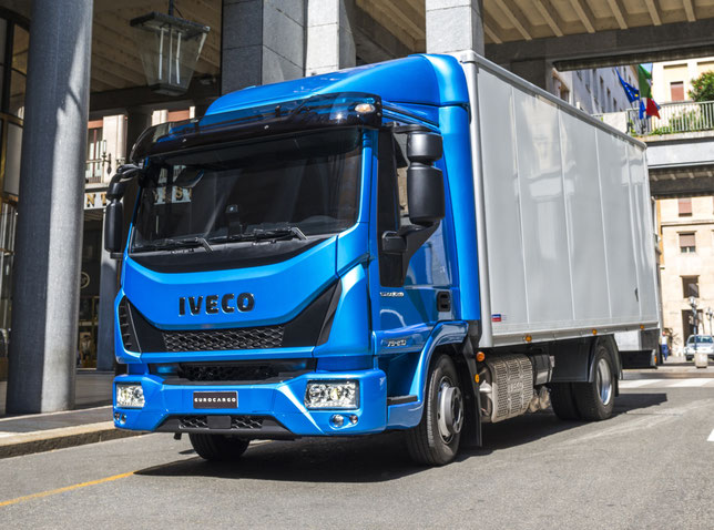
Iveco Euro Cargo repair manual free download.
An operational description of the actions of technical personnel performing repair and maintenance is given, the technical equipment necessary for carrying out certain operations is described.
Recommendations are given and the repair of engines, clutches, gearbox, front and rear axles, steering, brake system, suspension, electrical equipment is described.
The repair manuals are intended for owners of Iveco EuroCargo trucks, technical staff of repair shops and drivers.
A series of Italian trucks Iveco EuroCargo includes various modifications, but at the same time, each car can be considered a standard of its kind,
exemplary technology. Powerful tractors and trucks for the transportation of various goods, assistants in construction — these machines have deservedly earned prestigious titles and
awards, and today they are used by companies that choose equipment that brings real profit. Indeed, every kilometer of Iveco EuroCargo trucks will fully
justify itself and make any large business even more profitable.
The Iveco EuroCargo repair manual should certainly be within the reach of every driver and foreman specializing in foreign trucks. This
manual clearly and accurately answers the most important questions that are directly related to the diagnosis and repair of these machines, their operation, maintenance, design features and
electrical equipment. In short, the book will become a reliable source of information for every day for everyone who is on duty connected with the work of these reliable and powerful trucks,
produced from 2003 to 2008, with a total weight from 6 to 10 tons.
The content of the technical manual begins with a chapter — the Iveco EuroCargo owners manual, where you can learn everything about the
features of the machine, including the components of the truck, their technical characteristics. Then Iveco EuroCargo maintenance chapter, including how to properly troubleshoot minor
problems — such procedures can even be performed by a novice user. It also specifies the exact schedule of all required inspections and inspections, and visual rules for their implementation.
When repairing or adjusting electrical equipment, the master will need Iveco EuroCargo electrical wiring diagrams. They will be needed in case of improvement of the electrics of the
truck, the connection of new devices. On the last pages of the book indicated the designation of the colors of the wiring of electrical circuits.
See also: Iveco trucks wiring diagrams free
download
In the most detailed way and as much as possible available in this manual, the issues of diagnostics and repair of the truck are considered, illustrated in details descriptions of the
installation and repair of the engine, clutch, gearbox, rear axle, steering, braking system, suspension. Knowing how to correctly and gradually carry out repairs, adjustment, assembly,
disassembly of these elements of the machine, you can effectively solve the repair tasks of any complexity on the basis of car service or in a garage workshop.
Iveco EuroCargo 75E16/17 owner’s, operators, service and maintenance manuals, error codes list, DTC, spare parts manuals & catalogues, wiring diagrams, schematics free download PDF
See also:
| Title | File Size | Download Links |
| Iveco EuroCargo Repair Manual [RAR] | 45.6Mb | Download |
| Iveco EURO Range Bodybuilders Instructions PDF [PDF] | 7.5Mb | Download |
| Iveco EuroCargo 4 / 5 Repair Manual [PDF] | 45.2Mb | Download |
| IVECO EUROCARGO 6-10T – REPAIR MANUAL [PDF] | 40.1Mb | Download |
| Iveco EuroCargo Electrical Service Manual 2003 [PDF] | 5.7Mb | Download |
| Iveco EuroCargo Engine Service Repair Manual [PDF] | 8.7Mb | Download |
| Iveco Eurocargo Motor Tector Sistema EDC [PDF] | 1.6Mb | Download |
| Iveco EuroCargo PDF Service Manual [PDF] | 2.9Mb | Download |
| Iveco EuroCargo Technical Specifications [PDF] | 7.3Mb | Download |
| Iveco EuroCargo Tector 12 to 26 t Repair Manual [PDF] | 51.3Mb | Download |
Iveco EuroCargo Maintenance Manuals
Iveco EuroCargo TECTOR is a powerful truck, reliable and high-tech. This type of vehicle is devoted to the data of the Iveco EuroCargo repair and owner’s manual (with engines for 4 and 6 cylinders, carrying capacity from 6 to 26 tons), its maintenance, and operation features.
The repair and maintenance manual will undoubtedly be helpful and even indispensable for all Iveco EuroCargo owners (including those who are just about to purchase such a truck), maintenance station specialists, car service workers, as well as everyone who is somehow connected with the operation, repair and maintenance of this vehicle (for example, those drivers who, on duty, drive this powerful truck every day).
The Iveco EuroCargo repair manual will be clear even to novice motorists in terms of the availability of the presentation of the material, even though a lot of space is devoted to solving repair problems in the manual, which are often quite tricky. In any case, even if it will be difficult for a motorist to cope with diagnostics and troubleshooting on his own, having this practical manual at hand, he will get a complete picture of what kind of repair procedures and to what extent should be carried out by car service specialists, which will allow him to communicate competently with employees and avoid possible deception on their part.
All steps related to identifying and eliminating problems in the Iveco EuroCargo are well illustrated and provided with all the necessary explanations. If the repair procedure requires several step-by-step actions, each has a footnote to the place in the manual where it is described in detail.
With this Iveco EuroCargo manual, you will learn how to assemble, disassemble, repair, lubricate and, if necessary, replace Iveco EuroCargo units and systems: engines, clutches, gearboxes, front and rear axles, brake system, steering, suspension, etc.
Also on the pages of the manual are the Iveco EuroCargo wiring diagrams, the principles of their operation, and the main stages of repairing the car’s electrical equipment.

Iveco EuroCargo
Since unforeseen breakdowns often occur along the way, the manual provides the main problem situations that can come as a complete surprise to a driver in a hurry about his business and the best ways to solve them without using outside help.
Also presented are the Iveco EuroCargo operating instructions, as well as the features of the maintenance and operation of this truck. After all, only competent car care and proper use of vehicles reduce the risk of accidents and extend the car’s life.
The appendix to this practical guide contains a lot of helpful information (for example, how to maintain safety on the roads, how to prepare for the first trip of a truck, recommendations from experienced motorists, as well as various summary tables and Iveco EuroCargo wiring diagrams).
- Manuals
- Brands
- Iveco Manuals
- Automobile
- Eurocargo Euro 6
- Instructions manual
-
Contents
-
Table of Contents
-
Bookmarks
Related Manuals for Iveco Eurocargo Euro 6
Summary of Contents for Iveco Eurocargo Euro 6
-
Page 1
UROCARGO ODYBUILDERS INSTRUCTIONS SSUE 2013… -
Page 2
IVECO S.p.A Technical Application & Homologation Strada delle Cascinette, 424/34 10156 Torino (TO) — Italy www.iveco.com Printed 603.95.747 – 1 ed. 12/2013 Images and text: IVECO S.p.A. 2013 All rights reserved. -
Page 3
EUROCARGO Euro 6 – GUIDELINES FOR TRANSFORMATION AND GUIDELINES FOR TRANSFORMATION AND VERSIONS UPDATE DATA GUIDELINES FOR TRANSFORMATION AND VERSIONS UPDATE DATA Section Description Page Revision date – Printed 603.95.747 – 1st Ed. — Base 12/2013… -
Page 4
— Printed 603.95.747 – Base 12/2013… -
Page 5
Data and information contained in this publication may be outdated as a result of changes adopted by IVECO, at any time, for tech- nical or commercial reasons or due to the need to adapt the vehicle to new legal requirements. -
Page 6
— Printed 603.95.747 – Base 12/2013… -
Page 7
INDEX OF SECTIONS GENERAL INFORMATION CHASSIS INTERVENTIONS APPLICATIONS OF SUPERSTRUCTURES POWER TAKE-OFFS ELECTRONIC SUB-SYSTEMS SPECIAL INSTRUCTIONS FOR SCR EXHAUST SYSTEM — Printed 603.95.747 – Base 12/2013… -
Page 8
— Printed 603.95.747 – Base 12/2013… -
Page 9
SECTION 1 GENERAL INFORMATION — Printed 603.95.747 – Base 12/2013… -
Page 10
— Printed 603.95.747 – Base 12/2013… -
Page 11: Table Of Contents
ELECTRONICALLY ….. . . 1.3 IVECO AUTHORISATION ….
-
Page 12
EUROCARGO Euro 6 – GENERAL INFORMATION GENERAL INFORMATION – Printed 603.95.747 – 1st Ed. — Base 12/2013… -
Page 13: Scope Of The Guidelines
It should be noted that the collaboration with IVECO is based on the assumption that the Bodybuilder uses the maximum of their technical and organisational skills and that operations are technically and perfectly complete. As outlined below, the topic is extens- ive and we can only provide the rules and minimum precautions that can allow development of the technical initiative.
-
Page 14: Authorisation Request
● the implementation; ● the compliance of the design and implementation to any specific indications provided by IVECO and the laws in force in the countries where the vehicle is destined; ● effects on functionality, safety, reliability and, in general, good behaviour of the vehicle;…
-
Page 15: Guarantees
(e.g. approval documents/test reports). Before signing the Technical Agreement IVECO reserves the right to visit the Bodybuilder, in order to verify qualifications to carry out the fittings and/or processing for which the above collaboration is requested.
-
Page 16: Quality System Management
● training and qualification of staff. The availability of ISO 9001 certification, even though not required, is considered very important by IVECO. 1.10 ACCIDENT PREVENTION Do not allow unauthorised staff to intervene or operate on the vehicle. It is forbidden to use the vehicle with safety devices that have been tampered with or are damaged.
-
Page 17: Vehicle Management On The Part Of Bodybuilder
● carry out the controls set forth in the Pre-Delivery Inspection (PDI) list available in the IVECO network, for the items being worked on (obviously the other items of the PDI will be the responsibility of the Dealer, such as the guarantee pamphlet);…
-
Page 18: Vehicle Names
EUROCARGO Euro 6 – GENERAL INFORMATION GENERAL INFORMATION 1.13 VEHICLE NAMES 1.13 VEHICLE NAMES The commercial names (an example follows) of IVECO vehicles do not coincide with approval names. Commercial name EUROCARGO MLC 120 E 19 / P ● EUROCARGO – Vehicle name ●…
-
Page 19: Trademarks And Symbols
The dimensions and masses of vehicles allowed on the axles are shown in the drawings, the technical descriptions and, more gener- ally, on the documents on the official IVECO website. Defects refer to vehicles in their standard versions; the use of special equip- ment may lead to changes on the masses and their distribution on the axles.
-
Page 20: Determination Of The Centre Of Gravity Of The Superstructure And The Payload
EUROCARGO Euro 6 – GENERAL INFORMATION GENERAL INFORMATION 1.15 DIMENSIONS AND GROUND Transfer Extra space occupied rear cab fitting Reduction Vehicle Engines Engines towards the bar body E22/E25 E28/E32 under-run protection 110EL, 120EL, 120, 140, 150, 160 115 mm 115 mm…
-
Page 21
EUROCARGO Euro 6 – GENERAL INFORMATION GENERAL INFORMATION 1.15 DIMENSIONS AND GROUND In the realisation of the superstructure or containers, automatic loading and unloading of the goods transported must be provided to avoid excessive variations of the distribution and/or excessive loads on the axles, providing information for users if necessary. -
Page 22
● considering (for liquids) the density; ● prescribing the implementation of adequate precautions for driving. Any cases where evaluation is difficult should be submitted to IVECO for approval. – Printed 603.95.747 – 1st Ed. — Base 12/2013… -
Page 23: Respect Of The Permitted Masses
Respect of the permitted masses All the limits shown on IVECO documentation must be respected. It is particularly important to evaluate the maximum ground on the front axle in any load condition, in order to ensure the necessary steering features in all road surface conditions.
-
Page 24: Instructions For Proper Functioning Of The Vehicle Parts And Accessibility
EUROCARGO Euro 6 – GENERAL INFORMATION GENERAL INFORMATION 1.16 INSTRUCTIONS FOR PROPER FUNCTIONING OF THE VEHICLE PARTS AND ACCESSIBILITY Variations on permitted masses Special exemptions from the maximum permissible masses may be granted for specific uses, for which, however, there are precise limits for use and reinforcements to be made to parts of the vehicle.
-
Page 25
EUROCARGO Euro 6 – GENERAL INFORMATION GENERAL INFORMATION 1.16 INSTRUCTIONS FOR PROPER FUNCTIONING OF THE VEHICLE PARTS AND ACCESSIBILITY Figure 6 196793 1. A. Possible fitting size limit Right-hand side view 2. B. Upper chassis wire Left-hand side view 3. -
Page 26
EUROCARGO Euro 6 – GENERAL INFORMATION GENERAL INFORMATION 1.16 INSTRUCTIONS FOR PROPER FUNCTIONING OF THE VEHICLE PARTS AND ACCESSIBILITY Figure 7 196798 1. 3. Body surface Lateral protrusion diesel oil pre-filter 4. 2. Lateral protrusion AdBlue tank Lateral protrusion silencer protection Table 1.2 — Sizes of the most protruding units… -
Page 27: General Regulation For The Prevention Of Fire Risk
EUROCARGO Euro 6 – GENERAL INFORMATION GENERAL INFORMATION 1.17 GENERAL REGULATION FOR THE PREVENTION OF FIRE RISK 1.17 GENERAL REGULATION FOR THE PREVENTION OF FIRE RISK Particular attention must be paid to prevent the spillage of hydraulic fluids or inflammable liquids above components which may become hot or overheated.
-
Page 28
EUROCARGO Euro 6 – GENERAL INFORMATION GENERAL INFORMATION – Printed 603.95.747 – 1st Ed. — Base 12/2013… -
Page 29
SECTION 2 CHASSIS INTERVENTIONS — Printed 603.95.747 – Base 12/2013… -
Page 30
— Printed 603.95.747 – Base 12/2013… -
Page 31
EUROCARGO Euro 6 – CHASSIS INTERVENTIONS CHASSIS INTERVENTIONS Contents Contents 2.7 ASSEMBLING AN ADDITIONAL AXLE ..General information …. -
Page 32
EUROCARGO Euro 6 – CHASSIS INTERVENTIONS CHASSIS INTERVENTIONS Contents 2.17 PART RELOCATION AND ANCHORAGE OF ADDITIONAL UNITS AND EQUIPMENT ..2.18 TRANSPORT OF HAZARDOUS MATERIALS (ADR) …… -
Page 33: General Chassis Modification Standards
EUROCARGO Euro 6 – CHASSIS INTERVENTIONS CHASSIS INTERVENTIONS 2.1 GENERAL CHASSIS MODIFICATION STANDARDS CHASSIS INTERVENTIONS 2.1 GENERAL CHASSIS MODIFICATION STANDARDS Keep in mind that: ● weldings on the supporting structures of the chassis are absolutely forbidden (except as prescribed in Para- graph»Weldings» ( ➠ Page 9) and in Chapters 2.4 ( ➠ Page 15), and 2.5 ( ➠ Page 17));…
-
Page 34: Characteristics Of The Material Used In Chassis Modifications
— either by filing and/or with a suitable chemical based solution — the paint on both the chassis and ter- minal side, thus creating a contact surface free of indentations and edges; ● paint the area between the terminal and metal surface with a high conductivity paint (e.g. zinc coating Part Number IVECO 459622 from PPG); ●…
-
Page 35: Stresses On The Chassis
EUROCARGO Euro 6 – CHASSIS INTERVENTIONS CHASSIS INTERVENTIONS 2.2 DRILLS ON THE CHASSIS Wheelbase [mm] A x B Model 2790 3105 3330 3690 4185 4455 4815 [mm] Thickness t [mm] 80E, 90E, 100E 195×65 Wheelbase [mm] A x B Model…
-
Page 36: Hole Position And Size
EUROCARGO Euro 6 – CHASSIS INTERVENTIONS CHASSIS INTERVENTIONS 2.2 DRILLS ON THE CHASSIS Hole position and size The new holes must not be drilled into the areas subjected to greater stresses (such as spring supports) or where the side member section varies.
-
Page 37: Welds
EUROCARGO Euro 6 – CHASSIS INTERVENTIONS CHASSIS INTERVENTIONS 2.2 DRILLS ON THE CHASSIS Welds When welding, drilling, milling and cutting near brake hoses and electrical wires, be sure to ad- ▶ opt appropriate precautions for their protection; disconnect these parts if necessary (respect the prescriptions in Chapters 2.15 and 5.7).
-
Page 38
EUROCARGO Euro 6 – CHASSIS INTERVENTIONS CHASSIS INTERVENTIONS 2.2 DRILLS ON THE CHASSIS Weld operations ● Thoroughly remove paint and rust from the chassis where welds will be made, as well as all parts that will be covered by rein- forcements. -
Page 39: Sealing Holes By Welding
Holes of 20 mm diameter can be sealed off by using chamfered washers welded on both sides. 2.3 RUST AND PAINT PROTECTION Note All components mounted on the chassis must be painted in compliance with IVECO Standard 18-1600 Colour IC444 RAL 7021 — 70/80 gloss.
-
Page 40
See Table III Coupling with other materials must not cause the «battery effect”. Coatings free from chromium salts. Coatings free of hexavalent chromium. Table 2.6 — Painted parts — IVECO Standard 18 — 1600 (Prospectus III) Classes Cycle phase description –… -
Page 41: Added Or Modified Parts
EUROCARGO Euro 6 – CHASSIS INTERVENTIONS CHASSIS INTERVENTIONS 2.3 RUST AND PAINT PROTECTION Excluding parts that cannot be immersed in pre-treatment baths or undergo painting because of compromised functionality (e.g.: mech- anical parts). Only if the colour is defined in a drawing according to I.C.
-
Page 42: Precautions
EUROCARGO Euro 6 – CHASSIS INTERVENTIONS CHASSIS INTERVENTIONS 2.3 RUST AND PAINT PROTECTION Precautions On the vehicle Appropriate precautions must be taken to protect parts on which paint could be harmful to the conservation and operation thereof: ● hoses for pneumatic and hydraulic systems in rubber or plastic, with particular reference to the braking system;…
-
Page 43: Wheelbase Modification
If the dimensions of the superstructure are suitable, it is best to use wheelbases in standard production because this allows the use of original drive shafts and pre-defined crossbar positions. Nevertheless, IVECO must issue its authorisation for wheelbases below the minimum or maximum approved standard sizes on the market.
-
Page 44: Effects On Braking
— along the entire contour of the wheelbase — until achieving area strength modulus equal to IVECO values for the same wheelbase or for the next admissible greater length. In alternative, for cases allowed by local standards, larger counter-frame profiles can be adopted.
-
Page 45: Cross Members
When modifying the rear overhang it is necessary to take note of the variations that this modification inflicts on distribution of axle loads, in compliance with loads established by IVECO (see Chapter 1.15 ( ➠ Page 11)). Limits set by national law must also be respected, as well as maximum distances from the rear structural edge and distance from ground, defined for towing hook and under-run protection.
-
Page 46: Authorisation
EUROCARGO Euro 6 – CHASSIS INTERVENTIONS CHASSIS INTERVENTIONS 2.5 REAR OVERHANG MODIFICATION Authorisation Rear frame elongation as well as shortening to the smallest value for each model of the series do not require authorisation if per- formed in compliance with the instructions provided herein.
-
Page 47
EUROCARGO Euro 6 – CHASSIS INTERVENTIONS CHASSIS INTERVENTIONS 2.5 REAR OVERHANG MODIFICATION Figure 7 91454 1. Added part 3. Reinforcing profile (alternative solution) 2. Reinforcing profile 4. Original rear cross member Figure 8 91455 1. Added part 3. Original rear cross member 2. -
Page 48: Installing The Tow Hook
430 for adaptation to towing a trailer. The installation on vehicles to which the drawbar coupling is not originally provided must be authorized by IVECO. For trailers with one or more close axles (central axle trailers), taking into account the stresses to which the rear crossbar is sub- jected, particularly due to the dynamic vertical loads, keep in mind the precautions given in Paragraph «Towing hook for centre axle…
-
Page 49
EUROCARGO Euro 6 – CHASSIS INTERVENTIONS CHASSIS INTERVENTIONS 2.6 INSTALLING THE TOW HOOK Figure 9 196787 1. 2. Free field for towing hooks Free field for coupling hooks according to standard DIN 74058 ESC-152 In cases where the connection flange of the drawbar coupling does not have holes suitable to those on the existing rear crossbar of the vehicle, the latter may be authorised for modification upon application of adequate reinforcements. -
Page 50: Towing Hooks For Conventional Trailers
EUROCARGO Euro 6 – CHASSIS INTERVENTIONS CHASSIS INTERVENTIONS 2.6 INSTALLING THE TOW HOOK Towing hooks for conventional trailers According to Directive 94/20/CE, both for the choice of the hook and for the application of any reinforcements to the rear cross- bar, it is important to take into account the action of the horizontal forces generated by the masses of the tractor and trailer, based on the following formula: D = 9.81 (T •…
-
Page 51
L. Theoretical drawbar length If you wish to use the tow with a vehicle not originally designed (and in compliance with the limits established by IVECO for each model), only original rear crossbars which have already been hole punched can be mounted. Towable masses and the bearable vertical loads can be defined based on the size of the hole. -
Page 52
EUROCARGO Euro 6 – CHASSIS INTERVENTIONS CHASSIS INTERVENTIONS 2.6 INSTALLING THE TOW HOOK R = Maximum weight of trailer [kg] S = Vertical static load on the trailer hook [kg] Over- Profile Wheel- R≤4500 R≤6500 R≤9500 R≤10500 R≤12000 R≤14000 R≤16000 R≤18000… -
Page 53
EUROCARGO Euro 6 – CHASSIS INTERVENTIONS CHASSIS INTERVENTIONS 2.6 INSTALLING THE TOW HOOK R = Maximum weight of trailer [kg] S = Vertical static load on the trailer hook [kg] Over- Profile Wheel- R≤4500 R≤6500 R≤9500 R≤10500 R≤12000 R≤14000 R≤16000 R≤18000… -
Page 54
EUROCARGO Euro 6 – CHASSIS INTERVENTIONS CHASSIS INTERVENTIONS 2.6 INSTALLING THE TOW HOOK R = Maximum weight of trailer [kg] S = Vertical static load on the trailer hook [kg] Over- Profile Wheel- R≤4500 R≤6500 R≤9500 R≤10500 R≤12000 R≤14000 R≤16000 R≤18000… -
Page 55
EUROCARGO Euro 6 – CHASSIS INTERVENTIONS CHASSIS INTERVENTIONS 2.6 INSTALLING THE TOW HOOK R = Maximum weight of trailer [kg] S = Vertical static load on the trailer hook [kg] Over- Profile Wheel- R≤4500 R≤6500 R≤9500 R≤10500 R≤12000 R≤14000 R≤16000 R≤18000… -
Page 56: Rear Crossbar In Lowered Position
Rear crossbar in lowered position When the drawbar coupling must be lowered from its original position, IVECO may issue an authorisation to lower the original drawbar or install an additional drawbar, which is the same as the original, in a lowered positioned.
-
Page 57
EUROCARGO Euro 6 – CHASSIS INTERVENTIONS CHASSIS INTERVENTIONS 2.6 INSTALLING THE TOW HOOK Figure 12 192343 1. Original rear cross member. 3. Overturned gusset plate 2. Gusset plate 4. Connecting corner The outer corners should have a thickness of not less than that of the side members of the vehicle, they should extend in length for a distance of at least 2.5 times the height of the side member itself (min 600 mm) and should use a material with the minimum… -
Page 58
EUROCARGO Euro 6 – CHASSIS INTERVENTIONS CHASSIS INTERVENTIONS 2.6 INSTALLING THE TOW HOOK Figure 13 192344 1. Original rear cross member. 4. Connecting plate 2. Connecting plate or angle 5. C-profile (same dimensions as chassis) 3. Coupling plate 6. Space for rear spring retainer The movements between the drawbar and the vehicle established by regulations in force must be ensured. -
Page 59
EUROCARGO Euro 6 – CHASSIS INTERVENTIONS CHASSIS INTERVENTIONS 2.6 INSTALLING THE TOW HOOK Tow beam in a lowered and forward position (close coupling) for centre axle trailers Vehicles that, to tow centre axle trailers, must adopt a two beam in a lowered and forward position (close to the rear housings of the rear suspension or air springs), do not require special chassis reinforcement. -
Page 60
Chapter 1.15 ( ➠ Page 11). Increase of tow weight As regards tow vehicles, IVECO may evaluate — in certain cases and for particular applications — the possibility to authorise greater tow weights than those normally allowed. -
Page 61: Assembling An Additional Axle
On some models of the EuroCargo range, it may be possible to apply an additional axle and consequently increase the gross vehicle weight. For its implementation, the mass limits and conditions imposed by IVECO must be respected, as well as all other conditions reques- ted by national laws and the necessity to ensure driving safety and proper vehicle function.
-
Page 62: Added Axle
EUROCARGO Euro 6 – CHASSIS INTERVENTIONS CHASSIS INTERVENTIONS 2.7 ASSEMBLING AN ADDITIONAL AXLE In the case of a counter chassis reinforcement, the anchors provided on the chassis may be used (if in existence), otherwise they should be made according to the indications in Chapter 3.1 — Paragraph «Sizing of profiles» and subsequent paragraphs.
-
Page 63: Steering Axles
● The application of a controlled steering axle, obtained through the original device of the vehicle’s steering system, requires authorisation from IVECO upon presentation of the supplementary system diagram. Suspension The construction quality of all the components must be ensured (axle, suspension, brake assemblies, systems etc.) in order to guar- antee the driving safety and the correct functioning of the vehicle.
-
Page 64: Stabiliser Bars
Exception is made for outfits or special uses for which, in order to increase suspension rigidity, the application of rubber elastic elements may be authorised. In special cases and only after IVECO approval, the addition of supplemental sheets on the parabolic springs may be allowed; this must be carried out by a specialised spring manufacturer.
-
Page 65: Lifting Device
The maximum tilt values of the drive shaft for the vehicle series must be respected, even for interventions on the rear engine axle suspensions. Contact the IVECO Technical Application for any difficulties; and send them a diagram with the length and tilt of the new transmis- sion for a constant-velocity check.
-
Page 66: Lengths Allowed
EUROCARGO Euro 6 – CHASSIS INTERVENTIONS CHASSIS INTERVENTIONS 2.8 GEARBOX MODIFICATION Figure 19 196780 Maximum allowed angularity n = engine speed β • n < 20000 for classes 2040-2045-2050 β • n < 25000 for classes 2025-2030-2035 Values that m ust be valid both when the vehicle is empty (tare only) and when the vehicle has a static load considering the max- imum allowed load on the rear axle.
-
Page 67
EUROCARGO Euro 6 – CHASSIS INTERVENTIONS CHASSIS INTERVENTIONS 2.8 GEARBOX MODIFICATION For sliding shafts, the length LG must be evaluated between the universal joint centres and with the sliding stem in the intermediate position. Always check both stems LG and LZ. -
Page 68: Positioning The Sections
EUROCARGO Euro 6 – CHASSIS INTERVENTIONS CHASSIS INTERVENTIONS 2.8 GEARBOX MODIFICATION Note Usually, the fork universal joints of the same shaft must not be rotated. Pipe thickness Valid tube thickness is usually not possible. In fact, pipe thickness depends on the torque that the original shaft must transmit, as well as on the specifications of the transmis- sion line (torque, power train ratio, axle loads or drive axles).
-
Page 69
EUROCARGO Euro 6 – CHASSIS INTERVENTIONS CHASSIS INTERVENTIONS 2.8 GEARBOX MODIFICATION Figure 21 91451 1. Drive shaft, clutch, gearbox 6. Rear axle casing tilt (max compression) 2. Intermediate shaft 7. Rear axle casing tilt (no load) 3. Intermediate shaft bearing 8. -
Page 70
Furthermore, the wheelbase on these vehicles may not be reduced beyond the shortest value for the series (e.g. tipper truck). We recommend using original IVECO gearboxes; if this is not possible, the use of raw steel pipes with a yield load of at least 420… -
Page 71: Modifying The Engine Air Intake And Exhaust Systems
Manufacturer. 2.9 MODIFYING THE ENGINE AIR INTAKE AND EXHAUST SYSTEMS Note The characteristics of the engine air intake and exhaust systems must not be modified. Modifications, if authorised by IVECO, must not vary the original intake vacuum and exhaust counter-pressure values.
-
Page 72: Engine Exhaust
EUROCARGO Euro 6 – CHASSIS INTERVENTIONS CHASSIS INTERVENTIONS 2.10 MODIFYING THE ENGINE COOLING SYSTEM Engine exhaust Given the compaction of the “Hi-e SCR” system (see Section 6 ( ➠ Page 5)) and the optimal arrangement of its assemblies on the chassis, any modifications to the exhaust pipe formation may be permitted only for the realization of a vertical exhaust outlet, differing from that offered as optional 180.
-
Page 73: Installing An Additional Heating System
We recommend using IVECO type heating systems whenever it is necessary to install an additional heating system. On vehicles where IVECO does not employ these heaters, installation must be done in compliance with the instructions issued by the equipment Manufacturer (installation of heaters, pipes, electric system, etc.) and in relation to the following indications.
-
Page 74: Installing An Air Conditioning System
● installation of the evaporator unit and of the bellow inside the cab (in cases where not provided directly from IVECO) must be planned as not to negatively impact control functions and access to equipment; b) cab roof-installed systems : ●…
-
Page 75: Work On The Roof
The transformation of the standard cab to a special cab or sleeper cab (special vehicles, public use, fire brigade, etc.) can be author- ised by IVECO after the evaluation of the suitability of use of the suspension, tipping and locking systems to operate correctly even under the new conditions.
-
Page 76: Changing Tyre Size
Note Replacing tyres with others of different external diameter affects vehicle performance (e.g.: speed, max. vehicle ramp slope, tow load, braking force, etc.); therefore the IVECO Body Controller (speedometer, tachograph and speed limiter) must undergo recalib- ration at an authorised IVECO workshop.
-
Page 77: Work On The Braking System
▶ between rim and connection flange are clean and free of corrosion when remounting the wheels. In addition, tighten the wheel studs at the tightening torque according to the IVECO standard (see the following Table). Table 2.15 — Wheel tightening torque according to IVECO STD 17-9219…
-
Page 78
● on hydraulic lines. Operations must provide: ● materials and dimensions: Standard DIN 74324 (IVECO STD 18-0400) Maximum operating pressure 12.5 bar ● radii of curvature (referring to the centre line of the pipe): ■ Φ 6 to 35 mm ■… -
Page 79
EUROCARGO Euro 6 – CHASSIS INTERVENTIONS CHASSIS INTERVENTIONS 2.15 WORK ON THE BRAKING SYSTEM Before inserting the pipe into the coupling, screw the coupling into the threaded insert of the same component (e.g. pneumatic valve), using the following values for tightening: … -
Page 80: Abs Electronic Brake Control Devices
EUROCARGO Euro 6 – CHASSIS INTERVENTIONS CHASSIS INTERVENTIONS 2.15 WORK ON THE BRAKING SYSTEM Figure 25 193866 To ensure that the connections have been properly made, the air tank corresponding to an axle can be emptied; the pressure con- trol on the in-vehicle indicator and the verification, by operating the brake pedal, on the remaining braking section(s), allow such verification.
-
Page 81: Electrical System: Current Interventions And Draws
EUROCARGO Euro 6 – CHASSIS INTERVENTIONS CHASSIS INTERVENTIONS 2.16 ELECTRICAL SYSTEM: CURRENT INTERVENTIONS AND DRAWS Figure 26 196783 If you require larger quantities of air you have to assemble an additional tank. In this case, however, it is necessary to ensure that the standard compressor is able to fill the tank within the specified time, other- wise you will need to install a higher capacity compressor.
-
Page 82
The displacement of the horn obligates the body builder for a new approval. Also in the new position, the device must ensure the acoustic performance set by the regulations and must be adequately protected from exposure of weathering and/or soiling. IVECO reserves the right to void the warranty on the moved component. -
Page 83: Transport Of Hazardous Materials (Adr)
(see end of paragraph). IVECO does not provide versions fully prepared for the ADR, although production vehicles do already comply for some electrical parts, mechanical components and materials inside the cab. The Bodybuilder, upon request, is given a «declaration» containing details of the sections in the ECE document that have already been complied with by the vehicle up from the origin.
-
Page 84
Since this is not within the content of the ADR preparation given by IVECO, when ordering the vehicle must be chosen the optional 00741 «Without rear glazing”. -
Page 85: Installing A Retarder
The installation of a retarder brake is complex and requires the perfect integration with electric ▶ and electronic vehicle systems: therefore approval by IVECO is always necessary. While advising against the adoption of a retarder that is not like the one available in option for the first equipment, we do not ex- clude the option of selecting one of a different type (e.g.
-
Page 86: Rear Under-Run Protection (Rup)
2.21 REAR MUD GUARDS AND WHEEL ARCHES On cab version vehicles without rear fenders, the Bodybuilder must implement solutions equal to those provided by IVECO. For the realisation of the fenders, the wheel arch boxes and the shaping of the superstructure, keep in mind that: ●…
-
Page 87: Rain Flap
EUROCARGO Euro 6 – CHASSIS INTERVENTIONS CHASSIS INTERVENTIONS 2.22 RAIN FLAP 2.22 RAIN FLAP In cases where legislation requires it and if not present yet, it is necessary to ensure that the complete vehicle is equipped with suitable rain flaps. For installation, it is necessary to comply with the distances required by the laws in force.
-
Page 88
EUROCARGO Euro 6 – CHASSIS INTERVENTIONS CHASSIS INTERVENTIONS 2.23 SIDE PROTECTIONS Figure 32 196788 B Permissible sag under the test load: ≤ 30 mm on the A With the lower part of the superstructure over 1300 mm rear part (last 250 mm of the device); ≤ 150 mm on from the ground, or with the width of the superstructure below the external tyre dimension. -
Page 89: Front Under-Run Protection (Fup)
EUROCARGO Euro 6 – CHASSIS INTERVENTIONS CHASSIS INTERVENTIONS 2.24 FRONT UNDER-RUN PROTECTION (FUP) 2.24 FRONT UNDER-RUN PROTECTION (FUP) For the front under-run protection bar (FUP = Front Underrun Protection) are provided different fixing positions to the chassis. So it is possible to comply with the EC 2000/40 Directive even with the new vehicle setting after the fitting, the new loads on the axes and/or the use of any different tyres.
-
Page 90
EUROCARGO Euro 6 – CHASSIS INTERVENTIONS CHASSIS INTERVENTIONS 2.25 REAR-VIEW MIRRORS Figure 33 131013 – Printed 603.95.747 – 1st Ed. — Base 12/2013… -
Page 91
SECTION 3 APPLICATIONS OF SUPERSTRUCTURES — Printed 603.95.747 – Base 12/2013… -
Page 92
— Printed 603.95.747 – Base 12/2013… -
Page 93
EUROCARGO Euro 6 – APPLICATIONS OF SUPERSTRUCTURES APPLICATIONS OF SUPERSTRUCTURES Contents Contents 3.9 INSTALLATION OF TAIL LIFTS … Base configuration for tail lifts …. -
Page 94
EUROCARGO Euro 6 – APPLICATIONS OF SUPERSTRUCTURES APPLICATIONS OF SUPERSTRUCTURES – Printed 603.95.747 – 1st Ed. — Base 12/2013… -
Page 95: Construction Of The Counter Chassis
Following are the characteristics of certain materials which were taken into account in some of the applications stated below. Table 3.1 — Material to be used for the construction of superstructures Std IVECO 15-2110 and 15-2812 Breaking strength…
-
Page 96: Aluminium Counter Chassis
When the counter chassis is prompted to make a contribution in terms of strength and hardness (e.g. superstructures with high concentrated loads, tipping bodies, cranes, centre axle trailers, etc..), the use of aluminium is generally not recommended and should be authorised from time to time by IVECO. – Printed 603.95.747 – 1st Ed. — Base 12/2013…
-
Page 97: Elements Making Up The Counter Chassis
EUROCARGO Euro 6 – APPLICATIONS OF SUPERSTRUCTURES APPLICATIONS OF SUPERSTRUCTURES 3.2 ELEMENTS MAKING UP THE COUNTER CHASSIS Please note that in defining the minimum size of the reinforcement profiles in addition to the limit of the allowable stress for aluminium, reference must be made to the different Elastic Modulus with respect to steel (approx. 7,000 kg/mm…
-
Page 98
EUROCARGO Euro 6 – APPLICATIONS OF SUPERSTRUCTURES APPLICATIONS OF SUPERSTRUCTURES 3.2 ELEMENTS MAKING UP THE COUNTER CHASSIS The possibility of building a counter chassis with a different width from that of the vehicle chassis is permitted only in special cases (e.g. interchangeable equipment with sliding systems on rollers, where the mechanical or hydraulic devices are unified). In these cases, precautions must be taken to achieve a correct transmission of forces between the structure of the counter chassis and the vertical rib of the chassis. -
Page 99: Cross Members
EUROCARGO Euro 6 – APPLICATIONS OF SUPERSTRUCTURES APPLICATIONS OF SUPERSTRUCTURES 3.2 ELEMENTS MAKING UP THE COUNTER CHASSIS It is necessary to create continuity of support between the profiles of the counter chassis and those of the chassis; if this is not ob- tained, the continuity can be restored by means of interposition of strips of sheet metal or light alloy.
-
Page 100
EUROCARGO Euro 6 – APPLICATIONS OF SUPERSTRUCTURES APPLICATIONS OF SUPERSTRUCTURES 3.2 ELEMENTS MAKING UP THE COUNTER CHASSIS Figure 5 166684 Figure 6 193869 1 Counter chassis 2. Diagonals – Printed 603.95.747 – 1st Ed. — Base 12/2013… -
Page 101: Connection Between Chassis And Counter Chassis
Choosing the type of connection The choice of the type of connection to be used, if not provided by IVECO originally, is very important for the purposes of contri- bution of the counter chassis in terms of strength and rigidity.
-
Page 102: Connection Characteristics
EUROCARGO Euro 6 – APPLICATIONS OF SUPERSTRUCTURES APPLICATIONS OF SUPERSTRUCTURES 3.3 CONNECTION BETWEEN CHASSIS AND COUNTER CHASSIS In anchoring the structure to the chassis, welding must not be performed on the vehicle chassis, ▶ nor may holes be put into its wings.
-
Page 103: Connection With Brackets
EUROCARGO Euro 6 – APPLICATIONS OF SUPERSTRUCTURES APPLICATIONS OF SUPERSTRUCTURES 3.3 CONNECTION BETWEEN CHASSIS AND COUNTER CHASSIS σ = maximum static stress applied to the counter-chassis [N/mm σ = maximum static stress applied to the chassis [N/mm = resistance module of the section of the counter-chassis [mm = resistance module of the section of the chassis [mm ] see chapter 2.1, Paragraph «Stresses on the chassis»…
-
Page 104
In the event in which the vehicle chassis is already equipped with brackets for the attachment of a body of a type established by IVECO, these brackets must be used for this purpose. For the brackets applied to the counter chassis or to the superstructure, resistance characteristics not less than those originally mounted on the vehicle should be provided (see Table 2.1 and Table 3.1). -
Page 105: Connections With Greater Elasticity
EUROCARGO Euro 6 – APPLICATIONS OF SUPERSTRUCTURES APPLICATIONS OF SUPERSTRUCTURES 3.3 CONNECTION BETWEEN CHASSIS AND COUNTER CHASSIS Connections with greater elasticity When the connection needs greater flexibility (e.g. vehicles with high stiffness of the superstructure such as vans, tanks, etc., used on winding roads or in poor conditions, vehicles for special use, etc.), hardware of the type indicated in Figure 3.10 should be adop-…
-
Page 106: Connection With Longitudinal And Transverse Sealing Plates (Rigid Junction)
EUROCARGO Euro 6 – APPLICATIONS OF SUPERSTRUCTURES APPLICATIONS OF SUPERSTRUCTURES 3.3 CONNECTION BETWEEN CHASSIS AND COUNTER CHASSIS For this purpose, it is also possible to use connections by means of screws at the rear end of the chassis as shown in Figure 3.13.
-
Page 107: Mixed Connection
EUROCARGO Euro 6 – APPLICATIONS OF SUPERSTRUCTURES APPLICATIONS OF SUPERSTRUCTURES 3.3 CONNECTION BETWEEN CHASSIS AND COUNTER CHASSIS Figure 12 193875 For the correct use of these plates, please keep in mind that: ● the vertical rib of the chassis should be fastened only after making sure that the counter chassis is snug against the chassis itself;…
-
Page 108: Container Application
Fastening is achieved through specially crafted brackets along the vertical rib of the side members; if such connections have not already been specified by IVECO, they must be made according to the instructions in Paragraph «Connection with brackets» ( ➠ Page 13). To achieve a longitudinal adequate containment, in the case of connections with brackets or clamps it is good practice to provide a rigid connection on the rear overhang (one per side), obtained with screws or plates on the upper wing of the side member (see Figure 3.12 and 3.13).
-
Page 109
EUROCARGO Euro 6 – APPLICATIONS OF SUPERSTRUCTURES APPLICATIONS OF SUPERSTRUCTURES 3.4 CONTAINER APPLICATION The front wall of the body must have the necessary strength and toughness to support the forces generated by the transported load, in the case of sudden and high decelerations. -
Page 110: Tipper Bodies
The use of tipper bodies, rear and three sided, generally subjects the chassis to considerable stress. Therefore, please observe the following indications. The use of a stabiliser bar on all IVECO models for which it is an optional, is recommended. The counter chassis must be: ■…
-
Page 111: Heavy-Duty Services
EUROCARGO Euro 6 – APPLICATIONS OF SUPERSTRUCTURES APPLICATIONS OF SUPERSTRUCTURES 3.4 CONTAINER APPLICATION Figure 16 200446 1. Counter chassis A.Mechanical suspensions 2. Brackets B. Air suspensions 3. Plates 4. Joint cover Heavy-duty services Table 3.5 shows which vehicles may be ordered for heavy-duty services and the indications for the main sections of the counter chassis.
-
Page 112: Light-Duty Services
EUROCARGO Euro 6 – APPLICATIONS OF SUPERSTRUCTURES APPLICATIONS OF SUPERSTRUCTURES 3.4 CONTAINER APPLICATION Section modulus W ] of the minimum section bar of the counter chassis Model Wheel base (mm) (Yield point of the material used = 360 N/mm 80K, 90K, 100K…
-
Page 113: Roll Off Containers
The possibility of installing structures for moving roll-off containers (containers moved down to the ground, by depositing or rear sliding, using an on-board vehicle crane) is not universally applicable and should therefore be assessed with IVECO according to each type of vehicle.
-
Page 114: Tractor For Semi-Trailer
EUROCARGO Euro 6 – APPLICATIONS OF SUPERSTRUCTURES APPLICATIONS OF SUPERSTRUCTURES 3.5 TRACTOR FOR SEMI-TRAILER 3.5 TRACTOR FOR SEMI-TRAILER Not provided. 3.6 TRANSPORT OF INSEPARABLE MATERIALS (TRAILER TRUCKS) Not provided. 3.7 INSTALLATION OF TANKS AND LOOSE MATERIAL CONTAINERS a) Installation with a counter chassis The installation of tanks and containers is carried out, as a rule, using a suitable counter chassis.
-
Page 115
EUROCARGO Euro 6 – APPLICATIONS OF SUPERSTRUCTURES APPLICATIONS OF SUPERSTRUCTURES 3.7 INSTALLATION OF TANKS AND LOOSE MATERIAL CONTAINERS As previously mentioned, the stiff connections positioned in correspondence with the rear suspension mounts are more suitable for transmitting forces directly to the suspension elements; elastic connections are to be arranged near the front suspension rear mount. -
Page 116: Installing A Crane
Special cases, whose M value falls within the areas designated by letter “E” in the mentioned Table (or for higher values) must be checked individually each time and must receive specific authorisation from IVECO. – Printed 603.95.747 – 1st Ed. — Base 12/2013…
-
Page 117: Crane Behind Cab
EUROCARGO Euro 6 – APPLICATIONS OF SUPERSTRUCTURES APPLICATIONS OF SUPERSTRUCTURES 3.8 INSTALLING A CRANE Figure 20 200448 g = acceleration of gravity equals 9.81 m/s F = mass applied to crane extremity [kg] L = horizontal distance between the load application point F and vehicle centre line [m] P = mass of the crane at its centre of gravity [kg]…
-
Page 118
EUROCARGO Euro 6 – APPLICATIONS OF SUPERSTRUCTURES APPLICATIONS OF SUPERSTRUCTURES 3.8 INSTALLING A CRANE Figure 21 200449 1. 3. Reinforcing profile Crane connections 2. 4. Connections Stabilisers Table 3.8 — Crane behind cab (counter chassis secured with shelves or flanges) -
Page 119
In the crane area, brace the reinforcement profile sections which have a thickness of less than 5 mm. E = To be checked case-by-case. Send IVECO technical documentation with verification of stress and stability. In the long cab version use a section with modulus of resistance W not less than 57 cm Note For the dimensions of the profiles see Table 3.2. -
Page 120
Table 3.10, on condition that the wing width and thickness are not less than those of the section recommended by IVECO (Table 3.9). The possibility of using materials with superior mechanical characteristics requires verification of the total moment of resistance of the chassis plus counter chassis. -
Page 121: Crane At Rear Overhang
EUROCARGO Euro 6 – APPLICATIONS OF SUPERSTRUCTURES APPLICATIONS OF SUPERSTRUCTURES 3.8 INSTALLING A CRANE 150x50x8 + 130x50x8 + Example of combined sections in alternative to C 250x80x8 [mm] 210x80x8 190x80x8 angle angle Actual reduction in height [mm] Figure 23 204633 1.
-
Page 122
EUROCARGO Euro 6 – APPLICATIONS OF SUPERSTRUCTURES APPLICATIONS OF SUPERSTRUCTURES 3.8 INSTALLING A CRANE Considering that the necessary counter chassis rigidity depends on various factors (e.g. crane capacity, resting surface dimensioning, vehicle tare weight, chassis overhang), instructions valid for all situations cannot be given. For this reason bodybuilders shall, if ne- cessary, proceed also by testing the vehicle’s stability. -
Page 123
Table 3.12, provided that the width of the wing and thickness are not less than those of the section recommended by IVECO (Table 3.11). The possibility of using materials with superior mechanical characteristics requires verification of the total moment of resistance of the chassis plus counter chassis. -
Page 124: Removable Cranes
EUROCARGO Euro 6 – APPLICATIONS OF SUPERSTRUCTURES APPLICATIONS OF SUPERSTRUCTURES 3.9 INSTALLATION OF TAIL LIFTS Removable cranes The installation of removable cranes on the rear overhang may be carried out according to the specifications of the previous para- graph provided the type of fixing used between the crane and the counter chassis does not cause additional stress to the vehicle’s frame.
-
Page 125
EUROCARGO Euro 6 – APPLICATIONS OF SUPERSTRUCTURES APPLICATIONS OF SUPERSTRUCTURES 3.9 INSTALLATION OF TAIL LIFTS Figure 25 204638 = Weight of tail lift = Tail lift capacity The bending moment on the chassis may be obtained using the following ratio: B for tail lifts without stabilisers… -
Page 126
EUROCARGO Euro 6 – APPLICATIONS OF SUPERSTRUCTURES APPLICATIONS OF SUPERSTRUCTURES 3.9 INSTALLATION OF TAIL LIFTS Tail lift capacity in kN (kg) 12.5 17.5 Wheelbase Overhang (750) (1000) (1250) (1500) (1750) (2000) (2500) (3000) Model [mm] [mm] Minimum value of counter chassis section modulus of resistance W… -
Page 127
EUROCARGO Euro 6 – APPLICATIONS OF SUPERSTRUCTURES APPLICATIONS OF SUPERSTRUCTURES 3.9 INSTALLATION OF TAIL LIFTS Tail lift capacity in kN (kg) 12.5 17.5 Wheelbase Overhang (750) (1000) (1250) (1500) (1750) (2000) (2500) (3000) Model [mm] [mm] Minimum value of counter chassis section modulus of resistance W… -
Page 128
EUROCARGO Euro 6 – APPLICATIONS OF SUPERSTRUCTURES APPLICATIONS OF SUPERSTRUCTURES 3.9 INSTALLATION OF TAIL LIFTS Tail lift capacity in kN (kg) 12.5 17.5 Wheelbase Overhang (750) (1000) (1250) (1500) (1750) (2000) (2500) (3000) Model [mm] [mm] Minimum value of counter chassis section modulus of resistance W… -
Page 129: Base Configuration For Tail Lifts
EUROCARGO Euro 6 – APPLICATIONS OF SUPERSTRUCTURES APPLICATIONS OF SUPERSTRUCTURES 3.9 INSTALLATION OF TAIL LIFTS (see Figure 3.26) 0.60 L 0.65 L 0.95 L 1.00 L Example of combined section structure used as alternative to a single 250x80x8 150x50x8 + 130x50x8 +…
-
Page 130: Vehh Configuration For Tail Lifts
For the superstructure connections, especially when rapid closing systems are used, verify that the longitudinal and transverse thrusts which occur under dynamic conditions are adequately withstood. The possibility of doing without a counter chassis or a specific sub-structure can be allowed with IVECO authorization under the following conditions:…
-
Page 131: Construction Of Box Truck Bodies
EUROCARGO Euro 6 – APPLICATIONS OF SUPERSTRUCTURES APPLICATIONS OF SUPERSTRUCTURES 3.11 CONSTRUCTION OF BOX TRUCK BODIES ● the interchangeable superstructure must adhere all along the chassis or at least a large surface area of the suspension connec- tion zone; ● the connection devices, of a suitable number, must be secured on the vertical rib of the side members;…
-
Page 132: Front Installation Of Snow Plough Attachments
EUROCARGO Euro 6 – APPLICATIONS OF SUPERSTRUCTURES APPLICATIONS OF SUPERSTRUCTURES 3.14 FRONT INSTALLATION OF SNOW PLOUGH ATTACHMENTS Do not use the reversing light switch, mounted on the gearbox, to activate functions that ▶ require increased reliability and safety levels, (e.g. engine stop during reverse, on vehicles for urban waste collection from the personnel present on the rear footboards).
-
Page 133: Concrete Mixer Installation
EUROCARGO Euro 6 – APPLICATIONS OF SUPERSTRUCTURES APPLICATIONS OF SUPERSTRUCTURES 3.16 CONCRETE MIXER INSTALLATION 3.16 CONCRETE MIXER INSTALLATION Concrete mixer applications may only be constructed on vehicles that are suitable for this application and indicated in Table 3.16, which provides the minimum specifications of the reinforcement sections and the effective capacity of the drum. The maximum permissible weights for these vehicles may not be exceeded.
-
Page 134
EUROCARGO Euro 6 – APPLICATIONS OF SUPERSTRUCTURES APPLICATIONS OF SUPERSTRUCTURES 3.16 CONCRETE MIXER INSTALLATION Figure 29 204636 1. 3. Counter chassis Plates 2. Brackets ● The centre of gravity of the concrete mixing unit must be as close as possible to the front axle of the vehicle, without of course exceeding the maximum permissible load on the axle itself. -
Page 135
SECTION 4 POWER TAKE-OFFS — Printed 603.95.747 – Base 12/2013… -
Page 136
— Printed 603.95.747 – Base 12/2013… -
Page 137
EUROCARGO Euro 6 – POWER TAKE-OFFS POWER TAKE-OFFS Contents Contents 4.1 GENERAL SPECIFICATIONS … . . 4.2 PTO FROM GEARBOX …. -
Page 138
EUROCARGO Euro 6 – POWER TAKE-OFFS POWER TAKE-OFFS – Printed 603.95.747 – 1st Ed. — Base 12/2013… -
Page 139: General Specifications
EUROCARGO Euro 6 – POWER TAKE-OFFS POWER TAKE-OFFS 4.1 GENERAL SPECIFICATIONS POWER TAKE-OFFS 4.1 GENERAL SPECIFICATIONS Different types of power take-offs (PTO) for motion withdrawal can be mounted for operating auxiliary units. Depending on the type of use and performance required, the application can be fitted to: ●…
-
Page 140
91523 Electric system On EUROCARGO Euro 6 vehicles, all PTOs — including any PTOs installed after purchase — are managed solely by the EM. There- fore vehicle order shall contain related OPT 4572. The electrical and electronic VCM / EM systems (see Figure 1 — Section 5) provide innovative methods and processes for the con- trol of power take-offs, which are able to significantly improve safety and reliability. -
Page 141: Pto From Gearbox
Drive may be taken from the layshaft via flanges or fittings located to the rear side or lower part of the gearbox. Table 4.1 shows available torque levels and the ratios between output rpm and engine rpm for the different types of IVECO op- tional gearbox/PTO combinations.
-
Page 142: Power Take-Off From Transfer Box
4 holes Φ 8.1 mm Request optional power take-off. Installation of the PTO requires the replacement of internal components of the transfer box. Note Only PTOs tested by IVECO may be installed. – Printed 603.95.747 – 1st Ed. — Base 12/2013…
-
Page 143: Power Take-Off From Drive Line
Note Any intervention on the propeller shaft without prior authorisation from IVECO will immediately invalidate the warranty. Note The power take-offs on the line of the universal joint cannot be used in conjunction with EuroTronic transmissions.
-
Page 144: Torque Pto From The Rear Of The Engine
Certain models with a mechanical transmission (150E to 190EL with power outputs from 280 to 320 HP and 4×4) may be equipped with the optional IVECO Multipower PTO, which is capable of handling higher torques than other PTO types. This unit is fitted on the rear part of the engine and takes drive from the flywheel and is independent of the vehicle clutch drive;…
-
Page 145: Pto Management
EUROCARGO Euro 6 – POWER TAKE-OFFS POWER TAKE-OFFS 4.6 PTO MANAGEMENT Figure 3 91524 Table 4.4 — Technical specifications Ratio revolutions — rpm 1.29 Max. torque available 900 Nm Output flange ISO 7646-120 x 8 x 10 Control pneumatic Direction of rotation…
-
Page 146: General Information
EUROCARGO Euro 6 – POWER TAKE-OFFS POWER TAKE-OFFS 4.6 PTO MANAGEMENT Figure 4 130574 1. ABS 4. EM 2. VCM 5. Central locking 3. ECAS The EM ECU (where installed) manages the PTOs. General information PTOs are activated electrically by means of a solenoid and the PTO engagement is checked by the PTO feedback signal. Configur- ing PTO modes involves programming the following ECUs: expansion module (EM) and vehicle control module (VCM).
-
Page 147: Definitions
Definitions Multiplex This term describes the set of two control units: IVECO Body Controller (IBC3) and Chassis Electronic Module (MET). They are connected to the other electronic systems (EDC, VCM, ECAS etc.) in the vehicle. Information and messages are exchanged by means of Bus CAN lines.
-
Page 148: Pto Modes 1, 2, 3 (Configurable)
Note The Bodybuilder must observe this order of priority when managing the outfitting and interface outfitting. This is so as to avoid additional costs for subsequent modifications to the wiring or reprogramming. The following table shows the parameters making up a PTO mode. These parameters may only be programmed by IVECO Service using an EASY diagnostic station.
-
Page 149
EUROCARGO Euro 6 – POWER TAKE-OFFS POWER TAKE-OFFS 4.6 PTO MANAGEMENT Parameter Possible values PTO mode deactivated from parking brake Active / inactive Vehicle speed limit above which PTO mode is deactivated (intermediate engine speed between 2 Km/h and 95 Km/h (programmable) -
Page 150
EUROCARGO Euro 6 – POWER TAKE-OFFS POWER TAKE-OFFS 4.6 PTO MANAGEMENT Changes to the torque curve, maximum rotation speed and steepness of the maximum rotation speed lim- iter For mechanical power take-off protection, it is possible to limit: engine torque delivery as a protection against overload;… -
Page 151
(torque, intersection point and curve gradient) may be selected independently of one another; It is, however, advisable to set a combination; ● these parameters may only be activated by IVECO. Figure 6 193881 We will take a look at the example in Figure 4.9: ●… -
Page 152: Standard Configurations
EUROCARGO Euro 6 – POWER TAKE-OFFS POWER TAKE-OFFS 4.7 STANDARD CONFIGURATIONS Figure 6 193881 With stationary operation, a steep overrevving rpm adjustment curve is therefore generally sufficient, while in driving mode this may give rise to rapid load changes (which could be a problem).
-
Page 153: Conditions For Activating/Deactivating Pto
Permitted vehicle speed Maximum coolant temperature Maximum clutch slippage percentage Note These conditions may be modified through the IVECO Service Network. No PTO installed or PTO predisposition Only the engine speed programming is requested by the VCM. The switches select the three speed modes.
-
Page 154: Pto Manual Gearbox With Electric Engagement
Vehicle status not stationary (PTO3) Vehicle speed > 25 [km/h] Coolant temperature > 120 [°C] Note These conditions may be modified through the IVECO Service Network. PTO manual gearbox with electric engagement Activation conditions Engine status Clutch pedal state pressed…
-
Page 155: Pto Transfer Box
Deactivation conditions Engine status Coolant temperature > 120 [°C] Note These conditions may be modified through the IVECO Service Network. Intermediate engine speed regulator Maximum intermediate engine speed regulator speed setting possible with SET+ button, N SET_max The maximum possible value for the intermediate engine speed regulator (CC) settable with the SET+ button is configurable. This limit is identical for all PTO modes (driving mode 0, PTO modes 1, 2 and 3).
-
Page 156: Allison Gearbox
EUROCARGO Euro 6 – POWER TAKE-OFFS POWER TAKE-OFFS 4.7 STANDARD CONFIGURATIONS Accelerator pedal enabled/disabled In normal driving mode (PTO mode 0), the accelerator pedal is always enabled. In PTO modes 1, 2 and 3, the accelerator pedal may be disabled. In this mode, the PTO speed regulator function of the engine ignores the accelerator pedal. If the accelerator pedal is active in these modes, the engine speed may be increased using the pedal up to the maximum N rpm value in effect.
-
Page 157: Modifying Stored Intermediate Engine Speed Value
4.8 EM (EXPANSION MODULE) Opt. 4572, EM (Expansion Module), is available for the EUROCARGO Euro 6. Furthermore the optional 0384 offers a CANopen interface for Bodybuilder in addition. The EM control unit can be used for electrical management of the PTO and for special applications like EN1501 for refuse vehicles (option 6821).
-
Page 158
EUROCARGO Euro 6 – POWER TAKE-OFFS POWER TAKE-OFFS 4.8 EM (EXPANSION MODULE) Figure 7 204641 1. PTO switch 5. PTO Pressure switch resp. Bodybuilder PTO engagement 2. EM control unit consent 3. Instrument panel 6. PTO return signal 4. PTO solenoid valve control 7. -
Page 159: Connections
The connections on ST91, ST92 and ST93 must be used as described to ensure PTO activation and visualization on the display of the instrument panel. The predefined conditions set for the EUROCARGO Euro 6 are described in Chapter 4.7 ( ➠ Page 18). Connections Table 4.13 — PTO mode request: 61071…
-
Page 160
EUROCARGO Euro 6 – POWER TAKE-OFFS POWER TAKE-OFFS – Printed 603.95.747 – 1st Ed. — Base 12/2013… -
Page 161
SECTION 5 ELECTRONIC SUB-SYSTEMS — Printed 603.95.747 – Base 12/2013… -
Page 162
— Printed 603.95.747 – Base 12/2013… -
Page 163
EUROCARGO Euro 6 – ELECTRONIC SUB-SYSTEMS ELECTRONIC SUB-SYSTEMS Contents Contents 5.1 ELECTRONIC SYSTEMS ….Position of electronic control units … -
Page 164
EUROCARGO Euro 6 – ELECTRONIC SUB-SYSTEMS ELECTRONIC SUB-SYSTEMS – Printed 603.95.747 – 1st Ed. — Base 12/2013… -
Page 165: Electronic Systems
EUROCARGO Euro 6 – ELECTRONIC SUB-SYSTEMS ELECTRONIC SUB-SYSTEMS 5.1 ELECTRONIC SYSTEMS ELECTRONIC SUB-SYSTEMS 5.1 ELECTRONIC SYSTEMS The innovative Multiplex electronic system (or «Easy Mux» on the Eurocargo) electronically manages and controls the vehicle sub- systems via CAN lines. For a better understanding of this system, the location (see Figure 5.1) and the functions of the main control units installed on the vehicle are described below.
-
Page 166
EUROCARGO Euro 6 – ELECTRONIC SUB-SYSTEMS ELECTRONIC SUB-SYSTEMS 5.1 ELECTRONIC SYSTEMS IVECO Body Controller (IBC3) The Body Controller is the central control unit for the vehicle, and, together with the MET control unit, constitutes the Easy Mux system. The two control units communicate with each other through the CAN line to process the signals (input and output), crucial for the interaction between the vehicle’s individual systems. -
Page 167
EUROCARGO Euro 6 – ELECTRONIC SUB-SYSTEMS ELECTRONIC SUB-SYSTEMS 5.1 ELECTRONIC SYSTEMS Figure 3 118394 Chassis Electronic Module (MET) The Electronic Chassis Module (MET) transmits and receives information to and from all the components and sensors located on the chassis (e.g. lighting devices, brake system sensors, differential lock sensors, etc.) Information is transmitted via the Body Controller to the respective recipient vehicle systems. -
Page 168
EUROCARGO Euro 6 – ELECTRONIC SUB-SYSTEMS ELECTRONIC SUB-SYSTEMS 5.1 ELECTRONIC SYSTEMS Figure 4 108904 Expansion Module (EM) The EM (Expansion Module) control unit, located in the cab control unit compartment (passenger side), controls the power take- offs and makes it possible to carry out complex applications such as: ●… -
Page 169: Bodybuilder Connectors
5.2 BODYBUILDER CONNECTORS Figure 5 112596 For an in-depth analysis of the EM functions, please contact the IVECO Customer Centre. 5.2 BODYBUILDER CONNECTORS Connectors 61071, 72071 and 61069 are included in the standard vehicle configuration Optional connectors are: ST40, ST40B, 72070, 72072, 72074, ST91, ST92, ST93.
-
Page 170: Connectors In Cab
EUROCARGO Euro 6 – ELECTRONIC SUB-SYSTEMS ELECTRONIC SUB-SYSTEMS 5.2 BODYBUILDER CONNECTORS Connector 72072B Cable section Contact code 0.35 mm — 0.5 mm 500314820 EZ 0.75 mm — 1.5 mm 500314821 EZ Connectors ST91, ST92, ST93 Cable section Contact code …
-
Page 171
EUROCARGO Euro 6 – ELECTRONIC SUB-SYSTEMS ELECTRONIC SUB-SYSTEMS 5.2 BODYBUILDER CONNECTORS Figure 6 200432 Standard connector 61071: 21 pin, brown Figure 7 200434 A.41200685 Corresponding opposite connector to be B. 504163549 Existing part on vehicle (female) coupled (male) Basic functions of connector 61071 Wire Max. -
Page 172
EUROCARGO Euro 6 – ELECTRONIC SUB-SYSTEMS ELECTRONIC SUB-SYSTEMS 5.2 BODYBUILDER CONNECTORS Wire Max. Description Connected to Remarks code Load 0 V = neutral not engaged VCM X1-07 +24 V = neutral engaged Gearbox neutral 8050 200 mA EM X1-07 Input driven by EM, when installed… -
Page 173
EUROCARGO Euro 6 – ELECTRONIC SUB-SYSTEMS ELECTRONIC SUB-SYSTEMS 5.2 BODYBUILDER CONNECTORS Figure 8 191314 Speed pulse output signal (terminal B7) form + the timing diagram of the speed pulse output versus the motion sensor speed signal (terminal B3) mounted on gearbox resp. transfer box. -
Page 174
● OPT 06821 (EN1501) ● Certain Refurbishing Near Market requests for RCV (pls contact IVECO Bodybuilders market responsible) Vehicles with electrically activated main battery switch (OPT 2532) ● Emergency lights will be activated for no longer than 30 minutes. After 30 minutes the emergency lights are switched off and the main battery switch will be opened. -
Page 175
EUROCARGO Euro 6 – ELECTRONIC SUB-SYSTEMS ELECTRONIC SUB-SYSTEMS 5.2 BODYBUILDER CONNECTORS Basic functions of connector 72074 (Allison Automatic transmission) Wire Max. Description Connected to Remarks code Load Gearbox in neutral. Ground for neutral engaged. Neutral indicator for This output function is activated by the TCM when Neutral is… -
Page 176
EUROCARGO Euro 6 – ELECTRONIC SUB-SYSTEMS ELECTRONIC SUB-SYSTEMS 5.2 BODYBUILDER CONNECTORS Wire Max. Description Connected to Remarks code Load For special applications — Logic mode «and» mode with pin 9 Open wire = function inactive +24 V = function active Ground = function active… -
Page 177
EUROCARGO Euro 6 – ELECTRONIC SUB-SYSTEMS ELECTRONIC SUB-SYSTEMS 5.2 BODYBUILDER CONNECTORS Basic functions of connector 72070 Wire Max. Description Connected to Remarks code Load Ground 0001 Reserved +12 V 7770 7.5 A 70601-2 Ground 0001 Reserved CAN H (line activated with opt 14569) -
Page 178
When the «Vehicle CAN fully operational» output is not active then the Bodybuilder application does not have to implement actions (or rather reactions) which rely on the EM nor on the entire IVECO Bodybuilders interface functioning properly (as for instance the CAN-… -
Page 179
When in Customer Service a client specific programming have been required, then after each programming session the affected func- tionality is to be checked and confirmed by the Bodybuilder. ● The Bodybuilders have to ensure reliable design and wiring for all connections with the IVECO Bodybuilder interface. Optional connector 72072B: 20 pin, black Figure 13 190415 A.500314809 Existing part on vehicle (male) -
Page 180
EUROCARGO Euro 6 – ELECTRONIC SUB-SYSTEMS ELECTRONIC SUB-SYSTEMS 5.2 BODYBUILDER CONNECTORS Wire Max. Description Connected to Remarks code Load reserved for IVECO exclusively Only supported with OPT 6821 Warning sound 6987 EM X4-01 Output EN1501 Warning sound indicator indicator (EN1501) 0 V = not engaged… -
Page 181
When the «Vehicle CAN fully operational» output is not active then the Bodybuilder application does not have to implement actions (or rather reactions) which rely on the EM nor on the entire IVECO Bodybuilder interface functioning properly (as for instance the CAN- open gateway). -
Page 182
EUROCARGO Euro 6 – ELECTRONIC SUB-SYSTEMS ELECTRONIC SUB-SYSTEMS 5.2 BODYBUILDER CONNECTORS Figure 14 196799 This function allows the driver to also set alarm thresholds for each type of payload from the second menu screen of the display on the instrument cluster. -
Page 183
EUROCARGO Euro 6 – ELECTRONIC SUB-SYSTEMS ELECTRONIC SUB-SYSTEMS 5.2 BODYBUILDER CONNECTORS Connector ST40 — Overall basic cab cable / PTO cab harness cable cut-out : 4 pin Figure 16 197422 Basic functions of connector ST40 Wire Max. Description Connected to Remarks… -
Page 184: Connectors On Frame
EUROCARGO Euro 6 – ELECTRONIC SUB-SYSTEMS ELECTRONIC SUB-SYSTEMS 5.2 BODYBUILDER CONNECTORS Connectors on frame The following connectors (all black) are located on the frame: ● 72072D (EM) ● ST91 (PTO 1) ● ST92 (PTO 2) ● ST93 (PTO 3) Figure 18…
-
Page 185
EUROCARGO Euro 6 – ELECTRONIC SUB-SYSTEMS ELECTRONIC SUB-SYSTEMS 5.2 BODYBUILDER CONNECTORS Wire Max. Description Connected to Remarks code Load Bodybuilder CAN CAN H EM X4-17 CANopen Truckgateway, see CIA 413 CAN line Ground 0999 EM X4-09 HF Ground (High Frequency),capacitive coupled… -
Page 186: Trailer Connectors
EUROCARGO Euro 6 – ELECTRONIC SUB-SYSTEMS ELECTRONIC SUB-SYSTEMS 5.2 BODYBUILDER CONNECTORS Basic functions of connector ST93 Wire Max. Description Connected to Remarks code Load PTO feedback signal 6133 10 mA EM X3-10 Connect to ground to read PTO feedback signal OFF= 0V =valve not activated…
-
Page 187
EUROCARGO Euro 6 – ELECTRONIC SUB-SYSTEMS ELECTRONIC SUB-SYSTEMS 5.2 BODYBUILDER CONNECTORS Basic functions of the 7-pin connector (72001) for trailers Wire Max. Description Connected to Remarks code Load Ground 0000 11 A Ground Power supply +15 for 8869 11 A MET-C01… -
Page 188: Fms (Fleet Management System)
EUROCARGO Euro 6 – ELECTRONIC SUB-SYSTEMS ELECTRONIC SUB-SYSTEMS 5.3 FMS (FLEET MANAGEMENT SYSTEM) Wire Max. Description Connected to Remarks code Load – Spare Basic functions of the 13 -pin connector (72016) for trailers supplied with 12 Volt Wire Max. Description Connected to…
-
Page 189: Configurations For Tail Lifts
5.4 CONFIGURATIONS FOR TAIL LIFTS Note If the vehicle is not equipped with the optional 14569, it is mandatory that the necessary modifications to the electrical system and software upgrades are made at an authorised IVECO Service Centre. Characteristics of the CAN line Unshielded twisted pair cable compliant with ISO std.
-
Page 190
EUROCARGO Euro 6 – ELECTRONIC SUB-SYSTEMS ELECTRONIC SUB-SYSTEMS 5.4 CONFIGURATIONS FOR TAIL LIFTS Figure 23 200437 25550 Contactor for preventing start-up with tail lift engaged 52219 Switch for activating tail lift 25551 Relay for tail lift indicator lamp inserted 52502 Key-controlled switch for services with start-up… -
Page 191: Base Configuration With Additional Ecas Remote Control (Opt. 4115)
EUROCARGO Euro 6 – ELECTRONIC SUB-SYSTEMS ELECTRONIC SUB-SYSTEMS 5.4 CONFIGURATIONS FOR TAIL LIFTS Base configuration with additional ECAS remote control (opt. 4115) Vehicles with air suspension (/P and /FP) may be equipped with an ECAS remote control unit in addition to the remote control unit provided as standard.
-
Page 192: Vehh Configuration (Opt. 75182)
EUROCARGO Euro 6 – ELECTRONIC SUB-SYSTEMS ELECTRONIC SUB-SYSTEMS 5.4 CONFIGURATIONS FOR TAIL LIFTS VEHH configuration (opt. 75182) To attain compliance with the VEHH standard (defined by the VEHH association of European tail lift manufacturers), opt. 75182 is also available (see Chapter 3.9 — «VEHH configuration for tail lifts» ( ➠ Page 40)).
-
Page 193
EUROCARGO Euro 6 – ELECTRONIC SUB-SYSTEMS ELECTRONIC SUB-SYSTEMS 5.4 CONFIGURATIONS FOR TAIL LIFTS VEHH tail lift with ECAS Figure 26 200440 25550 Contactor for preventing start-up with tail lift engaged 52219 Switch for activating tail lift 25551 Relay for tail lift indicator lamp… -
Page 194: Operator’s Footboard
EUROCARGO Euro 6 – ELECTRONIC SUB-SYSTEMS ELECTRONIC SUB-SYSTEMS 5.5 OPERATOR’S FOOTBOARD 5.5 OPERATOR’S FOOTBOARD For refuse collection vehicle, the standard EN 1501 imposes safety requirements of the operation and protection from accidents (e.g. locking in the load compartment or accidental fall of the containers off the vehicle, retracting of the vehicle, etc.).
-
Page 195: Electrical Circuit Modifications
The CAN line cannot be changed. All modifications are expressly forbidden. ▶ IVECO can be consulted in particularly difficult cases by sending a diagram of the chassis dimensions and the new position of the electronic control units. Disconnecting electronic control units Operations which do not comply with the instructions specified by IVECO or carried out by non ▶…
-
Page 196: Repositioning Electronic Control Units
Interventions on the electrical system (e.g. removal of cables, addition of circuits, replacement ▶ of equipment or fuses etc) carried out in a manner which is not compliant with IVECO’s instruc- tions or carried out by non qualified personnel, can cause severe damage to on-board systems (control units, wiring, sensors etc), affect driving safety and good operation of the vehicle and cause serious damage to the vehicle (e.g.
-
Page 197: Precautions For Work On The Chassis
EUROCARGO Euro 6 – ELECTRONIC SUB-SYSTEMS ELECTRONIC SUB-SYSTEMS 5.7 ELECTRICAL SYSTEM: CURRENT INTERVENTIONS AND DRAWS ● The path of the cables must be defined with brackets and clamps dedicated and reconciled, to avoid hanging parts and to be able to restore the same installation after repairs or interventions.
-
Page 198
EUROCARGO Euro 6 – ELECTRONIC SUB-SYSTEMS ELECTRONIC SUB-SYSTEMS 5.7 ELECTRICAL SYSTEM: CURRENT INTERVENTIONS AND DRAWS Figure 28 191316 1. 2. Ground connections: (A) connection is correct; (B) connec- Correct cable fastening to the ground point using: (A) tion is incorrect screw, (B) cable terminal, (C) washer, (D) nut 3. -
Page 199: Electromagnetic Comparability
EUROCARGO Euro 6 – ELECTRONIC SUB-SYSTEMS ELECTRONIC SUB-SYSTEMS 5.7 ELECTRICAL SYSTEM: CURRENT INTERVENTIONS AND DRAWS Figure 30 191318 Shielding by means of a metal braid of a cable leading to an electronic component Electromagnetic comparability It is recommended that electrical, electro-mechanical and electronic devices which comply with the following immunity require- ments for electromagnetic emissions, (both irradiated and conducted) are used.
-
Page 200
191312 a ≥ 6 mm The values in the table are only to be considered respected if the device comes form «IVECO Spare Parts” or it has been certified as per the international standards ISO, CISPR, VDE etc. Whenever equipment is used which runs on mains power (220 V AC) for its primary or secondary source of power, it must be checked to ensure that its characteristics are in line with IEC regulations. -
Page 201: Reception/Transmission Systems
EUROCARGO Euro 6 – ELECTRONIC SUB-SYSTEMS ELECTRONIC SUB-SYSTEMS 5.7 ELECTRICAL SYSTEM: CURRENT INTERVENTIONS AND DRAWS Reception/transmission systems The most frequent applications include: ● amateur receiver-transmitter units for CB (City Band) and 2 m bands; ● receiver-transmitter units for cellular telephones and TETRA/TETRAPOL;…
-
Page 202
EUROCARGO Euro 6 – ELECTRONIC SUB-SYSTEMS ELECTRONIC SUB-SYSTEMS 5.7 ELECTRICAL SYSTEM: CURRENT INTERVENTIONS AND DRAWS Figure 33 99349 1. Antenna connector 9. Connector (N.C. SO — 239) transreceiver side 2. Ground wire 10. Test executed sticker 3. Insulator 11. The 100 pF condenser must be soldered on the lower pin 4. -
Page 203: Additional Equipment
In any case, when increasing battery capacity, it is advisable not to exceed 20-30% of the maximum values provided as optional by IVECO, so as not to damage some of the components (e.g. starter motor). When higher capacities are necessary, use additional batteries, making the necessary provisions for recharging as indicated below.
-
Page 204
EUROCARGO Euro 6 – ELECTRONIC SUB-SYSTEMS ELECTRONIC SUB-SYSTEMS 5.7 ELECTRICAL SYSTEM: CURRENT INTERVENTIONS AND DRAWS Additional batteries The installation of too much additional electrical equipment or high absorption equipment (e.g. engines operated frequently or used for long periods with thermal motor off, as in the case of tail lifts), could require power that the basic vehicle system cannot provide. -
Page 205
EUROCARGO Euro 6 – ELECTRONIC SUB-SYSTEMS ELECTRONIC SUB-SYSTEMS 5.7 ELECTRICAL SYSTEM: CURRENT INTERVENTIONS AND DRAWS Figure 34 196796 1. Standard batteries 5. Ignition switch 2. Additional batteries 6. Contactor switches 3. Alternator with built-in regulator 7. IVECO Body Controller 4. Starter motor 8. -
Page 206
EUROCARGO Euro 6 – ELECTRONIC SUB-SYSTEMS ELECTRONIC SUB-SYSTEMS 5.7 ELECTRICAL SYSTEM: CURRENT INTERVENTIONS AND DRAWS Figure 35 196797 1. Standard alternator 5. Front Frame Computer 2. Supplementary alternator 6. Body Computer 3. To the batteries 7. Instrument panel 4. Signal K15 from connector ST14A/pin 11 8. -
Page 207: Drawing Current
EUROCARGO Euro 6 – ELECTRONIC SUB-SYSTEMS ELECTRONIC SUB-SYSTEMS 5.7 ELECTRICAL SYSTEM: CURRENT INTERVENTIONS AND DRAWS Drawing current The current draw is related to the battery capacity. If the engine is stopped the current draw from the battery reduces the capacity to restart the engine.
-
Page 208
EUROCARGO Euro 6 – ELECTRONIC SUB-SYSTEMS ELECTRONIC SUB-SYSTEMS 5.7 ELECTRICAL SYSTEM: CURRENT INTERVENTIONS AND DRAWS It is reasonable to estimate that according to the table below, relating to important characteristics of the joining between alternator and vehicular mission, it is necessary to ensure a current margin equal to: ●… -
Page 209
EUROCARGO Euro 6 – ELECTRONIC SUB-SYSTEMS ELECTRONIC SUB-SYSTEMS 5.7 ELECTRICAL SYSTEM: CURRENT INTERVENTIONS AND DRAWS Current withdrawal points On EUROCARGO it is not possible to connect additional electrical systems directly to the positive battery pole, as this pole is en- gaged by cables going to the fuse box. -
Page 210
EUROCARGO Euro 6 – ELECTRONIC SUB-SYSTEMS ELECTRONIC SUB-SYSTEMS 5.7 ELECTRICAL SYSTEM: CURRENT INTERVENTIONS AND DRAWS Figure 37 204637 M4. Outlet at Grid Heater relay M5. Bodybuilder power supply outlet The current draw can be performed with the specific terminal M5 specially crafted in the terminal board. -
Page 211
Chapter. Maxifuse and Megafuse fuses At IVECO Parts there are five fuse holder kids available, to protect high absorption draws. Their positioning must be always performed as close as possible to the draw terminal on the batteries. -
Page 212: Additional Circuits
30°C (measured in the device compartment on the upper cross member). Therefore, it must not be used if other devices indicate higher absorption. Operations which do not comply with the instructions specified by IVECO or carried out by non ▶…
-
Page 213: Modifying Wheelbase And Overhang
EUROCARGO Euro 6 – ELECTRONIC SUB-SYSTEMS ELECTRONIC SUB-SYSTEMS 5.7 ELECTRICAL SYSTEM: CURRENT INTERVENTIONS AND DRAWS For uses of more than 30 seconds. Depending on the position and therefore the temperature that may be reached in the housing, choose fuses that can be loaded to up to 70%- 80% of their maximum capacity.
-
Page 214
EUROCARGO Euro 6 – ELECTRONIC SUB-SYSTEMS ELECTRONIC SUB-SYSTEMS 5.7 ELECTRICAL SYSTEM: CURRENT INTERVENTIONS AND DRAWS Figure 39 200436 Basic functions of connector 61069 Wire Max. Description Connected to Remarks code Load Ground 0000 10 A Ground +24V = Daylight running lights on signal, when:… -
Page 215
SECTION 6 SPECIAL INSTRUCTIONS FOR SCR EXHAUST SYSTEM — Printed 603.95.747 – Base 12/2013… -
Page 216
— Printed 603.95.747 – Base 12/2013… -
Page 217
EUROCARGO Euro 6 – SPECIAL INSTRUCTIONS FOR SCR SPECIAL INSTRUCTIONS FOR SCR EXHAUST SYSTEM Contents Contents 6.1 GENERAL INFORMATION ….6.2 THE NITROGEN OXIDE CATALYTIC REDUCTION PRINCIPLE …. -
Page 218
EUROCARGO Euro 6 – SPECIAL INSTRUCTIONS FOR SCR SPECIAL INSTRUCTIONS FOR SCR EXHAUST SYSTEM – Printed 603.95.747 – 1st Ed. — Base 12/2013… -
Page 219: General Information
6.1 GENERAL INFORMATION To comply with Euro VI requirements on engine gas emissions, Iveco has developed the «Hi-e SCR» (High-efficiency Selective Cata- lytic Reduction) system, consisting of the combined action of a diesel particulate filter (DPF) and post-treatment of exhaust gases (SCR).
-
Page 220: Instructions
EUROCARGO Euro 6 – SPECIAL INSTRUCTIONS FOR SCR SPECIAL INSTRUCTIONS FOR SCR EXHAUST SYSTEM 6.3 INSTRUCTIONS 6.3 INSTRUCTIONS The following instructions are intended for the AdBlue injection system of the Bosch Denoxtronic 2.2 type. If changes are made to the chassis which involve this system, the following procedure must be followed under all circumstances: ●…
-
Page 221
EUROCARGO Euro 6 – SPECIAL INSTRUCTIONS FOR SCR SPECIAL INSTRUCTIONS FOR SCR EXHAUST SYSTEM 6.3 INSTRUCTIONS AdBlue tank Figure 2 189103 A. Water inlet pipe 1. AdBlue tank B. Water outlet pipe 2. Heating coil C. AdBlue delivery pipe 3. AdBlue temperature sensor D. -
Page 222: Moving Adblue System Components
EUROCARGO Euro 6 – SPECIAL INSTRUCTIONS FOR SCR SPECIAL INSTRUCTIONS FOR SCR EXHAUST SYSTEM 6.3 INSTRUCTIONS Fittings on the AdBlue tank Figure 3 189104 A. Water inlet fitting D. AdBlue return union E. Electrical connector B. Water outlet fitting C. AdBlue delivery union …
-
Page 223
EUROCARGO Euro 6 – SPECIAL INSTRUCTIONS FOR SCR SPECIAL INSTRUCTIONS FOR SCR EXHAUST SYSTEM 6.3 INSTRUCTIONS Figure 4 196794 1. Pumping module (SM) A. Water inlet/outlet fittings 2. Dosing module (DM) B. AdBlue pressure line fitting C. AdBlue delivery union … -
Page 224: Operations On Pipes For Adblue And Heating Water
EUROCARGO Euro 6 – SPECIAL INSTRUCTIONS FOR SCR SPECIAL INSTRUCTIONS FOR SCR EXHAUST SYSTEM 6.3 INSTRUCTIONS Figure 5 189106 1. AdBlue tank X < 1 metre 2. Pump module Y < 1 metre 3. Dosing module Z > 0 4. Siphon S >…
-
Page 225
EUROCARGO Euro 6 – SPECIAL INSTRUCTIONS FOR SCR SPECIAL INSTRUCTIONS FOR SCR EXHAUST SYSTEM 6.3 INSTRUCTIONS Pipe fittings Figure 6 189107 1. NW6 fitting (Part 41283741) for AdBlue pipes 2. Fitting NW10 (Part 41283747) for water pipes ● mark the delivery and return pipes before separating them to ensure there is no confusion during subsequent reassembly;… -
Page 226
— Printed 603.95.747 – Base 12/2013…
- Manuals
- Brands
- Iveco Manuals
- Automobile
- EUROCARGO
Manuals and User Guides for Iveco EUROCARGO. We have 2 Iveco EUROCARGO manuals available for free PDF download: Instructions Manual, Emergency Rescue Manual
Iveco EUROCARGO Instructions Manual (226 pages)
Brand: Iveco
|
Category: Automobile
|
Size: 13.34 MB
Table of Contents
-
Table of Contents
11
-
Scope of the Guidelines
13
-
Technical Documentation Available Electronically
13
-
Iveco Authorisation
13
-
Authorisation Request
14
-
Responsibilities
14
-
Legislative Requirements
14
-
MULTI-STAGE APPROVAL — COLLABORATION (Only for EU Countries, Switzerland and Turkey)
14
-
Guarantees
15
-
Quality System Management
16
-
Accident Prevention
16
-
Choice of Materials to Use: Ecology — Recycling
16
-
Vehicle Management on the Part of Bodybuilder
17
-
Acceptance of Chassis
17
-
Maintenance
17
-
Delivery of the Vehicle to the Final Customer
17
-
-
Vehicle Names
18
-
Commercial Name
18
-
-
Trademarks and Symbols
19
-
Dimensions and Ground
19
-
General Information
19
-
Determination of the Centre of Gravity of the Superstructure and the Payload
20
-
Respect of the Permitted Masses
23
-
-
Instructions for Proper Functioning of the Vehicle Parts and Accessibility
24
-
General Regulation for the Prevention of Fire Risk
27
-
Conventions
27
-
-
Table of Contents
31
-
General Chassis Modification Standards
33
-
Preventive Measures
33
-
Characteristics of the Material Used in Chassis Modifications
34
-
Stresses on the Chassis
35
-
-
Drills on the Chassis
35
-
Hole Position and Size
36
-
Screws and Nuts
36
-
Welds
37
-
Sealing Holes by Welding
39
-
-
Rust and Paint Protection
39
-
Original Vehicle Parts
39
-
Added or Modified Parts
41
-
Precautions
42
-
-
Wheelbase Modification
43
-
General Information
43
-
Authorisation
43
-
Effects on Steering
43
-
Effects on Braking
44
-
Intervention Procedure
44
-
Checking Chassis Stress
44
-
Cross Members
45
-
Gearbox Modifications
45
-
-
Rear Overhang Modification
45
-
General Information
45
-
Authorisation
46
-
Chassis Shortening
46
-
Elongation
46
-
-
Installing the Tow Hook
48
-
General Information
48
-
Precautions for Installation
48
-
Towing Hooks for Conventional Trailers
50
-
Drawbar Couplings for Centre Axle Trailers
50
-
Rear Crossbar in Lowered Position
56
-
-
Assembling an Additional Axle
61
-
General Information
61
-
Reinforcements on the Chassis
61
-
Added Axle
62
-
Steering Axles
63
-
Suspension
63
-
Stabiliser Bars
64
-
Attachments to the Chassis
64
-
Brake System
64
-
Lifting Device
65
-
-
Gearbox Modification
65
-
Lengths Allowed
66
-
Positioning the Sections
68
-
-
Modifying the Engine Air Intake and Exhaust Systems
71
-
Intake
71
-
Engine Exhaust
72
-
-
Modifying the Engine Cooling System
72
-
Installing an Additional Heating System
73
-
Installing an Air Conditioning System
74
-
Work on the Cab
74
-
General Information
74
-
Work on the Roof
75
-
Spoiler or Top-Sleeper Installation
75
-
Realization of Sleeper Cabs
75
-
-
Changing Tyre Size
76
-
Work on the Braking System
77
-
General Information
77
-
Brake Pipes
77
-
ABS Electronic Brake Control Devices
80
-
Withdrawing Air from the Cooling System
80
-
-
Electrical System: Current Interventions and Draws
81
-
Part Relocation and Anchorage of Additional Units and Equipment
81
-
Transport of Hazardous Materials (Adr)
83
-
Installing a Retarder
85
-
Rear Mud Guards and Wheel Arches
86
-
Rear Under-Run Protection (Rup)
86
-
Rain Flap
87
-
Side Protections
87
-
Front Under-Run Protection (Fup)
89
-
Rear-View Mirrors
89
-
-
Table of Contents
93
-
Construction of the Counter Chassis
95
-
Material
95
-
Sizing of Profiles
95
-
Aluminium Counter Chassis
96
-
-
Elements Making up the Counter Chassis
97
-
Longitudinal Profiles
97
-
Cross Members
99
-
-
Connection between Chassis and Counter Chassis
101
-
Choosing the Type of Connection
101
-
Connection Characteristics
102
-
Connection with Brackets
103
-
Connections with Greater Elasticity
105
-
Connections with Clevis Fasteners or Clamps
105
-
Connection with Longitudinal and Transverse Sealing Plates (Rigid Junction)
106
-
Mixed Connection
107
-
-
Container Application
108
-
Fixed Bodies
108
-
Tipper Bodies
110
-
Heavy-Duty Services
111
-
Light-Duty Services
112
-
Roll off Containers
113
-
-
Installation of Tanks and Loose Material Containers
114
-
Tractor for Semi-Trailer
114
-
Transport of Inseparable Materials
114
-
Installing a Crane
116
-
Crane Behind Cab
117
-
Crane at Rear Overhang
121
-
Removable Cranes
124
-
-
Installation of Tail Lifts
124
-
Base Configuration for Tail Lifts
129
-
VEHH Configuration for Tail Lifts
130
-
-
Interchangeable Outfits
130
-
Construction of Box Truck Bodies
131
-
Tilt Beds (Breakdown Recovery)
131
-
Vehicles for Council, Fire Service and Special Uses
131
-
Application of a Winch
132
-
Front Installation of Snow Plough Attachments
132
-
Concrete Mixer Installation
133
-
-
Table of Contents
137
-
General Specifications
139
-
Pto from Gearbox
141
-
Power Take-Off from Transfer Box
142
-
Power Take-Off from Drive Line
143
-
Power Take-Off from Engine
143
-
Torque PTO from the Front of the Engine
143
-
Torque PTO from the Rear of the Engine
144
-
-
Pto Management
145
-
General Information
146
-
Definitions
147
-
PTO Mode 0 (Driving Mode)
147
-
PTO Modes 1, 2, 3 (Configurable)
148
-
-
Standard Configurations
152
-
Conditions for Activating/Deactivating PTO
153
-
No PTO Installed or PTO Predisposition
153
-
PTO Multipower
153
-
Activation Conditions
153
-
PTO Manual Gearbox with Electric Engagement
154
-
PTO 1,2 Allison Gearbox
154
-
PTO Transfer Box
155
-
Intermediate Engine Speed Regulator
155
-
Allison Gearbox
156
-
Usage of PTO with Vehicle in Motion
156
-
Modifying Stored Intermediate Engine Speed Value
157
-
Res
157
-
Adjusting Minimum Rpm Value
157
-
-
Em (Expansion Module)
157
-
Connections
159
-
-
-
Table of Contents
163
-
Electronic Systems
165
-
Position of Electronic Control Units
165
-
-
Bodybuilder Connectors
169
-
Connectors in Cab
170
-
Connectors on Frame
184
-
Trailer Connectors
186
-
-
Fms (Fleet Management System)
188
-
Configurations for Tail Lifts
189
-
Base Configuration
189
-
Base Configuration with Additional ECAS Remote Control (Opt. 4115)
191
-
VEHH Configuration (Opt. 75182)
192
-
-
Operator’s Footboard
194
-
Electrical Circuit Modifications
195
-
General Information
195
-
Wiring Harness Length
195
-
Disconnecting Electronic Control Units
195
-
Repositioning Electronic Control Units
196
-
-
Electrical System: Current Interventions and Draws
196
-
General Information
196
-
Precautions for Work on the System
196
-
Precautions for Work on the Chassis
197
-
Ground Points
197
-
Electromagnetic Comparability
199
-
Reception/Transmission Systems
201
-
Additional Equipment
203
-
Drawing Current
207
-
Additional Circuits
212
-
Modifying Wheelbase and Overhang
213
-
Side Marker Lamp Installation
213
-
General Information
219
-
The Nitrogen Oxide Catalytic Reduction Principle
219
-
Instructions
220
-
Interventions on Adblue Tank
220
-
Moving Adblue System Components
222
-
Operations on Pipes for Adblue and Heating Water
224
-
-
-
Advertisement

Iveco EUROCARGO Emergency Rescue Manual (62 pages)
Brand: Iveco
|
Category: Trucks
|
Size: 63.77 MB
Advertisement
Related Products
-
Iveco Eurocargo Euro 6
-
Iveco daily euro 4
-
Iveco STRALIS E6
-
Iveco daily
-
Iveco Daily 2015
-
Iveco Daily CNG Series
-
Iveco DAILY PHEV-120 2018
-
Iveco DAILY PHEV-80 2018
-
Iveco Daily Series
-
Iveco turbodaily
Iveco Categories
Engine
Trucks
Automobile
Buses
Recording Equipment
More Iveco Manuals