

Может кому то пригодятся книги по ремонту L200. Тут ссылка на скачивание.Книжки L200
Комментарии
12
Войдите или зарегистрируйтесь, чтобы писать комментарии, задавать вопросы и участвовать в обсуждении.


Я езжу на Mitsubishi Eclipse (4G)
ищу книги по ремонту и экспл. мицубиси эклипсе 2006года. 2.4л. тип дв.4G69.бензин. Не нахожу. Может кто поможет?

Я езжу на Mitsubishi L200 (4G)

Я езжу на УАЗ 315195 Hunter


Я езжу на Mitsubishi L200 (4G)

Я езжу на Mitsubishi L200 (4G)


Пользуйтесь. Но лучше чтоб не пригодилась и машина не ломалась.
Сборник схем на английском языке электрооборудования автомобиля Mitsubishi L200 1997-2002 годов выпуска.
- Автор: —
- Издательство: MItsubishi Motors Corp.
- Год издания: —
- Страниц: —
- Формат: PDF
- Размер: 24,7 Mb
Сборник руководств на английском языке по техническому обслуживанию и ремонту автомобиля Mitsubishi L200 1997-1999 годов выпуска.
- Автор: —
- Издательство: MItsubishi Motors Corp.
- Год издания: —
- Страниц: —
- Формат: PDF
- Размер: 42,0 Mb
Сборник мультимедийных руководств на английском языке по техническому обслуживанию и ремонту автомобиля Mitsubishi L200 2007-2015 годов выпуска.
- Автор: —
- Издательство: Mitsubishi Motors Corp.
- Год издания: —
- Страниц: —
- Формат: ISO
- Размер: 2,7Gb
Руководство на английском языке по техническому обслуживанию и ремонту автомобиля Mitsubishi L200 2012 года выпуска.
- Автор: —
- Издательство: Mitsubishi Motors Corp.
- Год издания: —
- Страниц: 3818
- Формат: PDF
- Размер: 221,0 Mb
Руководство по ремонту автомобиля Mitsubishi L200 с 2006 года выпуска (всего 8 глав из 19).
- Автор: —
- Издательство: —
- Год издания: —
- Страниц: —
- Формат: PDF
- Размер: 120,5 Mb
Руководство по эксплуатации, техническому обслуживанию и ремонту + каталог расходных запчастей автомобиля Mitsubishi L200 с 2006 года выпуска с дизельным двигателем объемом 2,5 л.
- Автор: —
- Издательство: Легион-Автодата
- Год издания: —
- Страниц: 490
- Формат: —
- Размер: —
Руководство по эксплуатации и ремонту автомобилей Mitsubishi L200/Triton/Warrior с 2006 года выпуска с дизельным двигателем объемом 2,5 л.
- Автор: —
- Издательство: Монолит
- Год издания: —
- Страниц: 363
- Формат: PDF
- Размер: 19,1 Mb
Руководство по эксплуатации и ремонту автомобилей Mitsubishi L200/Triton/Warrior с 2006 года выпуска с дизельным двигателем объемом 2,5 л.
- Автор: —
- Издательство: Монолит
- Год издания: —
- Страниц: 562
- Формат: —
- Размер: —
уководство по эксплуатации и ремонту автомобилей Mitsubishi L200 и Fiat Fullback с 2015 года выпуска с дизельным двигателем объемом 2,4 л.
- Автор: —
- Издательство: Монолит
- Год издания: —
- Страниц: 566
- Формат: —
- Размер: —
Руководство по ремонту и эксплуатации автомобилей Mitsubishi L200 и Fiat Fullback с 2015 года выпуска с дизельным двигателем объемом 2.4 л.
- Автор: —
- Издательство: Монолит
- Год издания: —
- Страниц: 566
- Формат: —
- Размер: —
Руководство по эксплуатации и техническому обслуживанию автомобиля Mitsubishi L200 1998-2006 годов выпуска.
- Автор: —
- Издательство: MoToR
- Год издания: —
- Страниц: 304
- Формат: —
- Размер: —
Руководство по эксплуатации и техническому обслуживанию автомобиля Mitsubishi L200.
- Автор: —
- Издательство: Mitsubishi Motors Corp
- Год издания: 2007
- Страниц: 459
- Формат: PDF
- Размер: 35,0 Mb
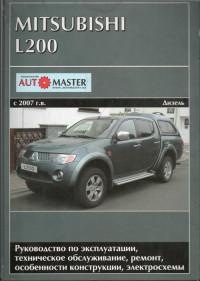
Руководство по эксплуатации, техническому обслуживанию и ремонту автомобиля Mitsubishi L200 с 2007 года выпуска с дизельным двигателем.
- Автор: —
- Издательство: Автомастер
- Год издания: —
- Страниц: 280
- Формат: PDF
- Размер: 42,4 Mb
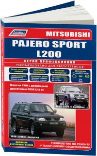
Руководство по техническому обслуживанию и ремонту автомобилей Mitsubishi L200 1996-2006 и Mitsubishi Pajero Sport 1998-2008 годов выпуска с дизельным двигателем объемом 2,5 л.
- Автор: —
- Издательство: Легион-Автодата
- Год издания: —
- Страниц: 448
- Формат: —
- Размер: —


Данная инструкция на русском языке предназначена для автомобиля
Mitsubishi L200 V (2022), описывает принцип работы и основные моменты эксплуатации устройства.
Производитель настойчиво рекомендует перед включением автомобиля
внимательно изучить настоящую инструкцию.
Инструкция для автомобиля
представлена в формате PDF. Все современные браузеры уже поддерживают данный формат и сложностей с открытием файла возникнуть не должно.
Но если открыть инструкцию все же не удается, то необходимо установить на компьютер программу для чтения PDF файлов, например, Acrobat Reader. Если у вас возникли сложности с открытием инструкции на смартфоне под управлением Android, нужно установить, например, Adobe Acrobat Reader.
Оглавление
1
2
3
4
5
6
7
8
9
10
11
12
Краткий обзор / краткое руководство
Общие сведения
Запирание и отпирание дверей
Сиденья и ремни безопасности
Органы управления и контрольно-измерительные приборы
Начало движения и вождение автомобиля
Создание комфортных условий в салоне
Действия в сложных ситуациях
Уход за автомобилем
Техническое обслуживание автомобиля
Технические характеристики
Алфавитный указатель
Комментарии (0)
Комментарии про другие Автомобили
Другие Автомобили Mitsubishi
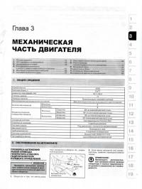
В отличие от системы, описанной в предыдущем разделе, система Super select дополнена межосевым дифференциалом
Установить рычаг управления раздаточной коробкой в положение «2Н». Слить масло из раздаточной коробки. Нанести
Сальники устанавливаются при помощи оправок подходящего размера. Установка выходного вала привода заднего моста, цепи
Последовательность разборки: 1. Винт; 2. прижимная скоба подшипника; 3. Ведущая шестерня раздаточной коробки; 4.
1. Зафиксируйте шток переключения передач (повышенная или пониженная (H-L)) в положении включения повышенной передачи.
Функции датчиков – концевых переключателей и их соответствие разъемам Обозначение Содержание информации, поступающей от
Последовательность разборки: 1. Стопорное кольцо; 2. Шариковый подшипник; 3. Вискомуфта; 4. Выходной вал привода
В раздаточной коробке механизм переключения 2WD/4WD представляет собой 2-конический синхронизатор. Это дает возможность переключать
Измерение производится при помощи отрезков проволоки изготовленной из мягкого припоя (диаметр: 1,0 мм, длина:
Параметр Нормальное значение Предельно допустимое значение Осевой разбег промежуточного вала 0-0,15 мм – Осевой
- Manuals
- Brands
- Mitsubishi MOTORS Manuals
- Automobile
- L200
- Owner’s manual
-
Contents
-
Table of Contents
-
Troubleshooting
-
Bookmarks
Related Manuals for Mitsubishi MOTORS L200
Summary of Contents for Mitsubishi MOTORS L200
-
Page 1
L200 OWNER’S MANUAL L200 — ENGLISH — OKTE17E1… -
Page 2
E09200106706 E09300102174 These serve as reminders to be especially careful. Failure to follow instruc- Thank you for selecting a MITSUBISHI L200 as your new vehicle. Fuel tank capacity 75 litres tions could result in personal injury or damage to your vehicle. -
Page 3
Table of contents Overview/Quick guide General information Locking and unlocking Seat and seat belts Instruments and controls Starting and driving For pleasant driving For emergencies Vehicle care Maintenance Specifications Alphabetical index Declaration of Conformity OKTE17E1… -
Page 4
Instruments and Controls (Driver’s area) Instruments and Controls (Driver’s area) E08500101811 1. Shift paddles* p. 6-31 2. Instruments p. 5-02 3. Headlamp washer switch* p. 5-26 Wiper and washer switch p. 5-23 4. Active stability control (ASC) OFF switch p. 6-60 5. -
Page 5
Instruments and Controls Instruments and Controls E08500101824 1. Audio* p. 7-39 Digital clock* p. 7-102 DISPLAY AUDIO*, MITSUBISHI Multi-Communication Sys- tem*, Smartphone Link Display Audio* Refer to the separate owner’s manual 2. Centre ventilators p. 7-02 3. Heater*/Air conditioning* p. 7-04 4. -
Page 6
Instruments and Controls 1. Front passenger’s airbag indicator* p. 4-25, 4-27 2. Steering wheel height and reach adjustment lever p. 6-07 3. Audio remote control switches* p. 7-28, 7-51 4. Cruise control switch* p. 6-64 5. Supplemental restraint system (SRS) — airbag (for driver’s seat) p. -
Page 7
Instruments and Controls 27. Audio* p. 7-18 7-39 Digital clock* p. 7-102 DISPLAY AUDIO*, MITSUBISHI Multi-Communication Sys- tem*, Smartphone Link Display Audio* Refer to the separate owner’s manual Overview/Quick guide 1-05 OKTE17E1… -
Page 8
Interior Interior E08500201535 1. Inside rear-view mirror p. 6-08 2. Sun visors p. 7-100 Single cab 3. Front seats p. 4-02 4. Head restraints p. 4-05 5. Jack p. 8-13 6. Tools p. 8-13 7. First-aid kit and warning triangle securing bands p. 7-109 8. -
Page 9
Interior 1. Inside rear-view mirror p. 6-08 Club cab 2. Room lamp (front)* p. 7-103, 10-23, 10-29 Map lamps* p. 7-103, 10-23, 10-29 Sunglasses holder* p. 7-105, 7-107 3. Microphone (for Bluetooth ® 2.0 interface)* p. 7-77 4. Room lamp (rear) p. 7-103, 10-23, 10-30 5. -
Page 10
Interior 1. Room lamp (front) p. 7-103, 10-23, 10-29 Double cab Map lamps p. 7-103, 10-23, 10-29 Sunglasses holder p. 7-105, 7-107 2. Microphone (for Bluetooth ® 2.0 interface)* p. 7-77 3. Room lamp (rear) p. 7-103, 10-23,10-30 4. Supplemental restraint system (SRS) — curtain airbag p. 4-24, 4-32 5. -
Page 11
Exterior — front Exterior — front E08500402055 1. Fuel tank filler door p. 2-02 Single cab 2. Locking and unlocking p. 3-15 Keyless entry system p. 3-03 3. Outside rear-view mirrors p. 6-09 4. Side turn-signal lamps p. 5-20, 10-22 5. -
Page 12
Exterior — front 1. Fuel tank filler door* p. 2-02 Club cab 2. Keyless entry system* p. 3-03 Keyless operation system* p. 3-07 Locking and unlocking p. 3-15 3. Side turn-signal lamps (on outside rear-view mirror)* p. 5-20, 10-22 4. Outside rear-view mirrors p. 6-09 5. -
Page 13
Exterior — front 1. Fuel tank filler door* p. 2-02 Double cab 2. Keyless entry system* p. 3-03 Keyless operation system* p. 3-07 Locking and unlocking p. 3-15 3. Side turn-signal lamps (on outside rear-view mirror)* p. 5-20, 10-22 4. Outside rear-view mirrors p. 6-09 5. -
Page 14
Exterior — rear Exterior — rear E08500401843 1. Tyre inflation pressures p. 10-12 Changing tyres p. 8-17 Single cab Tyre rotation p. 10-13 Snow tyres p. 10-14 Tyre chains p. 10-14 2. Tail and stop lamps p. 5-17, 10-22, 10-28 3. -
Page 15
Exterior — rear 1. Tyre inflation pressures p. 10-12 Club cab Changing tyres p. 8-17 Tyre rotation p. 10-13 Snow tyres p. 10-14 Tyre chains p. 10-14 2. Tail and stop lamps p. 5-17, 10-22, 10-28 3. Rear turn-signal lamps p. 5-20, 10-22, 10-28 4. -
Page 16
Exterior — rear 1. Tyre inflation pressures p. 10-12 Double cab Changing tyres p. 8-17 Tyre rotation p. 10-13 Snow tyres p. 10-14 Tyre chains p. 10-14 2. Tail and stop lamps p. 5-17, 10-22, 10-28 3. Rear turn-signal lamps p. 5-20, 10-22, 10-28 4. -
Page 17
Quick guide Around the driver’s seat Refer to “Keyless entry system*” on page Quick guide 3-03. E08500801531 E08500500010 For vehicles equipped with the mirror retrac- Locking and unlocking the tor switch, the outside rear-view mirrors can be folded and extended automatically if you doors press the LOCK switch (1) or UNLOCK E08500601454… -
Page 18
Quick guide 1-Electric remote-controlled Refer to “Outside rear-view mirrors” on Refer to “Engine switch” on page 6-14. outside rear-view mirrors* page 6-09. 3-Combination headlamps 2-Engine switch* Rotate the switch to turn on the lamps. To adjust the mirror position [For vehicles equipped with keyless opera- Type 1 tion system] If you are carrying the keyless operation key,… -
Page 19
Quick guide 3-Turn-signal lever Type 2 3. Securely lock the steering wheel by pull- ing the lever fully upward. The turn-signal lamps flash when the lever is operated. All lamps off 1. Turn-signals With the ignition switch or the 2. Lane-change signals operation mode is in ON, head- lamps, position, tail, licence plate… -
Page 20
Quick guide 6-Electric window control* Refer to “Steering wheel height and reach Vehicles with rain sensor adjustment” on page 6-07. Press the switch down for opening the win- dow, and pull the switch for closing. 5-Wiper and washer switch Except for vehicles equipped with rain Driver’s switch Driver’s switch sensor… -
Page 21
Quick guide 7-Fuel tank filler door release Automatic transmission Sports While depressing the brake ped- lever* Mode 5A/T al, move the selector lever through the gate. Open the fuel tank filler door. E08501001325 The fuel tank filler is located on the rear left Move the selector lever through Selector lever operation side of your vehicle. -
Page 22
Quick guide The following information is included on the multi information display: odometer, tripme- ter, average fuel consumption etc. 1- Engine coolant temperature display ® p. 5-06 2- Selector lever position display* ® p. 6-31 3- Speed limiter display* ® p. 6-71 4- Gearshift indicator* ®… -
Page 23: Table Of Contents
General information Fuel selection………………2-02 Filling the fuel tank…………….2-02 Entering or leaving the vehicle…………2-04 Installation of accessories…………..2-04 Modification/alterations to the electrical or fuel systems….2-06 Genuine parts………………2-06 Safety and disposal information for used engine oil……2-06 Disposal information for used batteries……….2-06 OKTE17E1…
-
Page 24: Fuel Selection
Do not confirm that the diesel preheat indication Be sure to use a MITSUBISHI MOTORS let any other person come near the fuel lamp is off. (Refer to “Diesel preheat indica-…
-
Page 25
Keep the doors and windows closed while refueling the vehicle. If they were open, fuel vapour could get into the cabin. If the fuel cap must be replaced, use only a MITSUBISHI MOTORS genuine part. Fuel tank capacity 75 litres Refueling 3. -
Page 26: Entering Or Leaving The Vehicle
To avoid slipping and damaging the painted turn the key clockwise to lock the fuel surface, do not step on the cover of the side step (A). cap. Installation of accessories E00200302303 Type 2 recommend consult your MITSUBISHI MOTORS Authorized Service Point. 2-04 General information OKTE17E1…
-
Page 27
MITSUBISHI MOTORS, but also a MITSUBISHI MOTORS Authorized Service Point, to check whether the attachment or in- stallation of such parts affects the overall safety of your MITSUBISHI-vehicle. -
Page 28: Modification/Alterations To The Electrical Or Fuel Systems
Use MITSUBISHI MOTORS GENUINE Parts, designed and manufactured to maintain the electrical or fuel systems your MITSUBISHI MOTORS vehicle at top It is illegal to pollute drains, water courses performance. MITSUBISHI MOTORS GEN- and soil. Use authorized waste collection fa-…
-
Page 29
Locking and unlocking Keys………………..3-02 Key number tag……………….3-02 Electronic immobilizer (Anti-theft starting system)……3-03 Keyless entry system*……………..3-03 Keyless operation system*…………..3-07 Doors………………..3-15 Central door locks…………….3-17 Dead Lock System*…………….3-18 “Child-protection” rear doors (Double cab)……..3-20 Rear gate………………… 3-20 Manual window control*…………..3-21 Electric window control*………….. -
Page 30: Keys
• Do not disassemble or modify. 2. Keyless entry key MITSUBISHI MOTORS Authorized Service • Do not excessively bend the key or sub- 3. Keyless operation key ject it to strong impacts.
-
Page 31: Electronic Immobilizer (Anti-Theft Starting System)
“registered” to the To obtain a key, take your vehicle and all re- immobilizer system. maining keys to a MITSUBISHI MOTORS Authorized Service Point. If you need an extra spare key, take your ve- NOTE hicle and all the keys to a MITSUBISHI MOTORS Authorized Service Point.
-
Page 32
Operation of the outside rear- For further information, please contact a view mirrors (Vehicles equip- Press the LOCK switch (1). All the doors will MITSUBISHI MOTORS Authorized Serv- ped with mirror retractor be locked. The turn-signal lamps will blink ice Point. -
Page 33
Functions can be modified as stated below. After pressing the “LOCK” switch to lock MITSUBISHI MOTORS Authorized Please consult a MITSUBISHI MOTORS the doors, if the “LOCK” switch is press- Service Point. Authorized Service Point. ed again twice in a row within about 30 If you replace the battery yourself, refer to •… -
Page 34
MITSUBISHI mark is not facing you when an electric appliance store. you, insert the cloth-covered tip of a you open the key case, the switches may A MITSUBISHI MOTORS Authorized straight blade (or minus) screwdriver in- come out. Service Point can replace the battery for you to the notch in the key case and use it to if you prefer. -
Page 35: Keyless Operation System
Keyless operation system* Keyless operation system* WARNING Keyless entry key + side People with implantable cardiac pace- E00305601871 makers or implantable cardiovascular-de- The keyless operation system allows you to fibrillators should not go near the exterior lock and unlock the doors, start the engine — side transmitters (A) or the interior transmit- and change the operation mode simply by…
-
Page 36
• The keyless operation system is carried have it replaced a MITSUBISHI MOTORS together with a communications device Authorized Service Point. such as a cellular phone or radio set, or Refer to “Procedure for replacing the key… -
Page 37
Keyless operation system* Operating range for starting the NOTE NOTE engine and changing the opera- If the keyless operation key battery is wear- Locking and unlocking operates only when ing out or there are strong electromagnetic you press a door switch that detects the key- tion mode waves or noise present, the operating range less operation key. -
Page 38
The time between unlocking and automatic locking can be adjusted. Please consult a position at this time, the room lamp will turn MITSUBISHI MOTORS Authorized Serv- To operate using the keyless on for 15 seconds. The turn-signal lamps will ice Point. -
Page 39
To lock/unlock without using NOTE Locking and unlocking the door the keyless operation function Turning the emergency key in the forward di- MITSUBISHI MOTORS Authorized Serv- rection locks the door, and turning it in the ice Point. E00306000165 Emergency key •… -
Page 40
For further in- formation, please contact a MITSUBISHI MOTORS Au- thorized Service Point. Even if you have the keyless operation key within the engine start operating range, if the key… -
Page 41
Blinks. The battery in the keyless operation key Replace the battery as soon as pos- has worn out. sible at a MITSUBISHI MOTORS Authorized Service Point. Illuminates. A power supply is not switched over from Please confirm that the keyless op- OFF because the keyless operation key in eration key is in the vehicle. -
Page 42
(intermittent sounds) Immediately stop the vehicle in a Inner buzzer sounds safe place contact (continuous sounds). MITSUBISHI MOTORS Authorized Service Point. Blinks. Outer buzzer sounds Keyless operation key When the operation mode is in OFF with Remove the keyless operation key approximately 3 sec- reminder. -
Page 43: Doors
Put the operation mode in OFF and er (Anti-theft starting system). then start the engine again. If the warning is not cancelled, contact a MITSUBISHI MOTORS Author- ized Service Point. Inner buzzer sounds. Steering wheel lock. Blinks. Steering wheel does not unlock.
-
Page 44
Doors 1- Lock NOTE NOTE 2- Unlock The driver’s door can be opened without us- The driver’s door cannot be locked using the ing the lock knob by pulling on the inside inside lock knob while the driver’s door is NOTE door handle. -
Page 45: Central Door Locks
Central door locks Central door locks WARNING NOTE When opening the rear door, confirm that If the vehicle is equipped with the keyless E00300803306 the occupant of the front seat has taken operation system, the driver’s door can be NOTE off the seat belt before opening the rear locked or unlocked with the emergency key.
-
Page 46: Dead Lock System
The central door lock system is broken hicle is shipped from the factory. If you wish sensitive unlock mechanism) down. to activate or deactivate these functions, please contact a MITSUBISHI MOTORS All of the doors lock automatically when the NOTE Authorized Service Point. vehicle…
-
Page 47
(C). For details, please The UNLOCK switch (B) on the key is contact a MITSUBISHI MOTORS Author- pressed. ized Service Point. The driver’s or front passenger’s door… -
Page 48: Child-Protection» Rear Doors (Double Cab)
“Child-protection” rear doors (Double cab) To open After setting the Dead Lock System, reach A lever is provided on each rear door. into the vehicle through a window and con- If the lever is set to the locked position, the firm that you cannot unlock the doors using rear door cannot be opened using the inside Lift up the handle and lower the rear gate.
-
Page 49: Manual Window Control
Manual window control* To swing down 2. Remove the wire (A) on one side while CAUTION aligning the hole in the wire with the Never close the rear gate with the wire left The rear gate can be swung down in two hook (B).
-
Page 50
Electric window control* Electric window control switch Press the switch down for opening the win- WARNING dow, and pull up the switch for closing it. E00302303161 The child may tamper with the switch at Each door window opens or closes while the the risk of its hands or head being trap- corresponding switch is operated. -
Page 51
Electric window control* Safety mechanism (driver’s To unlock, press it once again. NOTE window only) The safety mechanism can be activated if the driving conditions or other circumstances E00302502108 When the door window is automatically cause the driver’s door window to be subjec- closed by pulling up the switch fully, if a ted to a physical shock similar to that caused by a trapped hand or head. -
Page 52
OKTE17E1… -
Page 53
Seat and seat belts Seat adjustment………………. 4-02 Front seats………………. 4-02 Rear seat (Club cab and Double cab)*……….4-04 Head restraints*……………….4-05 Seat belts………………… 4-07 Pregnant women restraint…………..4-10 Seat belt pretensioner system and force limiter system*….4-10 Child restraint………………4-11 Seat belt inspection…………….4-23 Supplemental restraint system (SRS)-airbag*…….. -
Page 54: Seat Adjustment
Seat adjustment Seat adjustment WARNING CAUTION To minimize the risk of personal injury in If your vehicle is equipped with the rear E00400301887 the event of a collision or sudden braking, seat, when sliding or reclining the seat rear- Adjust the driver’s seat so that you are com- the seatbacks should always be in the al- ward, pay careful attention to the rear seat fortable and that you can reach the pedals,…
-
Page 55
Front seats 3- To adjust seat cushion height (driver’s 4- To adjust seat cushion angle 3 (LO) Heater low (to keep the seat side only of Club cab and Double cab) Operate the switch as indicated by the warm). Turn the dial and adjust the seat cushion arrows and adjust the seat cushion angle height to the desired position. -
Page 56: Rear Seat (Club Cab And Double Cab)
Rear seat (Club cab and Double cab)* Folding the seatback forward Securely retain the seat cushion by hooking CAUTION the retaining band (A) onto the head restraint (Double cab) If water or any other liquid is spilled on the (B) of the rear seat. seat, allow it to dry thoroughly before at- E00401601467 Pull up the band on the top of the seatback…
-
Page 57: Head Restraints
Head restraints* Rear centre seat To adjust height NOTE To reduce the risk of injury in an accident, Do not climb or sit on the armrest. Doing so pull up the head restraint to the locked posi- could damage the armrest. Front seats The top surface of the armrest contains a cup tion.
-
Page 58
Head restraints* The head restraint stalk with the adjustment WARNING notches (B) must be installed in the hole with could otherwise be suffered as the result the adjusting knob (A) (except head restraints of an impact. (Double cab) of the outer seat). CAUTION The shape and size of the head restraint dif- fers according to the seat. -
Page 59: Seat Belts
Seat belts Seat belts WARNING NOTE The seat belt will provide its wearer with You can check if the belt locks by pulling it E00404802089 maximum protection if the recliner seat- forward quickly. To protect you and your passengers in the back is placed in fully upright position.
-
Page 60
Seat belts WARNING NOTE This warning lamp shows the case of the left-hand drive vehicles. Never wear the lap portion of the belt If the seat belt (A) or ring (B) becomes dirty, across your abdomen. During accidents it the belt may not retract smoothly. If the seat can press sharply against the abdomen belt and ring are dirty, clean them with a If the ignition switch is turned to the “ON”… -
Page 61
Seat belts Adjustable seat belt anchor If the vehicle is driven with the seat belt still NOTE unfastened, the warning lamps come on for (front seats of Club cab and When luggage is placed on the front passen- approximately another 30 seconds. (This illu- Double cab) ger seat, a sensor in the seat cushion may, mination happens only the first time the vehi-… -
Page 62: Pregnant Women Restraint
(ve- MITSUBISHI MOTORS guidelines. It is Seat belts work for everyone, including hicles equipped with SRS side airbags and important to do so because the work could pregnant women.
-
Page 63: Child Restraint
Child restraint Force limiter system WARNING WARNING E00406001280 When attaching a child restraint system Extreme Hazard! In the event of a collision, each force limiter to the rear seat, adjust the front seat to NEVER use a rearward facing child re- system will effectively absorb the load ap- prevent the front seatbacks from touching straint on a seat protected by an ACTIVE…
-
Page 64
Child restraint Instruction: WARNING WARNING For small infants, an infant carrier A REARWARD FACING CHILD RE- When installing a child restraint system, should be used. For small children STRAINT must NOT be used in the front refer to the instructions provided by the passenger seat if the front passenger’s air- manufacturer of the restraint system. -
Page 65
Child restraint Older children E00406701418 Children who have outgrown the child re- straint system should be seated in the seat and wear combination lap shoulder belt. The lap portion of the belt should be snug and positioned low on the abdomen so that it is below the top of the hip-bone. -
Page 66
Child restraint Suitability for various ISOFIX positions (Double cab) E00411401989 Vehicle ISO- UN-R44 Approval FIX positions Mass group Size class Fixture Recommended Child Restraint Systems* Rear outboard Carrycot ISO/L1 — — ISO/L2 — — 0 — Up to 10 kg ISO/R1 —… -
Page 67
KIDFIX: MZ314804 E1-04301198 36 kg : MITSUBISHI MOTORS Europe B.V. reserves the right to changes without any prior announcement. For detailed information, consult your MITSUBISHI MOTORS Authorized Service Point. CAUTION When installing a child restraint system, remove the head restraint from the seat. -
Page 68
36 kg KIDFIX: MZ314804 E1-04301198 : MITSUBISHI MOTORS Europe B.V. reserves the right to changes without any prior announcement. For detailed information, consult your MITSUBISHI MOTORS Authorized Service Point. CAUTION When installing a child restraint system, remove the head restraint from the seat. -
Page 69
KIDFIX: MZ314804 E1-04301198 : MITSUBISHI MOTORS Europe B.V. reserves the right to changes without any prior announcement. For detailed information, consult your MITSUBISHI MOTORS Authorized Service Point. : With front passenger’s airbag deactivated by means of front passenger’s airbag ON-OFF switch. -
Page 70
E1-04301146 MZ314393 : MITSUBISHI MOTORS Europe B.V. reserves the right to changes without any prior announcement. For detailed information, consult your MITSUBISHI MOTORS Authorized Service Point. : With front passenger’s airbag deactivated by means of front passenger’s airbag ON-OFF switch. -
Page 71
KIDFIX: MZ314804 E1-04301198 : MITSUBISHI MOTORS Europe B.V. reserves the right to changes without any prior announcement. For detailed information, consult your MITSUBISHI MOTORS Authorized Service Point. : With front passenger’s airbag deactivated by means of front passenger’s airbag ON-OFF switch. -
Page 72
Child restraint CAUTION When installing a child restraint system, remove the head restraint from the seat. Child restraint system with support leg can not be suitable on the rear centre seat. When installing a child restraint system (Mass group II & III) on the front passenger seat, please move the seatbacks position to 2 steps rearward from upright position. -
Page 73
Child restraint Installing a child restraint sys- WARNING Type 2 (i-size marking) tem to the lower anchorage Child restraint anchorages are designed (ISOFIX child restraint mount- to withstand only those loads imposed by correctly fitted child restraints. Under no ings) and tether anchorage circumstances are they to be used for (Double cab) adult seat belts, harnesses, or for attach-… -
Page 74
Child restraint To install port leg at the stable position on the 5. Tip the armrest forward. Open the two floor. fasteners (D) that are located in the 1. Remove any foreign material in or If your child restraint system with a teth- space where the armrest are stowed. -
Page 75: Seat Belt Inspection
Seat belt inspection Installing a child restraint sys- WARNING tem to a 3-point type seat belt For some types of child restraint, the lock- (with emergency locking mech- ing clip (A) should be used to help avoid personal injury during a collision or sud- anism) den manoeuvre.
-
Page 76: Supplemental Restraint System (Srs)-Airbag
Supplemental restraint system (SRS)-airbag* WARNING WARNING The SRS driver’s and front passenger’s air- We recommend you to have all seat belt Do not insert any foreign objects (pieces bags are designed to supplement the primary assemblies including retractors and at- of plastic, paper clips, buttons, etc.) in the protection of the driver and front passenger taching hardware inspected after any col-…
-
Page 77
Supplemental restraint system (SRS)-airbag* The SRS curtain airbags (if so equipped) are 7. Curtain airbag modules* designed to supplement properly worn seat belts and provide the driver and passengers Only when the ignition switch or the opera- on the front seat and rear outboard seat with tion mode is under the following conditions, protection against head injuries by deploying the airbags will operate. -
Page 78
Supplemental restraint system (SRS)-airbag* CAUTION WARNING Airbags inflate at an extremely rapid speed. Older children should be seated, properly In certain situations, contact with inflating wearing the seat belt, with an appropriate airbags can result in abrasions, bruises, light booster seat if needed. cuts, and the like. -
Page 79
Supplemental restraint system (SRS)-airbag* Front passenger’s airbag indi- NOTE WARNING cator (Club cab and Double The labels may be in different positions de- Do not fit any accessory that makes the cab) pending on the vehicle model. indication lamp impossible to see, and do not cover the indication lamp with a stick- E00410201430 er. -
Page 80
We recommend you to AHA109190 have the system inspected by a MITSUBISHI MOTORS Authorized The front passenger’s airbag is now deactiva- Service Point. ted and will not deploy until switched on •… -
Page 81
Supplemental restraint system (SRS)-airbag* Driver’s knee airbag system* Deployment of front airbags The front airbags and driver’s knee airbag will deploy if the severity of impact is above and driver’s knee airbag E00412401263 the designed threshold level, comparable to The driver’s knee airbag is located under the E00407502814 an approximately 25 km/h (16 mph) collision steering wheel. -
Page 82
Supplemental restraint system (SRS)-airbag* The front airbags and driver’s Because the front airbags and driver’s knee Because the front airbags and driver’s knee knee airbag MAY NOT DE- airbag do not protect the occupant in all types airbag do not protect the occupant in all types PLOY when…… -
Page 83
Such objects could prevent the you to have the entire airbag system in- driver’s knee airbag from inflating nor- spected by a MITSUBISHI MOTORS mally or could be propelled to cause seri- Authorized Service Point. ous injury if the airbag inflates. -
Page 84
Supplemental restraint system (SRS)-airbag* The side airbags and curtain Curtain airbag system* The side airbag is designed to inflate only on airbags ARE DESIGNED TO the side of the vehicle that is impacted, even E00409101989 DEPLOY when… with no passenger in the front seat. The curtain airbags are contained in the front pillars and roof side rail. -
Page 85
Supplemental restraint system (SRS)-airbag* The side airbags and curtain The seat belts in your vehicle are your pri- 1. Side impacts in an area away from the airbags ARE NOT DESIGNED mary means of protection in a collision. The passenger compartment TO DEPLOY when… -
Page 86
Supplemental restraint system (SRS)-airbag* WARNING Because the side airbags and curtain airbags Do not allow any rear seat occupant to do not protect the occupant in all types of hold onto the seatback of either front seat, collisions, be sure to always properly wear in order to reduce risk of injury from the your seat belts. -
Page 87
We recommend work around and on the side airbags and curtain airbags system to WARNING WARNING be done by a MITSUBISHI MOTORS Authorized Service Point. If any of the following conditions occur, We recommend any maintenance per- there may be a problem with the SRS air-… -
Page 88
Supplemental restraint system (SRS)-airbag* NOTE If your vehicle has to be scrapped, do this in line with the local legislation and contact a MITSUBISHI MOTORS Authorized Serv- ice Point to safely dismantle the airbag sys- tem. 4-36 Seat and seat belts… -
Page 89
Instruments and controls Instruments………………5-02 Multi-information display…………..5-02 Indication and warning lamps (multi information display)….5-12 Indication lamps………………5-13 Warning lamps………………5-15 Combination headlamps and dipper switch……..5-17 Headlamp levelling switch…………..5-19 Turn-signal lever…………….. 5-20 Hazard warning flasher switch…………5-21 Fog lamp switch*…………….5-22 Wiper and washer switch………….. -
Page 90: Instruments
Instruments 1- Engine coolant temperature display Instruments ® p. 5-06 E00500102883 2- Selector lever position display* ® p. 6-31 3- Speed limiter display* ® p. 6-71 4- Gearshift indicator* ® p. 6-26 5- Fuel remaining display ® p. 5-07 6- Frozen road warning* ® p. 5-06 7- Information display ®…
-
Page 91
Multi-information display Information display E00528201313 Each time you lightly press the multi information display switch (A), the display switches in the following order. 1- Odometer ® p. 5-04 5- Driving range display ® p. 5-05 8- Outside temperature display* ® p. 5-06 2- Tripmeter 6- Average fuel consumption display ®… -
Page 92
Multi-information display NOTE When the ignition switch or the operation mode is OFF, the driving range display, average fuel consumption display and outside temperature display are not displayed. While driving, the service reminder is not displayed even if you operate the multi information display switch. Odometer Meter illumination control Example… -
Page 93
Multi-information display NOTE NOTE NOTE You can adjust to 8 different levels respec- When you refuel, the driving range display The average fuel consumption display can tively for when the position lamps are illu- is updated. be reset separately for the auto reset mode minated and when they are not. -
Page 94
Multi-information display Frozen road warning* Engine coolant temperature NOTE display E00533401036 When the ignition switch or the operation If the outside air temperature drops below ap- mode is ON again, the accumulated time E00533801072 prox. 3 °C (37 °F), the alarm sounds and the This indicates the engine will be reset. -
Page 95
NOTE periodic inspection time can be modified. To modify the display settings, have it adjus- It may take several seconds to stabilise the ted at a MITSUBISHI MOTORS Authorized display after refilling the tank. Service Point. CAUTION If fuel is added with the ignition switch or… -
Page 96
Please consult to make the spanner mark start flashing. performed. MITSUBISHI MOTORS Authorized Inspections and maintenance must be per- (If there is no operation for about 10 sec- Service Point. formed to prevent accidents and malfunc- onds with flashing, the display will re- 3. -
Page 97
Turn the ignition switch from the If you accidentally reset the display, consult 2. Each time you press the multi informa- “ACC” or “LOCK” position to the “ON” a MITSUBISHI MOTORS Authorized Serv- tion display switch for 2 seconds or position. ice Point. -
Page 98
Multi-information display When the engine switch or the operation 1. When you lightly press the multi infor- NOTE mode is in the following conditions, the mation display switch a few times, the The memory of the unit setting is erased if average fuel consumption display is au- information display switches to the aver- the battery is disconnected, and it returns au-… -
Page 99
Multi-information display NOTE The temperature value on air conditioner panel is switched in conjunction with outside temperature display unit of the multi infor- mation display. However, “°C” or “°F” are not shown to temperature display of an air conditioner. Instruments and controls 5-11 OKTE17E1… -
Page 100: Indication And Warning Lamps (Multi Information Display)
Indication and warning lamps (multi information display) Indication and warning lamps (multi information display) E00501504093 Type 1 Type 2 1. Front fog lamp indication lamp* 7. Lane departure warning (LDW) system 15. A/T (automatic transmission) fluid tem- ® p. 5-13 ON indication lamp* ®…
-
Page 101: Indication Lamps
Indication lamps 23- Seat belt reminder/warning lamp 27- Supplement Restraint System (SRS) 32- 2WD/4WD operation indication lamp* ® p. 4-08 warning lamp ® p. 4-35 ® p. 6-42 28- Brake warning lamp ® p. 5-15 33- Low-range indication lamp* ® p. 6-42 24- Anti-lock brake system (ABS) warning lamp ®…
-
Page 102
Indication lamps Position lamp indication lamp* Fuel filter indication lamp CAUTION E00508901301 E00509901353 If the diesel preheat indication lamp comes This indication lamp illumi- This indication lamp illumi- on after the engine is started, the engine nates while the position nates when ignition… -
Page 103: Warning Lamps
Warning lamps Check engine warning lamp Warning lamps CAUTION E00502603137 In the situations listed below, brake perform- E00502400147 This lamp is a part of an on- ance may be compromised or the vehicle board diagnostic system Brake warning lamp may become unstable if brakes are applied which monitors the emis- suddenly;…
-
Page 104
Immediately park your vehicle in a safe level. The oil level must be checked using MITSUBISHI MOTORS Authorized Serv- place and we recommend you to have it the dipstick. ice Point as soon as possible. checked. Accelerator pedal and brake pedal response… -
Page 105: Combination Headlamps And Dipper Switch
Combination headlamps and dipper switch Type 1 Type 2 refer to “Refill capacities” on page 11-18. Combination headlamps Rotate the switch to turn on the lamps. Rotate the switch to turn on the lamps. and dipper switch E00506004080 Headlamps NOTE Do not leave the lamps on for a long time while the engine is stationary (not running).
-
Page 106
For further information, we recommend you Do not cover the sensor (A) for the automat- to consult a MITSUBISHI MOTORS Au- [For vehicles equipped with keyless op- ic on/off control by affixing a sticker or label thorized Service Point. -
Page 107: Headlamp Levelling Switch
Headlamp levelling switch Dipper (High/Low beam If the driver’s door is opened when the key is NOTE in the “LOCK” or “ACC” position or re- change) The high-beams can also flash when the moved from the ignition switch while the lamp switch is OFF.
-
Page 108: Turn-Signal Lever
Turn-signal lever Set the switch (referring to the following ta- Switch position 4- Driver + Full luggage Switch posi- “0” “2” ble) to the appropriate position according to tion loading the number of people and the load in the ve- Vehicles with high in- hicle.
-
Page 109: Hazard Warning Flasher Switch
3-flash function can be adjusted. • Changing of the tone of a sounding buz- zer as the turn-signal lamps flash. For further information, we recommend you to consult a MITSUBISHI MOTORS Au- thorized Service Point. Instruments and controls 5-21 OKTE17E1…
-
Page 110: Fog Lamp Switch
Fog lamp switch* Turn the knob once in the “ON” direction to Fog lamp switch* NOTE turn on the front fog lamps. Turn the knob The front fog lamps are automatically turned E00506700089 once more in the “ON” direction to turn on off when the headlamps or tail lamps are Front fog lamp switch* the rear fog lamp.
-
Page 111: Wiper And Washer Switch
Slow For further information, we recommend you Fast to consult a MITSUBISHI MOTORS Au- thorized Service Point. Misting function Move the lever in the direction of the arrow and release, to operate the wipers once.
-
Page 112
Wiper and washer switch Use this function when you are driving in CAUTION AUTO- Auto-wiper control mist or drizzle. Rain sensor With the ignition switch or the operation The wipers will automatically mode in ON and the lever in the “AUTO” operate depending on the degree position, the wipers may automatically oper- of wetness on the windscreen. -
Page 113
For further information, we recommend you mode is in the “ON” or “ACC” position. The to consult a MITSUBISHI MOTORS Au- thorized Service Point. wipers will continue to operate while the lev- •… -
Page 114
Wiper and washer switch Windscreen washer Headlamp washer switch* The wipers will operate once if the lever is moved to the “AUTO” position and the knob E00507202421 E00510101629 (C) is turned in the “+” direction when the ig- The washer fluid will be sprayed onto the The headlamp washer can be operated with nition switch is in the “ON”… -
Page 115: Rear Window Demister Switch
Rear window demister switch Precautions to observe when Periodically check the level of washer The indication lamp (A) will illuminate while fluid in the reservoir and refill if re- the demister is on. using wipers and washers quired. E00507601473 During cold weather, add a recommen- If the moving wipers become blocked Type 1 ded washer solution that will not freeze…
-
Page 116: Horn Switch
Horn switch Enable automatic rear window demister Horn switch NOTE If the outside air temperature drops be- On vehicles equipped with heated mirrors, E00508001823 low approx. 3 °C (37 °F), the rear win- when the rear window demister switch is Press the steering wheel on or around the dow demister operates once automatical- pressed, the outside rear-view mirrors are…
-
Page 117
Starting and driving Economical driving…………….6-02 Power steering system……………..6-59 Driving, alcohol and drugs…………..6-02 Active Stability & Traction Control (ASTC)*……..6-59 Safe driving techniques……………6-03 Trailer Stability Assist (TSA)…………. 6-63 Running-in recommendations…………. 6-04 Cruise control*………………6-63 Parking brake………………6-05 Speed Limiter………………6-69 Parking………………..6-06 Lane Departure Warning (LDW)*…………6-76 Steering wheel height and reach adjustment……..6-07 Rear-view camera*……………. -
Page 118: Economical Driving
Economical driving City traffic Cargo loads Economical driving E00600102318 Frequent starting and stopping increases the Do not drive with unnecessary articles in the For economical driving, there are some tech- average fuel consumption. Use roads with luggage compartment. Especially during city nical requirements that have to be met.
-
Page 119: Safe Driving Techniques
Safe driving techniques Seat belts Carrying children in the vehi- Your driving ability can be seriously im- paired even with blood alcohol levels far be- low the legal minimum. If you have been Before starting the vehicle, make sure that drinking, don’t drive.
-
Page 120: Running-In Recommendations
Running-in recommendations Running-in recommendations E00600404070 During the running-in period for the first 1,000 km (620 miles), it is advisable to drive your new vehicle using the following precautions as a guideline to aid long life as well as future economy and performance. Do not race the engine at high speeds.
-
Page 121: Parking Brake
Parking brake Vehicles with A/T Speed limit Shift point Vehicles with Easy select 4WD Vehicles with Super select 4WD II 2H, 4H 2H, 4H, 4HLc 4LLc 15 km/h (9 mph) 15 km/h (9 mph) 5 km/h (3 mph) 20 km/h (12 mph) 5 km/h (3 mph) gear 35 km/h (22 mph)
-
Page 122: Parking
Parking To apply NOTE CAUTION If the parking brake does not hold the vehi- If the brake warning lamp does not extin- cle stationary after the foot brake is released, guish when the parking brake is fully re- have your vehicle checked immediately. leased, the brake system may be abnormal.
-
Page 123: Steering Wheel Height And Reach Adjustment
Steering wheel height and reach adjustment Parking on a downhill slope Where you park NOTE Turn the front wheels towards the kerb and If your vehicle is equipped with A/T, be sure WARNING move the vehicle forward until the kerb side to apply the parking brake before moving se- lector lever to the “P”…
-
Page 124: Inside Rear-View Mirror
Inside rear-view mirror To adjust the vertical mirror Inside rear-view mirror Type 1 position E00600802126 Adjust the rear-view mirror only after mak- It is possible to move the mirror up and down ing any seat adjustments so you have a clear to adjust its position.
-
Page 125: Outside Rear-View Mirrors
Outside rear-view mirrors To reduce the glare When the headlamps of the vehicles behind Outside rear-view mirrors you are very bright, the reflection factor of E00600900628 Type 1 the rear-view mirror is automatically changed To adjust the mirror position to reduce the glare. The lever (A) at the bottom of the mirror can be used to adjust the mirror to reduce the E00601001971…
-
Page 126
Outside rear-view mirrors Manual outside rear-view mir- Retracting and extending the 1. Place the lever (A) to the same side as rors* the mirror whose adjustment is desired. outside mirrors Adjust the mirror surface by hands as indica- E00601101930 The outside mirror can be folded in towards ted by the arrows. -
Page 127
Outside rear-view mirrors Except for vehicles equipped After turning the ignition switch to the NOTE with the mirror retractor switch “LOCK” position or putting the operation Be careful not to get your hands trapped mode in OFF, it is possible to retract and ex- Push the mirror towards the back of the vehi- while a mirror is moving. -
Page 128
After pressing the “UNLOCK” switch to un- Functions can be modified as stated below. lock the doors, if the “UNLOCK” switch is Please consult a MITSUBISHI MOTORS pressed again twice in a row within about 30 Authorized Service Point. seconds, the outside rear-view mirrors will •… -
Page 129: Ignition Switch
“ACC” position and keep it depressed erated. For further information, we recommend you until it is turned to the “LOCK” position, and to consult a MITSUBISHI MOTORS Au- START remove it. thorized Service Point. The starter motor operates. After the engine…
-
Page 130: Engine Switch
Do not turn the key to the “START” position flashing orange. Immediately contact a while the engine is running. Doing so could MITSUBISHI MOTORS Authorized Serv- damage the starter motor. ice Point. If the engine switch operation is not smooth…
-
Page 131
The ACC power auto-cutout function can • change, the keyless operation key may have be deactivated. worn out. For details, we recommend you to consult a MITSUBISHI MOTORS Authorized Service Point. Starting and driving 6-15 OKTE17E1… -
Page 132: Steering Wheel Lock
Steering wheel lock Operation mode OFF reminder Steering wheel lock CAUTION system Remove the key when leaving the vehicle. E00601501918 In some countries, it is prohibited to leave E00632201083 Except for vehicles equipped with the key- the key in the vehicle when parked. less operation system To lock For vehicles equipped with the keyless op-…
-
Page 133: Starting And Stopping The Engine
ACC or ON. stop the vehicle in a safe place and contact • On vehicles with A/T, put the operation your nearest a MITSUBISHI MOTORS Au- WARNING mode in ON. thorized Service Point. Never run the engine in a closed or poorly…
-
Page 134
Starting and stopping the engine the gearshift lever in the “N” (Neutral) CAUTION WARNING position. Do not run the engine at high speeds or drive Never run the engine in a closed or poorly On vehicles equipped with A/T, make the vehicle at high speeds until the engine ventilated area any longer than is needed sure the selector lever is in the “P”… -
Page 135
Starting and stopping the engine On vehicles equipped with A/T, make NOTE For vehicles equipped with the keyless op- sure the selector lever is in the “P” eration system When the engine has not been started within (Park) position. 1. Fasten the seat belt. approximately 5 seconds after the diesel pre- heat indication lamp went out, return the ig- 2. -
Page 136
Starting and stopping the engine 2. Fully engage the parking brake while de- NOTE For vehicles equipped with the keyless op- pressing the brake pedal. eration system Minor noises may be heard on engine start- 3. On vehicles with M/T, press the engine up. -
Page 137: Diesel Particulate Filter (Dpf)
Diesel particulate filter (DPF) Keyless operation key remind- Remove the keyless operation key from the Diesel particulate filter key slot after starting the engine or changing (DPF) the operation mode. E00633001059 E00619801457 The diesel particulate filter (DPF) is a device that captures most of the particulate matter (PM) in the exhaust emissions of the diesel engine.
-
Page 138: Turbocharger Operation
E00611200083 CAUTION If the DPF warning lamp subsequently stays Do not run the engine at high speeds (for ex- on, contact your MITSUBISHI MOTORS ample, by revving it or by accelerating rap- idly) immediately after starting it. Authorized Service Point.
-
Page 139: Auto Stop & Go (As&G) System
Auto Stop & Go (AS&G) system* Turbocharger Auto Stop & Go (AS&G) Refer to “To deactivate” on page 6-26. When the AS&G system will operate, the in- system* The turbocharger increases engine power by dication lamp will turn on to inform the driv- pushing large amounts of air into the engine’s E00627401104 cylinders.
-
Page 140
Auto Stop & Go (AS&G) system* 3. Release the clutch pedal. The engine will CAUTION NOTE stop automatically. • Do not depress the accelerator pedal to • Driver’s door is opened. race the engine while the vehicle is stop- • Bonnet is open. -
Page 141
Auto Stop & Go (AS&G) system* NOTE NOTE NOTE • Electric power consumption is high, such If the windows become fogged up each time If the engine does not restart automatically as when the rear window demister or oth- the engine is stopped, we recommend you to or if the engine stalls, the charge warning er electrical components are operating or deactivate the AS&G system by pressing the… -
Page 142
In the following cases, the engine will not recommend consult restart automatically. • While the engine is stopped automatical- MITSUBISHI MOTORS Authorized Service ly, the “AS&G OFF” switch is pressed to Point. deactivate the “AS&G” system. • Bonnet is opened. -
Page 143: Manual Transmission
Manual transmission* Moving the gearshift lever to Manual transmission* NOTE the “R” (Reverse) position During cold weather, shifting may be diffi- E00602002005 cult until the transmission lubricant has E00615401211 The shift pattern is shown on the gearshift Depress and hold the gearshift lever to the warmed up.
-
Page 144: Automatic Transmission Sports Mode 5A/T
Automatic transmission Sports Mode 5A/T 2WD models Automatic transmission Shift point Speed limit Sports Mode 5A/T 2H, 4H Shift point Speed limit 165 km/h 70 km/h gear 30 km/h (19 mph) E00603201935 gear (102 mph) (43 mph) NOTE 60 km/h (37 mph) gear Vehicles with Super select 4WD II During running-in period or immediately af-…
-
Page 145
Immedi- WARNING ately have your vehicle checked by a Always depress the brake pedal when MITSUBISHI MOTORS Authorized Service shifting the selector lever into a gear from Point. the “P” (PARK) or “N” (NEUTRAL) po- If you need to move the vehicle, shift the se- sition. -
Page 146
Automatic transmission Sports Mode 5A/T 3. Insert a straight blade (or minus) screw- 5. Insert a straight blade (or minus) screw- 4. Insert a straight blade (or minus) screw- driver with a cloth over its tip into notch driver in the shiftlock release hole (B). driver in the shift-lock release hole (A). -
Page 147
Automatic transmission Sports Mode 5A/T “D” DRIVE Selector lever position display CAUTION This position is used for most city and high- E00603501954 Never shift into the “P” (PARK) or “R” When the ignition switch is turned to the way driving. The transmission will automati- (REVERSE) position while the vehicle is in “ON”… -
Page 148
Automatic transmission Sports Mode 5A/T — (SHIFT DOWN) NOTE NOTE The transmission shifts down by one gear If your vehicle is equipped with shift pad- To maintain good running performance, the with each operation. dles, you can shift into sports mode with transmission may refuse to perform an up- shift paddles when the selector lever is in the shift when the selector lever or the shift pad-… -
Page 149
Immedi- ately have the vehicle inspected at a MITSUBISHI MOTORS Authorized Serv- ice Point. through Starting and driving 6-33… -
Page 150
Automatic transmission Sports Mode 5A/T When the A/T (automatic trans- CAUTION CAUTION mission) fluid temperature If the lamp comes on, reduce the engine Operating the accelerator pedal while the warning lamp comes on speed and stop the vehicle in a safe area. other foot is resting on the brake pedal will Then set the selector lever to “P”… -
Page 151: Easy Select 4Wd
Easy select 4WD* NOTE NOTE NOTE In sports mode, downshifts do not take place On a slope, be sure to apply the parking When the selector lever position display in when the accelerator is depressed all the way brake before moving the selector lever to the the instrument panel blinks, it means that to the floor.
-
Page 152
Easy select 4WD* Drive mode-selector position Drive mode-selector operation : Illuminate : Remain off and 2WD/4WD operation indi- E00641200024 The drive mode is shown on the drive mode- cation lamp CAUTION selector. E00641100049 The “4L” range gives maximum torque for Drive mode-se- Indication Driving… -
Page 153
Easy select 4WD* Procedure To shift from Vehicles with manual transmission Vehicles with automatic transmission The drive mode-selector can be operated while the The drive mode-selector can be operated while the ve- vehicle is either moving or stationary. hicle is either moving or stationary. When the vehicle is not in motion, shift the selector When the vehicle is not in motion, shift the gearshift lever to the “N”… -
Page 154
Easy select 4WD* “2H” ↔ “4H” CAUTION NOTE Do not operate the drive mode-selector Drive mode-selector Indication lamp • Keep the steering wheel in the straight while the rear wheels of the vehicle are slip- ahead position while making range selec- position ping on snow or ice. -
Page 155
Restart the engine. The lamp should resume normal operation. If the lamps continue to blink, have the vehicle checked by a MITSUBISHI MOTORS Authorized Serv- ice Point as soon as possible. Starting and driving 6-39… -
Page 156: Super Select 4Wd Ii
Super select 4WD II* Drive mode-selector position Super select 4WD II* Drive mode-selec- Indication Driving and 2WD/4WD operation indi- tor position lamp conditions E00605701253 cation lamp When Shifting to rear-wheel drive or 4-wheel drive driving up can be made by operating the drive mode-se- E00605801371 down lector (A).
-
Page 157
Super select 4WD II* Drive mode-selector operation : Turn the drive mode-selector CAUTION : Turn the drive mode-selector while hold- E00605901402 Do not drive your vehicle in the “4HLc” or ing it down The drive mode is shown on the drive mode- “4LLc”… -
Page 158
Super select 4WD II* Procedure To shift from Vehicles with manual transmission Vehicles with automatic transmission gear noise may be generated, with a possible failure to 4LLc 4HLc shift into a proper gear. 2WD/4WD operation indica- NOTE NOTE tion lamp and low-range indi- Setting of the drive mode-selector between When the drive mode-selector is set be- cation lamp… -
Page 159
Super select 4WD II* “4H” ↔ “4HLc” “4HLc” ↔ “4LLc” When the ignition switch is in the “ON” posi- tion or the operation mode is put in ON, the Drive mode-selector Drive mode- 2WD/4WD operation indication lamp and the Indication lamp position selector posi- Indication lamp… -
Page 160
Super select 4WD II* NOTE NOTE NOTE When the drive mode-selector is set between When parking, apply the parking brake be- The Active Stability Control function is sus- “2H”, “4H” and “4HLc”, the front wheel fore stopping the engine and make sure that pended while “4LLc”… -
Page 161: Rear Differential Lock
Restart the engine. The lamp should resume normal operation. If the lamps con- tinue to blink, have the vehicle checked by a MITSUBISHI MOTORS Authorized Serv- ice Point as soon as possible. CAUTION Operate the rear differential switch after the wheels are stopped.
-
Page 162
Rear differential lock* NOTE The opera- Rear differential lock indi- Super select 4WD II tion state of cation lamp When the rear differential is locked with the rear differ- Easy select Super select drive mode-selector in “4L” or “4H” posi- ential lock tion (Easy select 4WD), “4LLc”… -
Page 163
Rear differential lock* Examples of effective use of the NOTE NOTE rear differential lock The indication lamp blinks while the rear • If the vehicle speed is 12 km/h or lower, differential lock is being switched between turn the steering wheel from side to side E00606401127 its activated and deactivated conditions. -
Page 164
Rear differential lock* When driving on rocky roads Examples of incorrect use of WARNING the rear differential lock When the vehicle is unable to move because If the rear differential lock is used by mis- one of the wheels is suspended in the air. take when turning a curve or making a E00606501128 right or left turn at a crossing or the like:… -
Page 165: 4-Wheel Drive Operation
4-wheel drive operation* Driving on dry paved road and 4-wheel drive operation* WARNING highway In the case where the condition of the E00606602171 road is different for the right tyre to drive By selecting 4-wheel drive, both axles of the Select “2H”…
-
Page 166
4-wheel drive operation* NOTE CAUTION NOTE The use of snow tyres and/or tyre chains is If any of following conditions occur while If the vehicle becomes stuck in sandy or recommended. the vehicle is being driven, immediately muddy roads, it can often be moved a rock- Maintain a safe distance between vehicles, park your vehicle in a safe place and follow ing motion. -
Page 167
NOTE scending the grade. 1. Check depths of a stream and geographi- MITSUBISHI MOTORS is not responsible cal features before attempting to cross a Choose as smooth a slope as possible with to the operator for any damage or injury few stones or other obstacles. -
Page 168: Inspection And Maintenance Following Rough Road Operation
After crossing a stream, be sure to have Install specified tyres on all wheels. Re- other serious faults. the following items inspected at a fer to “Tyres and wheels” on page MITSUBISHI MOTORS Authorized 11-16. 6-52 Starting and driving OKTE17E1…
-
Page 169: Braking
Braking Towing Only when you cannot receive a towing serv- CAUTION ice from a MITSUBISHI MOTORS Author- Transport the vehicle with the driving If towing is necessary, we recommend you to ized Service Point or commercial tow truck wheels on a carriage (Type C or D) as illus-…
-
Page 170
Braking Warning lamp CAUTION WARNING Avoid driving habits that cause heavy brak- Do not leave any objects near the brake The brake warning lamp illuminates to indi- ing and never “ride” the brakes by resting pedal or let a floor mat slide under it; do- cate a fault in the braking system. -
Page 171: Hill Start Assist
Hill start assist To operate Hill start assist NOTE E00628101371 • On vehicles equipped with M/T, the gear- E00628001396 1. Stop the vehicle completely using the shift lever is in the following position. The hill start assist makes it easy to start off brake pedal.
-
Page 172: Brake Assist System
Brake assist system Emergency stop signal CAUTION CAUTION system* If the warning is turn on, the hill start assist The brake assist system is not a device de- will not operate. Start off carefully. signed to exercise braking force greater than E00626001129 Park your vehicle in a safe place and stop its capacity.
-
Page 173: Anti-Lock Brake System (Abs)
Anti-lock brake system (ABS) • Driving on gravel or snow-covered The ABS can be used after the vehicle NOTE roads. has reached a speed over approximately • The brake pedal has been depressed, and • Driving with tyre chains installed. 10 km/h (6 mph).
-
Page 174
If lamps go out and function again. this happens, take your vehicle to a Refer to “ASTC indication lamp, ASTC MITSUBISHI MOTORS Authorized Serv- OFF indication lamp” on page 6-62. ice Point. • When the ignition switch is turned to the If only the ABS warning lamp “ON”… -
Page 175: Power Steering System
If this happens, have your ve- an ABS, be careful not to damage the wheel (ASTC) takes overall control of the anti-lock hicle inspected at a MITSUBISHI MOTORS speed sensors (A) or the cables located at brake system, traction control function and Authorized Service Point.
-
Page 176
Active Stability & Traction Control (ASTC)* CAUTION NOTE NOTE Do not install any aftermarket limited-slip On vehicles with the rear differential lock, The Active Stability Control function does differential (LSD) on your vehicle. The Ac- the ASTC and ABS functions are suspended not operate when the drive mode-selector is tive Stability Control function may stop while the rear differential lock is activated. -
Page 177
Active Stability & Traction Control (ASTC)* Driving hints When the Active Stability Control function is NOTE deactivated, the indicator will turn on. To E00616801081 Even if the Active Stability Control function reactivate the ASC, momentarily press the When extricating the vehicle from mud, sand is turned off, it may activate depending on “ASC OFF”… -
Page 178
Active Stability & Traction Control (ASTC)* ASTC indication lamp, ASTC indication lamp illuminates when the Ac- CAUTION tive Stability Control function is deactivated OFF indication lamp • If the temperature in the braking system by either one of the following operations: continues to increase due to continuous E00617101166 The ASC OFF switch is pressed to deac-… -
Page 179: Trailer Stability Assist (Tsa)
Trailer Stability Assist (TSA) Trailer Stability Assist CAUTION CAUTION (TSA) If the vehicle is towed with the ignition • When a sideslip occurs by sudden steer- switch in the “ON” position or the operation ing. E00639500033 mode in ON and only the front wheels or on- The trailer stability assist system helps safely ly the rear wheels raised off the ground, the NOTE…
-
Page 180
Cruise control* Cruise control switches C- RES + switch CAUTION Used to increase the set speed and to return to E00624101184 On vehicles with M/T, do not move the the original set speed. gearshift lever to the “N” (Neutral) position while driving at a set speed without depress- Type 1 D- CANCEL switch… -
Page 181
Cruise control* Type 1 Type 2 2. Accelerate or decelerate to your desired NOTE Type 2 speed, then push down and release the When you release the SET — switch (B), the SET — switch (B) when the indication vehicle speed will be set. lamp is illuminated. -
Page 182
Cruise control* Accelerator pedal To decrease the set speed When you reach your desired speed, release the switch. Your new cruising speed is now While driving at the set speed, use the accel- E00609501770 set. There are 2 ways to decrease the set speed. erator pedal to reach your desired speed and then push down the SET — switch (B) and re- SET — switch… -
Page 183
Cruise control* Brake pedal To temporarily increase or de- Type 2 crease the speed While driving at the set speed, use the brake pedal, which disengages the cruise control, E00609601348 then push down the SET — switch (B) and re- To temporarily increase the lease the switch momentarily to set a new de- speed… -
Page 184
Cruise control* Refer to “To resume the set speed” on page Press the CANCEL switch (D). When your speed slows to approximate- 6-69. ly 40 km/h (25 mph) or less. Depress the brake pedal. When the Active Stability & Traction control (ASTC) starts operating. -
Page 185: Speed Limiter
Speed Limiter To resume the set speed Under either of the following conditions, CAUTION however, using the switch does not allow you E00609801959 When the set speed driving is deactivated to resume the previously set speed. In these If the set driving speed is deactivated by the automatically in any situation other than situations, repeat the speed setting procedure: condition described in “To deactivate”…
-
Page 186
Speed Limiter If the vehicle speed exceeds the set speed, NOTE Type 2 control state “LIMIT” and the Speed Limit- If the set speed is too lower based on current er’s symbol will blink in the combination me- shift position, the Speed Limiter may not ter. -
Page 187
Speed Limiter Speed Limiter information on To activate When the Speed Limiter is started up, the Speed Limiter’s symbol is appeared. the multi information display E00633601084 C-Set speed Accelerate or decelerate to your desired area Set speed is appeared if it is stored. speed, and push down the SET — switch (B). -
Page 188
Speed Limiter If the current vehicle speed is lower than ap- If the set speed reaches your desired speed, By using the CANCEL switch, proximately 30 km/h (19 mph) (settable min- release the RES + switch (C). the accelerator pedal and the imum speed), the set speed is set at approxi- SET — switch mately 30 km/h (19 mph). -
Page 189
Speed Limiter If the set speed reaches to your desired speed, Type 2 release the SET — switch (B). Type 1 Accelerate to driver’s desired vehicle speed Control state “LIMIT” is displayed again and and push down SET — switch (B) and release. the set speed is updated. -
Page 190
Speed Limiter By using the CANCEL switch, Type 2 the service brake and the SET — switch E00634201087 Press the CANCEL switch (D) to deactivate the Speed Limiter. Control state “LIMIT” is disappeared and change control state “LIMIT OFF” in the combination meter. -
Page 191
Stop using the Speed Limiter and turn off the Speed Limiter. Have your vehicle in- spected by a MITSUBISHI MOTORS Serv- ice Point. CAUTION There is a possibility for the Speed Limiter… -
Page 192: Lane Departure Warning (Ldw)
Lane Departure Warning (LDW)* How to operate LDW Lane Departure Warning Type 2 (LDW)* E00635801077 The indication changes as follows depending on the state of the system. E00635701050 By recognizing through a camera (A) the lane Turning on the system in which your vehicle is running, LDW gives you warning when your vehicle is likely to When you set the ignition switch or operation…
-
Page 193
Lane Departure Warning (LDW)* Turning off the system The vehicle speed is approximately NOTE 65 km/h (40 mph) or higher. When you press the LDW switch, the LDW When you set the ignition switch or opera- The turn-signal lever is not operated. system ON indication lamp goes out, show- tion mode to “OFF”… -
Page 194
Lane departure warning Too hot LDW camera this happens, please contact MITSUBISHI MOTORS Authorized Service E00638600053 E00638700041 Point for inspection of the system. A buzzer sounds intermittently and the LDW If the system becomes temporarily unable lamp (amber) flashing when your vehicle is… -
Page 195: Rear-View Camera
• Vehicle largely lurches when it is running tors. • Use only MITSUBISHI MOTORS GEN- over steps or other irregularities of the • When running in a lane other than the UINE Parts when replacing the wind- road surface.
-
Page 196
Rear-view camera* Location of rear-view camera WARNING The rear-view camera (A) is integrated into The rear-view camera is an assistance sys- the part near the rear gate handle. tem that enables the driver to check for obstacles behind the vehicle. Its range of view is limited, so you should not overly depend on it. -
Page 197
Rear-view camera* Short transverse lines (1 to 3) indicate NOTE NOTE distance from the rear bumper. Because the rear-view camera has a special • Do not subject the camera to a physical lens, the lines on the ground between park- shook such as striking it strongly or ing spaces may not look parallel on the throwing a thing at it. -
Page 198
Rear-view camera* Errors between the display and When there is an upward slope behind Therefore when there is an obstacle on the the actual road surface the vehicle downward slope, it appears closer than its ac- tual position. The reference lines for distance and vehicle The reference lines are displayed closer than width are based on a level, flat road surface. -
Page 199: Cargo Loads
In order to tow a trailer with your vehicle, when having a trailer towing device mounted that meets all relevant regulations in your When approaching to solid objects area, consult a MITSUBISHI MOTORS Au- thorized Service Point. Starting and driving 6-83…
-
Page 200
810 mm 925 mm 925 mm See the following table for fixing points (A) A towing bar should be fitted according to for the towing bar. MITSUBISHI MOTORS guidelines. 19.5 mm 19.5 mm 19.5 mm 47.5 mm 47.5 mm 47.5 mm… -
Page 201
Trailer towing Operating hints To prevent the clutch from slipping (ve- Double Single cab Club cab hicle with a M/T only), do not rev the Have your vehicle serviced prior to tow- engine more than is required when start- 148 mm 148 mm ing off. -
Page 202
OKTE17E1… -
Page 203
For pleasant driving Ventilators……………….7-02 Listen to MP3s………………7-55 Heater/Manual air conditioning*…………7-04 Listen to an iPod…………….. 7-57 Automatic climate control air conditioner*……..7-09 Listen to Audio Files on a USB Device……….7-58 Important operation tips for the air conditioning…….. 7-17 To play iPod/USB memory device tracks via voice opera- Air purifier*……………… -
Page 204: Ventilators
Ventilators Air flow and direction adjust- To close the vent, move the knob (A) to the Ventilators outside as far as possible. ments E00700102104 E00700202091 Left Right Centre ventilators Move the knob (A) to adjust the air flow di- rection. To close the vent, move the knob (A) to the inside as far as possible 1- Close…
-
Page 205
Ventilators Mode selection E00700302526 To change the position and amount of air flowing from the ventilators, turn the mode selection dial. (Refer to “Mode selection dial” on page 7-05.) On vehicles with the automatic climate control air conditioner, press the MODE switch or demister switch. (Refer to “MODE switch” on page 7-15, “Demister switch”… -
Page 206: Heater/Manual Air Conditioning
Heater/Manual air conditioning* Foot/Demister position Demister position NOTE For vehicles with the Auto Stop & Go (AS&G) system, the windows may start to fog up while the Auto Stop & Go (AS&G) system is operating. If this occurs, press the demister switch to remove fog from the windows. Control panel Heater/Manual air CAUTION…
-
Page 207
Heater/Manual air conditioning* 2- Rear window demister switch ® p. 5-27 Temperature control dial Mode selection dial 3- Blower speed selection dial E00700901671 E00701101364 4- Air conditioning switch* Turn the temperature control dial clockwise To change the position of air flowing from 5- Temperature control dial to make the air warmer. -
Page 208
Heater/Manual air conditioning* Air is recirculated inside the passenger Air conditioning switch* NOTE compartment. E00701502277 With the mode selection dial between the Push the switch to turn the air conditioning “ ” and “ ” positions, air flows mainly on, indication lamp (A) will come on. to the upper part of the passenger compart- ment. -
Page 209
Heater/Manual air conditioning* Heating Cooling (Manual air condition- Combination of unheated air ing) and heated air E00701901870 E00702001605 NOTE For maximum heat, set the blower speed at the 3 position. Demisting of the windscreen CAUTION and door windows If the outside air is dusty or otherwise conta- minated, or if high cooling performance is E00702102007 desired, set air selection lever to the “… -
Page 210
Heater/Manual air conditioning* Introduction of outside air For ordinary demisting For quick demisting E00702201522 NOTE To demist effectively, direct the air flow from the side ventilators towards the door windows. Do not set the temperature control dial to the max. cool position. Cool air will blow against the window glasses and prevent de- misting. -
Page 211: Automatic Climate Control Air Conditioner
Automatic climate control air conditioner* Automatic climate control air conditioner* E00702401638 The air conditioner can only be used while the engine is running. CAUTION The engine speed may increase when the air conditioning is operating. With an increased engine speed, an A/T vehicle will creep to a greater degree than with a lower engine speed.
-
Page 212
Automatic climate control air conditioner* Dual-zone automatic climate control air conditioner — Type 2 1- Driver’s side temperature control switch 11- Driver’s side temperature display (LHD NOTE vehicles) ® p. 7-11 (LHD vehicles) There is an interior air temperature sensor Passenger’s side temperature control Passenger’s side temperature display (A) in the illustrated position. -
Page 213
Automatic climate control air conditioner* 2- Decrease NOTE NOTE In extreme cold, the air conditioning control While the engine coolant temperature is low, Temperature control switch panel screen may operate sluggishly. This the temperature of the air from the heater does not indicate a problem. -
Page 214
For further information, we recommend you Dual mode to consult a MITSUBISHI MOTORS Au- If the passenger’s side temperature con- thorized Service Point. trol switch is pressed under synchron- Refer to “Customizing the air conditioning ized mode, the system will switch to du- switch”… -
Page 215
Automatic climate control air conditioner* Setting change method AUTO switch NOTE Hold down the air selection switch for E00702601135 Normally, use the outside position to keep approximately 10 seconds or more. When the AUTO switch is pressed, the indi- the windscreen and side windows clear and •… -
Page 216
Automatic climate control air conditioner* Air conditioning switch Disable automatic air conditioning con- OFF switch trol E00703502574 E00702701110 The air conditioning switch is not con- Press the switch to turn the air conditioner Press the switch to turn off the air condition- trolled automatically as long as the air on, the “… -
Page 217
Automatic climate control air conditioner* Operating the system in auto- MODE switch Demister switch matic mode E00703301096 E00703901177 Each time the MODE switch is pressed, the When this switch is pressed, the mode E00704102492 mode changes to the next one in the follow- changes to the “… -
Page 218
Automatic climate control air conditioner* NOTE For ordinary demisting For quick demisting If the blower speed selection switch, air con- ditioning switch, Mode switch, or air selec- Type 1 Type 1 tion switch is operated while the system is operating in the AUTO mode, the activated function overrides the corresponding func- tion of automatic control. -
Page 219: Important Operation Tips For The Air Conditioning
Important operation tips for the air conditioning During a long period of disuse When operating the system, make sure NOTE the air intake, which is located in front For vehicles with the Auto Stop & Go of the windscreen, is free of obstructions The air conditioning should be operated for at (AS&G) system, if the demister switch is such as leaves and snow.
-
Page 220: Am/Fm Radio/Cd Player With Aux
AM/FM radio/CD player with AUX* Important Points on Usage AM/FM radio/CD player with AUX* E00735500023 iPod/iPhone Playback Func- E00708503547 tion* The audio system can only be used when the ignition switch or the operation mode is in This product supports audio playback ON or ACC.
-
Page 221: Handling Of Discs
Handling of Discs Cleaning Copyright iPhone4 iPhone3GS Periodically clean the read surface of the Actions such as unauthorized reproduction, iPhone3G disc. When cleaning, do not wipe in a broadcast, public performance, or rental of iPhone circular motion. Instead, wipe gently discs that comprise other than personal use iPod Nano (3 Generation ~ 7…
-
Page 222: Audio Files (Mp3/Wma/Aac)
Audio Files (MP3/WMA/AAC) Even if recorded using the correct for- • The first track may not be played. Maxi- mat on a recorder or computer, applica- • It may take longer than usual before Type Size Comments tion software settings and environments; start of playback of tracks.
-
Page 223
Audio Files (MP3/WMA/AAC) You can create a folder structure as in Genre CAUTION Speci- — Artist — Album — Track (MP3/WMA/AAC Name fica- Explanation Actions such as copying audio CDs or files format audio files) for management of tracks. tion and either distributing these to others for free or for charge, or uploading files via the ISO96… -
Page 224
Audio Files (MP3/WMA/AAC) Standards for MP3 Files That NOTE Speci- Can Be Played Name fica- Explanation The order in which folders and audio files tion Specifications for MP3 files that can be are displayed on this product may be differ- ent to how they are displayed on a computer. -
Page 225
Audio Files (MP3/WMA/AAC) CAUTION Item Details Item Details Maximum 64 characters Maximum 64 characters “Pro”, “Lossless”, and “Voice” are not sup- number of number of ported. characters characters Standards for WMA Files That that can that can be Can Be Played be indica- indicated on ted on the… -
Page 226: Important Points On Safety For The Customer
8/11.025/12/16/22.05/ smell, immediately stop using the product, jury or damage to yourself, other users, or 24/32/44.1/48 and consult a MITSUBISHI MOTORS property. Bit rate Authorized Service Point. 16 to 320…
-
Page 227: Operation Keys
Operation Keys 2. Hold down the SEL•PWR•VOL key. CAUTION NOTE Turn the power OFF. Do not turn the volume up to the extent that The maximum value for volume is 49, and you cannot hear sounds from outside the ve- the minimum is 0.
-
Page 228
Operation Keys CAUTION When replacing discs, first ensure that the vehicle is stopped in an area in which stop- ping is permitted. Do not insert your hand, fingers, or foreign objects into the disc slot. This may lead to injury, smoking, or fire. 8 cm CDs are not supported. -
Page 229
Operation Keys Explanation of Buttons E00737501138 This explains names and functions of each part. 5- MEDIA key 8- SEL•PWR•VOL key Use to eject a disc. Each time this is pressed, the audio Adjust the volume, and turn the power 2- 1DISP key source switches in the order “CD”, ON/OFF. -
Page 230: Listen To Radio
Listen to Radio 13- 5RDM key 14- 6key 16- Auxiliary Audio connector (mini-jack) For audio, press to turn random playback For radio, use as preset key 6. Connect a commercially-available audio mode on/off; for radio, use as preset key /MENU key device.
-
Page 231: Listen To Cds
Listen to CDs Release the button to start After completion of operations, the product If a disc is already within the product, press seek station selection, and will receive the station registered in the pre- the MEDIA key to switch to CD as the (hold down) when a station is re- set key [1].
-
Page 232: Listen To Mp3S/Wmas/Aacs
Listen to MP3s/WMAs/AACs Random Playback (RDM) Insert a disc to automatically start playback. Repeat playback of the track currently being → “Insert/Eject Discs” (P.7-25) played. Press the 5RDM key. If a disc is already within the product, press the MEDIA key to switch to CD as the NOTE Play the tracks on the disc in a random order.
-
Page 233: Listen To An Ipod
Listen to an iPod* NOTE NOTE NOTE Pressing the 5RDM key two times will can- Depending on the generation, model, or soft- While the folder is selected, press the cel. ware version of the iPod/iPhone, playback key to cancel track search mode. Ejecting will cancel this.
-
Page 234
Listen to an iPod* Switch Playback Mode Play the album in a random order (tracks in NOTE any order on the album). Data containing copyright information may Repeat playback and shuffle playback are not be played back. possible. NOTE It is recommended that the iPod/iPhone equaliser settings be set to flat. -
Page 235: Listen To Audio Files On A Usb Device
Listen to Audio Files on a USB Device* NOTE CAUTION NOTE If there is no operation for 10 seconds after Because of the risk of data loss, it is recom- Depending on the USB device, the button selecting the category, then track search mended that files be backed up.
-
Page 236
Listen to Audio Files on a USB Device* Select the Track (File) Folder Repeat Playback Play the tracks in all folders in a random or- der. Press the key or key to select the Press the 4RPT key during repeat playback of track. -
Page 237: Use Aux
Use AUX* Display Indicator NOTE CAUTION Connect an audio device with external sound While the file is selected, hold down the E00738101085 input mode cancelled, or with the sound key to cancel track search mode. This explains content of the display indicator. turned down.
-
Page 238: Audio Quality And Volume Balance Adjustment
Audio Quality and Volume Balance Adjustment Adjust Audio Quality and Vol- NOTE NOTE ume Balance Up to 10 characters may be displayed at one If there is no artist text information to dis- time. To display 11 or more characters, press play, then “ARTIST”…
-
Page 239: Time Setting
Time Setting 1. Turn the SEL•PWR•VOL key to adjust Adjust- Turn counter- the hour. ment Turn clockwise clockwise 2. Turn the SEL•PWR•VOL key to adjust items the hour. BAL- L11~0 0~R11 3. Turn the SEL•PWR•VOL key to adjust ANCE (Emphasise (Emphasise the minutes.
-
Page 240: Troubleshooting
Clean the read surface of the disc. EJECT_E The disc cannot be ejected. Wait a while before ejecting again. If the problem persists, consult a MITSUBISHI MOTORS Au- thorized Service Point. UNSUPPORT Unsupported audio files have been played. Confirm audio files that can be played. → “Audio files (MP3/WMA/AAC)”…
-
Page 241: Lw/Mw/Fm Radio/Cd Player
COM_ERROR Reading the contents of the USB has malfunc- Turn the power OFF and wait a while. If the prob- tioned for some reason. lem persists, consult a MITSUBISHI MOTORS Authorized Service Point. iPod NO _ SONG There are no audio files that can be played.
-
Page 242
How to Clean mean that an electronic accessory has connect you to websites other than the been designed to connect specifically to MITSUBISHI MOTORS website. E00735701035 If the product becomes dirty, wipe with http://www.mitsubishi-motors.com/en/prod- iPod or iPhone, respectively, and has ucts/ index.html… -
Page 243
LW/MW/FM radio/CD player* 5th generation 5th generation (video) (video) 6th generation 5th generation 4th generation (video) (video camera) 3rd generation 2nd generation 1st generation (video) (aluminium) For pleasant driving 7-41 OKTE17E1… -
Page 244: Handling Of Discs
Handling of Discs Important Points on Handling If discs are not going to be used for a long period of time, remove these from Fingerprints or other marks on the read the product. surface of the disc may result in its con- Disc Playback Environment tent being more difficult to read.
-
Page 245: Audio Files (Mp3/Wma/Aac)
Audio Files (MP3/WMA/AAC) Do not insert irregularly-shaped discs Playback of other than standard CDs is Maxi- (for example, heart-shaped), as these not guaranteed. Even if the audio can be may result in malfunction. Additionally, played back, the audio quality cannot be Type Size play-…
-
Page 246
Audio Files (MP3/WMA/AAC) Additionally, ensure you read the user man- You can create a folder structure as in Genre NOTE uals for your CD-R/RW drive and the writing — Artist — Album — Track (MP3/WMA/AAC Depending on your computer’s operating software, and ensure these are used correctly. -
Page 247
Audio Files (MP3/WMA/AAC) What Is MP3? Speci- Speci- Name fica- Explanation Name fica- Explanation E00736400029 tion tion MP3 is the abbreviation of “MPEG-1 Audio Layer 3”. MPEG is an abbreviation of “Mo- ISO96 Level Maximum 8 File name Maximum 64 bytes (for Uni- tion Picture Experts Group”, and this is a vid- character file and fold-… -
Page 248
Audio Files (MP3/WMA/AAC) What Is WMA? Item Details Item Details Specification MPEG-2 AUDIO LAYER3 Sampling fre- 32/44.1/48 E00736600021 WMA is the abbreviation of Windows Media quency [kHz] Sampling fre- MPEG-1: 32/44.1/48 Audio, and this is an audio compression for- quency [kHz] Bit rate 48 to 320 mat from Microsoft. -
Page 249: Important Points On Safety For The Customer
MPEG2 8/11.025/12/16/22.05 smell, immediately stop using the product, WARNING /24/32/44.1/48 and consult a MITSUBISHI MOTORS Authorized Service Point. Bit rate MPEG4 8 to 320 The driver should not pay close attention Continuing to use the product may result [kbps] to the display while driving.
-
Page 250: Operation Keys
Operation Keys WARNING During thunderstorms, do not touch the antenna or the front panel. This may lead to electrical shock from lightning. CAUTION Do not block ventilation holes or heat sinks on the product. Blocking ventilation holes or heat sinks may Turn the power on, and resume playback Turn the PWR/VOL key clockwise to prevent heat from escaping from within the…
-
Page 251
Operation Keys Disc slot Disc *Label side Push the disc in a certain amount, and the product will pull the disc in, and playback will start. 2. Press the key. This will eject the disc from the product, so remove the disc. CAUTION When replacing discs, first ensure that the vehicle is stopped in an area in which stop-… -
Page 252
Operation Keys Explanation of Buttons E00737501301 This explains names and functions of each part. 5- RADIO key 10- TP key Use to eject a disc. Switch the radio and the band. Receive traffic messages. 2- 3 key/4 6- PWR/VOL key 11- Disc slot For audio, rewind/fast forward. -
Page 253
Operation Keys 14- 6 key/ 16- MENU key Return during audio track search, and For audio, select audio track/file; for ra- Switch to Menu mode. dio, perform automatic station selection /SEL key stop Bluetooth Audio or ensemble/service station selection. Adjust audio quality and select items. For radio, use as preset key 6. -
Page 254: Listen To Radio
Listen to Radio NOTE Requires a separately-purchased Blue- Reduces the frequency being /SEL key tooth-capable audio device (vehicles received. (counter- Pressing the preset key will select the previ- ® with a Bluetooth 2.0 interface). clockwise) ously registered frequency. Requires DAB tuner connection. Increases the frequency be- /SEL key Auto Memory (Auto Store)
-
Page 255: Listen To Dab
Listen to DAB* Register the Service 1. During FM reception, press the PTY/ NOTE SCAN key. This switches in the order FM1, FM2, FM3, This switches to the PTY selection Register the service in advance, and select DAB1, DAB2, DAB3, MW, and LW. mode.
-
Page 256: Listen To Traffic Messages
Listen to Traffic Messages NOTE NOTE NOTE If the text information for the service name While in PTY select status, if there is no op- If traffic messages are received, then this cannot be obtained, then nothing is dis- eration for 2 seconds, then an upwards will switch to the volume of the previously played.
-
Page 257: Listen To Cds
Listen to CDs Switch Playback Mode Play the first 10 seconds of each of the tracks Listen to CDs on the whole disc in order. E00737801144 Repeat playback, random playback, and scan This explains how to listen to audio CDs playback are possible.
-
Page 258
Listen to MP3s NOTE NOTE NOTE Depending on the file structure, it may take Selecting a file, ejecting, fast forwarding, or Pressing again will cancel. some time to read the contents of the disc. rewinding will cancel. Scan Playback (SCAN) Folder Repeat Playback Select the Track (File) Press the SCAN key. -
Page 259: Listen To An Ipod
The websites mentioned above may Listen to an iPod It is recommended that the iPod/iPhone connect you to websites other than the equaliser settings be set to flat. MITSUBISHI MOTORS website. E00738001433 Operate the iPod/iPhone while connected to http://www.mitsubishi-motors.com/en/prod- this product.
-
Page 260: Listen To Audio Files On A Usb Device
Listen to Audio Files on a USB Device Select the Track (File) Play tracks in the category currently being 4. Press the /SEL key. played in a random order. Repeat steps 1 to 4, and search for Press the key or key to select the tracks.
-
Page 261
Listen to Audio Files on a USB Device CAUTION NOTE NOTE Do not leave the USB device unattended in When connecting a USB device, use a con- The maximum supported capacity for USB the vehicle. nection cable. Failure to use a connection ca- memory is 32GB. -
Page 262
Listen to Audio Files on a USB Device Repeat Playback (RPT) NOTE Play the first 10 seconds of the first track in Press the 1RPT key. Pressing again will cancel. each folder on the USB device in order. Even if the file is selected, folder random Repeat playback of the track currently being playback will not be cancelled. -
Page 263: To Play Ipod/Usb Memory Device Tracks Via Voice Opera
® To play iPod/USB memory device tracks via voice operation (vehicles with Bluetooth 2.0 interface) Preparation for voice operation NOTE NOTE E00770900082 ® While the file is selected, press the 6 The Bluetooth 2.0 interface starts recogniz- To use the voice operation, press the to return to the previous operation.
-
Page 264
® To play iPod/USB memory device tracks via voice operation (vehicles with Bluetooth 2.0 interface) NOTE NOTE NOTE If you say “No” to three or all artist names ® If you say “No” to three or all album titles The Bluetooth 2.0 interface starts recogniz- uttered by the system, the voice guide will uttered by the system, the voice guide will… -
Page 265
® To play iPod/USB memory device tracks via voice operation (vehicles with Bluetooth 2.0 interface) NOTE NOTE NOTE ® If you say “No” to three or all playlist names ® The Bluetooth 2.0 interface starts recogniz- The Bluetooth 2.0 interface starts recogniz- uttered by the system, the voice guide will ing the connected device. -
Page 266: Tion (Vehicles With Bluetooth ® 2.0 Interface)
Listen to Bluetooth Audio* NOTE CAUTION NOTE If you say “No” to three or all genres uttered Never hold these devices in your hand to op- Depending on the status of the vehicle and by the system, the voice guide will say erate while driving, as this is dangerous.
-
Page 267
Listen to Bluetooth Audio* 2. Press the 5 key. Bluetooth Audio NOTE playback starts. Each time the 1RPT key is pressed, this switches in the order Repeat OFF, 1 track re- NOTE peat, All track repeat, and Repeat OFF. Hold down the 5 key to pause. -
Page 268: Display Indicator
Display Indicator Display Indicator E00738101186 This explains content of the display indicator. Change the Display Mode CAUTION NOTE E00738500053 The operation of changing display contents Up to 11 characters may be displayed at one You can change the content of the display in- may impede safe driving, therefore check time.
-
Page 269: Audio Quality And Volume Balance Adjustment
Audio Quality and Volume Balance Adjustment ® [DISP] Each time the key is pressed, this NOTE During Bluetooth 2.0 Audio switches in the order “Album name”, “Track Playback* If the text information for the service name name”, “Artist name”, “Genre name”*, and and ensemble name cannot be obtained, then “Operating status”.
-
Page 270: System Settings
System Settings 2. Press the /SEL key to select settings Adjust- Settings Settings val- Settings con- Turn counter- items. ment Turn clockwise name tent clockwise items DAB Band BAND III Set used Each time the /SEL key is pressed, settings TRE- -6 to 0 0 to +6…
-
Page 271
System Settings Settings Settings val- Settings con- Settings Settings val- Settings con- Settings Settings val- Settings con- name tent name tent name tent TP-S AF ON Automatical- TP-S ON Automatical- ENGLISH Set the dis- ly track the ly search for play language same station traffic mes-… -
Page 272
System Settings Time Setting NOTE Settings Settings val- Settings con- name tent While connected, mobile phone (receiving Turning the RDS setting CT setting “CT ESPANOL Set the dis- calls, etc.) operations may not function cor- OFF” enables manual setting of the time. rectly. -
Page 273
System Settings ® ® Vehicles without a Bluetooth Vehicles with a Bluetooth Settings Settings con- Settings name 2.0 Interface Interface value tent HFM voice lan- Change the PORTU- A hands-free kit (available separately) is re- (“Set value” bold typeface indicates factory guage settings hands free mod- GUESE… -
Page 274: Troubleshooting
The drive has malfunctioned for some reason. Check that there is no problem with the disc, and insert the disc again. If the problem persists, consult a MITSUBISHI MOTORS Authorized Service Point. HEAT ERROR The temperature inside the product is high.
-
Page 275
Troubleshooting Mode Message Cause Response UNSUPPORTED DE- An unsupported USB device has been connec- Please connect a USB memory device. VICE ted. iPod NO SONG An iPod/iPhone not containing any tracks has Connect an iPod/iPhone containing tracks. been connected. VER ERROR This iPod/iPhone software version is not suppor- Please change to a supported software version. -
Page 276
Troubleshooting If You Think Something Is Not Working Properly… Here is a list of symptoms, causes and responses if you think something is not working properly. Symptoms Cause Response There is no sound or The volume is turned to its minimum. Adjust the volume. -
Page 277: Antenna
Antenna To install Roof antenna* Antenna Screw the pole (A) clockwise into the base E00710901209 E00710500022 When listening to the radio, raise the antenna (B) until it is securely retained. Pillar antenna* up until you hear it click. E00710701151 When listening to the radio, fully extend the Type 1 Type 2 Type 1…
-
Page 278: Link System
Link System* Link System End User Licence ® Link System* The Bluetooth 2.0 interface can be used Agreement when the ignition switch or the operation E00764501787 mode is in ON or ACC. E00764600013 The Link System takes overall control of the You have acquired a device that includes devices connected via the USB input terminal ®…
-
Page 279
Please read and agree on the “Warning about Links to the Web Sites of Other Companies” because connects other than MITSUBISHI MOTORS website. http://www.mitsubishi-motors.com/en/prod- ucts/ index.html Software updates by cellular phone/digital audio device manufacturers may change/ alter device connectivity. For pleasant driving… -
Page 280
® Bluetooth 2.0 interface* If you press the button briefly while in Press this button during a call to end the voice recognition mode, it will interrupt current call. prompting and allow voice command in- When another call is on hold, you will put. -
Page 281
® Bluetooth 2.0 interface* NOTE NOTE NOTE If a cellular phone is brought close to the mi- For best performance and further reduction If many entries are registered in the vehicle crophone, it may create noise in the voice on of ambient noise, close the vehicle windows, phone book, changing the language will take the phone. -
Page 282
® Bluetooth 2.0 interface* If you are anywhere else within the system, Security function 6. For confirmation purposes, the voice say “Cancel” to return to the main menu. guide will say “Password <4-digit pass- E00760501369 word>. Is this correct?” Answer “Yes.” It is possible to use a password as a security Answer “No”… -
Page 283
If you have forgotten your password, say model for one person per language. “Cancel” to quit the voice input mode and 2. Press the SPEECH button. then check with a MITSUBISHI MOTORS ® This makes it easier for the Bluetooth 3. Say “Voice training”. -
Page 284
® Bluetooth 2.0 interface* ® 5. The voice guide will prompt for phrase Enabling and disabling the Connecting the Bluetooth 1. Repeat the corresponding phrase lis- voice model and retraining ® interface and Bluetooth ted in table “Enrollment commands” on vice E00727601149 page 7-96. -
Page 285
® Bluetooth 2.0 interface* To pair 5. Enter in the Bluetooth ® NOTE device the 4-dig- it number that has been read out in Step ® To pair a Bluetooth device with the Blue- If 7 devices have already been paired, the ®… -
Page 286
® Bluetooth 2.0 interface* 7. The voice guide will say “Pairing code with the cellular phone that has been NOTE set to <pairing code>.” most recently connected. When the confirmation function is on, after When the confirmation function is on, Say the number of the cellular phone repeating the device tag you have said, the the system will confirm whether the… -
Page 287
® Bluetooth 2.0 interface* vice tags of corresponding music players NOTE Deleting a device will be read out in order, starting with Use the following procedure to delete a If the device deletion process fails for some the music player that has been most re- ®… -
Page 288
® Bluetooth 2.0 interface* Operating a music player con- 5. The voice guide will say “Please say,” NOTE and read out the numbers of the Blue- ® nected via Bluetooth If you press and release the SPEECH button ® tooth devices and device tags of corre- and say “Continue”… -
Page 289
® Bluetooth 2.0 interface* To change the telephone number, answer NOTE NOTE “No”. The system will say “Number The hands-free calls might not be operated If you say “Call” when the vehicle phone please” then say the telephone number correctly when it makes calling or receiving book and the mobile phone book are empty, again. -
Page 290
® Bluetooth 2.0 interface* 5. If only one telephone number is regis- 6. The voice guide will say “Calling Receiving calls tered under the name you just said, the <name> <location>” and then the sys- E00761600054 voice guide proceeds to step 6. tem will dial the telephone number. -
Page 291
® Bluetooth 2.0 interface* Switching between hands-free Vehicle phone book 3. The voice guide will say “Select one of the following: new entry, edit number, mode and private mode E00763801347 edit name, list names, delete, erase all, or This phone book is used when making calls E00761400036 import contact.”… -
Page 292
® Bluetooth 2.0 interface* 6. The voice guide will say “Number To select and transfer one phone book en- 4. The voice guide will say “Would you please”. Say the telephone number to try from the phone book of the cellular like to import a single entry or all con- register it. -
Page 293
® Bluetooth 2.0 interface* 8. The voice guide will say “Adding Editing a telephone number NOTE <name>”. 1. Press the SPEECH button. ® If the Bluetooth 2.0 interface cannot recog- When the confirmation function is on, 2. Say “Phone book”. ®… -
Page 294
® Bluetooth 2.0 interface* 3. The voice guide will say “Select one of 2. Say “Phone book”. NOTE the following: new entry, edit number, 3. The voice guide will say “Select one of If the telephone number is already registered edit name, list names, delete, erase all, or the following: new entry, edit number, in the selected location, the voice guide will… -
Page 295
® Bluetooth 2.0 interface* 2. Say “Phone book”. 3. The voice guide will say “Select one of NOTE 3. The voice guide will say “Select one of the following: new entry, edit number, To delete the telephone numbers from all lo- the following: new entry, edit number, edit name, list names, delete, erase all, or cations, say “All”. -
Page 296
® Bluetooth 2.0 interface* Up to 7 mobile phone books, each containing 5. The voice guide will say “Importing the NOTE up to 1,000 names, can be registered. contact list from the mobile phone book. Transfer should be completed while the ve- This may take several minutes to com- hicle is parked. -
Page 297
® Bluetooth 2.0 interface* 6. When the transfer is complete, the voice guide will say “Import complete” and then the system will return to the main menu. For pleasant driving 7-95 OKTE17E1… -
Page 298: Usb Input Terminal
USB input terminal* Enrollment commands E00732401451 Phrase English French Spanish Italian German Dutch Portuguese Russian 1 0123456789 0123456789 0123456789 0123456789 0123456789 0123456789 0123456789 0123456789 2 888 555 1212 888 555 1212 888 555 1212 888 555 1212 888 555 1212 888 555 1212 888 555 1212 888 555 1212…
-
Page 299
USB input terminal* How to connect a USB memory The USB input terminal (A) is located in the 3. Connect a commercially available USB indicated position. connector cable (C) to the USB memory device device (B). E00762001616 1. Park your vehicle in a safe place and turn the ignition switch to the “LOCK”… -
Page 300
USB input terminal* CAUTION NOTE For vehicles equipped with the AM/FM ra- dio/CD player with AUX After removing the USB connector cable, be Use a genuine connector cable from Apple Refer to “Listen to an iPod” on page 7-31, sure to close the terminal cover. Entry of Inc. -
Page 301: Hdmi Terminal
Do not connect to the USB input terminal nano*,” “iPod touch*” and “iPhone*,” access any device (hard disk, card reader, memory E00771400127 the MITSUBISHI MOTORS website. reader, etc.) other than the connectable devi- You can connect a commercially available ces specified in the previous section. The de- Please read and agree to the “Warning about…
-
Page 302: Sun Visors
Sun visors To connect Card holder* CAUTION After removing the HDMI cable, be sure to 1. Park your vehicle in a safe place and Cards can be slipped into the holder (A) on close the terminal cover. Entry of foreign turn the ignition switch to the “LOCK”…
-
Page 303: Vanity Mirror
Vanity mirror* To use the moveable ashtray, open the lid. Vanity mirror* Cigarette lighter E00711301822 E00711502603 A vanity mirror is fitted to the back of the The cigarette lighter can be used while the ig- sun visor on the passenger side. nition switch or the operation mode is in ON or ACC.
-
Page 304: Accessory Socket
MITSUBISHI MOTORS Authorized Serv- as described below. ice Point. Do not use any electric appliance that is not approved by MITSUBISHI MOTORS. Do- ing so could damage the socket. If you used the cigarette lighter after damaging the sock- CAUTION et, the cigarette lighter might pop out or fail to come out after being pushed in.
-
Page 305: Interior Lamps
Interior lamps Room lamps NOTE Rear (Type 2)* E00712102563 If the battery cables are disconnected during repairs or for any other reason, reset the clock to the correct time after they are recon- Front* nected. Interior lamps E00712002399 Position of On/off control lamp switch 1-ON…
-
Page 306
Interior lamps Position of Position of Position of On/off control On/off control On/off control lamp switch lamp switch lamp switch 2-DOOR Delayed off function 2-DOOR When ignition 2-DOOR Auto cut-out function [Vehicles without keyless switch is turned to the If the lamp is left switched entry system] “ON”… -
Page 307: Storage Spaces
15 seconds it goes off. (if so equipped) The time until the lamp goes off (delayed off) can be adjusted. For details, please con- sult a MITSUBISHI MOTORS Authorized 1- Glove box Service Point. 2- Sunglasses holder*…
-
Page 308
Storage spaces 1- To lock The floor console box can also be used as an NOTE 2- To unlock armrest. The centre console under tray is removable, 3- To open, push the button. so it is also possible to use as storage space. NOTE When the lamps are illuminated with the lamp switch in the “… -
Page 309: Cup Holder
If you accidentally spill a beverage, wipe up as much liquid as possible and imme- diately consult a MITSUBISHI MOTORS Authorized Service Point. CAUTION Do not drink beverages while driving. This NOTE is distracting and could cause an accident.
-
Page 310: Bottle Holder
Tightly close the cap on drink bottles before up as much liquid as possible and imme- storing them. diately consult a MITSUBISHI MOTORS Some bottles may be too big or the wrong Authorized Service Point. shape to fit in the holder.
-
Page 311: Assist Grip
Assist grip First-aid kit and warning Assist grip Coat hook* triangle securing bands* E00732801400 E00725601682 These grips are to support the body by hand There is a coat hook on the rear seat assist E00717201126 while seated in the vehicle. grip.
-
Page 312
First-aid kit and warning triangle securing bands* Club cab A band for securing a first-aid kit is installed under the floor on the left-hand side of the rear seat. A band for securing a warning triangle is in- stalled left under the rear seat. 7-110 For pleasant driving OKTE17E1… -
Page 313
For emergencies ERA-GLONASS*…………….8-02 If the vehicle breaks down…………..8-07 Emergency starting…………….8-08 Engine overheating…………….8-09 Bleeding the fuel system…………..8-11 Removal of water from the fuel filter……….8-11 Tools, jack and jack handle…………..8-12 How to change a tyre…………….8-17 Towing………………..8-24 Operation under adverse driving conditions…….. -
Page 314: Era-Glonass
ERA-GLONASS* Flow of the emergency call ERA-GLONASS* WARNING • When the vehicle is in a place where ra- E00804800050 dio waves cannot be transmitted and ERA-GLONASS is a system designed to re- received. (for example, indoor, a base- duce the severity of accidents. The location ment parking area, mountainous area, and vehicle information is transmitted from inside a tunnel, etc.)
-
Page 315
E- Microphone Have the system inspected or the battery cient, enough to cause an unexpected acci- F- Door speaker (only front passenger side) replaced by a MITSUBISHI MOTORS dent. Authorized Service Point immediately. WARNING When the system is not in the standby CAUTION state, the system does not operate. -
Page 316
ERA-GLONASS* 3. The green lamp blinks and the system 5. When the green lamp changes from a NOTE calls the emergency call centre. blinking state to an illumination state If the vehicle side microphone (E) and/or the and the buzzer sounds once, a conversa- speakers fail, you cannot talk with the opera- tion with an operator of the emergency WARNING… -
Page 317
If the red lamp and/or the green lamp do(es) not illuminate, there is a possible failure in the system. In this case, immediately have the system inspected at a MITSUBISHI MOTORS Author- ized Service Point. After approximately 20 Extinguishes Extinguishes The system works normally. -
Page 318
If the green lamp does not extin- guish even after the emergency call ends, have the system inspec- ted at a MITSUBISHI MOTORS Authorized Service Point. When the emergency call Illuminates (for ap- Extinguishes The emergency call failed. -
Page 319: If The Vehicle Breaks Down
Have the system inspec- When the buzzer sounds once and both If you do not press the SOS switch within ted by a MITSUBISHI MOTORS Au- the red and green lamp illuminate alter- approximately 20 seconds, the test mode thorized Service Point immediately.
-
Page 320: Emergency Starting
Emergency starting Emergency starting CAUTION WARNING Always wear protective eye goggles when If electrolyte fluid is not visible, or ap- E00800504132 working near the battery. pears to be frozen, Do Not Attempt Jump If the engine cannot be started because the Keep the battery out of the reach of children.
-
Page 321: Engine Overheating
Engine overheating NOTE CAUTION NOTE Open the terminal cover before connecting Take care not to get the jumper cable caught If the vehicle is put in motion without fully the jumper cable to the positive (+) terminal in the cooling fan or other rotating part in charging the battery, it might cause the loss of the battery.
-
Page 322
Engine overheating Stop the engine immediately and contact NOTE WARNING a MITSUBISHI MOTORS Authorized For vehicles equipped with the Auto Stop & Do not attempt to remove the radiator Service Point for assistance. Go (AS&G) system, press the “Auto Stop &… -
Page 323: Bleeding The Fuel System
Bleeding the fuel system 4. Check the coolant level in the reserve 6. Examine the radiator hoses for coolant CAUTION tank (B). leakage and the drive belt for looseness Do not smoke or have any other open flame or damage. near the vehicle while bleeding the fuel sys- If there is anything wrong with the cool- tem.
-
Page 324: Tools, Jack And Jack Handle
Tools, jack and jack handle 2. Operate the hand pump (B) slowly 6 or 7 C- Jack CAUTION times in order to force the water out Do not smoke or have any other open flame through the drain plug (A). Type 2 near the vehicle while bleeding the fuel sys- tem.
-
Page 325
Tools, jack and jack handle Type 2 C- Jack handle C- Jack Tools Double cab E00801902142 Type 1 Type 1 Single cab/Double cab Club cab 1- Tool bag 2- Wheel nut wrench A- Tool (wheel nut wrench) 3- Plier B- Jack handle 4- Driver C- Jack 5- Spanner… -
Page 326
Tools, jack and jack handle Remove the securing band (C), and then 4. Remove the jack handle (G) from the NOTE take out the tools (D). holder (H), and take out the handle. The EC declaration of conformity is attached to the section “Declaration of Conformity”… -
Page 327
Tools, jack and jack handle 2. Open the lid. 4. Remove the securing nut (C), and then take out the jack (D) on the right-hand side. Club cab The tools are stored under the floor on the 3. Remove the securing band (A), and then left-hand side of the rear seat. -
Page 328
Tools, jack and jack handle 3. Remove the securing nut (E), and then NOTE NOTE take out the jack (F). When stowing the jack handle, align the col- When stowing the jack handle, align the oured marking on the jack handle with that black-marked part (I) of the jack handle with on the holder, and fit the jack in the holder. -
Page 329: How To Change A Tyre
How to change a tyre To use the jack handle (Club 2. Reverse the inner handle (B) then, while How to change a tyre pressing the snap pin (C), insert it into cab) E00801204051 the outer handle (D) until it is locked by E00802401189 Before changing a tyre, first stop your vehi- the snap pin as illustrated.
-
Page 330
How to change a tyre Spare wheel information 2. Insert the jack handle (A) in the hole (B) below the rear gate. E00803601801 The spare wheel is stored under the floor of the cargo bed. Check the air pressure of the spare tyre fre- quently and make sure it is ready for emer- gency use at any time. -
Page 331
How to change a tyre To change a tyre spare wheel completely to the ground and to slack the chain. E00803202237 1. Loosen the wheel nuts a quarter turn with the wheel nut wrench. Do not re- move the wheel nuts yet. NOTE Put the spare wheel under the vehicle body near the flat tyre. -
Page 332
How to change a tyre A- Front jacking point 4. Insert the jack handle in the bracket of NOTE the jack and hook the notch (E) on the When jacking up the rear of the vehicle, turn jack handle end to the claw (F) of the the tip of the jack so that the grooved portion bracket. -
Page 333
How to change a tyre 8. Turn the wheel nuts clockwise by hand WARNING to initially tighten them. Stop jacking up the vehicle as soon as the [Type 1: On vehicles with steel wheels] tyre is raised off the ground. It is danger- Temporarily tighten the wheel nuts by ous to raise the vehicle any higher. -
Page 334
How to change a tyre NOTE Type 2 Tightening torque If all 4 aluminium wheels are changed to Steel wheel: 137 to 157 N•m steel wheels. e. g. when fitting winter tyres, Aluminium wheel: 118 to 137 N•m use tapered nuts. (Achieved by applying a force at the end of the wheel nut wrench supplied 9. -
Page 335
How to change a tyre To store the spare wheel 13. Check your tyre inflation pressure. The CAUTION correct pressures are shown on the door E00803701512 If the release valve is loosened too much (2 label. See the illustration. 1. Install the hanger disc (A) in the wheel or more turns) in the anticlockwise direction, disc hole. -
Page 336: Towing
Only when you cannot receive a towing serv- Refer to “Tools, jack and jack handle” on ciently, make sure it is not loose (the ice from a MITSUBISHI MOTORS Author- page 8-12. tightening torque should be approxi- ized Service Point or commercial tow truck mately 40 N•m (achieved by applying a…
-
Page 337
Towing Towing the vehicle by a tow The regulations concerning towing may dif- CAUTION fer from country to country. It is recommen- truck On 2WD vehicles, if the transmission is mal- ded that you obey the regulations of the area functioning or damaged, transport the vehi- where you are driving your vehicle. -
Page 338
Towing If your vehicle is to be towed by CAUTION NOTE another vehicle Never tow an automatic transmission vehicle Secure the tow rope to the same side towing 1. The front towing hooks are located as with the front wheels up (and the rear wheels hook, to keep the tow rope as straight as pos- on the ground) (Type B) when the automatic sible. -
Page 339
Towing 5. Turn on the hazard warning lamps if re- NOTE CAUTION quired by law. (Follow the local driving For vehicles equipped with the Auto Stop & When a vehicle with an automatic transmis- laws and regulations.) Go (AS&G) system, press the “Auto Stop & sion is to be towed by another vehicle with 6. -
Page 340: Operation Under Adverse Driving Conditions
Operation under adverse driving conditions Otherwise, the instructions are the same as MOTORS Authorized Service Point and NOTE for “When being towed by another vehicle”. take the necessary measures or repair. Do not tow a vehicle heavier than your own vehicle.
-
Page 341
Operation under adverse driving conditions On a bumpy or rutted road Depressing the brake pedal during travel on snowy or icy roads may cause tyre slippage and skidding. When traction be- Drive as slow as possible when driving on tween the tyres and the road is reduced bumpy or rutted roads. -
Page 342
OKTE17E1… -
Page 343
Vehicle care Vehicle care precautions…………..9-02 Cleaning the interior of your vehicle……….9-02 Cleaning the exterior of your vehicle……….9-03 OKTE17E1… -
Page 344
Vehicle care precautions Cleaning the interior of your 2. Dip cloth in fresh water and wring it out Vehicle care precautions well. Using this cloth, wipe off the deter- vehicle E00900102018 gent thoroughly. In order to maintain the value of your vehi- E00900201706 cle, it is necessary to perform regular mainte- NOTE… -
Page 345
Cleaning the exterior of your vehicle Genuine leather* Cleaning the exterior of Use a mild car washing soap if necessary. Rinse thoroughly and wipe dry with a soft your vehicle E00900601999 cloth. After washing the vehicle, carefully 1. To clean, lightly wipe the leather with a clean the joints and flanges of the doors, bon- soft cloth soaked in a mild soap and wa- E00900701264… -
Page 346
Cleaning the exterior of your vehicle During cold weather Polishing CAUTION Salt and other chemicals spread on the roads E00901101151 • Maintain a distance of approx. 70 cm or The vehicle should only be polished if the in some areas in winter can have a harmful more between the vehicle body and the paintwork has become stained or lost its lus- washing nozzle. -
Page 347
Cleaning the exterior of your vehicle Chrome parts Window glass Engine compartment E00901401183 E00901601299 E00902100265 In order to prevent spots and corrosion of The window glass can normally be cleaned Clean the engine compartment at the begin- chrome parts, wash with water, dry thorough- using only a sponge and water. -
Page 348
OKTE17E1… -
Page 349
Maintenance Service precautions…………….10-02 Catalytic converter…………….10-03 Bonnet………………..10-04 Engine oil………………10-05 Engine coolant……………….10-06 Washer fluid………………10-08 Brake fluid………………10-08 Clutch fluid*………………10-09 Power steering fluid…………….10-09 Battery………………..10-10 Tyres………………..10-12 Wiper blade rubber replacement…………10-15 General maintenance……………..10-16 Fusible links………………10-17 Fuses………………..10-17 Replacement of lamp bulbs……………10-21 Masking the headlamps…………..10-31 OKTE17E1… -
Page 350: Service Precautions
After performing the maintenance, make Be extremely cautious when working MITSUBISHI MOTORS Authorized Service sure that no tools or cloths are left behind around the battery. It contains poisonous Point or another specialist.
-
Page 351: Catalytic Converter
Catalytic converter 1. Engine coolant reservoir It is important to keep the engine properly 2. Brake fluid reservoir tuned to ensure proper catalyst operation and 3. Clutch fluid reservoir* prevent possible catalyst damage. 4. Engine oil cap 5. Engine oil level gauge WARNING 6.
-
Page 352: Bonnet
Bonnet Bonnet CAUTION Note that the support bar may disengage the E01000304126 bonnet if the open bonnet is lifted by a strong wind. To open After inserting the support bar into the slot, make sure the bar supports the bonnet se- 1.
-
Page 353: Engine Oil
Engine oil C:Oil replacement indication mark 7. If the oil level is below the specified CAUTION limit, remove the cap located on the cyl- Be careful that hands or fingers are not trap- inder head cover and add enough oil to ped when closing the bonnet.
-
Page 354: Engine Coolant
Please refer “For service DL-1” to the maintenance schedule. For handling of used engine oils, refer to If those classifications are not available, con- page 2-06. tact a MITSUBISHI MOTORS Authorized Service Point. 10-06 Maintenance OKTE17E1…
-
Page 355
Engine coolant The coolant level in this tank should be kept If the level should drop below the “L” MITSUBISHI MOTORS GENUINE Coolant between the “L” (LOW) and “F” (FULL) (LOW) level on the reserve tank, open the lid has excellent protection against corrosion and marks when measured while the engine is and add coolant. -
Page 356: Washer Fluid
Washer fluid During cold weather The brake fluid level is monitored by a float. NOTE When the brake fluid level falls below the The washer fluid container serves the wind- If the temperatures in your area drop below “MIN” mark, the brake fluid warning lamp screen and headlamps (if so equipped).
-
Page 357: Clutch Fluid
To check the fluid level To check the fluid level clutch system which should be inspected by a MITSUBISHI MOTORS Authorized Service Point or another specialist and repaired im- Check the fluid level in the reservoir while The clutch fluid in the master cylinder should the engine is idling.
-
Page 358: Battery
Replenish with distilled water as necessary. The inside of the battery is divided into sev- To disconnect the battery cable, stop the en- Use “MITSUBISHI MOTORS GENUINE eral compartments; remove the cap from each gine, first disconnect the negative (-) terminal PSF (Power Steering Fluid)”.
-
Page 359
Battery NOTE WARNING CAUTION Loosen the nut (B), and then disconnect the The battery electrolyte is extremely caus- Do not bring the nearby parts, the plastic battery cable from the positive (+) terminal. tic. Do not allow it to come in contact with parts and so on into contact with sulphuric your eyes, skin, clothing, or the painted acid (battery electrolyte) which may crack,… -
Page 360: Tyres
Tyres Tyres E01001300239 WARNING Driving with tyres that are worn, dam- aged or improperly inflated can lead to a loss of control or blow out of the tyres which can result in a collision with serious or fatal injury. Tyre inflation pressures E01001404049 UP TO 3 PASSENGERS MAX.
-
Page 361
Tyres Wheel condition Tyre rotation On 4-wheel drive vehicles, when replacement of any of the tyres is necessary, replace all of E01001802010 E01001902688 them. Tyre wear varies with vehicle conditions, road surface conditions and individual driv- CAUTION er’s driving habits. To equalize the wear and help extend tyre life, it is recommended to ro- Always use tyres of the same size, same tate the tyres immediately after discovery of… -
Page 362
Tyres Snow tyres When rotating tyres, check for uneven wear CAUTION and damage. Abnormal wear is usually E01002002022 If the tyres have arrows (A) indicating the caused by incorrect tyre pressure, improper The use of snow tyres is recommended for correct direction of rotation, swap the front wheel alignment, out of balance wheel, or se- driving on snow and ice. -
Page 363: Wiper Blade Rubber Replacement
Wiper blade rubber and retighten the snow traction device (Tyre body. chains). replacement Contact a MITSUBISHI MOTORS Author- Drive cautiously and do not exceed 50 km/h ized Service Point before putting on a snow (30 mph). Remember that preventing acci- E01008201449 traction device (tyre chains).
-
Page 364: General Maintenance
If you see a suspicious fuel leak or if you NOTE smell fuel, do not operate the vehicle; call Check all latches and hinges, and, if necessa- your MITSUBISHI MOTORS Author- If retainers are not supplied with the new ized Service Point for assistance. ry, have them lubricated.
-
Page 365: Fusible Links
Fusible links Passenger compartment (LHD Fusible links vehicles) E01002901721 The fuse blocks in the passenger compart- The fusible links will melt to prevent a fire if ment are located behind the fuse lid in front a large current attempts to flow through cer- of the driver’s seat at the position shown in tain electrical systems.
-
Page 366
Fuses Fuse load capacity 3- Remove the glove box fastener (B), and Sym- Electrical sys- then remove the glove box. pacity E01007701838 The fuse capacity and the names of electrical Tail lamp (left) 7.5 A systems protected by the fuses are indicated on the inside of the fuse lid (LHD vehicles), Cigarette lighter 15 A… -
Page 367
Fuses Engine compartment fuse loca- Sym- Electrical sys- Sym- Electrical sys- pacity paci- tion table ties Relay 7.5 A E01008001955 Electric window SBF4 30 A Heated seat 20 A control Option — — — 10 A DC-DC (AU- Heated door 7.5 A 30 A DIO) -
Page 368
Fuses Colour Sym- Electrical sys- Sym- Electrical sys- paci- paci- pacity ties ties 10 A Headlamp wash- — — — 15 A Blue 20 A — Spare fuse 20 A 20 A Yellow Stop lamps — Spare fuse 30 A 15 A Green (fuse type) / Pink (fusible (Brake lamps) -
Page 369: Replacement Of Lamp Bulbs
Replacement of lamp bulbs 3. Referring to the fuse load capacity table, 4. Insert a new fuse of the same capacity Replacement of lamp bulbs check the fuse pertaining to the problem. by using the fuse puller into the same E01003102121 place at the fuse block.
-
Page 370
If you are unsure of how to carry out the work as required, we recommend you to : Have the lamps bulbs replaced consult a specialist. at a MITSUBISHI MOTORS Be careful not to scratch the vehicle body Authorized Service point. when removing a lamp and lens. -
Page 371
It is not possible to repair or replace only the • High-mounted stop lamp bulb for the side turn-signal lamp (on fend- er). Check with a MITSUBISHI MOTORS Au- Inside thorized Service point when the lamp needs E01003403381 to be repaired or replaced. -
Page 372
Replacement of lamp bulbs 3- Glove box lamp: 1.4 W 2. Disconnect the connector (A). NOTE When moving the upper cover towards the Headlamps (halogen bulb) rear of the vehicle, remove the harness from the air cleaner hooks (C). E01003502532 1. -
Page 373
Replacement of lamp bulbs Position lamps 4. Unhook the spring (C) which secures the 2. Turn the bulb socket anticlockwise to re- bulb, and then remove the headlamp move it. And remove the bulb from the E01003702417 bulb. socket by pulling out. 1. -
Page 374
Replacement of lamp bulbs Vehicles with high intensity dis- move the spout towards the rear of the 2. Turn the bulb socket anticlockwise to re- charge headlamps vehicle. move it. And remove the bulb from the socket by turning it anticlockwise while 1. -
Page 375
Replacement of lamp bulbs Front fog lamps* / Daytime running lamps* Type 1 Type 2 Type 3 E01004003469 1. Insert a straight blade (or minus) screw- driver with a cloth over its tip at the edge of the cover (A) and pry gently to re- move the cover. -
Page 376
Replacement of lamp bulbs Rear combination lamps 4. Remove each socket and bulb assembly NOTE by turning it anticlockwise. E01004202884 When mounting the lamp unit, align the pins 1. Open the rear gate. (F) and clip (G) on the lamp unit with the (Refer to “Rear gate”… -
Page 377
Replacement of lamp bulbs Licence plate lamps 2. Remove the socket and bulb assembly NOTE together by turning it anticlockwise, and E01004602224 When mounting the lamp unit, put the hook then remove the bulb by pulling it out. 1. Insert a straight blade (or minus) screw- (A) on the right side of the lamp unit into the driver into the lamp assembly and pry body first. -
Page 378
Replacement of lamp bulbs gently to remove it. Remove the bulb NOTE from the lamp holder. Wrap a piece of cloth around the tip of the screwdriver in order to avoid scratching the lens. 2. To install the bulb, perform the removal steps in reverse. -
Page 379: Masking The Headlamps
Using of a sticker without a light blocking Have the glove box lamp bulb replaced at a effect will not acquire a blocking effect. MITSUBISHI MOTORS Authorized Service 2. To install the bulb, perform the removal Point. steps in reverse.
-
Page 380
Masking the headlamps NOTE Left lens Align the vertical dotted line with the line of the reflector in the headlamp. 115mm Left lens 50mm 105mm Right lens 37mm 105mm Right lens 37mm 115mm 50mm 10-32 Maintenance OKTE17E1… -
Page 381
Specifications Vehicle labeling…………….11-02 Vehicle dimensions…………….11-04 Vehicle performance…………….. 11-11 Vehicle weight……………… 11-11 Engine specifications……………. 11-15 Electrical system…………….11-16 Tyres and wheels…………….11-16 Fuel consumption…………….11-17 Refill capacities……………..11-18 OKTE17E1… -
Page 382: Vehicle Labeling
Vehicle labeling Vehicle identification number Vehicle information code plate Vehicle labeling plate (RHD vehicles only) E01102200034 E01100105005 The vehicle information code plate is located The vehicle identification number is stamped as shown in the illustration. Vehicle Identification Number: on the plate riveted to the left front corner of (VIN) the vehicle body.
-
Page 383
Vehicle labeling 1- Model code 2- Engine model code 3- Transmission model code 4- Final gear ratio 5- Body colour code 6- Interior code 7- Option code Engine model/number E01102500125 The engine model and number are stamped on the engine cylinder block as shown in the illustrations. -
Page 384: Vehicle Dimensions
Vehicle dimensions Vehicle dimensions E01100204692 Single cab 11-04 Specifications OKTE17E1…
-
Page 385
Vehicle dimensions Single cab Front track 1,520 mm Overall width 1,785 mm Front overhang 865 mm Wheel base 3,000 mm Without rear bumper 1,215 mm 5 Rear overhang With rear bumper 1,295 mm Without rear bumper 5,080 mm Overall length With rear bumper 5,160 mm Ground clearance (unladen) -
Page 386
Vehicle dimensions Club cab 11-06 Specifications OKTE17E1… -
Page 387
Vehicle dimensions Club cab Front track 1,520 mm Overall width 1,785 mm, 1,815 mm Front overhang 865 mm Wheel base 3,000 mm Without rear bumper 1,330 mm 5 Rear overhang With rear bumper 1,410 mm Without rear bumper 5,195 mm Overall length With rear bumper 5,275 mm… -
Page 388
Vehicle dimensions Wheel 5.9 m 11-08 Specifications OKTE17E1… -
Page 389
Vehicle dimensions Double cab Specifications 11-09 OKTE17E1… -
Page 390
Vehicle dimensions Double cab Front track 1,520 mm Overall width 1,785 mm, 1,815 mm Front overhang 865 mm Wheel base 3,000 mm Without rear bumper 1,340 mm 5 Rear overhang With rear bumper 1,420 mm Without rear bumper 5,205 mm Overall length With rear bumper 5,285 mm… -
Page 391: Vehicle Performance
Vehicle performance Vehicle performance E01100304071 Single cab Maximum speed 169 km/h (105 mph) Club cab Item Vehicles without wide fender Vehicles with wide fender Maximum speed 169 km/h (105 mph) 179 km/h (111 mph) Double cab Item Vehicles without wide Vehicles with wide fender fender Maximum speed…
-
Page 392
Vehicle weight Rear 1,840 kg Maximum towable weight With brake 3,000 kg Without brake 750 kg Maximum trailer-nose weight 120 kg Maximum gross combination weight 5,820 kg Maximum permissible weight of the coupling device 34 kg Seating capacity 2 persons NOTE Trailer specifications indicate the manufacturer’s recommendation. -
Page 393
Vehicle weight Vehicles without wide fender Item Vehicles with wide fender Maximum trailer-nose weight 120 kg Maximum gross combination weight 5,820 kg Maximum permissible weight of the coupling device 34 kg Seating capacity 4 persons, 2 persons : Vehicles equipped with rear seatless option NOTE Trailer specifications indicate the manufacturer’s recommendation. -
Page 394
Vehicle weight 2WD Hi- Item Rider Vehicles Vehicles Vehicles Vehicles without wide with wide without wide with wide fender fender fender fender 1,955 kg, 1,960 kg, 1,950 kg, With full optional parts 1,850 kg 1,950 kg 1,960 kg 1,955 kg 1,950 kg 1,915 kg 1,960 kg… -
Page 395: Engine Specifications
Engine specifications NOTE Trailer specifications indicate the manufacturer’s recommendation. Engine specifications E01100604221 Item Specification Engine models 4N15 No. of cylinders 4 in line Total displacement 2,442 cc Bore 86.0 mm Stroke 105.1 mm Double overhead Camshaft Electronic direct injection Mixture preparation Maximum output (EEC net) 113 kW/3,500 r/min, 133 kW/3,500 r/min Maximum torque (EEC net)
-
Page 396: Electrical System
Vehicles equipped with the Auto Stop & Go (AS&G) system have a dedicated AS&G battery type. The use of a different battery could cause the battery to run down quickly or the AS&G system not to operate normally. Please contact a MITSUBISHI MOTORS Authorized Service Point when replacing the battery. Tyres and wheels…
-
Page 397: Fuel Consumption
Fuel consumption NOTE Contact a MITSUBISHI MOTORS Authorized Service Point for details on the combination used on your vehicle. Fuel consumption E01101101857 Urban condi- Extra-urban Combined tions conditions Item Fuel consump- Fuel consump- Fuel consump- (g/km) tion tion (L/100 km)
-
Page 398: Refill Capacities
Refill capacities NOTE The results given do not express or imply any guarantee of the fuel consumption of the particular vehicle. The vehicle itself has not been tested and there are inevitably differences between individual vehicles of the same model. In addition, this vehicle may incor- porate particular modifications.
-
Page 399
: Similar high quality ethylene glycol based non-silicate, non-amine, non-nitrate and non-borate coolant with long life hybrid organic acid technology CAUTION For the Automatic transmission fluid, use only the MITSUBISHI MOTORS GENUINE ATF. Use of a different fluid could damage the transmission. Item Quantity… -
Page 400
Refill capacities Item Quantity Lubricants MITSUBISHI MOTORS GENUINE Super Hypoid Gear 2.3 litres Oil ECOLOGY API classification GL-5 SAE 80 MITSUBISHI MOTORS GENUINE Super Hypoid Gear Differential oil Front 1.2 litres Oil ECOLOGY API classification GL-5 SAE 80 MITSUBISHI MOTORS GENUINE Super Hypoid Gear Rear 2.3 litres… -
Page 401
Alphabetical index Roof antenna……….7-75 USB input terminal……..7-96 Anti-lock brake system (ABS)……6-57 Use AUX…………7-35 Auto Stop & Go (AS&G) system……6-23 Warning lamp……….6-57 4-wheel drive operation……..6-49 Armrest (Double cab)……..4-04 Auto Stop & Go (AS&G) OFF switch..6-26 Auto Stop & Go indication lamp….6-23 Ashtray………… -
Page 402
Alphabetical index Bulb location and capacity……10-22 Plastic parts……….. 9-04 Doors Plastic, fabric and flocked parts….9-02 Central door locks……… 3-17 Polishing…………9-04 Child-protection rear doors……3-20 Washing…………9-03 Dead Lock System……..3-18 Waxing…………9-04 Capacities…………11-18 Door ajar warning lamp…….. 5-16 Clock…………… -
Page 403
Alphabetical index Oil pressure warning lamp……5-16 Fuel consumption……….11-17 Headlamps Overheating………..8-09 Fuel remaining warning display……5-07 Auto-cutout function……..5-18 Safety and disposal information for Bulb capacity……….10-22 Fuel used engine oil……….2-06 Daytime running lamps………5-19 Bleeding the fuel system……. 8-11 Specifications………. -
Page 404
Alphabetical index Instruments…………5-02 Link System…………7-76 Outside rear-view mirrors……… 6-09 Interior lamps……….7-103 Locking and unlocking the doors…… 3-15 Switch…………6-10 Overheating…………8-09 Map lamps………..7-105 Lubricants…………11-18 Room lamps……….7-103 LW/MW/FM radio……….7-39 Parking………….. 6-06 Jack handle……….8-14,8-17 Parking brake……….6-05 Manual air conditioning……..7-04 Position lamps Storage………… -
Page 405
Alphabetical index Bulb capacity……….10-23 Seat belt reminder……….4-08 Sunglasses holder……..7-107 Replacement……….10-30 Sun visors…………7-100 Seat Rear seat…………4-04 Sunglasses holder……….7-107 Adjustment………… 4-02 Rear turn-signal lamps Armrest (Double cab)……..4-04 Super select 4WD II………. 6-40 Bulb capacity……….10-22 Front seats…………. 4-02 2WD/4WD operation indication lamp..6-40,6-42 Indication lamp………. -
Page 406
Alphabetical index Manual transmission……..6-27 Washer fluid level warning lamp…… 5-16 Turbocharger operation……..6-22 Washer Turn-signal indication lamps……5-13 Fluid……….10-08,11-18 Turn-signal lever……….5-20 Switch……….. 5-23,5-26 Washing………….9-03 Tyres…………..10-12 Waxing………….. 9-04 How to change a tyre……..8-17 Inflation pressures……..10-12 Weight…………. 11-11 Rotation…………10-13 Wheel condition………. -
Page 407
Declaration of Conformity 13- 1 OKTE17E1… -
Page 408
Declaration of Conformity 13- 2 OKTE17E1… -
Page 409
Declaration of Conformity 13- 3 OKTE17E1… -
Page 410
Declaration of Conformity 13- 4 OKTE17E1… -
Page 411
Declaration of Conformity 13- 5 OKTE17E1… -
Page 412
Declaration of Conformity 13- 6 OKTE17E1… -
Page 413
Declaration of Conformity 13- 7 OKTE17E1… -
Page 414
Declaration of Conformity 13- 8 OKTE17E1… -
Page 415
Declaration of Conformity 13- 9 OKTE17E1… -
Page 416
Declaration of Conformity 13- 10 OKTE17E1… -
Page 417
Declaration of Conformity 13- 11 OKTE17E1… -
Page 418
Declaration of Conformity 13- 12 OKTE17E1… -
Page 419
Declaration of Conformity 13- 13 OKTE17E1… -
Page 420
Declaration of Conformity 13- 14 OKTE17E1… -
Page 421
Declaration of Conformity 13- 15 OKTE17E1… -
Page 422
Declaration of Conformity 13- 16 OKTE17E1… -
Page 423
OKTE17E1… -
Page 424
OKTE17E1… -
Page 425
OKTE17E1… -
Page 426
OKTE17E1…