
Сборник руководств на английском языке по техническому обслуживанию и ремонту автомобиля Subaru Impreza gthdjuj gjrjktybz 1996-2000 годов выпуска.
- Автор: —
- Издательство: Fuji Heavy Industries Ltd.
- Год издания: —
- Страниц: —
- Формат: PDF
- Размер: 413,7 Mb
Сборник руководств на английском языке по техническому обслуживанию и ремонту автомобилей Subaru Impreza и Subaru Impreza WRX второго поколения 2000-2007 годов выпуска.
- Автор: —
- Издательство: Fuji Heavy Industries Ltd.
- Год издания: —
- Страниц: —
- Формат: PDF
- Размер: 1,3 Gb
Сборник руководств на английском языке по техническому обслуживанию и ремонту автомобилей Subaru Impreza/Impreza WRX/Impreza WRX STI третьего поколения 2008-2014 годов выпуска.
- Автор: —
- Издательство: Fuji Heavy Industries Ltd.
- Год издания: —
- Страниц: —
- Формат: PDF
- Размер: 686,5 Mb
Сборник руководств на английском языке по техническому обслуживанию и ремонту автомобилей Subaru Impreza/Impreza WRX/Impreza WRX STI четвертого поколения 2013-2015 годов выпуска.
- Автор: —
- Издательство: Fuji Heavy Industries Ltd.
- Год издания: —
- Страниц: —
- Формат: PDF
- Размер: 465,8 Mb
Руководство по эксплуатации, техническому обслуживанию и ремонту + каталог расходных запчастей автомобиля Subaru Impreza 2000-2007 годов выпуска с бензиновыми двигателями объемом 1,5/1,6/2,0/2,5 л.
- Автор: —
- Издательство: Легион-Автодата
- Год издания: 2014
- Страниц: 696
- Формат: —
- Размер: —
Руководство по эксплуатации и ремонту автомобилей Subaru Impreza и Subaru Impreza WRX STI с 2008 года выпуска с бензиновыми двигателями объемом 1,5/2,0/2,5 л.
- Автор: —
- Издательство: Монолит
- Год издания: —
- Страниц: 454
- Формат: —
- Размер: —
Руководство по техническому обслуживанию и ремонту автомобиля Subaru Impreza 2004 модельного года.
- Автор: —
- Издательство: Fuji Heavy Industries Ltd.
- Год издания: —
- Страниц: 3581
- Формат: PDF
- Размер: 96,7 Mb
Руководство по техническому обслуживанию и ремонту автомобиля Subaru Impreza 2008 модельного года.
- Автор: —
- Издательство: Fuji Heavy Industries Ltd.
- Год издания: —
- Страниц: 3744
- Формат: PDF
- Размер: 65,4 Mb
Руководство по эксплуатации и техническому обслуживанию автомобиля Subaru Impreza 2005 года выпуска.
- Автор: —
- Издательство: Fuji Heavy Industries Ltd.
- Год издания: 2004
- Страниц: 512
- Формат: PDF
- Размер: 10,0 Mb
Руководство по эксплуатации и техническому обслуживанию автомобиля Subaru Impreza 2007 года выпуска.
- Автор: —
- Издательство: Fuji Heavy Industries Ltd.
- Год издания: 2006
- Страниц: 464
- Формат: PDF
- Размер: 9,3 Mb
Руководство по эксплуатации и техническому обслуживанию автомобиля Subaru Impreza 2009 года выпуска.
- Автор: —
- Издательство: Fuji Heavy Industries Ltd.
- Год издания: 2008
- Страниц: 497
- Формат: PDF
- Размер: 7,7 Mb
Руководство по эксплуатации и техническому обслуживанию автомобией Subaru Impreza и Subaru XV 2012 года выпуска.
- Автор: —
- Издательство: Fuji Heavy Industries Ltd.
- Год издания: 2011
- Страниц: —
- Формат: PDF
- Размер: 184,2 Mb

Руководство по эксплуатации и техническому обслуживанию автомобиля Subaru Impreza 2000-2007 годов выпуска.
- Автор: —
- Издательство: MoToR
- Год издания: —
- Страниц: 512
- Формат: —
- Размер: —
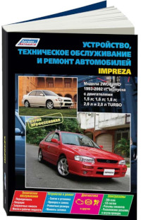
Руководство по техническому обслуживанию и ремонту автомобиля Subaru Impreza 1993-2002 годов выпуска с бензиновыми двигателями объемом 1,5/1,6/1,8/2,0 л.
- Автор: —
- Издательство: Легион-Автодата
- Год издания: —
- Страниц: 656
- Формат: —
- Размер: —
Руководство по техническому обслуживанию и ремонту автомобилей Subaru Impreza/Impreza WRX/Impreza WRX STI с 2007 года выпуска с бензиновыми двигателями объемом 1,5/2,0/2,5 л.
- Автор: —
- Издательство: Легион-Автодата
- Год издания: 2012
- Страниц: 600
- Формат: —
- Размер: —


По просьбам подписчиков выкладываю мануалы на Subaru Impreza 2008 и Subaru Forester 2008, официальный каталог аксессуаров на Subaru Impreza 2008 (которые интересуют многих!), график прохождения ТО, информационную брошюру Subaru Impreza XV и официальные рекомендации от Motul и Liqui Moly по всем жидкостям, каталог шумоизоляции STP, таблицу весов колесных дисков в формате xls (excel).
Subaru Impreza GE GH 2008 2009 Accessory
2.67 MB
Subaru Forester SH 2008 2009 2010 Service Manual
(Архив *.iso открывается с помощью любого архиватора, например WinRAR или 7Zip)
283.71 MB
из-за нарушения авторских прав (о_О) пришлось запаковать архив дважды.
Subaru Impreza GH 2008 MY Manual
99.07 MB
Subaru Impreza GE GH WRX & STI 2008 Factory Service Manual
324.04 MB
Subaru Impreza GE GH 2009 MY Service Manual
56.07 MB
Subaru Impreza GVE GVF GRE GRF WRX & STI 2012 MY Service Manual
99.8 MB
Subaru Impreza GE GH GRB WRX STI 2008 Service Repair Manual
330.67 MB
Subaru Impreza GVE GVF GRE GRF WRX & STI 2011 MY Full Service Manual
91.89 MB
Subaru Impreza GE GH GRB 2008 Руководство По Эксплуатации
7.96 MB
Subaru Impreza XV Информационная Брошюра
2.49 MB
Рекомендации компании Motul для Subaru Impreza 2.0R GE GH GR GV 2007-2012
87.43 KB
Рекомендации компании Luqiu Moly для Subaru Impreza 2.0R GE GH GR GV 2007-2012
87.43 KB
График ТО автомобилей Subaru и нормативы времени
114.62 KB
Руководство по кузовному ремонту Subaru Impreza 2008 GH GE, включая карту оцинковки, заводской антикор итд
17.39 MB
Шумоизоляция STP, каталог с артикулами
1.17 MB
Таблица вес дисков excel (Wheel Weight.xls)
505 KB
Если файл удален с обменника, пишите — перезалью!
<Данный способ связи не предназначен для предъявления требований, предусмотренных статьями 18, 19 Закона РФ от 07.02.1992 N 2300-1 «О защите прав потребителей».
При возникновении данных требований, просьба обращаться письменно по адресу: 115280, город Москва, улица Автозаводская, дом 21А, этаж 2 ООО «Субару Мотор».
Для корректной доставки письма объем вложений не должен превышать 10 Мб.

- Manuals
- Brands
- Subaru Manuals
- Automobile
- 2009 IMPREZA
- Service manual
-
Contents
Table of Contents -
Bookmarks
Quick Links
Foreword
FOREWORD
1. Foreword
A: FOREWORD
These manuals are used when performing mainte-
nance, repair or diagnosis of Subaru IMPREZA.
Applicable model:
2009MY GE*****, GH*****
The manuals contain the latest information at the
time of publication. Changes in the specifications,
methods, etc. may be made without notice.
FW-2
Related Manuals for Subaru 2009 IMPREZA
Summary of Contents for Subaru 2009 IMPREZA
-
Page 1
Foreword FOREWORD 1. Foreword A: FOREWORD These manuals are used when performing mainte- nance, repair or diagnosis of Subaru IMPREZA. Applicable model: 2009MY GE*****, GH***** The manuals contain the latest information at the time of publication. Changes in the specifications, methods, etc. -
Page 2: How To Use This Manuals
How to Use This Manuals HOW TO USE THIS MANUALS 1. How to Use This Manuals A: HOW TO USE THIS MANUALS 1. STRUCTURE Each section consists of SCT that are broken down into SC that are divided into sections for each com- ponent.
-
Page 3
How to Use This Manuals HOW TO USE THIS MANUALS 3. COMPONENT Illustrations are provided for each component. The information necessary for repair work (tightening torque, grease up points, etc.) is described on these illustrations. Information is described using symbol. To order parts, refer to parts catalogue. -
Page 4
How to Use This Manuals HOW TO USE THIS MANUALS 4. SPECIFICATION If necessary, specifications are also included. 5. INSPECTION Inspections to be carried out before and after maintenance are included. 6. MAINTENANCE • Maintenance instructions for serviceable parts describe work area and detailed step with illustration. It also describes the use of special tool, tightening torque, caution for each procedure. -
Page 5
How to Use This Manuals HOW TO USE THIS MANUALS 7. DIAGNOSIS Tables showing a step-by-step process make it easy to conduct diagnosis. 8. SI UNITS Measurements in these manuals are according to the SI units. Metric and yard/pound measurements are also included. -
Page 6
: Engine Control Module SOHC : Single Overhead Camshaft : Electronic Gasoline Injection : Supplemental Restraint System : Engine : Subaru Select Monitor : Exhaust Gas Recirculation : Special Tool : Exhaust : Switch : Electronic Throttle Control : Tumble Generator Valve : Fuse &… -
Page 7
Impreza SPECIFICATIONS 1. Impreza A: DIMENSION Model 4 door 5 door OUTBACK Overall length mm (in) 4,580 (180.3) 4,415 (173.8) Overall width mm (in) 1,740 (68.5) Overall height (at C.W.) mm (in) 1,475 (58.1) 1,480 (58.3) Length mm (in) 1,985 (78.1) Width mm (in) 1,475 (58.1) -
Page 8
Impreza SPECIFICATIONS D: TRANSMISSION Model 2.5 L Turbo 2.5 L Transmission type Clutch type DSPD DSPD 3.166 2.785 3.454 2.785 1.882 1.545 2.062 1.545 1.296 1.000 1.448 1.000 Gear ratio 0.972 0.694 1.088 0.694 0.738 — 0.780 — — — —… -
Page 9
Impreza SPECIFICATIONS I: CAPACITY 2.5 L Turbo 2.5 L Model Fuel tank 2 (US gal, Imp gal) 64 (16.9, 14.1) Capacity 2 (US qt, Imp qt) 5.0 (5.3, 4.4) (at overhaul) When replacing Engine oil engine oil and 2 (US qt, Imp qt) 4.2 (4.4, 3.7) oil filter When replacing… -
Page 10
Impreza SPECIFICATIONS J: WEIGHT 4 door SOHC Model 2.5 i OP code 1,390 1,395 1,385 1,405 1,405 1,395 1,420 1,425 1,415 1,435 Total (lb) (3,064) (3,075) (3,053) (3,097) (3,097) (3,075) (3,130) (3,141) (3,119) (3,163) Curb weight Front (C.W.) (lb) (1,719) (1,719) (1,708) (1,730) -
Page 11
Impreza SPECIFICATIONS 4 door SOHC DOHC Turbo Model 2.5 i 2.5 i-S 2.5 GT OP code 1,435 1,425 1,415 1,420 1,445 1,450 1,470 1,470 1,475 Total (lb) (3,163) (3,141) (3,119) (3,130) (3,185) (3,196) (3,240) (3,240) (3,251) Curb weight Front (C.W.) (lb) (1,796) (1,785) -
Page 12
Impreza SPECIFICATIONS 4 door DOHC Turbo Model WRX-S 2.5GT-S WRX-SS OP code 1,430 1,455 1,485 1,460 1,440 1,465 1,465 1,465 1,470 Total (lb) (3,152) (3,207) (3,273) (3,218) (3,174) (3,229) (3,229) (3,229) (3,240) Curb weight Front (C.W.) (lb) (1,807) (1,829) (1,885) (1,863) (1,818) (1,840) -
Page 13
Impreza SPECIFICATIONS 5 door SOHC Model 2.5 i OP code 1,390 1,395 1,385 1,405 1,405 1,395 1,420 1,425 1,415 1,435 Total (lb) (3,064) (3,075) (3,053) (3,097) (3,097) (3,075) (3,130) (3,141) (3,119) (3,163) Curb weight Front (C.W.) (lb) (1,719) (1,719) (1,708) (1,730) (1,730) (1,719) -
Page 14
Impreza SPECIFICATIONS 5 door SOHC DOHC Turbo Model OUTBACK 2.5 i 2.5 i-S 2.5 GT SPORT OP code 1,435 1,425 1,415 1,420 1,445 1,450 1,410 1,440 1,470 1,470 Total (lb) (3,163) (3,141) (3,119) (3,130) (3,185) (3,196) (3,108) (3,174) (3,240) (3,240) Curb weight Front (C.W.) -
Page 15
Impreza SPECIFICATIONS 5 door DOHC Turbo Model 2.5 GT WRX-S 2.5GT-S WRX-SS OP code 1,475 1,430 1,455 1,485 1,460 1,440 1,465 1,465 1,465 1,470 Total (lb) (3,251) (3,152) (3,207) (3,273) (3,218) (3,174) (3,229) (3,229) (3,229) (3,240) Curb weight Front (C.W.) (lb) (1,874) (1,807) -
Page 16
Precaution PRECAUTION 1. Precaution 6. AIRBAG To prevent bodily injury from unexpected deploy- A: CAUTION ment of airbags and unnecessary maintenance, fol- Please clearly understand and adhere to the follow- low the instructions in this manual when performing ing general precautions for environmental protec- maintenance on or near the airbag components, tion and to avoid minor or serious injury to the around front of the vehicle (radiator panel, front… -
Page 17
Precaution PRECAUTION 12.OIL When handling oil, adhere to the following to pre- vent unexpected accident. • Prepare a container and cloth to prevent scatter- ing of oil when performing work where oil can be spilled. If the oil spills, wipe it off immediately to pre- vent from penetrating into floor or flowing out for environmental protection. -
Page 18
Precaution PRECAUTION PC-4… -
Page 19
• Be sure to use the rigid racks with rubber at- Use genuine parts for maximum performance and tached to cradle to support the vehicle. maintenance when conducting repairs. Subaru/FHI • When using a plate lift, use a rubber attachment. will not be responsible for poor performance result- (Model with side sill cover) ing from the use of parts except for genuine parts. -
Page 20
Note NOTE • Do not use the plate lift whose attachment does not reach the supporting locations. The figure of vehicle indicates the supporting locations, supporting procedures, etc. for 5 door model, and they are same for 4 door model. Supporting locations NT-00239 Pantograph jack… -
Page 21
Note NOTE Lift NT-00241 Attachment Rigid rack NT-00242 Attachment NT-4… -
Page 22
Note NOTE Plate lift NT-00243 Attachment • Use the attachment by aligning its position as fol- • Model with side sill spoiler lows. For the models with side sill spoiler, align the • Model without side sill spoiler center of attachment with the center of vehicle cutout portion (the center of spoiler cutout por- For the models without side sill spoiler, align the tion). -
Page 23
Note NOTE NT-00210 Front Rear Front crossmember Rear differential NT-6… -
Page 24
Note NOTE 8. TIE-DOWNS The tie-down hooks are used when transporting vehicles and when using the chassis dynamo. Attach tie- down only to the specified locations on the vehicle. • TIE-DOWN LOCATION NT-00218 Hook for tie-down NT-7… -
Page 25
Note NOTE • TIE-DOWN HOOK & EYE BOLT NT-00213 Front tie-down hook Rear tie-down hook Eye bolt NT-8… -
Page 26
Note NOTE • TIE-DOWN DIRECTION CAUTION: Pull the tie-down chains LH and RH in the same direction, but front and rear side in the counter di- rection. Recommended Tie-down direction NT-00214 NT-00215 NT-9… -
Page 27
Note NOTE • TIE-DOWN RANGE For ground transportation CAUTION: When the vehicle is tied down from vehicle inside, hook the hooks of tie-down chain on the rear tie- down hooks from vehicle inside. When the vehicle is tied down from vehicle outside, hook the hooks of tie-down chain on the rear tie-down hooks from vehicle outside. -
Page 28
Note NOTE For sea transportation CAUTION: The eye bolts are exclusively used for towing and sea transportation tie-down, and do not use them for ground and freight transportation. :(C) NT-00236 Front tie-down hook Chain pulling range at tie-down 400 mm (15.7 in) condition Eye bolt 1,320 mm (52.0 in) -
Page 29
Note NOTE • VEHICLE SINKING VOLUME AT TIE-DOWN CONDITION CAUTION: The vehicle sinking volume at tie-down condition should be less than 50 mm (1.97 in) and make sure to fix the vehicle securely. Check to see if the tensions of chains or belts at tie-down condition are appropriate in the following procedures. -
Page 30
Note NOTE • NOTES FOR THE USE OF TIE-DOWN HOOK When the vehicle is tied down from the rear side, use the holes at the rear side, and when the vehicle is tied down from the front side, use the holes at the front side. When the vehicle is tied down from vehicle inside, hook the hooks of tie-down chain from vehicle inside, and when the vehicle is tied down from vehicle outside, hook the hooks of tie-down chain from vehicle outside. -
Page 31
Note NOTE 9. TOWING Avoid towing vehicles except when the vehicle cannot be driven. For models with AWD and AT, use a car carrier truck instead of towing. When towing other vehicles, pay attention to the following to prevent hook or vehicle damage resulting from excessive weight. -
Page 32
Note NOTE • REAR NT-00192 Eye bolt Jack handle CAUTION: When tightening the eye bolt using a wheel wrench, be careful not to scratch the bumper. NT-00224 (A) Eye bolt (B) Wheel wrench NT-15… -
Page 33
Note NOTE 10.LOADING ONTO CAR CARRIER TRUCK CAUTION: • When carrying the vehicle onto a car carrier truck, perform the operation being careful with the gap between the height of the carrier’s floor and the vehicle lower side because of little clearance under the front bumper. -
Page 34
Note NOTE 11.FRONT HOOD DAMPER STAY 1) Always perform works such as inspections and maintenance with both damper stays attached. CAUTION: • At the inspection and general maintenance, do not detach the damper stays. NT-00335 Normal attached position 2) When wider hood opening is necessary, set the damper stay below as shown in the figure. Tightening torque: <Ref. -
Page 35
For an information about training, contact a dealer or agent. 13.GENERAL SCAN TOOL Using general scan tools will greatly improve the ef- ficiency of repairing engine electronic controls. Subaru Select Monitor can be used to diagnose the engine, VDC, AT and other electronically controlled parts. NT-18… -
Page 36
Identification IDENTIFICATION 1. Identification A: IDENTIFICATION 1. IDENTIFICATION NUMBER & LABEL LOCATIONS The V.I.N. (Vehicle Identification Numbers) is used to classify the vehicle. • POSITIONING OF THE LABEL FOR IDENTIFICATION (4),(5) ID-00224 Vehicle identification number Emission control label MVSS label (Left side) (V.I.N.) Tire inflation pressure label Model number label (Right side) -
Page 37
Identification IDENTIFICATION • ENGINE • REAR DIFFERENTIAL ID-00059 DI-00502 (1) Engine serial number (1) Identification (white paint) (2) Engine type (Crankcase upper side) • MODEL NUMBER LABEL • AUTOMATIC TRANSMISSION ID-00296 ID-00262 (1) AT type and transmission serial number label •… -
Page 38
Identification IDENTIFICATION 2. MEANING OF V.I.N. The meaning of the V.I.N. is as follows: ]JF1GE636X9G500001[ The starting and ending brackets ( ] [ ) are stop marks. Digits Code Meaning Details 1 — 3 Manufacturer body area JF1: Passenger car, FHI made Car line G: IMPREZA Body type… -
Page 39
Identification IDENTIFICATION Engine EJ253BS1FB Digits Code Meaning Details 1 and 2 Engine type EJ: 4 cylinder 3 and 4 Displacement 25: 2.5 L Fuel feed system 3: MFI non-turbo (SOHC) 5: MFI turbo Exhaust regulations B: U.S. (FED, CAL) Transmission E: 5MT (WAD) P: AT S: 5MT… -
Page 40
Identification IDENTIFICATION Option code • 1-digit number Aluminum wheel — — Cruise control Leather package — — Genuine leather seat — — — — — — — — High grade audio — — — — — Navigation system — — —… -
Page 41
Recommended Materials RECOMMENDED MATERIALS 1. Recommended Materials A: RECOMMENDED MATERIALS 1. GENERAL To insure the best performance, always use the specified oil, gasoline, adhesive, sealant, etc. or a substitute of equivalent quality. 2. FUEL Always use gasoline of the same or higher octane value than specified in the owner’s manual. -
Page 42
Recommended Materials RECOMMENDED MATERIALS SAE viscosity No. and applicable temperature Engine oil –30 –20 –10 (˚C) –22 –4 (˚F) RM-00067 (1) 10W-30, 10W-40 (2) 5W-30, 5W-40 Recommended Manual transmission oil, front differential gear oil and rear differential gear oil –30 –20 –10 (˚C) -
Page 43
Cooling system conditioner SOA345001 — agent 6. REFRIGERANT Standard air conditioners on Subaru vehicles use HFC134a refrigerant. Do not mix it with other refrigerants. Also, do not use any compressor oil except for DH-PR. Air conditioner Recommended materials Item number… -
Page 44
Recommended Materials RECOMMENDED MATERIALS 7. GREASE Use grease and supplementary lubricants shown in the table below. Grease Application point Recommended materials Item number Alternative Supplementary lubricants Oxygen sensor Spray type lubricant 004301003 — MT main shaft (Spline parts) NICHIMOLY N-130 —… -
Page 45
Recommended Materials RECOMMENDED MATERIALS 9. SEAL MATERIAL Use the seal material shown in the table below, or equivalent. Seal material Application point Recommended materials Item number Alternative • Torque converter clutch case THREE BOND 1215 004403007 DOW CORNING No. 7038 •… -
Page 46
Pre-delivery Inspection PRE-DELIVERY INSPECTION 1. Pre-delivery Inspection A: GENERAL DESCRIPTION The purposes of the pre-delivery inspection (PDI) are as follows. • Remove the additional parts used for ensuring the vehicle quality during transportation and restore the ve- hicle to its normal condition. •… -
Page 47
Pre-delivery Inspection PRE-DELIVERY INSPECTION Operation Check point 14. Engine oil Check the engine oil amount. 15. Transmission gear oil Check the transmission gear oil amount. 16. AT front differential oil Check the AT front differential oil amount. 17. Engine coolant Check the engine coolant level. -
Page 48
Pre-delivery Inspection PRE-DELIVERY INSPECTION Checks after Dynamic Test Operation Check point 48. ATF level Check that the ATF level is correct. 49. Power steering fluid level Check that the power steering fluid level is normal. 50. Fluid leakage Check for fluid/oil leaks. 51. -
Page 49
Pre-delivery Inspection PRE-DELIVERY INSPECTION 5. CHILD SAFETY LOCK 3) Close all doors, and press the lock side of power door lock switch on the driver’s and passenger’s 1) Set the child safety lock lever on both rear doors sides. Check that all doors including rear gate are to the lock position. -
Page 50
Pre-delivery Inspection PRE-DELIVERY INSPECTION 7. REAR GATE LOCK/UNLOCK AND 8. OPERATION CHECK OF TRUNK LID OPEN/CLOSE OPERATIONS RELEASE HANDLE 1) Open and close the rear gate several times for 1) Use a flat tip screwdriver. Slide the screwdriver smooth movement. blade from the slit aperture of the lock assembly ful- ly to the end until you hear a click. -
Page 51
Pre-delivery Inspection PRE-DELIVERY INSPECTION 9. FUEL LID OPENER LOCK RELEASE 5 door LEVER Operate the fuel lid lock release lever to check that the fuel lid is unlocked normally. Check that the fill- er cap is securely closed. 10.ACCESSORY Check that the following accessories are provided. •… -
Page 52
Pre-delivery Inspection PRE-DELIVERY INSPECTION 11.FRONT HOOD LOCK RELEASE 12.BATTERY Operate the front hood release lever to check that Check the battery terminals to make sure that there the front hood is unlocked normally. are no rust or corrosions due to fluid leaks. Check that the battery caps are securely tightened. -
Page 53
Pre-delivery Inspection PRE-DELIVERY INSPECTION 14.ENGINE OIL 16.AT FRONT DIFFERENTIAL OIL Check the engine oil amount. If the amount of oil is Check the AT front differential oil amount. If the insufficient, check that no leaks are found. Then, amount of oil is insufficient, check for leaks. Then, add the necessary amount of the specified engine add the necessary amount of the specified AT front oil. -
Page 54
Pre-delivery Inspection PRE-DELIVERY INSPECTION 18.CLUTCH FLUID 21.KEYLESS ENTRY SYSTEM Check the clutch fluid amount. If the amount of fluid Check the keyless entry system operations as fol- is insufficient, check that no leaks are found. Then, lows: add the necessary amount of specified fluid. •… -
Page 55
Pre-delivery Inspection PRE-DELIVERY INSPECTION • Press the “Panic” button of the keyless transmit- Alarm sound operational check ter. Check that the panic mode (the horn keeps • The system uses the buzzer and sounds the sounding) is initiated. Also, check that this condi- alarm when the door is locked or unlocked. -
Page 56
Pre-delivery Inspection PRE-DELIVERY INSPECTION 22.SECURITY SYSTEM 5) Check that the system enters monitoring condi- tion 30 seconds after the condition in 4). Check that the security system operates as indicat- • Alarm system monitoring condition (all models) ed below. 1) Fully open all the door windows. 2) Remove the key from the ignition switch and close all the doors including rear gate. -
Page 57
Pre-delivery Inspection PRE-DELIVERY INSPECTION 7) The alarm system is in the non-monitoring con- 11) Check that the system is in the monitoring con- ditions if the driver’s side door is unlocked, the dition (all the doors become locked and the buzzer buzzer sounds twice, the hazard light flashes twice, sounds once, and the hazard light flashes once). -
Page 58
Pre-delivery Inspection PRE-DELIVERY INSPECTION 14) With one of all the doors open (including the 17) Check that the system enters monitoring condi- rear gate), press the “LOCK” side of the power door tion 30 seconds after the condition in 16). lock switch. -
Page 59
Pre-delivery Inspection PRE-DELIVERY INSPECTION 23.SEAT 25.TPMS (U. S. MODEL) 1) Check that each seat provides full functionality in 1) Turn the ignition switch to ON, and check that sliding and reclining. Check all available functions the TPMS warning light is in a normal operation of the rear seat such as a trunk-through center arm- condition. -
Page 60
Pre-delivery Inspection PRE-DELIVERY INSPECTION • Normal operation (Normal condition) *3 PI-00375 (1) Light OFF • System failure (Normal condition) PI-00377 (1) Illuminates after 25 blinks • System failure (IG ON) IGN ON PI-00378 • During tire pressure decrease warning, or ID has not registered IGN ON PI-00379… -
Page 61
CHECK ID. Does the ID of equipped trans- Go to step 6. Go to step 4. 1) While checking the display of the Subaru mitter match with the registered Select Monitor, transmit the transmitter ID using the transmitter registration tool. -
Page 62
Pre-delivery Inspection PRE-DELIVERY INSPECTION 26.ECM PROTECTOR 29.STARTING CONDITION For Canada model, check the ECM protector instal- Start the engine and check that the engine starts lation conditions. Make sure that the special nut smoothly. If the battery voltage is low, recharge or and the plastic cover of ECM protector are securely replace the battery. -
Page 63
Pre-delivery Inspection PRE-DELIVERY INSPECTION 38.LIGHTING 44.BRAKE TEST 1) Check the headlight operations. After removing Check the foot brake for normal operations. the key, turn the headlight switch from OFF to ON 45.PARKING BRAKE to make sure the headlight illuminates. Check the parking brake for normal operations. 2) Check the stop light operation. -
Page 64
Pre-delivery Inspection PRE-DELIVERY INSPECTION 48.ATF LEVEL 51.WATER LEAK TEST After selecting all positions (P, R, N, D), set the se- Spray the vehicle with water using a hose and lect lever in “P” range. Idle the engine for 1 or 2 min- check that no water enters the passenger compart- utes, and measure the ATF level. -
Page 65
Pre-delivery Inspection PRE-DELIVERY INSPECTION 52.APPEARANCE 2 6) Peel the identification seal attached to the rear combination light. 1) If protective coating (lap guard) is applied, re- move it. NOTE: • When removing the lap guard, using steam will make it easier to remove. •… -
Page 66
Pre-delivery Inspection PRE-DELIVERY INSPECTION PI-22… -
Page 67: General Description
General Description PERIODIC MAINTENANCE SERVICES 1. General Description A: GENERAL DESCRIPTION Be sure to perform periodic maintenance in order to maintain vehicle performance and find problems before they occur. PM-2…
-
Page 68
Schedule PERIODIC MAINTENANCE SERVICES 2. Schedule A: MAINTENANCE SCHEDULE 1 1. U.S. Maintenance interval [Number of months or km (miles), whichever occurs first] Months 7.5 15 22.5 30 37.5 45 52.5 60 67.5 82.5 97.5 105 112.5 120 × 1,000 km 4.8 12 72 81.4 96 108 120 132 144 156 168 Remarks… -
Page 69
Schedule PERIODIC MAINTENANCE SERVICES NOTE: 1. This inspection is not required to maintain emission warranty eligibility and it dose not affect the manufacturer’s obligations under EPA’s in-use compliance program. 2. When the vehicle is used in extremely dusty conditions, the air cleaner element should be replaced more often. 3. -
Page 70
Schedule PERIODIC MAINTENANCE SERVICES 2. CANADA Maintenance interval [Number of months or km (miles), whichever occurs first] Months 7.5 15 22.5 30 37.5 45 52.5 60 67.5 82.5 97.5 105 112.5 120 × 1,000 km 4.8 12 72 81.4 96 108 120 132 144 156 168 Remarks ×… -
Page 71
Schedule PERIODIC MAINTENANCE SERVICES B: MAINTENANCE SCHEDULE 2 Salt or other High Repeat Extremely Maintenance Repeat short corrosive humidity or Repeat Item rough/muddy cold weather interval distance drive used or mountain towing trailer road drive area coastal area area Engine oil 3.75 months 6,000 km 3,750 miles… -
Page 72: Engine Oil
API standard and SAE viscosity No. designated by SUBARU. • If vehicle is used in desert areas with very high temperatures or for other heavy duty applications,…
-
Page 73
Engine Oil PERIODIC MAINTENANCE SERVICES B: INSPECTION CAUTION: If the engine oil is spilt over exhaust pipe or the under cover, wipe it off with cloth to avoid emit- ting smoke or causing a fire. 1) Park the vehicle on a level surface. 2) Remove the oil level gauge and wipe it clean. -
Page 74: Spark Plug
Spark Plug PERIODIC MAINTENANCE SERVICES 5. Spark Plug 2. SOHC MODEL LH 1) Remove the battery. <Ref. to SC(H4SO)-22, A: REPLACEMENT REMOVAL, Battery.> 2) Remove the spark plug cords by pulling the boot. Spark plug: (Do not pull the cord itself.) Refer to “SPECIFICATION”…
-
Page 75
Spark Plug PERIODIC MAINTENANCE SERVICES 3. DOHC MODEL RH 4. DOHC MODEL LH 1) Disconnect the ground cable from battery. 1) Remove the battery and battery carrier. 2) Disconnect the air duct from the secondary air pump. 3) Remove the bolts attaching the air duct to the rocker cover (LH) and raise the air duct. -
Page 76
V-belt PERIODIC MAINTENANCE SERVICES 6. V-belt 2. PROCEDURE (WITH BELT TENSION GAUGE) A: INSPECTION 1) Replace the belts if cracks, fraying or wear are found. CAUTION: Check and adjust the front side belt tension so 2) Remove the V-belt covers and radiator reservoir tank. -
Page 77
V-belt PERIODIC MAINTENANCE SERVICES B: REPLACEMENT 3. REAR SIDE BELT (FOR A/C) CAUTION: 1. V-BELT COVER Always use new rear side belt. Remove the V-belt covers. 1) Remove the front side belts. 2) Cut the rear side belt. 3) Install a new belt using an installation jig. <Ref. to ME(H4SO)-40, REAR SIDE BELT, INSTALLA- TION, V-belt.>… -
Page 78: Timing Belt
Timing Belt PERIODIC MAINTENANCE SERVICES 7. Timing Belt 7) Using ST, turn the crankshaft and align the align- ment marks on crankshaft and left and right cam A: REPLACEMENT sprockets with alignment marks of belt cover and oil pump. 1. NON-TURBO MODEL ST 499987500 CRANKSHAFT SOCKET 1) Remove the radiator fan and air conditioner fan.
-
Page 79
Timing Belt PERIODIC MAINTENANCE SERVICES 11) Remove the automatic belt tension adjuster as- 6) Remove the timing belt guide. (MT model) sembly. PM-00008 PM-00011 12) Install in the reverse order of removal. <Ref. to ME(H4SO)-50, INSTALLATION, Timing Belt.> 2. TURBO MODEL 1) Remove the radiator fan and air conditioner fan. -
Page 80
Timing Belt PERIODIC MAINTENANCE SERVICES 7) Using ST, turn the crankshaft and align the align- 11) Install in the reverse order of removal. <Ref. to ment marks on crankshaft and left and right cam ME(H4DOTC)-52, INSTALLATION, Timing Belt.> sprockets with alignment marks of belt cover and CAUTION: oil pump. -
Page 81
Timing Belt PERIODIC MAINTENANCE SERVICES 3) When camshaft pulley or timing belt position is (5) Make sure single line (D) on exhaust cam offset, check for any defect and repair or replace as shaft pulley (LH side) is aligned to timing belt required. -
Page 82: Fuel Line
Fuel Line PERIODIC MAINTENANCE SERVICES 8. Fuel Line A: INSPECTION The fuel line is located mostly internally, so check pipes, areas near pipes, and engine compartment piping for rust, hose damage, loose band, etc. If faulty parts are found, repair or replace them. •…
-
Page 83: Fuel Filter
Fuel Filter PERIODIC MAINTENANCE SERVICES 9. Fuel Filter A: REPLACEMENT For fuel filter replacement procedure, refer to “FU” section. • Non-turbo model <Ref. to FU(H4SO)-70, Fuel Filter.> • Turbo model <Ref. to FU(H4DOTC)-78, Fuel Filter.> B: INSPECTION If the filter is clogged, or if the replacement interval has been reached, replace it.
-
Page 84: Air Cleaner Element
1) Disconnect the ground cable from battery. IN-02472 6) Install in the reverse order of removal. CAUTION: Be sure to use SUBARU genuine air cleaner el- IN-00203 ement depending on the engine type when re- 2) Disconnect the connector (A) from the mass air placing the air cleaner elements.
-
Page 85
IN-02255 6) Install in the reverse order of removal. CAUTION: Be sure to use SUBARU genuine air cleaner el- ement depending on the engine type when re- placing the air cleaner elements. Using other air cleaner element may affect the engine perfor- mance. -
Page 86: Cooling System
Cooling System PERIODIC MAINTENANCE SERVICES 11.Cooling System 2) Check the radiator cap valve open pressure us- ing radiator cap tester. A: INSPECTION NOTE: 1) To check the radiator for leakage, fill it with en- Rust or dirt on the cap may prevent valve from func- gine coolant, and attach the radiator cap tester (A) tioning normally.
-
Page 87
<Ref. CO(H4DOTC)-20, Radiator.>, <Ref. CO(H4DOTC)-24, Radiator Cap.> 4) Check the radiator fan operates using Subaru Select Monitor, when the coolant temperature rise to 95°C (203°F) or more. If it does not operate, check the radiator fan system. • Non-turbo model <Ref. -
Page 88: Engine Coolant
4) Loosen and remove the drain plug to drain en- and anti-rust agents, and is especially made for gine coolant into container. Subaru engines with an aluminum cylinder block. Always use SUBARU Super Coolant since other engine coolant may cause corrosion.
-
Page 89
2. PROCEDURE TO ADJUST THE SUBARU SUPER COOLANT CONCENTRATION CAUTION: Use the SUBARU Super Coolant with a 50 — 60% concentration in order to obtain maximum anti- freeze and anti-rust performance. To adjust the concentration of SUBARU Super Coolant according to temperature, find the proper SUBARU Super Coolant concentration in the table, and add dilution water to the SUBARU Super Coolant (concentrat- ed type) until it reaches the proper dilution. -
Page 90: Clutch System
Clutch System PERIODIC MAINTENANCE SERVICES 13.Clutch System 4) Check the fluid level using the scale on the out- side of the clutch reservoir tank (A). If the level is A: INSPECTION AND ADJUSTMENT below “MIN” (B), inspect the clutch master cylinder, operating cylinder and hydraulic line for fluid leaks.
-
Page 91: Transmission Gear Oil
Transmission Gear Oil PERIODIC MAINTENANCE SERVICES 14.Transmission Gear Oil 3) Fill the transmission gear oil through the oil level gauge hole up to the upper point of level gauge. A: REPLACEMENT Recommended gear oil: 1. MANUAL TRANSMISSION Refer to “RM” section. <Ref. to RM-2, LUBRI- CANTS, RECOMMENDED MATERIALS, Rec- 1) Drain the gear oil by removing drain plug.
-
Page 92: Automatic Transmission Fluid
ATF temperature to 70 — 80°C (158 fire. — 176°F) on Subaru Select Monitor. <Ref. to NOTE: 4AT(diag)-16, READ CURRENT DATA, OPERA- Before starting work, cool off the ATF well.
-
Page 93
Automatic Transmission Fluid PERIODIC MAINTENANCE SERVICES 7) Check the level and leaks of the ATF. <Ref. to PM-28, INSPECTION, Automatic Transmission Fluid.> PI-00570 (A) Level gauge (B) Inspection position when HOT [70 — 80°C (158 — 176°F)] (C) Upper level (D) Lower level (E) Inspection position when COLD [20 —… -
Page 94
Front & Rear Differential Gear Oil PERIODIC MAINTENANCE SERVICES 16.Front & Rear Differential Gear B: REPLACEMENT 1. FRONT DIFFERENTIAL (MT MODEL) For MT model, differential oil is used as manual A: INSPECTION transmission oil for lubricating the differential. Refer 1. FRONT DIFFERENTIAL (AT MODEL) to “Transmission Oil”. -
Page 95
Front & Rear Differential Gear Oil PERIODIC MAINTENANCE SERVICES 3. REAR DIFFERENTIAL 5) Fill differential gear oil through the oil level gauge hole. 1) Drain the oil by removing drain plug. 2) Remove the filler plug for quick draining oil. Recommended fluid: 3) Install the drain plug after draining oil. -
Page 96
Brake Line PERIODIC MAINTENANCE SERVICES 17.Brake Line 2. SERVICE BRAKE 1) Check the free play of brake pedal with a force of A: INSPECTION 10 N (1 kgf, 2 lbf) or less. 1. BRAKE LINE Brake pedal play: 0.5 — 2.0 mm (0.02 — 0.08 in) 1) Check for scratches, swelling, corrosion, traces of fluid leakage on the brake hoses or pipe joints. -
Page 97
Brake Line PERIODIC MAINTENANCE SERVICES 2) If the free play is out of specifications above, ad- (8) Check that the clearance (C) between stop- just the brake pedal as follows. per and brake switch thread end is within the specification. (1) Make sure the engine is off. -
Page 98
Brake Line PERIODIC MAINTENANCE SERVICES 3. BRAKE SERVO SYSTEM 1) With the engine off, depress the brake pedal several times applying the same pedal force. Make sure the travel distance should not change. 2) With the brake pedal depressed, start the en- gine. -
Page 99: Brake Fluid
Brake Fluid PERIODIC MAINTENANCE SERVICES 18.Brake Fluid 5) Install one end of a vinyl tube onto the air bleeder and insert the other end of the tube into a container A: INSPECTION to collect the brake fluid. 1) Check that the brake fluid level is between “MIN” and “MAX”.
-
Page 100: Disc Brake Pad And Disc
Disc Brake Pad and Disc PERIODIC MAINTENANCE SERVICES 19.Disc Brake Pad and Disc 3) Check the disc rotor, and correct or replace if it is damaged or worn. A: INSPECTION • Front 1. DISC BRAKE PAD AND DISC Disc rotor thickness mm (in) Standard 24 (0.94)
-
Page 101: Parking Brake
Parking Brake PERIODIC MAINTENANCE SERVICES 20.Parking Brake 3) Check the brake drum for wear, dents or other damage. A: INSPECTION If the inside surface of the brake drum is streaked, correct the surface with emery cloth (#200 or 1. REAR DRUM BRAKE more).
-
Page 102
Parking Brake PERIODIC MAINTENANCE SERVICES B: ADJUSTMENT 1. REAR DRUM BRAKE The main brake automatically adjusts itself, so no adjustments are needed. 2. PARKING BRAKE (REAR DISC BRAKE) For rear disc brake, adjust the parking brake after bleeding air. 1) Return the parking brake pedal fully. 2) Loosen the adjusting nut, and make the cable free. -
Page 103
Suspension PERIODIC MAINTENANCE SERVICES 21.Suspension 5) Damage of dust boots Visually inspect the ball joint dust boots. If it is dam- A: INSPECTION aged, remove the front arm. <Ref. to FS-19, Front Arm.> Measure the play of the ball point. <Ref. to 1. -
Page 104
Suspension PERIODIC MAINTENANCE SERVICES 3. WHEEL ARCH HEIGHT 3) When the toe-in and thrust angle are out of toler- ance value, adjust them so that they conform to tol- 1) Unload the cargoes and set the vehicle in curb erance value. weight (empty) condition. -
Page 105: Wheel Bearing
Wheel Bearing PERIODIC MAINTENANCE SERVICES 22.Wheel Bearing 2. REAR HUB UNIT 1) Jack-up the rear side of vehicle. A: INSPECTION 2) While holding the rear wheel by hand, swing it in and out to check bearing free play. 1. FRONT HUB UNIT 3) Loosen the wheel nuts, and remove the rear 1) Jack-up the front side of vehicle.
-
Page 106
Axle Boots & Joints PERIODIC MAINTENANCE SERVICES 23.Axle Boots & Joints A: INSPECTION 1. FRONT AND REAR AXLE BOOTS Inspect the front axle boots (A) and rear axle boots (B) for deformation, damage or failure. If faulty, re- place with a new part. <Ref. to DS-26, Front Drive Shaft.>… -
Page 107: Tire Rotation
Tire Rotation PERIODIC MAINTENANCE SERVICES 24.Tire Rotation • With instruction for the direction of tire rotation A: INSPECTION 1) When the tread has worn down to less than 1.6 mm (0.063 in) or the wear indicator appears across the tire tread, replace the tire. (Replace the right and left tire as a set.) WT-00115 (1) Front…
-
Page 108
Steering System (Power Steering) PERIODIC MAINTENANCE SERVICES 25.Steering System (Power 2. STEERING SHAFT JOINT Steering) When the steering wheel free play is excessive, disconnect the universal joint of steering shaft and A: INSPECTION check it for any play and yawing torque (at the point of the crossing direction). -
Page 109
Steering System (Power Steering) PERIODIC MAINTENANCE SERVICES 3. GEARBOX (4) Install the lock nut. While holding the adjust- ing screw with a wrench, tighten the lock nut us- 1) With the vehicle placed on a level surface, turn ing ST. the steering wheel 90°… -
Page 110
1) Positions (A) and (B) of the gearbox boot are fit- Recommended fluid: ted correspondingly in grooves (A) and (B) of the SUBARU ATF HP or DEXRON III gearbox and rod (C). Fluid capacity: 2) Clips are fitted outside of positions (A) and (B) of (0.7 US qt, 0.6 Imp qt) -
Page 111
A/C Filter PERIODIC MAINTENANCE SERVICES 26.A/C Filter A: REPLACEMENT 1) Remove the glove box damper. EI-01887 2) Disengage the stopper section and pull the glove box lid to remove it. EI-01831 3) Pinch the claw to unlock and remove the A/C fil- ter. -
Page 112
A/C Filter PERIODIC MAINTENANCE SERVICES PM-48… -
Page 113
General Description FUEL INJECTION (FUEL SYSTEMS) 1. General Description A: SPECIFICATION Capacity 64 2 (16.9 US gal, 14.1 Imp gal) Fuel tank Location Under rear seat Type Impeller Shutoff discharge pressure 550 — 850 kPa (5.6 — 8.7 kg/cm , 79.7 — 123.2 psi) Fuel pump 125 2 (33 US gal, 27.5 Imp gal)/h or more Discharge rate… -
Page 114: Intake Manifold
General Description FUEL INJECTION (FUEL SYSTEMS) B: COMPONENT 1. INTAKE MANIFOLD (13) (13) (10) (16) (11) (10) (11) (15) (10) (11) (10) (12) (11) (17) (18) (14) FU-04391 FU(H4SO)-3…
-
Page 115: Air Intake System
General Description FUEL INJECTION (FUEL SYSTEMS) Intake manifold Fuel injector pipe (17) Evaporation hose (A) Gasket (10) Fuel injector (18) Evaporation hose (B) Nipple (11) O-ring Guide pin (12) Purge control solenoid valve Tightening torque:N·m (kgf-m, ft-lb) Plug cord stay (13) Plug cord holder T1: 6.4 (0.7, 4.7)
-
Page 116
General Description FUEL INJECTION (FUEL SYSTEMS) 3. CRANKSHAFT POSITION, CAMSHAFT POSITION AND KNOCK SENSORS FU-00414 Crankshaft position sensor Camshaft position sensor Tightening torque:N·m (kgf-m, ft-lb) Knock sensor Camshaft position sensor support T1: 6.4 (0.7, 4.7) T2: 24 (2.4, 17.7) FU(H4SO)-5… -
Page 117: Fuel Tank
General Description FUEL INJECTION (FUEL SYSTEMS) 4. FUEL TANK (14) (11) (10) (13) (12) (15) (17) (16) (17) (18) (19) (20) (21) (21) FU-04412 FU(H4SO)-6…
-
Page 118
General Description FUEL INJECTION (FUEL SYSTEMS) Fuel tank (10) Fuel sub level sensor (19) Fuel tank protector RH Fuel tank band RH (11) Fuel sub level sensor upper plate (20) Fuel tank protector LH Fuel tank band LH (12) Fuel sub level sensor gasket (21) Self-locking nut Delivery tube… -
Page 119
General Description FUEL INJECTION (FUEL SYSTEMS) 5. FUEL LINE (32) (39) (33) (35) (25) (36) (37) (40) (38) (14) (34) (16) (31) (40) (19) (17) (18) (15) (27) (26) (23) (22) (24) (20) (28) (21) (29) (30) (12) (11) (10) (13) FU-03433 FU(H4SO)-8… -
Page 120
General Description FUEL INJECTION (FUEL SYSTEMS) Clip (17) Vent tube (31) Canister cover LH Clamp (18) Purge tube (32) Center canister cover Fuel delivery hose A (19) Drain valve (33) Canister cover RH Fuel delivery hose B (20) Drain valve bracket (34) Fuel filler hose Fuel damper… -
Page 121: Fuel Filler Pipe
General Description FUEL INJECTION (FUEL SYSTEMS) 6. FUEL FILLER PIPE (14) (14) (13) (10) (11) (12) FU-04295 Fuel filler pipe ASSY Clip (13) Evaporation pipe protector Evaporation pipe A Evaporation hose A (14) Evaporation hose C Fuel filler cap Grommet Filler ring (10) Evaporation pipe B…
-
Page 122: Fuel Pump
General Description FUEL INJECTION (FUEL SYSTEMS) 7. FUEL PUMP (10) (12) (13) (11) FU-04413 Sub tank bracket ASSY Fuel filter (10) Sub tank O-ring Clip (11) Cushion O-ring Spacer (12) Fuel level sensor Fuel pump harness Pump ASSY (13) Fuel temperature sensor Spring FU(H4SO)-11…
-
Page 123
General Description FUEL INJECTION (FUEL SYSTEMS) C: CAUTION • Wear appropriate work clothing, including a cap, protective goggles and protective shoes when per- forming any work. • Remove contamination including dirt and corro- sion before removal, installation or disassembly. • Keep the disassembled parts in order and pro- tect them from dust and dirt. -
Page 124: Special Tool
CONNECTOR RELEASE ST42099AE000 18471AA000 FUEL PIPE Used for draining fuel. ADAPTER ST18471AA000 1B022XU0 SUBARU SELECT Used for draining fuel and each inspection. MONITOR III KIT ST1B022XU0 2. GENERAL TOOL TOOL NAME REMARKS Circuit tester Used for measuring resistance and voltage.
-
Page 125: Throttle Body
Throttle Body FUEL INJECTION (FUEL SYSTEMS) 2. Throttle Body B: INSTALLATION Install in the reverse order of removal. A: REMOVAL NOTE: 1) Set the vehicle on a lift. Use a new gasket. 2) Disconnect the ground cable from battery. Tightening torque: 8 N·m (0.8 kgf-m, 5.9 ft-lb) C: INSPECTION 1.
-
Page 126
(METHOD WITH SUBARU SELECT MONITOR) 1) Turn the ignition switch to ON. (engine OFF) 2) Read the throttle opening angle signal and volt- age of throttle sensor using Subaru Select Monitor. <Ref. to EN(H4SO)(diag)-35, READ CURRENT DATA FOR ENGINE (NORMAL MODE), OPERA- TION, Subaru Select Monitor.>… -
Page 127
Intake Manifold FUEL INJECTION (FUEL SYSTEMS) 3. Intake Manifold 12) Disconnect the brake booster vacuum hose (A). A: REMOVAL 1) Set the vehicle on a lift. 2) Release the fuel pressure. <Ref. to FU(H4SO)- 52, RELEASING OF FUEL PRESSURE, PROCE- DURE, Fuel.>… -
Page 128
Intake Manifold FUEL INJECTION (FUEL SYSTEMS) 16) Disconnect the connectors from the engine 21) Disconnect the connector from camshaft posi- coolant temperature sensor. tion sensor. FU-00055 FU-02714 17) Disconnect the knock sensor connector. 22) Disconnect the front oxygen (A/F) sensor con- nector (A) and rear oxygen sensor connector (B). -
Page 129
Intake Manifold FUEL INJECTION (FUEL SYSTEMS) 25) Disconnect the connector from oil temperature 28) Remove the intake manifold from cylinder sensor. head. FU-02733 FU-03252 26) Remove the EGR pipe from intake manifold. B: INSTALLATION 1) Install the intake manifold onto cylinder heads. NOTE: Use a new gasket. -
Page 130
Intake Manifold FUEL INJECTION (FUEL SYSTEMS) 4) Connect the connector to the oil temperature Connect the connectors to camshaft position sensor. sensor. FU-02733 FU-02714 5) Connect the connector to the variable valve lift 9) Connect the connector to the power steering diagnosis oil pressure switch.
 -
Page 131
Intake Manifold FUEL INJECTION (FUEL SYSTEMS) 13) Connect the connector to engine coolant tem- 17) Connect the engine coolant hose (A) to throttle perature sensor. body. FU-00055 FU-01085 14) Connect the PCV hose (A) to intake manifold. 18) Connect the spark plug cords to spark plugs. 19) Install the generator. -
Page 132
Intake Manifold FUEL INJECTION (FUEL SYSTEMS) 3) Remove the throttle body. <Ref. to FU(H4SO)- 11) Remove the bolts which hold engine harness 14, REMOVAL, Throttle Body.> onto intake manifold. 4) Remove the EGR valve. <Ref. to FU(H4SO)-35, REMOVAL, EGR Valve.> 5) Remove the plug cord stay. -
Page 133
Intake Manifold FUEL INJECTION (FUEL SYSTEMS) 15) Disconnect the quick connector which hold the D: ASSEMBLY fuel injector pipe RH to the fuel pipe. NOTE: When assembling the nipple, apply liquid gasket. Liquid gasket: THREE BOND 1105 (Part No. 004403010) or equivalent Tightening torque: 17 N·m (1.7 kgf-m, 12.5 ft-lb) -
Page 134
Intake Manifold FUEL INJECTION (FUEL SYSTEMS) 5) Secure the fuel injector pipe to intake manifold 7) Secure the engine harness to intake manifold with bolts. with bolts. • RH side Tightening torque: Tightening torque: 19 N·m (1.9 kgf-m, 14.0 ft-lb) 19 N·m (1.9 kgf-m, 14.0 ft-lb) FU-03450 FU-02717… -
Page 135
Intake Manifold FUEL INJECTION (FUEL SYSTEMS) 12) Install the fuel pipe protector LH. E: INSPECTION Tightening torque: Make sure the fuel pipe and fuel hoses are not damaged and the connections are tightened firmly. 19 N·m (1.9 kgf-m, 14.0 ft-lb) FU-02325 13) Install the plug cord stay. -
Page 136: Engine Coolant Temperature Sensor
Engine Coolant Temperature Sensor FUEL INJECTION (FUEL SYSTEMS) 4. Engine Coolant Temperature C: INSPECTION Sensor 1) Immerse the engine coolant temperature sensor and a thermometer in water. A: REMOVAL CAUTION: 1) Disconnect the ground cable from battery. Take care not to allow water to get into the en- gine coolant temperature sensor connector.
-
Page 137: Crankshaft Position Sensor
Crankshaft Position Sensor FUEL INJECTION (FUEL SYSTEMS) 5. Crankshaft Position Sensor C: INSPECTION A: REMOVAL 1. CRANKSHAFT POSITION SENSOR (METHOD WITH CIRCUIT TESTER) 1) Disconnect the ground cable from battery. 1) Disconnect the ground cable from battery. IN-00203 IN-00203 2) Remove the bolt which secures crankshaft posi- 2) Remove the crankshaft position sensor.
-
Page 138
Crankshaft Position Sensor FUEL INJECTION (FUEL SYSTEMS) 6) Remove the nuts and bolts which hold the ECM to the bracket. FU-03417 7) Connect the probe to ECM connector. FU-04056 (A) To ECM connector Terminal No. Probe – Start the engine and let it idle. 9) Check the pattern is as same as the waveform and voltage shown below. -
Page 139: Camshaft Position Sensor
Camshaft Position Sensor FUEL INJECTION (FUEL SYSTEMS) 6. Camshaft Position Sensor 6) Remove the camshaft position sensor from the camshaft position sensor support. A: REMOVAL 1) Disconnect the ground cable from battery. FU-00179 B: INSTALLATION IN-00203 Install in the reverse order of removal. 2) Disconnect the connector from camshaft posi- Tightening torque: tion sensor.
-
Page 140
Camshaft Position Sensor FUEL INJECTION (FUEL SYSTEMS) 6) Connect the probe to ECM connector. 12 11 10 FU-04346 (A) To ECM connector Terminal No. Probe – 7) Start the engine and let it idle. Check the pattern is as same as the waveform and voltage shown below. -
Page 141: Knock Sensor
Knock Sensor FUEL INJECTION (FUEL SYSTEMS) 7. Knock Sensor B: INSTALLATION 1) Install the knock sensor to the cylinder block. A: REMOVAL NOTE: 1) Disconnect the ground cable from battery. Extraction area of knock sensor cord must be posi- tioned at a 60° angle relative to the engine rear. Tightening torque: 24 N·m (2.4 kgf-m, 17.7 ft-lb) IN-00203…
-
Page 142
Knock Sensor FUEL INJECTION (FUEL SYSTEMS) C: INSPECTION Measure the resistance between knock sensor ter- minals. EC-02428 Terminal No. Standard 1 and 2 560 28 k FU(H4SO)-31… -
Page 143: Throttle Position Sensor
Throttle Position Sensor FUEL INJECTION (FUEL SYSTEMS) 8. Throttle Position Sensor A: SPECIFICATION Throttle body is a non-disassembled part, so do not remove the throttle position sensor from throttle body. Refer to “Throttle Body” for removal and installation procedure. <Ref. to FU(H4SO)-14, REMOVAL, Throttle Body.>…
-
Page 144: Manifold Absolute Pressure Sensor
Manifold Absolute Pressure Sensor FUEL INJECTION (FUEL SYSTEMS) 9. Manifold Absolute Pressure Sensor A: REMOVAL 1) Disconnect the ground cable from battery. IN-00203 2) Disconnect the connector from the manifold ab- solute pressure sensor and remove the manifold absolute pressure sensor from throttle body. FU-03921 B: INSTALLATION Install in the reverse order of removal.
-
Page 145: Mass Air Flow And Intake Air Temperature Sensor
Mass Air Flow and Intake Air Temperature Sensor FUEL INJECTION (FUEL SYSTEMS) 10.Mass Air Flow and Intake Air 3) Connect terminal No. 3 to the battery positive terminal and terminal No. 4 to the battery ground Temperature Sensor terminal, terminal No. 5 to the circuit tester positive terminal and No.
-
Page 146: Egr Valve
EGR Valve FUEL INJECTION (FUEL SYSTEMS) 11.EGR Valve C: INSPECTION 1) Measure the resistance between EGR valve ter- A: REMOVAL minals. 1) Disconnect the ground cable from battery. 6 5 4 FU-04101 IN-00203 Terminal No. Standard 2) Disconnect the connector from EGR valve. 2 and 1 22 2 2 and 3…
-
Page 147: Fuel Injector
Fuel Injector FUEL INJECTION (FUEL SYSTEMS) 12.Fuel Injector 9) Remove the bolts which hold fuel injector pipe onto intake manifold. A: REMOVAL 1. RH SIDE 1) Release the fuel pressure. <Ref. to FU(H4SO)- 52, RELEASING OF FUEL PRESSURE, PROCE- DURE, Fuel.> 2) Disconnect the ground cable from battery.
-
Page 148
Fuel Injector FUEL INJECTION (FUEL SYSTEMS) Remove the bolts which hold fuel injector pipe B: INSTALLATION onto intake manifold. 1. RH SIDE Install in the reverse order of removal. NOTE: Use new O-rings. FU-02718 FU-03948 (A) O-ring (B) Fuel injector Tightening torque: 19 N·m (1.9 kgf-m, 14.0 ft-lb) FU-02719… -
Page 149
Fuel Injector FUEL INJECTION (FUEL SYSTEMS) 2. LH SIDE Tightening torque: 19 N·m (1.9 kgf-m, 14.0 ft-lb) Install in the reverse order of removal. NOTE: Use new O-rings. FU-02325 C: INSPECTION FU-03948 Measure the resistance between fuel injector termi- nals. (A) O-ring (B) Fuel injector Tightening torque:… -
Page 150
Variable Valve Lift Diagnosis Oil Pressure Switch FUEL INJECTION (FUEL SYSTEMS) 13.Variable Valve Lift Diagnosis B: INSTALLATION Oil Pressure Switch Install in the reverse order of removal. NOTE: A: REMOVAL Apply liquid gasket to the variable valve lift diagno- 1) Disconnect the ground cable from battery. sis oil pressure switch threads. -
Page 151
Oil Temperature Sensor FUEL INJECTION (FUEL SYSTEMS) 14.Oil Temperature Sensor B: INSTALLATION Install in the reverse order of removal. A: REMOVAL NOTE: 1) Disconnect the ground cable from battery. Apply liquid gasket to the oil temperature sensor threads. Liquid gasket: THREE BOND 1324 (Part No. -
Page 152
Front Oxygen (A/F) Sensor FUEL INJECTION (FUEL SYSTEMS) 15.Front Oxygen (A/F) Sensor Remove the front oxygen (A/F) sensor. CAUTION: A: REMOVAL When removing the front oxygen (A/F) sensor, 1) Set the vehicle on a lift. wait until exhaust pipe cools, otherwise it will 2) Disconnect the ground cable from battery. -
Page 153
Front Oxygen (A/F) Sensor FUEL INJECTION (FUEL SYSTEMS) 3) Install the under cover. 4) Lower the vehicle. 5) Connect the connector of front oxygen (A/F) sensor connector and fasten the harness with clips. EX-02350 (A) Front oxygen (A/F) sensor connector (B) Rear oxygen sensor connector (C) Clip 6) Connect the ground cable to battery. -
Page 154: Rear Oxygen Sensor
Rear Oxygen Sensor FUEL INJECTION (FUEL SYSTEMS) 16.Rear Oxygen Sensor
Remove the rear oxygen sensor. CAUTION: A: REMOVAL When removing the rear oxygen sensor, wait 1) Set the vehicle on a lift. until exhaust pipe cools, otherwise it will dam- 2) Disconnect the ground cable from battery. -
Page 155
Rear Oxygen Sensor FUEL INJECTION (FUEL SYSTEMS) 3) Install the under cover. 4) Lower the vehicle. 5) Connect the rear oxygen sensor connector and fasten the harness with clips. EX-02350 (A) Front oxygen (A/F) sensor connector (B) Rear oxygen sensor connector (C) Clip 6) Connect the ground cable to battery. -
Page 156
When the ECM of model with immobilizer has been replaced, be sure to perform the registra- tion of immobilizer system. (Refer to “PC appli- cation help for Subaru Select Monitor”.) NOTE: When replacing the ECM, be careful not to use the wrong spec. -
Page 157: Main Relay
Main Relay FUEL INJECTION (FUEL SYSTEMS) 18.Main Relay C: INSPECTION 1) Measure the resistance between main relay ter- A: REMOVAL minals. 1) Disconnect the ground cable from battery. IN-00203 2) Remove the main relay from the relay block on the back side of the glove box. FU-04076 Terminal No.
-
Page 158
Main Relay FUEL INJECTION (FUEL SYSTEMS) 2) Connect terminal No. 3 to battery positive termi- nal and terminal No. 4 to the battery ground termi- nal, and measure the resistance between the main relay terminals. FU-04077 Terminal No. Standard 1 and 2 Less than 1 FU(H4SO)-47… -
Page 159: Fuel Pump Relay
Fuel Pump Relay FUEL INJECTION (FUEL SYSTEMS) 19.Fuel Pump Relay C: INSPECTION 1) Measure the resistance between fuel pump relay A: REMOVAL terminals. 1) Disconnect the ground cable from battery. IN-00203 2) Remove the fuel pump relay from the relay block on the back side of the glove box.
-
Page 160
Fuel Pump Relay FUEL INJECTION (FUEL SYSTEMS) 2) Connect terminal No. 3 to battery positive termi- nal and terminal No. 4 to the battery ground termi- nal, and measure the resistance between the fuel pump relay terminals. FU-04077 Terminal No. Standard 1 and 2 Less than 1… -
Page 161: Electronic Throttle Control Relay
Electronic Throttle Control Relay FUEL INJECTION (FUEL SYSTEMS) 20.Electronic Throttle Control C: INSPECTION Relay 1) Measure the resistance between electronic throttle control relay terminals. A: REMOVAL 1) Disconnect the ground cable from battery. IN-00203 2) Remove the electronic throttle control relay from the relay block on the back side of the glove box.
-
Page 162
Electronic Throttle Control Relay FUEL INJECTION (FUEL SYSTEMS) 2) Connect terminal No. 3 to battery positive termi- nal and terminal No. 4 to the battery ground termi- nal, and measure the resistance between the electronic throttle control relay terminals. FU-04077 Terminal No. -
Page 163
5) Install the fuse of fuel pump to the main fuse box. CAUTION: 2. DRAINING FUEL Be careful not to spill fuel. (WITH SUBARU SELECT MONITOR) 6) Install the related parts in the reverse order after WARNING: draining the fuel. -
Page 164
Fuel FUEL INJECTION (FUEL SYSTEMS) 3) Remove the rear exhaust pipe and muffler. • 5 DOOR MODEL <Ref. to EX(H4SO)-10, REMOVAL, Rear Exhaust WARNING: Pipe.> <Ref. to EX(H4SO)-12, REMOVAL, Muf- Place “NO OPEN FLAMES” signs near the fler.> working area. 4) Remove the rear sub frame. -
Page 165
Disconnect the quick connector on the fuel deliv- 3) Drain fuel. <Ref. to FU(H4SO)-52, DRAINING ery tube (A). <Ref. to FU(H4SO)-76, REMOVAL, FUEL (WITH SUBARU SELECT MONITOR), Fuel Delivery and Evaporation Lines.> PROCEDURE, Fuel.> 4) Disconnect the ground cable from battery. -
Page 166
Fuel Tank FUEL INJECTION (FUEL SYSTEMS) 13) Remove the rear disc brake assembly and tie it 19) Remove the parking brake cable clamp from to the body side of the vehicle. the body. FU-03278 20) Disconnect canister drain hose (B) from canis- ter drain connector (A). -
Page 167
Fuel Tank FUEL INJECTION (FUEL SYSTEMS) (4) Remove the rear suspension assembly. 24) Disconnect the fuel filler hose (A) and evapora- tion hose (B). 22) Disconnect evaporation hose (B) from connec- tor (A). FU-03422 FU-03425 25) Support the fuel tank with a transmission jack, remove the bolts from the fuel tank band, and re- 23) Disconnect the quick connector of the evapora- move the fuel tank from the vehicle. -
Page 168
Fuel Tank FUEL INJECTION (FUEL SYSTEMS) B: INSTALLATION 3) Connect the quick connector of the evaporation hose to the evaporation pipe. 1) Support the fuel tank with a transmission jack, CAUTION: set the fuel tank in place, and temporarily tighten the bolts of the fuel tank band. -
Page 169
Fuel Tank FUEL INJECTION (FUEL SYSTEMS) 4) Connect evaporation hose (B) to connector (A). (3) Install the rear shock absorber to the rear suspension arm. NOTE: Use a new self-locking nut. Tightening torque: 120 N·m (12.2 kgf-m, 88.5 ft-lb) FU-03425 5) Tighten the bolts of the fuel tank band in the or- der shown in the figure. -
Page 170
Fuel Tank FUEL INJECTION (FUEL SYSTEMS) 9) Connect the connector to the rear ABS wheel 17) Install the rear brake hose bracket to the rear speed sensor. housing. Tightening torque: 33 N·m (3.4 kgf-m, 24.3 ft-lb) FU-03277 10) Install the heat shield cover. FU-04088 Tightening torque: 18 N·m (1.8 kgf-m, 13.3 ft-lb) -
Page 171
Fuel Tank FUEL INJECTION (FUEL SYSTEMS) 21) Install the service hole cover of fuel sub level sensor. FU-03274 22) Attach the service hole cover of the fuel pump, and attach the connector and clip. FU-03354 (A) Connector (B) Clip (C) Screw (D) Grommet 23) Install the rear seat cushion. -
Page 172
2) Release the fuel pressure. <Ref. to FU(H4SO)- 52, RELEASING OF FUEL PRESSURE, PROCE- DURE, Fuel.> 3) Drain fuel. <Ref. to FU(H4SO)-52, DRAINING FUEL (WITH SUBARU SELECT MONITOR), PROCEDURE, Fuel.> 4) Disconnect the ground cable from battery. FU-03426 12) Disconnect the fuel filler hose (A) and evapora- tion hose (B). -
Page 173
Fuel Filler Pipe FUEL INJECTION (FUEL SYSTEMS) B: INSTALLATION 4) Securely insert the fuel filler hose (A) and evap- oration hose (B) into the specified position, then at- 1) Open the fuel filler lid. tach the clamp or clip as shown in the figure. 2) Set the fuel saucer (A) with rubber gasket (C), Tightening torque: and insert the fuel filler pipe into hole from the inner… -
Page 174
Fuel Filler Pipe FUEL INJECTION (FUEL SYSTEMS) 5) Tighten the bolts and nuts which hold fuel filler C: DISASSEMBLY pipe bracket on the body. 1) Remove the shut valve from the fuel filler pipe. Tightening torque: <Ref. to EC(H4SO)-18, REMOVAL, Shut Valve.> 7.5 N·m (0.8 kgf-m, 5.5 ft-lb) 2) Remove the evaporation pipe from the fuel filler pipe. -
Page 175
Fuel Filler Pipe FUEL INJECTION (FUEL SYSTEMS) D: ASSEMBLY 1) Install the evaporation pipe to the fuel filler pipe. Tightening torque: 7.5 N·m (0.8 kgf-m, 5.5 ft-lb) FU-03428 2) Install the shut valve to the fuel filler pipe. <Ref. to EC(H4SO)-18, INSTALLATION, Shut Valve.> E: INSPECTION 1) Check that the fuel filler pipe does not have holes, cracks or is damaged in any other way. -
Page 176
1) Release the fuel pressure. <Ref. to FU(H4SO)- 52, RELEASING OF FUEL PRESSURE, PROCE- DURE, Fuel.> 2) Drain fuel. <Ref. to FU(H4SO)-52, DRAINING FUEL (WITH SUBARU SELECT MONITOR), PROCEDURE, Fuel.> 3) Disconnect the ground cable from battery. FU-02670 Remove the nuts which hold the fuel pump as- sembly to the fuel tank. -
Page 177
Fuel Pump FUEL INJECTION (FUEL SYSTEMS) B: INSTALLATION C: INSPECTION Install in the reverse order of removal while being 1) Disconnect the ground cable from battery. careful of the following. • Make sure the sealing portion is free from fuel or foreign matter before installation. -
Page 178: Fuel Level Sensor
Fuel Level Sensor FUEL INJECTION (FUEL SYSTEMS) 25.Fuel Level Sensor C: INSPECTION NOTE: A: REMOVAL When inspecting the fuel level sensor, perform the WARNING: work with it installed to the fuel pump. Place “NO OPEN FLAMES” signs near the 1) Measure the fuel level sensor float position. working area.
-
Page 179: Fuel Sub Level Sensor
76, REMOVAL, Fuel Delivery and Evaporation DURE, Fuel.> Lines.> 2) Drain fuel. <Ref. to FU(H4SO)-52, DRAINING FUEL (WITH SUBARU SELECT MONITOR),
Remove the rubber cap (C) from the nut. PROCEDURE, Fuel.> 3) Disconnect the ground cable from battery. FU-04350… -
Page 180
Fuel Sub Level Sensor FUEL INJECTION (FUEL SYSTEMS) B: INSTALLATION C: INSPECTION Install in the reverse order of removal while being 1) Measure the fuel sub level sensor float position. careful of the following. • Make sure the sealing portion is free from fuel or foreign matter before installation. -
Page 181
Fuel Filter FUEL INJECTION (FUEL SYSTEMS) 27.Fuel Filter 5) Disconnect the fuel piping connector from the fuel filter assembly in two locations. A: REMOVAL WARNING: Place “NO OPEN FLAMES” signs near the working area. CAUTION: • Be careful not to spill fuel. •… -
Page 182
Fuel Filter FUEL INJECTION (FUEL SYSTEMS) Lift the two tab holders connecting the pump as- B: INSTALLATION sembly to the fuel filter using a flat tip screwdriver 1) Assemble O-ring (A) and spacer (B) to the pump (with a shaft diameter of approx. 3 mm (0.12 in)), assembly and attach the pump assembly to the fuel etc., and separate the fuel filter and pump assem- filter. -
Page 183
Fuel Filter FUEL INJECTION (FUEL SYSTEMS) 3) Attach spring (A) to the metal rod of the sub tank 5) Connect the fuel piping connector to the fuel fil- bracket assembly, and assemble the fuel filter as- ter assembly. sembly. NOTE: NOTE: •… -
Page 184
Fuel Filter FUEL INJECTION (FUEL SYSTEMS) 7) Replace the cushion on the rear face of the sub tank with a new cushion. FU-03863 Connect the pump assembly connector to the sub tank bracket assembly. FU-03983 9) Install the fuel level sensor and fuel temperature sensor. -
Page 185
Fuel Damper FUEL INJECTION (FUEL SYSTEMS) 28.Fuel Damper A: REMOVAL WARNING: Place “NO OPEN FLAMES” signs near the working area. CAUTION: • Be careful not to spill fuel. • Catch the fuel from hoses using a container or cloth. 1) Release the fuel pressure. <Ref. to FU(H4SO)- 52, RELEASING OF FUEL PRESSURE, PROCE- DURE, Fuel.>… -
Page 186
Purge Damper FUEL INJECTION (FUEL SYSTEMS) 29.Purge Damper A: REMOVAL WARNING: Place “NO OPEN FLAMES” signs near the working area. 1) Remove the purge damper from the purge damper stay. FU-03365 2) Disconnect the evaporation hose from the purge damper. FU-03366 B: INSTALLATION CAUTION:… -
Page 187
Fuel Delivery and Evaporation Lines FUEL INJECTION (FUEL SYSTEMS) 30.Fuel Delivery and Evaporation Lines A: REMOVAL FU-03434 WARNING: (3) Remove the clip and disconnect the evapo- ration hose from the fuel pipe. Place “NO OPEN FLAMES” signs near the working area. CAUTION: Be careful not to spill fuel. -
Page 188
Fuel Delivery and Evaporation Lines FUEL INJECTION (FUEL SYSTEMS) 9) Disconnect the quick connector, and disconnect (4) Remove the right side rear quarter trim. (5 the fuel delivery tube and jet pump tube. door model) <Ref. to EI-58, REMOVAL, Rear Quarter Trim.>… -
Page 189
Fuel Delivery and Evaporation Lines FUEL INJECTION (FUEL SYSTEMS) 3) Install the right side trunk side trim. (4 door mod- 2) Connect the quick connector to pipe. el) <Ref. to EI-61, INSTALLATION, Trunk Room CAUTION: Trim.> • Make sure that the quick connector is secure- 4) Install the right side rear quarter trim. -
Page 190
Fuel Delivery and Evaporation Lines FUEL INJECTION (FUEL SYSTEMS) 3. CONNECTING THE FUEL DELIVERY C: INSPECTION HOSE 1) Make sure that there are no cracks on the fuel Connect the fuel delivery hose to the pipe with an pipes and fuel hoses. overlap of 20 to 25 mm (0.79 to 0.98 in). -
Page 191: Fuel System Trouble In General
Fuel System Trouble in General FUEL INJECTION (FUEL SYSTEMS) 31.Fuel System Trouble in General A: INSPECTION Trouble and possible cause Corrective action 1. Insufficient fuel supply to injector Fuel pump does not operate. Defective terminal contact Inspect contact, especially ground, and tighten it securely. Trouble in electromagnetic or electronic circuit parts Replace the faulty parts.
-
Page 192
General Description EMISSION CONTROL (AUX. EMISSION CONTROL DEVICES) 1. General Description A: CAUTION • Wear appropriate work clothing, including a cap, protective goggles and protective shoes when performing any work. • Remove contamination including dirt and corrosion before removal, installation or disassembly. •… -
Page 193
Front Catalytic Converter EMISSION CONTROL (AUX. EMISSION CONTROL DEVICES) 2. Front Catalytic Converter A: REMOVAL The front catalytic converter is integrated into the front exhaust pipe; therefore, refer to “Front Ex- haust Pipe” for the removal procedure. <Ref. to EX(H4SO)-6, REMOVAL, Front Exhaust Pipe.> B: INSTALLATION The front catalytic converter is integrated into the front exhaust pipe;… -
Page 194
Rear Catalytic Converter EMISSION CONTROL (AUX. EMISSION CONTROL DEVICES) 3. Rear Catalytic Converter A: REMOVAL The rear catalytic converter is integrated into the center exhaust pipe; therefore, refer to “Center Ex- haust Pipe” for the removal procedure. <Ref. to EX(H4SO)-9, REMOVAL, Center Exhaust Pipe.> B: INSTALLATION The rear catalytic converter is integrated into the center exhaust pipe;… -
Page 195
Canister EMISSION CONTROL (AUX. EMISSION CONTROL DEVICES) 4. Canister 9) Disconnect the purge tube (A), vent tube (B), drain tube A (C) and PCV drain tube (D). A: REMOVAL NOTE: 1) Disconnect the ground cable from battery. Disconnect the quick connector as shown in the fig- ure. -
Page 196
Canister EMISSION CONTROL (AUX. EMISSION CONTROL DEVICES) 11) Remove the canister cover LH. 13) Disconnect connector (C) from the drain valve, and remove the drain valve. EC-02387 EC-02293 12) Disconnect drain tube A (A) and drain tube B (B). 14) Disconnect purge tube (A) and vent tube (B). NOTE: NOTE: Disconnect the quick connector as shown in the fig-… -
Page 197
Canister EMISSION CONTROL (AUX. EMISSION CONTROL DEVICES) 15) Remove purge tube (A), vent tube (B), and Tightening torque: drain tube A (C). 18 N·m (1.8 kgf-m, 13.3 ft-lb) EC-02294 EC-02387 B: INSTALLATION Tightening torque: 8 N·m (0.8 kgf-m, 5.9 ft-lb) Install in the reverse order of removal while being careful of the following. -
Page 198
Canister EMISSION CONTROL (AUX. EMISSION CONTROL DEVICES) Tightening torque: 18 N·m (1.8 kgf-m, 13.3 ft-lb) EC-02363 EC-02386 C: INSPECTION Make sure that the canister, drain valve and tube are not cracked or loose. EC(H4SO)-8… -
Page 199
Purge Control Solenoid Valve EMISSION CONTROL (AUX. EMISSION CONTROL DEVICES) 5. Purge Control Solenoid Valve B: INSTALLATION Install in the reverse order of removal. A: REMOVAL Tightening torque: 1) Disconnect the ground cable from battery. 19 N·m (1.9 kgf-m, 14.0 ft-lb) IN-00203 EC-02253 2) Disconnect the connector and evaporation hos-… -
Page 200
Purge Control Solenoid Valve EMISSION CONTROL (AUX. EMISSION CONTROL DEVICES) C: INSPECTION 3) Connect the terminal No. 1 to the battery positive terminal and the terminal No. 2 to the battery neg- 1. PURGE CONTROL SOLENOID VALVE ative terminal. Check that air is discharged from (B), when supplying air to (A). -
Page 201
EGR Valve EMISSION CONTROL (AUX. EMISSION CONTROL DEVICES) 6. EGR Valve A: REMOVAL For removal procedures, refer to the “FU(H4SO)” section. <Ref. to FU(H4SO)-35, REMOVAL, EGR Valve.> B: INSTALLATION For installation procedure, refer to “FU(H4SO)” section. <Ref. to FU(H4SO)-35, INSTALLATION, EGR Valve.>… -
Page 202
Fuel Level Sensor EMISSION CONTROL (AUX. EMISSION CONTROL DEVICES) 7. Fuel Level Sensor A: REMOVAL For removal procedures, refer to the “FU(H4SO)” section. <Ref. to FU(H4SO)-67, REMOVAL, Fuel Level Sensor.> B: INSTALLATION For installation procedure, refer to “FU(H4SO)” section. <Ref. to FU(H4SO)-67, INSTALLATION, Fuel Level Sensor.>… -
Page 203
Fuel Temperature Sensor EMISSION CONTROL (AUX. EMISSION CONTROL DEVICES) 8. Fuel Temperature Sensor C: INSPECTION Measure the resistance between fuel temperature A: REMOVAL sensor terminals. The fuel temperature sensor and fuel level sensor CAUTION: are integrated into one unit; therefore, refer to “Fuel When measuring the resistance, check the cir- Level Sensor”… -
Page 204
Fuel Sub Level Sensor EMISSION CONTROL (AUX. EMISSION CONTROL DEVICES) 9. Fuel Sub Level Sensor A: REMOVAL For removal procedures, refer to the “FU(H4SO)” section. <Ref. to FU(H4SO)-68, REMOVAL, Fuel Sub Level Sensor.> B: INSTALLATION For installation procedure, refer to “FU(H4SO)” section. -
Page 205: Fuel Tank Pressure Sensor
Fuel Tank Pressure Sensor EMISSION CONTROL (AUX. EMISSION CONTROL DEVICES) 10.Fuel Tank Pressure Sensor B: INSTALLATION Install in the reverse order of removal. A: REMOVAL Tightening torque: WARNING: 7.35 N·m (0.7 kgf-m, 5.4 ft-lb) Place “NO OPEN FLAMES” signs near the working area.
-
Page 206
Pressure Control Solenoid Valve EMISSION CONTROL (AUX. EMISSION CONTROL DEVICES) 11.Pressure Control Solenoid C: INSPECTION Valve 1. PRESSURE CONTROL SOLENOID VALVE Measure the resistance between the pressure con- A: REMOVAL trol solenoid valve terminals. 1) Set the vehicle on a lift. 2) Disconnect the ground cable from battery. -
Page 207
Drain Filter EMISSION CONTROL (AUX. EMISSION CONTROL DEVICES) 12.Drain Filter A: SPECIFICATION The drain valve is a non-disassembled part, so do not remove the drain filter from drain valve. Refer to “Canister” for removal and installation procedures. <Ref. to EC(H4SO)-5, REMOVAL, Canister.> <Ref. -
Page 208
Shut Valve EMISSION CONTROL (AUX. EMISSION CONTROL DEVICES) 13.Shut Valve A: REMOVAL WARNING: Place “NO OPEN FLAMES” signs near the working area. CAUTION: Be careful not to spill fuel. 1) Remove the fuel filler pipe. <Ref. to FU(H4SO)- 61, REMOVAL, Fuel Filler Pipe.> 2) Disconnect the evaporation hose from the shut valve. -
Page 209
Drain Valve EMISSION CONTROL (AUX. EMISSION CONTROL DEVICES) 14.Drain Valve A: REMOVAL Refer to “Canister” for removal procedures. <Ref. to EC(H4SO)-5, REMOVAL, Canister.> B: INSTALLATION Refer to “Canister” for installation procedures. <Ref. to EC(H4SO)-7, INSTALLATION, Canister.> C: INSPECTION Measure the resistance between drain valve termi- nals. -
Page 210
PCV Hose Assembly EMISSION CONTROL (AUX. EMISSION CONTROL DEVICES) 15.PCV Hose Assembly C: INSPECTION 1) Measure the resistance between PCV hose as- A: REMOVAL sembly terminals. CAUTION: Do not remove unless the PCV hose, diagnos- tics connector and PCV valve are damaged. 1) Remove the air intake chamber. -
Page 211
General Description INTAKE (INDUCTION) 1. General Description A: COMPONENT (12) (18) (11) (10) (10) (15) (13) (14) (17) (16) IN-02543 IN(H4SO)-2… -
Page 212
General Description INTAKE (INDUCTION) Air intake duct (10) Clamp (18) Clamp Clip (11) Intake boot Resonator chamber (12) Air intake chamber Tightening torque:N·m (kgf-m, ft-lb) Air cleaner case (Front) (13) Stay LH (MT model) T1: 1 (0.1, 0.7) Spacer (14) Stay LH (AT model) T2: 3 (0.3, 2.2) Cushion… -
Page 213
A: REMOVAL CAUTION: 1) Disconnect the ground cable from battery. Be sure to use SUBARU genuine air cleaner el- ement depending on the engine type when re- placing the air cleaner elements. Using other air cleaner element may affect the engine perfor- mance. -
Page 214
Air Cleaner Case INTAKE (INDUCTION) 3. Air Cleaner Case 6) Remove the air cleaner case (rear) and air cleaner element. A: REMOVAL 1) Disconnect the ground cable from battery. IN-02542 7) Remove the bolt (A) and nut (B) which secure the air cleaner case (front) to the body. -
Page 215
Air Cleaner Case INTAKE (INDUCTION) B: INSTALLATION 4) Connect the connector (A) to the mass air flow and intake air temperature sensor, and fasten the 1) Install the bolt (A) and nut (B) which secure the harness to clip (B). air cleaner case (front) to the body. -
Page 216
Air Intake Chamber INTAKE (INDUCTION) 4. Air Intake Chamber A: REMOVAL 1) Loosen the clamp (A) which connects air intake chamber to throttle body. 2) Loosen the clamp (B) which connects intake boot to air intake chamber. 3) Remove the bolt (C) which secures air intake chamber to the air intake chamber stay. -
Page 217
Air Intake Duct INTAKE (INDUCTION) 5. Air Intake Duct A: REMOVAL Remove the clip which secures the air intake duct, and remove the air intake duct. IN-02262 B: INSTALLATION Install in the reverse order of removal. C: INSPECTION 1) Check for cracks or loose connections. 2) Check that no foreign matter is mixed in air in- take duct. -
Page 218
Resonator Chamber INTAKE (INDUCTION) 6. Resonator Chamber A: REMOVAL The resonator chamber and air cleaner case are in- tegrated into one unit; therefore, refer to “Air Clean- er Case” for the removal procedure. <Ref. to IN(H4SO)-5, REMOVAL, Air Cleaner Case.> B: INSTALLATION The resonator chamber and air cleaner case are in- tegrated into one unit;… -
Page 219
Resonator Chamber INTAKE (INDUCTION) IN(H4SO)-10… -
Page 220
General Description MECHANICAL 1. General Description A: SPECIFICATION Model 2.5 L Horizontally opposed, liquid cooled, 4-cylinder, Cylinder arrangement 4-stroke gasoline engine Belt driven, Valve system mechanism single overhead camshaft, 4 valve/cylinder Bore × Stroke mm (in) 99.5 × 79.0 (3.92 × 3.11) Displacement (cu in) 2,457 (149.94) -
Page 221
General Description MECHANICAL NOTE: US: Undersize OS: Oversize Belt tension Protrusion of adjuster rod mm (in) 5.2 — 6.2 (0.205 — 0.244) adjuster Valve rocker Clearance between shaft and arm mm (in) Standard 0.020 — 0.054 (0.0008 — 0.0021) Bending limit mm (in) 0.025 (0.00098) Constant… -
Page 222
General Description MECHANICAL Piston grade point mm (in) 38.2 (1.504) 99.505 — 99.515 (3.9175 — 3.9179) Standard Piston 99.495 — 99.505 (3.9171 — 3.9175) Outer diameter mm (in) 0.25 (0.0098) OS 99.745 — 99.765 (3.9270 — 3.9277) 0.50 (0.0197) OS 99.995 —… -
Page 223
General Description MECHANICAL B: COMPONENT 1. TIMING BELT (12) (10) (13) (15) (11) (16) (14) ME-03552 Timing belt cover No. 2 RH (10) Belt idler No. 2 Tightening torque:N·m (kgf-m, ft-lb) Timing belt guide (MT model) (11) Cam sprocket No. 2 T1: 5 (0.5, 3.7) Crank sprocket (12) -
Page 224
General Description MECHANICAL 2. CYLINDER HEAD AND CAMSHAFT (20) (26) (22) (25) (23) (24) (10) (30) (19) (14) (15) (16) (10) (17) (29) (18) (21) (11) (28) (27) (19) (12) (13) (31) ME-03997 ME(H4SO)-6… -
Page 225
General Description MECHANICAL Rocker cover RH (18) Rocker cover LH (31) Seal washer Intake valve rocker ASSY (19) Stud bolt Exhaust valve rocker ASSY (20) Rocker cover gasket RH Tightening torque:N·m (kgf-m, ft-lb) Camshaft cap RH (21) Rocker cover gasket LH T1: 6 (0.6, 4.4) Oil seal (22) -
Page 226: Valve Rocker Assembly
General Description MECHANICAL 3. VALVE ROCKER ASSEMBLY ME-02691 Intake valve rocker ASSY Exhaust rocker shaft Tightening torque:N·m (kgf-m, ft-lb) Valve rocker nut Exhaust valve rocker arm T1: 6 (0.6, 4.4) Valve rocker adjusting screw T2: 9.75 (1.0, 7.2) T3: 25 (2.5, 18.4) ME(H4SO)-8…
-
Page 227
General Description MECHANICAL 4. CYLINDER HEAD AND VALVE ASSEMBLY ME-03322 Exhaust valve Valve spring seat Retainer Intake valve Intake valve oil seal Retainer key Valve guide Valve spring Exhaust valve oil seal ME(H4SO)-9… -
Page 228: Cylinder Block
General Description MECHANICAL 5. CYLINDER BLOCK (31) (32) (29) (32) (28) (10) (11) (10) (27) (14) (15) (10) (28) (26) (29) (23) (12) (10) (22) (16) (24) (17) (13) (25) (30) (21) (18) (20) (19) ME-03982 ME(H4SO)-10…
-
Page 229
General Description MECHANICAL Oil pressure switch (17) Gasket (32) Oil pump seal Cylinder block RH (18) Oil pan Service hole plug (19) Drain plug Tightening torque:N·m (kgf-m, ft-lb) Gasket (20) Drain plug gasket T1: 5 (0.5, 3.7) Oil separator cover (21) Oil level gauge guide T2: 6.4 (0.7, 4.7) -
Page 230
General Description MECHANICAL 6. CRANKSHAFT AND PISTON (10) (12) (10) (13) (11) (15) (13) (14) (14) (11) (13) (8) (10) (13) (16) (12) (10) (19) (18) (17) (18) (17) ME-04074 Reinforcement (AT model) Piston pin (17) Crankshaft bearing #1, #3 Drive plate (AT model) (10) Snap ring… -
Page 231
General Description MECHANICAL 7. ENGINE MOUNTING ME-00413 Front cushion rubber Front engine mounting bracket Tightening torque:N·m (kgf-m, ft-lb) T1: 35 (3.6, 25.8) T2: 42 (4.3, 31.0) T3: 85 (8.7, 62.7) ME(H4SO)-13… -
Page 232
General Description MECHANICAL C: CAUTION • Wear appropriate work clothing, including a cap, protective goggles and protective shoes when per- forming any work. • Remove contamination including dirt and corro- sion before removal, installation or disassembly. • Keep the disassembled parts in order and pro- tect them from dust and dirt. -
Page 233
• Used for removing and installing cam sprocket. WRENCH (LH side) • CAM SPROCKET WRENCH (499207100) can also be used. ST18231AA010 1B022XU0 SUBARU SELECT Used for various inspections. MONITOR III KIT ST1B022XU0 498267800 CYLINDER HEAD • Used for replacing valve guides. -
Page 234
General Description MECHANICAL ILLUSTRATION TOOL NUMBER DESCRIPTION REMARKS 498457000 ENGINE STAND Used together with ENGINE STAND ADAPTER RH (499817100). ST-498457000 498457100 ENGINE STAND Used together with ENGINE STAND ADAPTER LH (499817100). ST-498457100 498497100 CRANKSHAFT Used for removing and installing the flywheel STOPPER and drive plate. -
Page 235
General Description MECHANICAL ILLUSTRATION TOOL NUMBER DESCRIPTION REMARKS 499017100 PISTON PIN GUIDE Used for installing piston pin, piston and con- necting rod. ST-499017100 499037100 CONNECTING ROD Used for removing and installing connecting rod BUSHING bushing. REMOVER AND INSTALLER ST-499037100 499587200 CRANKSHAFT OIL •… -
Page 236
General Description MECHANICAL ILLUSTRATION TOOL NUMBER DESCRIPTION REMARKS 499097700 PISTON PIN Used for removing piston pin. REMOVER ASSY ST-499097700 499207400 CAM SPROCKET Used for removing and installing cam sprocket. WRENCH (RH side) ST-499207400 ® 499497000 TORX PLUS Used for removing and installing camshaft cap. ST-499497000 499587100 OIL SEAL… -
Page 237
General Description MECHANICAL ILLUSTRATION TOOL NUMBER DESCRIPTION REMARKS 499597100 CRANKSHAFT OIL • Used for installing crankshaft oil seal. SEAL GUIDE • Used together with CRANKSHAFT OIL SEAL INSTALLER (499587200). ST-499597100 499718000 VALVE SPRING Used for removing and installing valve spring. REMOVER ST-499718000 499767200… -
Page 238
General Description MECHANICAL ILLUSTRATION TOOL NUMBER DESCRIPTION REMARKS 499767800 VALVE GUIDE Used for installing valve guides. (Exhaust side) ADJUSTER ST-499767800 499817100 ENGINE STAND • Stand used for engine disassembly and assembly. • Used together with ENGINE STAND ADAPTER RH (498457000) & LH (498457100). ST-499817100 499977400 CRANK PULLEY… -
Page 239
General Description MECHANICAL ILLUSTRATION TOOL NUMBER DESCRIPTION REMARKS 42099AE000 QUICK Used for removing the quick connector. CONNECTOR RELEASE ST42099AE000 18354AA000 VALVE ROCKER Used for installing the valve rocker assembly HOLDER (intake). (2-piece set) ST18354AA000 18258AA000 SPRING Used for installing the valve rocker assembly INSTALLER (intake). -
Page 240
Compression MECHANICAL 2. Compression 12) Perform at least two measurements per cylin- der, and make sure that the values are correct. A: INSPECTION Compression (fully open throttle): CAUTION: Standard After warming-up, engine becomes very hot. Be 1,020 — 1,275 kPa careful not to burn yourself during measure- (10.4 —… -
Page 241: Idle Speed
(2) Check the malfunction indicator light does not illuminate. 2) Warm up the engine. 3) Read the engine idle speed using Subaru Select Monitor. <Ref. to EN(H4SO)(diag)-35, READ CUR- RENT DATA FOR ENGINE (NORMAL MODE), OPERATION, Subaru Select Monitor.>…
-
Page 242: Ignition Timing
Ignition Timing MECHANICAL 4. Ignition Timing A: INSPECTION CAUTION: After warming-up, engine becomes very hot. Be careful not to burn yourself at measurement. 1) Before checking the ignition timing, check the following item: (1) Check the air cleaner element is free from clogging, spark plugs are in good condition, and hoses are connected properly.
-
Page 243: Intake Manifold Vacuum
Intake Manifold Vacuum MECHANICAL 5. Intake Manifold Vacuum A: INSPECTION 1) Warm up the engine. 2) Disconnect the brake booster vacuum hose from the intake manifold, and install the vacuum gauge. 3) Keep the engine at idle speed and read the vac- uum gauge indication.
-
Page 244: Engine Oil Pressure
Engine Oil Pressure MECHANICAL 6. Engine Oil Pressure 5) Start the engine, and measure the oil pressure. A: INSPECTION 1) Disconnect the ground cable from battery. ME-00196 Engine oil pressure: Standard IN-00203 98 kPa (1.0 kg/cm , 14 psi) or more at 600 rpm 2) Remove the oil pressure switch.
-
Page 245: Fuel Pressure
Fuel Pressure MECHANICAL 7. Fuel Pressure A: INSPECTION CAUTION: • Before removing the fuel pressure gauge, re- lease the fuel pressure. • Be careful not to spill fuel. • Catch the fuel from hoses using a container or cloth. NOTE: Check or replace the fuel pump and fuel delivery line if the fuel pressure is out of the standard.
-
Page 246: Valve Clearance
Valve Clearance MECHANICAL 8. Valve Clearance 9) When inspecting #2 and #4 cylinders (1) Disconnect the spark plug cords from spark A: INSPECTION plugs on LH side. <Ref. to IG(H4SO)-4, LH SIDE, REMOVAL, Spark Plug.> CAUTION: (2) Place a suitable container under the vehicle. If engine oil is spilt onto the exhaust pipe, wipe (3) Disconnect the PCV hose from the rocker it off with cloth to avoid emission of smoke or…
-
Page 247
Valve Clearance MECHANICAL 12) Measure the valve clearance in #3, #2 and #4 2) Adjust the #1 cylinder valve clearance. cylinder in the same measurement procedure as #1 (1) Loosen the valve rocker nut and screw. cylinder in this order. (2) Set a suitable thickness gauge. -
Page 248: Engine Assembly
Engine Assembly MECHANICAL 9. Engine Assembly 11) Remove the air intake chamber stay. A: REMOVAL 1) Set the vehicle on a lift. 2) Change the bolt installation position from (A) to (B), then open the front hood completely. Tightening torque: 7.5 N·m (0.8 kgf-m, 5.5 ft-lb) ME-00816 12) Disconnect the following connectors and ca-…
-
Page 249
Engine Assembly MECHANICAL (4) A/C compressor connector 15) Lift up the vehicle. 16) Remove the front and center exhaust pipes. <Ref. to EX(H4SO)-6, REMOVAL, Front Exhaust Pipe.> 17) Disconnect the ground cable on the engine side. ME-03389 (5) Power steering pump switch connector ME-03376 ME-03004 13) Disconnect the following hoses. -
Page 250
Engine Assembly MECHANICAL 19) Remove the nuts which secure the engine (2) Remove the clip and disconnect the evapo- mounting to the front crossmember. ration hose from the pipe. CAUTION: • Be careful not to spill fuel. • Catch the fuel from hoses using a container or cloth. -
Page 251
Engine Assembly MECHANICAL 25) Separation of engine and transmission (4) Slowly move the engine away from engine compartment. CAUTION: NOTE: Before removing the engine away from trans- mission, check to be sure no work has been Be careful not to damage adjacent parts or body overlooked. -
Page 252
Engine Assembly MECHANICAL 5) Remove the lifting device and wire ropes. 10) Install the torque converter clutch to drive plate. (AT model) (1) Insert the wrench into the crank pulley bolt and rotate the crank pulley to install the bolts which hold torque converter clutch to drive plate. -
Page 253
Engine Assembly MECHANICAL 12) Lift up the vehicle. 15) Connect the ground cable. 13) Install the bolts and nuts which hold lower side Tightening torque: of the transmission to engine. 7.5 N·m (0.8 kgf-m, 5.5 ft-lb) Tightening torque: 50 N·m (5.1 kgf-m, 36.9 ft-lb) •… -
Page 254
Engine Assembly MECHANICAL 20) Install the air intake chamber stay. C: INSPECTION Tightening torque: 1) Check that pipes, hoses, connectors and clamps are installed firmly. 16 N·m (1.6 kgf-m, 11.8 ft-lb) 2) Check the engine coolant is at specified level. 21) Install the A/C pressure hoses. -
Page 255: Engine Mounting
Engine Mounting MECHANICAL 10.Engine Mounting A: REMOVAL 1) Remove engine assembly. <Ref. ME(H4SO)-30, REMOVAL, Engine Assembly.> 2) Remove the engine mounting from the engine assembly. B: INSTALLATION Install in the reverse order of removal. Tightening torque: Engine mounting 35 N·m (3.6 kgf-m, 25.8 ft-lb) C: INSPECTION Make sure that no crack or other damages do not exist.
-
Page 256: Preparation For Overhaul
Preparation for Overhaul MECHANICAL 11.Preparation for Overhaul A: PROCEDURE 1) After removing the engine from body, secure it to ST in the following procedure. ST1 498457000 ENGINE STAND ADAPTER ST2 498457100 ENGINE STAND ADAPTER ST3 499817100 ENGINE STAND ME-00221 2) In this section the procedures described under each index are all connected and stated in order.
-
Page 257
V-belt MECHANICAL 12.V-belt B: INSTALLATION A: REMOVAL 1. FRONT SIDE BELT CAUTION: NOTE: • When reusing the front side belt, wipe off Perform the work with the engine installed to body dust and water with cloth. when replacing a single part. •… -
Page 258
V-belt MECHANICAL 2. REAR SIDE BELT CAUTION: • Do not re-use the rear side belt. • Be careful not to let oil, grease or coolant contact a new rear side belt. • Be careful not to rub the belt end surface with bare hands; exposed core may cause injury. •… -
Page 259
V-belt MECHANICAL 6) Place the belt guide while aligning it with the belt 9) Place the rib surface of the rear side belt into the line of the crank pulley on the front side belt side. crank pulley groove, so that the rear side belt comes in between the belt guide holder. -
Page 260
V-belt MECHANICAL 11) While checking the following, slowly turn the (3) The surface of the rear side belt is held by crank pulley approximately 90° clockwise so that the the belt stopper. belt guide comes to the position shown in the figure. CAUTION: When turning the crank pulley, always make sure that the belt guide is not off from the crank… -
Page 261
V-belt MECHANICAL 12) While checking the following, slowly turn the (3) The rib of the rear side belt is securely crank pulley approximately 90° clockwise so that placed on the groove of the crank pulley. the belt guide comes to the position shown in the figure. -
Page 262
V-belt MECHANICAL 13) Slowly turn the crank pulley clockwise, and in- 15) Remove the belt stopper from the compressor stall the rear side belt. bracket. CAUTION: CAUTION: Be careful that the total of procedures 8), 11), Always remove the belt stopper; failure to do so 12) and 13) does not exceed 330°;… -
Page 263
V-belt MECHANICAL C: INSPECTION Front side belt tension (without belt tension gauge): When installing new parts 1. FRONT SIDE BELT 7 — 9 mm (0.276 — 0.354 in) At inspection CAUTION: 9 — 11 mm (0.354 — 0.433 in) Check and adjust the front side belt tension so that it is within the specified range. -
Page 264
Crank Pulley MECHANICAL 13.Crank Pulley 3) Check that the tightening angle of the crank pul- ley bolt is 45° or more. Perform the following proce- A: REMOVAL dure when less than 45°. CAUTION: NOTE: If the tightening angle of crank pulley bolt is Perform the work with the engine installed to body less than 45°, the bolt is damaged. -
Page 265
Crank Pulley MECHANICAL 3) Check that the tightening angle of the crank pul- ley bolt is 65° or more. Perform the following proce- dure when less than 65°. CAUTION: If the tightening angle of crank pulley bolt is less than 65°, the bolt is damaged. In this case, the bolt must be replaced. -
Page 266: Timing Belt Cover
Timing Belt Cover MECHANICAL 14.Timing Belt Cover A: REMOVAL NOTE: Perform the work with the engine installed to body when replacing a single part. 1) Remove the V-belts. <Ref. to ME(H4SO)-39, REMOVAL, V-belt.> 2) Remove the crank pulley. <Ref. to ME(H4SO)- 46, REMOVAL, Crank Pulley.>…
-
Page 267
Timing Belt MECHANICAL 15.Timing Belt A: REMOVAL NOTE: Perform the work with the engine installed to body when replacing a single part. For operation proce- dures, refer to “Timing Belt” in the PM section. <Ref. to PM-14, Timing Belt.> 1. TIMING BELT 1) Remove the V-belts. -
Page 268
Timing Belt MECHANICAL 6) Remove the belt idler (A). B: INSTALLATION 7) Remove the belt idler No. 2 (B). 1. AUTOMATIC BELT TENSION ADJUSTER ASSEMBLY AND BELT IDLER 1) Prepare for installation of the automatic belt ten- sion adjuster assembly. CAUTION: •… -
Page 269
Timing Belt MECHANICAL 2) Install the automatic belt tension adjuster as- 3) Turn the camshaft sprocket No. 2 using ST1, sembly. and turn the camshaft sprocket No. 1 using ST2 so that their alignment marks (A) come to top posi- Tightening torque: tions. -
Page 270
Timing Belt MECHANICAL 7) After ensuring the marks on timing belt and cam- (3) Tighten the bolts mounting the timing belt shaft sprockets are aligned, remove the stopper pin guide. from belt tension adjuster. Tightening torque: 9.75 N·m (1.0 kgf-m, 7.2 ft-lb) ME-00245 Install the timing belt guide. -
Page 271
Timing Belt MECHANICAL 2. AUTOMATIC BELT TENSION ADJUSTER 3. BELT TENSION PULLEY 1) Visually check the oil seals for leaks, and rod 1) Check the mating surfaces of timing belt and ends for abnormal wear and scratches. If neces- contact point of adjuster rod for abnormal wear or sary, replace the automatic belt tension adjuster scratches. -
Page 272
Cam Sprocket MECHANICAL 16.Cam Sprocket B: INSTALLATION 1) Fasten the cam sprocket and install to the cam- A: REMOVAL shaft using ST. NOTE: NOTE: Perform the work with the engine installed to body Do not confuse cam sprockets (LH) and (RH) dur- when replacing a single part. -
Page 273
Cam Sprocket MECHANICAL C: INSPECTION 1) Check the cam sprocket teeth for abnormal wear and scratches. 2) Make sure there is no free play between cam sprocket and key. 3) Check the cam sprocket protrusion used for sen- sor for damage and contamination of foreign matter. ME(H4SO)-55… -
Page 274: Crank Sprocket
Crank Sprocket MECHANICAL 17.Crank Sprocket A: REMOVAL NOTE: Perform the work with the engine installed to body when replacing a single part. 1) Remove the V-belts. <Ref. to ME(H4SO)-39, REMOVAL, V-belt.> 2) Remove the crank pulley. <Ref. to ME(H4SO)- 46, REMOVAL, Crank Pulley.> 3) Remove the timing belt cover.
-
Page 275: Valve Rocker Assembly
Valve Rocker Assembly MECHANICAL 18.Valve Rocker Assembly (2) Remove the bolts (a) through (j) in alphabet- ical sequence. A: REMOVAL NOTE: NOTE: Leave two or three threads of bolts (i) and (j) en- gaged in order to retain the valve rocker assembly. Perform the work with the engine installed to body when replacing a single part.
-
Page 276
Valve Rocker Assembly MECHANICAL B: INSTALLATION (4) Use the ST to rotate the spring stopper in the direction of the arrow to fasten the adjuster 1) Install the valve rocker assembly. pin. (1) Temporarily tighten the bolts equally in al- ST 18258AA000 SPRING INSTALLER phabetical order as shown in the figure. -
Page 277
Valve Rocker Assembly MECHANICAL (2) Temporarily tighten the bolts in alphabetical or- E: INSPECTION der shown in the figure, tighten them in two stages. 1. INTAKE VALVE ROCKER ASSEMBLY Tightening torque: 1) If the roller or valve contact surface of valve First rocker arm is worn or dented excessively, replace 6.4 N·m (0.7 kgf-m, 4.7 ft-lb) -
Page 278
Camshaft MECHANICAL 19.Camshaft 11) Remove the camshaft cap. (1) Remove the bolts (a) and (b) in alphabetical A: REMOVAL sequence. NOTE: Perform the work with the engine installed to body when replacing a single part. Refer to “Valve Clear- ance” for preparation procedures. <Ref. to ME(H4SO)-28, Valve Clearance.>… -
Page 279
Camshaft MECHANICAL ® B: INSTALLATION (4) Tighten the TORX bolts (e) through (j) in al- phabetical sequence using the ST. 1) Apply a thin coat of engine oil to camshaft jour- ® ST 499497000 TORX PLUS nals, and install the camshaft. 2) Install the camshaft cap. -
Page 280
Camshaft MECHANICAL 3) Apply a coat of engine oil to camshaft oil seal pe- 9) Install the timing belt cover No. 2 LH. riphery and oil seal lips and install the oil seal (A) on Tightening torque: camshaft using ST1 and ST2. 5 N·m (0.5 kgf-m, 3.7 ft-lb) NOTE: Use a new oil seal. -
Page 281
Camshaft MECHANICAL (3) Connect the PCV hose. Cam base circle diameter A: 14) Install the high tension cord. Standard 15) Install timing belt cover. <Ref. 34.00 mm (1.3386 in) ME(H4SO)-48, INSTALLATION, Timing Belt Cov- Base circle step of adjacent intake cams (low er.>… -
Page 282: Cylinder Head
Cylinder Head MECHANICAL 20.Cylinder Head 12) While tapping the cylinder head with a plastic hammer, separate it from cylinder block. Remove A: REMOVAL the bolts (a) and (c) to remove cylinder head. NOTE: ( c ) • Perform the work with the engine installed to ( e ) body when replacing a single part.
-
Page 283
Cylinder Head MECHANICAL (8) Further tighten the bolts (a) and (b) by 40 — (2) Temporarily tighten the bolts in alphabetical 45°. order shown in the figure, tighten them in two stages. CAUTION: Make sure the total “re-tightening angle” of the Tightening torque: step (7) and (8) does not exceed 90°. -
Page 284
Cylinder Head MECHANICAL C: DISASSEMBLY 1) Place the cylinder head on the ST. ST 498267800 CYLINDER HEAD TABLE 2) Compress the valve spring and remove the valve spring retainer key using ST. Remove each valve and valve spring. ST 499718000 VALVE SPRING REMOVER NOTE: •… -
Page 285
Cylinder Head MECHANICAL 1) Install the valve spring and valve. E: INSPECTION (1) Coat the stem of each valve with engine oil 1. CYLINDER HEAD and insert the valve into valve guide. 1) Check for cracks or damage. Use liquid penetrant NOTE: tester on the important sections to check for fissures. -
Page 286
Cylinder Head MECHANICAL 2. VALVE SEAT 3. VALVE GUIDE Inspect the intake and exhaust valve seats, and 1) Check the clearance between valve guide and correct the contact surfaces with a valve seat cutter valve stem. The clearance can be checked by mea- if they are defective or when valve guides are re- suring respectively the outer diameter of valve placed. -
Page 287
Cylinder Head MECHANICAL (2) Insert the ST2 into valve guide and press it (5) Put a new valve guide, coated with sufficient down to remove the valve guide. oil, in the cylinder head, and insert the ST1 into valve guide. Press in until the valve guide upper ST1 498267800 CYLINDER HEAD TABLE end is flush with the upper surface of ST2. -
Page 288
Cylinder Head MECHANICAL (7) Ream the inside of valve guide using ST. 4. INTAKE AND EXHAUST VALVE Put the ST in valve guide, and rotate the ST 1) Inspect the flange of valve and valve stem, and slowly clockwise while pushing it lightly. Bring replace the valve with a new part if damaged, worn, the ST back while rotating it clockwise. -
Page 289
Cylinder Head MECHANICAL 5. VALVE SPRING 6. INTAKE AND EXHAUST VALVE OIL SEAL 1) Check the valve springs for damage, free length, 1) For the following, replace the oil seal with a new and tension. Replace the valve spring if it is not part. -
Page 290
Cylinder Block MECHANICAL 21.Cylinder Block 15) Remove the bolts which secure oil pump to cyl- inder block. A: REMOVAL NOTE: NOTE: When disassembling and checking the oil pump, loosen the relief valve plug before removing the oil Before conducting this procedure, drain the engine pump. -
Page 291
Cylinder Block MECHANICAL 22) Remove the water pipe assembly. ME-00300 ME-02889 Service hole plug Piston pin Seal washer Gasket Service hole cover Washer Snap ring O-ring 23) Remove the service hole plugs using a hexa- gon wrench [14 mm]. ME-00140 24) Remove the service hole cover. -
Page 292
Cylinder Block MECHANICAL 25) Rotate the crankshaft to bring #1 and #2 pis- tons to bottom dead center position, then remove the piston snap ring through service hole of #1 and #2 cylinders. ME-00141 26) Draw out the piston pin from #1 and #2 pistons using ST. -
Page 293
Cylinder Block MECHANICAL 31) Separate the cylinder block LH and RH. NOTE: When separating the cylinder block, do not allow the connecting rod to fall or damage the cylinder block. ME-02890 Cylinder block Crankshaft bearing Seal washer Rear oil seal Piston Washer Crankshaft… -
Page 294
Cylinder Block MECHANICAL B: INSTALLATION ME-03186 Crankshaft bearing Rear oil seal Seal washer Crankshaft O-ring Washer Cylinder block 1) Remove oil on the mating surface of cylinder 3) Apply liquid gasket to the mating surfaces of cyl- block before installation. Apply a coat of engine oil inder block RH, and position cylinder block LH. -
Page 295
Cylinder Block MECHANICAL 4) Apply a coat of engine oil to the washer and bolt Tighten the RH side cylinder block connecting thread. bolts (E — J) further in alphabetical order. NOTE: Tightening torque: Use a new seal washer. 18 N·m (1.8 kgf-m, 13.3 ft-lb) 5) Tighten the 10 mm cylinder block connecting bolts on the LH side (A —… -
Page 296
Cylinder Block MECHANICAL 11) Tighten the 8 mm and 6 mm cylinder block con- 15) Position the upper rail gap at (C) in the figure. necting bolts on the LH side (A — H) in alphabetical order. Tightening torque: (A) — (G): 25 N·m (2.5 kgf-m, 18.4 ft-lb) (H): 6.4 N·m (0.7 kgf-m, 4.7 ft-lb) ME-02722 16) Align the upper rail spin stopper (E) to the side… -
Page 297
Cylinder Block MECHANICAL 19) Install the snap ring. Before positioning the piston on the cylinder block, attach the snap ring in the service hole of the cylin- der block, and the piston hole on the opposite side. NOTE: Use new snap rings. ME-00306 (A) Front side ME-02442… -
Page 298
Cylinder Block MECHANICAL (3) Apply a coat of engine oil to the pistons and (4) Install the snap ring. cylinders and insert pistons in their cylinders us- NOTE: ing ST2. Use new snap rings. ST2 498747300 PISTON GUIDE ME-00159 ME-00157 (5) Apply liquid gasket to the threaded portion NOTE: of the service hole plug. -
Page 299
Cylinder Block MECHANICAL (6) Install the service hole plug and gasket. NOTE: Use a new gasket. Tightening torque: 70 N·m (7.1 kgf-m, 51.6 ft-lb) ME-00140 ME-02440 Piston Service hole plug Tightening torque:N·m (kgf-m, ft-lb) Piston pin Service hole cover T1: 6.4 (0.7, 4.7) Snap ring O-ring T2: 70 (7.1, 51.6) -
Page 300
Cylinder Block MECHANICAL (7) Set the parts so that the #3 and #4 cylinders 26) Apply liquid gasket to the mating surfaces of oil are on the upper side. Following the same pro- pan, and install the oil pan. cedures as used for #1 and #2 cylinders, install NOTE: the pistons and piston pins. -
Page 301
Cylinder Block MECHANICAL 28) Use the ST to lock the crankshaft, and install (2) Apply liquid gasket to the mating surfaces of the drive plate. (AT model) oil pump. ST 498497100 CRANKSHAFT STOPPER NOTE: Install within 5 min. after applying liquid gasket. Tightening torque: 72 N·m (7.3 kgf-m, 53.1 ft-lb) Liquid gasket:… -
Page 302
Cylinder Block MECHANICAL (5) Apply liquid gasket to the three bolts thread 37) Install the crank sprocket. <Ref. to ME(H4SO)- shown in figure. (when reusing bolts) 56, INSTALLATION, Crank Sprocket.> 38) Install the timing belt. <Ref. to ME(H4SO)-50, Liquid gasket: INSTALLATION, Timing Belt.>… -
Page 303
Cylinder Block MECHANICAL C: DISASSEMBLY ME-03562 Connecting rod cap Second ring Snap ring Connecting rod bearing Oil ring Connecting rod Top ring 1) Remove the connecting rod cap. 2) Remove the connecting rod bearing. NOTE: Keep the removed connecting rods, connecting rod caps and bearings in order so that they are kept in their original combinations/groups, and not mixed together. -
Page 304
Cylinder Block MECHANICAL D: ASSEMBLY ME-03154 Connecting rod bearing Second ring Tightening torque:N·m (kgf-m, ft-lb) Connecting rod Top ring T: 45 (4.6, 33.2) Connecting rod cap Snap ring Oil ring Side mark E: INSPECTION 1) Apply engine oil to the surface of the connecting rod bearings, and install the connecting rod bear- 1. -
Page 305
Cylinder Block MECHANICAL 2. CYLINDER AND PISTON 2) Measure inner diameter of each cylinder. Measure the inner diameter of each cylinder in both 1) The cylinder bore size is stamped on the front the thrust and piston pin directions at the heights as upper face of the cylinder block. -
Page 306
Cylinder Block MECHANICAL 3) When the piston is to be replaced due to general (2) If the cylinder inner diameter exceeds the or cylinder wear, select a suitable sized piston by limit after boring and honing, replace the cylin- measuring the piston clearance. der block. -
Page 307
Cylinder Block MECHANICAL 4) Check the snap ring installation groove (A) on 2) Using the piston, insert the piston ring and oil the piston for burr. If necessary, remove burr from ring into the cylinder so that they are perpendicular the groove so that the piston pin can lightly move. -
Page 308
Cylinder Block MECHANICAL 5. CONNECTING ROD 4) Inspect the connecting rod bearing for scar, peeling, seizure, melting, wear, etc. 1) Replace the connecting rod, if the large or small 5) Measure the oil clearance on each connecting end thrust surface is damaged. rod bearing using plastigauge. -
Page 309
Cylinder Block MECHANICAL The replacement procedure for the connecting 3) Inspect the crank journal and crank pin for wear. rod small end bushing is as follows. If they are not within the standard, replace the bear- ing with a suitable (undersize) one, and replace or (1) Remove the bushing from connecting rod with ST and press. -
Page 310
Cylinder Block MECHANICAL Unit: mm (in) Crank journal outer diameter Crank pin outer diameter #1, #3 #2, #4, #5 59.992 — 60.008 59.992 — 60.008 51.984 — 52.000 Journal O.D. (2.3619 — 2.3625) (2.3619 — 2.3625) (2.0466 — 2.0472) Standard Bearing size 1.998 —… -
Page 311
Oil Switching Solenoid Valve MECHANICAL 22.Oil Switching Solenoid Valve 9) Remove the oil switching solenoid valve holder from the cylinder head. A: REMOVAL 1. RH SIDE 1) Disconnect the ground cable from battery. ME-02726 (A) Oil switching solenoid valve (B) Variable valve lift diagnosis oil pressure switch (C) Oil temperature sensor IN-00203 (D) Oil switching solenoid valve holder… -
Page 312
Oil Switching Solenoid Valve MECHANICAL 11) Remove the oil switching solenoid valve holder Tightening torque: from the cylinder head. 6.4 N·m (0.7 kgf-m, 4.7 ft-lb) ME-02727 FU-03924 2. LH SIDE (A) Oil switching solenoid valve (B) Variable valve lift diagnosis oil pressure switch Install in the reverse order of removal. -
Page 313
Intake and Exhaust Valve MECHANICAL 23.Intake and Exhaust Valve A: SPECIFICATION Refer to “Cylinder Head” for removal and installa- tion procedures of the intake and exhaust valves. <Ref. to ME(H4SO)-64, REMOVAL, Cylinder Head.> <Ref. to ME(H4SO)-64, INSTALLATION, Cylinder Head.> ME(H4SO)-95… -
Page 314
Piston MECHANICAL 24.Piston A: SPECIFICATION Refer to “Cylinder Block” for removal and installa- tion procedures of pistons. <Ref. to ME(H4SO)-72, REMOVAL, Cylinder Block.> <Ref. to ME(H4SO)- 76, INSTALLATION, Cylinder Block.> ME(H4SO)-96… -
Page 315
Connecting Rod MECHANICAL 25.Connecting Rod A: SPECIFICATION Refer to “Cylinder Block” for removal and installa- tion procedures of connecting rod. <Ref. to ME(H4SO)-72, REMOVAL, Cylinder Block.> <Ref. ME(H4SO)-76, INSTALLATION, Cylinder Block.> ME(H4SO)-97… -
Page 316
Crankshaft MECHANICAL 26.Crankshaft A: SPECIFICATION Refer to “Cylinder Block” for removal and installa- tion procedures of the crankshaft. <Ref. to ME(H4SO)-72, REMOVAL, Cylinder Block.> <Ref. ME(H4SO)-76, INSTALLATION, Cylinder Block.> ME(H4SO)-98… -
Page 317: Engine Trouble In General
Engine Trouble in General MECHANICAL 27.Engine Trouble in General A: INSPECTION NOTE: The “RANK” shown in the chart shows the possibilities of the cause of trouble in order from “Very often” to “Rarely”. A — Very often B — Sometimes C —…
-
Page 318
Engine Trouble in General MECHANICAL Symptom Problem parts etc. Possible cause RANK 3) Initial combustion occurs. Engine control system <Ref. to EN(H4SO)(diag)-2, Basic Diagnostic Procedure.> Intake system Defective intake manifold gasket Defective throttle body gasket Fuel line Defective fuel pump and relay Clogged fuel line Lack of fuel or insufficient fuel Timing belt… -
Page 319
Engine Trouble in General MECHANICAL Symptom Problem parts etc. Possible cause RANK 2. Rough idle and engine Engine control system <Ref. to EN(H4SO)(diag)-2, Basic Diagnostic Procedure.> stall Intake system Loosened or cracked intake duct Loosened or cracked PCV hose Loosened or cracked vacuum hose Defective intake manifold gasket Defective throttle body gasket Defective PCV valve… -
Page 320
Engine Trouble in General MECHANICAL Symptom Problem parts etc. Possible cause RANK 3. Low output, hesitation and Engine control system <Ref. to EN(H4SO)(diag)-2, Basic Diagnostic Procedure.> poor acceleration Intake system Loosened or cracked intake duct Loosened or cracked PCV hose Loosened or cracked vacuum hose Defective intake manifold gasket Defective throttle body gasket… -
Page 321
Engine Trouble in General MECHANICAL Symptom Problem parts etc. Possible cause RANK 4. Surging Engine control system <Ref. to EN(H4SO)(diag)-2, Basic Diagnostic Procedure.> Intake system Loosened or cracked intake duct Loosened or cracked PCV hose Loosened or cracked vacuum hose Defective intake manifold gasket Defective throttle body gasket Defective PCV valve… -
Page 322
Engine Trouble in General MECHANICAL Symptom Problem parts etc. Possible cause RANK 8. Knocking Engine control system <Ref. to EN(H4SO)(diag)-2, Basic Diagnostic Procedure.> Intake system Loosened oil filler cap Timing belt Defective timing Compression Incorrect valve clearance Incorrect valve timing Cooling system Over-heating 9. -
Page 323: Engine Noise
Engine Noise MECHANICAL 28.Engine Noise A: INSPECTION Type of sound Condition Possible cause • Valve mechanism is defective. • Incorrect valve clearance Sound increases as engine Regular clicking sound • Worn valve rocker speed increases. • Worn camshaft • Broken valve spring •…
-
Page 324
Engine Noise MECHANICAL ME(H4SO)-106… -
Page 325
General Description EXHAUST 1. General Description A: COMPONENT • 4 DOOR MODEL (29) (29) (11) (18) (28) (16) (24) (10) (23) (22) (12) (13) (20) (14) (17) (15) (19) (20) (25) (30) (21) (31) (26) (27) EX-02481 EX(H4SO)-2… -
Page 326
General Description EXHAUST Gasket (16) Front oxygen (A/F) sensor (31) Hanger bracket (AT model) Spring (17) Front catalytic converter Chamber (18) Rear oxygen sensor Tightening torque:N·m (kgf-m, ft-lb) Rear exhaust pipe (19) Gasket T1: 7.5 (0.8, 5.5) Cushion rubber (20) Gasket T2: 13 (1.3, 9.6) Self-locking nut… -
Page 327
General Description EXHAUST • 5 DOOR MODEL (11) (18) (28) (16) (24) (10) (23) (22) (12) (13) (20) (14) (15) (17) (19) (20) (25) (29) (21) (30) (26) (27) EX-02482 EX(H4SO)-4… -
Page 328
General Description EXHAUST Gasket (15) Center exhaust pipe front lower (30) Hanger bracket (AT model) cover Spring Chamber (16) Front oxygen (A/F) sensor Tightening torque:N·m (kgf-m, ft-lb) Rear exhaust pipe (17) Front catalytic converter T1: 7.5 (0.8, 5.5) Cushion rubber (18) Rear oxygen sensor T2: 13 (1.3, 9.6) -
Page 329
Front Exhaust Pipe EXHAUST 2. Front Exhaust Pipe Remove the nuts which hold front exhaust pipe onto cylinder heads. A: REMOVAL CAUTION: CAUTION: Be careful not to drop the front and center ex- haust pipe assembly. Vehicle components are extremely hot after driving. -
Page 330
Front Exhaust Pipe EXHAUST B: INSTALLATION 5) Install the center exhaust pipe to rear exhaust pipe. 1) Install the front oxygen (A/F) sensor and rear ox- NOTE: ygen sensor to the front exhaust pipe. <Ref. to FU(H4SO)-41, INSTALLATION, Front Oxygen (A/ Use a new gasket. -
Page 331
Front Exhaust Pipe EXHAUST Install the under cover. 9) Lower the vehicle. 10) Connect the front oxygen (A/F) sensor connec- tor (A) and rear oxygen sensor connector (B), and fasten the harness with the clip (C). EX-02350 11) Install the air intake duct. <Ref. to IN(H4SO)-8, INSTALLATION, Air Intake Duct.>… -
Page 332
Center Exhaust Pipe EXHAUST 3. Center Exhaust Pipe A: REMOVAL 1) After removing the center and front exhaust pipes as one unit, separate them. Refer to “Front Exhaust Pipe” for the removal procedure. <Ref. to EX(H4SO)-6, REMOVAL, Front Exhaust Pipe.> 2) Remove the front oxygen (A/F) sensor and rear oxygen sensor. -
Page 333
Rear Exhaust Pipe EXHAUST 4. Rear Exhaust Pipe 6) Remove the rear exhaust pipe from the cushion rubber. A: REMOVAL CAUTION: Vehicle components are extremely hot after driving. Be wary of receiving burns from heated parts. 1) Set the vehicle on a lift. 2) Lift up the vehicle. -
Page 334
Rear Exhaust Pipe EXHAUST 3) Install the rear exhaust pipe to the muffler. NOTE: Use a new gasket and self-locking nut. Tightening torque: 48 N·m (4.9 kgf-m, 35.4 ft-lb) • 4 DOOR MODEL EX-02261 • 5 DOOR MODEL EX-02232 4) Install the rear exhaust pipe to center exhaust pipe. -
Page 335
Muffler EXHAUST 5. Muffler • 5 DOOR MODEL A: REMOVAL CAUTION: Vehicle components are extremely hot after driving. Be wary of receiving burns from heated parts. 1) Set the vehicle on a lift. 2) Lift up the vehicle. 3) Remove the muffler from rear exhaust pipe. •… -
Page 336
Fins Corrugated fin type Reservoir Capacity 2 (US qt, Imp qt) 0.45 (0.48, 0.40) tank Recommended materials Item number Alternative SUBARU SUPER COOLANT — (Concentrated type) Coolant — SUBARU SUPER COOLANT K0670Y0000 (Diluted type) Water for dilution Distilled water —… -
Page 337
General Description COOLING B: COMPONENT 1. WATER PUMP CO-02543 Water pump ASSY Gasket Tightening torque:N·m (kgf-m, ft-lb) Gasket Thermostat cover T1: First 12 (1.2, 8.9) Heater by-pass hose Clip Second 12 (1.2, 8.9) Thermostat T2: 12 (1.2, 8.9) CO(H4SO)-3… -
Page 338
General Description COOLING 2. RADIATOR & RADIATOR FAN (10) (11) (12) (24) (13) (25) (14) (16) (15) (20) (22) (17) (14) (21) (14) (14) (23) (18) (19) CO-02381 Radiator lower cushion (12) Radiator main fan shroud (22) O-ring Radiator (13) Radiator main fan, main fan motor (23) Radiator lower bracket… -
Page 339
General Description COOLING C: CAUTION • Wear appropriate work clothing, including a cap, protective goggles and protective shoes when per- forming any work. • Remove contamination including dirt and corro- sion before removal, installation or disassembly. • Keep the disassembled parts in order and pro- tect them from dust and dirt. -
Page 340
CAM SPROCKET • Used for removing and installing cam sprocket. WRENCH • CAM SPROCKET WRENCH (499207100) can also be used. ST18231AA010 1B022XU0 SUBARU SELECT Used for troubleshooting the electrical system. MONITOR III KIT ST1B022XU0 2. GENERAL TOOL TOOL NAME REMARKS Circuit tester Used for measuring resistance and voltage. -
Page 341
Radiator Fan System COOLING 2. Radiator Fan System A: WIRING DIAGRAM BATTERY MAIN SBF SBF-6 No. 3 IGNITION SWITCH No. 2 No. 26 No. 22 MAIN FUSE MAIN BOX (M/B) RELAY 1 B143 THROUGH JOINT CONNECTOR F109 B360 MAIN RELAY HOLDER RELAY 2 RELAY MAIN FAN… -
Page 342
1) Connect the delivery (test) mode connector. radiator sub fans rotate at low 2) Turn the ignition switch to ON. speed? 3) Using the Subaru Select Monitor, check the forced operation of the radiator fan relay. NOTE: • When performing a forced operation radiator… -
Page 343
2) Turn the ignition switch to ON. speed? 3) Using the Subaru Select Monitor, check the forced operation of the radiator fan relay. NOTE: • When performing a forced operation radiator… -
Page 344
Radiator Fan System COOLING Step Check CHECK HARNESS BETWEEN SUB FAN RE- Is the resistance less than 1 ? Go to step 10. Repair the open LAY TERMINAL AND SUB FAN MOTOR AS- circuit of harness SEMBLY CONNECTOR. between the sub 1) Disconnect the connector from the sub fan fan relay terminal motor assembly. -
Page 345
Radiator Fan System COOLING Step Check CHECK MAIN FAN MOTOR ASSEMBLY. Does the radiator main fan Go to step 18. Replace the main Connect the battery positive (+) terminal to ter- rotate? fan motor assem- minal No. 2 of the main fan motor assembly, and bly. -
Page 346
Radiator Fan System COOLING Step Check CHECK POOR CONTACT. Is there poor contact of ECM Repair the poor Repair the power Check for poor contact of ECM connector. connector? contact of ECM supply circuit to the connector. main fuse box. CHECK OPERATION OF RADIATOR FAN. -
Page 347
<Ref. to CO(H4SO)-14, ADJUSTMENT, Engine Coolant.> NOTE: The SUBARU Super Coolant contains anti-freeze and anti-rust agents, and is especially made for Subaru engines with an aluminum cylinder block. Always use SUBARU Super Coolant, since other coolant may cause corrosion. CO(H4SO)-13… -
Page 348
1. PROCEDURE TO ADJUST THE SUBARU SUPER COOLANT CONCENTRATION CAUTION: Use the SUBARU Super Coolant with a 50 — 60% concentration in order to obtain maximum anti- freeze and anti-rust performance. To adjust the concentration of SUBARU Super Coolant according to temperature, find the proper SUBARU Super Coolant concentration in the table, and add dilution water to the SUBARU Super Coolant (concentrat- ed type) until it reaches the proper dilution. -
Page 349: Water Pump
Water Pump COOLING 4. Water Pump 12) Remove the water pump. A: REMOVAL 1) Remove the radiator. <Ref. to CO(H4SO)-19, REMOVAL, Radiator.> 2) Remove the V-belts. <Ref. to ME(H4SO)-39, REMOVAL, V-belt.> 3) Remove the crank pulley. <Ref. to ME(H4SO)- 46, REMOVAL, Crank Pulley.> 4) Remove the timing belt cover.
-
Page 350
Water Pump COOLING 4) Install the belt cover No. 2 LH. C: INSPECTION Tightening torque: 1) Check the water pump bearing for smooth rota- tion. 5 N·m (0.5 kgf-m, 3.7 ft-lb) 2) Check the water pump pulley for abnormalities. 3) Make sure the impeller is not deformed or dam- aged. -
Page 351
Thermostat COOLING 5. Thermostat B: INSTALLATION 1) Install a gasket to thermostat. A: REMOVAL NOTE: 1) Set the vehicle on a lift. Use a new gasket. 2) Lift up the vehicle. 2) Install the thermostat and thermostat cover. 3) Remove the under cover. NOTE: 4) Drain the engine coolant. -
Page 352
Thermostat COOLING C: INSPECTION Replace the thermostat if the valve does not close completely at an ambient temperature or if the fol- lowing test shows unsatisfactory results. • Inspection method Immerse the thermostat and a thermometer in wa- ter. Raise water temperature gradually, and mea- sure the temperature and valve lift when the valve begins to open and when the valve is fully opened. -
Page 353
Radiator COOLING 6. Radiator 7) Disconnect the main fan motor assembly con- nector (A) and sub fan motor assembly connector A: REMOVAL (B). CAUTION: The radiator is pressurized when the engine and radiator are hot. Wait until engine and radi- ator cool down before working on the radiator. -
Page 354
Radiator COOLING 10) Lower the vehicle. 3) Install the radiator upper brackets and tighten the bolts. 11) Disconnect the over flow hose. 12) Remove reservoir tank. <Ref. Tightening torque: CO(H4SO)-27, REMOVAL, Reservoir Tank.> 12 N·m (1.2 kgf-m, 8.9 ft-lb) 13) Remove the air intake duct. <Ref. to IN(H4SO)- 8, REMOVAL, Air Intake Duct.>… -
Page 355
Radiator COOLING 10) Connect the radiator outlet hose. 15) Connect the ground cable to battery. CO-00270 IN-00203 11) Connect the main fan motor assembly connec- 16) Fill engine coolant. <Ref. to CO(H4SO)-13, tor (A) and sub fan motor assembly connector (B). FILLING OF ENGINE COOLANT, REPLACE- MENT, Engine Coolant.>… -
Page 356: Radiator Cap
Radiator Cap COOLING 7. Radiator Cap A: INSPECTION 1) Attach the radiator cap tester to radiator cap. CO-00044 2) Increase pressure until the radiator cap tester gauge pointer stops. Radiator cap is functioning properly if it holds the service limit pressure for 5 — 6 seconds.
-
Page 357
Radiator Main Fan and Fan Motor COOLING 8. Radiator Main Fan and Fan 10) Disconnect the radiator inlet hose from engine side. Motor A: REMOVAL 1) Set the vehicle on a lift. 2) Disconnect the ground cable from battery. CO-02485 11) Disconnect the over flow hose. -
Page 358
Radiator Main Fan and Fan Motor COOLING B: INSTALLATION D: ASSEMBLY Install in the reverse order of removal. Assemble in the reverse order of disassembly. CAUTION: Tightening torque: Check if the radiator hose and the over flow 5 N·m (0.5 kgf-m, 3.7 ft-lb) hose are properly connected. -
Page 359
Radiator Sub Fan and Fan Motor COOLING 9. Radiator Sub Fan and Fan 7) Remove the ATF hose from the clip of the radia- tor sub fan shroud. (AT model) Motor Lower the vehicle. 9) Remove the air intake duct. <Ref. to IN(H4SO)- A: REMOVAL 8, REMOVAL, Air Intake Duct.>… -
Page 360
Radiator Sub Fan and Fan Motor COOLING B: INSTALLATION D: ASSEMBLY Assemble in the reverse order of disassembly. CAUTION: Confirm that the radiator hose is securely con- Tightening torque: nected. 5 N·m (0.5 kgf-m, 3.7 ft-lb) Install in the reverse order of removal. Tightening torque: 7.5 N·m (0.8 kgf-m, 5.5 ft-lb) CO-00098… -
Page 361: Reservoir Tank
Reservoir Tank COOLING 10.Reservoir Tank A: REMOVAL 1) Disconnect the over flow hose connected to the radiator filler neck. 2) Push in the hook (A), and pull the reserve tank in the direction of the arrow to remove. CO-00279 B: INSTALLATION Install in the reverse order of removal.
-
Page 362: Engine Cooling System Trouble In General
Engine Cooling System Trouble in General COOLING 11.Engine Cooling System Trouble in General A: INSPECTION Trouble Possible cause Corrective action Replenish engine coolant, inspect for leakage, and a. Insufficient engine coolant repair it if necessary. b. Loose timing belt Repair or replace timing belt tensioner. c.
-
Page 363
General Description LUBRICATION 1. General Description A: SPECIFICATION Lubrication method Forced lubrication Pump type Trochoid type Inner rotor Number of teeth Outer rotor Outer rotor diameter × thickness mm (in) 76 × 10 (2.99 × 0.39) Tip clearance between inner and outer Specification mm (in) 0.04 —… -
Page 364
It is acceptable to fill an engine with oil of an- other brand when replacing the oil, but make sure to use an oil with an API standard and SAE viscosity number specified by Subaru. NOTE: • The proper viscosity oil helps the engine main-… -
Page 365
General Description LUBRICATION B: COMPONENT • Non-turbo model (13) (16) (15) (14) (12) (17) (28) (11) (18) (29) (32) (19) (30) (31) (20) (24) (10) (27) (22) (21) (23) (26) (25) LU-02471 Plug (15) Gasket (29) Rocker cover Gasket (16) Oil filler cap (30) O-ring… -
Page 366
General Description LUBRICATION • Turbo model (13) (26) (14) (29) (15) (12) (27) (11) (16) (17) (32) (23) (18) (31) (19) (20) (10) (30) (21) (22) (28) (24) (25) LU-02499 Plug (15) O-ring (29) Gasket Gasket (16) Rocker cover (30) O-ring Relief valve spring (17) -
Page 367
General Description LUBRICATION C: CAUTION • Wear appropriate work clothing, including a cap, protective goggles and protective shoes when performing any work. • Remove contamination including dirt and corrosion before removal, installation or disassembly. • Keep the disassembled parts in order and protect them from dust and dirt. •… -
Page 368
Oil Pressure System LUBRICATION 2. Oil Pressure System A: WIRING DIAGRAM IGNITION BATTERY SWITCH No.5 SBF-6 MAIN SBF COMBINATION METER : NON-TURBO MODEL : 31 : 45 TURBO MODEL OIL PRESSURE SWITCH 1 2 3 4 5 6 7 8 9 10 11 12 13 14 15 16 17 18 19 20 1 2 3 4 5 6 7 8 9 10 11 4 5 6 21 22 23 24 25 26 27 28 29 30 31 32 33 34 35 36 37 38 39 40… -
Page 369
Oil Pressure System LUBRICATION B: INSPECTION Step Check CHECK COMBINATION METER. Does the warning light illumi- Go to step 2. Repair or replace 1) Turn the ignition switch to ON (engine OFF). nate? the combination 2) Check other warning lights. meter. -
Page 370
Engine Oil LUBRICATION 3. Engine Oil B: REPLACEMENT CAUTION: A: INSPECTION If the engine oil is spilt over exhaust pipe or the CAUTION: under cover, wipe it off with cloth to avoid emit- If the engine oil is spilt over exhaust pipe or the ting smoke or causing a fire. -
Page 371
Engine Oil LUBRICATION 5) Tighten the engine oil drain plug after draining 10) After stopping the engine, recheck the oil level. engine oil. If necessary, add engine oil up to the “F” line on oil level gauge. NOTE: Use a new drain plug gasket. Tightening torque: 44 N·m (4.5 kgf-m, 32.5 ft-lb) •… -
Page 372: Oil Pump
Oil Pump LUBRICATION 4. Oil Pump
Remove the oil pump by using flat tip screwdriver. CAUTION: A: REMOVAL Be careful not to scratch mating surfaces of 1) Set the vehicle on a lift. cylinder block and oil pump. 2) Disconnect the ground cable from battery. LU-00016 IN-00203 9) Remove the front oil seal from the oil pump. -
Page 373
Oil Pump LUBRICATION 3) Apply a coat of engine oil to the inside of front oil 10) Connect the ground cable to battery. seal. IN-00203 ME-00312 C: DISASSEMBLY 4) Install the oil pump to cylinder block. Be careful Remove the screw which secures oil pump cover not to damage the front oil seal during installation. -
Page 374
Oil Pump LUBRICATION D: ASSEMBLY 5) Install the oil pump cover. 1) Using the ST, install the front oil seal. Tightening torque: ST 499587100 OIL SEAL INSTALLER T1: 5.4 N·m (0.6 kgf-m, 4.0 ft-lb) T2: 44 N·m (4.5 kgf-m, 32.5 ft-lb) NOTE: Use a new front oil seal. -
Page 375
Oil Pump LUBRICATION E: INSPECTION 3. SIDE CLEARANCE Measure the gap between the inner rotor and the 1. TIP CLEARANCE oil pump case to measure the clearance between Measure the tip clearance of rotors. If the clearance the oil pump inner rotor and the oil pump cover as is out of specification, replace the rotors as a set. -
Page 376
Oil Pan and Strainer LUBRICATION 5. Oil Pan and Strainer 9) Remove the radiator upper brackets. A: REMOVAL 1) Set the vehicle on a lift. 2) Disconnect the ground cable from battery. LU-02365 10) Support the engine with a lifting device and wire ropes. -
Page 377
Oil Pan and Strainer LUBRICATION 18) Remove the oil strainer. 2) Install the baffle plate. 19) Remove the baffle plate. Tightening torque: 6.4 N·m (0.7 kgf-m, 4.7 ft-lb) 3) Install the oil strainer to cylinder block. NOTE: Use new O-rings. Tightening torque: 10 N·m (1.0 kgf-m, 7.4 ft-lb) 4) Tighten the oil strainer stay together with the baf-… -
Page 378
Oil Pan and Strainer LUBRICATION 6) Tighten the bolts which install oil pan to cylinder Tighten the nuts which install engine mounting block. onto front crossmember. NOTE: Tightening torque: Make sure that the engine mounting nuts (A) and T1: 5 N·m (0.5 kgf-m, 3.7 ft-lb) locator (B) are securely installed. -
Page 379
Oil Pan and Strainer LUBRICATION 12) Remove the lifting device and wire ropes. 17) Install the air intake chamber. (Non-turbo mod- el) <Ref. to IN(H4SO)-7, INSTALLATION, Air In- take Chamber.> 18) Install the air intake duct. <Ref. to IN(H4SO)-8, INSTALLATION, Air Intake Duct.> <Ref. to IN(H4DOTC)-11, INSTALLATION, Intake… -
Page 380
Oil Pressure Switch LUBRICATION 6. Oil Pressure Switch B: INSTALLATION 1) Apply liquid gasket to the oil pressure switch A: REMOVAL threads. 1) Disconnect the ground cable from battery. Liquid gasket: THREE BOND 1324 (Part No. 004403042) or equivalent IN-00203 2) Remove the generator from the bracket. -
Page 381
Oil Pressure Switch LUBRICATION 4) Install the generator to the bracket. <Ref. to SC(H4SO)-16, INSTALLATION, Generator.> 5) Connect the ground cable to battery. IN-00203 C: INSPECTION Check the oil pressure switch installation portion for oil leakage and oil seepage. LU(H4SO)-20… -
Page 382: Engine Oil Filter
Engine Oil Filter LUBRICATION 7. Engine Oil Filter B: INSTALLATION CAUTION: A: REMOVAL Do not tighten excessively, or oil may leak. CAUTION: 1) Clean the oil filter installing surface of cylinder If the engine oil is spilt over exhaust pipe or the block.
-
Page 383
Engine Lubrication System Trouble in General LUBRICATION 8. Engine Lubrication System Trouble in General A: INSPECTION Before performing diagnostics, make sure that the engine oil level is correct and no oil leakage exists. Trouble Possible cause Corrective action Cracked diaphragm or oil leakage within switch Replace. -
Page 384
General Description SPEED CONTROL SYSTEMS 1. General Description A: SPECIFICATION Accelerator pedal Stroke At pedal pad 50 — 59 mm (1.97 — 2.32 in) B: COMPONENT SP-02049 Accelerator pedal ASSY Accelerator stopper Tightening torque:N·m (kgf-m, ft-lb) Clip Accelerator pedal bracket T: 18 (1.8, 13.3) Accelerator plate C: CAUTION… -
Page 385
General Description SPEED CONTROL SYSTEMS D: PREPARATION TOOL 1. SPECIAL TOOL ILLUSTRATION TOOL NUMBER DESCRIPTION REMARKS 1B022XU0 SUBARU SELECT Used for inspecting the accelerator pedal. MONITOR III KIT ST1B022XU0 2. GENERAL TOOL TOOL NAME REMARKS Circuit tester Used for measuring voltage. -
Page 386: Accelerator Pedal
Accelerator Pedal SPEED CONTROL SYSTEMS 2. Accelerator Pedal D: INSPECTION 1) Check for smooth operation when the accelera- A: REMOVAL tor pedal is depressed. 1) Disconnect the ground cable from battery. 2) Check if the accelerator pedal returns to its orig- inal position smoothly when the pedal is released.
-
Page 387: Accelerator Pedal Sensor
SPEED CONTROL SYSTEMS 6) Measure the voltage between ECM connector 2. ACCELERATOR PEDAL SENSOR terminals. (METHOD WITH SUBARU SELECT MONITOR) • Main sensor side 1) Turn the ignition switch to ON. (engine OFF) 2) Read the accelerator pedal opening angle signal and voltage of accelerator pedal sensor using Sub- aru Select Monitor.
-
Page 388
Accelerator Pedal SPEED CONTROL SYSTEMS SP(H4SO)-6… -
Page 389
General Description IGNITION 1. General Description A: SPECIFICATION Item Specifications Type FH 0363 Ignition coil and ignitor ASSY Manufacturer Diamond Electric Secondary coil resistance 11.2 k Manufacturer and type NGK: FR5AP-11 Thread size (diameter, pitch, length) 14,1.25,19 Spark plug Spark plug gap mm (in) 1.0 —… -
Page 390
General Description IGNITION C: CAUTION • Wear appropriate work clothing, including a cap, protective goggles and protective shoes when performing any work. • Remove contamination including dirt and corrosion before removal, installation or disassembly. • Keep the disassembled parts in order and protect them from dust and dirt. •… -
Page 391
Spark Plug IGNITION 2. Spark Plug 2. LH SIDE 1) Remove the battery. <Ref. to SC(H4SO)-22, A: REMOVAL REMOVAL, Battery.> 2) Remove the spark plug cords by pulling the boot. Spark plug: (Do not pull the cord itself.) Refer to “SPECIFICATION” for the spark plug. -
Page 392
Spark Plug IGNITION C: INSPECTION 3) Oil fouled: Wet black deposits show oil entrance into the com- Check the electrodes and inner and outer ceramic bustion chamber through worn rings or pistons, or insulator of plugs, noting the type of deposits and excessive clearance between valve guides and the degree of electrode erosion. -
Page 393
Ignition Coil and Ignitor Assembly IGNITION 3. Ignition Coil and Ignitor C: INSPECTION Assembly Check the secondary coil resistance using a tester. Replace if defective. A: REMOVAL CAUTION: 1) Disconnect the ground cable from battery. • If the resistance is extremely low, it indicates the presence of a short-circuit. -
Page 394
Spark Plug Cord IGNITION 4. Spark Plug Cord A: INSPECTION Check the following items. • Damage to cords, deformation, burning or rust formation of terminals • Resistance value of cords Specified resistance: #1 cord: 5.0 — 12.1 k #2 cord: 8.5 — 19.9 k #3 cord: 5.4 —… -
Page 395
Spark Plug Cord IGNITION IG(H4SO)-8… -
Page 396
General Description STARTING/CHARGING SYSTEMS 1. General Description A: SPECIFICATION 1. NON-TURBO MODEL Item Specifications Type Reduction type Vehicle model Model M000T30475 M000T20175 Manufacturer Mitsubishi Electric Voltage and output 12 V — 1.0 kW 12 V — 1.4 kW Direction of rotation Counterclockwise (when observed from pinion) Number of pinion teeth Voltage… -
Page 397
General Description STARTING/CHARGING SYSTEMS 2. TURBO MODEL Item Specifications Type Reduction type Vehicle model Model M000T30475 M000T20175 Manufacturer Mitsubishi Electric Voltage and output 12 V — 1.0 kW 12 V — 1.4 kW Direction of rotation Counterclockwise (when observed from pinion) Number of pinion teeth Voltage 11 V… -
Page 398
General Description STARTING/CHARGING SYSTEMS B: COMPONENT 1. STARTER (13) (12) (11) (10) (15) (14) (17) (18) (16) SC-02222 Starter housing ASSY Overrunning clutch (17) Sleeve bearing Sleeve bearing (10) Internal gear ASSY (18) Starter cover ASSY Shift lever (11) Shaft Plate (12) Pinion gear… -
Page 399
General Description STARTING/CHARGING SYSTEMS 2. GENERATOR (13) (12) (11) (10) SC-00163 Pulley nut Bearing (13) Terminals Pulley Stator coil Front cover IC regulator with brush Tightening torque:N·m (kgf-m, ft-lb) Ball bearing (10) Brush T1: 4.7 (0.5, 3.5) Bearing retainer (11) Rectifier T2: 108 (11.0, 79.8) Rotor… -
Page 400
General Description STARTING/CHARGING SYSTEMS C: CAUTION • Wear appropriate work clothing, including a cap, protective goggles and protective shoes when performing any work. • Remove contamination including dirt and corrosion before removal, installation or disassembly. • Keep the disassembled parts in order and protect them from dust and dirt. •… -
Page 401
Starter STARTING/CHARGING SYSTEMS 2. Starter 5) Disconnect the connector (B) and terminal (A) from starter. A: REMOVAL 1) Disconnect the ground cable from battery. SC-00006 6) Remove the starter from transmission. IN-00203 NOTE: 2) Remove the air intake chamber. (Non-turbo For the MT model, a bolt is used in place (A). -
Page 402
Starter STARTING/CHARGING SYSTEMS C: DISASSEMBLY 4) Remove the brush holder assembly from the ar- mature assembly. 1) Remove the nuts fastening the M terminal of the NOTE: magnet switch assembly, and disconnect the cable from the M terminal. Hold the brush with your fingers so that the brush spring does not come flying out. -
Page 403
Starter STARTING/CHARGING SYSTEMS Remove rubber seal (A), plate (B), and rubber 10) Use the following procedures to remove the seal (C). overrunning clutch from the shaft. (1) Use an appropriate tool (such as a fit socket wrench), and remove the stopper from snap ring by lightly tapping the stopper with a plastic hammer. -
Page 404
Starter STARTING/CHARGING SYSTEMS (3) Remove the overrunning clutch from the D: ASSEMBLY shaft. 1) Apply grease to the sliding surfaces of the inter- nal gear assembly shaft. Grease: Multemp #6129 or equivalent 2) Assemble the shaft to the internal gear assem- bly. -
Page 405
Starter STARTING/CHARGING SYSTEMS (3) Pass stopper (B) through the shaft assem- 5) Apply grease to the inside of the internal gear bly, and attach snap ring (A). assembly and pinion gear, and attach the pinion gear to the internal gear assembly. NOTE: •… -
Page 406
Starter STARTING/CHARGING SYSTEMS Attach the armature assembly and yoke assem- 11) Install through bolts (B) on both sides. bly to the starter housing assembly together as a Tightening torque: single unit. 6 N·m (0.6 kgf-m, 4.4 ft-lb) NOTE: As shown in the figure, match the protrusion of the yoke assembly to the cut out of the starter housing assembly. -
Page 407
Starter STARTING/CHARGING SYSTEMS E: INSPECTION 4) Armature short-circuit test Place the armature on the growler tester to check 1. ARMATURE for short circuits. While slowly turning the armature, support the steel sheet for the armature core. If the 1) Check the commutator for signs of seizure or circuit of the armature is shorted, the steel sheet stepped wear caused by roughness of the surface. -
Page 408
Starter STARTING/CHARGING SYSTEMS 4. BRUSH AND BRUSH HOLDER 5. SWITCH ASSEMBLY 1) Brush length Using a circuit tester (set to “ohm”), check that Measure the length of the brush. If it exceeds ser- there is continuity between terminals S and M, and between terminal S and ground. -
Page 409
Starter STARTING/CHARGING SYSTEMS 7. PERFORMANCE TEST 2) Load test Apply the specified braking torque to starter. The The starter should be submitted to performance condition is normal if the current draw and starter tests whenever it has been overhauled, to assure speed are within standard. -
Page 410
Generator STARTING/CHARGING SYSTEMS 3. Generator B: INSTALLATION Install in the reverse order of removal. A: REMOVAL CAUTION: 1) Disconnect the ground cable from battery. Check and adjust the front side belt tension. <Ref. to ME(H4SO)-45, FRONT SIDE BELT, IN- SPECTION, V-belt.> <Ref. to ME(H4DOTC)-46, FRONT SIDE BELT, INSPECTION, V-belt.>… -
Page 411
Generator STARTING/CHARGING SYSTEMS C: DISASSEMBLY 4) Using a vise, support the rotor and remove the pulley nut. 1) Remove the four through-bolts. SC-00035 SC-00078 CAUTION: 2) Use a drier to heat the rear cover (A) portion to When holding the rotor with a vise, place alumi- 50°C (122°F). -
Page 412
Generator STARTING/CHARGING SYSTEMS (2) Firmly attach an appropriate tool (such as a Use the following procedures to remove the IC correct size socket wrench) to the bearing inner regulator. race. (1) Remove the screws which secure the IC regulator to the rear cover. SC-00082 SC-00084 (3) Use the press to push the ball bearings out… -
Page 413
Generator STARTING/CHARGING SYSTEMS (3) Disconnect the connection and remove the D: ASSEMBLY brush. Assemble in the reverse order of disassembly. 1) Pull-out of the brush Before assembling, press the brush down into the brush holder, then fix the brush in that position by inserting a [1 mm (0.04 in) dia., 40 —… -
Page 414
Generator STARTING/CHARGING SYSTEMS E: INSPECTION 2. ROTOR 1) Slip ring surface 1. DIODE Inspect the slip rings for contamination or any CAUTION: roughness on the sliding surface. Repair the slip There is the possibility of damaging the diodes ring surface using a lathe or sand paper. if a mega-tester (used to measure high voltag- 2) Slip ring outer diameter es) or a similar measuring instrument is used. -
Page 415
Generator STARTING/CHARGING SYSTEMS 3. STATOR 4. BRUSH 1) Continuity test 1) Measure the length of each brush. Replace the Inspect continuity between the stator coil lead wire brush if wear exceeds service limits. There is a ser- vice limit mark (A) on each brush. terminals. -
Page 416
Battery STARTING/CHARGING SYSTEMS 4. Battery C: INSPECTION WARNING: A: REMOVAL • Electrolyte is corrosive acid, and has toxici- 1) Disconnect the positive (+) terminal after discon- ty; be careful of handling the fluid. necting the negative (–) terminal of battery. •… -
Page 417
Battery STARTING/CHARGING SYSTEMS 2) Measuring the specific gravity of the electrolyte 3. NORMAL CHARGING in the battery will disclose the state of charge of the Charge the battery at the current value specified by battery. The relation between specific gravity and manufacturer or at approximately 1/10 of battery’s state of charge is as shown in the figure. -
Page 418
Battery STARTING/CHARGING SYSTEMS SC(H4SO)-24… -
Page 419: Basic Diagnostic Procedure
Go to step 4. Inspection using 1) Turn the ignition switch to OFF. general scan tool communicate “Diagnostics Pro- 2) Connect the Subaru Select Monitor or gen- with vehicle normally? cedure for Subaru eral scan tool to the data link connector. Select Monitor 3) Turn the ignition switch to ON, and run the Communication”.
-
Page 420: Check List For Interview
Check List for Interview ENGINE (DIAGNOSTICS) 2. Check List for Interview A: CHECK 1. CHECK LIST NO. 1 Check the following item when problem has occurred. NOTE: Use copies of this page for interviewing customers. Customer’s name Engine No. Date of purchase Fuel type Date of repair Odometer reading…
-
Page 421
Check List for Interview ENGINE (DIAGNOSTICS) 2. CHECK LIST NO. 2 Check the following item about the vehicle’s state when malfunction indicator light turns on. NOTE: Use copies of this page for interviewing customers. a) Other warning lights or indicators illuminate. Yes / Low fuel warning light Charge warning light… -
Page 422
• The antenna must be kept as far apart as pos- do so, all ignition keys and ID cards need to be pre- sible from control module. (ECM is installed un- pared. Refer to the “PC application help for Subaru der the passenger’s side floor mat.) Select Monitor”. -
Page 423
• When the malfunction does not occur again for three consecutive driving cycles, malfunction indi- cator light is turned off, but DTC remains at on- board computer. • When performing diagnosis, connect the Subaru Select Monitor or general scan tool to the vehicle. FU-01090 EN(H4SO)(diag)-6… -
Page 424
General Description ENGINE (DIAGNOSTICS) D: PREPARATION TOOL ILLUSTRATION TOOL NUMBER DESCRIPTION REMARKS 1B022XU0 SUBARU SELECT Used for troubleshooting the electrical system. MONITOR III KIT ST1B022XU0 499987500 CRANKSHAFT Used for rotating crankshaft. SOCKET ST-499987500 EN(H4SO)(diag)-7… -
Page 425: Electrical Component Location
Electrical Component Location ENGINE (DIAGNOSTICS) 4. Electrical Component Location A: LOCATION 1. CONTROL MODULE EN-06236 Engine control module (ECM) Delivery (test) mode connector Data link connector Malfunction indicator light CHECK ENGINE EN-06142 EN-06223 EN-06145 EN-06147 EN(H4SO)(diag)-8…
-
Page 426
Electrical Component Location ENGINE (DIAGNOSTICS) 2. SENSOR EN-06224 Mass air flow and intake air Engine coolant temperature sensor Camshaft position sensor temperature sensor Electronic throttle control Crankshaft position sensor Manifold absolute pressure sensor Knock sensor Oil temperature sensor EN(H4SO)(diag)-9… -
Page 427
Electrical Component Location ENGINE (DIAGNOSTICS) EN-01971 EN-06225 EN-02179 EN-01972 EN-00010 EN-00011 EN-00012 EN-04089 EN(H4SO)(diag)-10… -
Page 428
Electrical Component Location ENGINE (DIAGNOSTICS) EN-03847 Front oxygen (A/F) sensor Front catalytic converter Rear catalytic converter Rear oxygen sensor EN-06226 Fuel level sensor Fuel tank pressure sensor Fuel sub level sensor Fuel temperature sensor EN(H4SO)(diag)-11… -
Page 429
Electrical Component Location ENGINE (DIAGNOSTICS) EN-05725 EN-06168 EN-03132 EN(H4SO)(diag)-12… -
Page 430
Electrical Component Location ENGINE (DIAGNOSTICS) 3. SOLENOID VALVE, ACTUATOR, EMISSION CONTROL SYSTEM PARTS AND IGNITION SYSTEM PARTS EN-06227 Purge control solenoid valve Fuel injector Variable valve lift diagnosis oil pressure switch EGR valve Oil switching solenoid valve Ignition coil and ignitor ASSY EN(H4SO)(diag)-13… -
Page 431
Electrical Component Location ENGINE (DIAGNOSTICS) EN-01976 EN-05732 EN-03105 EN-03106 EN-04985 EN(H4SO)(diag)-14… -
Page 432
Electrical Component Location ENGINE (DIAGNOSTICS) EN-06228 Pressure control solenoid valve Drain valve Drain filter Canister EN-06167 EN-06157 EN-06158 EN(H4SO)(diag)-15… -
Page 433
Electrical Component Location ENGINE (DIAGNOSTICS) (10) EN-07183 Starter Electronic throttle control relay Radiator main fan relay 2 Fuel pump Radiator main fan relay 1 A/F, oxygen sensor relay Main relay Radiator sub fan relay (10) Starter relay Fuel pump relay EN(H4SO)(diag)-16… -
Page 434
Electrical Component Location ENGINE (DIAGNOSTICS) EN-05726 EN-05616 EN-06378 EN-04465 (10) EN-06328 EN(H4SO)(diag)-17… -
Page 435
Engine Control Module (ECM) I/O Signal ENGINE (DIAGNOSTICS) 5. Engine Control Module (ECM) I/O Signal A: ELECTRICAL SPECIFICATION B135 B136 B137 TO A: B134 TO B: TO C: TO D: EN-05288 Signal (V) Connector Terminal Contents Note Ignition SW ON Engine ON (engine OFF) (idling) -
Page 436
Engine Control Module (ECM) I/O Signal ENGINE (DIAGNOSTICS) Signal (V) Connector Terminal Contents Note Ignition SW ON Engine ON (engine OFF) (idling) Main sensor Fully closed: 1.0 Fully closed: 1.0 B135 — signal Fully opened: 3.5 Fully opened: 3.5 Main power B135 —… -
Page 437
Engine Control Module (ECM) I/O Signal ENGINE (DIAGNOSTICS) Signal (V) Connector Terminal Contents Note Ignition SW ON Engine ON (engine OFF) (idling) ON: 0.5 or less ON: 0.5 or less Fuel pump relay control B136 — OFF: 10 — 13 OFF: 12 —… -
Page 438
Engine Control Module (ECM) I/O Signal ENGINE (DIAGNOSTICS) Signal (V) Connector Terminal Contents Note Ignition SW ON Engine ON (engine OFF) (idling) 1 or less 1 or less SSM/GST communication line B136 — 4 or more 4 or more B134 —… -
Page 439
Engine Control Module (ECM) I/O Signal ENGINE (DIAGNOSTICS) Input/output name Measuring condition Waveform 1. Crankshaft position sensor At idling 10ms ONE CRANK ROTATION EN-05322 2. Camshaft position sensor At idling 50ms ONE CAM ROTATION EN-05323 EN(H4SO)(diag)-22… -
Page 440
Engine Control Module (ECM) I/O Signal ENGINE (DIAGNOSTICS) F/B FUSE No. 4 DATA LINK CONNECTOR M/B FUSE No. 13 CLUTCH SWITCH NEUTRAL POSITION SWITCH INHIBITOR SWITCH TEST MODE SUB CONNECTOR DELIVERY (TEST) MODE CONNECTOR STARTER MOTOR IGNITION JOINT SWITCH CONNECTOR F/B FUSE No. -
Page 441
Engine Control Module (ECM) I/O Signal ENGINE (DIAGNOSTICS) SBF No. 5 SBF No. 7 FUSE (RELAY BLOCK) A/F & IGNITION COIL OXYGEN MAIN & IGNITOR SENSOR RELAY RELAY ASSY RELAY F/B FUSE No. 7 F/B FUSE No. 5 COMBINATION METER MALFUNCTION INDICATOR LIGHT PURGE CONTROL… -
Page 442
Engine Control Module (ECM) I/O Signal ENGINE (DIAGNOSTICS) FUEL INJECTOR No.1 FUEL INJECTOR No.2 ELECTRONIC THROTTLE CONTROL FUEL INJECTOR No.3 FUEL INJECTOR No.4 MANIFOLD ABSOLUTE PRESSURE SENSOR DRAIN VALVE ENGINE COOLANT TEMPERATURE SENSOR PRESSURE CONTROL SOLENOID VALVE TEMPERATURE SENSOR FUEL TEMPERATURE SENSOR EN-06232… -
Page 443
Engine Control Module (ECM) I/O Signal ENGINE (DIAGNOSTICS) VVL DIAGNOSIS MASS AIR OIL PRESSURE FLOW & SWITCH LH INTAKE AIR TEMPERATURE SENSOR VVL DIAGNOSIS OIL PRESSURE SWITCH RH PCV DIAGNOSIS CONNECTOR OIL SWITCHING SOLENOID VALVE LH FRONT OXYGEN OIL SWITCHING (A/F) SOLENOID VALVE RH SENSOR… -
Page 444
Engine Control Module (ECM) I/O Signal ENGINE (DIAGNOSTICS) AUTO A/C CONTROL MODULE STOP LIGHT SWITCH BRAKE SWITCH A/C PRESSURE SWITCH A/C RELAY CRUISE CONTROL SWITCH BLOWER FAN RELAY BODY INTEGRATED UNIT (IMMOBILIZER) 15 2 BODY INTEGRATED UNIT (CAN COMMUNICATION) SUB FAN RELAY MAIN FAN RELAY ENGINE GROUND EN-06234… -
Page 445: Engine Condition Data
Engine Condition Data ENGINE (DIAGNOSTICS) 6. Engine Condition Data A: ELECTRICAL SPECIFICATION Contents Specification 17.6 — 40.5 (%): Idling Engine load 14.7 — 29.8 (%): 2,500 rpm racing Measuring condition: • After engine is warmed-up. • Set the select lever in “P” range or “N” range, or the shift lever in neutral. •…
-
Page 446
A: NOTE This connector is used for Subaru Select Monitor. CAUTION: Do not connect any scan tools except Subaru Select Monitor or general scan tool because the circuit for Subaru Select Monitor may be damaged. 9 10 11 12 13 EN-04893 Terminal No. -
Page 447
General Scan Tool ENGINE (DIAGNOSTICS) 8. General Scan Tool A: OPERATION 1. HOW TO USE GENERAL SCAN TOOL 1) Prepare a scan tool (general scan tool) required by SAE J1978. 2) Connect the general scan tool to data link con- nector located in the lower portion of the instrument panel (on the driver’s side). -
Page 448
General Scan Tool ENGINE (DIAGNOSTICS) 2. MODE $01: (CURRENT POWERTRAIN DIAGNOSTIC DATA) Refer to data denoting the current operating condition of analog input/output, digital input/output or the pow- ertrain system. A list of the support data and PID (Parameter Identification) codes are shown in the following table. Data Unit of measure Number of emission-related powertrain DTC, and malfunction indicator light status and diagnosis… -
Page 449
General Scan Tool ENGINE (DIAGNOSTICS) 3. MODE $02 (POWERTRAIN FREEZE FRAME DATA) Refer to data denoting the operating condition when trouble is detected by on-board diagnosis system. A list of the support data and PID (Parameter Identification) codes are shown in the following table. Data Unit of measure DTC that caused the freeze frame data storage required by CARB… -
Page 450
General Scan Tool ENGINE (DIAGNOSTICS) 6. MODE $06 Refer to test value of troubleshooting and data of test limit indicated on the support data bit sequence table. A list of the support data is shown in the following table. OBDMID Diagnostic item A/F sensor continuity abnormal (Bank 1 Sensor 1) A/F sensor range abnormal (Bank 1 Sensor 1) -
Page 451: Subaru Select Monitor
ENGINE (DIAGNOSTICS) 9. Subaru Select Monitor A: OPERATION 1. HOW TO USE THE SUBARU SELECT MONITOR 1) Prepare the Subaru Select Monitor kit. <Ref. to EN(H4SO)(diag)-7, PREPARATION TOOL, Gen- eral Description.> EN-05692 2) Prepare the personal computer which has been installed the Subaru Select Monitor.
-
Page 452
Subaru Select Monitor ENGINE (DIAGNOSTICS) 2. READ CURRENT DATA FOR ENGINE (NORMAL MODE) 1) On «Main Menu» display, select {Each System Check}. 2) On «System Selection Menu» display, select {Engine Control System}. 3) Click the [OK] button after the information of engine type has been displayed. -
Page 453
Subaru Select Monitor ENGINE (DIAGNOSTICS) Unit of Contents Display Note (at idling) measure Fuel level sensor signal Fuel level resistance 2 — 96 Engine oil temperature Oil Temperature °C 85°C (after warm up) Oil switching solenoid valve duty R OSV Duty R 16.9%… -
Page 454
Body Int. Unit Count — Cruise control cancel switch signal CC Cancel SW — OFF (when OFF) Malfunction indicator light signal MIL On Flag — OFF (when unlit) NOTE: For detailed operation procedures, refer to “PC application help for Subaru Select Monitor”. EN(H4SO)(diag)-37… -
Page 455
Subaru Select Monitor ENGINE (DIAGNOSTICS) 3. READ CURRENT DATA FOR ENGINE (OBD MODE) 1) On «Main Menu» display, select {Each System Check}. 2) On «System Selection Menu» display, select {Engine Control System}. 3) Click the [OK] button after the information of engine type has been displayed. -
Page 456
Subaru Select Monitor ENGINE (DIAGNOSTICS) Referential value Unit of Contents Display (at idling) measure Front oxygen (A/F) sensor (Bank 1 Sensor 1) Oxygen sensor #11 Supported — Oxygen sensor (Bank 1 Sensor 2) Oxygen sensor #12 Supported — Elapsed time after engine start Time Since Engine Start —… -
Page 457
— Elapsed time after DTC clear Time since DTC cleared — Type of fuel Type of fuel — Relative acceleration opening angle Relative Accelera. Pos. NOTE: For detailed operation procedures, refer to “PC application help for Subaru Select Monitor”. EN(H4SO)(diag)-40… -
Page 458
Absolute Throttle Pos.#2 Absolute accelerator opening angle 1 Accelerator Pedal Pos.#1 Absolute accelerator opening angle 2 Accelerator Pedal Pos.#2 Target throttle opening angle Target Throt. Act. Cont. NOTE: For detailed operation procedures, refer to “PC application help for Subaru Select Monitor”. EN(H4SO)(diag)-41… -
Page 459
3) Click the [OK] button after the information of engine type has been displayed. 4) On «Engine Diagnosis» display, select {Entry VIN}. 5) Perform the procedures shown on the display screen. NOTE: For detailed operation procedures, refer to “PC application help for Subaru Select Monitor”. EN(H4SO)(diag)-42… -
Page 460
5) On «Diagnostic Code(s) Display» display, select {Temporary Diagnostic Code(s)} or {Memorized Di- agnostic Code(s)}. NOTE: • For detailed operation procedures, refer to “PC application help for Subaru Select Monitor”. • For details concerning DTC, refer to “List of Diag- nostic Trouble Code (DTC)”. -
Page 461: Inspection Mode
Inspection Mode ENGINE (DIAGNOSTICS) 11.Inspection Mode A: PROCEDURE Perform the diagnosis shown in the following DTC table. When performing the diagnosis not listed in “List of Diagnostic Trouble Code (DTC)”, refer to the item on the drive cycle. <Ref. to EN(H4SO)(diag)-49, Drive Cycle.> Item Condition P0031…
-
Page 462
Inspection Mode ENGINE (DIAGNOSTICS) Item Condition P0604 Internal Control Module Random Access Memory (RAM) Error — P0605 Internal Control Module Read Only Memory (ROM) Error — P0607 Throttle Control System Circuit Range/Performance — P0638 Throttle Actuator Control Range/Performance (Bank 1) —… -
Page 463
[20 — 40 2 (5.3 — 2) Warm up the engine. 10.6 US gal, 4.4 — 8.8 Imp gal)]. 3) Prepare the Subaru Select Monitor kit. <Ref. to 2) Lift up the vehicle using a garage jack and place EN(H4SO)(diag)-7, PREPARATION TOOL, Gen- it on rigid racks, or drive the vehicle onto free roll- eral Description.>… -
Page 464
EN-06146 10) Turn the ignition switch to ON (engine OFF) 4) Connect the general scan tool to data link con- and run the “PC application for Subaru Select Mon- nector located in the lower portion of the instrument itor”. panel (on the driver’s side). -
Page 465
Inspection Mode ENGINE (DIAGNOSTICS) 9) Place the select lever or shift lever in D position (AT model) or 1st gear (MT model) and drive the vehicle at 5 to 10 km/h (3 to 6 MPH). NOTE: • For AWD model, release the parking brake. •… -
Page 466: Drive Cycle
Drive Cycle ENGINE (DIAGNOSTICS) 12.Drive Cycle A: PROCEDURE For the troubleshooting, there are driving patterns described below. Driving in the specified pattern allows to diagnose malfunctioning items listed below. After the repair of the following trouble items, be sure to drive the vehicle with the specified drive patterns to check whether the function is resumed correctly.
-
Page 467
Drive Cycle ENGINE (DIAGNOSTICS) 2. DRIVE CYCLE A — DRIVE THE VEHICLE WITH 80 KM/H (50 MPH) FOR 20 MINUTES, AND THEN IDLE THE ENGINE FOR A MINUTE Item Condition Engine coolant temperature at engine *P0125 Insufficient Coolant Temperature for Closed Loop Fuel Control start is less than 20°C (68°F). -
Page 468
Drive Cycle ENGINE (DIAGNOSTICS) 3. DRIVE CYCLE B — 10 MINUTES IDLING NOTE: Drive the vehicle at 10 km/h (6 MPH) or more before diagnosis. Item Condition *P0126 Insufficient Engine Coolant Temperature for Stable Operation — Complete diagnosis with drive cycle A *P0171 System Too Lean (Bank 1) or C as well. -
Page 469
Drive Cycle ENGINE (DIAGNOSTICS) 4. DRIVE CYCLE C — DRIVE THE VEHICLE WITH FOLLOWING DRIVE PATTERNS (60) 64 (40) EN-00842 Idle the engine for 10 seconds or Decelerate with fully closed throttle Stop vehicle with the throttle fully more. to 64 km/h (40 MPH). closed. -
Page 470
Drive Cycle ENGINE (DIAGNOSTICS) 5. DRIVE CYCLE D • DRIFT DIAGNOSIS 1) Make sure that the engine coolant temperature at engine starting is less than 30°C (86°F). 2) Make sure that fuel remains 10 2 (2.6 US gal, 2.2 Imp gal) or more and the battery voltage is 10.9 V or more. -
Page 471
2) With the ignition switch ON, read the engine coolant temperature, intake air temperature and fuel temper- ature. <Ref. to EN(H4SO)(diag)-35, READ CURRENT DATA FOR ENGINE (NORMAL MODE), OPERA- TION, Subaru Select Monitor.> 3) If the values from step 2) satisfy the following two conditions, start the engine. -
Page 472: Clear Memory Mode
Manual”. NOTE: When Clear Memory Mode is performed in OBD NOTE: mode of Subaru Select Monitor, only DTCs are Initial diagnosis of electronic throttle control is per- cleared. formed after memory clearance. For this reason, start the engine after 10 seconds or more have 1.
-
Page 473: Compulsory Valve Operation Check Mode
“PC application for Subaru Select Monitor”. 9) On «Main Menu» display, select {Each System A: OPERATION Check}. 1) Prepare the Subaru Select Monitor kit. <Ref. to 10) On «System Selection Menu» display, select EN(H4SO)(diag)-7, PREPARATION TOOL, Gen- {Engine Control System}.
-
Page 474
Operation Check Mode}. Mode 12) The following items are displayed on the moni- tor. A: OPERATION Display 1) Prepare the Subaru Select Monitor kit. <Ref. to Actuator ON/OFF Operation EN(H4SO)(diag)-7, PREPARATION TOOL, Gen- eral Description.> Immobilizer System Fuel Pump Control… -
Page 475
NOTE: After executing the system operation check For detailed operation procedures, refer to “PC ap- mode, execute the Clear Memory Mode. <Ref. to plication help for Subaru Select Monitor”. EN(H4SO)(diag)-55, OPERATION, Clear Memo- ry Mode.> 3. IDLING IGNITION TIMING FIXED 1) On «System Operation Check Mode»… -
Page 476
5) Click the [ Exit] button to end the EGR valve control. The screen will return to the «System Op- eration Check Mode» screen. NOTE: For detailed operation procedures, refer to “PC ap- plication help for Subaru Select Monitor”. EN(H4SO)(diag)-59… -
Page 477: Malfunction Indicator Light
Malfunction Indicator Light ENGINE (DIAGNOSTICS) 16.Malfunction Indicator Light A: PROCEDURE 1. Activation of malfunction indicator light. <Ref. to EN(H4SO)(diag)-61, ACTIVATION OF MALFUNCTION INDICATOR LIGHT, Malfunction Indicator Light.> 2. Malfunction indicator light does not come on. <Ref. to EN(H4SO)(diag)-62, MALFUNCTION INDICATOR LIGHT DOES NOT COME ON, Malfunction Indicator Light.>…
-
Page 478: Indicator Light
Malfunction Indicator Light ENGINE (DIAGNOSTICS) B: ACTIVATION OF MALFUNCTION 3) If the diagnostic system detects a misfire which could damage the catalyst, the malfunction indica- INDICATOR LIGHT tor light will blink at a cycle of 1 Hz. 1) When the ignition switch is turned to ON (engine OFF), the malfunction indicator light (A) in the com- bination meter illuminates.
-
Page 479
Malfunction Indicator Light ENGINE (DIAGNOSTICS) C: MALFUNCTION INDICATOR LIGHT DOES NOT COME ON DIAGNOSIS: The malfunction indicator light circuit is open or shorted. TROUBLE SYMPTOM: When the ignition switch is turned to ON (engine OFF), malfunction indicator light does not illuminate. WIRING DIAGRAM: IGNITION SWITCH… -
Page 480
Malfunction Indicator Light ENGINE (DIAGNOSTICS) Step Check CHECK OUTPUT SIGNAL OF ECM. Is the voltage 10 V or more? Go to step 5. Go to step 2. 1) Turn the ignition switch to ON. 2) Measure the voltage between ECM connec- tor and chassis ground. -
Page 481
D: MALFUNCTION INDICATOR LIGHT DOES NOT GO OFF DIAGNOSIS: The malfunction indicator light circuit is shorted. TROUBLE SYMPTOM: Although malfunction indicator light comes on when the engine runs, DTC is not shown on the Subaru Select Monitor display. WIRING DIAGRAM: IGNITION… -
Page 482
Malfunction Indicator Light ENGINE (DIAGNOSTICS) E: MALFUNCTION INDICATOR LIGHT DOES NOT BLINK DIAGNOSIS: • The malfunction indicator light circuit is open or shorted. • The delivery (test) mode connector circuit is open. TROUBLE SYMPTOM: Malfunction indicator light does not blink during Inspection Mode. WIRING DIAGRAM: IGNITION BATTERY… -
Page 483
Malfunction Indicator Light ENGINE (DIAGNOSTICS) Step Check CHECK STATUS OF MALFUNCTION INDI- Does the malfunction indicator Go to step 2. Repair the mal- CATOR LIGHT. light illuminate? function indicator 1) Turn the ignition switch to OFF. light circuit. <Ref. 2) Disconnect the delivery (test) mode connec- tor. -
Page 484
Malfunction Indicator Light ENGINE (DIAGNOSTICS) F: MALFUNCTION INDICATOR LIGHT REMAINS BLINKING DIAGNOSIS: The delivery (test) mode connector circuit is shorted. TROUBLE SYMPTOM: Malfunction indicator light blinks when delivery (test) mode connector is not connected. WIRING DIAGRAM: IGNITION BATTERY SWITCH No. 5 SBF-6 MAIN SBF COMBINATION… -
Page 485
Malfunction Indicator Light ENGINE (DIAGNOSTICS) Step Check CHECK DELIVERY (TEST) MODE CONNEC- Does the malfunction indicator Go to step 2. System is normal. TOR. light blink? NOTE: 1) Disconnect the delivery (test) mode connec- Malfunction indica- tor. light blinks 2) Turn the ignition switch to ON. when delivery (test) mode con-… -
Page 486: Diagnostics For Engine Starting Failure
Diagnostics for Engine Starting Failure ENGINE (DIAGNOSTICS) 17.Diagnostics for Engine Starting Failure A: PROCEDURE 1. Check of the fuel amount 2. Inspection of starter motor circuit. <Ref. to EN(H4SO)(diag)-70, STARTER MOTOR CIRCUIT, Diagnostics for Engine Starting Failure.> 3. Inspection of ECM power supply and ground line. <Ref. to EN(H4SO)(diag)-74, CHECK POWER SUPPLY AND GROUND LINE OF ENGINE CONTROL MODULE (ECM), Diagnostics for Engine Starting Failure.>…
-
Page 487
Diagnostics for Engine Starting Failure ENGINE (DIAGNOSTICS) B: STARTER MOTOR CIRCUIT CAUTION: After servicing or replacing faulty parts, perform Clear Memory Mode <Ref. to EN(H4SO)(diag)-55, Clear Memory Mode.>, and Inspection Mode <Ref. to EN(H4SO)(diag)-44, Inspection Mode.>. WIRING DIAGRAM: No. 21 BATTERY SBF-6 MAIN SBF… -
Page 488
Diagnostics for Engine Starting Failure ENGINE (DIAGNOSTICS) Step Check CHECK BATTERY. Is the voltage 12 V or more? Go to step 2. Charge or replace Check the battery voltage. the battery. CHECK OPERATION OF STARTER MOTOR. Does the starter motor oper- Go to step 3. -
Page 489
Diagnostics for Engine Starting Failure ENGINE (DIAGNOSTICS) Step Check CHECK STARTER RELAY. Is the resistance less than 1 ? Go to step 9. Replace the starter 1) Connect the battery to starter relay termi- relay. <Ref. to nals No. 11 and No. 12. EN(H4SO)(diag)- 2) Measure the resistance between starter 8, Electrical Com-… -
Page 490
Diagnostics for Engine Starting Failure ENGINE (DIAGNOSTICS) Step Check CHECK HARNESS BETWEEN IGNITION Is the voltage 10 V or more? Go to step 16. Repair the open SWITCH AND CLUTCH START SWITCH. circuit in harness 1) Turn the ignition switch to OFF. between ignition 2) Disconnect the connector from clutch start switch connector… -
Page 491
Diagnostics for Engine Starting Failure ENGINE (DIAGNOSTICS) C: CHECK POWER SUPPLY AND GROUND LINE OF ENGINE CONTROL MODULE (ECM) CAUTION: After servicing or replacing faulty parts, perform Clear Memory Mode <Ref. to EN(H4SO)(diag)-55, OPERATION, Clear Memory Mode.>, and Inspection Mode <Ref. to EN(H4SO)(diag)-44, PROCEDURE, Inspection Mode.>. -
Page 492
Diagnostics for Engine Starting Failure ENGINE (DIAGNOSTICS) Step Check CHECK MAIN RELAY. Is the resistance less than 1 ? Go to step 2. Replace the main 1) Turn the ignition switch to OFF. relay. <Ref. to 2) Remove the main relay. FU(H4SO)-46, 3) Connect the battery to main relay terminals Main Relay.>… -
Page 493
Diagnostics for Engine Starting Failure ENGINE (DIAGNOSTICS) D: IGNITION CONTROL SYSTEM CAUTION: After servicing or replacing faulty parts, perform Clear Memory Mode <Ref. to EN(H4SO)(diag)-55, Clear Memory Mode.>, and Inspection Mode <Ref. to EN(H4SO)(diag)-44, Inspection Mode.>. WIRING DIAGRAM: B137 FUSE B220 IG RELAY B220 (RELAY BLOCK) -
Page 494
Diagnostics for Engine Starting Failure ENGINE (DIAGNOSTICS) Step Check CHECK IGNITION SYSTEM FOR SPARKS. Does spark occur at each cylin- Check fuel pump Go to step 2. 1) Remove the plug cord cap from each spark der? system. <Ref. to plug. -
Page 495
Diagnostics for Engine Starting Failure ENGINE (DIAGNOSTICS) Step Check CHECK HARNESS BETWEEN ECM AND IG- Is the resistance less than 1 ? Go to step 7. Repair the harness NITION COIL AND IGNITOR ASSEMBLY and connector. CONNECTOR. NOTE: 1) Turn the ignition switch to OFF. In this case, repair 2) Disconnect the connectors from ECM. -
Page 496
Diagnostics for Engine Starting Failure ENGINE (DIAGNOSTICS) E: FUEL PUMP CIRCUIT CAUTION: After servicing or replacing faulty parts, perform Clear Memory Mode <Ref. to EN(H4SO)(diag)-55, OPERATION, Clear Memory Mode.>, and Inspection Mode <Ref. to EN(H4SO)(diag)-44, PROCEDURE, Inspection Mode.>. WIRING DIAGRAM: No.11 IGNITION BATTERY… -
Page 497
ON. EN(H4SO)(diag)- 82, FUEL INJEC- NOTE: TOR CIRCUIT, Fuel pump operation can be executed using the Diagnostics for Subaru Select Monitor. Engine Starting For the procedures, refer to “Compulsory Valve Failure.> Operation Check Mode”. -
Page 498
Diagnostics for Engine Starting Failure ENGINE (DIAGNOSTICS) Step Check CHECK HARNESS BETWEEN ECM AND Is the resistance less than 1 ? Go to step 8. Repair the open FUEL PUMP RELAY CONNECTOR. circuit of harness 1) Disconnect the connectors from ECM. between ECM and 2) Measure the resistance of harness between fuel pump relay… -
Page 499
Diagnostics for Engine Starting Failure ENGINE (DIAGNOSTICS) F: FUEL INJECTOR CIRCUIT CAUTION: • Check or repair only faulty parts. • After servicing or replacing faulty parts, perform Clear Memory Mode <Ref. to EN(H4SO)(diag)-55, OPERATION, Clear Memory Mode.>, and Inspection Mode <Ref. to EN(H4SO)(diag)-44, PROCEDURE, Inspection Mode.>. -
Page 500
Diagnostics for Engine Starting Failure ENGINE (DIAGNOSTICS) Step Check CHECK OPERATION OF EACH FUEL INJEC- Does the fuel pump emit oper- Check the fuel Go to step 2. TOR. ating sound? pressure. <Ref. to While cranking the engine, check each fuel ME(H4SO)-27, injector emits operating sound. -
Page 501
Diagnostic Procedure for Subaru Select Monitor Communication ENGINE (DIAGNOSTICS) 18.Diagnostic Procedure for Subaru Select Monitor Communication A: COMMUNICATION FOR INITIALIZING IMPOSSIBLE DIAGNOSIS: Open or short circuit in data link connector TROUBLE SYMPTOM: Subaru Select Monitor communication failure WIRING DIAGRAM: BATTERY No.13… -
Page 502
Diagnostic Procedure for Subaru Select Monitor Communication ENGINE (DIAGNOSTICS) Step Check CHECK POWER SUPPLY CIRCUIT. Does SDI or general scan tool Go to step 4. Go to step 2. Connect the SDI (Subaru Diagnosis Interface) turn ON? or general scan tool to data link connector. -
Page 503
List of Diagnostic Trouble Code (DTC) ENGINE (DIAGNOSTICS) 19.List of Diagnostic Trouble Code (DTC) A: LIST Item Reference P0026 Intake Valve Control Solenoid Circuit <Ref. to EN(H4SO)(diag)-93, DTC P0026 INTAKE VALVE CONTROL SOLE- Range/Performance (Bank 1) NOID CIRCUIT RANGE/PERFORMANCE (BANK 1), Diagnostic Procedure with Diagnostic Trouble Code (DTC).>… -
Page 504
List of Diagnostic Trouble Code (DTC) ENGINE (DIAGNOSTICS) Item Reference P0111 Intake Air Temperature Sensor 1 <Ref. to EN(H4SO)(diag)-127, DTC P0111 INTAKE AIR TEMPERATURE Circuit Range/Performance SENSOR 1 CIRCUIT RANGE/PERFORMANCE, Diagnostic Procedure with Diagnostic Trouble Code (DTC).> P0112 Intake Air Temperature Sensor 1 <Ref. -
Page 505
List of Diagnostic Trouble Code (DTC) ENGINE (DIAGNOSTICS) Item Reference P0172 System Too Rich (Bank 1) <Ref. to EN(H4SO)(diag)-162, DTC P0172 SYSTEM TOO RICH (BANK 1), Diagnostic Procedure with Diagnostic Trouble Code (DTC).> P0181 Fuel Temperature Sensor “A” Circuit <Ref. to EN(H4SO)(diag)-164, DTC P0181 FUEL TEMPERATURE SENSOR Range/Performance “A”… -
Page 506
List of Diagnostic Trouble Code (DTC) ENGINE (DIAGNOSTICS) Item Reference P0442 Evaporative Emission Control <Ref. to EN(H4SO)(diag)-204, DTC P0442 EVAPORATIVE EMISSION CON- System Leak Detected (Small Leak) TROL SYSTEM LEAK DETECTED (SMALL LEAK), Diagnostic Procedure with Diagnostic Trouble Code (DTC).> P0447 Evaporative Emission Control <Ref. -
Page 507
List of Diagnostic Trouble Code (DTC) ENGINE (DIAGNOSTICS) Item Reference P0605 Internal Control Module Read Only <Ref. to EN(H4SO)(diag)-236, DTC P0605 INTERNAL CONTROL MODULE Memory (ROM) Error READ ONLY MEMORY (ROM) ERROR, Diagnostic Procedure with Diagnostic Trouble Code (DTC).> P0607 Throttle Control System Circuit <Ref. -
Page 508
List of Diagnostic Trouble Code (DTC) ENGINE (DIAGNOSTICS) Item Reference P1496 EGR Solenoid Valve Signal #3 Circuit <Ref. to EN(H4SO)(diag)-259, DTC P1496 EGR SOLENOID VALVE SIGNAL Malfunction (Low Input) #3 CIRCUIT MALFUNCTION (LOW INPUT), Diagnostic Procedure with Diag- nostic Trouble Code (DTC).> P1497 EGR Solenoid Valve Signal #3 Circuit <Ref. -
Page 509
List of Diagnostic Trouble Code (DTC) ENGINE (DIAGNOSTICS) Item Reference P2127 Throttle/Pedal Position Sensor/Switch <Ref. to EN(H4SO)(diag)-295, DTC P2127 THROTTLE/PEDAL POSITION “E” Circuit Low Input SENSOR/SWITCH “E” CIRCUIT LOW INPUT, Diagnostic Procedure with Diagnostic Trouble Code (DTC).> P2128 Throttle/Pedal Position Sensor/Switch <Ref. -
Page 510
Diagnostic Procedure with Diagnostic Trouble Code (DTC) ENGINE (DIAGNOSTICS) 20.Diagnostic Procedure with Diagnostic Trouble Code (DTC) A: DTC P0026 INTAKE VALVE CONTROL SOLENOID CIRCUIT RANGE/ PERFORMANCE (BANK 1) DTC DETECTING CONDITION: • Immediately at fault recognition • GENERAL DESCRIPTION<Ref. to GD(H4SO)-8, DTC P0026 INTAKE VALVE CONTROL SOLENOID CIRCUIT RANGE/PERFORMANCE (BANK 1), Diagnostic Trouble Code (DTC) Detecting Criteria.>… -
Page 511
Diagnostic Procedure with Diagnostic Trouble Code (DTC) ENGINE (DIAGNOSTICS) Step Check CHECK HARNESS BETWEEN ECM AND Is the resistance less than 1 ? Go to step 2. Repair the harness VARIABLE VALVE LIFT DIAGNOSIS OIL and connector. PRESSURE SWITCH. NOTE: 1) Warm up the engine. -
Page 512
Diagnostic Procedure with Diagnostic Trouble Code (DTC) ENGINE (DIAGNOSTICS) B: DTC P0028 INTAKE VALVE CONTROL SOLENOID CIRCUIT RANGE/ PERFORMANCE (BANK 2) DTC DETECTING CONDITION: • Immediately at fault recognition • GENERAL DESCRIPTION<Ref. to GD(H4SO)-10, DTC P0028 INTAKE VALVE CONTROL SOLENOID CIRCUIT RANGE/PERFORMANCE (BANK 2), Diagnostic Trouble Code (DTC) Detecting Criteria.>… -
Page 513
Diagnostic Procedure with Diagnostic Trouble Code (DTC) ENGINE (DIAGNOSTICS) Step Check CHECK HARNESS BETWEEN ECM AND Is the resistance less than 1 ? Go to step 2. Repair the harness VARIABLE VALVE LIFT DIAGNOSIS OIL and connector. PRESSURE SWITCH. NOTE: 1) Warm up the engine. -
Page 514
Diagnostic Procedure with Diagnostic Trouble Code (DTC) ENGINE (DIAGNOSTICS) C: DTC P0030 HO2S HEATER CONTROL CIRCUIT (BANK 1 SENSOR 1) DTC DETECTING CONDITION: • Detected when two consecutive driving cycles with fault occur. • GENERAL DESCRIPTION<Ref. to GD(H4SO)-11, DTC P0030 HO2S HEATER CONTROL CIRCUIT (BANK 1 SENSOR 1), Diagnostic Trouble Code (DTC) Detecting Criteria.>… -
Page 515
Diagnostic Procedure with Diagnostic Trouble Code (DTC) ENGINE (DIAGNOSTICS) Step Check CHECK HARNESS BETWEEN ECM AND Is the resistance less than 1 ? Go to step 2. Repair the harness FRONT OXYGEN (A/F) SENSOR CONNEC- and connector. TOR. NOTE: 1) Start and warm up the engine. In this case, repair 2) Turn the ignition switch to OFF. -
Page 516
Diagnostic Procedure with Diagnostic Trouble Code (DTC) ENGINE (DIAGNOSTICS) D: DTC P0031 HO2S HEATER CONTROL CIRCUIT LOW (BANK 1 SENSOR 1) DTC DETECTING CONDITION: • Immediately at fault recognition • GENERAL DESCRIPTION<Ref. to GD(H4SO)-13, DTC P0031 HO2S HEATER CONTROL CIRCUIT LOW (BANK 1 SENSOR 1), Diagnostic Trouble Code (DTC) Detecting Criteria.>… -
Page 517
Diagnostic Procedure with Diagnostic Trouble Code (DTC) ENGINE (DIAGNOSTICS) Step Check CHECK POWER SUPPLY TO FRONT OXY- Is the voltage 10 V or more? Go to step 2. Repair the power GEN (A/F) SENSOR. supply line. Or 1) Turn the ignition switch to OFF. replace the main 2) Disconnect the connector from front oxygen relay. -
Page 518
Diagnostic Procedure with Diagnostic Trouble Code (DTC) ENGINE (DIAGNOSTICS) E: DTC P0032 HO2S HEATER CONTROL CIRCUIT HIGH (BANK 1 SENSOR 1) DTC DETECTING CONDITION: • Immediately at fault recognition • GENERAL DESCRIPTION<Ref. to GD(H4SO)-15, DTC P0032 HO2S HEATER CONTROL CIRCUIT HIGH (BANK 1 SENSOR 1), Diagnostic Trouble Code (DTC) Detecting Criteria.>… -
Page 519
Diagnostic Procedure with Diagnostic Trouble Code (DTC) ENGINE (DIAGNOSTICS) Step Check CHECK HARNESS BETWEEN ECM AND Is the voltage 10 V or more? Repair the short Go to step 2. FRONT OXYGEN (A/F) SENSOR. circuit to power in 1) Turn the ignition switch to OFF. the harness 2) Measure the voltage between ECM and between ECM and… -
Page 520
Diagnostic Procedure with Diagnostic Trouble Code (DTC) ENGINE (DIAGNOSTICS) F: DTC P0037 HO2S HEATER CONTROL CIRCUIT LOW (BANK 1 SENSOR 2) DTC DETECTING CONDITION: • Detected when two consecutive driving cycles with fault occur. • GENERAL DESCRIPTION<Ref. to GD(H4SO)-17, DTC P0037 HO2S HEATER CONTROL CIRCUIT LOW (BANK 1 SENSOR 2), Diagnostic Trouble Code (DTC) Detecting Criteria.>… -
Page 521
Diagnostic Procedure with Diagnostic Trouble Code (DTC) ENGINE (DIAGNOSTICS) Step Check CHECK POWER SUPPLY TO REAR OXY- Is the voltage 10 V or more? Go to step 2. Repair the power GEN SENSOR. supply line. Or 1) Turn the ignition switch to OFF. replace the main 2) Disconnect the connector from rear oxygen relay. -
Page 522
Diagnostic Procedure with Diagnostic Trouble Code (DTC) ENGINE (DIAGNOSTICS) G: DTC P0038 HO2S HEATER CONTROL CIRCUIT HIGH (BANK 1 SENSOR 2) DTC DETECTING CONDITION: • Detected when two consecutive driving cycles with fault occur. • GENERAL DESCRIPTION<Ref. to GD(H4SO)-19, DTC P0038 HO2S HEATER CONTROL CIRCUIT HIGH (BANK 1 SENSOR 2), Diagnostic Trouble Code (DTC) Detecting Criteria.>… -
Page 523
Diagnostic Procedure with Diagnostic Trouble Code (DTC) ENGINE (DIAGNOSTICS) Step Check CHECK HARNESS BETWEEN ECM AND Is the voltage 10 V or more? Repair the short Go to step 2. REAR OXYGEN SENSOR. circuit to power in 1) Turn the ignition switch to OFF. the harness 2) Measure the voltage between ECM and between ECM and… -
Page 524
Diagnostic Procedure with Diagnostic Trouble Code (DTC) ENGINE (DIAGNOSTICS) H: DTC P0068 MAP/MAF — THROTTLE POSITION CORRELATION DTC DETECTING CONDITION: • Detected when two consecutive driving cycles with fault occur. • GENERAL DESCRIPTION<Ref. to GD(H4SO)-21, DTC P0068 MAP/MAF — THROTTLE POSITION COR- RELATION, Diagnostic Trouble Code (DTC) Detecting Criteria.>… -
Page 525
3) Turn the A/C switch to OFF. 4) Turn all the accessory switches to OFF. 5) Read the data of intake manifold pressure sensor signal using Subaru Select Monitor or general scan tool. NOTE: • Subaru Select Monitor For detailed operation procedures, refer to “READ CURRENT DATA FOR ENGINE”. -
Page 526
Diagnostic Procedure with Diagnostic Trouble Code (DTC) ENGINE (DIAGNOSTICS) I: DTC P0076 INTAKE VALVE CONTROL SOLENOID CIRCUIT LOW (BANK 1) DTC DETECTING CONDITION: • Immediately at fault recognition • GENERAL DESCRIPTION<Ref. to GD(H4SO)-23, DTC P0076 INTAKE VALVE CONTROL SOLENOID CIRCUIT LOW (BANK 1), Diagnostic Trouble Code (DTC) Detecting Criteria.> TROUBLE SYMPTOM: Improper idling CAUTION:… -
Page 527
Diagnostic Procedure with Diagnostic Trouble Code (DTC) ENGINE (DIAGNOSTICS) Step Check CHECK HARNESS BETWEEN ECM AND OIL Is the resistance less than 1 ? Go to step 2. Repair the harness SWITCHING SOLENOID VALVE. and connector. 1) Turn the ignition switch to OFF. NOTE: 2) Disconnect the connectors from the ECM In this case, repair… -
Page 528
Diagnostic Procedure with Diagnostic Trouble Code (DTC) ENGINE (DIAGNOSTICS) J: DTC P0077 INTAKE VALVE CONTROL SOLENOID CIRCUIT HIGH (BANK 1) DTC DETECTING CONDITION: • Immediately at fault recognition • GENERAL DESCRIPTION<Ref. to GD(H4SO)-24, DTC P0077 INTAKE VALVE CONTROL SOLENOID CIRCUIT HIGH (BANK 1), Diagnostic Trouble Code (DTC) Detecting Criteria.> TROUBLE SYMPTOM: Improper idling CAUTION:… -
Page 529
Diagnostic Procedure with Diagnostic Trouble Code (DTC) ENGINE (DIAGNOSTICS) Step Check CHECK HARNESS BETWEEN ECM AND OIL Is the voltage less than 1 V? Go to step 2. Repair the short SWITCHING SOLENOID VALVE. circuit to power in 1) Turn the ignition switch to OFF. the harness 2) Disconnect the connectors from the ECM between ECM and… -
Page 530
Diagnostic Procedure with Diagnostic Trouble Code (DTC) ENGINE (DIAGNOSTICS) K: DTC P0082 INTAKE VALVE CONTROL SOLENOID CIRCUIT LOW (BANK 2) DTC DETECTING CONDITION: • Immediately at fault recognition • GENERAL DESCRIPTION<Ref. to GD(H4SO)-24, DTC P0082 INTAKE VALVE CONTROL SOLENOID CIRCUIT LOW (BANK 2), Diagnostic Trouble Code (DTC) Detecting Criteria.> TROUBLE SYMPTOM: Improper idling CAUTION:… -
Page 531
Diagnostic Procedure with Diagnostic Trouble Code (DTC) ENGINE (DIAGNOSTICS) Step Check CHECK HARNESS BETWEEN ECM AND OIL Is the resistance less than 1 ? Go to step 2. Repair the harness SWITCHING SOLENOID VALVE. and connector. 1) Turn the ignition switch to OFF. NOTE: 2) Disconnect the connectors from the ECM In this case, repair… -
Page 532
Diagnostic Procedure with Diagnostic Trouble Code (DTC) ENGINE (DIAGNOSTICS) L: DTC P0083 INTAKE VALVE CONTROL SOLENOID CIRCUIT HIGH (BANK 2) DTC DETECTING CONDITION: • Immediately at fault recognition • GENERAL DESCRIPTION<Ref. to GD(H4SO)-24, DTC P0083 INTAKE VALVE CONTROL SOLENOID CIRCUIT HIGH (BANK 2), Diagnostic Trouble Code (DTC) Detecting Criteria.> TROUBLE SYMPTOM: Improper idling CAUTION:… -
Page 533
Diagnostic Procedure with Diagnostic Trouble Code (DTC) ENGINE (DIAGNOSTICS) Step Check CHECK HARNESS BETWEEN ECM AND OIL Is the voltage less than 1 V? Go to step 2. Repair the short SWITCHING SOLENOID VALVE. circuit to power in 1) Turn the ignition switch to OFF. the harness 2) Disconnect the connectors from the ECM between ECM and… -
Page 534
Diagnostic Procedure with Diagnostic Trouble Code (DTC) ENGINE (DIAGNOSTICS) M: DTC P0101 MASS OR VOLUME AIR FLOW CIRCUIT RANGE/PERFORMANCE DTC DETECTING CONDITION: • Detected when two consecutive driving cycles with fault occur. • GENERAL DESCRIPTION<Ref. to GD(H4SO)-25, DTC P0101 MASS OR VOLUME AIR FLOW CIRCUIT RANGE/PERFORMANCE, Diagnostic Trouble Code (DTC) Detecting Criteria.>… -
Page 535
Diagnostic Procedure with Diagnostic Trouble Code (DTC) ENGINE (DIAGNOSTICS) Step Check CHECK FOR ANY OTHER DTC ON DISPLAY. Is any other DTC displayed? Check the appro- Replace the mass priate DTC using air flow and intake the “List of Diag- air temperature nostic Trouble sensor. -
Page 536
Diagnostic Procedure with Diagnostic Trouble Code (DTC) ENGINE (DIAGNOSTICS) N: DTC P0102 MASS OR VOLUME AIR FLOW CIRCUIT LOW INPUT DTC DETECTING CONDITION: • Immediately at fault recognition • GENERAL DESCRIPTION<Ref. to GD(H4SO)-27, DTC P0102 MASS OR VOLUME AIR FLOW CIRCUIT LOW INPUT, Diagnostic Trouble Code (DTC) Detecting Criteria.>… -
Page 537
Even if DTC is 1) Start the engine. detected, the cir- 2) Read the data of air flow sensor signal using cuit has returned to Subaru Select Monitor or general scan tool. a normal condition at this time. Repro- NOTE: duce the failure, •… -
Page 538
Diagnostic Procedure with Diagnostic Trouble Code (DTC) ENGINE (DIAGNOSTICS) O: DTC P0103 MASS OR VOLUME AIR FLOW CIRCUIT HIGH INPUT DTC DETECTING CONDITION: • Immediately at fault recognition • GENERAL DESCRIPTION<Ref. to GD(H4SO)-28, DTC P0103 MASS OR VOLUME AIR FLOW CIRCUIT HIGH INPUT, Diagnostic Trouble Code (DTC) Detecting Criteria.>… -
Page 539
Even if DTC is 1) Start the engine. detected, the cir- 2) Read the data of air flow sensor signal using cuit has returned to Subaru Select Monitor or general scan tool. a normal condition at this time. Repro- NOTE: duce the failure, •… -
Page 540
Diagnostic Procedure with Diagnostic Trouble Code (DTC) ENGINE (DIAGNOSTICS) P: DTC P0107 MANIFOLD ABSOLUTE PRESSURE/BAROMETRIC PRESSURE CIRCUIT LOW INPUT DTC DETECTING CONDITION: • Immediately at fault recognition • GENERAL DESCRIPTION<Ref. to GD(H4SO)-29, DTC P0107 MANIFOLD ABSOLUTE PRESSURE/ BAROMETRIC PRESSURE CIRCUIT LOW INPUT, Diagnostic Trouble Code (DTC) Detecting Criteria.> CAUTION: After servicing or replacing faulty parts, perform Clear Memory Mode <Ref. -
Page 541
13.3 kPa (100 mmHg, detected, the cir- 2) Read the data of intake manifold absolute 3.94 inHg)? cuit has returned to pressure signal using Subaru Select Monitor or a normal condition general scan tool. at this time. Repro- duce the failure,… -
Page 542
Diagnostic Procedure with Diagnostic Trouble Code (DTC) ENGINE (DIAGNOSTICS) Q: DTC P0108 MANIFOLD ABSOLUTE PRESSURE/BAROMETRIC PRESSURE CIRCUIT HIGH INPUT DTC DETECTING CONDITION: • Immediately at fault recognition • GENERAL DESCRIPTION<Ref. to GD(H4SO)-30, DTC P0108 MANIFOLD ABSOLUTE PRESSURE/ BAROMETRIC PRESSURE CIRCUIT HIGH INPUT, Diagnostic Trouble Code (DTC) Detecting Criteria.> CAUTION: After servicing or replacing faulty parts, perform Clear Memory Mode <Ref. -
Page 543
(896.5 mmHg, 35.29 inHg) or detected, the cir- 2) Read the data of intake manifold absolute more? cuit has returned to pressure signal using Subaru Select Monitor or a normal condition general scan tool. at this time. Repro- duce the failure,… -
Page 544
Diagnostic Procedure with Diagnostic Trouble Code (DTC) ENGINE (DIAGNOSTICS) R: DTC P0111 INTAKE AIR TEMPERATURE SENSOR 1 CIRCUIT RANGE/ PERFORMANCE DTC DETECTING CONDITION: • Detected when two consecutive driving cycles with fault occur. • GENERAL DESCRIPTION<Ref. to GD(H4SO)-31, DTC P0111 INTAKE AIR TEMPERATURE SENSOR 1 CIRCUIT RANGE/PERFORMANCE, Diagnostic Trouble Code (DTC) Detecting Criteria.>… -
Page 545
1) Start the engine and warm up completely. air temperature nostic Trouble 2) Measure the engine coolant temperature sensor. <Ref. to Code (DTC)”. using the Subaru Select Monitor or general FU(H4SO)-34, <Ref. to scan tool. Mass Air Flow and EN(H4SO)(diag)-… -
Page 546
Diagnostic Procedure with Diagnostic Trouble Code (DTC) ENGINE (DIAGNOSTICS) S: DTC P0112 INTAKE AIR TEMPERATURE SENSOR 1 CIRCUIT LOW DTC DETECTING CONDITION: • Immediately at fault recognition • GENERAL DESCRIPTION<Ref. to GD(H4SO)-33, DTC P0112 INTAKE AIR TEMPERATURE SENSOR 1 CIRCUIT LOW, Diagnostic Trouble Code (DTC) Detecting Criteria.> TROUBLE SYMPTOM: •… -
Page 547
120°C (248°F) or more? detected, the cir- 2) Read the data of intake air temperature sen- cuit has returned to sor signal using Subaru Select Monitor or gen- a normal condition eral scan tool. at this time. Repro- duce the failure,… -
Page 548
Diagnostic Procedure with Diagnostic Trouble Code (DTC) ENGINE (DIAGNOSTICS) T: DTC P0113 INTAKE AIR TEMPERATURE SENSOR 1 CIRCUIT HIGH DTC DETECTING CONDITION: • Immediately at fault recognition • GENERAL DESCRIPTION<Ref. to GD(H4SO)-34, DTC P0113 INTAKE AIR TEMPERATURE SENSOR 1 CIRCUIT HIGH, Diagnostic Trouble Code (DTC) Detecting Criteria.> TROUBLE SYMPTOM: •… -
Page 549
–40°C (–40°F) ? detected, the cir- 2) Read the data of intake air temperature sen- cuit has returned to sor signal using Subaru Select Monitor or gen- a normal condition eral scan tool. at this time. Repro- duce the failure,… -
Page 550
Diagnostic Procedure with Diagnostic Trouble Code (DTC) ENGINE (DIAGNOSTICS) U: DTC P0117 ENGINE COOLANT TEMPERATURE CIRCUIT LOW DTC DETECTING CONDITION: • Immediately at fault recognition • GENERAL DESCRIPTION<Ref. to GD(H4SO)-35, DTC P0117 ENGINE COOLANT TEMPERATURE CIRCUIT LOW, Diagnostic Trouble Code (DTC) Detecting Criteria.> TROUBLE SYMPTOM: •… -
Page 551
150°C (302°F) or higher? detected, the cir- 2) Read the data of engine coolant tempera- cuit has returned to ture sensor signal using Subaru Select Monitor a normal condition or general scan tool. at this time. Repro- duce the failure,… -
Page 552
Diagnostic Procedure with Diagnostic Trouble Code (DTC) ENGINE (DIAGNOSTICS) V: DTC P0118 ENGINE COOLANT TEMPERATURE CIRCUIT HIGH DTC DETECTING CONDITION: • Immediately at fault recognition • GENERAL DESCRIPTION<Ref. to GD(H4SO)-36, DTC P0118 ENGINE COOLANT TEMPERATURE CIRCUIT HIGH, Diagnostic Trouble Code (DTC) Detecting Criteria.> TROUBLE SYMPTOM: •… -
Page 553
–40°C (–40°F) ? detected, the cir- 2) Read the data of engine coolant tempera- cuit has returned to ture sensor signal using Subaru Select Monitor a normal condition or general scan tool. at this time. Repro- duce the failure,… -
Page 554
Diagnostic Procedure with Diagnostic Trouble Code (DTC) ENGINE (DIAGNOSTICS) W: DTC P0122 THROTTLE/PEDAL POSITION SENSOR/SWITCH “A” CIRCUIT DTC DETECTING CONDITION: • Immediately at fault recognition • GENERAL DESCRIPTION<Ref. to GD(H4SO)-37, DTC P0122 THROTTLE/PEDAL POSITION SEN- SOR/SWITCH “A” CIRCUIT LOW, Diagnostic Trouble Code (DTC) Detecting Criteria.> TROUBLE SYMPTOM: •… -
Page 555
Diagnostic Procedure with Diagnostic Trouble Code (DTC) ENGINE (DIAGNOSTICS) Step Check CHECK HARNESS BETWEEN ECM AND Is the resistance 1 M or Go to step 2. Repair the short ELECTRONIC THROTTLE CONTROL. more? circuit to ground in 1) Turn the ignition switch to OFF. harness between 2) Disconnect the connectors from ECM and ECM and elec-… -
Page 556
Diagnostic Procedure with Diagnostic Trouble Code (DTC) ENGINE (DIAGNOSTICS) X: DTC P0123 THROTTLE/PEDAL POSITION SENSOR/SWITCH “A” CIRCUIT HIGH DTC DETECTING CONDITION: • Immediately at fault recognition • GENERAL DESCRIPTION<Ref. to GD(H4SO)-38, DTC P0123 THROTTLE/PEDAL POSITION SEN- SOR/SWITCH “A” CIRCUIT HIGH, Diagnostic Trouble Code (DTC) Detecting Criteria.> TROUBLE SYMPTOM: •… -
Page 557
Diagnostic Procedure with Diagnostic Trouble Code (DTC) ENGINE (DIAGNOSTICS) Step Check CHECK HARNESS BETWEEN ECM AND Is the resistance less than 1 ? Go to step 2. Repair the harness ELECTRONIC THROTTLE CONTROL. and connector. 1) Turn the ignition switch to OFF. NOTE: 2) Disconnect the connectors from ECM and In this case, repair… -
Page 558
Diagnostic Procedure with Diagnostic Trouble Code (DTC) ENGINE (DIAGNOSTICS) Y: DTC P0125 INSUFFICIENT COOLANT TEMPERATURE FOR CLOSED LOOP FUEL CONTROL DTC DETECTING CONDITION: • Detected when two consecutive driving cycles with fault occur. • GENERAL DESCRIPTION<Ref. to GD(H4SO)-39, DTC P0125 INSUFFICIENT COOLANT TEMPERA- TURE FOR CLOSED LOOP FUEL CONTROL, Diagnostic Trouble Code (DTC) Detecting Criteria.>… -
Page 559
Diagnostic Procedure with Diagnostic Trouble Code (DTC) ENGINE (DIAGNOSTICS) Z: DTC P0126 INSUFFICIENT ENGINE COOLANT TEMPERATURE FOR STABLE OPERATION DTC DETECTING CONDITION: • Detected when two consecutive driving cycles with fault occur. • GENERAL DESCRIPTION <Ref. to GD(H4SO)-41, DTC P0126 INSUFFICIENT ENGINE COOLANT TEMPERATURE FOR STABLE OPERATION, Diagnostic Trouble Code (DTC) Detecting Criteria.>… -
Page 560
Diagnostic Procedure with Diagnostic Trouble Code (DTC) ENGINE (DIAGNOSTICS) Step Check CHECK ENGINE COOLANT TEMPERATURE Is the resistance of engine cool- Repair the poor Replace the SENSOR. ant temperature sensor differ- contact of the ECM engine coolant Measure the resistance between engine cool- ent between when engine connector. -
Page 561
Diagnostic Procedure with Diagnostic Trouble Code (DTC) ENGINE (DIAGNOSTICS) AA:DTC P0128 COOLANT THERMOSTAT (ENGINE COOLANT TEMPERATURE BELOW THERMOSTAT REGULATING TEMPERATURE) DTC DETECTING CONDITION: • Detected when two consecutive driving cycles with fault occur. • GENERAL DESCRIPTION<Ref. to GD(H4SO)-43, DTC P0128 COOLANT THERMOSTAT (ENGINE COOLANT TEMPERATURE BELOW THERMOSTAT REGULATING TEMPERATURE), Diagnostic Trouble Code (DTC) Detecting Criteria.>… -
Page 562
Diagnostic Procedure with Diagnostic Trouble Code (DTC) ENGINE (DIAGNOSTICS) AB:DTC P0131 O2 SENSOR CIRCUIT LOW VOLTAGE (BANK 1 SENSOR 1) DTC DETECTING CONDITION: • Immediately at fault recognition • GENERAL DESCRIPTION<Ref. to GD(H4SO)-45, DTC P0131 O2 SENSOR CIRCUIT LOW VOLTAGE (BANK 1 SENSOR 1), Diagnostic Trouble Code (DTC) Detecting Criteria.>… -
Page 563
Diagnostic Procedure with Diagnostic Trouble Code (DTC) ENGINE (DIAGNOSTICS) Step Check CHECK FRONT OXYGEN (A/F) SENSOR Has water entered the connec- Completely Go to step 2. CONNECTOR AND COUPLING CONNEC- tor? remove any water TOR. inside. CHECK HARNESS BETWEEN ECM AND Is the resistance 1 M or Go to step 3. -
Page 564
Diagnostic Procedure with Diagnostic Trouble Code (DTC) ENGINE (DIAGNOSTICS) AC:DTC P0132 O2 SENSOR CIRCUIT HIGH VOLTAGE (BANK 1 SENSOR 1) DTC DETECTING CONDITION: • Immediately at fault recognition • GENERAL DESCRIPTION<Ref. to GD(H4SO)-47, DTC P0132 O2 SENSOR CIRCUIT HIGH VOLTAGE (BANK 1 SENSOR 1), Diagnostic Trouble Code (DTC) Detecting Criteria.>… -
Page 565
Diagnostic Procedure with Diagnostic Trouble Code (DTC) ENGINE (DIAGNOSTICS) Step Check CHECK FRONT OXYGEN (A/F) SENSOR Has water entered the connec- Completely Go to step 2. CONNECTOR AND COUPLING CONNEC- tor? remove any water TOR. inside. CHECK HARNESS BETWEEN ECM AND Is the voltage 8 V or more? Repair the short Replace the front… -
Page 566
Diagnostic Procedure with Diagnostic Trouble Code (DTC) ENGINE (DIAGNOSTICS) AD:DTC P0133 O2 SENSOR CIRCUIT SLOW RESPONSE (BANK 1 SENSOR 1) DTC DETECTING CONDITION: • Detected when two consecutive driving cycles with fault occur. • GENERAL DESCRIPTION<Ref. to GD(H4SO)-49, DTC P0133 O2 SENSOR CIRCUIT SLOW RE- SPONSE (BANK 1 SENSOR 1), Diagnostic Trouble Code (DTC) Detecting Criteria.>… -
Page 567
Diagnostic Procedure with Diagnostic Trouble Code (DTC) ENGINE (DIAGNOSTICS) Step Check CHECK EXHAUST SYSTEM. Is there any fault in exhaust Repair the exhaust Replace the front system? system. oxygen (A/F) sen- NOTE: sor. <Ref. to Check the following items. FU(H4SO)-41, •… -
Page 568
Diagnostic Procedure with Diagnostic Trouble Code (DTC) ENGINE (DIAGNOSTICS) AE:DTC P0134 O2 SENSOR CIRCUIT NO ACTIVITY DETECTED (BANK 1 SENSOR 1) DTC DETECTING CONDITION: • Immediately at fault recognition • GENERAL DESCRIPTION<Ref. to GD(H4SO)-52, DTC P0134 O2 SENSOR CIRCUIT NO ACTIVITY DE- TECTED (BANK 1 SENSOR 1), Diagnostic Trouble Code (DTC) Detecting Criteria.>… -
Page 569
Diagnostic Procedure with Diagnostic Trouble Code (DTC) ENGINE (DIAGNOSTICS) Step Check CHECK HARNESS BETWEEN ECM AND Is the resistance less than 1 ? Go to step 2. Repair the harness FRONT OXYGEN (A/F) SENSOR CONNEC- and connector. TOR. NOTE: 1) Turn the ignition switch to OFF. In this case, repair 2) Disconnect the connectors from ECM and the following item:… -
Page 570
Diagnostic Procedure with Diagnostic Trouble Code (DTC) ENGINE (DIAGNOSTICS) AF:DTC P0137 O2 SENSOR CIRCUIT LOW VOLTAGE (BANK 1 SENSOR 2) DTC DETECTING CONDITION: • Detected when two consecutive driving cycles with fault occur. • GENERAL DESCRIPTION<Ref. to GD(H4SO)-54, DTC P0137 O2 SENSOR CIRCUIT LOW VOLTAGE (BANK 1 SENSOR 2), Diagnostic Trouble Code (DTC) Detecting Criteria.>… -
Page 571
75°C (167°F), and keep the engine speed at 3,000 rpm. (2 minutes maximum) 2) Read the data of rear oxygen sensor signal using Subaru Select Monitor or general scan tool. NOTE: • Subaru Select Monitor For detailed operation procedures, refer to “READ CURRENT DATA FOR ENGINE”. -
Page 572
Diagnostic Procedure with Diagnostic Trouble Code (DTC) ENGINE (DIAGNOSTICS) AG:DTC P0138 O2 SENSOR CIRCUIT HIGH VOLTAGE (BANK 1 SENSOR 2) DTC DETECTING CONDITION: • Detected when two consecutive driving cycles with fault occur. • GENERAL DESCRIPTION<Ref. to GD(H4SO)-56, DTC P0138 O2 SENSOR CIRCUIT HIGH VOLTAGE (BANK 1 SENSOR 2), Diagnostic Trouble Code (DTC) Detecting Criteria.>… -
Page 573
75°C (167°F), and rapidly reduce the engine speed from 3,000 rpm. 2) Read the data of rear oxygen sensor signal using Subaru Select Monitor or general scan tool. NOTE: • Subaru Select Monitor For detailed operation procedures, refer to “READ CURRENT DATA FOR ENGINE”. -
Page 574
Diagnostic Procedure with Diagnostic Trouble Code (DTC) ENGINE (DIAGNOSTICS) AH:DTC P0139 O2 SENSOR CIRCUIT SLOW RESPONSE (BANK 1 SENSOR 2) DTC DETECTING CONDITION: • Detected when two consecutive driving cycles with fault occur. • GENERAL DESCRIPTION<Ref. to GD(H4SO)-57, DTC P0139 O2 SENSOR CIRCUIT SLOW RE- SPONSE (BANK 1 SENSOR 2), Diagnostic Trouble Code (DTC) Detecting Criteria.>… -
Page 575
Diagnostic Procedure with Diagnostic Trouble Code (DTC) ENGINE (DIAGNOSTICS) Step Check CHECK HARNESS BETWEEN ECM AND Is the resistance less than 1 ? Go to step 2. Repair the harness REAR OXYGEN SENSOR CONNECTOR. and connector. 1) Turn the ignition switch to OFF. NOTE: 2) Disconnect the connector from ECM and In this case, repair… -
Page 576
Diagnostic Procedure with Diagnostic Trouble Code (DTC) ENGINE (DIAGNOSTICS) AI: DTC P0140 O2 SENSOR CIRCUIT NO ACTIVITY DETECTED (BANK1 SENSOR2) DTC DETECTING CONDITION: • Detected when two consecutive driving cycles with fault occur. • GENERAL DESCRIPTION<Ref. to GD(H4SO)-63, DTC P0140 O2 SENSOR CIRCUIT NO ACTIVITY DE- TECTED (BANK1 SENSOR2), Diagnostic Trouble Code (DTC) Detecting Criteria.>… -
Page 577
75°C (167°F), and keep the engine speed at 3,000 rpm. (2 minutes maximum) 2) Read the data of rear oxygen sensor signal using Subaru Select Monitor or general scan tool. NOTE: • Subaru Select Monitor For detailed operation procedures, refer to “READ CURRENT DATA FOR ENGINE”. -
Page 578
Diagnostic Procedure with Diagnostic Trouble Code (DTC) ENGINE (DIAGNOSTICS) Step Check CHECK HARNESS BETWEEN ECM AND Is the voltage 0.2 — 0.5 V? Replace the rear Repair the harness REAR OXYGEN SENSOR. oxygen sensor. and connector. 1) Turn the ignition switch to OFF. <Ref. -
Page 579
1) Start the engine and warm up completely. temperature sen- 2) Read the data of engine coolant tempera- sor. <Ref. to ture sensor signal using Subaru Select Monitor FU(H4SO)-25, or general scan tool. Engine Coolant Temperature Sen- NOTE: sor.>… -
Page 580
Select Monitor or general scan tool. NOTE: • Subaru Select Monitor For detailed operation procedures, refer to “READ CURRENT DATA FOR ENGINE”. <Ref. to EN(H4SO)(diag)-34, Subaru Select Moni- tor.> • General scan tool For detailed operation procedures, refer to the general scan tool operation manual. -
Page 581
Diagnostic Procedure with Diagnostic Trouble Code (DTC) ENGINE (DIAGNOSTICS) AL:DTC P0181 FUEL TEMPERATURE SENSOR “A” CIRCUIT RANGE/ PERFORMANCE DTC DETECTING CONDITION: • Detected when two consecutive driving cycles with fault occur. • GENERAL DESCRIPTION <Ref. to GD(H4SO)-67, DTC P0181 FUEL TEMPERATURE SENSOR “A” CIRCUIT RANGE/PERFORMANCE, Diagnostic Trouble Code (DTC) Detecting Criteria.>… -
Page 582
Diagnostic Procedure with Diagnostic Trouble Code (DTC) ENGINE (DIAGNOSTICS) Step Check CHECK FOR ANY OTHER DTC ON DISPLAY. Is any other DTC displayed? Check the appro- Replace the fuel priate DTC using temperature sen- the “List of Diag- sor. <Ref. to nostic Trouble EC(H4SO)-13, Code (DTC)”. -
Page 583
Diagnostic Procedure with Diagnostic Trouble Code (DTC) ENGINE (DIAGNOSTICS) AM:DTC P0182 FUEL TEMPERATURE SENSOR “A” CIRCUIT LOW INPUT DTC DETECTING CONDITION: • Immediately at fault recognition • GENERAL DESCRIPTION<Ref. to GD(H4SO)-70, DTC P0182 FUEL TEMPERATURE SENSOR “A” CIRCUIT LOW INPUT, Diagnostic Trouble Code (DTC) Detecting Criteria.> CAUTION: After servicing or replacing faulty parts, perform Clear Memory Mode <Ref. -
Page 584
1) Start the engine. (248°F) or higher? detected, the cir- 2) Read the data of fuel temperature sensor cuit has returned to signal using Subaru Select Monitor. a normal condition at this time. Repro- NOTE: duce the failure, For detailed operation procedures, refer to and then perform “READ CURRENT DATA FOR ENGINE”. -
Page 585
Diagnostic Procedure with Diagnostic Trouble Code (DTC) ENGINE (DIAGNOSTICS) AN:DTC P0183 FUEL TEMPERATURE SENSOR “A” CIRCUIT HIGH INPUT DTC DETECTING CONDITION: • Immediately at fault recognition • GENERAL DESCRIPTION<Ref. to GD(H4SO)-71, DTC P0183 FUEL TEMPERATURE SENSOR “A” CIRCUIT HIGH INPUT, Diagnostic Trouble Code (DTC) Detecting Criteria.> CAUTION: After servicing or replacing faulty parts, perform Clear Memory Mode <Ref. -
Page 586
1) Start the engine. –40°C (–40°F)? detected, the cir- 2) Read the data of fuel temperature sensor cuit has returned to signal using Subaru Select Monitor. a normal condition at this time. Repro- NOTE: duce the failure, For detailed operation procedures, refer to and then perform “READ CURRENT DATA FOR ENGINE”. -
Page 587
Diagnostic Procedure with Diagnostic Trouble Code (DTC) ENGINE (DIAGNOSTICS) AO:DTC P0196 ENGINE OIL TEMPERATURE SENSOR CIRCUIT RANGE/ PERFORMANCE DTC DETECTING CONDITION: • Detected when two consecutive driving cycles with fault occur. • GENERAL DESCRIPTION <Ref. to GD(H4SO)-72, DTC P0196 ENGINE OIL TEMPERATURE SENSOR CIRCUIT RANGE/PERFORMANCE, Diagnostic Trouble Code (DTC) Detecting Criteria.>… -
Page 588
Diagnostic Procedure with Diagnostic Trouble Code (DTC) ENGINE (DIAGNOSTICS) Step Check CHECK FOR ANY OTHER DTC ON DISPLAY. Is any other DTC displayed? Check the appro- Replace the oil priate DTC using temperature sen- the “List of Diag- sor. <Ref. to nostic Trouble FU(H4SO)-40, Oil Code (DTC)”. -
Page 589
Diagnostic Procedure with Diagnostic Trouble Code (DTC) ENGINE (DIAGNOSTICS) AP:DTC P0197 ENGINE OIL TEMPERATURE SENSOR LOW DTC DETECTING CONDITION: • Immediately at fault recognition • GENERAL DESCRIPTION<Ref. to GD(H4SO)-74, DTC P0197 ENGINE OIL TEMPERATURE SENSOR LOW, Diagnostic Trouble Code (DTC) Detecting Criteria.> TROUBLE SYMPTOM: •… -
Page 590
(419°F) or more? detected, the cir- 2) Read the data of the oil temperature sensor cuit has returned to signal using the Subaru Select Monitor or gen- a normal condition eral scan tool. at this time. Repro- duce the failure,… -
Page 591
Diagnostic Procedure with Diagnostic Trouble Code (DTC) ENGINE (DIAGNOSTICS) AQ:DTC P0198 ENGINE OIL TEMPERATURE SENSOR HIGH DTC DETECTING CONDITION: • Immediately at fault recognition • GENERAL DESCRIPTION<Ref. to GD(H4SO)-75, DTC P0198 ENGINE OIL TEMPERATURE SENSOR HIGH, Diagnostic Trouble Code (DTC) Detecting Criteria.> TROUBLE SYMPTOM: •… -
Page 592
1) Start the engine. –40°C (–40°F)? detected, the cir- 2) Read the data of the oil temperature sensor cuit has returned to signal using the Subaru Select Monitor or gen- a normal condition eral scan tool. at this time. Repro- duce the failure,… -
Page 593
Diagnostic Procedure with Diagnostic Trouble Code (DTC) ENGINE (DIAGNOSTICS) AR:DTC P0222 THROTTLE/PEDAL POSITION SENSOR/SWITCH “B” CIRCUIT DTC DETECTING CONDITION: • Immediately at fault recognition • GENERAL DESCRIPTION<Ref. to GD(H4SO)-76, DTC P0222 THROTTLE/PEDAL POSITION SEN- SOR/SWITCH “B” CIRCUIT LOW, Diagnostic Trouble Code (DTC) Detecting Criteria.> TROUBLE SYMPTOM: •… -
Page 594
Diagnostic Procedure with Diagnostic Trouble Code (DTC) ENGINE (DIAGNOSTICS) Step Check CHECK HARNESS BETWEEN ECM AND Is the resistance 1 M or Go to step 2. Repair the short ELECTRONIC THROTTLE CONTROL. more? circuit to ground in 1) Turn the ignition switch to OFF. harness between 2) Disconnect the connectors from ECM and ECM and elec-… -
Page 595
Diagnostic Procedure with Diagnostic Trouble Code (DTC) ENGINE (DIAGNOSTICS) AS:DTC P0223 THROTTLE/PEDAL POSITION SENSOR/SWITCH “B” CIRCUIT HIGH DTC DETECTING CONDITION: • Immediately at fault recognition • GENERAL DESCRIPTION<Ref. to GD(H4SO)-77, DTC P0223 THROTTLE/PEDAL POSITION SEN- SOR/SWITCH “B” CIRCUIT HIGH, Diagnostic Trouble Code (DTC) Detecting Criteria.> TROUBLE SYMPTOM: •… -
Page 596
Diagnostic Procedure with Diagnostic Trouble Code (DTC) ENGINE (DIAGNOSTICS) Step Check CHECK HARNESS BETWEEN ECM AND Is the resistance less than 1 ? Go to step 2. Repair the harness ELECTRONIC THROTTLE CONTROL. and connector. 1) Turn the ignition switch to OFF. NOTE: 2) Disconnect the connectors from ECM and In this case, repair… -
Page 597
Diagnostic Procedure with Diagnostic Trouble Code (DTC) ENGINE (DIAGNOSTICS) AW:DTC P0304 CYLINDER 4 MISFIRE DETECTED DTC DETECTING CONDITION: • Detected when two consecutive driving cycles with fault occur. • Immediately at fault recognition (A misfire which could damage catalyst occurs.) •… -
Page 598
Diagnostic Procedure with Diagnostic Trouble Code (DTC) ENGINE (DIAGNOSTICS) Step Check CHECK OUTPUT SIGNAL OF ECM. Is the voltage 10 V or more? Go to step 6. Go to step 2. 1) Turn the ignition switch to ON. 2) Measure the voltage between ECM and chassis ground on faulty cylinders. -
Page 599
Does the malfunction indicator Go to step 14. Go to step 13. CATOR LIGHT. light illuminate or blink? 1) Clear the memory using the Subaru Select Monitor or general scan tool. <Ref. to EN(H4SO)(diag)-55, Clear Memory Mode.> NOTE: • Subaru Select Monitor <Ref. -
Page 600
• Are there cracks or any disconnec- tion of hoses? CHECK MISFIRE SYMPTOM. Does the Subaru Select Moni- Go to step 20. Go to step 16. 1) Turn the ignition switch to ON. tor or general scan tool indicate 2) Read the DTC. -
Page 601
Diagnostic Procedure with Diagnostic Trouble Code (DTC) ENGINE (DIAGNOSTICS) Step Check ONLY ONE CYLINDER. Is there any fault in the cylin- Repair or replace Go to DTC P0171. der? faulty parts. <Ref. to EN(H4SO)(diag)- NOTE: 161, DTC P0171 Check the follow- SYSTEM TOO ing items. -
Page 602
Diagnostic Procedure with Diagnostic Trouble Code (DTC) ENGINE (DIAGNOSTICS) Step Check GROUP OF #1 AND #3 CYLINDERS. Are there any faults in #1 and Repair or replace Go to DTC P0171. #3 cylinders? faulty parts. <Ref. to EN(H4SO)(diag)- NOTE: 161, DTC P0171 Check the follow- SYSTEM TOO ing items. -
Page 603
Diagnostic Procedure with Diagnostic Trouble Code (DTC) ENGINE (DIAGNOSTICS) AX:DTC P0327 KNOCK SENSOR 1 CIRCUIT LOW (BANK 1 OR SINGLE SENSOR) DTC DETECTING CONDITION: • Immediately at fault recognition • GENERAL DESCRIPTION<Ref. to GD(H4SO)-84, DTC P0327 KNOCK SENSOR 1 CIRCUIT LOW (BANK 1 OR SINGLE SENSOR), Diagnostic Trouble Code (DTC) Detecting Criteria.>… -
Page 604
Diagnostic Procedure with Diagnostic Trouble Code (DTC) ENGINE (DIAGNOSTICS) Step Check CHECK HARNESS BETWEEN ECM AND Is the resistance 600 k or Go to step 2. Repair the poor KNOCK SENSOR. more? contact of ECM 1) Turn the ignition switch to OFF. connector. -
Page 605
Diagnostic Procedure with Diagnostic Trouble Code (DTC) ENGINE (DIAGNOSTICS) AY:DTC P0328 KNOCK SENSOR 1 CIRCUIT HIGH (BANK 1 OR SINGLE SENSOR) DTC DETECTING CONDITION: • Immediately at fault recognition • GENERAL DESCRIPTION<Ref. to GD(H4SO)-85, DTC P0328 KNOCK SENSOR 1 CIRCUIT HIGH (BANK 1 OR SINGLE SENSOR), Diagnostic Trouble Code (DTC) Detecting Criteria.>… -
Page 606
Diagnostic Procedure with Diagnostic Trouble Code (DTC) ENGINE (DIAGNOSTICS) Step Check CHECK HARNESS BETWEEN ECM AND Is the resistance less than Go to step 2. Go to step 3. KNOCK SENSOR. 500 k ? 1) Turn the ignition switch to OFF. 2) Disconnect the connectors from ECM. -
Page 607
Diagnostic Procedure with Diagnostic Trouble Code (DTC) ENGINE (DIAGNOSTICS) AZ:DTC P0335 CRANKSHAFT POSITION SENSOR “A” CIRCUIT DTC DETECTING CONDITION: • Immediately at fault recognition • GENERAL DESCRIPTION<Ref. to GD(H4SO)-86, DTC P0335 CRANKSHAFT POSITION SENSOR “A” CIRCUIT, Diagnostic Trouble Code (DTC) Detecting Criteria.> TROUBLE SYMPTOM: •… -
Page 608
Diagnostic Procedure with Diagnostic Trouble Code (DTC) ENGINE (DIAGNOSTICS) Step Check CHECK INSTALLATION CONDITION OF Is the crankshaft position sen- Go to step 2. Tighten the crank- CRANKSHAFT POSITION SENSOR. sor installation bolt tightened shaft position sen- securely? sor installation bolt securely. -
Page 609
Diagnostic Procedure with Diagnostic Trouble Code (DTC) ENGINE (DIAGNOSTICS) BA:DTC P0336 CRANKSHAFT POSITION SENSOR “A” CIRCUIT RANGE/ PERFORMANCE DTC DETECTING CONDITION: • Detected when two consecutive driving cycles with fault occur. • GENERAL DESCRIPTION<Ref. to GD(H4SO)-88, DTC P0336 CRANKSHAFT POSITION SENSOR “A” CIRCUIT RANGE/PERFORMANCE, Diagnostic Trouble Code (DTC) Detecting Criteria.>… -
Page 610
Diagnostic Procedure with Diagnostic Trouble Code (DTC) ENGINE (DIAGNOSTICS) Step Check CHECK CONDITION OF CRANKSHAFT PO- Is the crankshaft position sen- Go to step 2. Tighten the crank- SITION SENSOR. sor installation bolt tightened shaft position sen- Turn the ignition switch to OFF. securely? sor installation bolt securely. -
Page 611
Diagnostic Procedure with Diagnostic Trouble Code (DTC) ENGINE (DIAGNOSTICS) BB:DTC P0340 CAMSHAFT POSITION SENSOR “A” CIRCUIT (BANK 1 OR SINGLE SENSOR) DTC DETECTING CONDITION: • Immediately at fault recognition • GENERAL DESCRIPTION<Ref. to GD(H4SO)-90, DTC P0340 CAMSHAFT POSITION SENSOR “A” CIRCUIT (BANK 1 OR SINGLE SENSOR), Diagnostic Trouble Code (DTC) Detecting Criteria.>… -
Page 612
Diagnostic Procedure with Diagnostic Trouble Code (DTC) ENGINE (DIAGNOSTICS) Step Check CHECK HARNESS BETWEEN ECM AND Is the resistance less than 1 ? Go to step 2. Repair the harness CAMSHAFT POSITION SENSOR. and connector. 1) Turn the ignition switch to OFF. NOTE: 2) Disconnect the connectors from ECM and In this case, repair… -
Page 613
Diagnostic Procedure with Diagnostic Trouble Code (DTC) ENGINE (DIAGNOSTICS) BC:DTC P0341 CAMSHAFT POSITION SENSOR “A” CIRCUIT RANGE/ PERFORMANCE (BANK 1 OR SINGLE SENSOR) DTC DETECTING CONDITION: • Detected when two consecutive driving cycles with fault occur. • GENERAL DESCRIPTION<Ref. to GD(H4SO)-92, DTC P0341 CAMSHAFT POSITION SENSOR “A” CIRCUIT RANGE/PERFORMANCE (BANK 1 OR SINGLE SENSOR), Diagnostic Trouble Code (DTC) De- tecting Criteria.>… -
Page 614
Diagnostic Procedure with Diagnostic Trouble Code (DTC) ENGINE (DIAGNOSTICS) Step Check CHECK HARNESS BETWEEN ECM AND Is the resistance less than 1 ? Go to step 2. Repair the harness CAMSHAFT POSITION SENSOR. and connector. 1) Turn the ignition switch to OFF. NOTE: 2) Disconnect the connectors from ECM and In this case, repair… -
Page 615
Diagnostic Procedure with Diagnostic Trouble Code (DTC) ENGINE (DIAGNOSTICS) BD:DTC P0400 EXHAUST GAS RECIRCULATION FLOW DTC DETECTING CONDITION: • Detected when two consecutive driving cycles with fault occur. • GENERAL DESCRIPTION<Ref. to GD(H4SO)-94, DTC P0400 EXHAUST GAS RECIRCULATION FLOW, Diagnostic Trouble Code (DTC) Detecting Criteria.> TROUBLE SYMPTOM: •… -
Page 616
(400 mmHg, 15.75 inHg) or EGR valve, mani- 2) Read data of intake manifold absolute pres- more? fold absolute pres- sure signal using Subaru Select Monitor or gen- sure sensor and eral scan tool. throttle body are installed securely. NOTE: •… -
Page 617
Diagnostic Procedure with Diagnostic Trouble Code (DTC) ENGINE (DIAGNOSTICS) BE:DTC P0420 CATALYST SYSTEM EFFICIENCY BELOW THRESHOLD (BANK 1) DTC DETECTING CONDITION: • Detected when two consecutive driving cycles with fault occur. • GENERAL DESCRIPTION<Ref. to GD(H4SO)-97, DTC P0420 CATALYST SYSTEM EFFICIENCY BE- LOW THRESHOLD (BANK 1), Diagnostic Trouble Code (DTC) Detecting Criteria.>… -
Page 618
112 km/h (50 — 70 MPH). a normal condition 2) After 5 minutes have elapsed in the condi- at this time. Repro- tion of step 1), use the Subaru Select Monitor duce the failure, while still driving to read the waveform data. and then perform •… -
Page 619
1) Run the engine at idle. mal condition 1:Go 2) In the condition of step 1), use the Subaru to step 4. Select Monitor to read the waveform data. • The waveform is • At normal condition… -
Page 620
Diagnostic Procedure with Diagnostic Trouble Code (DTC) ENGINE (DIAGNOSTICS) Step Check CHECK HARNESS BETWEEN ECM AND Is the resistance less than 1 ? Go to step 7. Repair the harness REAR OXYGEN SENSOR CONNECTOR. and connector. 1) Turn the ignition switch to OFF. NOTE: 2) Disconnect the connector from ECM and Repair the follow-… -
Page 621
Diagnostic Procedure with Diagnostic Trouble Code (DTC) ENGINE (DIAGNOSTICS) BF:DTC P0442 EVAPORATIVE EMISSION CONTROL SYSTEM LEAK DETECTED (SMALL LEAK) DTC DETECTING CONDITION: • Detected when two consecutive driving cycles with fault occur. • GENERAL DESCRIPTION<Ref. to GD(H4SO)-99, DTC P0442 EVAPORATIVE EMISSION CONTROL SYSTEM LEAK DETECTED (SMALL LEAK), Diagnostic Trouble Code (DTC) Detecting Criteria.>… -
Page 622
Replace the drain 1) Connect the delivery (test) mode connector. valve. <Ref. to 2) Turn the ignition switch to ON. EC(H4SO)-19, 3) Operate the drain valve using the Subaru Drain Valve.> Select Monitor. NOTE: The drain valve can be operated using Subaru Select Monitor. -
Page 623
Diagnostic Procedure with Diagnostic Trouble Code (DTC) ENGINE (DIAGNOSTICS) Step Check CHECK CANISTER. Is the canister damaged or is Repair or replace Go to step 9. there a hole of more than 1.0 mm the canister. <Ref. (0.04 in) dia. in it? to EC(H4SO)-5, Canister.>… -
Page 624
Diagnostic Procedure with Diagnostic Trouble Code (DTC) ENGINE (DIAGNOSTICS) BG:DTC P0447 EVAPORATIVE EMISSION CONTROL SYSTEM VENT CONTROL CIRCUIT OPEN DTC DETECTING CONDITION: • Immediately at fault recognition • GENERAL DESCRIPTION<Ref. to GD(H4SO)-115, DTC P0447 EVAPORATIVE EMISSION CONTROL SYSTEM VENT CONTROL CIRCUIT OPEN, Diagnostic Trouble Code (DTC) Detecting Criteria.> CAUTION: After servicing or replacing faulty parts, perform Clear Memory Mode <Ref. -
Page 625
Diagnostic Procedure with Diagnostic Trouble Code (DTC) ENGINE (DIAGNOSTICS) Step Check CHECK OUTPUT SIGNAL OF ECM. Is the voltage 10 V or more? Repair the poor Go to step 2. 1) Turn the ignition switch to ON. contact of ECM 2) Measure the voltage between ECM and connector. -
Page 626
Diagnostic Procedure with Diagnostic Trouble Code (DTC) ENGINE (DIAGNOSTICS) BH:DTC P0448 EVAPORATIVE EMISSION CONTROL SYSTEM VENT CONTROL CIRCUIT SHORTED DTC DETECTING CONDITION: • Immediately at fault recognition • GENERAL DESCRIPTION<Ref. to GD(H4SO)-117, DTC P0448 EVAPORATIVE EMISSION CONTROL SYSTEM VENT CONTROL CIRCUIT SHORTED, Diagnostic Trouble Code (DTC) Detecting Criteria.> CAUTION: After servicing or replacing faulty parts, perform Clear Memory Mode <Ref. -
Page 627
Diagnostic Procedure with Diagnostic Trouble Code (DTC) ENGINE (DIAGNOSTICS) Step Check CHECK HARNESS BETWEEN ECM AND Is the voltage 10 V or more? Repair the short Go to step 2. DRAIN VALVE. circuit to power in 1) Turn the ignition switch to OFF. the harness 2) Disconnect the connectors from the ECM between ECM and… -
Page 628
Diagnostic Procedure with Diagnostic Trouble Code (DTC) ENGINE (DIAGNOSTICS) BI: DTC P0451 EVAPORATIVE EMISSION CONTROL SYSTEM PRESSURE SENSOR DTC DETECTING CONDITION: • Detected when two consecutive driving cycles with fault occur. • GENERAL DESCRIPTION<Ref. to GD(H4SO)-119, DTC P0451 EVAPORATIVE EMISSION CONTROL SYSTEM PRESSURE SENSOR, Diagnostic Trouble Code (DTC) Detecting Criteria.>… -
Page 629
Diagnostic Procedure with Diagnostic Trouble Code (DTC) ENGINE (DIAGNOSTICS) Step Check CHECK FUEL FILLER CAP. Is the fuel filler cap tightened Go to step 2. Tighten fuel filler 1) Turn the ignition switch to OFF. securely? cap securely. 2) Open the fuel flap. CHECK PRESSURE VACUUM LINE. -
Page 630
Diagnostic Procedure with Diagnostic Trouble Code (DTC) ENGINE (DIAGNOSTICS) BJ:DTC P0452 EVAPORATIVE EMISSION CONTROL SYSTEM PRESSURE SENSOR LOW INPUT DTC DETECTING CONDITION: • Immediately at fault recognition • GENERAL DESCRIPTION<Ref. to GD(H4SO)-121, DTC P0452 EVAPORATIVE EMISSION CONTROL SYSTEM PRESSURE SENSOR LOW INPUT, Diagnostic Trouble Code (DTC) Detecting Criteria.> CAUTION: After servicing or replacing faulty parts, perform Clear Memory Mode <Ref. -
Page 631
2) Read the data of fuel tank pressure sensor –2.2 inHg) ? cuit has returned to signal using the Subaru Select Monitor or gen- a normal condition eral scan tool. at this time. Repro- duce the failure,… -
Page 632
Diagnostic Procedure with Diagnostic Trouble Code (DTC) ENGINE (DIAGNOSTICS) BK:DTC P0453 EVAPORATIVE EMISSION CONTROL SYSTEM PRESSURE SENSOR HIGH INPUT DTC DETECTING CONDITION: • Immediately at fault recognition • GENERAL DESCRIPTION<Ref. to GD(H4SO)-123, DTC P0453 EVAPORATIVE EMISSION CONTROL SYSTEM PRESSURE SENSOR HIGH INPUT, Diagnostic Trouble Code (DTC) Detecting Criteria.> CAUTION: After servicing or replacing faulty parts, perform Clear Memory Mode <Ref. -
Page 633
(59.6 mmHg, 2.35 inHg) or detected, the cir- 2) Read the data of fuel tank pressure sensor more? cuit has returned to signal using the Subaru Select Monitor or gen- a normal condition eral scan tool. at this time. Repro- duce the failure,… -
Page 634
Diagnostic Procedure with Diagnostic Trouble Code (DTC) ENGINE (DIAGNOSTICS) BL:DTC P0456 EVAPORATIVE EMISSION CONTROL SYSTEM LEAK DETECTED (VERY SMALL LEAK) DTC DETECTING CONDITION: • Detected when two consecutive driving cycles with fault occur. • GENERAL DESCRIPTION<Ref. to GD(H4SO)-124, DTC P0456 EVAPORATIVE EMISSION CONTROL SYSTEM LEAK DETECTED (VERY SMALL LEAK), Diagnostic Trouble Code (DTC) Detecting Criteria.>… -
Page 635
Replace the drain 1) Connect the delivery (test) mode connector. valve. <Ref. to 2) Turn the ignition switch to ON. EC(H4SO)-19, 3) Operate the drain valve using the Subaru Drain Valve.> Select Monitor. NOTE: Drain valve can be operated using the Subaru Select Monitor. -
Page 636
Diagnostic Procedure with Diagnostic Trouble Code (DTC) ENGINE (DIAGNOSTICS) Step Check CHECK CANISTER. Is the canister damaged or is Repair or replace Go to step 9. there a hole of more than 0.5 mm the canister. <Ref. (0.020 in) dia. in it? to EC(H4SO)-5, Canister.>… -
Page 637
Diagnostic Procedure with Diagnostic Trouble Code (DTC) ENGINE (DIAGNOSTICS) BM:DTC P0457 EVAPORATIVE EMISSION CONTROL SYSTEM LEAK DETECTED (FUEL CAP LOOSE/OFF) DTC DETECTING CONDITION: • Detected when two consecutive driving cycles with fault occur. • GENERAL DESCRIPTION<Ref. to GD(H4SO)-124, DTC P0457 EVAPORATIVE EMISSION CONTROL SYSTEM LEAK DETECTED (FUEL CAP LOOSE/OFF), Diagnostic Trouble Code (DTC) Detecting Criteria.>… -
Page 638
Replace the drain 1) Connect the delivery (test) mode connector. valve. <Ref. to 2) Turn the ignition switch to ON. EC(H4SO)-19, 3) Operate the drain valve using the Subaru Drain Valve.> Select Monitor. NOTE: Drain valve can be operated using the Subaru Select Monitor. -
Page 639
Diagnostic Procedure with Diagnostic Trouble Code (DTC) ENGINE (DIAGNOSTICS) Step Check CHECK CANISTER. Is the canister damaged? Repair or replace Go to step 9. the canister. <Ref. to EC(H4SO)-5, Canister.> CHECK FUEL TANK. Is the fuel tank damaged? Repair or replace Go to step 10. -
Page 640
Diagnostic Procedure with Diagnostic Trouble Code (DTC) ENGINE (DIAGNOSTICS) BN:DTC P0458 EVAPORATIVE EMISSION SYSTEM PURGE CONTROL VALVE CIRCUIT LOW DTC DETECTING CONDITION: • Detected when two consecutive driving cycles with fault occur. • GENERAL DESCRIPTION<Ref. to GD(H4SO)-125, DTC P0458 EVAPORATIVE EMISSION SYSTEM PURGE CONTROL VALVE CIRCUIT LOW, Diagnostic Trouble Code (DTC) Detecting Criteria.>… -
Page 641
Diagnostic Procedure with Diagnostic Trouble Code (DTC) ENGINE (DIAGNOSTICS) Step Check CHECK OUTPUT SIGNAL OF ECM. Is the voltage 10 V or more? Repair the poor Go to step 2. 1) Turn the ignition switch to ON. contact of ECM 2) Measure the voltage between ECM and connector. -
Page 642
Diagnostic Procedure with Diagnostic Trouble Code (DTC) ENGINE (DIAGNOSTICS) BO:DTC P0459 EVAPORATIVE EMISSION SYSTEM PURGE CONTROL VALVE CIRCUIT HIGH DTC DETECTING CONDITION: • Detected when two consecutive driving cycles with fault occur. • GENERAL DESCRIPTION<Ref. to GD(H4SO)-127, DTC P0459 EVAPORATIVE EMISSION SYSTEM PURGE CONTROL VALVE CIRCUIT HIGH, Diagnostic Trouble Code (DTC) Detecting Criteria.>… -
Page 643
Diagnostic Procedure with Diagnostic Trouble Code (DTC) ENGINE (DIAGNOSTICS) Step Check CHECK HARNESS BETWEEN ECM AND Is the voltage 10 V or more? Repair the short Go to step 2. PURGE CONTROL SOLENOID VALVE. circuit to power in 1) Turn the ignition switch to OFF. the harness 2) Disconnect the connectors from ECM and between ECM and… -
Page 644
Step Check CHECK FOR ANY OTHER DTC ON DISPLAY. Is DTC P0462 or P0463 dis- Check the combi- Even if DTC is played on the Subaru Select nation meter. <Ref. detected, the cir- Monitor? to IDI-8, CHECK cuit has returned to… -
Page 645
Diagnostic Procedure with Diagnostic Trouble Code (DTC) ENGINE (DIAGNOSTICS) BS:DTC P0464 FUEL LEVEL SENSOR CIRCUIT INTERMITTENT DTC DETECTING CONDITION: • Detected when two consecutive driving cycles with fault occur. • GENERAL DESCRIPTION<Ref. to GD(H4SO)-135, DTC P0464 FUEL LEVEL SENSOR CIRCUIT IN- TERMITTENT, Diagnostic Trouble Code (DTC) Detecting Criteria.>… -
Page 646
Diagnostic Procedure with Diagnostic Trouble Code (DTC) ENGINE (DIAGNOSTICS) BU:DTC P0506 IDLE AIR CONTROL SYSTEM RPM LOWER THAN EXPECTED DTC DETECTING CONDITION: • Detected when two consecutive driving cycles with fault occur. • GENERAL DESCRIPTION<Ref. to GD(H4SO)-139, DTC P0506 IDLE AIR CONTROL SYSTEM RPM LOWER THAN EXPECTED, Diagnostic Trouble Code (DTC) Detecting Criteria.>… -
Page 647
Diagnostic Procedure with Diagnostic Trouble Code (DTC) ENGINE (DIAGNOSTICS) Step Check CHECK FOR ANY OTHER DTC ON DISPLAY. Is any other DTC displayed? Check the appro- Go to step 2. priate DTC using the “List of Diag- nostic Trouble Code (DTC)”. <Ref. -
Page 648
Diagnostic Procedure with Diagnostic Trouble Code (DTC) ENGINE (DIAGNOSTICS) BV:DTC P0507 IDLE AIR CONTROL SYSTEM RPM HIGHER THAN EXPECTED DTC DETECTING CONDITION: • Detected when two consecutive driving cycles with fault occur. • GENERAL DESCRIPTION<Ref. to GD(H4SO)-140, DTC P0507 IDLE AIR CONTROL SYSTEM RPM HIGHER THAN EXPECTED, Diagnostic Trouble Code (DTC) Detecting Criteria.>… -
Page 649
Diagnostic Procedure with Diagnostic Trouble Code (DTC) ENGINE (DIAGNOSTICS) Step Check CHECK FOR ANY OTHER DTC ON DISPLAY. Is any other DTC displayed? Check the appro- Go to step 2. priate DTC using the “List of Diag- nostic Trouble Code (DTC)”. <Ref. -
Page 650
Diagnostic Procedure with Diagnostic Trouble Code (DTC) ENGINE (DIAGNOSTICS) BW:DTC P0512 STARTER REQUEST CIRCUIT DTC DETECTING CONDITION: • Immediately at fault recognition • GENERAL DESCRIPTION<Ref. to GD(H4SO)-141, DTC P0512 STARTER REQUEST CIRCUIT, Diag- nostic Trouble Code (DTC) Detecting Criteria.> TROUBLE SYMPTOM: Failure of engine to start CAUTION: After servicing or replacing faulty parts, perform Clear Memory Mode <Ref. -
Page 651
Diagnostic Procedure with Diagnostic Trouble Code (DTC) ENGINE (DIAGNOSTICS) Step Check CHECK FOR ANY OTHER DTC ON DISPLAY. Is any other DTC displayed? Check the appro- Go to step 2. priate DTC using the “List of Diag- nostic Trouble Code (DTC)”. <Ref. -
Page 652
Diagnostic Procedure with Diagnostic Trouble Code (DTC) ENGINE (DIAGNOSTICS) BY:DTC P0604 INTERNAL CONTROL MODULE RANDOM ACCESS MEMORY (RAM) ERROR DTC DETECTING CONDITION: • Immediately at fault recognition • GENERAL DESCRIPTION<Ref. to GD(H4SO)-145, DTC P0604 INTERNAL CONTROL MODULE RAN- DOM ACCESS MEMORY (RAM) ERROR, Diagnostic Trouble Code (DTC) Detecting Criteria.> TROUBLE SYMPTOM: •… -
Page 653
Diagnostic Procedure with Diagnostic Trouble Code (DTC) ENGINE (DIAGNOSTICS) Step Check CHECK FOR ANY OTHER DTC ON DISPLAY. Is any other DTC displayed? Check the appro- Even if DTC is priate DTC using detected, the cir- the “List of Diag- cuit has returned to nostic Trouble a normal condition… -
Page 654
Diagnostic Procedure with Diagnostic Trouble Code (DTC) ENGINE (DIAGNOSTICS) CA:DTC P0607 THROTTLE CONTROL SYSTEM CIRCUIT RANGE/PERFORMANCE DTC DETECTING CONDITION: • Immediately at fault recognition • GENERAL DESCRIPTION<Ref. to GD(H4SO)-147, DTC P0607 THROTTLE CONTROL SYSTEM CIR- CUIT RANGE/PERFORMANCE, Diagnostic Trouble Code (DTC) Detecting Criteria.> TROUBLE SYMPTOM: •… -
Page 655
Diagnostic Procedure with Diagnostic Trouble Code (DTC) ENGINE (DIAGNOSTICS) Step Check CHECK INPUT VOLTAGE OF ECM. Is the voltage 10 — 13 V? Go to step 2. Repair the open or 1) Turn the ignition switch to ON. ground short circuit 2) Measure the voltage between ECM and of power supply chassis ground. -
Page 656
Diagnostic Procedure with Diagnostic Trouble Code (DTC) ENGINE (DIAGNOSTICS) CD:DTC P0851 PARK/NEUTRAL SWITCH INPUT CIRCUIT LOW (AT MODEL) DTC DETECTING CONDITION: • Detected when two consecutive driving cycles with fault occur. • GENERAL DESCRIPTION<Ref. to GD(H4SO)-152, DTC P0851 PARK/NEUTRAL SWITCH INPUT CIR- CUIT LOW (AT MODEL), Diagnostic Trouble Code (DTC) Detecting Criteria.>… -
Page 657
Diagnostic Procedure with Diagnostic Trouble Code (DTC) ENGINE (DIAGNOSTICS) Step Check CHECK SELECT CABLE. Is there any fault in select Repair or adjust Go to step 2. cable? the select cable. <Ref. to CS-25, Select Cable.> CHECK INPUT SIGNAL OF ECM. Is the voltage 10 V or more? Repair the poor Go to step 3. -
Page 658
Diagnostic Procedure with Diagnostic Trouble Code (DTC) ENGINE (DIAGNOSTICS) CE:DTC P0851 NEUTRAL SWITCH INPUT CIRCUIT LOW (MT MODEL) DTC DETECTING CONDITION: • Detected when two consecutive driving cycles with fault occur. • GENERAL DESCRIPTION<Ref. to GD(H4SO)-153, DTC P0851 NEUTRAL SWITCH INPUT CIRCUIT LOW (MT MODEL), Diagnostic Trouble Code (DTC) Detecting Criteria.>… -
Page 659
Diagnostic Procedure with Diagnostic Trouble Code (DTC) ENGINE (DIAGNOSTICS) Step Check CHECK INPUT SIGNAL OF ECM. Is the voltage 10 V or more? Repair the poor Go to step 2. 1) Turn the ignition switch to ON. contact of ECM 2) Place the shift lever in a position other than connector. -
Page 660
Diagnostic Procedure with Diagnostic Trouble Code (DTC) ENGINE (DIAGNOSTICS) CF:DTC P0852 PARK/NEUTRAL SWITCH INPUT CIRCUIT HIGH (AT MODEL) DTC DETECTING CONDITION: • Detected when two consecutive driving cycles with fault occur. • GENERAL DESCRIPTION<Ref. to GD(H4SO)-154, DTC P0852 PARK/NEUTRAL SWITCH INPUT CIR- CUIT HIGH (AT MODEL), Diagnostic Trouble Code (DTC) Detecting Criteria.>… -
Page 661
Diagnostic Procedure with Diagnostic Trouble Code (DTC) ENGINE (DIAGNOSTICS) Step Check CHECK SELECT CABLE. Is there any fault in select Repair or adjust Go to step 2. cable? the select cable. <Ref. to CS-25, Select Cable.> CHECK INPUT SIGNAL OF ECM. Is the voltage less than 1 V? Repair the poor Go to step 3. -
Page 662
Diagnostic Procedure with Diagnostic Trouble Code (DTC) ENGINE (DIAGNOSTICS) CG:DTC P0852 NEUTRAL SWITCH INPUT CIRCUIT HIGH (MT MODEL) DTC DETECTING CONDITION: • Detected when two consecutive driving cycles with fault occur. • GENERAL DESCRIPTION<Ref. to GD(H4SO)-155, DTC P0852 NEUTRAL SWITCH INPUT CIRCUIT HIGH (MT MODEL), Diagnostic Trouble Code (DTC) Detecting Criteria.>… -
Page 663
Diagnostic Procedure with Diagnostic Trouble Code (DTC) ENGINE (DIAGNOSTICS) Step Check CHECK INPUT SIGNAL OF ECM. Is the voltage less than 1 V? Repair the poor Go to step 2. 1) Turn the ignition switch to ON. contact of ECM 2) Place the shift lever in neutral. -
Page 664
Diagnostic Procedure with Diagnostic Trouble Code (DTC) ENGINE (DIAGNOSTICS) CH:DTC P1152 O2 SENSOR CIRCUIT RANGE/PERFORMANCE (LOW) (BANK1 SENSOR1) DTC DETECTING CONDITION: • Detected when two consecutive driving cycles with fault occur. • GENERAL DESCRIPTION<Ref. to GD(H4SO)-156, DTC P1152 O2 SENSOR CIRCUIT RANGE/PER- FORMANCE (LOW) (BANK1 SENSOR1), Diagnostic Trouble Code (DTC) Detecting Criteria.>… -
Page 665
Diagnostic Procedure with Diagnostic Trouble Code (DTC) ENGINE (DIAGNOSTICS) Step Check CHECK FRONT OXYGEN (A/F) SENSOR Has water entered the connec- Completely Go to step 2. CONNECTOR AND COUPLING CONNEC- tor? remove any water TOR. inside. CHECK HARNESS BETWEEN ECM AND Is the resistance less than 1 ? Go to step 3. -
Page 666
Diagnostic Procedure with Diagnostic Trouble Code (DTC) ENGINE (DIAGNOSTICS) CI: DTC P1153 O2 SENSOR CIRCUIT RANGE/PERFORMANCE (HIGH) (BANK1 SENSOR1) DTC DETECTING CONDITION: • Detected when two consecutive driving cycles with fault occur. • GENERAL DESCRIPTION<Ref. to GD(H4SO)-158, DTC P1153 O2 SENSOR CIRCUIT RANGE/PER- FORMANCE (HIGH) (BANK1 SENSOR1), Diagnostic Trouble Code (DTC) Detecting Criteria.>… -
Page 667
Diagnostic Procedure with Diagnostic Trouble Code (DTC) ENGINE (DIAGNOSTICS) Step Check CHECK FRONT OXYGEN (A/F) SENSOR Has water entered the connec- Completely Go to step 2. CONNECTOR AND COUPLING CONNEC- tor? remove any water TOR. inside. CHECK HARNESS BETWEEN ECM AND Is the resistance 1 M or Go to step 3. -
Page 668
Diagnostic Procedure with Diagnostic Trouble Code (DTC) ENGINE (DIAGNOSTICS) CK:DTC P1400 FUEL TANK PRESSURE CONTROL SOLENOID VALVE CIRCUIT DTC DETECTING CONDITION: • Detected when two consecutive driving cycles with fault occur. • GENERAL DESCRIPTION<Ref. to GD(H4SO)-162, DTC P1400 FUEL TANK PRESSURE CONTROL SOLENOID VALVE CIRCUIT LOW, Diagnostic Trouble Code (DTC) Detecting Criteria.>… -
Page 669
Diagnostic Procedure with Diagnostic Trouble Code (DTC) ENGINE (DIAGNOSTICS) Step Check CHECK OUTPUT SIGNAL OF ECM. Is the voltage 10 V or more? Repair the poor Go to step 2. 1) Turn the ignition switch to ON. contact of ECM 2) Measure the voltage between ECM and connector. -
Page 670
Diagnostic Procedure with Diagnostic Trouble Code (DTC) ENGINE (DIAGNOSTICS) CL:DTC P1420 FUEL TANK PRESSURE CONTROL SOL. VALVE CIRCUIT HIGH DTC DETECTING CONDITION: • Detected when two consecutive driving cycles with fault occur. • GENERAL DESCRIPTION<Ref. to GD(H4SO)-164, DTC P1420 FUEL TANK PRESSURE CONTROL SOL. -
Page 671
Diagnostic Procedure with Diagnostic Trouble Code (DTC) ENGINE (DIAGNOSTICS) Step Check CHECK HARNESS BETWEEN ECM AND Is the voltage 10 V or more? Repair the short Go to step 2. PRESSURE CONTROL SOLENOID VALVE. circuit to power in 1) Turn the ignition switch to OFF. the harness 2) Disconnect the connector from the ECM between ECM and… -
Page 672
Diagnostic Procedure with Diagnostic Trouble Code (DTC) ENGINE (DIAGNOSTICS) CM:DTC P1443 VENT CONTROL SOLENOID VALVE FUNCTION PROBLEM DTC DETECTING CONDITION: • Immediately at fault recognition • GENERAL DESCRIPTION<Ref. to GD(H4SO)-166, DTC P1443 VENT CONTROL SOLENOID VALVE FUNCTION PROBLEM, Diagnostic Trouble Code (DTC) Detecting Criteria.> TROUBLE SYMPTOM: Improper fuel supply CAUTION:… -
Page 673
3) Turn the ignition switch to ON. 4) Operate the drain valve. NOTE: Drain valve can be operated using the Subaru Select Monitor. For the procedures, refer to “Compulsory Valve Operation Check Mode”. <Ref. to EN(H4SO)(diag)-56, Compulsory Valve Operation Check Mode.>… -
Page 674
Diagnostic Procedure with Diagnostic Trouble Code (DTC) ENGINE (DIAGNOSTICS) CN:DTC P1491 POSITIVE CRANKCASE VENTILATION (BLOW-BY) FUNCTION PROBLEM DTC DETECTING CONDITION: • Immediately at fault recognition • GENERAL DESCRIPTION<Ref. to GD(H4SO)-168, DTC P1491 POSITIVE CRANKCASE VENTILATION (BLOW-BY) FUNCTION PROBLEM, Diagnostic Trouble Code (DTC) Detecting Criteria.> TROUBLE SYMPTOM: Improper idling CAUTION:… -
Page 675
Diagnostic Procedure with Diagnostic Trouble Code (DTC) ENGINE (DIAGNOSTICS) Step Check CHECK BLOW-BY HOSE. Is there any disconnection or Repair or replace Go to step 2. Check the blow-by hose condition. crack in blow-by hose? the blow-by hose. CHECK HARNESS BETWEEN ECM AND Is the resistance less than 1 ? Go to step 3. -
Page 676
Diagnostic Procedure with Diagnostic Trouble Code (DTC) ENGINE (DIAGNOSTICS) CO:DTC P1492 EGR SOLENOID VALVE SIGNAL #1 CIRCUIT MALFUNCTION (LOW INPUT) NOTE: For the diagnostic procedure, refer to DTC P1498. <Ref. to EN(H4SO)(diag)-260, DTC P1498 EGR SOLE- NOID VALVE SIGNAL #4 CIRCUIT MALFUNCTION (LOW INPUT), Diagnostic Procedure with Diagnostic Trouble Code (DTC).>… -
Page 677
Diagnostic Procedure with Diagnostic Trouble Code (DTC) ENGINE (DIAGNOSTICS) CU:DTC P1498 EGR SOLENOID VALVE SIGNAL #4 CIRCUIT MALFUNCTION (LOW INPUT) DTC DETECTING CONDITION: • Immediately at fault recognition • GENERAL DESCRIPTION<Ref. to GD(H4SO)-170, DTC P1492 EGR SOLENOID VALVE SIGNAL #1 CIRCUIT MALFUNCTION (LOW INPUT), Diagnostic Trouble Code (DTC) Detecting Criteria.>… -
Page 678
Diagnostic Procedure with Diagnostic Trouble Code (DTC) ENGINE (DIAGNOSTICS) WIRING DIAGRAM: FUSE B220 BATTERY MAIN RELAY (RELAY BLOCK) SBF-7 4 5 6 1 2 3 4 5 6 7 8 9 10 11 B220 12 13 14 15 16 17 18 19 20 21 22 23 24 25 26 27 28 29 30 31 32 33 B134 VALVE… -
Page 679
Diagnostic Procedure with Diagnostic Trouble Code (DTC) ENGINE (DIAGNOSTICS) Step Check CHECK POWER SUPPLY TO EGR VALVE. Is the voltage 10 V or more? Go to step 2. Repair the harness 1) Turn the ignition switch to OFF. and connector. 2) Disconnect the connector from EGR valve. -
Page 680
Diagnostic Procedure with Diagnostic Trouble Code (DTC) ENGINE (DIAGNOSTICS) CV:DTC P1499 EGR SOLENOID VALVE SIGNAL #4 CIRCUIT MALFUNCTION (HIGH INPUT) DTC DETECTING CONDITION: • Immediately at fault recognition • GENERAL DESCRIPTION<Ref. to GD(H4SO)-172, DTC P1493 EGR SOLENOID VALVE SIGNAL #1 CIRCUIT MALFUNCTION (HIGH INPUT), Diagnostic Trouble Code (DTC) Detecting Criteria.>… -
Page 681
Diagnostic Procedure with Diagnostic Trouble Code (DTC) ENGINE (DIAGNOSTICS) WIRING DIAGRAM: FUSE B220 BATTERY MAIN RELAY (RELAY BLOCK) SBF-7 4 5 6 1 2 3 4 5 6 7 8 9 10 11 B220 12 13 14 15 16 17 18 19 20 21 22 23 24 25 26 27 28 29 30 31 32 33 B134 VALVE… -
Page 682
Diagnostic Procedure with Diagnostic Trouble Code (DTC) ENGINE (DIAGNOSTICS) CW:DTC P1560 BACK-UP VOLTAGE CIRCUIT MALFUNCTION DTC DETECTING CONDITION: • Immediately at fault recognition • GENERAL DESCRIPTION<Ref. to GD(H4SO)-175, DTC P1560 BACK-UP VOLTAGE CIRCUIT MAL- FUNCTION, Diagnostic Trouble Code (DTC) Detecting Criteria.> CAUTION: After servicing or replacing faulty parts, perform Clear Memory Mode <Ref. -
Page 683
Diagnostic Procedure with Diagnostic Trouble Code (DTC) ENGINE (DIAGNOSTICS) Step Check CHECK INPUT SIGNAL OF ECM. Is the voltage 10 V or more? Repair the poor Go to step 2. 1) Turn the ignition switch to OFF. contact of ECM 2) Measure the voltage between ECM and connector. -
Page 684
Diagnostic Procedure with Diagnostic Trouble Code (DTC) ENGINE (DIAGNOSTICS) CX:DTC P1602 CONTROL MODULE PROGRAMMING ERROR DTC DETECTING CONDITION: • Detected when two consecutive driving cycles with fault occur. • GENERAL DESCRIPTION<Ref. to GD(H4SO)-177, DTC P1602 CONTROL MODULE PROGRAMMING ERROR, Diagnostic Trouble Code (DTC) Detecting Criteria.> TROUBLE SYMPTOM: •… -
Page 685
Diagnostic Procedure with Diagnostic Trouble Code (DTC) ENGINE (DIAGNOSTICS) BATTERY ELECTRONIC SBF-7 THROTTLE B220 CONTROL RELAY FUSE B220 MAIN RELAY B220 (RELAY BLOCK) B134 B136 B137 B122 : TERMINAL No. OPTIONAL ARRANGEMENT ELECTRONIC THROTTLE CONTROL B220 B122 B134 1 2 3 4 1 2 3 4 5 6 1 2 3 4 5 6 7 8 9 10 11 10 11 12 13 14 15… -
Page 686
1) Start the engine and warm up completely. temperature sen- 2) Read the data of engine coolant tempera- sor. <Ref. to ture sensor signal using Subaru Select Monitor FU(H4SO)-25, or general scan tool. Engine Coolant Temperature Sen- NOTE: sor.>… -
Page 687
Select Monitor or general scan tool. NOTE: • Subaru Select Monitor For detailed operation procedures, refer to “READ CURRENT DATA FOR ENGINE”. <Ref. to EN(H4SO)(diag)-34, Subaru Select Moni- tor.> • General scan tool For detailed operation procedures, refer to the general scan tool operation manual. -
Page 688
Diagnostic Procedure with Diagnostic Trouble Code (DTC) ENGINE (DIAGNOSTICS) Step Check CHECK HARNESS BETWEEN ECM AND Is the resistance 1 M or Go to step 11. Repair the short FUEL INJECTOR. more? circuit to ground in 1) Turn the ignition switch to OFF. harness between 2) Disconnect the connector from fuel injector ECM and fuel… -
Page 689
Diagnostic Procedure with Diagnostic Trouble Code (DTC) ENGINE (DIAGNOSTICS) Step Check CHECK FUEL INJECTOR. Is the resistance less than 1 ? Replace the faulty Go to step 16. 1) Turn the ignition switch to OFF. fuel injector. <Ref. 2) Measure the resistance between fuel injec- to FU(H4SO)-36, tor terminals on faulty cylinder. -
Page 690
Diagnostic Procedure with Diagnostic Trouble Code (DTC) ENGINE (DIAGNOSTICS) Step Check CHECK HARNESS BETWEEN ECM AND Is the resistance 1 M or Go to step 23. Repair the short ELECTRONIC THROTTLE CONTROL RE- more? circuit in harness LAY. to ground between 1) Turn the ignition switch to OFF. -
Page 691
For detailed operation procedures, refer to <Ref. to “READ CURRENT DATA FOR ENGINE”. <Ref. FU(H4SO)-14, to EN(H4SO)(diag)-34, Subaru Select Moni- Throttle Body.> tor.> CHECK SENSOR OUTPUT. Is the voltage 1.64 — 1.70 V? Go to step 32. -
Page 692
Diagnostic Procedure with Diagnostic Trouble Code (DTC) ENGINE (DIAGNOSTICS) Step Check CHECK HARNESS BETWEEN ECM AND Is the voltage 5 V or more? Repair the short Go to step 34. ELECTRONIC THROTTLE CONTROL MO- circuit to power in TOR. harness between 1) Connect the connector to ECM. -
Page 693
Diagnostic Procedure with Diagnostic Trouble Code (DTC) ENGINE (DIAGNOSTICS) CZ:DTC P2097 POST CATALYST FUEL TRIM SYSTEM TOO RICH (BANK 1) DTC DETECTING CONDITION: • Detected when two consecutive driving cycles with fault occur. • GENERAL DESCRIPTION<Ref. to GD(H4SO)-181, DTC P2097 POST CATALYST FUEL TRIM SYSTEM TOO RICH (BANK 1), Diagnostic Trouble Code (DTC) Detecting Criteria.>… -
Page 694
Diagnostic Procedure with Diagnostic Trouble Code (DTC) ENGINE (DIAGNOSTICS) B138 A/F, OXYGEN FUSE B220 BATTERY (RELAY BLOCK) SENSOR RELAY SBF-5 1 2 3 4 5 6 7 8 9 10 11 12 13 14 15 16 17 18 19 20 21 22 REAR 23 24 25 26 27 28 29 30 31 32 33 OXYGEN SENSOR… -
Page 695
Diagnostic Procedure with Diagnostic Trouble Code (DTC) ENGINE (DIAGNOSTICS) Step Check CHECK FOR ANY OTHER DTC ON DISPLAY. Is any other DTC displayed? Check DTC using Go to step 2. “List of Diagnostic Trouble Code (DTC)”. <Ref. to EN(H4SO)(diag)- 86, List of Diagnos- tic Trouble Code (DTC).>… -
Page 696
1) Start the engine and warm up completely. temperature sen- 2) Read the data of engine coolant tempera- sor. <Ref. to ture sensor signal using Subaru Select Monitor FU(H4SO)-25, or general scan tool. Engine Coolant Temperature Sen- NOTE: sor.>… -
Page 697
75°C (167°F), and keep the engine speed at 3,000 rpm. (2 minutes maximum) 2) Read the data of rear oxygen sensor signal using Subaru Select Monitor or general scan tool. NOTE: • Depress the clutch pedal. (MT model) •… -
Page 698
5 minutes or more. Front Oxygen (A/F) 2) Read the data of rear oxygen sensor signal Sensor.> using Subaru Select Monitor or general scan tool. NOTE: • Subaru Select Monitor For detailed operation procedures, refer to “READ CURRENT DATA FOR ENGINE”. -
Page 699
Diagnostic Procedure with Diagnostic Trouble Code (DTC) ENGINE (DIAGNOSTICS) DA:DTC P2101 THROTTLE ACTUATOR CONTROL MOTOR CIRCUIT RANGE/ PERFORMANCE DTC DETECTING CONDITION: • Immediately at fault recognition • GENERAL DESCRIPTION<Ref. to GD(H4SO)-183, DTC P2101 THROTTLE ACTUATOR CONTROL MOTOR CIRCUIT RANGE/PERFORMANCE, Diagnostic Trouble Code (DTC) Detecting Criteria.> TROUBLE SYMPTOM: •… -
Page 700
Diagnostic Procedure with Diagnostic Trouble Code (DTC) ENGINE (DIAGNOSTICS) Step Check CHECK ELECTRONIC THROTTLE CON- Is the resistance less than 1 ? Go to step 2. Replace the elec- TROL RELAY. tronic throttle con- 1) Turn the ignition switch to OFF. trol relay. -
Page 701
Diagnostic Procedure with Diagnostic Trouble Code (DTC) ENGINE (DIAGNOSTICS) Step Check CHECK SHORT CIRCUIT INSIDE THE ECM. Is the resistance 1 M or Go to step 8. Repair the short 1) Connect the connector to ECM. more? circuit to ground in 2) Measure the resistance between electronic harness between throttle control connector and engine ground. -
Page 702
For detailed operation procedures, refer to <Ref. to “READ CURRENT DATA FOR ENGINE”. <Ref. FU(H4SO)-14, to EN(H4SO)(diag)-34, Subaru Select Moni- Throttle Body.> tor.> CHECK SENSOR OUTPUT. Is the voltage 1.64 — 1.70 V? Go to step 14. -
Page 703
Diagnostic Procedure with Diagnostic Trouble Code (DTC) ENGINE (DIAGNOSTICS) Step Check CHECK ELECTRONIC THROTTLE CON- Is the resistance less than 5 ? Go to step 19. Repair the harness TROL GROUND CIRCUIT. and connector. Measure the resistance between ECM and NOTE: chassis ground. -
Page 704
Diagnostic Procedure with Diagnostic Trouble Code (DTC) ENGINE (DIAGNOSTICS) DB:DTC P2102 THROTTLE ACTUATOR CONTROL MOTOR CIRCUIT LOW DTC DETECTING CONDITION: • Immediately at fault recognition • GENERAL DESCRIPTION<Ref. to GD(H4SO)-184, DTC P2102 THROTTLE ACTUATOR CONTROL MOTOR CIRCUIT LOW, Diagnostic Trouble Code (DTC) Detecting Criteria.> TROUBLE SYMPTOM: •… -
Page 705
Diagnostic Procedure with Diagnostic Trouble Code (DTC) ENGINE (DIAGNOSTICS) Step Check CHECK ELECTRONIC THROTTLE CON- Is the resistance less than 1 ? Go to step 2. Replace the elec- TROL RELAY. tronic throttle con- 1) Turn the ignition switch to OFF. trol relay. -
Page 706
Diagnostic Procedure with Diagnostic Trouble Code (DTC) ENGINE (DIAGNOSTICS) DC:DTC P2103 THROTTLE ACTUATOR CONTROL MOTOR CIRCUIT HIGH DTC DETECTING CONDITION: • Immediately at fault recognition • GENERAL DESCRIPTION<Ref. to GD(H4SO)-185, DTC P2103 THROTTLE ACTUATOR CONTROL MOTOR CIRCUIT HIGH, Diagnostic Trouble Code (DTC) Detecting Criteria.> CAUTION: After servicing or replacing faulty parts, perform Clear Memory Mode <Ref. -
Page 707
Diagnostic Procedure with Diagnostic Trouble Code (DTC) ENGINE (DIAGNOSTICS) Step Check CHECK ELECTRONIC THROTTLE CON- Is the resistance 1 M or Go to step 2. Replace the elec- TROL RELAY. more? tronic throttle con- 1) Turn the ignition switch to OFF. trol relay. -
Page 708
Diagnostic Procedure with Diagnostic Trouble Code (DTC) ENGINE (DIAGNOSTICS) DE:DTC P2122 THROTTLE/PEDAL POSITION SENSOR/SWITCH “D” CIRCUIT LOW INPUT DTC DETECTING CONDITION: • Immediately at fault recognition • GENERAL DESCRIPTION<Ref. to GD(H4SO)-187, DTC P2122 THROTTLE/PEDAL POSITION SEN- SOR/SWITCH “D” CIRCUIT LOW INPUT, Diagnostic Trouble Code (DTC) Detecting Criteria.> TROUBLE SYMPTOM: •… -
Page 709
Diagnostic Procedure with Diagnostic Trouble Code (DTC) ENGINE (DIAGNOSTICS) Step Check CHECK HARNESS BETWEEN ECM AND AC- Is the resistance 1 M or Go to step 2. Repair the short CELERATOR PEDAL POSITION SENSOR. more? circuit to ground in 1) Turn the ignition switch to OFF. harness between 2) Disconnect the connectors from ECM and ECM and accelera-… -
Page 710
Diagnostic Procedure with Diagnostic Trouble Code (DTC) ENGINE (DIAGNOSTICS) DF:DTC P2123 THROTTLE/PEDAL POSITION SENSOR/SWITCH “D” CIRCUIT HIGH INPUT DTC DETECTING CONDITION: • Immediately at fault recognition • GENERAL DESCRIPTION<Ref. to GD(H4SO)-189, DTC P2123 THROTTLE/PEDAL POSITION SEN- SOR/SWITCH “D” CIRCUIT HIGH INPUT, Diagnostic Trouble Code (DTC) Detecting Criteria.> TROUBLE SYMPTOM: •… -
Page 711
Diagnostic Procedure with Diagnostic Trouble Code (DTC) ENGINE (DIAGNOSTICS) Step Check CHECK HARNESS BETWEEN ECM AND AC- Is the resistance less than 1 ? Go to step 2. Repair the open CELERATOR PEDAL POSITION SENSOR. circuit in harness 1) Turn the ignition switch to OFF. between ECM and 2) Disconnect the connectors from ECM and accelerator pedal… -
Page 712
Diagnostic Procedure with Diagnostic Trouble Code (DTC) ENGINE (DIAGNOSTICS) DG:DTC P2127 THROTTLE/PEDAL POSITION SENSOR/SWITCH “E” CIRCUIT LOW INPUT DTC DETECTING CONDITION: • Immediately at fault recognition • GENERAL DESCRIPTION<Ref. to GD(H4SO)-191, DTC P2127 THROTTLE/PEDAL POSITION SEN- SOR/SWITCH “E” CIRCUIT LOW INPUT, Diagnostic Trouble Code (DTC) Detecting Criteria.> TROUBLE SYMPTOM: •… -
Page 713
Diagnostic Procedure with Diagnostic Trouble Code (DTC) ENGINE (DIAGNOSTICS) Step Check CHECK HARNESS BETWEEN ECM AND AC- Is the resistance 1 M or Go to step 2. Repair the short CELERATOR PEDAL POSITION SENSOR. more? circuit to ground in 1) Turn the ignition switch to OFF. harness between 2) Disconnect the connectors from ECM and ECM and accelera-… -
Page 714
Diagnostic Procedure with Diagnostic Trouble Code (DTC) ENGINE (DIAGNOSTICS) DH:DTC P2128 THROTTLE/PEDAL POSITION SENSOR/SWITCH “E” CIRCUIT HIGH INPUT DTC DETECTING CONDITION: • Immediately at fault recognition • GENERAL DESCRIPTION<Ref. to GD(H4SO)-193, DTC P2128 THROTTLE/PEDAL POSITION SEN- SOR/SWITCH “E” CIRCUIT HIGH INPUT, Diagnostic Trouble Code (DTC) Detecting Criteria.> TROUBLE SYMPTOM: •… -
Page 715
Diagnostic Procedure with Diagnostic Trouble Code (DTC) ENGINE (DIAGNOSTICS) Step Check CHECK HARNESS BETWEEN ECM AND AC- Is the resistance less than 1 ? Go to step 2. Repair the harness CELERATOR PEDAL POSITION SENSOR. and connector. 1) Turn the ignition switch to OFF. •… -
Page 716
Diagnostic Procedure with Diagnostic Trouble Code (DTC) ENGINE (DIAGNOSTICS) DI: DTC P2135 THROTTLE/PEDAL POSITION SENSOR/SWITCH “A”/“B” VOLTAGE CORRELATION DTC DETECTING CONDITION: • Immediately at fault recognition • GENERAL DESCRIPTION<Ref. to GD(H4SO)-195, DTC P2135 THROTTLE/PEDAL POSITION SEN- SOR/SWITCH “A”/“B” VOLTAGE CORRELATION, Diagnostic Trouble Code (DTC) Detecting Criteria.> TROUBLE SYMPTOM: •… -
Page 717
Diagnostic Procedure with Diagnostic Trouble Code (DTC) ENGINE (DIAGNOSTICS) Step Check CHECK HARNESS BETWEEN ECM AND Is the resistance 1 M or Go to step 2. Repair the short ELECTRONIC THROTTLE CONTROL. more? circuit to ground in 1) Turn the ignition switch to OFF. harness between 2) Disconnect the connectors from ECM and ECM and elec-… -
Page 718
Diagnostic Procedure with Diagnostic Trouble Code (DTC) ENGINE (DIAGNOSTICS) Step Check CHECK HARNESS BETWEEN ECM AND Is the resistance 1 M or Repair the poor Repair the short ELECTRONIC THROTTLE CONTROL. more? contact of elec- circuit to power in 1) Turn the ignition switch to OFF. tronic throttle con- harness between 2) Disconnect the connectors from ECM. -
Page 719
Diagnostic Procedure with Diagnostic Trouble Code (DTC) ENGINE (DIAGNOSTICS) DJ:DTC P2138 THROTTLE/PEDAL POSITION SENSOR/SWITCH “D”/“E” VOLTAGE CORRELATION DTC DETECTING CONDITION: • Immediately at fault recognition • GENERAL DESCRIPTION<Ref. to GD(H4SO)-197, DTC P2138 THROTTLE/PEDAL POSITION SEN- SOR/SWITCH “D”/“E” VOLTAGE CORRELATION, Diagnostic Trouble Code (DTC) Detecting Criteria.> TROUBLE SYMPTOM: •… -
Page 720
Diagnostic Procedure with Diagnostic Trouble Code (DTC) ENGINE (DIAGNOSTICS) Step Check CHECK ACCELERATOR PEDAL POSITION Is the difference in measured Go to step 3. Go to step 2. SENSOR OUTPUT. values for the main accelerator 1) Turn the ignition switch to ON. pedal position sensor signal 2) Measure the voltage between ECM and and the sub accelerator pedal… -
Page 721
Diagnostic Procedure with Diagnostic Trouble Code (DTC) ENGINE (DIAGNOSTICS) DK:DTC P2227 BAROMETRIC PRESSURE CIRCUIT RANGE/PERFORMANCE DTC DETECTING CONDITION: • Detected when two consecutive driving cycles with fault occur. • GENERAL DESCRIPTION <Ref. to GD(H4SO)-199, DTC P2227 BAROMETRIC PRESSURE CIRCUIT RANGE/PERFORMANCE, Diagnostic Trouble Code (DTC) Detecting Criteria.> CAUTION: After repair or replacement of faulty parts, perform Clear Memory Mode <Ref. -
Page 722
Diagnostic Procedure with Diagnostic Trouble Code (DTC) ENGINE (DIAGNOSTICS) DM:DTC P2229 BAROMETRIC PRESSURE CIRCUIT HIGH DTC DETECTING CONDITION: • Immediately at fault recognition • GENERAL DESCRIPTION <Ref. to GD(H4SO)-201, DTC P2229 BAROMETRIC PRESSURE CIRCUIT HIGH, Diagnostic Trouble Code (DTC) Detecting Criteria.> CAUTION: After repair or replacement of faulty parts, perform Clear Memory Mode <Ref. -
Page 723: General Diagnostic Table
General Diagnostic Table ENGINE (DIAGNOSTICS) 21.General Diagnostic Table A: INSPECTION 1. ENGINE NOTE: Malfunction of parts other than those listed is also possible. <Ref. to ME(H4SO)-99, Engine Trouble in Gen- eral.> Symptom Problem parts 1) Manifold absolute pressure sensor 2) Mass air flow and intake air temperature sensor 3) Ignition parts (*1) 1.
-
Page 724
General Diagnostic Table ENGINE (DIAGNOSTICS) Symptom Problem parts 1) Mass air flow and intake air temperature sensor 2) Manifold absolute pressure sensor 3) Engine coolant temperature sensor (*2) 4) Crankshaft position sensor (*3) 6. Surging 5) Camshaft position sensor (*3) 6) Fuel injection parts (*4) 7) Electronic throttle control Fuel pump and fuel pump relay… -
Page 725
General Diagnostic Table ENGINE (DIAGNOSTICS) EN(H4SO)(diag)-308… -
Page 726
List of Diagnostic Trouble Code (DTC) GENERAL DESCRIPTION 1. List of Diagnostic Trouble Code (DTC) A: LIST Item Index P0026 Intake Valve Control Solenoid Circuit <Ref. to GD(H4SO)-8, DTC P0026 INTAKE VALVE CONTROL SOLENOID Range/Performance (Bank 1) CIRCUIT RANGE/PERFORMANCE (BANK 1), Diagnostic Trouble Code (DTC) Detecting Criteria.>… -
Page 727
List of Diagnostic Trouble Code (DTC) GENERAL DESCRIPTION Item Index P0118 Engine Coolant Temperature Circuit <Ref. to GD(H4SO)-36, DTC P0118 ENGINE COOLANT TEMPERATURE High CIRCUIT HIGH, Diagnostic Trouble Code (DTC) Detecting Criteria.> P0122 Throttle/Pedal Position Sensor/Switch <Ref. to GD(H4SO)-37, DTC P0122 THROTTLE/PEDAL POSITION SEN- “A”… -
Page 728
List of Diagnostic Trouble Code (DTC) GENERAL DESCRIPTION Item Index P0222 Throttle/Pedal Position Sensor/Switch <Ref. to GD(H4SO)-76, DTC P0222 THROTTLE/PEDAL POSITION SEN- “B” Circuit Low SOR/SWITCH “B” CIRCUIT LOW, Diagnostic Trouble Code (DTC) Detecting Criteria.> P0223 Throttle/Pedal Position Sensor/Switch <Ref. to GD(H4SO)-77, DTC P0223 THROTTLE/PEDAL POSITION SEN- “B”… -
Page 729
List of Diagnostic Trouble Code (DTC) GENERAL DESCRIPTION Item Index P0456 Evaporative Emission Control <Ref. to GD(H4SO)-124, DTC P0456 EVAPORATIVE EMISSION CONTROL System Leak Detected SYSTEM LEAK DETECTED (VERY SMALL LEAK), Diagnostic Trouble Code (Very Small Leak) (DTC) Detecting Criteria.> P0457 Evaporative Emission Control <Ref. -
Page 730
List of Diagnostic Trouble Code (DTC) GENERAL DESCRIPTION Item Index P0852 Neutral Switch Input Circuit High <Ref. to GD(H4SO)-155, DTC P0852 NEUTRAL SWITCH INPUT CIRCUIT (MT Model) HIGH (MT MODEL), Diagnostic Trouble Code (DTC) Detecting Criteria.> P1152 O2 Sensor Circuit Range/Performance <Ref. -
Page 731
List of Diagnostic Trouble Code (DTC) GENERAL DESCRIPTION Item Index P1576 EGI Control Module EEPROM <Ref. to GD(H4SO)-176, DTC P1576 EGI CONTROL MODULE EEPROM, Diagnostic Trouble Code (DTC) Detecting Criteria.> P1577 IMM Control Module EEPROM <Ref. to GD(H4SO)-176, DTC P1577 IMM CONTROL MODULE EEPROM, Diagnostic Trouble Code (DTC) Detecting Criteria.>… -
Page 732
Diagnostic Trouble Code (DTC) Detecting Criteria GENERAL DESCRIPTION 2. Diagnostic Trouble Code (DTC) Detecting Criteria A: DTC P0026 INTAKE VALVE CONTROL SOLENOID CIRCUIT RANGE/ PERFORMANCE (BANK 1) 1. OUTLINE OF DIAGNOSIS Judge as NG with either Low NG or High NG. A variable valve lift diagnosis oil pressure switch is installed for diagnosis. -
Page 733
Diagnostic Trouble Code (DTC) Detecting Criteria GENERAL DESCRIPTION 3. ENABLE CONDITIONS Secondary Parameters Enable Condition Battery voltage 10.9 V After engine starting 6000 ms Engine oil temperature 15 °C (59 °F) Variable valve lift control Operation 4. GENERAL DRIVING CYCLE Perform the diagnosis continuously 6 seconds after engine start while variable valve lift is being controlled 5. -
Page 734
Diagnostic Trouble Code (DTC) Detecting Criteria GENERAL DESCRIPTION B: DTC P0028 INTAKE VALVE CONTROL SOLENOID CIRCUIT RANGE/ PERFORMANCE (BANK 2) 1. OUTLINE OF DIAGNOSIS NOTE: For the detection standard, refer to DTC P0026. <Ref. to GD(H4SO)-8, DTC P0026 INTAKE VALVE CON- TROL SOLENOID CIRCUIT RANGE/PERFORMANCE (BANK 1), Diagnostic Trouble Code (DTC) Detecting Criteria.>… -
Page 735
Diagnostic Trouble Code (DTC) Detecting Criteria GENERAL DESCRIPTION C: DTC P0030 HO2S HEATER CONTROL CIRCUIT (BANK 1 SENSOR 1) 1. OUTLINE OF DIAGNOSIS Detect functional errors of the front oxygen (A/F) sensor heater. Judge as NG when it is determined that the front oxygen (A/F) sensor impedance is large when looking at en- gine status such as deceleration fuel cut. -
Page 736
Diagnostic Trouble Code (DTC) Detecting Criteria GENERAL DESCRIPTION 5. DIAGNOSTIC METHOD • Abnormality Judgement If the duration of time while the following conditions are met is longer than the time indicated, judge as NG. Judgement Value Malfunction Criteria Threshold Value Front oxygen (A/F) sensor impedance >… -
Page 737
Diagnostic Trouble Code (DTC) Detecting Criteria GENERAL DESCRIPTION D: DTC P0031 HO2S HEATER CONTROL CIRCUIT LOW (BANK 1 SENSOR 1) 1. OUTLINE OF DIAGNOSIS Detect front oxygen (A/F) sensor heater open or short circuit. The front oxygen (A/F) sensor heater performs duty control, and the output terminal voltage at ON is 0 V, and the output terminal voltage at OFF is the battery voltage. -
Page 738
Diagnostic Trouble Code (DTC) Detecting Criteria GENERAL DESCRIPTION 5. DIAGNOSTIC METHOD • Abnormality Judgement If the duration of time while the following conditions are met is longer than the time indicated, judge as NG. Judgement Value Malfunction Criteria Threshold Value Output voltage level Front oxygen (A/F) sensor heater control <… -
Page 739
Diagnostic Trouble Code (DTC) Detecting Criteria GENERAL DESCRIPTION E: DTC P0032 HO2S HEATER CONTROL CIRCUIT HIGH (BANK 1 SENSOR 1) 1. OUTLINE OF DIAGNOSIS Detect front oxygen (A/F) sensor heater open or short circuit. The front oxygen (A/F) sensor heater performs duty control, and the output terminal voltage at ON is 0 V, and the output terminal voltage at OFF is the battery voltage. -
Page 740
Diagnostic Trouble Code (DTC) Detecting Criteria GENERAL DESCRIPTION 5. DIAGNOSTIC METHOD • Abnormality Judgement If the duration of time while the following conditions are met is longer than the time indicated, judge as NG. Judgement Value Malfunction Criteria Threshold Value Output voltage level High Front oxygen (A/F) sensor heater control… -
Page 741
Diagnostic Trouble Code (DTC) Detecting Criteria GENERAL DESCRIPTION F: DTC P0037 HO2S HEATER CONTROL CIRCUIT LOW (BANK 1 SENSOR 2) 1. OUTLINE OF DIAGNOSIS Detect the rear oxygen sensor heater open or short circuit. The rear oxygen sensor heater performs duty control, and the output terminal voltage at ON is 0 V, and the output terminal voltage at OFF is the battery voltage. -
Page 742
Diagnostic Trouble Code (DTC) Detecting Criteria GENERAL DESCRIPTION 5. DIAGNOSTIC METHOD • Abnormality Judgement If the duration of time while the following conditions are met is longer than the time indicated, judge as NG. Judgement Value Malfunction Criteria Threshold Value Output voltage level Rear oxygen sensor heater control duty <… -
Page 743
Diagnostic Trouble Code (DTC) Detecting Criteria GENERAL DESCRIPTION G: DTC P0038 HO2S HEATER CONTROL CIRCUIT HIGH (BANK 1 SENSOR 2) 1. OUTLINE OF DIAGNOSIS Detect the rear oxygen sensor heater open or short circuit. The rear oxygen sensor heater performs duty control, and the output terminal voltage at ON is 0 V, and the output terminal voltage at OFF is the battery voltage. -
Page 744
Diagnostic Trouble Code (DTC) Detecting Criteria GENERAL DESCRIPTION 5. DIAGNOSTIC METHOD • Abnormality Judgement If the duration of time while the following conditions are met is longer than the time indicated, judge as NG. Judgement Value Malfunction Criteria Threshold Value Output voltage level High Rear oxygen sensor heater control duty… -
Page 745
Diagnostic Trouble Code (DTC) Detecting Criteria GENERAL DESCRIPTION H: DTC P0068 MAP/MAF — THROTTLE POSITION CORRELATION 1. OUTLINE OF DIAGNOSIS Detect problems in the intake manifold pressure sensor output properties. Judge as NG when the intake air pressure AD value is Low whereas it seemed to be High from the viewpoint of engine condition, or when it is High whereas it seemed to be Low from the engine condition. -
Page 746
Diagnostic Trouble Code (DTC) Detecting Criteria GENERAL DESCRIPTION 5. DIAGNOSTIC METHOD • Abnormality Judgement Judge as NG when Low side or High side becomes NG. If the duration of time while the following conditions are met is longer than the time indicated, judge as NG. Judgement Value Malfunction Criteria Threshold Value… -
Page 747
Diagnostic Trouble Code (DTC) Detecting Criteria GENERAL DESCRIPTION I: DTC P0076 INTAKE VALVE CONTROL SOLENOID CIRCUIT LOW (BANK 1) 1. OUTLINE OF DIAGNOSIS Detect the open circuit of the oil switching solenoid valve. Judge as NG when the current is small even though the output duty is large. 2. -
Page 748
Diagnostic Trouble Code (DTC) Detecting Criteria GENERAL DESCRIPTION J: DTC P0077 INTAKE VALVE CONTROL SOLENOID CIRCUIT HIGH (BANK 1) 1. OUTLINE OF DIAGNOSIS Detect short circuits of the oil switching solenoid valve. Judge as a short NG when the current is large even though the output duty is small. 2. -
Page 749
Diagnostic Trouble Code (DTC) Detecting Criteria GENERAL DESCRIPTION M: DTC P0101 MASS OR VOLUME AIR FLOW CIRCUIT RANGE/PERFORMANCE 1. OUTLINE OF DIAGNOSIS Detect the malfunction of air flow sensor output properties. Judge as a low side NG when the air flow voltage indicates a small value regardless of running in a state where the air flow voltage increases. -
Page 750
Diagnostic Trouble Code (DTC) Detecting Criteria GENERAL DESCRIPTION 5. DIAGNOSTIC METHOD • Abnormality Judgement Judge as NG when Low side or High side becomes NG. If the duration of time while the following conditions are met is longer than the time indicated, judge as NG. Judgement Value Malfunction Criteria Threshold Value… -
Page 751
Diagnostic Trouble Code (DTC) Detecting Criteria GENERAL DESCRIPTION N: DTC P0102 MASS OR VOLUME AIR FLOW CIRCUIT LOW INPUT 1. OUTLINE OF DIAGNOSIS Detect open or short circuits of the air flow sensor. Judge as NG if out of specification. 2. -
Page 752
Diagnostic Trouble Code (DTC) Detecting Criteria GENERAL DESCRIPTION O: DTC P0103 MASS OR VOLUME AIR FLOW CIRCUIT HIGH INPUT 1. OUTLINE OF DIAGNOSIS Detect open or short circuits of the air flow sensor. Judge as NG if out of specification. 2. -
Page 753
Diagnostic Trouble Code (DTC) Detecting Criteria GENERAL DESCRIPTION P: DTC P0107 MANIFOLD ABSOLUTE PRESSURE/BAROMETRIC PRESSURE CIRCUIT LOW INPUT 1. OUTLINE OF DIAGNOSIS Detect the open or short circuit of intake manifold pressure sensor. Judge as NG if out of specification. 2. -
Page 754
Diagnostic Trouble Code (DTC) Detecting Criteria GENERAL DESCRIPTION Q: DTC P0108 MANIFOLD ABSOLUTE PRESSURE/BAROMETRIC PRESSURE CIRCUIT HIGH INPUT 1. OUTLINE OF DIAGNOSIS Detect the open or short circuit of intake manifold pressure sensor. Judge as NG if out of specification. 2. -
Page 755
Diagnostic Trouble Code (DTC) Detecting Criteria GENERAL DESCRIPTION R: DTC P0111 INTAKE AIR TEMPERATURE SENSOR 1 CIRCUIT RANGE/ PERFORMANCE 1. OUTLINE OF DIAGNOSIS Detect the malfunction of intake air temperature sensor output property. Judge as NG when the intake air temperature is not varied whereas it seemed to be varied from the viewpoint of engine condition. -
Page 756
Diagnostic Trouble Code (DTC) Detecting Criteria GENERAL DESCRIPTION 5. DIAGNOSTIC METHOD • Abnormality Judgement Judge as NG when the following conditions are established. Judgement Value Malfunction Criteria Threshold Value Output voltage difference between Max. < 0.02 V (Equivalent to and Min. approximately 0.5°C (0.9°F) near 25°C) Time Needed for Diagnosis: Less than 1 second… -
Page 757
Diagnostic Trouble Code (DTC) Detecting Criteria GENERAL DESCRIPTION S: DTC P0112 INTAKE AIR TEMPERATURE SENSOR 1 CIRCUIT LOW 1. OUTLINE OF DIAGNOSIS Detect open or short circuit of the intake air temperature sensor. Judge as NG if out of specification. 2. -
Page 758
Diagnostic Trouble Code (DTC) Detecting Criteria GENERAL DESCRIPTION T: DTC P0113 INTAKE AIR TEMPERATURE SENSOR 1 CIRCUIT HIGH 1. OUTLINE OF DIAGNOSIS Detect open or short circuit of the intake air temperature sensor. Judge as NG if out of specification. 2. -
Page 759
Diagnostic Trouble Code (DTC) Detecting Criteria GENERAL DESCRIPTION U: DTC P0117 ENGINE COOLANT TEMPERATURE CIRCUIT LOW 1. OUTLINE OF DIAGNOSIS Detect the open or short circuit of the engine coolant temperature sensor. Judge as NG if out of specification. 2. COMPONENT DESCRIPTION EN-02917 Resistance value (k ) Temperature °C (°F) -
Page 760
Diagnostic Trouble Code (DTC) Detecting Criteria GENERAL DESCRIPTION V: DTC P0118 ENGINE COOLANT TEMPERATURE CIRCUIT HIGH 1. OUTLINE OF DIAGNOSIS Detect the open or short circuit of the engine coolant temperature sensor. Judge as NG if out of specification. 2. COMPONENT DESCRIPTION EN-02917 Resistance value (k ) Temperature °C (°F) -
Page 761
Diagnostic Trouble Code (DTC) Detecting Criteria GENERAL DESCRIPTION W: DTC P0122 THROTTLE/PEDAL POSITION SENSOR/SWITCH “A” CIRCUIT 1. OUTLINE OF DIAGNOSIS Detect the open or short circuit of throttle position sensor 1. Judge as NG if out of specification. 2. COMPONENT DESCRIPTION EN-01859 Throttle position sensor 1 signal Throttle position sensor… -
Page 762
Diagnostic Trouble Code (DTC) Detecting Criteria GENERAL DESCRIPTION X: DTC P0123 THROTTLE/PEDAL POSITION SENSOR/SWITCH “A” CIRCUIT HIGH 1. OUTLINE OF DIAGNOSIS Detect the open or short circuit of throttle position sensor 1. Judge as NG if out of specification. 2. COMPONENT DESCRIPTION EN-01859 Throttle position sensor 1 signal Throttle position sensor… -
Page 763
Diagnostic Trouble Code (DTC) Detecting Criteria GENERAL DESCRIPTION Y: DTC P0125 INSUFFICIENT COOLANT TEMPERATURE FOR CLOSED LOOP FUEL CONTROL 1. OUTLINE OF DIAGNOSIS Detect the malfunction of engine coolant temperature output property. Judge as NG when the engine coolant temperature does not rise in driving conditions where it should. 2. -
Page 764
Diagnostic Trouble Code (DTC) Detecting Criteria GENERAL DESCRIPTION 5. DIAGNOSTIC METHOD • Abnormality Judgement Judge as NG if the criteria below are met. Judgement Value Malfunction Criteria Threshold Value Engine coolant temperature < 20 °C (68 °F) Timer for diagnosis after engine start Judgement value of timer after engine start Timer for diagnosis after engine start… -
Page 765
Diagnostic Trouble Code (DTC) Detecting Criteria GENERAL DESCRIPTION Z: DTC P0126 INSUFFICIENT ENGINE COOLANT TEMPERATURE FOR STABLE OPERATION 1. OUTLINE OF DIAGNOSIS Detect the malfunction of the engine coolant temperature sensor characteristics. Memorize the engine coolant temperature and fuel temperature at the last engine stop, and use them to judge as NG when the engine coolant temperature does not decrease when it should. -
Page 766
Diagnostic Trouble Code (DTC) Detecting Criteria GENERAL DESCRIPTION 5. DIAGNOSTIC METHOD • Abnormality Judgement If the duration of time while the following conditions are met is longer than the time indicated, judge as NG. Judgement Value Malfunction Criteria Threshold Value Engine coolant temperature at the last <… -
Page 767
Diagnostic Trouble Code (DTC) Detecting Criteria GENERAL DESCRIPTION AA:DTC P0128 COOLANT THERMOSTAT (ENGINE COOLANT TEMPERATURE BELOW THERMOSTAT REGULATING TEMPERATURE) 1. OUTLINE OF DIAGNOSIS Detect malfunctions of the thermostat function. Judge as NG when the engine coolant temperature is lower than the estimated engine coolant temperature and the difference between them is large. -
Page 768
Diagnostic Trouble Code (DTC) Detecting Criteria GENERAL DESCRIPTION 5. DIAGNOSTIC METHOD • Abnormality Judgement If the duration of time while the following conditions are met is longer than the time indicated, judge as NG. Judgement Value Malfunction Criteria Threshold Value Battery voltage 10.9 V Estimate ambient temperature… -
Page 769
Diagnostic Trouble Code (DTC) Detecting Criteria GENERAL DESCRIPTION AB:DTC P0131 O2 SENSOR CIRCUIT LOW VOLTAGE (BANK 1 SENSOR 1) 1. OUTLINE OF DIAGNOSIS Detect the open or short circuit of sensor. Judge as NG, when the element voltage is out of the specified range. 2. -
Page 770
Diagnostic Trouble Code (DTC) Detecting Criteria GENERAL DESCRIPTION 5. DIAGNOSTIC METHOD • Abnormality Judgement If the duration of time while the following conditions are met is longer than the time indicated, judge as NG. Judgement Value Malfunction Criteria Threshold Value Input voltage (+) <… -
Page 771
Diagnostic Trouble Code (DTC) Detecting Criteria GENERAL DESCRIPTION AC:DTC P0132 O2 SENSOR CIRCUIT HIGH VOLTAGE (BANK 1 SENSOR 1) 1. OUTLINE OF DIAGNOSIS Detect the open or short circuit of sensor. Judge as NG, when the element voltage is out of the specified range. 2. -
Page 772
Diagnostic Trouble Code (DTC) Detecting Criteria GENERAL DESCRIPTION 5. DIAGNOSTIC METHOD • Abnormality Judgement If the duration of time while the following conditions are met is longer than the time indicated, judge as NG. Judgement Value Malfunction Criteria Threshold Value Input voltage (+) >… -
Page 773
Diagnostic Trouble Code (DTC) Detecting Criteria GENERAL DESCRIPTION AD:DTC P0133 O2 SENSOR CIRCUIT SLOW RESPONSE (BANK 1 SENSOR 1) 1. OUTLINE OF DIAGNOSIS Detect the slow response of front oxygen (A/F) sensor. Front oxygen (A/F) sensor cover has some ventilation holes for exhaust gas. Clogged ventilation holes are diagnosed. -
Page 774: Component Description
Diagnostic Trouble Code (DTC) Detecting Criteria GENERAL DESCRIPTION 2. COMPONENT DESCRIPTION EN-01693 Electromotive force Air fuel ratio Lean Rich Atmosphere Ceramic heater Exhaust gas 3. ENABLE CONDITIONS Secondary Parameters Enable Condition Time needed for all secondary parame- 1024 ms ters to be in enable conditions Battery voltage 10.9 V Barometric pressure…
-
Page 775
Diagnostic Trouble Code (DTC) Detecting Criteria GENERAL DESCRIPTION • Abnormality Judgement If the duration of time while the following conditions are met is longer than the time indicated, judge as NG. Judgement Value Malfunction Criteria Threshold Value parafca = td2faf/td2lmd >… -
Page 776
Diagnostic Trouble Code (DTC) Detecting Criteria GENERAL DESCRIPTION AE:DTC P0134 O2 SENSOR CIRCUIT NO ACTIVITY DETECTED (BANK 1 SENSOR 1) 1. OUTLINE OF DIAGNOSIS Detect open circuits of the sensor. Judge as NG when the impedance of the element is large. 2. -
Page 777
Diagnostic Trouble Code (DTC) Detecting Criteria GENERAL DESCRIPTION 5. DIAGNOSTIC METHOD • Abnormality Judgement If the duration of time while the following conditions are met is longer than the time indicated, judge as NG. Judgement Value Malfunction Criteria Threshold Value Battery voltage 10.9 V Time of heater control duty at 70 % or… -
Page 778
Diagnostic Trouble Code (DTC) Detecting Criteria GENERAL DESCRIPTION AF:DTC P0137 O2 SENSOR CIRCUIT LOW VOLTAGE (BANK 1 SENSOR 2) 1. OUTLINE OF DIAGNOSIS Detect continuity NG of the oxygen sensor. If the oxygen sensor voltage reading is not within the probable range considering the operating conditions, judge as NG. -
Page 779
Diagnostic Trouble Code (DTC) Detecting Criteria GENERAL DESCRIPTION 3. ENABLE CONDITIONS Used for abnormality judgement Secondary Parameters Enable Conditions High Secondary air system Not in operation Closed loop control at the oxygen sensor In operation Misfire detection every 200 rotations <… -
Page 780
Diagnostic Trouble Code (DTC) Detecting Criteria GENERAL DESCRIPTION 5. DIAGNOSTIC METHOD • Abnormality Judgement If the duration of time while the following conditions are met is longer than the time indicated, judge as NG. Judgement Value Malfunction Criteria Threshold Value High P0138 Sensor output voltage… -
Page 781
Diagnostic Trouble Code (DTC) Detecting Criteria GENERAL DESCRIPTION AH:DTC P0139 O2 SENSOR CIRCUIT SLOW RESPONSE (BANK 1 SENSOR 2) 1. OUTLINE OF DIAGNOSIS Detect the slow response of the oxygen sensor. Judge as NG if either the rich to lean response diagnosis or lean to rich response diagnosis is NG, and Judge as OK if both are OK. -
Page 782
Diagnostic Trouble Code (DTC) Detecting Criteria GENERAL DESCRIPTION 3. ENABLE CONDITIONS Rich lean diagnosis response Secondary Parameters Enable Condition Battery voltage 10.9 V A/F main feedback control condition Completed Deceleration fuel cut time is 6000 ms or Experienced more. After fuel cut 2000 ms Current calculation time of the rear oxy- 60000 ms… -
Page 783
Diagnostic Trouble Code (DTC) Detecting Criteria GENERAL DESCRIPTION 5. DIAGNOSTIC METHOD When the oxygen sensor output voltage changes from 0.55 V (rich) to 0.15 V (lean), calculate the minimum response time for output change between 0.5 V and 0.2 V for the judgement criteria. Diagnosis execution condition Rear oxygen sensor (V) Fuel cut on deceleration… -
Page 784
Diagnostic Trouble Code (DTC) Detecting Criteria GENERAL DESCRIPTION • Abnormality Judgement 1) Judge as NG when the judgement value is larger than the threshold value after deceleration fuel cut. Response time (diagnosis value) > Threshold value abnormal NOTE: Variation time of rear oxygen sensor output voltage is short during fuel cut in deceleration. NG judgement should be performed after deceleration fuel cut. -
Page 785
Diagnostic Trouble Code (DTC) Detecting Criteria GENERAL DESCRIPTION 7. GENERAL DRIVING CYCLE Perform the diagnosis only once when deceleration fuel cut occurs after rapid acceleration. (Pay attention to the oxygen sensor voltage for the timing of the deceleration.) 8. DIAGNOSTIC METHOD When the oxygen sensor output voltage changes from 0.25 V (lean) to 0.55 V (rich), calculate the minimum response time for output change between 0.3 V and 0.5 V for the judgement criteria. -
Page 786
Diagnostic Trouble Code (DTC) Detecting Criteria GENERAL DESCRIPTION • Abnormality Judgement 1) Judge as NG when the judgement value is larger than the threshold value after deceleration fuel cut. Response time (diagnosis value) > threshold value abnormal 2) If the oxygen sensor voltage is small after recovering from a deceleration fuel cut, and remains small, judge as NG. -
Page 787
Diagnostic Trouble Code (DTC) Detecting Criteria GENERAL DESCRIPTION AI: DTC P0140 O2 SENSOR CIRCUIT NO ACTIVITY DETECTED (BANK1 SENSOR2) 1. OUTLINE OF DIAGNOSIS Detect the rear oxygen sensor open or short circuit. Judge as NG when the rear oxygen sensor voltage can be determined to be abnormal considering conditions such as intake air amount, engine coolant tempera- ture, main feedback control and deceleration fuel cut. -
Page 788
Diagnostic Trouble Code (DTC) Detecting Criteria GENERAL DESCRIPTION 5. DIAGNOSTIC METHOD • Abnormality Judgement If the duration of time while the following conditions are met is longer than the time indicated, judge as NG. Judgement Value Malfunction Criteria Threshold Value Minimum output voltage >… -
Page 789
Diagnostic Trouble Code (DTC) Detecting Criteria GENERAL DESCRIPTION AJ:DTC P0171 SYSTEM TOO LEAN (BANK 1) 1. OUTLINE OF DIAGNOSIS Detect fuel system malfunction by the amount of main feedback control. Diagnostic method Fuel system is diagnosed by comparing the target air fuel ratio calculated by ECM with the actual air fuel ratio measured by sensor. -
Page 790
Diagnostic Trouble Code (DTC) Detecting Criteria GENERAL DESCRIPTION AK:DTC P0172 SYSTEM TOO RICH (BANK 1) 1. OUTLINE OF DIAGNOSIS Detect fuel system malfunction by the amount of main feedback control. Diagnostic method Fuel system is diagnosed by comparing the target air fuel ratio calculated by ECM with the actual air fuel ratio measured by sensor. -
Page 791
Diagnostic Trouble Code (DTC) Detecting Criteria GENERAL DESCRIPTION AL:DTC P0181 FUEL TEMPERATURE SENSOR “A” CIRCUIT RANGE/ PERFORMANCE 1. OUTLINE OF DIAGNOSIS Detect faults in the fuel temperature sensor output properties. Diagnosis is performed in two methods (drift diagnosis and stuck diagnosis). If either is NG, judge as NG. If both are OK, Judge as OK and clear the NG. -
Page 792
Diagnostic Trouble Code (DTC) Detecting Criteria GENERAL DESCRIPTION 5. DIAGNOSTIC METHOD • Abnormality Judgement If the duration of time while the following conditions are met is longer than the time indicated, judge as NG. Judgement Value Malfunction Criteria Threshold Value Fuel level 9.6 2 (2.54 US gal, 2.11 Imp gal) -
Page 793
Diagnostic Trouble Code (DTC) Detecting Criteria GENERAL DESCRIPTION 8. DIAGNOSTIC METHOD • Abnormality Judgement Judge as NG when the following conditions are established. Judgement Value Malfunction Criteria Threshold Value Accumulated amount of intake air 551043 g (19435.29 oz) Fuel temperature difference between <… -
Page 794
Diagnostic Trouble Code (DTC) Detecting Criteria GENERAL DESCRIPTION AM:DTC P0182 FUEL TEMPERATURE SENSOR “A” CIRCUIT LOW INPUT 1. OUTLINE OF DIAGNOSIS Detect the open or short circuit of fuel temperature sensor. Judge as NG if out of specification. 2. COMPONENT DESCRIPTION EN-01700 Resistance value ( ) Fuel temperature °C (°F) -
Page 795
Diagnostic Trouble Code (DTC) Detecting Criteria GENERAL DESCRIPTION AN:DTC P0183 FUEL TEMPERATURE SENSOR “A” CIRCUIT HIGH INPUT 1. OUTLINE OF DIAGNOSIS Detect the open or short circuit of fuel temperature sensor. Judge as NG if out of specification. 2. COMPONENT DESCRIPTION EN-01700 Resistance value ( ) Fuel temperature °C (°F) -
Page 796
Diagnostic Trouble Code (DTC) Detecting Criteria GENERAL DESCRIPTION AO:DTC P0196 ENGINE OIL TEMPERATURE SENSOR CIRCUIT RANGE/ PERFORMANCE 1. OUTLINE OF DIAGNOSIS Detect for abnormal values in the oil temperature sensor output properties. Judge as NG when the oil temperature does not rise even though the engine is running under a condition where it should rise. -
Page 797
Diagnostic Trouble Code (DTC) Detecting Criteria GENERAL DESCRIPTION After engine start oil temperature sensor characteristic diagnosis timer (timer for diagnosis). a. Timer stop at fuel cut b. During the driving conditions except a) above, timer counts up as follows. 64 milliseconds + TOILCNT milliseconds (at the time of 64 milliseconds). Where, TOILCNT is determined as follows, TOILCNT = 0 at idle switch ON For TOILCNT at Idle switch off, refer to the following table. -
Page 798
Diagnostic Trouble Code (DTC) Detecting Criteria GENERAL DESCRIPTION AP:DTC P0197 ENGINE OIL TEMPERATURE SENSOR LOW 1. OUTLINE OF DIAGNOSIS Detect the open or short circuit of the oil temperature sensor. Judge as NG when outside of the judgement value. 2. ENABLE CONDITIONS Secondary Parameters Enable Condition None… -
Page 799
Diagnostic Trouble Code (DTC) Detecting Criteria GENERAL DESCRIPTION AQ:DTC P0198 ENGINE OIL TEMPERATURE SENSOR HIGH 1. OUTLINE OF DIAGNOSIS Detect the open or short circuit of the oil temperature sensor. Judge as NG when outside of the judgement value. 2. ENABLE CONDITIONS Secondary Parameters Enable Condition None… -
Page 800
Diagnostic Trouble Code (DTC) Detecting Criteria GENERAL DESCRIPTION AR:DTC P0222 THROTTLE/PEDAL POSITION SENSOR/SWITCH “B” CIRCUIT 1. OUTLINE OF DIAGNOSIS Detect the open or short circuit of throttle position sensor 2. Judge as NG if out of specification. 2. COMPONENT DESCRIPTION EN-01859 Throttle position sensor 1 signal Throttle position sensor… -
Page 801
Diagnostic Trouble Code (DTC) Detecting Criteria GENERAL DESCRIPTION AS:DTC P0223 THROTTLE/PEDAL POSITION SENSOR/SWITCH “B” CIRCUIT HIGH 1. OUTLINE OF DIAGNOSIS Detect the open or short circuit of throttle position sensor 2. Judge as NG if out of specification. 2. COMPONENT DESCRIPTION EN-01859 Throttle position sensor 1 signal Throttle position sensor… -
Page 802
Diagnostic Trouble Code (DTC) Detecting Criteria GENERAL DESCRIPTION AT:DTC P0301 CYLINDER 1 MISFIRE DETECTED 1. OUTLINE OF DIAGNOSIS Detect the presence of misfire occurrence. (Revolution fluctuation method) Monitoring Misfire which influences exhaust deterioration (1.5 times of FTP) and catalyst damage is made obligatory by the law. -
Page 803
Diagnostic Trouble Code (DTC) Detecting Criteria GENERAL DESCRIPTION Map 1 • AT model 1000 1500 2000 2500 3000 3500 4000 4500 5000 5500 6000 6300 13.3 13.3 13.3 13.3 13.3 13.3 13.3 13.3 13.3 13.3 13.3 13.3 13.3 (mmHg, (100, (100, (100, (100,… -
Page 804
Diagnostic Trouble Code (DTC) Detecting Criteria GENERAL DESCRIPTION 4. DIAGNOSTIC METHOD When a misfire occurs, the engine speed will decrease and the crankshaft position speed will change. Cal- culate the interval difference value (diagnostic value) from crankshaft position speed by the following formu- la, and judge whether a misfire is occurring or not comparing the calculated result with judgement value. -
Page 805
Diagnostic Trouble Code (DTC) Detecting Criteria GENERAL DESCRIPTION 180° Interval Difference Method Diagnostic domg 180 = (omg 1 – omg 0) – (omg 5 – omg 1)/4 value Judge as a misfire in the following cases. • domg 180 > judgement value of positive side •… -
Page 806
Diagnostic Trouble Code (DTC) Detecting Criteria GENERAL DESCRIPTION 720° Interval Difference Method Diagnostic domg 720 = (omg 1 – omg 0) – (omg 5 – omg 4) value Misfire domg 720 > Judgement value Judge as mis- judgement fire domg720 Threshold valve domg720 Judged as misfire. -
Page 807
Diagnostic Trouble Code (DTC) Detecting Criteria GENERAL DESCRIPTION • Catalyst damage misfire (Misfire occurrence level damaging catalyst) • Abnormality Judgement Judgement Value Malfunction Criteria Threshold Value Catalyst damage misfire judgement Value from Map 3 value Map 3 Intake air (g(oz)/rev) 0.16 (0.01) 0.28 (0.01) 0.4 (0.01) -
Page 808
Diagnostic Trouble Code (DTC) Detecting Criteria GENERAL DESCRIPTION AX:DTC P0327 KNOCK SENSOR 1 CIRCUIT LOW (BANK 1 OR SINGLE SENSOR) 1. OUTLINE OF DIAGNOSIS Detect the open or short circuit of knock sensor. Judge as NG if out of specification. 2. -
Page 809
Diagnostic Trouble Code (DTC) Detecting Criteria GENERAL DESCRIPTION AY:DTC P0328 KNOCK SENSOR 1 CIRCUIT HIGH (BANK 1 OR SINGLE SENSOR) 1. OUTLINE OF DIAGNOSIS Detect the open or short circuit of knock sensor. Judge as NG if out of specification. 2. -
Page 810
Diagnostic Trouble Code (DTC) Detecting Criteria GENERAL DESCRIPTION AZ:DTC P0335 CRANKSHAFT POSITION SENSOR “A” CIRCUIT 1. OUTLINE OF DIAGNOSIS Detect the open or short circuit of the crankshaft position sensor. Judge as NG when the crank signal is not input even though the starter was rotated. 2. -
Page 811
Diagnostic Trouble Code (DTC) Detecting Criteria GENERAL DESCRIPTION 5. DIAGNOSTIC METHOD • Abnormality Judgement If the duration of time while the following conditions are met is longer than the time indicated, judge as NG. Judgement Value Malfunction Criteria Threshold Value Starter switch Crankshaft position sensor signal Not detected… -
Page 812
Diagnostic Trouble Code (DTC) Detecting Criteria GENERAL DESCRIPTION BA:DTC P0336 CRANKSHAFT POSITION SENSOR “A” CIRCUIT RANGE/ PERFORMANCE 1. OUTLINE OF DIAGNOSIS Detect for faults in crankshaft position sensor output properties. Judge as NG when there is a problem in the number of crankshaft signals for every revolution. 2. -
Page 813
Diagnostic Trouble Code (DTC) Detecting Criteria GENERAL DESCRIPTION 4. GENERAL DRIVING CYCLE Perform the diagnosis continuously under 3000 rpm engine speed. 5. DIAGNOSTIC METHOD • Abnormality Judgement Judge as NG when the following conditions are established. Judgement Value Malfunction Criteria Threshold Value Cylinder number identification Completed… -
Page 814
Diagnostic Trouble Code (DTC) Detecting Criteria GENERAL DESCRIPTION BB:DTC P0340 CAMSHAFT POSITION SENSOR “A” CIRCUIT (BANK 1 OR SINGLE SENSOR) 1. OUTLINE OF DIAGNOSIS Detect the open or short circuit of the camshaft position sensor. Judge as NG when the number of camshaft signals remains abnormal. 2. -
Page 815
Diagnostic Trouble Code (DTC) Detecting Criteria GENERAL DESCRIPTION 5. DIAGNOSTIC METHOD Abnormality Judgement If the duration of time while the following conditions are met is longer than the time indicated, judge as NG. Judgement Value Malfunction Criteria Threshold Value Battery voltage Amount of camshaft sensor signal during Not = 2 2 revs. -
Page 816
Diagnostic Trouble Code (DTC) Detecting Criteria GENERAL DESCRIPTION BC:DTC P0341 CAMSHAFT POSITION SENSOR “A” CIRCUIT RANGE/ PERFORMANCE (BANK 1 OR SINGLE SENSOR) 1. OUTLINE OF DIAGNOSIS Detect the malfunction of camshaft position sensor output property. Judge as NG when the camshaft line signal input timing is shifted from the crankshaft signal because of tim- ing belt tooth chip etc. -
Page 817
Diagnostic Trouble Code (DTC) Detecting Criteria GENERAL DESCRIPTION 3. ENABLE CONDITIONS Secondary Parameters Enable Condition Cylinder number identification Completed Battery voltage Engine speed 550 rpm — 1000 rpm Engine operation Idling Misfire Not detected Engine load change during 4 milliseconds 12799.8 rpm 4. -
Page 818
Diagnostic Trouble Code (DTC) Detecting Criteria GENERAL DESCRIPTION BD:DTC P0400 EXHAUST GAS RECIRCULATION FLOW 1. OUTLINE OF DIAGNOSIS Detect EGR system malfunction. Intake manifold pressure (negative pressure) is constant because the throttle valve is fully closed during de- celeration fuel cut. At this time, when the EGR valve is opened/closed, the intake manifold pressure will change. -
Page 819
Diagnostic Trouble Code (DTC) Detecting Criteria GENERAL DESCRIPTION 3. ENABLE CONDITIONS Secondary Parameters Enable Condition Elapsed time after starting the engine 40 s Engine coolant temperature 75 °C (167 °F) Engine speed 1200 rpm — 2950 rpm Intake manifold pressure (absolute pressure) <… -
Page 820
Diagnostic Trouble Code (DTC) Detecting Criteria GENERAL DESCRIPTION • Abnormality Judgement Judge as NG when the following conditions are established. Judgement Value Malfunction Criteria Threshold Value PMON – (PMOF1 + PMOF2)/2 < 2.5 kPa (18.63 mmHg, 0.7 inHg) Time Needed for Diagnosis: 1 time Malfunction Indicator Light Illumination: Illuminates when malfunction occurs in 2 continuous driving cycles. -
Page 821
Diagnostic Trouble Code (DTC) Detecting Criteria GENERAL DESCRIPTION BE:DTC P0420 CATALYST SYSTEM EFFICIENCY BELOW THRESHOLD (BANK 1) 1. OUTLINE OF DIAGNOSIS Detect the deterioration of the catalyst function. Though the front oxygen sensor output would change slowly with a new catalyst, the sensor output with a de- teriorated catalyst becomes high and the inversion time is shortened. -
Page 822
Diagnostic Trouble Code (DTC) Detecting Criteria GENERAL DESCRIPTION 4. GENERAL DRIVING CYCLE Perform the diagnosis only once at a constant 70 km/h (43.5 MPH) or higher. 5. DIAGNOSTIC METHOD After establishing the execution conditions, calculate the front oxygen (A/F) sensor lambda deviation cumu- lative value per 32 milliseconds ×… -
Page 823
Diagnostic Trouble Code (DTC) Detecting Criteria GENERAL DESCRIPTION BF:DTC P0442 EVAPORATIVE EMISSION CONTROL SYSTEM LEAK DETECTED (SMALL LEAK) 1. OUTLINE OF DIAGNOSIS Check if there is a leakage in fuel system or not, and perform the function diagnosis of valve. (15) (14) (16) -
Page 824
Diagnostic Trouble Code (DTC) Detecting Criteria GENERAL DESCRIPTION 0.04-inch Diagnosis Mode Mode Mode Mode Mode Early OK Large leakage judgement Cancel Mode Extend EN-02872 Mode Mode Description Diagnosis Period Mode Z 0 ms + 3000 ms — Perform purge control solenoid valve opening failure diagnosis from (Purge control solenoid valve 0 ms + 3000 ms + the size of tank pressure variation from diagnosis start. -
Page 825
Diagnostic Trouble Code (DTC) Detecting Criteria GENERAL DESCRIPTION 0.02-inch Diagnosis Mode A Mode B Mode C Mode D Mode E Cancel Early OK 2 Cancel Early OK 1 Cancel Cancel Cancel EN-02871 Mode Mode Description Diagnosis Period Mode A When the pressure in the tank is not near 0 mmHg, wait until it 0 —… -
Page 826
Diagnostic Trouble Code (DTC) Detecting Criteria GENERAL DESCRIPTION 2. COMPONENT DESCRIPTION Pressure control solenoid valve PCV controls the fuel tank pressure to be equal to the atmospheric air pressure. Normally, the solenoid is set to OFF. The valve opens and closes mechanically in accordance with the pressure difference between tank and atmospheric air, or tank and canister. -
Page 827
Diagnostic Trouble Code (DTC) Detecting Criteria GENERAL DESCRIPTION Valve Operation and Air Flow In the figure below, divided by the diaphragm, the part above X is charged with atmospheric air pressure, and the part below X is charged with tank pressure. Also, the part above Y is charged with tank pressure, and the part below Y is charged with canister pressure. -
Page 828
Diagnostic Trouble Code (DTC) Detecting Criteria GENERAL DESCRIPTION When B < C (solenoid OFF) EN-01718 Barometric pressure Fuel tank Canister Valve When Solenoid is ON EN-01719 Barometric pressure Fuel tank Canister GD(H4SO)-104… -
Page 829
Diagnostic Trouble Code (DTC) Detecting Criteria GENERAL DESCRIPTION Drain valve Drain valve controls the ambient air to be introduced to the canister. EN-02293 3. ENABLE CONDITIONS 0.04-inch Diagnosis Secondary Parameters Enable Condition Battery voltage 10.9 V Barometric pressure 75 kPa (563 mmHg, 22.2 inHg) Total time of canister purge operation 120000 ms Elapsed time after starting the engine… -
Page 830
Diagnostic Trouble Code (DTC) Detecting Criteria GENERAL DESCRIPTION 0.02-inch Diagnosis Secondary Parameters Enable Condition At starting a diagnosis Evap. diagnosis Incomplete Battery voltage 10.9 V Barometric pressure 75 kPa (563 mmHg, 22.2 inHg) Time since last incomplete 0.02-inch leakage diagnosis When cancelling in mode A >… -
Page 831
Diagnostic Trouble Code (DTC) Detecting Criteria GENERAL DESCRIPTION 5. DIAGNOSTIC METHOD Purge control solenoid valve stuck open fault diagnosis P0457 Evaporative Emission Control System Leak Detected (Fuel Cap Loose/Off) Purpose of Mode Z When performing the leakage diagnosis of EVAP system, the purge control solenoid valve must operate nor- mally. -
Page 832
Diagnostic Trouble Code (DTC) Detecting Criteria GENERAL DESCRIPTION Normal evptez evptezha evptezini EN-02869 Mode Z Fuel tank pressure OK judgement 3000 ms 0.4 kPa (3 mmHg, 0.1 inHg) Normal when evptez – evptezha 0.4 kPa (3 mmHg, 0.1 inHg) is established Time Needed for Diagnosis: 0 ms + 3000 ms GD(H4SO)-108… -
Page 833
Diagnostic Trouble Code (DTC) Detecting Criteria GENERAL DESCRIPTION Purge control solenoid valve Open Fixation evptez evptezini evptezha EN-02870 Mode Z Fuel tank pressure 40000 ms no fuel sloshing Extended mode Z 0.9 kPa (6.5 mmHg, 0.3 inHg) NG judgement 3000 ms + 13000 ms 1.4 kPa (10.7 mmHg, 0.4 inHg) •… -
Page 834
Diagnostic Trouble Code (DTC) Detecting Criteria GENERAL DESCRIPTION Leak Diagnosis P0442 Evaporative Emission Control System Leak Detected (Small Leak) P0457 Evaporative Emission Control System Leak Detected (Fuel Cap Loose/Off) • The diagnostic consists of creating a sealed vacuum in the fuel tank and then determining the presence of leakage from the speed at which the tank internal pressure returns to barometric pressure. -
Page 835
Diagnostic Trouble Code (DTC) Detecting Criteria GENERAL DESCRIPTION Mode D: (Measure amount of negative pressure change) Monitor the tank pressure change amount when using mode D. In this case, the tank pressure increases, (nears barometric pressure) because evaporation occurs. However, if any leakage exists, the pressure in- creases additionally in proportion to this leakage. -
Page 836
Diagnostic Trouble Code (DTC) Detecting Criteria GENERAL DESCRIPTION Leak Diagnosis P0456 Evaporative Emission Control System Leak Detected (very small leak) • The diagnostic consists of creating a sealed vacuum in the fuel tank and then determining the presence of leakage from the speed at which the tank internal pressure returns to barometric pressure. •… -
Page 837
Diagnostic Trouble Code (DTC) Detecting Criteria GENERAL DESCRIPTION Mode E: (Evaporation occurrence amount calculation) Calculate the change of tank pressure with the time evpdset (P1) to judge as NG/OK according to the value of P1. (ambiguous determination acceptable). • Abnormality Judgement Judge as NG when the following conditions are established. -
Page 838
Diagnostic Trouble Code (DTC) Detecting Criteria GENERAL DESCRIPTION • Normality Judgement Judge as OK when the following conditions are established. Judgement Value Malfunction Criteria Threshold Value > Value of Map 9 Map 9 Malfunction criteria limit for evaporation diagnosis Time (evpdset) vs. Fuel level 0 ms 30000 ms 50000 ms… -
Page 839
Diagnostic Trouble Code (DTC) Detecting Criteria GENERAL DESCRIPTION BG:DTC P0447 EVAPORATIVE EMISSION CONTROL SYSTEM VENT CONTROL CIRCUIT OPEN 1. OUTLINE OF DIAGNOSIS Detect open or short circuit of the drain valve. Judge as NG when the ECM output level differs from the actual terminal level. 2. -
Page 840
Diagnostic Trouble Code (DTC) Detecting Criteria GENERAL DESCRIPTION 5. DIAGNOSTIC METHOD • Abnormality Judgement If the duration of time while the following conditions are met is longer than the time indicated, judge as NG. Judgement Value Malfunction Criteria Threshold Value Battery voltage 10.9 V Elapsed time after starting the engine… -
Page 841
Diagnostic Trouble Code (DTC) Detecting Criteria GENERAL DESCRIPTION BH:DTC P0448 EVAPORATIVE EMISSION CONTROL SYSTEM VENT CONTROL CIRCUIT SHORTED 1. OUTLINE OF DIAGNOSIS Detect open or short circuit of the drain valve. Judge as NG when the ECM output level differs from the actual terminal level. 2. -
Page 842
Diagnostic Trouble Code (DTC) Detecting Criteria GENERAL DESCRIPTION 5. DIAGNOSTIC METHOD • Abnormality Judgement If the duration of time while the following conditions are met is longer than the time indicated, judge as NG. Judgement Value Malfunction Criteria Threshold Value Battery voltage 10.9 V Elapsed time after starting the engine… -
Page 843
Diagnostic Trouble Code (DTC) Detecting Criteria GENERAL DESCRIPTION BI: DTC P0451 EVAPORATIVE EMISSION CONTROL SYSTEM PRESSURE SENSOR 1. OUTLINE OF DIAGNOSIS Detect the tank pressure sensor output property abnormality. Judge as NG when there is no pressure variation, which should exist in the tank, considering the engine sta- tus. -
Page 844
Diagnostic Trouble Code (DTC) Detecting Criteria GENERAL DESCRIPTION 5. DIAGNOSTIC METHOD • Abnormality Judgement If the duration of time while the following conditions are met is longer than the time indicated, judge as NG. Judgement Value Malfunction Criteria Threshold Value Number of times that the difference 16 time(s) between the Max. -
Page 845
Diagnostic Trouble Code (DTC) Detecting Criteria GENERAL DESCRIPTION BJ:DTC P0452 EVAPORATIVE EMISSION CONTROL SYSTEM PRESSURE SENSOR LOW INPUT 1. OUTLINE OF DIAGNOSIS Detect the open or short circuit of the fuel tank pressure sensor. Judge as NG if out of specification. 2. -
Page 846
Diagnostic Trouble Code (DTC) Detecting Criteria GENERAL DESCRIPTION 5. DIAGNOSTIC METHOD • Abnormality Judgement If the duration of time while the following conditions are met is longer than the time indicated, judge as NG. Judgement Value Malfunction Criteria Threshold Value Fuel tank pressure <… -
Page 847
Diagnostic Trouble Code (DTC) Detecting Criteria GENERAL DESCRIPTION BK:DTC P0453 EVAPORATIVE EMISSION CONTROL SYSTEM PRESSURE SENSOR HIGH INPUT 1. OUTLINE OF DIAGNOSIS Detect the open or short circuit of the fuel tank pressure sensor. Judge as NG if out of specification. 2. -
Page 848
Diagnostic Trouble Code (DTC) Detecting Criteria GENERAL DESCRIPTION 5. DIAGNOSTIC METHOD • Abnormality Judgement If the duration of time while the following conditions are met is longer than the time indicated, judge as NG. Judgement Value Malfunction Criteria Threshold Value Fuel tank pressure 7.9 kPa (59.6 mmHg, 2.3 inHg) -
Page 849
Diagnostic Trouble Code (DTC) Detecting Criteria GENERAL DESCRIPTION BN:DTC P0458 EVAPORATIVE EMISSION SYSTEM PURGE CONTROL VALVE CIRCUIT LOW 1. OUTLINE OF DIAGNOSIS Detect open or short circuit of the purge control solenoid valve. Judge as NG when the ECM output level differs from the actual terminal level. 2. -
Page 850
Diagnostic Trouble Code (DTC) Detecting Criteria GENERAL DESCRIPTION 5. DIAGNOSTIC METHOD • Abnormality Judgement If the duration of time while the following conditions are met is longer than the time indicated, judge as NG. Judgement Value Malfunction Criteria Threshold Value Duty ratio of “ON”… -
Page 851
Diagnostic Trouble Code (DTC) Detecting Criteria GENERAL DESCRIPTION BO:DTC P0459 EVAPORATIVE EMISSION SYSTEM PURGE CONTROL VALVE CIRCUIT HIGH 1. OUTLINE OF DIAGNOSIS Detect open or short circuit of the purge control solenoid valve. Judge as NG when the ECM output level differs from the actual terminal level. 2. -
Page 852
Diagnostic Trouble Code (DTC) Detecting Criteria GENERAL DESCRIPTION 5. DIAGNOSTIC METHOD • Abnormality Judgement If the duration of time while the following conditions are met is longer than the time indicated, judge as NG. Judgement Value Malfunction Criteria Threshold Value Duty ratio of “ON”… -
Page 853
Diagnostic Trouble Code (DTC) Detecting Criteria GENERAL DESCRIPTION BP:DTC P0461 FUEL LEVEL SENSOR “A” CIRCUIT RANGE/PERFORMANCE 1. OUTLINE OF DIAGNOSIS Detect malfunctions of the fuel level sensor output property. If the fuel level does not vary in a particular driving condition / engine condition where it should, judge as NG. 2. -
Page 854
Diagnostic Trouble Code (DTC) Detecting Criteria GENERAL DESCRIPTION 5. DIAGNOSTIC METHOD • Abnormality Judgement Judge as NG when the following conditions are established. Judgement Value Malfunction Criteria Threshold Value Accumulated amount of intake air 330957 g (11672.85 oz) Max. – Min. values of fuel level output <… -
Page 855
Diagnostic Trouble Code (DTC) Detecting Criteria GENERAL DESCRIPTION BQ:DTC P0462 FUEL LEVEL SENSOR “A” CIRCUIT LOW 1. OUTLINE OF DIAGNOSIS Detect the open or short circuit of fuel level sensor. Judge as NG if out of specification. 2. COMPONENT DESCRIPTION EN-05371 Engine control module (ECM) Fuel sub level sensor… -
Page 856
Diagnostic Trouble Code (DTC) Detecting Criteria GENERAL DESCRIPTION 5. DIAGNOSTIC METHOD • Abnormality Judgement If the duration of time while the following conditions are met is longer than the time indicated, judge as NG. Judgement Value Malfunction Criteria Threshold Value Battery voltage 10.9 V Elapsed time after starting the engine… -
Page 857
Diagnostic Trouble Code (DTC) Detecting Criteria GENERAL DESCRIPTION BR:DTC P0463 FUEL LEVEL SENSOR “A” CIRCUIT HIGH 1. OUTLINE OF DIAGNOSIS Detect the open or short circuit of fuel level sensor. Judge as NG if out of specification. 2. COMPONENT DESCRIPTION EN-05371 Engine control module (ECM) Fuel sub level sensor… -
Page 858
Diagnostic Trouble Code (DTC) Detecting Criteria GENERAL DESCRIPTION 5. DIAGNOSTIC METHOD • Abnormality Judgement If the duration of time while the following conditions are met is longer than the time indicated, judge as NG. Judgement Value Malfunction Criteria Threshold Value Battery voltage 10.9 V Elapsed time after starting the engine… -
Page 859
Diagnostic Trouble Code (DTC) Detecting Criteria GENERAL DESCRIPTION BS:DTC P0464 FUEL LEVEL SENSOR CIRCUIT INTERMITTENT 1. OUTLINE OF DIAGNOSIS Detect the unstable output faults from the fuel level sensor caused by noise. Judge as NG when the max. val- ue and cumulative value of output voltage variation of the fuel level sensor is larger than the threshold value. 2. -
Page 860
Diagnostic Trouble Code (DTC) Detecting Criteria GENERAL DESCRIPTION 4. DIAGNOSTIC METHOD Calculate the Max. value (DELFLMAX) and cumulative value (SUMFL) of output voltage variation of fuel level sensor during 12.2 seconds. Judge it normal when both max. and cumulative values are not over the thresh- old value. -
Page 861
Diagnostic Trouble Code (DTC) Detecting Criteria GENERAL DESCRIPTION • Abnormality Judgement If the duration of time while the following conditions are met is longer than the time indicated, judge as NG. Judgement Value Malfunction Criteria Threshold Value Integrated times of the condition reaching 4 time(s) follows, DELFLMAX… -
Page 862
Diagnostic Trouble Code (DTC) Detecting Criteria GENERAL DESCRIPTION BT:DTC P0500 VEHICLE SPEED SENSOR “A” 1. OUTLINE OF DIAGNOSIS Judge as NG when outside of the judgement value. Judge NG when the received data from ABSCM&H/U is abnormal vehicle speed, and the vehicle speed data is impossible. -
Page 863
Diagnostic Trouble Code (DTC) Detecting Criteria GENERAL DESCRIPTION BU:DTC P0506 IDLE AIR CONTROL SYSTEM RPM LOWER THAN EXPECTED 1. OUTLINE OF DIAGNOSIS Detect the malfunction that actual engine speed is not close to target engine speed during idling. Judge as NG when actual engine speed is not close to target engine speed during idling. -
Page 864
Diagnostic Trouble Code (DTC) Detecting Criteria GENERAL DESCRIPTION BV:DTC P0507 IDLE AIR CONTROL SYSTEM RPM HIGHER THAN EXPECTED 1. OUTLINE OF DIAGNOSIS Detect the malfunction that actual engine speed is not close to target engine speed during idling. Judge as NG when actual engine speed is not close to target engine speed during idling. -
Page 865
Diagnostic Trouble Code (DTC) Detecting Criteria GENERAL DESCRIPTION BW:DTC P0512 STARTER REQUEST CIRCUIT 1. OUTLINE OF DIAGNOSIS Detect the open or short circuit of starter SW. Judge as ON NG when the starter SW signal remains ON. 2. ENABLE CONDITIONS Secondary Parameters Enable Condition None… -
Page 866
Diagnostic Trouble Code (DTC) Detecting Criteria GENERAL DESCRIPTION BX:DTC P0513 INCORRECT IMMOBILIZER KEY 1. OUTLINE OF DIAGNOSIS Item Outline of Diagnosis P0513 Incorrect Immobilizer Key Incorrect immobilizer key (Use of unregistered key in body integrated unit) P1570 Antenna Faulty antenna P1571 Reference Code Incompatibility Reference code incompatibility between body integrated unit and ECM… -
Page 867
Diagnostic Trouble Code (DTC) Detecting Criteria GENERAL DESCRIPTION BY:DTC P0600 SERIAL COMMUNICATION LINK 1. OUTLINE OF DIAGNOSIS Detect malfunction of CAN communication. When CAN communications is not possible, and CAN communications with TCM is not possible, judge as NG if data from the TCM is not normal. 2. -
Page 868
Diagnostic Trouble Code (DTC) Detecting Criteria GENERAL DESCRIPTION • Normality Judgement Judge as OK and clear the NG if the continuous time while the following conditions are established is more than the predetermined time. Judgement Value Malfunction Criteria Threshold Value Battery voltage >… -
Page 869
Diagnostic Trouble Code (DTC) Detecting Criteria GENERAL DESCRIPTION BZ:DTC P0604 INTERNAL CONTROL MODULE RANDOM ACCESS MEMORY (RAM) ERROR 1. OUTLINE OF DIAGNOSIS Detect the malfunction of microcomputer (RAM). When there is a problem in the main CPU normal RAM, or the sub CPU normal RAM, judge as NG. Judge as OK when both are operating properly. -
Page 870
Diagnostic Trouble Code (DTC) Detecting Criteria GENERAL DESCRIPTION CA:DTC P0605 INTERNAL CONTROL MODULE READ ONLY MEMORY (ROM) ERROR 1. OUTLINE OF DIAGNOSIS Judge as NG when SUM value of ROM is outside the standard value. 2. ENABLE CONDITIONS Secondary Parameters Enable Condition Ignition switch 3. -
Page 871
Diagnostic Trouble Code (DTC) Detecting Criteria GENERAL DESCRIPTION CB:DTC P0607 THROTTLE CONTROL SYSTEM CIRCUIT RANGE/PERFORMANCE 1. OUTLINE OF DIAGNOSIS Judge as NG when any one of the followings is established. 1) When the read value of throttle position sensor 1 signal is mismatched between main CPU and sub CPU. 2) When the read value of accelerator pedal position sensor 1 signal is mismatched between main CPU and sub CPU. -
Page 872
Diagnostic Trouble Code (DTC) Detecting Criteria GENERAL DESCRIPTION 3. ENABLE CONDITIONS Secondary Parameters Enable Condition (1) Ignition switch (2) Ignition switch (3) None — (4) None — (5) Throttle opening angle (6) Brake switch (only with cruise control) (7) None —… -
Page 873
Diagnostic Trouble Code (DTC) Detecting Criteria GENERAL DESCRIPTION CC:DTC P0638 THROTTLE ACTUATOR CONTROL RANGE/PERFORMANCE (BANK 1) 1. OUTLINE OF DIAGNOSIS Judge as NG when the target opening angle and actual opening angle is mismatched or the current to motor is the specified duty or more for specified time continuously. 2. -
Page 874
Diagnostic Trouble Code (DTC) Detecting Criteria GENERAL DESCRIPTION Details of Judgement Value (25.0) (12.0) (5.0) (3.5) 5 (6.15) 25 (26.65) (9.65) (14.65) EN-03129 Difference between target opening Target throttle opening angle (°) NG area angle and actual opening angle (°) Details of Judgement time (The actual opening angle target opening angle is always 1000 milliseconds) 1000… -
Page 875
Diagnostic Trouble Code (DTC) Detecting Criteria GENERAL DESCRIPTION CD:DTC P0700 TRANSMISSION CONTROL SYSTEM (MIL REQUEST) 1. OUTLINE OF DIAGNOSIS Judge as NG when there is CAN communication with the TCM and there is a MIL lighting request. 2. ENABLE CONDITIONS Secondary Parameters Enable Conditions None… -
Page 876
Diagnostic Trouble Code (DTC) Detecting Criteria GENERAL DESCRIPTION CE:DTC P0851 PARK/NEUTRAL SWITCH INPUT CIRCUIT LOW (AT MODEL) 1. OUTLINE OF DIAGNOSIS Judge the open or short circuit of the neutral SW. Judge as NG when the ECM neutral terminal input differs from the reception data from TCM. 2. -
Page 877
Diagnostic Trouble Code (DTC) Detecting Criteria GENERAL DESCRIPTION CF:DTC P0851 NEUTRAL SWITCH INPUT CIRCUIT LOW (MT MODEL) 1. OUTLINE OF DIAGNOSIS Detect the open or short circuit of neutral SW. Judge as NG when there is no change in the neutral SW even if the driving shift was applied. (There is neutral SW ON/OFF inversion from the vehicle speed and engine speed.) 2. -
Page 878
Diagnostic Trouble Code (DTC) Detecting Criteria GENERAL DESCRIPTION CG:DTC P0852 PARK/NEUTRAL SWITCH INPUT CIRCUIT HIGH (AT MODEL) 1. OUTLINE OF DIAGNOSIS Judge the open or short circuit of the neutral SW. Judge as NG when the ECM neutral terminal input differs from the reception data from TCM. 2. -
Page 879
Diagnostic Trouble Code (DTC) Detecting Criteria GENERAL DESCRIPTION CH:DTC P0852 NEUTRAL SWITCH INPUT CIRCUIT HIGH (MT MODEL) 1. OUTLINE OF DIAGNOSIS Detect the open or short circuit of neutral SW. Judge as NG when there is no change in the neutral SW even if the driving shift was applied. (There is neutral SW ON/OFF inversion from the vehicle speed and engine speed.) 2. -
Page 880
Diagnostic Trouble Code (DTC) Detecting Criteria GENERAL DESCRIPTION CI: DTC P1152 O2 SENSOR CIRCUIT RANGE/PERFORMANCE (LOW) (BANK1 SENSOR1) 1. OUTLINE OF DIAGNOSIS Detect that value remains low. Judge as NG when lambda value is abnormal in accordance with value of front oxygen (A/F) sensor and running conditions such as vehicle speed, amount of intake air, engine coolant temperature, sub feedback control, etc. -
Page 881
Diagnostic Trouble Code (DTC) Detecting Criteria GENERAL DESCRIPTION 3. ENABLE CONDITIONS Secondary Parameters Enable Condition Time needed for all secondary parameters to be in enable 4096 ms conditions Battery voltage 10.9 V Barometric pressure 75 kPa (563 mmHg, 22.2 inHg) Rear oxygen sensor sub feedback Execution Rear oxygen sensor output voltage –… -
Page 882
Diagnostic Trouble Code (DTC) Detecting Criteria GENERAL DESCRIPTION CJ:DTC P1153 O2 SENSOR CIRCUIT RANGE/PERFORMANCE (HIGH) (BANK1 SENSOR1) 1. OUTLINE OF DIAGNOSIS Detect that value remains high. Judge as NG when lambda value is abnormal in accordance with value of front oxygen (A/F) sensor and running conditions such as vehicle speed, amount of intake air, engine coolant temperature, sub feedback control, etc. -
Page 883
Diagnostic Trouble Code (DTC) Detecting Criteria GENERAL DESCRIPTION 3. ENABLE CONDITIONS Secondary Parameters Enable Condition Time needed for all secondary parameters to be in enable 4096 ms conditions Battery voltage 10.9 V Barometric pressure 75 kPa (563 mmHg, 22.2 inHg) Rear oxygen sensor sub feedback Execution Rear oxygen sensor output voltage –… -
Page 884
Diagnostic Trouble Code (DTC) Detecting Criteria GENERAL DESCRIPTION CK:DTC P1160 RETURN SPRING FAILURE 1. OUTLINE OF DIAGNOSIS Judge as NG when the valve is opened more than the default opening angle, but does not move to the close direction with the motor power stopped. 2. -
Page 885
Diagnostic Trouble Code (DTC) Detecting Criteria GENERAL DESCRIPTION 5. DIAGNOSTIC METHOD • Abnormality Judgement Judge as NG when the following conditions are established. Judgement Value Malfunction Criteria Threshold Value Opening variation after continuity is set < 2 ° to OFF Time Needed for Diagnosis: 24 ms Malfunction Indicator Light Illumination: Illuminates as soon as a malfunction occurs. -
Page 886
Diagnostic Trouble Code (DTC) Detecting Criteria GENERAL DESCRIPTION CL:DTC P1400 FUEL TANK PRESSURE CONTROL SOLENOID VALVE CIRCUIT 1. OUTLINE OF DIAGNOSIS Detect the open/short circuit of pressure control solenoid valve. Judge as NG when ECM output level is different from actual terminal level. 2. -
Page 887
Diagnostic Trouble Code (DTC) Detecting Criteria GENERAL DESCRIPTION 5. DIAGNOSTIC METHOD • Abnormality Judgement If the duration of time while the following conditions are met is longer than the time indicated, judge as NG. Judgement Value Malfunction Criteria Threshold Value Battery voltage 10.9 V Elapsed time after starting the engine… -
Page 888
Diagnostic Trouble Code (DTC) Detecting Criteria GENERAL DESCRIPTION CM:DTC P1420 FUEL TANK PRESSURE CONTROL SOL. VALVE CIRCUIT HIGH 1. OUTLINE OF DIAGNOSIS Detect the open/short circuit of pressure control solenoid valve. Judge as NG when ECM output level is different from actual terminal level. 2. -
Page 889
Diagnostic Trouble Code (DTC) Detecting Criteria GENERAL DESCRIPTION 5. DIAGNOSTIC METHOD • Abnormality Judgement If the duration of time while the following conditions are met is longer than the time indicated, judge as NG. Judgement Value Malfunction Criteria Threshold Value Battery voltage 10.9 V Elapsed time after starting the engine… -
Page 890
Diagnostic Trouble Code (DTC) Detecting Criteria GENERAL DESCRIPTION CN:DTC P1443 VENT CONTROL SOLENOID VALVE FUNCTION PROBLEM 1. OUTLINE OF DIAGNOSIS Detect the abnormal function (stuck closed) of the drain valve. Judge as NG when fuel tank pressure is low. 2. COMPONENT DESCRIPTION (19) (14) (15) -
Page 891
Diagnostic Trouble Code (DTC) Detecting Criteria GENERAL DESCRIPTION 5. DIAGNOSTIC METHOD • Abnormality Judgement If the duration of time while the following conditions are met is longer than the time indicated, judge as NG. Judgement Value Malfunction Criteria Threshold Value Fuel tank pressure –4 kPa (–30 mmHg, –1.2 inHg) -
Page 892
Diagnostic Trouble Code (DTC) Detecting Criteria GENERAL DESCRIPTION CO:DTC P1491 POSITIVE CRANKCASE VENTILATION (BLOW-BY) FUNCTION PROBLEM 1. OUTLINE OF DIAGNOSIS Detect the blow-by hose disconnection abnormality. Judge as NG when the diagnosis terminal voltage is high. 2. COMPONENT DESCRIPTION EN-01790 Engine control module (ECM) PCV diagnosis connector Detecting circuit… -
Page 893
Diagnostic Trouble Code (DTC) Detecting Criteria GENERAL DESCRIPTION 5. DIAGNOSTIC METHOD • Abnormality Judgement If the duration of time while the following conditions are met is longer than the time indicated, judge as NG. Judgement Value Malfunction Criteria Threshold Value Battery voltage 10.9 V Engine condition… -
Page 894
Diagnostic Trouble Code (DTC) Detecting Criteria GENERAL DESCRIPTION CP:DTC P1492 EGR SOLENOID VALVE SIGNAL #1 CIRCUIT MALFUNCTION (LOW INPUT) 1. OUTLINE OF DIAGNOSIS • Detects open or short circuit of EGR. • Judge as NG when the ECM output level differs from the actual terminal level. 2. -
Page 895
Diagnostic Trouble Code (DTC) Detecting Criteria GENERAL DESCRIPTION 5. DIAGNOSTIC METHOD • Abnormality Judgement If the duration of time while the following conditions are met is longer than the time indicated, judge as NG. Judgement Value Malfunction Criteria Threshold Value Terminal voltage level when ECM out- Low level puts OFF signal… -
Page 896
Diagnostic Trouble Code (DTC) Detecting Criteria GENERAL DESCRIPTION CQ:DTC P1493 EGR SOLENOID VALVE SIGNAL #1 CIRCUIT MALFUNCTION (HIGH INPUT) 1. OUTLINE OF DIAGNOSIS • Detects open or short circuit of EGR. • Judge as NG when the ECM output level differs from the actual terminal level. 2. -
Page 897
Diagnostic Trouble Code (DTC) Detecting Criteria GENERAL DESCRIPTION 5. DIAGNOSTIC METHOD • Abnormality Judgement If the duration of time while the following conditions are met is longer than the time indicated, judge as NG. Judgement Value Malfunction Criteria Threshold Value Terminal voltage level when ECM out- High level puts OFF signal… -
Page 898
Diagnostic Trouble Code (DTC) Detecting Criteria GENERAL DESCRIPTION CR:DTC P1494 EGR SOLENOID VALVE SIGNAL #2 CIRCUIT MALFUNCTION (LOW INPUT) 1. OUTLINE OF DIAGNOSIS NOTE: For the detection standard, refer to DTC P1492. <Ref. to GD(H4SO)-170, DTC P1492 EGR SOLENOID VALVE SIGNAL #1 CIRCUIT MALFUNCTION (LOW INPUT), Diagnostic Trouble Code (DTC) Detecting Cri- teria.>… -
Page 899
Diagnostic Trouble Code (DTC) Detecting Criteria GENERAL DESCRIPTION CX:DTC P1560 BACK-UP VOLTAGE CIRCUIT MALFUNCTION 1. OUTLINE OF DIAGNOSIS Detect the open/short circuit of back-up power supply circuit. Judge as NG when the backup power voltage is low. 2. ENABLE CONDITIONS Secondary Parameters Enable Condition None… -
Page 900
Diagnostic Trouble Code (DTC) Detecting Criteria GENERAL DESCRIPTION CY:DTC P1570 ANTENNA 1. OUTLINE OF DIAGNOSIS NOTE: For the detection standard, refer to DTC P0513. <Ref. to GD(H4SO)-142, DTC P0513 INCORRECT IMMO- BILIZER KEY, Diagnostic Trouble Code (DTC) Detecting Criteria.> CZ:DTC P1571 REFERENCE CODE INCOMPATIBILITY 1. -
Page 901
Diagnostic Trouble Code (DTC) Detecting Criteria GENERAL DESCRIPTION DF:DTC P1602 CONTROL MODULE PROGRAMMING ERROR 1. OUTLINE OF DIAGNOSIS Detect malfunctions of the catalyst advanced idling retard angle control. Judge as NG when ECM is not controlling the angle properly during catalyst advanced idling retard angle control. -
Page 902
Diagnostic Trouble Code (DTC) Detecting Criteria GENERAL DESCRIPTION • Idle speed diagnosis Abnormality Judgement Judge as NG when the following conditions are established after the predetermined time. Judgement Value Malfunction Criteria Threshold Value Continuous time of (Target engine speed 6000 ms –… -
Page 903
Diagnostic Trouble Code (DTC) Detecting Criteria GENERAL DESCRIPTION DG:DTC P2096 POST CATALYST FUEL TRIM SYSTEM TOO LEAN (BANK 1) 1. OUTLINE OF DIAGNOSIS Detect the malfunction of fuel system from the size of the sub feedback learning value. Control the sub feedback learning and judge as NG when the learning value is in the lean zone. 2. -
Page 904
Diagnostic Trouble Code (DTC) Detecting Criteria GENERAL DESCRIPTION 5. DIAGNOSTIC METHOD • Abnormality Judgement If the duration of time while the following conditions are met is longer than the time indicated, judge as NG. Judgement Value Malfunction Criteria Threshold Value Sub feedback learning value <… -
Page 905
Diagnostic Trouble Code (DTC) Detecting Criteria GENERAL DESCRIPTION DH:DTC P2097 POST CATALYST FUEL TRIM SYSTEM TOO RICH (BANK 1) 1. OUTLINE OF DIAGNOSIS Detect the malfunction of fuel system from the size of the sub feedback learning value. Sub feedback learning is being performed. When the learning value goes to the rich side, judge as NG. 2. -
Page 906
Diagnostic Trouble Code (DTC) Detecting Criteria GENERAL DESCRIPTION 5. DIAGNOSTIC METHOD • Abnormality Judgement If the duration of time while the following conditions are met is longer than the time indicated, judge as NG. Judgement Value Malfunction Criteria Threshold Value Sub feedback learning value 0.04 Time Needed for Diagnosis: 5 s ×… -
Page 907
Diagnostic Trouble Code (DTC) Detecting Criteria GENERAL DESCRIPTION DI: DTC P2101 THROTTLE ACTUATOR CONTROL MOTOR CIRCUIT RANGE/ PERFORMANCE 1. OUTLINE OF DIAGNOSIS Judge as NG when the motor current becomes large or drive circuit is heated. 2. COMPONENT DESCRIPTION EN-01867 Engine control module (ECM) Drive circuit Electronic throttle control relay… -
Page 908
Diagnostic Trouble Code (DTC) Detecting Criteria GENERAL DESCRIPTION DJ:DTC P2102 THROTTLE ACTUATOR CONTROL MOTOR CIRCUIT LOW 1. OUTLINE OF DIAGNOSIS Judge as NG when the electronic throttle control power is not supplied even when ECM sets the electric con- trol throttle relay to ON. 2. -
Page 909
Diagnostic Trouble Code (DTC) Detecting Criteria GENERAL DESCRIPTION DK:DTC P2103 THROTTLE ACTUATOR CONTROL MOTOR CIRCUIT HIGH 1. OUTLINE OF DIAGNOSIS Judge as NG when the electronic throttle control power is supplied even when ECM sets the electronic throt- tle control relay to OFF. 2. -
Page 910
Diagnostic Trouble Code (DTC) Detecting Criteria GENERAL DESCRIPTION DL:DTC P2109 THROTTLE/PEDAL POSITION SENSOR “A” MINIMUM STOP PERFORMANCE 1. OUTLINE OF DIAGNOSIS Judge as NG when full close point learning cannot conducted or abnormal value is detected. 2. COMPONENT DESCRIPTION EN-01869 Engine control module (ECM) Motor Throttle position sensor… -
Page 911
Diagnostic Trouble Code (DTC) Detecting Criteria GENERAL DESCRIPTION DM:DTC P2122 THROTTLE/PEDAL POSITION SENSOR/SWITCH “D” CIRCUIT LOW INPUT 1. OUTLINE OF DIAGNOSIS Detect the open or short circuit of accelerator pedal position sensor 1. Judge as NG if out of specification. 2. -
Page 912
Diagnostic Trouble Code (DTC) Detecting Criteria GENERAL DESCRIPTION 5. DIAGNOSTIC METHOD • Abnormality Judgement If the duration of time while the following conditions are met is longer than the time indicated, judge as NG. Judgement Value Malfunction Criteria Threshold Value Sensor 1 input voltage <… -
Page 913
Diagnostic Trouble Code (DTC) Detecting Criteria GENERAL DESCRIPTION DN:DTC P2123 THROTTLE/PEDAL POSITION SENSOR/SWITCH “D” CIRCUIT HIGH INPUT 1. OUTLINE OF DIAGNOSIS Detect the open or short circuit of accelerator pedal position sensor 1. Judge as NG if out of specification. 2. -
Page 914
Diagnostic Trouble Code (DTC) Detecting Criteria GENERAL DESCRIPTION 5. DIAGNOSTIC METHOD • Abnormality Judgement If the duration of time while the following conditions are met is longer than the time indicated, judge as NG. Judgement Value Malfunction Criteria Threshold Value Sensor 1 input voltage 4.783 V Time Needed for Diagnosis: 32 ms… -
Page 915
Diagnostic Trouble Code (DTC) Detecting Criteria GENERAL DESCRIPTION DO:DTC P2127 THROTTLE/PEDAL POSITION SENSOR/SWITCH “E” CIRCUIT LOW INPUT 1. OUTLINE OF DIAGNOSIS Detect the open or short circuit of accelerator pedal position sensor 2. Judge as NG if out of specification. 2. -
Page 916
Diagnostic Trouble Code (DTC) Detecting Criteria GENERAL DESCRIPTION 5. DIAGNOSTIC METHOD • Abnormality Judgement If the duration of time while the following conditions are met is longer than the time indicated, judge as NG. Judgement Value Malfunction Criteria Threshold Value Sensor 2 input voltage <… -
Page 917
Diagnostic Trouble Code (DTC) Detecting Criteria GENERAL DESCRIPTION DP:DTC P2128 THROTTLE/PEDAL POSITION SENSOR/SWITCH “E” CIRCUIT HIGH INPUT 1. OUTLINE OF DIAGNOSIS Detect the open or short circuit of accelerator pedal position sensor 2. Judge as NG if out of specification. 2. -
Page 918
Diagnostic Trouble Code (DTC) Detecting Criteria GENERAL DESCRIPTION 5. DIAGNOSTIC METHOD • Abnormality Judgement If the duration of time while the following conditions are met is longer than the time indicated, judge as NG. Judgement Value Malfunction Criteria Threshold Value Sensor 2 input voltage 4.783 V Time Needed for Diagnosis: 100 ms… -
Page 919
Diagnostic Trouble Code (DTC) Detecting Criteria GENERAL DESCRIPTION DQ:DTC P2135 THROTTLE/PEDAL POSITION SENSOR/SWITCH “A”/“B” VOLTAGE CORRELATION 1. OUTLINE OF DIAGNOSIS Judge as NG when the signal level of throttle position sensor 1 is different from the throttle position sensor 2. 2. -
Page 920
Diagnostic Trouble Code (DTC) Detecting Criteria GENERAL DESCRIPTION 5. DIAGNOSTIC METHOD • Abnormality Judgement If the duration of time while the following conditions are met is longer than the time indicated, judge as NG. Judgement Value Malfunction Criteria Threshold Value Signal difference between two sensors >… -
Page 921
Diagnostic Trouble Code (DTC) Detecting Criteria GENERAL DESCRIPTION DR:DTC P2138 THROTTLE/PEDAL POSITION SENSOR/SWITCH “D”/“E” VOLTAGE CORRELATION 1. OUTLINE OF DIAGNOSIS Judge as NG when the signal level of throttle position sensor 1 is different from the throttle position sensor 2. 2. -
Page 922
Diagnostic Trouble Code (DTC) Detecting Criteria GENERAL DESCRIPTION 5. DIAGNOSTIC METHOD • Abnormality Judgement If the duration of time while the following conditions are met is longer than the time indicated, judge as NG. Judgement Value Malfunction Criteria Threshold Value Signal difference between two sensors >… -
Page 923
Diagnostic Trouble Code (DTC) Detecting Criteria GENERAL DESCRIPTION DS:DTC P2227 BAROMETRIC PRESSURE CIRCUIT RANGE/PERFORMANCE 1. OUTLINE OF DIAGNOSIS Detect the malfunction of barometric pressure sensor output property. Judge as NG when the barometric pressure sensor output is largely different from the intake manifold pres- sure at engine start. -
Page 924
Diagnostic Trouble Code (DTC) Detecting Criteria GENERAL DESCRIPTION DT:DTC P2228 BAROMETRIC PRESSURE CIRCUIT LOW 1. OUTLINE OF DIAGNOSIS Detect the open/short circuit of the barometric pressure sensor. Judge as NG if out of specification. 2. COMPONENT DESCRIPTION The barometric pressure sensor is built into the ECM. 3. -
Page 925
Diagnostic Trouble Code (DTC) Detecting Criteria GENERAL DESCRIPTION DU:DTC P2229 BAROMETRIC PRESSURE CIRCUIT HIGH 1. OUTLINE OF DIAGNOSIS Detect the open/short circuit of the barometric pressure sensor. Judge as NG if out of specification. 2. COMPONENT DESCRIPTION The barometric pressure sensor is built into the ECM. 3. -
Page 926
Diagnostic Trouble Code (DTC) Detecting Criteria GENERAL DESCRIPTION GD(H4SO)-202… -
Page 927
General Description FUEL INJECTION (FUEL SYSTEMS) 1. General Description A: SPECIFICATION Capacity 64 2 (16.9 US gal, 14.1 Imp gal) Fuel tank Location Under rear seat Type Impeller Shutoff discharge pressure 550 — 850 kPa (5.61 — 8.67 kgf/cm , 79.8 — 123.3 psi) Fuel pump 155 2 (40.9 US gal, 34.1 Imp gal)/h or more Discharge rate… -
Page 928
General Description FUEL INJECTION (FUEL SYSTEMS) B: COMPONENT 1. INTAKE MANIFOLD (18) (15) (23) (24) (16) (19) (17) (23) (27) (20) (12) (26) (25) (14) (10) (22) (11) (11) (13) (10) (11) (10) (11) (21) FU-04411 FU(H4DOTC)-3… -
Page 929: Air Intake System
General Description FUEL INJECTION (FUEL SYSTEMS) Pressure regulator (13) Fuel injector pipe LH (24) Solenoid valve bracket Fuel hose (14) Fuel injector pipe RH (25) Vacuum hose B Clamp (15) Solenoid valve bracket (26) Vacuum hose A Purge control solenoid valve 1 (16) Manifold absolute pressure sensor (27)
-
Page 930
General Description FUEL INJECTION (FUEL SYSTEMS) 3. CRANKSHAFT POSITION, CAMSHAFT POSITION AND KNOCK SENSORS FU-03083 Crankshaft position sensor Camshaft position sensor LH Tightening torque:N·m (kgf-m, ft-lb) Knock sensor Camshaft position sensor RH T1: 6.4 (0.7, 4.7) T2: 24 (2.4, 17.7) FU(H4DOTC)-5… -
Page 931
General Description FUEL INJECTION (FUEL SYSTEMS) 4. FUEL TANK (10) (14) (12) (11) (15) (13) (17) (16) (18) (16) (19) (21) (22) (20) (23) (23) FU-04297 FU(H4DOTC)-6… -
Page 932
General Description FUEL INJECTION (FUEL SYSTEMS) Fuel tank (11) Fuel sub level sensor (21) Fuel tank protector LH Fuel tank band RH (12) Fuel sub level sensor upper plate (22) Clip Fuel tank band LH (13) Fuel sub level sensor gasket (23) Self-locking nut Delivery tube… -
Page 933
General Description FUEL INJECTION (FUEL SYSTEMS) 5. FUEL LINE (41) (20) (19) (42) (18) (21) (17) (22) (16) (23) (40) (22) (39) (38) (35) (24) (37) (25) (26) (27) (34) (36) (28) (13) (29) (33) (31) (14) (14) (32) (30) (12) (4) (5) (11) -
Page 934
General Description FUEL INJECTION (FUEL SYSTEMS) Clip (18) Fuel tank pressure sensor bracket B (33) Drain tube A Fuel return hose A (19) Fuel tank pressure sensor (34) Drain valve bracket Fuel return hose B (20) Vacuum hose (35) Drain valve Evaporation hose A (21) Evaporation hose C… -
Page 935
General Description FUEL INJECTION (FUEL SYSTEMS) 6. FUEL FILLER PIPE (14) (14) (13) (10) (11) (12) FU-04383 Fuel filler pipe ASSY Clip (13) Evaporation pipe protector Evaporation pipe A Evaporation hose A (14) Evaporation hose C Fuel filler cap Grommet Filler ring (10) Evaporation pipe B… -
Page 936
General Description FUEL INJECTION (FUEL SYSTEMS) 7. FUEL PUMP (10) (12) (13) (11) FU-04407 Sub tank bracket ASSY Fuel filter (10) Sub tank O-ring Clip (11) Cushion O-ring Spacer (12) Fuel level sensor Fuel pump harness Pump ASSY (13) Fuel temperature sensor Spring FU(H4DOTC)-11… -
Page 937
General Description FUEL INJECTION (FUEL SYSTEMS) C: CAUTION • Wear appropriate work clothing, including a cap, protective goggles and protective shoes when performing any work. • Remove contamination including dirt and corrosion before removal, installation or disassembly. • Keep the disassembled parts in order and protect them from dust and dirt. •… -
Page 938
Used for disconnecting quick connector on the CONNECTOR fuel delivery hose side of the engine compart- RELEASE ment. ST42099AE000 1B022XU0 SUBARU SELECT Used for draining fuel and each inspection. MONITOR III KIT ST1B022XU0 2. GENERAL TOOL TOOL NAME REMARKS Circuit tester Used for measuring resistance and voltage. -
Page 939
Throttle Body FUEL INJECTION (FUEL SYSTEMS) 2. Throttle Body 10) Disconnect the engine coolant hose from throt- tle body. A: REMOVAL 1) Set the vehicle on a lift. 2) Disconnect the ground cable from battery. FU-03814 11) Remove the bolts which secure the throttle body to the intake manifold and remove the throttle body. -
Page 940
(METHOD WITH SUBARU SELECT MONITOR) 1) Turn the ignition switch to ON. (engine OFF) 2) Read the throttle opening angle signal and volt- age of throttle sensor using Subaru Select Monitor. <Ref. to EN(H4DOTC)(diag)-35, READ CURRENT DATA FOR ENGINE (NORMAL MODE), OPERA- TION, Subaru Select Monitor.>… -
Page 941
Intake Manifold FUEL INJECTION (FUEL SYSTEMS) 3. Intake Manifold 12) Remove the intercooler. <Ref. to IN(H4DOTC)- 13, REMOVAL, Intercooler.> A: REMOVAL 13) Remove the generator. <Ref. to SC(H4SO)-16, REMOVAL, Generator.> 1) Set the vehicle on a lift. 14) Remove the coolant filler tank. <Ref. to 2) Remove the V-belt covers. -
Page 942
Intake Manifold FUEL INJECTION (FUEL SYSTEMS) 20) Disconnect the engine coolant hose from throt- 23) Disconnect the air control hose (A) from the tle body. wastegate actuator, and loosen the clamp that holds the turbocharger on the intake duct. • Except for WRX-SS model FU-03814 21) Disconnect the brake booster vacuum hose. -
Page 943
Intake Manifold FUEL INJECTION (FUEL SYSTEMS) 26) Disconnect the connectors from the engine 29) Disconnect the connector from the secondary coolant temperature sensor (A), oil pressure switch air combination valve. (B) and crankshaft position sensor (C). FU-00027 27) Disconnect the connector from power steering pump switch. -
Page 944
Intake Manifold FUEL INJECTION (FUEL SYSTEMS) 31) Disconnect the connector from the oil flow con- 33) Disconnect the connector from ignition coil. trol solenoid valve. FU-04003 FU-03903 34) Disconnect the connector from the front oxygen 32) Disconnect the air duct from the secondary air (A/F) sensor, and remove the clip (A) and stay (B) pump, and remove the bolts securing the air duct which hold the engine harness to the rocker cover… -
Page 945
Intake Manifold FUEL INJECTION (FUEL SYSTEMS) 35) Attach ST to the fuel delivery pipe and push ST (2) Insert the front side of ST into the quick con- in the direction of arrow mark to disconnect the fuel nector. delivery hose. ST 42099AE000 QUICK CONNECTOR RELEASE CAUTION:… -
Page 946
Intake Manifold FUEL INJECTION (FUEL SYSTEMS) B: INSTALLATION 4) Connect the connector to the ignition coil. 1) Install the intake manifold onto cylinder heads. NOTE: Use a new gasket. Tightening torque: 25 N·m (2.5 kgf-m, 18.4 ft-lb) FU-03085 2) Connect the fuel delivery hose, fuel return hose, and evaporation hose. -
Page 947
Intake Manifold FUEL INJECTION (FUEL SYSTEMS) 6) Connect the connector to oil flow control sole- 9) Connect the connector to the power steering noid valve. pump switch. FU-03022 10) Connect the connectors to camshaft position sensor. FU-03903 7) Connect the connector to the engine coolant temperature sensor (A), oil pressure switch (B) and crankshaft position sensor (C). -
Page 948
Intake Manifold FUEL INJECTION (FUEL SYSTEMS) 11) Connect the connector to the secondary air • WRX-SS model combination valve. IN-02567 14) Connect the brake booster vacuum hose. ME-03898 FU-03901 15) Connect the PCV hose to the rocker cover. 12) Install the engine harness connector to engine harness bracket, then connect the bulkhead har- NOTE: ness connector to the engine harness connector. -
Page 949
Intake Manifold FUEL INJECTION (FUEL SYSTEMS) 17) Install the duct to the throttle body. 24) Install the intercooler. <Ref. to IN(H4DOTC)- 13, INSTALLATION, Intercooler.> Tightening torque: 25) Install the air intake boot. 3 N·m (0.3 kgf-m, 2.2 ft-lb) Tightening torque: 18) Attach the bolts which secure the air by-pass pipe and PCV pipe to the intake manifold. -
Page 950
Intake Manifold FUEL INJECTION (FUEL SYSTEMS) C: DISASSEMBLY 5) Remove the solenoid valve bracket assembly from the intake manifold, and disconnect the con- 1) Remove the engine ground terminal from the nector from the wastegate control solenoid valve, fuel pipe protector LH and remove the fuel pipe pro- manifold absolute pressure sensor and purge con- tector LH from the intake manifold. -
Page 951
Intake Manifold FUEL INJECTION (FUEL SYSTEMS) 9) Disconnect the connector from the fuel injector • LH side and tumble generator valve assembly. FU-04310 FU-03088 13) Remove the fuel injector. 10) Remove the PCV pipe (A), harness assembly • RH side (B) and intake duct (C) from the intake manifold. -
Page 952
Intake Manifold FUEL INJECTION (FUEL SYSTEMS) 15) Remove the bolt which holds fuel injector pipe D: ASSEMBLY RH onto intake manifold. 1) Install the tumble generator valve assembly onto intake manifold. NOTE: Use new O-rings. Tightening torque: 8.3 N·m (0.8 kgf-m, 6.1 ft-lb) FU-03110 16) Loosen the clamp which holds fuel injector pipe to the fuel hose, and then disconnect the fuel hose… -
Page 953
Intake Manifold FUEL INJECTION (FUEL SYSTEMS) 5) Secure the fuel injector pipe LH to intake mani- • LH side fold with bolt. Tightening torque: 6.4 N·m (0.7 kgf-m, 4.7 ft-lb) FU-04310 Secure the fuel injector pipe LH to intake mani- fold with bolt, and connect the pressure regulator vacuum hose to the intake manifold. -
Page 954
Intake Manifold FUEL INJECTION (FUEL SYSTEMS) 11) Install the throttle body to the intake manifold. 13) Connect the evaporation hose to purge control solenoid valve 2. NOTE: NOTE: Use new O-rings. Connect the evaporation hose as shown in the fig- Tightening torque: ure. -
Page 955
Intake Manifold FUEL INJECTION (FUEL SYSTEMS) 15) Connect the filter assembly. Tightening torque: 6.4 N·m (0.7 kgf-m, 4.7 ft-lb) FU-03030 FU-04030 16) Connect the evaporation hose and the connec- tor to the purge control solenoid valve 1, and install 17) Install the fuel pipe protector RH to the intake the purge control solenoid valve 1 to the intake manifold. -
Page 956
Engine Coolant Temperature Sensor FUEL INJECTION (FUEL SYSTEMS) 4. Engine Coolant Temperature C: INSPECTION Sensor 1) Immerse the engine coolant temperature sensor and a thermometer in water. A: REMOVAL CAUTION: 1) Disconnect the ground cable from battery. Take care not to allow water to get into the en- gine coolant temperature sensor connector. -
Page 957
Crankshaft Position Sensor FUEL INJECTION (FUEL SYSTEMS) 5. Crankshaft Position Sensor C: INSPECTION A: REMOVAL 1. CRANKSHAFT POSITION SENSOR (METHOD WITH CIRCUIT TESTER) 1) Disconnect the ground cable from battery. 1) Disconnect the ground cable from battery. IN-00203 IN-00203 2) Remove the bolt which secures crankshaft posi- 2) Remove the crankshaft position sensor. -
Page 958
Crankshaft Position Sensor FUEL INJECTION (FUEL SYSTEMS) 5) Remove the nuts and bolts which hold the ECM to the bracket. FU-03417 6) Connect the probe to ECM connector. FU-04056 (A) To ECM connector Terminal No. Probe – 7) Start the engine and let it idle. Check the pattern is as same as the waveform and voltage shown below. -
Page 959
Camshaft Position Sensor FUEL INJECTION (FUEL SYSTEMS) 6. Camshaft Position Sensor 3) Remove the camshaft position sensor LH. A: REMOVAL 1. CAMSHAFT POSITION SENSOR RH 1) Disconnect the ground cable from battery. FU-03520 B: INSTALLATION Install in the reverse order of removal. Tightening torque: IN-00203 6.4 N·m (0.7 kgf-m, 4.7 ft-lb) -
Page 960
Camshaft Position Sensor FUEL INJECTION (FUEL SYSTEMS) 6) Connect the probe to ECM connector. FU-04059 (A) To ECM connector Camshaft position Terminal No. Probe sensor RH and LH – 7) Start the engine and let it idle. Check the pattern is as same as the waveform and voltage shown below. -
Page 961
Knock Sensor FUEL INJECTION (FUEL SYSTEMS) 7. Knock Sensor B: INSTALLATION 1) Install the knock sensor to the cylinder block. A: REMOVAL NOTE: 1) Disconnect the ground cable from battery. The portion of the knock sensor cord that is pulled out must be positioned at a 60°… -
Page 962
Knock Sensor FUEL INJECTION (FUEL SYSTEMS) C: INSPECTION Measure the resistance between knock sensor ter- minals. EC-02428 Terminal No. Standard 1 and 2 560 28 k FU(H4DOTC)-37… -
Page 963
Throttle Position Sensor FUEL INJECTION (FUEL SYSTEMS) 8. Throttle Position Sensor A: SPECIFICATION Throttle body is a non-disassembled part, so do not remove the throttle position sensor from throttle body. Refer to “Throttle Body” for removal and installation procedure. <Ref. to FU(H4DOTC)-14, REMOVAL, Throttle Body.>… -
Page 964
Mass Air Flow and Intake Air Temperature Sensor FUEL INJECTION (FUEL SYSTEMS) 9. Mass Air Flow and Intake Air 3) Connect terminal No. 3 to the battery positive terminal and terminal No. 4 to the battery ground Temperature Sensor terminal, terminal No. 5 to the circuit tester positive terminal and No. -
Page 965
Manifold Absolute Pressure Sensor FUEL INJECTION (FUEL SYSTEMS) 10.Manifold Absolute Pressure C: INSPECTION Sensor CAUTION: Pay attention to polarity when measuring the A: REMOVAL resistance in manifold pressure sensor. 1) Disconnect the ground cable from battery. Measure the resistance between manifold absolute pressure sensor. -
Page 966
Fuel Injector FUEL INJECTION (FUEL SYSTEMS) 11.Fuel Injector Remove the fuel injector. A: REMOVAL 1. RH SIDE 1) Release fuel pressure. <Ref. FU(H4DOTC)-60, RELEASING OF FUEL PRES- SURE, PROCEDURE, Fuel.> 2) Disconnect the ground cable from battery. FU-03094 2. LH SIDE 1) Release fuel pressure. -
Page 967
Fuel Injector FUEL INJECTION (FUEL SYSTEMS) 7) Remove the bolts which hold fuel injector pipe B: INSTALLATION onto intake manifold. 1. RH SIDE Install in the reverse order of removal. NOTE: Use new O-rings. Tightening torque: 19 N·m (1.9 kgf-m, 14.0 ft-lb) FU-03034 FU-03089 Tightening torque:… -
Page 968
Fuel Injector FUEL INJECTION (FUEL SYSTEMS) Tightening torque: 6.4 N·m (0.7 kgf-m, 4.7 ft-lb) FU-03034 Tightening torque: 19 N·m (1.9 kgf-m, 14.0 ft-lb) FU-03086 C: INSPECTION Measure the resistance between fuel injector termi- nals. EC-02428 Terminal No. Standard Approx. 12.0 1 and 2 (when 20°C (68°F)) FU(H4DOTC)-43… -
Page 969: Tumble Generator Valve Assembly
Tumble Generator Valve Assembly FUEL INJECTION (FUEL SYSTEMS) 12.Tumble Generator Valve B: INSTALLATION Assembly Install in the reverse order of removal. NOTE: A: REMOVAL Use a new gasket. 1) Release fuel pressure. <Ref. Tightening torque: FU(H4DOTC)-60, RELEASING OF FUEL PRES- 8.3 N·m (0.8 kgf-m, 6.1 ft-lb) SURE, PROCEDURE, Fuel.>…
-
Page 970
Tumble Generator Valve Actuator FUEL INJECTION (FUEL SYSTEMS) 13.Tumble Generator Valve Actuator A: SPECIFICATION The tumble generator valve assembly cannot be disassembled. Refer to “Tumble Generator Valve Assembly” for removal and installation procedures. <Ref. to FU(H4DOTC)-44, REMOVAL, Tumble Generator Valve Assembly.> <Ref. to FU(H4DOTC)-44, IN- STALLATION, Tumble Generator Valve Assem- bly.>… -
Page 971
Oil Flow Control Solenoid Valve FUEL INJECTION (FUEL SYSTEMS) 14.Oil Flow Control Solenoid D: ASSEMBLY Valve 1) Install the oil flow control solenoid valve. Tightening torque: A: REMOVAL 8 N·m (0.8 kgf-m, 5.9 ft-lb) Oil flow control solenoid valve is a unit with front 2) Apply liquid gasket to the two bolts securing oil camshaft cap. -
Page 972: Wastegate Control Solenoid Valve
Wastegate Control Solenoid Valve FUEL INJECTION (FUEL SYSTEMS) 15.Wastegate Control Solenoid C: INSPECTION Valve 1) Measure the resistance between the boost con- trol solenoid valve terminals. A: REMOVAL 1) Disconnect the ground cable from battery. EC-02426 Terminal No. Standard IN-00203 1 and 2 28 2 (20°C (68°F))
-
Page 973
Front Oxygen (A/F) Sensor FUEL INJECTION (FUEL SYSTEMS) 16.Front Oxygen (A/F) Sensor B: INSTALLATION CAUTION: A: REMOVAL If lubricant is spilt onto the exhaust pipe, wipe it 1) Set the vehicle on a lift. off completely with cloth to avoid emission of 2) Disconnect the ground cable from battery. -
Page 974
Front Oxygen (A/F) Sensor FUEL INJECTION (FUEL SYSTEMS) 7) Connect the ground cable to battery. IN-00203 C: INSPECTION Measure the resistance between front oxygen (A/F) sensor terminal. FU-04072 Terminal No. Standard 1 and 2 2.4 0.24 (20°C (68°F)) FU(H4DOTC)-49… -
Page 975
Rear Oxygen Sensor FUEL INJECTION (FUEL SYSTEMS) 17.Rear Oxygen Sensor 6) Remove the rear oxygen sensor. CAUTION: A: REMOVAL When removing the rear oxygen sensor, wait 1) Set the vehicle on a lift. until exhaust pipe cools, otherwise it will dam- 2) Disconnect the ground cable from battery. -
Page 976
Rear Oxygen Sensor FUEL INJECTION (FUEL SYSTEMS) 3) Connect the connector to the rear oxygen sen- sor, and hold the rear oxygen sensor harness with the clip (A). • AT MODEL EX-02329 • MT MODEL EX-02345 4) Lower the vehicle. 5) Connect the ground cable to battery. -
Page 977
When the ECM of model with immobilizer has been replaced, be sure to perform the registra- tion of immobilizer system. (Refer to “PC appli- cation help for Subaru Select Monitor”.) NOTE: When replacing the ECM, be careful not to use the wrong spec. -
Page 978
Main Relay FUEL INJECTION (FUEL SYSTEMS) 19.Main Relay C: INSPECTION 1) Measure the resistance between main relay ter- A: REMOVAL minals. 1) Disconnect the ground cable from battery. IN-00203 2) Remove the main relay from the relay block on the back side of the glove box. FU-04076 Terminal No. -
Page 979
Main Relay FUEL INJECTION (FUEL SYSTEMS) 2) Connect terminal No. 3 to the battery positive terminal and the No. 4 terminal to the battery ground terminal, and measure the resistance be- tween the main relay terminals. FU-04077 Terminal No. Standard 1 and 2 Less than 1 FU(H4DOTC)-54… -
Page 980
Fuel Pump Relay FUEL INJECTION (FUEL SYSTEMS) 20.Fuel Pump Relay C: INSPECTION 1) Measure the resistance between fuel pump relay A: REMOVAL terminals. 1) Disconnect the ground cable from battery. IN-00203 2) Remove the fuel pump relay from the relay block on the back side of the glove box. -
Page 981
Fuel Pump Relay FUEL INJECTION (FUEL SYSTEMS) 2) Connect terminal No. 3 to the battery positive terminal and the No. 4 terminal to the battery ground terminal, and measure the resistance be- tween the fuel pump relay terminals. FU-04077 Terminal No. Standard 1 and 2 Less than 1… -
Page 982
Electronic Throttle Control Relay FUEL INJECTION (FUEL SYSTEMS) 21.Electronic Throttle Control C: INSPECTION Relay 1) Measure the resistance between electronic throttle control relay terminals. A: REMOVAL 1) Disconnect the ground cable from battery. IN-00203 2) Remove the electronic throttle control relay from the relay block on the back side of the glove box. -
Page 983
Electronic Throttle Control Relay FUEL INJECTION (FUEL SYSTEMS) 2) Connect terminal No. 3 to the battery positive terminal and the No. 4 terminal to the battery ground terminal, and measure the resistance be- tween the electronic throttle control relay terminals. FU-04077 Terminal No. -
Page 984
Fuel Pump Control Unit FUEL INJECTION (FUEL SYSTEMS) 22.Fuel Pump Control Unit A: REMOVAL 1) Disconnect the ground cable from battery. IN-00203 2) Remove the right side trunk side trim. (4 door model) <Ref. to EI-61, REMOVAL, Trunk Room Trim.> 3) Remove the right side rear quarter trim. -
Page 985
5) Drive the fuel pump and drain the fuel using Sub- 2. DRAINING FUEL aru Select Monitor. <Ref. to EN(H4DOTC)(diag)- (WITH SUBARU SELECT MONITOR) 57, FUEL PUMP CONTROL (ON/OFF DRIVE), WARNING: OPERATION, System Operation Check Mode.>… -
Page 986
Fuel FUEL INJECTION (FUEL SYSTEMS) 3. DRAINING FUEL • 5 DOOR MODEL (THROUGH THE FUEL FILLER HOSE) WARNING: Place “NO OPEN FLAMES” signs near the • 4 DOOR MODEL working area. WARNING: CAUTION: Place “NO OPEN FLAMES” signs near the •… -
Page 987
Disconnect the quick connector of fuel delivery 3) Drain fuel. <Ref. to FU(H4DOTC)-60, DRAIN- tube (A) and fuel return tube (B). <Ref. to ING FUEL (WITH SUBARU SELECT MONITOR), FU(H4DOTC)-84, REMOVAL, Fuel Delivery, Re- PROCEDURE, Fuel.> turn and Evaporation Lines.>… -
Page 988
Fuel Tank FUEL INJECTION (FUEL SYSTEMS) 13) Remove the rear disc brake assembly and tie it 19) Remove the parking brake cable clamp from to the body side of the vehicle. the body. FU-03278 20) Disconnect canister drain hose (B) from canis- ter drain connector (A). -
Page 989
Fuel Tank FUEL INJECTION (FUEL SYSTEMS) (4) Remove the rear suspension assembly. 24) Disconnect the fuel filler hose (A) and evapora- tion hose (B). 22) Disconnect evaporation hose (B) from connec- tor (A). FU-03422 FU-03425 25) Support the fuel tank with a transmission jack, remove the bolts from the fuel tank band, and re- 23) Disconnect the quick connector of the evapora- move the fuel tank from the vehicle. -
Page 990
Fuel Tank FUEL INJECTION (FUEL SYSTEMS) B: INSTALLATION 3) Connect the quick connector of the evaporation hose to the evaporation pipe. 1) Support the fuel tank with a transmission jack, CAUTION: set the fuel tank in place, and temporarily tighten the bolts of the fuel tank band. -
Page 991
Fuel Tank FUEL INJECTION (FUEL SYSTEMS) 4) Connect evaporation hose (B) to connector (A). (3) Install the rear shock absorber to the rear suspension arm. NOTE: Use a new self-locking nut. Tightening torque: 120 N·m (12.2 kgf-m, 88.5 ft-lb) FU-03425 5) Tighten the bolts of the fuel tank band in the or- der shown in the figure. -
Page 992
Fuel Tank FUEL INJECTION (FUEL SYSTEMS) 9) Connect the connector to the rear ABS wheel 17) Install the rear brake hose bracket to the rear speed sensor. housing. Tightening torque: 33 N·m (3.4 kgf-m, 24.3 ft-lb) FU-03277 10) Install the heat shield cover. FU-04088 Tightening torque: 18 N·m (1.8 kgf-m, 13.3 ft-lb) -
Page 993
Fuel Tank FUEL INJECTION (FUEL SYSTEMS) 21) Install the service hole cover of fuel sub level sensor. FU-03355 22) Attach the service hole cover of the fuel pump, and attach the connector and clip. FU-03354 (A) Connector (B) Clip (C) Screw (D) Grommet 23) Install the rear seat cushion. -
Page 994
<Ref. FU(H4DOTC)-60, RELEASING OF FUEL PRES- SURE, PROCEDURE, Fuel.> 3) Drain fuel. <Ref. to FU(H4DOTC)-60, DRAIN- ING FUEL (WITH SUBARU SELECT MONITOR), PROCEDURE, Fuel.> 4) Disconnect the ground cable from battery. FU-03426 12) Disconnect the fuel filler hose (A) and evapora- tion hose (B). -
Page 995
Fuel Filler Pipe FUEL INJECTION (FUEL SYSTEMS) B: INSTALLATION 4) Securely insert the fuel filler hose (A) and evap- oration hose (B) into the specified position, then at- 1) Open the fuel filler lid. tach the clamp or clip as shown in the figure. 2) Set the fuel saucer (A) with rubber gasket (C), Tightening torque: and insert the fuel filler pipe into hole from the inner… -
Page 996
Fuel Filler Pipe FUEL INJECTION (FUEL SYSTEMS) 5) Install the fuel filler pipe to the body. C: DISASSEMBLY Tightening torque: 1) Remove the shut valve from the fuel filler pipe. <Ref. to EC(H4DOTC)-21, REMOVAL, Shut 7.5 N·m (0.8 kgf-m, 5.5 ft-lb) Valve.>… -
Page 997
Fuel Filler Pipe FUEL INJECTION (FUEL SYSTEMS) D: ASSEMBLY 1) Install the evaporation pipe to the fuel filler pipe. Tightening torque: 7.5 N·m (0.8 kgf-m, 5.5 ft-lb) FU-03428 2) Install the shut valve to the fuel filler pipe. <Ref. EC(H4DOTC)-21, INSTALLATION, Shut Valve.>… -
Page 998
<Ref. FU(H4DOTC)-60, RELEASING OF FUEL PRES- SURE, PROCEDURE, Fuel.> 2) Drain fuel. <Ref. to FU(H4DOTC)-60, DRAIN- ING FUEL (WITH SUBARU SELECT MONITOR), PROCEDURE, Fuel.> 3) Disconnect the ground cable from battery. FU-04246 Remove the nuts which hold the fuel pump as- sembly to the fuel tank. -
Page 999
Fuel Pump FUEL INJECTION (FUEL SYSTEMS) B: INSTALLATION C: INSPECTION Install in the reverse order of removal while being 1) Disconnect the ground cable from battery. careful of the following. • Make sure the sealing portion is free from fuel or foreign matter before installation. -
Page 1000
Fuel Level Sensor FUEL INJECTION (FUEL SYSTEMS) 27.Fuel Level Sensor C: INSPECTION NOTE: A: REMOVAL When inspecting the fuel level sensor, perform the WARNING: work with it installed to the fuel pump. Place “NO OPEN FLAMES” signs near the 1) Measure the fuel level sensor float position. working area.
 Connect the connectors to camshaft position sensor. sensor. FU-02733 FU-02714 5) Connect the connector to the variable valve lift 9) Connect the connector to the power steering diagnosis oil pressure switch.
 Информация касательно стоимости, модельного ряда, характеристик, наличия комплектации продукции/автомобиля и наличия опции и/или оборудования в такойкомплектации (далее – «Информация»), изложенная на данном сайте и прайс-листах, носит исключительно информативный характер, зависит от местных условий, ограничений и, следовательно может различаться в зависимости от моделей и комплектаций, и не является публичной офертой, согласно ст. 447 Гражданского Кодекса РК. Максимальные цены и Информация изложенные на данном сайте и прайс-листах могут, без предварительного уведомления со стороны Дистрибутора, отличаться от фактических цен и информаций Дилера на местах продаж, в связи с чем подробную и актуальную Информацию Вы можете получить у официального Дилера в Вашем городе. Основные условия приобретения какого-либо автомобиля или продукции определяются в соответствующих договорах купли-продажи.
![]()
2023 TOO «Subaru Kazakhstan» в составе КМК «Астана Моторс»
© 2023