- Manuals
- Brands
- Opel Manuals
- Automobile
- VIVARO
- Owner’s manual
-
Contents
-
Table of Contents
-
Bookmarks
Related Manuals for Opel Vivaro
Summary of Contents for Opel Vivaro
-
Page 1
Owner’s Manual… -
Page 3: Table Of Contents
Contents Introduction ……..2 In brief ……….6 Keys, doors and windows …. 22 Seats, restraints ……47 Storage ……..78 Instruments and controls ….. 93 Lighting ……..130 Climate control ……139 Driving and operating ….152 Vehicle care ……. 211 Service and maintenance ..
-
Page 4: Introduction
Introduction Introduction…
-
Page 5
Opel instructions. vehicles. Introduction The customer literature pack should ● The Owner’s Manual uses the Your Zafira Life / Vivaro is a designed always be kept ready to hand in the engine identifier code. The combination of advanced technology, vehicle. -
Page 6
We wish you many hours of Disregarding this information may pleasurable driving. endanger life. Your Opel Team 9 Warning Text marked 9 Warning provides information on risk of accident or injury. Disregarding this information may lead to injury. -
Page 7
Introduction… -
Page 8: In Brief
In brief In brief Vehicle unlocking Tailgate Initial drive information After unlocking, press the tailgate Press < to unlock the vehicle. Open button and open the tailgate. the doors by pulling the handles. Radio remote control 3 23. Central locking system 3 25. Electronic key system 3 24.
-
Page 9
In brief Seat adjustment Backrest inclination Seat height Longitudinal adjustment Turn handwheel to adjust inclination. Lever pumping motion Do not lean on the backrest while : seat higher adjusting. Pull the handle, slide the seat, then down : seat lower release the handle. -
Page 10
In brief Lumbar support Head restraint adjustment Seat belt Turn the handwheel to suit personal Pull out the seat belt and fasten in belt Move the head restraint upwards or requirements. buckle. The seat belt must not be downwards. If the head restraint is engaged press the catch and move twisted and must fit close against the body. -
Page 11
In brief Mirror adjustment Exterior mirrors Steering wheel adjustment Interior mirror Select the relevant exterior mirror by Unlock lever, adjust steering wheel, pushing the mirror button C to the then engage lever and ensure it is To adjust the mirror, move the mirror left or right. -
Page 12
In brief Instrument panel overview… -
Page 13
In brief Power windows ….. 42 14 Info Display ……120 28 Ignition switch ….. 153 Exterior mirrors ….. 39 15 Climate control system ..141 29 Control elements for Infotainment system Side air vents …… 149 16 Storage compartment … 79 30 Steering wheel adjustment . -
Page 14
In brief… -
Page 15
In brief Exterior lighting Headlight flash and high beam Turn lights High beam 3 131. : right turn lights AUTO : automatic light control down : left turn lights switches automatically High beam assist 3 131. between daytime running Headlight flash 3 132. Turn lights 3 134. -
Page 16
In brief Hazard warning flashers Horn Washer and wiper systems Windscreen wiper Operated by pressing ç. Press d. Hazard warning flashers 3 133. : fast : slow : interval wiping : off AUTO : automatic wiping with rain sensor For a single wipe when the windscreen wiper is off, press the lever down. -
Page 17
In brief Windscreen washer Rear window wiper Rear window washer Windscreen washer system 3 95. : off Set to R. S : rear window wiper Washer fluid 3 216. Washer fluid is sprayed on the rear R : rear window washer window and the wiper wipes a few Wiper blade replacement 3 219. -
Page 18
In brief Climate control Heated exterior mirrors Demisting and defrosting the windows Heated rear window Heating and ventilation system, air conditioning system Depending on the version, heating is operated by pressing è or m. The heating is operated by pressing Heating works with the engine è. -
Page 19
In brief Note Electronic climate control system ● Switch on heated windscreen If the settings for demisting and defrosting are selected, an ● To return to previous mode, Autostop may be inhibited. press h again. If the settings for demisting and Note defrosting are selected while the If h is pressed while the engine is… -
Page 20
In brief Transmission Automatic transmission Type A Manual transmission To engage reverse on 6-speed transmission, depress the clutch pedal, pull the ring under the selector lever and move the selector lever Turn the gear selector. To engage reverse on 5-speed quite to the left and front. -
Page 21
In brief Type B Starting off Starting the engine Ignition switch Check before starting off ● tyre pressure 3 237 and condition 3 271 ● engine oil level and fluid levels 3 214 ● all windows, mirrors, exterior lighting and number plates are free from dirt, snow and ice and are operational ●… -
Page 22
In brief ● diesel engine: wait until control Start power button Stop-start system indicator z for preheating extinguishes ● turn key to position 2 and release after engine has been started Starting the engine 3 155. If the vehicle is at a low speed or at a standstill and certain conditions are fulfilled, an Autostop is activated. -
Page 23
In brief Parking Laying-up the vehicle for a long ● Switch off the engine. period of time 3 212. ● Remove the ignition key from 9 Warning the ignition switch or switch off ignition on vehicles with power ● Do not park the vehicle on an button. -
Page 24: Keys, Doors And Windows
Keys, doors and windows Keys, doors and Keys, locks Windows ……..42 Windscreen ……. 42 windows Keys Power windows ……42 Rear windows ……43 Heated rear window ….44 Caution Heated windscreen ….45 Keys, locks ……..22 Sun visors ……..45 Do not attach heavy or bulky items Keys ……….
-
Page 25: Radio Remote Control
Keys, doors and windows Key with foldaway key section Radio remote control ● vehicle locator lighting 3 138 ● peripheral lighting 3 138 The remote control has a range of up to several metres, but may also be much less due to external influences. The hazard warning flashers confirm operation.
-
Page 26: Electronic Key System
Keys, doors and windows ● Overload of the central locking Depending on the version, the system by operating at frequent electronic key system enables a intervals, the power supply is keyless operation of the following interrupted for a short time. functions: ●…
-
Page 27: Central Locking System
Keys, doors and windows 3. Replace battery with a battery of Central locking system the same type. Pay attention to Unlocks and locks doors, load the installation position. compartment and fuel filler flap. 4. Clip the cover in place. A pull on an interior door handle unlocks and opens the respective Fault door.
-
Page 28
Keys, doors and windows Remote control operation Unlocking the load compartment Press * or press < two times to Unlocking unlock the load compartment only, i.e. sliding doors and rear doors or tailgate. Locking Close doors and the load compartment. To activate, switch on the ignition and then press * more than 2 seconds. -
Page 29
Keys, doors and windows Confirmation Unlocking of the hinged doors. If the vehicle is equipped with a tailgate, press Operation of the central locking the tailgate button. system is confirmed by the hazard warning flashers. A precondition is ● Only the front doors and the fuel that the setting is activated in the filler flap will be unlocked by vehicle personalisation 3 124. -
Page 30
Keys, doors and windows Press on one of the door handles or press the tailgate button. All doors, load compartment and fuel filler flap will be locked. If the vehicle is not closed properly, the electronic key remains in the vehicle or the ignition is not off, locking will not be permitted. -
Page 31: Automatic Locking
Keys, doors and windows Manual locking by the sound of the locks rebounding, Automatic relock after unlocking accompanied by illumination of N in This feature automatically locks all the instrument cluster, an audible doors, load compartment and fuel signal and the display of an alert filler flap a short time after unlocking message.
-
Page 32
Keys, doors and windows Mechanical child locks Electric child locks Switching off Press > again. The indicator lamp on button goes off, accompanied by a confirmation message. This indicator lamp remains on while child lock is switched on. To activate, turn the child lock Remotely operated system to prevent upwards. -
Page 33: Doors
Keys, doors and windows Doors To close from outside, pull the door handle and slide the door towards the front until it locks. Sliding doors Opening To open from inside, push the handle and slide the door towards the rear beyond the point of resistance.
-
Page 34
Keys, doors and windows Operation with the electronic key Take particular care when the Caution vehicle is parked on a slope: open or close the door fully until it To avoid damage, do not attempt latches into its locking position. to operate the sliding side door when the fuel filler flap is open. -
Page 35: Load Compartment
Keys, doors and windows The electronic key must be outside Opening the vehicle, within a range of approx. 1 m of the motion sensors. Depending on the configuration of the vehicle, the electronic key has to be located in the respective area.
-
Page 36
Keys, doors and windows Depending on the version, press smelled, could enter the vehicle. ‘ to unlock the tailgate from the This can cause unconsciousness inside. and even death. Closing Caution Before opening the tailgate, check overhead obstructions, e.g. a garage door, to avoid damage to the tailgate. -
Page 37
Keys, doors and windows Emergency tailgate opening from inside the vehicle To open the hinged doors, pull the To open the door from inside the exterior handle. vehicle, pull the interior handle. An access hole between the door and 9 Warning the floor enables the tailgate latch to be released using a suitable tool. -
Page 38: Vehicle Security
Keys, doors and windows Vehicle security Central locking system 3 25. Anti-theft locking system 9 Warning Do not use the system if there are people in the vehicle! The doors cannot be unlocked from the inside. The system deadlocks all the doors. All doors must be closed otherwise The doors are retained in the 90º…
-
Page 39: Anti-Theft Alarm System
Keys, doors and windows Anti-theft alarm system ● Radio remote control: Monitoring unlocked. However, the anti-theft of the doors, the tailgate and the alarm system will be activated after bonnet is activated 5 seconds 45 seconds. 9 Warning after locking the vehicle by Note pressing e.
-
Page 40
Keys, doors and windows signals or movements triggering the Note alarm. Also switch off when the If the vehicle is unlocked and no door vehicle is on a ferry or train. is opened, the vehicle is automatically relocked after 30 1. -
Page 41: Immobiliser
Keys, doors and windows Exterior mirrors deactivated as follows: switch the Immobiliser ignition on then off, then disconnect The system is part of the ignition the vehicle’s battery within Convex shape switch and checks whether the 15 seconds. vehicle is allowed to be started with The shape of the mirror makes If the battery has been reconnected, the key being used.
-
Page 42: Folding Mirrors
Keys, doors and windows Folding mirrors Electric folding When the vehicle is being unlocked, the mirrors return to their original position. The function can be deactivated in the vehicle personalisation 3 124. Heated mirrors Pull the mirror button C rearwards. For pedestrian safety, the exterior Both exterior mirrors will fold.
-
Page 43: Interior Mirrors
Keys, doors and windows Interior mirrors Automatic anti-dazzle Child surveillance mirror Manual anti-dazzle Dazzle from following vehicles is A child surveillance mirror allows to automatically reduced, when driving observe the rear seats. The mirror in the dark. can be adjusted. To reduce dazzle, adjust the lever on the underside of the mirror housing.
-
Page 44: Power Windows
To stop movement, replacement is performed operate the switch once more in the accurately according to Opel same direction. specifications. Otherwise, these systems may not work properly and there is a risk of unexpected behaviour and / or messages from these systems.
-
Page 45: Rear Windows
Keys, doors and windows Safety function Overload Rear windows This function depends upon version. If the windows are repeatedly If the window glass encounters operated within short intervals, the resistance above the middle of the window operation is disabled for window during automatic closing, it is some time.
-
Page 46: Heated Rear Window
Keys, doors and windows Mechanical child lock for rear Opening Closing windows After unlocking, press the button and Press on the centre of the window open the window until it is fully until it is fully closed. To activate, turn the child lock with the opened.
-
Page 47: Heated Windscreen
Keys, doors and windows This function heats the windscreen Pressing 9 again switches off the along its bottom and along both sides heating operation. LED in button is of the windscreen. extinguished. Thus, the function allows a fast Sun visors detaching of the windscreen wiper blades if they are frozen to the The sun visors can be folded down or…
-
Page 48: Roof
Keys, doors and windows Roof To reduce sunlight at the second row seats, pull the blind upwards using the grip and engage it at the top of the Glass panel door frame. Sunblinds The sunblinds are operated manually. Slide the respective sunblind to the desired position.
-
Page 49: Seats, Restraints
Seats, restraints Seats, restraints Head restraints Adjustment Height adjustment Position Head restraints ……47 9 Warning Front seats ……..48 Seat position ……48 Only drive with the head restraint Manual seat adjustment …. 48 set to the proper position. Power seat adjustment ….
-
Page 50: Front Seats
Seats, restraints Front seats ● Sit with shoulders as far back against the backrest as possible. Set the backrest rake so that it is Seat position possible to easily reach the steering wheel with arms slightly 9 Warning bent. Maintain contact between shoulders and the backrest when Only drive with the seat correctly turning the steering wheel.
-
Page 51
Seats, restraints Longitudinal adjustment Backrest inclination Seat height Pull the handle, slide the seat, then Turn handwheel to adjust inclination. Lever pumping motion release the handle. Try to move the Do not lean on the backrest while : seat higher seat back and forth to ensure that the adjusting. -
Page 52: Power Seat Adjustment
Seats, restraints Lumbar support Seat height Keep a close watch on the seats when adjusting them. Vehicle passengers should be informed accordingly. Longitudinal adjustment Turn the handwheel to suit personal Move the switch upwards / requirements. downwards. Power seat adjustment Move the switch forwards / 9 Warning backwards.
-
Page 53: Seat Folding
Seats, restraints Backrest inclination Press J to suit personal requirements. Seat folding Depending on version, the front seats can be folded flat to the table position. Front seats backrest Folding Slide the front seat as far back as possible, to avoid contact with the instrument panel during folding.
-
Page 54: Armrest
Seats, restraints Bench seat front passenger side Unfolding Heating To restore the seat cushion to the Folding original position, lower the seat cushion till it is engaged. Armrest The armrest has several adjustment options. The seat heating thumb wheel can be located at the seat or on the To lift the seat cushion pull the loop instrument panel.
-
Page 55: Massage
Seats, restraints Rear seats Activate seat heating by turning the Activate the back massage function thumb wheel » for the respective by pressing K. The LED in the button front seat. There are three intensity illuminates to indicate activation. levels of heating. 9 Warning The massage function is activated for To deactivate the seat heating turn…
-
Page 56
Seats, restraints 2. If available fold up the armrest. Fixed rear seats Armrest 3 52. Easy entry function To permit an easy entrance to the seats of the third row, the seats of the second row can be tilted. 2. Pull the release lever and tilt the seat to the front. -
Page 57
Seats, restraints 1. Engage front mounts in the Backrest inclination anchorages. 3. Release each front mount by pulling the respective lever. Pull the front lever or push the rear 4. Remove the seat. 2. Push the levers to lock the front lever to release and adjust the mounts and tilt the seat back until backrest. -
Page 58
Seats, restraints Longitudinal adjustment 2. Pull the loop on the rear beyond The arrow has to be positioned within the point of resistance and tilt the the marking. To release the seat, pull the front seat to the front. Raise the backrest fully upwards. handle upward or pull the loop on the 3. -
Page 59: Seat Belts
Seats, restraints Seat belts Caution Avoid contact between two seats. This could cause significant wear of the parts in contact. 1. Fold the backrest down to the table position. 2. Pull the loop on the rear beyond the point of resistance. 2.
-
Page 60: Three-Point Seat Belt
Seats, restraints Seat belts are designed to be used by Belt pretensioners modifications to belt pretensioner only one person at a time. components as this will invalidate In the event of a head-on, rear-end or the operating permit of your vehicle. Child restraint system 3 67.
-
Page 61
Seats, restraints Height adjustment Loose or bulky clothing prevents the Adjust the height so that the belt lies belt from fitting snugly. Do not place across the shoulder. It must not lie Press the release button and shift the objects such as handbags or mobile across the throat or upper arm. -
Page 62
Seats, restraints Seat belts on the rear seats and Unfasten Using seat belts while pregnant bench seat To release belt, press red button on 9 Warning belt buckle. The retractor can be located on the backrest of the seat. The lap belt must be positioned as low as possible across the pelvis to prevent pressure on the abdomen. -
Page 63: Airbag System
Seats, restraints Airbag system Control indicator d for airbag airbag sensing and diagnostic systems 3 111. module, steering wheel, instrument panel, inner door seals The airbag system consists of a Child restraint systems on front including the speakers, any of the number of individual systems passenger seat with airbag airbag modules, ceiling or pillar…
-
Page 64
Seats, restraints geschützt ist, da dies den TOD oder NL: Gebruik NOOIT een achterwaarts PT: NUNCA use um sistema de SCHWERE VERLETZUNGEN DES gericht kinderzitje op een stoel met retenção para crianças voltado para KINDES zur Folge haben kann. een ACTIEVE AIRBAG ervoor, om trás num banco protegido com um DODELIJK of ERNSTIG LETSEL van AIRBAG ACTIVO na frente do… -
Page 65
Seats, restraints TR: Arkaya bakan bir çocuk emniyet AKTIVNO ČELNO ZRAČNO acest lucru poate duce la DECESUL sistemini KESİNLİKLE önünde bir BLAZINO, saj pri tem obstaja sau VĂTĂMAREA GRAVĂ a AKTİF HAVA YASTIĞI ile nevarnost RESNIH ali SMRTNIH COPILULUI. korunmakta olan bir koltukta POŠKODB za OTROKA. -
Page 66: Front Airbag System
Seats, restraints ET: ÄRGE kasutage tahapoole Front airbag system 9 Warning suunatud lapseturvaistet istmel, mille The front airbag system consists of ees on AKTIIVSE TURVAPADJAGA one airbag in the steering wheel and Optimum protection is only kaitstud iste, sest see võib one in the instrument panel on the provided when the seat is in the põhjustada LAPSE SURMA või…
-
Page 67: Curtain Airbag System
Seats, restraints The side airbag system consists of an The inflated airbags cushion the 9 Warning airbag in each front seat backrest. impact, thereby reducing the risk of This can be identified by the word injury to the head in the event of a Keep the area in which the airbag AIRBAG.
-
Page 68
Seats, restraints The side airbag and curtain airbag Use the ignition key to choose the systems, the belt pretensioners and position: all driver airbag systems will remain : front passenger airbag is active. deactivated and will not inflate in the event of a collision, control indicator OFF g illuminates continuously in the centre… -
Page 69: Child Restraints
Seats, restraints Child restraints assistance of a workshop. The With a child seat installed usage of airbags and belt pretensioners may one or more seats in the same row fail to trigger in the event of an may not be allowed. Child restraint systems accident.
-
Page 70
Seats, restraints ISOFIX brackets Either a Top-tether strap or a support In addition to the ISOFIX mounting leg must be used in addition to the brackets, fasten the Top-tether strap ISOFIX brackets. to the Top-tether anchors. ISOFIX child restraint systems of universal category positions are marked in the table by IUF 3 70. -
Page 71
Seats, restraints The following child restraints are The installation is permitted on recommended for the following the front passenger seat or the weight classes: rear seats. ● Group 0+: Ensure that the child restraint system Römer Baby-Safe Plus installed to be installed is compatible with the in the rearward facing position vehicle type. -
Page 72: Child Restraint Installation Locations
Seats, restraints Child restraint installation locations Permissible options for fastening a child restraint system with a three-point seat belt Vivaro, without third seat row On front passenger seat, passenger airbag deactivated Single seat; Weight class bench seat (outer seat) bench seat (centre seat)
-
Page 73
Seats, restraints Zafira Life, Vivaro with third seat row On front passenger seat Single seat; bench seat (outer seat) bench seat (centre seat) Weight class activated airbag deactivated airbag Group 0, Group 0+: up to 13 kg Group I: 9 to 18 kg… -
Page 74
Seats, restraints : adjust seat backrest inclination as far as necessary to a vertical position to ensure that the belt is tight on the buckle side : move the respective seat ahead of the child restraint system forwards as far as necessary and adjust its backrest inclination as far as necessary to a vertical position : adjust the respective headrest as necessary or remove if required : single seats: with a child seat installed on the centre seat, usage of outer seats is not allowed… -
Page 75
Seats, restraints Permissible options for fitting an ISOFIX child restraint system with ISOFIX brackets Vivaro On seats in On front On seats in the second On seats in the second the second passenger with passenger bench with single passenger row (single… -
Page 76
Seats, restraints On seats in the third row Weight class Size class Fixed rear seat and bench seat Fixed one-piece bench seat Group 0: up to 10 kg Group 0+: up to 13 kg Group I: 9 to 18 kg IUF, IL IUF, IL IUF, IL… -
Page 77
Seats, restraints Zafira Life On front passenger seat On seats in the second row 1/3 — 2/3 bench Weight class Size class fixed seats, bench seat seats on rails Single seats on rails Group 0: up to 10 kg F 1,2,3 1,2,3 Group 0+: up to 13 kg C… -
Page 78
Seats, restraints On seats in the third row Fixed rear seat and Fixed one-piece 1/3 — 2/3 bench seats Weight class Size class bench seat bench seat on rails Single seats on rails Group 0: up to 10 kg F 1,2,3 1,2,3 Group 0+: up to 13 kg C… -
Page 79
Seats, restraints : adjust the respective headrest as necessary or remove if required : with a child seat installed on the centre seat, usage of outer seats is not allowed : fixed seat bench; folding seat bench is in process of being approved ISOFIX size class and seat device A –… -
Page 80: Storage
Storage Storage Storage compartments Some versions have a power outlet, AUX input and the switch for the front passenger airbag deactivation in the storage compartment. 9 Warning Storage compartments ….78 The glovebox should be closed whilst Glovebox ……..78 Do not store heavy or sharp driving.
-
Page 81: Front Storage
Storage Rear cupholder Cupholders for the third row seats can Front storage be located in the sides of the load compartment. A cupholder for the second row seat To open the storage compartment can be located in the storage press the button and open the cover. Fold up the multifunctional table.
-
Page 82: Underseat Storage
Storage Underseat storage Storage box To open the storage compartment There may be a storage box under the press the button and open the cover. centre and left bench seat. Lift up the seat cushion. Folding tray 3 86. Depending on version the storage There may be a storage box under the box can be removed from the back to centre bench seat next to the driver…
-
Page 83: Load Compartment
Storage Load compartment ● Seat in the second row in the tilted position: respective seat in the third row must not be Depending on version, the load occupied. compartment area can be increased Folding the passenger seat 3 51. by folding up or removing the seats in the second and third row.
-
Page 84: Lashing Eyes
Storage Lashing eyes Cargo management system 1. Release the locking device, lower the flap and then remove it. Flap behind the passenger seat 2. Stow the flap behind the driver’s seat. Depending on version, a partition behind the front seats protects the driver and front passengers against the risk of load movement.
-
Page 85
Storage Sliding the flap 2. Fix the net like shown on the 4. Attach the hooks to the lashing picture. eyes in the glovebox and on the Slide the flap to the side. It is kept in floor. position by magnets. After transportation remove the protective net and fold down the seat. -
Page 86: Safety Net
Storage Pull the loop upwards to unlock Safety net 9 Warning the bench seat. Safety net behind the seats 2. Raise the bench seat taking the When seats are being adjusted or handle and fold the bench seat to folded, keep hands and feet away Depending on version, the safety net the front until it is engaged.
-
Page 87
Storage Installation in the roof frame Insert the fixings in the floor anchorages on both sides. To lock the fixings turn them clockwise a quarter turn. Place them as close as possible to the end of the rail. c) Installation with fixed rear seats Attach the hooks of safety net straps in the lashing eyes. -
Page 88: Additional Storage Features
Storage Additional storage Safety net on the floor features Folding tray It is possible to install the safety net together with folded seats. Attached to the lashing eyes on the Folded seats 3 53. rear floor, it allows objects to be held 2.
-
Page 89
Storage Document tray in the centre Table seatback Multifunctional table To move the multifunctional table pull the handle in the front without going beyond the point of resistance. Slide The front centre passenger seat the multifunctional table forwards or The multifunctional table can be backrest can contain a document backwards. -
Page 90
Storage Storage compartment in the Unfolding multifunctional table On the two sides there are tables located. Pull the table fully up and To unfold the multifunctional table pull then move it into the horizontal Press the cover to open the storage the handle on the top. -
Page 91
Storage Folding Removing Refitting To staw the table use the handle to To remove the multifunctional table The multifunctional table can be fitted move it back in the folded position. pull the handle in the front beyond the in two positions. point of resistance. -
Page 92: Roof Rack System
Storage Roof rack system The handle in the front has to be in the The number and location of the tightened position. Place the rear of mounting points may vary depending the multifunctional table on the rail on the vehicle: Roof rack and tip the front down.
-
Page 93: Loading Information
Storage Loading information Vehicles without glass panel Mount the roof rack using the mounting points marked in the Mount three roof bars using the picture. ● Heavy objects in the load mounting points marked in the Permissible roof load L1 max. compartment should be placed picture.
-
Page 94
Storage ● Do not place any objects on the To calculate the payload, enter rear luggage cover or the the data for your vehicle in the instrument panel, and do not weights table at the front of this cover the sensor on top of the manual. -
Page 95: Instruments And Controls
Preheating ……. 113 Telematics services ….128 Warning lights, gauges and indi‐ Exhaust filter ……113 cators ……… 101 Opel Connect ……128 AdBlue ……..114 Instrument cluster ….101 Deflation detection system ..114 Speedometer ……105 Engine oil pressure ….114 Odometer ……..
-
Page 96: Controls
Instruments and controls Controls Steering wheel controls Steering wheel paddles Steering wheel adjustment On vehicles with automatic The menus and functions of the transmission, gearshifting can be Driver Information Centre can be operated via + or -. Unlock lever, adjust steering wheel, selected via the rotary knob on the left Automatic transmission 3 165.
-
Page 97: Horn
Instruments and controls Horn Steering column controls Windscreen wiper and washer Windscreen wiper with adjustable wiper interval Press d. Cruise control, adaptive cruise control and speed limiter are operated via the driver assistance control on the left side of the steering column. : fast Cruise control 3 174.
-
Page 98
Instruments and controls To activate interval wiping mode the windscreen wiper. To deactivate the Washer fluid is sprayed onto the next time ignition is switched on, automatic wiping mode, press the windscreen and the wiper wipes a few press the lever downwards to position lever downwards to AUTO again. -
Page 99: Rear Window Wiper And Washer
Instruments and controls Rear window wiper and Activation or deactivation of this Outside temperature function can be changed in the washer Vehicle personalisation menu 3 124. Rear window wiper Rear window washer Illustration shows an example. If outside temperature drops to 3 °C, a warning message is displayed in the : off Driver Information Centre.
-
Page 100: Clock
Instruments and controls Clock Power outlets A 12 V power outlet is located in the centre console. Illustration shows an example. A 12 V power outlet is located in the A 12 V power outlet may be located glovebox. Date and time are shown in the Info at the lower left side of the B-pillar.
-
Page 101
Instruments and controls A 12 V power outlet may be located Do not damage the outlet by using on the third row left side trim. unsuitable plugs. Stop-start system 3 157. USB port A 220 V power outlet may be located underneath the front passenger seat. -
Page 102
Instruments and controls Infotainment system. For further information, see Infotainment Manual. Note The sockets must always be kept clean and dry. -
Page 103: Warning Lights, Gauges And Indicators
Instruments and controls Warning lights, gauges and indicators Instrument cluster Depending on the version, three instrument clusters are available: ● Baselevel ● Midlevel ● Uplevel…
-
Page 104
Instruments and controls Baselevel instrument cluster… -
Page 105
Instruments and controls Midlevel instrument cluster… -
Page 106
Instruments and controls Uplevel instrument cluster… -
Page 107: Speedometer
Instruments and controls Overview Electronic Stability Control V , Vehicle detected ahead and Traction Control 3 115 Turn lights 3 110 system 3 113 Side blind spot alert 3 116 Seat belt reminder 3 110 Preheating 3 113 Cruise control 3 115 Airbag and belt tensioners Exhaust filter 3 113 3 111…
-
Page 108: Odometer
Instruments and controls Indicates vehicle speed. Baselevel instrument cluster Midlevel instrument cluster Odometer Trip odometer counts up to Trip odometer counts up to 9,999.9 km without automatic reset. 9,999.9 km without automatic reset. Press F for 2 seconds to reset Press SET 000 for 2 seconds to reset The total recorded distance is trip odometer.
-
Page 109: Tachometer
Instruments and controls Uplevel instrument cluster Tachometer The arrow indicates the vehicle side where the fuel filler flap is located. Because of the fuel remaining in the tank, the top-up quantity may be less than the specified tank capacity. Baselevel cluster Trip odometer counts up to Displays the engine speed.
-
Page 110: Engine Coolant Temperature Gauge
Instruments and controls Midlevel and uplevel instrument Baselevel cluster Midlevel and uplevel instrument cluster cluster A scale consisting of white segments If the control indicator 2 illuminates shows the engine coolant 70 °C : engine operating yellow, refuel the tank immediately. temperature.
-
Page 111: Engine Oil Level Monitor
Instruments and controls Engine oil level monitor driving conditions, the interval at the distance travelled since the due which an engine oil and filter change date is indicated in the Driver The state of the engine oil level is is required can vary considerably. Information Centre.
-
Page 112: Control Indicators
Instruments and controls Retrieving service information See all control indicators on different instrument clusters 3 101. To retrieve the status of the service information at any time press Turn lights F, G or CHECK. 1 flash green. The service information is displayed for a few seconds.
-
Page 113: Airbag And Belt Tensioners
Instruments and controls Airbag and belt tensioners Airbag deactivation Illuminates when the engine is running d illuminates yellow. Stop, switch off engine. Vehicle When the ignition is switched on, the battery is not charging. Engine control indicator illuminates for cooling may be interrupted. The several seconds.
-
Page 114: Service Vehicle Soon
Instruments and controls Flashes when the engine is Illuminates together with other control Illuminates when the manual parking indicators, accompanied by a warning brake is applied and ignition is running chime and a corresponding message switched on 3 170. Fault that could lead to catalytic in the Driver Information Centre.
-
Page 115: Gear Shifting
Instruments and controls Gear shifting Illuminates Caution , with the number of a higher gear A fault in the system is present. is indicated, when upshifting is Continued driving is possible. Driving Coolant temperature too high. recommended for fuel saving stability, however, may deteriorate reasons.
-
Page 116: Adblue
Instruments and controls Illuminates temporarily Deflation detection system 1. Select neutral gear. 2. Move out of the flow of traffic as q illuminates or flashes yellow. Start of saturation of the exhaust filter. quickly as possible without Start cleaning process as soon as impeding other vehicles.
-
Page 117: Autostop
Instruments and controls Autostop High beam assist Cruise control ñ illuminates or flashes green. B illuminates green. v illuminates in the Driver Information Centre when speed The high beam assist is activated Illuminates green limiter is active. Set speed is indicated 3 131.
-
Page 118: Side Blind Spot Alert
Instruments and controls Displays Forward collision alert Depending on the situation, the vehicle may automatically brake I is displayed in the Driver moderately or hard. Driver Information Centre Information Centre when the distance Forward collision alert 3 187. to the vehicle ahead gets to small. The Driver Information Centre is Front pedestrian protection 3 191.
-
Page 119
Instruments and controls Baselevel instrument cluster Press SET 000. Uplevel instrument cluster Press button. Press F. Press 000. Midlevel instrument cluster Vehicle and service messages are popped up in the Driver Information Centre, if required. Scroll messages by using the above mentioned controls or buttons. -
Page 120
Instruments and controls Trip / fuel information menu, Display of average consumption. The Digital display of the instantaneous measurement can be reset at any speed. baselevel display time and starts with a default value. Stop and Start time counter To reset, press F for a few A time counter adds up the time spent seconds. -
Page 121
Instruments and controls Trip / fuel information menu, Display of average consumption. The Digital display of the instantaneous measurement can be reset at any speed. midlevel display time and starts with a default value. Stop and Start time counter To reset, press SET 000 for a few A time counter adds up the time spent seconds. -
Page 122: Info Display
Instruments and controls Trip / fuel information menu, To reset, press 000 for a few seconds. It resets to zero everytime the ignition is switched on. uplevel display Average speed Compass Display of average speed. The measurement can be reset at any Displays the geographic direction of time.
-
Page 123: Head-Up Display
Instruments and controls ● indication of panoramic view Press OK to confirm a selection. Press : to select system settings system 3 196 (units, language, time and date). Press 1 to exit a menu without ● navigation, see description in the changing a setting.
-
Page 124
Instruments and controls plane directly ahead in driver’s view. when it is dark outside. Be sure to The image appears focused out keep the head-up display image toward the front of the vehicle. dim and placed low in your field of view. -
Page 125: Vehicle Messages
Instruments and controls Vehicle messages Units Messages in the Info Display Units can be changed in vehicle Some important messages may Messages are indicated in the Driver personalisation menu 3 124. appear additionally in the Information Centre, in some cases Info Display.
-
Page 126: Vehicle Personalisation
Instruments and controls Vehicle personalisation ● If an unintended lane change Select Personalisation-configuration occurs. I OK. ● If the exhaust filter has reached The vehicle’s behaviour can be Unit settings the maximum filling level. personalised by changing the settings Select Display configuration I OK. in the Info Display.
-
Page 127
Instruments and controls ● Comfort Multimedia In the corresponding submenus the following settings can be changed: Ambient lighting: Adjusts the brightness of the ambient ● Parking sensors: Activates or lighting. deactivates the parking assist sensors. Rear wiper in reverse gear: Activates or deactivates ●… -
Page 128
Instruments and controls ● Type the new speed value via the Welcome lighting: Activates or Multimedia Navi keypad and confirm with A / deactivates the function and adjusts its duration. ● Confirm with A / OK once more Directional headlamps: Activates or deactivates the cornering to exit the menu. -
Page 129
Instruments and controls Driving functions ● Under-inflation initialization: ● Select the speed setting to be Initialises the tyre under-inflation changed. Press _. detection system. ● Type the new speed value via the Select Driving functions. ● Diagnostic: Shows alert keypad and confirm with A / In the corresponding submenus the messages of the diagnostic following settings can be changed:… -
Page 130: Telematics Services
Activates or deactivates the adjusts its duration. driver drowsiness system. Opel Connect Directional headlamps: Activates Opel Connect is a new way to stay or deactivates the cornering connected and secure on the road. lights. Features available with ● Vehicle access…
-
Page 131
Instruments and controls A minimum set of data including Status LED vehicle and location information will Illuminates green for three seconds be sent to the PSAP. when the ignition is switched on: the system works properly. Note Illuminates red: fault in the system. Establishing an emergency call may Contact a workshop. -
Page 132: Lighting
Lighting Lighting Exterior lighting Entry lighting ……137 Exit lighting ……137 Vehicle locator lighting …. 138 Light switch Peripheral lighting ….138 Battery discharge protection ..138 Exterior lighting ……130 Light switch ……130 Automatic light control ….. 131 High beam …….
-
Page 133: Automatic Light Control
Lighting Tail lights Automatic headlight activation high beam assist remains active and switches high beam on and off Tail lights are illuminated together During poor lighting conditions the automatically. The latest setting of the with low / high beam and sidelights. headlights are switched on.
-
Page 134: Headlight Flash
Lighting Activation With high beam on, pull the indicator Headlight range adjustment lever once to deactivate high beam assist. Manual headlight range adjustment Headlight flash Depending on version the high beam assist can be activated by pressing B once or in the vehicle personalisation 3 124.
-
Page 135: Headlights When Driving Abroad
Lighting Headlights when driving Cornering lights Hazard warning flashers abroad When driving in countries where traffic drives on the opposite side of the road, the headlights must be adjusted to avoid dazzling oncoming drivers. Contact your dealer or a qualified Activated at a speed of up to 40 km/h workshop.
-
Page 136: Turn Lights
Lighting Turn lights Front fog lights Rear fog light : right turn lights Turn the control wheel once to Turn the control wheel once to down : left turn lights activate or deactivate the front fog activate or deactivate the rear fog light.
-
Page 137: Reversing Lights
Lighting Interior lighting Turn the control wheel twice to Interior lights activate or deactivate the rear fog During entry and exit of the vehicle, light. Instrument panel the front and rear courtesy lights Light switch in position AUTO: illumination control automatically switch on and then off switching on rear fog light will switch after a delay.
-
Page 138: Reading Lights
Lighting Reading lights Illustration shows rear courtesy light. One of the load compartment lights can also be used as a torch. Load compartment lighting Operated by pressing z and B in the Pull the torch out from the top of the courtesy lights.
-
Page 139: Sunvisor Lights
Lighting Lighting features Illustration shows rear courtesy lights. This function can be activated or deactivated in the vehicle personalisation 3 124. Sunvisor lights Centre console lighting The following lights will additionally Illuminates when the cover is opened. A spotlight integrated in the overhead switch on when the driver’s door is console illuminates the centre opened:…
-
Page 140: Vehicle Locator Lighting
Lighting Manual path lighting Automatic path lighting Press D a second time to switch off Path lighting is activated, when the peripheral lighting. ignition is switched off and the driver’s door is opened. Battery discharge protection This function can be activated or To prevent discharge of the vehicle deactivated in the vehicle battery when the ignition is switched…
-
Page 141: Climate Control
Climate control Climate control Climate control systems Heated seats ß 3 52. Temperature Heating and ventilation Adjust the temperature by turning ñ system Climate control systems ….. 139 to the desired temperature. Heating and ventilation system 139 HI : warm Air conditioning system …
-
Page 142
Climate control Adjust the air flow by turning ý to the Demisting and defrosting 9 Warning desired speed. clockwise : increase The exchange of fresh air is anticklockwise : decrease reduced in air recirculation mode. In operation without cooling the air Air recirculation system q humidity increases, so the windows may mist up from inside. -
Page 143: Air Conditioning System
Climate control Heated exterior mirrors m 3 40. Heated exterior mirrors m 3 40. Cooling A/C Heated windscreen 9 3 45. Temperature ñ Adjust the temperature by turning ñ Air conditioning system to the desired temperature. HI : warm LO : cold Heating will not be fully effective until the engine has reached normal operating temperature.
-
Page 144
Climate control Activated cooling may inhibit ● Switch on cooling A/C. windows may mist up from inside. Autostops. Stop-start system 3 157. ● Press q for air recirculation The quality of the passenger system on. compartment air deteriorates, Air recirculation system q which may cause the vehicle ●… -
Page 145: Electronic Climate Control System
Climate control ● Switch on cooling A/C, if Electronic climate control required. system ● Switch on heated rear window The dual zone climate control allows è or heated exterior mirrors different temperatures for driver side and front passenger side. ● Switch on heated windscreen In automatic mode, temperature, fan ●…
-
Page 146
Climate control Automatic mode AUTO ● Air conditioning must be Fan speed rs activated for optimal cooling and demisting. Press A/C to switch on air conditioning. The LED in the button indicates activation. ● Set the preselected temperatures for driver and front passenger using the left and right rotary ring. -
Page 147
Climate control Air distribution w To return to automatic air distribution, Note press AUTO. If A/C is switched on, reducing the set cabin temperature can cause the Temperature preselection engine to restart from an Autostop or inhibit an Autostop. Stop-start system 3 157. Dual zone temperature synchronisation MONO Press MONO to link passenger side… -
Page 148
Climate control Air conditioning A/C Manual air recirculation q compartment air deteriorates, which may cause the occupants to feel drowsy. In warm and very humid ambient air conditions, the windscreen may mist up from outside, when cold air is directed towards it. If windscreen mists up from outside, activate windscreen wiper and deactivate w. -
Page 149: Parking Heater
Climate control ● Air conditioning and automatic Deactivation of electronic climate ● LED illuminates: A timer has control system mode are automatically switched been set. on. The LED in the button A/C Press s subsequently until the ● LED flashes: The system is illuminates, AUTO is shown in the electronic climate control system is operating.
-
Page 150
Climate control Multimedia / Multimedia Navi Press d. Press Temperature conditioning. Activate Temperature conditioning by pressing ON. Press Settings. Select Heating or Ventilation. Press Time 1 or Time 2 to select the desired timer. Define the time of the selected timer. 1. -
Page 151: Air Vents
Climate control Air vents Outer air vents in the instrument Rear air vents in the ceiling panel Adjustable air vents Air vents in the instrument panel To activate the distribution of climatised / heated air via the rear air Direct the flow of air by tilting and vents, press E.
-
Page 152: Fixed Air Vents
Climate control Maintenance Direct the flow of air by tilting and Turn the slider up or down in order to swivelling the slats. enable or disable glovebox cooling. Air intake Adjust the air flow to select the desired speed. Fixed air vents Additional air vents are located beneath the windscreen, the door windows and in the foot wells.
-
Page 153: Air Conditioning Regular Operation
Climate control Air conditioning regular operation In order to ensure continuously efficient performance, cooling must be operated for a few minutes once a month, irrespective of the weather and time of year. Operation with cooling is not possible when the outside temperature is too low.
-
Page 154: Driving And Operating
Driving and operating Driving and Trailer towing ……206 Brakes ……..169 Towing equipment ….207 Antilock brake system ….. 169 operating Trailer stability assist ….210 Parking brake ……170 Brake assist ……171 Hill start assist ……171 Ride control systems ….
-
Page 155: Driving Hints
Driving and operating Driving hints Starting and operating Steering If power steering assist is lost Control of the vehicle New vehicle running-in because the engine stops or due to a system malfunction, the vehicle can Do not brake unnecessarily hard for Never coast with engine not be steered but may require increased the first few journeys.
-
Page 156: Power Button
Driving and operating Ignition on power mode without 9 Danger starting the engine Press Start/Stop without operating Never remove the key from clutch or brake pedal. Control ignition switch during driving as indicators illuminate and most this will cause steering wheel lock. electrical functions are operable.
-
Page 157: Starting The Engine
Driving and operating Hold the electronic key with buttons Starting the engine 9 Warning outside at the marking on the steering column cover as shown in the Vehicles with ignition switch If the vehicle battery is discharged, illustration. the vehicle must not be towed, Operate the clutch pedal (manual tow-started or jump-started as the transmission), the brake pedal and…
-
Page 158
Driving and operating Turn key briefly to position 2 and ● Manual transmission: operate Emergency shut off during driving release after engine has been clutch and brake pedal. If the engine needs to be switched off started. ● Automatic transmission: operate during driving in case of emergency, Manual transmission: during an brake pedal and move selector… -
Page 159: Overrun Cut-Off
Driving and operating Starting the vehicle at low Depending on driving conditions, the With touchscreen overrun cut-off may be deactivated. The system can be activated in the temperatures vehicle personalisation 3 124. If the Starting the engine without additional stop-start system is temporarily not Stop-start system heaters is possible down to -25 °С…
-
Page 160
Driving and operating With touchscreen In case of vehicles with automatic ● The sliding doors are closed The stop-start system can be transmission of type B, an Autostop ● The vehicle battery is sufficiently deactivated in the vehicle can also be activated at a speed charged and in good condition. -
Page 161
Driving and operating Certain settings of the climate control Vehicles with automatic transmission Restart of the engine by the stop- system may inhibit an Autostop. Type A: The engine is restarted if start system Climate control 3 141. ● the gear selector is in position D The selector lever must be in neutral with M activated or not and the Immediately after higher speed… -
Page 162: Parking
Driving and operating ● climate control system requests front wheels away from the Caution engine start kerb. ● air conditioning manually After running at high engine If the vehicle is on a downhill switched on speeds or with high engine loads, slope, engage reverse gear or If an electrical accessory, e.g.
-
Page 163: Engine Exhaust
Driving and operating Engine exhaust As soon as the traffic conditions Catalytic converter permit, regenerate the filter by driving The catalytic converter reduces the at a vehicle speed of at least 60 km/h amount of harmful substances in the until the control indicator 9 Danger exhaust gases.
-
Page 164: Adblue
Driving and operating AdBlue 1. The first possible warning is Top Caution up emissions additive: Starting General information prevented in 2400 km. Avoid contact of the paintwork with When switching on the ignition, AdBlue. The selective catalytic reduction this warning will show up once (BlueInjection) is a method to In case of contact, rinse off with briefly with the calculated range.
-
Page 165
Driving and operating B will flash and a chime will High emission warnings When driving, the message is sound. Refill AdBlue as soon as displayed every 30 s while the In the event of a fault with the possible before the AdBlue tank is fault persists. -
Page 166
If AdBlue must be refilled at many filling stations and can be temperatures below -11 °C, the purchased e.g. at Opel dealers and refilling of AdBlue may not be other retail outlets. detected by the system. In this… -
Page 167: Automatic Transmission
Driving and operating Automatic transmission Note Dispose of AdBlue canister according to environmental The automatic transmission permits requirements. Hose can be reused automatic gearshifting (automatic after flushing with clear water before mode) or manual gearshifting AdBlue dries out. (manual mode). Manual shifting is possible in manual mode.
-
Page 168: Transmission Display
Driving and operating Transmission display Gear selection The engine can only be started with the gear selector in position P or N. Type A When position N is selected, press the brake pedal or apply the parking brake before starting. Do not accelerate while engaging a gear.
-
Page 169: Manual Mode
Driving and operating R : reverse gear, engage only when Type B the vehicle is stationary Apply the parking brake and select N : neutral N or leave the selected gear selector A : automatic mode position. M : manual mode Manual mode The engine can only be started with the gear selector in position N.
-
Page 170: Electronic Driving Programmes
Driving and operating Manual transmission In manual mode, no automatic enables the driver to select shifting to a higher gear takes place manually first, second or third at high engine revolutions. gear for starting off. Gear shift indication Kickdown The symbol Y or Z with a number Pressing down the accelerator pedal beyond the kickdown detent will lead beside it is indicated when…
-
Page 171: Brakes
Driving and operating Brakes When clutch slip is detected for a specific time, the engine power will be reduced. A warning is displayed in the The brake system comprises two Driver Information Centre. Release independent brake circuits. the clutch. If a brake circuit fails, the vehicle can still be braked using the other brake Caution circuit.
-
Page 172: Parking Brake
Driving and operating ABS starts to regulate brake pressure Fault as soon as a wheel shows a tendency to lock. The vehicle remains 9 Warning steerable, even during hard braking. ABS control is made apparent If there is a fault in the ABS, the through a pulse in the brake pedal wheels may be liable to lock due and the noise of the regulation…
-
Page 173: Brake Assist
Driving and operating Ride control systems Brake assist individually. This considerably improves the driving stability of the If brake pedal is depressed quickly vehicle on slippery road surfaces. Electronic Stability Control and forcefully, maximum brake force and Traction Control system is automatically applied.
-
Page 174: Selective Ride Control
Driving and operating Deactivation Fault Caution If there is a fault in the system, the control indicator J illuminates When driving off-road, sudden motion and manoeuvres can continuously and a message appears cause a collision or losing control. in the Driver Information Centre. The system is not operational.
-
Page 175
Driving and operating Selective ride control allows to Standard mode 2 Simultaneously, the wheel with the choose between five driving modes: most grip is provided with the most This mode is calibrated for a low level torque possible. ● ESC off mode 9 of wheel spin, based on the different This mode is active up to a speed of ●… -
Page 176: Driver Assistance Systems
Driving and operating Driver assistance Deviations from the stored speeds Switching on the system may occur when driving uphill or systems downhill. The system maintains the vehicle speed at the preset speed by the 9 Warning driver, without any action on the accelerator pedal.
-
Page 177
Driving and operating Accelerate to the desired speed and Press MEM to display the preset press SET/+ or SET/-. The current speeds in the Info Display. speed is stored and maintained. Accelerator pedal can be released. The preset speed can then be changed by pressing SET/+ to increase or SET/- to decrease the speed. -
Page 178
Driving and operating Using a camera at the top of the Exceeding the set speed Cruise control is deactivated, but not windscreen, this system detects and switched off. Last stored speed Vehicle speed can be increased by reads speed limit and end of speed remains in memory for later speed depressing the accelerator pedal. -
Page 179: Speed Limiter
Driving and operating Resume stored speed Switching off the system Speed limiter The speed limiter prevents the vehicle exceeding a preset maximum speed. The maximum speed can be set at speeds above 30 km/h. The driver can accelerate the vehicle up to the preset speed.
-
Page 180
Driving and operating Switching on the system Press the button once again to pause the activation of the system. Setting speed by the driver To set the speed, the system does not have to be activated. Activation of the functionality Turn to Limit, the symbol 5 and a message are displayed in the Driver Information Centre. -
Page 181
Driving and operating assistant. The detected speed limit Exceeding the speed limit can be used as new value for the In the event of an emergency, it is speed limiter. possible to exceed the speed limit by Using a camera at the top of the depressing the accelerator pedal windscreen, this system detects and firmly nearly to the final point. -
Page 182: Adaptive Cruise Control
Driving and operating The speed limiter is deactivated, but Switching off the system Adaptive cruise control not switched off. The last stored The adaptive cruise control is an speed remains in memory for later enhancement to the conventional speed resume. cruise control with the additional feature of maintaining a certain Resume limit speed…
-
Page 183
Driving and operating speed. If the driver operates the turn Turn to Cruise, the symbol Q and a stays fully in control of the vehicle lights to overtake a slower vehicle, the message are displayed in the Driver because the brake pedal and the adaptive cruise control allows the Information Centre. -
Page 184
Driving and operating Activation Adopting the speed by the speed limit recognition Setting the speed manually The intelligent speed adaptation informs the driver when a speed limit is detected by the speed limit recognition. The detected speed limit can be used as new value for the cruise control. -
Page 185
Driving and operating Press MEM to request saving of the Resume stored speed If the engine is running and the suggested speed. adaptive cruise control is enabled (grey), you can modify the following Press MEM once more to confirm and distance setting: save the new speed setting. -
Page 186
Driving and operating Detecting the vehicle ahead Deactivation of the functionality Cruise control is deactivated automatically: If the system does not detect a vehicle ● maximum deviation of 30 km/h in the driving path, U is displayed between set speed and speed of in the Driver Information Centre. -
Page 187
Driving and operating Switching off the system ● Do not use the system on ● The adaptive cruise control does slippery roads as it can create not consider pedestrians and rapid changes in tyre traction animals for braking and driving (wheel spinning), so that the off. -
Page 188
Driving and operating actual lane. This can happen when the driving path or not. Adaptive Hill considerations entering or exiting a bend or if the cruise control may not be able to bend gets stronger or weaker. If it no brake the vehicle in time to avoid a longer detects any vehicle ahead, collision with a much slower vehicle or… -
Page 189: Forward Collision Alert
Driving and operating Fault If a vehicle directly ahead is Activation approached too quickly, a warning In the event of a fault with the adaptive Forward collision alert detects chime and alert in the Driver cruise control, a warning light is vehicles and operates automatically Information Centre is provided.
-
Page 190: Active Emergency Braking
Driving and operating In the following cases, forward applicable traffic rules, weather 9 Warning collision alert may not detect a vehicle and road conditions etc. at all ahead or sensor performance is times. Forward collision alert is just a limited: warning system and does not ●…
-
Page 191
Driving and operating Forward collision alert 3 187 Functionality Emergency automatic braking Front pedestrian protection 3 191 Active emergency braking is After activation of brake preparation The feature uses various inputs (e.g. equipped with a front camera and system and just before the imminent camera sensor, radar sensor, brake operates in forward gear above collision, this function automatically… -
Page 192
Driving and operating Emergency automatic braking may ● Driving during nighttime. speed range and only responds to slow the vehicle to a complete stop to ● The windscreen is damaged or detected vehicles and try to avoid a potential crash. If the affected by foreign items, e.g. -
Page 193: Front Pedestrian Protection
Driving and operating ● if the front bumper has been Front pedestrian protection can Detecting front pedestrian ahead damaged detect and alert to pedestrians in a A pedestrian ahead is indicated by a forward gear at speeds between ● if the brake lamps are not working symbol in the instrument cluster.
-
Page 194: Parking Assist
Driving and operating ● the sensor in the windscreen is Rear parking assist Info Display without touchscreen blocked by snow, ice, slush, mud, The system is ready to operate when The system warns the driver with dirt etc. the LED in the parking assist button acoustic signals against potentially é…
-
Page 195
Driving and operating If the system has been deactivated, it Info Display with touchscreen is not reactivated automatically the Activate the parking assist in the next time the ignition is switched on. vehicle personalisation 3 124. Front-rear parking assist Indication Depending on which side of the The front-rear parking assist vehicle is closer to an obstacle,… -
Page 196: Side Blind Spot Alert
Driving and operating Additionally, the distance to rear and System limitations Performance of the parking assist front obstacles is displayed by system can be reduced due to In the event of a fault or if the system changing distance lines in the Info heavy loading.
-
Page 197
Driving and operating Side blind spot alert uses some of the Activation Functionality parking assist sensors which are Info Display without touchscreen located in the front and rear bumper on both sides of the vehicle. 9 Warning Side blind spot alert does not replace driver vision. -
Page 198: Panoramic View System
Driving and operating Operation conditions No alert will be given in the following T extinguishes in the instrument situations: cluster. Additionally, an acoustic The following conditions must be signal sounds. ● in the presence of non-moving fulfilled for proper operation: objects, e.g.
-
Page 199
Driving and operating The system uses: Activation Rear view / Standard view ● rear camera, installed in the Panoramic view system is activated tailgate ● ultrasonic parking assist sensors ● engaging reverse gear in the rear bumper ● driving up to 10 km/h Functionality Different views can be selected in the left part of the display. -
Page 200
Driving and operating Rear zoom view / Zoom view Rear side view / 180° view Deactivation Panoramic view system is deactivated when: ● driving faster than 10 km/h ● seven seconds after disengaging reverse gear ● by pressing the icon 3 in the left upper corner of the touch screen and then &… -
Page 201: Rear View Camera
Driving and operating camera view area, e. g. below the Do not clean the lense with a 9 Warning bumper, or underneath the steam-jet or high-pressure jet vehicle. cleaner. The rear view camera does not replace driver vision. Note that Do not drive or park the vehicle The panoramic view system may not objects that are outside the…
-
Page 202: Lane Departure Warning
Driving and operating Switching off The Guidelines can be deactivated in Lane departure warning the Vehicle personalisation 3 124. The lane departure warning system The camera is switched off when a observes the lane markings between forward gear is engaged. System limitations which the vehicle is driving via a front Guidelines…
-
Page 203: Driver Alert
Driving and operating Activation System limitations Info Display without touchscreen The system may not operate properly when: ● vehicle speed is below 60 km/h ● driving on winding or hilly roads ● driving in the dark Deactivation ● weather limits visibility, such as Info Display without touchscreen fog, rain, or snow Press Q to deactivate the system.
-
Page 204
Driving and operating driver is based on the trajectory alert is repeated hourly until the If the trajectory of the vehicle variations of the vehicle compared to vehicle is stopped, no matter how suggests a certain level of the lane markings. vehicle speed evolves. -
Page 205: Fuel
Driving and operating Fuel ● dazzle caused by headlamps of Diesel fuel that meets standard oncoming vehicles, low sun, EN16734 mixed with a biofuel that reflections on damp roads, meets standard EN14214 (possibly Fuel for diesel engines leaving a tunnel, alternating containing up to 10% Fatty Acid The Diesel engines are compatible shade and light etc.
-
Page 206: Refuelling
Driving and operating For more information, contact a and may cause engine stalling, poor the filling stations are marked with dealer or a qualified workshop. starting or damage on the fuel these symbols. Refuel only the injection system. allowed fuel type. Caution Caution Refuelling…
-
Page 207: Trailer Hitch
Driving and operating Trailer hitch version, release the fuel filler flap by After the automatic cut-off, the tank pushing the flap or pulling at the right can be topped up by operating the bottom corner. pump nozzle a maximum of two more General information times.
-
Page 208: Trailer Towing
Driving and operating For trailers with low driving stability By driving uphill, the temperature of becoming thinner, therefore reducing and caravan trailers, the use of an the coolant is increased. To reduce climbing ability, the permissible gross oscillation damper is strongly heating, drive at a reduced speed and train weight also decreases by 10% recommended.
-
Page 209: Towing Equipment
Driving and operating Always aim for the maximum vertical Fitting the coupling ball bar 2. Insert the coupling ball bar into the coupling load, especially in the case opening and push firmly up to the of heavy trailers. The vertical coupling stop.
-
Page 210
Driving and operating 9 Warning Towing a trailer is permitted only when a coupling ball bar is fitted correctly. If the coupling ball bar does not engage correctly, seek the assistance of a workshop. Dismounting coupling ball bar 1. Disconnect the trailer plug. 2. -
Page 211
Driving and operating 6. Move 1 to left and hold it pressed, Type C 3. Swivel the connecting socket push 2 to the back and remove the downwards. coupling ball. 4. Attach the trailer, close the towing 7. Swivel the connecting socket ring and fix the splint. -
Page 212: Trailer Stability Assist
Driving and operating 3. Connect the trailer plug to the socket and fasten the breakaway stopping cable to the eye on the carrier. Trailer stability assist If the system detects snaking movements, engine power is reduced and the vehicle / trailer combination is selectively braked until the snaking ceases.
-
Page 213: Vehicle Care
Vehicle care Vehicle care Number plate light ….230 Interior care ……255 Interior lights ……230 Floor mats ……. 256 Electrical system ……231 Fuses ……..231 General Information ….212 Engine compartment fuse box . 232 Accessories and vehicle Instrument panel fuse box ..
-
Page 214: General Information
Caution ● Check the coolant antifreeze and units) may invalidate the warranty corrosion protection. offered by Opel. Furthermore, such The protection covers must be ● Adjust tyre pressure to the value changes may affect driver assistance removed when one of the specified for full load.
-
Page 215: End-Of-Life Vehicle Recovery
Vehicle care Vehicle checks ● Open the bonnet, close all doors End-of-life vehicle recovery and lock the vehicle. Information on end-of-life vehicle Performing work ● Disconnect the clamp from the recovery centres and the recycling of negative terminal of the vehicle end-of-life vehicles is available on our battery.
-
Page 216: Bonnet
Vehicle care Closing 9 Danger Before closing the bonnet, press the The ignition system uses support into the holder. extremely high voltage. Do not Lower the bonnet and let it fall into the touch. latch from a low height (20-25 cm). Check that the bonnet is engaged.
-
Page 217: Engine Coolant
Vehicle care Pull out the dipstick, wipe it clean, Caution reinsert it fully, pull out and read the engine oil level. Overfilled engine oil must be drained or suctioned out. If the oil exceeds the maximum level, do not start the vehicle and contact a workshop.
-
Page 218: Washer Fluid
Vehicle care the coolant concentration checked Washer fluid 3 262. and have the cause of the coolant loss remedied by a workshop. Brakes In the event of minimum thickness of Washer fluid the brake lining, a squealing noise sounds during braking. Continued driving is possible but have the brake lining replaced as soon as possible.
-
Page 219: Vehicle Battery
Vehicle care When the vehicle battery is being replaced, please ensure that there are no open ventilation holes in the vicinity of the positive terminal. If a ventilation hole is open in this area, it must be closed off with a dummy cap, and the ventilation in the vicinity of the Batteries do not belong in household negative terminal must be opened.
-
Page 220
Vehicle care Discharge protection Warning label ● See the Owner’s Manual for further information. Battery voltage ● Explosive gas may be present in When the vehicle battery voltage is the vicinity of the vehicle battery. running low, a warning message will appear in the Driver Information Heating functionalities Centre. -
Page 221: Diesel Fuel System Bleeding
Vehicle care Deactivating power saving mode Engines DW10FEU, DW10FD, 6. Close the bonnet. Power saving mode is deactivated DW10FDCU, DW10F automatically when the engine is Wiper blade replacement 1. Switch on the ignition. restarted. Run the engine for a sufficient charge: 2.
-
Page 222: Bulb Replacement
Vehicle care Bulb replacement Lower the wiper arm carefully. Rear window Switch off the ignition and switch off the relevant switch or close the doors. Only hold a new bulb at the base. Do not touch the bulb glass with bare hands.
-
Page 223
Vehicle care Low beam High beam 3. Detach the bulb from the bulb socket and replace the bulb. 1. Remove the protective cover. 1. Remove the protective cover. 4. Insert the bulb socket into the reflector housing. 5. Fit the cover. 2. -
Page 224
Vehicle care Withdraw the bulb holder from the Parking light 2. Press the clips on the bulb socket reflector housing. to disengage and withdraw socket from the reflector. 1. Remove the protective cover. 3. Detach the bulb from the bulb socket and replace the bulb. -
Page 225: Xenon Headlights
Vehicle care Daytime running light 2. Press the clips on the bulb socket Xenon headlights to disengage and withdraw socket Front turn lights 3 225. from the reflector. Illustrations show the right headlight unit. 1. Remove the protective cover. 3. Remove the bulb from the socket by pulling.
-
Page 226: Front Fog Lights
Vehicle care Low beam 3. Detach the bulb from the bulb socket and replace the bulb. 9 Danger 4. Insert the bulb socket into the reflector housing. Xenon headlights work under 5. Fit the cover. extremely high electrical voltage. Do not touch. Have bulbs replaced Front fog lights by a workshop.
-
Page 227: Front Turn Lights
Vehicle care 4. Remove and replace the bulb unit Turn light bulb sits in inner chamber and attach the plug connector. Note that the bulb and the socket are one unit and have to be changed together. 5. Insert the bulb socket into the light assembly by turning clockwise and engage.
-
Page 228: Tail Lights
Vehicle care 2. Rotate the bulb socket Tail lights anticlockwise to disengage and withdraw from the reflector. Tail light assembly All body styles except platform cab 2. Unscrew and remove the two screws. 3. Slightly press down the bulb, turn it anticlockwise and remove it 1.
-
Page 229
Vehicle care 5. Carefully withdraw the tail light assembly from recess and remove. Take care that the cable duct remains in position. 6. Detach the cable from the retainer in the light assembly. 4. While holding the light assembly, 8. Push the bulb slightly down, turn push the retaining lug which holds it and remove it from the bulb the tail light assembly in the body. -
Page 230: Side Turn Lights
Vehicle care 12. Clip in cover which may have Side turn lights covered the lower tail light To replace the bulb, remove the light assembly screw. housing: 13. Attach cover or air vent behind the tail light if removed before. Platform Cab 3.
-
Page 231: Centre High-Mounted Brake Light
Vehicle care 2. a) vehicles with tailgate: Wrap a cloth around the tip of a slot screwdriver to prevent paint damage. Remove the inner cover or air vent with the screwdriver. 3. Push the brake light assembly carefully out through the recess. 4.
-
Page 232: Number Plate Light
Vehicle care Number plate light 2. Pull the bulb from the bulb holder and replace it. 1. a) vehicles with tailgate: 3. Attach the cover. Interior lights Have the following lights replaced by a workshop: ● courtesy light, reading lights ●…
-
Page 233: Electrical System
Vehicle care Electrical system Fuse extractor Unclip the cover by pulling at the top left, then right. Disengage the cover A fuse extractor may be located completely and turn it over. Fuses behind the passenger compartment The extractor has two sides, each fuse box cover: Data on the replacement fuse must side is designed for a different type of…
-
Page 234: Engine Compartment Fuse Box
Vehicle care Engine compartment fuse No. Circuit 19 Front wiper motor 20 Front and rear screenwash pump 21 Headlight wash pump 22 Horn 23 Right high beam 24 Left high beam After having changed defective fuses, close the fuse box cover and lock it. If the fuse box cover is not closed The fuse box is in the front left of the correctly, malfunction may occur.
-
Page 235
Vehicle care Version 1 (Eco) Circuit Circuit Head-up display, climate Interior mirror, blind spot controls, Infotainment system monitoring system, door controls, gear selector mirror controls Anti-theft alarm system, tele‐ Heated washer jets, headlight matic unit range adjustment Instrument cluster Interior lights, torch charger Steering wheel controls Version 2 (Full) Anti-theft system or electronic… -
Page 236: Vehicle Tools
Vehicle care Vehicle tools Circuit Circuit Anti-theft system or Headlight range adjust‐ Tools electronic key system ment Parking assist, Infotain‐ Seat belt reminder ment system, rear view Front camera, rain and camera light sensor Rear climate controls, Head-up display, front audio system amplifier climate controls, Info‐…
-
Page 237
Vehicle care Opening of the box 2. Press latches and slide them inwards to release the box. Lift the box slightly to release it from bar 1. Pull it out. 4. Unclip retainers on the box cover 1. The box is secured by two bars and open it. -
Page 238
Vehicle care 1. Insert the box with the front Vehicles with spare wheel Vehicles without spare wheel inclined upwards. To take it past bar 2, push the box in and down. The box contains: The box contains a towing eye and a tyre repair kit. -
Page 239: Wheels And Tyres
Vehicle care Wheels and tyres Tyre designations Directional tyres E.g. 225/55 R 18 98 V Directional tyres should be mounted so that they rotate in the correct Tyre condition, wheel condition 225 : tyre width, mm direction. The proper rotation 55 : cross-section ratio (tyre height Drive over edges slowly and at right direction is indicated by a symbol…
-
Page 240: Tyre Deflation Detection System
Vehicle care 1. Identify the engine identifier code. If a tyre loses pressure the control pressure as indicated on the tyre. Engine data 3 268. indicator q illuminates, a warning Never exceed the maximum tyre chime is given and a warning 2.
-
Page 241: Tread Depth
Vehicle care contact a workshop. The system is System has to be reinitialised when: inoperable when ABS or ESC has a ● Tyre pressure has been changed malfunction or a temporary spare ● Load condition has been wheel is used. Once the road tyre has changed been refitted, check the tyre pressure ●…
-
Page 242: Changing Tyre And Wheel Size
Vehicle care Changing tyre and wheel Wheel covers must not impair brake cooling. size If tyres of a different size than those 9 Warning fitted at the factory are used, it may be necessary to reprogramme the tyre Use of unsuitable tyres or wheel deflation detection system and make covers could lead to sudden other vehicle modifications.
-
Page 243: Tyre Repair Kit
Vehicle care Tyre chains are only permitted on the 9 Warning front wheels. Always use fine mesh chains that add Do not drive faster than 80 km/h. no more than 9 mm to the tyre tread Do not use for a lengthy period. and the inboard sides (including chain Steering and handling may be lock).
-
Page 244
Vehicle care 4. Uncoil the air hose fully and When the correct pressure is unscrew the cap from the end of obtained, switch off the the hose. Connect hose to the compressor. valve of the defective tyre. If the prescribed tyre pressure is not obtained within ten minutes, remove the tyre repair kit. -
Page 245
Vehicle care 10. Detach the tyre repair kit. Stow If tyre pressure hasn’t decreased Note the expiry date of the kit. After tyre repair kit in load under 150 kPa (1.5 bar), set it to this date its sealing capability is no compartment. -
Page 246: Wheel Changing
Vehicle care 3. Pull pipe assembly out slightly, Wheel changing then disconnect connector from Make the following preparations and the air hose by turning it a quarter observe the following information: turn anticlockwise. ● Park the vehicle on a level, firm and non-skid surface.
-
Page 247: Spare Wheel
Vehicle care The rear arm position of the lifting 9 Warning platform is centrically under the relevant vehicle jacking point. Do not grease wheel bolts. Tightening torques Tightening torque for steel wheels is Caution 125 Nm. Use the correct wheel bolts for the If the vehicle is equipped with alloy respective wheels.
-
Page 248
Vehicle care The spare wheel can be classified as 3. Fit the wheel wrench on the a temporary spare wheel depending hexagon bolt. Turn it on the size compared to the other anticlockwise until the spare mounted wheels and country wheel holder is low enough to regulations. -
Page 249
Vehicle care Only mount one temporary spare ● If the ground on which the vehicle wheel. The permissible maximum is standing is soft, a solid board speed on the label on the temporary (max. 1 cm thick) should be spare wheel is only valid for the placed under the jack. -
Page 250
Vehicle care 2. Attach the wheel wrench and ● Note that the spare wheel is 3. Ensure the jack is correctly loosen each wheel bolt by half a secured by the conical contact of positioned under the relevant turn. each bolt if the wheel bolts for the vehicle jacking point. -
Page 251
Vehicle care bolts can also be used for the steel spare wheel. In this case, the spare wheel is secured by the conical contact of each bolt. 10. Align the valve hole in the wheel cover with the tyre valve before installing. -
Page 252: Jump Starting
Vehicle care Jump starting ● A discharged vehicle battery can ● The vehicles must not come into already freeze at a temperature contact with each other during of 0 °C. Defrost the frozen battery the jump starting process. Do not start with quick charger. before connecting jump leads.
-
Page 253: Towing
Vehicle care Towing 3. Connect the black lead to the negative terminal of the booster battery. Towing the vehicle 4. Connect the other end of the black lead to a vehicle grounding point of your vehicle in the engine compartment. Route the leads so that they cannot catch on rotating parts in the engine compartment.
-
Page 254: Towing Another Vehicle
Vehicle care Towing another vehicle Caution Caution Deactivate the driver assistance Drive slowly. Do not drive jerkily. systems like active emergency Excessive tractive force can braking 3 188, otherwise the damage the vehicle. vehicle may automatically brake during towing. When the engine is not running, considerably more force is needed to brake and steer.
-
Page 255: Appearance Care
Vehicle care Appearance care Caution Exterior care Drive slowly. Do not drive jerkily. Excessive tractive force can Locks damage the vehicle. The locks are lubricated at the factory After towing, unscrew the towing eye. using a high quality lock cylinder grease.
-
Page 256
Vehicle care If using a vehicle wash, comply with Do not clean the engine compartment Paintwork polish with silicone forms a the vehicle wash manufacturer’s with a steam-jet or high-pressure jet protective film, making waxing instructions. The windscreen wiper cleaner. unnecessary. -
Page 257: Interior Care
Vehicle care Glass panel Bitumen / rubber materials could Interior care damage the PVC coating. Have Use a soft lint-free cloth or chamois underbody work carried out by a Interior and upholstery leather together with window cleaner workshop. to clean the glass panel. Only clean the vehicle interior, Before and after winter, wash the including the instrument panel fascia…
-
Page 258: Floor Mats
Vehicle care To install the driver’s side floor mat: and/or increased stopping Caution 1. Move the driver’s seat backwards distance which can cause a crash as far as possible. and injury. Close Velcro fasteners as open Velcro fasteners on clothing could Use the following guidelines for damage seat upholstery.
-
Page 259
Vehicle care 3. Turn retainers anti-clockwise for a quarter turn. 1. Move the driver’s seat backwards as far as possible. 3. Turn retainers clockwise for a quarter turn. Removing 1. Move the driver’s seat backwards as far as possible. 2. Align slots in the mat with the retainers, as shown. -
Page 260: Service And Maintenance
Service and maintenance Service and maintenance General information ….259 Service information ….259 Recommended fluids, lubricants and parts ……..262 Recommended fluids and lubricants …….. 262…
-
Page 261: General Information
Service and maintenance General information the service display. Contact a workshop for customised service schedules. Service information Service display 3 109. In order to ensure economical and safe vehicle operation and to maintain the value of your vehicle, it is of vital importance that all maintenance work is carried out at the proper intervals as specified.
-
Page 262
Service and maintenance Service intervals DW10FDU DV5RUC DW10FDCU DV6DU Engine code DV5RUCd DW10FEU DW10F Country group 1 40,000 km / 2 year 50,000 km / 2 year Country group 2 40,000 km / 2 year 50,000 km / 2 year Country group 3 20,000 km / 1 year 20,000 km / 1 year… -
Page 263
Service and maintenance Confirmations Confirmation of service is recorded in the Service and warranty booklet. The date and mileage is completed with the stamp and signature of the servicing workshop. Make sure that the Service and warranty booklet is completed correctly as continuous proof of service is essential if any warranty or goodwill claims are to be met, and is also a benefit when selling the vehicle. -
Page 264: Recommended Fluids, Lubricants And Parts
Service and maintenance Recommended fluids, Select the appropriate engine oil Engine oil viscosity grades based on its quality and on the The SAE viscosity grade gives lubricants and parts minimum ambient temperature information of the thickness of the oil. 3 266. Multigrade oil is indicated by two Recommended fluids and figures, e.g.
-
Page 265
Service and maintenance protection or seal against minor leaks can cause function problems. Liability for consequences resulting from the use of additional coolant additives will be rejected. Washer fluid Use only washer fluid approved for the vehicle to prevent damage of wiper blades, paintwork, plastic and rubber parts. -
Page 266: Technical Data
Technical data Technical data Vehicle identification Identification plate Vehicle Identification Number Vehicle identification ….264 Vehicle Identification Number .. 264 Identification plate ….264 Engine identification ….265 Vehicle data ……. 266 Recommended fluids and lubricants …….. 266 Engine data ……268 Vehicle dimensions ….
-
Page 267: Engine Identification
Technical data Information on identification label: Specifications in the vehicle documents always have priority over 1 : manufacturer those given in this manual. 2 : type approval number 3 : vehicle identification number Engine identification 4 : permissible gross vehicle weight rating in kg The technical data tables show the 5 : permissible gross train weight…
-
Page 268: Vehicle Data
Country groups 3 259 Countries included in country groups 1 and 2 DV5RUCd DV5RUC all other engines Opel Original engine oil B71 2010 / B71 2312 B71 2312 Countries included in country groups 3 to 5 all engines Opel Original engine oil…
-
Page 269
Technical data Countries included in country groups 3 to 5 B71 2302 Engine oil viscosity grade SAE 0W-30… -
Page 270: Engine Data
Technical data Engine data Engine identifier code D15DT D15DTH D20DTL D20DTH D20DTR Sales designation 1.5 Turbo 1.5 Turbo 2.0 Turbo 2.0 Turbo 2.0 Turbo Engineering code DV5RUCd DV5RUC DW10FEU DW10FDU DW10FDCU 1499 1499 1997 1997 1997 Piston displacement [cm Engine power [kW] at rpm 3500 3500…
-
Page 271
Technical data Engine identifier code Z16DT B20DTH Sales designation 1.5 Turbo 2.0 Turbo Engineering code DV6DU DW10F Torque [Nm] – – at rpm – – Fuel type Diesel Diesel Not available at time of printing. -
Page 272: Vehicle Dimensions
Technical data Vehicle dimensions Size Length [mm] 4609 4959 5306 / 5309 Width without exterior mirrors [mm] 1920 1920 1920 Width with exterior mirrors [mm] 2204 2204 2204 Height without roof railing [mm] 1892 — 1950 1881 — 1949 1890 — 1940 Wheelbase [mm] 2925 3275…
-
Page 273: Tyre Pressures
Technical data Fuel tank Diesel, refilling quantity [l] AdBlue tank AdBlue, refilling quantity [l] Tyre pressures Regarding tyre pressures for a specific vehicle, refer to the tyre pressure information label on the B- pillar. The tyre pressure information label indicates the original equipment tyres and the correspondent tyre pressures.
-
Page 274
Technical data Standard payload Vehicle with up to 3 people With full load Tyres front rear front rear [kPa/bar] ([psi]) [kPa/bar] ([psi]) [kPa/bar] ([psi]) [kPa/bar] ([psi]) 215/65 R16 280/2.8 (41) 310/3.1 (45) 300/3.0 (44) 350/3.5 (51) 215/60 R17 280/2.8 (41) 310/3.1 (45) 320/3.2 (46) 350/3.5 (51) -
Page 275: Customer Information
Maximum output: 4 dBm following internet address: (RFID) ……..278 www.opel.com/conformity. Infotainment system Multimedia Importer is Robert Bosch Car Multimedia GmbH Opel / Vauxhall, Bahnhofsplatz, Robert-Bosch-Straße 200, 31139 65423 Ruesselsheim am Main, Hildesheim, Germany Germany. Operation Maximum output Infotainment system Multimedia Navi…
-
Page 276: Reach
Hülsbeck & Fürst GmbH & Co. KG can be posed by chemicals. Visit Operation frequency: Steeger Straße 17, 42551 Velbert, www.opel.com/reach for further 24.15 — 24.25 GHz Germany information and for access to the Maximum output: 20 dBm Article 33 communication.
-
Page 277: Registered Trademarks
Customer information Vehicle data recording Registered trademarks Operating data in the vehicle and privacy Apple Inc. Control units process data for Apple CarPlay™ is a trademark of operation of the vehicle. Event data recorders Apple Inc. This data includes, e.g.: App Store and iTunes Store ®…
-
Page 278
Customer information Depending on technical equipment breakdown services) can read the Comfort and Infotainment level, the data stored is as follows: data from the vehicle. The same functions applies to warranty work and quality ● system component operating Comfort settings and custom settings assurance measures. -
Page 279
Customer information ● input destinations this includes data such as position Online services data, day / night mode and other ● data on the use of online services If your vehicle has a radio network general vehicle information. For more This data for comfort and connection, this allows data to be information, please see the operating… -
Page 280: Radio Frequency Identification (Rfid)
/ unlocking and services such as an emergency and starting. RFID technology in Opel communication system. vehicles does not use or record Third party services personal information or link with any…
-
Page 281
Customer information… -
Page 282: Index
Index Accessories and vehicle Battery discharge protection ..138 modifications ……212 BlueInjection……. 162 Active emergency braking. . 116, 188 Bonnet ……..214 Adaptive cruise control..115, 180 Brake and clutch fluid….262 AdBlue…….. 114, 162 Brake assist ……. 171 Adjustable air vents ….
-
Page 283
Climate control systems….. 139 Clock……….98 Electric adjustment …… 39 Fault ……….. 168 Control indicators……110 Electrical system……231 Fixed air vents ……150 Control of the vehicle ….153 Electronic climate control system 143 Floor mats……..256 Controls……..94 Electronic driving programmes . -
Page 284
Identification plate ….. 264 load compartment……. 135 Oil, engine……262, 266 Ignition switch positions ….. 153 Load compartment ….33, 81 Opel Connect……128 Immobiliser ……..39 Load compartment cover ….. 81 Outside temperature ….97 Indicators……..105 load compartment lighting..135 Overrun cut-off …… -
Page 285
Parking heater……147 Reversing lights ……135 Sliding side doors……31 Particulate filter……161 Ride control systems….171 SOS……….128 Performing work ……213 Roadside assistance….128 Spare wheel ……. 245 Peripheral lighting……. 138 Roller blinds ……… 45 Speed limiter……. 116, 177 Power button…… -
Page 286
torch……….135 Vehicle checks……213 Winter tyres ……. 237 Tow bar……..205 Vehicle data…….. 266 Wiper blade replacement ..219 Towing…….. 205, 251 Vehicle data recording and Towing another vehicle ….. 252 privacy……..275 Xenon headlights ……. 223 Towing equipment ….. 207 Vehicle detected ahead…. -
Page 287
Copyright by Opel Automobile GmbH, Rüsselsheim, Germany. The information contained in this publication is effective as of the date indicated below. Opel Automobile GmbH reserves the right to make changes to the technical specifications, features and design of the vehicles relative to the information in this publication as well as changes to the publication itself.
Manufacturer: OPEL, Model Year: 2016,
Model line: VIVARO B,
Model: OPEL VIVARO B 2016
Pages: 241, PDF Size: 4.83 MB
Page 1 of 241
 OPEL VIVAROИнструкция по эксплуатации")
Page 2 of 241
")
Page 3 of 241
 Введение...................................... 2
Коротко .......................................... 6
Ключи, двери и окна ..................22
Сиденья, систе�")
Page 4 of 241
 2ВведениеВведение")
Page 5 of 241
 Введение3Технические данные
автомобиля
Запишите параметры Вашего авто‐ мобиля на предыдущей странице и
хра")
Page 6 of 241
 4Введениерулевого колеса. Обслужива‐
ние автомобилей с правым ру‐
левым колесом выполняется
аналогично.
● �")
Page 7 of 241
 Введение5")
Page 8 of 241
 6КороткоКоротко
Исходные сведения, необходимые при
вожденииОтпирание автомобиля
Отпирание с помощью пульта")
Page 9 of 241
 Коротко7Разблокировка замков с
помощью электронного ключа
Нажмите клавишу на ручке одной
из дверей, когда эл")
Page 10 of 241
 8Коротко9Опасность
Чтобы избежать травмирования
во время срабатывания по‐
душки безопасности, не придви‐ г�")
- Load next 10 pages
View, print and download for free: OPEL VIVARO B 2016 Инструкция по эксплуатации (in Russian), 241 Pages, PDF Size: 4.83 MB. Search in OPEL VIVARO B 2016 Инструкция по эксплуатации (in Russian) online. CarManualsOnline.info is the largest online database of car user manuals. OPEL VIVARO B 2016 Инструкция по эксплуатации (in Russian) PDF Download.
All product names, logos, and brands are property of their respective owners.
Privacy Policy | About Us & Contact
уководство по эксплуатации и ремонту автомобилей Opel Vivaro B и Renault Trafic III с 2014 года выпуска с дизельным двигателем объемом 1,6 л.
- Автор: —
- Издательство: Монолит
- Год издания: —
- Страниц: 422
- Формат: —
- Размер: —
уководство по эксплуатации и ремонту автомобилей Opel Vivaro B и Renault Trafic III с 2014 года выпуска с дизельным двигателем объемом 1,6 л.
- Автор: —
- Издательство: Монолит
- Год издания: —
- Страниц: 422
- Формат: —
- Размер: —
Руководство по эксплуатации и ремонту автомобилей Nissan Primastar, Opel Vivaro, Renault Trafic и Vauxhall Vivaro с 2001 года выпуска с бензиновыми и дизельными двигателями.
- Автор: —
- Издательство: Монолит
- Год издания: —
- Страниц: 460
- Формат: —
- Размер: —
Руководство по эксплуатации и ремонту автомобилей Nissan Primastar, Opel Vivaro и Renault Trafic с 2006 года выпуска с бензиновыми и дизельными двигателями
- Автор: —
- Издательство: Монолит
- Год издания: —
- Страниц: 428
- Формат: —
- Размер: —
Руководство по эксплуатации, техническому обслуживанию и ремонту автомобилей Nissan Primastar, Opel Vivaro и Renault Trafic с 2001 года выпуска с бензиновыми и дизельными двигателями.
- Автор: —
- Издательство: Арго-Авто
- Год издания: —
- Страниц: 584
- Формат: —
- Размер: —
Руководство по эксплуатации, техническому обслуживанию и ремонту автомобилей Nissan Primastar, Opel Vivaro и Renault Trafic с 2001 года выпуска с дизельными двигателями.
- Автор: —
- Издательство: Автомастер
- Год издания: 2012
- Страниц: 374
- Формат: PDF
- Размер: 81,0 Mb
Руководство по эксплуатации, техническому обслуживанию и ремонту автомобилей Nissan Primastar, Opel Vivaro и Renault Trafic с 2004 года выпуска с бензиновым двигателем объемом 2,0 л.
- Автор: —
- Издательство: Автонавигатор
- Год издания: —
- Страниц: 392
- Формат: —
- Размер: —
Руководство по эксплуатации, техническому обслуживанию и ремонту автомобилей Nissan Primastar, Opel Vivaro и Renault Trafic с 2001 года выпуска с бензиновыми и дизельными двигателями.
- Автор: —
- Издательство: —
- Год издания: 2006
- Страниц: 208
- Формат: PDF
- Размер: 34,0 Mb

Решил забросить все на облако мэйл.ру, ибо вижу, народ часто прозябает в неведении и тьме)). По ходу нахождения новых документов буду пополнять коллекцию. В основном документы по Трафик 2 2001-2011г.в. Ну понятно, для себя собирал.
Пользуйтесь на здоровье!
cloud.mail.ru/public/LjqX/3JB2BAZ1J
добавлены электросхемы Trafic до 2009г.в. файл — образ CD диска с расширением .iso
открывать программой витруальных приводов, типа UltraISO или Daemon tools
cloud.mail.ru/public/3oQj/4NxdM9tSN
Цена вопроса: 0 ₽
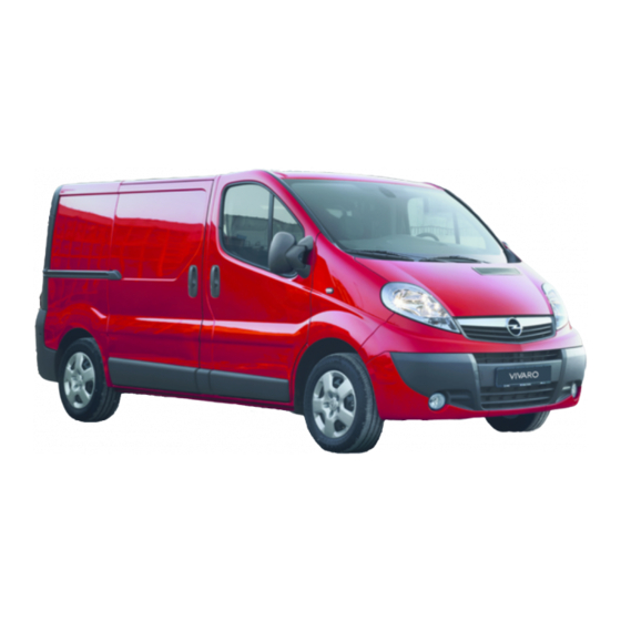
- Manuals
- Brands
- Opel Manuals
- Automobile
- VIVARO
- Manual
-
Contents
-
Table of Contents
-
Bookmarks
Related Manuals for Opel Vivaro
Summary of Contents for Opel Vivaro
-
Page 1: Table Of Contents
Contents Introduction ……..2 In brief ……….6 Keys, doors and windows …. 18 Seats, restraints ……30 Storage ……..51 Instruments and controls ….. 56 Lighting ……..74 Climate control ……79 Driving and operating ….84 Vehicle care ……. 106 Service and maintenance ..
-
Page 2: Introduction
Introduction Introduction…
-
Page 3
Introduction Vehicle specific data When this Owner’s Manual refers to ■ The Owner’s Manual uses the a workshop visit, we recommend your factory engine designations. The Please enter your vehicle’s data on Vauxhall Authorised Repairer. corresponding sales designations the previous page to keep it easily can be found in the section All Vauxhall Authorised Repairers accessible. -
Page 4
Introduction Danger, Warnings and Symbols Cautions Page references are indicated with 3. 3 means «see page». 9 Danger Thank you for choosing a Vauxhall. We wish you many hours of Text marked 9 Danger provides pleasurable driving. information on risk of fatal injury. Your Vauxhall Team Disregarding this information may endanger life. -
Page 5
Introduction… -
Page 6: In Brief
In brief In brief Vehicle unlocking Unlocking with radio remote control Unlocking with key Initial drive information Press button c, pull door handle. Turn the key in the driver’s door lock. Radio remote control 3 18, Central Open the doors by pulling the locking system 3 20, Load handles.
-
Page 7
In brief Seat adjustment Seat backrests Seat height Seat positioning Pull lever, adjust inclination and Lift lever and adjust body weight on release lever. Allow the seat to seat to raise or lower it. engage. Do not lean on backrest Pull handle, slide seat, release Seat position 3 31, Seat adjustment when adjusting. -
Page 8
In brief Head restraint adjustment Seat belt Mirror adjustment Interior mirror Raise or lower head restraint to the Pull out the seat belt and engage in desired height. belt buckle. The seat belt must not be twisted and must fit close against the To reduce dazzle, adjust the lever on Head restraints 3 30. -
Page 9
In brief Steering wheel adjustment Exterior mirrors Electric adjustment Manual adjustment Select the relevant exterior mirror and Unlock the lever, adjust the steering adjust it. wheel, then engage the lever and Swivel mirror in required direction. Convex exterior mirrors 3 26, ensure it is fully locked. -
Page 10
In brief… -
Page 11
In brief Instrument panel overview Centre air vents ….. 82 23 Power outlet ……60 Cigarette lighter ….. 60 10 Triple-Info-Display ….70 Ashtray ……..61 24 Ignition switch with 11 Infotainment system ….10 Cupholders ……51 steering wheel lock ….85 Tachograph …… -
Page 12
In brief Exterior lighting Front and rear fog lights Headlight flash, high beam and low beam Turn light switch Turn light switch Pull lever. = Front fog lights > = Off > r = Front and rear fog lights High beam 3 75, Headlight flash = Sidelights 3 75. -
Page 13
In brief Horn Turn and lane-change signals Hazard warning flashers lever up = right turn signal Operated with the ¨ button. Press j. lever down = left turn signal Hazard warning flashers 3 76. Turn and lane-change signals 3 76. -
Page 14
In brief Washer and wiper systems Windscreen and headlight Rear window wiper and washer washer systems system Windscreen wiper Pull lever. Turn lever. K = timed interval wiping short = wiper swipes once 0 = off = slow pull e = wiper = fast long = wiper swipes for a few… -
Page 15
In brief Climate control Transmission Demisting and defrosting the windows Heated rear window, heated Manual transmission exterior mirrors Air distribution to V. Reverse: with the vehicle stationary, Set temperature control to warmest wait 3 seconds after depressing Heating is operated by pressing the level. -
Page 16
In brief Starting off Manual transmission automated Starting the engine Check before starting off ■ Tyre pressure and condition 3 122, 3 151. ■ Engine oil level and fluid levels 3 108. ■ All windows, mirrors, exterior lighting and number plates are free from dirt, snow and ice and are operational. -
Page 17
In brief Parking ■ Do not park the vehicle on an easily ignitable surface. The high ■ Always apply parking brake without temperature of the exhaust system pushing the release button. Apply could ignite the surface. as firmly as possible on a downhill ■… -
Page 18: Keys, Doors And Windows
Keys, doors and windows Keys, doors and Keys, locks When the vehicle is taken to a workshop, this vehicle data is windows needed in order to perform certain Keys operations. Replacement keys Radio remote control Keys, locks ……..18 The key number is specified on the key or on a detachable tag.
-
Page 19
Keys, doors and windows The radio remote control has a range Replace the battery (battery type of approx. 16 ft. This range can be CR 2016), paying attention to the affected by outside influences. The installation position. hazard warning flashers confirm Reattach both halves of cover operation. -
Page 20
Keys, doors and windows Replace screw and tighten. Central locking system with radio Locking remote control Close doors, load compartment and Central locking system fuel filler flap. If the doors are not closed properly, the central locking Unlocks and locks doors, load system will not work. -
Page 21
Keys, doors and windows On vehicles with selective door Central locking button While the front doors are locked and locking only the passenger unlocked using the radio remote Locks or unlocks doors, the load compartment doors are locked. control, load compartment must be compartment and fuel filler flap from manually opened by turning the key in the passenger compartment. -
Page 22: Doors
Keys, doors and windows Doors Child locks cannot be opened from the inside. For deactivation, turn the child lock to the vertical position. Sliding door 9 Warning Ensure the side door is fully closed Use the child locks whenever and secure before driving the vehicle. children are occupying the rear The door can be locked from inside seats.
-
Page 23
Keys, doors and windows Load compartment Tailgate Opening The right hand rear door is released The doors are retained in the 90º using the lever. position by locking stays. To open the doors to 180º or further, pull the door 9 Warning release handles and swing open to the desired position. -
Page 24: Vehicle Security
Keys, doors and windows Vehicle security Closing Activating Close tailgate using the interior strap. Ensure tailgate is fully closed. Anti-theft locking system General hints for operating 9 Warning tailgate Do not use the system if there are 9 Warning people in the vehicle! The doors cannot be unlocked from the Do not drive with the tailgate open inside.
-
Page 25
Keys, doors and windows It monitors: Activation without monitoring of Deactivation passenger compartment Unlocking the vehicle deactivates the ■ Doors, tailgate, bonnet anti-theft alarm system. Turn signal ■ Passenger compartment including lights flash once upon deactivation. adjoining load compartment If the alarm has been triggered, the ■… -
Page 26: Exterior Mirrors
Keys, doors and windows Exterior mirrors The siren is silenced and the anti-theft Notice alarm system is deactivated by The immobiliser does not lock the pressing button c or by switching on doors. You should always lock the Convex shape the ignition.
-
Page 27
Keys, doors and windows Electric adjustment Folding Heated Select the relevant exterior mirror by For pedestrian safety, the exterior Operated by pressing the Ü button. turning the control to left or right. In mirrors will swing out of their normal Heating functions with the engine the central position no mirror is mounting position if they are struck… -
Page 28: Interior Mirrors
Keys, doors and windows Interior mirrors Windows Manual anti-dazzle Manual windows The door windows can be opened or closed with the window winders. Power windows 9 Warning Take care when operating the power windows. Risk of injury, Operate the control to open or close particularly to children.
-
Page 29
Keys, doors and windows Rear windows Heated rear window Sliding side windows Operated by pressing the Ü button. Heating functions with the engine To open, pull up catch and slide open. running and is switched off To close, pull up catch and slide automatically after a short time. -
Page 30: Seats, Restraints
Seats, restraints Seats, restraints Head restraints Adjustment Position Head restraints ……30 9 Warning Front seats ……..31 Rear seats ……..34 Only drive with the head restraint Seat belts ……..37 set to the proper position. Airbag system ……40 Child restraints ……
-
Page 31: Front Seats
Seats, restraints Front seats Head restraint removal ■ Sit with shoulders as far back against the backrest as possible. Set the backrest rake so that it is Seat position possible to reach the steering wheel with arms slightly bent. 9 Warning Maintain contact between shoulders and the backrest when Only drive with the seat correctly…
-
Page 32
Seats, restraints Seat adjustment Pull handle, slide seat, release Seat height handle. 9 Danger Seat backrests Do not sit nearer than 25 cm from the steering wheel, to permit safe airbag deployment. 9 Warning Never adjust seats while driving as they could move uncontrollably. -
Page 33
Seats, restraints Armrest Heating Lumbar support Adjust lumbar support using Adjust armrest support to suit Press the ß button for the respective handwheel to suit personal personal requirements. seat. Press the ß button again to requirements. switch off. ■ Raise armrest in increments to Rotate handwheel to increase and desired height. -
Page 34: Rear Seats
Seats, restraints Rear seats Seat heating is operational when the engine is running. Second row seats To enable long items to be stored under the seats the centre seat trim cover can be unclipped. When folding or removing the rear seat ensure the armrests are folded away in their most upright position.
-
Page 35
Seats, restraints Rear seat access Folding seats 9 Warning On some variants, the cargo area can be increased by folding up the rear When folding the seat use caution seats. — beware of moving parts. Ensure the seat is secure when completely folded. -
Page 36
Seats, restraints Raise the backrest, reinstall head With both catches raised, push the restraints and connect the seat belts. seat unit towards the rear and release them from the floor anchor points. 9 Warning The seat can then be lifted out. The seats must be removed through When installing the seat, ensure the sliding door only. -
Page 37: Seat Belts
Seats, restraints Seat belts Seat belts are only designed for use 9 Warning by one person at a time. They are not suitable for people younger than When re-installing seats always 12 years of age or smaller than 5 ft. ensure that the row with the folding Periodically check all parts of the belt access seat B is positioned…
-
Page 38
Seats, restraints Three-point seat belt 9 Warning Fitting Incorrect handling (e.g. removal or fitting of belts) can trigger the belt tensioners with risk of injury. Deployment of the belt tensioners is indicated by continuous illumination of control indicator v 3 66. Triggered belt tensioners must be replaced by a workshop. -
Page 39
Seats, restraints Height adjustment Removing Seat belts on the rear seats Two-latch belt 1. Pull belt out slightly. To release belt, press red button on belt buckle. 2. Press button. Before fitting the belt, first insert lower 3. Slide adjuster up or down to latch plate into the buckle on the desired position. -
Page 40: Airbag System
Seats, restraints Airbag system Using the seat belt while 9 Warning pregnant The airbag system consists of The seat belt will not be effective a number of individual systems in the event of an accident if the depending on the scope of lower latch is not correctly fitted.
-
Page 41
Seats, restraints Front airbag system Notice 9 Warning The airbag systems and belt The front airbag system consists of tensioner control electronics are one airbag in the steering wheel and Optimum protection is only located in the centre console area. one in the instrument panel on the provided when the seat is in the Do not put any magnetic objects in… -
Page 42
Seats, restraints Curtain airbag system The side airbag system consists of an airbag in each front seat backrest. This can be identified by the word AIRBAG. The inflated airbags cushion the impact, thereby reducing the risk of The curtain airbag system consists of injury to the upper body and pelvis in an airbag in the roof frame on each the event of a side-on collision… -
Page 43
Seats, restraints Airbag deactivation Front airbag and side airbag systems for the front passenger seat have to be deactivated if a child restraint system is to be fitted on this seat. The curtain airbag system, the belt tensioners and all driver airbag systems will remain active. -
Page 44: Child Restraints
Seats, restraints Child restraints 9 Danger 9 Warning Child restraint systems Risk of fatal injury for a child using When using a child restraint a child restraint system together system on the front passenger We recommend the Vauxhall child with activated front passenger seat, the airbag systems for the restraint system which is tailored airbag.
-
Page 45
Seats, restraints Since a proper position of the seat Notice belt is rarely possible with a child that Do not stick anything on the child is smaller than 5 ft, we strongly advise restraint systems and do not cover the use of an appropriate child them with any other materials. -
Page 46
Seats, restraints Child restraint installation locations Permissible options for fitting a child restraint system Front seats — all variants Weight and age class Single seat — front passenger Bench seat — front passenger without airbag with airbag without airbag with airbag centre outer centre… -
Page 47
Seats, restraints = Suitable for universal category restraint systems for use in this weight and age class, in conjunction with three-point seat belt. UF = Suitable for universal category forward-facing restraint systems for use in this weight and age class, in conjunction with three-point seat belt. -
Page 48
Seats, restraints U = Suitable for universal category restraint systems for use in this weight and age class, in conjunction with three-point seat belt. < = Seat with ISOFIX mounting available. When mounting an ISOFIX child restraint system, only systems that have been approved for the vehicle may be used. -
Page 49
Seats, restraints U = Suitable for universal category restraint systems for use in this weight and age class, in conjunction with three-point seat belt. < = Seat with ISOFIX mounting available. When mounting an ISOFIX child restraint system, only systems that have been approved for the vehicle may be used. -
Page 50
Seats, restraints Isofix child restraint systems Fasten vehicle-approved ISOFIX child restraint systems to the ISOFIX mounting brackets. When using ISOFIX mounting brackets for seat mounting, universally approved child restraint systems for ISOFIX may be used. Permissible mounting location positions for ISOFIX child restraint systems are marked in the tables by <. -
Page 51: Storage
Storage Storage Storage compartments Glovebox cooler 3 83. Instrument panel storage Cupholders Storage compartments, pockets and Storage compartments ….51 trays are located in the instrument Load compartment ……. 52 panel. Roof rack system ……54 A coin holder and a phone pocket are Loading information …..
-
Page 52: Load Compartment
Storage Load compartment Overcab storage Load rails and hooks Load compartment cover Do not place any objects on the cover. Removing The total weight in this compartment Load anchorage rails mounted in the must not exceed 30 kg. load compartment provide adjustable anchorage points for securing cargo.
-
Page 53
Storage ■ cargo can then be secured in The maximum force applied to the position using lashing straps lashing eyes should not exceed attached to the anchorage point. 5000 N at 30°. The maximum load of each Safety net anchorage point is 75 kg. To prevent the possibility of exceeding this The safety net can be installed behind maximum, the use of ratchet type… -
Page 54: Roof Rack System
Storage Roof rack system Loading information vehicle weight (see identification plate 3 140) and the EC kerb weight. Roof rack ■ Heavy objects in the load To calculate the EC kerb weight, compartment should be placed as For safety reasons and to avoid enter the data for your vehicle in the far forward as possible.
-
Page 55
Storage and 210 kg for high roof variants (excludes Platform cab conversions). The roof load is the combined weight of the roof rack and the load. The permissible roof load on the approved full length roof rack system is 210 kg for standard roof variants and 140 kg for high roof variants (excludes Platform cab conversions). -
Page 56: Instruments And Controls
Instruments and controls Instruments and Controls Steering wheel controls controls Steering wheel adjustment Controls ……..56 Warning lights, gauges and indicators ……..61 Information displays ….. 70 Vehicle messages ……70 Trip computer ……. 71 Tachograph ……..73 The cruise control and speed limiter can be operated via the controls on the steering wheel.
-
Page 57
Instruments and controls Horn Steering column controls Windscreen wiper/washer Windscreen wiper Press j. The Infotainment system can be operated via the controls on the The horn will sound regardless of K = timed interval wipe steering column. ignition switch position. = slow Further information is available in the = fast… -
Page 58
Instruments and controls Automatic wiping with rain sensor Adjustable sensitivity of the rain Windscreen washer sensor Turn the adjuster wheel to adjust the sensitivity: = turn adjuster wheel sensitivity downwards high = turn adjuster wheel sensitivity upwards K = automatic wiping with rain Pull lever. -
Page 59
Instruments and controls Rear window wiper/washer Outside temperature 9 Warning The road surface may already be icy even though the display indicates a few degrees above 0 °C. Clock Turn: A drop in temperature is indicated immediately and a rise in temperature 0 = off after a time delay. -
Page 60
Instruments and controls Power outlets Caution Do not damage the outlet by using unsuitable plugs. Cigarette lighter Connecting electrical accessories while the engine is off will discharge 12 V power outlets are located in the the battery. Do not exceed the instrument panel and in the rear of the maximum power consumption of vehicle. -
Page 61: Warning Lights, Gauges And Indicators
Instruments and controls Warning lights, gauges Ashtrays Notice Under certain conditions (e.g. steep and indicators inclines) the vehicle speed may Caution exceed the set limit. Speedometer Odometer To be used only for ash and not for combustible rubbish. Portable ashtray Indicates vehicle speed.
-
Page 62
Instruments and controls Fuel gauge Engine oil level monitor seconds with the ignition on. The display will flash and the value will The engine oil level monitor is correct reset to zero. only if the vehicle is parked on a level surface with a cold engine. -
Page 63
Instruments and controls Transmission display ⃞ ⃞ ⃞ ⃞ ⃞ = Maximum level Information Centre respectively, and ⃞ the corresponding message ⃞ ⃞ ⃞ _ _ = Intermediate SERVICE DUE appears in the Driver _ level Information Centre. _ _ _ _ _ = Minimum level. -
Page 64
Instruments and controls Control indicators The control indicators described are not present in all vehicles. The description applies to all instrument versions. When the ignition is switched on, most control indicators will illuminate briefly as a functionality test. The control indicator colours mean: = danger, important reminder yellow = warning, information, fault… -
Page 65
Instruments and controls Control indicators in the instrument cluster… -
Page 66
Instruments and controls Turn signal whilst driving, there is a fault in the 9 Danger belt tensioner or the airbag system. O flashes green. The airbags and belt tensioners may Risk of fatal injury for a child using Flashes if a turn signal or the hazard fail to trigger in the event of an a child restraint system together warning flashers are activated. -
Page 67
Instruments and controls Malfunction indicator light May illuminate in combination with If the message BRAKING FAULT another control indicator or appears in the Driver Information Z illuminates or flashes yellow. a message in the Driver Information Centre there is a fault in the braking Illuminates when the ignition is Centre. -
Page 68
Instruments and controls Diesel particle filter Driver Information Centre. Seek the ESP® Plus 3 95. assistance of a workshop 8 illuminates yellow. immediately. Engine coolant Illuminates when the diesel particle Antilock brake system 3 93. temperature filter requires cleaning 3 86. W illuminates red. -
Page 69
Instruments and controls Exterior light 3. Move out of the flow of traffic as m illuminates green when a certain quickly as possible without speed is stored. 9 illuminates green. impeding other vehicles. U illuminates green when the system Illuminated when the exterior lights 4. -
Page 70: Information Displays
Instruments and controls Information displays Vehicle messages ■ Vehicle messages 3 70 ■ Trip computer 3 71 Driver Information Center Messages are shown in the Driver Triple-Info-Display Information Centre, in combination The Driver Information Centre is with illumination of control indicator located in the instrument cluster Displays time, outside temperature A or C in the instrument cluster.
-
Page 71: Trip Computer
Instruments and controls Trip computer Warning chimes remains illuminated. The fault will then be stored in the on board system. When starting the engine or The trip computer provides whilst driving information on driving data, which is Fault messages continually recorded and evaluated ■…
-
Page 72
Instruments and controls ■ Range Instantaneous consumption The average speed is displayed, since the last reset. The value is displayed after reaching ■ Distance travelled a speed of 20 mph. The measurement can be restarted at ■ Average speed any time. ■… -
Page 73: Tachograph
Instruments and controls Tachograph Interruption of power supply If the power supply has been interrupted or if the battery voltage has dropped too low, the values stored in the trip computer will be lost. The tachograph is operated as described in the operating instructions supplied.
-
Page 74: Lighting
Lighting Lighting Exterior lighting Automatic light control Light switch Exterior lighting ……74 Interior lighting ……77 Lighting features ……78 When the engine is running, headlights are switched on when external light conditions are poor. Turn light switch: To activate: = Off = Sidelights 1.
-
Page 75
Lighting Headlight range Headlights when driving For reasons of safety, it is advisable to have the function activated. adjustment abroad During poor lighting conditions, e.g. The asymmetrical headlight beam fog or mist, manually switch on the Manual headlight range extends visibility at the edge of the headlights. -
Page 76
Lighting Hazard warning flashers Turn and lane-change If the lever is moved past the first stop, the indicator is switched on signals constantly. Switch the indicator off manually by moving the lever to its original position. Front fog lights Operated with the ¨ button. Lever up = right turn signal Lever down = left turn signal… -
Page 77
Lighting Interior lighting Load compartment lighting Rear fog light comes on in conjunction with front fog lights and The lighting can be switched on when will only operate when the ignition and Interior lights the load compartment is opened. headlights are switched on. Reversing lights The reversing lights come on when the ignition is on and reverse gear is… -
Page 78
Lighting Lighting features This action can be repeated up to four times to a maximum period of 2 minutes. Exit lighting The lighting is turned off immediately by switching on the ignition or turning the light switch. Operated by tilting the lens to one of 3 positions: ■… -
Page 79: Climate Control
Climate control Climate control Climate control systems Heating will not be fully effective until the engine has reached normal operating temperature. Heating and ventilation system Fan speed Climate control systems ….79 Adjust the air flow by switching the fan Air vents ……..
-
Page 80
Climate control ■ Open side air vents as required and Cooling (AC) Maximum cooling direct them towards door windows. Operated with the AC button and Briefly open the windows so that hot functional only when the engine and air can disperse quickly. ■… -
Page 81
Climate control Rear air conditioning The rear passenger compartment The rate of air flow is determined by heating fan assists air flow to the rear the fan. system passenger compartment via the rear The fan has 3 speeds: air vents. The rear air conditioning system is 0 = off actuated in conjunction with the front… -
Page 82
Climate control Air vents Side air vents Rear passenger compartment air vents Adjustable air vents At least one air vent must be open while cooling is on in order to prevent the evaporator from icing up due to lack of air movement. Centre air vents To open or close the side air vents, turn the adjuster wheel left or right. -
Page 83
Climate control Maintenance Glovebox cooler Service For optimal cooling performance, it is Air intake recommended that the climate control system be checked annually, starting The air intake in front of the three years after initial vehicle windscreen in the engine registration, including: compartment must be kept clear to allow air intake. -
Page 84: Driving And Operating
Driving and operating Driving and operating Driving hints Starting and operating Control of the vehicle New vehicle running-in Do not brake unnecessarily hard for Driving hints ……… 84 Never coast with engine not the first few journeys and after new Starting and operating ….
-
Page 85
Driving and operating Ignition switch positions Starting the engine The increased engine speed automatically returns to normal idling speed as the engine temperature rises. Start attempts should not last longer than 15 seconds. If engine does not start, wait 15 seconds before repeating starting procedure. -
Page 86: Engine Exhaust
Driving and operating Engine exhaust uphill slopes. Operate the foot consumption may be higher during brake at the same time to reduce this period. The emission of smells operating force. and smoke during this process is normal. 9 Danger ■ Switch off the engine and ignition. Turn the steering wheel until the Engine exhaust gases contain steering wheel lock is felt to…
-
Page 87
Driving and operating Stopping the journey or switching off Malfunction indicator light 3 67 Caution the engine during cleaning is not recommended. Fuel grades other than those listed on pages 3 101, 3 142 could Caution damage the catalytic converter or electronic components. -
Page 88: Manual Transmission
Driving and operating Manual transmission Manual transmission Caution automated It is inadvisable to drive with hand resting on the selector lever. The Easytronic transmission permits manual (manual mode) or automatic gear shifting (automatic mode), both with automatic clutch control. Transmission display To engage reverse, with the vehicle stationary depress the clutch pedal, pull up the collar on the selector lever…
-
Page 89
Driving and operating Starting the engine Always move the selector lever in the start off quickly, release the foot brake appropriate direction as far as it will and accelerate immediately after Depress the foot brake when starting go. Upon release, it automatically engaging a gear. -
Page 90
Driving and operating warning may sound as a signal to Rocking the vehicle If engine speed is too low, the depress the foot brake or apply the transmission automatically shifts to Rocking the vehicle is only parking brake. a lower gear. permissible if the vehicle is stuck in sand, mud, snow or a hole. -
Page 91
Driving and operating Activation Laden mode kg Deactivation Press the V button. V is shown in the The Laden mode is switched off by: transmission display. The ■ pressing the kg button again, transmission switches to automatic ■ turning off the ignition. mode and the vehicle starts off in a suitable gear. -
Page 92: Brakes
Driving and operating Brakes If engine speed is too high the If neutral cannot be selected, the transmission switches to a higher vehicle must only be towed with the gear, even in manual mode. Without drive wheels raised off the ground. The brake system comprises two kickdown this automatic shift is not Towing the vehicle 3 132.
-
Page 93
Driving and operating Parking brake Control indicator R 3 67. illuminate in the instrument cluster together with the messages CHECK Vehicle messages 3 70. ABS and CHECK ESP in the Driver Information Centre. The brake Antilock brake system system remains operational but without ABS regulation. -
Page 94: Ride Control Systems
Driving and operating Ride control systems Brake assist 9 Warning If the brake pedal is depressed Traction Control system quickly and forcefully, maximum Do not let this special safety brake force is automatically applied feature tempt you into taking risks The Traction Control system (TC) is (full braking).
-
Page 95
Driving and operating Electronic stability Press the v button. Control indicator 9 Warning v illuminates in the instrument cluster program and the message ESP OFF appears Do not let this special safety in the Driver Information Centre. The Electronic Stability Program feature tempt you into taking risks (ESP®… -
Page 96: Cruise Control
Driving and operating Cruise control Press the v button. Control indicator Activation v illuminates in the instrument cluster and the message ESP OFF appears The cruise control can store and in the Driver Information Centre. maintain speeds of 20 mph and ESP®…
-
Page 97
Driving and operating Increase speed With cruise control active, the vehicle speed can be increased continuously or in small increments by holding down or tapping switch < repeatedly. When the switch is released the current speed is stored and maintained. Alternatively, accelerate to the desired speed and store by pressing switch <. -
Page 98
Driving and operating Deactivation Resume stored speed Activation Press switch R at a speed above 20 mph. If the stored speed is much higher than the current speed, the vehicle will accelerate powerfully until the stored speed is obtained. Deleting the stored speed Press switch m: Green control indicators U and m extinguish in the instrument cluster. -
Page 99: Object Detection Systems
Driving and operating Object detection Where the limit speed cannot be Deactivation maintained, e.g. when driving on Press switch §: speed limiter is systems a steep decline, the limit speed will deactivated and the vehicle can be flash in the Driver Information Centre. driven normally.
-
Page 100
Driving and operating Notice Deactivation Permanent deactivation Attached parts in the detection area Permanently deactivate the system cause system malfunction. by pressing and holding the E button on the instrument panel for approx. Activation 3 seconds with the ignition on and When reverse gear is engaged, the reverse gear engaged. -
Page 101: Fuel
Driving and operating Fuel a biodiesel (= FAME according to Caution EN14214) content of max. 10% by volume (like DIN 51628 or equivalent Fuel for petrol engines When reversing, the area should standards) may be used. be free from obstacles which could Only use unleaded fuel that complies Do not use marine diesel oils, heating impact on the underside of the…
-
Page 102
Driving and operating Refuelling The fuel filler flap can only be opened Fault if the vehicle is unlocked. Should an interruption to the power supply occur, central locking will not 9 Danger unlock the fuel filler flap. In such cases release manually. Before refuelling, switch off engine and any external heaters with combustion chambers (identified… -
Page 103
Driving and operating To open If the cause of the interruption to the higher fuel consumption and CO power supply is not a discharged emission levels and a lower maximum battery, consult a workshop. speed. Fuel consumption — CO Emissions The determination of fuel consumption is regulated by European directive 80/1268/EEC… -
Page 104: Towing
Driving and operating Towing A maximum speed of 50 mph must The permissible trailer loads are not be exceeded, even in countries specified in the vehicle documents. In where higher speeds are permitted. general, they are valid for gradients General information up to max.
-
Page 105
Driving and operating The maximum permissible vertical Towing equipment audible coupling load is specified on the warning towing equipment identification plate For vehicles fitted with towing and in the vehicle documents. Always equipment, when connected to aim for the maximum load, especially a trailer the pitch of the audible in the case of heavy trailers. -
Page 106: Vehicle Care
Vehicle care Vehicle care General Information ■ Change engine oil. ■ Drain washer fluid reservoir. Accessories and vehicle ■ Check coolant antifreeze. modifications ■ Adjust tyre pressure to the value General Information ….106 specified for full load. We recommend the use of Genuine Vehicle checks ……
-
Page 107: Vehicle Checks
Vehicle care Vehicle checks Bonnet ■ Fill up the washer fluid reservoir. ■ Check the engine oil level. Performing work Opening ■ Check the coolant level. ■ Fit the number plate, if necessary. 9 Warning End-of-life vehicle Only perform engine compartment recovery checks when the ignition is off.
-
Page 108
Vehicle care Closing Caution Before closing the bonnet, press the support into the holder. It is the owner’s responsibility to Lower the bonnet and allow it to drop maintain the proper level of an into the catch. Check that the bonnet appropriate quality oil in the is engaged. -
Page 109
Vehicle care For M9R engines, rotate cap anticlockwise, remove the dipstick, wipe it clean and re-insert it as far as it will go. On F9Q engines, the dipstick is We recommend the use of the same mounted on the oil filler cap which type of engine oil that was used at the must be rotated anticlockwise to last change. -
Page 110
Vehicle care Capacities 3 150, Engine oil level monitor 3 62. Fit the cap on straight and tighten it. Engine air filter Engine air flow indicator To prevent spillage when Remove the caps and ensure funnel replenishing the engine oil on F9Q is securely located onto the filler pipe. -
Page 111
Vehicle care If the red tell-tale is displayed when concentration checked and have the the engine is running, consult cause of the coolant loss remedied by a workshop. a workshop. If a substantial amount of coolant is Engine coolant required, it will be necessary to bleed any trapped air from the cooling The coolant provides freeze system. -
Page 112
Vehicle care Brakes If the fluid level in the reservoir falls below the MIN mark consult A squealing noise indicates that the a workshop. brake lining is at its minimum thickness. Continued driving is Washer fluid possible but have the brake lining replaced as soon as possible. -
Page 113
Vehicle care Diesel fuel filter Batteries do not belong in household Replacing the battery waste. They must be disposed of at When the battery is being replaced, an appropriate recycling collection please ensure that there are no open point. ventilation holes in the vicinity of the positive terminal. -
Page 114
Vehicle care Diesel fuel system 4. Manually operate the in-line Wiper blade on the rear window supply pump slowly and steadily Lift wiper arm, rotate wiper blade and bleeding until fuel discharging from the detach. loosened vent screw is free of air bubbles. -
Page 115: Bulb Replacement
Vehicle care Bulb replacement 1. Remove harness connector. 1. Remove bulb holder from reflector housing by rotating through 90°. 2. Remove rubber seal. 2. Renew bulb. Switch off the ignition and turn off the 3. Release retaining clip and remove relevant switch or close the doors.
-
Page 116
Vehicle care Side turn signal lights 1. Remove bulb holder from reflector housing by rotating through 90°. 2. Renew bulb. 3. Install bulb holder in reflector housing. Tail lights Rear brake, turn signal and tail lights 3. Twist bulb holder to separate from lamp assembly. -
Page 117
Vehicle care Reversing light Number plate light Fog tail light 1. Remove 2 screws (using the tool 1. Remove 2 screws (arrowed) and 1. Remove 2 screws (using the tool supplied) and remove lamp remove lens. supplied) and remove lamp assembly. -
Page 118
Vehicle care Interior lights Instrument panel Load compartment light illumination Front courtesy light Have bulbs replaced by a workshop. 1. Remove lamp assembly using a flat blade screwdriver. 1. Remove lens using a flat blade 2. Gain access to bulb by removing screwdriver. -
Page 119: Electrical System
Vehicle care Electrical system Fuse extractor Fuses Data on the replacement fuse must match the data on the defective fuse. The fuse box is located on the left- hand side of the instrument panel, below the cupholder. Before replacing a fuse, turn off the respective switch and the ignition.
-
Page 120
Vehicle care Instrument panel fuse box Some circuits may be protected by several fuses. Symbol Application Air conditioning Heated exterior mirrors Heated front seats Power windows Left-hand high beam Right-hand high beam To help in replacing fuses, a fuse extractor is located in the fuse box. Windscreen wiper Located on the left-hand side of the Place the fuse extractor on the… -
Page 121: Vehicle Tools
Vehicle care Vehicle tools Symbol Application Symbol Application Heating Front fog lights > Tools Interior lamp Power outlet Antilock brake system Tachograph Heated rear windows Ü Clock, interior lights, radio, Infotainment system Fuel injection system Rear window washer Rear widow wiper The jack, adapters, ratchet, torx key, Left-hand sidelight hub cap hook, towing eye and spare…
-
Page 122: Wheels And Tyres
Vehicle care Wheels and tyres Tyre pressure In accordance with country-specific regulations, a notice indicating the Check the pressure of cold tyres at maximum permissible speed for the least every 14 days and before any Tyre condition, wheel condition tyres must be affixed within the long journey.
-
Page 123
Vehicle care Tyres should be replaced for safety Tyres age, even if they are not used. If the wheel covers and tyres used are reasons at a tread depth of 2-3 mm We recommend tyre replacement not factory approved, the tyres must (4 mm for winter tyres). -
Page 124
Vehicle care Tyre repair kit Tyre chains are only permitted on the front wheels. Minor damage to the tyre tread or Always use fine mesh chains that add sidewall can be repaired with the tyre no more than 15 mm to the tyre tread repair kit. -
Page 125
Vehicle care 9. Set the rocker switch on the 3. Screw the compressor air hose to 6. Screw the filler hose to the tyre compressor to I. The tyre is filled the connection on the sealant valve. with sealant. bottle. 7. -
Page 126
Vehicle care damaged. Seek the assistance of a workshop. Drain excess tyre pressure with the button above the pressure indicator. Do not run the compressor for longer than 10 minutes. 13. Detach the tyre repair kit. Screw the tyre inflation hose to the free connection on the sealant bottle. -
Page 127
Vehicle care Wheel changing the vehicle must not be driven. Notice Seek the assistance of The driving characteristics of the Some vehicles are equipped with a workshop. repaired tyre is severely affected, a tyre repair kit instead of a spare therefore have this tyre replaced. -
Page 128
Vehicle care ■ Never crawl under a jacked-up Put wheel bolts somewhere vehicle. where the threads will not be soiled. ■ Do not start the engine when the vehicle is raised on the jack. 6. Change the wheel. ■ Before screwing in the wheel bolts, 7. -
Page 129
Vehicle care Use of a spare wheel that is smaller Summer and winter tyres 9 Warning than the other wheels or together with If you use winter tyres, the spare winter tyres could affect driveability. wheel may still be fitted with Due to the weight of the tyre Have the defective tyre replaced as a summer tyre. -
Page 130
Vehicle care A vehicle with a discharged battery ■ Use a booster battery with the Battery access can be started using jump leads and same voltage (12 volts). Its capacity the battery of another vehicle. (Ah) must not be much less than that of the discharged battery. -
Page 131
Vehicle care Lead connection order: 3. Allow both engines to idle for approx. 3 minutes with the leads 1. Connect the red lead to the connected. positive terminal of the booster battery. 4. Switch on electrical consumers (e.g. headlights, heated rear 2. -
Page 132: Towing
Vehicle care Towing Towing another vehicle Switch on ignition to release steering wheel lock and to permit operation of brake lights, horn and windscreen Towing the vehicle wipers. Transmission in neutral. If neutral cannot be selected on vehicles with MTA transmission, the vehicle must only be towed with the drive wheels raised off the ground.
-
Page 133: Appearance Care
Vehicle care Appearance care Vehicles with a towing hitch have If using a vehicle wash, comply with a socket for the detachable towing the vehicle wash manufacturer’s eye. Screw the towing eye, supplied instructions. The windscreen wipers Exterior care with the vehicle tools, fully into the and rear window wiper must be socket.
-
Page 134
Vehicle care Exterior lights For mechanical removal of ice, use After the underbody is washed, check a sharp-edged ice scraper. Press the the underbody and have it waxed if Headlight and other light covers are scraper firmly against the glass so necessary. -
Page 135
Vehicle care Do not use high-pressure jet Caution cleaners. Close Velcro fasteners as open Towing equipment Velcro fasteners on clothing could Do not clean the coupling ball bar with damage seat upholstery. a steam-jet or high-pressure jet cleaner. Plastic and rubber parts Plastic and rubber parts can be Interior care cleaned with the same cleaner as… -
Page 136: Service And Maintenance
Service and maintenance Service and General information European service intervals — M9R 630 engine only maintenance Service information Maintenance of your vehicle is required every 25,000 miles or after In order to ensure economical and 1 year, whichever occurs first, unless safe vehicle operation and to otherwise indicated by the service General information ….
-
Page 137
Service and maintenance Recommended fluids, service is essential if any warranty or The quality specification indicates its goodwill claims are to be met, and is ability to protect the engine from lubricants and parts also a benefit when selling the wear, whilst the viscosity grade vehicle. -
Page 138
Service and maintenance Topping up engine oil Multigrade oil is indicated by two problems. Liability for consequences figures. The first figure, followed by resulting from the use of additional Engine oils of different manufacturers a W, indicates the low temperature coolant additives will be rejected. -
Page 139: Technical Data
Technical data Technical data Vehicle identification Vehicle Identification Number Vehicle identification ….139 Vehicle data ……. 142 The VIN is also displayed behind a removable plastic cover on the right hand side door step. The Vehicle Identification Number is visible through the windscreen.
-
Page 140
Technical data Identification plate The combined total of front and rear axle loads must not exceed the permissible gross vehicle weight. For example, if the front axle is bearing its maximum permissible load, the rear axle can only bear a load that is equal to the gross vehicle weight minus the front axle load. -
Page 141
Technical data Engine identification It is possible, using the Vehicle Identification Number (VIN), to determine the engine type that is installed in your vehicle. The seventh digit denotes the engine type: Digit Engine P or S: 2.0 Diesel, M9R 630 L, N or W: 2.0 Petrol, F4R 820 1.9 Diesel, F9Q 760… -
Page 142
Technical data Vehicle data Engine data Sales designation F4R 820 F9Q 760 Engine identifier code M9R 630 Number of cylinders 1998 1870 1995 Piston displacement [cm Engine power [kW] 66 / 84 at rpm 4700 3500 3500 Torque [Nm] 260 / 300 at rpm 3750 1800… -
Page 143
Technical data Sales designation M9R 786 M9R 786 Engine identifier code M9R 788 G9U 630 Number of cylinders 1995 1995 2464 Piston displacement [cm Engine power [kW] 84 / 107 at rpm 3500 3500 3500 Torque [Nm] 290 / 310 at rpm 1600 2100… -
Page 144
Technical data Vehicle weight Kerb weight, basic model Model Wheelbase Roof Payload Class Engine Kerb weight Short Standard 1000 1660 1660 1678 1736 Standard 1200 1660 1669 1688 1737 High 1200 1695 1713 1760 1810 Kerb weight and gross vehicle weight increase on models fitted with bad road equipment package — refer to VIN plate. -
Page 145
Technical data Model Wheelbase Roof Payload Class Engine Kerb weight Long Standard 1200 1660 1676 1724 1772 High 1200 1745 1761 1810 1860 Kerb weight and gross vehicle weight increase on models fitted with bad road equipment package — refer to VIN plate. -
Page 146
Technical data Model Wheelbase Roof Payload Class Engine Kerb weight Combi Short Standard 1000 1818 1835 1883 1940 Standard 1200 1829 1846 1893 1942 Long Standard 1200 1890 1906 1954 2003 Kerb weight and gross vehicle weight increase on models fitted with bad road equipment package — refer to VIN plate. -
Page 147
Technical data Model Wheelbase Roof Payload Class Engine Kerb weight Platform cab Long Standard 1200 1449 1467 1515 1563 Tour Short Standard 1879 1944 2018 Kerb weight and gross vehicle weight increase on models fitted with bad road equipment package — refer to VIN plate. Vehicle without body conversion. -
Page 148
Technical data Vehicle dimensions Type Combi/Tour Platform cab Wheelbase Short Long Short Long Long Length [mm] 4782 5182 4782 5182 5130 Width without exterior mirrors [mm] 1904 1904 1904 1904 1904 Width with two exterior mirrors [mm] 2232 2232 2232 2232 2232/2434 Height — unladen (without antenna) [mm]… -
Page 149
Technical data Loadspace dimensions Wheelbase Short Long Roof height Standard High Standard High Maximum rear door aperture height [mm] 1335 1818 1335 1818 Rear door aperture width (at floor) [mm] 1390 1390 1390 1390 Maximum load area height [mm] 1387 1913 1387 1913… -
Page 150
Technical data Capacities Engine oil Engine Engine oil including filter [l] between MIN and MAX [l] 1.5 — 2.0 1.5 — 2.0 1.5 — 2.0 1.5 — 2.0 Fuel tank Engine Fuel tank, nominal capacity [l]… -
Page 151
Technical data Tyre pressures Tyre Tyre pressure with full load Front Rear [kPa/bar] (psi) [kPa/bar] (psi) 195/65 R16 C 340/3.4 (49) 370/3.7 (54) 195/75 R16 C 380/3.8 (55) 420/4.2 (61) 205/65 R16 C 380/3.8 (55) 420/4.2 (61) 215/65 R16 C 310/3.1 (45) 340/3.4 (49) The spare wheel should be set to the highest applicable pressure shown in the table. -
Page 152
Technical data Towing hitch installation dimensions… -
Page 153: Customer Information
Customer information Customer information Vehicle data recording ■ with the consent of the vehicle owner or, if the vehicle is leased, and privacy with the consent of the lessee, ■ in response to an official request of Event data recorders Vehicle data recording and police or similar government office, privacy ……..
-
Page 154: Index
Index Accessories and vehicle Capacities ……..150 modifications ……106 Car Pass ……..18 Adjustable air vents ….. 82 Catalytic converter ……. 87 Airbag and belt tensioners … 66 Central locking system ….20 Airbag deactivation ….43, 66 Centre high-mounted brake Airbag system ……
-
Page 155
Door open ……..69 Fog tail light ……. 117 Heating ……..33 Driver Information Center …. 70 Folding ……… 27 Heating and ventilation system . . . 79 Driving characteristics and Front airbag system ….. 41 High beam ……69, 75 towing tips …… -
Page 156
Load compartment lighting… 77 Parking brake ……93 Seat position …….. 31 Loading information ….. 54 Performing work ……107 Second row seats ……34 Load rails and hooks ….52 Pollen filter ……..83 Selector lever ……. 89 Low fuel ……..69 Power outlets ……. -
Page 157
Towing hitch installation Vehicle unlocking ……6 dimensions ……152 Vehicle weight ……144 Towing the vehicle ….. 132 Traction Control system ….94 Warning chimes ……71 Trailer towing ……104 Warning triangle ……53 Transmission ……. 15 Washer and wiper systems ..14 Transmission display …..
Руководство по ремонту и эксплуатации Renault Trafic / Opel Vivaro / Nissan Primastar с 2001 года выпуска с бензиновыми и дизельными двигателями.
Руководство содержит рекомендации по техническому обслуживанию, ремонту двигателей, трансмиссии, ходовой части, рулевого управления с гидроусилителем, тормозных систем с ABS, электрооборудования, элементов кузова.
Руководство предназначено для автовладельцев Renault Trafic, Opel Vivaro, Nissan Primastar, механиков, персонала СТО и ремонтных мастерских.
Издательство: Вильнюс
Год издания: 2006
Тип: электронное руководство
Язык: русский
Формат: PDF
Страниц: 208
Размер: 116,7 Мб
Автомобили:
Renault Trafic, Opel Vivaro, Nissan Primastar с 2001 г. выпуска.
Двигатели:
Бензиновые двигатели:
F4R 2.0 16V — 88 кВт (120 л.с.).
Дизельные двигатели:
F9Q 760/762 1.9 dCi — 58-74 кВт (79-100 л.с.);
G9U 730 2.5 dCi — 98 кВт (134 л.с.).
Содержание:
1. РУКОВОДСТВО ПО ЭКСПЛУАТАЦИИ
2. БЕНЗИНОВЫЙ ДВИГАТЕЛЬ F4R720 2.0 16V
1. Затяжка головки блока цилиндров
2. Регулировка ремня привода вспомогательного оборудования двигателя
3. Объемы рабочих жидкостей
4. Проверка давления масла
5. Снятие и установка двигателя
6. Снятие и установка ремня ГРМ
7. Технические данные двигателя
8. Технические характеристики элементов системы впрыска топлива
СИСТЕМА ВПУСКА ВОЗДУХА
9. Снятие и установка корпуса дроссельной заслонки
10. Снятие и установка впускного коллектора
11. Снятие и установка выпускного коллектора
12. Снятие и установка топливной рейки и форсунок
13. Снятие и установка поршней и шатунов
14. Снятие и установка датчиков кислорода
14.1. Датчик кислорода перед катализатором
14.2. Датчик кислорода после катализатора
15. Снятие и установка датчика положения педали акселератора
15.1. Автомобили с левосторонним рулевым управлением
15.2. Автомобили с правосторонним рулевым управлением
16. Снятие и установка датчика частоты вращения коленчатого вала
17. Снятие и установка датчика температуры охлаждающей жидкости
18. Снятие и установка датчика температуры всасываемого воздуха
19. Снятие и установка датчика детонации
СИСТЕМА ПОДЗАРЯДКИ БАТАРЕИ
20. Снятие и установка генератора
СИСТЕМА ЗАПУСКА ДВИГАТЕЛЯ
21. Снятие и установка стартера
СИСТЕМА ЗАЖИГАНИЯ
22. Снятие и установка катушки зажигания
СИСТЕМА ОХЛАЖДЕНИЯ
23. Снятие и установка радиатора системы охлаждения
3. ДИЗЕЛЬНЫЙ ДВИГАТЕЛЬ 1.9 DCI F9Q 760/762
1. Давление масл
2. Снятие и установка двигателя и коробки передач
3. Снятие и установка натяжного ролика ремня ГРМ
4. Снятие и установка ремня ГРМ
5. Снятие и установка прокладки головки блока цилиндров
СИСТЕМА ВПУСКА ВОЗДУХА
6. Замена фильтрующего элемента воздушного фильтра
7. Снятие и установка коллекторов
8. Снятие и установка расходомера воздуха
ТУРБОНАДДУВ
9. Клапан регулировки давления наддува
10. Регулировка давления наддува
11. Снятие и установка турбокомпрессора
12. Снятие и установка радиатора охлаждения наддувочного воздуха (интеркулер)
СИСТЕМА ВПРЫСКА ТОПЛИВА
13. Технические характеристики элементов системы впрыска топлива
14. Снятие и установка топливоподкачивающего насоса
15. Снятие и установка топливного фильтра
16. Снятие и установка топливного насоса высокого давления
17. Снятие и установка аккумулятора высокого давления
18. Снятие и установка форсунок
19. Снятие и установка датчика давления топлива
20. Снятие и установка датчика положения педали акселератора
21. Централизованное управление температурой охлаждающей жидкости
22. Снятие и установка блока управления системой впрыска топлива
СИСТЕМА ВЕНТИЛЯЦИИ КАРТЕРА
СИСТЕМА РЕЦИРКУЛЯЦИИ ОТРАБОТАВШИХ ГАЗОВ
СИСТЕМА ПОДЗАРЯДКИ АККУМУЛЯТОРНОЙ БАТАРЕИ
23. Снятие и установка генератора
СИСТЕМА ЗАПУСКА ДВИГАТЕЛЯ
24. Снятие и установка стартера
СИСТЕМА ОХЛАЖДЕНИЯ
4. ДИЗЕЛЬНЫЙ ДВИГАТЕЛЬ 2.5 DCI G9U 730
1. Давление масла
2. Снятие и установка двигателя и коробки передач
3. Снятие и установка поддона
4. Снятие и установка масляного насоса
5. Снятие и установка ремня привода вспомогательного оборудования
6. Снятие и установка ремня ГРМ
СИСТЕМА ВПУСКА ВОЗДУХА
7. Снятие и установка воздушного фильтра
8. Снятие и установка распределителя воздуха
9. Снятие и установка впускного коллектора
9.1. Верхняя часть впускного коллектора
9.2. Нижняя часть впускного коллектора
10. Снятие и установка выпускного коллектора
ТУРБОНАДДУВ
11. Регулировка давления
12. Снятие и установка турбокомпрессора
СИСТЕМА ВПРЫСКА ТОПЛИВА
13. Технические характеристики элементов системы впрыска топлива
14. Снятие и установка топливного насоса высокого давления
15. Снятие и установка форсунок
16. Снятие и установка регулятора давления топлива
17. Снятие и установка защитного кожуха аккумулятора высокого давления
18. Снятие и установка датчика положения педали акселератора
19. Снятие и установка блока управления системой впрыска топлива
20. Централизованное управление температурой охлаждающей жидкости
СИСТЕМА РЕЦИРКУЛЯЦИИ ОТРАБОТАВШИХ ГАЗОВ
СИСТЕМА ПОДЗАРЯДКИ АККУМУЛЯТОРНОЙ БАТАРЕИ
21. Снятие и установка генератора
СИСТЕМА ЗАПУСКА ДВИГАТЕЛЯ
22. Снятие и установка стартера
СИСТЕМА ОХЛАЖДЕНИЯ
5. ТРАНСМИССИЯ
СЦЕПЛЕНИЕ
1. Снятие и установка кожуха сцепления с нажимным диском в сборе
2. Снятие и установка подшипника выключения сцепления
МЕХАНИЧЕСКАЯ КОРОБКА ПЕРЕДАЧ
3. Снятие и установка МКПП
4. Замена сальника первичного вала коробки передач
5. Замена сальника фланца дифференциала
6. Разборка и сборка коробки передач
7. Разборка и сборка дифференциала
8. Внутренние элементы управления коробкой передач
9. Снятие и установка опор подшипников в картере сцепления
10. Снятие и установка игольчатых подшипников
ПОЛУОСИ
11. Снятие и установка полуосей
12. Тросы выбора и переключения передач
13. Корпус рычага переключения передач
14. Защитная пластина опоры рычага переключения передач
6. ПОДВЕСКА
ПЕРЕДНЯЯ ПОДВЕСКА
1. Снятие и установка поворотных кулаков
2. Снятие и установка амортизаторной стойки
3. Снятие и установка рычагов передней подвески
4. Снятие и установка стабилизатора поперечной устойчивости
5. Снятие и установка подшипника ступицы колеса
ЗАДНЯЯ ПОДВЕСКА
6. Снятие и установка ступицы колеса
7. Пружина задней подвески
8. Снятие и установка амортизатора задней подвески
9. Снятие и установка балки задней оси
УГЛЫ УСТАНОВКИ КОЛЕС
10. Влияние углов установки передних колес
11. Проверка и регулировка углов установки передних колес
12. Диагностика передней подвески
13. Контрольные значения углов установки передних колес
13.1. Короткобазный фургон
13.2. Длиннобазный фургон
13.3. Короткобазная грузопассажирская модификация
13.4. Длиннобазная грузопассажирская модификация
13.5. Задняя ось
7. РУЛЕВОЕ УПРАВЛЕНИЕ
1. Снятие и установка рулевого механизма
2. Снятие и установка рулевой колонки
8. ТОРМОЗНЫЕ СИСТЕМЫ
РАБОЧАЯ ТОРМОЗНАЯ СИСТЕМА
1. Технические характеристики основных элементов тормозных механизмов
2. Диагностика тормозной системы
3. Снятие и установка колодок передних тормозных механизмов
4. Снятие и установка суппортов передних тормозных механизмов
5. Снятие и установка направляющей колодок передних тормозных механизмов
6. Снятие и установка колодок задних тормозных механизмов
7. Снятие и установка главного тормозного цилиндра
8. Снятие и установка вакуумного усилителя тормозного привода
9. Снятие и установка вакуумного насоса
10. Снятие и установка педали тормоза
СТОЯНОЧНАЯ ТОРМОЗНАЯ СИСТЕМА
11. Снятие и установка привода стояночной тормозной системы
12. Снятие и установка регулятора тормозного усилия
9. ЭЛЕКТРООБОРУДОВАНИЕ АВТОМОБИЛЯ.
СИСТЕМА ВЕНТИЛЯЦИИ И ОТОПЛЕНИЯ
1. Снятие и установка фильтра системы вентиляции салона
2. Снятие и установка панели управления вентиляцией и отопителем
3. Снятие и установка тяг заслонки управления отопителем
4. Блок распределения воздуха
5. Снятие и установка радиатора отопителя
6. Снятие и установка вентилятора отопителя
7. Снятие и установка силового модуля
СИСТЕМА КОНДИЦИОНИРОВАНИЯ ВОЗДУХА
8. Снятие и установка конденсатора
9. Снятие и установка ресивера-осушителя
10. Снятие и установка компрессора
11. Снятие и установка редуктора
12. Датчик давления 129
13. Датчик испарителя
14. Снятие и установка датчика наружной температуры
15. Снятие и установка аккумуляторной батареи
16. Снятие и установка блок — фары
17. Корректор фар
18. Снятие и установка противотуманной фары
19. Снятие и установка задних фонарей
20. Реле и предохранители
21. Снятие и установка панели приборов
22. Снятие и установка щитка приборов
23. Датчик уровня топлива
24. Снятие и установка стеклоочистителей ветрового стекла
25. Снятие и установка стеклоочистителей заднего стекла
26. Снятие и установка насоса стеклоомывателей
10. КУЗОВ
1. Капот
2. Переднее крыло
3. Передняя дверь
4. Передний бампер
5. Решетка радиатора
6. Задний бампер
7. Подъем автомобиля
8. Внутренняя отделка салона
8.1. Декоративная накладка передней стойки
8.2. Декоративная накладка средней стойки
8.3. Декоративная накладка переднего порога
8.4. Декоративные накладки заднего крыла
8.5. Декоративные накладки заднего порога
8.6. Коврик передней части пола
8.7. Декоративная панель передней двери
8.8. Обивка капота
9. Снятие и установка переднего многоместного сиденья
10. Снятие и установка заднего многоместного сиденья
ПРИНЦИПИАЛЬНЫЕ ЭЛЕКТРИЧЕСКИЕ СХЕМЫ СОЕДИНЕНИЙ
СХЕМА ПРОКЛАДКИ ЖГУТОВ ПРОВОДКИ
Руководство по эксплуатации, техническому обслуживанию и ремонту автомобилей Nissan Primastar, Opel Vivaro и Renault Trafic с 2001 года выпуска с бензиновыми и дизельными двигателями.
Рекомендуем перед началом ремонта или обслуживания изучить руководство, это позволит избежать проблем при эксплуатации и узнать о всех функциях и особенностях автомобиля.
◀Скачать Руководство по ремонту и эксплуатации Opel Senator 1986-1994 г
Скачать Инструкция по эксплуатации Opel Zafira C▶
Nissan Primastar Model X83 Series (Opel Vivaro, Renault Trafic II), оригинальное XL0C – XL0B руководство по ремонту и техническому обслуживанию для СТО
Renault Trafic Mark II X83 фаза 2 и 3 оригинальное (Renault s.a.s MR-410-X83-13B000 2009-2011 Русское издание) руководство по диагностики, ремонту и техническому обслуживанию для СТО
Renault Trafic Mark II X83 оригинальное (Renault s.a.s 77 11 303 313 2001 Русское издание) руководство по ремонту и техническому обслуживанию для СТО
Renault Trafic II/ Opel Vivaro/ Nissan Primastar бензин и дизель эксплуатация, техническое обслуживание, ремонт, цветные электросхемы
Рено Трафик 2007 руководство по эксплуатации и обслуживанию автомобиля
Рено Трафик 2008 руководство по эксплуатации и обслуживанию автомобиля
ЕСЛИ ВЫ ВИДИТЕ ОШИБКУ 406 Not Acceptable и не видите документ, то скорей всего у Вас IP РФ и его надо сменить, на любой другой страны, с помощью VPN ( Scribd и SlideShare блокируют посетителей с Российским IP).
Видео Опель Виваро демонтаж форсунок, определение неработающей форсунки (Opel Vivaro с 2001)
Опель Виваро общая информация (Opel Vivaro)
Данное руководство содержит общие сведения об устройстве различных модификаций автомобиля RENAULT TRAFIC II, NISSAN PRIMASTAR, OPEL VIVARO с 2001 г. выпуска с учетом модернизации 2006 г., рекомендации по техническому обслуживанию и ремонту двигателей и их систем, трансмиссии с механической и роботизированной коробками передач, рулевого управления с гидроусилителем, тормозных систем с ABS и системой курсовой устойчивости ESP.
В описании кузова приведены размеры, необходимые при ремонте. Электрические схемы содержат сведения о различиях в модификации автомобиля. Сведения, содержащиеся в данном руководстве, могут быть полезными как владельцу автомобиля, который занимается самостоятельным ремонтом, так и квалифицированному специалисту. Renault Trafic II является вторым поколением известного многоцелевого фургона. Производство с конца 2001 г.; модернизация в 2006 году.
Базовые варианты кузова: — цельнометаллические фургоны полной массой до 2,8 т с одной или двумя боковыми сдвижными дверями и полезной емкостью грузового отсека 5-8 м³, с разной высотой расположения крыши и внутренней длиной 2,4-2,8 м; — грузопассажирские исполнения с грузовым отсеком вместимостью 1,2- 6,0 м³ — микроавтобусы на 7-9 пассажиров. Колесная база — 3098 и 3498 мм. и два варианта грузоподъемности — 1,0 и 1,2 т. Общее количество модификаций достигает 30 вариантов. На автомобиле может быть установлен как дизельный (три типа, в двух модификациях, каждый — 1,9 л. 2,0 л. и 2,5 л.) так и бензиновый двигатель объемом 2,0 л. Наиболее мощные исполнения комплектуют механической 6-ступенчатой коробкой передач и только на 84-сильном фургоне предлагают 5-ступенчатую коробку. Как опция, устанавливаются боковые надувные подушки безопасности, электрические стеклоподъемники, кондиционер, бортовой компьютер, навигационную систему, буксирный крюк, крепления на крыше для багажа или велосипедов.
Выпуск машин Trafic налажен в Великобритании на одном из заводов корпорации General Motors в Лутоне, где собирают также фургоны Vauxhall Vivaro и Opel Vivaro. Под маркой Nissan Primastar их выпускают в Испании. От унифицированных с ним машин Renault Trafic отличается комплектацией, отделкой и набором дополнительного оборудования, причем подготовкой заказных вариантов занимается французская кузовная фирма Gruau Новинкой 2006 г. стал наиболее комфортный 7-местный грузопассажирский вариант Trafic Generation с двумя кондиционерами, обогреваемыми сиденьями, боковыми надувными шторами безопасности, мощной аудиосистемой и холодильником.
Интересным является новшество в дизельном двигателе 2,5 dCi — отдельный шестеренный привод ТНВД. Такая конструкция позволяет разгрузить зубчатый ремень, которым приводятся во вращение только распределительные валы. Другим новшеством для вариантов с 2,5-литровым дизелем является «роботизированная» коробка передач Quickshift — вариант стандартной 6-ступенчатой коробки, способный работать как с ручным управлением, так и в полностью автоматическом режиме. Для управления служит джойстик, при помощи которого можно выбирать режим работы и переключать передачи, информация о которых выводится на информационное табло на панели приборов. Кроме того, в распоряжении водителя имеется переключатель выбора режима трогания с места — с полной нагрузкой или в условиях недостаточного сцепления колес с дорогой. Коробка снабжена двумя электронными модулями, которые контролируют условия движения и управляют электрогидравлической системой привода сцепления и механизма переключения передач. Это позволяет обойтись без педали сцепления, упростить управление автомобилем и повысить его экономичность на 8-10%.
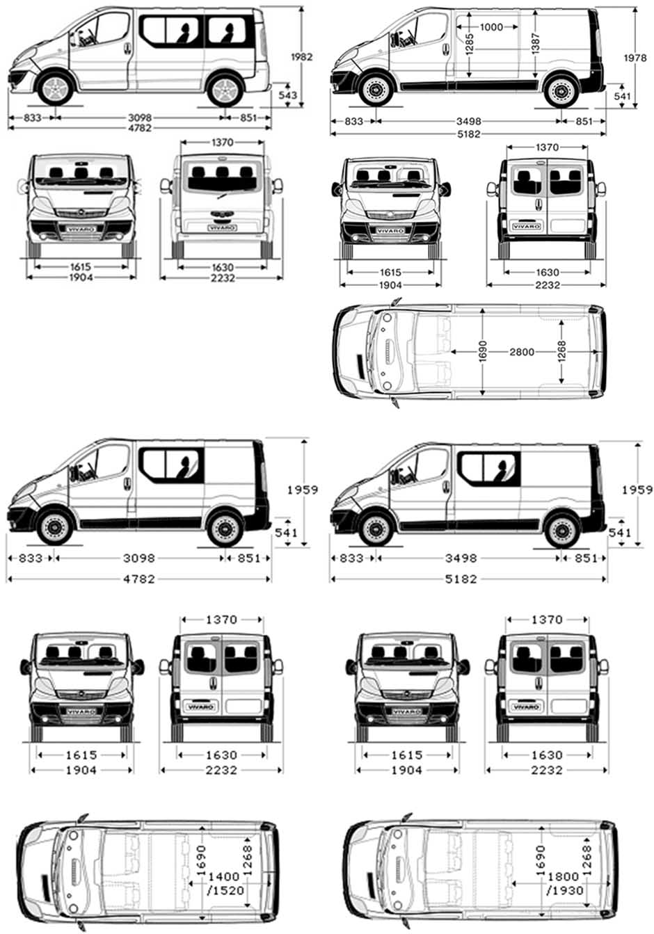
| № | Спецификация / Specs | Данные |
| Габариты (мм/mm) и масса (кг/kg) / Dimensions and Weight | ||
| 1 | Длина / Length | 5182 |
| 2 | Ширина (без/с зеркалами) / Width | 1904/2232 |
| 3 | Высота (загружен/пустой) / Height | 1959 |
| 4 | Колёсная база / Wheelbase | 3498 |
| 5 | Дорожный просвет (клиренс) / Ground clearance | 180 |
| 6 | Снаряжённая масса / Total (curb) weight | 1764 |
| Полная масса / Gross (max.) weight | 2935 | |
|
Двигатель / Engine |
||
| 7 | Тип / Engine Type, Code | Дизельный, жидкостного охлаждения, четырехтактный, M9R |
| 8 | Количество цилиндров / Cylinder arrangement: Total number of cylinders, of valves | 4-цилиндровый, 16V, рядный, DOHC с верхним расположением двух распределительных валов |
| 9 | Диаметр цилиндра / Bore | 84.0 мм |
| 10 | Ход поршня / Stroke | 84.0 мм |
| 11 | Объём / Engine displacement | 1995 см³ |
| 12 | Система питания / Fuel supply, Aspiration | Непосредственный впрыск топлива насос-форсунками ТНВД Common |
| Турбонаддув и охлаждение наддувочного воздуха | ||
| 13 | Степень сжатия / Compression ratio | 15.6:1 |
| 14 | Максимальная мощность / Max. output power kW (HP) at rpm | 84 кВт (115 л.с.) при 3500 об/мин |
| 15 | Максимальный крутящий момент / Max. torque N·m at rpm | 290 Нм при 1600 об/мин |
|
Трансмиссия / Transmission |
||
| 16 | Сцепление / Clutch type | Однодисковое, сухое, с диафрагменной нажимной пружиной и гасителем крутильных колебаний, постоянно замкнутого типа |
| 17 | КПП / Transmission type | МКПП 6 шестиступенчатая механическая, двухвальная, с синхронизаторами на всех передачах переднего хода |
О Книге
- Название: Renault Trafic Ⅱ, Nissan Primastar, Opel Vivaro Руководство по эксплуатации, техническое обслуживание, ремонт, особенности конструкции, электросхемы
- Дизельные двигатели F9Q 1,9 л dCi 8V SOHC 60 кВт (82 л.с.) F9Q 1,9 л dCi 8V SOHC 74 кВт (100 л.с.) M9R 2,0 л dCi 16V DOHC 66 кВт (90 л.с.) M9R 2,0 л dCi 16V DOHC 84 кВт (115 л.с.) G9U 2,5 л dCi 16V DOHC 99 кВт (135 л.с.) G9U 2,5 л dCi 16V DOHC 107 кВт (145 л.с.)
- Выпуск с 2001 года.
- Серия: «Производственно-практическое издание»
- Год издания: 2012
- Автор: Коллектив авторов
- Издательство: «Ассоциация независимых издателей»
- Формат: PDF
- Страниц в книге: 376
- Размер: 64.82 МБ
- Язык: Русский
- Количество электросхем: 24