Subaru Legacy 2.0R AWD ♘Black knight♘

mb5888
Был 13 часов назад
Саня Гайдодеев, 33 года
Я езжу на Subaru Legacy 2.0R AWD ♘Black knight♘ (до этого — 5 машин)
Мариуполь, Россия

Мануал «Устройство, техническое обслуживание и ремонт» владельцам Subaru Legacy, Outback, B4, Lancaster моделей с 1999 по 2006 год! Может кому и понадобится!
yadi.sk/i/SnykrL183QKFYj
4 декабря 2017
Метки: другое
7
Ранее Диагностика🔌 своими руками и мозгами
Далее Повторители поворотов в зеркала↩
Разместить рекламу
Реклама
Машины в продаже

Шахты
Subaru Legacy, 2004
840 000 ₽

Краснодар
Subaru Legacy, 2004
600 000 ₽

Ейск
Subaru Legacy, 2005
570 000 ₽

Краснодар
Subaru Legacy, 2005
600 000 ₽
Посмотреть больше машин на Дроме
Комментарии
7
Войдите или зарегистрируйтесь, чтобы писать комментарии, задавать вопросы и участвовать в обсуждении.
Войти
Зарегистрироваться

Shuum
Я езжу на Subaru Impreza WRX (GD, GG)
Спасибо!
2 месяца

ProWax
Я езжу на BMW X6 (E71/E72)
Вот еще море мануалов, от пользовательских до сервисных:
jdmfsm.info/Auto/Japan/Subaru/
5 лет

bairun
Я езжу на Subaru Legacy (BL/BP)
спс за инфу
5 лет

mb5888
Автор
Я езжу на Subaru Legacy (BL/BP)
Да не за что)
5 лет

somebody
Несуществующий пользователь
Без машины
Спасибо, давно хотел найти мануал)
5 лет
mb5888
Автор
Я езжу на Subaru Legacy (BL/BP)
На здоровье)
Лучше чтоб он не пригодился! Не ломайся!
5 лет
somebody
Несуществующий пользователь
Без машины
Будем стараться)
5 лет
Руководство на английском языке по техническому обслуживанию и ремонту автомобиля Subaru Legacy 2012 модельного года.
- Автор: —
- Издательство: Fuji Heavy Industries Ltd.
- Год издания: —
- Страниц: —
- Формат: PDF
- Размер: 138,2 Mb
Сборник руководств на английском языке по техническому обслуживанию и ремонту автомобиля Subaru Legacy второго поколения 1995-1999 годов выпуска.
- Автор: —
- Издательство: Fuji Heavy Industries Ltd.
- Год издания: —
- Страниц: —
- Формат: PDF
- Размер: 373,6 Mb
Сборник руководств на английском языке по техническому обслуживанию и ремонту автомобиля Subaru Legacy третьего поколения 2000-2003 годов выпуска.
- Автор: —
- Издательство: Fuji Heavy Industries Ltd.
- Год издания: —
- Страниц: —
- Формат: PDF
- Размер: 420,2 Mb
Сборник руководств на английском языке по техническому обслуживанию и ремонту автомобиля Subaru Legacy четвертого поколения 2003-2009 годов выпуска.
- Автор: —
- Издательство: Fuji Heavy Industries Ltd.
- Год издания: —
- Страниц: —
- Формат: PDF
- Размер: 219,0 Mb
Сборник руководств на английском языке по техническому обслуживанию и ремонту автомобиля Subaru Legacy 1989-1994 годов выпуска.
- Автор: —
- Издательство: Fuji Heavy Industries Ltd.
- Год издания: —
- Страниц: —
- Формат: PDF, HTML
- Размер: 70,5 Mb

Мультимедийное руководство по эксплуатации и ремонту автомобиля Subaru Legacy 1990-1998 годов выпуска.
- Автор: —
- Издательство: —
- Год издания: —
- Страниц: —
- Формат: —
- Размер: 211,4 Mb
Руководство по техническому обслуживанию и ремонту автомобиля Subaru Legacy 2008 года выпуска.
- Автор: —
- Издательство: Fuji Heavy Industries Ltd.
- Год издания: —
- Страниц: 5228
- Формат: PDF
- Размер: 80,1 Mb
Руководство по техническому обслуживанию и ремонту автомобиля Subaru Legacy 1990-1998 годов выпуска с бензиновыми двигателями объемом 1,8/2,0/2,2/2,5 л.
- Автор: —
- Издательство: Техно-ВООК
- Год издания: 1999
- Страниц: 272
- Формат: PDF
- Размер: 864,0 Mb

Руководство по эксплуатации, техническому обслуживанию и ремонту автомобилей Subaru Legacy/Legacy Outback 1989-1998 годов выпуска с бензиновыми двигателями.
- Автор: —
- Издательство: Легион-Автодата
- Год издания: —
- Страниц: 384
- Формат: —
- Размер: —

Руководство по эксплуатации, техническому обслуживанию и ремонту + каталог расходных запчастей автомобилей Subaru Legacy/Outback/Wagon/B4/Lancaster 1998-2003 годов выпуска с двигателями объемом 2,0/2,5/3,0 л.
- Автор: —
- Издательство: Легион-Автодата
- Год издания: —
- Страниц: 680
- Формат: —
- Размер: —

Руководство по эксплуатации, техническому обслуживанию и ремонту + каталог расходных запчастей автомобилей Subaru Legacy/Outback/Wagon/B4 2003-2009 годов выпуска с двигателями объемом 2,0/2,5/3,0 л.
- Автор: —
- Издательство: Легион-Автодата
- Год издания: —
- Страниц: 504
- Формат: —
- Размер: —

Руководство по эксплуатации и ремонту автомобилей Subaru Baja/Forester/Legacy/Outback с 2000 года выпуска с бензиновыми двигателями объемом 2,5 л.
- Автор: —
- Издательство: Монолит
- Год издания: —
- Страниц: 468
- Формат: —
- Размер: —

Руководство по эксплуатации и ремонту автомобилей Subaru Legacy и Subaru Outback с 2009 года выпуска с бензиновыми двигателями объемом 2,0/2,5/3,6 литра.
- Автор: —
- Издательство: Монолит
- Год издания: —
- Страниц: 728
- Формат: —
- Размер: —
Сборник руководств по эксплуатации и техническому обслуживанию автомобилей Subaru Legacy и Subaru Outback 2005-2007 годов выпуска.
- Автор: —
- Издательство: Fuji Heavy Industries Ltd.
- Год издания: 2004/2006
- Страниц: 600/528
- Формат: PDF
- Размер: 19,3 Mb
Руководство по эксплуатации и техническому обслуживанию автомобиля Subaru Legacy с 2003 года выпуска.
- Автор: —
- Издательство: MoToR
- Год издания: —
- Страниц: 600
- Формат: —
- Размер: —
Руководство по эксплуатации и ремонту автомобилей Subaru Forester с 1997 и Subaru Legacy/Outback 1999-2003 годов выпуска.
- Автор: —
- Издательство: —
- Год издания: —
- Страниц: —
- Формат: HTML
- Размер: 127,1 Mb

Мультимедийное руководство по эксплуатации и ремонту автомобилей Subaru Legacy и Subaru Outback 1999-2003 годов выпуска.
- Автор: —
- Издательство: —
- Год издания: —
- Страниц: —
- Формат: ISO
- Размер: 643,1 Mb

- Руководства по ремонту
- Руководство по ремонту Субару Легаси 1999-2003 г.в.
Руководство по ремонту Subaru Legacy Outback / Субару Легаси
Общая информация об автомобиле.

Рассматриваемые модели представлены в двух кузовных исполнениях Седан (Legacy) и Универсал (Legacy и Outback) и укомплектовываются 4-цилиндровым оппозитным двигателем двигателем 2.0 л (Legacy) или 2.5 л (Legacy и Outback), либо 6-цилиндровым, также оппозитным, двигателем 3.0 л (Outback).
На всех моделях применена распределенная система впрыска с электронным управлением (MFI).
Трансмиссия с постоянным полным приводом на все колеса (AWD) организована посредством 5-ступенчатой ручной коробки переключения передач (РКПП), 5-ступенчатой РКПП с дополнительным 2-ступенчатым редуктором (в сумме 10 ступеней), либо 4-ступенчатой автоматической трансмиссии (АТ), раздаточной коробки, межосевого дифференциала (на некоторых моделях LSD-типа), карданного вала, заднего дифференциала и четырех приводных валов.
Передняя подвеска полностью независимая, стоечного типа с телескопическими амортизаторами (Мак-Ферсон) и винтовыми пружинами, организована посредством поперечной балки, поперечных рычагов и стабилизатора поперечной устойчивости.
Задняя подвеска многорычажная, стоечного типа, с телескопическими амортизаторами и стабилизатором поперечной устойчивости.
На некоторых моделях в качестве дополнительной комплектации применяется пневматическая подвеска, в настоящем Руководстве не рассматриваемая.
Рулевой привод организован посредством реечной передачи и двух поперечных рулевых тяг. В стандартную комплектацию входит система гидроусиления руля.
Тормозные механизмы всех колес имеют дисковую конструкцию. Стояночный тормоз воздействует на задние колеса (барабанные сборки). В стандартную комплектацию всех моделей входят вакуумный усилитель тормозов и система антиблокировки (ABS).
↓ Комментарии ↓
1. Автомобили Subaru Legacy, Outback
1.0 Автомобили Subaru Legacy, Outback
1.2 Идентификационные номера и информационные ярлыки
1.3 Приобретение запасных частей
1.4 Технология обслуживания, инструмент и оборудование рабочего места
1.5 Поддомкрачивание и буксировка
1.6 Запуск двигателя от вспомогательного источника питания
1.7 Автомобильные химикалии, очистители, герметики
1.8 Диагностика неисправностей узлов и систем автомобиля
2. Руководство по эксплуатации
2.0 Руководство по эксплуатации
2.1. Доступ, защита
2.2. Элементы систем безопасности
2.3. Оборудование автомобиля, расположение приборов и органов управления
2.4. Комфорт
2.5. Приемы эксплуатации
3. Текущее обслуживание
3.0 Текущее обслуживание
3.1 График текущего обслуживания автомобилей Subaru Legacy и Outback
3.2 Спецификации
3.3 Общие сведения о настройках и регулировках
3.4 Проверка уровней жидкостей (в соответствии с Графиком текущего обслуживания)
3.5 Замена двигательного масла и масляного фильтра
3.6 Проверка состояния и замена расположенных в двигательном отсеке шлангов
3.7 Ротация колес
3.8 Смазывание компонентов шасси
3.9 Проверка состояния компонентов системы выпуска отработавших газов
3.10 Проверка состояния ремней безопасности
3.11 Проверка состояния компонентов подвески
3.12 Проверка состояния компонентов рулевого привода
3.13 Проверка и регулировка состава смеси холостого хода, — корме моделей, оборудованных каталитическим преобразователем
3.14 Проверка состояния защитных чехлов шарниров приводных валов
3.15 Проверка состояния, регулировка усилия натяжения ремней привода вспомогательных агрегатов
3.16 Проверка и регулировка противооткатного устройства
3.17 Проверка исправности функционирования и регулировка компонентов сцепления
3.18 Проверки и регулировки тормозной системы
3.19 Проверка состояния компонентов системы охлаждения
3.20 Проверка состояния и замена охлаждающей жидкости двигателя
3.21 Замена фильтрующего элемента воздухоочистителя
3.22 Проверка состояния компонентов системы питания
3.23 Замена тормозной жидкости/прокачка гидравлического тракта
3.24 Замена ATF автоматической трансмиссии
3.25 Замена трансмиссионного масла РКПП
3.26 Замена смазок заднего и переднего дифференциала
3.27 Проверка состояния и замена газораспределительного ремня — модели 2.0 и 2.5 л
3.28 Проверка и замена топливного фильтра
3.29 Проверка состояния и замена свечей зажигания и ВВ электропроводки
3.30 Проверка колесных подшипников
3.31 Проверка клапанных зазоров
3.32 Замена ремней привода вспомогательных агрегатов и замена
4. Двигатель
4.0 Двигатель
4.1 Спецификации
4.2 Проверка компрессионного давления в цилиндрах и герметичности блока
4.3 Диагностика состояния двигателя с применением вакуумметра
4.4 Система смазки двигателя — общая информация
4.5. Процедуры ремонта, не связанные с извлечением двигателя из автомобиля, — четырехцилиндровые двигатели
4.6. Процедуры ремонта, не связанные с извлечением двигателя из автомобиля, — шестицилиндровые двигатели
4.7. Общий и капитальный ремонт двигателей
5. Системы охлаждения, отопления
5.0 Системы охлаждения, отопления
5.1. Спецификации
5.2. Система охлаждения двигателя
5.3. Системы отопления/вентиляции/кондиционирования воздуха
6. Системы питания и выпуска
6.0 Системы питания и выпуска
6.1 Спецификации
6.2. Система впрыска топлива
6.3. Системы управления двигателем и снижения токсичности отработавших газов
6.4. Система выпуска отработавших газов
7. Электрооборудование двигателя
7.0 Электрооборудование двигателя
7.1 Спецификации
7.2 Запуск двигателя от вспомогательного источника питания
7.3 Снятие/установка, проверка и обслуживание аккумуляторной батареи
7.4 Проверка состояния и замена проводов батареи
7.5 Система зажигания — общая информация и меры предосторожности
7.6 Проверка исправности функционирования системы зажигания
7.7 Снятие, установка и проверка состояния модуля(ей) зажигания
7.8 Проверка и регулировка установки угла опережения зажигания
7.9 Замена датчиков CKP, CMP и KS
7.10 Обслуживание и замена свечей зажигания
7.11 Проверка состояния высоковольтных проводов (4-цилиндровые двигатели)
7.12 Система заряда — общая информация и меры предосторожности
7.13 Проверка состояния системы заряда
7.14 Генератор — общая информация, проверка и обслуживание
7.15 Снятие, разборка, сборка и установка генератора
7.16 Система запуска — общая информация и меры предосторожности
7.17 Проверка исправности функционирования стартера и цепи запуска
7.18 Стартер Nippondenso — проверка и обслуживание
7.19 Стартеры Mitsubishi — проверка и обслуживание
8. Ручная коробка и дифференциал
8.0 Ручная коробка и дифференциал
8.1 Спецификации
8.2 Механизм блокировки включения задней передачи — устройство и принцип функционирования
8.3 Межосевой дифференциал — устройство и принцип функционирования
8.4 Снятие и установка трансмиссионной сборки
8.5 Проверка состояния и замена элементов опор подвески трансмиссионной сборки
8.6 Проверка состояния и замена сальника
8.7 Снятие, установка и проверка состояния датчиков-выключателей
8.8 Снятие, установка и проверка состояния датчика скорости (VSS)
8.9 Подготовка к выполнению капитального ремонта РКПП
8.10 Снятие, обслуживание и установка раздаточной коробки и удлинения трансмиссии
8.11 Снятие, обслуживание и установка ведущей шестерни раздаточного механизма
8.12 Снятие, обслуживание и установка ведомой шестерни раздаточного механизма
8.13 Снятие, обслуживание и установка межосевого дифференциала
8.14 Снятие, обслуживание, установка и регулировка сборки механизма блокировки включения задней передачи
8.15 Снятие, установка и проверка состояния картера трансмиссионной сборки
8.16 Снятие, обслуживание, установка и регулировка первичного вала РКПП
8.17 Снятие, обслуживание и установка входного вала РКПП (модели с дополнительным двухступенчатым редуктором)
8.18 Снятие, обслуживание и установка сборки вала ведущей шестерни главной передачи привода передних колес
8.19 Снятие, обслуживание, установка и регулировка переднего дифференциала
8.20 Снятие, установка и проверка состояния шестерни привода спидометра
8.21 Снятие, установка и регулировка промежуточной шестерни задней передачи
8.22 Снятие, установка, проверка и регулировка сборки шестерен двухступенчатого редуктора
8.23 Снятие, проверка состояния и установка вилок и штоков переключения передач
8.24 Снятие, обслуживание и установка рычага переключения передач РКПП
8.25 Снятие, обслуживание и установка рычага переключения режимов «Hi/Lo» дополнительного двухступенчатого редуктора
8.26 Снятие, обслуживание и установка тросовой тяги привода переключения режимов двухступенчатого редуктора
9. Автоматическая трансмиссия
9.0 Автоматическая трансмиссия
9.1 Спецификации
9.2 Электрогидравлическая система управления — общая информация, назначение основных элементов
9.3 Система самодиагностики — общая информация и принципы функционирования
9.4 Диагностика общего состояния АТ
9.5 Диагностика отказов АТ
9.6 Снятие и установка трансмиссионной сборки
9.7 Замена элементов подвески трансмиссионной сборки
9.8 Замена сальника кожуха удлинения АТ
9.9 Проверка состояния, регулировка и замена датчика-выключателя разрешения запуска
9.10 Снятие и установка переднего датчика скорости (VSS)
9.11 Снятие и установка заднего датчика скорости (VSS)
9.12 Снятие и установка датчика оборотов турбины гидротрансформатора
9.13 Снятие, обслуживание и установка клапанной сборки
9.14 Замена электромагнитных клапанов переключения, исполнительных электромагнитных клапанов и датчика температуры ATF
9.15 Замена фильтра ATF
9.16 Снятие и установка модуля управления трансмиссии (TCM)
9.17 Снятие, установка и проверка состояния линий тракта охлаждения ATF
9.18 Снятие, обслуживание и установка компонентов рычага селектора АТ
9.19 Снятие, установка, проверка состояния и регулировка приводного троса селектора АТ
10. Сцепление
10.0 Сцепление
10.1 Спецификации
10.2. Маховик и сцепление
10.3. Приводные и карданный валы, задний дифференциал
11. Тормозная система
11.0 Тормозная система
11.1 Спецификации
11.2 Тормозные механизмы передних и задних колес — общая информация
11.3 Стояночный тормоз — конструкция и принцип функционирования
11.4 Клапан-ограничитель давления — конструкция и принцип функционирования
11.5 Противооткатная система — устройство, принцип функционирования и меры предосторожности
11.6 Система антиблокировки тормозов (ABS) — общая информация, принцип функционирования
11.7 Система динамической стабилизации (VDC) — общая информация, принцип функционирования
11.8 Проверка состояния замена колодок дисковых тормозных механизмов передних колес
11.9 Снятие, проверка состояния и установка передних тормозных дисков
11.10 Снятие, обслуживание и установка дисковых тормозных механизмов передних колес
11.11 Проверка состояния и замена колодок дисковых тормозных механизмов задних колес
11.12 Снятие, проверка состояния и установка задних тормозных дисков
11.13 Снятие, обслуживание и установка дисковых тормозных механизмов задних колес
11.14 Снятие, обслуживание и установка главного тормозного цилиндра (ГТЦ)
11.15 Снятие, установка и проверка исправности функционирования вакуумного усилителя тормозов
11.16 Снятие, установка и проверка исправности функционирования клапана-ограничителя давления
11.17 Замена тормозной жидкости
11.18 Прокачка гидравлического тракта тормозной системы
11.19 Проверка состояния и замена гибких тормозных шлангов
11.20 Проверка состояния и замена трубок тормозного тракта
11.21 Снятие, обслуживание, установка и регулировка педали ножного тормоза
11.22 Снятие, проверка состояния, установка и регулировка датчика-выключателя стоп-сигналов
11.23 Снятие, установка, проверка состояния и регулировка рычага привода стояночного тормоза
11.24 Снятие, проверка состояния и установка элементов тросового привода стояночного тормоза
11.25 Снятие, установка и регулировка механизма стояночного тормоза
11.26 Снятие, установка, проверка состояния и регулировка компонентов противооткатного устройства
11.27 Снятие, установка и проверка исправности функционирования сборки модуля управления/гидромодулятора ABS
11.28 Проверка последовательности срабатывания клапанов гидромодулятора ABS
11.29 Снятие, установка и проверка исправности функционирования передних колесных датчиков ABS
11.30 Снятие, установка и проверка исправности функционирования задних колесных датчиков ABS
11.31 Снятие, установка и проверка состояния роторов колесных датчиков
11.32 Снятие, установка и диагностика датчика перегрузок (G-датчик)
11.33 Диагностика отказов ABS
11.34 Снятие, установка и регулировка модуля управления VDC
11.35 Снятие, установка и проверка исправности функционирования гидромодулятора VDC
11.36 Проверка последовательности срабатывания клапанов гидромодуляторов ABS и VDC
11.37 Снятие, установка и проверка исправности функционирования датчика увода/поперечных перегрузок
11.38 Снятие, установка и проверка исправности функционирования датчика угла поворота рулевого колеса VDC
11.39 Снятие, установка и проверка исправности функционирования колесных датчиков с роторами
11.40 Снятие, установка и проверка исправности функционирования выключателя деактивации VDC (VDC OFF)
11.41 Диагностика отказов VDC
12. Подвеска и рулевое управление
12.0 Подвеска и рулевое управление
12.1 Спецификации
12.2. Передняя подвеска
12.3. Задняя подвеска
12.4. Рулевое управление
12.5. Колесные сборки, геометрия подвески
13. Кузов
13.0 Кузов
13.1 Спецификации
13.2 Обслуживание петель и замков автомобиля
13.3 Замена ветрового и прочих фиксированных стекол
13.4 Снятие и установка декоративной решетки радиатора
13.5 Снятие и установка панели защиты картера
13.6 Снятие и установка переднего бампера
13.7 Снятие и установка заднего бампера
13.8 Снятие и установка локеров защиты арок передних колес
13.9 Снятие и установка боковых накладок кузовных панелей
13.10 Снятие и установка переднего обтекателя
13.11 Снятие и установка заднего спойлера
13.12 Снятие и установка боковых спойлеров
13.13 Снятие и установка профильных направляющих верхнего багажника
13.14 Снятие установка главного вещевого ящика
13.15 Снятие и установка элементов центральной консоли
13.16 Снятие и установка панели приборов
13.17 Снятие и установка панелей внутренней обивки дверей, включая дверь задка (модели Legacy Универсал и Outback) и крышку багажного отделения (модели
13.18 Снятие и установка элементов внутренней отделки
13.19 Ремни безопасности — общая информация, проверка состояния, снятие и установка, порядок утилизации несработавших аварийных натяжителей
13.20 Снятие, обслуживание и установка сидений
13.21 Снятие, установка и регулировка капота
13.22 Снятие, установка и регулировка замка капота
13.23 Снятие и установка передних крыльев
13.24 Снятие, установка и регулировка дверных панелей
13.25 Снятие, обслуживание и установка компонентов верхних люков
13.26 Снятие, установка и проверка компонентов замковых сборок
13.27 Снятие, установка и регулировка дверных стекол и компонентов стеклоподъемников
13.28 Снятие, обслуживание и установка зеркал заднего вида
13.29 Снятие, обслуживание и установка стеклоочистителей и компонентов тракта подачи омывающей жидкости
13.30 Контрольные кузовные размеры
14. Бортовое электрооборудование
14.0 Бортовое электрооборудование
14.1 Спецификации
14.2 Поиск причин отказов электрооборудования
14.3 Предохранители — общая информация
14.4 Прерыватели цепи — общая информация
14.5 Реле — общая информация и проверка исправности функционирования
14.6 Детали прокладки бортовой электропроводки
14.7 Система дополнительной безопасности (SRS) — устройство и принцип функционирования
14.8 Диагностика неисправностей SRS
14.9 Снятие и установка компонентов SRS
14.10 Система управления скоростью (темпостат) — устройство и принцип функционирования
14.11 Проверка исправности функционирования компонентов и диагностика отказов темпостата
14.12 Снятие, проверка состояния и установка компонентов системы управления скоростью
14.13 Комбинация приборов — общая информация и принцип функционирования компонентов
14.14 Диагностика отказов компонентов комбинации приборов
14.15 Снятие, обслуживание и установка комбинации приборов, проверка состояния компонентов
14.16 Обогрев заднего стекла и зеркал заднего вида — общая информация, проверка исправности функционирования компонентов, восстановительный ремонт термоэлектрического нагревательного элемента
14.17 Обогрев щеток стеклоочистителей — общая информация, проверка исправности функционирования компонентов, восстановительный ремонт термоэлектрического нагревательного элемента
14.18 Снятие, проверка состояния и установка выключателей управления функционированием электропривода регуляторов стеклоподъемников
14.19 Электропривод зеркал заднего вида — проверка исправности функционирования
14.20 Снятие проверка и установка переключателя управления функционированием электропривода наружных зеркал заднего вида
14.21 Снятие, проверка состояния и установка переключателя управления функционированием электропривода верхнего люка
14.22 Снятие, проверка состояния и установка комбинированных подрулевых переключателей
14.23 Проверка исправности функционирования электромоторов привода стеклоочистителей, снятие, проверка и установка управляющего реле заднего стеклоочистителя на моделях Legacy Универсал/Outback
14.24 Проверка реле и выключателей осветительных и сигнальных приборов
14.25 Снятие и установка осветительных приборов, замена ламп
14.26 Снятие, проверка состояния и установка рожков и выключателя клаксона
14.27 Проверка состояния и замена контактной группы выключателя зажигания
14.28 Единый замок — устройство, принцип функционирования, диагностика неисправностей
14.29 Снятие, проверка состояния и установка компонентов единого замка
14.30 Система иммобилизации двигателя — устройство, принцип функционирования, диагностика неисправностей
14.31 Снятие и установка компонентов системы иммобилизации двигателя
14.32 Снятие и установка сборки радиоприемника
14.33 Снятие и установка громкоговорителей
14.34 Проверка состояния и восстановительный ремонт оконной антенны радиоприемника
14.35 Снятие, установка и проверка состояния антенного усилителя радиоприемника
14.36 Снятие и установка прикуривателя
14.37. Схемы электрических соединений
Subaru Legacy / Outback / B4 / Wagon / Lancaster 1998-2003 года выпуска: Устройство, техническое обслуживание и ремонт
Тема в разделе «Разное», создана пользователем Buzlyator, 21 сен 2015.
-
Subaru Legacy / Outback / B4 / Wagon / Lancaster 1998-2003 года выпуска: Устройство, техническое обслуживание и ремонт
![[IMG]](data:image/svg+xml,%3Csvg%20xmlns='http://www.w3.org/2000/svg'%20viewBox='0%200%200%200'%3E%3C/svg%3E)
Издательство: Легион-Автодата
Жанр: SubaruКачество: Хорошее
Страниц: 680
Формат: pdf, fb2, epubРуководство по ремонту Subaru Legacy / Outback / B4 / Wagon / Lancaster с левосторонним и правосторонним рулевым управлением 1998-2003 года выпуска с двигателями (SOHC и DOHC) рабочим объемом 2,0 л; 2,0 л (с турбонаддувом); 2,5 л и 3,0 л. Издание содержит руководство по эксплуатации, подробные сведения по техническому обслуживанию автомобиля, диагностике, ремонту и регулировке элементов систем двигателя (в т.ч. системы впрыска топлива, турбонаддува, запуска и зарядки), механической и автоматических (4-х и 5-ти ступенчатых) коробок переключения передач (МКПП и АКПП), раздаточных коробок, элементов тормозной системы (включая антиблокировочную систему тормозов (ABS) и систему курсовой устойчивости (VDC)), рулевого управления, подвески, кузовных элементов, систем кондиционирования и вентиляции (AC), системы пассивной безопасности (SRS). Приведены инструкции по диагностике 8 электронных систем: управления двигателем, АКПП, ABS, VDC, системы изменения усилия на рулевом колесе, AC, SRS, иммобилайзера.
Вложения:
![[IMG]](http://piratebooks.ru/attachments/subaru-legacy-outback-b4-wagon-lancaster-1998-2003-goda-vypuska.jpg)
Поделиться этой страницей

- Manuals
- Brands
- Subaru Manuals
- Automobile
- 2005 Legacy
- Service manual
-
Contents
-
Table of Contents
-
Bookmarks
Related Manuals for Subaru Legacy 2005
Summary of Contents for Subaru Legacy 2005
-
Page 1
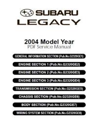
2005 Model Year PDF Service Manual GENERAL INFORMATION SECTION (Pub.No. G2360GE1) ENGINE SECTION 1 (Pub.No. G2360GE2) ENGINE SECTION 2 (Pub.No. G2360GE3) ENGINE SECTION 3 (Pub.No. G2360GE4) TRANSMISSION SECTION (Pub.No. G2360GE5) CHASSIS SECTION (Pub.No. G2360GE6) BODY SECTION (Pub.No. G2360GE7) WIRING SYSTEM SECTION (Pub.No. G2360GE8) -
Page 3
SECTION FOREWORD HOW TO USE THIS MANUALS SPECIFICATIONS PRECAUTION This service manual has been prepared to provide SUBARU service personnel NOTE with the necessary information and data for the correct maintenance and repair of SUBARU vehicles. IIDENTIFICATION This manual includes the procedures… -
Page 5
FOREWORD Page Foreword …………………2… -
Page 6
Foreword FOREWORD 1. Foreword A: FOREWORD These manuals are used when performing mainte- nance, repair, or diagnosis of Subaru LEGACY. Applied model: BL*****, BP***** from 2005MY The manuals contain the latest information at the time of publication. Changes in specifications, methods, etc. -
Page 7: How To Use This Manuals
HOW TO USE THIS MANUALS Page How to Use This Manuals …………….2…
-
Page 8
How to Use This Manuals HOW TO USE THIS MANUALS 1. How to Use This Manuals A: HOW TO USE THIS MANUALS 1. STRUCTURE Each section consists of SCT that are broken down into SC that are divided into sections for each com- ponent. -
Page 9
How to Use This Manuals HOW TO USE THIS MANUALS 3. COMPONENT Illustrations are provided for each component. The information necessary for repair work (tightening torque, grease up points, etc.) is described on these illustrations. Information is described using symbol. To order parts, refer to parts catalogue. -
Page 10
How to Use This Manuals HOW TO USE THIS MANUALS 4. SPECIFICATION If necessary, specifications are also included. 5. INSPECTION Inspections to be carried out before and after maintenance are included. 6. MAINTENANCE • Maintenance instructions for serviceable parts describe work area and detailed step with illustration. It also describes the use of special tool, tightening torque, caution for each procedure. -
Page 11
How to Use This Manuals HOW TO USE THIS MANUALS 7. DIAGNOSIS Tables showing a step-by-step process make it easy to conduct diagnosis. 8. SI UNITS Measurements in these manuals are according to the SI units. Metric and yard/pound measurements are also included. -
Page 12
: Exhaust Gas Recirculation SOHC : Single Overhead Camshaft : Emergency Locking Retractor : Supplemental Restraint System : Exhaust : Subaru Select Monitor : Fuse & Joint Box : Special Tool : Fusible Link : Switch : Full-time AWD : Traction Control System… -
Page 13: Specifications
SPECIFICATIONS Page LEGACY………………….2…
-
Page 14
LEGACY SPECIFICATIONS 1. LEGACY A: DIMENSION 1. SEDAN MODEL 2.0 L DOHC 3.0 L DOHC 3.0 L DOHC Model 2.0 L SOHC 2.5 L SOHC turbo Overall length mm (in) 4,665 (183.7) Overall width mm (in) 1,730 (68.1) Overall height (at C.W.) mm (in) 1,425 (56.1) 1,435 (56.5) -
Page 15
LEGACY SPECIFICATIONS B: ENGINE Model 2.0 L SOHC 2.0 L DOHC turbo 2.5 L SOHC 3.0 L DOHC Horizontally opposed, liquid Horizontally opposed, liquid cooled, 4-cylinder, 4-stroke gaso- Engine type cooled, 6-cylinder, line engine 4-stroke gasoline engine Valve arrangement Overhead camshaft 92 ×… -
Page 16
LEGACY SPECIFICATIONS D: TRANSMISSION Sedan, Wagon Model 2.0 L SOHC 2.0 L DOHC turbo 2.5 L SOHC Transmission type Clutch type DSPD DSPD DSPD 2.785 3.454 3.540 3.166 2.785 3.454 1.545 1.947 2.264 1.882 1.545 2.062 1.000 1.366 1.471 1.296 1.000 1.448 0.694… -
Page 17
LEGACY SPECIFICATIONS 5MT: 5-forward speeds with synchromesh and 1-reverse 6MT: 6-forward speeds with synchromesh and 1-reverse 4AT: Electronically controlled fully-automatic, 4-forward speeds and 1-reverse 5AT: Electronically controlled fully-automatic, 5-forward speeds and 1-reverse DSPD: Dry Single Plate Diaphragm TCC: Torque Converter Clutch ★1 : KA, KS model ★2… -
Page 18
LEGACY SPECIFICATIONS I: CAPACITY 2.0 L SOHC Model 2 (US gal, Imp Fuel tank 64 (16.9, 14.1) gal) Capacity (at 2 (US qt, Imp qt) 4.5 (4.8, 4.0) overhaul) When replacing Engine Filling amount of engine oil and oil 4.2 (4.4, 3.7) engine oil filter 2 (US qt, Imp… -
Page 19
LEGACY SPECIFICATIONS 2.5 L SOHC Model 2 (US gal, Imp Fuel tank 64 (16.9, 14.1) gal) Capacity (at 2 (US qt, Imp qt) 4.5 (4.8, 4.0) overhaul) When replacing Engine Filling amount of engine oil and oil 4.2 (4.4, 3.7) engine oil filter 2 (US qt, Imp… -
Page 20
LEGACY SPECIFICATIONS J: WEIGHT 1. SEDAN MODEL • LHD model ★1 Option code 2.0 L SOHC Model 2.0 i 5MT (Single range model) Front kg (lb) 740 (1,631) 755 (1,664) 760 (1,676) 765 (1,686) 755 (1,664) Curb weight Rear kg (lb) 590 (1,301) 590 (1,301) 590 (1,301) -
Page 21
LEGACY SPECIFICATIONS ★1 Option code 2.0 L SOHC Model 2.0 i Front kg (lb) 760 (1,676) 775 (1,709) 780 (1,720) 785 (1,731) 780 (1,720) Curb weight Rear kg (lb) 590 (1,301) 590 (1,301) 590 (1,301) 610 (1,345) 595 (1,312) (C.W.) Total kg (lb) 1,350 (2,976) 1,365 (3,009) 1,370 (3,020) 1,395 (3,076) 1,375 (3,032) Maximum… -
Page 22
LEGACY SPECIFICATIONS ★1 Option code 2.5 L SOHC Model 2.5 i 5MT (Single range model) Front kg (lb) 760 (1,676) 770 (1,698) 765 (1,686) 765 (1,686) 775 (1,709) Curb weight Rear kg (lb) 605 (1,334) 605 (1,334) 605 (1,334) 610 (1,345) 615 (1,356) (C.W.) Total… -
Page 23
LEGACY SPECIFICATIONS ★1 Option code 2.5 L SOHC Model 2.5 i 5MT (Single range model) Front kg (lb) 780 (1,720) 785 (1,731) 780 (1,720) 790 (1,742) 785 (1,731) 785 (1,731) Curb weight Rear kg (lb) 625 (1,378) 625 (1,378) 605 (1,334) 605 (1,334) 610 (1,345) 610 (1,345) -
Page 24
LEGACY SPECIFICATIONS ★1 Option code 2.5 L SOHC 3.0 L DOHC Model 2.5 i 3.0 R Front kg (lb) 790 (1,742) 800 (1,764) 805 (1,774) 880 (1,940) 890 (1,962) 890 (1,962) Curb weight Rear kg (lb) 610 (1,345) 615 (1,356) 625 (1,378) 625 (1,378) 635 (1,400) -
Page 25
LEGACY SPECIFICATIONS ★1 Option code 3.0 L DOHC Model 3.0 R spec. B Front kg (lb) 885 (1,951) 895 (1,973) 895 (1,973) 895 (1,973) Curb weight Rear kg (lb) 635 (1,400) 645 (1,422) 645 (1,422) 645 (1,422) (C.W.) Total kg (lb) 1,520 (3,352) 1,540 (3,396) 1,540 (3,396) 1,540 (3,396) Maximum Front kg (lb) 1,040 (2,293) 1,040 (2,293) 1,040 (2,293) 1,040 (2,293) -
Page 26
LEGACY SPECIFICATIONS ★1 Option code 2.0 L SOHC Model 2.0 i 5MT (Single range model) Front kg (lb) 750 (1,653) 750 (1,653) 760 (1,676) 770 (1,698) 770 (1,698) Curb weight Rear kg (lb) 590 (1,301) 590 (1,301) 600 (1,323) 590 (1,301) 590 (1,301) (C.W.) Total… -
Page 27
LEGACY SPECIFICATIONS ★1 Option code 2.0 L SOHC 2.5 L SOHC Model 2.0 i 2.5 i 5MT (Single range model) Front kg (lb) 775 (1,709) 770 (1,698) 780 (1,720) 760 (1,676) 770 (1,698) 770 (1,698) Curb weight Rear kg (lb) 590 (1,301) 590 (1,301) 595 (1,312) -
Page 28
LEGACY SPECIFICATIONS ★1 Option code 2.5 L SOHC Model 2.5 i Front kg (lb) 790 (1,742) 795 (1,753) 780 (1,720) 790 (1,742) 790 (1,742) 800 (1,764) Curb weight Rear kg (lb) 605 (1,334) 610 (1,345) 595 (1,312) 605 (1,334) 610 (1,345) 615 (1,356) (C.W.) Total… -
Page 29
LEGACY SPECIFICATIONS ★1 Option code 3.0 L DOHC Model 3.0 R 3.0 R spec. B Front kg (lb) 890 (1,962) 880 (1,940) 890 (1,962) 880 (1,940) 895(1,973) 890 (1,962) Curb weight Rear kg (lb) 635 (1,400) 635 (1,400) 635 (1,400) 625 (1,378) 645 (1,422) 645 (1,422) -
Page 30
LEGACY SPECIFICATIONS • RHD model ★1 Option code 2.0 L SOHC Model 2.0 i 5MT (Single range model) Front kg (lb) 760 (1,676) 760 (1,676) 770 (1,698) 780 (1,720) 780 (1,720) 790 (1,742) Curb weight Rear kg (lb) 590 (1,301) 595 (1,312) 605 (1,334) 590 (1,301) -
Page 31
LEGACY SPECIFICATIONS ★1 Option code 2.5 L SOHC Model 2.5 i 5MT (Single range model) Front kg (lb) 770 (1,698) 770 (1,698) 780 (1,720) 785 (1,731) 790 (1,742) 790 (1,742) Curb weight Rear kg (lb) 605 (1,334) 610 (1,345) 620 (1,367) 625 (1,378) 610 (1,345) 615 (1,356) -
Page 32
LEGACY SPECIFICATIONS ★1 Option code 2.5 L SOHC 3.0 L DOHC Model 2.5 i 3.0 R Front kg (lb) 810 (1,785) 810 (1,785) 880 (1,940) 890 (1,962) 890 (1,962) Curb weight Rear kg (lb) 620 (1,367) 620 (1,367) 625 (1,378) 635 (1,400) 635 (1,400) (C.W.) -
Page 33
LEGACY SPECIFICATIONS ★1 Option code 3.0 L DOHC Model 3.0 R spec. B Front kg (lb) 885 (1,951) 895 (1,973) 895 (1,973) 895 (1,973) Curb weight Rear kg (lb) 635 (1,400) 645 (1,422) 645 (1,422) 645 (1,422) (C.W.) Total kg (lb) 1,520 (3,352) 1,540 (3,396) 1,540 (3,396) 1,540 (3,396) Maximum Front kg (lb) 1,040 (2,293) 1,040 (2,293) 1,040 (2,293) 1,040 (2,293) -
Page 34
LEGACY SPECIFICATIONS ★1 Option code 2.0 L SOHC 2.0 L DOHC turbo Model 2.0 i 2.0 GT 5MT (Single range model) Front kg (lb) 760 (1,676) 780 (1,720) 820 (1,808) 835 (1,841) Curb weight Rear kg (lb) 590 (1,301) 590 (1,301) 615 (1,356) 635 (1,400) (C.W.) -
Page 35
LEGACY SPECIFICATIONS ★1 Option code 2.0 L DOHC turbo 2.5 L SOHC Model 2.0 GT 2.5 i 5MT (Single range model) Front kg (lb) 845 (1,863) 860 (1,896) 770 (1,698) 780 (1,720) Curb weight Rear kg (lb) 615 (1,356) 635 (1,400) 610 (1,345) 620 (1,367) (C.W.) -
Page 36
LEGACY SPECIFICATIONS ★1 Option code 2.5 L SOHC 3.0 L DOHC Model 2.5 i 3.0 R 3.0 R spec. B Front kg (lb) 790 (1,742) 800 (1,764) 805 (1,774) 890 (1,962) 890 (1,962) Curb weight Rear kg (lb) 610 (1,345) 625 (1,378) 625 (1,378) 635 (1,400) -
Page 37
LEGACY SPECIFICATIONS 2. WAGON MODEL • LHD model ★1 Option code 2.0 L SOHC Model 2.0 i 5MT (Dual range model) Front kg (lb) 750 (1,653) 765 (1,686) 770 (1,698) 770 (1,698) 780 (1,720) Curb weight Rear kg (lb) 610 (1,345) 610 (1,345) 610 (1,345) 615 (1,356) -
Page 38
LEGACY SPECIFICATIONS ★1 Option code 2.0 L SOHC Model 2.0 i Front kg (lb) 760 (1,676) 775 (1,709) 780 (1,720) 780 (1,720) 790 (1,742) Curb weight Rear kg (lb) 610 (1,345) 610 (1,345) 610 (1,345) 615 (1,356) 635 (1,400) (C.W.) Total kg (lb) 1,370 (3,020) 1,385 (3,053) 1,390 (3,064) 1,395 (3,076) 1,425 (3,142) Maximum… -
Page 39
LEGACY SPECIFICATIONS ★1 Option code 2.5 L SOHC Model 2.5 i 5MT (Dual range model) Front kg (lb) 770 (1,698) 780 (1,720) 780 (1,720) 775 (1,709) 785 (1,731) 785 (1,731) Curb weight Rear kg (lb) 625(1,378) 625 (1,378) 625 (1,378) 630 (1,389) 640 (1,411) 645 (1,422) -
Page 40
LEGACY SPECIFICATIONS ★1 Option code 2.5 L SOHC Model 2.5 i 5MT (Dual range model) Front kg (lb) 790 (1,742) 780 (1,720) 790 (1,742) 785 (1,731) 785 (1,731) 795 (1,753) Curb weight Rear kg (lb) 655 (1,444) 625 (1,378) 625 (1,378) 630 (1,389) 630 (1,389) 640 (1,411) -
Page 41
LEGACY SPECIFICATIONS ★1 Option code 2.5 L SOHC 3.0 L DOHC Model 2.5 i 3.0 R Front kg (lb) 790 (1,742) 800 (1,764) 805 (1,775) 880 (1,940) 890 (1,962) 890 (1,962) Curb weight Rear kg (lb) 630 (1,389) 645 (1,422) 655 (1,444) 645 (1,422) 665 (1,466) -
Page 42
LEGACY SPECIFICATIONS ★1 Option code 3.0 L DOHC 2.0 L SOHC Model 3.0 R spec. B 2.0 i 5MT (Dual range model) Front kg (lb) 885 (1,951) 895 (1,973) 895 (1,973) 760 (1,676) 760 (1,676) Curb weight Rear kg (lb) 655 (1,444) 675 (1,488) 675 (1,488) -
Page 43
LEGACY SPECIFICATIONS ★1 Option code 2.0 L SOHC 2.5 L SOHC Model 2.0 i 2.5 i 5MT (Dual range model) Front kg (lb) 770 (1,698) 770 (1,698) 775 (1,698) 770 (1,698) 780 (1,720) 790 (1,742) Curb weight Rear kg (lb) 610 (1,345) 610 (1,345) 610 (1,345) -
Page 44
LEGACY SPECIFICATIONS ★1 Option code 2.5 L SOHC Model 2.5 i Front kg (lb) 790 (1,742) 800 (1,764) 795 (1,753) 800 (1,764) Curb weight Rear kg (lb) 645 (1,422) 650 (1,433) 645 (1,422) 650 (1,433) (C.W.) Total kg (lb) 1,435 (3,164) 1,450 (3,196) 1,440 (3,175) 1,450 (3,196) Maximum Front kg (lb) 1,040 (2,293) 1,040 (2,293) 1,040 (2,293) 1,040 (2,293) -
Page 45
LEGACY SPECIFICATIONS ★1 Option code 3.0 L DOHC Model 3.0 R 3.0 R spec. B Front kg (lb) 890 (1,962) 890 (1,962) 880 (1,940) 890 (1,962) 895 (1,973) Curb weight Rear kg (lb) 665 (1,466) 665 (1,466) 665 (1,466) 675 (1,488) 675 (1,488) (C.W.) Total… -
Page 46
LEGACY SPECIFICATIONS ★1 Option code 2.0 L SOHC 2.0 L DOHC turbo Model 2.0 i 2.0 GT 5MT (Dual range model) Front kg (lb) 770 (1,698) 780 (1,720) 820 (1,808) 835 (1,841) Curb weight Rear kg (lb) 610 (1,345) 610 (1,345) 635 (1,400) 665 (1,466) (C.W.) -
Page 47
LEGACY SPECIFICATIONS ★1 Option code 2.0 L DOHC turbo 2.5 L SOHC Model 2.0 GT 2.5 i 5MT (Dual range model) Front kg (lb) 845 (1,863) 860 (1,896) 780 (1,720) 795 (1,753) Curb weight Rear kg (lb) 635 (1,400) 665 (1,466) 630 (1,389) 650 (1,433) (C.W.) -
Page 48
LEGACY SPECIFICATIONS ★1 Option code 2.5 L SOHC 3.0 L DOHC Model 2.5 i 3.0 R 3.0 R spec. B Front kg (lb) 790 (1,742) 800 (1,764) 805 (1,775) 885 (1,951) 890 (1,962) Curb weight Rear kg (lb) 630 (1,389) 650 (1,433) 650 (1,433) 665 (1,466) -
Page 49
LEGACY SPECIFICATIONS 3. OUTBACK • LHD model ★1 Option code 2.5 L SOHC Model OUTBACK 2.5 i 5MT (Dual range model) Front kg (lb) 785 (1,731) 785 (1,731) 795 (1,753) 785 (1,731) 800 (1,764) 795 (1,753) Curb weight Rear kg (lb) 650 (1,433) 655 (1,444) 670 (1,477) -
Page 50
LEGACY SPECIFICATIONS ★1 Option code 2.5 L SOHC Model OUTBACK 2.5 i Front kg (lb) 795 (1,753) 805 (1,775) 800 (1,764) 810 (1,785) 815 (1,797) 815 (1,797) Curb weight Rear kg (lb) 655 (1,444) 670 (1,470) 655 (1,444) 675 (1,488) 670 (1,477) 675 (1,488) (C.W.) -
Page 51
LEGACY SPECIFICATIONS ★1 Option code 3.0 L DOHC 2.5 L SOHC Model OUTBACK 3.0 R OUTBACK 2.5 i 5MT (Dual range model) Front kg (lb) 890 (1,962) 900 (1,984) 900 (1,984) 785 (1,731) 795 (1,753) 785 (1,731) Curb weight Rear kg (lb) 670 (1,477) 685 (1,510) -
Page 52
LEGACY SPECIFICATIONS ★1 Option code 2.5 L SOHC Model OUTBACK 2.5 i 5MT (Dual range model) Front kg (lb) 795 (1,753) 795 (1,753) 795 (1,753) 805 (1,774) 810 (1,785) 795 (1,753) Curb weight Rear kg (lb) 655 (1,444) 660 (1,455) 645 (1,422) 670 (1,477) 670 (1,477) -
Page 53
LEGACY SPECIFICATIONS ★1 Option code 2.5 L SOHC 3.0 L DOHC Model OUTBACK 2.5 i OUTBACK 3.0 R Front kg (lb) 805 (1,774) 805 (1,774) 900 (1,984) 890 (1,962) 900 (1,984) 900 (1,984) Curb weight Rear kg (lb) 655 (1,444) 660 (1,455) 685 (1,510) 685 (1,510) -
Page 54
LEGACY SPECIFICATIONS • RHD model ★1 Option code 2.5 L SOHC Model OUTBACK 2.5 i 5MT (Dual range model) Front kg (lb) 800 (1,764) 790 (1,742) 790 (1,742) 810 (1,785) 800 (1,764) 820 (1,801) Curb weight Rear kg (lb) 675 (1,488) 645 (1,422) 655 (1,444) 670 (1,477) -
Page 55
LEGACY SPECIFICATIONS ★1 Option code 2.5 L SOHC 3.0 L DOHC Model OUTBACK OUTBACK 3.0 R 2.5 i Front kg (lb) 800 (1,764) 895 (1,973) 905 (1,995) 905 (1,995) Curb weight Rear kg (lb) 655 (1,444) 670 (1,477) 685 (1,510) 685 (1,510) (C.W.) Total… -
Page 56
LEGACY SPECIFICATIONS ★1 Option code 2.5 L SOHC Model OUTBACK 2.5 i 5MT (Dual range model) Front kg (lb) 790 (1,742) 800 (1,764) 800 (1,764) 800 (1,764) 810 (1,785) Curb weight Rear kg (lb) 645 (1,422) 665 (1,466) 670 (1,477) 645 (1,422) 665 (1,466) (C.W.) -
Page 57
LEGACY SPECIFICATIONS ★1 Option code 2.5 L SOHC 3.0 L DOHC Model OUTBACK OUTBACK 3.0 R 2.5 i Front kg (lb) 810 (1,785) 885 (1,951) 900 (1,984) Curb weight Rear kg (lb) 670 (1,477) 660 (1,455) 685 (1,510) (C.W.) Total kg (lb) 1,480 (3,263) 1,545 (3,407) 1,585 (3,494) Front kg (lb) 1,040 (2,293) 1,040 (2,293) 1,040 (2,293) -
Page 58
LEGACY SPECIFICATIONS SPC-46… -
Page 59
PRECAUTION Page Precaution ………………..2… -
Page 60
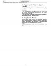
Precaution PRECAUTION 1. Precaution 6. AIRBAG To prevent bodily injury from unexpected deploy- A: CAUTION ment of airbags and unnecessary maintenance, fol- The following precautions must be understood and low the instructions in this manual when performing strictly adhered to avoid minor or serious injury to maintenance on the airbag components or nearby, the person doing the work or people in the area, around front of the vehicle (radiator panel, front… -
Page 61
Precaution PRECAUTION 12.OIL When handing oil, adhere to the following to pre- vent from unexpected accident. • Prepare a container and cloth when performing work which oil possibly spills. If oil spills, wipe it off immediately to prevent from penetrating into floor or flowing out for environmental protection. -
Page 62
Precaution PRECAUTION PC-4… -
Page 63
NOTE Page Note………………….2… -
Page 64
4. SERVICE PARTS not reach the supporting locations. Use genuine parts for maximum performance and maintenance when conducting repairs. Subaru/FHI will not be responsible for poor performance result- ing from the use of parts except for genuine parts. 5. PROTECTING VEHICLE UNDER MAIN-… -
Page 65
Note NOTE NT-00086 Supporting locations Swing arm lift Plate lift Pantograph jack Rigid rack Attachment NT-3… -
Page 66
Note NOTE NT-00072 Front Rear Front crossmember Rear differential 8. TIE DOWNS Tie downs are used when transporting vehicles and when using the chassis dynamo. Attach tie-down only to the specified locations on the vehicle. • TIE-DOWN LOCATION NT-00073 Hook for tie-down NT-4… -
Page 67
Note NOTE • CHAIN DIRECTION AT TIE-DOWN CONDI- • VEHICLE SINKING VOLUME AT TIE-DOWN TION CONDITION Measure the distance between the highest tire NOTE: point and highest arch point before and after tie- Pull the chains LH and RH in the same direction, down. -
Page 68
Note NOTE 9. TOWING Avoid towing vehicles except when the vehicle cannot be driven. For models with AWD, AT or VTD, use a loader instead of towing. When towing other vehicles, pay attention to the following to prevent hook or vehicle damage resulting from excessive weight. -
Page 69
Note NOTE • NOTES Towing Notes ❍ ❍ Lifting up four wheels (On a trailer) Towing the vehicle after lifting up all four wheels is a basic rule for AWD model. NT-00023 ❍ ▲ Rope • Check if both front and rear wheels are rotated nor- mally. -
Page 70
Note NOTE CAUTION: • Check ATF, gear oil and rear differential oil before driving. • Place the shift lever in “N” position during towing. • Do not lift up the rear wheels to avoid unsteady rotation. • Turn the ignition key to “ACC”, then check the steering wheel moves freely. •… -
Page 71
Fix the vehicle using a pulling metal (chain or Subaru Select Monitor can be used to diagnose the wire) to the front and rear towing hooks or tie- engine, ABS, AT and other parts. -
Page 72
Note NOTE 14.BRAKE TEST (2) When the brake dragging force is large. • Check the dragging of brake pad or brake 1) Full-time AWD MT model shoe. (1) Perform this test after driving the vehicle 2 to 3 km (1.24 to 1.86 miles) on road in order to sta- Specifications: bilize the viscous torque of viscous coupling. -
Page 73
IDENTIFICATION Page Identification ………………..2… -
Page 74
Identification IDENTIFICATION 1. Identification A: IDENTIFICATION 1. IDENTIFICATION NUMBER AND LABEL LOCATIONS The V.I.N. (Vehicle Identification Numbers) is used to classify the vehicle. • Positioning of the plate label for identification ID-00072 ID plate (EC, EK, EH and ER Tire inflation pressure label Saudi Arabia plate (Saudi Arabia model) (Driver’s side) (KA model) -
Page 75
Identification IDENTIFICATION • Engine • Rear differential T-type ID-00059 ID-00056 (1) Engine serial number (Punch mark) (1) Type (white paint) (2) Engine type (Crankcase upper side) VA1-type • Automatic transmission DI-00396 ID-00067 (1) Type (label) (1) AT type label (2) Transmission serial number label VA2-type •… -
Page 76
Identification IDENTIFICATION • Model number plate ID-00111 2. MEANING OF V.I.N. The meaning of the V.I.N. is as follows: • EC, EK, KA AND K4 model ]JF1BL5LJ35G002001[ The starting and ending brackets ( ] [ ) are stop marks. Digits Code Meaning Details… -
Page 77
Identification IDENTIFICATION • KS model ]JF1BL54MX5G002001[ The starting and ending brackets ( ] [ ) are stop marks. Digits Code Meaning Details 1 — 3 Manufacturer body area JF1: Passenger car, FHI made Car line LEGACY Body type L: Sedan P: Wagon Displacement 5: 2.0 L AWD… -
Page 78
Identification IDENTIFICATION The engine and transmission type are as follows: • Engine EJ202NTBHA Digits Code Meaning Details 1 and 2 Engine type EJ: 4 cylinders EZ: 6 cylinders 3 and 4 Displacement 20: 2.0 L 25: 2.5 L 30: 3.0 L Fuel feed system 2: D-MPI-NA (SOHC) 3: MPI-NA (SOHC) -
Page 79
Identification IDENTIFICATION • Rear differential Code Reduction gear ratio 4.111 None 4.111 None 3.700 None 3.900 Viscous 3.272 Viscous 4.444 Viscous 3.083 Viscous 4.111 Viscous 3.545 Viscous • Option ECXV Digits Code Meaning Details 1 — 2 Destination EC: for Europe (LHD model) EK: for Europe (RHD model) KS: For GCC countries K4: For Middle and South America… -
Page 80
Identification IDENTIFICATION Digits Code Meaning Details Option equipment A: A/C B: A/C, Side airbag, Self levelizer C: A/C, Side airbag, Curtain airbag F: A/C, Side airbag, Sunroof J: A/C, Sunroof K: A/C, Side airbag, Curtain airbag, Sunroof, Navigation system L: A/C, Side airbag, Curtain airbag, Self levelizer N: A/C, Side airbag, Curtain airbag, Navigation system, Self levelizer, Sunroof O: A/C, Side airbag, Navigation system, Curtain airbag… -
Page 81
RECOMMENDED MATERIALS Page Recommended Materials …………….2… -
Page 82
Recommended Materials RECOMMENDED MATERIALS 1. Recommended Materials A: RECOMMENDED MATERIALS 1. GENERAL To insure the best performance, always use the specified oil, gasoline, adhesive, sealant, etc. or a substitute of equivalent quality. 2. FUEL Always use gasoline of the same or higher octane value than specified in the owner’s manual. -
Page 83
Recommended Materials RECOMMENDED MATERIALS 3. LUBRICANTS Use either the lubricants in the table below or equivalent lubricants. See the table below to choose the correct SAE viscosity. Recommended Alternative Lubricant API Standard or ILSAC Standard ACEA standard API standard Engine oil SL, SJ Grade “Energy conserving”… -
Page 84
Recommended Materials RECOMMENDED MATERIALS SAE viscosity No. and applicable temperature Engine oil SOHC model (˚C) –30 –20 –10 (˚F) –22 –4 10W-30 or 10W-40 5W-30 0W-20 Recommend RM-00007 3.0 L and DOHC turbo model –20 –10 (˚C) –30 –22 –4 (˚F) 10W-30 or 10W-40 5W-30 Recommend… -
Page 85
Distilled water — Tap water (Soft water) 6. REFRIGERANT Standard air conditioners on Subaru vehicles use HFC134a refrigerant. Do not mix it with other refrigerants. Also, do not use any compressor oil other than DENSO OIL 8. Air conditioner Recommended… -
Page 86
Recommended Materials RECOMMENDED MATERIALS 7. GREASE Use the grease and supplementary lubricants shown in the table below. Grease Application point Recommended Item number Alternative Supplementary • Oxygen sensor Spray type lubricant — — lubricants • Bolts, etc. Grease MT main shaft NICHIMOLY N-130 —… -
Page 87
Recommended Materials RECOMMENDED MATERIALS 9. SEAL MATERIAL Use the seal material shown in the table below, or equivalent. Seal material Application point Recommended Item number Alternative Seal material • MT transmission case • Cylinder block • Converter case THREE BOND 1215 004403007 DOW CORNING’s No. -
Page 88
Recommended Materials RECOMMENDED MATERIALS RM-8… -
Page 89
PRE-DELIVERY INSPECTION Page Pre-delivery Inspection…………….2… -
Page 90
• Check if the vehicle after repair is in a normal state. • Make sure to provide a complete vehicle to the customer. For the above reasons, all SUBARU dealers (dealerships) carry out the PDIs before delivering a vehicle. Refer to this manual unless otherwise specified. -
Page 91
Pre-delivery Inspection PRE-DELIVERY INSPECTION PROCEDURE Check point 15. Engine oil Check that the oil level is normal. 16. Transmission gear oil Check that the transmission gear oil level is normal. 17. AT front differential oil Check that the AT front differential oil level is normal. 18. -
Page 92
Pre-delivery Inspection PRE-DELIVERY INSPECTION CHECKS AFTER DYNAMIC TEST PROCEDURE Check point 50. ATF level Check that the ATF level is correct. 51. Power steering fluid level Check that the power steering fluid level is normal. 52. Fluid leak check Check for fluid/oil leaks. 53. -
Page 93
Pre-delivery Inspection PRE-DELIVERY INSPECTION 2) Completely close the driver’s door, and then 6. CHECK DOUBLE LOCK OPERATION check the smooth movement with operating door 1) Fully open all the windows. lock knob from lock to unlock several times. Set the 2) Remove the key. -
Page 94
Pre-delivery Inspection PRE-DELIVERY INSPECTION 8. CHECK TRUNK LID FOR OPEN/CLOSE 10.OPERATION CHECK OF FUEL LID OPERATIONS OPENER LOCK RELEASE LEVER 1) Operate the trunk lock release lever to check Operate the fuel lid opener and verify that the fuel that the trunk opens normally. filler flap lid is unlocked normally. -
Page 95
Pre-delivery Inspection PRE-DELIVERY INSPECTION 12.OPERATION CHECK OF FRONT HOOD 13.BATTERY LOCK RELEASE SYSTEM Check the battery terminals to make sure that there are no rust or corrosions due to fluid leaks. Check Operate the front hood lock release lever (A) to that the battery caps are securely tightened. -
Page 96
Pre-delivery Inspection PRE-DELIVERY INSPECTION 15.ENGINE OIL 16.TRANSMISSION GEAR OIL Check the engine oil amount. If the amount of oil is Check that the transmission gear oil level is normal. insufficient, check that no leaks are found. Then, If the amount of fluid is insufficient, check that no add the necessary amount of the specified engine leaks are found. -
Page 97
The following inspections show the initial settings. (A) Oil level gauge When the settings are different from the initial set- tings, use Subaru Select Monitor to check the de- (B) Upper level tails of each setting for inspections. <Ref. to (C) Lower level LAN(diag)-26, OPERATION, Read Current Data.>… -
Page 98
Pre-delivery Inspection PRE-DELIVERY INSPECTION 3) Press the trunk open button (except for EK mod- 6) Press the “UNLOCK” button momentarily on the el) or “UNLOCK” button (EK model) for more than keyless transmitter. Check that all the doors are un- one second. -
Page 99
Pre-delivery Inspection PRE-DELIVERY INSPECTION 26.TEST MODE CONNECTOR 28.STARTING CONDITION Turn the ignition switch to ON and check that the Start the engine and check that the engine starts malfunction indicator light starts blinking. If the light smoothly. If the battery voltage is low, recharge or blinks, return the ignition key to LOCK. -
Page 100
Pre-delivery Inspection PRE-DELIVERY INSPECTION 39.WINDOW WASHER 45.PARKING BRAKE Check that the window washer system injects Check the parking brake for normal operations. washer fluid to the specified area of the windshield When applying the parking brake with force of 200 shown in the figure. -
Page 101
Pre-delivery Inspection PRE-DELIVERY INSPECTION 50.ATF LEVEL 51.POWER STEERING FLUID LEVEL Set the selector lever “P” range after selecting all Check that the power steering fluid level is normal. positions (P, R, N, D). Measure the ATF level after If the amount is insufficient, check that no leaks are the engine idles for 1 to 2 minutes. -
Page 102
Pre-delivery Inspection PRE-DELIVERY INSPECTION 54.APPEARANCE CHECK 2 6) Peel the protective tape, vinyl wrapping and identification seal attached to the following places. 1) When vehicle body is covered with protective • Seat film, peel it off. • Door trim NOTE: •… -
Page 103: Table Of Contents
PERIODIC MAINTENANCE SERVICES Page General Description ………………2 Schedule …………………3 Engine Oil………………..7 Engine Oil Filter……………….9 Spark Plug………………..10 V-belt………………….11 Timing Belt ………………..14 Fuel Line ………………..17 Air Cleaner Element ………………18 Cooling System ………………20 Engine Coolant………………22 Clutch System ……………….25 Transmission Gear Oil …………….26 Automatic Transmission Fluid …………..27 Front &…
-
Page 104: General Description
General Description PERIODIC MAINTENANCE SERVICES 1. General Description A: GENERAL DESCRIPTION Be sure to perform periodic maintenance in order to maintain vehicle performance and find problems before they occur. PM-2…
-
Page 105: Schedule
Schedule PERIODIC MAINTENANCE SERVICES 2. Schedule A: MAINTENANCE SCHEDULE 1 1. EUROPE AREA For periodic maintenance of less than 120,000 km (75,000 miles) or 96 months, carry out inspection by re- ferring to the following table. For a maintenance period gone beyond these tables, apply them repeatedly as a set of 120,000 km (75,000 miles) or 96 months.
-
Page 106
Schedule PERIODIC MAINTENANCE SERVICES 2. EXCEPT FOR EUROPE AREA For periodic maintenance of less than 50,000 km (30,000 miles) or 48 months, carry out inspections by re- ferring to the following tables. For a maintenance period gone beyond these tables, apply them repeatedly as a set of 50,000 km (30,000 miles) or 48 months. -
Page 107
Schedule PERIODIC MAINTENANCE SERVICES NOTE: (1) Periodic inspection and replacement of the timing chains on the 3.0 L models is not required. (2) When the vehicle is used in extremely dusty conditions, the air cleaner element should be replaced more often. (3) ATF filter is maintenance free part. -
Page 108
Schedule PERIODIC MAINTENANCE SERVICES 2. EXCEPT FOR EUROPE AREA Salt or other Repeat Extremely High humid- Repeat short corrosive Repeat tow- Item Every rough/muddy cold weather ity or moun- distance drive used or ing trailer road drive area tain area coastal area Engine oil Replace… -
Page 109: Engine Oil
Engine Oil PERIODIC MAINTENANCE SERVICES 3. Engine Oil • 2.0 L non-turbo and 2.5 L model A: REPLACEMENT CAUTION: If the engine oil gets on the under cover, wipe it off with cloth. 1) Open the engine oil filter cap for quick draining of engine oil.
-
Page 110
API (A) Oil level gauge standard and SAE viscosity No. designated by (B) Oil filler cap SUBARU. (C) Upper level (D) Lower level NOTE: If the vehicle is used in areas with very high temper-… -
Page 111: Engine Oil Filter
Engine Oil Filter PERIODIC MAINTENANCE SERVICES 4. Engine Oil Filter 5) Tighten more (approx. 1 turn for oil filter 68 mm (2.68 in) in outer diameter, approx. 2/3 — 3/4 turn A: REPLACEMENT for oil filter 65 mm (2.56 in) in outer diameter, ap- prox.
-
Page 112: Spark Plug
Spark Plug PERIODIC MAINTENANCE SERVICES 5. Spark Plug • 3.0 L model A: REPLACEMENT 1. SOHC MODEL 1) Remove the intake duct and intake chamber. 2) Remove the battery. 3) Disconnect the spark plug cord. 4) Remove the spark plug with a spark plug socket. IG-02004 (A) Bracket (B) Connector…
-
Page 113: V-Belt
V-belt PERIODIC MAINTENANCE SERVICES 6. V-belt Belt tension (with belt tension gauge): A: INSPECTION When installing new one: 640 — 785 N (65.3 1. EXCEPT FOR 3.0 L MODEL — 80.0 kgf, 144 — 176 lbf) At inspection: 490 — 640 N (50 — 65 kgf, 110 1) Replace the belts if crack, fraying or wear is —…
-
Page 114
V-belt PERIODIC MAINTENANCE SERVICES 2. 3.0 L MODEL • Turbo model 1) Replace the belts if crack, fraying or wear is found. 2) Check that the V-belt automatic tensioner indica- tor (A) is within the range (D). ME-00807 3) Loosen the lock bolt (A). 4) Loosen the slider bolt (B). -
Page 115
V-belt PERIODIC MAINTENANCE SERVICES Tightening torque: ⋅ 23 N m (2.3 kgf-m, 17.0 ft-lb) PM-00005 7) Install the front side belt. • Non-turbo model <Ref. to ME(H4SO 2.0)-37, FRONT SIDE BELT, INSTALLATION, V-belt.> • Turbo model <Ref. to ME(H4DOTC)-40, FRONT SIDE BELT, INSTALLATION, V-belt.>… -
Page 116: Timing Belt
Timing Belt PERIODIC MAINTENANCE SERVICES 7. Timing Belt ST 499987500 CRANKSHAFT SOCKET A: REPLACEMENT 1. SOHC MODEL 1) Protect the radiator with cardboard and blanket. 2) Remove the V-belt covers. PM-00003 3) Remove the V-belts. <Ref. to ME(H4SO 2.0)-37, V-belt.> 4) Remove the A/C compressor V-belt tensioner.
-
Page 117
Timing Belt PERIODIC MAINTENANCE SERVICES 2. DOHC MODEL 9) Remove the timing belt guide. (With timing belt guide model) 1) Protect the radiator with cardboard and blanket. 2) Remove the V-belts. <Ref. to ME(H4DOTC)-40, V-belt.> 3) Remove the A/C compressor V-belt tensioner. 4) Remove the pulley bolt. -
Page 118
Timing Belt PERIODIC MAINTENANCE SERVICES ST 499987500 CRANKSHAFT SOCKET CAUTION: When installing the timing belt, be sure to align all alignment marks on the belt with corre- sponding marks on the sprockets. If incorrectly installed, interference between pistons and valves may occur. B: INSPECTION 1. -
Page 119: Fuel Line
Fuel Line PERIODIC MAINTENANCE SERVICES 8. Fuel Line A: INSPECTION The fuel line is located mostly internally, so check pipes, areas near pipes, and engine compartment piping for rust, hose damage, loose band, etc. If faulty parts are found, repair or replace them. •…
-
Page 120: Air Cleaner Element
Air Cleaner Element PERIODIC MAINTENANCE SERVICES 9. Air Cleaner Element • Non-turbo model A: REPLACEMENT 1) Disconnect the ground cable from battery. PM-00182 • Turbo model IN-00203 2) Disconnect the connector from mass air flow sensor. (2.0 L turbo, 3.0 L and 2.5 L EC, EK, K4, EH, ER model) •…
-
Page 121
Air Cleaner Element PERIODIC MAINTENANCE SERVICES • Refer to “COMPONENT” for tightening torque. 2.0 L non-turbo and 2.5 L model <Ref. to IN(H4SO 2.0)-2, COMPONENT, Gen- eral Description.> Turbo model <Ref. to IN(H4DOTC)-2, COMPONENT, Gener- al Description.> 3.0 L model <Ref. -
Page 122: Cooling System
Cooling System PERIODIC MAINTENANCE SERVICES 10.Cooling System NOTE: Rust or dirt on the cap may prevent valve from func- A: INSPECTION tioning normally: be sure to clean the cap before 1) To check the radiator for leakage, fill it with en- testing.
-
Page 123
CO(H6DO)-14, Thermostat.> <Ref. to CO(H6DO)- 16, Radiator.> <Ref. to CO(H6DO)-19, Radiator Cap.> 4) Check the radiator fan operates using Subaru Select Monitor, when the coolant temperature ex- ceeds 95°C (203°F). If it does not operate, check the radiator fan system. -
Page 124: Engine Coolant
Materials.> The SUBARU Genuine Coolant containing anti- freeze and anti-rust agents is especially made for SUBARU engine, which has an aluminum crank- case. Always use SUBARU Genuine Coolant, since other coolant may cause corrosion. 10) Close the radiator (for turbo model, coolant fill- er tank) cap to start the engine and race 5 to 6 times at less than 3,000 rpm, then stop the engine.
-
Page 125
Concentration and safe operating temperature of (for turbo model, coolant filler tank). SUBARU coolant is shown in the diagram. Measur- 12) Perform the procedures 9) and 10) again. ing the temperature and specific gravity of the cool- 13) Attach the radiator (for turbo model, coolant fill- ant will provide this information. -
Page 126
2 (2.2 US qt, 1.8 Imp qt) of coolant from the cool- ing system and add 2.1 2 (2.2 US qt, 1.8 Imp qt) of the undiluted solution of SUBARU coolant. If a coolant concentration of 50% is needed, drain all the coolant and refill with the undiluted solution only. -
Page 127: Clutch System
Clutch System PERIODIC MAINTENANCE SERVICES 12.Clutch System • Be careful not to allow dirt or dust to get into the reservoir tank. A: INSPECTION AND ADJUSTMENT 1) Push the release lever to retract the push rod of the operating cylinder and check if the fluid level in the clutch reservoir tank rises or not.
-
Page 128: Transmission Gear Oil
Transmission Gear Oil PERIODIC MAINTENANCE SERVICES 13.Transmission Gear Oil NOTE: Each oil manufacturer has its base oil and addi- A: REPLACEMENT tives. Thus, do not mix two or more brands. 1. MANUAL TRANSMISSION Gear oil capacity: 1) Drain the gear oil by removing drain plug. 3.5 2 (3.7 US qt, 3.1 Imp qt) NOTE: •…
-
Page 129: Automatic Transmission Fluid
5 to 10 km (3 to 6 miles). Otherwise, idle the en- gine to raise ATF temperature to 70 — 80°C (158 PI-00190 — 176°F) on Subaru Select Monitor. <Ref. to (A) Level gauge 4AT(diag)-16, READ CURRENT DATA, OPERA- TION, Subaru Select Monitor.>…
-
Page 130
Automatic Transmission Fluid PERIODIC MAINTENANCE SERVICES B: REPLACEMENT 4) Check the ATF level. <Ref. to PM-27, INSPEC- TION, Automatic Transmission Fluid.> 1. AUTOMATIC TRANSMISSION FLUID • 4AT model 1) Drain the ATF by removing drain plug. NOTE: • Before starting work, cool off the ATF well. •… -
Page 131: Front & Rear Differential Gear Oil
Front & Rear Differential Gear Oil PERIODIC MAINTENANCE SERVICES 15.Front & Rear Differential Gear Recommended gear oil: Refer to “RM” section. <Ref. to RM-3, LUBRI- CANTS, RECOMMENDED MATERIALS, Rec- ommended Materials.> A: REPLACEMENT NOTE: 1. FRONT DIFFERENTIAL (MT MODEL) Each oil manufacturer has its base oil and addi- tives.
-
Page 132
Front & Rear Differential Gear Oil PERIODIC MAINTENANCE SERVICES Liquid gasket: • Use a new aluminum gasket for VA-type. THREE BOND 1105 (Part No. 004403010) Liquid gasket: Tightening torque: THREE BOND 1105 (Part No. 004403010) T-type Tightening torque: ⋅ 49 N m (5.0 kgf-m, 36.2 ft-lb) T-type VA1-type… -
Page 133: Brake Line
Brake Line PERIODIC MAINTENANCE SERVICES 16.Brake Line 2. SERVICE BRAKE 1) Check the free play of brake pedal with pulling A: INSPECTION up the force of less than 10 N (1 kgf, 2 lbf). 1. BRAKE LINE Brake pedal free play (Pulling up direction of pedal) 1) Check for scratches, swelling, corrosion, traces of fluid leakage on the brake hoses or pipe joints.
-
Page 134
Brake Line PERIODIC MAINTENANCE SERVICES 3) Check the pedal stroke. Replace the both check valve and vacuum hose if the check valve is faulty. Engine side of vacuum While the engine is idling, depress the brake pedal with a 490 N (50 kgf, 110 lbf) load and measure the hose is indicated by marking “ENG”… -
Page 135: Brake Fluid
Brake Fluid PERIODIC MAINTENANCE SERVICES 17.Brake Fluid 5) Install one end of a vinyl tube onto the air bleeder and insert the other end of the tube into a container A: REPLACEMENT to collect the brake fluid. CAUTION: Be careful not to let the brake fluid get on the vehicle body.
-
Page 136
Brake Fluid PERIODIC MAINTENANCE SERVICES 12) Install the wheels, and drive the vehicle for a short distance between 2 to 3 km (1 to 2 miles) to confirm brakes are operating properly. PM-34… -
Page 137: Disc Brake Pad And Disc
Disc Brake Pad and Disc PERIODIC MAINTENANCE SERVICES 18.Disc Brake Pad and Disc A: INSPECTION 1) Jack-up the vehicle and support with rigid racks. Then remove the wheels. 2) Visually check the pad thickness through inspec- tion hole of disc brake assembly. Replace the pad if necessary.
-
Page 138: Parking Brake
Parking Brake PERIODIC MAINTENANCE SERVICES 19.Parking Brake 4) When the shoe return spring tension is exces- sively weakened, replace it. A: INSPECTION B: ADJUSTMENT Inspect the brake linings and disc rotor of both For rear disc brake, adjust the parking brake after sides of the rear brake at the same time by remov- bleeding air.
-
Page 139: Suspension
Suspension PERIODIC MAINTENANCE SERVICES 20.Suspension NOTE: When the front arm ball joint has been removed or A: INSPECTION replaced, check the toe-in of front wheel. If the front wheel toe-in is not at specification, adjust the toe- 1. SUSPENSION BALL JOINT in.
-
Page 140
Suspension PERIODIC MAINTENANCE SERVICES 4. WHEEL ALIGNMENT OF FRONT SUS- 8. DAMAGE TO SUSPENSION PARTS PENSION Check the following parts and the fastening portion of the vehicle body for deformation or excessive 1) Check the alignment of front suspension to en- rusting which impairs the suspension. -
Page 141: Wheel Bearing
Wheel Bearing PERIODIC MAINTENANCE SERVICES 21.Wheel Bearing 6) While supporting rear drive shaft horizontally with one hand, turn the hub with the other hand to A: INSPECTION check for noise or binding. If the hub is noisy or binds, replace the rear axle. 1.
-
Page 142: Axle Boots & Joints
Axle Boots & Joints PERIODIC MAINTENANCE SERVICES 22.Axle Boots & Joints A: INSPECTION 1. FRONT AND REAR AXLE BOOTS Inspect the front axle boots (A) and rear axle boots (B) for deformation, damage or failure. If faulty, re- place them with new ones. <Ref. to DS-22, Front Drive Shaft.>…
-
Page 143: Steering System (Power Steering)
Steering System (Power Steering) PERIODIC MAINTENANCE SERVICES 23.Steering System (Power 2. STEERING SHAFT JOINT Steering) When the steering wheel free play is excessive, disconnect the universal joint of steering shaft and A: INSPECTION check it for any play and yawing torque (at the point of the crossing direction).
-
Page 144
Steering System (Power Steering) PERIODIC MAINTENANCE SERVICES 3) With the vehicle placed on a level surface, quick- 3) Check the lock nut on the tie-rod for tightness. If ly turn the steering wheel to the left and right. it is loose, retighten it to the specified torque. While steering wheel is being rotated, check the Tightening torque: gear backlash. -
Page 145
Steering System (Power Steering) PERIODIC MAINTENANCE SERVICES 7. HOSES OF OIL PUMP FOR DAMAGES Check the pressure hose and return hose of oil pump for crack, swell or damage. Replace the hose with a new one if necessary. NOTE: Prevent hoses from turning and/or bending when installing hoses. -
Page 146: A/C Filter
A/C Filter PERIODIC MAINTENANCE SERVICES 24.A/C Filter A: REPLACEMENT 1) Remove the instrument panel side cover. PM-00273 2) Remove the clips and damper. PM-00274 (1) Clip (2) Damper 3) Remove the tray. PM-00275 4) Remove the A/C filter. PM-00276 5) Install in the reverse order of removal. PM-44…
-
Page 147
(AUX. EMISSION CONTROL DEVICES) INTAKE (INDUCTION) IN(H4SO 2.0) MECHANICAL ME(H4SO 2.0) This service manual has been prepared to provide SUBARU service personnel EXHAUST EX(H4SO 2.0) with the necessary information and data for the correct maintenance and repair of SUBARU vehicles. -
Page 149
2005 LEGACY SERVICE MANUAL QUICK REFERENCE INDEX ENGINE SECTION 1 LUBRICATION LU(H4SO 2.5) SPEED CONTROL SYSTEMS SP(H4SO 2.5) IGNITION IG(H4SO 2.5) STARTING/CHARGING SYSTEMS SC(H4SO 2.5) EN(H4SO 2.5) ENGINE (DIAGNOSTICS) (diag) G2360GE2… -
Page 151
FUEL INJECTION (FUEL SYSTEM) FU(H4SO 2.0) Page General Description ………………2 Throttle Body…………………10 Intake Manifold………………11 Engine Coolant Temperature Sensor…………20 Crankshaft Position Sensor……………21 Camshaft Position Sensor……………..22 Knock Sensor………………..23 Throttle Position Sensor…………….25 Manifold Absolute Pressure Sensor…………26 Intake Air Temperature Sensor …………..27 EGR Valve ………………..28 Fuel Injector ………………..29 Front Oxygen (A/F) Sensor ……………32 Rear Oxygen Sensor……………..33… -
Page 152: General Description
General Description FUEL INJECTION (FUEL SYSTEM) 1. General Description A: SPECIFICATION 64 2 (16.9 US gal, 14.1 Imp gal) Capacity Fuel tank Location Under rear seat Type Impeller Shutoff discharge pressure 441 — 686 kPa (4.50 — 7.00 kgf/cm , 64.0 — 99.5 psi) Fuel pump 75 2 (19.8 US gal, 16.5 Imp gal)/h or more Discharge rate…
-
Page 153
General Description FUEL INJECTION (FUEL SYSTEM) B: COMPONENT 1. INTAKE MANIFOLD (17) (19) (11) (10) (17) (14) (12) (12) (10) (13) (12) (16) (18) (16) (18) (15) (16) (18) FU-02056 FU(H4SO 2.0)-3… -
Page 154
General Description FUEL INJECTION (FUEL SYSTEM) ⋅ Intake manifold (10) O-ring Tightening torque: N m (kgf-m, ft-lb) Gasket (11) Purge control solenoid valve T1: 1.25 (0.13, 0.94) Guide pin (12) Plug cord holder T2: 6.4 (0.65, 4.7) EGR valve (EC, EK, K4, ER (13) Nipple (LHD model) T3: 17 (1.7, 12.5) -
Page 155
General Description FUEL INJECTION (FUEL SYSTEM) 3. CRANKSHAFT POSITION, CAMSHAFT POSITION AND KNOCK SENSORS FU-00414 ⋅ Crankshaft position sensor Camshaft position sensor Tightening torque: N m (kgf-m, ft-lb) Knock sensor Camshaft position sensor support T1: 6.4 (0.65, 4.7) T2: 24 (2.4, 17.7) FU(H4SO 2.0)-5… -
Page 156
General Description FUEL INJECTION (FUEL SYSTEM) 4. FUEL TANK (19) (17) (18) (15) (16) (17) (14) (15) (10) (12) (11) (13) (22) (22) (20) (21) (23) (24) (25) FU-01080 FU(H4SO 2.0)-6… -
Page 157
General Description FUEL INJECTION (FUEL SYSTEM) Fuel tank (12) Fuel sub level sensor upper plate (23) Heat shield cover Fuel tank band RH (13) Fuel sub level sensor gasket (24) Fuel tank protector RH (Front) Fuel tank band LH (14) Fuel filler hose (25) Fuel tank protector LH (Front) -
Page 158
General Description FUEL INJECTION (FUEL SYSTEM) 5. FUEL LINE (28) (18) (26) (23) (15) (17) (19) (25) (27) (20) (22) (14) (13) (24) (21) (16) (22) (34) (11) (29) (10) (12) (35) (35) (35) (35) (33) (35) (32) (35) (30) (31) FU-02591 FU(H4SO 2.0)-8… -
Page 159
REMARKS 18482AA000 CARTRIDGE Troubleshooting for electrical system. (Newly adopted tool) ST18482AA000 22771AA030 SUBARU SELECT Troubleshooting for electrical system. MONITOR KIT • English: 22771AA030 (Without printer) • German: 22771AA070 (Without printer) • French: 22771AA080 (Without printer) • Spanish: 22771AA090 (Without printer) ST22771AA030 FU(H4SO 2.0)-9… -
Page 160: Throttle Body
Throttle Body FUEL INJECTION (FUEL SYSTEM) 2. Throttle Body A: REMOVAL 1) Disconnect the ground cable from battery. IN-00203 2) Remove the air intake chamber. <Ref. to IN(H4SO 2.0)-7, REMOVAL, Air Intake Chamber.> 3) Disconnect the connectors from the throttle posi- tion sensor and manifold absolute pressure sensor.
-
Page 161: Intake Manifold
Intake Manifold FUEL INJECTION (FUEL SYSTEM) 3. Intake Manifold 9) Disconnect the engine harness connectors from bulkhead harness connectors. A: REMOVAL 1) Release the fuel pressure. <Ref. to FU(H4SO 2.0)-38, RELEASING OF FUEL PRESSURE, PROCEDURE, Fuel.> 2) Open fuel filler flap lid, and remove fuel filler cap. 3) Disconnect the ground cable from battery.
-
Page 162
Intake Manifold FUEL INJECTION (FUEL SYSTEM) 14) Disconnect the connector from oil pressure • Catch the fuel from hoses using a container switch (B). or cloth. FU-01087 FU-02062 15) Disconnect the connector from camshaft posi- (A) Fuel delivery hose tion sensor. (B) Return hose (C) Evaporation hose 18) Remove the bolts which secure intake manifold… -
Page 163
Intake Manifold FUEL INJECTION (FUEL SYSTEM) Tightening torque: 6) Connect the connector to oil pressure switch (B). ⋅ 1.25 N m (0.13 kgf-m, 0.94 ft-lb) FU-01087 7) Connect the connector to crankshaft position FU-02062 sensor. (A) Fuel delivery hose (B) Return hose (C) Evaporation hose 3) Install the EGR pipe to intake manifold. -
Page 164
Intake Manifold FUEL INJECTION (FUEL SYSTEM) 11) Connect the brake booster hose. C: DISASSEMBLY 1) Disconnect the engine ground terminal from in- take manifold. FU-02089 12) Connect the engine harness connectors to bulkhead harness connectors. FU-02063 2) Remove the ignition coil and ignitor assembly. <Ref. -
Page 165
Intake Manifold FUEL INJECTION (FUEL SYSTEM) 7) Remove the fuel pipe protector RH. 12) Remove the bolts which install injector pipe on the intake manifold as shown in the figure. • RH Side FU-02066 Disconnect the connector from fuel injector. FU-02070 FU-02067 FU-02071… -
Page 166
Intake Manifold FUEL INJECTION (FUEL SYSTEM) 13) Remove the fuel injectors. 17) Remove the bolt which installs fuel pipes on in- take manifold. (1) Remove the clip which secures fuel injector from injector pipe. FU-02077 FU-02074 18) Remove the fuel pipe assembly and pressure regulator from intake manifold. -
Page 167
Intake Manifold FUEL INJECTION (FUEL SYSTEM) 3) Connect the fuel injector pipe RH to fuel hose, 7) Tighten the bolts which install injector pipe on in- and tighten the clamp. take manifold. • RH Side Tightening torque: ⋅ 1.25 N m (0.13 kgf-m, 0.94 ft-lb) Tightening torque: ⋅… -
Page 168
Intake Manifold FUEL INJECTION (FUEL SYSTEM) Tightening torque: 11) Connect the connectors to fuel injector. ⋅ 6.4 N m (0.65 kgf-m, 4.7 ft-lb) FU-02067 FU-02073 12) Install the fuel pipe protector RH. Install the engine harness to intake manifold. Tightening torque: 9) Hold the engine harness by harness band (A) ⋅… -
Page 169
Intake Manifold FUEL INJECTION (FUEL SYSTEM) 15) Install the EGR valve. (EC, EK, K4, ER model) <Ref. to FU(H4SO 2.0)-28, INSTALLATION, EGR Valve.> 16) Install the throttle body to intake manifold. <Ref. to FU(H4SO 2.0)-10, INSTALLATION, Throt- tle Body.> 17) Install the ignition coil and ignitor assembly. <Ref. -
Page 170: Engine Coolant Temperature Sensor
Engine Coolant Temperature Sensor FUEL INJECTION (FUEL SYSTEM) 4. Engine Coolant Temperature Sensor A: REMOVAL 1) Disconnect the ground cable from battery. IN-00203 2) Remove the generator. <Ref. to SC(H4SO 2.0)- 14, REMOVAL, Generator.> 3) Disconnect the connectors from engine coolant temperature sensor.
-
Page 171: Crankshaft Position Sensor
Crankshaft Position Sensor FUEL INJECTION (FUEL SYSTEM) 5. Crankshaft Position Sensor B: INSTALLATION Install in the reverse order of removal. A: REMOVAL Tightening torque: 1) Disconnect the ground cable from battery. ⋅ T: 6.4 N m (0.65 kgf-m, 4.7 ft-lb) IN-00203 FU-00058 2) Remove the bolt which installs crankshaft posi-…
-
Page 172: Camshaft Position Sensor
Camshaft Position Sensor FUEL INJECTION (FUEL SYSTEM) 6. Camshaft Position Sensor 6) Remove the camshaft position sensor itself. A: REMOVAL 1) Disconnect the ground cable from battery. FU-00179 B: INSTALLATION Install in the reverse order of removal. IN-00203 Tightening torque: 2) Disconnect the connector from camshaft posi- Camshaft position sensor support tion sensor.
-
Page 173: Knock Sensor
Knock Sensor FUEL INJECTION (FUEL SYSTEM) 7. Knock Sensor B: INSTALLATION 1) Install the knock sensor to cylinder block. A: REMOVAL NOTE: 1) Disconnect the ground cable from battery. Extraction area of knock sensor cord must be posi- tioned at a 60° angle relative to the engine rear. Tightening torque: ⋅…
-
Page 174
Knock Sensor FUEL INJECTION (FUEL SYSTEM) 5) Connect the ground cable to battery. IN-00203 FU(H4SO 2.0)-24… -
Page 175: Throttle Position Sensor
Throttle Position Sensor FUEL INJECTION (FUEL SYSTEM) 8. Throttle Position Sensor A: SPECIFICATION Throttle body is a non-disassembled part, so do not remove the throttle position sensor from throttle body. Refer to “Throttle Body” for removal and installation procedure. <Ref. to FU(H4SO 2.0)-10, REMOVAL, Throttle Body.>…
-
Page 176: Manifold Absolute Pressure Sensor
Manifold Absolute Pressure Sensor FUEL INJECTION (FUEL SYSTEM) 9. Manifold Absolute Pressure Sensor A: REMOVAL 1) Disconnect the ground cable from battery. IN-00203 2) Disconnect the connector from manifold abso- lute pressure sensor. FU-02079 3) Remove the manifold absolute pressure sensor from throttle body.
-
Page 177: Intake Air Temperature Sensor
Intake Air Temperature Sensor FUEL INJECTION (FUEL SYSTEM) 10.Intake Air Temperature Sen- A: REMOVAL 1) Disconnect the ground cable from battery. IN-00203 2) Disconnect the connector from intake air tem- perature sensor. 3) Remove the intake air temperature sensor. FU-02080 B: INSTALLATION Install in the reverse order of removal.
-
Page 178: Egr Valve
EGR Valve FUEL INJECTION (FUEL SYSTEM) 11.EGR Valve A: REMOVAL NOTE: EGR valve is equipped to EC, EK, K4 and ER mod- 1) Disconnect the ground cable from battery. IN-00203 2) Disconnect the connector from EGR valve. 3) Remove the EGR valve from intake manifold. FU-02082 B: INSTALLATION Install in the reverse order of removal.
-
Page 179: Fuel Injector
Fuel Injector FUEL INJECTION (FUEL SYSTEM) 12.Fuel Injector
Remove the clip which secure fuel injector. A: REMOVAL 1. RH SIDE 1) Release the fuel pressure. <Ref. to FU(H4SO 2.0)-38, RELEASING OF FUEL PRESSURE, PROCEDURE, Fuel.> 2) Open fuel filler flap lid, and remove fuel filler cap. 3) Disconnect the ground cable from battery. -
Page 180
Fuel Injector FUEL INJECTION (FUEL SYSTEM) 5) Remove the fuel pipe protector LH. Remove the bolts which hold fuel injector pipe to intake manifold. FU-02065 FU-02072 6) Disconnect the connector from fuel injector. FU-02073 FU-02067 9) Remove the fuel injector while lifting up the fuel 7) Remove the clip which secure fuel injector. -
Page 181
Fuel Injector FUEL INJECTION (FUEL SYSTEM) Tightening torque: Tightening torque: ⋅ ⋅ 6.4 N m (0.65 kgf-m, 4.7 ft-lb) 19 N m (1.9 kgf-m, 14 ft-lb) FU-02071 FU-02072 Tightening torque: Tightening torque: ⋅ ⋅ 19 N m (1.9 kgf-m, 14 ft-lb) 19 N m (1.9 kgf-m, 14 ft-lb) FU-02066… -
Page 182: Front Oxygen (A/F) Sensor
Front Oxygen (A/F) Sensor FUEL INJECTION (FUEL SYSTEM) 13.Front Oxygen (A/F) Sensor B: INSTALLATION 1) Before installing front oxygen (A/F) sensor, ap- A: REMOVAL ply anti-seize compound only to the threaded por- 1) Disconnect the ground cable from battery. tion of front oxygen (A/F) sensor to make the next removal easier.
-
Page 183: Rear Oxygen Sensor
Rear Oxygen Sensor FUEL INJECTION (FUEL SYSTEM) 14.Rear Oxygen Sensor B: INSTALLATION 1) Before installing the rear oxygen sensor, apply A: REMOVAL anti-seize compound only to the threaded portion of 1) Disconnect the ground cable from battery. the rear oxygen sensor to make the next removal easier.
-
Page 184: Engine Control Module (Ecm)
Engine Control Module (ECM) FUEL INJECTION (FUEL SYSTEM) 15.Engine Control Module (ECM) B: INSTALLATION Install in the reverse order of removal. A: REMOVAL CAUTION: 1) Disconnect the ground cable from battery. • When replacing the ECM, be careful not to use the wrong spec.
-
Page 185: Main Relay
Main Relay FUEL INJECTION (FUEL SYSTEM) 16.Main Relay A: REMOVAL 1) Disconnect the ground cable from battery. IN-00203 2) Remove the glove box. <Ref. to EI-51, REMOV- AL, Glove Box.> 3) Remove the harness cover (A). FU-02092 4) Disconnect the connector from main relay. FU-02093 B: INSTALLATION Install in the reverse order of removal.
-
Page 186: Fuel Pump Relay
Fuel Pump Relay FUEL INJECTION (FUEL SYSTEM) 17.Fuel Pump Relay A: REMOVAL 1) Disconnect the ground cable from battery. IN-00203 2) Remove the glove box. <Ref. to EI-51, REMOV- AL, Glove Box.> 3) Remove the harness cover (A). FU-02092 4) Disconnect the connector from fuel pump relay. FU-02094 B: INSTALLATION Install in the reverse order of removal.
-
Page 187: Electronic Throttle Control Relay
Electronic Throttle Control Relay FUEL INJECTION (FUEL SYSTEM) 18.Electronic Throttle Control Relay A: REMOVAL 1) Disconnect the ground cable from battery. IN-00203 2) Remove the glove box. <Ref. to EI-51, REMOV- AL, Glove Box.> 3) Remove the harness cover (A). FU-02092 4) Disconnect the connector from electronic throttle control relay.
-
Page 188: Fuel
Fuel FUEL INJECTION (FUEL SYSTEM) 19.Fuel 6) Set a container under the vehicle and remove the drain plug from fuel tank to drain fuel from the A: PROCEDURE fuel tank. 1. RELEASING OF FUEL PRESSURE WARNING: • Place “NO FIRE” signs near the working area. •…
-
Page 189: Fuel Tank
Fuel Tank FUEL INJECTION (FUEL SYSTEM) 20.Fuel Tank 7) Remove the service hole cover of fuel sub level sensor. A: REMOVAL (1) Remove the bolts (A). (2) Push the grommet (B) down and remove WARNING: service hole cover. • Place “NO FIRE” signs near the working area. •…
-
Page 190
Fuel Tank FUEL INJECTION (FUEL SYSTEM) 13) Remove the rear brake caliper and tie it to the 19) Remove the bolts which install the parking vehicle body side. brake cable clamp. FU-00462 FU-01130 14) Remove the parking brake cable from parking brake assembly. -
Page 191
Fuel Tank FUEL INJECTION (FUEL SYSTEM) (3) Remove the bolts which secure the rear CAUTION: suspension assembly to body. A helper is required to perform this work. FU-01133 FU-01137 B: INSTALLATION 1) Support the fuel tank with transmission jack, set the fuel tank, and then temporarily tighten the bolts of fuel tank band. -
Page 192
Fuel Tank FUEL INJECTION (FUEL SYSTEM) 2) Correctly insert the fuel filler hose (A) and vent Tightening torque: ⋅ hose (B) to specified position, and then tighten the T1: 125 N m (12.7 kgf-m, 92.2 ft-lb) ⋅ clamp. T2: 65 N m (6.6 kgf-m, 48 ft-lb) ⋅… -
Page 193
Fuel Tank FUEL INJECTION (FUEL SYSTEM) 6) Tighten the bolts which install the parking brake Tightening torque: ⋅ cable clamp. 33 N m (3.4 kgf-m, 24.3 ft-lb) Tightening torque: ⋅ 18 N m (1.8 kgf-m, 13 ft-lb) FU-01128 15) Install the rear wheels. 16) Lower the vehicle. -
Page 194
Fuel Tank FUEL INJECTION (FUEL SYSTEM) 20) Connect the connector to fuel pump. FU-01125 21) Install the service hole cover of fuel pump. FU-01124 (A) Bolt (B) Grommet 22) Install the rear seat. 23) Install the fuse of fuel pump to main fuse box. C: INSPECTION 1) Check that the fuel tank is not holed, cracked or otherwise damaged. -
Page 195: Fuel Filler Pipe
Fuel Filler Pipe FUEL INJECTION (FUEL SYSTEM) 21.Fuel Filler Pipe 6) Set a container under the vehicle and remove the drain plug from fuel tank to drain fuel from the A: REMOVAL fuel tank. WARNING: • Place “NO FIRE” signs near the working area. •…
-
Page 196
Fuel Filler Pipe FUEL INJECTION (FUEL SYSTEM) B: INSTALLATION 5) Tighten the bolts which hold the fuel filler pipe bracket on the body. 1) Open the fuel filler flap lid. 2) Set the fuel saucer (A) with rubber packing (C) Tightening torque: ⋅… -
Page 197: Fuel Pump
Fuel Pump FUEL INJECTION (FUEL SYSTEM) 22.Fuel Pump 7) Remove the nuts which install the fuel pump as- sembly to fuel tank. A: REMOVAL WARNING: • Place “NO FIRE” signs near the working area. • Be careful not to spill fuel on the floor. •…
-
Page 198
Fuel Pump FUEL INJECTION (FUEL SYSTEM) C: INSPECTION Connect the lead harness to the connector terminal of fuel pump and apply the battery power supply to check whether the pump operates. WARNING: • Wipe off the fuel completely. • Keep battery as far apart from fuel pump as possible. -
Page 199: Fuel Level Sensor
Fuel Level Sensor FUEL INJECTION (FUEL SYSTEM) 23.Fuel Level Sensor A: REMOVAL WARNING: • Place “NO FIRE” signs near the working area. • Be careful not to spill fuel on the floor. • Reduce the fuel in the fuel tank to less than 3/ 4 beforehand.
-
Page 200: Fuel Sub Level Sensor
Fuel Sub Level Sensor FUEL INJECTION (FUEL SYSTEM) 24.Fuel Sub Level Sensor 6) Remove the nuts and bolts which install the fuel sub level sensor on fuel tank. A: REMOVAL WARNING: • Place “NO FIRE” signs near the working area. •…
-
Page 201: Fuel Filter
Fuel Filter FUEL INJECTION (FUEL SYSTEM) 25.Fuel Filter A: SPECIFICATION Fuel filter forms a single unit with fuel pump. Refer to Fuel Pump for removal and installation procedures. <Ref. to FU(H4SO 2.0)-47, REMOV- AL, Fuel Pump.> <Ref. to FU(H4SO 2.0)-47, INSTALLATION, Fuel Pump.>…
-
Page 202: Fuel Damper Valve
Fuel Damper Valve FUEL INJECTION (FUEL SYSTEM) 26.Fuel Damper Valve A: REMOVAL 1. DELIVERY SIDE 1) Release the fuel pressure. <Ref. to FU(H4SO 2.0)-38, RELEASING OF FUEL PRESSURE, PROCEDURE, Fuel.> 2) Remove the fuel damper valve from fuel delivery line. FU-01147 2.
-
Page 203: Fuel Delivery, Return And Evaporation Lines
Fuel Delivery, Return and Evaporation Lines FUEL INJECTION (FUEL SYSTEM) 27.Fuel Delivery, Return and Evaporation Lines A: REMOVAL 1) Lift-up the vehicle. 2) Release the fuel pressure. <Ref. to FU(H4SO 2.0)-38, RELEASING OF FUEL PRESSURE, PROCE- DURE, Fuel.> 3) Open fuel filler flap lid, and remove fuel filler cap. 4) Remove the floor mat.
-
Page 204
Fuel Delivery, Return and Evaporation Lines FUEL INJECTION (FUEL SYSTEM) (3) Hold the connector (A) and push retainer (B) (1) Set the new retainer (B) to connector (A). down. (2) Push the pipe into the connector completely. (4) Pull out the connector (A) from retainer (B). ( A ) CAUTION: Replace new retainer. -
Page 205
Fuel Delivery, Return and Evaporation Lines FUEL INJECTION (FUEL SYSTEM) CAUTION: Be sure to inspect the hoses and their connec- tions for fuel leakage. FU-00128 (1) Type A (2) Type B (3) Pipe (4) Clamp (5) Hose 3) Connect the evaporation hose to the pipe with an overlap of 15 to 20 mm (0.59 to 0.79 in). -
Page 206: Fuel System Trouble In General
Fuel System Trouble in General FUEL INJECTION (FUEL SYSTEM) 28.Fuel System Trouble in General A: INSPECTION Trouble and possible cause Corrective action 1. Insufficient fuel supply to injector Fuel pump does not operate. Inspect contact, especially ground, and tighten it ❍…
-
Page 207
EMISSION CONTROL (AUX. EMISSION CONTROL DEVICES) EC(H4SO 2.0) Page General Description ………………2 Front Catalytic Converter …………….3 Rear Catalytic Converter…………….4 EGR Valve ………………..5 Canister…………………..6 Purge Control Solenoid Valve …………..7 Two-way Valve………………..9 PCV Valve………………..10… -
Page 208: General Description
General Description EMISSION CONTROL (AUX. EMISSION CONTROL DEVICES) 1. General Description A: CAUTION • Wear work clothing, including a cap, protective goggles, and protective shoes during operation. • Remove contamination including dirt and corro- sion before removal, installation or disassembly. •…
-
Page 209: Front Catalytic Converter
Front Catalytic Converter EMISSION CONTROL (AUX. EMISSION CONTROL DEVICES) 2. Front Catalytic Converter A: REMOVAL The front and rear catalytic converters are integrat- ed into center exhaust pipe as one unit; therefore, refer to “Center Exhaust Pipe” for removal proce- dure.
-
Page 210: Rear Catalytic Converter
Rear Catalytic Converter EMISSION CONTROL (AUX. EMISSION CONTROL DEVICES) 3. Rear Catalytic Converter A: REMOVAL The front and rear catalytic converters are integrat- ed into center exhaust pipe as one unit; therefore, refer to “Center Exhaust Pipe” for removal proce- dure.
-
Page 211: Egr Valve
EGR Valve EMISSION CONTROL (AUX. EMISSION CONTROL DEVICES) 4. EGR Valve A: SPECIFICATION Refer to “EGR valve” for removal and installation procedure. <Ref. to FU(H4SO 2.0)-28, EGR Valve.> or <Ref. to FU(H4SO 2.5)-31, EGR Valve.> EC(H4SO 2.0)-5…
-
Page 212: Canister
Canister EMISSION CONTROL (AUX. EMISSION CONTROL DEVICES) 5. Canister Tightening torque: ⋅ 8.3 N m (0.85 kgf-m, 6.1 ft-lb) A: REMOVAL 1) Lift-up the vehicle. 2) Remove the rear wheel LH. 3) Remove the rear mud guard LH. 4) Remove the protector. (Sedan model) 5) Disconnect the quick connector (A).
-
Page 213: Purge Control Solenoid Valve
Purge Control Solenoid Valve EMISSION CONTROL (AUX. EMISSION CONTROL DEVICES) 6. Purge Control Solenoid Valve B: INSTALLATION Install in the reverse order of removal. A: REMOVAL Tightening torque: 1) Disconnect the ground cable from battery. ⋅ 19 N m (1.9 kgf-m, 14 ft-lb) •…
-
Page 214
Purge Control Solenoid Valve EMISSION CONTROL (AUX. EMISSION CONTROL DEVICES) • 2.5 L model EC-00224 (A) To fuel pipe (Evaporation line) (B) To intake manifold C: INSPECTION Make sure that the hoses are not cracked or loose. EC(H4SO 2.0)-8… -
Page 215: Two-Way Valve
Two-way Valve EMISSION CONTROL (AUX. EMISSION CONTROL DEVICES) 7. Two-way Valve A: REMOVAL 1) Lift-up the vehicle. 2) Disconnect the evaporation hoses from two-way valve. 3) Remove the two-way valve as a unit with bracket from body. EC-00221 4) Remove the two-way valve from bracket. B: INSTALLATION Install in the reverse order of removal.
-
Page 216: Pcv Valve
PCV Valve EMISSION CONTROL (AUX. EMISSION CONTROL DEVICES) 8. PCV Valve A: REMOVAL Disconnect the PCV hose and remove the PCV valve. • 2.0 L model EC-02029 • 2.5 L EC, EK, EH, ER, K4 model EC-00225 • 2.5 L KA, KS model EC-00228 B: INSTALLATION Install in the reverse order of removal.
-
Page 217
INTAKE (INDUCTION) IN(H4SO 2.0) Page General Description ………………2 Air Cleaner Element ………………4 Air Cleaner Case………………5 Air Intake Chamber ………………7 Air Intake Duct…………………8 Resonator Chamber………………9… -
Page 218: General Description
General Description INTAKE (INDUCTION) 1. General Description A: COMPONENT (15) (14) (14) (13) (13) (11) (12) (10) (22) (16) (23) (19) (18) (17) (21) (20) IN-02004 IN(H4SO 2.0)-2…
-
Page 219
General Description INTAKE (INDUCTION) Air intake duct (14) Spacer (23) Intake air temperature sensor (2.0 L model and 2.5 L KA, KS model) Clip (15) Air intake chamber Resonator chamber (16) Stay LH (MT model) ⋅ Air cleaner case (front) (17) Stay LH (AT model) Tightening torque: N… -
Page 220: Air Cleaner Element
Air Cleaner Element INTAKE (INDUCTION) 2. Air Cleaner Element B: INSTALLATION Install in the reverse order of removal. A: REMOVAL NOTE: 1) Disconnect the ground cable from battery. Fasten with a clip after inserting the lower tab of the case. IN-00203 2) Disconnect the connector from mass air flow and IN-00207…
-
Page 221: Air Cleaner Case
Air Cleaner Case INTAKE (INDUCTION) 3. Air Cleaner Case 6) Remove the air cleaner case (rear) and air cleaner element. A: REMOVAL 1) Disconnect the ground cable from battery. IN-00206 7) Remove the bolts (A) and nut (B) which secure IN-00203 air cleaner case to body.
-
Page 222
Air Cleaner Case INTAKE (INDUCTION) NOTE: Fasten with a clip after inserting the lower tab of the case. IN-00207 C: INSPECTION Check for cracks or loose connections. IN(H4SO 2.0)-6… -
Page 223: Air Intake Chamber
Air Intake Chamber INTAKE (INDUCTION) 4. Air Intake Chamber B: INSTALLATION Install in the reverse order of removal. A: REMOVAL Tightening torque: 1) Disconnect the ground cable from battery. (2.0 L Clamp (A), (B) model and 2.5 L KA, KS model) ⋅…
-
Page 224: Air Intake Duct
Air Intake Duct INTAKE (INDUCTION) 5. Air Intake Duct A: REMOVAL 1) Remove the clip securing air intake duct to body front area. 2) Remove the air intake duct. IN-00210 B: INSTALLATION Install in the reverse order of removal. C: INSPECTION 1) Check for cracks or loose connections.
-
Page 225: Resonator Chamber
Resonator Chamber INTAKE (INDUCTION) 6. Resonator Chamber A: REMOVAL The resonator chamber and air cleaner case are in- tegrated into one unit; therefore, refer to “Air Clean- er Case” for removal procedure. <Ref. to IN(H4SO 2.0)-5, REMOVAL, Air Cleaner Case.> B: INSTALLATION The resonator chamber and air cleaner case are in- tegrated into one unit;…
-
Page 226
Resonator Chamber INTAKE (INDUCTION) IN(H4SO 2.0)-10… -
Page 227
MECHANICAL ME(H4SO 2.0) Page General Description ………………2 Compression …………………22 Idle Speed ………………..23 Ignition Timing……………….24 Intake Manifold Vacuum…………….25 Engine Oil Pressure ………………26 Fuel Pressure………………..27 Valve Clearance………………28 Engine Assembly ………………30 Engine Mounting ………………35 Preparation for Overhaul…………….36 V-belt………………….37 Crank Pulley………………..40 Timing Belt Cover………………42 Timing Belt ………………..43 Cam Sprocket ……………….48 Crank Sprocket ………………50… -
Page 228: General Description
General Description MECHANICAL 1. General Description A: SPECIFICATION Model 2.0 L 2.5 L Horizontally opposed, liquid cooled, 4-cylin- Cylinder arrangement der, 4-stroke gasoline engine Belt driven, Valve system mechanism single over-head camshaft, 4 valve/cylinder 99.5 × 79.0 Bore × Stroke mm (in) 92 ×…
-
Page 229
General Description MECHANICAL Refacing angle 90° Valve seat Intake Standard 0.8 — 1.4 (0.03 — 0.055) Contacting width mm (in) Exhaust Standard 1.2 — 1.8 (0.047 — 0.071) Inside diameter mm (in) 6.000 — 6.012 (0.2362 — 0.2367) Valve guide Intake 20.0 —… -
Page 230
General Description MECHANICAL Oil clearance mm (in) Standard 0.016 — 0.044 (0.00063 — 0.0017) Standard 1.492 — 1.501 (0.0587 — 0.0591) Bearing of Bearing size 0.03 (0.0012) US 1.510 — 1.513 (0.0594 — 0.0596) large end (Thickness at cen- mm (in) 0.05 (0.0020) US 1.520 —… -
Page 231
General Description MECHANICAL B: COMPONENT 1. TIMING BELT (12) (10) (13) (11) (15) (14) (16) ME-02593 ⋅ Timing belt cover No. 2 (RH) (10) Belt idler No. 2 Tightening torque: N m (kgf-m, ft-lb) Timing belt guide (MT model) (11) Cam sprocket No. -
Page 232
General Description MECHANICAL 2. CYLINDER HEAD AND CAMSHAFT (20) (10) (19) (14) (15) (16) (13) (10) (17) (18) (21) (11) (19) (12) ME-02594 ⋅ Rocker cover (RH) (12) Camshaft (LH) Tightening torque: N m (kgf-m, ft-lb) Intake valve rocker ASSY (13) Camshaft cap (LH) T1: <Ref. -
Page 233
General Description MECHANICAL 3. VALVE ROCKER ASSEMBLY ME-00187 ⋅ Intake valve rocker arm Rocker shaft support Tightening torque: N m (kgf-m, ft-lb) Valve rocker nut Intake rocker shaft T1: 5 (0.5, 3.7) Valve rocker adjuster screw Exhaust rocker shaft T2: 9.75 (1.0, 7.2) Spring Exhaust valve rocker arm T3: 25 (2.5, 18.4) -
Page 234
General Description MECHANICAL 4. CYLINDER HEAD AND VALVE ASSEMBLY ME-02595 Exhaust valve Valve spring seat Retainer Intake valve Intake valve oil seal Retainer key Valve guide Valve spring Exhaust valve oil seal ME(H4SO 2.0)-8… -
Page 235
General Description MECHANICAL 5. CYLINDER BLOCK (10) (11) (10) (14) (15) (10) (10) (26) (17) (16) (23) (12) (22) (18) (24) (21) (20) (13) (25) (19) ME-02526 ⋅ Oil pressure switch (14) Baffle plate Tightening torque: N m (kgf-m, ft-lb) Cylinder block (RH) (15) Oil filter connector… -
Page 236
General Description MECHANICAL 6. CRANKSHAFT AND PISTON (10) (11) (12) (14) (12) (13) (12) (11) (15) (18) (10) (17) (16) (17) (16) ME-02403 Flywheel (MT model) Piston pin (15) Woodruff key Reinforcement (AT model) Snap ring (16) Crankshaft bearing #1, #3 Drive plate (AT model) (10) Connecting rod bolt… -
Page 237
General Description MECHANICAL 7. ENGINE MOUNTING • 2.0 L model ME-00413 ⋅ Front cushion rubber Front engine mounting bracket Tightening torque: N m (kgf-m, ft-lb) T1: 35 (3.6, 25.8) T2: 42 (4.3, 31) T3: 85 (8.7, 62.7) ME(H4SO 2.0)-11… -
Page 238
General Description MECHANICAL • 2.5 L model ME-02090 ⋅ Front cushion rubber Tightening torque: N m (kgf-m, ft-lb) T1: 35 (3.6, 25.8) T2: 85 (8.7, 62.7) C: CAUTION • Be careful not to let oil, grease or coolant contact the timing belt, clutch disc and flywheel. •… -
Page 239
ST18231AA010 18482AA000 CARTRIDGE Troubleshooting for electrical system. (Newly adopted tool) ST18482AA000 22771AA030 SUBARU SELECT Troubleshooting for electrical system. MONITOR KIT • English: 22771AA030 (Without printer) • German: 22771AA070 (Without printer) • French: 22771AA080 (Without printer) • Spanish: 22771AA090 (Without printer) -
Page 240
General Description MECHANICAL ILLUSTRATION TOOL NUMBER DESCRIPTION REMARKS 498277200 STOPPER SET Used for installing automatic transmission assembly to engine. ST-498277200 498457000 ENGINE STAND Used with ENGINE STAND (499817100). ADAPTER RH ST-498457000 498457100 ENGINE STAND Used with ENGINE STAND (499817100). ADAPTER LH ST-498457100 498497100 CRANKSHAFT… -
Page 241
General Description MECHANICAL ILLUSTRATION TOOL NUMBER DESCRIPTION REMARKS 398744300 PISTON GUIDE Used for installing piston in cylinder. (2.0 L model) ST-398744300 498747300 PISTON GUIDE Used for installing piston in cylinder. (2.5 L model) ST-498747300 498857100 VALVE OIL SEAL Used for press-fitting of intake and exhaust valve GUIDE guide oil seals. -
Page 242
General Description MECHANICAL ILLUSTRATION TOOL NUMBER DESCRIPTION REMARKS 499037100 CONNECTING ROD Used for removing and installing connecting rod BUSHING bushing. REMOVER AND INSTALLER ST-499037100 499587200 CRANKSHAFT OIL • Used for installing crankshaft oil seal. SEAL INSTALLER • Used with CRANKSHAFT OIL SEAL GUIDE (499597100). -
Page 243
General Description MECHANICAL ILLUSTRATION TOOL NUMBER DESCRIPTION REMARKS 499097700 PISTON PIN Used for removing piston pin. REMOVER ASSY ST-499097700 499207400 CAM SPROCKET Used for removing and installing cam sprocket. WRENCH (RH side) ST-499207400 499497000 Used for removing and installing camshaft cap. ®… -
Page 244
General Description MECHANICAL ILLUSTRATION TOOL NUMBER DESCRIPTION REMARKS 499597000 OIL SEAL GUIDE • Used for installing camshaft oil seal. • Used with CAMSHAFT OIL SEAL INSTALLER (499587500). ST-499597000 499597100 CRANKSHAFT OIL • Used for installing crankshaft oil seal. SEAL GUIDE •… -
Page 245
General Description MECHANICAL ILLUSTRATION TOOL NUMBER DESCRIPTION REMARKS 499767400 VALVE GUIDE Used for reaming valve guides. REAMER ST-499767400 499767700 VALVE GUIDE Used for installing valve guides. (Intake side) ADJUSTER ST-499767700 499767800 VALVE GUIDE Used for installing valve guides. (Exhaust side) ADJUSTER ST-499767800 499817100… -
Page 246
General Description MECHANICAL ILLUSTRATION TOOL NUMBER DESCRIPTION REMARKS 499977400 CRANK PULLEY Used for stopping rotation of crank pulley when WRENCH removing and tightening crank pulley bolt. (2.0 L model) ST-499977400 499977100 CRANK PULLEY Used for stopping rotation of crank pulley when WRENCH removing and tightening crank pulley bolt. -
Page 247
General Description MECHANICAL ILLUSTRATION TOOL NUMBER DESCRIPTION REMARKS 499987500 CRANKSHAFT Used for rotating crankshaft. SOCKET ST-499987500 2. GENERAL TOOL TOOL NAME REMARKS Compression gauge Used for measuring compression. Tachometer (Secondary pick-up type) Used for measuring idle speed. Timing light Used for measuring ignition timing. E: PROCEDURE It is possible to conduct the following service proce- dures with engine on the vehicle, however, the pro-… -
Page 248: Compression
Compression MECHANICAL 2. Compression A: INSPECTION CAUTION: After warming-up, engine becomes very hot. Be careful not to burn yourself during measure- ment. 1) After warming-up the engine, turn the ignition switch to OFF. 2) Make sure that the battery is fully charged. 3) Release the fuel pressure.
-
Page 249: Idle Speed
3) Stop the engine, and turn the ignition switch to OFF. NOTE: 4) When using Subaru Select Monitor, refer to the This ignition system provides simultaneous ignition following. <Ref. to ME(H4SO 2.0)-13, SPECIAL for #1 and #2 plugs. It must be noted that some ta-…
-
Page 250: Ignition Timing
Ignition Timing MECHANICAL 4. Ignition Timing A: INSPECTION CAUTION: After warming-up, engine becomes very hot. Be careful not to burn yourself at measurement. 1) Idle the engine. 2) To check the ignition timing, connect a timing light to #1 cylinder spark plug cord, and illuminate the timing mark with the timing light.
-
Page 251: Intake Manifold Vacuum
Intake Manifold Vacuum MECHANICAL 5. Intake Manifold Vacuum A: INSPECTION 1) Idle the engine. 2) Disconnect the brake vacuum hose from the in- take manifold, and then install the vacuum gauge. 3) Keep the engine at idle speed and read the vac- uum gauge indication.
-
Page 252: Engine Oil Pressure
Engine Oil Pressure MECHANICAL 6. Engine Oil Pressure CAUTION: • If the oil pressure is out of standard, check oil A: INSPECTION pump, oil filter and lubrication line. <Ref. to 1) Disconnect the ground cable from battery. LU(H4SO 2.0)-20, INSPECTION, Engine Lubri- cation System Trouble in General.>…
-
Page 253: Fuel Pressure
Fuel Pressure MECHANICAL 7. Fuel Pressure A: INSPECTION WARNING: Before removing the fuel pressure gauge, re- lease the fuel pressure. NOTE: When the fuel pressure is out of standard, check or replace the pressure regulator and pressure regu- lator vacuum hose. 1) Release the fuel pressure.
-
Page 254: Valve Clearance
Valve Clearance MECHANICAL 8. Valve Clearance 9) Set #1 cylinder piston to top dead center of com- pression stroke by rotating the crank pulley clock- A: INSPECTION wise using socket wrench. Inspection and adjustment of valve clearance NOTE: should be performed while engine is cold. When the arrow mark (A) on cam sprocket (LH) 1) Set the vehicle on a lift.
-
Page 255
Valve Clearance MECHANICAL 12) Measure the valve clearance in #3, #2 and #4 Valve clearance: cylinder in this order in the same measurement pro- Intake ± ± cedure as #1 cylinder. 0.20 0.04 mm (0.0079 0.0016 in) Exhaust NOTE: ± ±… -
Page 256: Engine Assembly
Engine Assembly MECHANICAL 9. Engine Assembly 12) Disconnect the following connectors and ca- bles. A: REMOVAL (1) Front oxygen (A/F) sensor connector 1) Set the vehicle on a lift. 2) Open the front hood fully and support it with front food stay.
-
Page 257
Engine Assembly MECHANICAL (5) Generator connector and terminal 14) Remove the power steering pump. (1) Loosen the lock bolt and slider bolt, and re- move the front side belt. <Ref. to ME(H4SO 2.0)-37, FRONT SIDE BELT, REMOVAL, V- belt.> (2) Remove the power steering pump. ME-00818 (A) Terminal (B) Generator connector… -
Page 258
Engine Assembly MECHANICAL (4) Remove other bolts while rotating the crank- 22) Support the transmission with a garage jack. shaft using socket wrench. CAUTION: Doing this is very important because the trans- mission lowers for its own weight. This work is also of great importance for facilitating reinstal- lation. -
Page 259
Engine Assembly MECHANICAL 25) Remove the engine from vehicle. 7) Install the pitching stopper. (1) Slightly raise the engine. Tightening torque: (2) Raise the transmission with garage jack. ⋅ T1: 50 N m (5.1 kgf-m, 36.9 ft-lb) (3) Move the engine horizontally until main ⋅… -
Page 260
Engine Assembly MECHANICAL 13) Tighten the bolts and nuts which hold lower 19) Install the air intake chamber stay. side of the transmission to engine. Tightening torque: ⋅ Tightening torque: 16 N m (1.6 kgf-m, 11.8 ft-lb) ⋅ 50 N m (5.1 kgf-m, 36.9 ft-lb) 20) Install the A/C pressure hoses. -
Page 261: Engine Mounting
Engine Mounting MECHANICAL 10.Engine Mounting A: REMOVAL 1) Remove engine assembly. <Ref. ME(H4SO 2.0)-30, REMOVAL, Engine Assembly.> 2) Remove the engine mounting from engine as- sembly. B: INSTALLATION Install in the reverse order of removal. Tightening torque: Engine mounting ⋅ 35 N m (3.6 kgf-m, 25.8 ft-lb) C: INSPECTION…
-
Page 262: Preparation For Overhaul
Preparation for Overhaul MECHANICAL 11.Preparation for Overhaul A: PROCEDURE 1) After removing the engine from body, secure it in the ST shown below. ST1 498457000 ENGINE STAND ADAPTER ST2 498457100 ENGINE STAND ADAPTER ST3 499817100 ENGINE STAND ME-00221 2) In this section the procedures described under each index are all connected and stated in order.
-
Page 263: V-Belt
V-belt MECHANICAL 12.V-belt 4) Remove the belt tensioner. A: REMOVAL NOTE: Perform the following procedures with the engine installed to the body. 1. FRONT SIDE BELT 1) Remove the V-belt covers. ME-00225 B: INSTALLATION NOTE: Wipe off any oil or water on the belt and pulley. 1.
-
Page 264
V-belt MECHANICAL 2. REAR SIDE BELT Belt tension (with belt tension gauge): 1) Install the belt tensioner. Front side belt 2) Install the V-belt, and tighten the slider bolt (B) When installing new parts so as to obtain the specified belt tension. 618 —… -
Page 265
V-belt MECHANICAL Belt tension (without belt tension gauge): Front side belt When installing new parts 7 — 9 mm (0.276 — 0.354 in) At inspection 9 — 11 mm (0.354 — 0.433 in) Rear side belt When installing new parts 7.5 —… -
Page 266: Crank Pulley
Crank Pulley MECHANICAL 13.Crank Pulley 3) Confirm that the tightening angle of the crank pulley bolt is 45° or more. Perform the following A: REMOVAL procedures when less than 45°. 1) Remove the V-belts. <Ref. to ME(H4SO 2.0)-37, CAUTION: REMOVAL, V-belt.> If the tightening angle of crank pulley bolt is 2) Remove the crank pulley bolt.
-
Page 267
Crank Pulley MECHANICAL (4) Tighten the crank pulley bolts. Tightening torque: ⋅ 180 N m (18.4 kgf-m, 132.8 ft-lb) ME-00227 3) Confirm that the tightening angle of the crank pulley bolt is 65° or more. Perform the following procedures when less than 65°. (1) Replace the crank pulley bolts and clean them. -
Page 268: Timing Belt Cover
Timing Belt Cover MECHANICAL 14.Timing Belt Cover A: REMOVAL 1) Remove the V-belts. <Ref. to ME(H4SO 2.0)-37, REMOVAL, V-belt.> 2) Remove the crank pulley. <Ref. to ME(H4SO 2.0)-40, REMOVAL, Crank Pulley.> 3) Remove the timing belt cover (LH). 4) Remove the front timing belt cover. ME-00821 (A) Timing belt cover (LH) (B) Front timing belt cover…
-
Page 269: Timing Belt
Timing Belt MECHANICAL 15.Timing Belt A: REMOVAL 1. TIMING BELT 1) Remove the V-belts. <Ref. to ME(H4SO 2.0)-37, REMOVAL, V-belt.> 2) Remove the crank pulley. <Ref. to ME(H4SO 2.0)-40, REMOVAL, Crank Pulley.> 3) Remove the timing belt cover. <Ref. to ME(H4SO 2.0)-42, REMOVAL, Timing Belt Cov- er.>…
-
Page 270
Timing Belt MECHANICAL 7) Remove the belt idler No. 2. B: INSTALLATION 1. AUTOMATIC BELT TENSION ADJUST- ER ASSEMBLY AND BELT IDLER 1) Preparation for installation of automatic belt ten- sion adjuster assembly CAUTION: • Always use a vertical type pressing tool to move the adjuster rod down. -
Page 271
Timing Belt MECHANICAL 2) Install the automatic belt tension adjuster as- ST2 499207400 CAM SPROCKET WRENCH sembly. Tightening torque: ⋅ 39 N m (4.0 kgf-m, 28.9 ft-lb) ME-00243 (2) While aligning alignment marks (B) on the timing belt with marks (A) on sprockets, position the timing belt properly. -
Page 272
Timing Belt MECHANICAL 5) After ensuring the marks on timing belt and cam (3) Tighten the timing belt guide mounting bolts. sprockets are aligned, remove the stopper pin from Tightening torque: belt tension adjuster. ⋅ 10 N m (1.0 kgf-m, 7.4 ft-lb) ME-00245 ME-00247 6) Install the timing belt guide. -
Page 273
Timing Belt MECHANICAL 2. AUTOMATIC BELT TENSION ADJUST- 3. BELT TENSION PULLEY 1) Check the mating surfaces of timing belt and contact point of adjuster rod for abnormal wear or 1) Visually check the oil seals for leaks, and rod scratches. -
Page 274: Cam Sprocket
Cam Sprocket MECHANICAL 16.Cam Sprocket B: INSTALLATION 1) Install the cam sprocket No. 1. To lock the crank- A: REMOVAL shaft, use the ST. 1) Remove the V-belts. <Ref. to ME(H4SO 2.0)-37, ST 499207400 CAM SPROCKET WRENCH REMOVAL, V-belt.> Tightening torque: 2) Remove the crank pulley.
-
Page 275
Cam Sprocket MECHANICAL C: INSPECTION 1) Check the cam sprocket teeth for abnormal wear and scratches. 2) Make sure there is no free play between cam sprocket and key. 3) Check the cam sprocket protrusion used for sen- sor for damage and contamination of foreign mat- ter. -
Page 276: Crank Sprocket
Crank Sprocket MECHANICAL 17.Crank Sprocket C: INSPECTION 1) Check the crank sprocket teeth for abnormal A: REMOVAL wear and scratches. 1) Remove the V-belts. <Ref. to ME(H4SO 2.0)-37, 2) Make sure there is no free play between crank REMOVAL, V-belt.> sprocket and key.
-
Page 277: Valve Rocker Assembly
Valve Rocker Assembly MECHANICAL 18.Valve Rocker Assembly (3) Tighten the bolts (a) through (d) to specified torque. A: REMOVAL Tightening torque: 1) Remove the V-belts. <Ref. to ME(H4SO 2.0)-37, ⋅ 25 N m (2.5 kgf-m, 18.4 ft-lb) REMOVAL, V-belt.> 2) Remove the crank pulley. <Ref. to ME(H4SO ( e ) ( g ) ( c )
-
Page 278
Valve Rocker Assembly MECHANICAL NOTE: Valve rocker arms, rocker shaft and shaft supports have identification marks. Ensure the parts with same markings are properly assembled. 3) Install the valve rocker shaft securing bolts. E: INSPECTION 1. VALVE ROCKER ARM AND ROCKER SHAFT 1) Measure the inner diameter of valve rocker arm and outer diameter of valve rocker shaft, and con-… -
Page 279: Camshaft
Camshaft MECHANICAL 19.Camshaft 13) Remove the camshaft cap. (1) Remove the bolts (a) and (b) in alphabetical A: REMOVAL sequence. 1) Remove the V-belts. <Ref. to ME(H4SO 2.0)-37, REMOVAL, V-belt.> 2) Remove the crank pulley. <Ref. to ME(H4SO 2.0)-40, REMOVAL, Crank Pulley.> ( a ) 3) Remove the timing belt cover.
-
Page 280
Camshaft MECHANICAL 16) Remove the plug from rear side of camshaft. (3) Install the valve rocker assembly. CAUTION: • Do not remove the oil seal unless necessary. • Do not scratch the journal surface when re- moving the oil seal. B: INSTALLATION 1) Apply a thin coat of engine oil to camshaft jour- nals, and install the camshaft. -
Page 281
Camshaft MECHANICAL (6) Tighten the bolts (o) through (v) in alphabet- 6) Install the rocker cover and rocker cover gasket, ical sequence. and then connect the PCV hose. NOTE: Tightening torque: ⋅ Use a new rocker cover gasket. 10 N m (1.0 kgf-m, 7.4 ft-lb) 7) Install the oil level gauge guide. -
Page 282
Camshaft MECHANICAL C: INSPECTION Cam base circle diameter A: Intake: 34.00 mm (1.3386 in) 1. CAMSHAFT Exhaust: 34.00 mm (1.3386 in) 1) Measure the bend, and repair or replace if nec- essary. Service limit: 0.020 mm (0.00079 in) ME-00276 5) Measure the thrust clearance of camshaft with setting the dial gauge at end of camshaft. -
Page 283: Cylinder Head
Cylinder Head MECHANICAL 20.Cylinder Head CAUTION: Be careful not to scratch the mating surface of A: REMOVAL cylinder head and cylinder block. 1) Remove the V-belts. <Ref. to ME(H4SO 2.0)-37, 14) Similarly, remove the cylinder head RH. REMOVAL, V-belt.> B: INSTALLATION 2) Remove the crank pulley.
-
Page 284
Cylinder Head MECHANICAL 7) Install the cam sprocket. <Ref. to ME(H4SO 2.0)-48, INSTALLATION, Cam Sprocket.> Install the timing belt. <Ref. to ME(H4SO 2.0)- 44, INSTALLATION, Timing Belt.> 9) Install the timing belt cover. <Ref. to ME(H4SO 2.0)-42, INSTALLATION, Tim- ing Belt Cover.>… -
Page 285
Cylinder Head MECHANICAL D: ASSEMBLY (11) (12) (10) (13) ME-02528 Valve Retainer (11) Plug Valve guide Retainer key (12) Camshaft cap Valve spring seat Spark plug gasket (13) Valve rocker ASSY Oil seal Camshaft Valve spring (10) Oil seal 1) Installation of valve spring and valve (4) Set the ST on valve spring. -
Page 286
Cylinder Head MECHANICAL (5) Compress the valve spring and install the NOTE: valve spring retainer key. Uneven torque for the cylinder head bolts can cause warping. When reassembling, pay special attention to the torque so as to tighten evenly. ME-00282 (A) Retainer key ME-00285 (B) Valve spring… -
Page 287
Cylinder Head MECHANICAL 3. VALVE GUIDE ST1 498267800 CYLINDER HEAD TABLE ST2 499767200 VALVE GUIDE REMOVER 1) Check the clearance between valve guide and stem. The clearance can be checked by measuring respectively the outer diameter of valve stem and inner diameter of valve guide. -
Page 288
Cylinder Head MECHANICAL (6) Check the valve guide protrusion. 4. INTAKE AND EXHAUST VALVE Valve guide protrusion L: 1) Inspect the flange and stem of valve, and re- Intake place if damaged, worn or deformed, or if “H” ex- ceeds the standard. 20.0 —… -
Page 289
Cylinder Head MECHANICAL 5. VALVE SPRING 6. INTAKE AND EXHAUST VALVE OIL SEAL 1) Check the valve springs for damage, free length, and tension. Replace the valve spring if it is not In the following case, pinch and remove the oil seal within the standard presented in the table. -
Page 290: Cylinder Block
Cylinder Block MECHANICAL 21.Cylinder Block 12) Remove the bolts (a) and (c) to remove the cyl- inder head. A: REMOVAL NOTE: Before conducting this procedure, drain engine oil completely. 1) Remove the intake manifold. <Ref. to FU(H4SO 2.0)-11, REMOVAL, Intake Manifold.> 2) Remove the V-belts.
-
Page 291
Cylinder Block MECHANICAL 19) Remove the water pump after loosening the 23) Remove the oil strainer stay. bolts in alphabetical sequence as shown in the fig- 24) Remove the oil strainer. ure. 25) Remove the baffle plate. 26) Remove the oil filter. ME-02463 ME-00299 20) Remove the bolt which installs oil pump to cyl-… -
Page 292
Cylinder Block MECHANICAL ME-02407 Service hole plug Snap ring Service hole cover Gasket Piston pin O-ring ME(H4SO 2.0)-66… -
Page 293
Cylinder Block MECHANICAL 28) Remove the service hole cover and service hole plugs using a hexagon wrench (14 mm). ME-00140 29) Rotate the crankshaft to bring #1 and #2 pis- tons to bottom dead center position, then remove the piston snap ring through service hole of #1 and #2 cylinders. -
Page 294
Cylinder Block MECHANICAL 35) Separate the cylinder block (RH) and (LH). NOTE: When separating the cylinder block, do not allow the connecting rod to fall or damage the cylinder block. ME-02408 Cylinder block Crankshaft Piston Rear oil seal Crankshaft bearing 36) Remove the rear oil seal. -
Page 295
Cylinder Block MECHANICAL B: INSTALLATION ME-02597 Crankshaft bearing Cylinder block O-ring Crankshaft Rear oil seal NOTE: Remove oil on the mating surface of bearing and cylinder block before installation. Apply a coat of engine oil to crankshaft pins. 1) Position the crankshaft on the #2 and #4 cylinder 3) Tighten the 10 mm cylinder block connecting block. -
Page 296
Cylinder Block MECHANICAL 4) Tighten the 10 mm cylinder block connecting 7) Further tighten the LH side bolts to 90° for (A) bolts on RH side (E — J) in alphabetical sequence. and (C), and to 40 N⋅m (4.1 kgf-m, 29.5 ft-lb) for (B) and (D), in alphabetical sequence. -
Page 297
Cylinder Block MECHANICAL 10) Install the rear oil seal using ST1 and ST2. 14) Align the upper rail spin stopper (E) to the side hole (D) on the piston. ST1 499597100 CRANKSHAFT OIL SEAL GUIDE ST2 499587200 CRANKSHAFT OIL SEAL IN- STALLER ME-02392 15) Position the expander gap at 180°… -
Page 298
Cylinder Block MECHANICAL 17) Install the snap ring. • 2.0 L model Install snap rings in the piston holes located oppo- site to the service holes in cylinder block, when po- sitioning all pistons in the corresponding cylinders. NOTE: Use new snap rings. ME-00742 •… -
Page 299
Cylinder Block MECHANICAL 18) Piston installation (4) Install the snap ring. (1) Place the cylinder block to face the #1 and NOTE: #2 cylinder side upward. Use new snap rings. (2) Using the ST1, turn the crankshaft so that #1 and #2 connecting rods are set at bottom dead center. -
Page 300
Cylinder Block MECHANICAL ME-02410 ⋅ Piston Service hole plug Tightening torque: N m (kgf-m, ft-lb) Piston pin Service hole cover T1: 6.4 (0.65, 4.7) Snap ring O-ring T2: 70 (7.1, 51.6) Gasket (7) Place the cylinder block to face the #3 and 24) Apply liquid gasket to the mating surfaces, and #4 cylinder side upward. -
Page 301
Cylinder Block MECHANICAL 25) Apply liquid gasket to the mating surfaces and 29) Installation of oil pump threaded portion of bolt (A) as shown in the figure, (1) Discard the front oil seal after removal. Re- and then install the oil separator cover. place with a new one using ST. -
Page 302
Cylinder Block MECHANICAL (4) Tighten all bolts to 42 N⋅m (4.3 kgf-m, 31 ft- CAUTION: lb) in alphabetical sequence. • Make sure the oil seal lip is not folded. (5) Tighten all bolts by 80 — 90° in alphabetical • Do not forget to install the O-ring and seal sequence. -
Page 303
Cylinder Block MECHANICAL C: DISASSEMBLY ME-00168 Connecting rod cap Top ring Oil ring Connecting rod bearing Second ring Snap ring 1) Remove the connecting rod cap. 4) Remove the oil ring by hand. 2) Remove the connecting rod bearing. NOTE: Arrange the removed piston rings in proper order, NOTE: to prevent confusion. -
Page 304
Cylinder Block MECHANICAL 1) Apply oil to the surfaces of the connecting rod 2. CYLINDER AND PISTON bearings. 1) The cylinder bore size is stamped on the cylinder 2) Install the connecting rod bearings on connect- block’s front upper surface. ing rods and connecting rod caps. -
Page 305
Cylinder Block MECHANICAL 2) How to measure the inner diameter of each cyl- 4) How to measure the outer diameter of each cyl- inder inder: Measure the inner diameter of each cylinder in both Measure the outer diameter of each piston at the the thrust and piston pin directions at the heights as height as shown in the figure. -
Page 306
Cylinder Block MECHANICAL 6) Boring and honing 3) Make sure that the piston pin can be inserted into the piston pin hole with a thumb at 20°C (68°F). (1) If any of the measured value of taper, out-of- roundness or cylinder-to-piston clearance ex- Replace if defective. -
Page 307
Cylinder Block MECHANICAL 4. PISTON RING 3) Squarely place the piston ring and oil ring in cyl- inder, and measure the piston ring gap with a thick- 1) If the piston ring is broken, damaged or worn, or ness gauge. if its tension is insufficient, or when the piston is re- placed, replace the piston ring with a new one of Standard… -
Page 308
Cylinder Block MECHANICAL 5. CONNECTING ROD 5) Measure the oil clearance on individual connect- ing rod bearings by means of plastigauge. If any oil 1) Replace the connecting rod, if the large or small clearance is not within the standard, replace the end thrust surface is damaged. -
Page 309
Cylinder Block MECHANICAL 7) Replacement procedure is as follows. 3) Inspect the crank journal and crank pin for wear. If they are not within the specifications, replace the (1) Remove the bushing from connecting rod with ST and press. bearing with a suitable (undersize) one, and re- place or recondition crankshaft as necessary. -
Page 310
Cylinder Block MECHANICAL Unit: mm (in) Crank journal outer diameter Crank pin outer diameter #1, #3 #2, #4, #5 59.992 — 60.008 59.992 — 60.008 51.984 — 52.000 Journal O.D. (2.3619 — 2.3625) (2.3619 — 2.3625) (2.0466 — 2.0472) Standard Bearing size 1.998 —… -
Page 311: Intake And Exhaust Valve
Intake and Exhaust Valve MECHANICAL 22.Intake and Exhaust Valve A: SPECIFICATION Refer to “Cylinder Head” for removal and installa- tion procedures of intake and exhaust valves. <Ref. to ME(H4SO 2.0)-57, REMOVAL, Cylinder Head.> <Ref. to ME(H4SO 2.0)-57, INSTALLATION, Cylin- der Head.> ME(H4SO 2.0)-85…
-
Page 312: Piston
Piston MECHANICAL 23.Piston A: SPECIFICATION Refer to “Cylinder Block” for removal and installa- tion procedures of pistons. <Ref. to ME(H4SO 2.0)- REMOVAL, Cylinder Block.> <Ref. ME(H4SO 2.0)-69, INSTALLATION, Cylinder Block.> ME(H4SO 2.0)-86…
-
Page 313: Connecting Rod
Connecting Rod MECHANICAL 24.Connecting Rod A: SPECIFICATION Refer to “Cylinder Block” for removal and installa- tion procedures of connecting rod. <Ref. to ME(H4SO 2.0)-64, REMOVAL, Cylinder Block.> <Ref. to ME(H4SO 2.0)-69, INSTALLA- TION, Cylinder Block.> ME(H4SO 2.0)-87…
-
Page 314: Crankshaft
Crankshaft MECHANICAL 25.Crankshaft A: SPECIFICATION Refer to “Cylinder Block” for removal and installa- tion procedures of crankshaft. <Ref. to ME(H4SO 2.0)-64, REMOVAL, Cylinder Block.> <Ref. to ME(H4SO 2.0)-69, INSTALLATION, Cylinder Block.> ME(H4SO 2.0)-88…
-
Page 315: Engine Trouble In General
Engine Trouble in General MECHANICAL 26.Engine Trouble in General A: INSPECTION NOTE: “RANK” shown in the chart refers to the possibility of the cause of trouble in order (“Very often” to “Rarely”) A — Very often B — Sometimes C — Rarely Symptom Problem parts, etc.
-
Page 316
Engine Trouble in General MECHANICAL Symptom Problem parts, etc. Possible cause Rank 3) Initial combustion occurs. Engine control system <Ref. to EN(H4SO 2.0)(diag)-2, Basic Diagnostic Procedure.> <Ref. to EN(H4SO 2.5)(diag)-2, Basic Diagnostic Procedure.> Intake system Defective intake manifold gasket Defective throttle body gasket Fuel line Defective fuel pump and relay Clogged fuel line… -
Page 317
Engine Trouble in General MECHANICAL Symptom Problem parts, etc. Possible cause Rank 2. Rough idle and engine Engine control system <Ref. to EN(H4SO 2.0)(diag)-2, Basic Diagnostic Procedure.> stall <Ref. to EN(H4SO 2.5)(diag)-2, Basic Diagnostic Procedure.> Intake system Loosened or cracked intake duct Loosened or cracked PCV hose Loosened or cracked vacuum hose Defective intake manifold gasket… -
Page 318
Engine Trouble in General MECHANICAL Symptom Problem parts, etc. Possible cause Rank 3. Low output, hesitation and Engine control system <Ref. to EN(H4SO 2.0)(diag)-2, Basic Diagnostic Procedure.> poor acceleration <Ref. to EN(H4SO 2.5)(diag)-2, Basic Diagnostic Procedure.> Intake system Loosened or cracked intake duct Loosened or cracked PCV hose Loosened or cracked vacuum hose Defective intake manifold gasket… -
Page 319
Engine Trouble in General MECHANICAL Symptom Problem parts, etc. Possible cause Rank 5. Engine does not return to Engine control system <Ref. to EN(H4SO 2.0)(diag)-2, Basic Diagnostic Procedure.> idle. <Ref. to EN(H4SO 2.5)(diag)-2, Basic Diagnostic Procedure.> Intake system Loosened or cracked vacuum hose Other Stuck or damaged throttle valve 6. -
Page 320
Engine Trouble in General MECHANICAL Symptom Problem parts, etc. Possible cause Rank 10. Excessive fuel consump- Engine control system <Ref. to EN(H4SO 2.0)(diag)-2, Basic Diagnostic Procedure.> tion <Ref. to EN(H4SO 2.5)(diag)-2, Basic Diagnostic Procedure.> Intake system Dirty air cleaner element Belt Defective timing Compression… -
Page 321: Engine Noise
Engine Noise MECHANICAL 27.Engine Noise A: INSPECTION Type of sound Condition Possible cause • Defective valve mechanism • Incorrect valve clearance Sound increases as engine Regular clicking sound • Worn valve rocker speed increases. • Worn camshaft • Broken valve spring •…
-
Page 322
Engine Noise MECHANICAL ME(H4SO 2.0)-96… -
Page 323
EXHAUST EX(H4SO 2.0) Page General Description ………………2 Front Exhaust Pipe………………6 Center Exhaust Pipe ……………….9 Rear Exhaust Pipe ………………10 Muffler …………………..12… -
Page 324: General Description
General Description EXHAUST 1. General Description A: COMPONENT • 2.0 L model (19) (22) (20) (21) (19) (16) (19) (15) (18) (17) (23) (24) (12) (11) (14) (10) (13) EX-02102 EX(H4SO 2.0)-2…
-
Page 325
General Description EXHAUST Front catalytic converter upper (11) Center exhaust pipe lower cover (23) Rear exhaust pipe upper cover cover (12) Gasket (24) Rear exhaust pipe lower cover Front catalytic converter (13) Front catalytic converter lower ⋅ cover Center exhaust pipe Tightening torque: N m (kgf-m, ft-lb) Center exhaust pipe upper cover… -
Page 326
General Description EXHAUST • 2.5 L model (22) (19) (19) (23) (21) (19) (21) (20) (19) (16) (19) (20) (15) (18) (17) (24) (25) (12) (11) (14) (10) (13) EX-02103 EX(H4SO 2.0)-4… -
Page 327
General Description EXHAUST Front catalytic converter upper (11) Center exhaust pipe lower cover (23) Muffler (LH) cover (12) Gasket (24) Rear exhaust pipe upper cover Front catalytic converter (13) Front catalytic converter lower (25) Rear exhaust pipe lower cover cover Center exhaust pipe ⋅… -
Page 328: Front Exhaust Pipe
Front Exhaust Pipe EXHAUST 2. Front Exhaust Pipe 7) Remove the nuts which hold front exhaust pipe onto cylinder heads. A: REMOVAL CAUTION: 1) Disconnect the ground cable from battery. Be careful not to pull down the front and center exhaust pipe assembly.
-
Page 329
Front Exhaust Pipe EXHAUST 11) Remove the front oxygen (A/F) sensor and rear Tightening torque: ⋅ oxygen sensor. <Ref. to FU(H4SO 2.0)-32, RE- 18 N m (1.8 kgf-m, 13.0 ft-lb) MOVAL, Front Oxygen (A/F) Sensor.> <Ref. to FU(H4SO 2.0)-33, REMOVAL, Rear Oxygen Sen- sor.>… -
Page 330
Front Exhaust Pipe EXHAUST 9) Connect the rear oxygen sensor connector. FU-01116 10) Lower the vehicle. 11) Connect the front oxygen (A/F) sensor connec- tor. ME-00859 12) Connect the ground cable to battery. IN-00203 C: INSPECTION 1) Check the connections and welds for exhaust leaks. -
Page 331: Center Exhaust Pipe
Center Exhaust Pipe EXHAUST 3. Center Exhaust Pipe A: REMOVAL After removing the center and front exhaust pipes as an assembly, separate them. Refer to “Front Ex- haust Pipe” for removal procedure. <Ref. to EX(H4SO 2.0)-6, REMOVAL, Front Exhaust Pipe.> B: INSTALLATION Install the center exhaust pipe and front exhaust pipe as an assembly.
-
Page 332: Rear Exhaust Pipe
Rear Exhaust Pipe EXHAUST 4. Rear Exhaust Pipe 4) Remove the rear exhaust pipe bracket from cushion rubber. A: REMOVAL 1) Separate the rear exhaust pipe from center ex- haust pipe. EX-00219 B: INSTALLATION 1) Apply a coat of spray type lubricant to the mating EX-00214 area of cushion rubber.
-
Page 333
Rear Exhaust Pipe EXHAUST • RH side (2.5 L model) EX-00218 4) Install the rear exhaust pipe to center exhaust pipe. NOTE: Use a new gasket. Tightening torque: ⋅ 18 N m (1.8 kgf-m, 13.0 ft-lb) EX-00214 C: INSPECTION 1) Check the connections and welds for exhaust leaks. -
Page 334: Muffler
Muffler EXHAUST 5. Muffler B: INSTALLATION Install in the reverse order of removal. A: REMOVAL NOTE: 1) Separate the muffler from rear exhaust pipe. Use a new gasket and self-locking nut. • LH side Tightening torque: ⋅ 48 N m (4.9 kgf-m, 35.4 ft-lb) •…
-
Page 335
COOLING CO(H4SO 2.0) Page General Description ………………2 Radiator Fan System ………………7 Engine Coolant………………13 Water Pump ………………..15 Thermostat ………………..18 Radiator…………………20 Radiator Cap …………………24 Radiator Main Fan and Fan Motor …………25 Radiator Sub Fan and Fan Motor…………..27 Reservoir Tank………………29 Engine Cooling System Trouble in General ……….30… -
Page 336: General Description
General Description COOLING 1. General Description A: SPECIFICATION Electric fan + Forced engine coolant circulation Cooling system system 2 (US qt, Imp qt) 6.4 (6.8, 5.6) Model without ATF 2 (US qt, Imp qt) 6.3 (6.7, 5.5) warmer Model with ATF 2 (US qt, Imp qt) 6.7 (7.0, 5.9) Total engine…
-
Page 337
General Description COOLING Engine coolant temperature 96 — 99°C 95°C (203°F) or less 100°C (212°F) or more Vehicle speed A/C compressor load (203 — 210°F) Operation of radiator Operation of radiator Operation of radiator Low-Speed High-Speed 19 km/h (12 MPH) or Low-Speed Low-Speed High-Speed… -
Page 338
General Description COOLING B: COMPONENT 1. WATER PUMP CO-02031 ⋅ Water pump ASSY Thermostat Tightening torque: N m (kgf-m, ft-lb) Gasket Gasket T1: First 12 (1.2, 8.9) Second 12 (1.2, 8.9) Heater by-pass hose Thermostat cover ATF warmer by-pass hose (Model T2: 12 (1.2, 8.9) with ATF warmer) CO(H4SO 2.0)-4… -
Page 339
General Description COOLING 2. RADIATOR AND RADIATOR FAN (10) (14) (27) (11) (26) (24) (12) (14) (28) (13) (14) (20) (22) (14) (15) (21) (16) (25) (23) (14) (17) (18) (14) (14) (14) (19) CO-02149 Radiator lower cushion (14) ATF hose clamp (AT model) (24) Radiator cap Radiator… -
Page 340
General Description COOLING C: CAUTION • Be careful not to burn yourself, because each part on the vehicle is hot after running. • Wear work clothing, including a cap, protective • Be sure to tighten fasteners including bolts and goggles, and protective shoes during operation. nuts to specified torque. -
Page 341: Radiator Fan System
Radiator Fan System COOLING 2. Radiator Fan System A: WIRING DIAGRAM MAIN SBF SBF-6 No.3 IGNITION SWITCH No.26 No.4 No.22 MAIN FUSE BOX (M/B) MAIN B143 RELAY 1 THROUGH JOINT CONNECTOR F109 B360 A/C RELAY HOLDER MAIN RELAY 2 RELAY MAIN FAN MOTOR THROUGH JOINT…
-
Page 342
Monitor. NOTE: • When performing the compulsory operation check for the radiator fan relay using Subaru Select Monitor, the radiator main fan and sub fan will repeat such a operation as low speed revolution → high speed revolution → OFF in this order. -
Page 343
Radiator Fan System COOLING Step Check CHECK POWER SUPPLY TO SUB FAN RE- Is the voltage more than 10 V? Go to step 7. Go to step 6. LAY. 1) Turn the ignition switch to ON. 2) Measure the voltage between sub fan relay terminal and chassis ground. -
Page 344
Radiator Fan System COOLING Step Check CHECK HARNESS BETWEEN MAIN FAN Is the resistance less than 1 Go to step 15. Repair the open Ω? RELAY 2 TERMINAL AND MAIN FAN MO- circuit of harness TOR CONNECTOR. between main fan 1) Disconnect the connector from main fan relay 2 terminal motor. -
Page 345
Radiator Fan System COOLING Step Check CHECK HARNESS BETWEEN MAIN FAN Is the resistance less than 1 Go to step 23. Repair the open Ω? RELAY 1 TERMINAL AND MAIN FAN MO- circuit of harness TOR CONNECTOR. between main fan 1) Disconnect the connector from main fan relay 1 terminal motor. -
Page 346
Radiator Fan System COOLING Step Check CHECK MAIN FAN RELAY 2. Is the resistance more than 1 Go to step 31. Replace the main 1) Turn the ignition switch to OFF. MΩ? fan relay 2. 2) Remove the main fan relay 2. 3) Measure the resistance of main fan relay 2. -
Page 347: Engine Coolant
6.8 2(7.2 US qt, 6.0 Imp qt) from
again. NOTE: The SUBARU genuine coolant containing anti- freeze and anti-rust agents is especially made for SUBARU engine, which has an aluminum crank- case. Always use SUBARU genuine coolant, since other coolant may cause corrosion. CO(H4SO 2.0)-13… -
Page 348
The concentration and safe operating temperature amount of coolant with an undiluted solution of of SUBARU coolant is shown in the diagram. Mea- SUBARU genuine coolant (concentration 50%). suring the temperature and specific gravity of the The amount of coolant that should be replaced can coolant will provide this information. -
Page 349: Water Pump
Water Pump COOLING 4. Water Pump 7) Remove the belt cover No. 2 (LH). A: REMOVAL 1) Remove the radiator. <Ref. to CO(H4SO 2.0)- 20, REMOVAL, Radiator.> 2) Remove the V-belt. <Ref. to ME(H4SO 2.0)-37, REMOVAL, V-belt.> 3) Remove the timing belt. <Ref. to ME(H4SO 2.0)- 43, TIMING BELT, REMOVAL, Timing Belt.>…
-
Page 350
Water Pump COOLING Tightening torque: Tightening torque: ⋅ First 78 N m (8.0 kgf-m, 57.9 ft-lb) ⋅ 12 N m (1.2 kgf-m, 8.9 ft-lb) Second ⋅ 12 N m (1.2 kgf-m, 8.9 ft-lb) CO-00018 6) Install the belt idler No. 2. Tightening torque: ME-02463 ⋅… -
Page 351
Water Pump COOLING Clearance between impeller and pump case: Specification 1.5 mm (0.020 0.059 in) — — CO-00293 5) After water pump installation, check the pulley shaft for engine coolant leaks and noise. If leaks or noise are noted, replace the water pump assembly. CO(H4SO 2.0)-17… -
Page 352: Thermostat
Thermostat COOLING 5. Thermostat 6) Remove the thermostat cover and gasket, and then remove the thermostat. A: REMOVAL 1) Set the vehicle on a lift. 2) Lift-up the vehicle. 3) Remove the under cover. 4) Drain engine coolant completely. <Ref. to CO(H4SO 2.0)-13, DRAINING ENGINE…
-
Page 353
Thermostat COOLING Tightening torque: Starting temperature to open: ⋅ ° ° 12 N m (1.2 kgf-m, 8.9 ft-lb) 80 — 84 C (176 — 183 Fully opens: ° ° C (203 Valve lift: 9.0 mm (0.354 in) or more ( A ) ( B ) CO-00033 (A) Thermometer… -
Page 354: Radiator
Radiator COOLING 6. Radiator 7) Disconnect the connector (A) of radiator main fan motor and connector (B) of sub fan motor. A: REMOVAL CAUTION: Wait until the engine cools down before work- ing since the radiator is pressurized. 1) Set the vehicle on a lift. 2) Disconnect the ground cable from battery.
-
Page 355
Radiator COOLING 13) Remove the hood stay holder. 2) Install the radiator to vehicle. NOTE: Make pins on the lower side of radiator be fitted into the radiator lower cushions on body side. 3) Install the radiator upper brackets and tighten the bolts. -
Page 356
Radiator COOLING 10) Connect the ATF hoses. (Model without ATF 13) Install the heat shield cover. (Model without warmer) ATF warmer) CO-00253 CO-00273 11) Connect the radiator outlet hose. 14) Install the under cover. 15) Lower the vehicle. 16) Connect the ground cable to battery. CO-00270 12) Connect the connector (A) to radiator main fan IN-00203… -
Page 357
Radiator COOLING CAUTION: • Engine should be turned off. • Wipe engine coolant from check points in ad- vance. • Be careful to prevent engine coolant from spurting out when removing tester. • Be careful not to deform the filler neck of ra- diator when installing or removing the tester. -
Page 358: Radiator Cap
Radiator Cap COOLING 7. Radiator Cap A: INSPECTION 1) Attach the radiator cap to tester. CO-00044 2) Increase pressure until the tester gauge pointer stops. Radiator cap is functioning properly if it holds the service limit pressure for five to six seconds. Specified pressure: 93 —…
-
Page 359: Radiator Main Fan And Fan Motor
Radiator Main Fan and Fan Motor COOLING 8. Radiator Main Fan and Fan 11) Remove the bolts which hold the radiator main fan shroud to radiator. Motor A: REMOVAL 1) Set the vehicle on a lift. 2) Disconnect the ground cable from battery. CO-00096 12) Remove the radiator main fan motor assembly.
-
Page 360
Radiator Main Fan and Fan Motor COOLING 3) Remove the bolts which install fan motor onto the shroud. CO-00098 D: ASSEMBLY Assemble in the reverse order of disassembly. Tightening torque: ⋅ m (0.5 kgf-m, 3.7 ft-lb) CO-00098 Tightening torque: ⋅ 3.4 N m (0.35 kgf-m, 2.5 ft-lb) CO-00102… -
Page 361: Radiator Sub Fan And Fan Motor
Radiator Sub Fan and Fan Motor COOLING 9. Radiator Sub Fan and Fan 10) Remove the bolts which hold the radiator sub fan shroud to radiator. Motor A: REMOVAL 1) Set the vehicle on a lift. 2) Disconnect the ground cable from battery. CO-00101 11) Remove the radiator sub fan motor assembly from the lower side of vehicle.
-
Page 362
Radiator Sub Fan and Fan Motor COOLING 3) Remove the bolts which install fan motor onto the shroud. CO-00098 D: ASSEMBLY Assemble in the reverse order of disassembly. Tightening torque: ⋅ m (0.5 kgf-m, 3.7 ft-lb) CO-00098 Tightening torque: ⋅ 3.4 N m (0.35 kgf-m, 2.5 ft-lb) CO-00097… -
Page 363: Reservoir Tank
Reservoir Tank COOLING 10.Reservoir Tank A: REMOVAL 1) Disconnect the over flow hose. 2) Pull out the reservoir tank to the direction of ar- row while pushing the pawl (A). CO-00279 B: INSTALLATION Install in the reverse order of removal. C: INSPECTION Make sure the engine coolant level is between “FULL”…
-
Page 364: Engine Cooling System Trouble In General
Engine Cooling System Trouble in General COOLING 11.Engine Cooling System Trouble in General A: INSPECTION Trouble Possible cause Corrective action Replenish engine coolant, inspect for leakage, and a. Insufficient engine coolant repair it if necessary. b. Loose timing belt Repair or replace timing belt tensioner. c.
-
Page 365
LUBRICATION LU(H4SO 2.0) Page General Description ………………2 Oil Pressure System ……………….7 Engine Oil………………..9 Oil Pump ………………..11 Oil Pan and Strainer………………15 Oil Pressure Switch……………….18 Engine Oil Filter………………19 Engine Lubrication System Trouble in General………20… -
Page 366: General Description
General Description LUBRICATION 1. General Description A: SPECIFICATION Lubrication method Forced lubrication Pump type Trochoid type Inner rotor Number of teeth Outer rotor Outer rotor diameter × thickness 78 × 7 (3.07 × 0.28) mm (in) Tip clearance between inner and Specifica- mm (in) 0.04 —…
-
Page 367
API standard and SAE viscosity No. designated by SUBARU. NOTE: If the vehicle is used in areas with very high temper- atures or for other heavy duty applications, the fol- lowing viscosity oils must be used. -
Page 368
General Description LUBRICATION B: COMPONENT (13) (16) (15) (14) (12) (17) (11) (27) (18) (10) (19) (23) (20) (26) (21) (22) (25) (24) LU-02132 Plug (13) Oil pressure switch (25) Metal gasket Gasket (14) Oil filler duct (26) Gasket Relief valve spring (15) O-ring (27) -
Page 369
General Description LUBRICATION C: CAUTION • Be careful not to burn yourself, because each part on the vehicle is hot after running. • Wear work clothing, including a cap, protective • Be sure to tighten fasteners including bolts and goggles, and protective shoes during operation. nuts to specified torque. -
Page 370
General Description LUBRICATION ILLUSTRATION TOOL NUMBER DESCRIPTION REMARKS 18332AA010 OIL FILTER Used for removing and installing oil filter. (Outer WRENCH diameter 65 mm (2.56 in)) ST18332AA010 499587100 OIL SEAL Used for installing oil seal into oil pump. INSTALLER ST-499587100 LU(H4SO 2.0)-6… -
Page 371: Oil Pressure System
Oil Pressure System LUBRICATION 2. Oil Pressure System A: WIRING DIAGRAM BATTERY No.5 SBF-6 MAIN SBF IGNITION SWITCH COMBINATION METER OIL PRESSURE SWITCH 6 7 8 9 10 1 2 3 4 5 6 7 8 9 1 2 3 4 5 6 7 8 9 10 11 4 5 6…
-
Page 372
Oil Pressure System LUBRICATION B: INSPECTION Step Check CHECK COMBINATION METER. Does the warning light illumi- Go to step 2. Repair or replace 1) Turn the ignition switch to ON. (engine nate? the combination OFF) meter. <Ref. to IDI- 2) Check the warning light of combination 3, INSPECTION, meter. -
Page 373: Engine Oil
Engine Oil LUBRICATION 3. Engine Oil B: REPLACEMENT 1) Open the engine oil filler cap for quick draining of A: INSPECTION engine oil. 1) Park the vehicle on a level surface. 2) Lift-up the vehicle. 2) Remove the oil level gauge and wipe it clean. 3) Drain the engine oil by loosening the engine oil 3) Reinsert the oil level gauge all the way.
-
Page 374
Engine Oil LUBRICATION After the engine stops, recheck the oil level. If necessary, add the engine oil up to the upper level on oil level gauge. LU-00213 (A) Oil level gauge (B) Engine oil filler cap (C) Upper level (D) Lower level (E) Approx. -
Page 375: Oil Pump
Oil Pump LUBRICATION 4. Oil Pump 9) Remove the crank pulley using ST. ST 499977400 CRANK PULLEY WRENCH A: REMOVAL (2.0 L model) 1) Disconnect the ground cable from battery. ST 499977100 CRANK PULLEY WRENCH (2.5 L model) IN-00203 LU-00012 2) Lift-up the vehicle.
-
Page 376
Oil Pump LUBRICATION 13) Remove the bolt which installs oil pump to cyl- 3) Apply a coat of engine oil to the inside of oil seal. inder block. NOTE: When disassembling and checking the oil pump, loosen the relief valve plug before removing oil pump. -
Page 377
Oil Pump LUBRICATION 3) Install the inner and outer rotors in their original CAUTION: positions. Before disassembling the oil pump, remove the 4) Install the oil relief valve and relief valve spring relief valve. and plug. NOTE: Use a new gasket. 5) Install the oil pump cover. -
Page 378
Oil Pump LUBRICATION E: INSPECTION 3. SIDE CLEARANCE Measure the clearance between oil pump inner ro- 1. TIP CLEARANCE tor and pump cover. If the clearance is out of the Measure the tip clearance of rotors. If the clearance specification, replace rotor or oil pump case. is out of the specification, replace rotors as a Side clearance: matched set. -
Page 379: Oil Pan And Strainer
Oil Pan and Strainer LUBRICATION 5. Oil Pan and Strainer
Support the engine with a lifting device and wire ropes. A: REMOVAL 1) Set the vehicle on a lift. 2) Remove the front wheels. 3) Disconnect the ground cable from battery. LU-00222 9) Lift-up the vehicle. -
Page 380
Oil Pan and Strainer LUBRICATION 17) Remove the baffle plate. 3) Install the oil strainer onto baffle plate. NOTE: Replace the O-ring with a new one. Tightening torque: ⋅ 10 N m (1.0 kgf-m, 7.2 ft-lb) 4) Apply liquid gasket to mating surfaces and install the oil pan. -
Page 381
Oil Pan and Strainer LUBRICATION 6) Lower the engine onto front crossmember. 13) Install the hood stay holder (A) and radiator up- per brackets (B). 7) Tighten the nuts which install front cushion rub- ber onto front crossmember. Tightening torque: ⋅… -
Page 382
Oil Pressure Switch LUBRICATION 6. Oil Pressure Switch 2) Install the oil pressure switch onto engine block. Tightening torque: A: REMOVAL ⋅ 25 N m (2.5 kgf-m, 18.4 ft-lb) 1) Remove the generator from bracket. <Ref. to SC(H4SO 2.0)-14, REMOVAL, Genera- tor.>… -
Page 383
Engine Oil Filter LUBRICATION 7. Engine Oil Filter A: REMOVAL 1) Lift-up the vehicle. 2) Remove the oil filter using ST. ST 18332AA000 OIL FILTER WRENCH (Outer diameter: 68 mm (2.68 in)) ST 18332AA010 OIL FILTER WRENCH (Outer diameter: 65 mm (2.56 in)) LU-00234 B: INSTALLATION 1) Clean the oil filter installing surface on cylinder… -
Page 384: Oil Pressure Switch
Engine Lubrication System Trouble in General LUBRICATION 8. Engine Lubrication System Trouble in General A: INSPECTION Before performing diagnosis, make sure that the engine oil level is correct and no oil leakage exists. Symptom Possible cause Corrective action Cracked diaphragm or oil leakage within switch Replace.
-
Page 385
SPEED CONTROL SYSTEMS SP(H4SO 2.0) Page General Description ………………2 Accelerator Pedal………………4… -
Page 386
General Description SPEED CONTROL SYSTEMS 1. General Description A: SPECIFICATION LHD model 50 — 63 mm (1.97 — 2.48 in) Accelerator pedal Stroke At pedal pad RHD model 53 — 65 mm (2.09 — 2.56 in) B: COMPONENT • LHD model SP-02002 ⋅… -
Page 387
General Description SPEED CONTROL SYSTEMS • RHD model SP-02003 ⋅ Accelerator pedal ASSY Tightening torque: N m (kgf-m, ft-lb) Stopper T: 18 (1.8, 13.0) C: CAUTION • Wear work clothing, including a cap, protective goggles and protective shoes during operation. •… -
Page 388
Accelerator Pedal SPEED CONTROL SYSTEMS 2. Accelerator Pedal A: REMOVAL 1) Disconnect the ground cable from battery. 2) Disconnect the connector. 3) Remove the nut securing accelerator pedal as- sembly. • LHD model SP-02001 • RHD model SP-00052 B: INSTALLATION Install in the reverse order of removal. -
Page 389
IGNITION IG(H4SO 2.0) Page General Description ………………2 Spark Plug………………..5 Ignition Coil and Ignitor Assembly……………8 Spark Plug Cord………………10… -
Page 390: General Description
General Description IGNITION 1. General Description A: SPECIFICATION 1. 2.0 L MODEL Item Specifications Model CM12-100C Ignition coil and ignitor Manufacturer HITACHI ASSY Secondary coil resistance 18.0 kΩ±20% Manufacturer and type CHAMPION: RC10YC4 Thread size (diameter, pitch, length) 14, 1.25, 19 Spark plug Spark plug gap mm (in)
-
Page 391
General Description IGNITION B: COMPONENT • 2.0 L model IG-00016 ⋅ Spark plug Spark plug cord (#2, #4) Tightening torque: N m (kgf-m, ft-lb) Spark plug cord (#1, #3) T1: 6.4 (0.65, 4.7) Ignition coil and ignitor ASSY T2: 21 (2.1, 15.2) IG(H4SO 2.0)-3… -
Page 392
General Description IGNITION • 2.5 L model IG-00094 ⋅ Spark plug Spark plug cord (#2, #4) Tightening torque: N m (kgf-m, ft-lb) Spark plug cord (#1, #3) T1: 6.4 (0.65, 4.7) Ignition coil and ignitor ASSY T2: 21 (2.1, 15.2) C: CAUTION •… -
Page 393: Spark Plug
Spark Plug IGNITION 2. Spark Plug 2. LH SIDE 1) Remove the battery. A: REMOVAL 2) Remove the spark plug cords by pulling the boot. CAUTION: (Do not pull the cord itself.) All spark plugs installed on an engine must be of the same heat range.
-
Page 394
Spark Plug IGNITION C: INSPECTION 3) Oil fouled: Wet black deposits show oil entrance into the com- Check the electrodes and inner and outer ceramic bustion chamber through worn rings and pistons or insulator of plugs, noting the type of deposits and excessive clearance between valve guides and the degree of electrode erosion. -
Page 395
Spark Plug IGNITION Spark plug gap L: 1.0 — 1.1 mm (0.039 — 0.043 in) IG-00015 IG(H4SO 2.0)-7… -
Page 396: Ignition Coil And Ignitor Assembly
Ignition Coil and Ignitor Assembly IGNITION 3. Ignition Coil and Ignitor As- 4) Remove the bolt (B) which secures the ignition coil and ignitor assembly to intake manifold. sembly • 2.0 L model A: REMOVAL 1) Disconnect the ground cable from battery. IG-02002 •…
-
Page 397
Ignition Coil and Ignitor Assembly IGNITION Specified resistance (2.0 L model): [Secondary side] Between (A) and (B) Ω± 18.0 k Between (C) and (D) Ω± 18.0 k IG-02003 Specified resistance (2.5 L model): [Secondary side] Between (A) and (B) Ω± 11.7 k Between (C) and (D) Ω±… -
Page 398: Spark Plug Cord
Spark Plug Cord IGNITION 4. Spark Plug Cord A: INSPECTION Check the following items. • Damage to cords, deformation, burning or rust formation of terminals • Resistance value of cords Resistance value (2.0 L model): Ω #1 cord: 5.9 — 11.1 k Ω…
-
Page 399
STARTING/CHARGING SYSTEMS SC(H4SO 2.0) Page General Description ………………2 Starter ………………….6 Generator ………………..14 Battery…………………..20… -
Page 400: General Description
General Description STARTING/CHARGING SYSTEMS 1. General Description A: SPECIFICATION Item Specifications Vehicle model Model Reduction type Model M000T30471 M000T20171 Manufacturer Mitsubishi Electric Voltage and output 12 V — 1.0 kW 12 V — 1.4 kW Revolving direction Counterclockwise (when observed from pinion) Number of pinion teeth Voltage 11 V…
-
Page 401
General Description STARTING/CHARGING SYSTEMS B: COMPONENT 1. STARTER (10) (16) (12) (11) (14) (15) (13) SC-02005 Front bracket Internal gear ASSY (13) Brush holder ASSY Sleeve bearing Shaft ASSY (14) Sleeve bearing Lever set Gear ASSY (15) Rear cover Magnet switch ASSY (10) Packing (16) -
Page 402
General Description STARTING/CHARGING SYSTEMS 2. GENERATOR (13) (12) (11) (10) SC-00163 Pulley nut Bearing (13) Terminal Pulley Stator coil ⋅ Front cover IC regulator with brush Tightening torque: N m (kgf-m, ft-lb) Ball bearing (10) Brush T1: 4.7 (0.48, 3.5) Bearing retainer (11) Rectifier… -
Page 403
General Description STARTING/CHARGING SYSTEMS C: CAUTION • Wear work clothing, including a cap, protective goggles, and protective shoes during operation. • Remove contamination including dirt and corro- sion before removal, installation or disassembly. • Keep the disassembled parts in order and pro- tect them from dust and dirt. -
Page 404: Starter
Starter STARTING/CHARGING SYSTEMS 2. Starter 6) Disconnect the connector and terminal from starter. A: REMOVAL 1) Remove the collector cover. (Turbo model and 3.0 L Non-turbo model). 2) Disconnect the ground cable from battery. SC-00006 (A) Terminal (B) Connector IN-00203 7) Remove the starter from transmission.
-
Page 405
Starter STARTING/CHARGING SYSTEMS C: DISASSEMBLY 4) Remove the through-bolts and brush holder screws of both sides, and then detach the rear cov- 1. STARTER ASSEMBLY er and brush holder assembly. 1) Loosen the nut which holds terminal M of switch assembly, and then disconnect the connector. -
Page 406
Starter STARTING/CHARGING SYSTEMS 7) Remove the plate. (2) Remove the ring, stopper and clutch from shaft. SC-00065 (A) Plate Remove the shaft assembly and overrunning clutch from front bracket as a unit. NOTE: Check the following points before removal. •… -
Page 407
Starter STARTING/CHARGING SYSTEMS (1) Insert the ring into the shaft groove by lightly (2) Internal gear position tapping it with an appropriate tool (such as a fit socket wrench). SC-00070 4) Install the plate. SC-00067 (A) Ring (B) Stopper (2) Install the stopper to ring using a press. SC-00065 (A) Plate 5) Install the planetary gear. -
Page 408
Starter STARTING/CHARGING SYSTEMS Install the yoke assembly to front bracket in 10) Install the rear cover matching it’s groove to matching to the groove. brush holder assembly. SC-00072 SC-00062 9) Install the brush holder to yoke assembly as fol- (A) Brush holder ASSY lows. -
Page 409
Starter STARTING/CHARGING SYSTEMS 13) Connect the connector to terminal M of switch Depth of segment mold: assembly. 0.5 mm (0.020 in) SC-02094 SC-00022 (A) Terminal M (A) Depth of mold (B) Segment E: INSPECTION (C) Mold 1. ARMATURE 4) Armature short-circuit test 1) Check the commutator for any sign of burns of Check the armature for short-circuit by placing it on rough surfaces or stepped wear. -
Page 410
Starter STARTING/CHARGING SYSTEMS 2. YOKE 5. SWITCH ASSEMBLY Make sure the pole is set in position. Be sure there is continuity between the terminals S and M, and between terminal S and ground. Use a 3. OVERRUNNING CLUTCH circuit tester (set in “ohm”). Inspect the teeth of pinion for wear and damage. -
Page 411
Starter STARTING/CHARGING SYSTEMS 7. PERFORMANCE TEST 2) Load test Apply the specified braking torque to starter. The The starter should be submitted to performance condition is satisfactory if the current draw and tests whenever it has been overhauled, to assure starter speed are within standard. -
Page 412: Generator
Generator STARTING/CHARGING SYSTEMS 3. Generator 4) Remove the V-belt. <Ref. to ME(H4SO 2.0)-37, FRONT SIDE BELT, A: REMOVAL REMOVAL, V-belt.> <Ref. to ME(H4DOTC)-40, 1) Remove the collector cover. (Turbo model and FRONT SIDE BELT, REMOVAL, V-belt.> <Ref. to 3.0 L Non-turbo model). ME(H6DO)-33, REMOVAL, V-belt.>…
-
Page 413
Generator STARTING/CHARGING SYSTEMS • 3.0 L non-turbo model 4) Hold the rotor with a vise and remove pulley nut. SC-00035 SC-02098 C: DISASSEMBLY CAUTION: When holding the rotor with a vise, place alumi- 1) Remove the four through-bolts. num plates or wooden pieces on the vise jaws to prevent rotor from damage. -
Page 414
Generator STARTING/CHARGING SYSTEMS (2) Firmly install an appropriate tool (such as a Remove the IC regulator as follows. fit socket wrench) to bearing inner race. (1) Remove the screws which secure IC regula- tor to rear cover. SC-00082 SC-00084 (3) Push the ball bearing off the front cover us- ing a press. -
Page 415
Generator STARTING/CHARGING SYSTEMS (3) Separate the brush from connection to re- D: ASSEMBLY move. Assemble in the reverse order of disassembly. 1) Pulling up brush Before assembling, press the brush down into brush holder, and then fix them in that position by passing a [1 mm (0.08 in) dia. -
Page 416
Generator STARTING/CHARGING SYSTEMS E: INSPECTION 2. ROTOR 1) Slip ring surface 1. DIODE Inspect the slip rings for contamination or any CAUTION: roughness on the sliding surface. Repair the slip Never use a mega tester (designed for reading ring surface using a lathe or sand paper. high voltage) or any other similar instrument 2) Slip ring outer diameter for this test;… -
Page 417
Generator STARTING/CHARGING SYSTEMS 3. STATOR 4. BRUSH 1) Continuity test 1) Measure the length of each brush. If wear ex- Inspect the stator coil for continuity between each ceeds the service limit, replace the brush. Each brush has the service limit mark (A) on it. end of the lead wires. -
Page 418: Battery
Battery STARTING/CHARGING SYSTEMS 4. Battery • To lessen the risk of sparks, remove rings, metal watch-bands, and other metal jewelry. A: REMOVAL Never allow metal tools to contact the positive battery terminal and anything connected to it 1) Disconnect the positive (+) terminal after discon- while you are at the same time in contact with necting the negative (−) terminal of battery.
-
Page 419
Battery STARTING/CHARGING SYSTEMS D: MEASUREMENT 4. QUICK CHARGING Quick charging is a method that the battery is WARNING: charged in a short period of time with a relatively Do not bring an open flame close to the battery large current by using a quick charger. at this time. -
Page 420
Battery STARTING/CHARGING SYSTEMS SC(H4SO 2.0)-22… -
Page 421
Electrical Component Location …………..8 Engine Control Module (ECM) I/O Signal ……….17 Engine Condition Data …………….21 Data Link Connector ……………..22 General Scan Tool ………………23 Subaru Select Monitor…………….25 Read Diagnostic Trouble Code (DTC) …………31 Inspection Mode………………32 Drive Cycle………………..36 Clear Memory Mode………………38 Compulsory Valve Operation Check Mode ……….39 Malfunction Indicator Light …………….41… -
Page 422: Basic Diagnostic Procedure
Repair the related 1) Turn the ignition switch to OFF. aru Select Monitor or general Repair the trouble parts. 2) Connect the Subaru Select Monitor or gen- scan tool? cause. <Ref. to NOTE: eral scan tool to data link connector.
-
Page 423: Check List For Interview
Check List for Interview ENGINE (DIAGNOSTICS) 2. Check List for Interview A: CHECK 1. CHECK LIST No. 1 Check the following items when problem has occurred. NOTE: Use copies of this page for interviewing customers. Customer’s name Engine No. Date of sale Fuel brand Date of repair Odometer reading…
-
Page 424
Check List for Interview ENGINE (DIAGNOSTICS) 2. CHECK LIST No. 2 Check the following items about the vehicle’s state when malfunction indicator light turns on. NOTE: Use copies of this page for interviewing customers. a) Other warning lights or indicators turn on.❏ Yes / ❏ No ❏… -
Page 425: General Description
General Description ENGINE (DIAGNOSTICS) 3. General Description
Use ECM mounting stud bolts as the grounding point to body when measuring voltage and resis- A: CAUTION tance in the passenger compartment. 1) Airbag system wiring harness is routed near the ECM, main relay and fuel pump relay. -
Page 426
DTC remains at on- board computer. • When troubleshooting the vehicle which com- plies with E-OBD Regulations, connect the Subaru Select Monitor or general scan tool to the vehicle. FU-02063 EN(H4SO 2.0)(diag)-6… -
Page 427
REMARKS 18482AA000 CARTRIDGE Troubleshooting for electrical system. (Newly adopted tool) ST18482AA000 22771AA030 SUBARU SELECT Troubleshooting for electrical system. MONITOR KIT • English: 22771AA030 (Without printer) • German: 22771AA070 (Without printer) • French: 22771AA080 (Without printer) • Spanish: 22771AA090 (Without printer) ST22771AA030 EN(H4SO 2.0)(diag)-7… -
Page 428: Electrical Component Location
Electrical Component Location ENGINE (DIAGNOSTICS) 4. Electrical Component Location A: LOCATION 1. CONTROL MODULE • LHD model EN-02413 • RHD model EN-02451 Engine control module (ECM) Test mode connector Data link connector Malfunction indicator light EN(H4SO 2.0)(diag)-8…
-
Page 429
Electrical Component Location ENGINE (DIAGNOSTICS) EN-01147 EN-01966 EN-02975 AT-01877 EN(H4SO 2.0)(diag)-9… -
Page 430
Electrical Component Location ENGINE (DIAGNOSTICS) 2. SENSOR EN-02415 Intake air temperature sensor Electronic throttle control Camshaft position sensor Manifold absolute pressure sensor Knock sensor Crankshaft position sensor Engine coolant temperature sen- EN(H4SO 2.0)(diag)-10… -
Page 431
Electrical Component Location ENGINE (DIAGNOSTICS) EN-02416 EN-02417 EN-02179 EN-02418 EN-00011 EN-00010 EN-00012 EN(H4SO 2.0)(diag)-11… -
Page 432
Electrical Component Location ENGINE (DIAGNOSTICS) EN-01973 Front oxygen (A/F) sensor Front catalytic converter Rear catalytic converter Rear oxygen sensor EN-02091 EN-02092 EN(H4SO 2.0)(diag)-12… -
Page 433
Electrical Component Location ENGINE (DIAGNOSTICS) 3. SOLENOID VALVE, ACTUATOR, EMISSION CONTROL SYSTEM PARTS AND IGNITION SYSTEM PARTS EN-02419 Purge control solenoid valve EGR valve (EC, EK, K4 model) Ignition coil and ignitor ASSY EN(H4SO 2.0)(diag)-13… -
Page 434
Electrical Component Location ENGINE (DIAGNOSTICS) EN-02420 EN-02421 EN-02422 EN(H4SO 2.0)(diag)-14… -
Page 435
Electrical Component Location ENGINE (DIAGNOSTICS) • LHD model (4) (3) (6) (9) EN-02423 • RHD model (8) (7) EN-01979 Inhibitor switch Fuel pump relay Radiator sub fan relay Fuel pump Electronic throttle control relay Radiator main fan relay 2 Main relay Radiator main fan relay 1 Starter EN(H4SO 2.0)(diag)-15… -
Page 436
Electrical Component Location ENGINE (DIAGNOSTICS) EN-00178 EN-02093 EN-02094 EN-02095 EN-02096 EN(H4SO 2.0)(diag)-16… -
Page 437: Engine Control Module (Ecm) I/O Signal
Engine Control Module (ECM) I/O Signal ENGINE (DIAGNOSTICS) 5. Engine Control Module (ECM) I/O Signal A: ELECTRICAL SPECIFICATION B135 B137 B134 B136 EN-01812 Signal (V) Termi- Connector DESCRIPTION NOTE Ignition SW ON Engine ON (engine OFF) (idling) −7 — +7 Crankshaft Signal (+) B136…
-
Page 438
Engine Control Module (ECM) I/O Signal ENGINE (DIAGNOSTICS) Signal (V) Termi- Connector DESCRIPTION NOTE Ignition SW ON Engine ON (engine OFF) (idling) Electronic throttle control B137 Duty waveform Duty waveform Drive frequency: 1 kHz motor 2 (−) Electronic throttle control B137 10 —… -
Page 439
Engine Control Module (ECM) I/O Signal ENGINE (DIAGNOSTICS) Signal (V) Termi- Connector DESCRIPTION NOTE Ignition SW ON Engine ON (engine OFF) (idling) B134 10 — 13 1 — 14 Waveform B134 10 — 13 1 — 14 Waveform Fuel injector B134 10 —… -
Page 440
Engine Control Module (ECM) I/O Signal ENGINE (DIAGNOSTICS) Signal (V) Termi- Connector DESCRIPTION NOTE Ignition SW ON Engine ON (engine OFF) (idling) When operating When operating noth- nothing: 3.5 — 4.5 ing: 3.5 — 4.5 When operating When operating RES/ RES/ACC: Cruise control command ACC: 2.5 —… -
Page 441: Engine Condition Data
Engine Condition Data ENGINE (DIAGNOSTICS) 6. Engine Condition Data A: ELECTRICAL SPECIFICATION Remarks Specifications 1.6 — 2.9 (%) : Idling Engine load 6.4 — 12.8 (%) : 2,500 rpm racing Measuring condition: • After engine is warmed-up. • Gear position is in “N” or “P” range. •…
-
Page 442: Data Link Connector
This connector is used for connecting the Subaru Select Monitor. CAUTION: Do not connect any scan tools except Subaru Select Monitor or general scan tool because the circuit for Subaru Select Monitor may be damaged. 9 10 11 12 13 EN-00037 Terminal No.
-
Page 443
General Scan Tool ENGINE (DIAGNOSTICS) 8. General Scan Tool 3) Using the general scan tool, call up DTC and freeze frame data. A: OPERATION General scan tool functions consist of: (1) MODE $01: Current powertrain diagnostic 1. HOW TO USE GENERAL SCAN TOOL data 1) Prepare a general scan tool required by SAE (2) MODE $02: Powertrain freeze frame data… -
Page 444
General Scan Tool ENGINE (DIAGNOSTICS) 3. MODE $02 (POWERTRAIN FREEZE FRAME DATA) Refer to data denoting the operating condition when trouble is detected by on-board diagnosis system. A list of the support data and PID (Parameter Identification) codes are shown in the following table. Data Unit of measure DTC of freeze frame data… -
Page 445
5) Turn the ignition switch to ON (engine OFF), and the Subaru Select Monitor power switch to ON. A: OPERATION 1. HOW TO USE SUBARU SELECT MONI- 1) Prepare the Subaru Select Monitor kit. <Ref. to EN(H4SO 2.0)(diag)-7, PREPARATION TOOL, General Description.> EN-00040… -
Page 446
Subaru Select Monitor ENGINE (DIAGNOSTICS) 4. READ CURRENT DATA FOR ENGINE. (NORMAL MODE) 1) On the «Main Menu» display screen, select the {Each System Check} and press the [YES] key. 2) On the «System Selection Menu» display screen, select the {Engine} and press the [YES] key. -
Page 447
Main switch signal Main Switch — OFF (At OFF) Integrated module data reception Body Int. Unit Data — Integrated module data update Body Int. Unit Count — NOTE: For detailed operation procedure, refer to the SUBARU SELECT MONITOR OPERATION MANUAL. EN(H4SO 2.0)(diag)-27… -
Page 448
NOTE: For detailed operation procedure, refer to the SUBARU SELECT MONITOR OPERATION MANUAL. 6. READ FREEZE FRAME DATA FOR ENGINE. (OBD MODE) 1) On the «Main Menu» display screen, select the {Each System Check} and press the [YES] key. -
Page 449
Subaru Select Monitor ENGINE (DIAGNOSTICS) 7. LED OPERATION MODE FOR ENGINE 1) On the «Main Menu» display screen, select the {Each System Check} and press the [YES] key. 2) On the «System Selection Menu» display screen, select the {Engine} and press the [YES] key. -
Page 450
Data reception signal Body Int. Unit Data ON or OFF entered. When counter update signal is Counter update signal Body Int. Unit Count ON or OFF entered. NOTE: For detailed operation procedure, refer to the SUBARU SELECT MONITOR OPERATION MANUAL. EN(H4SO 2.0)(diag)-30… -
Page 451
DTC. A: OPERATION For details concerning DTC, refer to “List of Diag- nostic Trouble Code (DTC)”. <Ref. to EN(H4SO 1. SUBARU SELECT MONITOR (NORMAL 2.0)(diag)-64, List of Diagnostic Trouble Code MODE) (DTC).> 1) On the «Main Menu» display screen, select the NOTE: {Each System Check} and press the [YES] key. -
Page 452
Inspection Mode ENGINE (DIAGNOSTICS) 11.Inspection Mode A: PROCEDURE Carry out trouble diagnosis shown in the following DTC table. When performing trouble diagnosis which is not shown in the DTC table, refer to the next item Drive cycle. <Ref. to EN(H4SO 2.0)(diag)-31, Read Diagnostic Trouble Code (DTC).> Item P0031 HO2S Heater Control Circuit Low (Bank 1 Sensor 1) -
Page 453
Inspection Mode ENGINE (DIAGNOSTICS) Item P1571 Reference Code Incompatibility P1572 IMM Circuit Failure (Except Antenna Circuit) P1574 Key Communication Failure P1576 EGI Control Module EEPROM P1577 IMM Control Module EEPROM P1578 Meter Failure P2100 Throttle Actuator Control Motor Circuit/Open P2101 Throttle Actuator Control Motor Circuit Range/Performance P2102 Throttle Actuator Control Motor Circuit Low… -
Page 454
Inspection Mode ENGINE (DIAGNOSTICS) 2. SUBARU SELECT MONITOR 7) Connect the Subaru Select Monitor to data link connector located in the lower portion of the instru- 1) After clearing the memory, check for any remain- ment panel (on the driver’s side). -
Page 455
4) Connect the general scan tool to data link con- nector located in the lower portion of the lower pan- el of instrument panel (on the driver’s side). CAUTION: Do not connect any scan tools except Subaru Select Monitor or general scan tool. EN-02533 5) Start the engine. -
Page 456
Drive Cycle ENGINE (DIAGNOSTICS) 12.Drive Cycle 3) Separate the test mode connector. NOTE: A: PROCEDURE • Perform the diagnosis after warming up the en- There are two drive patterns for the trouble diagno- gine except when the engine coolant temperature sis. -
Page 457
Drive Cycle ENGINE (DIAGNOSTICS) 3. DRIVE ACCORDING TO THE FOLLOWING DRIVE PATTERN 96 (60) 65 (40) EN-00195 Idle engine for 1 minute. Drive the vehicle at 65 km/h (40 Stop vehicle with throttle fully MPH) for 10 seconds. closed. Accelerate the vehicle to 96 km/h (60 MPH) within 20 seconds. -
Page 458
{DTC Clear} and press the [YES] key. 6) When the “Clear Diagnostic Code?” is shown on the screen, press the [YES] key. 7) Turn the ignition switch to OFF, and the Subaru Select Monitor power switch to OFF. NOTE: • Initial diagnosis of electronic throttle control is performed after memory clearance. -
Page 459
Compulsory Valve Operation Check Mode ENGINE (DIAGNOSTICS) 14.Compulsory Valve Operation 5) Connect the Subaru Select Monitor to data link connector located in the lower portion of the instru- Check Mode ment panel (on the driver’s side). A: PROCEDURE 1) Prepare the Subaru Select Monitor kit. <Ref. to EN(H4SO 2.0)(diag)-7, PREPARATION TOOL,… -
Page 460
Pressure Switching Sol.2 Turbocharger Wastegate Solenoid PCV Solenoid Valve Vent. Solenoid Valve AAI Solenoid Valve Tank Sensor Cntl Valve Exhaust Bypass Valve Control Permit Flag • For detailed operation procedure, refer to the SUBARU SELECT MONITOR OPERATION MAN- UAL. EN(H4SO 2.0)(diag)-40… -
Page 461
Malfunction Indicator Light ENGINE (DIAGNOSTICS) 15.Malfunction Indicator Light A: PROCEDURE 1. Activation of malfunction indicator light. <Ref. to EN(H4SO 2.0)(diag)-42, ACTIVATION OF MALFUNCTION INDICATOR LIGHT, Malfunction Indicator Light.> ↓ 2. Check that the malfunction indicator light does not come on. <Ref. to EN(H4SO 2.0)(diag)-43, MALFUNCTION INDICATOR LIGHT DOES NOT COME ON, Malfunction Indicator Light.>… -
Page 462
Malfunction Indicator Light ENGINE (DIAGNOSTICS) B: ACTIVATION OF MALFUNCTION (3) Malfunction indicator light blinks at a cycle of 3 Hz after diagnosis if there is no trouble. Mal- INDICATOR LIGHT function indicator light illuminates if faulty. 1) When the ignition switch is turned to ON (engine OFF), the malfunction indicator light (A) in the com- bination meter illuminates. -
Page 463
Malfunction Indicator Light ENGINE (DIAGNOSTICS) C: MALFUNCTION INDICATOR LIGHT DOES NOT COME ON DIAGNOSIS: The malfunction indicator light circuit is open or shorted. TROUBLE SYMPTOM: When the ignition switch is turned to ON (engine OFF), malfunction indicator light does not come on. WIRING DIAGRAM: IGNITION SWITCH… -
Page 464
Malfunction Indicator Light ENGINE (DIAGNOSTICS) Step Check CHECK ECM CONNECTOR. Is the ECM connector correctly Replace the ECM. Repair the con- Check the connection of ECM connector. connected? <Ref. to FU(H4SO nection of ECM 2.0)-34, Engine connector. Control Module (ECM).> CHECK HARNESS BETWEEN COMBINA- Is the resistance less than 1 Go to step 5. -
Page 465
D: MALFUNCTION INDICATOR LIGHT DOES NOT GO OFF. DIAGNOSIS: The malfunction indicator light circuit is shorted. TROUBLE SYMPTOM: Although malfunction indicator light comes on when the engine runs, DTC is not shown on the Subaru Select Monitor display. WIRING DIAGRAM: IGNITION… -
Page 466
Malfunction Indicator Light ENGINE (DIAGNOSTICS) E: MALFUNCTION INDICATOR LIGHT DOES NOT BLINK. DIAGNOSIS: • The malfunction indicator light circuit is open or shorted. • Test mode connector circuit is open. TROUBLE SYMPTOM: Malfunction indicator light does not blink during inspection mode. WIRING DIAGRAM: IGNITION BATTERY… -
Page 467
Malfunction Indicator Light ENGINE (DIAGNOSTICS) Step Check CHECK STATUS OF MALFUNCTION INDI- Does the malfunction indicator Go to step 2. Repair the mal- CATOR LIGHT. light illuminate? function indictor 1) Turn the ignition switch to OFF. light circuit. <Ref. 2) Disconnect the test mode connectors. to EN(H4SO 3) Turn the ignition switch to ON. -
Page 468
Malfunction Indicator Light ENGINE (DIAGNOSTICS) F: MALFUNCTION INDICATOR LIGHT REMAINS BLINKING. DIAGNOSIS: Test mode connector circuit is shorted. TROUBLE SYMPTOM: Malfunction indicator light blinks when test mode connector is not connected. WIRING DIAGRAM: IGNITION BATTERY SWITCH MAIN SBF No.5 SBF-6 : TERMINAL No. -
Page 469
Malfunction Indicator Light ENGINE (DIAGNOSTICS) Step Check CHECK HARNESS BETWEEN ECM CON- Is the resistance less than 5 Repair the short Replace the ECM. Ω? NECTOR AND CHASSIS GROUND TERMI- circuit of harness <Ref. to FU(H4SO NAL. between ECM and 2.0)-34, Engine 1) Turn the ignition switch to OFF. -
Page 470
Diagnostics for Engine Starting Failure ENGINE (DIAGNOSTICS) 16.Diagnostics for Engine Starting Failure A: PROCEDURE 1. Check for fuel amount. ↓ 2. Inspection of starter motor circuit. <Ref. to EN(H4SO 2.0)(diag)-51, STARTER MOTOR CIRCUIT, Diagnostics for Engine Start- ing Failure.> ↓ 3. -
Page 471
Diagnostics for Engine Starting Failure ENGINE (DIAGNOSTICS) B: STARTER MOTOR CIRCUIT CAUTION: After repair or replacement of faulty parts, perform Clear Memory Mode <Ref. to EN(H4SO 2.0)(diag)- 38, OPERATION, Clear Memory Mode.> and Inspection Mode <Ref. to EN(H4SO 2.0)(diag)-32, PRO- CEDURE, Inspection Mode.>. -
Page 472
Diagnostics for Engine Starting Failure ENGINE (DIAGNOSTICS) Step Check CHECK BATTERY. Is the voltage more than 12 V? Go to step 2. Charge or replace Check the battery voltage. the battery. CHECK OPERATION OF STARTER MOTOR. Does the starter motor oper- Go to step 3. -
Page 473
Diagnostics for Engine Starting Failure ENGINE (DIAGNOSTICS) Step Check CHECK STARTER RELAY. Is the resistance less than 1 Go to step 9. Replace the Ω? 1) Connect the battery to starter relay termi- starter relay. nals No. 15 and No. 16. 2) Measure the resistance between starter relay terminals. -
Page 474
Diagnostics for Engine Starting Failure ENGINE (DIAGNOSTICS) C: CHECK POWER SUPPLY AND GROUND LINE OF ENGINE CONTROL MOD- ULE (ECM) CAUTION: After repair or replacement of faulty parts, perform Clear Memory Mode <Ref. to EN(H4SO 2.0)(diag)- 38, OPERATION, Clear Memory Mode.> and Inspection Mode <Ref. to EN(H4SO 2.0)(diag)-32, PRO- CEDURE, Inspection Mode.>. -
Page 475
Diagnostics for Engine Starting Failure ENGINE (DIAGNOSTICS) Step Check CHECK MAIN RELAY. Is the resistance less than 10 Go to step 2. Replace the main Ω? 1) Turn the ignition switch to OFF. relay. 2) Remove the main relay. 3) Connect the battery to main relay terminals No. -
Page 476
Diagnostics for Engine Starting Failure ENGINE (DIAGNOSTICS) Step Check CHECK INPUT VOLTAGE OF ECM. Is the voltage more than 10 V? Check ignition Repair the open or 1) Turn the ignition switch to ON. control system. ground short cir- 2) Measure the voltage between ECM con- <Ref. -
Page 477
Diagnostics for Engine Starting Failure ENGINE (DIAGNOSTICS) Step Check CHECK IGNITION SYSTEM FOR SPARKS. Does spark occur at each cyl- Check the fuel Go to step 2. 1) Remove the plug cord cap from each spark inder? pump system. plug. <Ref. -
Page 478
Diagnostics for Engine Starting Failure ENGINE (DIAGNOSTICS) Step Check CHECK INPUT SIGNAL OF IGNITION COIL Does the voltage vary more Go to step 6. Replace the igni- AND IGNITOR ASSEMBLY. than 10 V? tion coil and ignitor 1) Connect the connector to ignition coil and assembly. -
Page 479
Diagnostics for Engine Starting Failure ENGINE (DIAGNOSTICS) E: FUEL PUMP CIRCUIT CAUTION: After repair or replacement of faulty parts, perform Clear Memory Mode <Ref. to EN(H4SO 2.0)(diag)- 38, OPERATION, Clear Memory Mode.> and Inspection Mode <Ref. to EN(H4SO 2.0)(diag)-32, PRO- CEDURE, Inspection Mode.>. -
Page 480
FUEL INJECTOR NOTE: CIRCUIT, Diag- Fuel pump operation can also be executed us- nostics for Engine ing Subaru Select Monitor. Starting Failure.> Refer to “Compulsory Valve Operation Check Mode” for procedures. <Ref. to EN(H4SO 2.0)(diag)-39, Compulsory Valve Operation Check Mode.>… -
Page 481
Diagnostics for Engine Starting Failure ENGINE (DIAGNOSTICS) Step Check CHECK HARNESS BETWEEN ECM AND Is the resistance less than 1 Go to step 8. Repair the open Ω? FUEL PUMP RELAY CONNECTOR. circuit of harness 1) Disconnect the connector from ECM. between ECM and 2) Measure the resistance of harness fuel pump relay… -
Page 482
Diagnostics for Engine Starting Failure ENGINE (DIAGNOSTICS) F: FUEL INJECTOR CIRCUIT CAUTION: • Check or repair only faulty parts. • After repair or replacement of faulty parts, perform Clear Memory Mode <Ref. to EN(H4SO 2.0)(di- ag)-38, OPERATION, Clear Memory Mode.> and Inspection Mode <Ref. to EN(H4SO 2.0)(diag)-32, PROCEDURE, Inspection Mode.>. -
Page 483
Diagnostics for Engine Starting Failure ENGINE (DIAGNOSTICS) Step Check CHECK POWER SUPPLY TO EACH FUEL Is the voltage more than 10 V? Go to step 3. Repair the har- INJECTOR. ness and connec- 1) Turn the ignition switch to OFF. tor. -
Page 484
List of Diagnostic Trouble Code (DTC) ENGINE (DIAGNOSTICS) 17.List of Diagnostic Trouble Code (DTC) A: LIST Item NOTE P0030 HO2S Heater Control Circuit (Bank 1 <Ref. to EN(H4SO 2.0)(diag)-69, DTC P0030 HO2S HEATER CONTROL Sensor 1) CIRCUIT (BANK 1 SENSOR 1), Diagnostic Procedure with Diagnostic Trou- ble Code (DTC).>… -
Page 485
List of Diagnostic Trouble Code (DTC) ENGINE (DIAGNOSTICS) Item NOTE P0134 O2 Sensor Circuit No Activity <Ref. to EN(H4SO 2.0)(diag)-113, DTC P0134 O2 SENSOR CIRCUIT NO Detected (Bank 1 Sensor 1) ACTIVITY DETECTED (BANK 1 SENSOR 1), Diagnostic Procedure with Diagnostic Trouble Code (DTC).>… -
Page 486
List of Diagnostic Trouble Code (DTC) ENGINE (DIAGNOSTICS) Item NOTE P0463 Fuel Level Sensor “A” Circuit High <Ref. to EN(H4SO 2.0)(diag)-156, DTC P0463 FUEL LEVEL SENSOR “A” CIRCUIT HIGH, Diagnostic Procedure with Diagnostic Trouble Code (DTC).> P0500 Vehicle Speed Sensor “A” <Ref. -
Page 487
List of Diagnostic Trouble Code (DTC) ENGINE (DIAGNOSTICS) Item NOTE P1495 EGR Solenoid Valve Signal #2 Cir- <Ref. to EN(H4SO 2.0)(diag)-180, DTC P1495 EGR SOLENOID VALVE cuit Malfunction (High Input) SIGNAL #2 CIRCUIT MALFUNCTION (HIGH INPUT), Diagnostic Procedure with Diagnostic Trouble Code (DTC).> P1496 EGR Solenoid Valve Signal #3 Cir- <Ref. -
Page 488
List of Diagnostic Trouble Code (DTC) ENGINE (DIAGNOSTICS) Item NOTE P2122 Throttle/Pedal Position Sensor/ <Ref. to EN(H4SO 2.0)(diag)-203, DTC P2122 THROTTLE/PEDAL POSI- Switch “D” Circuit Low Input TION SENSOR/SWITCH “D” CIRCUIT LOW INPUT, Diagnostic Procedure with Diagnostic Trouble Code (DTC).> P2123 Throttle/Pedal Position Sensor/ <Ref. -
Page 489
Diagnostic Procedure with Diagnostic Trouble Code (DTC) ENGINE (DIAGNOSTICS) 18.Diagnostic Procedure with Diagnostic Trouble Code (DTC) A: DTC P0030 HO2S HEATER CONTROL CIRCUIT (BANK 1 SENSOR 1) DTC DETECTING CONDITION: Detects when malfunction occurs in 2 continuous driving cycles. CAUTION: After repair or replacement of faulty parts, perform Clear Memory Mode <Ref. -
Page 490
Diagnostic Procedure with Diagnostic Trouble Code (DTC) ENGINE (DIAGNOSTICS) Step Check CHECK HARNESS BETWEEN ECM AND Is the resistance less than 1 Go to step 2. Repair the open Ω? FRONT OXYGEN (A/F) SENSOR CONNEC- circuit of harness TOR. between ECM and 1) Start and warm-up the engine. -
Page 491
22 23 26 27 33 34 EN-03475 Step Check CHECK ANY OTHER DTC ON DISPLAY. Do DTC P0031 and P0037 dis- Go to step 2. Go to step 5. play at the same time on the Subaru Select Monitor? EN(H4SO 2.0)(diag)-71… -
Page 492: General Scan Tool
Go to step 5. 1) Start the engine. contact in connec- 2) Read the data of front oxygen (A/F) sensor tor. heater current using Subaru Select Monitor or NOTE: general scan tool. In this case, repair the following item: NOTE: •…
-
Page 493
Diagnostic Procedure with Diagnostic Trouble Code (DTC) ENGINE (DIAGNOSTICS) Step Check CHECK FRONT OXYGEN (A/F) SENSOR. Is the resistance less than 10 Repair the har- Replace the front Ω? 1) Turn the ignition switch to OFF. ness and connec- oxygen (A/F) sen- 2) Measure the resistance between front oxy- tor. -
Page 494
Diagnostic Procedure with Diagnostic Trouble Code (DTC) ENGINE (DIAGNOSTICS) C: DTC P0032 HO2S HEATER CONTROL CIRCUIT HIGH (BANK 1 SENSOR 1) DTC DETECTING CONDITION: Immediately at fault recognition CAUTION: After repair or replacement of faulty parts, perform Clear Memory Mode <Ref. to EN(H4SO 2.0)(diag)- 38, OPERATION, Clear Memory Mode.>… -
Page 495
ECM and front oxygen (A/F) sensor (ECM).> connector. 3) Turn the ignition switch to ON. 4) Read the data of front oxygen (A/F) sensor heater current using Subaru Select Monitor or general scan tool. NOTE: • Subaru Select Monitor For detailed operation procedure, refer to “READ CURRENT DATA FOR ENGINE”. -
Page 496
Diagnostic Procedure with Diagnostic Trouble Code (DTC) ENGINE (DIAGNOSTICS) D: DTC P0037 HO2S HEATER CONTROL CIRCUIT LOW (BANK 1 SENSOR 2) DTC DETECTING CONDITION: Detects when malfunction occurs in 2 continuous driving cycles. CAUTION: After repair or replacement of faulty parts, perform Clear Memory Mode <Ref. to EN(H4SO 2.0)(diag)- 38, OPERATION, Clear Memory Mode.>… -
Page 497
Go to step 3. 1) Start the engine. nector. 2) Read the data of rear oxygen sensor heater NOTE: current using Subaru Select Monitor or general In this case, repair scan tool. the following item: • Poor contact in NOTE: •… -
Page 498
Diagnostic Procedure with Diagnostic Trouble Code (DTC) ENGINE (DIAGNOSTICS) Step Check CHECK POWER SUPPLY TO REAR OXY- Is the voltage more than 10 V? Go to step 7. Repair the power GEN SENSOR. supply line. 1) Turn the ignition switch to OFF. NOTE: 2) Disconnect the connector from rear oxygen In this case, repair… -
Page 499
Diagnostic Procedure with Diagnostic Trouble Code (DTC) ENGINE (DIAGNOSTICS) E: DTC P0038 HO2S HEATER CONTROL CIRCUIT HIGH (BANK 1 SENSOR 2) DTC DETECTING CONDITION: Detects when malfunction occurs in 2 continuous driving cycles. CAUTION: After repair or replacement of faulty parts, perform Clear Memory Mode <Ref. to EN(H4SO 2.0)(diag)- 38, OPERATION, Clear Memory Mode.>… -
Page 500
Control Module nector. (ECM).> 3) Turn the ignition switch to ON. 4) Read the data of rear oxygen sensor heater current using Subaru Select Monitor or general scan tool. NOTE: • Subaru Select Monitor For detailed operation procedure, refer to “READ CURRENT DATA FOR ENGINE”. -
Page 501
Diagnostic Procedure with Diagnostic Trouble Code (DTC) ENGINE (DIAGNOSTICS) F: DTC P0107 MANIFOLD ABSOLUTE PRESSURE/BAROMETRIC PRESSURE CIRCUIT LOW INPUT DTC DETECTING CONDITION: Immediately at fault recognition CAUTION: After repair or replacement of faulty parts, perform Clear Memory Mode <Ref. to EN(H4SO 2.0)(diag)- 38, OPERATION, Clear Memory Mode.>… -
Page 502: Subaru Select Monitor
Go to step 2. 1) Start the engine. (100 mmHg, 3.94 inHg)? 2) Read the data of intake manifold absolute pressure signal using Subaru Select Monitor or general scan tool. NOTE: • Subaru Select Monitor For detailed operation procedure, refer to “READ CURRENT DATA FOR ENGINE”.
-
Page 503
Diagnostic Procedure with Diagnostic Trouble Code (DTC) ENGINE (DIAGNOSTICS) Step Check CHECK HARNESS BETWEEN ECM AND Is the resistance less than 1 Go to step 9. Repair the open Ω? MANIFOLD ABSOLUTE PRESSURE SEN- circuit of harness SOR CONNECTOR. between ECM and 1) Turn the ignition switch to OFF. -
Page 504
Diagnostic Procedure with Diagnostic Trouble Code (DTC) ENGINE (DIAGNOSTICS) G: DTC P0108 MANIFOLD ABSOLUTE PRESSURE/BAROMETRIC PRESSURE CIRCUIT HIGH INPUT DTC DETECTING CONDITION: Immediately at fault recognition CAUTION: After repair or replacement of faulty parts, perform Clear Memory Mode <Ref. to EN(H4SO 2.0)(diag)- 38, OPERATION, Clear Memory Mode.>… -
Page 505
(100 mmHg, 3.94 inHg) contact in ECM Read the data of atmospheric absolute pres- when shaking the ECM har- connector. sure signal using Subaru Select Monitor. ness and connector? NOTE: For detailed operation procedure, refer to “READ CURRENT DATA FOR ENGINE”. <Ref. -
Page 506
Diagnostic Procedure with Diagnostic Trouble Code (DTC) ENGINE (DIAGNOSTICS) Step Check CHECK HARNESS BETWEEN ECM AND Is the resistance less than 1 Go to step 9. Repair the open Ω? MANIFOLD ABSOLUTE PRESSURE SEN- circuit of harness SOR CONNECTOR. between ECM and 1)Turn the ignition switch to OFF. -
Page 507
Diagnostic Procedure with Diagnostic Trouble Code (DTC) ENGINE (DIAGNOSTICS) H: DTC P0112 INTAKE AIR TEMPERATURE SENSOR 1 CIRCUIT LOW DTC DETECTING CONDITION: Immediately at fault recognition TROUBLE SYMPTOM: • Erroneous idling • Poor driving performance CAUTION: After repair or replacement of faulty parts, perform Clear Memory Mode <Ref. to EN(H4SO 2.0)(diag)- 38, OPERATION, Clear Memory Mode.>… -
Page 508
1) Start the engine. more than 120°C (248°F)? contact. 2) Read the data of intake air temperature NOTE: sensor signal using Subaru Select Monitor or In this case, repair general scan tool. the following item: • Poor contact in NOTE: •… -
Page 509
Diagnostic Procedure with Diagnostic Trouble Code (DTC) ENGINE (DIAGNOSTICS) I: DTC P0113 INTAKE AIR TEMPERATURE SENSOR 1 CIRCUIT HIGH DTC DETECTING CONDITION: Immediately at fault recognition TROUBLE SYMPTOM: • Erroneous idling • Poor driving performance CAUTION: After repair or replacement of faulty parts, perform Clear Memory Mode <Ref. to EN(H4SO 2.0)(diag)- 38, OPERATION, Clear Memory Mode.>… -
Page 510
−40°C (−40°F)? 1) Start the engine. contact. 2) Read the data of intake air temperature NOTE: sensor signal using Subaru Select Monitor or In this case, repair general scan tool. the following item: • Poor contact in NOTE: •… -
Page 511
Diagnostic Procedure with Diagnostic Trouble Code (DTC) ENGINE (DIAGNOSTICS) Step Check CHECK HARNESS BETWEEN INTAKE AIR Is the resistance less than 5 Replace the intake Repair the har- Ω? TEMPERATURE SENSOR AND ECM CON- air temperature ness and connec- NECTOR. sensor. -
Page 512
Diagnostic Procedure with Diagnostic Trouble Code (DTC) ENGINE (DIAGNOSTICS) J: DTC P0117 ENGINE COOLANT TEMPERATURE CIRCUIT LOW DTC DETECTING CONDITION: Immediately at fault recognition TROUBLE SYMPTOM: • Hard to start • Erroneous idling • Poor driving performance CAUTION: After repair or replacement of faulty parts, perform Clear Memory Mode <Ref. to EN(H4SO 2.0)(diag)- 38, OPERATION, Clear Memory Mode.>… -
Page 513
1) Start the engine. ture more than 150°C (302°F)? contact. 2) Read the data of engine coolant tempera- NOTE: ture sensor signal using Subaru Select Monitor In this case, repair or general scan tool. the following item: • Poor contact in NOTE: •… -
Page 514
Diagnostic Procedure with Diagnostic Trouble Code (DTC) ENGINE (DIAGNOSTICS) K: DTC P0118 ENGINE COOLANT TEMPERATURE CIRCUIT HIGH DTC DETECTING CONDITION: Immediately at fault recognition TROUBLE SYMPTOM: • Hard to start • Erroneous idling • Poor driving performance CAUTION: After repair or replacement of faulty parts, perform Clear Memory Mode <Ref. to EN(H4SO 2.0)(diag)- 38, OPERATION, Clear Memory Mode.>… -
Page 515
−40°C (−40°F)? 1) Start the engine. contact. 2) Read the data of engine coolant tempera- NOTE: ture sensor signal using Subaru Select Monitor In this case, repair or general scan tool. the following item: • Poor contact in NOTE: •… -
Page 516
Diagnostic Procedure with Diagnostic Trouble Code (DTC) ENGINE (DIAGNOSTICS) Step Check CHECK HARNESS BETWEEN ENGINE Is the resistance less than 5 Replace the Repair the har- Ω? COOLANT TEMPERATURE SENSOR AND engine coolant ness and connec- ECM CONNECTOR. temperature sen- tor. -
Page 517
Diagnostic Procedure with Diagnostic Trouble Code (DTC) ENGINE (DIAGNOSTICS) WIRING DIAGRAM: BATTERY ELECTRONIC SBF-7 THROTTLE B362 CONTROL RELAY MAIN RELAY B134 B136 B137 : TERMINAL No. RANDOM ARRANGEMENT AMONG 3,4,7, AND 8 :LHD : TERMINAL No. RANDOM ARRANGEMENT B138 :RHD AMONG 1,2,5, AND 6 LHD : 4 :LHD… -
Page 518
2) Read the data of main throttle sensor signal using Subaru Select Monitor. NOTE: For detailed operation procedure, refer to “READ CURRENT DATA FOR ENGINE”. <Ref. to EN(H4SO 2.0)(diag)-25, Subaru Select Mon- itor.> CHECK POOR CONTACT. Is there poor contact in con- Repair the poor… -
Page 519
Diagnostic Procedure with Diagnostic Trouble Code (DTC) ENGINE (DIAGNOSTICS) M: DTC P0123 THROTTLE/PEDAL POSITION SENSOR/SWITCH “A” CIRCUIT HIGH DTC DETECTING CONDITION: Immediately at fault recognition TROUBLE SYMPTOM: • Erroneous idling • Engine stalls. • Poor driving performance CAUTION: After repair or replacement of faulty parts, perform Clear Memory Mode <Ref. to EN(H4SO 2.0)(diag)- 38, OPERATION, Clear Memory Mode.>… -
Page 520
Diagnostic Procedure with Diagnostic Trouble Code (DTC) ENGINE (DIAGNOSTICS) WIRING DIAGRAM: BATTERY ELECTRONIC SBF-7 THROTTLE B362 CONTROL RELAY MAIN RELAY B134 B136 B137 : TERMINAL No. RANDOM ARRANGEMENT AMONG 3,4,7, AND 8 :LHD : TERMINAL No. RANDOM ARRANGEMENT B138 :RHD AMONG 1,2,5, AND 6 LHD : 4 :LHD… -
Page 521
2) Read the data of main throttle sensor signal using Subaru Select Monitor. NOTE: For detailed operation procedure, refer to “READ CURRENT DATA FOR ENGINE”. <Ref. to EN(H4SO 2.0)(diag)-25, Subaru Select Mon- itor.> CHECK POOR CONTACT. Is there poor contact in con- Repair the poor… -
Page 522
Diagnostic Procedure with Diagnostic Trouble Code (DTC) ENGINE (DIAGNOSTICS) N: DTC P0125 INSUFFICIENT COOLANT TEMPERATURE FOR CLOSED LOOP FUEL CONTROL DTC DETECTING CONDITION: Detects when malfunction occurs in 2 continuous driving cycles. TROUBLE SYMPTOM: Engine would not return to idling. CAUTION: After repair or replacement of faulty parts, perform Clear Memory Mode <Ref. -
Page 523
Diagnostic Procedure with Diagnostic Trouble Code (DTC) ENGINE (DIAGNOSTICS) Step Check CHECK ANY OTHER DTC ON DISPLAY. Is any other DTC displayed? Check DTC using Go to step 2. “List of Diagnostic Trouble Code (DTC)”. <Ref. to EN(H4SO 2.0)(diag)-64, List of Diagnostic Trou- ble Code (DTC).>… -
Page 524
Diagnostic Procedure with Diagnostic Trouble Code (DTC) ENGINE (DIAGNOSTICS) O: DTC P0130 O2 SENSOR CIRCUIT (BANK 1 SENSOR 1) DTC DETECTING CONDITION: Immediately at fault recognition CAUTION: After repair or replacement of faulty parts, perform Clear Memory Mode <Ref. to EN(H4SO 2.0)(diag)- 38, OPERATION, Clear Memory Mode.>… -
Page 525
Is the voltage 0.85 — 1.15 V? Go to step 3. Go to step 4. 1) Start the engine. 2) While observing the Subaru Select Monitor or general scan tool screen, warm-up the engine until engine coolant temperature is above 70°C (160°F). -
Page 526
Diagnostic Procedure with Diagnostic Trouble Code (DTC) ENGINE (DIAGNOSTICS) Step Check CHECK HARNESS BETWEEN ECM AND Is the resistance less than 5 Go to step 5. Repair the open Ω? FRONT OXYGEN (A/F) SENSOR. circuit between 1) Turn the ignition switch to OFF. ECM and front 2) Disconnect the connector from ECM and oxygen (A/F) sen-… -
Page 527
Diagnostic Procedure with Diagnostic Trouble Code (DTC) ENGINE (DIAGNOSTICS) P: DTC P0131 O2 SENSOR CIRCUIT LOW VOLTAGE (BANK 1 SENSOR 1) DTC DETECTING CONDITION: Immediately at fault recognition CAUTION: After repair or replacement of faulty parts, perform Clear Memory Mode <Ref. to EN(H4SO 2.0)(diag)- 38, OPERATION, Clear Memory Mode.>… -
Page 528
Diagnostic Procedure with Diagnostic Trouble Code (DTC) ENGINE (DIAGNOSTICS) Step Check CHECK HARNESS BETWEEN ECM AND Is the resistance more than 1 Replace the front Repair the ground FRONT OXYGEN (A/F) SENSOR CONNEC- MΩ? oxygen (A/F) sen- short circuit of har- TOR. -
Page 529
Diagnostic Procedure with Diagnostic Trouble Code (DTC) ENGINE (DIAGNOSTICS) Q: DTC P0132 O2 SENSOR CIRCUIT HIGH VOLTAGE (BANK 1 SENSOR 1) DTC DETECTING CONDITION: Immediately at fault recognition CAUTION: After repair or replacement of faulty parts, perform Clear Memory Mode <Ref. to EN(H4SO 2.0)(diag)- 38, OPERATION, Clear Memory Mode.>… -
Page 530
Diagnostic Procedure with Diagnostic Trouble Code (DTC) ENGINE (DIAGNOSTICS) Step Check CHECK HARNESS BETWEEN ECM AND Is the voltage more than 8 V? Replace the front Repair the battery FRONT OXYGEN (A/F) SENSOR CONNEC- oxygen (A/F) sen- short circuit of har- TOR. -
Page 531
Diagnostic Procedure with Diagnostic Trouble Code (DTC) ENGINE (DIAGNOSTICS) R: DTC P0133 O2 SENSOR CIRCUIT SLOW RESPONSE (BANK 1 SENSOR 1) DTC DETECTING CONDITION: Detects when malfunction occurs in 2 continuous driving cycles. CAUTION: After repair or replacement of faulty parts, perform Clear Memory Mode <Ref. to EN(H4SO 2.0)(diag)- 38, OPERATION, Clear Memory Mode.>… -
Page 532
Diagnostic Procedure with Diagnostic Trouble Code (DTC) ENGINE (DIAGNOSTICS) Step Check CHECK ANY OTHER DTC ON DISPLAY. Is any other DTC displayed? Check DTC using Go to step 2. “List of Diagnostic Trouble Code (DTC)”. <Ref. to EN(H4SO 2.0)(diag)-64, List of Diagnostic Trou- ble Code (DTC).>… -
Page 533
Diagnostic Procedure with Diagnostic Trouble Code (DTC) ENGINE (DIAGNOSTICS) S: DTC P0134 O2 SENSOR CIRCUIT NO ACTIVITY DETECTED (BANK 1 SEN- SOR 1) DTC DETECTING CONDITION: Immediately at fault recognition CAUTION: After repair or replacement of faulty parts, perform Clear Memory Mode <Ref. to EN(H4SO 2.0)(diag)- 38, OPERATION, Clear Memory Mode.>… -
Page 534
Diagnostic Procedure with Diagnostic Trouble Code (DTC) ENGINE (DIAGNOSTICS) Step Check CHECK HARNESS BETWEEN ECM AND Is the resistance less than 1 Go to step 2. Repair the har- Ω? FRONT OXYGEN (A/F) SENSOR CONNEC- ness and connec- TOR. tor. 1) Turn the ignition switch to OFF. -
Page 535
Diagnostic Procedure with Diagnostic Trouble Code (DTC) ENGINE (DIAGNOSTICS) T: DTC P0137 O2 SENSOR CIRCUIT LOW VOLTAGE (BANK 1 SENSOR 2) DTC DETECTING CONDITION: Detects when malfunction occurs in 2 continuous driving cycles. CAUTION: After repair or replacement of faulty parts, perform Clear Memory Mode <Ref. to EN(H4SO 2.0)(diag)- 38, OPERATION, Clear Memory Mode.>… -
Page 536
1) Warm-up the engine until engine coolant temperature is above 70°C (158°F), and keep the engine speed at 5,000 rpm. 2) Read the data of rear oxygen sensor signal using Subaru Select Monitor or general scan tool. NOTE: • Subaru Select Monitor For detailed operation procedure, refer to “READ CURRENT DATA FOR ENGINE”. -
Page 537
Diagnostic Procedure with Diagnostic Trouble Code (DTC) ENGINE (DIAGNOSTICS) Step Check CHECK EXHAUST SYSTEM. Is there any fault in exhaust Repair or replace Replace the rear Check exhaust system parts. system? faulty parts. oxygen sensor. <Ref. to FU(H4SO NOTE: 2.0)-33, Rear Oxy- Check the following items. -
Page 538
Diagnostic Procedure with Diagnostic Trouble Code (DTC) ENGINE (DIAGNOSTICS) U: DTC P0138 O2 SENSOR CIRCUIT HIGH VOLTAGE (BANK 1 SENSOR 2) DTC DETECTING CONDITION: Detects when malfunction occurs in 2 continuous driving cycles. CAUTION: After repair or replacement of faulty parts, perform Clear Memory Mode <Ref. to EN(H4SO 2.0)(diag)- 38, OPERATION, Clear Memory Mode.>… -
Page 539
1) Warm-up the engine until engine coolant temperature is above 70°C (158°F), and lower the engine speed rapidly from 5,000 rpm. 2) Read the data of rear oxygen sensor signal using Subaru Select Monitor or general scan tool. NOTE: • Subaru Select Monitor For detailed operation procedure, refer to “READ CURRENT DATA FOR ENGINE”. -
Page 540
Diagnostic Procedure with Diagnostic Trouble Code (DTC) ENGINE (DIAGNOSTICS) Step Check CHECK EXHAUST SYSTEM. Is there any fault in exhaust Repair or replace Replace the rear Check exhaust system parts. system? faulty parts. oxygen sensor. <Ref. to FU(H4SO NOTE: 2.0)-33, Rear Oxy- Check the following items. -
Page 541
Diagnostic Procedure with Diagnostic Trouble Code (DTC) ENGINE (DIAGNOSTICS) V: DTC P0139 O2 SENSOR CIRCUIT SLOW RESPONSE (BANK 1 SENSOR 2) DTC DETECTING CONDITION: Detects when malfunction occurs in 2 continuous driving cycles. CAUTION: After repair or replacement of faulty parts, perform Clear Memory Mode <Ref. to EN(H4SO 2.0)(diag)- 38, OPERATION, Clear Memory Mode.>… -
Page 542
Diagnostic Procedure with Diagnostic Trouble Code (DTC) ENGINE (DIAGNOSTICS) Step Check CHECK FOR ANY OTHER DTC ON DIS- Is any other DTC displayed? Check DTC using Go to step 2. PLAY. “List of Diagnostic Trouble Code (DTC)”. <Ref. to EN(H4SO 2.0)(diag)-64, List of Diagnostic Trou- ble Code (DTC).>… -
Page 543
Diagnostic Procedure with Diagnostic Trouble Code (DTC) ENGINE (DIAGNOSTICS) W: DTC P0171 SYSTEM TOO LEAN (BANK 1) Refer to DTC P0172 for diagnostic procedure. <Ref. to EN(H4SO 2.0)(diag)-123, DTC P0172 SYSTEM TOO RICH (BANK 1), Diagnostic Procedure with Diagnostic Trouble Code (DTC).> X: DTC P0172 SYSTEM TOO RICH (BANK 1) DTC DETECTING CONDITION: Detects when malfunction occurs in 2 continuous driving cycles. -
Page 544
1) Start the engine and warm-up completely. (212°F)? temperature sen- 2) Read the data of engine coolant tempera- sor. <Ref. to ture sensor signal using Subaru Select Monitor FU(H4SO 2.0)-20, or general scan tool. Engine Coolant Temperature Sen- NOTE: sor.>… -
Page 545
Diagnostic Procedure with Diagnostic Trouble Code (DTC) ENGINE (DIAGNOSTICS) Y: DTC P0222 THROTTLE/PEDAL POSITION SENSOR/SWITCH “B” CIRCUIT DTC DETECTING CONDITION: Immediately at fault recognition TROUBLE SYMPTOM: • Erroneous idling • Poor driving performance • Engine stalls. CAUTION: After repair or replacement of faulty parts, perform Clear Memory Mode <Ref. to EN(H4SO 2.0)(diag)- 38, OPERATION, Clear Memory Mode.>… -
Page 546
Diagnostic Procedure with Diagnostic Trouble Code (DTC) ENGINE (DIAGNOSTICS) WIRING DIAGRAM: BATTERY ELECTRONIC SBF-7 THROTTLE B362 CONTROL RELAY MAIN RELAY B134 B136 B137 : TERMINAL No. RANDOM ARRANGEMENT AMONG 3,4,7, AND 8 :LHD : TERMINAL No. RANDOM ARRANGEMENT B138 :RHD AMONG 1,2,5, AND 6 LHD : 4 :LHD… -
Page 547
2) Read the data of sub throttle sensor signal using Subaru Select Monitor. NOTE: For detailed operation procedure, refer to “READ CURRENT DATA FOR ENGINE”. <Ref. to EN(H4SO 2.0)(diag)-25, Subaru Select Mon- itor.> CHECK POOR CONTACT. Is there poor contact? Repair the poor… -
Page 548
Diagnostic Procedure with Diagnostic Trouble Code (DTC) ENGINE (DIAGNOSTICS) Z: DTC P0223 THROTTLE/PEDAL POSITION SENSOR/SWITCH “B” CIRCUIT HIGH DTC DETECTING CONDITION: Immediately at fault recognition TROUBLE SYMPTOM: • Erroneous idling • Poor driving performance • Engine stalls. CAUTION: After repair or replacement of faulty parts, perform Clear Memory Mode <Ref. to EN(H4SO 2.0)(diag)- 38, OPERATION, Clear Memory Mode.>… -
Page 549
Diagnostic Procedure with Diagnostic Trouble Code (DTC) ENGINE (DIAGNOSTICS) WIRING DIAGRAM: BATTERY ELECTRONIC SBF-7 THROTTLE B362 CONTROL RELAY MAIN RELAY B134 B136 B137 : TERMINAL No. RANDOM ARRANGEMENT AMONG 3,4,7, AND 8 :LHD : TERMINAL No. RANDOM ARRANGEMENT B138 :RHD AMONG 1,2,5, AND 6 LHD : 4 :LHD… -
Page 550
2) Read the data of sub throttle sensor signal using Subaru Select Monitor. NOTE: For detailed operation procedure, refer to “READ CURRENT DATA FOR ENGINE”. <Ref. to EN(H4SO 2.0)(diag)-25, Subaru Select Mon- itor.> CHECK POOR CONTACT. Is there poor contact in con- Repair the poor… -
Page 551
Diagnostic Procedure with Diagnostic Trouble Code (DTC) ENGINE (DIAGNOSTICS) AA:DTC P0301 CYLINDER 1 MISFIRE DETECTED NOTE: For the diagnostic procedure, refer to DTC P0304. <Ref. to EN(H4SO 2.0)(diag)-132, DTC P0304 CYLIN- DER 4 MISFIRE DETECTED, Diagnostic Procedure with Diagnostic Trouble Code (DTC).> AB:DTC P0302 CYLINDER 2 MISFIRE DETECTED NOTE: For the diagnostic procedure, refer to DTC P0304. -
Page 552
Diagnostic Procedure with Diagnostic Trouble Code (DTC) ENGINE (DIAGNOSTICS) AD:DTC P0304 CYLINDER 4 MISFIRE DETECTED DTC DETECTING CONDITION: • Detects when malfunction occurs in 2 continuous driving cycles. • Immediately at fault recognition(A misfire which could damage catalyst occurs.) TROUBLE SYMPTOM: •… -
Page 553
Diagnostic Procedure with Diagnostic Trouble Code (DTC) ENGINE (DIAGNOSTICS) Step Check CHECK ANY OTHER DTC ON DISPLAY. Is any other DTC displayed? Check DTC using Go to step 2. “List of Diagnostic Trouble Code (DTC)”. <Ref. to EN(H4SO 2.0)(diag)-64, List of Diagnostic Trou- ble Code (DTC).>… -
Page 554
Diagnostic Procedure with Diagnostic Trouble Code (DTC) ENGINE (DIAGNOSTICS) Step Check CHECK POWER SUPPLY LINE. Is the voltage more than 10 V? Repair the poor Repair the har- 1) Turn the ignition switch to ON. contact in all con- ness and connec- 2) Measure the voltage between fuel injector nectors in fuel tor. -
Page 555
Go to step 14. CATOR LIGHT. light illuminate or blink? 1) Perform the clear memory mode using Subaru Select Monitor. <Ref. to EN(H4SO 2.0)(diag)-38, Clear Mem- ory Mode.> 2) Start the engine, and drive the vehicle more than 10 minutes. -
Page 556
• Are there cracks or any disconnec- tion of hoses? CHECK MISFIRE SYMPTOM. Does the Subaru Select Moni- Go to step 21. Go to step 17. 1) Turn the ignition switch to ON. tor or general scan tool display 2) Read the DTC. -
Page 557
Diagnostic Procedure with Diagnostic Trouble Code (DTC) ENGINE (DIAGNOSTICS) Step Check GROUP OF #1 AND #2 CYLINDERS Are there any faults in #1 and Repair or replace Go to DTC P0171. #2 cylinders? faulty parts. <Ref. to EN(H4SO 2.0)(diag)-123, NOTE: DTC P0171 SYS- (1) Check the fol- TEM TOO LEAN… -
Page 558
Diagnostic Procedure with Diagnostic Trouble Code (DTC) ENGINE (DIAGNOSTICS) Step Check GROUP OF #2 AND #4 CYLINDERS Are there any faults in #2 and Repair or replace Go to DTC P0171. #4 cylinders? faulty parts. <Ref. to EN(H4SO 2.0)(diag)-123, NOTE: DTC P0171 SYS- Check the follow- TEM TOO LEAN… -
Page 559
Diagnostic Procedure with Diagnostic Trouble Code (DTC) ENGINE (DIAGNOSTICS) AE:DTC P0327 KNOCK SENSOR 1 CIRCUIT LOW (BANK 1 OR SINGLE SEN- SOR) DTC DETECTING CONDITION: Immediately at fault recognition TROUBLE SYMPTOM: • Poor driving performance • Knocking occurs. CAUTION: After repair or replacement of faulty parts, perform Clear Memory Mode <Ref. to EN(H4SO 2.0)(diag)- 38, OPERATION, Clear Memory Mode.>… -
Page 560
Diagnostic Procedure with Diagnostic Trouble Code (DTC) ENGINE (DIAGNOSTICS) Step Check CHECK HARNESS BETWEEN KNOCK SEN- Is the resistance more than Go to step 2. Repair the har- SOR AND ECM CONNECTOR. 700 kΩ? ness and connec- 1) Turn the ignition switch to OFF. tor. -
Page 561
Diagnostic Procedure with Diagnostic Trouble Code (DTC) ENGINE (DIAGNOSTICS) AF:DTC P0328 KNOCK SENSOR 1 CIRCUIT HIGH (BANK 1 OR SINGLE SEN- SOR) DTC DETECTING CONDITION: Immediately at fault recognition TROUBLE SYMPTOM: • Poor driving performance • Knocking occurs. CAUTION: After repair or replacement of faulty parts, perform Clear Memory Mode <Ref. to EN(H4SO 2.0)(diag)- 38, OPERATION, Clear Memory Mode.>… -
Page 562
Diagnostic Procedure with Diagnostic Trouble Code (DTC) ENGINE (DIAGNOSTICS) Step Check CHECK HARNESS BETWEEN KNOCK SEN- Is the resistance less than 400 Go to step 2. Go to step 3. SOR AND ECM CONNECTOR. kΩ? Measure the resistance of harness between ECM connector and chassis ground. -
Page 563
Diagnostic Procedure with Diagnostic Trouble Code (DTC) ENGINE (DIAGNOSTICS) AG:DTC P0335 CRANKSHAFT POSITION SENSOR “A” CIRCUIT DTC DETECTING CONDITION: Immediately at fault recognition TROUBLE SYMPTOM: • Engine stalls. • Failure of engine to start CAUTION: After repair or replacement of faulty parts, perform Clear Memory Mode <Ref. to EN(H4SO 2.0)(diag)- 38, OPERATION, Clear Memory Mode.>… -
Page 564
Diagnostic Procedure with Diagnostic Trouble Code (DTC) ENGINE (DIAGNOSTICS) Step Check CHECK HARNESS BETWEEN CRANK- Is the resistance more than Repair the har- Go to step 2. SHAFT POSITION SENSOR AND ECM CON- 100 kΩ? ness and connec- NECTOR. tor. 1) Turn the ignition switch to OFF. -
Page 565
Diagnostic Procedure with Diagnostic Trouble Code (DTC) ENGINE (DIAGNOSTICS) AH:DTC P0340 CAMSHAFT POSITION SENSOR “A” CIRCUIT (BANK 1 OR SIN- GLE SENSOR) DTC DETECTING CONDITION: Immediately at fault recognition TROUBLE SYMPTOM: • Engine stalls. • Failure of engine to start CAUTION: After repair or replacement of faulty parts, perform Clear Memory Mode <Ref. -
Page 566
Diagnostic Procedure with Diagnostic Trouble Code (DTC) ENGINE (DIAGNOSTICS) Step Check CHECK HARNESS BETWEEN CAMSHAFT Is the resistance more than Repair the har- Go to step 2. POSITION SENSOR AND ECM CONNEC- 100 kΩ? ness and connec- TOR. tor. 1) Turn the ignition switch to OFF. NOTE: 2) Disconnect the connector from camshaft In this case, repair… -
Page 567
Diagnostic Procedure with Diagnostic Trouble Code (DTC) ENGINE (DIAGNOSTICS) AI: DTC P0400 EXHAUST GAS RECIRCULATION FLOW DTC DETECTING CONDITION: Detects when malfunction occurs in 2 continuous driving cycles. TROUBLE SYMPTOM: • Movement performance problem when engine is low speed. • Erroneous idling •… -
Page 568
1) Start the engine. kPa (400 mmHg, 15.75 inHg)? EGR valve, mani- 2) Read the data of intake manifold absolute fold absolute pres- pressure signal using Subaru Select Monitor or sure sensor and general scan tool. throttle body are installed securely. -
Page 569
Diagnostic Procedure with Diagnostic Trouble Code (DTC) ENGINE (DIAGNOSTICS) Step Check CHECK HARNESS BETWEEN EGR SOLE- Is the resistance less than 1 Go to step 7. Repair the open Ω? NOID VALVE AND ECM CONNECTOR. circuit of harness 1) Turn the ignition switch to OFF. between ECM and 2) Disconnect the connector from EGR sole- EGR solenoid… -
Page 570
Diagnostic Procedure with Diagnostic Trouble Code (DTC) ENGINE (DIAGNOSTICS) AJ:DTC P0420 CATALYST SYSTEM EFFICIENCY BELOW THRESHOLD (BANK1) DTC DETECTING CONDITION: Detects when malfunction occurs in 2 continuous driving cycles. TROUBLE SYMPTOM: • Engine stalls. • Idle mixture is out of specifications. CAUTION: After repair or replacement of faulty parts, perform Clear Memory Mode <Ref. -
Page 571
Diagnostic Procedure with Diagnostic Trouble Code (DTC) ENGINE (DIAGNOSTICS) Step Check CHECK FOR ANY OTHER DTC ON DIS- Is any other DTC displayed? Inspect the rele- Go to step 2. PLAY. vant DTC using “List of Diagnostic Trouble Code (DTC)”. <Ref. to EN(H4SO 2.0)(diag)-64, List of Diagnostic Trou-… -
Page 572
Diagnostic Procedure with Diagnostic Trouble Code (DTC) ENGINE (DIAGNOSTICS) AK:DTC P0458 EVAPORATIVE EMISSION SYSTEM PURGE CONTROL VALVE CIRCUIT LOW DTC DETECTING CONDITION: Detects when malfunction occurs in 2 continuous driving cycles. TROUBLE SYMPTOM: Erroneous idling CAUTION: After repair or replacement of faulty parts, perform Clear Memory Mode <Ref. to EN(H4SO 2.0)(diag)- 38, OPERATION, Clear Memory Mode.>… -
Page 573
Diagnostic Procedure with Diagnostic Trouble Code (DTC) ENGINE (DIAGNOSTICS) Step Check CHECK OUTPUT SIGNAL FROM ECM. Is the voltage more than 10 V? Even if the mal- Go to step 2. 1) Turn the ignition switch to ON. function indicator 2) Measure the voltage between ECM and light illuminates, chassis ground. -
Page 574
Diagnostic Procedure with Diagnostic Trouble Code (DTC) ENGINE (DIAGNOSTICS) AL:DTC P0459 EVAPORATIVE EMISSION SYSTEM PURGE CONTROL VALVE CIRCUIT HIGH DTC DETECTING CONDITION: Detects when malfunction occurs in 2 continuous driving cycles. TROUBLE SYMPTOM: Erroneous idling CAUTION: After repair or replacement of faulty parts, perform Clear Memory Mode <Ref. to EN(H4SO 2.0)(diag)- 38, OPERATION, Clear Memory Mode.>… -
Page 575
ECM connector. NOTE: Purge control solenoid valve operation can be executed using Subaru Select Monitor. Refer to “Compulsory Valve Operation Check Mode” for procedures. <Ref. to EN(H4SO 2.0)(diag)-39, Compulsory Valve Operation Check Mode.> Connector & terminal −… -
Page 576
Step Check CHECK ANY OTHER DTC ON DISPLAY. Is DTC P0462 displayed on the Check the combi- Temporary poor Subaru Select Monitor? nation meter sys- contact occurs. tem. <Ref. to IDI-3, Combination Meter System.> AN:DTC P0463 FUEL LEVEL SENSOR “A” CIRCUIT HIGH DTC DETECTING CONDITION: Detects when malfunction occurs in 2 continuous driving cycles. -
Page 577
Diagnostic Procedure with Diagnostic Trouble Code (DTC) ENGINE (DIAGNOSTICS) AP:DTC P0512 STARTER REQUEST CIRCUIT DTC DETECTING CONDITION: Detects when malfunction occurs in 2 continuous driving cycles. TROUBLE SYMPTOM: Failure of engine to start CAUTION: After repair or replacement of faulty parts, perform Clear Memory Mode <Ref. to EN(H4SO 2.0)(diag)- 38, OPERATION, Clear Memory Mode.>… -
Page 578
Diagnostic Procedure with Diagnostic Trouble Code (DTC) ENGINE (DIAGNOSTICS) WIRING DIAGRAM: IGNITION SWITCH BATTERY SBF-6 MAIN SBF STARTER RELAY B225 NEUTRAL POSITION SWITCH STARTER MOTOR JOINT CONNECTOR B122 : LHD : TERMINAL No. RANDOM : RHD ARRANGEMENT B135 B122 B225 1 2 3 4 5 6 1 2 3 4 5 6 7 8… -
Page 579
Diagnostic Procedure with Diagnostic Trouble Code (DTC) ENGINE (DIAGNOSTICS) AQ:DTC P0519 IDLE AIR CONTROL SYSTEM PERFORMANCE DTC DETECTING CONDITION: Immediately at fault recognition TROUBLE SYMPTOM: Engine keeps running at higher speed than specified idle speed. CAUTION: After repair or replacement of faulty parts, perform Clear Memory Mode <Ref. to EN(H4SO 2.0)(diag)- 38, OPERATION, Clear Memory Mode.>… -
Page 580
Diagnostic Procedure with Diagnostic Trouble Code (DTC) ENGINE (DIAGNOSTICS) AS:DTC P0604 INTERNAL CONTROL MODULE RANDOM ACCESS MEMORY (RAM) ERROR DTC DETECTING CONDITION: Immediately at fault recognition TROUBLE SYMPTOM: • Engine does not start. • Engine stalls. CAUTION: After repair or replacement of faulty parts, perform Clear Memory Mode <Ref. to EN(H4SO 2.0)(diag)- 38, OPERATION, Clear Memory Mode.>… -
Page 581
Diagnostic Procedure with Diagnostic Trouble Code (DTC) ENGINE (DIAGNOSTICS) Step Check CHECK ANY OTHER DTC ON DISPLAY. Is any other DTC displayed? Inspect the rele- Temporary poor vant DTC using contact occurs. “List of Diagnostic Trouble Code (DTC)”. <Ref. to EN(H4SO 2.0)(diag)-64, List of Diagnostic Trou-… -
Page 582
Diagnostic Procedure with Diagnostic Trouble Code (DTC) ENGINE (DIAGNOSTICS) AU:DTC P0607 CONTROL MODULE PERFORMANCE DTC DETECTING CONDITION: Immediately at fault recognition TROUBLE SYMPTOM: • Erroneous idling • Poor driving performance CAUTION: After repair or replacement of faulty parts, perform Clear Memory Mode <Ref. to EN(H4SO 2.0)(diag)- 38, OPERATION, Clear Memory Mode.>… -
Page 583
Diagnostic Procedure with Diagnostic Trouble Code (DTC) ENGINE (DIAGNOSTICS) Step Check CHECK INPUT VOLTAGE OF ECM. Is the voltage 10 — 13 V? Go to step 2. Repair the open or 1) Turn the ignition switch to ON. ground short cir- 2) Measure the voltage between ECM con- cuit of power sup- nector and chassis ground. -
Page 584
Step Check CHECK ANY OTHER DTC ON DISPLAY. Is DTC P0691 displayed on the Check the radiator Temporary poor Subaru Select Monitor? fan system. <Ref. contact occurs. to CO(H4SO 2.0)- 7, Radiator Fan System.> AX:DTC P0692 FAN 1 CONTROL CIRCUIT HIGH DTC DETECTING CONDITION: Detects when malfunction occurs in 2 continuous driving cycles. -
Page 585
Diagnostic Procedure with Diagnostic Trouble Code (DTC) ENGINE (DIAGNOSTICS) AZ:DTC P0851 PARK/NEUTRAL SWITCH INPUT CIRCUIT LOW 1. AT MODEL DTC DETECTING CONDITION: Detects when malfunction occurs in 2 continuous driving cycles. TROUBLE SYMPTOM: Erroneous idling CAUTION: After repair or replacement of faulty parts, perform Clear Memory Mode <Ref. to EN(H4SO 2.0)(diag)- 38, OPERATION, Clear Memory Mode.>… -
Page 586
Diagnostic Procedure with Diagnostic Trouble Code (DTC) ENGINE (DIAGNOSTICS) Step Check CHECK ANY OTHER DTC ON DISPLAY. Is any other DTC displayed? Check DTC using Go to step 2. “List of Diagnostic Trouble Code (DTC)”. <Ref. to EN(H4SO 2.0)(diag)-64, List of Diagnostic Trou- ble Code (DTC).>… -
Page 587
Diagnostic Procedure with Diagnostic Trouble Code (DTC) ENGINE (DIAGNOSTICS) 2. MT MODEL DTC DETECTING CONDITION: Detects when malfunction occurs in 2 continuous driving cycles. TROUBLE SYMPTOM: Erroneous idling CAUTION: After repair or replacement of faulty parts, perform Clear Memory Mode <Ref. to EN(H4SO 2.0)(diag)- 38, OPERATION, Clear Memory Mode.>… -
Page 588
Diagnostic Procedure with Diagnostic Trouble Code (DTC) ENGINE (DIAGNOSTICS) Step Check CHECK INPUT SIGNAL OF ECM. Is the voltage less than 1 V? Go to step 2. Go to step 4. 1) Turn the ignition switch to ON. 2) Place the shift lever in neutral. 3) Measure the voltage between ECM and chassis ground. -
Page 589
Diagnostic Procedure with Diagnostic Trouble Code (DTC) ENGINE (DIAGNOSTICS) Step Check CHECK POOR CONTACT. Is there poor contact in trans- Repair the poor Replace the ECM. Check poor contact in transmission harness mission harness connector? contact in trans- <Ref. to FU(H4SO connector. -
Page 590
Diagnostic Procedure with Diagnostic Trouble Code (DTC) ENGINE (DIAGNOSTICS) BA:DTC P0852 PARK/NEUTRAL SWITCH INPUT CIRCUIT HIGH 1. AT MODEL DTC DETECTING CONDITION: Detects when malfunction occurs in 2 continuous driving cycles. TROUBLE SYMPTOM: Erroneous idling CAUTION: After repair or replacement of faulty parts, perform Clear Memory Mode <Ref. to EN(H4SO 2.0)(diag)- 38, OPERATION, Clear Memory Mode.>… -
Page 591
Diagnostic Procedure with Diagnostic Trouble Code (DTC) ENGINE (DIAGNOSTICS) Step Check CHECK ANY OTHER DTC ON DISPLAY. Is any other DTC displayed? Check DTC using Go to step 2. “List of Diagnostic Trouble Code (DTC)”. <Ref. to EN(H4SO 2.0)(diag)-64, List of Diagnostic Trou- ble Code (DTC).>… -
Page 592
Diagnostic Procedure with Diagnostic Trouble Code (DTC) ENGINE (DIAGNOSTICS) Step Check CHECK INHIBITOR SWITCH GROUND LINE. Is the resistance less than 5 Go to step 8. Repair the open Ω? Measure the resistance of harness between circuit of harness inhibitor switch connector and engine ground. between inhibitor Connector &… -
Page 593
Diagnostic Procedure with Diagnostic Trouble Code (DTC) ENGINE (DIAGNOSTICS) 2. MT MODEL DTC DETECTING CONDITION: Detects when malfunction occurs in 2 continuous driving cycles. TROUBLE SYMPTOM: Erroneous idling CAUTION: After repair or replacement of faulty parts, perform Clear Memory Mode <Ref. to EN(H4SO 2.0)(diag)- 38, OPERATION, Clear Memory Mode.>… -
Page 594
Diagnostic Procedure with Diagnostic Trouble Code (DTC) ENGINE (DIAGNOSTICS) Step Check CHECK INPUT SIGNAL OF ECM. Is the voltage more than 10 V? Go to step 2. Go to step 4. 1) Turn the ignition switch to ON. 2) Place the shift lever except in neutral. 3) Measure the voltage between ECM and chassis ground. -
Page 595
Diagnostic Procedure with Diagnostic Trouble Code (DTC) ENGINE (DIAGNOSTICS) BB:DTC P1134 A/F SENSOR MICRO-COMPUTER PROBLEM DTC DETECTING CONDITION: Immediately at fault recognition CAUTION: After repair or replacement of faulty parts, perform Clear Memory Mode <Ref. to EN(H4SO 2.0)(diag)- 38, OPERATION, Clear Memory Mode.> and Inspection Mode <Ref. to EN(H4SO 2.0)(diag)-32, PRO- CEDURE, Inspection Mode.>. -
Page 596
Diagnostic Procedure with Diagnostic Trouble Code (DTC) ENGINE (DIAGNOSTICS) Step Check CHECK ANY OTHER DTC ON DISPLAY. Is any other DTC displayed? Check DTC using Replace the ECM. “List of Diagnostic <Ref. to FU(H4SO Trouble Code 2.0)-34, Engine (DTC)”. <Ref. to Control Module EN(H4SO (ECM).>… -
Page 597
Diagnostic Procedure with Diagnostic Trouble Code (DTC) ENGINE (DIAGNOSTICS) BC:DTC P1137 O2 SENSOR CIRCUIT (BANK1 SENSOR1) DTC DETECTING CONDITION: Immediately at fault recognition CAUTION: After repair or replacement of faulty parts, perform Clear Memory Mode <Ref. to EN(H4SO 2.0)(diag)- 38, OPERATION, Clear Memory Mode.> and Inspection Mode <Ref. to EN(H4SO 2.0)(diag)-32, PRO- CEDURE, Inspection Mode.>. -
Page 598
Is the voltage 0.85 — 1.15 V? Go to step 3. Go to step 4. 1) Start the engine. 2) While observing the Subaru Select Monitor or general scan tool screen, warm-up the engine until engine coolant temperature is above 70°C (160°F). -
Page 599
Diagnostic Procedure with Diagnostic Trouble Code (DTC) ENGINE (DIAGNOSTICS) Step Check CHECK HARNESS BETWEEN ECM AND Is the resistance more than 1 Go to step 6. Repair the ground FRONT OXYGEN (A/F) SENSOR. MΩ? short circuit Measure the resistance between ECM and between ECM and chassis ground. -
Page 600
Diagnostic Procedure with Diagnostic Trouble Code (DTC) ENGINE (DIAGNOSTICS) BD:DTC P1160 RETURN SPRING FAILURE NOTE: For the diagnostic procedure, refer to DTC P2101. <Ref. to EN(H4SO 2.0)(diag)-190, DTC P2101 THROT- TLE ACTUATOR CONTROL MOTOR CIRCUIT RANGE/PERFORMANCE, Diagnostic Procedure with Di- agnostic Trouble Code (DTC).>… -
Page 601
Diagnostic Procedure with Diagnostic Trouble Code (DTC) ENGINE (DIAGNOSTICS) BK:DTC P1498 EGR SOLENOID VALVE SIGNAL #4 CIRCUIT MALFUNCTION (LOW INPUT) DTC DETECTING CONDITION: Immediately at fault recognition TROUBLE SYMPTOM: • Erroneous idling • Poor driving performance • Engine breathing CAUTION: After repair or replacement of faulty parts, perform Clear Memory Mode <Ref. -
Page 602
Diagnostic Procedure with Diagnostic Trouble Code (DTC) ENGINE (DIAGNOSTICS) Step Check CHECK POWER SUPPLY TO EGR SOLE- Is the voltage more than 10 V? Go to step 2. Repair the har- NOID VALVE. ness and connec- 1) Turn the ignition switch to OFF. tor. -
Page 603
Diagnostic Procedure with Diagnostic Trouble Code (DTC) ENGINE (DIAGNOSTICS) BL:DTC P1499 EGR SOLENOID VALVE SIGNAL #4 CIRCUIT MALFUNCTION (HIGH INPUT) DTC DETECTING CONDITION: Immediately at fault recognition TROUBLE SYMPTOM: • Erroneous idling • Poor driving performance • Engine breathing CAUTION: After repair or replacement of faulty parts, perform Clear Memory Mode <Ref. -
Page 604
Diagnostic Procedure with Diagnostic Trouble Code (DTC) ENGINE (DIAGNOSTICS) Step Check CHECK ANY OTHER DTC ON DISPLAY. Is any other DTC displayed? Check DTC using Go to step 2. “List of Diagnostic Trouble Code (DTC)”. <Ref. to EN(H4SO 2.0)(diag)-64, List of Diagnostic Trou- ble Code (DTC).>… -
Page 605
Diagnostic Procedure with Diagnostic Trouble Code (DTC) ENGINE (DIAGNOSTICS) WIRING DIAGRAM: IGNITION SWITCH BATTERY SBF-6 MAIN SBF STARTER RELAY B225 NEUTRAL POSITION SWITCH STARTER MOTOR JOINT CONNECTOR B122 : LHD : TERMINAL No. RANDOM : RHD ARRANGEMENT B135 B122 B225 1 2 3 4 5 6 1 2 3 4 5 6 7 8… -
Page 606
Diagnostic Procedure with Diagnostic Trouble Code (DTC) ENGINE (DIAGNOSTICS) Step Check CHECK OPERATION OF STARTER MOTOR. Does the starter motor oper- Repair the har- Check the starter Turn the ignition switch to START. ate? ness and connec- motor circuit. <Ref. tor. -
Page 607
Diagnostic Procedure with Diagnostic Trouble Code (DTC) ENGINE (DIAGNOSTICS) BN:DTC P1521 BRAKE CIRCUIT RANGE/PERFORMANCE PROBLEM(HIGH IN- PUT) DTC DETECTING CONDITION: Immediately at fault recognition CAUTION: After repair or replacement of faulty parts, perform Clear Memory Mode <Ref. to EN(H4SO 2.0)(diag)- 38, OPERATION, Clear Memory Mode.>… -
Page 608
Diagnostic Procedure with Diagnostic Trouble Code (DTC) ENGINE (DIAGNOSTICS) Step Check CHECK INPUT SIGNAL OF ECM. Is the voltage more than 10 V? Repair the battery Go to step 3. 1) Turn the ignition switch to ON. short circuit 2) Measure the voltage between ECM and between ECM and chassis ground with brake pedal depressed. -
Page 609
Diagnostic Procedure with Diagnostic Trouble Code (DTC) ENGINE (DIAGNOSTICS) BO:DTC P1560 BACK-UP VOLTAGE CIRCUIT MALFUNCTION DTC DETECTING CONDITION: Immediately at fault recognition CAUTION: After repair or replacement of faulty parts, perform Clear Memory Mode <Ref. to EN(H4SO 2.0)(diag)- 38, OPERATION, Clear Memory Mode.> and Inspection Mode <Ref. to EN(H4SO 2.0)(diag)-32, PRO- CEDURE, Inspection Mode.>. -
Page 610
Diagnostic Procedure with Diagnostic Trouble Code (DTC) ENGINE (DIAGNOSTICS) Step Check CHECK HARNESS BETWEEN ECM AND Is the resistance less than 10 Repair the ground Go to step 3. Ω? MAIN FUSE BOX CONNECTOR. short circuit of har- 1) Disconnect the connector from ECM. ness between 2) Measure the resistance of harness ECM connector… -
Page 611
Diagnostic Procedure with Diagnostic Trouble Code (DTC) ENGINE (DIAGNOSTICS) WIRING DIAGRAM: BATTERY ELECTRONIC SBF-7 THROTTLE B362 CONTROL RELAY MAIN RELAY B134 B136 B137 : TERMINAL No. RANDOM ARRANGEMENT AMONG 3,4,7, AND 8 :LHD : TERMINAL No. RANDOM ARRANGEMENT B138 :RHD AMONG 1,2,5, AND 6 LHD : 4 :LHD… -
Page 612
Diagnostic Procedure with Diagnostic Trouble Code (DTC) ENGINE (DIAGNOSTICS) Step Check CHECK ELECTRONIC THROTTLE CON- Is the resistance less than 1 Go to step 2. Replace the elec- Ω? TROL RELAY. tronic throttle con- 1) Turn the ignition switch to OFF. trol relay. -
Page 613
2) Turn the ignition switch to ON. 3) Read the data of main throttle sensor signal using Subaru Select Monitor. NOTE: For detailed operation procedure, refer to “READ CURRENT DATA FOR ENGINE”. <Ref. to EN(H4SO 2.0)(diag)-25, Subaru Select Mon- itor.> EN(H4SO 2.0)(diag)-193… -
Page 614
Read the data of sub throttle sensor signal using Subaru Select Monitor. NOTE: For detailed operation procedure, refer to “READ CURRENT DATA FOR ENGINE”. <Ref. to EN(H4SO 2.0)(diag)-25, Subaru Select Mon- itor.> CHECK POOR CONTACT. Is there poor contact? Repair the poor Go to step 21. -
Page 615
Subaru Select Monitor. trol if defective. NOTE: For detailed operation procedure, refer to “READ CURRENT DATA FOR ENGINE”. <Ref. to EN(H4SO 2.0)(diag)-25, Subaru Select Mon- itor.> CHECK SENSOR OUTPUT. Is the voltage 0.5 — 1.0 V? Go to step 23. -
Page 616
Diagnostic Procedure with Diagnostic Trouble Code (DTC) ENGINE (DIAGNOSTICS) Step Check CHECK HARNESS BETWEEN ECM AND Is the voltage less than 10 V? Go to step 25. Repair the power ELECTRONIC THROTTLE CONTROL MO- supply short cir- TOR. cuit of harness 1) Connect the connector to ECM. -
Page 617
Diagnostic Procedure with Diagnostic Trouble Code (DTC) ENGINE (DIAGNOSTICS) Step Check CHECK ELECTRONIC THROTTLE CON- Does the valve return to the Repair the poor Replace the elec- TROL. specified position? Specifica- contact in ECM tronic throttle con- Move the throttle valve to the fully open and tion: 3 mm (0.12 in) from fully connector. -
Page 618
Diagnostic Procedure with Diagnostic Trouble Code (DTC) ENGINE (DIAGNOSTICS) WIRING DIAGRAM: BATTERY ELECTRONIC SBF-7 THROTTLE B362 CONTROL RELAY MAIN RELAY B134 B136 B137 : TERMINAL No. RANDOM ARRANGEMENT AMONG 3,4,7, AND 8 :LHD : TERMINAL No. RANDOM ARRANGEMENT B138 :RHD AMONG 1,2,5, AND 6 LHD : 4 :LHD… -
Page 619
Diagnostic Procedure with Diagnostic Trouble Code (DTC) ENGINE (DIAGNOSTICS) Step Check CHECK ELECTRONIC THROTTLE CON- Is the resistance less than 1 Go to step 2. Replace the elec- Ω? TROL RELAY. tronic throttle con- 1) Turn the ignition switch to OFF. trol relay. -
Page 620
Diagnostic Procedure with Diagnostic Trouble Code (DTC) ENGINE (DIAGNOSTICS) BS:DTC P2103 THROTTLE ACTUATOR CONTROL MOTOR CIRCUIT HIGH DTC DETECTING CONDITION: Immediately at fault recognition TROUBLE SYMPTOM: • Erroneous idling • Poor driving performance • Engine stalls. CAUTION: After repair or replacement of faulty parts, perform Clear Memory Mode <Ref. to EN(H4SO 2.0)(diag)- 38, OPERATION, Clear Memory Mode.>… -
Page 621
Diagnostic Procedure with Diagnostic Trouble Code (DTC) ENGINE (DIAGNOSTICS) WIRING DIAGRAM: BATTERY ELECTRONIC SBF-7 THROTTLE B362 CONTROL RELAY MAIN RELAY B134 B136 B137 : TERMINAL No. RANDOM ARRANGEMENT AMONG 3,4,7, AND 8 :LHD : TERMINAL No. RANDOM ARRANGEMENT B138 :RHD AMONG 1,2,5, AND 6 LHD : 4 :LHD… -
Page 622
Diagnostic Procedure with Diagnostic Trouble Code (DTC) ENGINE (DIAGNOSTICS) Step Check CHECK ELECTRONIC THROTTLE CON- Is the resistance more than 1 Go to step 2. Replace the elec- TROL RELAY. MΩ? tronic throttle con- 1) Turn the ignition switch to OFF. trol relay. -
Page 623
Diagnostic Procedure with Diagnostic Trouble Code (DTC) ENGINE (DIAGNOSTICS) BV:DTC P2122 THROTTLE/PEDAL POSITION SENSOR/SWITCH “D” CIRCUIT LOW INPUT DTC DETECTING CONDITION: Immediately at fault recognition TROUBLE SYMPTOM: • Erroneous idling • Poor driving performance CAUTION: After repair or replacement of faulty parts, perform Clear Memory Mode <Ref. to EN(H4SO 2.0)(diag)- 38, OPERATION, Clear Memory Mode.>… -
Page 624
Go to step 3. SENSOR OUTPUT. 1) Turn the ignition switch to ON. 2) Read the data of main accelerator pedal position sensor signal using Subaru Select Monitor. NOTE: For detailed operation procedure, refer to “READ CURRENT DATA FOR ENGINE”. <Ref. -
Page 625
Diagnostic Procedure with Diagnostic Trouble Code (DTC) ENGINE (DIAGNOSTICS) Step Check CHECK ACCELERATOR PEDAL POSITION Is the resistance 0.5 — 2.5 Repair the poor Replace the accel- SENSOR. kΩ? contact in ECM erator pedal posi- Measure the resistance of accelerator pedal connector. -
Page 626
Diagnostic Procedure with Diagnostic Trouble Code (DTC) ENGINE (DIAGNOSTICS) BW:DTC P2123 THROTTLE/PEDAL POSITION SENSOR/SWITCH “D” CIRCUIT HIGH INPUT DTC DETECTING CONDITION: Immediately at fault recognition TROUBLE SYMPTOM: • Erroneous idling • Poor driving performance CAUTION: After repair or replacement of faulty parts, perform Clear Memory Mode <Ref. to EN(H4SO 2.0)(diag)- 38, OPERATION, Clear Memory Mode.>… -
Page 627
Go to step 3. SENSOR OUTPUT. 1) Turn the ignition switch to ON. 2) Read the data of main accelerator pedal position sensor signal using Subaru Select Monitor. NOTE: For detailed operation procedure, refer to “READ CURRENT DATA FOR ENGINE”. <Ref. -
Page 628
Diagnostic Procedure with Diagnostic Trouble Code (DTC) ENGINE (DIAGNOSTICS) BX:DTC P2127 THROTTLE/PEDAL POSITION SENSOR/SWITCH “E” CIRCUIT LOW INPUT DTC DETECTING CONDITION: Immediately at fault recognition TROUBLE SYMPTOM: • Erroneous idling • Poor driving performance CAUTION: After repair or replacement of faulty parts, perform Clear Memory Mode <Ref. to EN(H4SO 2.0)(diag)- 38, OPERATION, Clear Memory Mode.>… -
Page 629
Go to step 3. SENSOR OUTPUT. 1) Turn the ignition switch to ON. 2) Read the data of sub accelerator pedal position sensor signal using Subaru Select Monitor. NOTE: For detailed operation procedure, refer to “READ CURRENT DATA FOR ENGINE”. <Ref. -
Page 630
Diagnostic Procedure with Diagnostic Trouble Code (DTC) ENGINE (DIAGNOSTICS) Step Check CHECK ACCELERATOR PEDAL POSITION Is the resistance 0.28 — 1.68 Repair the poor Replace the accel- SENSOR. kΩ? contact in ECM erator pedal posi- 1) Measure the resistance of accelerator connector. -
Page 631
Diagnostic Procedure with Diagnostic Trouble Code (DTC) ENGINE (DIAGNOSTICS) BY:DTC P2128 THROTTLE/PEDAL POSITION SENSOR/SWITCH “E” CIRCUIT HIGH INPUT DTC DETECTING CONDITION: Immediately at fault recognition TROUBLE SYMPTOM: • Erroneous idling • Poor driving performance CAUTION: After repair or replacement of faulty parts, perform Clear Memory Mode <Ref. to EN(H4SO 2.0)(diag)- 38, OPERATION, Clear Memory Mode.>… -
Page 632
Go to step 3. SENSOR OUTPUT. 1) Turn the ignition switch to ON. 2) Read the data of sub accelerator pedal position sensor signal using Subaru Select Monitor. NOTE: For detailed operation procedure, refer to “READ CURRENT DATA FOR ENGINE”. <Ref. -
Page 633
Diagnostic Procedure with Diagnostic Trouble Code (DTC) ENGINE (DIAGNOSTICS) BZ:DTC P2135 THROTTLE/PEDAL POSITION SENSOR/SWITCH “A” / “B” VOLTAGE CORRELATION DTC DETECTING CONDITION: Immediately at fault recognition TROUBLE SYMPTOM: • Erroneous idling • Poor driving performance CAUTION: After repair or replacement of faulty parts, perform Clear Memory Mode <Ref. to EN(H4SO 2.0)(diag)- 38, OPERATION, Clear Memory Mode.>… -
Page 634
Diagnostic Procedure with Diagnostic Trouble Code (DTC) ENGINE (DIAGNOSTICS) WIRING DIAGRAM: BATTERY ELECTRONIC SBF-7 THROTTLE B362 CONTROL RELAY MAIN RELAY B134 B136 B137 : TERMINAL No. RANDOM ARRANGEMENT AMONG 3,4,7, AND 8 :LHD : TERMINAL No. RANDOM ARRANGEMENT B138 :RHD AMONG 1,2,5, AND 6 LHD : 4 :LHD… -
Page 635
Subaru Select Monitor. NOTE: For detailed operation procedure, refer to “READ CURRENT DATA FOR ENGINE”. <Ref. to EN(H4SO 2.0)(diag)-25, Subaru Select Mon- itor.> CHECK SENSOR OUTPUT. Is the voltage more than 0.8 V? Go to step 3. Go to step 4. -
Page 636
3) Read the data of main throttle sensor signal using Subaru Select Monitor. NOTE: For detailed operation procedure, refer to “READ CURRENT DATA FOR ENGINE”. <Ref. to EN(H4SO 2.0)(diag)-25, Subaru Select Mon- itor.> CHECK SENSOR OUTPUT. Is the voltage less than 4.73 Go to step 10. -
Page 637
Diagnostic Procedure with Diagnostic Trouble Code (DTC) ENGINE (DIAGNOSTICS) Step Check CHECK HARNESS BETWEEN ECM AND Is the voltage less than 10 V? Go to step 14. Repair the battery ELECTRONIC THROTTLE CONTROL. short circuit of har- 1) Connect the ECM connector. ness between 2) Turn the ignition switch to ON. -
Page 638
Diagnostic Procedure with Diagnostic Trouble Code (DTC) ENGINE (DIAGNOSTICS) CA:DTC P2138 THROTTLE/PEDAL POSITION SENSOR/SWITCH “D” / “E” VOLTAGE CORRELATION DTC DETECTING CONDITION: Immediately at fault recognition TROUBLE SYMPTOM: • Erroneous idling • Poor driving performance CAUTION: After repair or replacement of faulty parts, perform Clear Memory Mode <Ref. to EN(H4SO 2.0)(diag)- 38, OPERATION, Clear Memory Mode.>… -
Page 639
SENSOR OUTPUT. 1) Turn the ignition switch to ON. 2) Read the data of main accelerator pedal position sensor signal and sub accelerator pedal position sensor signal using Subaru Select Monitor. NOTE: For detailed operation procedure, refer to “READ CURRENT DATA FOR ENGINE”. <Ref. -
Page 640
Subaru Select Monitor. NOTE: For detailed operation procedure, refer to “READ CURRENT DATA FOR ENGINE”. <Ref. to EN(H4SO 2.0)(diag)-25, Subaru Select Mon- itor.> CHECK POOR CONTACT. Is there poor contact? Repair the poor Go to step 18. -
Page 641
Diagnostic Procedure with Diagnostic Trouble Code (DTC) ENGINE (DIAGNOSTICS) Step Check CHECK HARNESS BETWEEN ECM AND AC- Is the resistance less than 5 Go to step 16. Repair the poor Ω? CELERATOR PEDAL POSITION SENSOR. contact in ECM 1) Connect the ECM connector. connector. -
Page 642
Diagnostic Procedure with Diagnostic Trouble Code (DTC) ENGINE (DIAGNOSTICS) CC:DTC P2504 CHARGING SYSTEM VOLTAGE HIGH DTC DETECTING CONDITION: Immediately at fault recognition CAUTION: After repair or replacement of faulty parts, perform Clear Memory Mode <Ref. to EN(H4SO 2.0)(diag)- 38, OPERATION, Clear Memory Mode.> and Inspection Mode <Ref. to EN(H4SO 2.0)(diag)-32, PRO- CEDURE, Inspection Mode.>. -
Page 643
Diagnostic Procedure with Diagnostic Trouble Code (DTC) ENGINE (DIAGNOSTICS) Step Check CHECK HARNESS BETWEEN GENERATOR Is the resistance more than 1 Go to step 2. Repair the ground AND ECM CONNECTOR. MΩ? short circuit of har- 1) Turn the ignition switch to OFF. ness between 2) Disconnect the connectors from generator ECM and purge… -
Page 644
General Diagnostic Table ENGINE (DIAGNOSTICS) 19.General Diagnostic Table A: INSPECTION 1. ENGINE NOTE: Malfunction of parts other than those listed is also possible. <Ref. to ME(H4SO 2.0)-89, Engine Trouble in General.> Symptom Problem parts 1) Manifold absolute pressure sensor 2) Intake air temperature sensor 3) Ignition parts (*1) 1. -
Page 645
General Diagnostic Table ENGINE (DIAGNOSTICS) Symptom Problem parts 1) Intake air temperature sensor 2) Manifold absolute pressure sensor 3) Engine coolant temperature sensor (*2) 4) Crankshaft position sensor (*3) 6. Surging 5) Camshaft position sensor (*3) 6) Fuel injection parts (*4) 7) Electronic throttle control Fuel pump and fuel pump relay 9) EGR valve… -
Page 646
General Diagnostic Table ENGINE (DIAGNOSTICS) EN(H4SO 2.0)(diag)-226… -
Page 647
FUEL INJECTION (FUEL SYSTEMS) FU(H4SO 2.5) Page General Description ………………2 Throttle Body…………………11 Intake Manifold………………12 Engine Coolant Temperature Sensor…………20 Crankshaft Position Sensor……………21 Camshaft Position Sensor……………..22 Knock Sensor………………..23 Throttle Position Sensor…………….24 Manifold Absolute Pressure Sensor…………25 Mass Air Flow and Intake Air Temperature Sensor ……..26 Intake Air Temperature Sensor …………..27 Tumble Generator Valve Assembly …………28 Tumble Generator Valve Actuator………….29… -
Page 648
General Description FUEL INJECTION (FUEL SYSTEMS) 1. General Description A: SPECIFICATION 64 2 (16.9 US gal, 14.1 Imp gal) Capacity Fuel tank Location Under rear seat Type Impeller Shutoff discharge pressure 441 — 686 kPa (4.50 — 7.00 kgf/cm , 64.0 — 99.5 psi) Fuel pump 75 2 (19.8 US gal, 16.5 Imp gal)/h or more Discharge rate… -
Page 649
General Description FUEL INJECTION (FUEL SYSTEMS) B: COMPONENT 1. INTAKE MANIFOLD (18) (10) (17) (17) (24) (11) (23) (15) (25) (13) (12) (15) (14) (11) (13) (16) (12) (14) (15) (15) (13) (13) (12) (12) (14) (14) (22) (20) (21) (21) (19) (21) -
Page 650
General Description FUEL INJECTION (FUEL SYSTEMS) Intake manifold (10) Fuel pipe protector LH (23) Gasket (EC, EK, K4, EH and ER model) Gasket (EC, EK, K4, EH and ER (11) Fuel injector pipe model) (12) Fuel injector (24) Nipple (RHD model) Tumble generator valve ASSY (13) O-ring… -
Page 651
General Description FUEL INJECTION (FUEL SYSTEMS) 2. AIR INTAKE SYSTEM FU-02560 ⋅ Gasket O-ring Tightening torque: N m (kgf-m, ft-lb) Throttle body T1: 2 (0.2, 1.5) Manifold absolute pressure sensor T2: 8 (0.8, 5.9) FU(H4SO 2.5)-5… -
Page 652
General Description FUEL INJECTION (FUEL SYSTEMS) 3. CRANKSHAFT POSITION, CAMSHAFT POSITION AND KNOCK SENSORS FU-00414 ⋅ Crankshaft position sensor Camshaft position sensor Tightening torque: N m (kgf-m, ft-lb) Knock sensor Camshaft position sensor support T1: 6.4 (0.65, 4.7) T2: 24 (2.4, 17.7) FU(H4SO 2.5)-6… -
Page 653
General Description FUEL INJECTION (FUEL SYSTEMS) 4. FUEL TANK (19) (17) (18) (15) (16) (17) (14) (15) (10) (12) (11) (13) (22) (22) (20) (21) (23) (24) (25) FU-01080 FU(H4SO 2.5)-7… -
Page 654
General Description FUEL INJECTION (FUEL SYSTEMS) Fuel tank (12) Fuel sub level sensor upper plate (23) Heat shield cover Fuel tank band RH (13) Fuel sub level sensor gasket (24) Fuel tank protector RH (Front) Fuel tank band LH (14) Fuel filler hose (25) Fuel tank protector LH (Front) -
Page 655
General Description FUEL INJECTION (FUEL SYSTEMS) 5. FUEL LINE (28) (18) (26) (23) (15) (17) (19) (25) (27) (20) (22) (14) (13) (24) (21) (16) (22) (34) (11) (29) (10) (12) (35) (35) (35) (35) (33) (35) (32) (35) (30) (31) FU-02591 FU(H4SO 2.5)-9… -
Page 656
REMARKS 18482AA000 CARTRIDGE Troubleshooting for electrical system. (Newly adopted tool) ST18482AA000 22771AA030 SUBARU SELECT Troubleshooting for electrical system. MONITOR KIT • English: 22771AA030 (Without printer) • German: 22771AA070 (Without printer) • French: 22771AA080 (Without printer) • Spanish: 22771AA090 (Without printer) ST22771AA030 FU(H4SO 2.5)-10… -
Page 657
Throttle Body FUEL INJECTION (FUEL SYSTEMS) 2. Throttle Body A: REMOVAL 1) Disconnect the ground cable from battery. IN-00203 2) Remove the air intake chamber. <Ref. to IN(H4SO 2.0)-7, REMOVAL, Air Intake Chamber.> 3) Disconnect the connectors from the throttle posi- tion sensor and manifold absolute pressure sensor. -
Page 658
Intake Manifold FUEL INJECTION (FUEL SYSTEMS) 3. Intake Manifold 10) Disconnect the connectors from engine coolant temperature sensor. A: REMOVAL 1) Release the fuel pressure. <Ref. to FU(H4SO 2.5)-41, RELEASING OF FUEL PRESSURE, PROCEDURE, Fuel.> 2) Open the fuel filler flap lid, and remove the fuel filler cap. -
Page 659
Intake Manifold FUEL INJECTION (FUEL SYSTEMS) 15) Disconnect the connector from camshaft posi- 18) Remove the bolts which secure intake manifold tion sensor. to cylinder head. FU-01335 FU-01089 16) Remove the EGR pipe from intake manifold. 19) Remove the intake manifold. (EC, EK, K4, EH and ER model) B: INSTALLATION 1) Install the intake manifold onto cylinder heads. -
Page 660
Intake Manifold FUEL INJECTION (FUEL SYSTEMS) 3) Install the EGR pipe to intake manifold. (EC, EK, Connect the knock sensor connector. K4, EH and ER model) Tightening torque: ⋅ 34 N m (3.4 kgf-m, 24.6 ft-lb) FU-01334 9) Connect the connectors to engine coolant tem- perature sensor. -
Page 661
Intake Manifold FUEL INJECTION (FUEL SYSTEMS) 15) Install the air cleaner case and air intake cham- 6) Disconnect the pressure regulator vacuum hose ber. <Ref. to IN(H4SO 2.0)-5, INSTALLATION, Air (A) from intake manifold. Cleaner Case.> <Ref. to IN(H4SO 2.0)-7, INSTAL- LATION, Air Intake Chamber.>… -
Page 662
Intake Manifold FUEL INJECTION (FUEL SYSTEMS) 12) Remove the purge control solenoid valve. • LH side <Ref. to EC(H4SO 2.0)-7, REMOVAL, Purge Con- trol Solenoid Valve.> 13) Remove the harness band clips which install the engine harness. FU-01099 FU-01096 14) Remove the bolts which hold engine harness to intake manifold. -
Page 663
Intake Manifold FUEL INJECTION (FUEL SYSTEMS) 22) Remove the bolt which installs fuel pipes on in- 2) Tighten the bolt which installs fuel pipes on in- take manifold. take manifold. Tightening torque: ⋅ 6.4 N m (0.65 kgf-m, 4.7 ft-lb) FU-01337 23) Remove the fuel pipe assembly and pressure regulator from intake manifold. -
Page 664
Intake Manifold FUEL INJECTION (FUEL SYSTEMS) Tighten the bolts which install injector pipe on in- 11) Tighten the bolts which install engine harness take manifold. on intake manifold. • RH side Tightening torque: ⋅ Tightening torque: 16 N m (1.6 kgf-m, 11.8 ft-lb) ⋅… -
Page 665
Intake Manifold FUEL INJECTION (FUEL SYSTEMS) 17) Install the fuel pipe protector RH. Tightening torque: ⋅ 6.4 N m (0.65 kgf-m, 4.7 ft-lb) Tightening torque: ⋅ 19 N m (1.9 kgf-m, 14 ft-lb) FU-02592 21) Install the EGR valve. (EC, EK, K4, EH and ER FU-01094 model) <Ref. -
Page 666
Engine Coolant Temperature Sensor FUEL INJECTION (FUEL SYSTEMS) 4. Engine Coolant Temperature Sensor A: REMOVAL 1) Disconnect the ground cable from battery. IN-00203 2) Remove the generator. <Ref. to SC(H4SO 2.0)- 14, REMOVAL, Generator.> 3) Disconnect the connectors from engine coolant temperature sensor. -
Page 667
Crankshaft Position Sensor FUEL INJECTION (FUEL SYSTEMS) 5. Crankshaft Position Sensor B: INSTALLATION Install in the reverse order of removal. A: REMOVAL Tightening torque: 1) Disconnect the ground cable from battery. ⋅ T: 6.4 N m (0.65 kgf-m, 4.7 ft-lb) IN-00203 FU-00058 2) Remove the bolt which installs crankshaft posi-… -
Page 668
Camshaft Position Sensor FUEL INJECTION (FUEL SYSTEMS) 6. Camshaft Position Sensor 6) Remove the camshaft position sensor itself. A: REMOVAL 1) Disconnect the ground cable from battery. FU-00179 B: INSTALLATION Install in the reverse order of removal. IN-00203 Tightening torque: 2) Disconnect the connector from camshaft posi- Camshaft position sensor support tion sensor. -
Page 669
Knock Sensor FUEL INJECTION (FUEL SYSTEMS) 7. Knock Sensor B: INSTALLATION 1) Install the knock sensor to cylinder block. A: REMOVAL NOTE: 1) Disconnect the ground cable from battery. Extraction area of knock sensor cord must be posi- tioned at a 60° angle relative to the engine rear. Tightening torque: ⋅… -
Page 670
Throttle Position Sensor FUEL INJECTION (FUEL SYSTEMS) 8. Throttle Position Sensor A: SPECIFICATION Throttle body is a non-disassembled part, so do not remove the throttle position sensor from throttle body. Refer to “Throttle Body” for removal and installation procedure. <Ref. to FU(H4SO 2.5)-11, REMOVAL, Throttle Body.>… -
Page 671
Manifold Absolute Pressure Sensor FUEL INJECTION (FUEL SYSTEMS) 9. Manifold Absolute Pressure Sensor A: REMOVAL 1) Disconnect the ground cable from battery. IN-00203 2) Disconnect the connector from manifold abso- lute pressure sensor. FU-01105 3) Remove the manifold absolute pressure sensor from throttle body. -
Page 672
Mass Air Flow and Intake Air Temperature Sensor FUEL INJECTION (FUEL SYSTEMS) 10.Mass Air Flow and Intake Air Temperature Sensor A: REMOVAL NOTE: Mass air flow and intake air temperature sensor is installed to EC, EK, K4, EH and ER model. 1) Disconnect the ground cable from battery. -
Page 673
Intake Air Temperature Sensor FUEL INJECTION (FUEL SYSTEMS) 11.Intake Air Temperature Sen- A: REMOVAL NOTE: Intake air temperature sensor is installed to KA and KS model. 1) Disconnect the ground cable from battery. IN-00203 2) Disconnect the connector from intake air tem- perature sensor. -
Page 674: Tumble Generator Valve Assembly
Tumble Generator Valve Assembly FUEL INJECTION (FUEL SYSTEMS) 12.Tumble Generator Valve As- 7) Remove the tumble generator valve body from intake manifold. sembly A: REMOVAL NOTE: Tumble generator valve is installed to EC, EK, K4, EH and ER model. 1) Release the fuel pressure. <Ref. to FU(H4SO 2.5)-41, RELEASING OF FUEL PRESSURE, PROCEDURE, Fuel.>…
-
Page 675
Tumble Generator Valve Actuator FUEL INJECTION (FUEL SYSTEMS) 13.Tumble Generator Valve Ac- 3) Disconnect the ground cable from battery. tuator A: REMOVAL NOTE: Tumble generator valve actuator is installed to EC, EK, K4, EH and ER model. 1. RH SIDE 1) Release the fuel pressure. -
Page 676
Tumble Generator Valve Position Sensor FUEL INJECTION (FUEL SYSTEMS) 14.Tumble Generator Valve Po- sition Sensor A: SPECIFICATION NOTE: Tumble generator valve position sensor is installed to EC, EK, K4, EH and ER model. Do not remove the tumble generator valve position sensor from tumble generator valve assembly, since it cannot be adjusted during installation. -
Page 677
EGR Valve FUEL INJECTION (FUEL SYSTEMS) 15.EGR Valve A: REMOVAL NOTE: EGR valve is installed to EC, EK, K4 EH and ER model. 1) Disconnect the ground cable from battery. IN-00203 2) Disconnect the connector from EGR valve. FU-01152 3) Remove the EGR valve from intake manifold. FU-01153 B: INSTALLATION Install in the reverse order of removal. -
Page 678
Fuel Injector FUEL INJECTION (FUEL SYSTEMS) 16.Fuel Injector 9) Remove the bolts which hold fuel injector pipe to intake manifold. A: REMOVAL 1. RH SIDE 1) Release the fuel pressure. <Ref. to FU(H4SO 2.5)-41, RELEASING OF FUEL PRESSURE, PROCEDURE, Fuel.> 2) Open the fuel filler flap lid, and remove the fuel filler cap. -
Page 679
Fuel Injector FUEL INJECTION (FUEL SYSTEMS) 7) Remove the harness band (B) which holds the B: INSTALLATION engine harness to injector pipe. 1. RH SIDE Install in the reverse order of removal. NOTE: • Use a new O-ring. • O-ring (B) is used for EC, EK, K4, EH and ER model. -
Page 680
Fuel Injector FUEL INJECTION (FUEL SYSTEMS) 2. LH SIDE Tightening torque: ⋅ 19 N m (1.9 kgf-m, 14 ft-lb) Install in the reverse order of removal. NOTE: • Use a new O-ring. • O-ring (B) is used for EC, EK, K4, EH and ER model. -
Page 681
Front Oxygen (A/F) Sensor FUEL INJECTION (FUEL SYSTEMS) 17.Front Oxygen (A/F) Sensor B: INSTALLATION 1) Before installing front oxygen (A/F) sensor, ap- A: REMOVAL ply anti-seize compound only to the threaded por- 1) Disconnect the ground cable from battery. tion of front oxygen (A/F) sensor to make the next removal easier. -
Page 682
Rear Oxygen Sensor FUEL INJECTION (FUEL SYSTEMS) 18.Rear Oxygen Sensor B: INSTALLATION 1) Before installing the rear oxygen sensor, apply A: REMOVAL anti-seize compound only to the threaded portion of 1) Disconnect the ground cable from battery. the rear oxygen sensor to make the next removal easier. -
Page 683
Engine Control Module (ECM) FUEL INJECTION (FUEL SYSTEMS) 19.Engine Control Module (ECM) B: INSTALLATION Install in the reverse order of removal. A: REMOVAL CAUTION: 1) Disconnect the ground cable from battery. • When replacing the ECM, be careful not to use the wrong spec. -
Page 684
Main Relay FUEL INJECTION (FUEL SYSTEMS) 20.Main Relay A: REMOVAL 1) Disconnect the ground cable from battery. IN-00203 2) Remove the glove box. <Ref. to EI-51, REMOV- AL, Glove Box.> 3) Remove the harness cover (A). FU-02092 4) Disconnect the connector from main relay. FU-02093 B: INSTALLATION Install in the reverse order of removal. -
Page 685
Fuel Pump Relay FUEL INJECTION (FUEL SYSTEMS) 21.Fuel Pump Relay A: REMOVAL 1) Disconnect the ground cable from battery. IN-00203 2) Remove the glove box. <Ref. to EI-51, REMOV- AL, Glove Box.> 3) Remove the harness cover (A). FU-02092 4) Disconnect the connector from fuel pump relay. FU-02094 B: INSTALLATION Install in the reverse order of removal. -
Page 686
Electronic Throttle Control Relay FUEL INJECTION (FUEL SYSTEMS) 22.Electronic Throttle Control Relay A: REMOVAL 1) Disconnect the ground cable from battery. IN-00203 2) Remove the glove box. <Ref. to EI-51, REMOV- AL, Glove Box.> 3) Remove the harness cover (A). FU-02092 4) Disconnect the connector from electronic throttle control relay. -
Page 687
Fuel FUEL INJECTION (FUEL SYSTEMS) 23.Fuel 6) Set a container under the vehicle and remove the drain plug from fuel tank to drain fuel from fuel A: PROCEDURE tank. 1. RELEASING OF FUEL PRESSURE WARNING: • Place “NO FIRE” signs near the working area. •… -
Page 688
Fuel Tank FUEL INJECTION (FUEL SYSTEMS) 24.Fuel Tank (2) Push the grommet (B) down and remove service hole cover. A: REMOVAL WARNING: • Place “NO FIRE” signs near the working area. • Be careful not to spill fuel on the floor. 1) Set the vehicle on a lift. -
Page 689
Fuel Tank FUEL INJECTION (FUEL SYSTEMS) 13) Remove the rear brake caliper and tie it to the 19) Remove the bolts which install the parking vehicle body side. brake cable clamp. FU-00462 FU-01130 14) Remove the parking brake cable from parking brake assembly. -
Page 690
Fuel Tank FUEL INJECTION (FUEL SYSTEMS) (3) Remove the bolts which secure the rear 23) Support the fuel tank with transmission jack, re- suspension assembly to body. move the bolts from fuel tank bands, and dismount the fuel tank from vehicle. CAUTION: A helper is required to perform this work. -
Page 691
Fuel Tank FUEL INJECTION (FUEL SYSTEMS) 2) Correctly insert the fuel filler hose (A) and vent (2) Support the rear suspension assembly, and hose (B) to specified position, and then tighten the then tighten the bolts which secure the rear sus- clamp. -
Page 692
Fuel Tank FUEL INJECTION (FUEL SYSTEMS) 6) Tighten the bolts which install the parking brake 14) Tighten the bolt which secures rear brake hose cable clamp. installation bracket. Tightening torque: Tightening torque: ⋅ ⋅ 18 N m (1.8 kgf-m, 13 ft-lb) 33 N m (3.4 kgf-m, 24.3 ft-lb) FU-01130… -
Page 693
Fuel Tank FUEL INJECTION (FUEL SYSTEMS) 20) Connect the connector to fuel pump. FU-01125 21) Install the service hole cover of fuel pump. FU-01124 (A) Bolt (B) Grommet 22) Install the rear seat. 23) Install the fuse of fuel pump to main fuse box. C: INSPECTION 1) Check that the fuel tank is not holed, cracked or otherwise damaged. -
Page 694
Fuel Filler Pipe FUEL INJECTION (FUEL SYSTEMS) 25.Fuel Filler Pipe 6) Set a container under the vehicle and remove the drain plug from fuel tank to drain fuel from the A: REMOVAL fuel tank. WARNING: • Place “NO FIRE” signs near the working area. •… -
Page 695
Fuel Filler Pipe FUEL INJECTION (FUEL SYSTEMS) B: INSTALLATION 5) Tighten the bolts which hold the fuel filler pipe bracket on the body. 1) Open the fuel filler flap lid. 2) Set the fuel saucer (A) with rubber packing (C) Tightening torque: ⋅… -
Page 696
Fuel Pump FUEL INJECTION (FUEL SYSTEMS) 26.Fuel Pump 7) Remove the nuts which install the fuel pump as- sembly to fuel tank. A: REMOVAL WARNING: • Place “NO FIRE” signs near the working area. • Be careful not to spill fuel on the floor. •… -
Page 697
Fuel Pump FUEL INJECTION (FUEL SYSTEMS) C: INSPECTION Connect the lead harness to the connector terminal of fuel pump and apply the battery power supply to check whether the pump operates. WARNING: • Wipe off the fuel completely. • Keep battery as far apart from fuel pump as possible. -
Page 698
Fuel Level Sensor FUEL INJECTION (FUEL SYSTEMS) 27.Fuel Level Sensor A: REMOVAL WARNING: • Place “NO FIRE” signs near the working area. • Be careful not to spill fuel on the floor. • Reduce the fuel in the fuel tank to less than 3/ 4 beforehand. -
Page 699
Fuel Sub Level Sensor FUEL INJECTION (FUEL SYSTEMS) 28.Fuel Sub Level Sensor 6) Remove the nuts and bolts which install the fuel sub level sensor on fuel tank. A: REMOVAL WARNING: • Place “NO FIRE” signs near the working area. •… -
Page 700
Fuel Filter FUEL INJECTION (FUEL SYSTEMS) 29.Fuel Filter A: SPECIFICATION Fuel filter forms a single unit with fuel pump. Refer to “Fuel Pump” for removal and installation procedures. <Ref. to FU(H4SO 2.5)-50, REMOV- AL, Fuel Pump.> <Ref. to FU(H4SO 2.5)-50, IN- STALLATION, Fuel Pump.>… -
Page 701
Fuel Damper Valve FUEL INJECTION (FUEL SYSTEMS) 30.Fuel Damper Valve A: REMOVAL 1. DELIVERY SIDE 1) Release the fuel pressure. <Ref. to FU(H4SO 2.5)-41, RELEASING OF FUEL PRESSURE, PROCEDURE, Fuel.> 2) Remove the fuel damper valve from fuel delivery line. FU-01147 2. -
Page 702
Fuel Delivery, Return and Evaporation Lines FUEL INJECTION (FUEL SYSTEMS) 31.Fuel Delivery, Return and Evaporation Lines A: REMOVAL 1) Set the vehicle on a lift. 2) Release the fuel pressure. <Ref. to FU(H4SO 2.5)-41, RELEASING OF FUEL PRESSURE, PROCE- DURE, Fuel.> 3) Open the fuel filler flap lid, and remove the fuel filler cap. -
Page 703
Fuel Delivery, Return and Evaporation Lines FUEL INJECTION (FUEL SYSTEMS) 6) In the engine compartment, disconnect the fuel (4) Pull out the connector (A) from retainer (B). delivery hoses, return hoses, and evaporation CAUTION: hose. Replace new retainer. ( B ) ( C ) ( A ) FU-01088… -
Page 704
Fuel Delivery, Return and Evaporation Lines FUEL INJECTION (FUEL SYSTEMS) (2) Push the pipe into the connector completely. CAUTION: Be sure to inspect the hoses and their connec- ( A ) tions for fuel leakage. ( B ) ( C ) FU-00126 (A) Connector FU-00128… -
Page 705
Fuel System Trouble in General FUEL INJECTION (FUEL SYSTEMS) 32.Fuel System Trouble in General A: INSPECTION Trouble and possible cause Corrective action 1. Insufficient fuel supply to injector Fuel pump does not operate. Inspect contact, especially ground, and tighten it ❍… -
Page 706
Fuel System Trouble in General FUEL INJECTION (FUEL SYSTEMS) FU(H4SO 2.5)-60… -
Page 707
EMISSION CONTROL (AUX. EMISSION CONTROL DEVICES) EC(H4SO 2.5) Page General Description ………………2… -
Page 708
General Description EMISSION CONTROL (AUX. EMISSION CONTROL DEVICES) 1. General Description A: SPECIFICATION Specifications for 2.5 L SOHC model are included in EC(H4SO 2.0) section. <Ref. to EC(H4SO 2.0)- 2, General Description.> EC(H4SO 2.5)-2… -
Page 709
INTAKE (INDUCTION) IN(H4SO 2.5) Page General Description ………………2… -
Page 710
General Description INTAKE (INDUCTION) 1. General Description A: SPECIFICATION Specifications for 2.5 L SOHC model are included in IN(H4SO 2.0) section. <Ref. to IN(H4SO 2.0)-2, General Description.> IN(H4SO 2.5)-2… -
Page 711
MECHANICAL ME(H4SO 2.5) Page General Description ………………2… -
Page 712
General Description MECHANICAL 1. General Description A: SPECIFICATION Specifications for 2.5 L SOHC model are included in ME(H4SO 2.0) section. <Ref. to ME(H4SO 2.0)- 2, General Description.> ME(H4SO 2.5)-2… -
Page 713
EXHAUST EX(H4SO 2.5) Page General Description ………………2… -
Page 714
General Description EXHAUST 1. General Description A: SPECIFICATION Specifications for 2.5 L SOHC model are included in EX(H4SO 2.0) section. <Ref. to EX(H4SO 2.0)- 2, General Description.> EX(H4SO 2.5)-2… -
Page 715
COOLING CO(H4SO 2.5) Page General Description ………………2… -
Page 716
General Description COOLING 1. General Description A: SPECIFICATION Specifications for 2.5 L SOHC model are included in CO(H4SO 2.0) section. <Ref. to CO(H4SO 2.0)- 2, General Description.> CO(H4SO 2.5)-2… -
Page 717
LUBRICATION LU(H4SO 2.5) Page General Description ………………2… -
Page 718
General Description LUBRICATION 1. General Description A: SPECIFICATION Specifications for 2.5 L SOHC model are the same as 2.0 L SOHC model. <Ref. to LU(H4SO 2.0)-2, General Description.> LU(H4SO 2.5)-2… -
Page 719
SPEED CONTROL SYSTEMS SP(H4SO 2.5) Page General Description ………………2… -
Page 720
General Description SPEED CONTROL SYSTEMS 1. General Description A: SPECIFICATION Specifications for 2.5 L SOHC model are the same as 2.0 L SOHC model. <Ref. to SP(H4SO 2.0)-2, General Description.> SP(H4SO 2.5)-2… -
Page 721
IGNITION IG(H4SO 2.5) Page General Description ………………2… -
Page 722
General Description IGNITION 1. General Description A: SPECIFICATION Specifications for 2.5 L SOHC model are included in IG(H4SO 2.0) section. <Ref. to IG(H4SO 2.0)-2, General Description.> IG(H4SO 2.5)-2… -
Page 723
STARTING/CHARGING SYSTEMS SC(H4SO 2.5) Page General Description ………………2… -
Page 724
General Description STARTING/CHARGING SYSTEMS 1. General Description A: SPECIFICATION Specifications for 2.5 L SOHC model are included in SC (H4SO 2.0) section. <Ref. to SC(H4SO 2.0)- 2, General Description.> SC(H4SO 2.5)-2… -
Page 725
Electrical Component Location …………..8 Engine Control Module (ECM) I/O Signal ……….17 Engine Condition Data …………….21 Data Link Connector ……………..22 General Scan Tool ………………23 Subaru Select Monitor…………….25 Read Diagnostic Trouble Code (DTC) …………32 Inspection Mode………………33 Drive Cycle………………..38 Clear Memory Mode………………40 Compulsory Valve Operation Check Mode ……….41 Malfunction Indicator Light …………….43… -
Page 726
Repair the related 1) Turn the ignition switch to OFF. aru Select Monitor or general Repair the trouble parts. 2) Connect the Subaru Select Monitor or gen- scan tool? cause. <Ref. to NOTE: eral scan tool to data link connector. -
Page 727
Check List for Interview ENGINE (DIAGNOSTICS) 2. Check List for Interview A: CHECK 1. CHECK LIST No. 1 Check the following items when problem has occurred. NOTE: Use copies of this page for interviewing customers. Customer’s name Engine No. Date of sale Fuel brand Date of repair Odometer reading… -
Page 728
Check List for Interview ENGINE (DIAGNOSTICS) 2. CHECK LIST No. 2 Check the following items about the vehicle’s state when malfunction indicator light turns on. NOTE: Use copies of this page for interviewing customers. a) Other warning lights or indicators turn on.❏ Yes / ❏ No ❏… -
Page 729
General Description ENGINE (DIAGNOSTICS) 3. General Description Use ECM mounting stud bolts the grounding point to chassis when measuring voltage and resis- A: CAUTION tance inside the passenger compartment. 1) Airbag system wiring harness is routed near the ECM, main relay and fuel pump relay. CAUTION: •… -
Page 730
• When troubleshooting the vehicle which com- Standard voltage: 12 V plies with E-OBD Regulations, connect the Subaru Select Monitor or general scan tool to the vehicle. Specific gravity: 1.260 or more 2. ENGINE AND EMISSION CONTROL SYS- 2) Check the condition of main fuse, other fuses, harnesses and connectors. -
Page 731
REMARKS 18482AA000 CARTRIDGE Troubleshooting for electrical system. (Newly adopted tool) ST18482AA000 22771AA030 SUBARU SELECT Troubleshooting for electrical system. MONITOR KIT • English: 22771AA030 (Without printer) • German: 22771AA070 (Without printer) • French: 22771AA080 (Without printer) • Spanish: 22771AA090 (Without printer) ST22771AA030 EN(H4SO 2.5)(diag)-7… -
Page 732
Electrical Component Location ENGINE (DIAGNOSTICS) 4. Electrical Component Location A: LOCATION 1. CONTROL MODULE • LHD model EN-02413 • RHD model EN-02451 Engine control module (ECM) Test mode connector Data link connector Malfunction indicator light EN(H4SO 2.5)(diag)-8… -
Page 733
Electrical Component Location ENGINE (DIAGNOSTICS) EN-01147 EN-01966 EN-02975 AT-01877 EN(H4SO 2.5)(diag)-9… -
Page 734
Electrical Component Location ENGINE (DIAGNOSTICS) 2. SENSOR EN-02530 Mass air flow and intake air tem- Electronic throttle control Tumble generator valve position perature sensor (EC, EK, EH, ER sensor (EC, EK, EH, ER and K4 Knock sensor and K4 model) model) Camshaft position sensor Manifold absolute pressure sensor… -
Page 735
Electrical Component Location ENGINE (DIAGNOSTICS) EN-01970 EN-01971 EN-01972 EN-02179 EN-00011 EN-00010 EN-00012 EN-02531 EN(H4SO 2.5)(diag)-11… -
Page 736
Electrical Component Location ENGINE (DIAGNOSTICS) EN-02547 EN-01973 Front oxygen (A/F) sensor Front catalytic converter Rear catalytic converter Rear oxygen sensor EN-02091 EN-02092 EN(H4SO 2.5)(diag)-12… -
Page 737
Electrical Component Location ENGINE (DIAGNOSTICS) 3. SOLENOID VALVE, ACTUATOR, EMISSION CONTROL SYSTEM PARTS AND IGNITION SYSTEM PARTS EN-02452 Purge control solenoid valve Tumble generator valve actuator Ignition coil and ignitor ASSY (EC, EK, EH, ER and K4 model) EGR valve (EC, EK, EH, ER and Fuel injector K4 model) EN(H4SO 2.5)(diag)-13… -
Page 738
Electrical Component Location ENGINE (DIAGNOSTICS) EN-01975 EN-01976 EN-01977 EN-01978 EN-02453 EN(H4SO 2.5)(diag)-14… -
Page 739
Electrical Component Location ENGINE (DIAGNOSTICS) • LHD model (4) (3) (6) (9) EN-02423 • RHD model (8) (7) EN-01979 Inhibitor switch Fuel pump relay Radiator sub fan relay Fuel pump Electronic throttle control relay Radiator main fan relay 2 Main relay Radiator main fan relay 1 Starter EN(H4SO 2.5)(diag)-15… -
Page 740
Electrical Component Location ENGINE (DIAGNOSTICS) EN-00178 EN-02093 EN-02094 EN-02095 EN-02096 EN(H4SO 2.5)(diag)-16… -
Page 741
Engine Control Module (ECM) I/O Signal ENGINE (DIAGNOSTICS) 5. Engine Control Module (ECM) I/O Signal A: ELECTRICAL SPECIFICATION NOTE: KA and KS model is the same as 2.0 L model. Refer to EN(H4SO 2.0) section. B135 B136 B137 B134 EN-01812 Signal (V) Termi- Connector… -
Page 742
Engine Control Module (ECM) I/O Signal ENGINE (DIAGNOSTICS) Signal (V) Termi- Connector Description Reference Ignition SW ON Engine ON (engine OFF) (idling) Signal B137 0 — 0.9 — Rear oxygen sensor Shield B137 — Front oxygen Signal 1 B134 0 — 1.0 0 —… -
Page 743
Engine Control Module (ECM) I/O Signal ENGINE (DIAGNOSTICS) Signal (V) Termi- Connector Description Reference Ignition SW ON Engine ON (engine OFF) (idling) B136 10 — 13 1 — 14 Waveform B136 10 — 13 1 — 14 Waveform Fuel injector B136 10 —… -
Page 744
Engine Control Module (ECM) I/O Signal ENGINE (DIAGNOSTICS) Signal (V) Termi- Connector Description Reference Ignition SW ON Engine ON (engine OFF) (idling) GND (ignition system) B135 — B135 — GND (power supply) B135 — B137 — GND (control system) B137 —… -
Page 745
Engine Condition Data ENGINE (DIAGNOSTICS) 6. Engine Condition Data A: ELECTRICAL SPECIFICATION Remarks Specifications 1.6 — 2.9 (%): Idling Engine load 6.4 — 12.8 (%): 2,500 rpm racing Measuring condition: • After engine is warmed-up. • Gear position is in “N” or “P” range. •… -
Page 746
This connector is used for connecting the Subaru Select Monitor. CAUTION: Do not connect any scan tools except Subaru Select Monitor or general scan tool because the circuit for Subaru Select Monitor may be damaged. 9 10 11 12 13 EN-00037 Terminal No. -
Page 747
General Scan Tool ENGINE (DIAGNOSTICS) 8. General Scan Tool 3) Using the general scan tool, call up DTC and freeze frame data. A: OPERATION General scan tool functions consist of: (1) MODE $01: Current powertrain diagnostic 1. HOW TO USE GENERAL SCAN TOOL data 1) Prepare a general scan tool (general scan tool) (2) MODE $02: Powertrain freeze frame data… -
Page 748
General Scan Tool ENGINE (DIAGNOSTICS) 3. MODE $02 (POWERTRAIN FREEZE FRAME DATA) Refer to data denoting the operating condition when trouble is detected by on-board diagnosis system. A list of the support data and PID (Parameter Identification) codes are shown in the following table. Data Unit of measure DTC for freeze frame data… -
Page 749: Read Diagnostic Trouble Code (Dtc)
5) Turn the ignition switch to ON (engine OFF), and the Subaru Select Monitor power switch to ON. A: OPERATION 1. HOW TO USE SUBARU SELECT MONI- 1) Prepare the Subaru Select Monitor kit. <Ref. to EN(H4SO 2.5)(diag)-7, PREPARATION TOOL, General Description.> EN-00040…
-
Page 750
Subaru Select Monitor ENGINE (DIAGNOSTICS) 4. READ CURRENT DATA FOR ENGINE. (NORMAL MODE) 1) On the «Main Menu» display screen, select the {Each System Check} and press the [YES] key. 2) On the «System Selection Menu» display screen, select the {Engine} and press the [YES] key. -
Page 751
Subaru Select Monitor ENGINE (DIAGNOSTICS) Unit of mea- Content Display Note (at idling) sure Sub acceleration sensor voltage Sub-Accelerator Sensor 1.12 V Main acceleration sensor voltage Main-Accelerator Sensor 0.98 — 1.0 V Memorized Cruise km/h or Memory vehicle speed 0 km/h or 0 MPH Speed Ω… -
Page 752
ENGINE (DIAGNOSTICS) NOTE: For detailed operation procedure, refer to the SUBARU SELECT MONITOR OPERATION MANUAL. 5. READ CURRENT DATA FOR ENGINE (OBD MODE) 1) On the «Main Menu» display screen, select the {Each System Check} and press the [YES] key. -
Page 753
Ignition Timing Amount of intake air Mass Air Flow g/s or lb/m °C Intake air temperature signal Intake Air Temp Throttle position signal Throttle Opening Angle NOTE: For detailed operation procedure, refer to the SUBARU SELECT MONITOR OPERATION MANUAL. EN(H4SO 2.5)(diag)-29… -
Page 754
Subaru Select Monitor ENGINE (DIAGNOSTICS) 7. LED OPERATION MODE FOR ENGINE 1) On the «Main Menu» display screen, select the {Each System Check} and press the [YES] key. 2) On the «System Selection Menu» display screen, select the {Engine} and press the [YES] key. -
Page 755
Counter update signal Body Int. Unit Count ON or OFF entered. When cancel switch is turned Cancel switch signal Cancel Switch ON or OFF to ON. NOTE: For detailed operation procedure, refer to the SUBARU SELECT MONITOR OPERATION MANUAL. EN(H4SO 2.5)(diag)-31… -
Page 756
DTC. A: OPERATION For details concerning DTCs, refer to the List of Di- agnostic Trouble Code (DTC). <Ref. to EN(H4SO 1. SUBARU SELECT MONITOR (NORMAL 2.5)(diag)-69, List of Diagnostic Trouble Code MODE) (DTC).> 1) On the «Main Menu» display screen, select the NOTE: {Each System Check} and press the [YES] key. -
Page 757: Inspection Mode
Inspection Mode ENGINE (DIAGNOSTICS) 11.Inspection Mode A: PROCEDURE Perform the diagnosis shown in the following DTC table. When performing the diagnosis not listed in “List of Diagnostic Trouble Code (DTC)”, refer the item on the drive cycle. <Ref. to EN(H4SO 2.5)(diag)-38, Drive Cycle.> NOTE: KA and KS model is the same as 2.0 L model.
-
Page 758
Inspection Mode ENGINE (DIAGNOSTICS) Item Condition P0852 Park/Neutral Position Switch Input Circuit High — P1152 O2 Sensor Circuit Range/Performance (Low) (Bank1 Sensor1) — P1153 O2 Sensor Circuit Range/Performance (High) (Bank1 Sensor1) — P1160 Return Spring Failure — P1492 EGR Solenoid Valve Signal #1 Circuit Malfunction (Low Input) —… -
Page 759
4.4 — 8.8 Imp gal)]. 2) Lift-up the vehicle using a garage jack and place 3) Prepare the Subaru Select Monitor kit. <Ref. to EN(H4SO 2.5)(diag)-7, PREPARATION TOOL, it on rigid racks, or drive the vehicle onto free roll- General Description.>… -
Page 760
Inspection Mode ENGINE (DIAGNOSTICS) 7) Connect the Subaru Select Monitor to data link • Release the parking brake. connector located in the lower portion of the instru- • The speed difference between front and rear ment panel (on the driver’s side). -
Page 761
Inspection Mode ENGINE (DIAGNOSTICS) 9) Shift the select lever or shift lever in the “D” range (AT model) or “1st” gear (MT model) and drive the vehicle at 5 to 10 km/h (3 to 6 MPH). NOTE: • For AWD model, release the parking brake. •… -
Page 762: Drive Cycle
Drive Cycle ENGINE (DIAGNOSTICS) 12.Drive Cycle A: PROCEDURE There are three drive patterns for the trouble diagnosis. Driving in the specified pattern allows to diagnose malfunctioning items listed below. After the repair of the following trouble items, be sure to drive the vehicle with the specified drive patterns to check whether the function is resumed correctly.
-
Page 763
Drive Cycle ENGINE (DIAGNOSTICS) 4. DRIVE ACCORDING TO THE FOLLOWING DRIVE PATTERN (60) 64 (40) EN-00842 Idle the engine for more than 10 Decelerate the vehicle to 64 km/h Stop the vehicle with throttle fully seconds. (40 MPH) with throttle fully closed. closed. -
Page 764: Clear Memory Mode
6) When the “Perform Diagnostic Code(s) Clear?” is shown on the screen, press the [YES] key. 7) Turn the ignition switch to OFF, and the Subaru Select Monitor power switch to OFF. • Initial diagnosis of electronic throttle control is performed after memory clearance.
-
Page 765: Compulsory Valve Operation Check Mode
Compulsory Valve Operation Check Mode ENGINE (DIAGNOSTICS) 14.Compulsory Valve Operation 5) Connect the Subaru Select Monitor to data link connector located in the lower portion of the instru- Check Mode ment panel (on the driver’s side). A: OPERATION 1) Prepare the Subaru Select Monitor kit. <Ref. to EN(H4SO 2.5)(diag)-7, PREPARATION TOOL,…
-
Page 766
Pressure Switching Sol.2 Turbocharger Wastegate Solenoid PCV Solenoid Valve Vent. Solenoid Valve AAI Solenoid Valve Tank Sensor Cntl Valve Exhaust Bypass Valve Control Permit Flag • For detailed operation procedure, refer to the SUBARU SELECT MONITOR OPERATION MAN- UAL. EN(H4SO 2.5)(diag)-42… -
Page 767
Malfunction Indicator Light ENGINE (DIAGNOSTICS) 15.Malfunction Indicator Light A: PROCEDURE 1. Activation of malfunction indicator light. <Ref. to EN(H4SO 2.5)(diag)-44, ACTIVATION OF MALFUNCTION INDICATOR LIGHT, Malfunction Indicator Light.> ↓ 2. Check that the malfunction indicator light does not come on. <Ref. to EN(H4SO 2.5)(diag)-45, MALFUNCTION INDICATOR LIGHT DOES NOT COME ON, Malfunction Indicator Light.>… -
Page 768
Malfunction Indicator Light ENGINE (DIAGNOSTICS) B: ACTIVATION OF MALFUNCTION (3) Malfunction indicator light blinks at a cycle of 3 Hz after diagnosis if there is no trouble. Mal- INDICATOR LIGHT function indicator light illuminates if faulty. 1) When the ignition switch is turned to ON (engine OFF), the malfunction indicator light (A) in the com- bination meter illuminates. -
Page 769
Malfunction Indicator Light ENGINE (DIAGNOSTICS) C: MALFUNCTION INDICATOR LIGHT DOES NOT COME ON DIAGNOSIS: The malfunction indicator light circuit is open or shorted. TROUBLE SYMPTOM: When the ignition switch is turned to ON (engine OFF), malfunction indicator light does not come on. WIRING DIAGRAM: •… -
Page 770
Malfunction Indicator Light ENGINE (DIAGNOSTICS) Step Check CHECK OPTION CODE. Is the option code EC, EK, EH, Go to step 2. Refer to EN(H4SO ER or K4? 2.0) section. <Ref. to EN(H4SO 2.0)(diag)-64, List of Diagnostic Trou- ble Code (DTC).> NOTE: Fuel injection sys- tem for KA and KS… -
Page 771
DIAGNOSIS: The malfunction indicator light circuit is shorted. TROUBLE SYMPTOM: Although malfunction indicator light comes on when the engine runs, DTC is not shown on the Subaru Select Monitor display. WIRING DIAGRAM: • EC, EK, EH, ER and K4 model… -
Page 772
Malfunction Indicator Light ENGINE (DIAGNOSTICS) Step Check CHECK OPTION CODE. Is the option code EC, EK, EH, Go to step 2. Refer to EN(H4SO ER or K4? 2.0) section. <Ref. to EN(H4SO 2.0)(diag)-64, List of Diagnostic Trou- ble Code (DTC).> NOTE: Fuel injection sys- tem for KA and KS… -
Page 773
Malfunction Indicator Light ENGINE (DIAGNOSTICS) E: MALFUNCTION INDICATOR LIGHT DOES NOT BLINK. DIAGNOSIS: • The malfunction indicator light circuit is open or shorted. • Test mode connector circuit is open. TROUBLE SYMPTOM: Malfunction indicator light does not blink during inspection mode. WIRING DIAGRAM: •… -
Page 774: Malfunction Indicator Light
Malfunction Indicator Light ENGINE (DIAGNOSTICS) Step Check CHECK OPTION CODE. Is the option code EC, EK, EH, Go to step 2. Refer to EN(H4SO ER or K4? 2.0) section. <Ref. to EN(H4SO 2.0)(diag)-64, List of Diagnostic Trou- ble Code (DTC).> NOTE: Fuel injection sys- tem for KA and KS…
-
Page 775
Malfunction Indicator Light ENGINE (DIAGNOSTICS) F: MALFUNCTION INDICATOR LIGHT REMAINS BLINKING. DIAGNOSIS: Test mode connector circuit is shorted. TROUBLE SYMPTOM: Malfunction indicator light blinks when test mode connector is not connected. WIRING DIAGRAM: • EC, EK, EH, ER and K4 model IGNITION BATTERY SWITCH… -
Page 776
Malfunction Indicator Light ENGINE (DIAGNOSTICS) Step Check CHECK OPTION CODE. Is the option code EC, EK, EH, Go to step 2. Refer to EN(H4SO ER or K4? 2.0) section. <Ref. to EN(H4SO 2.0)(diag)-64, List of Diagnostic Trou- ble Code (DTC).> NOTE: Fuel injection sys- tem for KA and KS… -
Page 777: Diagnostics For Engine Starting Failure
Diagnostics for Engine Starting Failure ENGINE (DIAGNOSTICS) 16.Diagnostics for Engine Starting Failure A: PROCEDURE 1. Check for fuel amount. ↓ 2. Inspection of starter motor circuit. <Ref. to EN(H4SO 2.5)(diag)-54, STARTER MOTOR CIRCUIT, Diagnostics for Engine Start- ing Failure.> ↓ 3.
-
Page 778
Diagnostics for Engine Starting Failure ENGINE (DIAGNOSTICS) B: STARTER MOTOR CIRCUIT CAUTION: After repair or replacement of faulty parts, conduct Clear Memory Mode <Ref. to EN(H4SO 2.5)(diag)- 40, Clear Memory Mode.> and Inspection Mode <Ref. to EN(H4SO 2.5)(diag)-33, Inspection Mode.>. WIRING DIAGRAM: •… -
Page 779
Diagnostics for Engine Starting Failure ENGINE (DIAGNOSTICS) • KA and KS model NOTE: Fuel injection system for KA and KS model is the same as 2.0 L model. Refer to EN(H4SO 2.0) section. Step Check CHECK OPTION CODE. Is the option code EC, EK, EH, Go to step 2. -
Page 780
Diagnostics for Engine Starting Failure ENGINE (DIAGNOSTICS) Step Check CHECK INPUT VOLTAGE OF STARTER RE- Is the voltage more than 10 V? Go to step 9. Repair the open LAY. circuit of harness 1) Turn the ignition switch to OFF. between starter 2) Disconnect the connector from starter relay. -
Page 781
Diagnostics for Engine Starting Failure ENGINE (DIAGNOSTICS) C: CHECK POWER SUPPLY AND GROUND LINE OF ENGINE CONTROL MOD- ULE (ECM) CAUTION: After repair or replacement of faulty parts, conduct Clear Memory Mode <Ref. to EN(H4SO 2.5)(diag)- 40, OPERATION, Clear Memory Mode.> and Inspection Mode <Ref. to EN(H4SO 2.5)(diag)-33, PRO- CEDURE, Inspection Mode.>. -
Page 782
Diagnostics for Engine Starting Failure ENGINE (DIAGNOSTICS) Step Check CHECK OPTION CODE. Is the option code EC, EK, EH, Go to step 2. Refer to EN(H4SO ER or K4? 2.0) section. <Ref. to EN(H4SO 2.0)(diag)-64, List of Diagnostic Trou- ble Code (DTC).> NOTE: Fuel injection sys- tem for KA and KS… -
Page 783
Diagnostics for Engine Starting Failure ENGINE (DIAGNOSTICS) Step Check CHECK INPUT VOLTAGE OF ECM. Is the voltage more than 10 V? Go to step 8. Repair the open or 1) Connect the connectors to ECM and main ground short cir- relay. -
Page 784
Diagnostics for Engine Starting Failure ENGINE (DIAGNOSTICS) D: IGNITION CONTROL SYSTEM CAUTION: After repair or replacement of faulty parts, conduct Clear Memory Mode <Ref. to EN(H4SO 2.5)(diag)- 40, Clear Memory Mode.> and Inspection Mode <Ref. to EN(H4SO 2.5)(diag)-33, Inspection Mode.>. WIRING DIAGRAM: •… -
Page 785
Diagnostics for Engine Starting Failure ENGINE (DIAGNOSTICS) Step Check CHECK OPTION CODE. Is the option code EC, EK, EH, Go to step 2. Refer to EN(H4SO ER or K4? 2.0) section. <Ref. to EN(H4SO 2.0)(diag)-64, List of Diagnostic Trou- ble Code (DTC).> NOTE: Fuel injection sys- tem for KA and KS… -
Page 786
Diagnostics for Engine Starting Failure ENGINE (DIAGNOSTICS) Step Check CHECK INPUT SIGNAL OF IGNITION COIL Does the voltage vary more Go to step 7. Replace the igni- AND IGNITOR ASSEMBLY. than 10 V? tion coil and ignitor 1) Connect the connector to ignition coil and assembly. -
Page 787
Diagnostics for Engine Starting Failure ENGINE (DIAGNOSTICS) E: FUEL PUMP CIRCUIT CAUTION: After repair or replacement of faulty parts, conduct Clear Memory Mode <Ref. to EN(H4SO 2.5)(diag)- 40, OPERATION, Clear Memory Mode.> and Inspection Mode <Ref. to EN(H4SO 2.5)(diag)-33, PRO- CEDURE, Inspection Mode.>. -
Page 788
FUEL INJECTOR NOTE: CIRCUIT, Diag- Fuel pump operation can also be executed us- nostics for Engine ing Subaru Select Monitor. Starting Failure.> For procedure, refer to “Compulsory Valve Operation Check Mode”. <Ref. to EN(H4SO 2.5)(diag)-41, Compulsory Valve Operation Check Mode.>… -
Page 789
Diagnostics for Engine Starting Failure ENGINE (DIAGNOSTICS) Step Check CHECK FUEL PUMP RELAY. Is the resistance less than 10 Go to step 8. Replace the fuel Ω? 1) Disconnect the connectors from fuel pump pump relay. <Ref. relay and main relay. to FU(H4SO 2.5)- 2) Remove the fuel pump relay and main relay 50, Fuel Pump.>… -
Page 790
Diagnostics for Engine Starting Failure ENGINE (DIAGNOSTICS) F: FUEL INJECTOR CIRCUIT CAUTION: • Check or repair only faulty parts. • After repair or replacement of faulty parts, conduct Clear Memory Mode <Ref. to EN(H4SO 2.5)(di- ag)-40, OPERATION, Clear Memory Mode.> and Inspection Mode <Ref. to EN(H4SO 2.5)(diag)-33, PROCEDURE, Inspection Mode.>. -
Page 791
Diagnostics for Engine Starting Failure ENGINE (DIAGNOSTICS) Step Check CHECK OPTION CODE. Is the option code EC, EK, EH, Go to step 2. Refer to EN(H4SO ER or K4? 2.0) section. <Ref. to EN(H4SO 2.0)(diag)-64, List of Diagnostic Trou- ble Code (DTC).> NOTE: Fuel injection sys- tem for KA and KS… -
Page 792
Diagnostics for Engine Starting Failure ENGINE (DIAGNOSTICS) Step Check Is the resistance 5 — 20 Ω? CHECK EACH FUEL INJECTOR. Go to step 7. Replace the faulty 1) Turn the ignition switch to OFF. fuel injector. 2) Measure the resistance between each fuel injector terminals. -
Page 793: List Of Diagnostic Trouble Code (Dtc)
List of Diagnostic Trouble Code (DTC) ENGINE (DIAGNOSTICS) 17.List of Diagnostic Trouble Code (DTC) A: LIST 1. EC, EK, EH, ER AND K4 MODEL Item Reference P0030 HO2S Heater Control Circuit (Bank 1 <Ref. to EN(H4SO 2.5)(diag)-78, DTC P0030 HO2S HEATER CONTROL Sensor 1) CIRCUIT (BANK 1 SENSOR 1), Diagnostic Procedure with Diagnostic Trou- ble Code (DTC).>…
-
Page 794: Diagnostic Procedure With Diagnostic Trouble Code (Dtc)
List of Diagnostic Trouble Code (DTC) ENGINE (DIAGNOSTICS) Item Reference P0132 O2 Sensor Circuit High Voltage <Ref. to EN(H4SO 2.5)(diag)-120, DTC P0132 O2 SENSOR CIRCUIT HIGH (Bank 1 Sensor 1) VOLTAGE (BANK 1 SENSOR 1), Diagnostic Procedure with Diagnostic Trou- ble Code (DTC).>…
-
Page 795
List of Diagnostic Trouble Code (DTC) ENGINE (DIAGNOSTICS) Item Reference P0459 Evaporative Emission System Purge <Ref. to EN(H4SO 2.5)(diag)-167, DTC P0459 EVAPORATIVE EMISSION Control Valve Circuit High SYSTEM PURGE CONTROL VALVE CIRCUIT HIGH, Diagnostic Procedure with Diagnostic Trouble Code (DTC).> P0462 Fuel Level Sensor “A”… -
Page 796
List of Diagnostic Trouble Code (DTC) ENGINE (DIAGNOSTICS) Item Reference P1494 EGR Solenoid Valve Signal #2 Cir- <Ref. to EN(H4SO 2.5)(diag)-195, DTC P1494 EGR SOLENOID VALVE cuit Malfunction (Low Input) SIGNAL #2 CIRCUIT MALFUNCTION (LOW INPUT), Diagnostic Procedure with Diagnostic Trouble Code (DTC).> P1495 EGR Solenoid Valve Signal #2 Cir- <Ref. -
Page 797
List of Diagnostic Trouble Code (DTC) ENGINE (DIAGNOSTICS) Item Reference P2011 Intake Manifold Runner Control Cir- <Ref. to EN(H4SO 2.5)(diag)-210, DTC P2011 INTAKE MANIFOLD RUN- cuit / Open (Bank 2) NER CONTROL CIRCUIT / OPEN (BANK 2), Diagnostic Procedure with Diagnostic Trouble Code (DTC).>… -
Page 798
List of Diagnostic Trouble Code (DTC) ENGINE (DIAGNOSTICS) 2. KA AND KS MODEL Item Reference P0030 HO2S Heater Control Circuit (Bank 1 <Ref. to EN(H4SO 2.0)(diag)-69, DTC P0030 HO2S HEATER CONTROL Sensor 1) CIRCUIT (BANK 1 SENSOR 1), Diagnostic Procedure with Diagnostic Trou- ble Code (DTC).>… -
Page 799
List of Diagnostic Trouble Code (DTC) ENGINE (DIAGNOSTICS) Item Reference P0134 O2 Sensor Circuit No Activity <Ref. to EN(H4SO 2.0)(diag)-113, DTC P0134 O2 SENSOR CIRCUIT NO Detected (Bank 1 Sensor 1) ACTIVITY DETECTED (BANK 1 SENSOR 1), Diagnostic Procedure with Diagnostic Trouble Code (DTC).>… -
Page 800
List of Diagnostic Trouble Code (DTC) ENGINE (DIAGNOSTICS) Item Reference P0500 Vehicle Speed Sensor “A” <Ref. to EN(H4SO 2.0)(diag)-156, DTC P0500 VEHICLE SPEED SENSOR “A”, Diagnostic Procedure with Diagnostic Trouble Code (DTC).> P0512 Starter Request Circuit <Ref. to EN(H4SO 2.0)(diag)-157, DTC P0512 STARTER REQUEST CIR- CUIT, Diagnostic Procedure with Diagnostic Trouble Code (DTC).>… -
Page 801
List of Diagnostic Trouble Code (DTC) ENGINE (DIAGNOSTICS) Item Reference P1572 IMM Circuit Failure (Except Antenna <Ref. to IM(diag)-21, DTC P1572 IMM CIRCUIT FAILURE (EXCEPT Circuit) ANTENNA CIRCUIT), Diagnostic Procedure with Diagnostic Trouble Code (DTC).> P1574 Key Communication Failure <Ref. to IM(diag)-24, DTC P1574 KEY COMMUNICATION FAILURE, Diag- nostic Procedure with Diagnostic Trouble Code (DTC).>… -
Page 802
Diagnostic Procedure with Diagnostic Trouble Code (DTC) ENGINE (DIAGNOSTICS) 18.Diagnostic Procedure with Diagnostic Trouble Code (DTC) A: DTC P0030 HO2S HEATER CONTROL CIRCUIT (BANK 1 SENSOR 1) DTC DETECTING CONDITION: Detects when malfunction occurs in 2 continuous driving cycles. CAUTION: After repair or replacement of faulty parts, conduct Clear Memory Mode <Ref. -
Page 803
Diagnostic Procedure with Diagnostic Trouble Code (DTC) ENGINE (DIAGNOSTICS) Step Check CHECK OPTION CODE. Is the option code EC, EK, EH, Go to step 2. Refer to EN(H4SO ER or K4? 2.0) section. <Ref. to EN(H4SO 2.0)(diag)-64, List of Diagnostic Trou- ble Code (DTC).>… -
Page 804
Diagnostic Procedure with Diagnostic Trouble Code (DTC) ENGINE (DIAGNOSTICS) B: DTC P0031 HO2S HEATER CONTROL CIRCUIT LOW (BANK 1 SENSOR 1) DTC DETECTING CONDITION: Immediately at fault recognition CAUTION: After repair or replacement of faulty parts, conduct Clear Memory Mode <Ref. to EN(H4SO 2.5)(diag)- 40, Clear Memory Mode.>… -
Page 805
Is the current more than 0.2 A? Repair the poor Go to step 6. 1) Start the engine. contact in connec- 2) Read the data of front oxygen (A/F) sensor tor. heater current using Subaru Select Monitor or NOTE: general scan tool. In this case, repair the following: NOTE: •… -
Page 806
Diagnostic Procedure with Diagnostic Trouble Code (DTC) ENGINE (DIAGNOSTICS) Step Check CHECK INPUT SIGNAL OF ECM. Is the voltage less than 1 V? Go to step 8. Go to step 7. 1) Start and idle the engine. 2) Measure the voltage between ECM con- nector and chassis ground. -
Page 807
Diagnostic Procedure with Diagnostic Trouble Code (DTC) ENGINE (DIAGNOSTICS) C: DTC P0032 HO2S HEATER CONTROL CIRCUIT HIGH (BANK 1 SENSOR 1) DTC DETECTING CONDITION: Immediately at fault recognition CAUTION: After repair or replacement of faulty parts, conduct Clear Memory Mode <Ref. to EN(H4SO 2.5)(diag)- 40, Clear Memory Mode.>… -
Page 808
ECM and front oxygen (A/F) sensor (ECM).> connector. 3) Turn the ignition switch to ON. 4) Read the data of front oxygen (A/F) sensor heater current using Subaru Select Monitor or general scan tool. NOTE: • Subaru Select Monitor For detailed operation procedure, refer to “READ CURRENT DATA FOR ENGINE”. -
Page 809
Diagnostic Procedure with Diagnostic Trouble Code (DTC) ENGINE (DIAGNOSTICS) D: DTC P0037 HO2S HEATER CONTROL CIRCUIT LOW (BANK 1 SENSOR 2) DTC DETECTING CONDITION: Detects when malfunction occurs in 2 continuous driving cycles. CAUTION: After repair or replacement of faulty parts, conduct Clear Memory Mode <Ref. to EN(H4SO 2.5)(diag)- 40, Clear Memory Mode.>… -
Page 810
Is the current more than 0.2 A? Repair the con- Go to step 4. 1) Start the engine. nector. 2) Read the data of rear oxygen sensor heater NOTE: current using Subaru Select Monitor or general In this case, repair scan tool. the following: • Poor contact in NOTE: •… -
Page 811
Diagnostic Procedure with Diagnostic Trouble Code (DTC) ENGINE (DIAGNOSTICS) Step Check CHECK OUTPUT SIGNAL FROM ECM. Is the voltage less than 1 V? Replace the ECM. Repair the battery 1) Disconnect the connector from rear oxygen <Ref. to FU(H4SO short circuit of har- sensor. -
Page 812
Diagnostic Procedure with Diagnostic Trouble Code (DTC) ENGINE (DIAGNOSTICS) E: DTC P0038 HO2S HEATER CONTROL CIRCUIT HIGH (BANK 1 SENSOR 2) DTC DETECTING CONDITION: Detects when malfunction occurs in 2 continuous driving cycles. CAUTION: After repair or replacement of faulty parts, conduct Clear Memory Mode <Ref. to EN(H4SO 2.5)(diag)- 40, Clear Memory Mode.>… -
Page 813
Control Module nector. (ECM).> 3) Turn the ignition switch to ON. 4) Read the data of rear oxygen sensor heater current using Subaru Select Monitor or general scan tool. NOTE: • Subaru Select Monitor For detailed operation procedure, refer to “READ CURRENT DATA FOR ENGINE”. -
Page 814
Diagnostic Procedure with Diagnostic Trouble Code (DTC) ENGINE (DIAGNOSTICS) F: DTC P0102 MASS OR VOLUME AIR FLOW CIRCUIT LOW INPUT DTC DETECTING CONDITION: Immediately at fault recognition TROUBLE SYMPTOM: • Erroneous idling • Engine stalls. • Poor driving performance CAUTION: After repair or replacement of faulty parts, conduct Clear Memory Mode <Ref. -
Page 815
Even if the mal- Go to step 2. 1) Turn the ignition switch to OFF. function indicator 2) Connect the Subaru Select Monitor or gen- light illuminates, eral scan tool to data link connector. the circuit has 3) Turn the ignition switch to ON, and turn the… -
Page 816
Diagnostic Procedure with Diagnostic Trouble Code (DTC) ENGINE (DIAGNOSTICS) Step Check CHECK HARNESS BETWEEN ECM AND Is the resistance more than 1 Go to step 7. Repair the ground MASS AIR FLOW SENSOR CONNECTOR. MΩ? short circuit Measure the resistance of harness between between ECM and ECM and chassis ground. -
Page 817
Diagnostic Procedure with Diagnostic Trouble Code (DTC) ENGINE (DIAGNOSTICS) G: DTC P0103 MASS OR VOLUME AIR FLOW CIRCUIT HIGH INPUT DTC DETECTING CONDITION: Immediately at fault recognition TROUBLE SYMPTOM: • Erroneous idling • Engine stalls. • Poor driving performance CAUTION: After repair or replacement of faulty parts, conduct Clear Memory Mode <Ref. -
Page 818
Even if the mal- Go to step 2. 1) Turn the ignition switch to OFF. function indicator 2) Connect the Subaru Select Monitor or gen- light illuminates, eral scan tool to data link connector. the circuit has 3) Turn the ignition switch to ON, and turn the… -
Page 819
Diagnostic Procedure with Diagnostic Trouble Code (DTC) ENGINE (DIAGNOSTICS) H: DTC P0107 MANIFOLD ABSOLUTE PRESSURE/BAROMETRIC PRESSURE CIRCUIT LOW INPUT DTC DETECTING CONDITION: Immediately at fault recognition CAUTION: After repair or replacement of faulty parts, conduct Clear Memory Mode <Ref. to EN(H4SO 2.5)(diag)- 40, Clear Memory Mode.>… -
Page 820
Go to step 3. 1) Start the engine. (100 mmHg, 3.94 inHg)? 2) Read the data of intake manifold absolute pressure signal using Subaru Select Monitor or general scan tool. NOTE: • Subaru Select Monitor For detailed operation procedure, refer to “READ CURRENT DATA FOR ENGINE”. -
Page 821
Diagnostic Procedure with Diagnostic Trouble Code (DTC) ENGINE (DIAGNOSTICS) Step Check CHECK HARNESS BETWEEN ECM AND Is the voltage more than 4.5 V? Go to step 9. Repair the open MANIFOLD ABSOLUTE PRESSURE SEN- circuit of harness SOR CONNECTOR. between ECM and 1) Turn the ignition switch to OFF. -
Page 822
Diagnostic Procedure with Diagnostic Trouble Code (DTC) ENGINE (DIAGNOSTICS) I: DTC P0108 MANIFOLD ABSOLUTE PRESSURE/BAROMETRIC PRESSURE CIRCUIT HIGH INPUT DTC DETECTING CONDITION: Immediately at fault recognition CAUTION: After repair or replacement of faulty parts, conduct Clear Memory Mode <Ref. to EN(H4SO 2.5)(diag)- 40, Clear Memory Mode.>… -
Page 823
(100 mmHg, 3.94 inHg) contact in ECM Read the data of atmospheric absolute pres- when shaking the ECM har- connector. sure signal using Subaru Select Monitor. ness and connector? NOTE: For detailed operation procedure, refer to “READ CURRENT DATA FOR ENGINE”. <Ref. -
Page 824
Diagnostic Procedure with Diagnostic Trouble Code (DTC) ENGINE (DIAGNOSTICS) Step Check CHECK HARNESS BETWEEN ECM AND Is the voltage more than 4.5 V? Repair the short Go to step 9. MANIFOLD ABSOLUTE PRESSURE SEN- circuit of harness SOR CONNECTOR. between ECU and 1) Turn the ignition switch to ON. -
Page 825
Diagnostic Procedure with Diagnostic Trouble Code (DTC) ENGINE (DIAGNOSTICS) J: DTC P0112 INTAKE AIR TEMPERATURE SENSOR 1 CIRCUIT LOW DTC DETECTING CONDITION: Immediately at fault recognition TROUBLE SYMPTOM: • Erroneous idling • Poor driving performance CAUTION: After repair or replacement of faulty parts, conduct Clear Memory Mode <Ref. to EN(H4SO 2.5)(diag)- 40, Clear Memory Mode.>… -
Page 826
1) Start the engine. more than 120°C (248°F)? contact. 2) Read the data of mass air flow and intake NOTE: air temperature sensor signal using Subaru In this case, repair Select Monitor or general scan tool. the following: • Poor contact in NOTE: •… -
Page 827
Diagnostic Procedure with Diagnostic Trouble Code (DTC) ENGINE (DIAGNOSTICS) K: DTC P0113 INTAKE AIR TEMPERATURE SENSOR 1 CIRCUIT HIGH DTC DETECTING CONDITION: Immediately at fault recognition TROUBLE SYMPTOM: • Erroneous idling • Poor driving performance CAUTION: After repair or replacement of faulty parts, conduct Clear Memory Mode <Ref. to EN(H4SO 2.5)(diag)- 40, Clear Memory Mode.>… -
Page 828
−40°C (−40°F)? 1) Start the engine. contact. 2) Read the data of mass air flow and intake NOTE: air temperature sensor signal using Subaru In this case, repair Select Monitor or general scan tool. the following: • Poor contact in NOTE: •… -
Page 829
Diagnostic Procedure with Diagnostic Trouble Code (DTC) ENGINE (DIAGNOSTICS) Step Check CHECK HARNESS BETWEEN MASS AIR Is the voltage more than 3 V? Go to step 6. Repair the har- FLOW AND INTAKE AIR TEMPERATURE ness and connec- SENSOR AND ECM CONNECTOR. tor. -
Page 830
Diagnostic Procedure with Diagnostic Trouble Code (DTC) ENGINE (DIAGNOSTICS) L: DTC P0117 ENGINE COOLANT TEMPERATURE CIRCUIT LOW DTC DETECTING CONDITION: Immediately at fault recognition TROUBLE SYMPTOM: • Hard to start • Erroneous idling • Poor driving performance CAUTION: After repair or replacement of faulty parts, conduct Clear Memory Mode <Ref. to EN(H4SO 2.5)(diag)- 40, Clear Memory Mode.>… -
Page 831
1) Start the engine. ture more than 150°C (302°F)? contact. 2) Read the data of engine coolant tempera- NOTE: ture sensor signal using Subaru Select Monitor In this case, repair or general scan tool. the following: • Poor contact in NOTE: •… -
Page 832
Diagnostic Procedure with Diagnostic Trouble Code (DTC) ENGINE (DIAGNOSTICS) M: DTC P0118 ENGINE COOLANT TEMPERATURE CIRCUIT HIGH DTC DETECTING CONDITION: Immediately at fault recognition TROUBLE SYMPTOM: • Hard to start • Erroneous idling • Poor driving performance CAUTION: After repair or replacement of faulty parts, conduct Clear Memory Mode <Ref. to EN(H4SO 2.5)(diag)- 40, Clear Memory Mode.>… -
Page 833
−40°C (−40°F)? 1) Start the engine. contact. 2) Read the data of engine coolant tempera- NOTE: ture sensor signal using Subaru Select Monitor In this case, repair or general scan tool. the following: • Poor contact in NOTE: •… -
Page 834
Diagnostic Procedure with Diagnostic Trouble Code (DTC) ENGINE (DIAGNOSTICS) Step Check CHECK HARNESS BETWEEN ENGINE Is the voltage more than 4 V? Go to step 6. Repair the har- COOLANT TEMPERATURE SENSOR AND ness and connec- ECM CONNECTOR. tor. Measure the voltage between engine coolant NOTE: temperature sensor connector and engine In this case, repair… -
Page 835
Diagnostic Procedure with Diagnostic Trouble Code (DTC) ENGINE (DIAGNOSTICS) WIRING DIAGRAM: • EC, EK, EH, ER and K4 model BATTERY ELECTRONIC SBF-7 THROTTLE B362 CONTROL RELAY MAIN RELAY B135 B136 B137 : TERMINAL No. RANDOM ARRANGEMENT B138 : LHD : TERMINAL No. RANDOM ARRANGEMENT AMONG 1,2,5, AND 6 B122 : RHD B122 : LHD… -
Page 836
2) Read the data of main throttle sensor signal using Subaru Select Monitor. NOTE: For detailed operation procedure, refer to “READ CURRENT DATA FOR ENGINE”. <Ref. to EN(H4SO 2.5)(diag)-25, Subaru Select Mon- itor.> CHECK POOR CONTACT. Is there poor contact in con- Repair the poor… -
Page 837
Diagnostic Procedure with Diagnostic Trouble Code (DTC) ENGINE (DIAGNOSTICS) O: DTC P0123 THROTTLE/PEDAL POSITION SENSOR/SWITCH “A” CIRCUIT HIGH DTC DETECTING CONDITION: Immediately at fault recognition TROUBLE SYMPTOM: • Erroneous idling • Engine stalls. • Poor driving performance CAUTION: After repair or replacement of faulty parts, conduct Clear Memory Mode <Ref. to EN(H4SO 2.5)(diag)- 40, Clear Memory Mode.>… -
Page 838
Diagnostic Procedure with Diagnostic Trouble Code (DTC) ENGINE (DIAGNOSTICS) WIRING DIAGRAM: • EC, EK, EH, ER and K4 model BATTERY ELECTRONIC SBF-7 THROTTLE B362 CONTROL RELAY MAIN RELAY B135 B136 B137 : TERMINAL No. RANDOM ARRANGEMENT B138 : LHD : TERMINAL No. RANDOM ARRANGEMENT AMONG 1,2,5, AND 6 B122 : RHD B122 : LHD… -
Page 839
2) Read the data of main throttle sensor signal using Subaru Select Monitor. NOTE: For detailed operation procedure, refer to “READ CURRENT DATA FOR ENGINE”. <Ref. to EN(H4SO 2.5)(diag)-25, Subaru Select Mon- itor.> CHECK POOR CONTACT. Is there poor contact in con- Repair the poor… -
Page 840
Diagnostic Procedure with Diagnostic Trouble Code (DTC) ENGINE (DIAGNOSTICS) P: DTC P0125 INSUFFICIENT COOLANT TEMPERATURE FOR CLOSED LOOP FUEL CONTROL DTC DETECTING CONDITION: Detects when malfunction occurs in 2 continuous driving cycles. TROUBLE SYMPTOM: Engine would not return to idling. CAUTION: After repair or replacement of faulty parts, conduct Clear Memory Mode <Ref. -
Page 841
Diagnostic Procedure with Diagnostic Trouble Code (DTC) ENGINE (DIAGNOSTICS) Step Check CHECK OPTION CODE. Is the option code EC, EK, EH, Go to step 2. Refer to EN(H4SO ER or K4? 2.0) section. <Ref. to EN(H4SO 2.0)(diag)-64, List of Diagnostic Trou- ble Code (DTC).>… -
Page 842
Diagnostic Procedure with Diagnostic Trouble Code (DTC) ENGINE (DIAGNOSTICS) Q: DTC P0131 O2 SENSOR CIRCUIT LOW VOLTAGE (BANK 1 SENSOR 1) DTC DETECTING CONDITION: Immediately at fault recognition CAUTION: After repair or replacement of faulty parts, conduct Clear Memory Mode <Ref. to EN(H4SO 2.5)(diag)- 40, Clear Memory Mode.>… -
Page 843
Diagnostic Procedure with Diagnostic Trouble Code (DTC) ENGINE (DIAGNOSTICS) Step Check CHECK OPTION CODE. Is the option code EC, EK, EH, Go to step 2. Refer to EN(H4SO ER or K4? 2.0) section. <Ref. to EN(H4SO 2.0)(diag)-64, List of Diagnostic Trou- ble Code (DTC).>… -
Page 844
Diagnostic Procedure with Diagnostic Trouble Code (DTC) ENGINE (DIAGNOSTICS) R: DTC P0132 O2 SENSOR CIRCUIT HIGH VOLTAGE (BANK 1 SENSOR 1) DTC DETECTING CONDITION: Immediately at fault recognition CAUTION: After repair or replacement of faulty parts, conduct Clear Memory Mode <Ref. to EN(H4SO 2.5)(diag)- 40, Clear Memory Mode.>… -
Page 845
Diagnostic Procedure with Diagnostic Trouble Code (DTC) ENGINE (DIAGNOSTICS) Step Check CHECK OPTION CODE. Is the option code EC, EK, EH, Go to step 2. Refer to EN(H4SO ER or K4? 2.0) section. <Ref. to EN(H4SO 2.0)(diag)-64, List of Diagnostic Trou- ble Code (DTC).>… -
Page 846
Diagnostic Procedure with Diagnostic Trouble Code (DTC) ENGINE (DIAGNOSTICS) S: DTC P0133 O2 SENSOR CIRCUIT SLOW RESPONSE (BANK 1 SENSOR 1) DTC DETECTING CONDITION: Detects when malfunction occurs in 2 continuous driving cycles. CAUTION: After repair or replacement of faulty parts, conduct Clear Memory Mode <Ref. to EN(H4SO 2.5)(diag)- 40, Clear Memory Mode.>… -
Page 847
Diagnostic Procedure with Diagnostic Trouble Code (DTC) ENGINE (DIAGNOSTICS) Step Check CHECK OPTION CODE. Is the option code EC, EK, EH, Go to step 2. Refer to EN(H4SO ER or K4? 2.0) section. <Ref. to EN(H4SO 2.0)(diag)-64, List of Diagnostic Trou- ble Code (DTC).>… -
Page 848
Diagnostic Procedure with Diagnostic Trouble Code (DTC) ENGINE (DIAGNOSTICS) T: DTC P0134 O2 SENSOR CIRCUIT NO ACTIVITY DETECTED (BANK 1 SEN- SOR 1) DTC DETECTING CONDITION: Immediately at fault recognition CAUTION: After repair or replacement of faulty parts, conduct Clear Memory Mode <Ref. to EN(H4SO 2.5)(diag)- 40, Clear Memory Mode.>… -
Page 849
Diagnostic Procedure with Diagnostic Trouble Code (DTC) ENGINE (DIAGNOSTICS) Step Check CHECK OPTION CODE. Is the option code EC, EK, EH, Go to step 2. Refer to EN(H4SO ER or K4? 2.0) section. <Ref. to EN(H4SO 2.0)(diag)-64, List of Diagnostic Trou- ble Code (DTC).>… -
Page 850
Diagnostic Procedure with Diagnostic Trouble Code (DTC) ENGINE (DIAGNOSTICS) U: DTC P0137 O2 SENSOR CIRCUIT LOW VOLTAGE (BANK 1 SENSOR 2) DTC DETECTING CONDITION: Detects when malfunction occurs in 2 continuous driving cycles. CAUTION: After repair or replacement of faulty parts, conduct Clear Memory Mode <Ref. to EN(H4SO 2.5)(diag)- 40, Clear Memory Mode.>… -
Page 851
1) Warm-up the engine until engine coolant temperature is above 70°C (158°F), and keep the engine speed at 5,000 rpm. 2) Read the data of rear oxygen sensor signal using Subaru Select Monitor or general scan tool. NOTE: • Subaru Select Monitor For detailed operation procedure, refer to “READ CURRENT DATA FOR ENGINE”. -
Page 852
Diagnostic Procedure with Diagnostic Trouble Code (DTC) ENGINE (DIAGNOSTICS) Step Check CHECK HARNESS BETWEEN REAR OXY- Is the voltage 0.2 — 0.5 V? Replace the rear Repair the har- GEN SENSOR AND ECM CONNECTOR. oxygen sensor. ness and connec- 1) Turn the ignition switch to OFF. <Ref. -
Page 853
Diagnostic Procedure with Diagnostic Trouble Code (DTC) ENGINE (DIAGNOSTICS) V: DTC P0138 O2 SENSOR CIRCUIT HIGH VOLTAGE (BANK 1 SENSOR 2) DTC DETECTING CONDITION: Detects when malfunction occurs in 2 continuous driving cycles. CAUTION: After repair or replacement of faulty parts, conduct Clear Memory Mode <Ref. to EN(H4SO 2.5)(diag)- 40, Clear Memory Mode.>… -
Page 854
1) Warm-up the engine until engine coolant temperature is above 70°C (158°F), and lower the engine speed rapidly from 5,000 rpm. 2) Read the data of rear oxygen sensor signal using Subaru Select Monitor or general scan tool. NOTE: • Subaru Select Monitor For detailed operation procedure, refer to “READ CURRENT DATA FOR ENGINE”. -
Page 855
Diagnostic Procedure with Diagnostic Trouble Code (DTC) ENGINE (DIAGNOSTICS) Step Check CHECK HARNESS BETWEEN REAR OXY- Is the voltage 0.2 — 0.5 V? Replace the rear Repair the har- GEN SENSOR AND ECM CONNECTOR. oxygen sensor. ness and connec- 1) Turn the ignition switch to OFF. <Ref. -
Page 856
Diagnostic Procedure with Diagnostic Trouble Code (DTC) ENGINE (DIAGNOSTICS) W: DTC P0139 O2 SENSOR CIRCUIT SLOW RESPONSE (BANK 1 SENSOR 2) DTC DETECTING CONDITION: Detects when malfunction occurs in 2 continuous driving cycles. CAUTION: After repair or replacement of faulty parts, conduct Clear Memory Mode <Ref. to EN(H4SO 2.5)(diag)- 40, OPERATION, Clear Memory Mode.>… -
Page 857
Diagnostic Procedure with Diagnostic Trouble Code (DTC) ENGINE (DIAGNOSTICS) Step Check CHECK OPTION CODE. Is the option code EC, EK, EH, Go to step 2. Refer to EN(H4SO ER or K4? 2.0) section. <Ref. to EN(H4SO 2.0)(diag)-64, List of Diagnostic Trou- ble Code (DTC).>… -
Page 858
Diagnostic Procedure with Diagnostic Trouble Code (DTC) ENGINE (DIAGNOSTICS) X: DTC P0171 SYSTEM TOO LEAN (BANK 1) Refer to DTC P0172 for diagnostic procedure. <Ref. to EN(H4SO 2.5)(diag)-134, DTC P0172 SYSTEM TOO RICH (BANK 1), Diagnostic Procedure with Diagnostic Trouble Code (DTC).> Y: DTC P0172 SYSTEM TOO RICH (BANK 1) DTC DETECTING CONDITION: Detects when malfunction occurs in 2 continuous driving cycles. -
Page 859
1) Start the engine and warm-up completely. (212°F)? temperature sen- 2) Read the data of engine coolant tempera- sor. <Ref. to ture sensor signal using Subaru Select Monitor FU(H4SO 2.5)-20, or general scan tool. Engine Coolant Temperature Sen- NOTE: sor.>… -
Page 860
4) Turn all the accessory switches to OFF. turned ON? sor.> 5) Read the data of manifold absolute pres- sure sensor signal using Subaru Select Moni- tor or general scan tool. NOTE: • Subaru Select Monitor For detailed operation procedure, refer to “READ CURRENT DATA FOR ENGINE”. -
Page 861
Diagnostic Procedure with Diagnostic Trouble Code (DTC) ENGINE (DIAGNOSTICS) WIRING DIAGRAM: • EC, EK, EH, ER and K4 model BATTERY ELECTRONIC SBF-7 THROTTLE B362 CONTROL RELAY MAIN RELAY B135 B136 B137 : TERMINAL No. RANDOM ARRANGEMENT B138 : LHD : TERMINAL No. RANDOM ARRANGEMENT AMONG 1,2,5, AND 6 B122 : RHD B122 : LHD… -
Page 862
2) Read the data of sub throttle sensor signal using Subaru Select Monitor. NOTE: For detailed operation procedure, refer to “READ CURRENT DATA FOR ENGINE”. <Ref. to EN(H4SO 2.5)(diag)-25, Subaru Select Mon- itor.> CHECK POOR CONTACT. Is there poor contact? Repair the poor… -
Page 863
Diagnostic Procedure with Diagnostic Trouble Code (DTC) ENGINE (DIAGNOSTICS) AA:DTC P0223 THROTTLE/PEDAL POSITION SENSOR/SWITCH “B” CIRCUIT HIGH DTC DETECTING CONDITION: Immediately at fault recognition TROUBLE SYMPTOM: • Erroneous idling • Poor driving performance • Engine stalls. CAUTION: After repair or replacement of faulty parts, conduct Clear Memory Mode <Ref. to EN(H4SO 2.5)(diag)- 40, Clear Memory Mode.>… -
Page 864
Diagnostic Procedure with Diagnostic Trouble Code (DTC) ENGINE (DIAGNOSTICS) WIRING DIAGRAM: • EC, EK, EH, ER and K4 model BATTERY ELECTRONIC SBF-7 THROTTLE B362 CONTROL RELAY MAIN RELAY B135 B136 B137 : TERMINAL No. RANDOM ARRANGEMENT B138 : LHD : TERMINAL No. RANDOM ARRANGEMENT AMONG 1,2,5, AND 6 B122 : RHD B122 : LHD… -
Page 865
2) Read the data of sub throttle sensor signal using Subaru Select Monitor. NOTE: For detailed operation procedure, refer to “READ CURRENT DATA FOR ENGINE”. <Ref. to EN(H4SO 2.5)(diag)-25, Subaru Select Mon- itor.> CHECK POOR CONTACT. Is there poor contact in con- Repair the poor… -
Page 866
Diagnostic Procedure with Diagnostic Trouble Code (DTC) ENGINE (DIAGNOSTICS) AB:DTC P0301 CYLINDER 1 MISFIRE DETECTED NOTE: For the diagnostic procedure, refer to DTC P0304. <Ref. to EN(H4SO 2.5)(diag)-143, DTC P0304 CYLIN- DER 4 MISFIRE DETECTED, Diagnostic Procedure with Diagnostic Trouble Code (DTC).> AC:DTC P0302 CYLINDER 2 MISFIRE DETECTED NOTE: For the diagnostic procedure, refer to DTC P0304. -
Page 867
Diagnostic Procedure with Diagnostic Trouble Code (DTC) ENGINE (DIAGNOSTICS) AE:DTC P0304 CYLINDER 4 MISFIRE DETECTED DTC DETECTING CONDITION: • Detects when malfunction occurs in 2 continuous driving cycles. • Immediately at fault recognition (A misfire which could damage catalyst occurs.) TROUBLE SYMPTOM: •… -
Page 868
Diagnostic Procedure with Diagnostic Trouble Code (DTC) ENGINE (DIAGNOSTICS) Step Check CHECK OPTION CODE. Is the option code EC, EK, EH, Go to step 2. Refer to EN(H4SO ER or K4? 2.0) section. <Ref. to EN(H4SO 2.0)(diag)-64, List of Diagnostic Trou- ble Code (DTC).>… -
Page 869
Diagnostic Procedure with Diagnostic Trouble Code (DTC) ENGINE (DIAGNOSTICS) Step Check CHECK POWER SUPPLY LINE. Is the voltage more than 10 V? Repair the poor Repair the har- 1) Turn the ignition switch to ON. contact in all con- ness and connec- 2) Measure the voltage between fuel injector nectors in fuel tor. -
Page 870
• Are there cracks or any disconnec- tion of hoses? CHECK MISFIRE SYMPTOM. Does the Subaru Select Moni- Go to step 22. Go to step 18. 1) Turn the ignition switch to ON. tor or general scan tool display 2) Read the DTC. -
Page 871
Diagnostic Procedure with Diagnostic Trouble Code (DTC) ENGINE (DIAGNOSTICS) Step Check CHECK DTC ON DISPLAY. Are DTC P0301 and P0303 Go to step 25. Go to step 21. displayed? CHECK DTC ON DISPLAY. Are DTC P0302 and P0304 Go to step 26. Go to step 27. -
Page 872
Diagnostic Procedure with Diagnostic Trouble Code (DTC) ENGINE (DIAGNOSTICS) Step Check GROUP OF #1 AND #3 CYLINDERS Are there any faults in #1 and Repair or replace Go to DTC P0171. #3 cylinders? faulty parts. <Ref. to EN(H4SO 2.5)(diag)-134, NOTE: DTC P0171 SYS- Check the follow- TEM TOO LEAN… -
Page 873
Diagnostic Procedure with Diagnostic Trouble Code (DTC) ENGINE (DIAGNOSTICS) AF:DTC P0327 KNOCK SENSOR 1 CIRCUIT LOW (BANK 1 OR SINGLE SEN- SOR) DTC DETECTING CONDITION: Immediately at fault recognition TROUBLE SYMPTOM: • Poor driving performance • Knocking occurs. CAUTION: After repair or replacement of faulty parts, conduct Clear Memory Mode <Ref. to EN(H4SO 2.5)(diag)- 40, Clear Memory Mode.>… -
Page 874
Diagnostic Procedure with Diagnostic Trouble Code (DTC) ENGINE (DIAGNOSTICS) Step Check CHECK OPTION CODE. Is the option code EC, EK, EH, Go to step 2. Refer to EN(H4SO ER or K4? 2.0) section. <Ref. to EN(H4SO 2.0)(diag)-64, List of Diagnostic Trou- ble Code (DTC).>… -
Page 875
Diagnostic Procedure with Diagnostic Trouble Code (DTC) ENGINE (DIAGNOSTICS) AG:DTC P0328 KNOCK SENSOR 1 CIRCUIT HIGH (BANK 1 OR SINGLE SEN- SOR) DTC DETECTING CONDITION: Immediately at fault recognition TROUBLE SYMPTOM: • Poor driving performance • Knocking occurs. CAUTION: After repair or replacement of faulty parts, conduct Clear Memory Mode <Ref. to EN(H4SO 2.5)(diag)- 40, Clear Memory Mode.>… -
Page 876
Diagnostic Procedure with Diagnostic Trouble Code (DTC) ENGINE (DIAGNOSTICS) Step Check CHECK OPTION CODE. Is the option code EC, EK, EH, Go to step 2. Refer to EN(H4SO ER or K4? 2.0) section. <Ref. to EN(H4SO 2.0)(diag)-64, List of Diagnostic Trou- ble Code (DTC).>… -
Page 877
Diagnostic Procedure with Diagnostic Trouble Code (DTC) ENGINE (DIAGNOSTICS) AH:DTC P0335 CRANKSHAFT POSITION SENSOR “A” CIRCUIT DTC DETECTING CONDITION: Immediately at fault recognition TROUBLE SYMPTOM: • Engine stalls. • Failure of engine to start CAUTION: After repair or replacement of faulty parts, conduct Clear Memory Mode <Ref. to EN(H4SO 2.5)(diag)- 40, Clear Memory Mode.>… -
Page 878
Diagnostic Procedure with Diagnostic Trouble Code (DTC) ENGINE (DIAGNOSTICS) Step Check CHECK OPTION CODE. Is the option code EC, EK, EH, Go to step 2. Refer to EN(H4SO ER or K4? 2.0) section. <Ref. to EN(H4SO 2.0)(diag)-64, List of Diagnostic Trou- ble Code (DTC).>… -
Page 879
Diagnostic Procedure with Diagnostic Trouble Code (DTC) ENGINE (DIAGNOSTICS) Step Check CHECK CRANKSHAFT POSITION SENSOR. Is the resistance 1 — 4 kΩ? Repair the poor Replace the crank- 1) Remove the crankshaft position sensor. contact in crank- shaft position sen- 2) Measure the resistance between connector shaft position sen- sor. -
Page 880
Diagnostic Procedure with Diagnostic Trouble Code (DTC) ENGINE (DIAGNOSTICS) AI: DTC P0340 CAMSHAFT POSITION SENSOR “A” CIRCUIT (BANK 1 OR SIN- GLE SENSOR) DTC DETECTING CONDITION: Immediately at fault recognition TROUBLE SYMPTOM: • Engine stalls. • Failure of engine to start CAUTION: After repair or replacement of faulty parts, conduct Clear Memory Mode <Ref. -
Page 881
Diagnostic Procedure with Diagnostic Trouble Code (DTC) ENGINE (DIAGNOSTICS) Step Check CHECK OPTION CODE. Is the option code EC, EK, EH, Go to step 2. Refer to EN(H4SO ER or K4? 2.0) section. <Ref. to EN(H4SO 2.0)(diag)-64, List of Diagnostic Trou- ble Code (DTC).>… -
Page 882
Diagnostic Procedure with Diagnostic Trouble Code (DTC) ENGINE (DIAGNOSTICS) Step Check CHECK CAMSHAFT POSITION SENSOR. Is the resistance 1 — 4 kΩ? Repair the poor Replace the cam- 1) Remove the camshaft position sensor. contact in cam- shaft position sen- 2) Measure the resistance between connector shaft position sen- sor. -
Page 883
Diagnostic Procedure with Diagnostic Trouble Code (DTC) ENGINE (DIAGNOSTICS) AJ:DTC P0400 EXHAUST GAS RECIRCULATION FLOW DTC DETECTING CONDITION: Detects when malfunction occurs in 2 continuous driving cycles. TROUBLE SYMPTOM: • Movement performance problem when engine is low speed. • Erroneous idling •… -
Page 884
53.3 kPa (400 mmHg, EGR valve, mani- 2) Read the data of intake manifold absolute 15.75 inHg)? fold absolute pres- pressure signal using Subaru Select Monitor or sure sensor and general scan tool. throttle body are installed securely. NOTE: •… -
Page 885
Diagnostic Procedure with Diagnostic Trouble Code (DTC) ENGINE (DIAGNOSTICS) Step Check CHECK HARNESS BETWEEN EGR SOLE- Is the resistance less than 1 Go to step 7. Repair the open Ω? NOID VALVE AND ECM CONNECTOR. circuit of harness 1) Turn the ignition switch to OFF. between ECM and 2) Disconnect the connector from EGR sole- EGR solenoid… -
Page 886
Diagnostic Procedure with Diagnostic Trouble Code (DTC) ENGINE (DIAGNOSTICS) AK:DTC P0420 CATALYST SYSTEM EFFICIENCY BELOW THRESHOLD (BANK1) DTC DETECTING CONDITION: Detects when malfunction occurs in 2 continuous driving cycles. TROUBLE SYMPTOM: • Engine stalls. • Idle mixture is out of specifications. CAUTION: After repair or replacement of faulty parts, conduct Clear Memory Mode <Ref. -
Page 887
Diagnostic Procedure with Diagnostic Trouble Code (DTC) ENGINE (DIAGNOSTICS) Step Check CHECK OPTION CODE. Is the option code EC, EK, EH, Go to step 2. Refer to EN(H4SO ER or K4? 2.0) section. <Ref. to EN(H4SO 2.0)(diag)-64, List of Diagnostic Trou- ble Code (DTC).>… -
Page 888
Diagnostic Procedure with Diagnostic Trouble Code (DTC) ENGINE (DIAGNOSTICS) AL:DTC P0458 EVAPORATIVE EMISSION SYSTEM PURGE CONTROL VALVE CIRCUIT LOW DTC DETECTING CONDITION: Detects when malfunction occurs in 2 continuous driving cycles. TROUBLE SYMPTOM: Erroneous idling CAUTION: After repair or replacement of faulty parts, conduct Clear Memory Mode <Ref. to EN(H4SO 2.5)(diag)- 40, Clear Memory Mode.>… -
Page 889
Diagnostic Procedure with Diagnostic Trouble Code (DTC) ENGINE (DIAGNOSTICS) Step Check CHECK OPTION CODE. Is the option code EC, EK, EH, Go to step 2. Refer to EN(H4SO ER or K4? 2.0) section. <Ref. to EN(H4SO 2.0)(diag)-64, List of Diagnostic Trou- ble Code (DTC).>… -
Page 890
Diagnostic Procedure with Diagnostic Trouble Code (DTC) ENGINE (DIAGNOSTICS) Step Check CHECK POOR CONTACT. Is there poor contact in purge Repair the poor Replace the ECM. Check poor contact in purge control solenoid control solenoid valve connec- contact in purge <Ref. -
Page 891
Diagnostic Procedure with Diagnostic Trouble Code (DTC) ENGINE (DIAGNOSTICS) AM:DTC P0459 EVAPORATIVE EMISSION SYSTEM PURGE CONTROL VALVE CIRCUIT HIGH DTC DETECTING CONDITION: Detects when malfunction occurs in 2 continuous driving cycles. TROUBLE SYMPTOM: Erroneous idling CAUTION: After repair or replacement of faulty parts, conduct Clear Memory Mode <Ref. to EN(H4SO 2.5)(diag)- 40, Clear Memory Mode.>… -
Page 892
NOTE: ECM connector. Purge control solenoid valve operation can be executed using Subaru Select Monitor. For pro- cedure, refer to “Compulsory Valve Operation Check Mode”. <Ref. to EN(H4SO 2.5)(diag)- Compulsory Valve Operation Check Mode.>… -
Page 893
Diagnostic Procedure with Diagnostic Trouble Code (DTC) ENGINE (DIAGNOSTICS) Step Check CHECK PURGE CONTROL SOLENOID Is the resistance less than 1 Replace the purge Go to step 7. Ω? VALVE. control solenoid 1) Turn the ignition switch to OFF. valve <Ref. to 2) Measure the resistance between purge EC(H4SO 2.0)-7, control solenoid valve terminals. -
Page 894
2.0 L model. CHECK ANY OTHER DTC ON DISPLAY. Is DTC P0462 displayed on the Check the combi- Temporary poor Subaru Select Monitor? nation meter sys- contact occurs. tem. <Ref. to IDI-3, Combination Meter System.>… -
Page 895
Diagnostic Procedure with Diagnostic Trouble Code (DTC) ENGINE (DIAGNOSTICS) AP:DTC P0500 VEHICLE SPEED SENSOR “A” DTC DETECTING CONDITION: Immediately at fault recognition CAUTION: After repair or replacement of faulty parts, conduct Clear Memory Mode <Ref. to EN(H4SO 2.5)(diag)- 40, Clear Memory Mode.> and Inspection Mode <Ref. to EN(H4SO 2.5)(diag)-33, Inspection Mode.>. Step Check CHECK OPTION CODE. -
Page 896
Diagnostic Procedure with Diagnostic Trouble Code (DTC) ENGINE (DIAGNOSTICS) WIRING DIAGRAM: • EC, EK, EH, ER and K4 model IGNITION SWITCH BATTERY SBF-6 MAIN SBF STARTER RELAY STARTER MOTOR B225 B135 B137 B225 B135 B137 4 5 6 11 12 15 16 19 20 23 24… -
Page 897
Diagnostic Procedure with Diagnostic Trouble Code (DTC) ENGINE (DIAGNOSTICS) Step Check CHECK OPTION CODE. Is the option code EC, EK, EH, Go to step 2. Refer to EN(H4SO ER or K4? 2.0) section. <Ref. to EN(H4SO 2.0)(diag)-64, List of Diagnostic Trou- ble Code (DTC).>… -
Page 898
Diagnostic Procedure with Diagnostic Trouble Code (DTC) ENGINE (DIAGNOSTICS) AR:DTC P0519 IDLE AIR CONTROL SYSTEM PERFORMANCE DTC DETECTING CONDITION: Immediately at fault recognition TROUBLE SYMPTOM: Engine keeps running at higher speed than specified idle speed. CAUTION: After repair or replacement of faulty parts, conduct Clear Memory Mode <Ref. to EN(H4SO 2.5)(diag)- 40, Clear Memory Mode.>… -
Page 899
Diagnostic Procedure with Diagnostic Trouble Code (DTC) ENGINE (DIAGNOSTICS) AT:DTC P0604 INTERNAL CONTROL MODULE RANDOM ACCESS MEMORY (RAM) ERROR DTC DETECTING CONDITION: Immediately at fault recognition TROUBLE SYMPTOM: • Engine does not start. • Engine stalls. CAUTION: After repair or replacement of faulty parts, conduct Clear Memory Mode <Ref. to EN(H4SO 2.5)(diag)- 40, Clear Memory Mode.>… -
Page 900
Diagnostic Procedure with Diagnostic Trouble Code (DTC) ENGINE (DIAGNOSTICS) Step Check CHECK OPTION CODE. Is the option code EC, EK, EH, Go to step 2. Refer to EN(H4SO ER or K4? 2.0) section. <Ref. to EN(H4SO 2.0)(diag)-64, List of Diagnostic Trou- ble Code (DTC).>… -
Page 901
Diagnostic Procedure with Diagnostic Trouble Code (DTC) ENGINE (DIAGNOSTICS) AV:DTC P0607 CONTROL MODULE PERFORMANCE DTC DETECTING CONDITION: Immediately at fault recognition TROUBLE SYMPTOM: • Erroneous idling • Poor driving performance CAUTION: After repair or replacement of faulty parts, conduct Clear Memory Mode <Ref. to EN(H4SO 2.5)(diag)- 40, Clear Memory Mode.>… -
Page 902
Diagnostic Procedure with Diagnostic Trouble Code (DTC) ENGINE (DIAGNOSTICS) Step Check CHECK OPTION CODE. Is the option code EC, EK, EH, Go to step 2. Refer to EN(H4SO ER or K4? 2.0) section. <Ref. to EN(H4SO 2.0)(diag)-64, List of Diagnostic Trou- ble Code (DTC).>… -
Page 903
2.0 L model. CHECK ANY OTHER DTC ON DISPLAY. Is DTC P0691 displayed on the Check the radiator Temporary poor Subaru Select Monitor? fan system. <Ref. contact occurs. to CO(H4SO 2.0)- 7, Radiator Fan System.>… -
Page 904
2.0 L model. CHECK ANY OTHER DTC ON DISPLAY. Is DTC P0692 displayed on the Check the radiator Temporary poor Subaru Select Monitor? fan system. <Ref. contact occurs. to CO(H4SO 2.0)- 7, Radiator Fan System.>… -
Page 905
Diagnostic Procedure with Diagnostic Trouble Code (DTC) ENGINE (DIAGNOSTICS) BA:DTC P0851 PARK/NEUTRAL POSITION SWITCH INPUT CIRCUIT LOW 1. AT MODEL DTC DETECTING CONDITION: Detects when malfunction occurs in 2 continuous driving cycles. TROUBLE SYMPTOM: Erroneous idling CAUTION: After repair or replacement of faulty parts, conduct Clear Memory Mode <Ref. to EN(H4SO 2.5)(diag)- 40, Clear Memory Mode.>… -
Page 906
Diagnostic Procedure with Diagnostic Trouble Code (DTC) ENGINE (DIAGNOSTICS) Step Check CHECK OPTION CODE. Is the option code EC, EK, EH, Go to step 2. Refer to EN(H4SO ER or K4? 2.0) section. <Ref. to EN(H4SO 2.0)(diag)-64, List of Diagnostic Trou- ble Code (DTC).>… -
Page 907
Diagnostic Procedure with Diagnostic Trouble Code (DTC) ENGINE (DIAGNOSTICS) 2. MT MODEL DTC DETECTING CONDITION: Detects when malfunction occurs in 2 continuous driving cycles. TROUBLE SYMPTOM: Erroneous idling CAUTION: After repair or replacement of faulty parts, conduct Clear Memory Mode <Ref. to EN(H4SO 2.5)(diag)- 40, Clear Memory Mode.>… -
Page 908
Diagnostic Procedure with Diagnostic Trouble Code (DTC) ENGINE (DIAGNOSTICS) Step Check CHECK OPTION CODE. Is the option code EC, EK, EH, Go to step 2. Refer to EN(H4SO ER or K4? 2.0) section. <Ref. to EN(H4SO 2.0)(diag)-64, List of Diagnostic Trou- ble Code (DTC).>… -
Page 909
Diagnostic Procedure with Diagnostic Trouble Code (DTC) ENGINE (DIAGNOSTICS) Step Check CHECK HARNESS BETWEEN ECM AND Is the resistance less than 1 Go to step 9. Repair the open Ω? NEUTRAL POSITION SWITCH CONNEC- circuit of harness TOR. between ECM and 1) Disconnect the connector from ECM. -
Page 910
Diagnostic Procedure with Diagnostic Trouble Code (DTC) ENGINE (DIAGNOSTICS) BB:DTC P0852 PARK/NEUTRAL POSITION SWITCH INPUT CIRCUIT HIGH 1. AT MODEL DTC DETECTING CONDITION: Detects when malfunction occurs in 2 continuous driving cycles. TROUBLE SYMPTOM: Erroneous idling CAUTION: After repair or replacement of faulty parts, conduct Clear Memory Mode <Ref. to EN(H4SO 2.5)(diag)- 40, Clear Memory Mode.>… -
Page 911
Diagnostic Procedure with Diagnostic Trouble Code (DTC) ENGINE (DIAGNOSTICS) Step Check CHECK OPTION CODE. Is the option code EC, EK, EH, Go to step 2. Refer to EN(H4SO ER or K4? 2.0) section. <Ref. to EN(H4SO 2.0)(diag)-64, List of Diagnostic Trou- ble Code (DTC).>… -
Page 912
Diagnostic Procedure with Diagnostic Trouble Code (DTC) ENGINE (DIAGNOSTICS) Step Check CHECK INHIBITOR SWITCH GROUND LINE. Is the resistance less than 5 Go to step 9. Repair the open Ω? Measure the resistance of harness between circuit of harness inhibitor switch connector and engine ground. between inhibitor Connector &… -
Page 913
Diagnostic Procedure with Diagnostic Trouble Code (DTC) ENGINE (DIAGNOSTICS) 2. MT MODEL DTC DETECTING CONDITION: Detects when malfunction occurs in 2 continuous driving cycles. TROUBLE SYMPTOM: Erroneous idling CAUTION: After repair or replacement of faulty parts, conduct Clear Memory Mode <Ref. to EN(H4SO 2.5)(diag)- 40, Clear Memory Mode.>… -
Page 914
Diagnostic Procedure with Diagnostic Trouble Code (DTC) ENGINE (DIAGNOSTICS) Step Check CHECK OPTION CODE. Is the option code EC, EK, EH, Go to step 2. Refer to EN(H4SO ER or K4? 2.0) section. <Ref. to EN(H4SO 2.0)(diag)-64, List of Diagnostic Trou- ble Code (DTC).>… -
Page 915
Diagnostic Procedure with Diagnostic Trouble Code (DTC) ENGINE (DIAGNOSTICS) Step Check CHECK POOR CONTACT. Is there poor contact in trans- Repair the poor Replace the ECM. Check poor contact in transmission harness mission harness connector? contact in trans- <Ref. to FU(H4SO connector. -
Page 916
Diagnostic Procedure with Diagnostic Trouble Code (DTC) ENGINE (DIAGNOSTICS) Step Check CHECK HARNESS BETWEEN ECM AND Is the resistance less than 1 Go to step 2. Repair the har- Ω? FRONT OXYGEN (A/F) SENSOR CONNEC- ness and connec- TOR. tor. 1) Turn the ignition switch to OFF. -
Page 917
Diagnostic Procedure with Diagnostic Trouble Code (DTC) ENGINE (DIAGNOSTICS) BD:DTC P1153 O2 SENSOR CIRCUIT RANGE/PERFORMANCE (HIGH) (BANK1 SENSOR1) DTC DETECTING CONDITION: Detects when malfunction occurs in 2 continuous driving cycles. CAUTION: After repair or replacement of faulty parts, conduct Clear Memory Mode <Ref. to EN(H4SO 2.5)(diag)- 40, Clear Memory Mode.>… -
Page 918
Diagnostic Procedure with Diagnostic Trouble Code (DTC) ENGINE (DIAGNOSTICS) Step Check CHECK HARNESS BETWEEN ECM AND Is the resistance more than 1 Go to step 2. Repair the ground FRONT OXYGEN (A/F) SENSOR CONNEC- MΩ? short circuit of har- TOR. ness between 1) Turn the ignition switch to OFF. -
Page 919
Diagnostic Procedure with Diagnostic Trouble Code (DTC) ENGINE (DIAGNOSTICS) BE:DTC P1160 RETURN SPRING FAILURE NOTE: For the diagnostic procedure, refer to DTC P2101. <Ref. to EN(H4SO 2.5)(diag)-224, DTC P2101 THROT- TLE ACTUATOR CONTROL MOTOR CIRCUIT RANGE/PERFORMANCE, Diagnostic Procedure with Di- agnostic Trouble Code (DTC).>… -
Page 920
Diagnostic Procedure with Diagnostic Trouble Code (DTC) ENGINE (DIAGNOSTICS) BL:DTC P1498 EGR SOLENOID VALVE SIGNAL #4 CIRCUIT MALFUNCTION (LOW INPUT) DTC DETECTING CONDITION: Immediately at fault recognition TROUBLE SYMPTOM: • Erroneous idling • Poor driving performance • Engine breathing CAUTION: After repair or replacement of faulty parts, conduct Clear Memory Mode <Ref. -
Page 921
Diagnostic Procedure with Diagnostic Trouble Code (DTC) ENGINE (DIAGNOSTICS) Step Check CHECK POWER SUPPLY TO EGR SOLE- Is the voltage more than 10 V? Go to step 2. Repair the har- NOID VALVE. ness and connec- 1) Turn the ignition switch to OFF. tor. -
Page 922
Diagnostic Procedure with Diagnostic Trouble Code (DTC) ENGINE (DIAGNOSTICS) BM:DTC P1499 EGR SOLENOID VALVE SIGNAL #4 CIRCUIT MALFUNCTION (HIGH INPUT) DTC DETECTING CONDITION: Immediately at fault recognition TROUBLE SYMPTOM: • Erroneous idling • Poor driving performance • Engine breathing CAUTION: After repair or replacement of faulty parts, conduct Clear Memory Mode <Ref. -
Page 923
Diagnostic Procedure with Diagnostic Trouble Code (DTC) ENGINE (DIAGNOSTICS) Step Check CHECK ANY OTHER DTC ON DISPLAY. Is any other DTC displayed? Check DTC using Go to step 2. “List of Diagnostic Trouble Code (DTC)”. <Ref. to EN(H4SO 2.5)(diag)-69, List of Diagnostic Trou- ble Code (DTC).>… -
Page 924
Diagnostic Procedure with Diagnostic Trouble Code (DTC) ENGINE (DIAGNOSTICS) WIRING DIAGRAM: • EC, EK, EH, ER and K4 model IGNITION SWITCH BATTERY SBF-6 MAIN SBF STARTER RELAY STARTER MOTOR B225 B135 B137 B225 B135 B137 4 5 6 11 12 15 16 19 20 23 24… -
Page 925
Diagnostic Procedure with Diagnostic Trouble Code (DTC) ENGINE (DIAGNOSTICS) Step Check CHECK OPTION CODE. Is the option code EC, EK, EH, Go to step 2. Refer to EN(H4SO ER or K4? 2.0) section. <Ref. to EN(H4SO 2.0)(diag)-64, List of Diagnostic Trou- ble Code (DTC).>… -
Page 926
Diagnostic Procedure with Diagnostic Trouble Code (DTC) ENGINE (DIAGNOSTICS) BO:DTC P1560 BACK-UP VOLTAGE CIRCUIT MALFUNCTION DTC DETECTING CONDITION: Immediately at fault recognition CAUTION: After repair or replacement of faulty parts, conduct Clear Memory Mode <Ref. to EN(H4SO 2.5)(diag)- 40, Clear Memory Mode.> and Inspection Mode <Ref. to EN(H4SO 2.5)(diag)-33, Inspection Mode.>. WIRING DIAGRAM: •… -
Page 927
Diagnostic Procedure with Diagnostic Trouble Code (DTC) ENGINE (DIAGNOSTICS) Step Check CHECK OPTION CODE. Is the option code EC, EK, EH, Go to step 2. Refer to EN(H4SO ER or K4? 2.0) section. <Ref. to EN(H4SO 2.0)(diag)-64, List of Diagnostic Trou- ble Code (DTC).>… -
Page 928
Diagnostic Procedure with Diagnostic Trouble Code (DTC) ENGINE (DIAGNOSTICS) BP:DTC P2004 INTAKE MANIFOLD RUNNER CONTROL STUCK OPEN (BANK DTC DETECTING CONDITION: Immediately at fault recognition CAUTION: After repair or replacement of faulty parts, conduct Clear Memory Mode <Ref. to EN(H4SO 2.5)(diag)- 40, Clear Memory Mode.>… -
Page 929
Diagnostic Procedure with Diagnostic Trouble Code (DTC) ENGINE (DIAGNOSTICS) BR:DTC P2006 INTAKE MANIFOLD RUNNER CONTROL STUCK CLOSED (BANK 1) DTC DETECTING CONDITION: Immediately at fault recognition CAUTION: After repair or replacement of faulty parts, conduct Clear Memory Mode <Ref. to EN(H4SO 2.5)(diag)- 40, Clear Memory Mode.>… -
Page 930
Diagnostic Procedure with Diagnostic Trouble Code (DTC) ENGINE (DIAGNOSTICS) BT:DTC P2008 INTAKE MANIFOLD RUNNER CONTROL CIRCUIT / OPEN (BANK 1) DTC DETECTING CONDITION: Immediately at fault recognition CAUTION: After repair or replacement of faulty parts, conduct Clear Memory Mode <Ref. to EN(H4SO 2.5)(diag)- 40, Clear Memory Mode.>… -
Page 931
Diagnostic Procedure with Diagnostic Trouble Code (DTC) ENGINE (DIAGNOSTICS) Step Check CHECK HARNESS BETWEEN ECM AND Is the resistance less than 1 Go to step 2. Repair the open Ω? TUMBLE GENERATOR VALVE ACTUATOR circuit between CONNECTOR. ECM and tumble 1) Turn the ignition switch to OFF. -
Page 932
Diagnostic Procedure with Diagnostic Trouble Code (DTC) ENGINE (DIAGNOSTICS) BU:DTC P2009 INTAKE MANIFOLD RUNNER CONTROL CIRCUIT LOW (BANK DTC DETECTING CONDITION: Immediately at fault recognition CAUTION: After repair or replacement of faulty parts, conduct Clear Memory Mode <Ref. to EN(H4SO 2.5)(diag)- 40, Clear Memory Mode.>… -
Page 933
Diagnostic Procedure with Diagnostic Trouble Code (DTC) ENGINE (DIAGNOSTICS) Step Check CHECK HARNESS BETWEEN ECM AND Is the voltage less than 5 V? Replace the tum- Repair the battery TUMBLE GENERATOR VALVE ACTUATOR ble generator valve short circuit CONNECTOR. actuator. <Ref. to between ECM and 1) Turn the ignition switch to OFF. -
Page 934
Diagnostic Procedure with Diagnostic Trouble Code (DTC) ENGINE (DIAGNOSTICS) BV:DTC P2011 INTAKE MANIFOLD RUNNER CONTROL CIRCUIT / OPEN (BANK 2) DTC DETECTING CONDITION: Immediately at fault recognition CAUTION: After repair or replacement of faulty parts, conduct Clear Memory Mode <Ref. to EN(H4SO 2.5)(diag)- 40, Clear Memory Mode.>… -
Page 935
Diagnostic Procedure with Diagnostic Trouble Code (DTC) ENGINE (DIAGNOSTICS) Step Check CHECK HARNESS BETWEEN ECM AND Is the resistance less than 1 Go to step 2. Repair the open Ω? TUMBLE GENERATOR VALVE ACTUATOR circuit between CONNECTOR. ECM and tumble 1) Turn the ignition switch to OFF. -
Page 936
Diagnostic Procedure with Diagnostic Trouble Code (DTC) ENGINE (DIAGNOSTICS) BW:DTC P2012 INTAKE MANIFOLD RUNNER CONTROL CIRCUIT LOW (BANK DTC DETECTING CONDITION: Immediately at fault recognition CAUTION: After repair or replacement of faulty parts, conduct Clear Memory Mode <Ref. to EN(H4SO 2.5)(diag)- 40, Clear Memory Mode.>… -
Page 937
Diagnostic Procedure with Diagnostic Trouble Code (DTC) ENGINE (DIAGNOSTICS) Step Check CHECK HARNESS BETWEEN ECM AND Is the voltage less than 5 V? Replace the tum- Repair the battery TUMBLE GENERATOR VALVE ACTUATOR ble generator valve short circuit CONNECTOR. actuator. <Ref. to between ECM and 1) Turn the ignition switch to OFF. -
Page 938
Diagnostic Procedure with Diagnostic Trouble Code (DTC) ENGINE (DIAGNOSTICS) BX:DTC P2016 INTAKE MANIFOLD RUNNER POSITION SENSOR / SWITCH CIRCUIT LOW (BANK 1) DTC DETECTING CONDITION: Immediately at fault recognition TROUBLE SYMPTOM: • Erroneous idling • Engine stalls. • Poor driving performance CAUTION: After repair or replacement of faulty parts, conduct Clear Memory Mode <Ref. -
Page 939
Even if the mal- 1) Start the engine. function indicator 2) Read the data of tumble generator valve light illuminates, position sensor signal using Subaru Select the circuit has Monitor or general scan tool. returned to a nor- mal condition at NOTE: this time. -
Page 940
Diagnostic Procedure with Diagnostic Trouble Code (DTC) ENGINE (DIAGNOSTICS) Step Check CHECK HARNESS BETWEEN ECM AND Is the voltage more than 4.5 V? Go to step 7. Repair the har- TUMBLE GENERATOR VALVE POSITION ness and connec- SENSOR CONNECTOR. tor. 1) Turn the ignition switch to OFF. -
Page 941
Diagnostic Procedure with Diagnostic Trouble Code (DTC) ENGINE (DIAGNOSTICS) BY:DTC P2017 INTAKE MANIFOLD RUNNER POSITION SENSOR / SWITCH CIRCUIT HIGH (BANK 1) DTC DETECTING CONDITION: Immediately at fault recognition TROUBLE SYMPTOM: • Erroneous idling • Engine stalls. • Poor driving performance CAUTION: After repair or replacement of faulty parts, conduct Clear Memory Mode <Ref. -
Page 942
Even if the mal- 1) Start the engine. function indicator 2) Read the data of tumble generator valve light illuminates, position sensor signal using Subaru Select the circuit has Monitor or general scan tool. returned to a nor- mal condition at NOTE: this time. -
Page 943
Diagnostic Procedure with Diagnostic Trouble Code (DTC) ENGINE (DIAGNOSTICS) BZ:DTC P2021 INTAKE MANIFOLD RUNNER POSITION SENSOR / SWITCH CIR- CUIT LOW (BANK 2) DTC DETECTING CONDITION: Immediately at fault recognition TROUBLE SYMPTOM: • Erroneous idling • Engine stalls. • Poor driving performance CAUTION: After repair or replacement of faulty parts, conduct Clear Memory Mode <Ref. -
Page 944
Even if the mal- 1) Start the engine. function indicator 2) Read the data of tumble generator valve light illuminates, position sensor signal using Subaru Select the circuit has Monitor or general scan tool. returned to a nor- mal condition at NOTE: this time. -
Page 945
Diagnostic Procedure with Diagnostic Trouble Code (DTC) ENGINE (DIAGNOSTICS) Step Check CHECK HARNESS BETWEEN ECM AND Is the voltage more than 4.5 V? Go to step 7. Repair the har- TUMBLE GENERATOR VALVE POSITION ness and connec- SENSOR CONNECTOR. tor. 1) Turn the ignition switch to OFF. -
Page 946
Diagnostic Procedure with Diagnostic Trouble Code (DTC) ENGINE (DIAGNOSTICS) CA:DTC P2022 INTAKE MANIFOLD RUNNER POSITION SENSOR / SWITCH CIRCUIT HIGH (BANK 2) DTC DETECTING CONDITION: Immediately at fault recognition TROUBLE SYMPTOM: • Erroneous idling • Engine stalls. • Poor driving performance CAUTION: After repair or replacement of faulty parts, conduct Clear Memory Mode <Ref. -
Page 947
Even if the mal- 1) Start the engine. function indicator 2) Read the data of tumble generator valve light illuminates, position sensor signal using Subaru Select the circuit has Monitor or general scan tool. returned to a nor- mal condition at NOTE: this time. -
Page 948
Diagnostic Procedure with Diagnostic Trouble Code (DTC) ENGINE (DIAGNOSTICS) CB:DTC P2101 THROTTLE ACTUATOR CONTROL MOTOR CIRCUIT RANGE/ PERFORMANCE DTC DETECTING CONDITION: Immediately at fault recognition TROUBLE SYMPTOM: • Erroneous idling • Poor driving performance • Engine stalls. CAUTION: After repair or replacement of faulty parts, conduct Clear Memory Mode <Ref. to EN(H4SO 2.5)(diag)- 40, Clear Memory Mode.>… -
Page 949
Diagnostic Procedure with Diagnostic Trouble Code (DTC) ENGINE (DIAGNOSTICS) WIRING DIAGRAM: • EC, EK, EH, ER and K4 model BATTERY ELECTRONIC SBF-7 THROTTLE B362 CONTROL RELAY MAIN RELAY B135 B136 B137 : TERMINAL No. RANDOM ARRANGEMENT B138 : LHD : TERMINAL No. RANDOM ARRANGEMENT AMONG 1,2,5, AND 6 B122 : RHD B122 : LHD… -
Page 950
Diagnostic Procedure with Diagnostic Trouble Code (DTC) ENGINE (DIAGNOSTICS) Step Check CHECK OPTION CODE. Is the option code EC, EK, EH, Go to step 2. Refer to EN(H4SO ER or K4? 2.0) section. <Ref. to EN(H4SO 2.0)(diag)-64, List of Diagnostic Trou- ble Code (DTC).>… -
Page 951
Subaru Select Monitor. NOTE: For detailed operation procedure, refer to “READ CURRENT DATA FOR ENGINE”. <Ref. to EN(H4SO 2.5)(diag)-25, Subaru Select Mon- itor.> CHECK SENSOR OUTPUT. Is the voltage more than 0.8 V? Go to step 9. Go to step 10. -
Page 952
3) Read the data of main throttle sensor signal using Subaru Select Monitor. NOTE: For detailed operation procedure, refer to “READ CURRENT DATA FOR ENGINE”. <Ref. to EN(H4SO 2.5)(diag)-25, Subaru Select Mon- itor.> CHECK SENSOR OUTPUT. Is the voltage less than 4.73 Go to step 16. -
Page 953
NOTE: For detailed operation procedure, refer to “READ CURRENT DATA FOR ENGINE”. <Ref. to EN(H4SO 2.5)(diag)-25, Subaru Select Mon- itor.> CHECK SENSOR OUTPUT. Is the voltage 1.64 — 1.70 V? Go to step 24. Repair the poor… -
Page 954
Diagnostic Procedure with Diagnostic Trouble Code (DTC) ENGINE (DIAGNOSTICS) Step Check CHECK HARNESS BETWEEN ECM AND Is the resistance more than 1 Go to step 27. Repair the short ELECTRONIC THROTTLE CONTROL MO- MΩ? circuit of harness. TOR. 1) Turn the ignition switch to OFF. 2) Disconnect the connector from ECM. -
Page 955
Diagnostic Procedure with Diagnostic Trouble Code (DTC) ENGINE (DIAGNOSTICS) WIRING DIAGRAM: • EC, EK, EH, ER and K4 model BATTERY ELECTRONIC SBF-7 THROTTLE B362 CONTROL RELAY MAIN RELAY B135 B136 B137 : TERMINAL No. RANDOM ARRANGEMENT B138 : LHD : TERMINAL No. RANDOM ARRANGEMENT AMONG 1,2,5, AND 6 B122 : RHD B122 : LHD… -
Page 956
Diagnostic Procedure with Diagnostic Trouble Code (DTC) ENGINE (DIAGNOSTICS) Step Check CHECK OPTION CODE. Is the option code EC, EK, EH, Go to step 2. Refer to EN(H4SO ER or K4? 2.0) section. <Ref. to EN(H4SO 2.0)(diag)-64, List of Diagnostic Trou- ble Code (DTC).>… -
Page 957
Diagnostic Procedure with Diagnostic Trouble Code (DTC) ENGINE (DIAGNOSTICS) CD:DTC P2103 THROTTLE ACTUATOR CONTROL MOTOR CIRCUIT HIGH DTC DETECTING CONDITION: Immediately at fault recognition CAUTION: After repair or replacement of faulty parts, conduct Clear Memory Mode <Ref. to EN(H4SO 2.5)(diag)- 40, Clear Memory Mode.>… -
Page 958
Diagnostic Procedure with Diagnostic Trouble Code (DTC) ENGINE (DIAGNOSTICS) • KA and KS model NOTE: Fuel injection system for KA and KS model is the same as 2.0 L model. Refer to EN(H4SO 2.0) section. Step Check CHECK OPTION CODE. Is the option code EC, EK, EH, Go to step 2. -
Page 959
Diagnostic Procedure with Diagnostic Trouble Code (DTC) ENGINE (DIAGNOSTICS) CF:DTC P2122 THROTTLE/PEDAL POSITION SENSOR/SWITCH “D” CIRCUIT LOW INPUT DTC DETECTING CONDITION: Immediately at fault recognition TROUBLE SYMPTOM: • Erroneous idling • Poor driving performance CAUTION: After repair or replacement of faulty parts, conduct Clear Memory Mode <Ref. to EN(H4SO 2.5)(diag)- 40, Clear Memory Mode.>… -
Page 960
Go to step 4. SENSOR OUTPUT. 1) Turn the ignition switch to ON. 2) Read the data of main accelerator pedal position sensor signal using Subaru Select Monitor. NOTE: For detailed operation procedure, refer to “READ CURRENT DATA FOR ENGINE”. <Ref. -
Page 961
Diagnostic Procedure with Diagnostic Trouble Code (DTC) ENGINE (DIAGNOSTICS) Step Check CHECK ACCELERATOR PEDAL POSITION Is the resistance 0.2 — 1.0 Go to step 9. Replace the accel- SENSOR. kΩ? erator pedal posi- Measure the resistance of accelerator pedal tion sensor. position sensor. -
Page 962
Diagnostic Procedure with Diagnostic Trouble Code (DTC) ENGINE (DIAGNOSTICS) CG:DTC P2123 THROTTLE/PEDAL POSITION SENSOR/SWITCH “D” CIRCUIT HIGH INPUT DTC DETECTING CONDITION: Immediately at fault recognition TROUBLE SYMPTOM: • Erroneous idling • Poor driving performance CAUTION: After repair or replacement of faulty parts, conduct Clear Memory Mode <Ref. to EN(H4SO 2.5)(diag)- 40, Clear Memory Mode.>… -
Page 963
Go to step 4. SENSOR OUTPUT. 1) Turn the ignition switch to ON. 2) Read the data of main accelerator pedal position sensor signal using Subaru Select Monitor. NOTE: For detailed operation procedure, refer to “READ CURRENT DATA FOR ENGINE”. <Ref. -
Page 964
Diagnostic Procedure with Diagnostic Trouble Code (DTC) ENGINE (DIAGNOSTICS) Step Check CHECK HARNESS BETWEEN ECM AND AC- Is the resistance more than 1 Repair the poor Repair the short CELERATOR PEDAL POSITION SENSOR. MΩ? contact in acceler- circuit to sensor 1) Turn the ignition switch to OFF. -
Page 965
Diagnostic Procedure with Diagnostic Trouble Code (DTC) ENGINE (DIAGNOSTICS) CH:DTC P2127 THROTTLE/PEDAL POSITION SENSOR/SWITCH “E” CIRCUIT LOW INPUT DTC DETECTING CONDITION: Immediately at fault recognition TROUBLE SYMPTOM: • Erroneous idling • Poor driving performance CAUTION: After repair or replacement of faulty parts, conduct Clear Memory Mode <Ref. to EN(H4SO 2.5)(diag)- 40, Clear Memory Mode.>… -
Page 966
Go to step 4. SENSOR OUTPUT. 1) Turn the ignition switch to ON. 2) Read the data of sub accelerator pedal position sensor signal using Subaru Select Monitor. NOTE: For detailed operation procedure, refer to “READ CURRENT DATA FOR ENGINE”. <Ref. -
Page 967
Diagnostic Procedure with Diagnostic Trouble Code (DTC) ENGINE (DIAGNOSTICS) Step Check CHECK ACCELERATOR PEDAL POSITION Is the resistance 0.15 — 0.63 Go to step 9. Replace the accel- SENSOR. kΩ? erator pedal posi- 1) Measure the resistance of accelerator tion sensor. pedal position sensor. -
Page 968
Diagnostic Procedure with Diagnostic Trouble Code (DTC) ENGINE (DIAGNOSTICS) CI: DTC P2128 THROTTLE/PEDAL POSITION SENSOR/SWITCH “E” CIRCUIT HIGH INPUT DTC DETECTING CONDITION: Immediately at fault recognition TROUBLE SYMPTOM: • Erroneous idling • Poor driving performance CAUTION: After repair or replacement of faulty parts, conduct Clear Memory Mode <Ref. to EN(H4SO 2.5)(diag)- 40, Clear Memory Mode.>… -
Page 969
Go to step 4. SENSOR OUTPUT. 1) Turn the ignition switch to ON. 2) Read the data of sub accelerator pedal position sensor signal using Subaru Select Monitor. NOTE: For detailed operation procedure, refer to “READ CURRENT DATA FOR ENGINE”. <Ref. -
Page 970
Diagnostic Procedure with Diagnostic Trouble Code (DTC) ENGINE (DIAGNOSTICS) Step Check CHECK HARNESS BETWEEN ECM AND AC- Is the resistance more than 1 Repair the poor Repair the short CELERATOR PEDAL POSITION SENSOR. MΩ? contact in acceler- circuit to sensor 1) Turn the ignition switch to OFF. -
Page 971
Diagnostic Procedure with Diagnostic Trouble Code (DTC) ENGINE (DIAGNOSTICS) WIRING DIAGRAM: • EC, EK, EH, ER and K4 model BATTERY ELECTRONIC SBF-7 THROTTLE B362 CONTROL RELAY MAIN RELAY B135 B136 B137 : TERMINAL No. RANDOM ARRANGEMENT B138 : LHD : TERMINAL No. RANDOM ARRANGEMENT AMONG 1,2,5, AND 6 B122 : RHD B122 : LHD… -
Page 972
Subaru Select Monitor. NOTE: For detailed operation procedure, refer to “READ CURRENT DATA FOR ENGINE”. <Ref. to EN(H4SO 2.5)(diag)-25, Subaru Select Mon- itor.> CHECK SENSOR OUTPUT. Is the voltage more than 0.8 V? Go to step 4. Go to step 5. -
Page 973
3) Read the data of main throttle sensor signal using Subaru Select Monitor. NOTE: For detailed operation procedure, refer to “READ CURRENT DATA FOR ENGINE”. <Ref. to EN(H4SO 2.5)(diag)-25, Subaru Select Mon- itor.> CHECK SENSOR OUTPUT. Is the voltage less than 4.73 Go to step 11. -
Page 974
Diagnostic Procedure with Diagnostic Trouble Code (DTC) ENGINE (DIAGNOSTICS) Step Check CHECK HARNESS BETWEEN ECM AND Is the resistance less than 5 Go to step 14. Repair the poor Ω? ELECTRONIC THROTTLE CONTROL. contact in ECM 1) Connect the ECM connector. connector. -
Page 975
Diagnostic Procedure with Diagnostic Trouble Code (DTC) ENGINE (DIAGNOSTICS) CK:DTC P2138 THROTTLE/PEDAL POSITION SENSOR/SWITCH “D” / “E” VOLTAGE CORRELATION DTC DETECTING CONDITION: Immediately at fault recognition TROUBLE SYMPTOM: • Erroneous idling • Poor driving performance CAUTION: After repair or replacement of faulty parts, conduct Clear Memory Mode <Ref. to EN(H4SO 2.5)(diag)- 40, Clear Memory Mode.>… -
Page 976
SENSOR OUTPUT. 1) Turn the ignition switch to ON. 2) Read the data of main accelerator pedal position sensor signal and sub accelerator pedal position sensor signal using Subaru Select Monitor. NOTE: For detailed operation procedure, refer to “READ CURRENT DATA FOR ENGINE”. <Ref. -
Page 977
Subaru Select Monitor. NOTE: For detailed operation procedure, refer to “READ CURRENT DATA FOR ENGINE”. <Ref. to EN(H4SO 2.5)(diag)-25, Subaru Select Mon- itor.> CHECK POOR CONTACT. Is there poor contact? Repair the poor Go to step 19. -
Page 978
Diagnostic Procedure with Diagnostic Trouble Code (DTC) ENGINE (DIAGNOSTICS) Step Check CHECK HARNESS BETWEEN ECM AND AC- Is the resistance less than 1 Go to step 16. Repair the open Ω? CELERATOR PEDAL POSITION SENSOR. circuit of harness 1) Turn the ignition switch to OFF. connector. -
Page 979
Diagnostic Procedure with Diagnostic Trouble Code (DTC) ENGINE (DIAGNOSTICS) CM:DTC P2504 CHARGING SYSTEM VOLTAGE HIGH DTC DETECTING CONDITION: Immediately at fault recognition CAUTION: After repair or replacement of faulty parts, conduct Clear Memory Mode <Ref. to EN(H4SO 2.5)(diag)- 40, Clear Memory Mode.> and Inspection Mode <Ref. to EN(H4SO 2.5)(diag)-33, Inspection Mode.>. WIRING DIAGRAM: •… -
Page 980
Diagnostic Procedure with Diagnostic Trouble Code (DTC) ENGINE (DIAGNOSTICS) Step Check CHECK OPTION CODE. Is the option code EC, EK, EH, Go to step 2. Refer to EN(H4SO ER or K4? 2.0) section. <Ref. to EN(H4SO 2.0)(diag)-64, List of Diagnostic Trou- ble Code (DTC).>… -
Page 981: General Diagnostic Table
General Diagnostic Table ENGINE (DIAGNOSTICS) 19.General Diagnostic Table A: INSPECTION 1. ENGINE NOTE: Malfunction of parts other than those listed is also possible. <Ref. to ME(H4SO 2.0)-89, Engine Trouble in General.> Symptom Problem parts 1) Manifold absolute pressure sensor 2) Mass air flow and intake air temperature sensor 3) Ignition parts (*1) 1.
-
Page 982
General Diagnostic Table ENGINE (DIAGNOSTICS) Symptom Problem parts 1) Mass air flow and intake air temperature sensor 2) Manifold absolute pressure sensor 3) Engine coolant temperature sensor (*2) 4) Crankshaft position sensor (*3) 5) Camshaft position sensor (*3) 6. Surging 6) Fuel injection parts (*4) 7) Electronic throttle control Fuel pump and fuel pump relay… -
Page 983
EC(H4DOTC) (AUX. EMISSION CONTROL DEVICES) INTAKE (INDUCTION) IN(H4DOTC) MECHANICAL ME(H4DOTC) This service manual has been prepared to provide SUBARU service personnel EXHAUST EX(H4DOTC) with the necessary information and data for the correct maintenance and repair of SUBARU vehicles. COOLING CO(H4DOTC) -
Page 985
FUEL INJECTION (FUEL SYSTEMS) FU(H4DOTC) Page General Description ………………2 Throttle Body…………………11 Intake Manifold………………12 Engine Coolant Temperature Sensor…………22 Crankshaft Position Sensor……………23 Camshaft Position Sensor……………..24 Knock Sensor………………..25 Throttle Position Sensor…………….26 Mass Air Flow and Intake Air Temperature Sensor ……..27 Manifold Absolute Pressure Sensor…………28 Fuel Injector ………………..29 Oil Flow Control Solenoid Valve…………..30 Wastegate Control Solenoid Valve …………31… -
Page 986
General Description FUEL INJECTION (FUEL SYSTEMS) 1. General Description A: SPECIFICATION 64 2 (16.9 US gal, 14.1 Imp gal) Capacity Fuel tank Location Under rear seat Type Impeller Shutoff discharge pressure 550 — 850 kPa (5.61 — 8.67 kgf/cm , 79.8 — 123.3 psi) Fuel pump 155 2 (40.9 US gal, 34.1 Imp gal)/h or more Discharge rate… -
Page 987
General Description FUEL INJECTION (FUEL SYSTEMS) B: COMPONENT 1. INTAKE MANIFOLD (18) (15) (23) (16) (19) (17) (23) (20) (10) (12) (14) (10) (11) (22) (12) (13) (21) (11) FU-01154 FU(H4DOTC)-3… -
Page 988
General Description FUEL INJECTION (FUEL SYSTEMS) Fuel pipe ASSY (12) O-ring (21) Ground stay Fuel hose (13) Fuel injector pipe LH (22) Coolant filler tank stay Clip (14) Fuel injector pipe RH (23) O-ring Purge control solenoid valve (15) Solenoid valve bracket ⋅… -
Page 989
General Description FUEL INJECTION (FUEL SYSTEMS) 3. CRANKSHAFT POSITION, CAMSHAFT POSITION AND KNOCK SENSORS FU-01156 ⋅ Crankshaft position sensor Exhaust camshaft position sensor Tightening torque: N m (kgf-m, ft-lb) Knock sensor T1: 6.4 (0.65, 4.7) Intake camshaft position sensor Exhaust camshaft position sensor T2: 24 (2.4, 17.7) Intake camshaft position sensor FU(H4DOTC)-5… -
Page 990
General Description FUEL INJECTION (FUEL SYSTEMS) 4. FUEL TANK (19) (17) (18) (15) (16) (17) (14) (15) (10) (12) (11) (13) (22) (22) (20) (21) (23) (24) (25) FU-01328 FU(H4DOTC)-6… -
Page 991
General Description FUEL INJECTION (FUEL SYSTEMS) Fuel tank (12) Fuel sub level sensor upper plate (23) Heat shield cover Fuel tank band RH (13) Fuel sub level sensor gasket (24) Fuel tank protector RH (Front) Fuel tank band LH (14) Fuel filler hose (25) Fuel tank protector LH (Front) -
Page 992
General Description FUEL INJECTION (FUEL SYSTEMS) 5. FUEL LINE (28) (18) (26) (23) (15) (19) (17) (25) (27) (20) (22) (14) (13) (24) (21) (16) (22) (34) (11) (29) (10) (12) (32) (33) (30) (31) FU-01329 FU(H4DOTC)-8… -
Page 993
General Description FUEL INJECTION (FUEL SYSTEMS) Clip (14) Two-way valve hose A (27) Filler cap Fuel return hose A (15) Purge hose A (28) Tether Evaporation hose (16) Purge hose B (29) Clip Fuel delivery hose A (17) Two-way valve hose B (30) Fuel hose Fuel delivery hose B… -
Page 994
REMARKS 18482AA000 CARTRIDGE Troubleshooting for electrical system. (Newly adopted tool) ST18482AA000 22771AA030 SUBARU SELECT Troubleshooting for electrical system. MONITOR KIT • English: 22771AA030 (Without printer) • German: 22771AA070 (Without printer) • French: 22771AA080 (Without printer) • Spanish: 22771AA090 (Without printer) -
Page 995
Throttle Body FUEL INJECTION (FUEL SYSTEMS) 2. Throttle Body B: INSTALLATION Install in the reverse order of removal. A: REMOVAL NOTE: 1) Remove the collector cover. Always use new O-rings. 2) Disconnect the ground cable from battery. Tightening torque: ⋅ m (0.8 kgf-m, 5.9 ft-lb) IN-00203 3) Remove the intercooler. -
Page 996
Intake Manifold FUEL INJECTION (FUEL SYSTEMS) 3. Intake Manifold 13) Disconnect the engine coolant hose from throt- tle body. A: REMOVAL 1) Release the fuel pressure. <Ref. to FU(H4DOTC)-39, RELEASING OF FUEL PRESSURE, PROCEDURE, Fuel.> 2) Open the fuel filler flap lid, and remove the fuel filler cap. -
Page 997
Intake Manifold FUEL INJECTION (FUEL SYSTEMS) 16) Disconnect the connectors from the engine 20) Disconnect the connector from the exhaust coolant temperature sensor (A), oil pressure switch camshaft position sensor (A) and exhaust oil flow (B) and crankshaft position sensor (C). control solenoid valve (B). -
Page 998
Intake Manifold FUEL INJECTION (FUEL SYSTEMS) 23) Disconnect the fuel delivery hose, return hose 2) Connect the fuel delivery hose, return hose and and evaporation hose. evaporation hose. CAUTION: NOTE: • Be careful not to spill fuel. If fuel hoses or clamps are damaged, replace them with new ones. -
Page 999
Intake Manifold FUEL INJECTION (FUEL SYSTEMS) 6) Connect the connectors to the engine coolant 10) Install the engine harness bracket to rocker temperature sensor (A), oil pressure switch (B) and cover. crankshaft position sensor (C). FU-02155 FU-00027 11) Connect the engine harness connectors to bulkhead harness connectors. -
Page 1000
Intake Manifold FUEL INJECTION (FUEL SYSTEMS) 13) Connect the engine coolant hoses to throttle 2) Remove the solenoid valve bracket assembly body. from intake manifold, and disconnect the connector from the wastegate control solenoid valve, manifold absolute pressure sensor and purge control sole- noid valve. -
Page 1001
Intake Manifold FUEL INJECTION (FUEL SYSTEMS) 6) Disconnect the connector from fuel injector. 10) Remove the coolant filler tank stay from intake manifold. FU-01173 FU-01177 7) Remove the bolts which secure air bypass pipe to intake manifold. 11) Remove the bolt which holds fuel injector pipe onto intake manifold. -
Page 1002
Intake Manifold FUEL INJECTION (FUEL SYSTEMS) 13) Remove the fuel injectors. D: ASSEMBLY 1) Install the intake manifold (lower) to intake man- ifold (upper). NOTE: Use a new O-ring. Tightening torque: ⋅ 8.3 N m (0.85 kgf-m, 6.1 ft-lb) FU-01181 14) Remove the bolts which hold fuel injector pipe RH onto the lower side of intake manifold. -
Page 1003
Intake Manifold FUEL INJECTION (FUEL SYSTEMS) 5) Install the fuel injector. • RH side FU-01181 FU-01178 6) Tighten the bolt which secures fuel pipe onto in- Install the coolant filler tank stay to intake mani- take manifold. fold. Tightening torque: Tightening torque: ⋅… -
Page 1004
Intake Manifold FUEL INJECTION (FUEL SYSTEMS) Tightening torque: Tightening torque: ⋅ ⋅ 6.5 N m (0.66 kgf-m, 4.8 ft-lb) m (0.8 kgf-m, 5.9 ft-lb) FU-01175 FU-01159 11) Tighten the bolt which secures air bypass pipe 14) Connect the connector to throttle position sen- onto intake manifold. -
Page 1005
Intake Manifold FUEL INJECTION (FUEL SYSTEMS) 15) Connect the evaporation hoses (A) and filter 17) Install the engine ground terminal to ground assembly (B). stay. Tightening torque: ⋅ 19 N m (1.9 kgf-m, 14 ft-lb) FU-01172 NOTE: Connect the evaporation hose as shown in the fig- FU-01170 ure.
 Disconnect the connector from fuel injector. FU-02070 FU-02067 FU-02071…