Suzuki SX4 4×4

Konstantine044
Был 2 дня назад
36 лет
Я езжу на Nissan X-Trail «Чёрная жемчужина» и Suzuki SX4 4×4 (до этого — Mitsubishi Lancer)
Дубна, Россия

Дорогие друзья, хочу поделиться мануалом по ремонту и обслуживанию SX4 документ в формате .pdf
ссылка на скачивание
yadi.sk/i/3m8uTXc_kBWkt
2 ноября 2015
Метки: своими руками
4
Далее Приятные мелочи для Сузуки )
Разместить рекламу
Реклама
Машины в продаже

Шахты
Suzuki SX4, 2010
555 000 ₽

Краснодар
Suzuki SX4, 2014
1 150 000 ₽

Краснодар
Suzuki SX4, 2011
800 000 ₽

Ставрополь
Suzuki SX4, 2010
665 000 ₽
Посмотреть больше машин на Дроме
Комментарии
4
Войдите или зарегистрируйтесь, чтобы писать комментарии, задавать вопросы и участвовать в обсуждении.
Войти
Зарегистрироваться

AlexeyLipov
Я езжу на Toyota Corona Premio (T210)
Спасибо!
2 месяца

progmal
Я езжу на Honda Jazz (1G)
Спасибо!
4 месяца

Storge
Я езжу на Volvo XC70 III
спасибо!
7 лет

MaxJumper
Я езжу на Suzuki SX4 (1G)
Спасибо
7 лет
- Manuals
- Brands
- Suzuki Manuals
- Automobile
- SX4 SEDAN 2008
Manuals and User Guides for Suzuki SX4 SEDAN 2008. We have 5 Suzuki SX4 SEDAN 2008 manuals available for free PDF download: Service Manual, Owner’s Manual

Suzuki SX4 SEDAN 2008 Service Manual (1663 pages)
Brand: Suzuki
|
Category: Automobile
|
Size: 65.75 MB
Table of Contents
-
Table of Contents
5
-
Precautions for Vehicles Equipped with a Supplemental Restraint (Air Bag) System
8
-
Precautions
8
-
General Precautions
11
-
Exhaust System
11
-
-
Warning for Wheel (with Tire) Removal
13
-
Precautions in Servicing 4WD Model
14
-
Precautions for Catalytic Converter
14
-
Propeller Shaft
14
-
-
Precautions for Installing Mobile Communication Equipment
15
-
Precaution for CAN Communication System
15
-
Precautions for Electrical Circuit Service
15
-
Air Bag Warning
17
-
Air Bag System Service Warning
17
-
Precaution for Vehicle Equipped with ESP® System
18
-
Brake Caution
18
-
ABS Caution
18
-
Wheels and Tires Caution
18
-
Suspension Caution
18
-
Fastener Caution
18
-
Repair Instructions
19
-
Electrical Circuit Inspection Procedure
19
-
Intermittent and Poor Connection Inspection
21
-
-
Section 0 General Information
23
-
Maintenance and Lubrication
23
-
Electronic Stability Program
24
-
Differential
25
-
Rear Suspension
28
-
Vehicle Identification Number
29
-
Engine Identification Number
29
-
-
General Information
31
-
Fuel Evaporative Emission Control System
32
-
Maintenance Schedule under Normal Driving
32
-
Brake Discs and Pads (Front) Inspection
38
-
Brake Drums and Shoes (Rear) Inspection
38
-
Inspection
38
-
Brake Fluid Replacement
39
-
Brake Hoses and Pipes Inspection
39
-
Brake Lever and Cable Inspection
39
-
Clutch Fluid Inspection
39
-
Clutch Pedal Inspection
39
-
Steering System Inspection
40
-
Front Suspension
40
-
-
Suspension System Inspection
40
-
Tires Inspection
40
-
Wheel Bearing Inspection
40
-
Wheel Discs Inspection
40
-
Automatic Transaxle Fluid Cooler Hose
41
-
Automatic Transaxle Fluid Level Inspection
41
-
Automatic Transaxle Fluid Replacement
41
-
Drive Shaft (Axle) Boots Inspection
41
-
Inspection
41
-
Manual Transaxle Oil Inspection
41
-
Manual Transaxle Oil Replacement
41
-
Propeller Shaft (4WD) Inspection
41
-
All Latches, Hinges and Locks Inspection
42
-
Final Inspection for Maintenance Service
42
-
HVAC Air Filter (if Equipped) Inspection
42
-
HVAC Air Filter (if Equipped) Replacement
42
-
Rear Deferential Oil Inspection (4WD)
42
-
Rear Deferential Oil Replacement (4WD)
42
-
Transfer Oil Inspection (4WD)
42
-
Transfer Oil Replacement (4WD)
42
-
Specifications
43
-
Tightening Torque Specifications
43
-
Recommended Fluids and Lubricants
44
-
Special Tool
44
-
Special Tools and Equipment
44
-
-
Section 1 Engine
45
-
Precautions
50
-
Precautions for Engine
50
-
Engine General Information and Diagnosis
51
-
Precaution on On-Board Diagnostic (OBD) System
51
-
Precautions
51
-
Precautions in Diagnosing Trouble
51
-
Precautions on Engine Service
51
-
Precautions for DTC Troubleshooting
52
-
Precautions of ECM Circuit Inspection
52
-
Precautions of Electric Throttle Body System Calibration
52
-
Precaution on CAN Troubleshooting
53
-
Engine Diagnosis General Description
55
-
General Description
55
-
On-Board Diagnostic System Description
55
-
Statement on Cleanliness and Care
55
-
Data Link Connector (DLC) Description
58
-
Engine and Emission Control System Description
58
-
CAN Communication System Description
59
-
Air Intake System Description
61
-
Description of Electric Throttle Body System Calibration
61
-
Electric Throttle Body System Description
61
-
Electronic Control System Description
62
-
Immobilizer Control System
62
-
-
Engine and Emission Control Input / Output Table
63
-
ECM Input / Output Circuit Diagram
64
-
Schematic and Routing Diagram
64
-
Engine and Emission Control System Flow Diagram
68
-
Engine and Emission Control System Diagram
69
-
Component Location
71
-
Electronic Control System Components Location
71
-
Diagnostic Information and Procedures
72
-
Engine and Emission Control System Check
72
-
DTC Check
75
-
Malfunction Indicator Lamp (MIL) Check
75
-
DTC Clearance
76
-
Troubleshooting for Communication Error with Scan Tool Using CAN
76
-
DTC Table
82
-
Fail-Safe Table
86
-
Scan Tool Data
88
-
Engine Basic Inspection
93
-
Visual Inspection
93
-
Engine Symptom Diagnosis
95
-
Malfunction Indicator Lamp Does Not Come on with Ignition Switch on and Engine Stop (but Engine Can be Started)
102
-
Malfunction Indicator Lamp Remains on after Engine Starts
104
-
DTC P0010: Camshaft Position Actuator Circuit (for Engine with VVT System)
105
-
DTC P0011 / P0012: Camshaft Position — Timing Over-Advanced or System Performance / Retarded (for Engine with VVT System)
107
-
DTC P0031 / P0032: HO2S Heater Control Circuit Low / High (Sensor-1)
109
-
DTC P0037 / P0038: HO2S Heater Control Circuit Low / High (Sensor-2)
111
-
DTC P0101: Mass Air Flow Circuit Range / Performance
113
-
DTC P0102: Mass Air Flow Circuit Low Input
116
-
DTC P0103: Mass Air Flow Circuit High Input
117
-
DTC P0106: Manifold Absolute Pressure Range / Performance
119
-
DTC P0107: Manifold Absolute Pressure Circuit Low Input
120
-
DTC P0108: Manifold Absolute Pressure Circuit High Input
122
-
DTC P0111: Intake Air Temperature Circuit Range / Performance
124
-
DTC P0112: Intake Air Temperature Sensor Circuit Low
126
-
DTC P0113: Intake Air Temperature Sensor Circuit High
128
-
DTC P0116: Engine Coolant Temperature Circuit Range / Performance
130
-
DTC P0117: Engine Coolant Temperature Circuit Low
133
-
DTC P0118: Engine Coolant Temperature Circuit High
134
-
DTC P0122: Throttle Position Sensor (Main) Circuit Low
137
-
DTC P0123: Throttle Position Sensor (Main) Circuit High
139
-
DTC P0131 / P0132: O2 Sensor (HO2S) Circuit Low Voltage / High Voltage (Sensor-1)
142
-
DTC P0133: O2 Sensor (HO2S) Circuit Slow Response (Sensor-1)
145
-
DTC P0134: O2 Sensor (HO2S) Circuit no Activity Detected (Sensor-1)
146
-
DTC P0137 / P0138: O2 Sensor (HO2S) Circuit Low Voltage / High Voltage (Sensor-2)
148
-
DTC P0140: O2 Sensor (HO2S) Circuit no Activity Detected (Sensor-2)
151
-
DTC P0171 / P0172: Fuel System too Lean / Rich
153
-
DTC P0222: Throttle Position Sensor (Sub) Circuit Low
155
-
DTC P0223: Throttle Position Sensor (Sub) Circuit High
157
-
Dtc P0301, P0302, P0303, P0304
160
-
DTC P0327 / P0328: Knock Sensor Circuit Low / High
162
-
DTC P0335: Crankshaft Position (CKP) Sensor Circuit
164
-
DTC P0340: Camshaft Position (CMP) Sensor Circuit
166
-
DTC P0401 / P0402: Exhaust Gas Recirculation Flow Insufficient Detected / Excessive Detected
169
-
DTC P0403: Exhaust Gas Recirculation Control Circuit
172
-
DTC P0420: Catalyst System Efficiency below Threshold
174
-
DTC P0443: Evaporative Emission System Purge Control Valve Circuit
176
-
DTC P0462 / P0463: Fuel Level Sensor Circuit Low / High
178
-
DTC P0480: Fan 1 (Radiator Cooling Fan) Control Circuit
179
-
DTC P0481: Cooling Fan 2 (A/C Condenser Fan) Control Circuit
181
-
DTC P0500: Vehicle Speed Sensor (VSS) Malfunction
184
-
DTC P0532: A/C Refrigerant Pressure Sensor Circuit Low
186
-
DTC P0533: A/C Refrigerant Pressure Sensor Circuit High
188
-
DTC P0601 / P0602 / P0607: Internal Control Module Memory Check Sum Error / Control Module Programming Error / Control Module Performance
189
-
DTC P0616: Starter Relay Circuit Low
190
-
DTC P0617: Starter Relay Circuit High
191
-
DTC P1510: ECM Back-Up Power Supply Malfunction
193
-
DTC P2101: Throttle Actuator Control Motor Circuit Range / Performance
194
-
DTC P2102: Throttle Actuator Control Motor Circuit Low
196
-
DTC P2103: Throttle Actuator Control Motor Circuit High
197
-
DTC P2111: Throttle Actuator Control System — Stuck Open
198
-
DTC P2119: Throttle Actuator Control Throttle Body Range / Performance
199
-
DTC P2122: Pedal Position Sensor (Main) Circuit Low Input
201
-
DTC P2123: Pedal Position Sensor (Main) Circuit High Input
203
-
DTC P2127: Pedal Position Sensor (Sub) Circuit Low Input
205
-
DTC P2128: Pedal Position Sensor (Sub) Circuit High Input
208
-
DTC P2135: Throttle Position Sensor (Main / Sub) Voltage Correlation
210
-
DTC P2138: Pedal Position Sensor (Main / Sub) Voltage Correlation
213
-
DTC P2227 / P2228 / P2229: Barometric Pressure Circuit Malfunction
215
-
DTC U0073: Control Module Communication Bus off
216
-
DTC U0101: Lost Communication with TCM
216
-
DTC U0121: Lost Communication with ABS Control Module
216
-
DTC U0140: Lost Communication with Body Control Module
216
-
Troubleshooting for CAN-DTC
217
-
Inspection of ECM and Its Circuits
222
-
ECM Power and Ground Circuit Check
244
-
Fuel Injector Circuit Check
247
-
Fuel Pump and Its Circuit Check
249
-
Fuel Pressure Check
252
-
A/C Condenser Cooling Fan Control System Inspection
253
-
A/C System Circuits Check
256
-
Electric Load Signal Circuit Check
260
-
Radiator Cooling Fan Control System Check .1A-212
262
-
Idle Speed and IAC Throttle Valve Opening Inspection
263
-
Repair Instructions
263
-
Special Tool
264
-
Special Tools and Equipment
264
-
Aux. Emission Control Devices
265
-
Diagnostic Information and Procedures
265
-
EGR System Inspection (if Equipped)
265
-
EVAP Canister Purge Inspection
265
-
EVAP Canister Purge Valve and Its Circuit Inspection
265
-
Repair Instructions
265
-
Vacuum Passage Inspection
266
-
EVAP Canister Purge Valve Inspection
267
-
Vacuum Hose Inspection
267
-
EGR Valve Inspection (if Equipped)
268
-
EGR Valve Removal and Installation (if Equipped)
268
-
EVAP Canister Inspection
268
-
PCV Hose Inspection
269
-
PCV Valve Inspection
269
-
Special Tool
269
-
Special Tools and Equipment
269
-
Engine Control Module (ECM) Removal and Installation
270
-
Engine Electrical Devices
270
-
Repair Instructions
270
-
Electric Throttle Body Assembly On-Vehicle Inspection
271
-
Manifold Absolute Pressure (MAP) Sensor Inspection (if Equipped)
271
-
Electric Throttle Body System Calibration
273
-
Accelerator Pedal Position (APP) Sensor Assembly Inspection
274
-
Accelerator Pedal Position (APP) Sensor Assembly On-Vehicle Inspection
274
-
Accelerator Pedal Position (APP) Sensor Assembly Removal and Installation
274
-
Engine Coolant Temperature (ECT) Sensor Removal and Installation
275
-
Engine Coolant Temperature (ECT) Sensor Inspection
276
-
Heated Oxygen Sensor (HO2S-1 and HO2S-2) Heater On-Vehicle Inspection (if Equipped)
276
-
Heated Oxygen Sensor (HO2S-1 and HO2S-2) Removal and Installation (if Equipped)
276
-
Camshaft Position (CMP) Sensor Removal and Installation
277
-
Camshaft Position (CMP) Sensor Inspection
278
-
Crankshaft Position (CKP) Sensor Removal and Installation
278
-
Crankshaft Position (CKP) Sensor Inspection
279
-
Knock Sensor Removal and Installation
279
-
Main Relay, Fuel Pump Relay, Starting Motor Control Relay, Throttle Actuator Control Relay and Radiator Cooling Fan Relay Inspection
280
-
Mass Air Flow (MAF) and Intake Air Temperature (IAT) Sensor On-Vehicle Inspection
280
-
Intake Air Temperature (IAT) Sensor Inspection
281
-
Mass Air Flow (MAF) and Intake Air Temperature (IAT) Sensor Removal and Installation
281
-
Specifications
282
-
Tightening Torque Specifications
282
-
Engine Construction Description
283
-
Engine Mechanical
283
-
General Description
283
-
Camshaft Position Control (VVT Variable Valve Timing) System Description
285
-
Compression Check
287
-
Diagnostic Information and Procedures
287
-
Engine Vacuum Check
288
-
Valve Lash (Clearance) Inspection
289
-
Air Cleaner Filter Inspection and Cleaning
292
-
Air Cleaner Filter Removal and Installation
292
-
Air Intake System Components
292
-
Repair Instructions
292
-
Air Cleaner Assembly Removal and Installation
293
-
Cylinder Head Cover Removal and Installation
293
-
Throttle Body and Intake Manifold Components
295
-
Electric Throttle Body Assembly Removal and Installation
296
-
Throttle Body Cleaning
296
-
Throttle Body On-Vehicle Inspection
296
-
Intake Manifold Removal and Installation
297
-
Engine Mountings Components
298
-
Engine Assembly Removal and Installation
299
-
Timing Chain Cover Components
304
-
Timing Chain Cover Removal and Installation
305
-
Timing Chain Cover Inspection
307
-
Oil Control Valve Inspection (for Engine with VVT)
308
-
Oil Control Valve Removal and Installation (for Engine with VVT)
308
-
Timing Chain and Chain Tensioner Components
309
-
Timing Chain and Chain Tensioner Removal and Installation
309
-
Timing Chain and Chain Tensioner Inspection
313
-
Camshaft, Tappet and Shim Components
314
-
Camshaft, Tappet and Shim Removal and Installation
315
-
Camshaft, Tappet and Shim Inspection
318
-
Valves and Cylinder Head Components
321
-
Valves and Cylinder Head Removal and Installation
322
-
Valves and Cylinder Head Disassembly and Assembly
324
-
Valves and Valve Guides Inspection
327
-
Cylinder Head Inspection
329
-
Pistons, Piston Rings, Connecting Rods and Cylinders Components
330
-
Valve Spring Inspection
330
-
Pistons, Piston Rings, Connecting Rods and Cylinders Removal and Installation
331
-
Pistons, Piston Rings, Connecting Rods and Cylinders Disassembly and Assembly
332
-
Cylinders, Pistons and Piston Rings Inspection
333
-
Piston Pins and Connecting Rods Inspection
335
-
Crank Pin and Connecting Rod Bearings Inspection
337
-
Main Bearings, Crankshaft and Cylinder Block Components
340
-
Main Bearings, Crankshaft and Cylinder Block Removal and Installation
341
-
Crankshaft Inspection
344
-
Main Bearings Inspection
346
-
Cylinder Block Inspection
350
-
Flywheel Inspection
350
-
Rear Oil Seal Inspection
350
-
Sensor Plate Inspection
350
-
Specifications
351
-
Tightening Torque Specifications
351
-
Recommended Service Material
352
-
Special Tool
352
-
Special Tools and Equipment
352
-
Engine Lubrication Description
354
-
Engine Lubrication System
354
-
General Description
354
-
Diagnostic Information and Procedures
355
-
Oil Pressure Check
355
-
Oil Pan and Oil Pump Strainer Components
356
-
Repair Instructions
356
-
Oil Pan and Oil Pump Strainer Removal and Installation
357
-
Oil Pan and Oil Pump Strainer Cleaning
358
-
Oil Pump Components
359
-
Oil Pump Disassembly and Reassembly
359
-
Oil Pump Removal and Installation
359
-
Oil Pump Inspection
360
-
Recommended Service Material
362
-
Special Tool
362
-
Special Tools and Equipment
362
-
Specifications
362
-
Tightening Torque Specifications
362
-
Coolant Description
363
-
Cooling System Description
363
-
Engine Cooling System
363
-
General Description
363
-
Coolant Circulation
364
-
Schematic and Routing Diagram
364
-
Diagnostic Information and Procedures
365
-
Engine Cooling Symptom Diagnosis
365
-
Cooling System Components
366
-
Repair Instructions
366
-
Coolant Level Check
367
-
Cooling System Draining
367
-
Engine Cooling System Inspection and Cleaning
367
-
Cooling System Flush and Refill
368
-
Cooling Water Pipes or Hoses Removal and Installation
368
-
Thermostat Inspection
369
-
Thermostat Removal and Installation
369
-
Radiator Cooling Fan Assembly On-Vehicle Inspection
370
-
Radiator Cooling Fan Assembly Removal and Installation
370
-
Radiator Cooling Fan Relay Inspection
370
-
Radiator Cooling Fan Disassembly and Reassembly
371
-
Radiator On-Vehicle Inspection and Cleaning
371
-
Radiator Removal and Installation
371
-
Water Pump / Generator Drive Belt Removal and Installation
372
-
Water Pump / Generator Drive Belt Tension Inspection and Adjustment
372
-
Water Pump Removal and Installation
373
-
Recommended Service Material
374
-
Special Tools and Equipment
374
-
Specifications
374
-
Tightening Torque Specifications
374
-
Water Pump Inspection
374
-
Fuel System
375
-
Precautions
375
-
Precautions on Fuel System Service
375
-
Fuel Delivery System Description
376
-
Fuel Pump Description
376
-
Fuel System Description
376
-
General Description
376
-
Diagnostic Information and Procedures
377
-
Fuel Delivery System Diagram
377
-
Fuel Pressure Inspection
377
-
Schematic and Routing Diagram
377
-
Fuel Cut Operation Inspection
378
-
Fuel System Components
379
-
Repair Instructions
379
-
Fuel Hose Disconnecting and Reconnecting
380
-
Fuel Pressure Relief Procedure
381
-
Fuel Leakage Check Procedure
382
-
Fuel Lines On-Vehicle Inspection
382
-
Fuel Pipe Removal and Installation
382
-
Fuel Injector On-Vehicle Inspection
383
-
Fuel Injector Removal and Installation
383
-
Fuel Injector Inspection
384
-
Fuel Filler Cap Inspection
386
-
Fuel Tank Inlet Valve Inspection
386
-
Fuel Tank Inlet Valve Removal and Installation
386
-
Fuel Tank Removal and Installation
387
-
Fuel Tank Inspection
388
-
Fuel Pump Assembly Removal and Installation
389
-
Fuel Pump On-Vehicle Inspection
389
-
Fuel Tank Purging Procedure
389
-
Main Fuel Level Sensor Removal and Installation
390
-
Fuel Pump Inspection
391
-
Specifications
391
-
Tightening Torque Specifications
391
-
Special Tool
392
-
Special Tools and Equipment
392
-
General Description
393
-
Ignition System
393
-
Ignition System Construction
393
-
Ignition System Wiring Circuit Diagram
394
-
Schematic and Routing Diagram
394
-
Component Location
395
-
Ignition System Components Location
395
-
Diagnostic Information and Procedures
396
-
Ignition Spark Test
396
-
Ignition System Check
396
-
Ignition System Symptom Diagnosis
396
-
Reference Waveform of Ignition System
396
-
High-Tension Cord Removal and Installation
398
-
Repair Instructions
398
-
High-Tension Cord Inspection
399
-
Spark Plug Inspection
399
-
Spark Plug Removal and Installation
399
-
Ignition Coil Assembly (Including Ignitor) Inspection
400
-
Ignition Coil Assembly (Including Ignitor) Removal and Installation
400
-
Ignition Timing Inspection
400
-
Special Tools and Equipment
401
-
Specifications
401
-
Tightening Torque Specifications
401
-
Cranking System Circuit Diagram
402
-
Cranking System Symptom Diagnosis
402
-
Diagnostic Information and Procedures
402
-
Schematic and Routing Diagram
402
-
Starting System
402
-
Cranking System Test
404
-
Repair Instructions
405
-
Starting Motor Dismounting and Remounting
405
-
Starting Motor Components
406
-
Starting Motor Inspection
407
-
Cranking System Specifications
410
-
Recommended Service Material
410
-
Special Tools and Equipment
410
-
Specifications
410
-
Tightening Torque Specifications
410
-
Battery Description
411
-
Charging System
411
-
General Description
411
-
Generator Description
412
-
Battery Inspection
413
-
Diagnostic Information and Procedures
413
-
Generator Symptom Diagnosis
414
-
Generator Test (Undercharged Battery Check)
414
-
Generator Test (Overcharged Battery Check)
415
-
Battery Dismounting and Remounting
416
-
Jump Starting in Case of Emergency
416
-
Repair Instructions
416
-
Water Pump / Generator Drive Belt Tension Inspection and Adjustment
417
-
Generator Dismounting and Remounting
418
-
Water Pump / Generator Drive Belt Removal and Installation
418
-
Generator Components
419
-
Generator Inspection
420
-
Charging System Specifications
422
-
Specifications
422
-
Tightening Torque Specifications
422
-
Diagnostic Information and Procedures
423
-
Exhaust System
423
-
Exhaust System Check
423
-
Exhaust System Description
423
-
General Description
423
-
Exhaust System Components
424
-
Repair Instructions
424
-
Exhaust Manifold Removal and Installation
425
-
Exhaust Pipe and Muffler Removal and Installation
426
-
Specifications
426
-
Tightening Torque Specifications
426
-
-
Section 2 Suspension
427
-
Precautions
429
-
Precautions on Suspension
429
-
Diagnostic Information and Procedures
430
-
Suspension General Diagnosis
430
-
Suspension, Wheels and Tires Symptom Diagnosis
430
-
Front Suspension
432
-
Front Suspension Construction
432
-
General Description
432
-
Front Wheel Alignment Construction
433
-
Front Wheel Alignment Inspection and Adjustment
433
-
Repair Instructions
433
-
Camber and Caster Check
434
-
Front Strut Assembly Components
435
-
Steering Angle Check and Adjustment
435
-
Front Strut Assembly Removal and Installation
436
-
Front Strut Assembly Disassembly and Reassembly
437
-
Front Strut Assembly Check
438
-
Front Wheel Hub and Steering Knuckle Components
439
-
Front Wheel Hub, Steering Knuckle and Wheel Bearing Removal and Installation
439
-
Front Wheel Bearing and Wheel Hub Inspection
443
-
Suspension Control Arm Bush Disassembly and Assembly
444
-
Suspension Control Arm Removal and Installation
444
-
Suspension Control Arm / Steering Knuckle Check
445
-
Suspension Control Arm Bush Inspection
445
-
Suspension Control Arm Joint Check
445
-
Front Suspension Frame, Stabilizer Bar And/Or Bush Components
446
-
Front Suspension Frame, Stabilizer Bar And/Or Bush Removal and Installation
446
-
Front Stabilizer Bar, Bush And/Or Joint Check
449
-
Front Suspension Fasteners Check
449
-
Front Suspension Frame Check
449
-
Specifications
450
-
Tightening Torque Specifications
450
-
Recommended Service Material
451
-
Special Tool
451
-
Special Tools and Equipment
451
-
Rear Suspension
452
-
Rear Suspension Components
452
-
Repair Instructions
452
-
Rear Shock Absorber Removal and Installation
453
-
Rear Wheel Alignment Inspection
453
-
Rear Coil Spring Removal and Installation
455
-
Rear Shock Absorber Bush Inspection
455
-
Rear Shock Absorber Inspection
455
-
Rear Axle Removal and Installation
457
-
Spring Upper Seat / Spring Lower Seat Inspection
457
-
Rear Axle and Coil Spring Inspection
458
-
Rear Axle Bush Inspection
458
-
Rear Wheel Hub Assembly Inspection
459
-
Rear Wheel Hub Assembly Removal and Installation
459
-
Specifications
461
-
Tightening Torque Specifications
461
-
General Description
462
-
Precautions
462
-
Precautions in Wheels and Tires Servicing
462
-
Tires Description
462
-
Wheels and Tires
462
-
Wheels Description
463
-
Irregular And/Or Premature Wear Description
464
-
Radial Tire Waddle Description
464
-
Wear Indicators Description
464
-
Balancing Wheels Description
465
-
Radial Tire Lead / Pull Description
465
-
Repair Instructions
466
-
Tire Rotation
466
-
Wheel (with Tire) Removal and Installation
466
-
Wheel Balance Inspection and Adjustment
466
-
Wheel Discs Inspection
466
-
Specifications
467
-
Tire Mounting and Dismounting
467
-
Tire Repair
467
-
-
Section 3 Driveline / Axle
469
-
Precautions
471
-
Precautions on Driveline / Axle
471
-
Component Location
472
-
Drive Shaft / Axle
472
-
Front
472
-
Front Drive Shaft Assembly Components Location
472
-
Front Drive Shaft Construction
472
-
General Description
472
-
Diagnostic Information and Procedures
473
-
Front Drive Shaft Components
473
-
Possible Cause
473
-
Abnormal Noise
473
-
-
Front Drive Shaft Symptom Diagnosis
473
-
Repair Instructions
473
-
Front Drive Shaft Assembly On-Vehicle Inspection
474
-
Front Drive Shaft Assembly Removal and Installation
474
-
Front Drive Shaft Disassembly and Reassembly
475
-
Center Shaft and Center Bearing Support Disassembly and Reassembly (if Equipped)
483
-
Specifications
484
-
Tightening Torque Specifications
484
-
Recommended Service Material
485
-
Special Tool
485
-
Special Tools and Equipment
485
-
General Description
486
-
Rear
486
-
Rear Drive Shaft Components
486
-
Rear Drive Shaft Construction
486
-
Repair Instructions
486
-
Rear Drive Shaft Assembly Removal and Installation
487
-
Rear Drive Shaft Disassembly and Reassembly
487
-
Recommended Service Material
489
-
Special Tool
489
-
Special Tools and Equipment
489
-
Specifications
489
-
Tightening Torque Specifications
489
-
Differential
490
-
Precaution for Rear Differential Oil Leakage
490
-
Precautions
490
-
Precautions in Diagnosing Trouble
490
-
Coupling Description
491
-
General Description
491
-
Rear Differential Description
491
-
4WD Control System Description
492
-
Function of 4WD Control System Component
492
-
Input / Output Signal Table of 4WD Control Module
493
-
On-Board Diagnostic System Description
493
-
CAN Communication System Description
494
-
4WD Control System Wiring Circuit Diagram
495
-
Schematic and Routing Diagram
495
-
4WD Control System Components Location
497
-
Component Location
497
-
4WD Control System Check
498
-
Diagnostic Information and Procedures
498
-
4WD Control System Operation Inspection
500
-
4WD Position Indicator Operation Check
500
-
DTC Check
501
-
DTC Clearance
501
-
Visual Inspection
501
-
DTC Table
502
-
Fail-Safe Table
502
-
Scan Tool Data
503
-
4WD Control Symptom Diagnosis
504
-
Rear Differential Symptom Diagnosis
504
-
4WD Position Indicator Does Not Come on at Ignition Switch on but Engine Stops
505
-
4WD Position Indicator Remains on Steady at Ignition Switch
506
-
DTC C1240: 4WD Control Module Power Supply Circuit Malfunction
507
-
DTC C1243: Internal Circuit Malfunction of 4WD Control Module
508
-
DTC C1250: Coupling Air Temperature Sensor Circuit Open
508
-
DTC C1251: Coupling Air Temperature Sensor Circuit Short
510
-
DTC C1252: Coupling Assembly Circuit Open
511
-
DTC C1253: Coupling Assembly Circuit Short
513
-
DTC C1254: 2WD/4WD Switch Malfunction
514
-
DTC U0073: Control Module Communication Bus off
516
-
DTC U0100: Lost Communication with ECM
516
-
DTC U0121: Lost Communication with ABS / ESP® Control Module
516
-
DTC U0155: Lost Communication with Instrument Panel Cluster (IPC) Control Module
516
-
Inspection of 4WD Control Module and Its Circuits
516
-
Rear Differential Oil Change
519
-
Rear Differential Oil Level Check
519
-
Repair Instructions
519
-
2WD/4WD Switch Inspection
520
-
2WD/4WD Switch Removal and Installation
520
-
4WD Control Module Removal and Installation
520
-
Coupling Air Temperature Sensor Removal and Installation
520
-
Coupling Air Temperature Sensor Inspection
521
-
Coupling Assembly Inspection
521
-
Rear Differential Mountings Components
522
-
Front Mounting Arm And/Or Rear Mounting Bracket Assembly Removal and Installation
523
-
Rear Differential Dismounting and Remounting
523
-
Rear Mounting Bracket Assembly Disassembly and Reassembly
523
-
Rear Differential Components
524
-
Rear Differential Disassembly and Reassembly
525
-
Rear Differential Inspection
536
-
Recommended Service Material
537
-
Special Tools and Equipment
537
-
Specifications
537
-
Tightening Torque Specifications
537
-
Special Tool
538
-
Diagnostic Information and Procedures
540
-
General Description
540
-
Transfer
540
-
Transfer Description
540
-
Transfer Symptom Diagnosis
540
-
Repair Instructions
541
-
Transfer Oil Change
541
-
Transfer Oil Level Check
541
-
Transfer Dismounting and Remounting
542
-
Transfer Assembly Components
543
-
Transfer Assembly Disassembly and Reassembly
544
-
Reduction Drive Gear Assembly Disassembly and Reassembly
546
-
Reduction Driven Gear Assembly Disassembly and Reassembly
547
-
Transfer Right Case and Left Case Disassembly and Reassembly
548
-
Transfer Output Retainer Assembly Disassembly and Reassembly
549
-
Bevel Gear Tooth Contact Inspection
553
-
Transfer Assembly Inspection
553
-
Specifications
555
-
Tightening Torque Specifications
555
-
Recommended Service Material
556
-
Special Tool
556
-
Special Tools and Equipment
556
-
Diagnostic Information and Procedures
558
-
General Description
558
-
Precautions
558
-
Propeller Shaft
558
-
Propeller Shaft Caution
558
-
Propeller Shaft Construction
558
-
Propeller Shaft Symptom Diagnosis
558
-
Propeller Shaft Assembly Removal and Installation
559
-
Propeller Shaft Inspection
559
-
Propeller Shaft Joint Check
559
-
Repair Instructions
559
-
Specifications
560
-
Tightening Torque Specifications
560
-
-
Section 4 Brakes
561
-
Precautions
564
-
Precautions for Brakes
564
-
Brake Control System and Diagnosis
565
-
Brakes Construction
565
-
General Description
565
-
Precautions
565
-
Precautions on Brake
565
-
Brake Pedal Foot Protection System Construction (if Equipped)
566
-
Brakes Diagnosis Note
566
-
Diagnostic Information and Procedures
566
-
Brakes Symptom Diagnosis
567
-
Brake Pedal Components
569
-
Brake Pedal Free Height Inspection
569
-
Brake Pedal Play Inspection
569
-
Repair Instructions
569
-
Brake Fluid Level Inspection
570
-
Excessive Pedal Travel Inspection
570
-
Air Bleeding of Brake System
571
-
Brake Light Switch Adjustment
571
-
Front Brake Hose / Pipe Components
572
-
Front Brake Hose and Pipe Removal and Installation
573
-
Brake Hose and Pipe Inspection
574
-
Rear Brake Hose / Pipe Components
574
-
Rear Brake Hose and Pipe Removal and Installation
574
-
Master Cylinder and Brake Booster Components
575
-
Master Cylinder Reservoir Removal and Installation
576
-
Master Cylinder Removal and Installation
577
-
Booster Operation Inspection
578
-
Master Cylinder Inspection
578
-
Booster Push Clevis Rod Adjustment
580
-
Brake Booster Inspection
580
-
Brake Booster Removal and Installation
580
-
Special Tool
581
-
Front Brakes
582
-
Front Disc Brake Components
582
-
Repair Instructions
582
-
Front Disc Brake Pad On-Vehicle Inspection
583
-
Front Disc Brake Pad Removal and Installation
583
-
Front Disc Brake Caliper Removal and Installation
584
-
Front Disc Brake Pad Inspection
584
-
Front Disc Brake Caliper Disassembly and Assembly
585
-
Front Brake Disc Removal and Installation
587
-
Front Disc Brake Caliper Check
587
-
Front Brake Disc Inspection
588
-
Recommended Service Material
589
-
Special Tools and Equipment
589
-
Specifications
589
-
Tightening Torque Specifications
589
-
Rear Brakes
590
-
Rear Drum Brake Components
590
-
Repair Instructions
590
-
Rear Brake Drum and Shoe Inspection
591
-
Rear Brake Drum Removal and Installation
591
-
Rear Brake Shoe On-Vehicle Inspection
592
-
Rear Brake Shoe Removal and Installation
592
-
Rear Brake Adjuster and Shoe Lever Check
593
-
Wheel Cylinder Removal and Installation
593
-
Brake Back Plate Removal and Installation
594
-
Wheel Cylinder Inspection
594
-
Recommended Service Material
595
-
Special Tools and Equipment
595
-
Specifications
595
-
Tightening Torque Specifications
595
-
Parking Brake
596
-
Parking Brake Cable Components
596
-
Repair Instructions
596
-
Parking Brake Cable Removal and Installation
597
-
Parking Brake Inspection and Adjustment
597
-
Parking Brake Lever Removal and Installation
598
-
Specifications
599
-
Tightening Torque Specifications
599
-
Abs
600
-
Precautions
600
-
Precautions in Diagnosing Troubles
600
-
Precautions in On-Vehicle Service
600
-
ABS Description
601
-
General Description
601
-
ABS Hydraulic Unit / Control Module Assembly Description
602
-
CAN Communication System Description
602
-
ABS Schematic
603
-
Schematic and Routing Diagram
603
-
ABS Wiring Circuit Diagram
604
-
ABS Components Location
606
-
Component Location
606
-
ABS Check
607
-
Diagnostic Information and Procedures
607
-
ABS Warning Light Check
609
-
DTC Check
609
-
EBD Warning Light (Brake Warning Light) Check
609
-
DTC Clearance
610
-
DTC Table
610
-
Ignition Switch
611
-
Scan Tool Data
611
-
ABS Warning Light Comes on Steady
614
-
EBD Warning Light (Brake Warning Light) Comes on Steady
615
-
Serial Data Link Circuit Check
616
-
DTC C1013: Control Module Mismatch
619
-
DTC C1015: G Sensor Circuit (4WD Model)
620
-
DTC 1016: Brake Light Switch
621
-
DTC C1021 / C1022 / C1025 / C1026 / C1031 / C1032 / C1035 / C1036: Wheel Speed Sensor Circuit / Sensor or Encoder
622
-
DTC C1033: Wheel Speed Sensor Deviation
624
-
DTC C1041 / C1042 / C1045 / C1046 / C1051 / C1052 / C1055 / C1056: Inlet / Outlet Solenoid
625
-
DTC C1057: Power Supply Voltage too High / too Low
626
-
DTC C1061: Pump Motor Circuit
627
-
DTC C1063: Solenoid Valve Power Supply Driver Circuit
628
-
ABS Hydraulic Unit / Control Module Assembly Power and Ground Circuit Check
629
-
DTC C1071: Control Module Internal Defect
629
-
ABS Hydraulic Unit Operation Check
630
-
Repair Instructions
630
-
ABS Hydraulic Unit / Control Module Assembly Components
631
-
ABS Hydraulic Unit / Control Module Assembly On-Vehicle Inspection
632
-
ABS Hydraulic Unit / Control Module Assembly Removal and Installation
632
-
Front and Rear Wheel Speed Sensor On-Vehicle Inspection
633
-
Front Wheel Speed Sensor Removal and Installation
634
-
Front and Rear Wheel Speed Sensor Inspection
635
-
Rear Wheel Speed Sensor Removal and Installation (2WD Model)
635
-
Rear Wheel Speed Sensor Removal and Installation (4WD Model)
635
-
Front Wheel Speed Sensor Encoder On-Vehicle Inspection
636
-
Front Wheel Speed Sensor Encoder Removal and Installation
636
-
Rear Wheel Speed Sensor Encoder On-Vehicle Inspection
636
-
Rear Wheel Speed Sensor Encoder Removal and Installation
636
-
G Sensor Inspection (4WD Model)
637
-
G Sensor Removal and Installation (4WD Model)
637
-
Special Tool
638
-
Special Tools and Equipment
638
-
Specifications
638
-
Tightening Torque Specifications
638
-
Electronic Stability Program
639
-
Precautions
639
-
Precautions in Diagnosing Troubles
639
-
Precautions in Hydraulic Unit Operation Check
639
-
Precautions in On-Vehicle Service
639
-
Precautions in Sensor Calibration
639
-
Electronic Stability Program System Description
640
-
General Description
640
-
Precautions in Speedometer Test or Other Tests
640
-
Components of Electronic Stability Program
641
-
Electronic Stability Program Construction
641
-
On-Board Diagnosis System Description
643
-
Warning Light, Indicator Light Description
644
-
CAN Communication System Description
645
-
Electronic Stability Program Schematic
646
-
Schematic and Routing Diagram
646
-
Electronic Stability Program Wiring Circuit Diagram
647
-
Component Location
648
-
Electronic Stability Program Component Location
648
-
Diagnostic Information and Procedures
650
-
Electronic Stability Program Check
650
-
ABS Warning Light Check
652
-
DTC Check
652
-
EBD Warning Light (Brake Warning Light) Check
652
-
ESP® Warning Light Check
652
-
DTC Table
653
-
DTC Clearance
657
-
Fail-Safe Table
657
-
Scan Tool Data
659
-
Visual Inspection
660
-
ESP® Warning Light Does Not Come on at Ignition Switch
661
-
ESP® Warning Light Comes on Steady
662
-
ABS Warning Light Comes on Steady
663
-
ABS Warning Light Does Not Come on at Ignition Switch
663
-
EBD Warning Light (Brake Warning Light) Comes on Steady
664
-
Serial Data Link Circuit Check
666
-
DTC C1016: Brake Light Switch
668
-
DTC C1017 / C1023: Lateral G Sensor / Yaw Rate Sensor
670
-
DTC C1020 / C1028: Master Cylinder Pressure Sensor Power Supply Failure / Circuit
670
-
DTC C1021 / C1022 / C1025 / C1026 / C1031 / C1032 / C1035 / C1036: Wheel Speed Sensor Circuit / Sensor or Encoder
671
-
DTC C1024: Steering Angle Sensor
673
-
DTC C1027: ESP® off Switch
673
-
DTC C1033: Wheel Speed Sensor Deviation
674
-
DTC C1034 / C1039: Yaw Rate / G Sensor Power Supply Failure / Internal Failure
676
-
DTC C1037: Steering Angle Sensor Power Supply Failure
677
-
DTC C1038: Steering Angle Sensor Detect Rolling Counter
678
-
DTC C1040: ESP® Continuous Operation
679
-
DTC C1041 / C1042 / C1043 / C1044 / C1045 / C1046 / C1051 / C1052 / C1053 / C1054 / C1055 / C1056: Inlet / Outlet / Cut / Suction Solenoid
679
-
DTC C1057: Power Supply Voltage too High / too Low
681
-
DTC C1061: Pump Motor Circuit
682
-
DTC C1063: Solenoid Valve Power Supply Driver Circuit
683
-
DTC C1071: Control Module Internal Defect
684
-
DTC C1075: Steering Angle Sensor Calibration
684
-
DTC C1091: CAN Invalid Data from ECM
685
-
DTC C1096: Yaw Rate / G Sensor Message Counter Error
685
-
DTC U0073: Control Module Communication Bus off
686
-
DTC U0100: Lost Communication with ECM / PCM
686
-
DTC U0101: Lost Communication with TCM
686
-
DTC U0114: Lost Communication with Four-Wheel Drive Clutch Control Module
686
-
DTC U0123: Lost Communication with Yaw Rate Sensor Module
686
-
DTC U0126: Lost Communication with Steering Angle Sensor
686
-
ESP® Hydraulic Unit / Control Module Assembly Power and Ground Circuit Check
686
-
ESP® Hydraulic Unit Operation Check
688
-
Repair Instructions
688
-
Sensor Calibration
688
-
ESP® Hydraulic Unit / Control Module Assembly On-Vehicle Inspection
689
-
ESP® Hydraulic Unit / Control Module Assembly Removal and Installation
689
-
Front Wheel Speed Sensor Encoder On-Vehicle Inspection
691
-
Front Wheel Speed Sensor Encoder Removal and Installation
691
-
Front Wheel Speed Sensor Inspection
691
-
Front Wheel Speed Sensor On-Vehicle Inspection
691
-
Front Wheel Speed Sensor Removal and Installation
691
-
Rear Wheel Speed Sensor Encoder On-Vehicle Inspection
691
-
Rear Wheel Speed Sensor Encoder Removal and Installation
691
-
Rear Wheel Speed Sensor Inspection
691
-
Rear Wheel Speed Sensor On-Vehicle Inspection
691
-
Rear Wheel Speed Sensor Removal and Installation
691
-
Yaw Rate / G Sensor On-Vehicle Inspection
692
-
Yaw Rate / G Sensor Removal and Installation
693
-
Steering Angle Sensor On-Vehicle Inspection
694
-
Yaw Rate / G Sensor Inspection
694
-
ESP® off Switch Inspection
695
-
ESP® off Switch Removal and Installation
695
-
Steering Angle Sensor Inspection
695
-
Steering Angle Sensor Removal and Installation
695
-
Special Tool
696
-
Special Tools and Equipment
696
-
Specifications
696
-
Tightening Torque Specifications
696
-
Advertisement

Suzuki SX4 SEDAN 2008 Owner’s Manual (278 pages)
Suzuki SX4 Crossover Owner’s Manual
Brand: Suzuki
|
Category: Automobile
|
Size: 4.26 MB
Table of Contents
-
Table of Contents
5
-
Service Station
4
-
Location of Warning Messages
6
-
Warning
8
-
Fuel Recommendation
11
-
Fuel Recommendation
12
-
Gasoline Containing Mtbe
12
-
Fuel Pump Labeling
12
-
-
-
Before Driving
13
-
Door Locks
14
-
Ignition Key Reminder
14
-
Keys
14
-
Power Door Locking System
15
-
Windows
29
-
Inside Rearview Mirror
31
-
Mirrors
31
-
Outside Rearview Mirrors
32
-
Seat Adjustment
32
-
Adjusting Seat Position
33
-
Adjusting Seatbacks
33
-
Head Restraints
33
-
Seat Belts and Child Restraint Systems
35
-
Seat Belt Reminder
39
-
Shoulder Anchor Height Adjuster
41
-
Seat Belt Inspection
42
-
Installation with the Latch System
47
-
Seat Belt Extender
51
-
Supplemental Restraint System (Air Bags)
53
-
Front Air Bags
55
-
Front Passenger Sensing System
59
-
-
Steering Column Controls
65
-
Ignition Switch
66
-
Daytime Running Light (D.r.l.) System
70
-
Lighting/Turn Signal Control Lever
70
-
Windshield Wiper and Washer Lever
71
-
Windshield Wipers
71
-
Windshield Washer
72
-
Rear Window Wiper/Washer Switch (if Equipped)
73
-
Tilt Steering Lock Lever (if Equipped)
73
-
Cruise Control (if Equipped)
74
-
Horn
76
-
Remote Audio Controls (if Equipped)
76
-
-
Instrument Panel
77
-
Instrument Panel
78
-
Instrument Cluster
79
-
Warning and Indicator Lights
80
-
Anti-Lock Brake System (Abs) Warning Light
82
-
Esp» (Electronic Stability Program) Warning Light
82
-
Oil Pressure Light
83
-
Driver’s Seat Belt Reminder Light
83
-
-
Charging Light
83
-
Malfunction Indicator Light
84
-
-
Air Bag Light
84
-
Electric Power Steering Light
85
-
Turn Signal Indicators
86
-
A/T Selector Position Indicator (if Equipped)
87
-
Speedometer/Odometer/Trip Meter
88
-
Fuel Gauge
89
-
Tachometer
89
-
ESP OFF» Switch (if Equipped)
90
-
Hazard Warning Switch
90
-
Temperature Gauge
90
-
2Wd/I-AWD (Intelligent All Wheel Drive) Switch (if Equipped)
91
-
Instrument Light Brightness Control
91
-
Heated Rear Window and Heated Outside Rearview Mirrors (if Equipped) Switch
92
-
Cigarette Lighter and Ashtray (if Equipped)
93
-
Fog Light Switch (if Equipped)
93
-
Information Display
94
-
Glove Box
97
-
Theft Deterrent Light
97
-
Heating and Air Conditioning System
98
-
Heating System
99
-
Conditioning System
102
-
Automatic Heating and Air Conditioning System
105
-
Climate Control
105
-
Audio Systems
109
-
Basic Operations
112
-
Listening to a CD
116
-
Listening to Audio for Aux (Option)
126
-
Troubleshooting
134
-

Suzuki SX4 SEDAN 2008 Owner’s Manual (47 pages)
Brand: Suzuki
|
Category: Automobile
|
Size: 1.38 MB
Table of Contents
-
Table of Contents
1
-
Before Driving
1
-
Fuel Recommendation
2
-
Gasoline Engine
2
-
Gasoline/Ethanol Blends
2
-
Immobilizer System (if Equipped)
3
-
Ignition Key Reminder (if Equipped)
3
-
-
Keys
3
-
Side Door Locks
4
-
Central Door Locking System
4
-
-
Door Locks
4
-
Dead Lock System (if Equipped)
5
-
Keyless Start System Remote Controller (Type A)
6
-
Keyless Start System Remote Controller/Keyless Entry System Transmitter
6
-
Central Door Locking System with the Dead Lock System (if Equipped)
7
-
Keyless Unlocking/Locking Using the Request Switches
8
-
Reminder Function
10
-
Replacement of the Battery
10
-
Keyless Entry System Transmitter
11
-
Child-Proof Locks (Rear Side Door)
14
-
Rear Door
14
-
Manual Window Control
15
-
Electric Window Controls
15
-
Lock Switch
17
-
Inside Rearview Mirror
18
-
Outside Rearview Mirrors
18
-
Adjusting Seat Position
19
-
Electric Mirrors (if Equipped)
19
-
-
Seat Adjustment
19
-
Adjusting Seatbacks
20
-
Adjustable Head Restraints (if Equipped)
20
-
Seat Belts and Child Restraint Systems
21
-
Lap-Shoulder Belt
23
-
All Seat Belts Except Rear Center
24
-
Rear Center Seat Belt
25
-
Lap Shoulder Belt Type
25
-
Lap Belt Type
25
-
Driver’s Seat Belt Reminder
26
-
Shoulder Anchor Height Adjuster
27
-
Seat Belt Hanger (if Equipped)
27
-
Child Restraint Systems
28
-
Seat Belt Inspection
28
-
Child Restraint
29
-
Booster Seat
29
-
-
Child Restraint System for EU Countries
31
-
Installation with Lap-Shoulder Seat Belts
34
-
Installation with ISOFIX Type Anchorages
34
-
Installation of Child Restraint with Top Strap
36
-
Seat Belt Pretensioner System
37
-
-
(If Equipped)
37
-
Supplemental Restraint System (Air Bags)
39
-
Front Air Bags
40
-
Side Air Bags and Side Curtains Air Bags
42
-
Air Bag Symbol Meaning
42
-
How the System Works
43
-
Servicing the Air Bag System
45
-
Advertisement
Suzuki SX4 SEDAN 2008 Owner’s Manual (16 pages)
Brand: Suzuki
|
Category: Automobile
|
Size: 0.55 MB
Table of Contents
-
Table of Contents
1
-
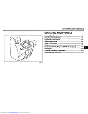
Exhaust Gas Warning
2
-
Daily Inspection Checklist
2
-
Engine Oil Consumption
3
-
Starting the Engine
4
-
Using the Transaxle
6
-
Braking
8
-
Running-In
14
-
Catalytic Converter (if Equipped)
14
-
Improving Fuel Economy
15

Suzuki SX4 SEDAN 2008 Owner’s Manual (18 pages)
Brand: Suzuki
|
Category: Automobile
|
Size: 0.67 MB
Advertisement
Related Products
-
Suzuki SX4/SX4 SEDAN
-
SUZUKI SX4 CROSSOVER —
-
Suzuki SX4 S-Ccross
-
Suzuki SX4 2012
-
Suzuki SX4 2016
-
Suzuki SX4 S-Cross 2016
-
Suzuki Canvas SQ420
-
Suzuki Splash
-
Suzuki Swift 2015
-
Suzuki Swift SF310
Suzuki Categories
Motorcycle
Automobile
Motorcycle Accessories
Musical Instrument
Offroad Vehicle
More Suzuki Manuals
-
Contents
-
Table of Contents
-
Troubleshooting
-
Bookmarks
Quick Links
WARNING/CAUTION/NOTE
Please read this manual and follow its instructions carefully. To emphasize special information, the words
WARNING
CAUTION
,
!
!
lighted by these signal words.
WARNING
!
Indicates a potential hazard that could result in death or injury.
CAUTION
!
Indicates a potential hazard that could result in vehicle damage.
NOTE:
Indicates special information to make maintenance easier or instructions clearer.
WARNING
!
This service manual is intended for authorized Suzuki dealers and qualified service technicians only.
Inexperienced technicians or technicians without the proper tools and equipment may not be able to
properly perform the services described in this manual.
Improper repair may result in injury to the technician and may render the vehicle unsafe for the driver
and passengers.
WARNING
!
For vehicles equipped with a Supplemental Restraint (Air Bag) System:
• Service on and around the air bag system components or wiring must be performed only by an
authorized SUZUKI dealer. Refer to «Air Bag System Components and Wiring Location View» under
«General Description» in air bag system section in order to confirm whether you are performing ser-
vice on or near the air bag system components or wiring. Please observe all WARNINGS and «Ser-
vice Precautions» under «On-Vehicle Service» in air bag system section before performing service
on or around the air bag system components or wiring. Failure to follow WARNINGS could result in
unintentional activation of the system or could render the system inoperative. Either of these two
conditions may result in severe injury.
• If the air bag system and another vehicle system both need repair, Suzuki recommends that the air
bag system be repaired first, to help avoid unintended air bag system activation.
• Do not modify the steering wheel, instrument panel or any other air bag system component on or
around air bag system components or wiring. Modifications can adversely affect air bag system
performance and lead to injury.
• If the vehicle will be exposed to temperatures over 93 °C (200 °F), for example, during a paint baking
process, remove the air bag system components, that is air bag (inflator) modules, SDM and/or seat
belt with pretensioner, beforehand to avoid component damage or unintended activation.
The circle with a slash in this manual means «Don’t do this» or «Don’t let this happen».
IMPORTANT
and NOTE have special meanings. Pay special attention to the messages high-
Chapters
Troubleshooting
Summary of Contents for Suzuki SX4
Мультимедийное руководство на английском языке по техническому обслуживанию и ремонту автомобиля Suzuki SX4 первого поколения.
- Автор: —
- Издательство: Suzuki
- Год издания: 2007
- Страниц: —
- Формат: MDF
- Размер: 515,3 Mb
Сборник руководств на английском языке по техническому обслуживанию и ремонту автомобиля Suzuki SX4 первого поколения.
- Автор: —
- Издательство: Suzuki Motor Corporation
- Год издания: —
- Страниц: —
- Формат: PDF
- Размер: 236,0 Mb
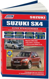
Руководство по эксплуатации, техническому обслуживанию и ремонту + каталог расходных запчастей автомобиля Suzuki SX4 2006-2013 годов выпуска с бензиновым двигателем объемом 1.6 л.
- Автор: —
- Издательство: Легион-Автодата
- Год издания: —
- Страниц: 380
- Формат: —
- Размер: —

Руководство по эксплуатации и ремонту автомобилей Suzuki SX4 и Suzuki SX4 S-Cross с 2013 года выпуска с бензиновыми двигателями объемом 1.4/1.6 л.
- Автор: —
- Издательство: Монолит
- Год издания: —
- Страниц: 448
- Формат: —
- Размер: —
Руководство по эксплуатации, техническому обслуживанию и ремонту автомобилей Suzuki SX4 и Fiat Sedici с 2006 года выпуска.
- Автор: —
- Издательство: Мир Автокниг
- Год издания: —
- Страниц: 267
- Формат: —
- Размер: —

Скачать файл PDF «Suzuki 2010 SX4 Руководство по эксплуатации» (4.51 Mb)
Популярность:
48386 просмотры
Подсчет страниц:
297 страницы
Тип файла:
Размер файла:
4.51 Mb
-
-
#1
Всем добрый день! Ищу Руководство пользователя на русском языке для автомобиля Suzuki SX4 S-Cross (Crossover), бензин 1.4 турбо, 140 л.с., автомат, выпуск май 2021 (2-е поколение). Всё, что удалось найти в Интернете, это электронные версии руководств про ремонту и эксплуатации для Suzuki SX4 (НЕ кроссовера), либо для Suzuki Vitara. Причём руководства по ремонту меня не интересуют, я не автомеханик, и сам ремонтировать узлы и агрегаты не собираюсь. Интересует руководство именно по эксплуатации, как обычного пользователя. Я живу не в России, поэтому интересуюсь либо электронной версией, либо (что предпочтительнее) — возможностью прислать мне такую книгу. В одном из московских дилерских центров ответили, что такое руководство вроде бы идёт только вместе с автомобилем, а в Сети есть версии только на английском или японском языках. И всё же не теряю надежды найти такое Руководство на русском языке, и именно для моей модели (важно отметить, что у меня — 2-е поколение кроссоверов, выпуск 05/2021, поскольку в декабре 2021-го года начали выпускать уже 3-е поколение). Благодарю всех, кто откликнется и поможет с поисками.

GERR
Сузуковод со стажем
GERR
Сузуковод со стажем
-
-
#4
там и ремонт и эксплуатация
без права доступа ссылка
А мануал там точно есть?
-
-
#5
без права доступа ссылка
А мануал там точно есть?
Есть, мне обычно сообщения приходят, предоставить права доступа. Сообщений небыло, никто не проходил по ссылке типа. https://www.drive2.ru/l/556645904577202097/ вот на драйве выкладывал два года назад.
-
-
#7
Мне больше интересна моя СХ4, хоть Витара и тоже самое на 99%.
-
-
#8
Есть, мне обычно сообщения приходят, предоставить права доступа. Сообщений небыло, никто не проходил по ссылке типа. https://www.drive2.ru/l/556645904577202097/ вот на драйве выкладывал два года назад.
Подтверждаю: «Нет права доступа».
-
-
#9
Подтверждаю: «Нет права доступа».
Перепроверьте. Но мне сообщений не приходило о запросе доступа. Гугл глючит небось… Он последнее время отвратно работать стал, все абсолютно сервисы.
GERR
Сузуковод со стажем
-
-
#10
мне обычно сообщения приходят, предоставить права доступа
отключили запрос? Скачалось напрямую.
И там нет мануала пользователя — это рук-во по эксплуатации и ремонту
Есть электронная версия для Витары
ну так давайте
-
-
#11
отключили запрос? Скачалось напрямую.
И там нет мануала пользователя — это рук-во по эксплуатации и ремонту
Там все в одном, руководство по ЭКСПЛУАТАЦИИ(в начале книги главы 1 — 4). Да, я вообще все отключил, раньше запросы приходили всегда.
Последнее редактирование: 16 Декабрь 2022
GERR
Сузуковод со стажем
-
-
#12
Там все в одном, руководство по ЭКСПЛУАТАЦИИ
Это не то. Люди хотят вариант как на бумаге заводской. У вас он есть? Разницу видите?
-
-
#13
Ну ладно, хотят — пусть ищут. Дал, что есть.
GERR
Сузуковод со стажем
-
-
#14
да это понятно, этот файл много где выложен, и на секаса и на витару.
Вот мануала толстого нигде нет
-
-
#15
отключили запрос? Скачалось напрямую.
И там нет мануала пользователя — это рук-во по эксплуатации и ремонтуну так давайте
Попробовал отправить PDF — Руководство для Витары, не получается. Видимо, из-за большого объёма.
GERR
Сузуковод со стажем
-
-
#16
Видимо, из-за большого объёма.
Сюда конечно не влезет. Выложите в облако какое-нибудь, а сюда ссылку.
Сколько размер?
GERR
Сузуковод со стажем
-
-
#19
Это то же, что и везде — книга Днепропетровского издания.
А все хотят именно оригинальный мануал от машины (толстая белая книга)

-
-
#20
Это то же, что и везде — книга Днепропетровского издания.
А все хотят именно оригинальный мануал от машины (толстая белая книга)
Вот такое, что ли, только для рестайлинга?

-
-
#21
Вот такое, что ли, только для рестайлинга?
Посмотреть вложение 205463
У меня руководство на английском, название такое же : MAGYAR SUZUKI CORPORATION LTD., только год указан 2020
GERR
Сузуковод со стажем
-
-
#22
ну да
у меня есть бумажные и на Секас, и на Витару
-
-
#23
Есть вот такое в электронном виде
-
-
#24
Есть вот такое в электронном виде
Посмотреть вложение 205525
Спасибо. Такое в электронной версии у меня тоже есть, спасибо доброму человеку с форума (Sh-keeper), недавно прислал. Но это руководство в основном по ремонту, для тех, кто самостоятельно занимается подобными операциями, а также для работников автосервиса. Я этим не занимаюсь, мне требуется обычное руководство по эксплуатации, для пользователя. Чтобы было написано и показано, где какие элементы управления, для чего они предназначены, как ими пользоваться, какие могут быть неполадки и как их самостоятельно устранить.
-
-
#25
такое только в бумажном виде есть. В электронном искал, на русском языке так и не нашел… (французский, итальянски и английский только…)
-
-
#26
такое только в бумажном виде есть. В электронном искал, на русском языке так и не нашел… (французский, итальянски и английский только…)
Вот то-то и оно. Спрашивали в дилерских центрах в Москве там отвечают, что в электронной версии нет (уверен, что врут: уж у них-то наверняка должно быть, просто, возможно, они связаны какими-то обязательствами с головной компанией Suzuki не передавать третьим лицам и не распространять), а печатный вариант на русском языке поставляется только вместе с покупаемым автомобилем. Понятно, что в Россию приходит вариант на русском языке, но я далековато от России нахожусь, мне это недоступно. Хотя японцы могли бы сообразить, что сейчас русскоязычных много по всему миру, и было бы неплохо обеспечить распространение материалов на русском, это же только в плюс компании пошло бы.
-
-
#27
Вот то-то и оно. Спрашивали в дилерских центрах в Москве там отвечают, что в электронной версии нет (уверен, что врут: уж у них-то наверняка должно быть, просто, возможно, они связаны какими-то обязательствами с головной компанией Suzuki не передавать третьим лицам и не распространять), а печатный вариант на русском языке поставляется только вместе с покупаемым автомобилем. Понятно, что в Россию приходит вариант на русском языке, но я далековато от России нахожусь, мне это недоступно. Хотя японцы могли бы сообразить, что сейчас русскоязычных много по всему миру, и было бы неплохо обеспечить распространение материалов на русском, это же только в плюс компании пошло бы.
Всё же не зря говорят: кто хочет, тот добьётся. Сегодня получил искомое Руководство пользователя. Толстое печатное издание. Издано в 2017 году (электронная версия, которую я получил ранее, она от 2013 года). Новенькая книга, русский язык. Так что не нужно всегда и безоговорочно верить, когда тебе 100 раз с уверенностью и «авторитетно» говорят — «Нет такой книги на русском языке в свободном доступе, поставляется только вместе с автомобилем при покупке в салоне». ЕСТЬ ! ЕСТЬ такое Руководство !!! И я уверен, что и в электронной версии оно существует. Ищите и обрящете.
-
140.3 KB
Просмотры: 36
-
-
#28
Сегодня получил искомое Руководство пользователя. Толстое печатное издание. Издано в 2017 году
Где смогли раздобыть, если не секрет?
-
-
#29
Где смогли раздобыть, если не секрет?
Секрета нет. Вначале спрашивал в компании Suzuki в стране своего проживания. Ответили, то же самое, что и в Москве: нету, мол, и быть не может. Затем обратился в центральное агентство Suzuki (кстати, обе организации находятся по одному и тому же адресу, в одном здании), там только спросили номер машины и почтовый адрес, и коротко ответили: «Высылаем». Вот так всё оказалось доступно, и даже бесплатно. А я ведь и в головной офис Suzuki в Японию писал, но ответа пока что так и не получил.
- 16474

Руководство по эксплуатации и техническому обслуживанию нового Suzuki SX4 new
Точки подключения Сузуки sx4
Руководство в формате PDF, на русском языке. Сведения о работе автомобиля, о функциях, связанных с обеспечением безопасности, а также требования в отношении технического обслуживания.
для скачивания нужно нажать на ссылку снизу, Файл в архиве rar
Добавлять комментарии могут только зарегистрированные пользователи.
[
Регистрация
|
Вход
]