1. Введение
1.1. Описание и исполнение терминала
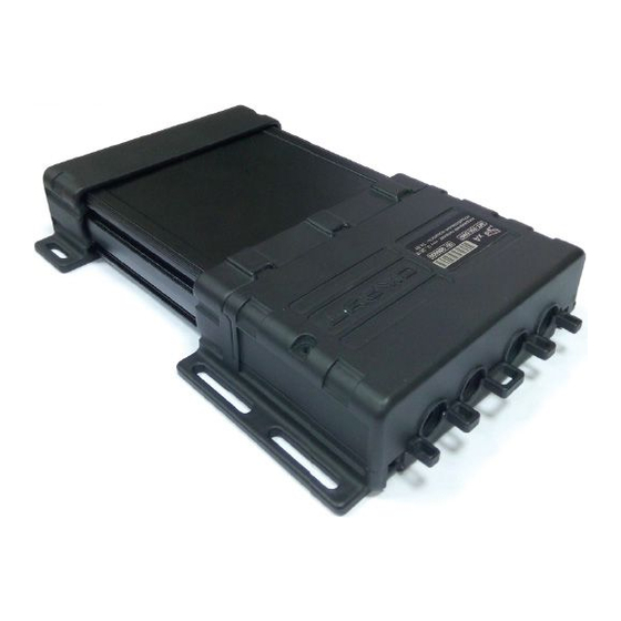
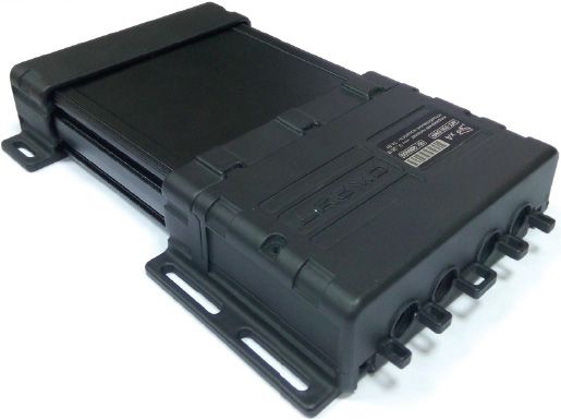
1.2. Внешний вид
1.3. Комплектация
1.4. Питание терминала
1.5. Технические характеристики МТ-700 , Технические характеристики МТ-700 ENT , MT-700 Std ATOL: Технические характеристики , Технические характеристики MT-700 STD ATOL SMART
1.6. Характеристики портов для подключения внешних устройств
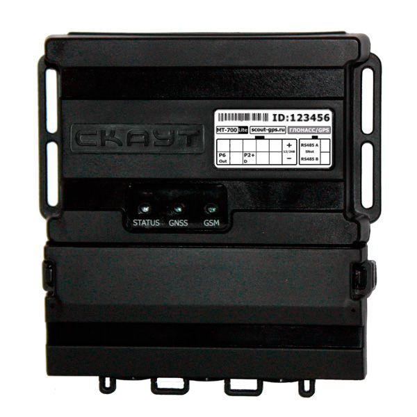
1.7. Индикация состояния
2. Функциональное описание терминала МТ-700.
2.1. Режимы работы терминалов МТ-700 и МТ-600
2.2. Универсальные порты
2.3. Порт RS-485
2.4. Порт CAN
2.5. Порт RS-232
2.6. Защита паролем и шифрование трафика
2.7. Использование голосовой связи и режим отправки SMS-сообщений с терминала МТ-700
3. Порядок монтажа терминала
3.1. Подготовка терминала МТ-700 к установке
3.2. Установка терминала
3.3. Пломбировка терминала
3.4. Установка антенн
3.5. Подключение питания терминала
3.6. Подключение дополнительных датчиков
3.7. Схема интерфейсных разъемов
3.8. Параметры искробезопасности
3.9. Проверка функционирования терминала
4. Настройка и управление терминалом
4.1. Локальная настройка
4.2. Удаленная настройка
4.3. Управление МТ-700 SMS-командами
4.4. Описание общих настроек терминала
5. Настройка портов и внутренних датчиков терминала
5.1. Описание настроек портов и внутренних датчиков
5.2. Настройка внутренних датчиков
5.2.1. Настройки навигационных приемников (порт Навигация)
5.2.2. Настройка модемов
5.2.3. Настройка акселерометра
5.2.4. Настройки протокола стиля вождения в МТ-700
5.3 Настройка портов
5.3.1. Выбор режима работы порта
5.3.2. Настройка дискретных и аналоговых входов
5.3.3. Настройка счетных и частотных входов
5.3.4. Настройка портов терминала типа ШИМ и Пиковый детектор
5.3.5. Настройки входа дифференциального расходомера
5.3.6. Настройка дискретных выходов
5.3.7. Режим индикации состояния
5.3.8. Настройка протокола 1-Wire
5.3.9 Режим блокировка двигателя для портов Р6 — Р7
5.4 Настройка цифровых датчиков уровня топлива LLS
5.4.1. Настройка МТ-700 для подключения цифровых ДУТ LLS
5.4.2. Тарирование датчиков уровня топлива
Приложение А. Соответствие контактов разъема терминала МТ-700 PRO/PRO 285 и разъема кабелей для настройки — Статья в проработке
Приложение Б. Соответствие контактов разъема терминала МТ-700 STD/ENT и разъема кабелей для настройки — Статья в проработке
Приложение В. Типовые схемы подключения
Базовая схема подключения МТ-700
Подключение питания при наличии размыкателя массы
Подключение аналогового датчика уровня топлива
Подключение частотного датчика уровня топлива
Подключение цифрового датчика уровня топлива LLS
Подключение зуммера
Подключение сигнала оборотов двигателя
Подключение считывателя iButton
Приложение Г. — Управление МТ-700 SMS-командами
Приложение Д. Эксплуатация терминала
Д.1. Условия использования терминала
Д.2. Техническое обслуживание
Д.3 Правила эксплуатации и монтажа терминала, предназначенного для использования в потенциально взрывоопасной атмосфере
Гарантийные обязательства
Приложение Е. МТ-700 изменения в прошивке 20.Х
Приложение Б МТ-700 OBD-Dongle
-
Contents
-
Table of Contents
-
Bookmarks
Quick Links
www.scout-gps.ru
МТ-700 Fleet monitoring system
Operation manual
Version 1.0
Summary of Contents for Scout MT-700 Series
-
Page 1
МТ-700 Fleet monitoring system Operation manual Version 1.0… -
Page 2: Table Of Contents
Table of contents: List of abbreviations Introduction Functional overview Tracker mounting order Terminal configuration and control Ports and internal sensors configuration Appendix A. MT-700 Pro/ Pro 285 plug and the configuration cable accordance Appendix B: MT-700 STD/ ENT plug and the configuration cable accordance Appendix C: Typical wiring schematics Appendix D: SMS-commands Mt-700 fleet tracking system…
-
Page 3: List Of Abbreviations
List of Abbreviations Terminal – onboard monitoring system МТ-700 Manual – operation manual – tracker identification number – Capability – Possible restrictions/attention – Recommended/ is required – Not recommended/ restricted – «Caution!» Mt-700 fleet tracking system…
-
Page 4: Introduction
1. Introduction Overview Hardware description Package contents Device configuration Power source recommendations Specification МТ-700 fleet tracking system…
-
Page 5
Overview The following product manual (further — “Manual”) applies to an onboard monitoring unit MT-700 Lite, Mt-700 STD, MT-700 ENT, MT-700 PRO and MT-700 PRO 285(further-tracker) manufactured by the Limited Liability Company : Осовремененные технологии мониторинга (further — LLC “CTM”). The tracker is intended for vehicle operative control that uses vehicle-monitoring systems. -
Page 6
Figure 2. МТ-700 Lite portable MT-700 PRO 285 (Lid-off) ( Figure 5 1. Microphone jack 2. Dynamic jack 3. Internal battery jack 4. Indicator LEDs 5. Non-contact tamper-switch 6. Jack lid non-contact tamper switch 7. SIM1-card lot 8. GSM antenna connector 9. -
Page 7
1. Indicator LEDs 2. Internal battery jack 3. Internal battery mounting holes 4. Non-contact tamper-switch 5. SIM-card lot 6. GSM antenna connector 7. GPS/GLONASS antenna connector 8. Buzzer 9. Scoutnet/LLS jumper connector 10. Interface jack Figure 6. МТ-700 tracker МТ-700 ENT (Lid-off) ( Figure 7 1 Indicator LEDs 2 Internal battery jack… -
Page 8
Package contents Table 1 Name of the item Amount Note Standard components Tracker GPS/GNSS antenna GSM antenna Internal backup battery External harness Safety fuse 2A passport User Manual Group Cardboard box Individual or group Additional components Panic button Optional Voice call set(microphone and dynamic) Optional … -
Page 9
Specification Table 2 Parameter Value Note Supply voltage Supply voltage , V 9 ÷ 36 Current consumption at 24 V with out data transmission, mA Current consumption at 24 V Up to 100 with data transmission, mA Autonomous operation time Up to 4 h … -
Page 10
J1708 RFID RS-232 Port LLS CAN-Log VDO Tachograph NMEA CAN (J1939, Mobileye, OBD) USB port (*)MT-700 ENT contains two RS 485 ports, one for ScoutNET protocol and the other – for LLS(or J1708,RFID) protocol. МТ-700 fleet tracking system… -
Page 11
LED indication modes Table 3 Indication mode Terminal current state «GSM» indicator Turned off Tracker malfunction Modem is switching on, searching for the — — — — — Blinks once per second network The modem is powered, the network found Blinks once every 5 seconds —————… -
Page 12: Functional Overview
2. Functional overview Tracker modes of operation I/O and interfaces Password lock Traffic encryption Voice calling SMS-commads МТ-700 fleet tracking system…
-
Page 13
Tracker modes of operation The tracker has several operational modes; transitioning between operational modes can be achieved either through universal Scout-Configurator or automatically. The inscription is on the figure: Supply voltage is below the threshold Parking Hibernation Supply voltage is over… -
Page 14
Once per second All Switches on by pushing the “Calibration” button in the Calibration Continuous state sensors “SCOUT-Configurator” software. Exits on the second push of the button. Special service mode, used for FW upgrade, settings Service changing, self-diagnostics. Exits on the mentioned commands’ completion. -
Page 15
I/O and interfaces Universal inputs МТ-700 STD, МТ-700 ENT, МТ-700 PRO, МТ-700 PRO trackers has 6(P0÷P5) tunable universal inputs, four (Р0÷Р3) of which have the voltage measuring function and 2 outputs (P6, P7); Each port can be programmed separately. MT-700 Lite has only one output(P6) and one input(P2). -
Page 16
The Scout RS-485 “Configurator” automatically carries the net number of 9, and is configured as a Master on the bus. The tracker enters a slave mode when the “Configurator”… -
Page 17
For MT-700 PRO, MT-700 PRO 285, MT-700 ENT the RS-485 port can be connected to a J1708 bus and the fuel consumption, fuel level, and other parameters can be read. J1708 access dependents on: Vehicle manufacturer Model Year of manufacture Vehicle package Onboard controller settings Before connecting to a vehicle J1708-bus it is recommended to check that… -
Page 18
RS-232 Port (LLS/Can-log/ VDO/NMEA) RS-232 supported in MT-700 PRO, MT-700 PRO 285. It can be used to connect to the following devices: digital fuel level sensors (LLS protocol), CAN-log scanner and VDO tachograph (using NMEA protocol). Up to 16 devices can be connected simultaneously. USB Port (ScoutNet) Only supported in MT-700 PRO, MT-700 PRO 285. -
Page 19
Enable «Use password for access» option is SCOUT-Server settings. Enter the key (tracker password) in the «password» in SCOUT Server settings. Figure 9. password enable … -
Page 20
Figure 10. SMS sending mode «Phone number» field is the addressee’s number in the international format (+……….) «Text» field detains the message. The messages should include only Latin symbols, digits, spaces and punctuation. «Send SMS » button sends messages. Note that using the remote configuration tracker will only send the message after the server connection. -
Page 21: Tracker Mounting Order
3. Tracker mounting order Pre-instalation of the tracker(SIM card and battery installation) Preliminary tracker settings Tracker mounting Tracker sealing Antenna connection Power connection Auxilary sensors Sparkproof parameters Terminal function test МТ-700 fleet tracking system…
-
Page 22
The tracker pre-installation (SIM card and battery installation) All action including SIM-card installment, backup battery connection and antenna installment should be conducted only while the terminal powered is off. The manufacturer is not responsible for any malfunctions that are caused by not following these rules. -
Page 23
GPRS, modem and server settings were not implemented during the mounting process, then the remote configuration can only be accomplished through the SMS-commands. The SCOUT employees’ phone numbers are embedded in the terminal’s white-list. МТ-700 fleet tracking system… -
Page 24
If white list phone numbers were not locally filled, the terminal configuration can be done only through SCOUT Tech Support. Tracker mounting The terminal should not be mounted in direct sunlight or near heaters. The best place to mount the terminal is under the dashboard, on central console or other elements inside the cabin. -
Page 25
Bottom Start here Figure 14. Rubber burn mounting Also, if the connectors’ lid is mounted, then the rubber burn should be installed under the protective lid. In order to achieve this, take the burn’s free tip and wrap the burn over the lid (anticlockwise) (Figure 15а). -
Page 26
Make sure that the terminal is working (based on the LED indication); Assemble the lids together (make sure that both latches are in place); If needed, screw the lids together. Figure 16. Cable sleeves mounting Install the tracker on the vehicle. The terminal should be anchored to stationary parts of the vehicle. -
Page 27
Figure 18 Cable zip ties. 3.1. Another option to mount the terminal is by fixing it to a horizontal tube or a beam. In order to achieve this, the zip tie should be put through the lids’ apertures and tied (Figure 19). Make sure that the tracker does not move on the zip tie. -
Page 28
Figure 21 It is forbidden to make holes in the terminal enclosure. It is forbidden to mount the tracker on the vehicle’s moving mechanisms. The terminal has an internal acceleration sensor, so mounting onto non-stationary objects may lead to incorrect tracker performance(motion and parking regimes, work regimes etc). -
Page 29
Past the seal(26×60) on lid’s junction. The seal should be put on the top lid. Make 1.1. sure it does not cover the indication LEDs. Figure 23 Thread the spiral wire through the connectors’ lid ’s apertures and the loose ends 1.2. -
Page 30
Antenna connection It is forbidden to shorten, lengthen or conjoin the antennas! Mounting the GSM antenna GSM antenna should be mounted in a place with the best radiosignal propogation. Appropriate options are: the inner side of the windshield or plastic interior parts. It is not recommended to mount a GSM antenna onto the metal parts. -
Page 31
antenna should be mounted horizontally, or have a slight angle to the horizon, with the magnet facing down, as far as possible from the radioemmiting devices (emitting antennas, radio stations, ignition block, etc). Above the antenna there should be no metal units or other entanglement parts. Possible options for mounting the GPS antenna are shown in Figure 27 If the vehicle is equipped with the windshield heating the GPS antenna… -
Page 32
Powering the tracker from the ignition wiring system is strictly forbidden! If the vehicle is equipped with the battery disconnect switch, make sure that the terminal has no connection to a vehicle’s body, for example through the auxiliary sensors. Incorrect connection may lead to the terminal failure. Terminal failure caused by incorrect connection, configuration, negligent use or unintended conditions is not covered by a warranty. -
Page 33
Temperature and others: P2, P3, P4, P5. Pulse sensors: Fuel flow meter, passenger counting sensor: Р2, Р3, Р4, P5. Tachometer: P4, P5. When connecting the non-supported sensor, you can contact the SCOUT Technical support for clarification. Sparkproof parameters Table 7… -
Page 34
GSM – once every 5 sec, or constantly on. Control using a local Configurator (Detailed in chapter 4). Connect the Configurator tie-in (subsection “local configuration”) 2.1. Launch the “SCOUT Configurator” on the laptop and go to the “Internal sensors” 2.2. tab. 2.3. -
Page 35
Figure 29. Function test using a local “SCOUT Configurator” Remote control through sever (in case of a technical feasibility). Remotely connect to the “SCOUT Configurator” 3.1. 3.2. Control that the tracker is online and sending data with the actual time and captured the satellites (Figure 30). -
Page 36
ID(test): 1.1.1.1; Pwr:24.6,4.4; OFF:8.0; 4.3. Response example: APN:internet,,; SRV:1.1.1.1:6600, SCOUTData;Unsent:0 МТ-700 fleet tracking system… -
Page 37: Terminal Configuration And Control
4. Terminal configuration and control Local configuration Remote configuration Configuration through SMS-commands General setting order МТ-700 fleet tracking system…
-
Page 38
LLC“CTM” or through the USB-port (for the МТ-700 PRO/МТ-700 PRO 285). For local and remote configuration the “SCOUT Configurator” should be used. You can read more on installing and using the “SCOUT Configurator” in the operational manual for the software. -
Page 39
Figure 31. Terminal – 485 configurator adapter 1 – Configurator 2 – USB-cable 3 ,4 – tie-in connector Figure 32. Tie in adapter Figure 33. 485 Configurator 1 –Configurator Figure 34. MT-700 – Universal 485 2 – USB cable jack Configurator adapter 3 –MT-700 adapter jack Figure 35. -
Page 40
Connecting to the “Universal Scout Configurator” using the “Universal 485 Configurator” Figure 37. Universal Configurator Connecting the terminal to the software “Universal SCOUT Configurator” should be carried out in the following order: 1. Prepare the tracker: insert a SIM card, then insert the backup battery plug, then connect the antennas. -
Page 41
Make sure that there is a device with the required ID in the device panel , then press the “configuration” button Connecting the terminal to the software “Universal SCOUT Configurator” using the “Configurator 485 v2.0” Connection the terminal to the software “Universal SCOUT Configurator” should be carried in the following order: 1. -
Page 42
Remote configuration The remote configuration is carried out through the “SCOUT-Server”, which is used to send data by the terminal. Figure 39 Launching window of the “SCOUT Configurator”. Remote connection Software “SCOUT Configurator” connects to the “SCOUT-Server” and sends an assignment for the configuration or terminal state request. -
Page 43
Configuration through SMS-commands The SMS-channel is used when local and remote configuration cannot be achieved, and for remote control of the terminal’s outputs without computer access. The phone that you use to send the commands should be submitted in the white list of the terminal (Settings>… -
Page 44
If you do not specify your APN settings to a specific terminal then you cannot connect to the server – username for the AP. Login – password for the AP. Password – AP name. «Access Point» can also be configure using a SMS-command Setapn with the following GPRS… -
Page 45
Figure 41 General settings, part 2 – parameters of the “SCOUT Server”. Terminal supports up to 3 Server connection settings connections, all of which can be individually configured. The connection type for server 2 and 3 can be changed Connection type –… -
Page 46
The duplicative connection is carried alongside the main connection. Data is transmitted to both servers independently. – IP-address or domain name of the server. Sever Address – Incoming port, configured in “SCOUT Server”. PORT – enabling the terminal-server traffic encryption. Traffic Encryption –the terminal initiates a connection to the… -
Page 47
Figure 42. General settings, part 3 – settings for scheduled connection, regardless of the amount of Scheduled connection data. – using those parameters will initiate the connection on the specified Monday, …, Sunday days. – – Up to 3 values can be specified. The terminal will Connection time 1 Connection time 3 initiate a connection at a specified time. -
Page 48
Figure 43. General settings, part 4 Ecall server settings Ecall settings is only allowed on the MT-700 PRO 285. ECall — European system of an automatic notification of a traffic accident. The system activates in case of a traffic accident (automatically or in a manual mode and sends the data, so called ECall, which includes: date and time of the activation, location, data on the vehicle, cellular provider, eCall-Qualifier —… -
Page 49
– phone number (supported format is MSISDN and short format for SMS phone number sending data using a reserved SMS-channel (used in case of the voice call failure). 5 attempts for sending data over SMS-channel is enshrined. – the vehicle type out of the dropdown list should be specified ( Vehicle type Figure 43 –… -
Page 50
device’s internal battery. It is necessary to regularly maintain and charge the car’s battery if: The vehicle is used irregularly, Is regularly parked for long periods, The vehicle is used for short time-periods, All other cases, in which the battery cannot sustain the needed voltage using the generator. -
Page 51
The backup battery voltage is restored. The supply voltage dropped down. The panic button was pushed ignition was fixated, or the power was restored. GSM connection rules – it is necessary that restoration for the for the GSM-network is in the home Home network. -
Page 52
Event service settings Figure 44. In fields: “server address”, “Port” data on the OEC server is specified. Those parameters cannot be changed by a user. In the field transferred events there are following settings: error that occur only on hardware glitches. Only critical –… -
Page 53: Ports And Internal Sensors Configuration
5. Ports and internal sensors configuration Internal sensors configuration Ports configuration Digiral LLS sensors configuration МТ-700 fleet tracking system…
-
Page 54
The internal sensors panel can configure the following service devices: GPS receiver, modem, accelerometer, voltmeters. Work description of the panel can be found in the operational manual for the “Universal SCOUT Configurator” software. The following manual will review each of the devices parameters and recommended parameters. -
Page 55
GPS receiver settings («Navigation») Figure 46. Inertial navigation In order to enable calculating the track lengths using the inertial sensor, on the panel “internal sensors” allow checkbox “Use the internal navigation”. Figure 47. Navigation Internal sensor “Navigation” has parameters: ( Figure 47 –choosing one of the five levels of the track detailing, Track detailing (… -
Page 56
– city-to city carriage with the minimum time spent in the urban areas. Used for Minimal location tracking, with no mileage counting. – any auto transportation. Standard – for auto transportation, in case of tight urban development and special Detailed equipment. -
Page 57
Figure 50. Map source Navigation-based mileage can be calculated. In order to count the mileage based on navigation, add the “Navigation mileage” sensor Figure 51. Millage based on navigation – allows you to specify the initial odometer state (in “Odometer initial value” button meters) (Figure 51) Modem settrings МТ-700 PRO 285 incorporates the embedded 3G-modem, terminals МТ-700 PRO, МТ-700… -
Page 58
The modem has the following parameters ( Figure 52 – defines the answering the call regime. Auto – means that incoming Call control button calls will be picked up automatically, port number – call will be picked up after the indicated port activation. -
Page 59
Supply voltage and backup battery voltage parameters Figure 55. Основное питание – threshold for the voltage change to create a new entry. Write threshold (mV) – accumulation length (in seconds) which is used to average the data. Filter length, s Tamper sensor parameters Figure 56. -
Page 60
Accelerometer settings Figure 58. Accelerometer settings “Automatic horizoning” checkbox includes automatic determination of a vertical, linear and lateral vehicle’s axes and refines them during the operation. Checkbox “Automatic vibration threshold” enables automatic vibration threshold configuration. Sending SMS-command Set Accelgage to the terminal with the automatic calibration enabled will disable the automatic calibration and the threshold, specified by the SMS will be applied. -
Page 61
Remote accelerometer configuration Accelerometer can be configured using SMS-commands. is executed using the CheckCalibration. Accelerometer calibration check Terminal response: ID(CheckCalibration): horizon: resultH (causeH); linear: resultL (causeL) resultH, resultL Where – are the results of the horizon setting and linear calibration: ок… -
Page 62
for the conducted using the following Setting the value accelerometer vibration threshold is setaccelgage command: id (setaccelgage): OК Response: testaccelgage can be conducted using: Accelerometer check Responded SMS: ID(TestAccelgage): State (x1, y1, z1); (x2, y2, z2); (x3, y3, z3) ID(testaccelgage): Ok (-58,42,1049); (571,-550,1540); (- Response: 640,671,442) State… -
Page 63
If a collision took place, then data is being send to the server, and the dispatcher can see it in the “SCOUT Configurator”. Also, the SMS-notification can be set up. In order to achieve this – turn on the option in (SMS-Settings > SMS-notifications) in SCOUT –Configurator. Ports configuration The Settings of the connected auxiliary devices are shown in the “PORTS”… -
Page 64
Figure 61. Ports STD and Lite versions do not have the RS232, CAN and USB. For ENT version the RS485_2 and CAN are available. “PORTS” panel sets up the terminal i/o. Each port has personal settings. Choosing the port’s mode of operation All inputs can work in one of the selected modes. -
Page 65
Figure 62. Selecting port working mode Working modes for MT-700 PRO/ MT-700 PRO 285 in the 19.х software version are shown in the Table 9. Table 9 Port/function P0-P1 P2-P5 P6-P7 RS-485 RS-232 CAN Digital input Analogue input OnlyP2 Peak detector OnlyP2 Counting input Differential flow-meter… -
Page 66
Table 10 Port/Function P0-P1 P2-P5 P6-P7 RS-485 RS-485_2* CAN* Digital input Analogue input Only P2, Р3 Peak detector Only P2, Р3 Counting input Differential flow-meter Frequency input PWM-input 1-Wire Only P3 Digital out Current state indication ScoutNet LLS FLS(Omnicomm) Drive Style J1708 VDO Tachograph Mobileye… -
Page 67
Digital inputs P0-P5 setting Digital inputs are intended to connect logic sensors, which operate in two different states – on and off, which correspond accordingly to high and low voltage levels. Such sensors are: “Ignition state”, “Panic button”, movement sensor and others. Figure 63. -
Page 68
– if the parameter is on, all the changes of the sensor is not Battery disconnect switch – counted until the battery disconnect switch is off. Figure 65. Digital input settings If the checkbox “enable the pull-up” on the P3 is enabled – then the internal pull-up is enabled. Analogue inputs settings on P0-P2 Analogue inputs are designed to measure sensors, which correspond to the change in measuring parameter to the output voltage change. -
Page 69
Figure 66. «Voltage» sensor parameters Using “Voltage” sensor ( ) the following parameters can be changed: Figure 66 Write threshold (mV) – threshold for the voltage change to create a new entry. Filter length, s – accumulation length (in seconds)to average the data. Figure 67. -
Page 70
Counting sensors on the Р2, Р3 ports Counting inputs are used to connect the pulse sensors, which are the following: fuel consumption sensor, passenger flow sensor and others. The interpretation of the counting input is the same as the one for the Analogue input Figure 66 Figure 68. -
Page 71
Figure 69 For the sensor the following settings are available: – a new entry will only be created if the difference from the Write threshold (kmph) previous value is bigger than the threshold. – the coefficient that is used to converse amount of pulses Speed conversion coefficient (с) to a speed. -
Page 72
Figure 70. «Frequency» settings Using the «Frequency» sensor (Figure 70) the following parameters are available: Write threshold (mV) – threshold for the voltage change to create a new entry. Filter length (s) – accumulation length (in seconds) to average the data. Figure 71. -
Page 73
Using the «Engine speed» sensor, a new entry will only be created if one the parameters exceeds the threshold. This provides the engine control while saving the internet traffic. PWM inputs on the Р2-Р5 ports PWM (PWM – pulse width modulation, pwm signal) is used for the that sensor. Interpretation for the PWM is the as to one for the analogue port ( Figure 66 For PWM input those sensors can be set:… -
Page 74
Peak detector is used to connect the analogue sensors, which provide the pulse signals on the output. Interpretation for the PWM are the same as on the analogue port (Figure 66) On the «peak detector» the following sensors may be set: «Voltage»… -
Page 75
Differential flow meter on Р2-Р5 ports «Differential flow meter» input is used to connect two and more paired outputs of the flow-meter Figure 77. Differential Flow meter 1-Wire sensor setting on the Р3 port 1-wire is used for sensors «Driver identification» and «Temperature». 1-Wire protocol used for sensors “Driver identification”, which provides the driver identification using the iButton reader (Dallas DS-1990A protocol) (reader mounting order is shown in scheme 9B). -
Page 76
Figure 78. 1-Wire on the P3 The buzzer can be activated by setting the «indication port» in the 1-Wire settings (Figure 78). The buzzer is connected to the specified port. Once the ignition is on, the buzzer generates a signal once every 10 seconds and the sensor signal: «Identification has not been made». -
Page 77
Filter length (s) – accumulation length (in seconds) to average the data. Digital outputs Р6-Р7 settings Digital outputs of the tracker allow you to control the external slave devices. Output is activated on the SMS-command or command from the SCOUT-Configurator. МТ-700 fleet tracking system… -
Page 78
Figure 81. Digital output parameters Using the «Digital value» the following parameters can be configured: (Figure 81): – activates the output (after the command execution). – deactivates the output (after the command execution). – if specified, the output will be active for the specified time. If the value is Pulse length «0»… -
Page 79
Figure 83. Drive style port For the «Drive Style» sensor the following parameters can be specified: – the speed value, exceeding which will lead to a one Maximal permitted speed 1 (km/h) long buzzer signal. – the speed value, exceeding which will lead to two long Maximal permitted speed 2 (km/h) buzzer signals. -
Page 80
– time, used for the fixation of the speed limits violation. Permitted speed exceed time (sec) – parameter, allowing buzzer indication on the speeding events. Speeding indication Default parameters are: 60, 90, 120 and 130 km/h accordingly. For the «Drive style» the following sensors can be set: … -
Page 81
The «Lateral acceleration» sensor has the following parameters: – acceleration threshold, exceeding which will Rightward acceleration threshold (0,001g) generate 5 short buzzer signals – acceleration threshold, exceeding which will Leftward acceleration threshold (0,001g) generate 5 short buzzer signals Turns indication – allowing checkbox will implement the indication on turns acceleration events Figure 86. -
Page 82
Acceleration slew rate on the Z axis, 0.1 mg/ms (0.1 mg/ms) – axis). Exceeding any threshold will cause data to be send to the server. The exceedance events can be seen in the SCOUT-Studio ports can be also configured through SetDriveStyle with the Drive Style on the Р6-Р7… -
Page 83
terminal output state after the blocking command. High level Output blocking state – corresponds to a «ON».state, low level – «OFF». activating the block on the disabled ignition. Engine block on ignition off – output activation on parking. Parking block– time delay before activating the output after the blocking message Block timeout (s) –… -
Page 84
Data can be retransmitted to the server. Figure 89. Data retransmission In the Data Retransmission settings ( ) the device’s net number, which data will Figure 89 retransmit, can be specified. Figure 90. Fuel Level sensor «Fuel Level» sensor ( ) has the following parameters: Figure 90 –… -
Page 85
Write threshold – threshold for the value change to create a new entry. – time(s), for averaging the values Filter length «Refueller Identification» sensor ( ) provides the driver identification using the Figure 92 RFID-reader SCOUT-DriverID. МТ-700 fleet tracking system… -
Page 86
P1(Driver ID) control – used for fuel shipment. – dialogue window for setting the white list ( «White list» button Figure 94 «Driver identification» ( ) provides the driver identification using the SCOUT- Figure 93 DriverID. МТ-700 fleet tracking system… -
Page 87
Figure 93. Driver identification sensor Net number – net number in ScoutNet (0 o 7). Outside relay control – allows you to change the specified output state if the identification was successful. Inverting signal – allows you to change the specified output state of the digital output in case identification was NOT successful. -
Page 88
«Mechanism position» and «Mechanism movement» sensors are used to set the data obtained from the (Mechanism position sensor), to gather data. The settings are analogue to the «Seat belt» settings,. For the J1708 protocol the following sensors are created: «Fuel sensor», «Fuel consumption»… -
Page 89
Figure 97. Engine speed For the «Engine speed» sensor the following parameters can be set: Running engine threshold (RPM) – minimal RPM for the motor to be considered running. Default value – 200 RPM Idle speed threshold (RPM) – minimal RPM that corresponds to a running engine (not in idle mode). -
Page 90
Figure 98. Figure 99. Navigation NMEA input has the following parameters: Minimal– city-to city carriage with the minimum time spent in urban areas. Used for location tracking, with no mileage counting. Standard – any auto transportation. МТ-700 fleet tracking system… -
Page 91
Detailed – for auto transportation in the event of tight urban development and special equipment. Special equipment– for special equipment or if the highly detailed track is needed Manual setting is giving the opportunity for a manual setting of parameters: Timeout between measurements (in seconds) –… -
Page 92
CAN interface settings МТ-700 PRO, МТ-700 PRO 285, MT-700 ENT support CAN interface with the following protocols: J1939, OBD and Mobileye. The main J1939 protocol setting CAN-bus speed. Figure 100. For the J1939 protocol the following sensors are available: «Fuel level», «Fuel consumption», «Engine speed», «Machine hours (overall) », «Axle load», «Trailer mass», «Cargo weight»… -
Page 93
Figure 102. Machine hours (overall) For the «Machine hours (overall)» only one parameter write threshold (min) Default – 60 min. Figure 103. Axle load «Axle load» has the following parameters: frontal axis. Axle number — 0 – Write threshold (kg)– threshold for the change in mass required to create a new entry. Entry timeout length, s Default setting –… -
Page 94
Write threshold (kg)– threshold for the change in mass required to create a new entry. Entry timeout length, s. Default – 4s Figure 105. Параметры датчика Общий пробег For the «Distance travelled» only one parameter can be changed write threshold Default –… -
Page 95
Vehicle speed FCW (forward collision warning) PCW (pedestrian collision warning) UFCW (urban forward collision warning) LDW (lane departure warning) HMW (headway monitor warning) Passing beam High beam Brake signal Left signal … -
Page 96
OBD protocol settings OBD protocol is used for obtaining information through the vehicle CAN-bus. Figure 108 The OBD protocol has the following parameters: should correspond the required CAN-bus (data in the busses Channel number – defers in drastic way). Vehicle model – selection from the dropdown list of the supported vehicles. OBD protocol supports the following sensors: Ignition, , , , , , , , , Check Engine. -
Page 97
Figure 109 Fuel level Write threshold (unified units) – threshold for the value(in uu)change to create a new entry. МТ-700 fleet tracking system… -
Page 98
Engine speed Figure 110 The following parameters are available for the sensor: Running engine threshold (RPM) – minimal RPM for the motor to be considered running. Idle speed threshold (RPM) – minimal RPM that corresponds to a running engine (not in idle mode). -
Page 99
Temperature Figure 111 The following parameters are available: Write threshold (C) – threshold for the value (in C)change to create a new entry. Total distance Figure 112. Total distance The following parameters are available: Write threshold (100m) – threshold for the value (in m)change to create a new entry. МТ-700 fleet tracking system… -
Page 100
no parameters can be configured ( Passing beam – Figure 113 Figure 113. Pasing beam no parameters can be configured High beam – (Figure 114). Figure 114. High beam no parameters can be configured Seat belt – (Figure 115) МТ-700 fleet tracking system… -
Page 101
Figure 115. Seat belt Vehicle speed –one parameter can be configured (Figure 116) Figure 116. Vehicle speed Write threshold (kmph) – threshold for the value (in mpph) change required to create a new entry. МТ-700 fleet tracking system… -
Page 102
no parameters can be configured Check Engine – (Figure 117). Figure 117. Check Engine RS-232 settings LLS fuel level sensors settings will be discussed in the following chapter. Can-log settings МТ-700 PRO, МТ-700 PRO 285 support on the RS232 universal CAN-LOG М444 connection. -
Page 103
Figure 118. CAN-LOG port parameters CAN-LOG has the only sensor – «Retransmission port» : By adding sensors, you can add more supported sensors to poll. VDO Tachograph settings: Tachograph VDO is used for receiving data from the VDO DTCO 3283. Figure 119. -
Page 104
LLS digital level sensors set up RS-485 supports up to 16 digital fuel level sensors. Figure 120. « LLS Fuel Level Sensor» Common parameters of the «LLS Fuel level sensor» (Figure 120) are: – sensor poll type. If the checkbox is on, the sensors are being polled Conduct sensor poll by the master (terminal). -
Page 105
Figure 122. «Temperature» LLS sensor For the “Temperature” sensor the following parameters are available: Net number – sensor net number in LLS protocol (0 o 255). Write threshold – threshold for the value change to create a new entry. Recommended — 1 Filter length –… -
Page 106
After finishing, the SPAN table can be edited in the hand mode. The table is saved automatically after the SPAN window is closed. In order to download the SPAN table onto the “SCOUT-Explorer” you need to open the analogue sensor settings and push the “get span table” button (Figure 126):… -
Page 107
Figure 126. Uploading the Span table to the SCOUT-Explorer If the table was saved in the terminal profile, then it will be uploaded for the corresponding input. МТ-700 fleet tracking system… -
Page 108: Appendix A. Mt-700 Pro/ Pro 285 Plug And The Configuration Cable Accordance
Appendix А. МТ-700 PRO/PRO 285 Jack and cable Jack acco № contact in Jack/wire color RS-485 RS-232 RS-485 RS-232 CAN Н Contact Power (-) Power (+) В ТX МТ-700 PRO 285 Jack 16 pin blue yellow black blue white grey yellow orange brown…
-
Page 109
12 pin white/ white/ Black white/ blue/ Yellow blue/ blue blue grey orange white brown Configurator jack of the МТ-700 PRO/PRO 285 16 pin желто- черно- blue- сине- white — white — white — сине- black-white green green розовый grey black purple brown… -
Page 110: Appendix B: Mt-700 Std/ Ent Plug And The Configuration Cable Accordance
Appendix B. МТ-700 STD/ENT Jack and cable Jack accordance Pin № in the Jack /wire color RS-232 RS-23 RS-485 Н RS-485 485_ 2 485_ 2 ТX Contact Power (-) Power (+) В Jack МТ-700 16 pin white/ blue white white/ yellow- black blue…
-
Page 111
Jack for the МТ-700 12 pin white/ white/ Black white/ blue/ Yellow blue/ blue blue grey orange White brown Jack МТ-700 16 pin yellow- black white — white — blue- black-white white -purple green purple brown White Jack For configuration of the МТ-700 2 pin… -
Page 112: Appendix C: Typical Wiring Schematics
Appendix C. Typical Connection schematics Basic ………………….connection schematic Analogue Fuel level sensor ……………………. Frequency Fuel level sensor …………………. ……………………fuel level sensor Buzzer ………………………. J1708 and CANJ1939 …………………… Engine Speed …………………….. iButton ……………………….
-
Page 113
Basic schematic connection The simpliest connection is: Power(-) to the Battery (-). Power(+) – through the 2A fuse to the battery (+) (pin № 30). P2 – to the wire, which provide the power only after the ignition is on (pin № 15). Figure . -
Page 114
Disconnectable battery schematic Disconnectable battery schematic Figure . 2 – Power(-) to the Battery (-) through the 3-5 A fuse. Power(+) – through the 2A fuse to the battery (+) (pin № 30). P2 – to the wire, which provide the power only after the ignition is on (pin № 15). МТ-700 fleet tracking system… -
Page 115
Analogue fuel level sensor Signal wire goes to the P0. If needed, other sensor can be connected to the 1 and 2 ports Power the sensor from the same power lines as the terminal. Analogue fuel level sensor Figure 3 — МТ-700 fleet tracking system… -
Page 116
Frequency fuel level sensor Figure 4 – Frequency fuel level sensor МТ-700 fleet tracking system… -
Page 117
Digital LLS fuel level sensor Figure 5 – digital LLS fuel level sensor МТ-700 fleet tracking system… -
Page 118
Buzzer connection Figure 6 – Buzzer connection МТ-700 fleet tracking system… -
Page 119
J1708 and CANJ1939 connection Figure 7 –J1708 and CAN J1939 connection МТ-700 fleet tracking system… -
Page 120
Engine speed sensor connection Figure 8 — Engine speed sensor connection МТ-700 fleet tracking system… -
Page 121
iButton Figure 9 – iButton connection Minus – to the common wire, data – to the P3 МТ-700 fleet tracking system… -
Page 122: Appendix D: Sms-Commands
Appendix D. SMS-commands Command Function Parameters Terminal response Request example Response example Note ID(version) Voltage is multiplied by the Power supply voltage Factor of 10 Battery voltage id(test): 1.1.1.1; Power-off threshold Pwr:24.6,4.4; APN settings OFF:8.0; Test test Terminal test Used server APN:internet,,;…
-
Page 123
force Reboot reboot id(reboot): OK reboot id(portconfig): Portconfig portconfig 0 P0: PeakDetector Port configuration Port number Port() request (VLT) порт: состояние порта Port state Id(getport): P0: Getport (значение) getport 0 request Port number PeakDetector=0 *in case the change is available OK*, Setport Port number… -
Page 124
available МТ-700 fleet tracking system… -
Page 125
установка setdefaultsett id(setdefaultsetti Setdefault ings ngs): OK заводских Settings значений Parameter setting protocol, Setserver1 Setserver1 channel (gsm, 111.222.111.22 For server 1 2,6600,passwor wifi), IP-address Port, *Parameters are changed encryption, ** Parameters Connection type incorrect Parameter setting protocol, Setserver2 Setserver2 111.222.111.22 channel (gsm, For server 2 Protocol — scoutdata,… -
Page 126
Port, scoutopen, scoutopen2, encryption, id(setserver): OK wips, egts; Connection type Imposible to Execute ** Channel — gsm, wifi; protocol, channel (gsm, encryption — 1 — on, 0 – off; Connection type- m – protocol, Parameter setting channel (gsm, Setserver3 For server 3 Setserver3 main, d –… -
Page 127
scoutopen, scoutopen2, Data channel 6600,ScoutData,cry request Server, protocol wips, egts; pto:0,m,Unsent:0 Encryption, Channel — gsm, wifi; Server 2 Testserver2 id(testserver2): Testserver2 Encryption — 1 — on, Unsent data parameters WIFI,SRV1:1.1.1.2: 0 – off request МТ-700 fleet tracking system… -
Page 128
Connection type — m 6605,ScoutData,cry pto:0,d,Unsent:0 – main, d – doubling, r — reserve. Server 3 Testserver3 id(testserver3): Testserver3 parameters WIFI,SRV1:1.1.1.3: 6608,ScoutData,cry request pto:0,r,Unsent:0 Terminal ID Terminal ID setid 123456 id(setid): OK Setid Setcalibration Id(setcalibration) Set calibration Setcalibration Mode for 5 min МТ-700 fleet tracking system… -
Page 129
установка Login, password, setapnmts,mts, id(setapn): OK Setapn параметров internet.mts.r точки доступа GPRS connect Id(connect): SRV1 Immediate Connect : processing, Server connection SRV2: processing, And data sending SRV3: off processing Id(connect): SRVx, failed connect OK via … Id(connect): SRVx, connect failed Id(connect): SRVx, connect via SRVy Remote… -
Page 130
МТ-700 fleet tracking system… -
Page 131
ClearLog id(Clearlog): OK Clear the Clearlog Telemetry log запрос Imei- id(getimei): imei GetImei id(getimei): GetImei номера 123456789012345 модема терминала port (data type): GetDriveStyle Id(getdrivestyle): Settings request GetDriveStyle P4: DriveStyle: spd1,spd2,spd3,spd4,Ac For the drive style Port number CelBrake 60,90,110,130,250, port port – port number spd1,spd2,spd3 — МТ-700 fleet tracking system… -
Page 132
Maximal speed limits 1, 2, 3 SetDrivestyle Id(setdrivestyle): Dryve style port SetDriveStyle Accel — acceleration 4,60,90,120,25 Оk configuration threshold 0,300 Port number Brake – deceleration spd1,spd2,spd3, threshold Accel,Brake Angle in Static coordinates LinearCalibrat Id(linearCalibrate): accelerometer If empty — linear LinearCalibrate Оk Impossible linear… -
Page 133
Error calibration reset impossible МТ-700 fleet tracking system… -
Page 134
ID – tracker ID Acc – current acceleration Ang – angle to the horizon Xc,Yc,Zc – current “Raw” Data on the 3 axes Xh,Yh,Zh – calibration vector Xl,Yl,Zl – linear acceleration calibration Id(getacceleration):accel(a ID(getacceleration): Accelerometer cc), angle(4), current МТ-700 fleet tracking system… -
Page 135
(-59,52,1039), GetAcceleration angle(ang),current(Xc,Yc,Z Current state getacceleration horizon(14,-22, request horizon(Xh,Yh,Zh),line(Xl,Y 1044), line(not l,Zl) calibrated) МТ-700 fleet tracking system… -
Page 136
Command Function Parameters Terminal response Request example Response example Comment state – calibration state not calibrate – no horizon line detect – horizon — OK Threshold – vibration threshold ID(getaccelgage): ID(GetAccelgage) state, GetAccelgage getaccelgage line detect, 5 threshold МТ-700 fleet tracking system… -
Page 137
settinng accelerometer Vibration threshold значение SetAccelgage ОК SetAccelgage 15 id(setaccelgage): OK порога gravity – 3D vector horizon: (0, 10, statistics A – liner statistics vector Statistics not ready 1030); linear: angle request GetStatistics GetStatistics 40, vectors horizon: (gravity); linear: angle A , vectors V (P%), (lineVector) 120(58%), (149, 23, МТ-700 fleet tracking system… -
Page 138
МТ-700 fleet tracking system… -
Page 139
Linear calibration Statistics reset МТ-700 fleet tracking system… -
Page 140
ResetStatistics ОК ResetStatistics id(ResetStatistics): id(setcalibration):O Adding the number to the terminal’s white Setwhitelist list Phone number ОК Setwhitelist Id(setcalibration):f +79997170944 FAIL ID(testaccelgage): проверка ID(TestAccelgage): State (x1, Ok (-58,42,1049); TestAccelGage ТestAccelgage работоспособности y1, z1); (x2, y2, z2); (x3, y3, (571,-550,1540); (- акселерометра… -
Page 141
ID(CheckCalibration) МТ-700 fleet tracking system… -
Page 142
: horizon: ок (line ID(CheckCalibration):horizon: accelerometer 22, side 27); CheckCalibratio resultH (causeH); linear: calibration CheckCalibration linear: ок(angle resultL (causeL); check 3.25) МТ-700 fleet tracking system… -
Page 143
МТ-700 fleet tracking system… -
Page 144
horizon Horizon ОК Horizon ID(horizon): OK ID(testmemory): Processing… МТ-700 fleet tracking system… -
Page 145
ID(testmemory): Checked ID(testmemory): Testmemory testmemory Memory test pages X, errors Y, times Z sek Checked pages 1024, errors 0, times 150 установка Целевые Setodm Setodm 167,7 показаний показания ОК Id(setodm): OK одометра одометра Enable/disiable Power-off mode Power-off voltagesafety id(voltagesafety): Voltagesafety 1,12.9 enable МТ-700 fleet tracking system… -
Page 146
МТ-700 fleet tracking system… -
Page 147
id(getregstat): 25002;GSM:home,lac:0 Operator code, registration Network registration Getregstat getregsat x1E7D,cid:0x16CB;GPR status, lac, cid Status request S:home,lac:0x1E7D,ci d:0x16CB МТ-700 fleet tracking system… -
Page 148
Password setting setpassword Setpassword qwerty123 id(setpassword): OK password ОК For the tracker IP address scoutdata Protocol change to port ScoutData 111.222.111.222, id(scoutdata): OK ScoutData password 6600,password МТ-700 fleet tracking system… -
Page 149
МТ-700 fleet tracking system… -
Page 150
scoutopen IP address Protocol change to port ScoutOpen 111.222.111.222, id(scoutopen): OK ScoutOpen password 6600,password IP address port egts МТ-700 fleet tracking system… -
Page 151
password Egts 111.222.111.222, id(egts): OK Protocol change to 6600,password EGTS wips Protocol change to IP address WIPS 111.222.111.222, id(wips): OK WIPS port 6600,password password МТ-700 fleet tracking system… -
Page 152
Autohorizon AutoHorizon setting ОК AutoHorizon id(AutoHorizon): OK enable МТ-700 fleet tracking system… -
Page 153
Log sending SendLogAgain request ОК sendlogagain id(sendlogagain): OK Disconnect id(CheckVdo): VDO tachograph No connection CheckVdo CheckVdo Disconnect Connection test Connect Modem Modem id(getmodem): identification GetModem identification getmodem Quectel_Ltd check Approximate terminal id(getcellpos): http://www.open- location electronics.org/cell (based on cell ID Getcellpos getcellpos Map hyperlink МТ-700 fleet tracking system… -
Page 154
track/cell.php?hex=0 Location) &mcc=250&mnc=99&lac= 14756&cid=10212 МТ-700 fleet tracking system… -
Page 155
МТ-700 fleet tracking system…

ОТПРАВИТЬ ЗАЯВКУ
Автомобильный трекер СКАУТ МТ-700 DVR объединяет в себе функции мониторинга транспорта и автономного 4-х канального видеорегистратора.
ГК «СКАУТ» разрабатывает и выпускает собственную линейку оборудования для спутникового GPS/ГЛОНАСС мониторинга транспорта. В 2014 году мы начали выпуск нового поколения навигационных модулей мониторинга – МТ-700, которые приходят на смену предыдущей серии МТ-600.
Устройства, входящие в состав Системы СКАУТ, обеспечивают отслеживание параметров работы транспорта, передачу и запись в базу данных информации о местоположении и режиме работы транспорта, состоянии грузов и других объектов, обеспечивают информирование диспетчеров и водителей, работу «тревожной кнопки» в случае возникновения нештатных ситуаций.
Функциональные возможности трекера MT-700 DVR:
- Передача данных с трекера на сервер по каналам GSM/GPRS в том числе по протоколу EGTS
- Настраиваемый порог создания записи при изменении входного аналогового сигнала
- Функция «черный ящик» – запись данных о местоположении и состоянии датчиков в энергонезависимую память терминала при потере сигнала сотовой сети и последующая автоматическая передача записанной информации при восстановлении связи
- Емкость памяти (черного ящика) абонентского терминала – 32 Мб
- Встроенный датчик ДТП, соответствующий требованиям РСА
- Удаленное конфигурирование и обновление встраиваемого ПО (прошивки) модуля мониторинга MT-700 DVR по GPRS с рабочей станции администратора
- Оперативная диагностика работоспособности с помощью встроенных светодиодов (индикация режима питания трекера, работы GPS/ГЛОНАСС, GSM и соединения с сервером)
- Поддержка SMS-команд для удалённой настройки подключения и удаленного управления
- Возможность отправки SMS-сообщений (в том числе удаленной) на произвольный номер
- Возможность удаленного включения/выключения выходов по команде из СКАУТ-Конфигуратор
- Встроенный 3-х осевой акселерометр и гироскоп для определения факта движения транспортного средства и определения стиля вождения
- Датчик вскрытия корпуса – определение факта вскрытия трекера MT-700 DVR с привязкой к месту и дате
- Возможность передачи на сервер результатов самодиагностики и отображение обнаруженных ошибок с помощью изменения состояния дискретного выхода
- Выдача отладочной информации модуля мониторинга MT-700 DVR в режиме онлайн в порт ScoutNet и сохранение ее в журнал при обнаружении нештатных событий. Журнал может быть запрошен удаленно и локально
- Поддержка SMS с запросом текущего состояния
- Встроенный датчик температуры, с возможностью измерения температуры терминала
- Возможность отправки SMS сообщения при следующих событиях:
- начало движения;
- изменение курса на заданную величину;
- превышение скорости;
- увеличение пройденного пути на заданную величину;
- изменение состояния входов;
- подозрение на ДТП;
- срабатывание тревожной кнопки.
- Подсчёт пробега терминалом и передача его на сервер
- Специальный разъём трекера MT-700 DVR для проведения диагностики неисправностей и определения причин выхода из строя «на месте»
- Возможность фото- и видеофиксации посредством подключения до 4-х аналоговых камер
- Возможность вывода изображения с камер на аналоговый монитор
- Возможность определения факта саботажа камер путем анализа наличия движения в кадре
- Возможность наложения на изображение сервисной информации (навигационные данные, показания датчиков, статусная информация и т. д.)
- Возможность передачи на сервер по протоколу FTP требуемых фото файлов из памяти модуля мониторинга МТ-700 DVR по запросу
- Циклическая запись фото и видео файлов на две SDXC карты памяти объемом до 256 Гб (у одной есть возможность пломбировки)
- Создание специальных *.GPX файлов к каждому отрезку видео, содержащих всю необходимую информацию для анализа записи (Госномер ТС, идентификационный номер терминала, навигационная информация, показания датчиков устройства, включая датчик ДТП)
- Возможность защиты любых сохраненных на картах памяти файлов от стирания по команде или по событиям терминала
- Возможность извлечения и замены одной из SDXC карт памяти без вскрытия основного корпуса трекера МТ-700 DVR
ФУНКЦИИ ВИДЕОРЕГИСТРАТОРА
- Подключение до 2-х CVBS камер (опционально до 4-х)
- Фотографирование по событию и по запросу
- Запись видео на 2 карты памяти до 256 Гб каждая (внешняя SD и встроенная microSD)
- Подключение аналогового монитора (опционально цифрового)
ФУНКЦИИ ТЕРМИНАЛА
- ГЛОНАСС/GPS/GSM
- Датчик стиля вождения
- Датчик ДТП
- Удалённая диагностика и конфигурирование
- Счётчик пробега
- Встроенный зуммер
- Поддержка протокола EGTS
- Датчик вскрытия корпуса
- Подключение гарнитуры голосовой связи
КОНСТРУКЦИЯ ТРЕКЕРА MT-700 DVR:
- Надежный металлический корпус, защищающий трекер от механических повреждений и обеспечивающий отвод тепла с силовых элементов устройства
- Торцы корпуса закрыты пластиковыми крышками, обеспечивающими доступ к разъемам изделия с одной стороны, SIM-карте и SD-карте памяти – с другой. Доступ к картам осуществляется без вскрытия основного корпуса модуля мониторинга МТ-700 DVR
- Крышка разъемов имеет возможность пломбировки
- Три специальных отверстия в защитной крышке для ввода кабеля в стандартной гофрированной трубе
- Множество элементов и вариантов крепления трекера к ТС
- Разъемы с защитой от саморазъединения
- SMA разъемы для подключения к трекеру GSM и GPS/ГЛОНАСС антенн
- Разъемы для подключения сигналов и питания 2-х аналоговый видео камер (опционально до 4-х)
- Разъем для подключения аналогового монитора
- Разъемы для подключения гарнитуры голосовой связи
- Четыре световых индикатора, выведенных наружу и доступных без вскрытия корпуса
УСТОЙЧИВОСТЬ И СОВМЕСТИМОСТЬ МОДУЛЯ МОНИТОРИНГА МТ-700 DVR:
- Соответствует требованиям по устойчивости к электромагнитным помехам по ГОСТ 28751-90 (степень жесткости IV)
- Соответствует требованиям по устойчивости к электромагнитным и электростатическим помехам по ГОСТ 29157-91 и ГОСТ 50607-93
- Соответствует требованиям по электромагнитной совместимости по ГОСТ 30429-96, ГОСТ 28279-89, ГОСТ Р 51318.22-99 и ГОСТ Р 51318.24-99
- Соответствует требованиям по устойчивости к климатическим и механическим факторам по ГОСТ 16019-2001
- Соответствует требованиям по безопасности ГОСТ Р МЭК 60065-2009
Сделать заказ
Если Вы определились с решением, мы готовы записать Вас на
установку в сервисный центр.

Менеджер

Менеджер

Менеджер
Сопутствующие товары
Наши клиенты довольны качеством нашей работы
Модуль мониторинга СКАУТ МТ-700 lite
Автомобильный трекер MT-700 Lite – содержит базовый набор функций, позволяющих контролировать перемещение транспортных средств, скорости, направления движения, длительности и мест стоянок автомобиля.

Облачная система контроля транспорта СКАУТ 365
Это система мониторинга, созданная на основе ПО «СКАУТ-Платформа». Обеспечивает клиентам круглосуточный контроль над автопарком без затрат на администрирование и серверное оборудование.
Содержание
- Подключение питания при наличии размыкателя массы МТ-700
- Базовая схема подключения МТ-700
- Схема интерфейсных разъемов МТ-700
- Подготовка терминала МТ-700 к установке
- Установка АКБ и SIM-карты
- Предварительная настройка терминала
- Описание и исполнение терминала МТ-700
- Описание терминала
- Исполнения терминала
Подключение питания при наличии размыкателя массы МТ-700
Схема подключения питания в случае, если автомобиль оборудован выключателем массы.
Рисунок 1 – Схема подключения МТ-700 STD c двумя разъемами
Рисунок 2 — Схема подключения МТ-700 STD c одним разъемом
Провод питания терминала «−» подключается непосредственно к минусовой клемме аккумулятора, через предохранитель 3-5 ампер.
Провод питания терминала « + » подключается через предохранитель 3-5 ампер к плюсовой клемме аккумулятора или к неотключаемому проводу питания автомобиля (контакт 30).
Порт P2 подключается к проводу зажигания через дополнительное реле согласно схеме, для исключения ложного определения факта включения зажигания.
Источник
Базовая схема подключения МТ-700
Рисунок 1 – Базовая схема подключения МТ-700 STD c двумя разъемами
Рисунок 2 — Базовая схема подключения МТ-700 STD с одним разъемом
Простейший вариант подключения:
- Провод питания терминала «−» подключается к минусовой клемме аккумулятора, или к кузову автомобиля.
- Провод питания терминала «+» подключается через предохранитель к плюсовой клемме аккумулятора или к неотключаемому проводу питания автомобиля (контакт 30)..
- Порт P2 подключается к проводу, на котором появляется напряжение питания при включении ключа зажигания в положение IGN (контакт 15).
Источник
Схема интерфейсных разъемов МТ-700
Схема интерфейсного разъема (вид со стороны контактов терминала) показана на рисунке 1, Назначение контактов для разных исполнений приведено в таблице 1.
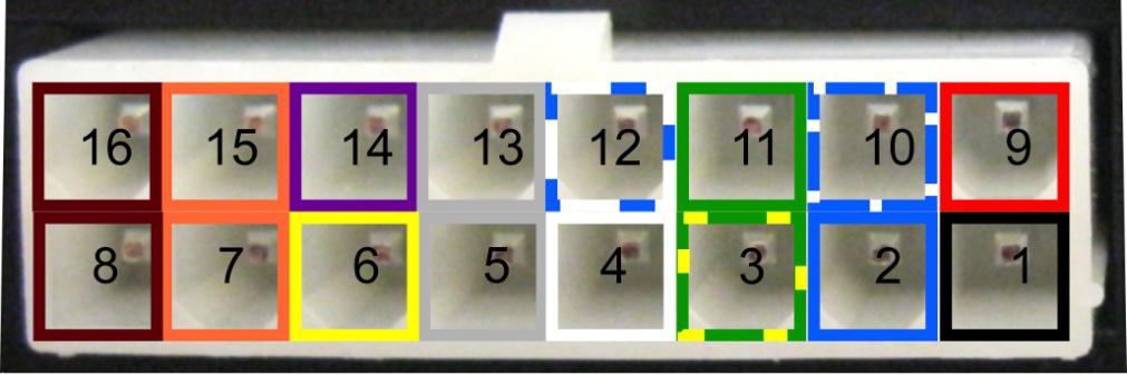
Рисунок 1 — Интерфейсный разъём
Цвет провода
Маркировка провода на шильде
Маркировка провода на шильде
Маркировка провода на шильде
Минусовой контакт питания
Минусовой контакт питания
Минусовой контакт питания
Универсальный порт 0 (с функцией измерения напряжения)
Универсальный порт 0 (с функцией измерения напряжения)
Универсальный порт 0 (с функцией измерения напряжения)
Универсальный порт 2 (с функцией измерения напряжения)
Универсальный порт 2 (с функцией измерения напряжения)
Универсальный порт 2 (с функцией измерения напряжения)
Выходной порт (открытый коллектор)
Выходной порт (открытый коллектор)
Выходной порт (открытый коллектор)
С и н и й с б е л о й п о л о с о й
Б е л ы й с с и н е й п о л о с о й
Универсальный порт 1 (с функцией измерения напряжения)
Универсальный порт 1 (с функцией измерения напряжения)
Универсальный порт 1 (с функцией измерения напряжения)
Выходной порт (открытый коллектор)
Выходной порт (открытый коллектор)
Выходной порт (открытый коллектор)
Кабель МТ-700 не может быть использован при замене на МТ-600. Связано это с тем, что это принципиально разные разъемы и сами устройства обладают разными характеристиками. Необходимо еще раз уточнить, что невозможно поставить переходник от МТ-700 на бывшее место МТ-600, поскольку оборудование полностью отличается друг от друга (разное количество портов, разных их характеристики).
Для подключения МТ-700 Std с двумя разъёмами MF-12MRA (основным 12-тиконтактным) и MF-4MRA (дополнительным 4-х контактным) используются соответственно 12-ти контактный кабель с колодкой ответный SC.01.07.31-01 (с разъемом MF-12F) и 4-х контактный кабель с колодкой ответный SC.01.07.41-01 (с разъемом MF-4F).
Для подключения МТ-700 Std/ PRO/PRO 285 с одним разъёмом MF-16MRA c используется 16-ти контактный кабель с колодкой ответный SC.01.09.31-01 (с разъемом MF-16F).
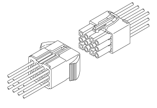
Рисунок 2 – Схема интерфейсных разъемов МТ-600
Источник
Подготовка терминала МТ-700 к установке
Установка АКБ и SIM-карты
Все действия, касающиеся установки и снятия SIM-карт, резервного аккумулятора, а также подключения и отключения антенных разъемов, должны производиться ТОЛЬКО ПРИ ОТКЛЮЧЕННОМ ПИТАНИИ!
Производитель не несет ответственности в случае выхода терминала из строя при нарушении этих требований.
Не устанавливать терминал в местах, подверженных повышенному нагреву – это может привести к выходу из строя резервного аккумулятора!
Перед включением и настройкой необходимо подготовить терминал. Для этого:
- Снимите крышку разъемов (в случае установки мобильного терминала с крышкой разъемов), открутив отверткой два винта и/или нажав на защелки верхней части крышки разъемов.
- Снимите верхнюю часть корпуса, открутив отверткой 4 винта с нижней части корпуса (Рис. 1).
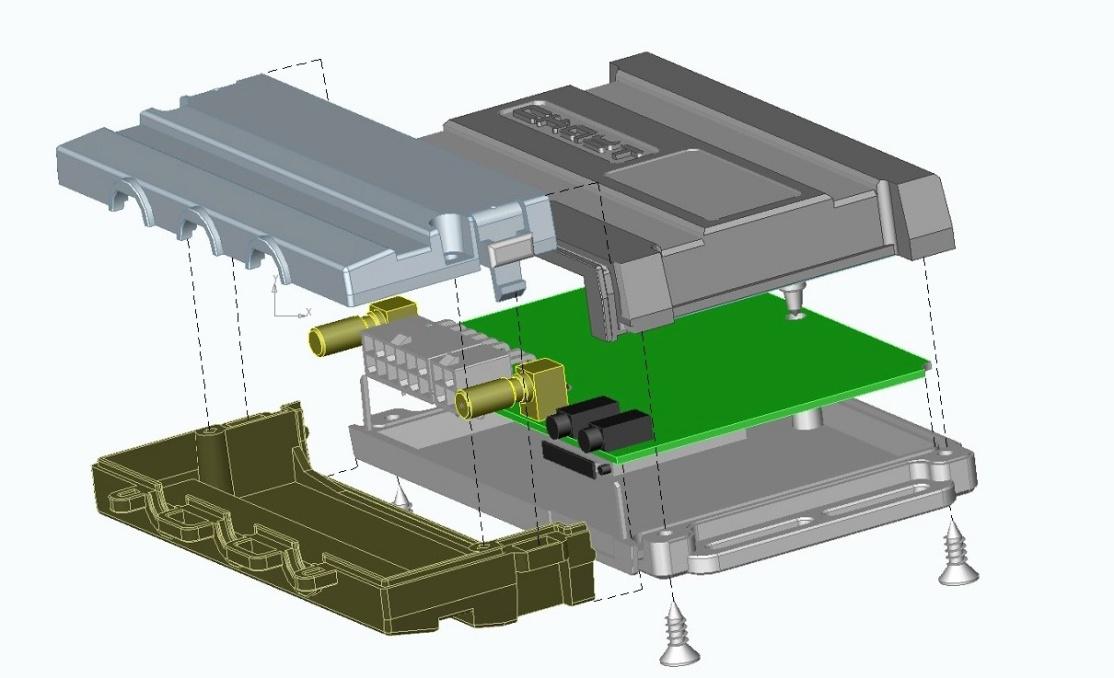
Рисунок 1 — Разборка терминала
- Вставьте провод резервного аккумулятора в разъем (Рис. 2). При необходимости длительного хранения терминала рекомендуется отсоединить провод резервного аккумулятора для продления срока его службы.
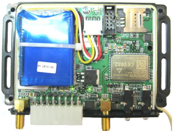
Рисунок 2 — Подключение АКБ
- Соберите верхнюю и нижнюю части корпуса, зафиксировав их 4 винтами.
- Подготовьте SIM-карту: убедитесь в доступности необходимых услуг, таких как GPRS/HSDPA, SMS, голосовые вызовы, роуминг и т.д. Проверьте наличие средств на счете. Отключите запрос PIN-кода, если этот запрос активирован по умолчанию.
- Нажмите на кнопку извлечения SIM-карты (Рисунок 3) и извлеките лоток для SIM-карты.
- Вставьте SIM-карту в лоток контактной площадкой чипа вверх, ориентируясь на скошенный угол SIM-карты в неподвижной части держателя.
- Вставьте лоток с SIM-картой в соответствующее отверстие корпуса, убедившись, что лоток задвинут до конца в корпус и самопроизвольно не вытаскивается.
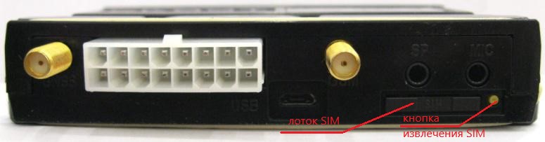
Рисунок 3 — Вид на терминал со стороны разъемов
Предварительная настройка терминала
Настройте терминал любым удобным способом (локально , удаленно либо с помощью смс-команд ).
До выполнения монтажа необходимо настроить следующие параметры:
- настройки GPRS:
- логин,
- пароль,
- точка доступа.
- настройки модема:
- телефонные номера для управления SMS-командами.
- настройки подключения к серверу:
- IP-адрес,
- Порт.
- настройки условий подключения, настройки портов – в зависимости от требуемого режима работы и подключаемых датчиков и устройств.
Терминалы имеют функцию удаленного конфигурирования, а также возможность настройки с помощью SMS-команд, т. о., если до монтажа терминала не ввести корректные настройки GPRS, модема и подключения к серверу, то дистанционная перенастройка будет возможна только при помощи SMS-команд.
В терминале с заводскими настройками белыми номерами являются номера сотрудников ГК «СКАУТ».
Источник
Описание и исполнение терминала МТ-700
Настоящее руководство по эксплуатации (далее – «Руководство») распространяется на бортовой Модуль мониторинга МТ-700 Lite , MT -700 STD , MT -700 ENT , MT -700 PRO и MT -700 PRO 285 (далее – «терминал») производства ООО «Современные Технологии Мониторинга» и определяет порядок установки, подключения и настройки, а также содержит описание функционирования терминала.
Настройка и монтаж терминала должны осуществляться согласно руководству специалистами, прошедшими обучение по установке дополнительного электрооборудования на транспортные средства (далее – «ТС») и знакомыми с техникой безопасности при осуществлении монтажных и ремонтных работ на автотранспорте.
Производитель оставляет за собой право вносить изменения, затрагивающие функциональность или характеристики терминала, без предварительного уведомления.
В данной версии руководства описана функциональность терминала с версией программного обеспечения 19.x.
Рисунок 1 — Терминал МТ-700 STD / МТ-700 ENT / МТ-700 Lite
Рисунок 2 -Терминал МТ-700 PRO / МТ-700 PRO 285
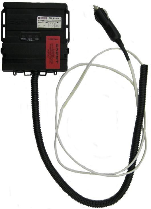
Рисунок 3 — Терминал МТ-700 Lite переносной
Рисунок 4 — Т ерминал МТ-700 с крышкой разъемов
Рисунок 5 -Тер минал МТ-700 с крышкой разъемов и гофрированными трубками для ввода кабеля
Описание терминала
Терминал предназначен для оперативного контроля транспортного средства в системах мониторинга транспорта. Терминал предназначен для работы с ТС, при питании от бортовой сети с номинальным напряжением 12 или 24 В. Терминал имеет возможность управления подключенными к нему исполнительными устройствами.
Работа терминала основана на использовании спутниковой навигационной системы GPS/ГЛОНАСС и канала сотовой связи GSM/UMTS. МТ-700 с помощью антенны GPS/ГЛОНАСС принимает сигналы от навигационных спутников, определяет по ним текущее время, координаты, направление движения, скорость, формирует по этим данным сообщения и записывает их во внутреннюю память. Терминал опрашивает подключенные к нему датчики и формирует сообщения об их состоянии. Накопленные данные передаются по каналу сотовой связи GSM/GPRS на сервер системы мониторинга и сохраняются в базе данных, после чего они доступны пользователю для просмотра в диспетчерской программе.
Для передачи данных, приема голосовых вызовов и SMS команд используется сотовый канал связи GSM. Работа терминала возможна только при использовании исправной, активированной и не заблокированной оператором сим-карты, с активированным пакетом необходимых услуг (пакетная передача данных, SMS, роуминг и голосовой вызов для терминалов PRO ).
Исполнения терминала
Терминал выпускается в следующем исполнении:
- MT-700 Lite – модуль с одним дискретным входом, одним управляемым выходом, одним цифровым интерфейсом, назначение которого — работа по протоколу ScoutNet; с гибридным ГЛОНАСС-GPS приемником и одним держателем для SIM-карт;
- MT-700 Std – модуль с одним цифровым интерфейсом, основное назначением которого является работа по протоколу ScoutNet, также к интерфейсу можно подключить ДУТ с протоколом LLS; с гибридным ГЛОНАСС-GPS приемником и одним держателем для SIM-карт;
- МТ-700 ENT – модуль с двумя цифровыми интерфейсами RS-485, один из которых работает по протоколу ScoutNet, другой – либо по LLS, либо по J1708, отдельным интерфейсом CAN, способным обрабатывать данные по протоколам J1939, OBD и Mobileye. Имеет гибридный ГЛОНАСС-GPS приёмник и один держатель для SIM;
- MT-700 PRO 285 – полнофункциональный модуль мониторинга с гибридным GPS/ГЛОНАСС-приемником. Удовлетворяет требованиям приказа Минтранса РФ от 31 июля 2012 г. №285;
- MT-700 PRO.
Источник
Adblock
detector
Note for Owners:
Guidesimo.com webproject is not a service center of Scout trademark and does not carries out works for diagnosis and repair of faulty Scout MT-700 Series equipment. For quality services, please contact an official service center of Scout company. On our website you can read and download documentation for your Scout MT-700 Series device for free and familiarize yourself with the technical specifications of device.
More Measuring Instruments Devices:
-
Endress+Hauser Cerabar S PMC71
BA00274P/00/EN/16.1471260321valid from Software version:02.20.zzOperating Instructions – Description of Instrument FunctionsCerabar S PMC71, PMP71/75 Deltabar S FMD76/77/78, PMD70/75Deltapilot S FMB70Process pressure / Differential pressure, Flow / Hydrostatic …
Cerabar S PMC71 Transmitter, 156
-
Bender iso685
T MDocument NAE1018021 • 09.2014 • © Bender Inc. • Page 1/1 • Side 1/2Bender Inc. • USA: 800.356.4266 / 610.383.9200 / [email protected] • Canada: 800.243.2438 / 905.602.9990 / [email protected] • www.bender.orgiso685Installation Bulletin / Reference GuideThis document is intended as a reference guide for installing and using a BENDER iso685 groun …
iso685 Security Sensors, 2
-
Xtralis OSID
Installation Sheet — OSID Smoke Detection SystemDetach Mounting Bracket and Front Cover. • ToDetachtheunitfromtheMountingBracket(A),openthefrontcoverandwithascrewdriverpushthelipbackwardstothenslidetheunituptodetachfromtheMountingBracket• ToprovidecableaccesstotheTerminati …
OSID Smoke Alarm, 2
-
Bender ISOMETER isoPV425 with AGH420
ENManualISOMETER® isoPV425with AGH420 coupling deviceInsulation monitoring device for unearthedDC circuits (IT systems)for photovoltaic systems up to 3(N)AC, AC 690 V / DC 1000 VSoftware version: D404 V2.xxisoPV425_D00028_09_M_XXEN/05.2018 …
ISOMETER isoPV425 with AGH420 Controller, 68