
-
Bookmarks
Quick Links
USER MANUAL
USER MANUAL
USER MANUAL
USER MANUAL
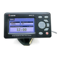
BNW — 50
Bridge Navigational Watch Alarm System
Rev. M00-0481-00
1
Summary of Contents for Samyung BNW — 50
-
Page 1
USER MANUAL USER MANUAL USER MANUAL USER MANUAL BNW — 50 Bridge Navigational Watch Alarm System Rev. M00-0481-00… -
Page 3
CAUTION 1. This BNWAS can be switched ON/OFF or settings can be changed with password, therefore only authorized person (captain) can change or switch ON/OFF the BNWAS. 2. Before operating the machinery, you must read and be fully aware of the safety signs and the guidelines.
Похожие релизы
| # | Тема | Форум | Автор |
|---|---|---|---|
|
RU |
ГМССБ УКВ SAMYUNG STV-160 — Samuyng [2010, PDF] |
Библиотека судоводителя | |
|
RU |
Организация службы на судах — Кузьмин В.Д. [2016, PDF] |
Учебные материалы | Vitbar192 |
|
EN |
Система управления клапанами Emerson PD Series 600 — EMERSON [2018, PDF] |
Судовая автоматика | Nimnul72 |
|
RU |
Котлоагрегаты КГВ — М. Руководство по эксплуатации систем управления. 419-26… |
Судовые паровые котлы | mex_111 |
|
RU |
Модель-камора №2 — Медведева и.А. (редактор) [2018, PDF] |
Морская периодика | 5sb1 |
|
RU |
Руководство к мачтовому искусству (чертежи) — не известен [1861, JPEG] |
1800 — 1900 | 5sb1 |
|
RU |
Двухтактные Двигателя с Электронным Управлением_ — MAN B&W ME Engines [2018, MP4] |
Видео для судомехаников | sevkavros |
|
RU |
Правила проектирования, постройки, ремонта и эксплуатации спортивных парусных судов, … |
Проекты, дизайн, постройка | Vitbar192 |
|
RU |
Видеоуроки яхтинга школы Sailing Time [2018, MP4] |
Видео по яхтингу и катерам | mak506 |
|
RU/EN |
Appendix для штурманов — Борискин О.И. [2016, PDF] |
Навигация | Vitbar192 |
- Ответить
- Manuals
- Brands
- Samyung Manuals
- Security System
- BNW — 50
Manuals and User Guides for Samyung BNW — 50. We have 1 Samyung BNW — 50 manual available for free PDF download: User Manual
Samyung BNW — 50 User Manual (64 pages)
Bridge Navigational Watch Alarm System
Brand: Samyung
|
Category: Security System
|
Size: 1.81 MB
Advertisement
Advertisement
Related Products
Samyung Categories
![]()
GPS
Fish Finder
Marine Radio
Marine Equipment
![]()
Telephone
More Samyung Manuals
Page 1 — BNW — 50
1 USER MANUAL BNW — 50 Bridge Navigational Watch Alarm System Rev. M00-0481-01
Page 2
10 2.2.2 VISUAL INDICATION If not “RESET” during this dormant period (3~12 minutes), visual indication will be initiated for the next 15 seco
Page 3 — QUICK USER MANUAL
11 CHAPTER 3 PRODUCT SPECIFICATION 3.1 DISPLAY UNIT (BNW-50) SCREEN SIZE ……………… 4.3 INCH TFT COLOR LCD, 480 X 272 PIXELS POWER CONSUM
Page 4 — SIGN DESCRIPTION
12 3.4 ALARM UNIT (BNW-53) POWER CONSUMPTION ……………… max 30mA / unit (24V DC) SIZE ……………… 126x90x30 mm (H x W x D) WEIGHT
Page 5
13 3.6 COMPONENTS 3.6.1 BNW-50 SPECIFICATION NO NAME MODEL NAME QUANT REMARK 1 Display unit desktop BNW-50 1 SET Bracket, protection c
Page 6
14 CHAPTER 4 BNW-50 (DISPLAY UNIT) — Rated input voltage DC 24V (NOTE) Program version may change without notice for performance improve
Page 7
15 System stops operating and goes into sleep mode by pressing this button and entering the password. In order to deactivate the
Page 8 — CHAPTER 1 ABOUT BNWAS
16 4.3 OPERATION SCREEN BNW-50’s current operational status appears on the screen. From menu, press ESC then will move to the operati
Page 9 — 2.1 OPERATIONAL MODES
17 4.4.1 OPERATION SETUP You can change and save the Operational mode, the dormant period, the delay between the 2nd & 3rd stage al
Page 10 — 2.4 EMERGENCY CALL
18 Activated : The dormant period timer will be operated. Deactivated : The dormant period timer will not be operated. AC
Page 11
19 The period of 1st stage bridge audible alarm Tone. You can change the Reset unit (BNW-52/52W)’s period of 1st stage bridge audible alar
Page 13 — 3.6 COMPONENTS
20 ※ However, if setting by use the additional visual indication and 1st stage bridge audible alarm, The ALARM UNIT A and B will cha
Page 15
22 4.5.1 OPERATION SETUP You can change and save the Operational mode, the dormant period, the delay between the 2nd & 3rd stage al
Page 16 — Checking the Password
23 4.5.2 SETUP ALARM UNITS On this menu, you may select the 2nd & 3rd stage remote audible alarm of the each processor unit’s interface termi
Page 17 — Operational mode
24 After changing the settings pressMENU, then you will be asked if you wish to save. Press » YES » then to
Page 18
25 You must be aware that by using this function, all the settings will initialize. Self Testing — Refer to 4.4.2 SYSTE
Page 19 — Self Testing
26 4.6 OPERATIONAL DESCRIPTION As shown on the right, «Operational Mode = Manual ON, Dormant period = 3 minutes, the delay between the 2n
Page 20 —
27 4.6.3 1ST STAGE BRIDGE AUDIBLE ALARM If not “RESET”, the BNW-50 will additionally sound a 1st stage bridge audible alarm on the bridge 15 secon
Page 22
29 4.6.7 MALFUNCTION INDICATION BNW-50 provides indication to the following malfunction. If the malfunction is activated, the display
Page 23 — 4.5.2 SETUP ALARM UNITS
3 QUICK USER MANUAL NAME [MENU] [ENT] [CHECK] [EMG] [ESC] [RES] [POWER] [DIRECTION] BUTTON MENU EMG ESC RES 1. PASSWORD SETTING ① When
Page 24 — Initialize
30 CHAPTER 5 BNW-51 (PROCESSOR UNIT) 5.1 LED FUNCTION (FRONT) Bridge Navigational Watch Alarm SystemProcessor UnitPOWER ALARMERRORAUTO TIMERB
Page 25 — Check the VDR DATA
31 5.2 POWER AND INTERFACE (BACK) DC FUSE(5A)FUSEINTERFACE110/220VACGND14FUSEAC FUSE(2A)28124VDC401327 1) AC Fuse (2A) : 2A is used as the
Page 26 — 4.6.2 VISUAL INDICATION
32 CHAPTER 6 INSTALLATION 6.1 POWER SUPPLY You should connect the Processor unit(BNW-51) to the Main power supply(AC 220V) using the AC cabl
Page 27
33 6.2.1 BRACKET MOUNTING Before installing, consider the display unit’s weight and search for the most convenient place for you. Instal
Page 28 — 4.6.6 EMERGENCY CALL
34 audible alarm period can be changed from the setup menu. By using the jump pin (CN3: Tone OFF) from internal PCB, the 1st stage
Page 29
35 6.6 2ND & 3RD STAGE REMOTE AUDIBLE ALARM (ALARM/A~G) Install the alarm unit (BNW-52) in the officer’s room or the captain’s roo
Page 31
37 6.10 NMEA INPUT (NMEA/RXD) You can connect the digital equipment which can output the NMEA data (reset, alert etc). Also, when digital
Page 32
38 CHAPTER 7 INSTALLATION CONSIDERATION 7.1 GENERAL The following requirements are included in IMO resolution MSC.128(75) concerning the i
Page 33 — 6.2.2 FLUSH MOUNTING
39 CHAPTER 8 MOTION SENSOR 8.1 OPERATING MOTION SENSOR We have adapted Doppler radar principle so the sensor can detect the microwave (MW) an
Page 34
4 CAUTION 1. This BNWAS can be switched ON/OFF or settings can be changed with password, therefore only authorized person (captain) can change or s
Page 35
40 3) Insert the adapter below the bracket
Page 36
41 Check the operation after the installment Move around in the detective range after installation and check if the Green lamp (PIR), Brown lamp
Page 37
42 CHAPTER 9 TEST AFTER INSTALLATION Go through the check list below after the installing the equipment. No. Check list OK 1 Turn on the BNW-5
Page 38 — 7.1 GENERAL
43 CHAPTER 10 MAINTENANCE AND FAULT DIAGNOSIS 10.1 SYSTEM MAINTENANCE Constant maintenance is required to maintain the functionality of the equ
Page 39 — CHAPTER 8 MOTION SENSOR
44 2 BNW-50 does not turn on Check the AC or DC fuse. Check the power of AC input (220V) and DC input (24V) Check the power cable’s connection. 3 R
Page 40
45 CHAPTER 11 NMEA SENTENCE (IEC 61162-1) BNW-50 provides the interface such as IEC 61162-1 ALR, EVE…etc with the message below. SETTINGS : Bi
Page 41
46 11.4 GLL – Geographic position This sentence is a primary source of position information for the transponder when connected to
Page 42
47 CHAPTER 12 PACKING LIST 12.1 BNW-50 (STANDARD) BNW-50(Display Unit Desktop) NO. Item External Feature STANDARD Q’ty CHK Remark BNW-50 1 D
Page 43 — Symptoms Solutions
48 2A/250V[20mmX5mm] 7 FUSE CODE NO. 527-2002-1Q 2 AC POWER 5A/250V[20mmX5mm] 8 FUSE CODE NO. 527-2005-1Q 2 DC Power 12.3 BNW-52 FLUSH
Page 44
49 12.6 BNW-52W WATERTIGHT TYPE (STANDARD) 12.7 BNW-52 DESK TYPE (OPTION) BNW-52(Reset unit desktop) NO. Item External Feature STANDARD Q’ty
Page 45
5 —- CONTENTS —- CHAPTER 1 ABOUT BNWAS …
Page 46 — 11.6 ZDA – Time and date
50 BNW-B(Desk type bracket) BNW-B 2 Bracket CODE NO. E02-1811-01 1 BNW-B-A(Desk type bracket installation accessory) M3X6 STS304 3 Bolt COD
Page 47 — Proc essor Unit
51 CHAPTER 13 DIAGRAMS 13.1 INTERCONNECTION DIAGRAM Ext Alarm1 PORTWatertightProcessor UnitDisplay UnitMotion SensorINTERCONNECTION DIAGRAMmax.
Page 48 — Alarm unit
52 13.2 INSTALLATION DIAGRAM ( EXAMPLE-1 ) 1SLDDISPLAYIN/OUT2 3 4TXD24VRXD212024VGNDALARME191824VGNDALARMD171624VGNDALARMC151424VGNDALARMB3130INP
Page 49
53 13.3 INSTALLATION DIAGRAM ( EXAMPLE-2 ) : Z8-2M-05A CABLE ASS’Y.: 6p shield(>UL2464-6C-24AWG): 2p shield(>UL2464-2C-20AWG): 3p shiel
Page 50
54 13.4 INSTALLATION DIAGRAM ( EXAMPLE-3 ) 1SLDDISPLAYIN/OUT2 3 4TXD24VRXD212024VGNDALARME191824VGNDALARMD171624VGNDALARMC151424VGNDALARMB7612VRE
Page 52 — PROCESS UNIT
56 13.6 BNW-51 OUTLINE DRAWING 220±1210±1198±1ALARMCBridge Navigational Watch Alarm SystemA1BCAUTOPOWER ERROR ALARM TIMERProcessor UnitBNW-5123 4
Page 53
57 13.7 BNW-52 FLUSH TYPE OUTLINE DRAWING BNW-52Reset unitA123 4 5 6 7 8 9BC108SAMYUNGResetto resetPush button126±1105.5ED29.7±126.24-Ø3.390±17666
Page 54
58 13.8 BNW-53 FLUSH TYPE OUTLINE DRAWING 12A345 6BCSAMYUNGto bridgeAssistanceAlarm unitBNW-53108126±17 8 990±176664-Ø3.3ED105.529 7±126 2
Page 55
59 13.9 BNW-52W WATERTIGHT TYPE OUTLINE DRAWING to resetAB1 2SAMYUNG3 4Push buttonResetReset unitBNW-525 6127±1178±17 8 9CDE22±1175±192.5±1
Page 57 — Reset unit
60 13.10 BNW-B FLUSH TYPE OUTLINE DRAWING (BNW-52,53) 66±11 2A3 4 5 6BC4-M3TAP4-Ø3,5Ø3554±17 8 976.6±190±1ED90±1108.2±1114±11.2±0.138±113±1
Page 58
61 13.11 MOTION SENSOR(DND-300M) OUTLINE DRAWING 1 32 4ABCDE122.8±15 6 7 8 958±1 79±1
Page 59
62 CHAPTER 14 WARRANTY INFORMATION Thank you for purchasing SAMYUNG ENC LTD’s BNW-50. This manual includes the proper way of operat
Page 60
7 CHAPTER 10 MAINTENANCE AND FAULT DIAGNOSIS…43 10.1 SYSTEM MAIN
Page 61 — 58±1 79±1
8 CHAPTER 1 ABOUT BNWAS The purpose of a bridge navigational watch alarm system is to monitor the bridge activity and detect operator disability
Page 62
9 CHAPTER 2 OPERATION OF BNWAS This BNW-50’s setting is only adjustable by using password, therefore only authorized person (captain)
|
Detail Specifications: 757/757551-bnw__50.pdf file (14 Feb 2023) |
Accompanying Data:
Samyung BNW — 50 Boating Equipment PDF Operation & User’s Manual (Updated: Tuesday 14th of February 2023 09:33:02 AM)
Rating: 4.3 (rated by 48 users)
Compatible devices: E Series, Scanpod SPR-1i-RM, GPSMAP 1000 Series, 21380001, MBB100, BACKTRACK 360200, HJ212, 169460.
Recommended Documentation:
Text Version of Operation & User’s Manual
(Ocr-Read Summary of Contents, UPD: 14 February 2023)
-
13, 13 3.4 ALARM UNIT (BNW-53) POWER CONSUMPTION ……………… max 30mA / unit (24 V DC) SIZE ……………… 126x90x30 mm ( H x W x D ) WEIGHT ……………… 0.2Kg ( FLUSH TYPE ), 0.5Kg ( DESK TYPE ) OPERATION TEMPERATURE ……………… -15 ℃ ~ 55 ℃ LEVEL OF SOUND ……………… OVER 75 dB 3.5 MOTION SENSOR (…
-
44, Samyung BNW — 50 44 Chapter 11 NMEA(IEC 61162-1) Interface BNW-50 provides the interface such as IEC 61162-1 ALR, EVE with the message below.. SETTINGS : Bit(4800), Databit(8), Paritet(N), Stop bit(1), Flow(Hardware) 11.1 VDR Interface — hhmmss.ss : This will be left blank if BNWAS does not include the UTC time information. — xxx : Alert or the name of the r…
-
60, 60 13.11 MOTION SENSOR(DND-300M) OUTLINE DRAWING 1 32 4 A B C D E 122.8± 1 5 6 7 8 9 58± 1 79± 1
… -
10, Samyung BNW — 50 10 Chapter 2 Operation of BNWAS This BNWA’s setting is only adjustable by using password, therefore only authorized person (captain) can switch ON/OFF and change the setting of the system. However, when BNWAS is active with alarm, mode setting is not adjustable. 2.1 Operational Mode 2.1.1 MANUAL ON Mode On this mode, BNW-50 operates cons…
-
5, 5 CHAPTER 4 BNW-50 (DISPLAY UNIT)……………………………………………………………………………………………… 15 4.1 BUTTONS ………………………………………………………………………………………………………………………………………………………………..15 4.2 SETTING PASSWORD…………….…
-
41, 41 Chapter 9 Test after installation Go through the check list below after the installing the equipment. Check list OK 1 Turn the BNWAS on, set the timer on 3 minutes and the bridge watch mode in manual. 2 Go to the external reset unit(BNW-52, motion sensor) , then do not move for 3 minutes. After 3 minutes, check if Reset unit (BNW-52) has lighted up th…
-
39, 39 3) Insert the adapter below the bracket 8.2 Installing movement sensor Microwave radiation can pass through the glass and nonmetallic walls, you must adjust the microwave’s range so that it does not exceed the room limits. Otherwise the motion in the next room or moving traffic along the outer side of the wall will cause the MW de…
-
23, Samyung BNW — 50 23 Alarm test mode ( Test Mode ) By using this function, you can check if unit operates properly after installing the reset unit and the alarm unit. You can check the visual alarm, 1 st stage audible alarm and other connected alarms immediately. Move cursor to the test mode by using then …
-
47, 47 12.5 MONTION SENSOR (STANDARD) MOTION SENSOR NO. Item External Feature STANDARD Q’ty CHK Remark DND-300M 1 MOTION SENSOR CODE NO. 557-9020-1D 1 Installation accessory included 12.6 BNW-52 Desk type(OPTION) BNW-52(Reset unit desktop) NO. Item External Feature STANDARD Q’ty CHK Remark BNW-52 1 RESET UNIT…
-
55, Samyung BNW — 50 55 13.6 BNW-51 OUTLINE DRAWING A B C 1 2 3 4 D E 5 6 7 8 9 165± 1 Bridge Navigational Watch Alarm System ERROR BNW- 51 Processor Unit POWER AUTO TIMERALARM 95± 1 4- Ø4.2 ALARM 15 GND 220± 1 RE S2 LOW 7 RES IN/OUT DISPLAY 1 SLD 62 43 5 12V RXD 24V TXD GND AVIS+AUDLOW ALARMRE S1 12 AUD 118 9 10 VIS RES 12V GND 1413 24V GND NMEA TXD 33 TXD- 198± 1 FC D EB ALARMALARMALARM ALARMALA…
-
40, 40 Picture 3 PCB Plan Check the operation after the installment Move around in the detective range after installation and check if the Green lamp (PIR), Brown lamp (MW), Red lamp (RELAY) turns on and off. If it turns on and off whenever you move around it, this is normal. If the Green lamp and Brown lamp are constantly flickering after the …
-
34, 34 Reset data : EVE sentence Alarm data : ALR sentence GPS data : GGA, RMC sentence 6.9 NMEA Output( NMEA/TXD ) According to the IEC 61162-1, ALR sentence, connect VDR and equipment that requires BNWAS’ NMEA alarm data. Alarm data can output any changes made on the BNWAS such as reset alert, dorman…
Recommended Instructions:
FFQ25B7V1B, METEOCLOCK FRUITY, VRX935VD, 98007 — 3 Game Console, AS 425 C


-
NEDERLANDS 4ENGLISH 12DEUTSCH 20FRANÇAIS 28ESPAÑOL 36ITALIANO 44DANSK 52SVENSKA 60NORSK 68SUOMEKSI 76Copyright © 2014 Vetus b.v. Schiedam HollandInstallatieaanbevelingen voor boeg-schroevenInstallation recommendations for bow thrustersEinbauhinweise für BugschraubenRecommandations pour l’installation d’hélices d’étraveRecomendaciones de …
BOW25 Series 84
-
System A (CB/slider) 3CB/Slider Systems PartsPart No. DescriptionLength Width WeightMax headboard thicknessMax battenBattenMaximum working loadWidth Øin mm in mm oz g in mm in mm in mm lb kgCB Cars: Typical Boat Length: Monohulls 11.3 — 15.2 m (37 — 50 ft); Multihulls 9.1 — 12.2 m (30 — 40 ft)3811 Headboard car assembly 83/8213 21/457 18 5189/1614 — — — — — 1600 7253812 …
3811 26
-
TRACKERDigital Compass WatchModel: RA122USER MANUALINTRODUCTION Thank you for selecting the Oregon Scientific™ TRACKER Digital Compass Watch (RA122). The RA122 has been designed for the urban professional who enjoys an active lifestyle. Equipped with real-time clock, stopwatch, backlight and keypad lock functions, this versatile watch can be used in the urba …
RA122 1