УЗИ аппарат SonoAce-R3 (Samsung Medison, снят с производства)
SonoAce R3 — портативный ультразвуковой аппарат компании Samsung Medison с высоким качеством изображения, цветным допплером, современными технологиями и диагностическими возможностями для использования в любой области медицины.
Легок в работе, легок на подъем. SonoAce R3 пришел на смену популярной модели SonoAce Pico, по сравнению с предшественником, имеет ряд преимуществ: малый вес, два встроенных порта для подключения датчиков, ЖК монитор — 15″, расширенный динамический диапазон (180 дБ), автоматическую оптимизацию изображения (нажатием одной кнопки), 3 USB порта, технологию FSI.
показать полностью »
Области применения: акушерство и гинекология, абдоминальные исследования и урология, эхокардиография и поверхностно расположенные органы, исследования сосудов, а также нефрология, неонатология.
Базовая комплектация: сканер SonoAce R3 (ЖК-монитор; допплеры: цветной энергетический и импульсно-волновой, высокочастотный импульсный; 2-я гармоника; FreeHand 3D; SonoView; 3 USB-порта), флакон геля 250 мл и руководство оператора.
Опции для аппарата SonoAce R3: кардиопакет, тележка, устройства хранения информации (USB флеш-карта, USB флеш-диск); система DICOM.
- Портативный ультразвуковой сканер.
- ЖК-монитор.
- Кардиопакет (опция).
- Режимы сканирования: B, 2B, M, B+M, 4B;
— CFM — цветное допплеровское картирование;
— PD — энергетический допплер;
— PW — импульсный допплер;
— HPRF — высокочастотный импульсный допплер. - Особенности сканирования:
— дуплексный и триплексный режим;
— трапециевидный режим сканирования для линейных датчиков;
— тканевая гармоника (регистрация 2-й гармоники эхосигнала, в том числе с помощью инверсивной технологии);
— увеличение в реальном масштабе времени;
— автоматический анализ допплеровских кривых;
— глубина сканирования до 30 см;
— steering — возможность изменения допплеровского угла в режимах CFM и PD;
— дуплексный и триплексный режим. - Разъемы для одновременного подключения 2-х датчиков.
- USB 2.0 (3 порта).
- Кинопамять, эргономичная клавиатура, мультичастотные датчики.
- Система FreeHand 3D — восстановление объемной структуры поверхностей тканей (функции увеличения, вращения и т.д.) при работе с обычными датчиками.
- Система SonoView — система архивации и дальнейшего просмотра статических и динамических изображений (база данных изображений). Имеется возможность проведения измерений в архиве. При наличии соответствующих приводов возможно копирование изображений на компакт-диски, магнитооптику.
- Программы для кардиологических, акушерских, гинекологических, урологических, ангиологических исследований, оценки сердца плода.
- Система DICOM (опция) — возможность сетевой интеграции с PACS-системами (например, для архивации или печати ультразвуковых эхограмм на оборудовании других производителей медтехники).
Технологии и программное обеспечение
- Multi-beam (мульти-луч) — технология цифрового формирования луча (устранение многократного отражения, нелинейного ослабления и неточного времени задержки в отличие от аналоговых систем).
- OTI (Optimum Tissue Imaging) — технология получения оптимального изображения тканей, благодаря коррекции скорости. Функция при помощи которой пользователь может выбрать оптимальную скорость для каждой области исследований, тем самым получая одновременно высокое качество изображений различных видов тканей, таких как жир, мышцы или паренхима печени.
- THI (Tissue Harmonic Imaging), тканевая или 2-я гармоника — повышает качество изображения линейное и контрастное разрешение у трудно визуализируемых пациентов. Данная технология предполагает использование широкополосных датчиков и приемного тракта повышенной чувствительности. Дает преимущество при исследовании пациентов с повышенным весом.
- OHI (Optimized Harmonic Imaging) — объединяет две предыдущие технологии и предназначена для особо трудных для визуализации случаев.
- FINE (Filtered Image for Noise reduction & Edge enhancement) — программа фильтрации ультразвукового изображения. Обеспечивает лучшую контрастность контуров и уменьшает уровень шумов.
- CAFE (Compound Automatic Flash Elemination) — обеспечивает зависимую от используемого режима нелинейную фильтрацию для удаления цветных точек на изображении, возникающих из за мерцающих артефактов. Создает улучшенную визуализацию кровотока во всех допплеровских режимах.
- Quick Scan — ускоренный режим (нажатием одной кнопки) настройки изображения исследуемого органа в B-режиме и D-режиме (настройка оптимальных параметров и фильтров за счет автоматического распознавания исследуемого органа по интеллектуальной базе данных человеческих органов).
- FSI (Full Spectrum Imaging) — технология, которая объединяет ультразвуковую информацию от акустических полос разной частоты, что резко снижает количество артефактов и формирует превосходное изображение с плотной контрастностью и значительно лучшей степенью проникновения.
Пакеты ультразвуковых диагностических программ
- Расчет возраста плода с помощью различных измерений: бипариетального диаметра, длины бедренной кости, копчико-теменного размера, диаметра околоплодного мешка, окружности головы, окружности живота и диаметра живота — возможность оценки возраста плода от 4 недель до родов. Расчет веса плода по методам Shepard, Hadlock, Merz, Osaka University. Расчет предпологаемой даты родов по последней менструации. Автоматическое построение графиков роста и веса плода. Просмотр и изменение таблиц возраста плода.
- Кардиологические измерительные программы: оценка митрального и аортального клапанов; оценка левого желудочка по формулам CUBED, POMBO, TEICHHOLZ и в B-режиме: ESP, EBP, BUL, MSR.
- Программы для расчетов в гинекологии.
- Программы для расчетов в ангиологии.
- Программы для расчетов в урологии.
- Программа оценки тазобедренного сустава плода на предмет дисплазии.
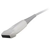
Датчики для аппарата SonoAce R3
Конвексные датчики
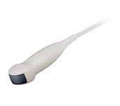
Конвексный датчик 2-4 МГц (микроконвексный)
Кардиология, абдоминальные исследования (печень, желчный пузырь, поджелудочная железа, селезенка, глубокие сосуды), почки.
Биопсийный набор: нет.
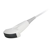
Конвексный датчик 2-8 МГц
Акушерские исследования (плод, сердце плода), гинекология (матка, яичники), абдоминальные исследования (печень, желчный пузырь, поджелудочная железа, селезенка, глубокие сосуды), почки.
Биопсийный набор: есть.
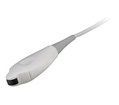
Конвексный датчик 4-9 МГц (неонатальный)
Неонатология и педиатрия: абдоминальные исследования, почки, сердце, глубокие сосуды, мозг.
Биопсийный набор: нет.
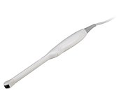
Конвексный датчик 4-9 МГц (ректо-вагинальный)
Акушерские исследования (ранние сроки), гинекология (матка, яичники), урология (предстательная железа), исследования прямой кишки.
Биопсийный набор: есть.
Линейные датчики
Линейный датчик 5-12/40 МГц
Поверхностные структуры (щитовидная железа, молочная железа, лимфоузлы), мускулоскелетные исследования (суставы, мышцы, подкожные структуры), периферические сосуды.
Биопсийный набор: есть.
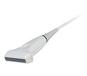
Линейный датчик 5-12/60 МГц
Поверхностные структуры (щитовидная железа, молочная железа, лимфоузлы), мускулоскелетные исследования (суставы, мышцы, подкожные структуры), периферические сосуды.
Биопсийный набор: есть.
Внимание! Копирование или частичная перепечатка материалов проспекта сканера «SonoAce R3» на русском языке и размещение в интернет без согласия владельца (ЗАО «Медиэйс») запрещена, запрос на копирование материала можно отправить здесь.
Посмотреть инструкция для Samsung SonoAce R3 бесплатно. Руководство относится к категории без категории, 1 человек(а) дали ему среднюю оценку 8.2. Руководство доступно на следующих языках: английский. У вас есть вопрос о Samsung SonoAce R3 или вам нужна помощь? Задайте свой вопрос здесь
Не можете найти ответ на свой вопрос в руководстве? Вы можете найти ответ на свой вопрос ниже, в разделе часто задаваемых вопросов о Samsung SonoAce R3.
Инструкция Samsung SonoAce R3 доступно в русский?
Не нашли свой вопрос? Задайте свой вопрос здесь
![]()
ENGLISH
Document No. CSD-SMESAR3
Revision 01
Copyright SAMSUNG MEDISON Co., LTD.
Safety Requirements
Classifications:
—Type of protection against electrical shock: Class I
—Degree of protection against electrical shock (Patient connection):Type BF equipment
—Degree of protection against harmful ingress of water: Ordinary equipment
—Degree of safety of application in the presence of a flammable anesthetic material with air or with oxygen or nitrous oxide: Equipment not suitable for use in the presence of a flammable anesthetic mixture with air or with oxygen or nitrous oxide.
—Mode of operation: Continuous operation
Electromechanical safety standards met:
—IEC/EN 60601-1 Medical Electrical Equipment, Part 1General Requirements for Safety.
—IEC/EN 60601-1-1 Safety requirements for medical electrical systems.
—IEC/EN 60601-1-2 Electromagnetic compatibility -Requirements and tests.
—IEC/EN 60601-2-37 Particular requirements for the safety of ultrasonic medical diagnostic and monitoring equipment.
—IEC 61157 Declaration of acoustic output parameters.
—ISO 10993-1 Biological evaluation of medical devices.
—UL 60601-1 Medical Electrical Equipment, Part 1 General Requirements for Safety.
—CSA 22.2, 601.1 Medical Electrical Equipment, Part 1 General Requirements for Safety.

Declarations:
This is CSA symbol for Canada and United States of America
This is manufacturer’s declaration of product compliance 0123 with applicable EEC directive(s) and the European notified
body.
This is manufacturer’s declaration of product compliance with applicable EEC directive(s).
This is GMP symbol for Good Manufacturing Practice of
Korea quality system regulation.

READ THIS FIRST
Before asking for the product to be repaired, read this service manual thoroughly, learn how to troubleshoot, and make sure you understand the precautions fully.
The repair of the system and the replacement of parts must be carried out by an authorized dealer or the customer service department of SAMSUNG MEDISON Co., Ltd.
The company is shall not be held liable for any injury and damage caused by not following this warning.
For safe use of this product, you should read ‘Chapter 2. Safety’ in this manual, prior to starting to
useing this system.
DANGER˙ ˙ ˙ ˙ ˙ ˙
Describes precautions necessary to prevent user hazards of great urgency. Ignoring a DANGER warning will risk life-threatening injury.
˙ ˙ ˙ ˙˙˙ ˙
WARNING
Used to indicate the presence of a hazard that can cause serious personal injury, or substantial property damage.
˙ ˙ ˙ ˙˙˙ ˙
CAUTION
Indicates the presence of a hazard that can cause equipment damage.
NOTE˙ ˙ ˙ ˙
A piece of information useful for installing, operating and maintaining a system. Not related to any hazard.

Contents
|
Chapter 1. General Information |
|||
|
1.1 |
Overview |
…………………………………………………………………………………………. |
1-1 |
|
1.2 |
FeaturesandAdvantagesofSonoAceR3………………………………………….. |
1-2 |
|
|
1.3 |
ProductConfiguration………………………………………………………………………… |
1-3 |
|
|
1.3.1 |
Console…………………………………………………………………………….. |
1-3 |
|
|
1.3.2 |
LCDMonitor……………………………………………………………………… |
1-4 |
|
|
1.3.3 |
ControlPanel…………………………………………………………………….. |
1-5 |
|
|
1.3.4 |
Probe……………………………………………………………………………….. |
1-5 |
|
|
1.4 |
Specifications…………………………………………………………………………………….. |
1-6 |
|
Chapter 2. Safety |
|||
|
2.1 |
Overview |
…………………………………………………………………………………………. |
2-1 |
|
2.2 |
Safety-RelatedInformation…………………………………………………………………. |
2-2 |
|
|
2.2.1 |
SafetySymbols…………………………………………………………………. |
2-2 |
|
|
2.2.2 |
LABEL………………………………………………………………………………. |
2-3 |
|
|
2.3 |
ElectricalSafety…………………………………………………………………………………. |
2-4 |
|
|
2.3.1 |
Prevention ElectricShock………………………………………………….. |
2-4 |
|
|
2.3.2 |
ESD………………………………………………………………………………….. |
2-4 |
|
|
2.3.3 |
EMI…………………………………………………………………………………… |
2-5 |
|
|
2.3.4 |
EMC…………………………………………………………………………………. |
2-5 |
|
|
2.4 |
MechanicalSafety……………………………………………………………………………… |
2-11 |
|
|
2.4.1 |
MovingEquipment…………………………………………………………….. |
2-11 |
|
|
2.4.2 |
SafetyNote……………………………………………………………………….. |
2-11 |
|
|
2.5 |
BiologicalSafety………………………………………………………………………………… |
2-12 |
|
|
2.5.1 |
ALARAPrinciple……………………………………………………………….. |
2-12 |
|
|
2.6 |
EnvironmentalProtection…………………………………………………………………… |
2-24 |

Contents
|
Chapter 3. Installing the Product |
|||
|
3.1 |
Overview |
…………………………………………………………………………………………. |
3-1 |
|
3.2 |
Transportation…………………………………………………………………………………… |
3-3 |
|
|
3.2.1 |
PrecautionsforTransportation……………………………………………. |
3-3 |
|
|
3.2.2 |
TemperatureandHumidity………………………………………………… |
3-3 |
|
|
3.3 |
Unpacking |
…………………………………………………………………………………………. |
3-4 |
|
3.3.1 |
UnpackingtheBox…………………………………………………………….. |
3-4 |
|
|
3.3.2 |
CheckingPackagecontents………………………………………………. |
3-5 |
|
|
3.4 |
PrecautionsforInstallation…………………………………………………………………. |
3-6 |
|
|
3.4.1 |
Precautions……………………………………………………………………….. |
3-6 |
|
|
3.5 |
InstallationsProcedure………………………………………………………………………. |
3-7 |
|
|
3.5.1 |
InstallationSafety………………………………………………………………. |
3-7 |
|
|
3.5.2 |
ConnectingthePowerCord……………………………………………….. |
3-8 |
|
|
3.5.3 |
ConnectingtheNetworkCable…………………………………………… |
3-9 |
|
|
3.5.4 |
ConnectingtheProbe………………………………………………………… |
3-9 |
|
|
3.6 |
StartingtheProduct…………………………………………………………………………… |
3-10 |
|
|
3.7 |
ShuttingdowntheProduct…………………………………………………………………. |
3-11 |
|
|
3.8 |
ConnectingthePeripherals………………………………………………………………… |
3-12 |
|
|
3.8.1 |
ExternalPeripherals………………………………………………………….. |
3-12 |
|
|
3.9 |
SystemSetting………………………………………………………………………………….. |
3-14 |
|
|
3.9.1 |
General SystemSetup………………………………………………………. |
3-14 |
|
|
3.9.2 |
DisplaySetup……………………………………………………………………. |
3-16 |
|
|
3.9.3 |
Misc………………………………………………………………………………….. |
3-18 |
|
|
3.10 |
MeasureSetting………………………………………………………………………………… |
3-19 |
|
|
3.10.1 |
General…………………………………………………………………………….. |
3-19 |
|
|
3.10.2 |
Doppler…………………………………………………………………………….. |
3-20 |
|
|
3.10.3 |
Report………………………………………………………………………………. |
3-21 |
|
|
3.10.4 |
OB……………………………………………………………………………………. |
3-22 |
|
|
3.10.5 |
FetalEcho………………………………………………………………………… |
3-25 |
|
|
3.10.6 |
Cardiac……………………………………………………………………………… |
3-26 |
|
|
3.10.7 |
Urology……………………………………………………………………………… |
3-26 |
|
|
3.10.8 |
Vascular……………………………………………………………………………. |
3-27 |
|
|
3.11 |
SettingDICOM(Optional)…………………………………………………………………. |
3-28 |
|
|
3.11.1 |
SettingDICOMInformation………………………………………………… |
3-28 |
|
|
3.11.2 |
NetworkSetup…………………………………………………………………… |
3-29 |
|
|
3.11.3 |
AddingorChangingtheDICOMServer……………………………… |
3-29 |
|
|
3.11.4 |
EditingtheDICOMServer………………………………………………….. |
3-32 |
|
|
3.11.5 |
DeletingDICOMServer……………………………………………………… |
3-32 |

|
3.11.6 |
TestingDICOMServer………………………………………………………. |
3-32 |
|
|
3.11.7 |
DICOMLog………………………………………………………………………. |
3-32 |
|
|
3.12 |
SettingOption……………………………………………………………………………………. |
3-34 |
|
|
3.13 |
SettingPeripheralDevices…………………………………………………………………. |
3-35 |
|
|
3.13.1 |
VideoOutType…………………………………………………………………. |
3-35 |
|
|
3.13.2 |
FootSwitch……………………………………………………………………….. |
3-35 |
|
|
3.13.3 |
Printer1……………………………………………………………………………. |
3-35 |
|
|
3.13.4 |
Printer2……………………………………………………………………………. |
3-35 |
|
|
3.14 |
Information………………………………………………………………………………………… |
3-36 |

Contents
|
Chapter 4. Checking the Product |
|||
|
4.1 |
Overview |
……………………………………………………………………………………….. |
4-1 |
|
4.2 |
StartingtheProduct…………………………………………………………………………… |
4-2 |
|
|
4.3 |
Monitor |
…………………………………………………………………………………………. |
4-3 |
|
4.3.1 |
MonitorDisplay…………………………………………………………………. |
4-3 |
|
|
4.4 |
ControlPanel…………………………………………………………………………………….. |
4-5 |
|
|
4.4.1 |
DetailControlPanel…………………………………………………………… |
4-6 |
|
|
4.4.2 |
SoftMenu…………………………………………………………………………. |
4-8 |
|
|
4.4.3 |
Keyboards………………………………………………………………………… |
4-9 |
|
|
4.5 |
CheckingthePerformance ……………………………………………………………….. |
4-11 |
|
|
4.5.1 |
BasicCheck……………………………………………………………………… |
4-11 |
|
|
4.5.2 |
DetailCheck……………………………………………………………………… |
4-12 |

Contents
|
5 |
|||
|
5.1 |
5-1 |
||
|
5.2 |
SystemBlockDiagram………………………………………………………………………. |
5-3 |
|
|
5.3 |
EKO7 ……………………………………………………………………………. |
5-4 |
|
|
5.3.1 |
………………………………………………………………………………….. |
5-4 |
|
|
5.3.2 |
UltrasoundSystemPart…………………………………………………….. |
5-4 |
|
|
5.3.3 |
PCPart…………………………………………………………………………….. |
5-5 |
|
|
5.3.4 |
UserInterfacePart…………………………………………………………….. |
5-5 |
|
|
5.3.5 |
ACtoDC PowerModule……………………………………………………. |
5-5 |
|
|
5.4 |
PSA |
5-6 |
|
|
5.5 |
BeamformerBoard…………………………………………………………………………….. |
5-8 |
5.6CWBoard5-11
|
5.7 |
BackEndBoard………………………………………………………………………………… |
5-14 |
5.8PCIBoard5-18
5.9DVIBoard5-19
5.10VGACard5-21
|
5.11 |
VCRINBoard…………………………………………………………………………………….. |
5-22 |
|
5.12 |
PCMotherBoard………………………………………………………………………………. |
5-23 |
|
5.13 |
SoftwareDSC……………………………………………………………………………………. |
5-24 |
|
5.14 |
LCDIFBoard…………………………………………………………………………………….. |
5-26 |
|
5.15 |
RearBoard……………………………………………………………………………………….. |
5-27 |
|
5.16 |
ControlPanel…………………………………………………………………………………….. |
5-28 |
|
5.17 |
PowerSupply……………………………………………………………………………………. |
5-30 |
![]()
Contents
|
Chapter 6. Basic Maintenance |
|||
|
6.1 |
Overview |
…………………………………………………………………………………………. |
6-1 |
|
6.2 |
SystemInformation……………………………………………………………………………. |
6-2 |
|
|
6.3 |
AdminMode……………………………………………………………………………………… |
6-3 |
|
|
6.3.1 |
Entering AdminMode………………………………………………………… |
6-3 |
|
|
6.3.2 |
AdminModeFunctions………………………………………………………. |
6-4 |
|
|
6.4 |
Upgrade |
……………………………………………………………………………………….. |
6-6 |
|
6.4.1 |
SoftwareUpgrade……………………………………………………………… |
6-6 |
|
|
6.4.2 |
HardwareUpgrade……………………………………………………………. |
6-9 |
|
|
6.5 |
Backup&Restore……………………………………………………………………………… |
6-10 |
|
|
6.5.1 |
BackupUserSetting………………………………………………………….. |
6-10 |
|
|
6.5.2 |
RestoreUserSetting…………………………………………………………. |
6-12 |
|
|
6.6 |
AddingandDeletingOptions………………………………………………………………. |
6-14 |
|
|
6.6.1 |
Optiontype……………………………………………………………………….. |
6-14 |
|
|
6.6.2 |
RegisteringOption…………………………………………………………….. |
6-14 |
|
|
6.7 |
ControlPanel…………………………………………………………………………………….. |
6-16 |

Contents
|
Chapter 7. Troubleshooting |
|||
|
7.1 |
Overview |
…………………………………………………………………………………………. |
7-1 |
|
7.2 |
Power |
…………………………………………………………………………………………. |
7-2 |
|
7.2.1 |
PowerFailure……………………………………………………………………. |
7-2 |
|
|
7.2.2 |
Powercannotturnedoff…………………………………………………….. |
7-2 |
|
|
7.2.3 |
Powerisautomaticallyturnedoff………………………………………… |
7-2 |
|
|
7.3 |
Monitro |
…………………………………………………………………………………………. |
7-3 |
|
7.3.1 |
BlankScreen…………………………………………………………………….. |
7-3 |
|
|
7.3.2 |
ScreenColorAbnomal………………………………………………………. |
7-3 |
|
|
7.4 |
ErrorMessages…………………………………………………………………………………. |
7-4 |
|
|
7.4.1 |
Systemhangsafteranerrorduringbooting…………………………. |
7-4 |
|
|
7.4.2 |
Systemworkseveniferroroccurred…………………………………… |
7-4 |
|
|
7.5 |
Image |
…………………………………………………………………………………………. |
7-5 |
|
7.5.1 NoBWImageEcho&NoBWModeImageFormat……………………. |
7-5 |
||
|
7.5.2 NoiseLinkRainovertheBWModeImage(Noise)……………………… |
7-5 |
||
|
7.5.3 PW&ColorDopplerModeTrouble…………………………………………… |
7-5 |

Contents
|
Chapter 8. Disassembly and Reassembly |
|||
|
8.1 |
Overview |
…………………………………………………………………………………………. |
8-1 |
|
8.2 |
Disassembly and Reassembly of the Body Cover ……………………………….. |
8-3 |
|
|
8.2.1 |
Preparations……………………………………………………………………… |
8-3 |
|
|
8.2.2 |
BodyRear&MiddleCover………………………………………………… |
8-3 |
|
|
8.2.3 |
Disassembly of the Main Part and LCD/Control Panel…………. |
8-4 |
|
|
8.3 |
Disassembly and Reassembly of the Main System Part………………………. |
8-5 |
|
|
8.3.1 |
Preparations……………………………………………………………………… |
8-5 |
|
|
8.3.2 |
Power&HDD&SideFan………………………………………………….. |
8-5 |
|
|
8.3.3 |
PSA&Rear&RearFan&Handle……………………………………… |
8-6 |
|
|
8.3.4 |
LCD&Inverter&USBBoard……………………………………………… |
8-7 |
|
|
8.4 |
Disassembly and Reassembly of the Control Panel …………………………….. |
8-8 |
|
|
8.4.1 |
Preparations……………………………………………………………………… |
8-8 |
|
|
8.4.2 |
Disassembly Control Panel and LCD………………………………….. |
8-8 |
|
|
8.4.3 |
ControlPanel…………………………………………………………………….. |
8-9 |

Contents
|
Chapter 9. Probe |
|||
|
9.1 |
Overview |
…………………………………………………………………………………………. |
9-1 |
|
9.2 |
ProbeList |
…………………………………………………………………………………………. |
9-2 |
|
9.3 |
ThermalIndex(TITable)……………………………………………………………………. |
9-5 |
|
|
9.4 |
UltrasoundTransmissionGel……………………………………………………………… |
9-6 |
|
|
9.5 |
Sheaths |
…………………………………………………………………………………………. |
9-7 |
|
9.6 |
ProbePrecautions……………………………………………………………………………… |
9-9 |
|
|
Chapter 10. User Maintenance |
|||
|
10.1 |
Overview |
…………………………………………………………………………………………. |
10-1 |
|
10.2 |
SystemMaintenance…………………………………………………………………………. |
10-2 |
|
|
10.2.1 |
InstallationMaintenance…………………………………………………….. |
10-2 |
|
|
10.2.2 |
CleaningandDisinfections…………………………………………………. |
10-2 |
|
|
10.2.3 |
FuseReplacement……………………………………………………………. |
10-3 |
|
|
10.2.4 |
AccuracyCheck………………………………………………………………… |
10-4 |
|
|
10.3 |
AdministrationofInformation………………………………………………………………. |
10-5 |
|
|
10.3.1 |
UserSettingBack-up…………………………………………………………. |
10-5 |
|
|
10.3.2 |
PatientInformationBack-up……………………………………………….. |
10-5 |
|
|
10.3.3 |
Software……………………………………………………………………………. |
10-5 |
|
|
Chapter 11. Service Part List |
|||
|
11.1 |
Overview |
…………………………………………………………………………………………. |
11-1 |
|
11.2 |
BodyCover……………………………………………………………………………………….. |
11-2 |
|
|
11.3 |
UltrasoundSystemPart ……………………………………………………………………. |
11-4 |
|
|
11.4 |
LCDPart |
…………………………………………………………………………………………. |
11-5 |
|
11.5 |
PCPart |
…………………………………………………………………………………………. |
11-6 |
|
11.6 |
PowerPart………………………………………………………………………………………… |
11-8 |
|
|
11.7 |
UserInterfacePart…………………………………………………………………………….. |
11-9 |
|
|
11.8 |
ETCPart |
……………………………………………………………………………………. |
11-10 |
|
11.9 |
Options |
……………………………………………………………………………………… |
11-11 |
|
11.10 |
Probes |
……………………………………………………………………………………… |
11-12 |

Chapter 1. General Information
1.1Overview
Chapter 1 contains the information necessary to plan the Troubleshooting of SonoAceR3.
The SonoAceR3 is a high-resolution color ultrasound scanner with high penetration and a variety of measurement functions.
Contents
|
1.1 |
Overview |
………………………………………………………………………………………. |
1-1 |
|
1.2 |
Features ………………………………………..and Advantages of SonoAceR3 |
1-2 |
|
|
1.3 |
Product Configuration ……………………………………………………………………. |
1-3 |
|
|
1.3.1 ………………………………………………………………………… |
Console |
1-3 |
|
|
1.3.2 …………………………………………………………………. |
LCD Monitor |
1-4 |
|
|
1.3.3 ………………………………………………………………… |
Control Panel |
1-5 |
|
|
1.3.4 ………………………………………………………………………….. |
Probes |
1-5 |
|
|
1.4 |
Specifications………………………………………………………………………………… |
1-6 |
Chapter 1. General Information 1-1

1.2Features and Advantages of SonoAceR3
zHigh-end Digital Beamforming : The SonoAceR3 utilizes the newly developed Digital Beam forming technology.
zA variety of applications : The SonoAceR3 is optimized for use in a variety of ultrasound departments, cardiac, vascular, abdomen, Obsterics, Urology, Gynecology.
zVarious diagnostic Modes : 2D Mode, M Mode, Color Doppler Mode, Power Doppler Mode, PW Spectral Doppler Mode, etc.
zMeasurement and Report Functions : Besides the basic distance, area, circumference and volume measurement functions, the SonoAceR3 also provides application-specific measurement functions. The report function collates measurement data.
zReview of Scanned Images : The SonoAceR3 displays Cine images of 512 frames and loop images of 4096 lines.
zSonoViewTM : This is a total ultrasound image management system, which allows a user to archive, view and exchange documents.
zDigital Imaging and Communication in Medicine (DICOM) Function : This is used to archive, transmit and print DICOM images through a network.
zPeripheral/Accessory Connection : A variety of peripheral devices including VCRs and printers can be easily connected to the SonoAceR3.
Chapter 1. General Information 1-2
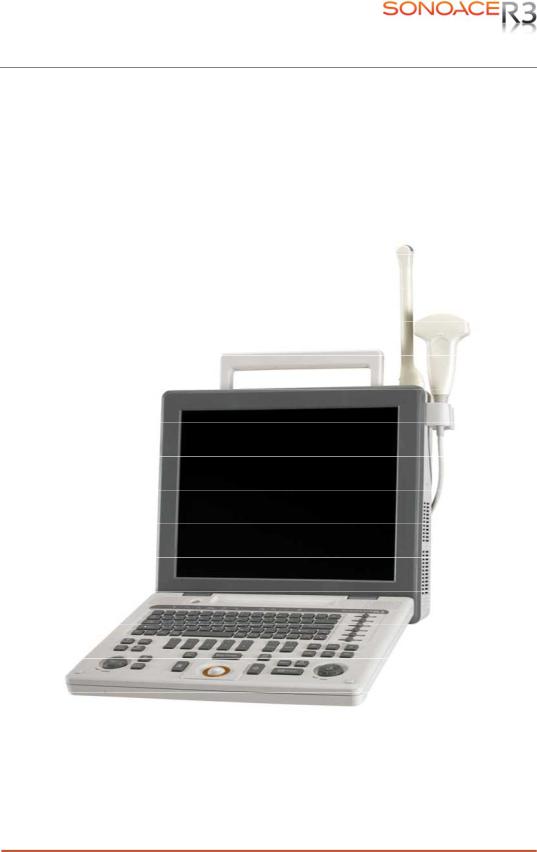
1.3Product Configuration
This Product consists of the monitor, the control panel, the console and, the probes and the cart(optional).
1.3.2Console
The console consists of two parts – the inner unit and the outer unit.
The interior of the console mainly contains devices that produce ultrasound images. The outside of the console consists of various connection ports and handles.
Handle 
 LCD Monitor
 Control Panel
[Figure 1-1] Console of SonoAce R3
Chapter 1. General Information 1-3

Probe Connector
[Figure 1-2] Front and Back of SonoAce R3
1.3.2LCD Monitor
The monitor of this system is a color VGA monitor, which displays ultrasound images and additional information. This monitor is connected to the main body through a central pivot, allowing it to be tilted to the optimal viewing angle.
[Figure 1-3] LCD Monitor
Chapter 1. General Information 1-4

1.3.3Control Panel
The control panel can be used for controlling the system.
Alpha-Numeric
Button
Dial Button
Track Ball 
Slide Volume
[Figure 1-4] Control Panel
1.3.4Probe
Probes are devices that generate ultrasound waves and process reflected wave data for the purpose of image formation.
NOT˙ ˙ ˙E˙
For more information, refer to ‘Chapter 9. Probes’.
Chapter 1. General Information 1-5
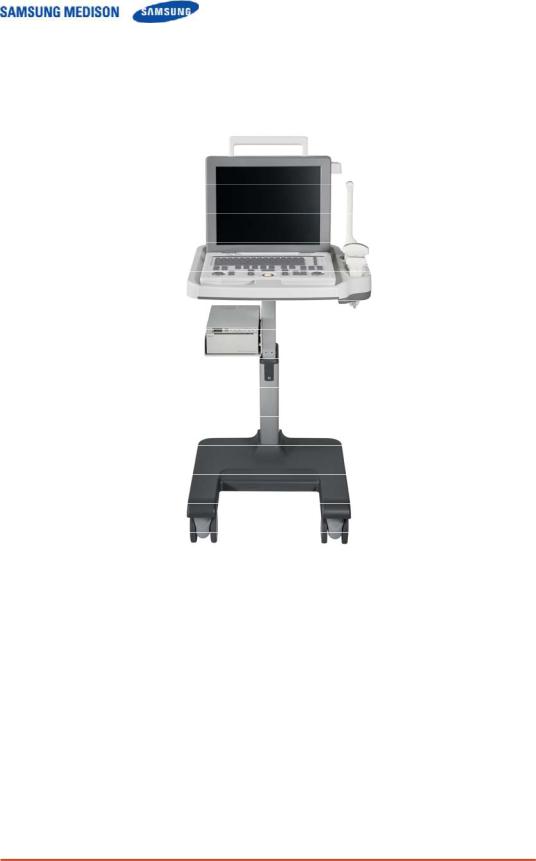
1.3.5SonoAceR3 Cart (Optional)
The SonoAce R3 System can be placed on a cart during use or for transport. For more information on installing and using the SonoAce R3, please refer to the installation guide that comes with it.
[Figure 1-5] SonoAce R3 Cart
Chapter 1. General Information 1-6
![]()
1.4Specifications
|
Height: 375mm (with handle) |
|||||
|
Physical Dimensions |
Width: 402mm (with probe holder) |
||||
|
Depth: 188mm(with control panel) |
|||||
|
Weight: More than 8.7kg |
|||||
|
2D real-time |
|||||
|
Dual 2D real-time |
|||||
|
2D/M-mode |
|||||
|
Imaging modes |
Power Doppler |
||||
|
Color Doppler for Option |
|||||
|
Pulsed-wave Doppler for Option |
|||||
|
3D-mode (Freehand) for Option |
|||||
|
Simultaneous |
|||||
|
Gray Scale |
256 (8 bits) |
||||
|
Dynamic transmit focusing, maximum of eight points (four points |
|||||
|
Focusing |
simultaneously selectable) |
||||
|
Digital dynamic receive focusing (continuous) |
|||||
|
Curved Linear Array : C2-4/20, CN2-8, CN4-9 |
|||||
|
Probes |
Linear Array : L5-12/60, LN5-12/40 |
||||
|
Endocavity Curved Linear Array : EC4-9 |
|||||
|
Probe connections |
One probe connectors |
||||
|
Two probe connectors for option |
|||||
|
Monitor |
15 inch LCD monitor |
||||
|
USB 3ports |
|||||
|
LAN(10/100 BASE-T) |
|||||
|
Rear Panel |
DVI Output |
||||
|
Input/Output |
BW Printer remote control |
||||
|
Connections |
BW Output |
||||
|
S-VHS Output |
|||||
|
Sound Output |
|||||
|
Maximum 512 frames for CINE memory |
|||||
|
Image Storage |
Maximum 4096 Lines for LOOP memory |
||||
|
Image filing system |
|||||
|
Gynecology, Abdomen, OB, Renal, Urology, Vascular, Small |
|||||
|
Application |
Part, Fetal Heart, Breast, Musculoskeletal, Pediatric, Neonatal, |
||||
|
Cardiac |
|||||
|
Electrical Parameters |
100-120V/200-240V, 250VA, 50/60Hz |
||||
|
Chapter 1. General Information 1-7 |

|
Obssterics |
|||||
|
Gynecology |
|||||
|
Automatic Calculation |
Cardiology |
||||
|
Fetal Echo |
|||||
|
and Quantification |
|||||
|
Vascular |
|||||
|
Urology |
|||||
|
*Refer the Chapter 5 for additional information |
|||||
|
TGC control |
|||||
|
Mode-independent gain control |
|||||
|
Acoustic power control (adjustable) |
|||||
|
Signal processing |
Dynamic aperture |
||||
|
Dynamic apodization |
|||||
|
(Pre-processing) |
|||||
|
Dynamic range control (adjustable) |
|||||
|
Image view area control |
|||||
|
M-mode sweep speed control |
|||||
|
HD zoom |
|||||
|
Frame average |
|||||
|
Signal processing |
Gamma-scale windowing |
||||
|
(Post-processing) |
Image orientation (left/right and up/down, rotation) |
||||
|
White on black/black on white |
|||||
|
Trackball operation of multiple cursors |
|||||
|
2D mode: Linear measurements and area measurements |
|||||
|
Measurement |
using elliptical approximation or trace |
||||
|
M mode: Continuous readout of distance, time, and slope rate |
|||||
|
Doppler mode: Velocity and trace |
|||||
|
Black-and white printer |
|||||
|
Color printer |
|||||
|
Auxiliary |
VCR |
||||
|
Monitor |
|||||
|
Foot switch |
|||||
|
User Interface |
English, German, French, Spanish, Italian, Russian, Chinese |
||||
|
Pressure Limits |
Operating: 700hPa to 1060hPa |
||||
|
Storage: 700hPa to 1060hPa |
|||||
|
Humidity Limits |
Operating: 30% to 75% |
||||
|
Storage & Shipping: 20% to 90% |
|||||
|
Temperature Limits |
Operating: 10 OC ~ 35OC |
||||
|
Storage & Shipping: -25OC ~ 60OC |
|||||
Chapter 1. General Information 1-8

Chapter 2. Safety
2.1Overview
Chapter 2 contains the information necessary to Safety
Please read this chapter before using the SAMSUNG MEDISON ultrasound system. It is relevant to the ultrasound system, the probes, the recording devices, and any of the optional equipment.
SonoAce R3 is intended for use by, or by the order of, and under the supervision of, a licensed physician who is qualified for direct use of the medical device.
Contents
|
2.1 |
Overview |
………………………………………………………………………………………. |
2-1 |
|
2.2 |
Safety –Related …………………………………………………………..Information |
2-2 |
|
|
2.2.1 …………………………………………………………….. |
Safety Symbols |
2-2 |
|
|
2.2.2 ………………………………………………………………………….. |
LABEL |
2-3 |
|
|
2.3 |
Electrical ……………………………………………………………………………..Safety |
2-4 |
|
|
2.3.1 ……………………………………………… |
Prevention Electric Shock |
2-4 |
|
|
2.3.2 ……………………………………………………………………………… |
ESD |
2-4 |
|
|
2.3.3 ………………………………………………………………………………. |
EMI |
2-5 |
|
|
2.3.4 …………………………………………………………………………….. |
EMC |
2-5 |
|
|
2.4 |
Mechanical ………………………………………………………………………..Safety |
2-11 |
|
|
2.4.1 ………………………………………………………. |
Moving Equipment |
2-11 |
|
|
2.4.2 …………………………………………………………………. |
Safety Note |
2-11 |
|
|
2.5 |
Biological ………………………………………………………………………….Safety |
2-12 |
|
|
2.5.1 …………………………………………………………. |
ALARA Principle |
2-12 |
|
|
2.6 |
Environmental ……………………………………………………………..Protection |
2-24 |
Chapter 2. Safety 2-1
2.2Safety – Related Information
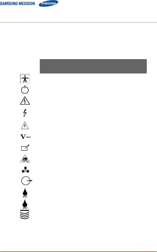
2.2.1Safety Symbols
The International Electro Technical Commission (IEC) has established a set of
symbols for medical electronic equipment, which classifies a connection or warn of potential hazards. The classifications and symbols are shown below.
|
Symbols |
Description |
|
Isolated patient connection (Type BF applied part). |
|
|
Power switch (Supplies/cuts the power for product). |
|
|
Indicates a caution for risk of electric shock. |
|
|
Indicates dangerous voltages over 1000V AC or over |
|
|
1500V DC. |
|
|
Warning, Caution |
|
|
AC (alternating current) voltage source |
|
|
Print remote output |
|
|
Electrostatic discharge |
|
|
Network port |
|
|
Output port ( DVI, RGB, B/W, S-VHS, SOUND ) |
|
|
Protection against the effects of immersion. |
|
|
Protection against dripping water. |
|
|
Probe connector |
|
Chapter 2. Safety 2-2
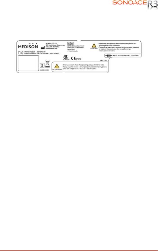
2.2.2LABEL
To protect the system, you may see ‘Warning’ or ‘Caution’ marked on the surface of the product
[Figure 2-1]Marked on the product
Chapter 2. Safety 2-3
2.3Electrical Safety
This equipment has been verified as a Class I device with Type BF applied parts.
2.3.1Prevention of Electric Shock
Additional equipment connected to medical electrical equipment must comply with the respective IEC or ISO standards (e.g. IEC 60950 for data processing equipment). Furthermore all configurations shall comply with the requirements for medical electrical systems (see IEC 60601-1-1 or clause 16 of the 3 Ed. of IEC 60601-1, respectively). Anybody connecting additional equipment to medical electrical equipment configures a medical system and is therefore responsible that the system complies with the requirements for medical electrical systems.
Attention is drawn to the fact that local laws take priority over the abovementioned requirements. If in doubt, consult your local representative or the technical service department.
˙ ˙ ˙ ˙˙˙ ˙
WARNING
zElectric shock may exist result if this system, including and all of its externally mounted recording and monitoring devices, is not properly grounded.
zDo not remove the covers on the system; hazardous voltages are present inside. Cabinet panels must be in place while the system is in use. All internal adjustments and replacements must be made by a qualified SAMSUNG MEDISON Customer Service Department.
zCheck the face, housing, and cable before use. Do not use, if the face is cracked, chipped, or torn, the housing is damaged, or if the cable is abraded.
zAlways disconnect the system from the wall outlet prior to cleaning the system.
zAll patient contact devices, such as probes and ECG leads, must be removed from the patient prior to application of a high voltage defibrillation pulse.
zThe use of flammable anesthetic gas or oxidizing gases (N20) should be avoided.
˙ ˙ ˙ ˙˙˙ ˙
CAUTION
zThe system has been designed for 100-120VAC and 200-240VAC; you should select the
inputOutlet voltage of monitor, printer and VCR. Prior to connecting an OEM power cord, verify that the voltage indicated on the power cord matches the voltage rating of the OEM device.
zAn isolation transformer protects the system from power surges. The isolation transformer continues to operate when the system is in standby.
zDo not immerse the cable in liquids. Cables are not waterproof.
zThe operator does not contact the parts (SIP/SOP) and the patient simultaneously.
Chapter 2. Safety 2-4
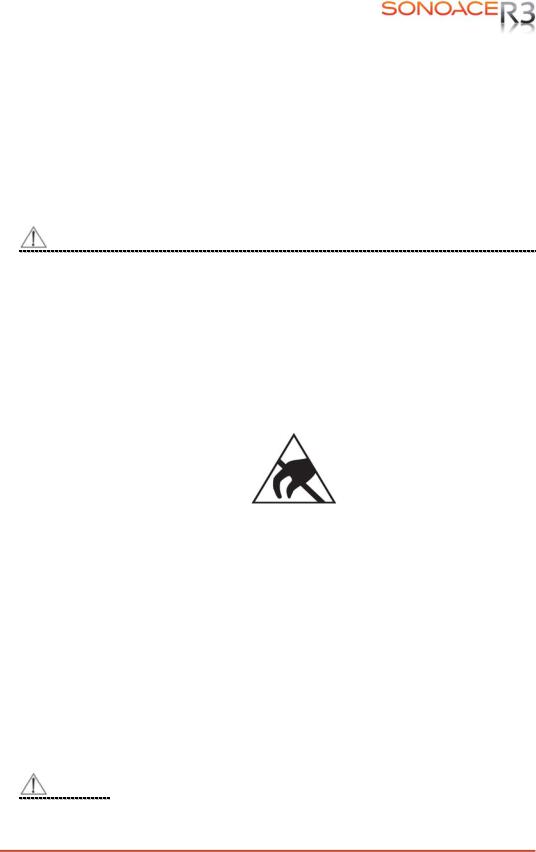
2.3.2ESD
Electrostatic discharge (ESD), commonly referred to as a static shock, is a naturally occurring phenomenon. ESD is most prevalent during conditions of low humidity, which can be caused by heating or air conditioning. During low humidity conditions, electrical charges naturally build up on individuals, creating static electricity. An ESD occurs when an individual with an electrical energy build-up comes in contact with conductive objects such as metal doorknobs, file cabinets, computer equipment, and even other individuals. The static shock or ESD is a discharge of the electrical energy build-up from a charged individual to a lesser or non-charged individual or object.
˙ ˙ ˙ ˙˙˙ ˙
CAUTION
zThe level of electrical energy discharged from a system user or patient to an ultrasound system can be significant enough to cause damage to the system or probes.
zAlways perform the pre-ESD preventive procedures before using connectors marked with the ESD warning label.
—Apply anti-static spray on carpets or linoleum.
—Use anti-static mats.
—Ground the product to the patient table or bed.
zIt is highly recommended that the user be given training on ESD-related warning symbols and preventive procedures.
[Figure 2-7] ESD symbol
2.3.3EMI
Although this system has been manufactured in compliance with existing EMI
(Electromagnetic Interference) requirements, use of this system in the presence of an electromagnetic field can cause momentary degradation of the ultrasound image.
If this occurs often, SAMSUNG MEDISON suggests a review of the environment in which the
system is being used, to identify possible sources of radiated emissions. These emissions could be from other electrical devices used within the same room or an adjacent room. Communication devices such as cellular phones and pagers can cause these emissions. The existence of radios, TVs, or microwave transmission equipment nearby can also cause interference.
˙ ˙ ˙ ˙˙˙ ˙
CAUTION
In cases where EMI is causing disturbances, it may be necessary to relocate this system.
Chapter 2. Safety 2-5

2.3.4EMC
The testing for EMC(Electromagnetic Compatibility) of this system has been performed according to the international standard for EMC with medical devices (IEC60601-1-2). This IEC standard was adopted in Europe as the European norm (EN60601-1-2).
2.3.4.1Guidance and manufacturer’s declaration — electromagnetic emission
This product is intended for use in the electromagnetic environment specified below. The customer or the user of this product should assure that it is used in such an environment.
|
Emission test |
Compliance |
Electromagnetic environment -guidance |
|||
|
RF Emission |
Group 1 |
The Ultrasound System uses RF energy only |
|||
|
(Radiation) |
for its internal function. Therefore, its RF |
||||
|
Class B |
|||||
|
CISPR 11 |
emissions are very low and are not likely to |
||||
|
RF Emission |
Group 1 |
cause any interference in nearby electronic |
|||
|
(Radiation) |
equipment. |
||||
|
Class B |
|||||
|
CISPR 11 |
The Ultrasound System is suitable for use in all |
||||
|
Harmonic Emission |
ClassA |
establishments, including domestic |
|||
|
IEC 61000-3-2 |
establishments and those directly connected to |
||||
|
Flicker Emission |
the public low-voltage power supply network |
||||
|
Complies |
that supplies building used for domestic |
||||
|
IEC 61000-3-3 |
|||||
|
purpose. |
|||||
2.3.4.2Approved Cables, Transducers and Accessories for EMC
1)Approved Cable for Electromagnetic Compliance
Cables connected to this product may affect its emissions; Use only the cable types and lengths listed below table.
|
Cable |
Type |
Length |
|
VGA |
Shielded |
Normal |
|
Parallel |
Shielded |
Normal |
|
RS232C |
Shielded |
Normal |
|
USB |
Shielded |
Normal |
|
LAN(RJ45) |
Twisted pair |
Any |
|
S-Video |
Shielded |
Normal |
|
Foot Switch |
Shielded |
2.5m |
|
B/W Printer |
Unshielded Coaxial |
Normal |
|
MIC |
Unshielded |
Any |
|
Printer Remote |
Unshielded |
Any |
|
Audio R.L |
Shielded |
Normal |
|
VHS |
Shielded |
Normal |
|
ECG AUX input |
Shielded |
< 3m |
Chapter 2. Safety 2-6

2) Approved Transducer for Electromagnetic Compliance
The probe listed in ‘Chapter 8. Probes’ when used with this product, have been tested to comply with the group1 class B emission as required by International Standard CISPR 11.
3) Approved Accessories for Electromagnetic Compliance
Accessories used with this product may effect its emissions
˙ ˙ ˙ ˙˙˙ ˙
CAUTION
When connecting other customer-supplied accessories to the system, such as a remote printer or VCR, it is the user’s responsibility to ensure the electromagnetic compatibility of the system. Use only CISPR 11 or CISPR 22, CLASS B compliant devices
˙ ˙ ˙ ˙˙˙ ˙
WARNING
The use of cables, transducers, and accessories other than those specified may result inincreased emission or decreased Immunity of the Ultrasound System.
|
Immunity test |
IEC 60601 |
Compliance level |
Electromagnetic environment — |
||||||||||
|
Test level |
guidance |
||||||||||||
|
Electrostatic |
±6KV Contact |
±6KV |
Contact |
Floors should be wood, concrete |
|||||||||
|
or ceramic tile. If floors are |
|||||||||||||
|
discharge (ESD) |
±8KV |
air |
±8KV |
air |
covered with synthetic material, |
||||||||
|
IEC 61000-4-2 |
the relative humidity should be at |
||||||||||||
|
least 30%. |
|||||||||||||
|
Electrical fast |
±2KV |
for power supply |
±2KV for power |
Mains power quality should be that |
|||||||||
|
of a typical commercial or hospital |
|||||||||||||
|
transient/burst |
lines |
supply lines |
|||||||||||
|
environment. |
|||||||||||||
|
±1KV for input/output |
±1KV for input/ |
||||||||||||
|
IEC 61000-4-4 |
lines |
output lines |
|||||||||||
|
Surge |
±1KV differential mode |
±1KV differential mode |
Mains power quality should be that |
||||||||||
|
IEC 61000-4-5 |
|||||||||||||
|
±2KV common mode |
±2KV common mode |
of a typical commercial or hospital |
|||||||||||
|
environment. |
|||||||||||||
|
Voltage dips, short |
<5% Uт |
<5% Uт |
Mains power quality should be that |
||||||||||
|
interruptions and |
(>95% dip in Uт) |
(>95% dip in Uт) |
of a typical commercial or hospital |
||||||||||
|
voltage variations |
for 0.5cycle |
for 0.5cycle |
environment. If the user of this |
||||||||||
|
on power supply |
product requires continued |
||||||||||||
|
input lines |
40% Uт |
40% Uт |
operation during power mains |
||||||||||
|
(60% dip in Uт ) |
(60% dip in Uт ) |
interruptions, it is recommended |
|||||||||||
|
IEC 61000-4-11 |
for 5 cycle |
for 5 cycle |
that this product be powered from |
||||||||||
|
an uninterruptible power supply or |
|||||||||||||
|
70% Uт |
70% Uт |
a battery. |
|||||||||||
|
(30% dip in Uт) |
(30% dip in Uт) |
||||||||||||
|
for 25 cycle |
for 25 cycle |
||||||||||||
|
<5% Uт |
<5% Uт |
||||||||||||
|
(<95% dip in Uт ) |
(<95% dip in Uт ) |
||||||||||||
|
for 5 s |
for 5 s |
Chapter 2. Safety 2-7
|
Power frequency |
Power frequency magnetic fields |
|||||
|
(50/60Hz) |
should be at levels characteristic |
|||||
|
magnetic field |
3 A/m |
3 A/m |
of a typical location in a typical |
|||
|
commercial or hospital |
||||||
|
IEC 61000-4-8 |
environment. |
|||||
|
NOTE Uт is the a.c. mains voltage prior to application of the test level. |
||||||
|
Conducted RF |
3 Vrms |
0.01V |
Portable and mobile RF communications |
|||
|
IEC 61000-4-6 |
150 kHz to 80MHz |
equipment should be used no closer to any part |
||||
|
of the Ultrasound System, including cables, |
||||||
|
than the recommended separation distance |
||||||
|
calculated from the equation applicable to the |
||||||
|
frequency of the transmitter. |
||||||
|
Recommended separation distance |
|
80MHz to 800MHZ |
|||
|
800MHz to 2.5GHz |
|||
|
Radiated RF |
3 V/m |
3 V/m |
Where P is the maximum output power rating of |
|
IEC 61000-4-3 |
80 MHz to 2.5GHz |
the transmitter in watts (W) according to the |
|
|
transmitter manufacturer and d is the |
|||
|
recommended separation distance in meters |
|||
|
(m). |
|||
|
Field strengths from fixed RF transmitters, as |
|||
|
deter-mined by an electromagnetic site survey, a |
|||
|
should be less than the compliance level in |
|||
|
each frequency range. b |
|||
|
Interference may occur in the vicinity of |
|||
|
equipment marked with the following symbol : |
NOTE 1) At 80MHz and 800MHz, the higher frequency range applies.
NOTE 2) These guidelines may not apply in all situations. Electromagnetic propagation is affected by absorption and reflection from structures, objects and people.
a Field strengths from fixed transmitters, such as base stations for radio (cellular/cordless) telephones and land mobile radios, amateur radio, AM and FM radio broadcast and TV broadcast cannot be predicted theoretically with accuracy. To assess the electromagnetic environment due to fixed RF transmitters, an electromagnetic site survey should be considered. If the measured field strength in the location in which the Ultrasound System is used exceeds the applicable RF compliance level above, the Ultrasound System should be observed to verify normal operation. If abnormal performance is observed, additional measures may be necessary, such as re-orienting or relocating the Ultrasound System or using a shielded location with a higher RF shielding effectiveness and filter attenuation.
b Over the frequency range 150kHz to 80MHz, field strengths should be less than [V1] V/m.
Chapter 2. Safety 2-8
![]()
2.3.4.3Recommended separation distances between portable and mobile RF communications equipment and the SonoAce R3
This product is intended for use in an electromagnetic environment in which radiated RF disturbances are controlled. The customer or the user of this product can help Prevent electromagnetic interference by maintaining a minimum distance between portable and mobile RF communications equipment (transmitters) and this product as recommended below, according to the maximum output power of the communications equipment.
|
Separation distance according to frequency of transmitter [m] |
||||
|
Rated maximum |
150kHz to 80MHz |
80MHz to 800MHz |
800MHz to |
|
|
2.5GHz |
||||
|
output power of |
||||
|
transmitter |
||||
|
[W] |
||||
|
V1=0.01Vrms |
E1=3 V/m |
E1=3V/m |
||
|
0.01 |
35.00 |
0.11 |
0.23 |
|
|
0.1 |
110.68 |
0.36 |
0.73 |
|
|
1 |
350.00 |
1.16 |
2.33 |
|
|
10 |
1106.80 |
3.68 |
7.37 |
|
|
100 |
3500.00 |
11.66 |
23.33 |
For transmitters rated at a maximum output power not listed above, the recommended separation distance d in meters (m) can be estimated using the equation applicable to the frequency of the transmitter, where p is the maximum output power rating of the transmitter in watts (W) according to the transmitter manufacturer.
NOTE 1) At 80MHz and 800MHz, the separation distance for the higher frequency range applies. NOTE2) These guidelines may not apply in all situations. Electromagnetic propagation is affected by absorption and reflection from structures, objects and people.
2.3.4.4Electromagnetic environment – guidance
The Ultrasound System must be used only in a shielded location with a minimum RF shielding effectiveness and, for each cable that enters the shielded location. Field strengths outside the shielded location from fixed RF transmitters, as determined by an electromagnetic site survey, should be less than 3V/m.
It is essential that the actual shielding effectiveness and filter attenuation of the shielded location be verified to assure that they meet the minimum specification.
˙ ˙ ˙ ˙˙˙ ˙
CAUTION
If the system is connected to other customer-supplied equipment, such as a local area network (LAN) or a remote printer, SAMSUNG MEDISON cannot guarantee
|
that the |
remote equipment will work correctly in the presence of |
|
Chapter 2. Safety 2-9 |

electromagnetic phenomena.
Chapter 2. Safety 2-10

2.3.4.5Avoiding Electromagnetic Interference
Typical interference on Ultrasound Imaging Systems varies depending on Electromagnetic phenomena. Please refer to following table.
|
Imaging Mode |
ESD1 |
RF2 |
Power Line3 |
|
Change of operating |
For sector imaging |
White dots, dashes, |
|
|
mode, system |
probes, white radial |
diagonal lines, or |
|
|
settings, or system |
bands or flashes in the |
diagonal lines near the |
|
|
reset. |
centerlines of the |
center of the image. |
|
|
2D or 3D |
Brief flashes in the |
image. |
|
|
displayed or recorded |
For linear imaging |
||
|
image. |
probes, white vertical |
||
|
bands, sometimes more |
|||
|
pronounced on the |
|||
|
sides of the image. |
|||
|
Increase in the image |
White dots, dashes, |
||
|
M |
background noise or |
diagonal lines, or |
|
|
white M mode lines. |
increase in image |
||
|
background noise |
|||
|
Color flashes, radial or |
Color flashes, dots, |
||
|
Color |
vertical bands, increase |
dashes, or changes in |
|
|
in background noise, or |
the color noise level. |
||
|
changes in color image. |
|||
|
Horizontal lines in the |
Vertical lines in the |
||
|
Doppler |
spectral display or |
spectral display, popping |
|
|
tones, abnormal noise |
type noise in the audio, |
||
|
in the audio, or both. |
or both. |
ESD caused by discharging of electric charge build-up on insulated surfaces or persons.
RF energy from RF transmitting equipment such as portable phones, hand-held radios, wireless devices, commercial radio and TV, and so on.
Conducted interference on powerlines or connected cables caused by other equipment, such as switching power supplies, electrical controls, and natural phenomena such as lightning.
A medical device can either generate or receive electromagnetic interference. The EMC standards describe tests for both emitted and received interference.
SAMSUNG MEDISON Ultrasound System does not generate interference in excess of the referenced standards.
An Ultrasound System is designed to receive signals at radio frequency and is therefore susceptible to interference generated by RF energy sources. Examples of other source of interference are medical device, information technology products, and radio and television transmission towers. Tracing the source of radiated interference can be a difficult task. Customers should consider the following in an attempt to locate the source:
Is the interference intermittent or constant?
zDoes the interference show up only with one transducers operating at the same frequency or with several transducer?
zDo two different transducer operating at the same frequency have the same problem?
zIs the interference present if the system is moved to a different location in the facility?
The answers to these questions will help determine if the problem reside with the system or the scanning environment. After you answer the question, contact your local SAMSUNG MEDISON customer service department.
Chapter 2. Safety 2-11

2.4Mechanical Safety
2.4.1Moving the Equipment
˙ ˙ ˙ ˙˙˙ ˙
CAUTION
zAlways turn the power off and disconnect the cables before moving the product.
 NOTE˙ ˙ ˙ ˙
zUse the handle on the product, and move the product slowly. You can also move the product by using the SonoAce R3 Cart (Optional).
2.4.2Safety Note
˙˙ ˙ ˙˙˙ ˙
CAUTION
zDo not press the control panel excessively.
zNever attempt to modify the product in any way.
zCheck the operational safety when using the product after a prolonged break in service.
zMake sure that other objects, such as metal pieces, do not enter the system.
zDo not block the ventilation slots.
zTo prevent damage to the power cord, be sure to grip the plug head – not the cord –when unplugging.
zExcessive bending or twisting of cables on patient-applied parts may cause failure or intermittent operation of the system.
zIncorrect cleaning or sterilization of a patient-applied part may cause permanent damage.
Please refer to “Chapter 8. Maintenance” for detailed information on protecting, cleaning and disinfecting the equipment.
Chapter 2. Safety 2-12

2.5Biological Safety
Verify the alignment of the Probe before use. See the “Chapter 9. Probes” section of this manual.
˙ ˙ ˙ ˙˙˙ ˙
WARNING
zUltrasound waves may have damaging effects on cells and, therefore, may be harmful to the patient. If there is no medical benefit, minimize the exposure time and maintain the ultrasound wave output level at low. Please refer to the ALARA principle.
zDo not use the system if an error message appears on the video display indicating that a hazardous condition exists. Note the error code, turn off the power to the system, and call your local SAMSUNG MEDISON Customer Service Department.
zDo not use a system that exhibits erratic or inconsistent updating. Discontinuities in the scanning sequence are indicative of a hardware failure that should be corrected before use.
zThe system limits the maximum contact temperature to 43 degree Celsius, and the ultrasonic waves output observes American FDA regulations.
2.5.1ALARA Principle
Guidance for the use of diagnostic ultrasound is defined by the “as low as reasonably achievable” (ALARA) principle. The decision as to what is reasonable has been left to the judgment and insight of qualified personnel. No set of rules can be formulated that would be sufficiently complete to dictate the correct response for every circumstance. By keeping ultrasound exposure as low as possible, while obtaining diagnostic images, users can minimize ultrasonic bio effects. Since the threshold for diagnostic ultrasound bio effects is undetermined, it is the sonographer’s responsibility to control the total energy transmitted into the patient. The sonographer must reconcile exposure time with diagnostic image quality. To ensure diagnostic image quality and limit exposure time, the ultrasound system provides controls that can be manipulated during the exam to optimize the results of the exam.
The ability of the user to abide by the ALARA principle is important. Advances in diagnostic ultrasound not only in the technology but also in the applications of the technology, have resulted in the need for more and better information to guide the user. The output indices are designed to provide that important information
There are a number of variables, which affect the way in which the output display indices can be used to implement the ALARA principle. These variables include mass, body size, location of the bone relative to the focal point, attenuation in the body, and ultrasound exposure time. Exposure time is an especially useful variable, because the user controls it. The ability to limit the index values over time support the ALARA principle..
Chapter 2. Safety 2-13

2.5.1.1Applying ALARA
The system-imaging mode used depends upon the information needed. 2D-mode and M-mode imaging provide anatomical information, while Doppler, Power, and Color imaging provide information about blood flow. Scanned modes, like 2Dmode, Power, or Color, disperse or scatter the ultrasonic energy over an area, while an unscanned mode, like M-mode or Doppler, concentrates ultrasonic energy. Understanding the nature of the imaging mode being used allows the sonographer to apply the ALARA principle with informed judgment. The probe frequency, system set-up values, scanning techniques, and operator experience aid the sonographer in meeting the definition of the ALARA principle.
The decision as to the amount of acoustic output is, in the final analysis, up to the system operator.
This decision must be based on the following factors: type of patient, type of exam, patient history, ease or difficulty of obtaining diagnostically useful information, and the potential localized heating of the patient due to probe surface temperatures. Prudent use of the system occurs when patient exposure is limited to the lowest index reading for the shortest amount of time necessary to achieve acceptable diagnostic results.
Although a high index reading does not mean that a bioeffect is actually occurring, a high index reading should be taken seriously. Every effort should be made to reduce the possible effects of a high index reading. Limiting exposure time is an effective way to accomplish this goal.
There are several system controls that the operator can use to adjust the image quality and limit the acoustic intensity. These controls are related to the techniques that an operator might use to implement ALARA. These controls can be divided into three categories: direct, indirect, and receiver control.
2.5.1.2Direct Controls
Application selection and the output intensity control directly affect acoustic intensity. There are different ranges of allowable intensity or output based on your selection. Selecting the correct range of acoustic intensity for the application is one of the first things required during any exam. For example, peripheral vascular intensity levels are not recommended for fetal exams. Some systems automatically select the proper range for a particular procedure, while others require manual selection. Ultimately, the user bears the responsibility for proper clinical use. The SAMSUNG MEDISON system provides both automatic and user-definable settings.
Output has direct impact on acoustic intensity. Once the application has been established, the output control can be used to increase or decrease the intensity output. The output control allows you to select intensity levels less than the defined maximum. Prudent use dictates that you select the lowest output intensity consistent with good image quality.
Chapter 2. Safety 2-14

2.5.1.3Indirect Controls
The indirect controls are those that have an indirect effect on acoustic intensity. These controls affect imaging mode, pulse repetition frequency, focus depth, pulse length, and probe selection.
The choice of imaging mode determines the nature of the ultrasound beam. 2Dmode is a scanning mode, Doppler is a stationary or unscanned mode. A stationary ultrasound beam concentrates energy on a single location. A moving or scanned ultrasound beam disperses the energy over a wide area and the beam is only concentrated on a given area for a fraction of the time necessary in unscanned mode.
Pulse repetition frequency or rate refers to the number of ultrasound bursts of energy over a specific period of time. The higher the pulse repetition frequency, the more pulses of energy in a given period of time. Several controls affect pulse repetition frequency: focal depth, display depth, sample volume depth, color sensitivity, number of focal zones, and sector width controls.
Focus of the ultrasound beam affects the image resolution. To maintain or increase resolution at a different focus requires a variation in output over the focal zone. This variation of output is a function of system optimization. Different exams require different focal depths. Setting the focus to the proper depth improves the resolution of the structure of interest.
Pulse length is the time during which the ultrasonic burst is turned on. The longer the pulse, the greater the time-average intensity value. The greater the timeaverage intensity, the greater the likelihood of temperature increase and cavitations. Pulse length or burst length or pulse duration is the output pulse duration in pulsed Doppler. Increasing the Doppler sample volume increases the pulse length.
Probe selection affects intensity indirectly. Tissue attenuation changes with frequency. The higher the probe operating frequency, the greater the attenuation of the ultrasonic energy. Higher probe operating frequencies require higher output intensity to scan at a deeper depth. To scan deeper at the same output intensity, a lower probe frequency is required. Using more gain and output beyond a point, without corresponding increases in image quality, can mean that a lower frequency probe is needed.
2.5.1.4Receiver Controls
Receiver controls are used by the operator to improve image quality. These controls have no effect on output. Receiver controls only affect how the ultrasound echo is received. These controls include gain, TGC, dynamic range, and image processing. The important thing to remember, relative to output, is that receiver controls should be optimized before increasing output. For example; before increasing output, optimize gain to improve image quality.
Chapter 2. Safety 2-15

2.5.1.5Additional Considerations
Ensure that scanning time is kept to a minimum, and ensure that only medically required scanning is performed. Never compromise quality by rushing through an exam. A poor exam will require a follow-up, which ultimately increases the time. Diagnostic ultrasound is an important tool in medicine, and, like any tool, should be used efficiently and effectively.
2.5.1.6Output Display Features
The system output display comprises two basic indices: a mechanical index and a thermal index.
The thermal index consists of the following indices: soft tissue (TIs) and bone (TIb). One of these three thermal indices will be displayed at all times. Which one depends upon the system preset or user choice, depending upon the application at hand.
The mechanical index is continuously displayed over the range of 0.0 to 1.9, in increments of 0.1.
The thermal index consists of the three indices, and only one of these is displayed at any one time.
Each probe application has a default selection that is appropriate for that combination. The TIb or TIs is continuously displayed over the range of 0.0 to maximum output, based on the probe and application, in increments of 0.1.
The application-specific nature of the default setting is also an important factor of index behavior.
A default setting is a system control state which is preset by the manufacturer or the operator.
The system has default index settings for the probe application. The default settings are invoked automatically by the ultrasound system when power is turned on, new patient data is entered into the system database, or a change in application takes place.
The decision as to which of the three thermal indices to display should be based on the following criteria:
Appropriate index for the application: TIs is used for imaging soft tissue; and TIb for a focus at or near bone.
Some factors might create artificially high or low thermal index readings e.g. presence of fluid or bone, or the flow of blood. A highly attenuating tissue path, for example, will cause the potential for local zone heating to be less than the thermal index displays.
Scanned modes versus unscanned modes of operation affect the thermal index. For scanned modes, heating tends to be near the surface; for unscanned modes, the potential for heating tends to be deeper in the focal zone.
Always limit ultrasound exposure time. Do not rush the exam. Ensure that the indices are kept to a minimum and that exposure time is limited without compromising diagnostic sensitivity.
Chapter 2. Safety 2-16

1) Mechanical Index (MI) Display
Mechanical bio effects are threshold phenomena that occur when a certain level of output is exceeded. The threshold level varies, however, with the type of tissue. The potential for mechanical bio effects varies with peak pressure and ultrasound frequency. The MI accounts for these two factors. The higher the MI value, the greater the likelihood of mechanical bio effects occurring but there is no specific MI value that means that a mechanical effect will actually occur.
The MI should be used as a guide for implementing the ALARA principle.
2) Thermal Index (TI) Display
The TI informs the user about the potential for temperature increase occuring at the body surface, within body tissue, or at the point of focus of the ultrasound beam on bone. The TI is an estimate of the temperature increase in specific body tissues. The actual amount of any temperature rise is influenced by factors such as tissue type, vascularity, and mode of operation etc. The TI should be used as a guide for implementing the ALARA principle.
The bone thermal index (TIb) informs the user about potential heating at or near the focus after the ultrasound beam has passed through soft tissue or fluid, for example, at or near second or third trimester fetal bone.
The cranial bone thermal index (TIc) informs the user about the potential heating of bone at or near the surface, for example, cranial bone.
The soft tissue thermal index (TIs) informs the user about the potential for heating within soft homogeneous tissue.
You can select either TIs or TIb using the TIs/TIb selection on the Miscellaneous system setups.
TIc is displayed when you select a trans-cranial application.
3) Mechanical and Thermal indices Display Precision and Accuracy
The Mechanical and Thermal Indices on the system are precise to 0.1 units.
The MI and TI display accuracy estimates for the system are given in the Acoustic Output Tables manual. These accuracy estimates are based on the variability range of probes and systems, inherent acoustic output modeling errors and measurement variability, as described below.
The displayed values should be interpreted as relative information to help the system operator achieve the ALARA principle through prudent use of the system. The values should not be interpreted as actual physical values investigated tissue or organs. The initial data that is used to support the output display is derived from laboratory measurements based on the AIUM measurement standard. The measurements are then put into algorithms for calculating the displayed output values.
Many of the assumptions used in the process of measurement and calculation are conservative in nature. Over-estimation of actual in situ exposure, for the vast majority of tissue paths, is built into the measurement and calculation process. For example:
Chapter 2. Safety 2-17

The measured water tank values are de-rated using a conservative, industry standard, attenuation coefficient of 0.3dB/cm-MHz.
Conservative values for tissue characteristics were selected for use in the TI models.
Conservative values for tissue or bone absorption rates, blood perfusion rates, blood heat capacity, and tissue thermal conductivity were selected.
Steady state temperature rise is assumed in the industry standard TI models, and the assumption is made that the ultrasound probe is held steady in one position long enough for steady state to be reached.
A number of factors are considered when estimating the accuracy of display values: hardware variations, algorithm accuracy estimation and measurement variability. Variability among probes and systems is a significant factor. Probe variability results from piezoelectric crystal efficiencies, process-related impedance differences, and sensitive lens focusing parameter variations.
Differences in the system pulse voltage control and efficiencies are also a contributor to variability.
There are inherent uncertainties in the algorithms used for estimating acoustic output values over the range of possible system operating conditions and pulse voltages. Inaccuracies in laboratory measurements are related to differences in hydrophone calibration and performance, positioning, alignment and digitization tolerances, and variability among test operators.
The conservative assumptions of the output estimation algorithms of linear propagation, at all depths, through a 0.3dB/cm-MHz attenuated medium are not taken into account in calculation of the accuracy estimate displayed. Neither linear propagation, nor uniform attenuation at the 0.3dB/ cm-MHz rate, occur in water tank measurements or in most tissue paths in the body. In the body, different tissues and organs have dissimilar attenuation characteristics. In water, there is almost no attenuation. In the body, and particularly in water tank measurements, non-linear propagation and saturation losses occur as pulse voltages increase.
The display accuracy estimates take into account the variability ranges of probes and systems, inherent acoustic output modeling errors, and measurement variability. Display accuracy estimates are not based on errors in, or caused by measuring according to, the AIUM measurement standards. They are also independent of the effects of non-linear loss on the measured values.
2.5.1.7Control Affecting the indices
As various system controls are adjusted, the TI and MI values may change. This will be most apparent as the POWER control is adjusted; however, other system controls will affect the onscreen output values.
1) POWER
Power controls the system acoustic output. Two real-time output values are on the screen: a TI and a MI. They change as the system responds to POWER adjustments.
Chapter 2. Safety 2-18
![]()
In combined modes, such as simultaneous Color, 2D-mode and pulsed Doppler, the individual modes each add to the total TI. One mode will be the dominant contributor to this total. The displayed MI will be from the mode with the largest peak pressure.
2.5.1.8 2D mode Controls 1) 2D mode size
Narrowing the sector angle may increase the frame rate. This action will increase the TI. Pulse voltage may be automatically adjusted down with software controls to keep the TI below the system maximums. A decrease in pulse voltage will decrease MI.
2) ZOOM
Increasing the zoom magnification may increase frame rate. This action will increase the TI. The number of focal zones may also increase automatically to improve resolution. This action may change MI since the peak intensity can occur at a different depth.
3) Persistence
A lower persistence will decrease the TI. Pulse voltage may be automatically increased. An increase in pulse voltage will increase MI.
4) Focal no.
More focal zones may change both the TI and MI by changing frame rate or focal depth automatically. Lower frame rates decrease the TI. MI displayed will correspond to the zone with the largest peak intensity.
5) FOCUS
Changing the focal depth will change the MI. Generally, higher MI values will occur when the focal depth is near the natural focus of the transducer.
2.5.1.9 Color and Power Controls 1) Color Sensitivity
Increasing the color sensitivity may increase the TI. More time is spent scanning for color images. Color pulses are the dominant pulse type in this mode.
2) Color Sector Width
Narrower color sector width will increase color frame rate and the TI will increase. The system may automatically decrease pulse voltage to stay below the system maximum. A decrease in pulse voltage will decrease the MI. If pulsed Doppler is also enabled then pulsed Doppler will remain the dominant mode and the TI change will be small.
Chapter 2. Safety 2-19

3) Color Sector Depth
Deeper color sector depth may automatically decrease color frame rate or select a new color focal zone or color pulse length. The TI will change due to the combination of these effects. Generally, the TI will decrease with increased color sector depth. MI will correspond to the peak intensity of the dominant pulse type, which is a color pulse. However, if pulsed Doppler is also enabled then pulsed Doppler will remain the dominant mode and the TI change will be small.
4) SCALE
Using the SCALE control to increase the color velocity range may increase the TI. The system will automatically adjust pulse voltage to stay below the system maximums. A decrease in pulse voltage will also decrease MI
5) SEC WIDTH
A narrower 2D-mode sector width in Color imaging will increase color frame rate. The TI will increase. MI will not change. If pulsed Doppler is also enabled, then pulsed Doppler will remain as the primary mode and the TI change will be small.
2.5.1.10 M mode and Doppler Controls 1) Speed
M-mode and Doppler sweep speed adjustments will not affect the MI. When M- mode sweep speed changes, TI changes
2) Simultaneous and Update Methods
Use of combination modes affects both the TI and MI through the combination of pulse types. During simultaneous mode, the TI is additive. During auto-update and duplex, the TI will display the dominant pulse type. The displayed MI will be from the mode with the largest peak pressure.
3) Sample Volume Depth
When Doppler sample volume depth is increased the Doppler PRF may automatically decrease. A decrease in PRF will decrease the TI. The system may also automatically decrease the pulse voltage to remain below the system maximum. A decrease in pulse voltage will decrease MI.
2.5.1.11 Doppler, CW, M-mode, and Color Imaging Controls
When a new imaging mode is selected, both the TI and the MI will change to default settings. Each mode has a corresponding pulse repetition frequency and maximum intensity point. In combined or simultaneous modes, the TI is the sum of the contribution from the modes enabled and MI is the MI for the focal zone and mode with the largest derated intensity. If a mode is turned off and then
reselected, the system will return to the previously selected settings.
Chapter 2. Safety 2-20

1) Probe
Each probe model available has unique specifications for contact area, beam shape, and center frequency. Defaults are initialized when you select a probe. SAMSUNG MEDISON factory defaults vary with probe, application, and selected mode. Defaults have been chosen below the FDA limits for intended use.
2) DEPTH
An increase in 2D-mode depth will automatically decrease the 2D-mode frame rate. This would decrease the TI. The system may also automatically choose a deeper 2D-mode focal depth. A change of focal depth may change the MI. The MI displayed is that of the zone with the largest peak intensity.
3) Application
Acoustic output defaults are set when you select an application. SAMSUNG MEDISON factory defaults vary with probe, application, and mode. Defaults have been chosen below the FDA limits for intended use.
2.5.1.12 Related Guidance Documents
For more information about ultrasonic bio effects and related topics refer to the following;
AIUM Report, January 28, 1993, “Bio effects and Safety of Diagnostic Ultrasound”
Bio effects Considerations for the Safety of Diagnostic Ultrasound, J Ultrasound Med., Sept. 1998: Vol. 7, No. 9 Supplement
Acoustic Output Measurement Standard for Diagnostic Ultrasound Equipment. (AIUM, NEMA. 1998)
Acoustic Output Labeling Standard for Diagnostic Ultrasound Equipment (AIUM, 1998)
Second Edition of the AIUM Output Display Standard Brochure, Dated March 10, 1994. (A copy of this document is shipped with each system.)
Information for Manufacturer Seeking Marketing Clearance of Diagnostic Ultrasound Systems and Transducers. FDA. September 1997. FDA.
Standard for Real-Time Display of Thermal and Mechanical Acoustic Output Indices on Diagnostic Ultrasound Equipment. (Revision 1, AIUM, NEMA. 1998)
WFUMB. Symposium on Safety of Ultrasound in Medicine: Conclusions and Recommendations on Thermal and Non-Thermal Mechanisms for Biological Effects of Ultrasound, Ultrasound in Medicine and Biology, 1998: Vol. 24, Supplement1.
2.5.1.13 Acoustic Output and Measurement
Since the first usage of diagnostic ultrasound, the possible human biological effects (bio effects) of ultrasound exposure have been studied by various scientific and medical institutions. In October 1987, the American Institute of Ultrasound in Medicine(AIUM) Bio effects Committee (Bio effects
Chapter 2. Safety 2-21

Considerations for the Safety of Diagnostic Ultrasound, J Ultrasound Med., Sept. 1988: Vol.7, No.9 Supplement) sometimes referred to as the Stowe Report, which reviewed available data on possible effects of ultrasound exposure. Another report“Bio effects and Safety of Diagnostic Ultrasound,” dated January 28, 1993 provides more up to date information.
The acoustic output for this system has been measured and calculated in accordance with the December 1985 “510(K) Guide for Measuring and Reporting Acoustic Output of Diagnostic Ultrasound Medical Devices,” except that the hydrophone meets the requirements of “Acoustic Output Measurement Standard for Diagnostic Ultrasound Equipment” (NEMA UD 2-1992)
2.5.1.14 In Situ, Derated, and Water Value Intensities
All intensity parameters are measured in water. Since water does not absorb acoustic energy, these water measurements represent a worst case value. Biological tissue does absorb acoustic energy. The true value of the intensity at any point depends on the amount and type of tissue and the frequency of the ultrasound that passes through the tissue. The intensity value in the tissue, In
Situ, has been estimated using the following formula: In Situ = Water [ e−(0.23alf ) ]
where: In Situ = In Situ Intensity Value Water = Water Value Intensity
e = 2.7183
a = Attenuation Factor
|
Tissue |
a(dB/cm-MHz) |
|
Brain |
.53 |
|
Heart |
.66 |
|
Kidney |
.79 |
|
Liver |
.43 |
|
Muscle |
.55 |
l = skin line to measurement depth (cm)
f = Center frequency of the transducer/system/mode combination (MHz)
Since the ultrasonic path during an examination is likely to pass through varying lengths and types of tissue, it is difficult to estimate the true In Situ intensity. An attenuation factor of 0.3 is used for general reporting purpose; therefore, the In Situ value which is commonly reported uses the formula:
In Situ (derated) = Water [ e−(0.069lf ) ]
Since this value is not the true In Situ intensity, the term “derated” is used.
The maximum derated and the maximum water values do not always occur at the same operating condition; therefore, the reported maximum water and derated values may not be related to the In Situ (derated) formula. Take for example a multi-zone array transducer that has maximum water value intensities in its deepest zone: the same transducer may have its largest derated intensity in one if its shallowest focal zones.
Chapter 2. Safety 2-22

2.5.1.15Acoustic Output and Measurement
The terms and symbols used in the acoustic output tables are defined in the following paragraphs.
ISPTA.3 The derated spatial-peak temporal-average intensity (milliwatts per square centimeter).
ISPPA.3 The derated spatial-peak pulse-average intensity (watts per square centimeter). The value of IPA.3 at the position of global maximum MI (IPA.3@MI) may be reported instead of ISPPA.3 if the global maximum MI is reported.
|
MI |
The Mechanical Index. The value of MI at the position of ISPPA.3, |
|
(MI@ISPPA.3) may be reported instead of MI (global maximum value) if |
|
|
ISPPA.3 is 190W/cm2. |
|
|
Pr.3 |
The derated peak rarefactional pressure (megapascals) associated with |
|
the transmit pattern giving rise to the reported MI value. |
|
|
WO |
The ultrasonic power (milliwatts). For the operating condition giving rise |
|
to ISPTA.3, WO is the total time-average power;. For operating |
|
|
conditions subject to reporting under ISPPA.3, WO is the ultrasonic |
|
|
power associated with the transmit pattern giving rise to the value |
|
|
reported under ISPPA.3 |
|
|
Fc |
The center frequency (MHz). For MI and ISPPA.3, Fc is the center |
|
frequency associated with the transmit pattern giving rise to the global |
|
|
maximum value of the respective parameter. For ISPTA.3, for combined |
|
|
modes involving beam types of unequal center frequency, Fc is defined |
|
|
as the overall range of center frequencies of the respective transmit |
|
|
patterns. |
|
|
ZSP |
The axial distance at which the reported parameter is measured |
|
(centimeters). |
x-6,y-6 are respectively the in-plane (azimuth) and out-of-plane (elevation) -6
|
dimensions in the x-y plane where ZSP is found (centimeters). |
|
|
PD |
The pulse duration (microseconds) associated with the transmit pattern |
|
giving rise to the reported value of the respective parameter. |
|
|
PRF |
The pulse repetition frequency (Hz) associated with the transmit pattern |
|
giving rise to the reported value of the respective parameter. |
|
|
EBD |
The entrance beam dimensions for the azimuth and elevation planes |
|
(centimeters). |
|
|
EDS |
The entrance dimensions of the scan for the azimuth and elevation |
|
planes (centimeters). |
Chapter 2. Safety 2-23

2.5.1.16Acoustic Measurement Precision and Uncertainty
The Acoustic Measurement Precision and Acoustic Measurement Uncertainty are described below.
|
Quantity |
Precision |
Total Uncertainty |
|
|
+21 % to — 24 % |
|||
|
PII.3 (derated pulse intensity integral) |
3.2 % |
||
|
Wo (acoustic power) |
6.2 % |
+/- 19 % |
|
|
Pr.3 (derated rarefaction pressure) |
5.4 % |
+/- 15 % |
|
|
Fc (center frequency) |
< 1 % |
+/- 4.5 % |
1) Systematic Uncertainties
For the pulse intensity integral, derated rarefaction pressure Pr.3, center frequency and pulse duration, the analysis includes considerations of the effects on accuracy of:
Hydrophone calibration drift or errors. Hydrophone / Amp frequency response. Spatial averaging.
Alignment errors.
Voltage measurement accuracy, including. Oscilloscope vertical accuracy. Oscilloscope offset accuracy. Oscilloscope clock accuracy. Oscilloscope Digitization rates.
Noise.
The systematic uncertainties Acoustic power measurements using a Radiation Force are measured through the use of calibrated NIST acoustic power sources.
We also refer to a September 1993 analysis done by a working group of the IEC technical committee 87 and prepared by K. Beissner, as a first supplement to IEC publication 1161.
The document includes analysis and discussion of the sources of error / measurement effects due to:
Balance system calibration.
Absorbing (or reflecting) target suspension mechanisms. Linearity of the balance system.
Extrapolation to the moment of switching the ultrasonic transducer (compensation for ringing and thermal drift).
Target imperfections.
Absorbing (reflecting ) target geometry and finite target size. Target misalignment.
Chapter 2. Safety 2-24

Ultrasonic transducer misalignment.
Water temperature.
Ultrasonic attenuation and acoustic streaming.
Coupling or shielding foil properties.
Plane-wave assumption.
Environmental influences.
Excitation voltage measurement.
Ultrasonic transducer temperature.
Effects due to nonlinear propagation and saturation loss.
The overall findings of the analysis give a rough Acoustic Power accuracy figure of +/- 10% for the frequency range of 1 — 10 MHz.
Chapter 2. Safety 2-25

2.6Environmental Protection
˙ ˙ ˙ ˙˙˙ ˙
CAUTION
zThe console and peripherals could be sent back to manufacturers for recycling or proper disposal after their useful lives.
zDisposal of waste shall be disposed in accordance with national laws.
zThe waste sheaths are to be disposed of safely and national regulations must be observed.
Waste Electrical and Electronic Equipment
Chapter 2. Safety 2-26

Chapter3. Installing the Product
3.1Overview
Chapter 3 contains the information necessary to plan the installation of SonoAce R3 and install it. This chapter describes the requirements for the transportation and installation environment for the product, so that the product is installed in the best condition. Also included are product installation and set up procedures and electrical security check procedures. In addition, procedures for connecting probes and external equipment are included.
Contents
|
3.1 |
Overview………………………………………………………………………………………. |
3-1 |
||
|
3.2 |
Transportation………………………………………………………………………………. |
3-3 |
||
|
3.2.1 |
PrecautionsforTransportation……………………………………….. |
3-3 |
||
|
3.2.2 |
TemperatureandHumidity……………………………………………. |
3-3 |
||
|
3.3 |
Unpacking |
…………………………………………………………………………………….. |
3-4 |
|
|
3.3.1 |
UnpackingtheBox………………………………………………………… |
3-4 |
||
|
3.3.2 |
CheckingPackagecontents………………………………………….. |
3-5 |
||
|
3.4 |
PrecautionsforInstallation…………………………………………………………….. |
3-6 |
||
|
3.4.1 |
Precautions…………………………………………………………………… |
3-6 |
||
|
3.5 |
InstallationProcedure……………………………………………………………………. |
3-7 |
||
|
3.5.1 |
InstallationSafety………………………………………………………….. |
3-7 |
||
|
3.5.2 |
ConnectingthePowerCord…………………………………………… |
3-8 |
||
|
3.5.3 |
ConnectingtheNetworkCable………………………………………. |
3-9 |
||
|
3.5.4 |
ConnectingtheProbe……………………………………………………. |
3-9 |
||
|
3.6 |
StartingtheProduct……………………………………………………………………. |
3-10 |
||
|
3.7 |
ShuttingdowntheProduct………………………………………………………….. |
3-11 |
||
|
3.8 |
ConnectingthePeripherals…………………………………………………………. |
3-12 |
||
|
3.8.1 |
External Peripherals…………………………………………………… |
3-12 |
||
|
3.9 |
SystemSetting…………………………………………………………………………… |
3-14 |
||
|
3.9.1 |
GeneralSystemSetup……………………………………………….. |
3-14 |
||
|
3.9.2 |
DisplaySetup…………………………………………………………….. |
3-16 |
||
|
3.9.3 |
Misc…………………………………………………………………………… |
3-18 |
||
|
3.10 |
MeasureSetting…………………………………………………………………………. |
3-19 |
||
|
3.10.1 |
General……………………………………………………………………… |
3-19 |
||
|
3.10.2 |
Doppler……………………………………………………………………… |
3-20 |
||
|
3.10.3 |
Report……………………………………………………………………….. |
3-21 |
||
|
3.10.4 |
OB…………………………………………………………………………….. |
3-22 |
||
|
Chapter 3. Installing the Product |
3-1 |

|
3.10.5 |
FetalEcho…………………………………………………………………. |
3-25 |
|
|
3.10.6 |
Cardiac………………………………………………………………………. |
3-26 |
|
|
3.10.7 |
Urology………………………………………………………………………. |
3-26 |
|
|
3.10.8 |
Vascular…………………………………………………………………….. |
3-27 |
|
|
3.11 |
SettingDICOM(Optional)………………………………………………………….. |
3-28 |
|
|
3.11.1 |
SettingDICOMInformation…………………………………………. |
3-28 |
|
|
3.11.2 |
NetworkSetup……………………………………………………………. |
3-29 |
|
|
3.11.3 |
AddingorChangingtheDICOMServer………………………. |
3-29 |
|
|
3.11.4 |
EditingtheDICOMServerInformation…………………………. |
3-32 |
|
|
3.11.5 |
DeletingDICOMServer………………………………………………. |
3-32 |
|
|
3.11.6 |
TestingDICOMServer……………………………………………….. |
3-32 |
|
|
3.11.7 |
DICOMLog……………………………………………………………….. |
3-32 |
|
|
3.12 |
SettingOption…………………………………………………………………………….. |
3-34 |
|
|
3.13 |
SettingPeripheralDevices………………………………………………………….. |
3-35 |
|
|
3.13.1 |
VideoOutType………………………………………………………….. |
3-35 |
|
|
3.13.2 |
FootSwitch………………………………………………………………… |
3-35 |
|
|
3.13.3 |
Printer1…………………………………………………………………….. |
3-35 |
|
|
3.13.4 |
Printer2…………………………………………………………………….. |
3-35 |
|
|
3.14 |
Information…………………………………………………………………………………. |
3-36 |
Chapter 3. Installing the Product 3-2
 Loading…
|
УЗИ SonoAce R3 ф.Samsung Medison |
||||||
|
||||||
|
||||||
|
||||||
|
||||||
|
||||||
|
||||||
|
||||||
|
||||||
|
||||||
|
||||||
|
||||||
|
||||||
|
||||||
|
||||||
|
||||||
|
||||||
|
||||||
|
||||||
|
||||||
|
||||||
|
||||||
|
||||||
|
||||||
|
||||||
|
||||||
|
||||||
|
||||||
|
||||||
|
||||||
|
||||||
|
||||||
|
||||||
|
||||||
|
||||||
|
||||||
|
||||||
|
||||||
|
||||||
|
||||||
|


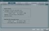
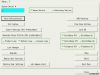


УЗИ аппарат SonoAce-R3 (Samsung Medison, снят с производства)
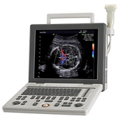
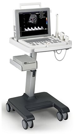
SonoAce R3-RUS — портативный ультразвуковой аппарат компании Samsung Medison с высоким качеством изображения, цветным допплером, современными технологиями и диагностическими возможностями для использования в любой области медицины. Легок в работе, легок на подъем. SonoAce R3-RUS пришел на смену популярной модели SonoAce Pico, по сравнению с предшественником, имеет ряд преимуществ: малый вес, два встроенных порта для подключения датчиков, ЖК монитор — 15″, расширенный динамический диапазон (180 дБ), автоматическую оптимизацию изображения (нажатием одной кнопки), 3 USB порта, технологию FSI.
Область исследований: акушерство и гинекология, абдоминальные исследования и урология, эхокардиография и поверхностно расположенные органы, исследования сосудов, а также нефрология, неонатология.
Базовая комплектация: сканер SonoAce R3 (ЖК-монитор; допплеры: цветной энергетический и импульсно-волновой, высокочастотный импульсный; 2-я гармоника; FreeHand 3D; SonoView; 3 USB-порта), флакон геля 250 мл и руководство оператора.
Опции для аппарата SonoAce R3: кардиопакет, тележка, устройства хранения информации (USB флеш-карта, USB флеш-диск); система DICOM.
Основные характеристики аппарата SonoAce R3
- Портативный ультразвуковой сканер.
- ЖК-монитор.
- Кардиопакет (опция).
- Режимы сканирования: B, 2B, M, B+M, 4B;
— CFM — цветное допплеровское картирование;
— PD — энергетический допплер;
— PW — импульсный допплер;
— HPRF — высокочастотный импульсный допплер. - Особенности сканирования:
— дуплексный и триплексный режим;
— трапециевидный режим сканирования для линейных датчиков;
— тканевая гармоника (регистрация 2-й гармоники эхосигнала, в том числе с помощью инверсивной технологии);
— увеличение в реальном масштабе времени;
— автоматический анализ допплеровских кривых;
— глубина сканирования до 30 см;
— steering — возможность изменения допплеровского угла в режимах CFM и PD;
— дуплексный и триплексный режим. - Разъемы для одновременного подключения 2-х датчиков.
- USB 2.0 (3 порта).
- Кинопамять, эргономичная клавиатура, мультичастотные датчики.
- Система FreeHand 3D — восстановление объемной структуры поверхностей тканей (функции увеличения, вращения и т.д.) при работе с обычными датчиками.
- Система SonoView — система архивации и дальнейшего просмотра статических и динамических изображений (база данных изображений). Имеется возможность проведения измерений в архиве. При наличии соответствующих приводов возможно копирование изображений на компакт-диски, магнитооптику.
- Программы для кардиологических, акушерских, гинекологических, урологических, ангиологических исследований, оценки сердца плода.
- Система DICOM (опция) — возможность сетевой интеграции с PACS-системами (например, для архивации или печати ультразвуковых эхограмм на оборудовании других производителей медтехники).
Технологии и программное обеспечение
- Multi-beam (мульти-луч) — технология цифрового формирования луча (устранение многократного отражения, нелинейного ослабления и неточного времени задержки в отличие от аналоговых систем).
- OTI (Optimum Tissue Imaging) — технология получения оптимального изображения тканей, благодаря коррекции скорости. Функция при помощи которой пользователь может выбрать оптимальную скорость для каждой области исследований, тем самым получая одновременно высокое качество изображений различных видов тканей, таких как жир, мышцы или паренхима печени.
- THI (Tissue Harmonic Imaging), тканевая или 2-я гармоника — повышает качество изображения линейное и контрастное разрешение у трудно визуализируемых пациентов. Данная технология предполагает использование широкополосных датчиков и приемного тракта повышенной чувствительности. Дает преимущество при исследовании пациентов с повышенным весом.
- OHI (Optimized Harmonic Imaging) — объединяет две предыдущие технологии и предназначена для особо трудных для визуализации случаев.
- FINE (Filtered Image for Noise reduction & Edge enhancement) — программа фильтрации ультразвукового изображения. Обеспечивает лучшую контрастность контуров и уменьшает уровень шумов.
- CAFE (Compound Automatic Flash Elemination) — обеспечивает зависимую от используемого режима нелинейную фильтрацию для удаления цветных точек на изображении, возникающих из за мерцающих артефактов. Создает улучшенную визуализацию кровотока во всех допплеровских режимах.
- Quick Scan — ускоренный режим (нажатием одной кнопки) настройки изображения исследуемого органа в B-режиме и D-режиме (настройка оптимальных параметров и фильтров за счет автоматического распознавания исследуемого органа по интеллектуальной базе данных человеческих органов).
- FSI (Full Spectrum Imaging) — технология, которая объединяет ультразвуковую информацию от акустических полос разной частоты, что резко снижает количество артефактов и формирует превосходное изображение с плотной контрастностью и значительно лучшей степенью проникновения.
Пакеты ультразвуковых диагностических программ
- Расчет возраста плода с помощью различных измерений: бипариетального диаметра, длины бедренной кости, копчико-теменного размера, диаметра околоплодного мешка, окружности головы, окружности живота и диаметра живота — возможность оценки возраста плода от 4 недель до родов. Расчет веса плода по методам Shepard, Hadlock, Merz, Osaka University. Расчет предпологаемой даты родов по последней менструации. Автоматическое построение графиков роста и веса плода. Просмотр и изменение таблиц возраста плода.
- Кардиологические измерительные программы: оценка митрального и аортального клапанов; оценка левого желудочка по формулам CUBED, POMBO, TEICHHOLZ и в B-режиме: ESP, EBP, BUL, MSR.
- Программы для расчетов в гинекологии.
- Программы для расчетов в ангиологии.
- Программы для расчетов в урологии.
- Программа оценки тазобедренного сустава плода на предмет дисплазии.
Датчики для аппарата SonoAce R3
Конвексные датчики
Конвексный датчик 2-4 МГц (микроконвексный)
Кардиология, абдоминальные исследования (печень, желчный пузырь, поджелудочная железа, селезенка, глубокие сосуды), почки.
Биопсийный набор: нет.
Акушерские исследования (плод, сердце плода), гинекология (матка, яичники), абдоминальные исследования (печень, желчный пузырь, поджелудочная железа, селезенка, глубокие сосуды), почки.
Биопсийный набор: есть.
Конвексный датчик 4-9 МГц (неонатальный)
Неонатология и педиатрия: абдоминальные исследования, почки, сердце, глубокие сосуды, мозг.
Биопсийный набор: нет.
Конвексный датчик 4-9 МГц (ректо-вагинальный)
Акушерские исследования (ранние сроки), гинекология (матка, яичники), урология (предстательная железа), исследования прямой кишки.
Биопсийный набор: есть.
Линейные датчики
Линейный датчик 5-12/40 МГц
Поверхностные структуры (щитовидная железа, молочная железа, лимфоузлы), мускулоскелетные исследования (суставы, мышцы, подкожные структуры), периферические сосуды.
Биопсийный набор: есть.
Линейный датчик 5-12/60 МГц
Поверхностные структуры (щитовидная железа, молочная железа, лимфоузлы), мускулоскелетные исследования (суставы, мышцы, подкожные структуры), периферические сосуды.
Биопсийный набор: есть.
Внимание! Копирование или частичная перепечатка материалов проспекта сканера «SonoAce R3» на русском языке и размещение в интернет без согласия владельца (ЗАО «Медиэйс») запрещена, запрос на копирование материала можно отправить здесь.
Источник
УЗИ аппарат Samsung Medison SonoAce R3
Скидки и персональные условия у менеджера
УЗИ аппарат SonoAce R3 от компании Самсунг Медисон c широкими диагностическими возможностями и высоким качеством изображения предназначен для использования в любой области медицины. Невысокая цена, мобильность и одновременное подключение двух датчиков делают ультразвуковой сканер SonoAce R3 подходящим для клиник с различным бюджетом. Малый вес и компактные габариты УЗИ системы SonoAce R3 позволяют использовать его в любой части клиники и на дому при выездах к пациентам.
Области применения SonoAce R3
- Акушерство и гинекология
- Абдоминальные исследования
- Урология
- Эхокардиография
- Поверхностно расположенные органы
- Исследования сосудов/Ангиология
- Неонатология
- Нефрология
Режимы сканирования и визуализации:
- B — режим
- M — режим
- CFM — цветное доплеровское картирование
- PD — энергетический допплер
- PW — импульсный допплер
- HPRF — высокочастотный импульсный допплер
- THI — тканевая гармоника
Базовый набор SonoAce R3
- Порты для датчиков: 2
- USB-порты: 3
- SonoView (система архивации)
- Цветной доплер (CD)
- Энергетический доплер (PD)
- Импульсно-волновой доплер (PW)
- Тканевая гармоника (THI)
- FreeHand 3D
- Руководство пользователя
Опции SonoAce R3
- Тележка с разветвителем для датчиков
- Устройства хранения информации (USB флеш-карта, USB флеш-диск)
- Система DICOM
- Кинопамять — Автоматическая видео-запись части исследования с функцией перемотки, редактирования данных, дополнительного проведения расчетов и запись исследования в файл.
- THI — Тканевая гармоника, также имеет название 2я гармоника — корректирует качество картинки в лучшую сторону, улучшает линейное и контрастное разрешение. Особенно помогает при обследовании трудновизуализируемых пациентов (пациентов с большим весом).
- CAFE (Compound Automatic Flash Elemination) — Опция для улучшения визуализации кровотока в доплеровских режимах за счет обеспечения нелинейной фильтрации и исключения цветных точек на изображении, которые могут появляться из-за мерцающих артефактов.
- FSI (Full Spectrum Imaging) — Сложный алгоритм приема избирательного контрастированного изображения по всей глубине сканирования.
- Quick Scan — Автоматическая настройка оптимальных параметров и фильтров для изображения. При помощи нажатия на одну кнопку в B и D режиме. Автоматическое распознавание исследуемого объекта по интеллектуальной базе данных человеческих органов.
- OTI (Optimum Tissue Imaging) — Опция для получение лучшей визуализации тканей за счет коррекции скорости. Благодаря этой функции у специалиста есть возможность выбрать нужную скорость для определенной области исследования, получая отличное качество картинки разных видов тканей.
- OHI (Optimized Harmonic Imaging) — Объединяет функции OHI и THI, подходит для визуализации достаточно сложных случаев.
- FINE (Filtered Image for Noise reduction & Edge enhancement) — Функция для уменьшения уровня шума и увеличения контрастности контуров.
- Multi-beam (мульти-луч) Multi-beam (мульти-луч) — Технология цифрового создания луча для удаления многократного отображения, нелинейного ослабления и неточного времени задержки по сравнению с аналоговыми системами.
Пакеты опций
Кардиопакет:
- Тканевый допплер (TDI)
- Анатомический М-режим
- Цветной М-режим (CM)
- Программное обеспечение
- Постоянно-волновой доплер CW
- Порт для карандашных датчиков
- Пакет кардиологических расчетов.
Совместимые датчики:
- C2-8 (2-8МГц) — Конвексный датчик
- LN5-12 (5-12 МГц) — Линейный датчик
- CN4-9 (4-9 МГц) — Микроконвексный датчик
- EC4-9 (4-9 МГц) — Внутриполостной датчик
- LN5-12/40 (5-12 МГц) — Линейный датчик
Источник
УЗИ сканер SonoAce R3
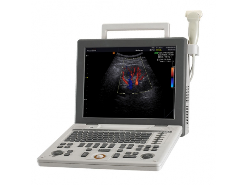


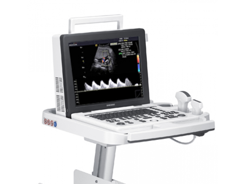
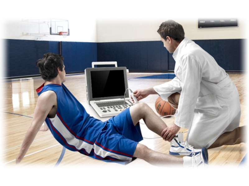
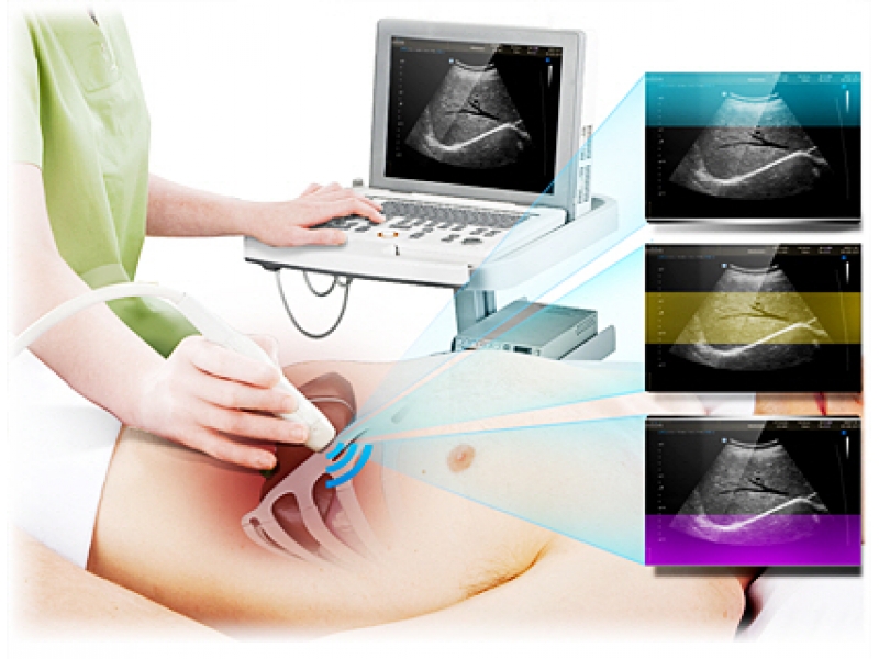

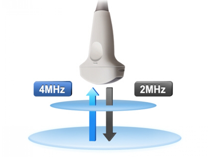
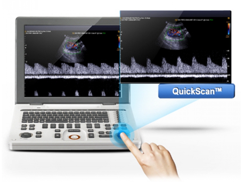

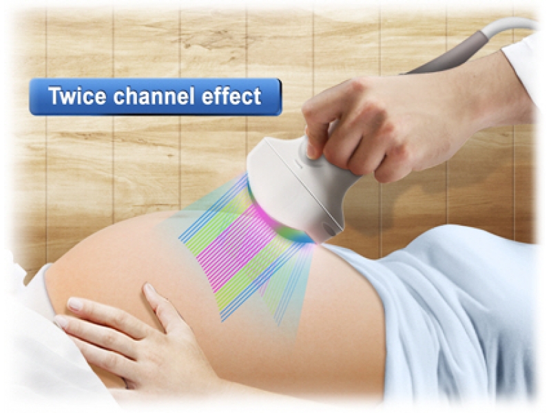
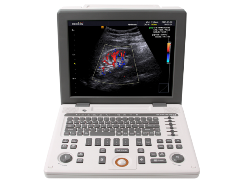

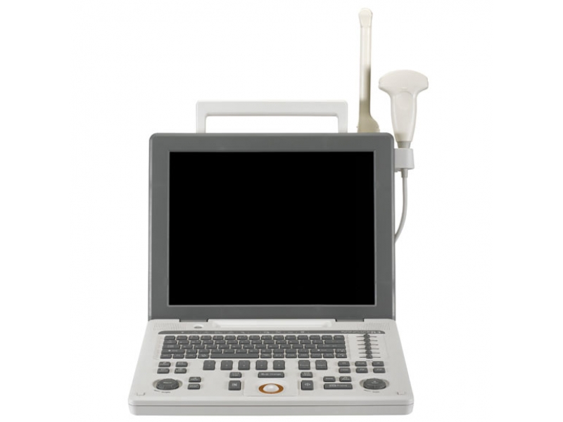
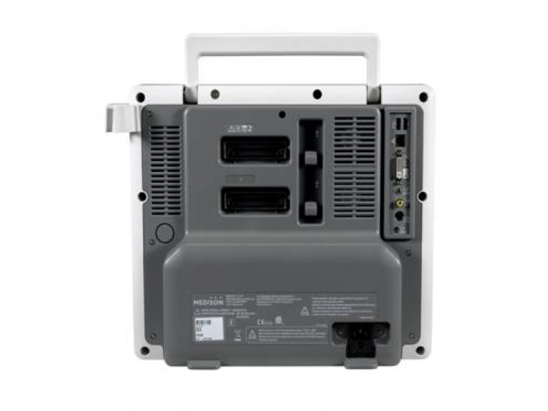
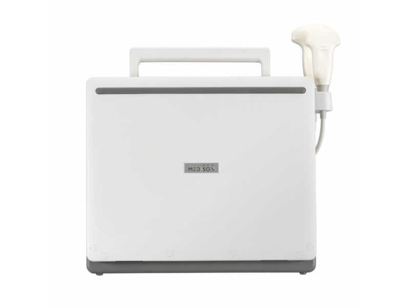
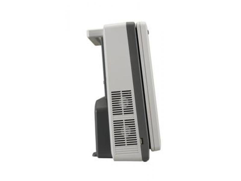


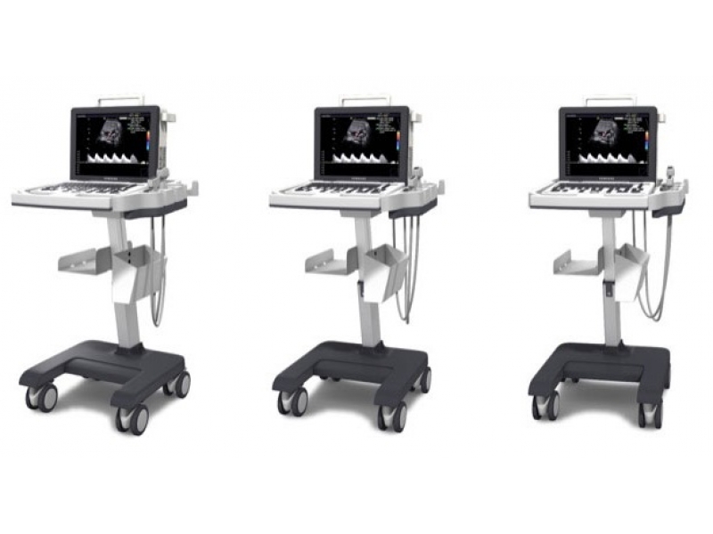

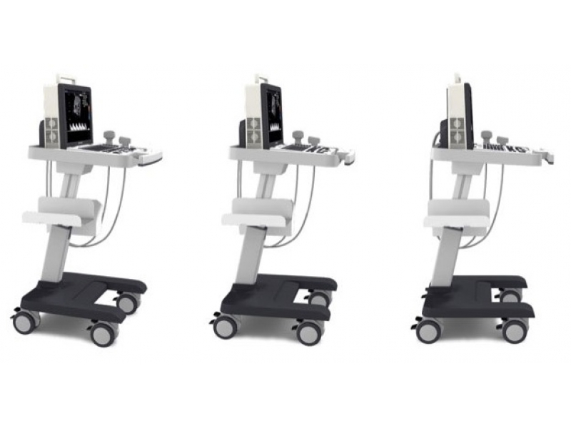
О товаре
SonoAce R3 — портативный ультразвуковой аппарат компании Samsung Medison с высоким качеством изображения, цветным допплером, современными технологиями и диагностическими возможностями для использования в любой области медицины. Легок в работе, легок на подъем. SonoAce R3 пришел на смену популярной модели SonoAce-Pico, по сравнению с предшественником, имеет ряд преимуществ: малый вес, два встроенных порта для подключения датчиков, ЖК монитор — 15″, расширенный динамический диапазон (180 дБ), автоматическую оптимизацию изображения (нажатием одной кнопки), 3 USB порта, технологию FSI.
Область исследований: акушерство и гинекология, абдоминальные исследования и урология, эхокардиография и поверхностно расположенные органы, исследования сосудов, а также нефрология, неонатология.
Базовая комплектация: сканер R3 (ЖК-монитор; допплеры: цветной энергетический и импульсно-волновой, высокочастотный импульсный; 2-я гармоника; FreeHand 3D; SonoView; 3 USB-порта), флакон геля 250 мл и руководство оператора.
Опции для аппарата SonoAce R3: кардиопакет, тележка, устройства хранения информации (USB флеш-карта, USB флеш-диск); система DICOM.
Основные характеристики аппарата SonoAce R3
Портативный ультразвуковой сканер.
Режимы сканирования: B, 2B, M, B+M, 4B;
— CFM — цветное допплеровское картирование;
— PD — энергетический допплер;
— HPRF — высокочастотный импульсный допплер.
— дуплексный и триплексный режим;
— трапециевидный режим сканирования для линейных датчиков;
— тканевая гармоника (регистрация 2-й гармоники эхосигнала, в том числе с помощью инверсивной технологии);
— увеличение в реальном масштабе времени;
— автоматический анализ допплеровских кривых;
— глубина сканирования до 30 см;
— steering — возможность изменения допплеровского угла в режимах CFM и PD;
— дуплексный и триплексный режим.
Разъемы для одновременного подключения 2-х датчиков.
Кинопамять, эргономичная клавиатура, мультичастотные датчики.
Система FreeHand 3D — восстановление объемной структуры поверхностей тканей (функции увеличения, вращения и т.д.) при работе с обычными датчиками.
Система SonoView — система архивации и дальнейшего просмотра статических и динамических изображений (база данных изображений). Имеется возможность проведения измерений в архиве. При наличии соответствующих приводов возможно копирование изображений на компакт-диски, магнитооптику.
Программы для кардиологических, акушерских, гинекологических, урологических, ангиологических исследований, оценки сердца плода.
Система DICOM (опция) — возможность сетевой интеграции с PACS-системами (например, для архивации или печати ультразвуковых эхограмм на оборудовании других производителей медтехники).
Технологии и программное обеспечение
Multi-beam (мульти-луч) — технология цифрового формирования луча (устранение многократного отражения, нелинейного ослабления и неточного времени задержки в отличие от аналоговых систем).
OTI (Optimum Tissue Imaging) — технология получения оптимального изображения тканей, благодаря коррекции скорости. Функция при помощи которой пользователь может выбрать оптимальную скорость для каждой области исследований, тем самым получая одновременно высокое качество изображений различных видов тканей, таких как жир, мышцы или паренхима печени.
THI (Tissue Harmonic Imaging), тканевая или 2-я гармоника — повышает качество изображения линейное и контрастное разрешение у трудно визуализируемых пациентов. Данная технология предполагает использование широкополосных датчиков и приемного тракта повышенной чувствительности. Дает преимущество при исследовании пациентов с повышенным весом.
OHI (Optimized Harmonic Imaging) — объединяет две предыдущие технологии и предназначена для особо трудных для визуализации случаев.
FINE (Filtered Image for Noise reduction & Edge enhancement) — программа фильтрации ультразвукового изображения. Обеспечивает лучшую контрастность контуров и уменьшает уровень шумов.
CAFE (Compound Automatic Flash Elemination) — обеспечивает зависимую от используемого режима нелинейную фильтрацию для удаления цветных точек на изображении, возникающих из за мерцающих артефактов. Создает улучшенную визуализацию кровотока во всех допплеровских режимах.
Quick Scan — ускоренный режим (нажатием одной кнопки) настройки изображения исследуемого органа в B-режиме и D-режиме (настройка оптимальных параметров и фильтров за счет автоматического распознавания исследуемого органа по интеллектуальной базе данных человеческих органов).
FSI (Full Spectrum Imaging) — технология, которая объединяет ультразвуковую информацию от акустических полос разной частоты, что резко снижает количество артефактов и формирует превосходное изображение с плотной контрастностью и значительно лучшей степенью проникновения.
Пакеты ультразвуковых диагностических программ
Расчет возраста плода с помощью различных измерений: бипариетального диаметра, длины бедренной кости, копчико-теменного размера, диаметра околоплодного мешка, окружности головы, окружности живота и диаметра живота — возможность оценки возраста плода от 4 недель до родов. Расчет веса плода по методам Shepard, Hadlock, Merz, Osaka University. Расчет предпологаемой даты родов по последней менструации. Автоматическое построение графиков роста и веса плода. Просмотр и изменение таблиц возраста плода.
Кардиологические измерительные программы: оценка митрального и аортального клапанов; оценка левого желудочка по формулам CUBED, POMBO, TEICHHOLZ и в B-режиме: ESP, EBP, BUL, MSR.
Программы для расчетов в гинекологии.
Программы для расчетов в ангиологии.
Программы для расчетов в урологии.
Программа оценки тазобедренного сустава плода на предмет дисплазии.
Датчики для аппарата SonoAce R3
Конвексные датчики
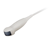
Конвексный датчик 2-4 МГц (микроконвексный)
Кардиология, абдоминальные исследования (печень, желчный пузырь, поджелудочная железа, селезенка, глубокие сосуды), почки.
Биопсийный набор: нет.
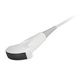
Акушерские исследования (плод, сердце плода), гинекология (матка, яичники), абдоминальные исследования (печень, желчный пузырь, поджелудочная железа, селезенка, глубокие сосуды), почки.
Биопсийный набор: есть.
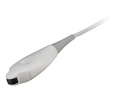
Конвексный датчик 4-9 МГц (неонатальный)
Неонатология и педиатрия: абдоминальные исследования, почки, сердце, глубокие сосуды, мозг.
Биопсийный набор: нет.
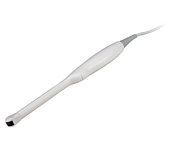
Конвексный датчик 4-9 МГц (ректо-вагинальный)
Акушерские исследования (ранние сроки), гинекология (матка, яичники), урология (предстательная железа), исследования прямой кишки.
Биопсийный набор: есть.
Линейные датчики
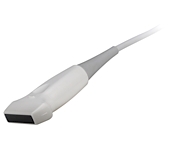
Линейный датчик 5-12/40 МГц
Поверхностные структуры (щитовидная железа, молочная железа, лимфоузлы), мускулоскелетные исследования (суставы, мышцы, подкожные структуры), периферические сосуды.
Биопсийный набор: есть.
Линейный датчик 5-12/60 МГц
Поверхностные структуры (щитовидная железа, молочная железа, лимфоузлы), мускулоскелетные исследования (суставы, мышцы, подкожные структуры), периферические сосуды.
Биопсийный набор: есть.
УЗИ сканер SonoAce R3 по отличной цене в Москве от компании EuroSMed. На нашем сайте представлены характеристики, описания и информация о покупке. Купите Ультразвуковые сканеры с доставкой.
Источник