-
Руководства по ремонту
1
-
Инструкции по эксплуатации
1

SONY CDX-CA600 инструкция по эксплуатации
(132 страницы)
- Языки:Английский, Итальянский, Немецкий, Нидерландский, Французский
-
Тип:
PDF -
Размер:
1.53 MB
Просмотр
На NoDevice можно скачать инструкцию по эксплуатации для SONY CDX-CA600. Руководство пользователя необходимо для ознакомления с правилами установки и эксплуатации SONY CDX-CA600. Инструкции по использованию помогут правильно настроить SONY CDX-CA600, исправить ошибки и выявить неполадки.
инструкцияSony CDX-CA600

3-238-730-31 (1)FM/MW/LW Compact Disc Player
CDX-CA600X
CDX-CA600
2002 Sony Corporation
FM/MW/LW
Compact Disc Player
Operating Instructions
Bedienungsanleitung
Mode d’emploi
Istruzioni per l’uso
Gebruiksaanwijzing
GB
DE
IT
FR
NL
Wichtig!
Bitte nehmen Sie sich etwas Zeit, um den Geräte-Pass
vollständig auszufüllen. Dieser befindet sich auf der
hinteren Umschlagseite dieser Bedienungsanleitung.
Si dichiara che l’apparecchio è stato fabbricato in conformità all’art. 2, Comma 1 del
D.M. 28.08.1995 n. 548.
For installation and connections, see the supplied installation/connections
manual.
Zur Installation und zum Anschluß siehe die mitgelieferte Installations-/
Anschlußanleitung.
En ce qui concerne l’installation et les connexions, consulter le manuel
d’installation/connexions fourni.
Per l’installazione e i collegamenti, fare riferimento al manuale di istruzioni di
installazione/collegamenti in dotazione.
Zie voor het monteren en aansluiten van het apparaat de bijgeleverde handleiding
“Installatie en aansluitingen”.
Посмотреть инструкция для Sony CDX-CA600 бесплатно. Руководство относится к категории автомагнитолы, 1 человек(а) дали ему среднюю оценку 5.1. Руководство доступно на следующих языках: английский. У вас есть вопрос о Sony CDX-CA600 или вам нужна помощь? Задайте свой вопрос здесь
Главная
| Sony | |
| CDX-CA600 | |
| автомагнитола | |
| английский | |
| Руководство пользователя (PDF), Инструкция по установке (PDF) |
Не можете найти ответ на свой вопрос в руководстве? Вы можете найти ответ на свой вопрос ниже, в разделе часто задаваемых вопросов о Sony CDX-CA600.
Не нашли свой вопрос? Задайте свой вопрос здесь
AUDIO OUT
REAR
BUS AUDIO
IN
1
Sony Corporation © 2001 Printed in Thailand
3-227-103-31 (1)
1
3
4
2
6
8
Equipment used in illustrations (not supplied)
Vybavení použité pro ilustrace (není součástí příslušenství)
Wyposażenie wykorzystane w celach ilustracyjnych (nie załączone)
Örneklerde kullan lan alet (beraberinde değil)
Аппаратура, фигурирующая в иллюстрациях (не прилагается)
1
Ч
2
5
7
3
Ч
2
9
1 3 5 7
2 4
6 8
5 7
4
8
2
B
A
XR-CA600X
XR-L500X
XR-CA600V
XR-L500V
XR-CA600
XR-L500
BUS CONTROL IN
BUS AUDIO IN
BUS AUDIO IN
BUS CONTROL IN
AUDIO OUT
AUDIO OUT
Cautions
• This unit is designed for negative earth 12 V DC operation only.
• Do not get the wires under a screw, or caught in moving parts
(e.g. seat railing).
• Before making connections, turn the car ignition off to avoid
short circuits.
• Connect the power connecting cord 8 to the unit and speakers
before connecting it to the auxiliary power connector.
• Run all earth wires to a common earth point.
• Be sure to insulate any loose unconnected wires with electrical
tape for safety.
Notes on the power supply cord (yellow)
• When connecting this unit in combination with other stereo
components, the connected car circuit’s rating must be higher
than the sum of each component’s fuse.
• When no car circuits are rated high enough, connect the unit
directly to the battery.
Power connection
Power connectors may vary depending on the car. Check your
car’s power connector diagram to make sure the connections
match correctly. There are two basic types. You may need to
switch the positions of the jump connector. Before connecting the
unit to the car’s power supply, be sure to match the position of the
jump connector to the car’s pin order. If the power connector of
your car does not match the connector on the unit, use the
supplied connector 8. If you have any questions or problems
connecting your unit that are not covered in this manual, please
consult the car dealer.
WARNING
Shifting the fuse
Check the pin position of the power connector of the car with the
table on the below. If positions 4 and 7 are reversed, remove the
fuse and shift it to the lower position as shown in the illustration.
Parts list (1)
The numbers in the list are keyed to those in the instructions.
Caution
Handle the bracket 1 carefully to avoid injuring your fingers.
Connection example (2)
Notes (2-A,-B-
)
• Be sure to connect the earth cord before connecting the
amplifier.
• If you connect an optional power amplifier and do not use the
built-in amplifier, the beep sound will be deactivated.
Tip (2-B-
)
For connecting two or more changers, the source selector XA-C30
(optional) is necessary.
Connection diagram (3)
A
To AMP REMOTE IN of an optional power amplifier
This connection is only for amplifiers. Connecting any other
system may damage the unit.
B
To the interface cable of a car telephone
Warning
If you have a power aerial without a relay box, connecting this unit
with the supplied power connecting cord 8 may damage the
aerial.
Notes on the control leads
• The power aerial control lead (blue) supplies +12 V DC when you
turn on the tuner or when you activate the ATA (Automatic Tuner
Activation), AF (Alternative Frequency) or the TA (Traffic
Announcement) function.
• When your car has built-in FM/MW/LW aerial in the rear/side
glass, connect the power aerial control lead (blue) or the
accessory power input lead (red) to the power terminal of the
existing aerial booster. For details, consult your dealer.
• A power aerial without a relay box cannot be used with this unit.
Memory hold connection
When the yellow power input lead is connected, power will always
be supplied to the memory circuit even when the ignition switch is
turned off.
Notes on speaker connection
• Before connecting the speakers, turn the unit off.
• Use speakers with an impedance of 4 to 8 ohms, and with
adequate power handling capacities to avoid its damage.
• Do not connect the speaker terminals to the car chassis, or
connect the terminals of the right speakers with those of the left
speaker.
• Do not attempt to connect the speakers in parallel.
• Connect only passive speakers. Connecting active speakers (with
built-in amplifiers) to the speaker terminals may damage the unit.
1
Pozor
• Tento přístroj je konstruován výhradně pro stejnosměrný proud
12 V a negativní uzemnění.
• Vodiče by se neměly dostat do kontaktu se šroubovákem ani s
pohybujícími se díly (např. do kolejnic sedadel).
• Než provedete připojení, vypněte zapalování, aby nedošlo ke
zkratu.
• Před připojením na pomocné napájecí konektory zapojte
napájecí kabel 8 do přístroje a do reproduktorů.
• Všechny dráty pro uzemnění zapojte do společného bodu.
• Nezapomeňte všechny volné nezapojené vodiče z
bezpečnostních důvodů zaizolovat páskou.
Poznámky týkající se napájecího kabelu (žlutý)
• Při zapojování tohoto přístroje v kombinaci s dalšími
stereofonními komponenty musí být proud v obvodu automobilu
vyšší než součet hodnot pojistek jednotlivých komponent.
• Není-li k dispozici obvod s dostatečnou kapacitou, připojte
přístroj přímo k baterii.
Zapojení proudu
Konektory pro zapojení proudu mohou být u různých aut různé. Ve
schématu elektrických obvodů k vašemu autu se přesvědčte,
jsou-li konektory správné. Existují dva základní druhy. Může se
stát, že budete muset přepnout polohu nastavitelného konektoru.
Než zapojíte přístroj na zdroj proudu v autě, přesvědčte se, zda
poloha nastavitelného konektoru odpovídá pořadí kolíků v autě.
Jestliže konektor zdroje proudu ve vašem autě neodpovídá
konektoru na přístroji, použijte konektor 8 z příslušenství. Jestliže
máte další otázky nebo jestliže se vyskytnou problémy v
souvislosti s tímto přístrojem, které nejsou popsány v tomto
návodu, obra te se na vaši autodílnu.
UPOZORNĚNÍ
Posunutí pojistky
Porovnejte polohu kolíků zástrčky na přívod proudu ve vašem
autě s tabulkou níže. Jestliže jsou pozice 4 a 7 obrácené, vyjměte
pojistku a posuňte ji do nižší polohy podle ilustrace.
Seznam součástí (1)
Čísla v seznamu odpovídají číslům v návodu.
Upozornění
S konzolou 1 zacházejte opatrně, abyste si přitom neporanili
prsty.
Příklad zapojení (2)
Poznámky (2-A, B-
)
• Dbejte na to, abyste napřed zapojili kabel pro uzemnění, než zapojíte
zesilovač.
• Připojíte-li přídavný zesilovač a nepoužijete vestavěný zesilovač,
nebude zvukový signál aktivován.
Tip (2-B-
)
Pro zapojení dvou nebo více měničů je zapotřebí přepínač zdroje
XA-C30 (možno dokoupit).
Schéma zapojení (3)
A
Zdířka AMP REMOTE IN přídavného zesilovače
Toto zapojení je určeno pouze pro zesilovače. Zapojením jiného
zařízení může dojít k poškození přístroje.
B
Do kabelu rozhraní telefonu v autě
Upozornění
Jestliže máte anténu bez relé, může při jejím zapojení na tento
přístroj za pomoci kabelu 8 z příslušenství dojít k poškození
antény.
Poznámky k přívodním kabelům
• Kabel pro ovládání elektrické antény (modrý) dodává stejnosměrný
proud +12 V, jakmile zapnete rádio nebo jakmile zaktivujete jednu z
funkcí ATA (Automatic Tuner Activation — automatická aktivace
tuneru), AF (Alternative Frequency — alternativní frekvence) nebo TA
(Traffic Announcement — dopravní hlášení).
• Je-li vaše vozidlo vybaveno anténou FM/MW/LW vestavěnou do
zadního či bočního skla, zapojte napájecí vodič ovládání antény
(modrý) nebo červený napájecí vodič přídavných doplňků (červený)
do zdířky stávajícího anténního zesilovače. Podrobné informace
získáte u svého prodejce.
• S tímto přístrojem nelze používat elektrickou anténu bez relé.
Zapojení pro uchování paměti
Je-li zapojený žlutý kabel pro napájení přístroje, bude okruh paměti
pod proudem i při vypnutém klíčku zapalování.
Poznámky k zapojení reproduktorů
• Než začnete se zapojováním reproduktorů, vypněte přístroj.
• Používejte reproduktory s impedancí od 4 do 8 ohmů a s
odpovídajícím výkonem. Jinak by mohlo dojít k jejich poškození.
• Nezapojujte vývody od reproduktorů na podvozek vozidla a
nezapojujte vývod pravého reproduktoru společně s vývodem levého
reproduktoru.
• Nepokoušejte se zapojit reproduktory paralelně.
• Do svorek tohoto přístroje nezapojujte žádné aktivní reproduktory (se
zabudovaným zesilovačem). Mohlo by to vést k poškození aktivních
reproduktorů. Proto se přesvědčte, abyste na tento přístroj zapojili
pasivní reproduktory.
Ostrzeżenie
• Sprzęt przeznaczono wyłącznie do zasilania napięciem stałym
12 V z uziemieniem ujemnym.
• Nie wolno dopuścić, aby przewody dostały się pod wkręty lub w
pobliże ruchomych części samochodu (np. między siedzenie a
szyny siedzenia).
• Przed wykonaniem podłączeń należy wyłączyć stacyjkę
samochodu, aby uniknąć zwarcia.
• Przewód zasilania 8 należy przed podłączeniem do
pomocniczego złącza zasilania podłączyć w pierwszej kolejności
do sprzętu i do głośników.
• Wszystkie przewody uziemiające należy poprowadzić do
wspólnego punktu uziemienia.
• Należy upewnić się, że wszystkie luźne przewody, które nie
zostały podłączone, są zabezpieczone taśmą izolacyjną.
Uwagi dotyczące przewodu zasilającego (żółtego)
• Jeśli to urządzenie jest podłączane do innych elementów
wyposażenia stereofonicznego, obwód samochodowy, do
którego urządzenia są podłączone musi mieć wyższą wartość
znamionową niż suma wartości bezpieczników wszystkich
komponentów razem wziętych.
• Jeśli nie ma obwodów o odpowiedniej wartości, należy
podłączyć urządzenie bezpośrednio do akumulatora.
Łącza zasilania
Łącza zasilania mogą zależeć od typu pojazdu. Należy sprawdzić
schemat samochodowych łączy zasilania, aby zapewnić właściwe
dopasowanie połączeń. W zasadzie istnieją dwa podstawowe typy.
Przełączenie pozycji zacisków łączeniowych może okazać się
konieczne. Przed podłączeniem sprzętu do samochodowego źródła
zasilania należy upewnić się że pozycja zacisków łączeniowych
odpowiada wtykom samochodowym. Jeśli łącze zasilania pojazdu
nie pasuje do łącza sprzętu, należy użyć dostarczonych łączy 8. W
przypadku ewentualnych wątpliwości lub trudności z podłączeniem
sprzętu nie opisanych w podręczniku należy skonsultować się z
punktem sprzedaży pojazdu.
OSTRZEŻENIE
Zmiana pozycji umiejscowienia bezpiecznika
Należy sprawdzić pozycję wtyku łącza zasilania w porównaniu z
tabelą poniżej. Jeśli pozycje 4 i 7 są odwrócone, bezpiecznik
trzeba umieścić niżej, zgodnie z ilustracją.
Spis elementów montażowych (1)
Numery podane w spisie odpowiadają numerom używanym w
instrukcjach.
Ostrzeżenie
Aby uniknąć obrażeń ciała, należy przy montażu wspornika 1,
podjąć odpowiednie środki ostrożności.
Przykład wykonania podłączenia (2)
Uwagi (2-A , B-
)
• Przed podłączeniem do wzmacniacza należy w pierwszej kolejności
podłączyć przewód uziemienia.
• Podłączenie opcjonalnego wzmacniacza mocy powoduje wyłączenie
wbudowanego wzmacniacza i sygnalizacji dźwiękowej.
Wskazówka (2-B-
)
Do podłączenia dwóch lub więcej zmieniaczy płyt niezbędny jest
selektor źródła XA-C30 (opcjonalny).
Schemat podłączeń (3)
A
Do wejścia AMP REMOTE IN opcjonalnego wzmacniacza mocy
To złącze jest przeznaczone wyłącznie dla wzmacniaczy.
Podłączanie innych komponentów może spowodować uszkodzenie
urządzenia.
B
Do przewodu interfejsu samochodowego telefonu komórkowego
Ostrzeżenie
Jeśli używana antena automatyczna nie jest wyposażona w
skrzynkę przekaźnikową, przeprowadzenie podłączenia sprzętu
dostarczonym przewodem 8 może spowodować uszkodzenie
anteny.
Uwagi na temat przewodów sterujących
• Przewód sterujący anteną automatyczną (niebieski) dostarcza +12 V
DC po włączeniu sprzętu lub funkcji ATA (Automatic Tuner Activation
= automatyczne uaktywnienie tunera), funkcji AF (Alternative
Frequency = alternatywne częstotliwości) lub funkcji TA (Traffic
Announcement = komunikaty o ruchu drogowym).
• Gdy w samochodzie znajduje się antena FM/MW/LW wbudowana w
tylną lub boczną szybę, należy podłączyć przewód sterowania
anteną (niebieski) lub dodatkowy przewód zasilający (czerwony) do
przewodu zasilającego istniejący wzmacniacz antenowy. Aby
uzyskać więcej informacji, należy skontaktować się ze sprzedawcą.
• Antena automatyczna bez skrzynki przekaźnikowej nie nadaje się do
użytku z tym sprzętem.
Wspomaganie pamięci sprzętu
Podłączenie żółtego przewodu doprowadzania zasilania umożliwia
stały dopływ mocy do obwodu wspomagania pamięci, nawet przy
wyłączonym zapłonie.
Uwagi dotyczące podłączania głośników
• Przed podłączeniem głośników należy pamiętać o wyłączeniu
zasilania sprzętu.
• Należy podłączyć głośniki o impedancji od 4 do 8 omów i
odpowiedniej mocy. W przeciwnym przypadku może nastąpić
uszkodzenie głośników.
• Nie należy podłączać złączy systemu głośnikowego do karoserii lub
też złączy prawego do złączy lewego głośnika.
• Głośników nie należy podłączać równolegle.
• Do gniazdek głośnikowych sprzętu nie należy podłączać głośników
aktywnych (wyposażonych we wzmacniacze). Może nastąpić
uszkodzenie głośników aktywnych. Należy upewnić się, że
podłączane głośniki są typu pasywnego.
Предостережение
• Данная автомагнитола предназначена для подключения
только к 12-вольтному аккумулятору постоянного тока с
отpицaтeльным заземлением.
• He допycкaйтe попaдaния пpоводов под винты или мeждy
подвижными дeтaлями (нaпpимep, мeждy нaпpaвляющими
cидeний).
• Пepeд выполнeниeм cоeдинeния выключитe зaжигaниe
aвтомобиля во избeжaниe коpоткого зaмыкaния.
• Сначала подсоедините шнур питания к магнитоле и
громкоговорителям, а уже потом 8 к контактам внешнего
источника питания.
• Подведите все провода заземления к одной и той же
точке заземления.
• B цeляx бeзопacноcти обязaтeльно изолиpyйтe вce cвободныe
нeподcоeдинeнныe пpоводa изоляционной лeнтой.
Пpимeчaния отноcитeльно шнypa питaния (жeлтого)
• Пpи подключeнии дaнного ycтpойcтвa вмecтe c дpyгими
cтepeокомпонeнтaми номинaльноe знaчeниe cилы токa в
контype питaния aвтомобиля должно пpeвышaть cyммapноe
знaчeниe cилы токa, yкaзaнноe нa пpeдоxpaнитeляx вcex
компонeнтов.
• Ecли номинaльноe знaчeниe cилы токa в контype питaния
aвтомобиля нe доcтaточно выcокоe, подcоeдинитe
ycтpойcтво нaпpямyю к aккyмyлятоpy.
Подключeниe питaния
Paзъeмы питaния могyт paзличaтьcя в зaвиcимоcти от типa
aвтомобиля. Чтобы yбeдитьcя в пpaвильноcти cоeдинeний,
cвepьтecь cо cxeмой paзъeмов питaния для Baшeго aвтомобиля.
Cyщecтвyeт двa оcновныx типa. Bозможно, потpeбyeтcя cмeнить
позиции пepeмычки. Пepeд подcоeдинeниeм ycтpойcтвa к
иcточникy питaния aвтомобиля обязaтeльно cоглacyйтe
положeниe пepeмычки c pacположeниeм контaктов в paзъeмe
aвтомобиля. Ecли paзъeм питaния aвтомобиля нe cоотвeтcтвyeт
paзъeмy нa ycтpойcтвe, воcпользyйтecь пpилaгaeмым paзъeмом
8
. Ecли во вpeмя подключeния ycтpойcтвa возникнyт вопpоcы
или тpyдноcти, котоpыe нe paccмотpeны в нacтоящeм
pyководcтвe, обpaтитecь к дилepy по пpодaжe aвтомобилeй.
ПPEДУПPEЖДEHИE
Перемещение предохранителя
Проверьте положение штырька разъема контактов питания
автомобиля по таблице ниже. Если позиции 4 и 7 перепутаны,
снимите предохранитель и переместите его ниже, как
показано на иллюстрации.
Перечень деталей (1)
Нижеприводимые цифры соответствуют цифрам,
упоминаемым далее в данной инструкции.
Bнимaниe
Обращайтесь с консолью 1 осторожно, чтобы не повредить
пальцы.
Пример подсоединения (2)
Примечания (2-A, B-
)
• Прежде чем подключать магнитолу к усилителю, обязательно
подсоедините провод заземления.
• Ecли подключaeтcя дополнитeльный ycилитeль мощноcти, a
вcтpоeнный ycилитeль нe иcпользyeтcя, звyковой cигнaл бyдeт
отключeн.
Совет (2-B-
)
Для подсоединения двух или более проигрывателей компакт-дисков
необходим селектор источника XA-C30 (в комплект не входит).
Схема подсоединения (3)
A
Подключeниe к вxодy AMP REMOTE IN дополнитeльного
ycилитeля мощноcти
Этот вapиaнт подключeния иcпользyeтcя только для
ycилитeлeй. Подключeниe любой дpyгой cиcтeмы можeт
пpивecти к повpeждeнию ycтpойcтвa.
B
К интepфeйcномy кaбeлю aвтомобильного тeлeфонa
Предостережение
Если Вы используете антенну с электрическим приводом без
релейного блока, подсоединение данной магнитолы
посредством прилагаемого шнура питания 8 может привести
к повреждению антенны.
О проводах управления
• По (синему) проводу питания антенны с электрическим
приводом осуществляется подача постоянного тока силой +12
вольт при включении Вами радиоприемника или функций АТА
(автоматическая активация приемника), AF (альтернативные
частоты) и ТА (дорожные сообщения).
• Ecли нa зaднeм/боковом cтeклe aвтомобиля ycтaновлeнa
вcтpоeннaя aнтeннa диaпaзонa FM/MW/LW, подcоeдинитe
пpовод питaния пpиeмной aнтeнны (cиний) или пpовод питaния
ycтpойcтвa (кpacный) к клeммe питaния cyщecтвyющeго
ycилитeля aнтeнны. Чтобы полyчить дополнитeльныe cвeдeния,
обpaтитecь к cвоeмy дилepy.
• Антенна с электрическим приводом, не снабженная релейным
блоком, с данной магнитолой использоваться не может.
Подсоединение для поддержки памяти
Когда к магнитоле подсоединен желтый электрический провод,
блок памяти будет постоянно получать питание, даже при
выключенном зажигании.
О подсоединении громкоговорителей
• Прежде чем подсоединять громкоговорители, выключите магнитолу.
• Используйте громкоговорители с полным сопротивлением 4 — 8
Ом, обладающие способностью принимать достаточно мощный
сигнал. В противном случае они могут быть повреждены.
• Не подсоединяйте контактные гнезда громкоговорителей к
шасси автомобиля и не соединяйте гнезда правого
громкоговорителя с гнездами левого.
• Не пытайтесь подсоединить громкоговорители параллельно.
• Не подсоединяйте к гнездам для громкоговорителей на
магнитоле какие бы то ни было активные громкоговорители (со
встроенными усилителями), поскольку это может привести к
повреждению последних. Убедитесь в том , что подсоединяемые
громкоговорители относятся к пассивному типу.
Dikkat
• Ünite yaln z negatif toprak 12 V DC işlemi için dizayn edilmiştir.
• Telleri bir vidan n alt nda veya (ör. yatak ray ) hareketli parçalara
tak l kalacak şekilde b rakmay n.
• Bağlant lar yapmadan önce, k sa devre oluşumunu önlemek
için, araba ateşleme düzenini kapat n.
• Güç bağlant kablosunu 8 yard mc güç konektörüne
bağlamadan önce üniteye ve hoparlörlere bağlay n z.
• Tüm toprak kablolar n ortak bir noktada topraklay n.
• Güvenlik amac yla, gevşek ya da bağlanmam ş kablolar elektrik
band yla sararak izole etmeyi unutmay n.
Güç kaynağ kablosu (sar ) üzerindeki notlar
• Bu birimi, diğer stereo bileşenleriyle birlikte bağlarken, bağl
araba devreleri düzeyi, tüm bileşenlerin sigorta toplam ndan
daha yüksek olmal d r.
• Araba devreleri yeterince yüksek derecede değilse, üniteyi
doğrudan aküye bağlay n.
Güç bağlant s
Güç konektörleri otomobil türüne göre çeşitlilik gösterir.
Otomobilinizin güç konektörü şemas n inceleyip bağlant lar n
uygun olduğundan emin olunuz. İki ana tip vard r. Ara konektörün
pozisyonlar n değiştirmeniz gerekebilir. Üniteyi otomobilin güç
desteğine bağlamadan önce, ara konektör pozisyonunun
otomobilin iğne düzenine uygun olduğundan emin olunuz.
Otomobilinizin güç konektörü ünitenin konektörüne uymuyorsa,
ünite beraberindeki konektör 8’i kullan n z. Üniteyi bağlarken bu
k lavuzun içermediği problem veya sorular n z için lütfen otomobil
sat c n za dan ş n z.
UYARI
Sigortan n değiştirilmesi
Otomobilin güç konektöründeki pimin pozisyonunun aşağ daki
tabloya göre kontrol ediniz. 4 ve 7 no.lu pozisyonlar ters ise,
sigortay ç kar n z ve örnekte gösterildiği gibi, daha alçak bir
pozisyona yerleştiriniz.
Yedek parça listesi (1)
Listedeki say lar aç klamalardaki say lara göre ayarlanm şt r.
Uyar lar
Parmaklar n z n yaralanmamas için k zağ dikkatli 1 tutun.
Bağlant örneği (2)
Notlar (2-A, B-
)
• Toprak kablosunu, amplifikatörü bağlamadan önce bağlamaya
dikkat ediniz.
• Yerleşik güç amplifikatörünü kullanmay p seçime bağl bir güç
amplifikatörü bağlarsan z, bip sesi devre d ş kalacakt r.
Öneri (2-B-
)
İki veya daha fazla değiştirici bağlamak için kaynak selektörü XA-C30
(isteğe bağl ) gereklidir.
Bağlant şemas (3)
A
Seçime bağl bir güç amplifikatörü AMP REMOTE IN için
Bu bağlant yaln zca amplifikatörler içindir. Herhangi başka bir
sistemin bağlanmas , birime zarar verebilir.
B
Araç telefonu arabirim kablosuna
Uyar
Röle kutusu olmayan bir elektrik anteniniz varsa, bu üniteyi
beraberindeki güç bağlant kablosu 8’e bağlamak antene zarar
verebilir.
Kontrol kablo notlar
• Güç anten kontrol kablosu (mavi) radyoyu açt ğ n zda veya ATA
(Automatic Tuner Activation), AF (Alternative Frequency) veya TA
(Traffic Announcement) fonksiyonlar n aktive ettiğinizde +12 V DC
verir.
• Araban z n arka cam nda yerleşik FM/MW/LW anteni varsa, anten
kontrolü güç kablosunu (mavi) veya aksesuar güç girişi kablosunu
(k rm z ), varolan anten yükselticisinin güç terminaline bağlay n.
Ayr nt lar için, sat c n za dan ş n.
• Bu ünite ile röle kutusu olmayan bir güç anteni kullan lamaz.
Haf zada tutma bağlant s
Sar güç giriş kablosu bağland ğ nda, kontakt düğmesi kapal olsa
dahi haf za devresine her zaman güç verilecektir.
Hoparlör bağlant notlar
• Hoparlörleri bağlamadan önce, üniteyi kapat n z.
• 4 — 8 ohm dirence ve uygun güç kullan m kapasitesine sahip
hoparlörler kullan n z. Aksi takdirde hoparlörler zarar görebilir.
• Hoparlör sisteminin terminallerini otomobil şasisine bağlamay n z ve
sağ hoparlör terminallerini sol hoparlör terminallerine bağlamay n z.
• Hoparlörleri paralel bağlamaya çal şmay n z.
• Yaln zca pasif hoparlör bağlay n. Hoparlör terminaline aktif hoparlör
(yerleşik amplifikatörlü) bağlamak, üniteye zarar verebilir.
Installation/Connections
Instalace/Zapojení
Instalacja/Podłączenia
Kurma/Bağlant lar
Установка/Подсоединение
FM/MW/LW
Cassette
Car Stereo
Supplied with XA-C30
Dodávaný s XA-C30
Dostarczany z modelem XA-C30
XA-C30 ile sunulur
Прилагается к модели XA-C30
7
from car aerial
*
od autoantény
*
od anteny samochodowej
*
otomobil anteninden
*
от автомобильной
антенны
*
9
AUDIO OUT REAR
BUS AUDIO
IN
REMOTE IN
BUS CONTROL
IN
AMP REM
Max. supply current 0.3 A
Max. proud 0,3 A
Maksymalny prąd zasilania 0,3 A
Azami cereyan desteği 0,3 A
Макс. сила тока 0,3 А
Light blue
Světle modrý
Jasnoniebieski
Aç k mavi
Cвeтло-голyбой
Blue/white striped
Modré/bílé proužky
W niebiesko-białe paski
Mavi/beyaz çizgili
С синей/белой полоской
ATT
RCA pin cord (not supplied)
Kolíkový kabel RCA (není součástí příslušenství)
Kabel z wtykami RCA (nie dostarczony)
RCA pim kablosu (beraberinde değil)
Шнур с контактными штырьками RCA
(не прилагается)
Insert with the cord upwards.
Vložte kabelem směrem nahoru.
Włożyć przewodem skierowanym ku górze.
Kablosu yukar bakacak şekilde tak n.
Вставляется проводом вверх.
continuous power supply
nepřerušovaný zdroj proudu
zasilanie ciągłe
kesintisiz güç kaynağ
непрерывное поступление питания
power aerial control
ovládání elektrické antény
sterowanie anteną
anten kontrolü
антенная электрика
7
8
4
5
switched power supply
přepínatelný zdroj proudu
zasilanie komutowane
ayarlanabilir güç desteği
включенное питание
earth
uzemnění
uziemienie
toprak
земля
Positions 1, 2, 3 and 6 do not have pins.
Položky 1, 2, 3 a 6 nemají kolíky.
Pozycje 1, 2, 3 oraz 6 nie posiadają styków.
1, 2, 3, ve 6 pozisyonlar nda pim yoktur.
Позиции 1, 2, 3 и 6 не имеют контактных штырьков.
Source selector
(not supplied)
Přepínač zdroje (není
součástí příslušenství)
Selektor źródła
(nie dostarczony)
Kaynak selektörü
(beraberinde değil)
Селектор источника
(не прилагается)
XA-C30
Supplied with the CD/MD changer
Dodávaný s měničem CD/MD
Dostarczany ze zmieniaczem płyt CD/MD
CD/MD değiştirici ile sunulur
Прилагается к проигрывателю CD/MD
1
2
3
4
Speaker, Rear, Right
Reproduktor, zadní, pravý
Głośnik, tylny, prawy
Hoparlör, arka, sağ
Громкоговоритель, задний, правый
Speaker, Rear, Right
Reproduktor, zadní, pravý
Głośnik, tylny, prawy
Hoparlör, arka, sağ
Громкоговоритель, задний, правый
Speaker, Front, Right
Reproduktor, zadní, pravý
Głośnik, przedni, prawy
Hoparlör, ön, sağ
Громкоговоритель, передний, правый
Speaker, Front, Right
Reproduktor, zadní, pravý
Głośnik, przedni, prawy
Hoparlör, ön, sağ
Громкоговоритель, передний, правый
5
6
7
8
Speaker, Front, Left
Reproduktor, přední, levý
Głośnik, przedni, lewy
Hoparlör, ön, sol
Громкоговоритель, передний, левый
Speaker, Front, Left
Reproduktor, přední, levý
Głośnik, przedni, lewy
Hoparlör, ön, sol
Громкоговоритель, передний, левый
Speaker, Rear, Left
Reproduktor, zadní, levý
Głośnik, tylny, lewy
Hoparlör, arka, sol
Громкоговоритель, задний, левый
Speaker, Rear, Left
Reproduktor, zadní, levý
Głośnik, tylny, lewy
Hoparlör, arka, sol
Громкоговоритель, задний, левый
Negative polarity positions 2, 4, 6, and 8 have striped cords.
Položky s negativní polaritou 2, 4, 6, a 8 mají proužkované kabely.
Przewody polaryzacji ujemnej 2, 4, 6, oraz 8 oznaczono prążkami.
Negatif kutup pozisyonlar n n 2, 4, 6, ve 8 kablolar çizgilidir.
Позиции отрицательной полярности 2, 4, 6 и 8 имеют провода с полосками.
+
–
+
–
+
–
+
–
from the car’s speaker connector
do konektoru automobilového reproduktoru
do złącza głośnika samochodowego
otomobilin hoparlör konektöründen
от paзъeмa автомобильного громкоговорителя
from the car’s power connector
do přídavného konektoru na proud v autě
do samochodowego pomocniczego złącza
zasilania
otomobilin güç konektöründen
от aвтомобильного paзъeмa питaния
* Note for the aerial connecting
If your car aerial is an ISO (International
Organisation for Standardisation) type, use the
supplied adaptor 7 to connect it.
First connect the car aerial to the supplied
adaptor, then connect it to the aerial jack of
the master unit.
* Poznámka k zapojení antény
Jestliže máte autoanténu ISO (International
Organization for Standardization — Mezinárodní
organizace pro standardizaci), použijte k
zapojení adaptér 7 z příslušenství.
Napřed zapojte autoanténu do adaptéru z
příslušenství, potom ji zapojte do zdířky pro
anténu na přístroji.
* Uwaga dotycząca podłączania anteny
Jeśli antena spełnia wymagania standardu ISO
(International Organization for Standarisation),
do podłączenia należy użyć dostarczonego
adaptera 7.
Antenę samochodową należy podłączyć do
dostarczonego adaptera, a następnie do
gniazdka antenowego na głównym korpusie
sprzętu.
* Anten bağlant s yla ilgili not
Otomobil anteniniz bir ISO (International
Organisation for Standardization) tipi ise
bağlant için ünite ile verilen adaptörü 7
kullan n z.
Önce otomobil antenini alet beraberindeki
adaptöre bağlay n z, ard ndan ana ünitenin
anten jak na bağlay n z.
* Примечание о подсоединении антенны
Если антенна в Вашем автомобиле
относится к типу, утвержденному ISO
(Международной организацией по
стандартизации), используйте для ее
подсоединения переходник 7.
Сначала подсоедините автомобильную
антенну к прилагаемому переходнику, а
затем — к антенному гнезду магнитолы.
8
Equipment used in illustrations (not supplied)
Vybavení použité pro ilustrace (není součástí příslušenství)
Wyposażenie wykorzystane w celach ilustracyjnych (nie załączone)
Örneklerde kullan lan alet (beraberinde değil)
Аппаратура, фигурирующая в иллюстрациях (не прилагается)
Rear speaker
Zadní reproduktor
Tylny głośnik
Arka hoparlör
Задний громкоговоритель
Front speaker
Přední reproduktor
Przedni głośnik
Ön hoparlör
Передний громкоговоритель
CD/MD changer
Měnič CD/MD
Zmieniacz płyt CD/MD
CD/MD değiştirici
Проигрыватель CD/MD
Rotary commander RM-X4S
Otočné dálkové ovládání RM-X4S
Rotacyjny pilot zdalnego sterowania RM-X4S
Döner kumanda RM-X4S
Вращающийся дистанционный переключатель RM-X4S
Power amplifier
Zesilovač
Wzmacniacz mocy
Güç amplifikatörü
Усилитель
Source selector
Přepinač zdroje
Selektor źródła
Kaynak selektörü
Селектор источника
not supplied
není součástí příslušenství
nie załączone
beraberinde değil
не прилагается
XR-CA600X/CA600V/CA600 only
Pouze XR-CA600X/CA600V/CA600
Tylko dla XR-CA600X/CA600V/CA600
Yaln z XR-CA600X/CA600V/CA600 için
Касается только моделей XR-CA600X/CA600V/CA600
1
1
1
XR-CA600X/CA600V/CA600 only
Pouze XR-CA600X/CA600V/CA600
Tylko dla XR-CA600X/CA600V/CA600
Yaln z XR-CA600X/CA600V/CA600 için
Касается только моделей XR-CA600X/CA600V/CA600
Fuse (10 A)
Pojistka (10 A)
Bezpiecznik (10 A)
Sigorta (10 A)
Предохранитель (10 А)
B
A
Yellow
Žlutý
Żółty
Sar
Желтый
Blue
Modrý
Niebieski
Mavi
Голубой
Red
Červený
Czerwony
K rm z
Красный
Black
Černý
Czarny
Siyah
Черный
Purple
Fialový
Fioletowy
Mor
Виолетовый
Green
Zelený
Zielony
Yeşil
Зеленый
White
Bílý
Biały
Beyaz
Белый
Grey
Šedý
Szary
Gri
Серый
*
*
Bezpečnostní upozornění
• Místo pro instalaci vyberte tak, aby přístroj nepřekážel
při běžných činnostech při řízení auta.
• Neinstalujte přístroj na místa, kde by byl vystaven
vysokým teplotám, jako např. přímému slunečnímu
záření nebo teplému vzduchu z topení, nebo kde by
byl vystaven nadměrné prašnosti, vlhkosti nebo
přílišným vibracím.
• Pro bezpečnou a jistou instalaci používejte výhradně
nářadí, které je součástí příslušenství.
• Mezi otvorem pro kazety na tomto přístroji a řadicí
pákou musí být nejméně 15 cm volného prostoru, aby
bylo možné snadno vyměňovat kazety. Místo pro
instalaci zvolte uváženě, aby přístroj nepřekážel při
řazení ani při jiných úkonech během řízení auta.
Úhel montáže
Úhel montáže by neměl přesahovat 20
°.
Snímání a nasazování předního
panelu (4)
Než začnete s montáží přístroje, sejměte přední
panel.
4-A Sejmutí
Před sejímáním předního panelu dbejte na to, abyste
napřed stiskli tlačítko (OFF) — vypnutí přístroje. Potom
stiskněte tlačítko (OPEN), posuňte přední panel lehce
doprava a vyklopte levou stranu.
4-B Nasazení
Nasa te stranu
předního panelu na stranu
na
přístroji podle ilustrace a zatlačte na levou stranu,
dokud nezaklapne.
Příklad montáže (5)
Instalace do přístrojové desky
Upozornění pro případ instalace
v autě bez mezipolohy — poloha
ACC — klíčku od zapalování
Dbejte na to, abyste stisknuli (OFF) na přístroji na
dvě sekundy, aby zhasl displej s hodinami po
vypnutí motoru.
Jestliže stisknete (OFF) pouze krátce, nezhasne displej
s hodinami, a to vede k vybíjení baterie.
Tlačítko na vynulování (RESET)
Jakmile je dokončená instalace a zapojení,
nezapomeňte stisknout tlačítko na vynulování (RESET)
kuličkovým perem apod.
Środki ostrożności
• Miejsce na zamontowanie sprzętu należy wybrać po
dokładnym namyśle, tak aby instalacja nie
przeszkadzała kierowcy przy prowadzeniu pojazdu.
• Należy unikać montażu sprzętu w miejscach, gdzie
byłby narażony na działanie wysokich temperatur w
wyniku silnego nasłonecznienia lub nawiewu
gorącego powietrza z systemu ogrzewania, w
miejscach narażonych na kurz, brud lub nadmierne
wstrząsy.
• W celu zapewnienia bezpiecznego i pewnego
montażu należy korzystać wyłącznie z załączonych
przyrządów montażowych.
• Należy pozostawić przynajmniej około 15 cm wolnej
przestrzeni pomiędzy szczeliną na kasety a drążkiem
zmiany biegów, zapewniając swobodną obsługę
sprzętu. Ze względów bezpieczeństwa, miejsce
montażu sprzętu należy wybrać w taki sposób, aby
kierowca miał pełną swobodę ruchów przy zmianie
biegów i innych ważnych czynnościach kierowania
pojazdem.
Regulacja montażowego kąta nachylenia
Kąt nachylenia powinien wynosić poniżej 20
°.
Zdejmowanie i zakładanie
przedniego panelu (4)
Przed zamocowaniem sprzętu należy zdjąć przedni
panel.
4-A Zdejmowanie
Przed zdjęciem przedniego panelu należy nacisnąć
przycisk (OFF). Następnie nacisnąć przycisk (OPEN),
panel lekko przesunąć w prawo i wyjąć, pociągając
lewą stronę panelu.
4-B Zakładanie
Stronę panelu oznaczoną
należy zamocować na
sprzęcie w miejscu oznaczonym
, jak pokazano na
ilustracji i lekko docisnąć lewą stronę panelu, aż się
zatrzaśnie.
Przykład montażu (5)
Instalacja na desce rozdzielczej
Ostrzeżenie dotyczące instalacji
sprzętu w samochodzie, którego
stacyjka nie jest wyposażona w
pozycję dodatkowego zasilania
ACC (dodatkowy sprzęt)
Po wyłączeniu silnika należy pamiętać o naciśnięciu
przez dwie sekundy przycisku (OFF) na sprzęcie
celem wyłączenia wyświetlania danych zegara.
Krótkie naciśnięcie przycisku (OFF) nie wyłączy
wyświetlacza zegara i spowoduje niepotrzebne zużycie
mocy akumulatora.
Przycisk zerowania (RESET)
Po zakończeniu montażu i wykonaniu podłączeń,
należy pamiętać o naciśnięciu przycisku zerowania
(RESET) sprzętu, używając do tego celu np. długopisu
lub podobnego przedmiotu.
Меры предосторожности
• Место для установки магнитолы выбирайте
тщательно, чтобы она не мешала нормальному
управлению автомобилем.
• Не устанавливайте магнитолу там, где она будет
подвержена воздействию пыли, грязи, чрезмерной
вибрации или высоких температур, например в
местах, попадающих под прямые солнечные лучи
или находящихся вблизи вентиляционных решеток
обогревателей.
• В целях обеспечения надежной и безопасной
установки используйте лишь входящие в комплект
монтажные детали.
• Расстояние между щелью кассетоприемника
магнитолы и рычагом переключения передач
автомобиля должно составлять не менее 15
сантиметров, чтобы можно было легко вставлять
кассету. Место для установки магнитолы
выбирайте тщательно, с тем чтобы она не мешала
переключению передач и выполнению иных
операций по управлению автомобилем.
Допустимый угол установки
Установите магнитолу под углом не более 20°.
Порядок снятия и установки
передней панели (4)
Перед установкой магнитолы снимите с нее
переднюю панель.
4-A Снятие панели
Прежде чем снимать переднюю панель,
обязательно отключите магнитолу, нажав клавишу
(OFF). Затем нажмите (OPEN), сдвиньте переднюю
панель вправо и, потянув за левую часть панели,
снимите ее.
4-B Установка панели
Сначала присоедините часть
передней панели к
части
магнитолы, как это показано на
иллюстрации, а затем вдвиньте в паз левую часть
панели до легкого щелчка.
Пpимep ycтaновки (5)
Установка магнитолы в приборной доске
Предостережение
относительно аппаратуры,
установленной в автомобиле,
в зaмкe зажигания котоpого
нeт отдельного положения
(ACC) для отключения
подсоединенной аппаратуры
После выключения двигателя не забывайте
нaжaть и yдepживaть нaжaтой две секунды
кнопку (OFF), с тем чтобы отключить циферблат
часов.
При кратком нажатии (OFF) циферблат не
отключается, что ведет к разрядке аккумуляторной
батареи.
Клавиша переустановки
(RESET)
По окончании установки и всех подсоединений не
забудьте нажать кончиком шариковой ручки или
иным аналогичным предметом кнопкy
переустановки (RESET).
Tedbirler
• Üniteyi kurduğunuz yerin, otomobili sürmenize engel
olmayacak şekilde seçiniz.
• Üniteyi doğrudan güneş ş ğ veya s t c dan ç kan
s cak hava gibi yüksek s ya veya toz, kir veya aş r
vibrasyona maruz kalacak yerlerde monte etmeyiniz.
• Kurma işleminin emniyetli ve güvenli olabilmesi için
yaln z ünite ile verilen montaj aletini kullan n z.
• Kasetin kolayca tak labilmesi için, ünitenin kaset
yuvas yla vites kolu aras nda en az 15 cm’lik bir
boşluk olmal d r. Ünitenin kurulacağ pozisyonu, vites
değiştirmeyi ve diğer otomobil sürme işlemlerini
engellememesine dikkat ederek seçiniz.
Montaj aç ayar
Montaj aç s n 20°’nin alt na ayarlay n z.
Ön panel nas l tak l r, nas l
sökülür?
(4)
Üniteyi kurmadan önce ön paneli sökünüz.
4-A Sökmek için
Ön paneli takmadan önce, (OFF) tuşuna bast ğ n zdan
emin olunuz. (OPEN) tuşuna bas n z, ard ndan ön
paneli sağ tarafa kayd r n z, ve sol taraf n çekerek
ç kar n z.
4-B Takmak için
Ön panelin
parças n ünitenin
parças na
gösterildiği üzere tak n z ve sol taraf n yerine oturup
klik sesi gelene kadar itiniz.
Konsola takma
(5)
Kontrol panelini kurma
Kontakt anahtar yuvas nda
ACC (aksesuar) pozisyonu
olmayan bir otomobile
takarken uyulmas gerekenler
Motoru kapatt ktan sonra, saat göstergesini
kapatmak için ünite üzerindeki (OFF) düğmesine
iki saniye süreyle bast ğ n zdan emin olun.
(OFF) tuşuna bir an için basarsan z, saat göstergesi
kapanmaz ve bu akünün zay flamas na neden olur.
S f rlama (RESET) düğmesi
Takma ve bağlant lar tamamland ğ nda, s f rlama
(RESET) düğmesine bir tükenmez kalem vb. ile
bast ğ n zdan emin olun.
1
5
2
3
4
4
A
B
2
4
5
6
6
5
1
6
3
Dashboard
Přístrojová deska
Deska rozdzielcza
Konsol
Приборная доска
Fire wall
Protipožární deska
Ścianka przeciwpożarowa
Güvenlik Duvar
Огнеупорная перегородка
5
Bend these claws outward for a
tight fit, if necessary.
Je-li to nezbytné, ohněte tyto
jazýčky směrem ven.
Jeśli jest to konieczne, należy
odgiąć zaczepy mocujące na
zewnątrz.
Gerektiği takdirde bu t rnaklar
d şar doğru eğebilirsiniz.
При необходимости отогните эти
зажимные зубчики для
обеспечения более плотной
фиксации.
c
Precautions
• Choose the installation location carefully so that the
unit will not interfere with normal driving operations.
• Avoid installing the unit in areas subject to dust, dirt,
excessive vibration, or high temperature, such as in
direct sunlight or near heater ducts.
• Use only the supplied mounting hardware for a safe
and secure installation.
• There must be a distance of at least 15 cm between the
cassettes slot of the unit and shift lever to insert
cassette easily. Choose the installation location
carefully so the unit does not interfere with gear
shifting and other driving operations.
Mounting angle adjustment
Adjust the mounting angle to less than 20°.
How to detach and attach the
front panel (4)
Before installing the unit, detach the front panel.
4-A To detach
Before detaching the front panel, be sure to press (OFF).
Press (OPEN), then slide the front panel to the right
side, and pull out the left side.
4-B To attach
Place the hole
in the front panel onto the spindle
on the unit as illustrated, then push the left side in.
Mounting example (5)
Installation in the dashboard
Warning when installing in a car
without ACC (accessory) position
on the ignition key switch
Be sure to press (OFF) on the unit for two seconds
to turn off the clock display after turning off the
engine.
When you press (OFF) only momentarily, the clock
display does not turn off and this causes battery wear.
RESET button
When the installation and connections are completed, be
sure to press the RESET button with a ballpoint pen, etc.
15
cm
15
cm
15
cm
15
cm
15
cm
182 mm
53 mm
1
Раздел: Авто, мото оборудование и транспорт
Тип: Автомагнитола
Инструкция к Автомагнитоле Sony XR-CA600
3-227-102-22 (1)
FM
/
MW
/
LW
Cassette Car Stereo
GB
Operating Instructions
ES
Manual de instrucciones
SE
Bruksanvisning
PT
Manual de instruções
GR
Oδηγίες Λειτυργίας
RU
Инструкция по эксплуатации
For installation and connections, see the supplied installation/connections manual.
Para obtener información sobre la instalación y las conexiones, consulte el manual de
FM/MW/LW Cassette Car Stereo
instalación/conexiones suministrado.
Vi hänvisar till det medföljande häftet angående montering/anslutningar.
Para a instalação e as ligações, consulte o manual de instalação/ligações fornecido.
Για την εγκατάσταση και τις συνδέσεις, δείτε τ συνδευτικ εγειρίδι Εγκατάσταση/
Συνδέσεις.
Перед установкой и подсоединениями прочитайте прилагаемую инструкцию по
установке и подсоединению.
XR-CA600X XR-L500X
XR-CA600V XR-L500V
XR-CA600 XR-L500
© 2001 Sony Corporation

Welcome !
Thank you for purchasing this Sony Cassette
Player. You can enjoy its various features even
more with:
• Optional controller accessories
Rotary commander RM-X4S
Card remote commander RM-X114
XR-CA600X/CA600V/CA600 only
• Optional CD/MD units (both changers and
1
players)*
.
• CD TEXT information (displayed when a CD
2
TEXT disc*
is played on a connected optional
CD unit with the CD TEXT function).
*1 This unit works with Sony products only.
*2 A CD TEXT disc is an audio CD that includes
information such as the disc name, artist name,
and track names. This information is recorded on
the disc.
2

Table of Contents
Location of controls . . . . . . . . . . . . . . . . . . . 4
CD/MD Unit (optional)
Precautions . . . . . . . . . . . . . . . . . . . . . . . . . . 6
(XR-CA600X/CA600V/CA600 only)
Notes on Cassettes. . . . . . . . . . . . . . . . . . . . . 6
Playing a CD or MD. . . . . . . . . . . . . . . . . . 20
Getting Started
Display items . . . . . . . . . . . . . . . . . . . . . . . 21
Playing tracks repeatedly
Resetting the unit. . . . . . . . . . . . . . . . . . . . . . 7
— Repeat Play . . . . . . . . . . . . . . . . . . . . 21
Detaching the front panel . . . . . . . . . . . . . . . 7
Setting the clock . . . . . . . . . . . . . . . . . . . . . . 8
Playing tracks in random order
— Shuffle Play. . . . . . . . . . . . . . . . . . . . 21
Cassette Player
Labelling a CD
Listening to a tape . . . . . . . . . . . . . . . . . . . . . 9
— Disc Memo . . . . . . . . . . . . . . . . . . . . 22
Playing a tape in various modes . . . . . . . . . . 9
Locating a disc by name
— List-up. . . . . . . . . . . . . . . . . . . . . . . . 23
Radio
Selecting specific tracks for playback
Storing stations automatically
— Bank . . . . . . . . . . . . . . . . . . . . . . . . . 23
— Best Tuning Memory (BTM). . . . . . . 10
Receiving the stored stations. . . . . . . . . . . . 10
Additional Information
Storing only the desired stations . . . . . . . . . 11
Maintenance . . . . . . . . . . . . . . . . . . . . . . . . 24
Tuning in a station through a list
Removing the unit. . . . . . . . . . . . . . . . . . . . 25
(XR-CA600X/CA600V/CA600 only)
Specifications . . . . . . . . . . . . . . . . . . . . . . . 26
— List-up . . . . . . . . . . . . . . . . . . . . . . . . 11
Troubleshooting . . . . . . . . . . . . . . . . . . . . . 27
Error displays . . . . . . . . . . . . . . . . . . . . . . . 28
RDS
Overview of RDS . . . . . . . . . . . . . . . . . . . . 12
Automatic retuning for best reception results
— AF function . . . . . . . . . . . . . . . . . . . . 12
Receiving traffic announcements
— TA/TP . . . . . . . . . . . . . . . . . . . . . . . . 13
Presetting RDS stations with
AF and TA setting. . . . . . . . . . . . . . . . . . 14
Tuning in stations by programme type
— PTY . . . . . . . . . . . . . . . . . . . . . . . . . . 14
Setting the clock automatically
— CT . . . . . . . . . . . . . . . . . . . . . . . . . . . 15
Other Functions
Using the rotary commander. . . . . . . . . . . . 16
Adjusting the sound characteristics. . . . . . . 17
Quickly attenuating the sound. . . . . . . . . . . 17
Changing the sound and display settings
— Menu . . . . . . . . . . . . . . . . . . . . . . . . . 18
Selecting the sound position
— My Best sound Position (MBP). . . . . 19
Setting the equalizer . . . . . . . . . . . . . . . . . . 19
3
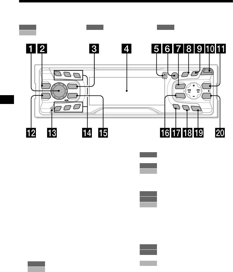
Location of controls
Refer to the pages listed for details.
TAPE RADIO MENU
: During tape playback : During radio reception : During menu mode
CD/MD
: During CD/MD playback (optional) (XR-CA600X/CA600V/CA600 only)
PTY
1
2
3
D
S
S
C
R
O
LL
O
P
E
N
REP
DISPLAY
I
S
C
/
P
R
E
S
E
D
T
MBP
SOURCE
MENU
LIST
SEEKSEEK
EQ 7
MODE
SOUND
ENTER
SHUF
5
6
AF
4
TA
O
FF
XR-CA600X/CA600V/CA600
a Volume control dial 13
n Number buttons
b MBP button 19
TAPE
1
c SOURCE (Power on/Tape/Radio/CD*
/
(3) REP 9
1
MD*
) button 5, 9, 10, 11, 13, 19, 20,
RADIO
10, 11, 13, 14
CD/MD
22
(3) REP 21
d Display window
(6) SHUF 21
e Z (eject) button (located on the front side
o MODE (o) button
of the unit, behind the front panel) 9
TAPE
9
f Receptor for the card remote
RADIO
10, 11, 13
commander
CD/MD
20, 22
g MENU button 8, 9, 10, 14, 15, 18, 19,
p SOUND button 17, 19
20, 22, 23, 24
q AF button 12, 14
h DISPLAY/PTY (display mode change/
r TA button 13, 14
1
programme type) button*
12, 15, 21,
2
s OFF (Stop/Power off) button*
5, 7, 9,
22
20
1
i SCROLL button*
21
t ENTER button
j OPEN button 7, 9
RADIO
11, 14
k XR-CA600X/CA600V/CA600:
MENU
8, 9, 10, 15, 18, 19, 20, 22, 23,
LIST button
24
RADIO
11
CD/MD
22, 23
CD/MD
22, 23
*1 XR-CA600X/CA600V/CA600 only
XR-L500X/L500V/L500:
*2 Warning when installing in a car without
PTY/DSPL button 12, 15
an ACC (accessory) position on the
l EQ7 button 19
ignition switch
m RESET button (located on the front side of
After turning off the ignition, be sure to press
the unit, behind the front panel) 7
(OFF) on the unit for 2 seconds to turn off
the clock display.
Otherwise, the clock display does not turn off
and this causes battery drain.
4
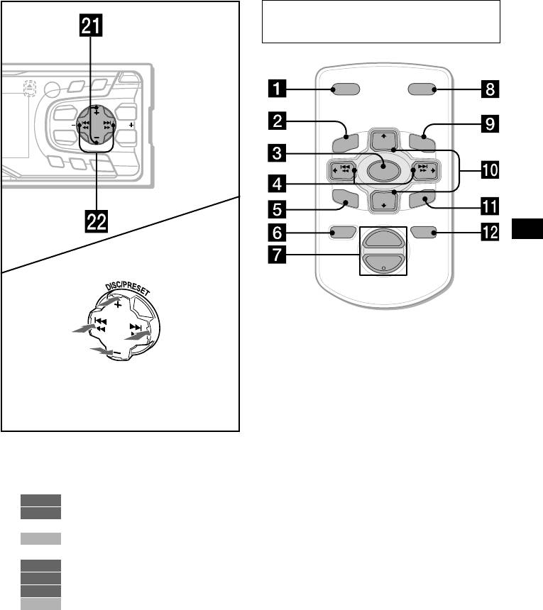
Card remote commander RM-X114
(optional)
PTY
D
S
O
P
EN
DSPL MODE
DISPLAY
SC
RO
LL
I
S
C
/
P
R
E
S
E
D
T
MENU
LIST
SEEKSEEK
PRESET
+
SOUND
ENTER
DISC
+
LIST
MENU
AF
TA
O
FF
SOURCE
SEEK
–
SEEK
+
SOUND
DISC
–
R
EN
TE
PRESET –
ATTOFF
+
VOL
(DISC/PRESET)/(PRESET)
–
(+): to select upwards
(SEEK)
(SEEK)
(–): to select
(+): to select
leftwards/
rightwards/
.
>
The corresponding buttons of the card
remote commander control the same
(DISC/PRESET)/(PRESET)
functions as those on this unit.
(–): to select downwards
a DSPL button
In menu mode, the currently selectable button (s)
b MENU button
of these four are indicated with a “ M” in the display.
c SOURCE button
d SEEK (</,) buttons
u XR-CA600X/CA600V/CA600:
e SOUND button
DISC/PRESET buttons (+/–)
f OFF button
XR-L500X/L500V/L500:
g VOL (–/+) buttons
PRESET buttons (+/–)
h MODE button
RADIO
10, 11, 15,
3
i LIST button*
MENU
8, 9, 10, 14, 15, 18, 19, 20, 22,
3
j DISC*
/PRESET(M/m) buttons
23, 24
k ENTER button
CD/MD
20, 22, 23
v SEEK buttons (–/+)
l ATT button
TAPE
9
RADIO
10, 11, 13
*3 Not available for XR-L500X/L500V/L500
MENU
8, 9, 15, 17, 18, 19, 20, 24
Note
CD/MD
20, 22, 23
If the units is turned off by pressing (OFF) for 2
seconds, it cannot be operated with the card remote
commander unless (SOURCE) on the unit is pressed,
or a cassette is inserted to activate the unit first.
Tip
Refer to “Replacing the lithium battery” for details on
how to replace the batteries (page 25).
5
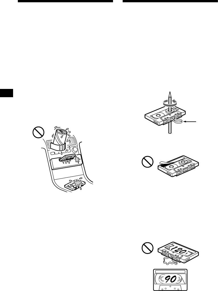
Precautions
Notes on Cassettes
• If your car was parked in direct sunlight, allow
Cassette care
the unit to cool off before operating it.
• Do not touch the tape surface of a cassette, as
• If no power is being supplied to the unit, check
any dirt or dust will contaminate the heads.
the connections first. If everything is in order,
• Keep cassettes away from equipment with
check the fuse.
built-in magnets such as speakers and
• If no sound comes from the speakers of a two—
amplifiers, as erasure or distortion on the
speaker system, set the fader control to the
recorded tape could occur.
centre position.
• Do not expose cassettes to direct sunlight,
• When a tape is played back for a long period,
extremely cold temperatures, or moisture.
the cassette may become warm because of the
• Slack in the tape may cause the tape to be
built-in power amplifier. However, this is not a
caught in the machine. Before you insert the
sign of malfunction.
tape, use a pencil or similar object to turn the
reel and take up any slack.
If you have any questions or problems
concerning your unit that are not covered in this
manual, please consult your nearest Sony dealer.
To maintain high quality sound
Be careful not to splash juice or other soft drinks
onto the unit or tapes.
Slack
• Distorted cassettes and loose labels can cause
problems when inserting or ejecting tapes.
Remove or replace loose labels.
• The sound may become distorted while playing
the cassette. The cassette player head should be
cleaned after each 50 hours of use.
The use of cassettes longer than 90 minutes
is not recommended except for long
continuous play
The tape used for these cassettes is very thin and
tends to stretch easily.
Frequent playing and stopping of these tapes
may cause them to become entangled in the
cassette deck mechanism.
6
Detaching the front panel
Getting Started
You can detach the front panel of this unit to
protect the unit from being stolen.
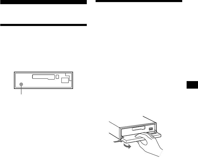
Resetting the unit
Caution alarm
If you turn the ignition switch to the OFF
Before operating the unit for the first time or
position without removing the front panel, the
after replacing the car battery, you must reset the
caution alarm will beep for a few seconds.
unit.
If you connect an optional amplifier and do not
Remove the front panel and press the RESET
use the built-in amplifier, the beep sound will be
button with a pointed object, such as a ballpoint
deactivated.
pen.
1 Press (OFF)*.
Tape playback or radio reception stops (the
key illumination and display remain on).
* If your car has no ACC position on the ignition
switch, be sure to turn the unit off by pressing
(OFF) for 2 seconds to avoid car battery drain.
RESET button
2 Press ( OPEN), then slide the front
Note
panel to the right, and gently pull out
Pressing the RESET button will erase the clock setting
the left end of the front panel.
and some stored contents.
1
2
Notes
• If you detach the panel while the unit is still turned
on, the power will turn off automatically to prevent
the speakers from being damaged.
• Do not drop or put excessive pressure on the front
panel and its display window.
• Do not subject the front panel to heat/high
temperature or moisture. Avoid leaving it in parked
cars or on dashboards/rear trays.
Tip
When carrying the front panel with you, use the
supplied front panel case.
continue to next page t
7
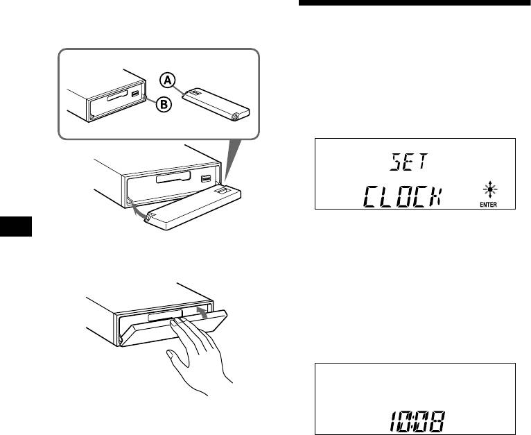
Attaching the front panel
Place hole A of the front panel onto the spindle
Setting the clock
B on the unit, then lightly push the left side in.
The clock uses a 24-hour digital indication.
Example: To set the clock to 10:08
1 Press (MENU), then press either side
of (DISC/PRESET) or (PRESET)
repeatedly until “CLOCK” appears.
1Press (ENTER).
The hour indication flashes.
2Press either side of (DISC/PRESET)
x
or (PRESET) to set the hour.
3Press the (+) side of (SEEK).
The minute indication flashes.
4Press either side of (DISC/PRESET)
or (PRESET) to set the minute.
2 Press (ENTER).
Note
Do not put anything on the inner surface of the front
panel.
The clock starts. After the clock setting is
completed, the display returns to normal play
mode.
Tips
• You can set the clock automatically with the RDS
feature (page 15).
• When D.INFO mode is set to ON, the time is always
displayed (page 18).
8
Playing a tape in various
Cassette Player
modes
You can play the tape in various modes:
Listening to a tape
• METAL lets you play a metal or CrO
2 tape.
• BL.SKP (Blank Skip) skips blanks longer than
8 seconds.
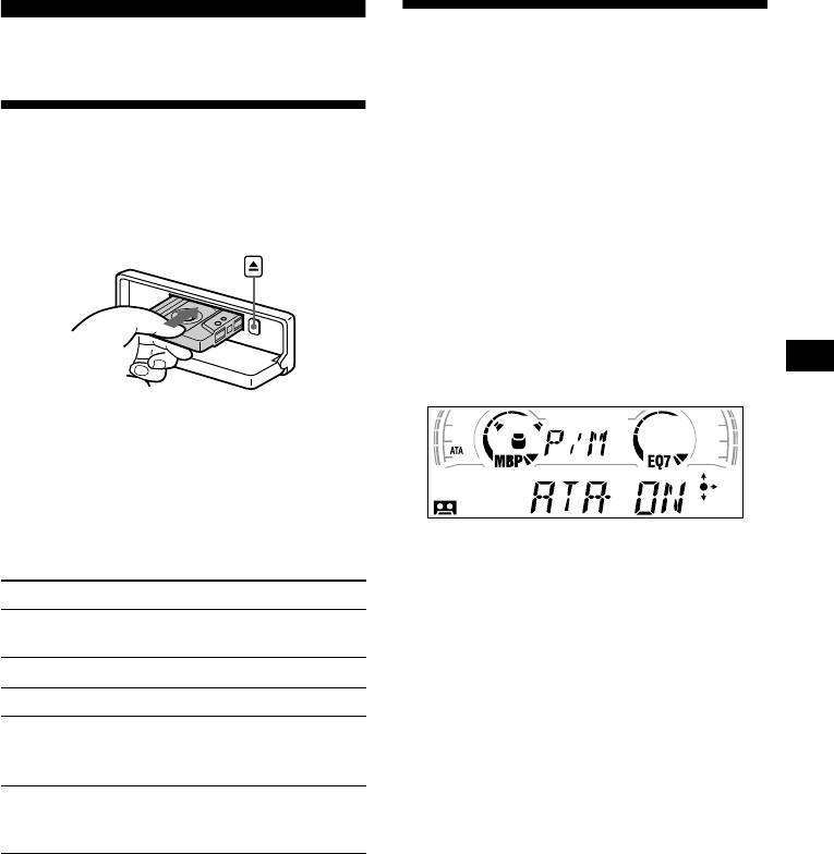
1 Press (OPEN) and insert a cassette.
• ATA (Automatic Tuner Activation) turns on the
Playback starts automatically.
tuner automatically when fast-winding the tape.
1 During tape playback, press (MENU).
2 Press either side of (DISC/PRESET) or
(PRESET) repeatedly until the desired
mode appears.
3 Press (+) side of (SEEK) to select
“ON.”
Example: ATA mode
2 Close the front panel.
If a cassette is already inserted, press (SOURCE)
repeatedly until “FORWARD” or “REVERSE”
appears to start playback.
FORWARD: The side facing up is played.
Play mode starts.
REVERSE: The side facing down is played.
4 Press (ENTER).
To Press
To return to normal playback mode, select
Change the tape’s
(MODE) (o)
“OFF” in step 3.
playback direction
Stop playback (OFF)
Playing tracks repeatedly
— Repeat Play
Eject the cassette (OPEN) then Z
Skip tracks
(SEEK) (./>)
During playback, press (3) (REP)
–Automatic
[once for each track]
repeatedly until “REP-ON” in the
Music Sensor
display appears.
Fast-forward/
(SEEK) (m/M)
To return to normal playback mode, select “REP-
reverse
[hold to desired point]
OFF.”
–Manual Search
Tip
During repeat playback, press (MODE). “REP”
Note
disappears from the display and repeat mode is
The AMS function may not work when:
cancelled.
– the blanks between tracks are shorter than 4
seconds.
– there is noise between tracks.
– there are long sections of low volume or quiet
sections.
9

Receiving the stored stations
Radio
1 Press (SOURCE) repeatedly to select
The unit can store up to 6 stations per band
the radio.
(FM1, FM2, FM3, MW, and LW).
2 Press (MODE) repeatedly to select the
Caution
band.
When tuning in stations while driving, use Best
3 Press the number button ((1) to (6))
Tuning Memory to prevent accidents.
on which the desired station is stored.
Tip
Press either side of (DISC/PRESET) or (PRESET) to
receive the stations in the order they are stored in the
Storing stations
memory (Preset Search function).
automatically
If preset tuning does not work
— Best Tuning Memory (BTM)
Press either side of (SEEK) to search
The unit selects the stations with the strongest
for the station (automatic tuning).
signals within the selected band, and stores them
Scanning stops when the unit receives a
in the order of their frequency.
station. Repeat until the desired station is
received.
1 Press (SOURCE) repeatedly to select
Tips
the radio.
• If automatic tuning stops too frequently, turn on the
2 Press (MODE) repeatedly to select the
Local Seek to limit seek to stations with stronger
band.
signals (see “Changing the sound and display
settings” on page 18).
3 Press (MENU), then press either side
• If you know the frequency of the station you want to
of (DISC/PRESET) or (PRESET)
listen to, press and hold either side of (SEEK) to
repeatedly until “BTM” appears.
locate the approximate frequency, then press
(SEEK) repeatedly to fine adjust to the desired
4 Press (ENTER).
frequency (manual tuning).
A beep sounds when the setting is stored.
Notes
If FM stereo reception is poor
• If only a few stations can be received due to weak
signals, some number buttons will retain their former
Select monaural reception mode.
settings.
(see “Changing the sound and display
• When a number is indicated in the display, the unit
settings” on page 18). The sound improves,
starts storing stations from the one currently
but becomes monaural (“ST” disappears).
displayed.
10
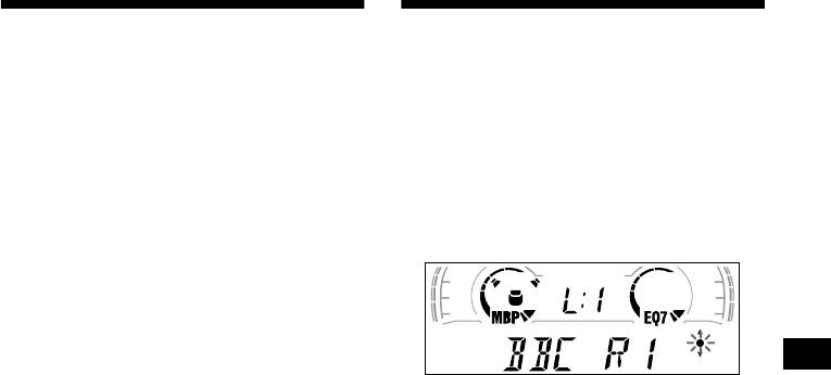
Storing only the desired
Tuning in a station through a
stations
list (XR-CA600X/CA600V/
CA600 only)
You can manually preset the desired stations on
any chosen number button.
— List-up
1 Press (SOURCE) repeatedly to select
1 During radio reception, press (LIST)
the radio.
momentarily.
2 Press (MODE) repeatedly to select the
The frequency or the name assigned to the
band.
station currently tuned in flashes.
3 Press either side of (SEEK) to tune in
the station that you want to store.
4 Press the desired number button ((1)
to (6)) for 2 seconds until “MEM”
appears.
The number button indication appears in the
display.
2 Press either side of (DISC/PRESET)
Note
repeatedly until you find the desired
If you try to store another station on the same number
station.
button, the previously stored station will be erased.
If no name is assigned to the selected station,
the frequency appears in the display.
3 Press (ENTER) to tune in the desired
station.
11
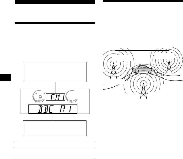
Automatic retuning for best
RDS
reception results
— AF function
Overview of RDS
The alternative frequencies (AF) function allows
the radio to always tune into the area’s strongest
signal for the station you are listening to.
FM stations with Radio Data System (RDS)
service send inaudible digital information along
Frequencies change automatically.
with the regular radio programme signal. For
example, one of the following will be displayed
upon receiving a station with RDS capability.
96.0 MHz
98.5 MHz
Displayable items
• Music source
• Clock
• Function
Station
102.5 MHz
1 Select an FM station (page 10).
2 Press (AF) repeatedly until “AF-ON”
appears.
The unit starts searching for an alternative
Displayable items
frequency with a stronger signal in the same
• Station name (frequency)
network.
• Programme type
If “NO AF” flashes, the currently tuned into
station does not have an alternative frequency.
Note
To Press
When there is no alternative frequency in the area or
Switch display
(DISPLAY/PTY) or
when you do not need to search for one, turn the AF
item
(PTY/DSPL)
function off by selecting “AF-OFF.”
RDS services
RDS data offers you other conveniences, such as:
• Automatic retuning of a programme, helpful
during long-distance drives. — AF t page 12
• Receiving traffic announcements, even
when enjoying another programme/source. —
TA t page 13
• Selecting stations by the type of programme
it broadcasts. — PTY t page 14
• Automatic clock time setting. — CT t page
15
Notes
• Depending on the country or region, not all of the
RDS functions are available.
• RDS may not work properly if the signal strength is
weak or if the station you are tuned to is not
transmitting RDS data.
12

For stations without alternative
frequencies
Receiving traffic
Press either side of (SEEK) while the
announcements
station name is flashing (within 8
seconds).
— TA/TP
The unit starts searching for another
By activating the Traffic Announcement (TA)
frequency with the same PI (Programme
and Traffic Programme (TP), you can
Identification) data (“PI SEEK” appears).
automatically tune in an FM station broadcasting
If the unit cannot find the same PI, the unit
traffic announcements. These settings function
returns to the previously selected frequency.
regardless of the current FM programme/source,
CD/MD; the unit switches back to the original
Staying with one regional programme
source when the bulletin is over.
When AF function is on: this unit’s factory-set
Press (TA) repeatedly until “TA—ON”
setting restricts reception to a specific region, so
appears.
you won’t be switched to another regional station
The unit starts searching for traffic
with a stronger frequency.
information stations.
If you leave this regional programme’s reception
“TP” indicates reception of such stations, and
area or would like to take advantage of the whole
“TA” flashes during an actual traffic
AF function, select “REG-OFF” from the MENU
announcement. The unit will continue
(page 18).
searching for stations available with TP if
Note
“NO TP” is indicated.
This function does not work in the United Kingdom
and in some other areas.
To cancel all traffic announcements, select “TA—
OFF.”
Local Link function
(United Kingdom only)
To Press
This function enables you to select other local
Cancel current
(TA)
stations in the area, even if they are not stored on
announcement
your number buttons.
1 Press a number button ((1) to (6))
Tip
You can also cancel the current announcement by
that has a local station stored on it.
pressing (SOURCE) or (MODE).
2 Within 5 seconds, press the number
button of the local station again.
Presetting the volume of traffic
3 Repeat this procedure until the
announcements
desired local station is received.
You can preset the volume level of the traffic
announcements so you won’t miss hearing them.
1 Turn the volume control dial to adjust
the desired volume level.
2 Press (TA) for 2 seconds.
“TA” appears and the setting is stored.
Receiving emergency announcements
If either AF or TA is on, the unit will switch to
emergency announcements, if one comes in
while listening to an FM station, a tape, or
optional CD/MD.
13

Presetting RDS stations with
Tuning in stations by
AF and TA setting
programme type
— PTY
When you preset RDS stations, the unit stores
each station’s AF/TA setting (on/off) as well as
You can tune in a station by selecting the type of
its frequency. You can select a different setting
programme you would like to listen to.
(for AF, TA, or both) for individual preset
stations, or the same setting for all preset
Programme types Display
stations. If you preset stations with “AF-ON” the
unit automatically stores stations with the
News NEWS
strongest radio signal.
Current Affairs AFFAIRS
Information INFO
Presetting the same setting for all
preset stations
Sports SPORT
Education EDUCATE
1 Select an FM band (page 10).
Drama DRAMA
2 Press (AF) and/or (TA) to select “AF—
Culture CULTURE
ON” and/or “TA—ON.”
Note that selecting “AF-OFF” or “TA—OFF”
Science SCIENCE
stores not only RDS stations, but also non-
Va ri ed VAR IE D
RDS stations.
Popular Music POP M
3 Press (MENU), then press either side
of (DISC/PRESET) or (PRESET)
Rock Music ROCK M
repeatedly until “BTM” appears.
Easy Listening EASY M
4 Press (ENTER) until “BTM” flashes.
Light Classical LIGHT M
Classical CLASSICS
Presetting different settings for each
preset station
Other Music Type OTHER M
Weather WEATHER
1 Select an FM band, and tune in the
desired station (page 11).
Finance FINANCE
Children’s Programmes CHILDREN
2 Press (AF) and/or (TA) to select “AF—
ON” and/or “TA—ON.”
Social Affairs SOCIAL A
3 Press the desired number button ((1)
Religion RELIGION
to (6)) until “MEM” appears.
Phone In PHONE IN
Repeat from step 1 to preset other stations.
Travel TRAVEL
Leisure LEISURE
Jazz Music JAZZ
Country Music COUNTRY
National Music NATION M
Oldies Music OLDIES
Folk Music FOLK M
Documentary DOCUMENT
Note
You cannot use this function in some countries where
no PTY (Programme Type selection) data is available.
14
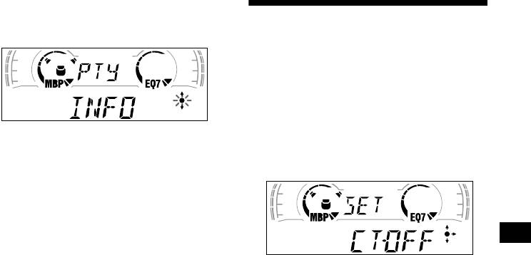
1 Press (DISPLAY/PTY) or (PTY/DSPL)
during FM reception until “PTY”
Setting the clock
appears.
automatically
— CT
The CT (Clock Time) data from the RDS
transmission sets the clock automatically.
1 During radio reception, press (MENU),
The current programme type name appears if
then press either side of
the station is transmitting the PTY data.
(DISC/PRESET) or (PRESET) repeatedly
“— — — — — — — —” appears if the received station is
until “CT-OFF” appears.
not an RDS station, or if the RDS data is not
received.
2 Press (DISC/PRESET ) or (PRESET)
repeatedly until the desired
programme type appears.
The programme types appear in the order
shown in the table.
“— — — — — — — —” appears if the programme type
2 Press the (+) side of (SEEK) repeatedly
is not specified in the RDS data.
until “CT-ON” appears.
The clock is set.
3 Press (ENTER).
The unit starts searching for a station
3 Press (ENTER) to return to the normal
broadcasting the selected programme type.
display.
To cancel the CT function, select “CT-OFF” in
step 2.
Notes
• The CT function may not work even though an RDS
station is being received.
• There might be a difference between the time set by
the CT function and the actual time.
15
*1 XR-CA600X/CA600V/CA600 only
*2 Only if the corresponding optional equipment is
connected (XR-CA600X/CA600V/CA600 only).
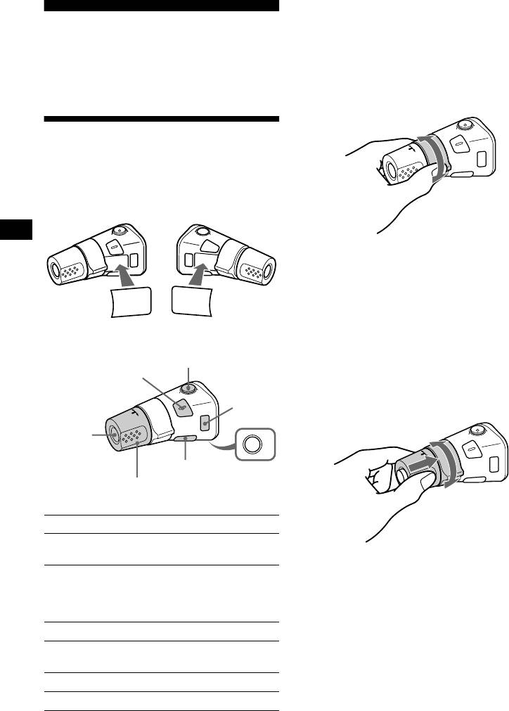
Other Functions
*3 If your car has no ACC (accessory) position on the
ignition key switch, be sure to press (OFF) for 2
You can also control the unit (and optional CD/
seconds to turn off the clock indication after turning
1
off the ignition.
MD units*
) with a rotary commander
(optional).
By rotating the control
Using the rotary commander
First, attach the appropriate label depending on
how you want to mount the rotary commander.
The rotary commander works by pressing
SEEK/AMS
buttons and/or rotating controls.
control
Rotate and release to:
– Locate the beginning of tracks on the tape.
– Tune in stations automatically.
2
– Skip tracks on the disc.*
SOUND
DSPL
MODE
MODE
Rotate, hold, and release to:
DSPL
SOUND
– Fast-wind the tape.
– Find a station manually.
2
– Fast-forward/reverse a track.*
By pressing buttons
Tip
(ATT)
To start playback while fast-winding the tape, press
(SOUND)
(MODE).
(MODE)
By pushing in and rotating the control
(SOURCE)
OFF
(DSPL)
(OFF)
Rotate the VOL control
to adjust the volume.
PRESET/
DISC control
Press To
Change source
(SOURCE)
2
2
(radio/CD*
/MD*
/Tape)
Push in and rotate the control to:
– Receive preset stations.
Change operation
2
2
– Change the disc*
.
(radio band/CD unit*
/MD
(MODE)
2
unit*
/tape playback
direction)
(ATT) Attenuate sound
Stop playback or radio
3
(OFF)*
reception
(SOUND) Adjust the sound menu
(DSPL) Change the display item
16
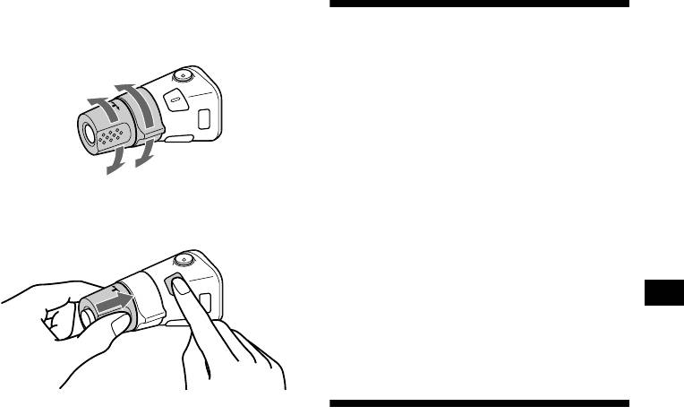
Changing the operative direction
The operative direction of controls is factory-set
Adjusting the sound
as shown below.
characteristics
To increase
You can adjust the bass, treble, balance, and
fader.
The bass and treble levels can be stored
independently for each source.
To decrease
1 Select the item you want to adjust by
pressing (SOUND) repeatedly.
If you need to mount the rotary commander on
Each time you press (SOUND), the item
the right hand side of the steering column, you
changes as follows:
can reverse the operative direction.
BAS (bass) t TRE (treble) t BAL (left-
right)
t FAD (front-rear)
2 Adjust the selected item by pressing
either side of (SEEK).
When adjusting with the rotary commander,
press (SOUND) and rotate the VOL control.
Note
Adjust within 3 seconds after selecting the item.
Press (SOUND) for 2 seconds while
Quickly attenuating the
pushing the VOL control.
sound
Tip
You can also change the operative direction of these
(With the rotary commander or the card
controls with the unit (see “Changing the sound and
remote commander)
display settings” on page 18).
Press (ATT) on the rotary commander
or card remote commander.
After “ATT- O N” momentarily appears, the
“AT T” appears in the display.
To restore the previous volume level, press
(ATT) again.
Tip
When the interface cable of a car telephone is
connected to the ATT lead, the unit decreases the
volume automatically when a telephone call comes in
(Telephone ATT function).
17

P/M (Play Mode)
Changing the sound and
• LOCAL-ON/OFF (Local seek mode) (page 10)
– Select “ON” to only tune into stations with
display settings
stronger signals.
• MONO-ON/OFF (Monaural mode) (page 10)
— Menu
– Select “ON” to hear FM stereo broadcast in
The following items can be set:
monaural. Select “OFF” to return to normal
mode.
• REG-ON/OFF (Regional) (page 13)
SET (Set Up)
• CLOCK (page 
1 Press (MENU).
• CT (Clock Time) (page 15)
To set A.SCRL, press (MENU) during CD/
• BEEP — to turn the beeps on or off.
MD Playback.
• RM (Rotary Commander) — to change the
operative direction of the controls of the rotary
2 Press either side of (DISC/PRESET) or
commander.
(PRESET) repeatedly until the desired
– Select “NORM” to use the rotary commander
item appears.
as the factory-set position.
3 Press the (+) side of (SEEK) to select
– Select “REV” when you mount the rotary
the desired setting (Example: ON or
commander on the right side of the steering
OFF).
column.
4 Press (ENTER).
After the mode setting is completed, the
DSPL (Display)
display returns to normal play mode.
• D.INFO (Dual Information) — to display the
clock and the play mode at the same time (ON).
Note
• AMBER/GREEN — to change the
The displayed item will differ depending on the source.
illumination colour to amber or green (XR-
Tip
CA600/L500 only).
You can easily switch among categories (“SET,”
• DIM (Dimmer) — to change the brightness of
“DSPL,” “SND,” “P/M,” and “EDIT”) by pressing either
the display (XR-CA600V/L500V only).
side of (DISC/PRESET) or (PRESET) for 2 seconds.
– Select “ON” to dim the display.
– Select “OFF” to deactivate the Dimmer.
• M.DSPL (Motion Display) — to select the
Motion Display mode from “1,” “2,” and
“OFF.”
– Select “1” to show decoration lines in the
display and activate Demo display.
– Select “2” to show decoration lines in the
display and deactivate Demo display.
– Select “OFF” to deactivate the Motion
Display.
• A.SCRL (Auto Scroll)*
– Select “ON” to scroll all automatically
displayed names exceeding 8 characters.
– When Auto scroll is set to off and the disc/
track name is changed, the disc/track name
does not scroll.
* When no CD or MD is playing, this item will not
appear. (XR-CA600X/CA600V/CA600 only)
SND (Sound)
• LOUD (Loudness) — to enjoy bass and treble
even at low volumes. The bass and treble will
be reinforced (XR-CA600V/CA600/L500V/
L500 only).
18
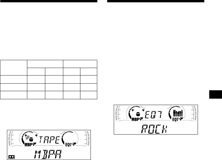
Selecting the sound position
Setting the equalizer
— My Best sound Position (MBP)
You can select an equalizer curve for seven
When you drive without passengers, you can
music types (XPLOD, VOCAL, CLUB, JAZZ,
enjoy the most comfortable sound environment
NEW AGE, ROCK, CUSTOM, and OFF
with “My Best sound Position.”
(equalizer OFF)).
“My Best sound Position” has two presets, which
You can store and adjust the equalizer settings
adjust the sound level of balance and fader. You
for frequency and level.
can select one very easily with the MBP button.
Selecting the equalizer curve
Balance Level Fader Level
Display
window
1 Press (SOURCE) to select a source
Right Left Front Rear
(radio, CD, MD, or tape).
MBP-A
– 4dB 0 0 – 4dB
2 Press (EQ7) repeatedly until the
MBP-B 0 – 4dB 0 – 4dB
desired equalizer curve.
Each time you press (EQ7), the item
MBP-OFF
0000
changes.
Press (MBP) repeatedly for the desired
listening position.
The mode of “My Best sound Position” is
shown in the display in order of the table.
To cancel the equalizing effect, select “OFF.”
After 3 seconds, the display returns to the
normal playback mode.
After one second, the display goes back to the
Adjusting the equalizer curve
normal playback mode.
If you want to adjust the sound level of
1 Press (MENU).
balance and fader more precisely, you can do
it using the (SOUND) button (see “Adjusting
2 Press either side of (DISC/PRESET) or
the sound characteristics” on page 17).
(PRESET) repeatedly until “EQ7
Notes
TUNE” appears, then press (ENTER).
• When the BAL (balance) or FAD (fader) in “Adjusting
3 Press either side of (SEEK) to select
the sound characteristics” (page 17) is adjusted, the
the desired equalizer curve, then
MBP setting returns to OFF.
• When MBP is set to OFF, the BAL and FAD setting is
press (ENTER).
activated.
Each time you press (SEEK), the item
changes.
continue to next page t
19
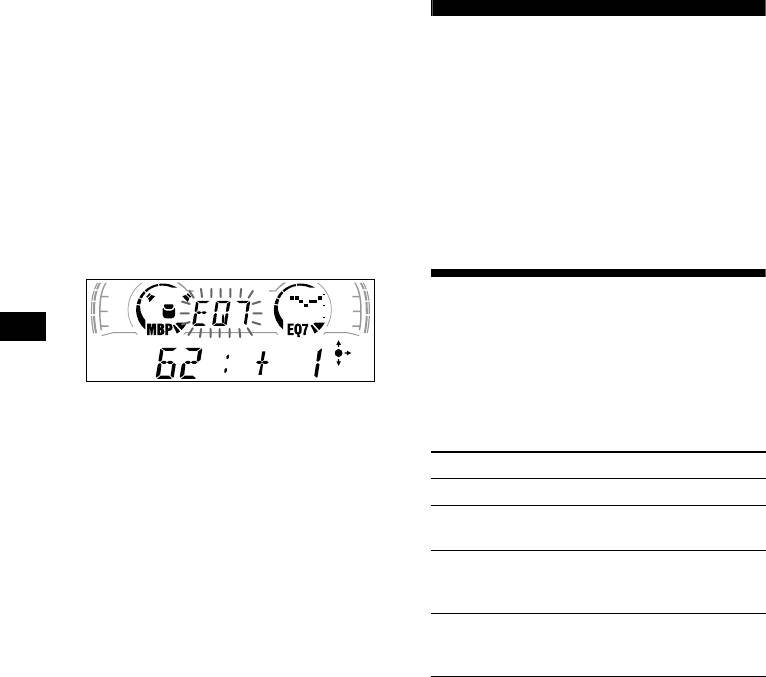
4 Select the desired frequency and level.
1 Press either side of (SEEK) to select
CD/MD Unit (optional)
the desired frequency.
Each time you press (SEEK), the
(XR-CA600X/CA600V/CA600
frequency changes.
only)
62 (Hz) y 157 (Hz) y 396 (Hz) y
1k (Hz) y 2.5k (Hz) y 6.3k (Hz) y
16k (Hz)
This unit can control external CD/MD units.
If you connect an optional CD unit with the CD
2 Press either side of ( DISC/PRESET )
TEXT function and the custom file function, the
or (PRESET) to adjust the desired
CD TEXT information will appear in the display
volume level.
when you play a CD TEXT disc.
The volume level is adjustable by 1 dB
steps from –10 dB to +10 dB.
Playing a CD or MD
1 Press (SOURCE) repeatedly to select
“CD” or “MD.”
2 Press (MODE) repeatedly until the
To restore the factory-set equalizer curve,
desired unit appears.
press (ENTER) for 2 seconds.
CD/MD playback starts.
5 Press (MENU) twice.
When the effect setting is complete, the
To Press
normal playback mode appears.
Stop playback (OFF)
Skip discs
(DISC/PRESET) (+/–)
–Disc selection
Skip tracks
(SEEK) (./>)
–Automatic
[once for each track]
Music Sensor
Fast-forward/
(SEEK) (m/M)
reverse
[hold to desired point]
–Manual Search
20
Аннотация для Автомагнитолы Sony XR-CA600 в формате PDF
Топ 10 инструкций
Другие инструкции
-
Contents
-
Table of Contents
-
Bookmarks
Quick Links
CDX-CA600/CA600X
SERVICE MANUAL
Ver 1.0 2001. 12
• The tuner and CD sections have no adjustments.
CD player section
Signal-to-noise ratio
90 dB
Frequency response
10 – 20,000 Hz
Wow and flutter
Below measurable limit
Tuner section
FM
Tuning range
87.5 – 108.0 MHz
Aerial terminal
External aerial connector
Intermediate frequency 10.7 MHz/450 kHz
Usable sensitivity
8 dBf
Selectivity
75 dB at 400 kHz
Signal-to-noise ratio
66 dB (stereo),
72 dB (mono)
Harmonic distortion at 1 kHz
0.6% (stereo),
0.3% (mono)
Separation
35 dB at 1 kHz
Frequency response
30 – 15,000 Hz
MW/LW
Tuning range
MW : 531 – 1,602 kHz
LW : 153 – 279 kHz
Aerial terminal
External aerial connector
Intermediate frequency 10.7 MHz/450 kHz
Sensitivity
MW : 30 µV
LW : 40 µV
Sony Corporation
9-873-434-01
2001L0400-1
e Vehicle Company
© 2001. 12
Published by Sony Engineering Corporation
Photo: CDX-CA600X
Model Name Using Similar Mechanism
CD Drive Mechanism Type
Optical Pick-up Name
SPECIFICATIONS
Power amplifier section
Outputs
Speaker impedance
Maximum power output 50 W × 4 (at 4 ohms)
General
Outputs
Input
Tone controls
Power requirements
Dimensions
Mounting dimensions
Mass
Supplied accessories
Note
This unit cannot be connected to a digital preamplifier or an equalizer.
Design and specifications are subject to change without
notice.
FM/MW/LW COMPACT DISC PLAYER
AEP Model
UK Model
CDX-CA600/CA600X
E Model
CDX-CA600X
CDX-L300/L460X
MG-393XA-121//K
KSS-720A
Speaker outputs
(sure seal connectors)
4 – 8 ohms
Power aerial relay control lead
Telephone ATT control lead
Bass ±9 dB at 100 Hz
Treble ±9 dB at 10 kHz
12 V DC car battery
(negative earth)
Approx. 178 × 50 × 177 mm
(w/h/d)
Approx. 182 × 53 × 161 mm
(w/h/d)
Approx. 1.2 kg
Parts for installation and connections (1 set)
Front panel case (1)
Card remote commander RM-X115 (E model)
1