-
Contents
-
Table of Contents
-
Troubleshooting
-
Bookmarks
Quick Links
E-830-100-11 (1)
Wireless Network
Connection
Setup Guide
Rev. 1.00
Software Version 3.0
PXW-Z280/Z190
© 2019 Sony Imaging Products & Solutions Inc.
Related Manuals for Sony PXW-Z280
Summary of Contents for Sony PXW-Z280
-
Page 1
E-830-100-11 (1) Wireless Network Connection Setup Guide Rev. 1.00 Software Version 3.0 PXW-Z280/Z190 © 2019 Sony Imaging Products & Solutions Inc. -
Page 2: Table Of Contents
Table of Contents Chapter 1 Overview Chapter 2 Use Cases 2.1. Live Workflow in XDCAM air Example Use Cases ….6 2.1.1. Live Streaming …………..7 2.1.2. Intercom Operation…………7 2.1.3. Camera Remote Control ……….8 2.2. File Workflow in XDCAM air Example Use Cases….9 2.2.1.
-
Page 3
5.3.3. Wired LAN …………..25 5.3.4. Networks Combinations ……….26 5.4. Network Client Mode Settings ……… 28 5.5. Network Communication Test………. 29 5.5.1. 4G/LTE USB Modem …………29 5.5.2. Wireless LAN …………..29 5.5.3. Wired LAN …………..30 5.6. Network Client Mode Communication Test…….31 5.6.1. -
Page 4
Chapter 11 Setup for “Upload to FTP Server” 11.1. Camcorder Settings …………40 11.2. FTP Server Settings…………40 11.3. FTP Server Communication Test ……..40 Chapter 12 Troubleshooting 12.1. Network…………….41 12.1.1. 4G/LTE USB Modem…………41 12.1.2. Wireless LAN …………..42 12.1.3. -
Page 5
This Setup Guide describes the preparation for the use cases listed on the following pages, and the daily checks required when using the Sony PXW-Z280/Z190 camcorder. Common items for use cases are listed in chapters 3 and 5, and individual items for each use case are listed separately in chapters 4 and 6 to 11. -
Page 6: Chapter 2 Use Cases
Live Streaming e.g. PXW-X400 XDCAM air QoS Stream SNS output Intercom Operation SDI output Intercom Handheld Camcorders e.g. PXW-Z280/Z190 Camera Remote Control Remote Control Camera Operators Studio Operators in the field in the station *1: Shoulder camcorder does not supported.
-
Page 7: Live Streaming
Shoulder Camcorders e.g. PXW-X400 QoS Stream SNS output Cloud Services Handheld Camcorders i.e. XDCAM air e.g. PXW-Z280/Z190 QoS Stream SDI output Camera Operators Studio Operators in the field in the station Live streaming with QoS control is supported with XDCAM air or Network RX Station.
-
Page 8: Camera Remote Control
CCM (XDCAM air / Network RX Station) 2.1.3. Camera Remote Control Shoulder Camcorders e.g. PXW-X400 XDCAM air Remote Control Handheld Camcorders e.g. PXW-Z280/Z190 *) This feature is most likely used in “One-man Reporter” case. Camera Operators Studio Operators in the field in the station Supported camera remote control functions •…
-
Page 9: File Workflow In Xdcam Air Example Use Cases
File Naming News Story XDCAM air Proxy Auto-Upload Proxy Clip upload Preview & Select Clips Handheld Camcorders e.g. PXW-Z280/Z190 Rough-cut Edit Upload to FTP server Hi-Res Clip upload FTP Server Select Clips / Select a (3rd party) part of clips (Partial…
-
Page 10: Proxy Auto Upload
XDCAM air Pre-configure the destination of storage space to where camera upload Proxy clips automatically. Handheld Camcorders e.g. PXW-Z280/Z190 Upload Proxy Clips automatically to FTP server, Cloud Services like FTP Server XDCAM air, Ci Media Cloud. (3rd party)
-
Page 11
Setup checkpoints TX side Camcorder Settings: Remote File Transfer Related Equipment (Wireless LAN/LTE/Wired LAN) RX side CCM File List UI Proxy Playback and Proxy File Pull CCM Cut Edit using Proxy Request to camcorder for Partial File Transfer… -
Page 12: Chapter 3 Preparation
3.1.1. 4G/LTE USB Modem The supported USB modem models vary depending on the country or region. For details, contact a Sony professional sales representative. “Single Link” and “Dual Link” are both supported for the Live Streaming Operation use case. “Single Link” uses one network, while “Dual Link” uses multiple networks for streaming.
-
Page 13: Wireless Lan
3.1.2. Wireless LAN Check the wireless LAN router’s settings before configuring the camcorder’s network settings. The following information is required. • SSID and password • Whether the IP address is set by DHCP or manually • Whether DNS is set automatically or manually 3.1.3.
-
Page 14: Network Client Mode (Ncm)
3.2. Network Client Mode (NCM) Check the XDCAM air or Network RX Station settings information before configuring the camcorder’s network client mode settings. The following information is required. • URL or IP address for Connection Control Manager (CCM) • Port number •…
-
Page 15: Usb Headset Connection For Intercom
3.4. USB Headset Connection for Intercom Connect a USB headset to the USB 3.0 (HOST) connector (A) on the rear of the unit. A USB headset cannot be connected using a USB hub.
-
Page 16: Chapter 4 Setup To-Do List
Setup To-Do List Chapter This section describes the “To-Do List” for each use case. The Network settings and Network Client Mode settings are common to each use case. 4.1. To-Do List for “Live Streaming” Table 1. To-Do List for “Live Streaming” 5.2.
-
Page 17: To-Do List For «Camera Remote Control
4.3. To-Do List for “Camera Remote Control” Table 3. To-Do List for “Camera Remote Control” 5.2. Assembling 5.3. Network Settings 5.4. Network Client Mode Settings 5.5. Network Communication Test 5.6. Network Client Mode Communication Test 8.1. Camcorder Settings 8.2. Camera Remote Test 4.4.
-
Page 18: To-Do List For «Upload To Ftp Server
4.6. To-Do List for “Upload to FTP Server” Table 6. To-Do List for “Upload to FTP Server” 5.2. Assembling 5.3. Network Settings 5.4. Network Client Mode Settings 5.5. Network Communication Test 5.6. Network Client Mode Communication Test 11.1. Camcorder Settings 11.2.
-
Page 19: Chapter 5 Common Setup
Common Setup Chapter 5.1. Equipment for Wireless Solution Table 7. Equipment List USB modem CBK-DL1 5.2. Assembling See the Operating Instructions for the PXW-Z280/PXW-Z190.
-
Page 20: Network Settings
5.3. Network Settings Select Network > Access Authentication in the setup menu, and set User Name and Password. For security, set the user name and password by yourself. It is recommended that you set a password with a sufficiently long character string that is hard to guess by others, and that you store it safely.
-
Page 21: Wireless Lan
The 3G/4G icon appears on the LCD panel. “12.1.1. 4G/LTE USB Modem” If you experience any difficulty, see in the Troubleshooting section. 5.3.2. Wireless LAN 5.3.2.1. Wireless LAN Station mode settings Select Network > Wireless LAN in the setup menu, and set Setting to Station Mode. Note The conditions under which a wireless LAN can be used are determined by the combination with other networks and video outputs (SDI/HDMI/VIDEO).
-
Page 22
Select Network > ST Mode Settings > Scan Networks in the setup menu, then scan for available networks. The device scans for networks and displays a list of detected SSIDs. Select an SSID. A password setting dialog appears. Enter the password for the SSID, select the Done button. and press the SEL/SET dial or SET button. Check the DHCP and DNS settings, select the Connect button, and press the SEL/SET dial or SET button. -
Page 23
“12.1.2. Wireless LAN” If you experience any difficulty, see in the Troubleshooting section. To set the SSID and other settings manually Select Network > ST Mode Settings > Manual Register in the setup menu, and enter the SSID, password and other settings. Select the Connect button on the menu screen, and press the SEL/SET dial or SET button. -
Page 24
5.3.2.2. Wireless LAN Access Point mode settings Select Network > Wireless LAN in the setup menu, and set Setting to Access Point Mode. Network > AP Mode Settings > Camera SSID & Password in the setup menu becomes enabled. Check the SSID and password. Other wireless LAN devices can now be connected to the camcorder using the SSID and password. -
Page 25: Wired Lan
When the connection is successful, the following screen appears in the web browser. 5.3.3. Wired LAN Select Network > Wired LAN in the setup menu, and set Setting to On. Note The conditions under which a wired LAN can be used are determined by the combination with other networks and video outputs (SDI/HDMI/VIDEO).
-
Page 26: Networks Combinations
Select Network > Wired LAN > Detail Settings in the setup menu. Select whether to obtain an IP address automatically via DHCP or set the IP address manually, and select whether to obtain DNS automatically or set DNS manually. Select the Set button on the menu screen, and press the SEL/SET dial or SET button. When the connection is successful, the LAN icon appears.
-
Page 27
Modem1 Modem2 Wired LAN Wireless LAN Operation Dual Link: Uses Wired LAN and Wireless LAN. Single Link: Uses Wired LAN. Dual Link cannot be used. Single Link: Uses Wired LAN. Dual Link cannot be used. Single Link: Uses Wireless LAN. Network function is disabled. -
Page 28: Network Client Mode Settings
5.4. Network Client Mode Settings Check that the Date Time settings in System > Clock Set are correct before configuring the Network Client Mode settings. Network Client Mode presets can be configured in NCM Settings 1 to 3. The following procedure describes how to set NCM Settings1 as an example. Select Network >…
-
Page 29: Network Communication Test
5.5. Network Communication Test 5.5.1. 4G/LTE USB Modem After attaching and configuring a 4G/LTE USB modem, the next step is test for network communication via the USB modem. “3.1.1. 4G/LTE USB It is recommended that you test the USB modem using a computer beforehand (see Modem”…
-
Page 30: Wired Lan
5.5.3. Wired LAN After configuring a wired LAN, the next step is to test for network communication via the wired LAN. Turn on the camcorder, and check that the LAN status indicator appears on the camcorder LCD screen. When the network connection is working correctly, the LAN status indicator appears. “12.1.3.
-
Page 31: Network Client Mode Communication Test
5.6. Network Client Mode Communication Test After the network communication test is successful, the next step is to test Network Client Mode. Select Network > Network Client Mode > NCM Settings Select in the setup menu, and select NCM Settings1. Note NCM Settings1 is used as an example.
-
Page 32: Network Rx Station
After activation, the icon appears on the camcorder LCD screen and thumbnails appear on the CCM UI screen. “12.2. Network Client Mode” If you experience any difficulty, see in the Troubleshooting section. 5.6.2. Network RX Station Select Network > Network Client Mode in the setup menu, and set Setting to On. Start communication with the CCM of Network RX Station.
-
Page 33: Chapter 6 Setup For «Live Streaming
Setup for “Live Streaming” Chapter 6.1. Camcorder Settings Because of some system restrictions, “Live Streaming” is not available in the following cases. Check the camcorder settings. – When System > Rec Format > Codec is set to DVCAM(MXF) in the setup menu –…
-
Page 34: Chapter 7 Setup For «Intercom Operation
Setup for “Intercom Operation” Chapter 7.1. Camcorder Settings The intercom function is not available in following cases. – When Camera > Focus > Face Detection AF is set to Face Only AF or Face Priority AF in the setup menu –…
-
Page 35: Chapter 8 Setup For «Camera Remote Control
Setup for “Camera Remote Control” Chapter 8.1. Camcorder Settings For camera remote operation, set Camera Control to Enable in the Network Client Mode settings. “5.4. Network Client Mode Settings” For details, see 8.2. Camera Remote Test After checking that Network Client Mode communication is successful, you can check camera remote operation.
-
Page 36: Chapter 9 Setup For «File Naming Using Planning Metadata
Setup for “File Naming using Planning Metadata” Chapter 9.1. Camcorder Settings For setting file names using planning metadata, the following settings must be configured on the camcorder. Select Media > Clip Naming in the setup menu, and set Auto Naming to Plan. Select LCD/VF >…
-
Page 37: Chapter 10 Setup For «Proxy Auto Upload
Setup for “Proxy Auto Upload” Chapter 10.1. Camcorder Settings For automatically uploading proxy files, the following setting must be configured on the camcorder. Select Network > File Transfer in the setup menu, and set Auto Upload (Proxy) to On. When Auto Upload (Proxy) is set to On, the uploading of proxy files to a destination server occurs after proxy recording ends.
-
Page 38: Ftp Server Communication Test
10.3. FTP Server Communication Test Check communication with the FTP server. 10.3.1. Checking Operation using the Menu Select Thumbnail > Transfer Clip (Proxy) > Select Clip in the setup menu. Select a clip, and start the file transfer. Select Network > File Transfer > View Job List in the setup menu. Check that the specified clip is being transferred.
-
Page 39
Select clips and click the Transfer button on the web page. The Transfer Confirm dialog appears. Select Upload Server, enter the destination directory, and click the Transfer button. Display the Job List screen. Status: “Waiting” indicates that file transfer is pending. If a problem arises, an error message is displayed. -
Page 40: Chapter 11 Setup For «Upload To Ftp Server
Setup for “Upload to FTP Server” Chapter 11.1. Camcorder Settings No specific settings need to be configured on the camcorder. 11.2. FTP Server Settings “10.2. FTP Server Settings” 11.3. FTP Server Communication Test “10.3. FTP Server Communication Test”…
-
Page 41: Chapter 12 Troubleshooting
Troubleshooting Chapter 12.1. Network 12.1.1. 4G/LTE USB Modem Problem: Cannot connect to network via modem Display or Message Reason & Solution 3G/4Gx icon is displayed Cannot connect to carrier communication network. “3.1.1. 4G/LTE USB Modem” Check that there is a SIM in the modem (see Check that there is a carrier radio wave signal.
-
Page 42: Wireless Lan
12.1.2. Wireless LAN Problem: Cannot connect to network via Wi-Fi Display or Message Reason & Solution Only lower left dot of wireless SSID or Key (Password) is incorrect. “5.3.2. Wireless LAN” LAN icon is displayed (See Searching for an access point. Check the Wi-Fi access point.
-
Page 43: Network Client Mode
12.2. Network Client Mode Problem: Cannot connect to CCM Display or Message Reason & Solution NCM icon is displayed Camcorder has not been activated from the CCM UI of XDCAM air. Check whether the CCM UI whether Settings > Resource > Transmitter > TX setting is set to Pending.
-
Page 44: Use Cases
12.3. Use Cases 12.3.1. Live Streaming Problem: Cannot start streaming Display or Message Reason & Solution STRM icon is not displayed Streaming cannot start in the following cases. • Camcorder is operating in DVCAM recording format (System > Rec Format > Codec is set to DVCAM(MXF)) •…
-
Page 45: Proxy Auto Upload
12.3.5. Proxy Auto Upload Problem: Cannot get proxy files Display or Message Reason & Solution “Waiting” is displayed in Job List While streaming, uploading of files is disabled. “6 Setup for “Live Streaming”” status of View Job List screen Check whether streaming is working or not (see (Network >…
-
Page 46
Problem: Cannot get original files Display or Message Reason & Solution “Waiting” is displayed in Job List While streaming, uploading of files is disabled. “12.3.1. Live Streaming” status of View Job List screen Check whether streaming is working or not (see (Network >… -
Page 47: Upload To Ftp Server
12.3.6. Upload to FTP Server Problem: Cannot get proxy files Display or Message Reason & Solution “Waiting” is displayed in Job List While streaming, uploading of files is disabled. “6 Setup for “Live Streaming”” status of View Job List screen Check whether streaming is working or not (see (Network >…
-
Page 48: Revision History
Revision History Date Description Modified by Revision December, 2019 1st Revision – 1.00…
This manual is also suitable for:
Pxw-z190
инструкцияSony PXW-Z280

4-740-705-11(1)
© 2018 Sony Corporation
Solid-State Memory
Camcorder
Operating Instructions
Before operating the unit, please read this manual thoroughly
and retain it for future reference.
PXW-Z280V/PXW-Z280T
Посмотреть инструкция для Sony PXW-Z280 бесплатно. Руководство относится к категории видеокамеры, 7 человек(а) дали ему среднюю оценку 8.4. Руководство доступно на следующих языках: английский. У вас есть вопрос о Sony PXW-Z280 или вам нужна помощь? Задайте свой вопрос здесь
- Table of Contents
- Overview
- Preparation
- Shooting
- Thumbnail Screen
- External Device Connection
- Menu Display and Settings
- Appendix
Нужна помощь?
У вас есть вопрос о Sony а ответа нет в руководстве? Задайте свой вопрос здесь Дай исчерпывающее описание проблемы и четко задайте свой вопрос. Чем детальнее описание проблемы или вопроса, тем легче будет другим пользователям Sony предоставить вам исчерпывающий ответ.
Количество вопросов: 0


Главная
| Sony | |
| PXW-Z280 | |
| видеокамера | |
| английский | |
| Руководство пользователя (PDF) |
Не можете найти ответ на свой вопрос в руководстве? Вы можете найти ответ на свой вопрос ниже, в разделе часто задаваемых вопросов о Sony PXW-Z280.
Что такое мегапиксель?
Что означает аббревиатура MП?
Инструкция Sony PXW-Z280 доступно в русский?
Не нашли свой вопрос? Задайте свой вопрос здесь
Нет результатов

Sony PXW-Z190
инструкция167 страниц(ы)

Sony PXW-X70
инструкция140 страниц(ы)

Sony PXW-FS5
инструкция208 страниц(ы)

Sony PXW-Z150
инструкция152 страниц(ы)

Sony PXW-FS7
инструкция91 страниц(ы)

Sony PXW-X160
инструкция125 страниц(ы)

Sony PXW-X400
инструкция173 страниц(ы)

Sony PXW-X200
инструкция217 страниц(ы)

Sony PMW-200
инструкция142 страниц(ы)

Sony PMW-F55
инструкция208 страниц(ы)
Посмотреть все Sony руководства Посмотреть все Sony видеокамера руководства
Смотреть руководство для Sony PXW-Z280 ниже. Все руководства на ManualsCat.com могут просматриваться абсолютно бесплатно. Нажав кнопку «Выбор языка» вы можете изменить язык руководства, которое хотите просмотреть.

MANUALSCAT | RU
Вопросы и ответы
У вас есть вопрос о Sony PXW-Z280, но вы не можете найти ответ в пользовательском руководстве? Возможно, пользователи ManualsCat.com смогут помочь вам и ответят на ваш вопрос. Заполните форму ниже — и ваш вопрос будет отображаться под руководством для Sony PXW-Z280. Пожалуйста, убедитесь, что вы опишите свои трудности с Sony PXW-Z280 как можно более детально. Чем более детальным является ваш вопрос, тем более высоки шансы, что другой пользователь быстро ответит на него. Вам будет автоматически отправлено электронное письмо, чтобы проинформировать вас, когда кто-то из пользователей ответит на ваш вопрос.
Задать вопрос о Sony PXW-Z280
- Бренд:
- Sony
- Продукт:
- видеокамеры
- Модель/название:
- PXW-Z280
- Тип файла:
- Доступные языки:
- английский
Сопутствующие товары Sony PXW-Z280
![]()
4-740-705-11(1)
Solid-State Memory
Camcorder
Operating Instructions
Before operating the unit, please read this manual thoroughly and retain it for future reference.
PXW-Z280V/PXW-Z280T
© 2018 Sony Corporation

Table of Contents
Overview
|
Location and Function of Parts |
……………………………………….. 7 |
|
Main unit ……………………………………………………………… |
7 |
|
Screen Display ………………………………………………………………. |
12 |
|
LCD/viewfinder screen ………………………………………… |
12 |
|
Status screen ……………………………………………………….. |
14 |
Preparation
|
Power Supply ………………………………………………………………… |
19 |
|
Using a battery pack …………………………………………….. |
19 |
|
Using AC power ………………………………………………….. |
20 |
|
Turning the camcorder on/off ……………………………….. |
20 |
|
Setting the Clock …………………………………………………………… |
21 |
|
Attaching Devices ………………………………………………………….. |
21 |
|
Attaching the lens hood ………………………………………… |
21 |
|
Attaching the large eyecup ……………………………………. |
21 |
|
Adjusting the Screens ……………………………………………………. |
22 |
|
Adjusting the LCD screen …………………………………….. |
22 |
|
Adjusting the viewfinder ………………………………………. |
22 |
|
Adjusting the brightness of the LCD/viewfinder |
|
|
screen using an assignable button …………………….. |
22 |
|
Using SxS Memory Cards ……………………………………………… |
23 |
|
About SxS memory cards ……………………………………… |
23 |
|
Inserting SxS memory cards …………………………………. |
23 |
|
Removing an SxS memory card …………………………….. |
23 |
|
Switching between SxS memory cards …………………… |
23 |
|
Formatting (initializing) an SxS memory card …………. |
23 |
|
Checking the remaining recording time ………………….. |
24 |
|
Restoring an SxS memory card ……………………………… |
24 |
|
Using Other Media ………………………………………………………… |
25 |
|
XQD memory cards …………………………………………….. |
25 |
|
SD cards …………………………………………………………….. |
26 |
2

Shooting
|
Basic Operation Procedure ……………………………………………. |
27 |
|
Shooting …………………………………………………………….. |
27 |
|
Adjusting the zoom ……………………………………………… |
28 |
|
Adjusting the focus ……………………………………………… |
29 |
|
Monitoring audio while shooting …………………………… |
30 |
|
Changing Basic Settings ………………………………………………… |
30 |
|
Video format ………………………………………………………. |
30 |
|
Adjusting the brightness ……………………………………….. |
31 |
|
Adjusting for natural colors (white balance) ……………. |
32 |
|
Setting the audio to record ……………………………………. |
34 |
|
Image stabilization ………………………………………………. |
36 |
|
Time data ……………………………………………………………. |
36 |
|
Useful Functions ……………………………………………………………. |
37 |
|
Direct menu operation ………………………………………….. |
37 |
|
Face detection AF ……………………………………………….. |
37 |
|
Color bars/reference audio tone …………………………….. |
39 |
|
Shot marks ………………………………………………………….. |
39 |
|
OK/NG/KEEP flags (exFAT, UDF) ………………………. |
39 |
|
Reviewing a recording (Rec Review) …………………….. |
39 |
|
Assignable buttons ………………………………………………. |
40 |
|
Interval recording (Interval Rec) ……………………………. |
40 |
|
Continuous recording (Clip Continuous Rec) |
|
|
(exFAT, UDF) ………………………………………………. |
41 |
|
Picture cache recording (Picture Cache Rec) …………… |
42 |
|
Slow & Quick Motion ………………………………………….. |
43 |
|
Simultaneous recording in 2 slots (Simul Rec) ………… |
44 |
|
4K & HD (Sub) recording …………………………………….. |
44 |
|
High dynamic range (HDR) recording ……………………. |
45 |
|
Adjusting the flange focal length automatically ………. |
45 |
|
Saving and loading configuration data ……………………. |
46 |
|
Planning metadata ……………………………………………….. |
49 |
|
Acquiring location information (GPS) ……………………. |
51 |
|
Proxy Recording …………………………………………………………… |
52 |
|
Supported SD cards ……………………………………………… |
52 |
|
Formatting (initializing) SD cards …………………………. |
52 |
|
Checking the remaining capacity …………………………… |
52 |
|
Proxy recording (Proxy Rec) ………………………………… |
52 |
|
Changing proxy recording settings ………………………… |
53 |
|
About the recorded file …………………………………………. |
53 |
|
Storage destination of the recorded file ………………….. |
53 |
|
About the file name ……………………………………………… |
53 |
|
Recording proxy data only ……………………………………. |
53 |
3

|
Connecting to Other Devices via LAN ……………………………. |
54 |
|
Connecting using wireless LAN access point mode …. |
54 |
|
Connecting using wireless LAN station mode …………. |
55 |
|
Connecting to a device using a LAN cable ……………… |
57 |
|
Connecting to the Internet …………………………………………….. |
59 |
|
Connecting using a modem …………………………………… |
59 |
|
Connecting using wireless LAN station mode (Wi-Fi |
|
|
station mode) …………………………………………………. |
59 |
|
Connecting using a LAN cable ……………………………… |
60 |
|
List of functions for network connections ………………. |
61 |
|
Uploading a File ……………………………………………………………. |
62 |
|
Preparations ………………………………………………………… |
62 |
|
Selecting a file and uploading ……………………………….. |
62 |
|
Uploading proxy files automatically ………………………. |
64 |
|
Uploading using Secure FTP ………………………………… |
64 |
|
Transmitting Streaming Video and Audio ……………………… |
64 |
|
Starting streaming ……………………………………………….. |
65 |
|
Stopping streaming ………………………………………………. |
65 |
|
Network client mode ……………………………………………. |
66 |
|
Using Web Remote Control …………………………………………… |
68 |
|
Web Remote Control Menu …………………………………………… |
69 |
|
Video monitoring settings (Monitoring Settings) …….. |
69 |
|
File transfer settings (Upload Settings) …………………… |
70 |
|
File transfer management (File Transfer) ……………….. |
70 |
Thumbnail Screen
|
Configuration of the Thumbnail Screen …………………………. |
72 |
|
Playing Clips …………………………………………………………………. |
73 |
|
Playing recorded clips ………………………………………….. |
73 |
|
Playing the selected and subsequent clips in |
|
|
sequence ……………………………………………………….. |
73 |
|
Adding shot marks during playback (exFAT, UDF) … |
73 |
|
Monitoring audio during playback …………………………. |
73 |
|
Clip Operations …………………………………………………………….. |
74 |
|
Thumbnail menu operations ………………………………….. |
74 |
|
Displaying clip properties …………………………………….. |
75 |
|
Protecting clips (exFAT, UDF) ……………………………… |
76 |
|
Copying clips ……………………………………………………… |
76 |
|
Deleting clips ……………………………………………………… |
77 |
|
Adding/deleting clip flags (exFAT, UDF) ………………. |
77 |
|
Filtering the clips displayed using the filtered clip |
|
|
thumbnail screen (exFAT, UDF) ……………………… |
77 |
|
Deleting shot marks (exFAT, UDF) ……………………….. |
78 |
4

|
Filtering clips (frames) using the essence mark |
|
|
thumbnail screen (exFAT, UDF) ……………………… |
78 |
|
Changing the information displayed on the thumbnail |
|
|
screen …………………………………………………………… |
78 |
|
Changing the index picture of a clip ………………………. |
78 |
|
External Device Connection |
|
|
Connecting External Monitors and Recording Devices …… |
79 |
|
External Synchronization ………………………………………………. |
80 |
|
Managing/Editing Clips on a Computer …………………………. |
81 |
|
Connecting using a USB cable ………………………………. |
81 |
|
Connecting an external HDD/USB media ………………. |
82 |
|
Menu Display and Settings |
|
|
Setup Menu Configuration and Hierarchy …………………….. |
84 |
|
Setup menu hierarchy …………………………………………… |
84 |
|
Setup Menu Operations …………………………………………………. |
86 |
|
Editing the User menu ………………………………………….. |
88 |
|
Setup Menu List ……………………………………………………………. |
90 |
|
User menu ………………………………………………………….. |
90 |
|
Edit User Menu menu ………………………………………….. |
90 |
|
Camera menu ……………………………………………………… |
91 |
|
Paint menu ………………………………………………………….. |
94 |
|
Audio menu ………………………………………………………. |
101 |
|
Video menu ………………………………………………………. |
102 |
|
LCD/VF menu …………………………………………………… |
103 |
|
TC/UB menu …………………………………………………….. |
107 |
|
Recording menu ………………………………………………… |
107 |
|
Thumbnail menu list ………………………………………….. |
109 |
|
Media menu ………………………………………………………. |
110 |
|
File menu ………………………………………………………….. |
112 |
|
Network menu …………………………………………………… |
113 |
|
System menu …………………………………………………….. |
118 |
Appendix
|
Important Notes on Operation …………………………………….. |
124 |
|
Using your camcorder abroad ……………………………… |
124 |
|
Video Formats …………………………………………………………….. |
130 |
|
About recording media ……………………………………….. |
130 |
|
Special recording modes and compatible formats ….. |
131 |
|
Maximum recording time for a clip ……………………… |
131 |
5
|
Output Formats and Limitations …………………………………. |
132 |
|
Video formats and output signals …………………………. |
132 |
|
Network and video output combinations ………………. |
136 |
|
Limitations between recording functions ………………. |
136 |
|
Troubleshooting ………………………………………………………….. |
137 |
|
Power supply …………………………………………………….. |
137 |
|
Recording/playback ……………………………………………. |
137 |
|
External devices ………………………………………………… |
138 |
|
Wireless LAN connection …………………………………… |
138 |
|
Internet connection …………………………………………….. |
138 |
|
ND filter dial …………………………………………………….. |
139 |
|
Error/Warning Indications ………………………………………….. |
140 |
|
Error indications ………………………………………………… |
140 |
|
Warning indications …………………………………………… |
140 |
|
Caution and operation messages ………………………….. |
141 |
|
Block Diagrams …………………………………………………………… |
143 |
|
Specifications ………………………………………………………………. |
146 |
|
General …………………………………………………………….. |
146 |
|
Lens …………………………………………………………………. |
147 |
|
Camera …………………………………………………………….. |
148 |
|
Wireless LAN ……………………………………………………. |
148 |
|
Inputs/outputs ……………………………………………………. |
148 |
|
Display …………………………………………………………….. |
149 |
|
Internal microphone …………………………………………… |
149 |
|
Media slots ……………………………………………………….. |
149 |
|
Supplied accessories …………………………………………… |
149 |
|
Index …………………………………………………………………………… |
152 |
6
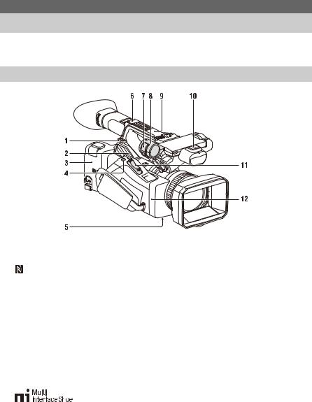
Main unit
1. Hook for shoulder strap (10)
2. ASSIGN7/DIRECT MENU button (40)
3. (N mark)
• Hold an NFC-compatible smartphone near this mark to establish a wireless connection between the camcorder and smartphone.
For details, refer to the operating instructions of the smartphone.
• NFC (Near Field Communication) is an international standard for short-range radio communication.
4. ASSIGN8/FOCUS MAG button
5. ZOOM switch (bottom) (28)
6. Multi Interface Shoe (rear)
For details about accessories supported by the Multi Interface Shoe, contact your sales representative.
7. Microphone clamper
8. Microphone holder (35)
9. GPS antenna
10. Multi Interface Shoe (front)
Overview
Location and Function of Parts
For details about the usage and function of each part, see the referenced page.
11.Power zoom lever (28)
12.Wi-Fi antenna
7
1.Internal microphone (34)
2.Recording/tally lamp (front) (122)
Flashes when the remaining capacity on the recording media or battery is low.
3.ASSIGN6 button
4.FULL AUTO button (27)
5.ND FILTER switch
6.ND FILTER mode switch
7.ASSIGN3/VIDEO SIGNAL MONITOR button
8.ASSIGN1/ZEBRA button
9.ASSIGN2/PEAKING button
10.INPUT1 switch (34)
11.CH1 (INT/EXT/MI SHOE) switch (34)
12.AUDIO LEVEL (CH1) dial (34)
13.AUDIO LEVEL (CH3) dial
14.AUDIO LEVEL (CH4) dial
15.AUDIO LEVEL (CH2) dial
16.CH2 (INT/EXT/MI SHOE) switch
17.INPUT2 switch (34)
18.ASSIGN5 button
19.SHUTTER switch
20.ASSIGN4/ONLINE button
21.ND control dial
22.WB SET button
23.Lens hood with lens cover (21)
8
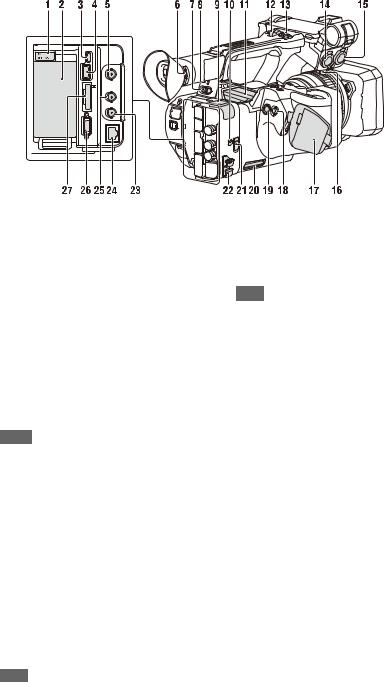
1.BATT RELEASE button (19)
2.Battery pack attachment (19)
3.Multi/Micro USB connector (81)
4.USB3.0 (HOST) connector (type A)
5.SDI OUT connector (79)
6.Diopter adjustment dial (22)
7.ON/STANDBY switch (20)
?: ON
1: STANDBY
8.Power lamp
9.USB2.0 (HOST) connector (type A) (59)
10.IN/OUT (input/output selector) switch
11.Air outlet
Notes
•Areas around the air outlet may become hot.
•Do not cover the air outlet.
12.Handle zoom lever (28)
13.Handle record button
When the lever is set to the HOLD position, the handle record button is not operable.
14.AUDIO INPUT1 connector (34)
15.AUDIO INPUT2 connector (34)
16.Cable holder
Provided for securing a microphone cable, etc.
17.Grip belt
18.Multi selector (V/v/B/b/SET button)
19.Record button (27)
20.Air inlet
Note
• Do not cover the air inlet.
21.REMOTE connector
The REMOTE connector is used for controlling start/stop of recording and other functions on the video device and peripherals connected to it.
22.Cable clamper
Note
•Do not use for any purpose other than securing cables.
23.GENLOCK IN/VIDEO OUT connector
24.Wired LAN connector
25.TC IN/OUT connector
26.HDMI OUT connector (79)
27.UTILITY SD/MS slot/access lamp
Used for proxy recording and storing/loading settings (File function). To be supported by a future upgrade (software update).
9
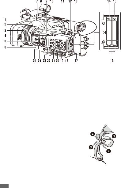
1.Zoom ring (29)
2.Focus ring (29)
3.Full MF switch (29)
Switch manual focus mode on/off by moving the focus ring forward/back.
4.Lens cover lever (21)
Opens/closes the lens cover.
5.MACRO switch (29)
6.FOCUS switch (29)
7.Hook for shoulder strap
8.STEADY SHOT button (36)
9.Iris ring (31)
10.IRIS switch (31)
11.i (headphone) jack
For stereo mini-jack headphones.
12.Recording/tally lamp (rear) (122)
Flashes when the remaining capacity on the recording media or battery is low.
13.SLOT SELECT button
14.SxS memory card A slot/access lamp (23)
15.SxS memory card B slot/access lamp (23)
16.EJECT button
When pressed, the EJECT button pops out. Press again to remove a card.
Note
•Pressing the EJECT button during recording will stop the recording.
17.DC IN connector
18.CANCEL/BACK button (86)
19.SEL/SET dial (86)
20.MENU button (86)
Button has a raised tactile bar for your convenience in locating the button.
21.WHT BAL switch (33)
22.GAIN switch (31)
23.ASSIGN10/IRIS PUSH AUTO button
24.ASSIGN9 button
25.FOCUS PUSH AUTO button (29)
To attach a shoulder strap
Attach a shoulder strap to the hooks for the shoulder strap.
10

1.THUMBNAIL button (72)
2.STOP button (73)
3.STATUS CHECK button (14)
4.PREV button (73)
5.V/v/B/b/SET button (86)
6.MENU button (86)
7.F REV button (73)
8.PLAY/PAUSE button (73)
9.F FWD button (73)
10.NEXT button (73)
11.LCD BRIGHT button (22)
12.DISPLAY button (12)
13.LCD screen (22)
14.Viewfinder (22)
15.Large eyecup
16.Air inlet
Note
• Do not cover the air inlet.
17.VOLUME buttons (30)
18.DURATION/TC/U-BIT button (36)
19.CANCEL button (86)
Bottom Side
1.Tripod screw holes (1/4 inch, 3/8 inch)
Compatible with 1/4-20UNC screws and 3/8- 16UNC screws.
Attach to a tripod (sold separately, screw length of 5.5 mm or less).
11
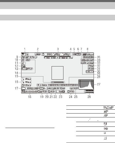
Screen Display
LCD/viewfinder screen
While recording, standing by to record, or during playback, the statuses and settings of the camcorder are superimposed on the LCD/viewfinder screen.
You can show/hide the information using the DISPLAY button.
You can also select to show/hide each item independently (page 105).
Information displayed on the screen while shooting
1. Network status indicator (page 13)
Displays the status of the network connection as an icon.
2. Uploading/Number of files to transfer indicator
3. Recording mode/slot A/B operation status indicator
|
zRec |
Recording |
|
Stby |
Recording standby |
4. Depth-of-field indicator
5. Network client mode status indicator
Displays the connection status in network client mode.
6. Streaming status indicator
7. Slow & Quick Motion shooting frame rate indicator
8. Remaining battery capacity/DC IN voltage indicator
9. Focus mode indicator (page 37)
FULL MF mode
MF mode
AF mode
Face detection AF (


 )
)
Face detection icon
Face only AF icon
Registered face icon
Face Only AF mode auto focus paused icon a)
a)Displayed when there is no registered face and no faces are detected, and when there is a registered face but it is not detected.
10.Zoom position indicator
Displays zoom position in the range of 0 (wide angle) to 99 (telephoto).
11.GPS status indicator
12.Image stabilization mode (SteadyShot) indicator
12
13.SDI output/HDMI output Rec Control indicator
Displayed when Display On/Off >SDI/HDMI Rec Control in the LCD/VF menu and SDI/ HDMI Rec Control >Setting in the Video menu are both set to On.
14.Digital extender indicator
15.Focus assist indicator
16.Media remaining capacity indicator
17.White balance mode indicator
|
ATW |
Automatic mode |
|
ATW Hold |
Pause automatic mode |
|
W:P |
Preset mode |
|
W:A |
Memory A mode |
|
W:B |
Memory B mode |
18.Timecode indicator (page 36)
19.ND filter indicator (page 32)
20.Scene file indicator (page 46)
21.Iris position indicator
22.Video level warning indicator
23.Gain indicator (page 31)
24.Shutter mode/shutter speed indicator
25.AE mode/AE level indicator
26.Audio level meter
27.VIDEO SIGNAL MONITOR display (waveform monitor/vectorscope/ histogram)
28.Clip name indicator
29.Recording format (codec) indicator
(page 118)
Displays the format that is recorded on an SxS memory card.
30.Gamma display assist indicator
31.Gamma indicator (page 96)
Displays the gamma setting.
32.Proxy status indicator
33.4K & HD (Sub) recording indicator
34.System frequency and scan method indicator
35.Recording format (picture size) indicator
(page 118)
Displays the picture size that is recorded on an SxS memory card.
Information displayed on the playback screen
The following information is superimposed on the playback picture.
1.Network status indicator
2.Uploading/Number of files to transfer indicator
3.Clip number/Total number of clips
4.Playback mode indicator
5.Playback format (frame rate) indicator
6.Playback format (picture size) indicator
7.Network client mode status indicator
8.Streaming status indicator
9.Remaining battery capacity/DC IN voltage indicator
10.Playback format (codec) indicator
11.Media indicator
A  mark appears to the left if the memory card is write-protected.
12.Time data indicator
The time data is displayed when Display On/Off >Timecode in the LCD/VF menu is set to On and the DISPLAY button is pressed.
13.Clip name indicator
14.Gamma display assist indicator
15.Audio level meter
16.Gamma indicator
Network connection icon indicators
|
Network |
Connection Icon |
|
mode |
status |
|
Access point |
Operating as an |
|
mode |
access point |
|
Access point |
|
|
operation error |
|
13

|
Network |
Connection |
Icon |
||
|
mode |
status |
|||
|
Station mode |
Wi-Fi |
|||
|
connected |
||||
|
Wi-Fi signal |
||||
|
strength (4 |
||||
|
levels) |
||||
|
Wi-Fi |
||||
|
disconnected |
||||
|
(incl. during |
||||
|
setup) |
||||
|
Wi-Fi |
||||
|
connection |
||||
|
error |
||||
|
Modem |
3G/4G signal |
3G connected |
||
|
strength (5 |
– |
|||
|
levels) |
||||
|
3 levels for |
||||
|
modems |
4G connected |
|||
|
without signal |
– |
|||
|
strength |
||||
|
detection |
Network |
|||
|
connection (3G/ |
||||
|
4G indeterminate) |
||||
|
– |
||||
|
3G/4G |
||||
|
disconnected |
||||
|
(incl. during |
||||
|
setup) |
||||
|
3G/4G |
||||
|
connection |
||||
|
error |
||||
|
Wired LAN |
LAN connected |
|||
|
LAN |
||||
|
connection |
||||
|
error |
||||
Status screen
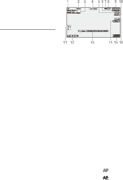
You can check the settings and status of the camcorder on the status screen.
Status screen operations
To display the status screen:
• Push the STATUS CHECK button.
To switch the status screen:
• Turn the SEL/SET dial or press the V/v button.
To hide the status screen:
• Push the STATUS CHECK button.
Camera Status screen
Displays the picture quality, zoom settings, and status.
|
White Switch<B> |
White balance memory B |
|
adjustment value |
|
|
White Switch<A> |
White balance memory A |
|
adjustment value |
|
|
White Switch<P> |
Preset White setting |
|
ND<Preset> |
Preset1 to 3 setting for ND |
|
Filter |
|
|
Zebra1 |
Zebra1 On/Off setting and |
|
level |
|
|
Zebra2 |
Zebra2 On/Off setting and |
|
level |
|
|
Gamma |
Gamma category and curve |
|
Gain Switch |
Gain<L>, Gain<M>, |
|
Gain<H> setting |
|
|
Handle Zoom Speed |
Handle Zoom setting |
|
Scene File |
Current scene file and file ID |
Audio Status screen
Displays the input setting, audio level meter, and wind noise reduction filter setting for each channel.
|
CH1 level meter |
CH1 level meter |
|
CH1 Input Source |
CH1 input source |
|
CH1 Ref./Sens. |
CH1 input reference level |
|
CH1 Wind Filter |
CH1 microphone wind |
|
reduction filter setting |
|
|
CH2 level meter |
CH2 level meter |
|
CH2 Input Source |
CH2 input source |
|
CH2 Ref./Sens. |
CH2 input reference level |
|
CH2 Wind Filter |
CH2 microphone wind |
|
reduction filter setting |
|
|
CH3 level meter |
CH3 level meter |
|
CH3 Input Source |
CH3 input source |
|
CH3 Ref./Sens. |
CH3 input reference level |
|
CH3 Wind Filter |
CH3 microphone wind |
|
reduction filter setting |
|
|
CH4 level meter |
CH4 level meter |
|
CH4 Input Source |
CH4 input source |
|
CH4 Ref./Sens. |
CH4 input reference level |
|
CH4 Wind Filter |
CH4 microphone wind |
|
reduction filter setting |
|
|
HDMI Output CH |
HDMI output audio channel |
|
combination setting |
|
|
Analog Output CH |
Analog output audio channel |
|
combination setting |
|
|
Monitor CH |
Monitor channel setting |
14

|
Headphone Out |
Headphone output type |
|
setting |
|
System Status screen
Displays the video signal settings.
|
Frequency/Scan |
System frequency and |
|
scanning method settings |
|
|
File System |
File system setting |
|
Codec |
Codec setting |
|
Simul Rec |
2-slot Simul Rec On/Off |
|
status |
|
|
Title Prefix |
Clip name title prefix |
|
Picture Size |
Recording format picture size |
|
Rec Function |
Enabled special recording |
|
format and settings |
|
|
Clip Continuous Rec |
Clip Continuous Rec On/Off |
|
status |
|
|
Picture Cache Rec |
Picture Cache Rec On/Off |
|
status and setting |
|
|
Number |
Clip name numeric suffix |
|
Shooting Mode |
Shooting mode setting |
|
4K & HD (Sub) Rec |
4K & HD (Sub) recording |
|
function On/Off status |
|
|
Proxy Rec |
Proxy recording On/Off |
|
status and setting |
|
|
Genlock |
Genlock status |
Video Output Status screen
Displays the SDI, HDMI, and video output settings.
|
SDI |
Output picture size |
|
Rec Control status |
|
|
Output On/Off |
|
|
HDMI |
Output picture size |
|
Rec Control status |
|
|
Output On/Off |
|
|
VIDEO |
Output picture size |
|
Output On/Off |
|
|
Gamma |
Gamma setting |
|
Color Gamut |
Color gamut setting |
|
Gamma Display Assist |
Gamma display assist setting |
Assignable Button Status screen
Displays the functions assigned to each of the assignable buttons.
|
1 |
Function assigned to the |
|
Assign 1 button |
|
|
2 |
Function assigned to the |
|
Assign 2 button |
|
|
3 |
Function assigned to the |
|
Assign 3 button |
|
|
4 |
Function assigned to the |
|
Assign 4 button |
|
|
5 |
Function assigned to the |
|
Assign 5 button |
|
|
6 |
Function assigned to the |
|
Assign 6 button |
|
|
7 |
Function assigned to the |
|
Assign 7 button |
|
|
8 |
Function assigned to the |
|
Assign 8 button |
|
|
9 |
Function assigned to the |
|
Assign 9 button |
|
|
10 |
Function assigned to the |
|
Assign 10 button |
|
Battery Status screen
Displays information about the battery and DC IN source.
|
Detected Battery |
Battery type |
|
Remaining |
Remaining capacity (%) |
|
Charge Count |
Number of recharges |
|
Capacity |
Remaining capacity (Ah) |
|
Voltage |
Voltage (V) |
|
Manufacture Date |
Date of battery manufacture |
|
Video Light Remaining |
Remaining charge level of the |
|
video light battery |
|
|
Power Source |
Power supply source |
|
Supplied Voltage |
Supplied power source |
|
voltage |
|
Media Status screen
Displays the remaining space, available recording time, and estimated service life of the recording media (SxS memory card A/SxS memory card B) and UTILITY media.
|
Media A information |
Displays the media icon |
|
when recording media is |
|
|
inserted in slot A. |
|
|
Media A protection |
Displays the lock icon when |
|
the recording media inserted |
|
|
in slot A is protected |
|
|
(locked). |
|
|
Media A remaining |
Displays the remaining |
|
capacity meter |
capacity of recording media |
|
inserted in slot A expressed |
|
|
as a percentage on a bar |
|
|
graph. |
|
15

|
Media A remaining |
Displays an estimate of the |
|
recording time |
remaining recording time of |
|
the recording media inserted |
|
|
in slot A in units of minutes |
|
|
under the current recording |
|
|
conditions. |
|
|
Remaining life of media |
Displays the remaining life in |
|
A |
percent (%) of the media |
|
inserted in slot A if the media |
|
|
stores remaining life data |
|
|
Media B information |
Displays the media icon |
|
when recording media is |
|
|
inserted in slot B. |
|
|
Media B protection |
Displays the lock icon when |
|
the recording media inserted |
|
|
in slot B is protected |
|
|
(locked). |
|
|
Media B remaining |
Displays the remaining |
|
capacity meter |
capacity of recording media |
|
inserted in slot B expressed |
|
|
as a percentage on a bar |
|
|
graph. |
|
|
Media B remaining |
Displays an estimate of the |
|
recording time |
remaining recording time of |
|
the recording media inserted |
|
|
in slot B in units of minutes |
|
|
under the current recording |
|
|
conditions. |
|
|
Remaining life of media |
Displays the remaining life in |
|
B |
percent (%) of the media |
|
inserted in slot B if the media |
|
|
stores remaining life data |
|
|
UTILITY media |
Displays the media icon |
|
information |
when media is inserted in the |
|
UTILITY SD/MS slot. |
|
|
UTILITY media |
Displays the lock icon when |
|
protection |
the media inserted in the |
|
UTILITY SD/MS slot is |
|
|
protected (locked). |
|
|
UTILITY media |
Displays the remaining |
|
remaining capacity |
capacity of media inserted in |
|
meter |
the UTILITY SD/MS slot |
|
expressed as a percentage on |
|
|
a bar graph. |
|
|
UTILITY media |
Displays an estimate of the |
|
remaining capacity |
remaining recording time of |
|
the recording media inserted |
|
|
in the UTILITY SD/MS slot |
|
|
in units of minutes. Or |
|
|
displays the remaining |
|
|
capacity in units of GB. |
|
Rec Button Settings Status screen
Displays the setting status of the record button and handle record button.
|
Rec Button |
Displays the recording target |
|
slot of the record button |
|
|
Handle Rec Button |
Displays the recording target |
|
slot of the handle record |
|
|
button |
|
GPS Status screen
Displays the GPS positioning status and information.
|
GPS |
GPS signal positioning status |
|
Dilution of Precision |
Position information |
|
precision |
|
|
Latitude |
Latitude information |
|
Longitude |
Longitude information |
|
Altitude |
Altitude information |
|
Positioning date and |
Positioning date and time |
|
time |
|
|
Current date and time |
Current date and time |
|
Time Zone |
Time zone setting |
Network Status screen
Displays the connection status of the network connection.
|
Wireless LAN |
Wireless network settings, |
|
connection status |
|
|
Wired LAN |
Wired LAN network settings, |
|
connection status |
|
|
Modem |
Wireless network settings, |
|
connection status using |
|
|
modem (sold separately) |
|
Wireless LAN settings
|
Setting |
Status |
Description |
|
display |
display |
|
|
Off |
— |
Wireless LAN |
|
setting is off. |
||
|
Access Point |
Non Active |
Not operating as an |
|
Mode |
access point. |
|
|
Displayed when |
||
|
Wi-Fi chip fails. |
||
|
Active |
Operating as an |
|
|
access point. |
||
16

|
Setting |
Status |
Description |
|
display |
display |
|
|
Station Mode |
Non Active |
Not operating in |
|
station mode. |
||
|
Displayed when |
||
|
Wi-Fi chip fails. |
||
|
Searching |
Attempting to |
|
|
connect to the |
||
|
previously |
||
|
connected network |
||
|
(access point). |
||
|
Disconnected |
Not connected to a |
|
|
network (access |
||
|
point). |
||
|
Also displayed |
||
|
when IP address |
||
|
was not assigned |
||
|
using DHCP. |
||
|
<SSID> |
Connected to |
|
|
<SSID> network |
||
|
(access point). |
||
Wired LAN settings
|
Setting |
Status |
Description |
|
display |
display |
|
|
Off |
— |
Wired LAN setting |
|
is off. |
||
|
On |
Disconnected |
Disconnected from |
|
network. |
||
|
Also displayed |
||
|
when IP address |
||
|
was not assigned |
||
|
using DHCP. |
||
|
Connected |
Connected to a |
|
|
network. |
||
|
Modem settings |
||
|
Setting |
Status |
Description |
|
display |
display |
|
|
Off |
— |
Modem setting is |
|
off. |
||
|
On |
Disconnected |
Not connected to a |
|
network. |
||
|
Connected |
Connected to a |
|
|
network. |
||
|
Connecting |
Attempting to |
|
|
connect to a |
||
|
network. |
||
|
No Modem |
Modem dongle is |
|
|
not inserted. |
||
NCM/Streaming Status screen
Displays the connection status and streaming status in network client mode.
|
Network Client Mode |
Network client mode status |
|
Status |
|
|
CCM Name |
Name of connected CCM in |
|
network client mode |
|
|
CCM Address |
Address of connected CCM |
|
in network client mode |
|
|
Streaming Status |
Streaming status |
|
Streaming Format |
Streaming format |
|
information |
|
|
Streaming Type |
Type of currently selected |
|
streaming setting |
|
|
Streaming Destination |
Streaming destination |
|
Address |
address |
|
Streaming Audio |
Audio channel to |
|
Channel |
superimpose on streaming |
|
output |
|
Network Client Mode Status settings
|
Status display |
Description |
|
|
Off |
Network client mode is off. |
|
|
Connected |
Network client mode is on, |
|
|
CCM/XDCAM air is |
||
|
connected, and control from |
||
|
CCM/XDCAM air is |
||
|
enabled. |
||
|
Connecting |
Attempting to connect to |
|
|
CCM/XDCAM air. |
||
|
Note |
||
|
If the status does not change |
||
|
from “Connecting,” the CCM |
||
|
address setting may be |
||
|
incorrect. Check that the |
||
|
address is set correctly. |
||
|
Destination Address |
The host name or IP address |
|
|
Error |
of the CCM to connect may |
|
|
be incorrect. |
||
|
Authentication Failed |
The user name or password |
|
|
used to connect to the CCM |
||
|
may be incorrect. |
||
|
No Network Access |
Cannot connect to a network. |
|
|
Check the network |
||
|
connection status and |
||
|
settings. |
||
|
Certificate is not yet |
The CCM certificate is not |
|
|
Valid |
valid. |
|
|
The network date and time |
||
|
settings may be incorrect. |
||
17

|
Status display |
Description |
|
|
Certificate has Expired |
The period of validity of the |
|
|
CCM certificate has expired. |
||
|
The network date and time |
||
|
settings may be incorrect. |
||
|
Root Certificate Error |
The root certificate is invalid. |
|
|
Note |
||
|
If this error message is |
||
|
displayed, contact your Sony |
||
|
service representative. |
Intermediate Cert. Error An intermediate certificate is invalid.
Note
If this error message is displayed, contact your Sony service representative.
Server Certificate Error The server certificate is
|
invalid. |
||
|
Note |
||
|
If this error message is |
||
|
displayed, contact your Sony |
||
|
service representative. |
||
|
Streaming Status settings |
||
|
Status display |
Description |
|
|
Off |
Streaming is off. |
|
|
Distributing |
Streaming is in progress. |
|
|
Preparing |
Preparing for streaming. |
|
|
Destination Address |
The host name or IP address |
|
|
Error |
of the streaming destination |
|
|
may be incorrect. |
||
|
No Network Access |
Cannot connect to a network. |
|
|
Check the network |
connection status and settings.
File Transfer Status screen
Displays file transfer information.
|
Auto Upload (Proxy) |
Auto Upload (Proxy) On/Off |
|
status |
|
|
Job Status(Remain/ |
Number of remaining jobs |
|
Total) |
and total number of jobs |
|
Total Transfer Progress |
Transfer progress of total jobs |
|
Auto Upload Server |
Name of Auto Upload |
|
(Proxy) transfer server |
|
|
Current File Transfer |
Transfer progress of file |
|
Progress |
currently being uploaded. |
|
Current Transferring |
Name of file currently being |
|
File Name |
uploaded. |
|
Server Address |
Address of file transfer server |
|
Destination Directory |
Destination directory of file |
|
transfer server |
|
18
Preparation
Power Supply
You can use a battery pack or AC power supply from an AC adapter.
When an AC adapter is connected, the AC adapter has priority even when a battery pack is attached.
For safety, use only the Sony battery packs and AC adaptors listed below.
Lithium-ion battery packs
BP-U30 (supplied)
BP-U60
BP-U60T
BP-U90
AC adapters/chargers
BC-U1A (supplied)
BC-U2A
WARNING
Do not store battery packs in locations exposed to direct sunlight, flame, or high temperature.
Note
•When operating from a power outlet, use the supplied AC adapter.
Using a battery pack
To attach a battery pack, plug the battery pack into the attachment (page 9) as far as it will go, and then slide it down to lock it into position.
To remove a battery pack, press and hold the BATT RELEASE button (page 9), slide the battery pack up and then pull it out of the attachment.
Notes
•Before use, charge the battery pack with the BC-U1A (supplied) or BC-U2A Charger.
•Charging a battery immediately after use while it is still warm may not fully recharge the battery.
•The BP-U30 cannot be used at the same time as a modem. To power a modem, use a BP-U60, BP-U60T, or BP-U90 battery pack.
•The high-capacity BP-U90 Battery Pack is large, and protrudes from the camcorder when attached. The BPU90 is convenient when using the camcorder attached to a tripod for extended recording periods.
Checking the remaining capacity
When recording or playback is in progress on the battery pack, an icon to show the current battery charge level and usage time remaining are displayed on the LCD/viewfinder screen
(page 12).
|
Icon |
Remaining capacity |
|
100% to 91% |
|
|
90% to 71% |
|
|
70% to 51% |
|
|
50% to 31% |
|
|
30% to 11% |
|
|
10% to 0% |
The camcorder indicates the remaining usage time in minutes by calculating the available time with the battery pack if operation is continued at the current rate of power consumption.
If the battery pack charge becomes low
If the remaining battery charge falls below a certain level during operation (Low Battery state), a low-battery message appears, the recording/tally lamp starts flashing, and a beep sound will warn you.
If the remaining battery charge falls below the level at which operation cannot continue (Battery Empty state), a battery-empty message appears. Replace with a charged battery pack.
Changing the warning levels
The Low Battery level is set to 10% of full battery charge and the Battery Empty level is set to 3% by factory default. You can change the warning level settings using Battery Alarm (page 122) in the System menu.
19
|
Using AC power |
Turning the camcorder on/off |
|
Connecting the camcorder to a power outlet |
To turn the camcorder on, set the ON/STANDBY |
|
allows use without worrying about the need to |
switch (page 9) to the ON position ([). To turn the |
|
recharge the battery pack. |
camcorder off, set the ON/STANDBY switch to |
|
the STANDBY position (1). |
|
|
Notes |
|
|
• Even when the ON/STANDBY switch is set to the |
|
|
STANDBY position, the unit continues to draw |
|
|
standby electric power. Remove the battery pack if not |
|
|
using your camcorder for an extended period. |
|
|
• Remove the battery or disconnect the DC IN power |
|
|
supply after the power lamp is extinguished when the |
|
|
power switch is set to the STANDBY position. If |
|
|
power is removed while the switch is in the ON |
|
|
position, a malfunction of the camcorder or SxS |
|
|
memory cards may occur. |
|
DC IN |
AC adapter plug |
|
connector |
1Connect the power cord (mains lead) to the AC Adapter.
2Connect the AC Adapter to the DC IN connector of the camcorder.
3Connect the power cord (mains lead) to the wall outlet (wall socket).
AC adapters
•Do not connect and use an AC adapter in a confined space, such as between a wall and furniture.
•If a problem occurs during operation, immediately disconnect the power cord from the outlet.
•Do not short-circuit the plug of the AC adapter with any metallic objects. Doing so will cause a malfunction.
•You cannot charge the camcorder by connecting it to the AC Adapter.
20
![]()
Setting the Clock
When you turn the camcorder on for the first time after purchasing or the backup battery has completely discharged, the initial setting display appears on the viewfinder screen and LCD screen.
Set the date and time of the internal clock using this screen.
Time Zone
The value shows the time difference from UTC (Coordinated Universal Time). Change the setting as required.
Setting the date and time
Move the cursor using the V/v/B/b button (page 9) or SEL/SET dial (page 10), and press the SET button or SEL/SET dial to set each item. Finally, move the cursor to [Finish] and press the SET button or SEL/SET dial to close the settings screen and finish setting the clock.
Once the settings screen is closed, you can change the date, time, and time zone settings using Clock Set (page 122) in the System menu.
Notes
•If the clock setting is lost because the backup battery becomes fully discharged due to power being disconnected for an extended period (no battery pack and no DC IN power source), the initial settings screen will be displayed when you next turn the camcorder on.
•While the initial settings screen is displayed, no other operation, except turning the power off, is permitted until you finish the settings on this screen.
•If you do not use your camcorder for about 3 months, the built-in rechargeable battery gets discharged and the date and time settings may be cleared from the memory. In that case, charge the rechargeable battery and then set the date and time again (page 126).
Attaching Devices
Attaching the lens hood
PUSH (lens hood release) button
Align the marks on the lens hood to those on the camcorder, and turn the lens hood in the direction of the arrow 2 until it is locked.
Removing the lens hood
Turn the lens hood in the opposite direction of the arrow in the illustration while pressing the PUSH (lens hood release) button.
Note
•Remove the lens hood when you attach/detach a ø77 mm polarizing filter or protective filter.
Attaching the large eyecup
Stretch the large eyecup slightly and fit it over the groove on the viewfinder.
Large eyecup (supplied)
21
Adjusting the Screens
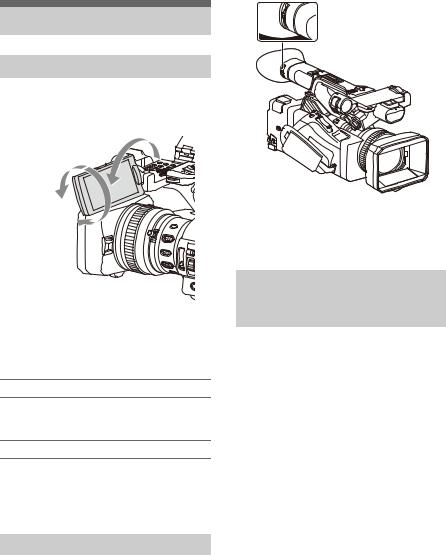
Adjusting the LCD screen
Open the LCD screen 180 degrees (1), then rotate it to the best angle to record or play back (2).
1 Open 180 degrees
2 90 degrees (max.)
2 180 degrees (max.)
You can adjust the angle so that the viewfinder is facing the subject. Images are displayed as mirror images on the LCD screen, but are recorded as normal images.
Adjusting the backlight
Switch the brightness of the backlight using the LCD BRIGHT button (page 11).
Adjusting the brightness
Adjust the brightness using LCD Setting >Brightness (page 103) in the LCD/VF menu. Changes in the brightness do not affect the brightness of recorded images.
Adjusting the viewfinder
Look through the viewfinder with the LCD screen closed when using the viewfinder.
If the viewfinder screen display is not clear, adjust it using the diopter adjustment dial below the viewfinder.
 Diopter adjustment dial
Move it until the picture becomes clear.
Adjusting the brightness
Adjust the brightness using VF Setting >Brightness (page 103) in the LCD/VF menu.
Adjusting the brightness of the LCD/viewfinder screen using an assignable button
You can display a level bar for adjusting the brightness of the LCD screen/viewfinder screen by assigning LCD/VF Adjust to an assignable button (page 40) beforehand and then pressing that button.
1 Press the button assigned with LCD/VF Adjust to display a level bar for adjusting the brightness.
Each time the button is pressed, the display switches in sequence between level bar for the LCD screen t level bar for the viewfinder t no display.
2 Adjust the level using the V/v/B/b button or SEL/SET dial, and press the SET button or SEL/SET dial.
The level bar disappears.
Press the button assigned with LCD/VF Adjust or do not perform any operation for 3 seconds to hide the level bar.
22

Using SxS Memory
Cards
This camcorder records audio and video on SxS memory cards (sold separately) inserted in the card slots.
About SxS memory cards
Supported memory cards
Use the following Sony SxS memory cards. Operations are not guaranteed with memory cards other than the following cards.
SxS PRO+ series
SxS PRO series
SxS-1 series
These cards comply with the ExpressCard standard.
For details on using SxS memory cards and usagerelated precautions, refer to the instruction manual for the SxS memory card.
For details about recording media and compatible formats, see page 130.
Notes
•When recording XAVC-I 3840×2160P, use SxS PRO+ memory cards.
•When recording in XAVC-I recording format or shooting Slow & Quick Motion with SxS PRO or SxS-1 memory cards, an unsupported media error may appear on the screen indicating that normal recording is not possible. The use of SxS PRO+ memory cards is recommended.
Inserting SxS memory cards
1 Open the cover of the card slot block.
2 Insert the SxS memory card with the SxS label facing to the right.
The access lamp (page 10) lights in red, then changes to green once the memory card is ready for use.
3 Close the cover.
Note
•The memory card, memory card slot, and image data on the memory card may be damaged if the card is forced into the slot in the incorrect orientation.
Removing an SxS memory card
1 Open the cover of the card slot block, and press the EJECT button.
The EJECT button pops out. During recording, this will stop the recording.
2 Press the EJECT button again to remove the card.
Notes
•If the camcorder is turned off or the memory card is removed while the memory card is being accessed, the integrity of data on the card cannot be guaranteed. All data recorded on the card may be discarded. Always make sure the access indicator is green or off before turning off the camcorder or removing the memory card.
•An SxS memory card removed from the camcorder after recording ended may be hot. This is not a malfunction.
Switching between SxS memory cards
When SxS memory cards are loaded in both card slots A and B, you can switch the card used for recording by pressing the SLOT SELECT button
(page 10).
If a card becomes full during recording, the camcorder automatically switches to the other card.
Note
•The SLOT SELECT button is disabled during playback. The memory cards are not switched even if you press the button. The button is enabled while the thumbnail screen (page 72) is displayed.
Formatting (initializing) an SxS memory card
If an SxS memory card is not formatted, or was formatted in another format, the message “Unsupported File System” is displayed on the LCD/viewfinder screen.
Format the card using the following procedure.
23

Using Format Media (page 110) in the Media menu, specify Media(A) (slot A) or Media(B) (slot B), then select Execute. When a confirmation message appears, select Execute again.
A message is displayed while formatting is in progress, and the access indicator is lit red. When formatting is completed, a completion message is displayed. Press the SEL/SET dial to dismiss the message.
If formatting fails
A write-protected SxS memory card or memory card that cannot be used with this camcorder will not be formatted.
If a warning message is displayed, replace the card with an appropriate SxS memory card, according to the instructions in the message.
Note
•Formatting a memory card erases all data, including recorded video data and setup files.
Checking the remaining recording time
While recording (or standing by to record), you can check the remaining space for the SxS memory cards loaded in the card slots on the A/B slot media status/remaining space display of the LCD/viewfinder screen (page 12).
The remaining recording time is calculated from the remaining capacity of the media in each slot and the current video format (recording bit rate), and is displayed in units of minutes.
Note
•A  icon appears if the memory card is writeprotected. If the write-protect switch is switched while the memory card is inserted, the lock icon will not be displayed. Always switch the write-protect switch with the memory card removed.
Replacing an SxS memory card
•If the available time on two cards in total becomes less than 5 minutes, the warning message “Media Near Full” is displayed, the recording/tally lamp flashes, and a beep sound is output to the headphones to warn you. Replace with media that has free space.
•If you continue recording until the total remaining time reaches zero, the message changes to “Media Full,” and recording stops.
Note
•Up to approximately 600 clips can be recorded on one SxS memory card.
If the number of recorded clips reaches the limit, an indication that the maximum number of clips has been reached is displayed.
Restoring an SxS memory card
If for any reason an error should occur in a memory card, the card must be restored before use.
When you load an SxS memory card that needs to be restored, a message appears on the LCD/ viewfinder screen to ask whether you want to restore it.
Restoring a card
Select Execute using the V/v/B/b button or
SEL/SET dial, and press the SET button or SEL/SET dial.
A message and progress status (%) are displayed while formatting is in progress, and the access lamp is lit red.
When restoration ends, a completion message appears.
If restoration fails
•Write protected SxS memory cards and cards on which memory errors have occurred cannot be restored. A warning message appears for such cards. Follow the instructions in the message and unprotect the card or replace it with another card.
•SxS memory cards on which memory errors have occurred may become usable if they are reformatted.
•In some cases, some clips can be restored while others cannot. The restored clips can be played normally.
•If the message “Could not Restore Some Clips” keeps appearing after repeated attempts at restoration, it may be possible to restore the SxS memory card with the following procedure.
1Use the copy function (page 76) of the camcorder to copy the required clips to another SxS memory card.
2Format the unusable SxS memory card on the camcorder.
3Copy the required clips back to the newly formatted SxS memory card.
24

Notes
•For restoration of media recorded with this camcorder, be sure to use this camcorder.
Media recorded with a device other than this camcorder or with another camcorder of different version (even of the same model) may not be restored using this camcorder.
•Clips shorter than 2 seconds cannot be restored.
Using Other Media
XQD memory cards
By using an optional QDA-EX1 Media Adapter, you can insert an XQD memory card into an SxS memory card slot and use it instead of an SxS memory card for recording and playback.
Compatible XQD cards
S-series XQD memory cards
G-series XQD memory cards
H-series XQD memory cards
N-series XQD memory cards
For details on using a QDA-EX1 Media Adapter, refer to the instruction manual supplied with it.
For details about recording media and compatible formats, see page 130.
Notes
•High-speed playback (page 73) may not be properly achieved with an XQD memory card.
•When recording in high rate formats, such as XAVC-I recording format or 3840×2160P, an unsupported media error may appear on the screen indicating that normal recording is not possible. The use of SxS PRO+ memory cards is recommended.
•Not all XQD memory cards are guaranteed to work with this camcorder. For compatible memory cards, contact your dealer.
Formatting (initializing)
XQD memory cards must be formatted the first time they are used in the camcorder.
An XQD memory card to be used with this camcorder must be formatted using the format function of this camcorder. It is also necessary to format an XQD memory card for use if a caution message is displayed when you mount the XQD memory card.
If an XQD memory card that was formatted in a format unsupported by this camcorder is inserted, the message “Unsupported File System” is displayed on the LCD/viewfinder screen. Format the media as described below.
25

To execute formatting
Using Format Media (page 110) in the Media menu, specify Media(A) (slot A) or Media(B) (slot B), then select Execute.
A message is displayed while formatting is in progress, and the access indicator is lit red. When formatting ends, a completion message appears.
Note
•Formatting an XQD memory card erases all data on the card, including protected video. The data cannot be restored.
To use media formatted on the camcorder in the slot of another device
Make a backup of the media, then format it using the other device.
SD cards
By using an optional MEAD-SD02, you can insert an SD card into an SxS memory card slot and use it instead of an SxS memory card for recording and playback.
For details about using an MEAD-SD02 Media Adapter, refer to the instruction manual supplied with the adapter.
For details about recording media and compatible formats, see page 130.
Note
•High-speed playback (page 73) may not be properly achieved with an SD card.
SDXC cards (exFAT only)
(Speed Class: Class 10)
Notes
•Not supported in modes other than exFAT mode.
•Do not use SDXC cards at the same time as other memory cards. If different types of media are used at the same time, the camcorder cannot switch cards when the media becomes full.
•When recording in XAVC-I recording format or shooting Slow & Quick Motion (page 43), an unsupported media error may appear on the screen indicating that normal recording is not possible, depending on the SDXC cards used. The use of SxS PRO+ memory cards is recommended.
•SDXC cards recorded using PMW series and PXW series camcorders may not be supported, depending on the camcorder model.
For details, contact your Sony dealer or a Sony service representative.
SDHC cards (FAT only)
(Speed Class: Class 10)
Note
• Not supported in exFAT and UDF modes.
Formatting (initializing)
SD cards must be formatted the first time they are used in the camcorder.
SD cards for use in the camcorder should be formatted using the format function of the camcorder.
If a message appears when the SD card is inserted into the camcorder, format the SD card.
If an SD memory card that was formatted in a format unsupported by this camcorder is inserted, the message “Unsupported File System” is displayed on the LCD/viewfinder screen. Format the media as described below.
To execute formatting
Using Format Media (page 110) in the Media menu, specify Media(A) (slot A) or Media(B) (slot B), then select Execute.
A message is displayed while formatting is in progress, and the access indicator is lit red. When formatting ends, a completion message appears.
Note
•Formatting an SD card erases all data on the card, including protected video. The data cannot be restored.
To use media formatted on the camcorder in the slot of another device
Make a backup of the media, then format it using the other device.
26

Shooting
Basic Operation Procedure
Shooting
Basic shooting is conducted using the following procedure.
1 Attach the necessary devices, and check that power is being supplied.
2 Load the memory card(s).
If you load two SxS memory cards in memory card slots A and B, recording is continued by automatically switching to the second card when the first card becomes full.
3 Set the ON/STANDBY switch to the ON position.
The recording screen is displayed on the LCD/viewfinder screen.
4 Press the grip or handle record button
(page 9).
The recording/tally lamp lights and recording begins.
5 To stop recording, press the record button again.
Recording stops, and the camcorder switches to STBY (standby) mode.
Shooting (Full Auto Mode)
Press the FULL AUTO button, turning the button indicator on.
Full Auto mode is turned on, Auto Exposure (page 92) is activated, and Auto ND Filter, Auto Iris, AGC (Auto Gain Control), Auto Shutter, and ATW (Auto Tracing White balance) are set to On. Then, the brightness and white balance are automatically adjusted.
When you wish to adjust them manually, turn Full Auto mode off.
Continuous recording on the memory cards (Relay Rec)
When memory cards are inserted in both slots A and B, recording automatically switches to the second memory card just before the remaining capacity on the first card is reduced to zero. You can continue recording continuously when switching memory cards by replacing the memory card that is full with a new memory card.
Notes
•Do not eject a memory card while recording to it is in progress. Remove only the memory card in the slot whose access lamp is turned off during recording.
•If a recordable memory card is loaded into the other slot when the remaining time of the memory card that is recording is less than 1 minute, the message “Will Switch Slots Soon” is displayed. The message disappears after switching memory card slots.
•The relay recording function may not work if you start recording when the remaining time of the memory card is less than 1 minute. To perform the relay recording properly, make sure that the remaining time of the memory card is more than 1 minute.
•Video created using the camcorder relay recording function cannot be played back seamlessly on the camcorder.
•To combine video created using the camcorder relay recording function, use Content Browser software.
27
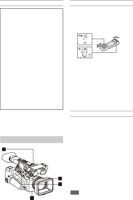
About clips
Clip (recording data)
When you stop recording, video, audio, and subsidiary data from the start to end of the recording are recorded as a single clip on an SxS memory card.
Clip names
Each clip recorded by the camcorder is automatically assigned a name using the naming mode that is set in Clip Naming (page 111) of the Media menu.
Maximum clip duration
The maximum duration of a clip varies depending on the recording format. The maximum duration of continuous
recording is the same as the maximum duration of a clip. If the recording time exceeds the maximum duration of a clip, a new clip is created automatically and recording continues. The new clip appears as a separate clip on the thumbnail screen.
For details about the maximum recording time of a clip for each recording format, see
“Maximum recording time for a clip” (page 131).
To delete a clip
You can delete the last recorded clip using the Last Clip Delete function (page 121). To delete all clips or specific clips, perform the operation from the thumbnail screen (page 77).
Adjusting the zoom
Using the power zoom lever
1.Set the ZOOM switch Dto SERVO.
2.Zoom by pressing the power zoom lever C. Lightly press the power zoom lever Cfor a
slower zoom. Fully press it for a faster zoom.
Wide view: Wide
Close view: Telephoto
•The minimum distance required between your camcorder and the subject for focus is about 5 cm (about 2 in.) for wide angle and about 80 cm (about 2 5/8 feet) for telephoto.
•The focus may not be adjusted at certain zoom positions if the subject is within 80 cm (about 2 5/8 feet) from your camcorder.
•Keep your finger on the power zoom lever C.
If you move your finger off the power zoom lever C, the operation sound of the power
zoom lever may also be recorded.
Using the handle zoom
1.Set the handle zoom operation to “Low,” “High,” or “Variable” using Handle Zoom (page 93) >Setting in the Camera menu.
•When set to “Variable,” you can zoom in or out at a variable speed according to the pressure applied to the switch.
•When set to “Low” or “High”, you can zoom in or out at fixed speed, regardless of the pressure applied to the switch. You can set the speed to “Low” or “High” using Handle Zoom in the Camera menu.
•By assigning the Handle Zoom >Setting function to an assignable button (page 40), you can switch the handle zoom operation each time the button is pressed.
2.Press the handle zoom lever Ato zoom in or out.
Note
•You cannot use the handle zoom lever Awhen the handle zoom operation is set to OFF.
28
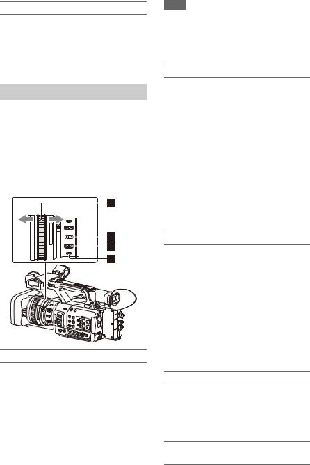
Using the zoom ring
1.Set the ZOOM switch Dto MANUAL.
2.Zoom by turning the zoom ring B.
You can zoom at the desired speed by turning the zoom ring B. Fine adjustment is also possible.
Adjusting the focus
Tips for focusing
•Move the power zoom lever towards T (telephoto) and adjust the focus, then, towards W (wide angle) to adjust the zoom for recording.
•When you want to record a close-up image of a subject, move the power zoom lever towards W (wide angle) to fully magnify the image, then adjust the focus.
Adjusting in Full MF mode
Pull the focus ring Atoward the back (toward the camcorder) to activate Full MF mode for full manual focus control.
Turn the focus ring to adjust the focus while monitoring the image on the LCD/viewfinder screen.
In Full MF mode, you can use the distance markers printed on the focus ring as a guide when adjusting the focus. The distances where the picture is in focus correspond to the positions of the distance markers.
Notes
•Do not use excessive force at both ends of the travel when turning the focus ring.
•While in Full MF mode, the auto focus and push auto focus functions do not work.
•The macro is set to OFF regardless of the setting of the lens MACRO switch.
Adjusting in MF mode
In MF (manual focus) mode, you can also use auto focus operation whenever required.
Slide the focus ring Atoward the front (toward the lens hood) and set the FOCUS switch Cto MANUAL.
Using automatic focus temporarily (Push auto focus)
In MF mode, auto focus is activated while the FOCUS PUSH AUTO button Dof the lens is pressed or while an assignable button (page 40) assigned with Push AF/Push MF is pressed.
The focus returns to manual focus when you release the button.
This function is useful for shifting the focus from one subject to another during manual focus mode.
Adjusting in AF mode
In AF (auto focus) mode, the focus is adjusted automatically.
Slide the focus ring Atoward the front and set the FOCUS switch Cto AUTO.
Using manual focus temporarily (Push manual focus)
In AF mode, manual focus is activated while the FOCUS PUSH AUTO button of the lens is pressed or while an assignable button (page 40) assigned with Push AF/Push MF is pressed. The focus returns to auto focus when you release the button.
Using macro mode
In MF mode or AF mode, set the MACRO switch Bto the ON position to activate macro mode to enable focusing over a range that includes the macro area.
Macro mode is disabled in Full MF mode.
Focusing using magnified view (Focus Magnifier)
When an assignable button (page 40) assigned with Focus Magnifier is pressed, the focus
29

magnifier screen appears showing the part of the image magnified.
The magnification switches between 4× and 8× each time the button is pressed when the recording format is QFHD. You can move the magnified position using the V/v/B/b button. The center of the screen is magnified at a fixed 2× in recording formats other than QFHD.
Press the button again to return to the normal screen.
This function is useful for checking the focus.
Note
•Even though the image appears magnified on the screen, the recorded image is not magnified.
Monitoring audio while shooting
Connecting a set of headphones to the headphone jack (stereo mini jack) (page 10) enables you to monitor the audio being recorded.
Note
•The built-in speaker is disabled while shooting (recording or recording standby).
To adjust the audio monitoring volume
Use the VOLUME buttons (page 11).
To change the audio monitoring channel
Select the channel using Audio Output (page 102) in the Audio menu.
Changing Basic Settings
You can change the settings based on the video application or recording conditions.
Video format
The formats available for selection vary depending on the exFAT/UDF/FAT file system, system frequency, and codec settings.
Switching the exFAT/UDF/FAT file system
Switch using Rec Format (page 118) >File System in the System menu.
The camcorder automatically restarts after switching.
Note
•You cannot switch between exFAT/UDF/FAT during recording or playback.
Switching the system frequency
Switch using Rec Format (page 118) >Frequency in the System menu.
The camcorder automatically restarts after switching.
Note
•You cannot switch the system frequency during recording or playback.
Switching the codec
Switch using Rec Format (page 118) >Codec in the System menu.
Note
•You cannot switch the codec during recording or playback.
Changing the format
Switch using Rec Format (page 118) >Video Format in the System menu.
The signals from the SDI OUT and HDMI OUT connectors are also output in the format selected using this menu.
30
![]()
Note
•You cannot change the format during recording or playback.
Adjusting the brightness
You can adjust the brightness by adjusting the iris, gain, shutter speed, and by adjusting the light level using ND filters.
Shooting using auto iris
When Full Auto mode (page 27) is on
The iris is forcibly set to Auto mode.
When Full Auto mode is off
Set the IRIS switch B to AUTO. Auto mode is set.
When the IRIS switch is set to AUTO, the adjustment setting applied when the iris AUTO/ MANUAL switch is set to MANUAL can be configured in the direct menu (page 37).
Shooting using manual iris
When Full Auto mode is off, set the IRIS switch B to MANUAL. Manual mode is set. Turn the iris ring Ato adjust the iris.
Switching to auto iris temporarily
In manual iris mode, press an assignable button assigned with Push Auto Iris to activate the onepush auto iris function.
Auto iris is active while the button is pressed. Release the button to return to manual iris mode.
Shooting with auto gain (AGC)
When Full Auto mode (page 27) is on
AGC (Auto Gain Control) mode is forcibly enabled.
When Full Auto mode is off
Set Auto Exposure >AGC (page 92) in the Camera menu to On to activate AGC mode. You can also set AGC on/off in the direct menu
(page 37).
Shooting with fixed gain
1.Set Full Auto mode off.
2.When the gain is automatically adjusted, set Auto Exposure >AGC (page 92) in the Camera menu to Off.
“AGC” disappears.
3.Set the GAIN switch Gto H, M, or L. The gain value set for the selected gain switch position appears on the screen.
You can set the gain value for H/M/L using Gain (page 91) in the Camera menu.
You can also set the H/M/L value in the direct menu (page 37).
Shooting in auto shutter mode
When Full Auto mode (page 27) is on
The shutter is forcibly set to auto shutter.
When Full Auto mode is off
Set Auto Exposure >Auto Shutter (page 93) in the Camera menu to On to activate auto shutter speed mode.
Auto shutter can also be activated by selecting Auto Shutter in the direct menu and setting it to on.
Shooting with a fixed shutter
When Full Auto mode is off and Auto Exposure >Auto Shutter (page 93) in the Camera menu is set to Off, set the SHUTTER switch Fto the ON position to set fixed shutter with the shutter mode and speed configured using Shutter (page 92) in the Camera menu.
31

Setting in the Camera menu
Select Shutter (page 92) in the Camera menu and set the shutter mode and speed.
Setting using the direct menu
You can also set ECS mode (page 92) on/off and the shutter speed in the direct menu (page 37).
Adjusting the light level (ND filter)
You can shoot a subject with the proper brightness by using the ND FILTER switch C when the recording environment is too bright. The camcorder features two ND filter modes. You can switch the mode using the ND FILTER mode switch D.
Preset mode
Set the ND FILTER mode switch Dto PRESET, then set the ND FILTER switch Cto the following.
CLEAR: ND filter is not used.
1:Filter density set using ND Filter >Preset1 in the Camera menu. The default setting is 1/4.
2:Filter density set using ND Filter >Preset2 in the Camera menu. The default setting is 1/16.
3:Filter density set using ND Filter >Preset3 in the Camera menu. The default setting is 1/64. You can also set the filter in the same way as the ND FILTER switch using the direct menu
(page 37).
Variable mode
Set the ND FILTER mode switch Dto PRESET, then set the ND FILTER switch Cto the following.
CLEAR: ND filter is not used.
1, 2, 3: You can set the filter density in a continuous range from 1/4 to 1/128 using the ND control dial E.
The ND FILTER switch Bposition (1/2/3) does not affect the filter density adjustment.
Auto ND filter
When the ND FILTER mode switch is set to VARIABLE and the ND FILTER switch is in position 1 to 3, the density of the ND filter can be adjusted automatically by setting Auto Exposure >Auto ND Filter (page 92) in the Camera menu to On.
You can also set Auto ND Filter on/off and set ND CLEAR in the direct menu (page 37). When Auto ND Filter is off, you can also select the density of the ND filter in the direct menu.
Setting auto exposure
Auto exposure controls excessive brightness to an appropriate level using auto ND filter, iris, gain, and shutter functions.
Set the control mode using Auto Exposure (page 92) >Mode in the Camera menu, and set the level using Level.
You can also set the control mode and correction level in the direct menu (page 37).
Using the flicker reduction function
Set Flicker Reduce (page 93) >Mode in the Camera menu to Auto or On, and set Frequency to the power supply frequency (50 Hz or 60 Hz).
Note
•If the frame rate for shooting is close to the power supply frequency, flicker may not be completely reduced when using the flicker reduction function. In this case, use the electronic shutter.
Adjusting for natural colors (white balance)
You can select the adjustment mode to suit the shooting conditions.
Preset mode
This mode adjusts the color temperature to a preset value (factory default is 3200K). Select this mode when you have no time to adjust the white balance or when you wish to fix the white balance to the preset set using White (page 95) >Preset White in the Paint menu.
32

Memory A mode, Memory B mode
This mode adjusts the white balance to the setting saved in memory A or B, respectively.
Press the WB SET button Ato execute auto white balance adjustment and store the adjusted value in memory A or memory B.
ATW (Auto-Tracing White balance) mode
In this mode, the camcorder automatically adjusts the white balance to the appropriate condition. The white balance is automatically adjusted when the color temperature of the light source changes. You can select the speed of adjustment (five steps) using White Setting >ATW Speed
(page 95) in the Paint menu.
You can freeze the current white balance setting by assigning the ATW Hold function to an assignable button (page 40), and pressing the assignable button to temporarily pause ATW mode.
Note
•It may not be possible to adjust to the appropriate colors using ATW, depending on the lighting and subject conditions.
Examples:
When a single color dominates the subject, such as sky, sea, ground, or flowers.
When the color temperature is extremely high or extremely low.
If the appropriate effect cannot be obtained because the ATW auto tracking speed is slow or for other reasons, run auto white balance.
Using the switch
Select the mode using the WHT BAL switch B. B: ATW mode or Memory B mode
A: Memory A mode PRESET: Preset mode
ATW mode is assigned to the B position of the WHT BAL switch at the factory. You can change the setting so that Memory B mode is selected using White Setting >White Switch<B>
(page 95) in the Paint menu.
Setting the camcorder to Full Auto mode (page 27) forcibly activates ATW mode. Assigning the ATW on/off function to an assignable button (page 40) permits you to independently activate/deactivate ATW when Full Auto mode is off.
Using the direct menu
Press the DISPLAY button (page 11) to display the selected mode and color temperature on the screen (page 12).
ATW: ATW mode W:A: Memory A mode W:B: Memory B mode W:P: Preset mode
You can change the adjustment mode to the following in the direct menu (page 37). When the WHT BAL switch is set to the B
position, ATW mode and Memory B mode can be set.
When the WHT BAL switch is set to the A position, ATW mode and Memory A mode can be set.
When the WHT BAL switch is set to the PRESET position, ATW mode and Preset mode can be set. You can set the color temperature in the direct menu when not set to ATW mode.
You can change the color temperature in the direct menu by selecting the color temperature indicator. In preset mode, pressing the WB SET button also sets the color temperature.
Switching preset mode using an assignable button
Assign Preset White Select to an assignable button (page 40). You can then switch preset mode values in the order 3200K, 4300K, 5600K, and 6300K each time you press the button.
Executing auto white balance
1 To save an adjustment value in memory, select Memory A mode or Memory B mode.
2 Place white paper (or other object) in a location with the same lighting source and conditions as the subject, then zoom in on the paper to show white on the screen.
3 Adjust the brightness.
Adjust the iris as described in “Shooting using manual iris” (page 31).
33

4 Press the WB SET button A.
When you execute the adjustment in a memory mode, the adjusted value is stored in the memory (A or B) selected in step 1.
If auto white balance is executed in ATW mode, the white balance adjustment returns to the ATW mode white balance when adjustment ends.
Notes
•Auto white balance adjustment cannot be performed when in Preset mode.
•If the adjustment is not successful, an error message is displayed on the screen. If the error message persists after repeated attempts to set white balance, contact your Sony service representative.
Setting the audio to record
The following connectors, switches and dials allow you to set the sound to be recorded.
External audio input connectors and selector switches
AUDIO INPUT1 connector A AUDIO INPUT2 connector B INPUT1 switch C
INPUT2 switch J
Audio source switches
CH1 (INT/EXT/MI SHOE) switch D CH2 (INT/EXT/MI SHOE) switch I
Switches for setting the audio level
AUDIO LEVEL (CH1) dial E
AUDIO LEVEL (CH2) dial H
AUDIO LEVEL (CH3) dial F
AUDIO LEVEL (CH4) dial G
Refer to the block diagrams (page 143).
Using the internal microphone
You can record sound using the internal microphone.
To record on CH1, CH2
Set the CH1 (INT/EXT/MI SHOE) switch Dand CH2 (INT/EXT/MI SHOE) switch Ito INT.
To record on CH3, CH4
Select Internal MIC using Audio Input (page 101) >CH3 Input Select and CH4 Input Select in the Audio menu.
Using an external audio device
Mixers and other external audio devices are supported.
To record on CH1, CH2
1 Set the CH1 (INT/EXT/MI SHOE) switch Dand CH2 (INT/EXT/MI SHOE) switch Ito EXT.
When Audio Input >CH2 EXT Input Select in the Audio menu is set to INPUT2, the sound from the AUDIO INPUT1 connector will be recorded on CH1 and the sound from the AUDIO INPUT2 connector will be recorded on CH2.
When CH2 EXT Input Select is set to INPUT1, the sound from the AUDIO INPUT1 connector will be recorded on both CH1 and CH2.
2 Set the INPUT1/INPUT2 switches (C/ J) to LINE.
3 Connect an external audio device to the AUDIO INPUT1/AUDIO INPUT2 connectors (A/B).
34

To record on CH3, CH4
1 Select INPUT1 using Audio Input (page 101) >CH3 Input Select and INPUT2 using CH4 Input Select in the Audio menu.
If INPUT1 is selected using CH4 Input Select, the sound from the AUDIO INPUT1 connector will be recorded on both CH3 and CH4.
2 Perform steps 2 and 3 as described in “To record on CH1, CH2.”
Using an external microphone
An electret condenser microphone or other devices can be connected and used for recording.
To record on CH1, CH2
1 Set the CH1 (INT/EXT/MI SHOE) switch Dand CH2 (INT/EXT/MI SHOE) switch Ito EXT.
When Audio Input >CH2 EXT Input Select in the Audio menu is set to INPUT2, the sound from the AUDIO INPUT1 connector will be recorded on CH1 and the sound from the AUDIO INPUT2 connector will be recorded on CH2.
When CH2 EXT Input Select is set to INPUT1, the sound from the AUDIO INPUT1 connector will be recorded on both CH1 and CH2.
2 Set the INPUT1/INPUT2 switches (C/ J).
MIC: For microphone that does not require phantom power.
MIC+48V: For microphone that requires +48 V phantom power.
Notes
•Selecting MIC+48V and connecting a microphone that is not compatible with a +48 V source may damage the connected device. Check before connecting the device.
•If noise is a concern on connectors with no device connected, set the corresponding INPUT1/ INPUT2 switches to LINE.
3 Open the cover by pulling up the handle of the microphone holder.
4 Attach a microphone, then close the microphone holder to secure the microphone.
5 Connect the microphone cable to the AUDIO INPUT1/AUDIO INPUT2 connectors (A/B).
When you use a stereo microphone (two XLR plugs), connect the L (left) channel plug to the AUDIO INPUT1 connector, and the R (right) channel plug to the AUDIO INPUT2 connector.
To record on CH3, CH4
1 Select INPUT1 using Audio Input (page 101) >CH3 Input Select and INPUT2 using CH4 Input Select in the Audio menu.
If INPUT1 is selected using CH4 Input Select, the sound from the AUDIO INPUT1 connector will be recorded on both CH3 and CH4.
2 Perform steps 2 to 5 as described in “To record on CH1, CH2.”
Using a multi-interface shoe compatible microphone
To record on CH1, CH2
1 Set the CH1 (INT/EXT/MI SHOE) switch Dand CH2 (INT/EXT/MI SHOE) switch Ito MI SHOE.
2 Attach a microphone to the multiinterface shoe.
To record on CH3, CH4
1 Select Shoe CH1 using Audio Input (page 101) >CH3 Input Select and Shoe CH2 using CH4 Input Select in the Audio menu.
2 Attach a microphone to the multiinterface shoe.
Note
•Two microphones cannot be connected to the front and rear Multi Interface Shoe at the same time. The first connected microphone is the active microphone.
35

Adjusting the audio recording level
Adjusting automatically (AGC)
Set the AUDIO LEVEL (CH1/CH2/CH3/ CH4) dials (E/H/F/G) to AUTO.
You can set whether the levels on CH1 and CH2 are automatically adjusted separately (Mono) or together (Stereo) using Audio Input (page 101)
>CH1&2 AGC Mode in the Audio menu. Similarly, you can set whether the levels on CH3 and CH4 are automatically adjusted separately (Mono) or together (Stereo) using CH3&4 AGC Mode.
Adjusting manually
During shooting or standby, turn the AUDIO LEVEL (CH1/CH2/CH3/CH4) dials (E/H/F/G) of the corresponding channels in the range 0 to 10 to adjust the recording level.
To reduce wind noise, set Audio Input >CH Wind Filter in the Audio menu to On (page 101).
Audio recording in special recording modes
Audio is not recorded in Interval Rec mode or Slow & Quick Motion mode.
Image stabilization
Enabling the image stabilization (SteadyShot) function suppresses image shaking caused by camera movement when recording.
Press the STEADY SHOT button on the lens.
The SteadyShot mode turns on/off each time you press the button.
The setting is displayed on the LCD/viewfinder screen.
Note
•When shooting using a tripod for stability, set SteadyShot to Off.
Time data
Setting the timecode
Set the timecode to record using Timecode (page 107) in the TC/UB menu.
Setting user bits
You can add an 8-digit hexadecimal number to the recorded image as user bits. You can also set the user bits to the current time.
Set using Users Bit (page 107) in the TC/UB menu.
Displaying time data
Press the DISPLAY button to display time data on the screen (page 12).
The indication is switched among the timecode, user bits, and recording duration each time you press the DURATION/TC/U-BIT button
(page 11).
|
Display |
Description |
|
TCG **:**:**:** |
Timecode |
|
CLK **:**:**:** |
Timecode (Clock mode) |
|
UBG ** ** ** ** |
User bits |
|
DUR **:**:**:** |
Duration from the beginning |
|
of recording |
|
36

Useful Functions
Direct menu operation
You can check status and change settings for some items displayed directly on the LCD/ viewfinder screen.
The Direct Menu function is used by assigning the function to an assignable button.
The following items can be configured.
•Auto focus mode
•ATW
•Preset White
•Color Temp <A>/Color Temp <B>
•Scene File
•ND Filter Position
•Auto ND Filter
•ND Filter value
•Auto Iris
•Iris value
•AGC
•Gain value (H/M/L/Turbo)
•ECS
•Auto Shutter
•Shutter Speed value
•Shutter Angle value
•Auto Exposure Mode
•Auto Exposure Level
•S&Q Frame Rate
Note
•Direct menu operation is not available when Full Auto mode (page 27) is on (FULL AUTO button indicator is lit).
1 Press the assignable button assigned with Direct Menu.
When information is displayed on the LCD/ viewfinder screen using the DISPLAY button, only the items on the screen that can be configured using the direct menu are selectable using the cursor.
When information is not displayed on the LCD/viewfinder screen, only items that can be configured using the direct menu are displayed and are selectable using the cursor.
2 Move the cursor to the desired item using the V/v/B/b button or SEL/SET dial, and press the SET button or SEL/ SET dial.
The direct menu for the selected item appears.
3 Select a setting using the V/v button or
SEL/SET dial, and press the SET button or SEL/SET dial.
The cursor disappears and the new setting is displayed.
Press the assignable button assigned with Direct Menu again or wait 3 seconds without performing any action to close the direct menu and return to the shooting screen.
You can open the direct menu by setting Menu Settings >Direct Menu with <SET> (page 123) in the System menu to On and pressing the SET button or SEL/SET dial. However, the face detection AF registered face function becomes unavailable.
Face detection AF
The camcorder can detect people’s faces and then adjust the focus on faces.
This function is available only when focus adjustment is in AF mode or during push auto focus.
When faces are detected, gray face detection frames are displayed. The frames change to white after auto focus is established. When multiple individuals are detected, the main subject is automatically determined.
Set the face detection AF action using Focus (page 91) in the Camera menu.
Face Only AF: The camera detects the faces of subjects (people) and focuses only on their faces. While a face is not detected, AF is temporarily stopped (MF), and the Face Only AF mode auto focus paused icon 
(page 12) is displayed. This mode is effective when face detection has not stabilized.
Face Priority AF: The camera detects the faces of subjects (people) and prioritizes the focusing on the faces. When a face is not detected, focusing is in AF mode (default setting).
Off: The face detection AF function is disabled.
37

Notes
•During push auto focus operation, Face Priority AF is activated even if Face Only AF is currently selected.
•Face detection AF is not available in the following cases.
In FULL MF mode
When the FOCUS switch is set to MANUAL (excluding during push auto focus operation)
When the recording format is DVCAM
•If you turn the camcorder off while Face Only AF is selected, the mode automatically switches to Face Priority AF when the camcorder is next turned on.
Hiding face detection frames
You can show/hide face detection frames using Display On/Off >Face Detection Frame
(page 105) in the LCD/VF menu.
Focusing on a registered face
During face detection AF operation, you can register a face for a subject (person) for focusing on that face.
Only one face can be registered. Registering a face overwrites the existing registration. When a face is registered, the detection frame
changes to a double frame, and the registered face icon  (page 12) is displayed.
In face detection AF, the following actions occur depending on the combination of registered face and face detection AF operating mode.
Face Priority AF (with registered face): If the camera detects the registered face, the camera focuses on that face. If the registered face is not detected, normal Face Priority AF is activated.
Face Only AF (with registered face): If the camera detects the registered face, the camera focuses on that face. While the registered face is not detected, AF is temporarily stopped (MF), and the Face Only AF mode auto focus paused icon 
(page 12) is displayed. This mode is effective when you want to auto focus on the registered person.
Setting the registered face
Move the face selection cursor (orange underline) to the face to register using the V/ v/B/b button, and press the SET button or
SEL/SET dial.
|
Registered face frame |
||||||||
|
Other faces (gray) |
(double white frame) |
|||||||
Face selection cursor (orange)
Clearing the registered face
Move the selection cursor to the registered face using the V/v/B/b button, and press the SET button or SEL/SET dial.
The registered face is cleared, the face frame becomes a single frame, and the registered face icon disappears.
When faces are detected with the registered face frame not displayed and the face selection cursor (orange) displayed, you can clear the registered face by pressing the SET button or SEL/SET dial twice.
Notes
•Faces may not be detected depending on the recording environment, condition of the subject, or the settings.
•You may not be able to get the proper effect, or objects other than people’s faces may be detected as a face, in some recording environments. In this case, set the face detection AF function to Off.
•Registration of the face of the intended individual for focusing before shooting is recommended.
•Face registration may not be successful depending on hairstyle, facial decoration, or if not directly facing the camera. In this case, the face frame may become a double frame, but the registered face icon is not displayed and the face is not registered.
•If a face has already been registered, clearing the existing face and then registering the new face is recommended.
•The registered face function is not available when Menu Settings >Direct Menu with <SET> (page 123) in the System menu is set to On.
Switching face detection AF operation using an assignable button
Assign Face Detection AF to an assignable button (page 40). You can then switch face detection AF operation in the order Face Priority AF, Face Only AF, and Off each time you press the button.
Setting using the direct menu
You can also set the face detection AF operation using the direct menu (page 37).
38

Color bars/reference audio tone
You can output color bars instead of the camera image by setting Color Bars (page 93) >Setting in the Camera menu to On. The image output is restored when set to Off.
A 1 kHz reference audio tone can also be output with the color bars by setting Audio Input (page 101) >1kHz Tone on Color Bars in the Audio menu to On.
The color-bar signal and reference-tone signal are output from the SDI OUT, HDMI OUT, and VIDEO OUT (color bars only) connectors.
You can set the type of color bars using Color Bars >Type in the Camera menu.
Notes
•Color bars cannot be output when the camcorder is in Slow & Quick Motion mode.
•You cannot switch to color bars while recording (switching from color bars to the camera image is available).
Shot marks
Recording shot marks for important video/audio scenes of a clip recorded in exFAT or UDF mode displays the marked scenes on the essence mark thumbnail screen (page 78), which only displays scenes with shot marks, for simple cueing and editing efficiency.
On this camcorder, two types of shot marks are supported (shot mark 1 and shot mark 2).
Shot marks can be recorded as needed during recording or can be added after recording while checking the playback pictures.
Inserting shot marks during recording
Assign the Shot Mark1 or Shot Mark2 function to an assignable button (page 40), then press the button at the scene where you want to insert a shot mark.
For details about adding shot marks after recording, see “Adding shot marks during playback (exFAT, UDF)” (page 73).
For details about naming shot marks using planning metadata, see “Defining shot mark names in planning metadata” (page 50).
OK/NG/KEEP flags (exFAT, UDF)
You can add OK/NG/KEEP flags to clips recorded in exFAT or UDF mode.
Adding flags allows you to filter the clips to display only the required clips on the filtered clip thumbnail screen (page 77).
Note
•Use the Lock/Unlock Clip setting (page 76) to protect clips.
Adding a flag
You can add OK/NG/KEEP flags to clips during recording or playback.
During recording or playback, press the assignable button assigned with Clip Flag OK/Clip Flag NG/Clip Flag Keep.
Deleting a flag
You can delete added OK/NG/KEEP flags from a clip.
Press the assignable button assigned with Clip Flag OK/Clip Flag NG/Clip Flag Keep twice.
OK/NG/KEEP flags can also be added and deleted from the thumbnail screen. For details, see “Adding/ deleting clip flags (exFAT, UDF)” (page 77).
Reviewing a recording (Rec Review)
You can review the last recorded clip on the screen (Rec Review).
When recording is stopped, press the assignable button assigned with Rec Review.
The last 3 seconds, 10 seconds, or the entire clip is displayed, depending on the Rec Review (page 109) setting in the Recording menu.
The clip is played to the end, Rec Review ends, and the camcorder returns to STBY (standby) mode.
To stop Rec Review
Press the STOP button or an assignable button assigned with Rec Review.
39

Notes
•Rec Review is not supported if the video format is changed after recording a clip.
•The setup menus cannot be operated during Rec Review.
•Rec Review is not available when the thumbnail screen displays the filtered clip thumbnail screen.
Assignable buttons
There are ten assignable buttons (page 7) on the camcorder to which you can assign functions.
Changing functions
Use Assignable Button (page 121) in the System menu.
You can view the assigned functions on the Assignable Button Status screen (page 15).
Default assigned functions
|
Button 1 |
Zebra |
|
Button 2 |
Peaking |
|
Button 3 |
Video Signal Monitor |
|
Button 4 |
Network Client Mode |
|
Button 5 |
Off |
|
Button 6 |
Off |
|
Button 7 |
Direct Menu |
|
Button 8 |
Focus Magnifier |
|
Button 9 |
Off |
|
Button 10 |
Push Auto Iris |
Assignable functions
For details about each function, see page 121.
•Off
•Push AF/Push MF
•Face Detection AF
•ND Filter Position
•Auto ND Filter
•Push Auto ND
•Push Auto Iris
•Turbo Gain
•AGC
•Shutter
•Auto Exposure Level
•Spotlight
•Backlight
•Flash Band Reduce
•Digital Extender ×2
•Handle Zoom
•Color Bars
•Preset White Select
•ATW
•ATW Hold
•Marker
•Zebra
•Peaking
•Video Signal Monitor
•Focus Magnifier
•Lens Info
•LCD/VF Adjust
•VF Mode
•Gamma Display Assist
•Display
•Rec
•S&Q Motion
•Clip Continuous Rec
•Picture Cache Rec
•Proxy Rec Start/Stop
•Rec Review
•Last Clip Delete
•Thumbnail
•Shot Mark1
•Shot Mark2
•Clip Flag OK
•Clip Flag NG
•Clip Flag Keep
•NFC
•Network Client Mode
•Streaming
•Auto Upload (Proxy)
•Direct Menu
•User Menu
•Menu
Interval recording (Interval Rec)
You can automatically record images at set intervals by setting the number of frames per take (Number of Frames) and the shooting interval (Interval Time).
This function is an effective way to shoot slowmoving subjects.
40
![]()
Shooting interval (Interval Time)
Number of frames in one take (Number of Frames)
It is recommended to fix the camcorder to a tripod or equivalent and use web remote control to start/ stop recording rather than pressing the record button of the camcorder.
Notes
•Audio is not recorded in Interval Rec mode.
•Interval Rec cannot be set to On at the same time as Picture Cache Rec, S&Q Motion, Clip Continuous Rec, 2-slot Simul Rec, 4K & HD (Sub) Rec, or Proxy Rec. When Interval Rec is set to On, these other recording modes are forcibly set to Off.
Configuring before shooting
Configure Interval Rec (page 108) in the Recording menu before shooting.
When Setting is set to On, Interval Rec mode is activated and “Int Stby” appears on the screen.
When a video light compatible with the Multi Interface Shoe is mounted, you can set Interval Rec >Pre-Lighting in the Recording menu to On so that the light turns on automatically 2 seconds, 5 seconds, or 10 seconds before recording starts.
Note
•When Pre-Lighting is set to On, the video light remains turned on if the video light off time would be less than 5 seconds, according to the Interval Time setting, even when Video Light Set is set to Rec Link or Rec Link + Stby in the Camera menu.
Recording in Interval Rec mode
Start the recording after completing the required setting.
Press the record button.
When you start recording, the “Int Stby” indication changes and alternates between “Int zRec” and “Int zStby.”
Notes
•While recording in Interval Rec mode, the Interval Time and Number of Frames settings cannot be changed. To change the settings, first stop recording.
•After starting recording in Interval Rec mode, Rec Review operation is disabled, including during the interval time.
•The timecode is recorded in Rec Run mode during recording in Interval Rec mode (page 107).
•Some extra frames may be recorded if you stop recording or switch the card slot while recording is halted in Interval Rec mode.
•Interval Rec >Setting is automatically set to Off when the ON/STANDBY switch is set to the STANDBY position. However, the Interval Time and Number of Frames settings are maintained.
Continuous recording (Clip Continuous Rec) (exFAT, UDF)
Normally, a clip is created as an independent file each time you start and stop recording. However, this function allows you to start and stop recording while continuously recording to the same clip, for as long as the function remains enabled.
This is convenient when you do not want to generate a large number of short clips, and when you want to record without worrying about exceeding the clip limit. It is still easy to find recording start points, because a Rec Start mark is recorded at the recording start point each time you start recording.
For details about recording formats compatible with Clip Continuous Rec, see (page 131).
Configuring before shooting
Configure Clip Continuous Rec (page 108) in the Recording menu before shooting.
When Setting is set to On, Clip Continuous Rec mode is activated and “Cont Stby” appears on the screen (page 12).
Configuring using assignable buttons
You can assign Clip Continuous Rec to an assignable button (page 40), and switch the function On/Off by pressing the button.
41

Notes
•Clip Continuous Rec cannot be set to On at the same time as Interval Rec, Picture Cache Rec, S&Q Motion, 2-slot Simul Rec, or 4K & HD (Sub) Rec. When Clip Continuous Rec is set to On, these other recording modes are forcibly set to Off.
•Clip Continuous Rec mode cannot be used while recording.
Recording in Clip Continuous Rec mode
Start the recording after completing the required setting.
Press the record button.
When you start recording, the “Cont Stby” indication changes to “Cont zRec” (z turns red).
Notes
•During recording or in recording standby mode (when the “Cont Stby” indication is displayed), if you remove the SxS memory card, the battery, or the power source, the SxS memory card needs to be restored. Exit Clip Continuous Rec mode and then remove the SxS memory card. When “Cont Stby” indication is flashing (once per second), you can remove the SxS memory cards.
•Stop the recording after recording for two or more seconds.
To exit, stop the recording.
To exit Clip Continuous Rec mode
In recording standby mode, set Clip Continuous Rec (page 108) >Setting in the Recording menu to Off, or press an assignable button assigned with Clip Continuous Rec.
Limitations
A single continuous clip cannot be created if you perform one of the following operations while the camcorder is recording or in recording standby mode. A new clip will be created when you next start recording.
•Operate on a clip (lock, delete, or rename a clip)
•Change the memory card slot
•Change the recording format
•Set the ON/STANDBY switch to STANDBY
•Display the thumbnail screen
•Play a clip
•Exit Clip Continuous Rec mode
Picture cache recording (Picture Cache Rec)
The camcorder always maintains a cache of video and audio data for a set interval (maximum of 28 seconds) in internal storage memory when shooting, allowing you to record several seconds of footage before actually starting to record. The Picture Cache Rec function can be used when the recording format (page 118) is set to one of the formats listed below.
•XAVC-I
•XAVC-L
•MPEG HD 422
•MPEG HD 420
Notes
•Picture Cache Rec cannot be set to On at the same time as Interval Rec, Clip Continuous Rec, S&Q Motion, 2- slot Simul Rec, 4K & HD (Sub) Rec, or Proxy Rec.
When Picture Cache Rec is set to On, these other recording modes are forcibly set to Off.
•Picture Cache Rec mode cannot be selected while recording or Rec Review is in progress.
•When Picture Cache Rec is set to On, the timecode is recorded in Free Run mode regardless of the setting in the TC/UB menu (page 107).
Configuring before shooting
Configure Picture Cache Rec (page 108) in the Recording menu before shooting.
When Setting is set to On, Picture Cache Rec is activated and “Cache” appears on the screen.
Configuring using assignable buttons
Assign Picture Cache Rec to an assignable button (page 40), and switch the function On/Off by pressing the button.
Recording in Picture Cache Rec mode
Start the recording after completing the required setting.
Press the record button.
When you start recording, the “Cache” indication changes to “zRec.”
To exit, stop the recording.
To cancel Picture Cache Rec
Set Picture Cache Rec >Setting in the Recording menu to Off, or press an assignable button assigned with Picture Cache Rec.
42

Notes
•Changing the recording format clears the video in cache memory stored up to that point, and starts caching new video. Consequently, picture cache recording of pictures before changing format is not possible if you start recording immediately after changing format.
•If Picture Cache Rec is started or stopped immediately after inserting an SxS memory card, cache data may not be recorded on the card.
•Video is stored in cache memory when the Picture Cache Rec function is set to On. Video prior to the function being set to On is not cached.
•Video is not stored in cache memory while an SxS memory card is being accessed, such as during playback, Rec Review, or thumbnail screen display. Picture cache recording of video during that interval is not possible.
•When a Multi Interface Shoe compatible video light is attached, cache recording prior to starting to record is not possible, even if Video Light Set in the Camera menu is set to Rec Link or Rec Link + Stby. The light turns on/off when you press the record button.
Slow & Quick Motion
When the file system is exFAT and the recording format (page 118) is set to one of the formats listed below, you can specify a recording frame rate that is different from the playback frame rate.
|
Recording |
System |
S&Q frame |
|
format |
frequency |
rate |
|
XAVC-I |
59.94/29.97/ |
1 to 60 fps |
|
2160P/1080P |
23.98/50/25 |
(1 FPS units) |
|
XAVC-L |
||
|
2160P/1080P |
||
|
MPEG HD422/ |
29.97/23.98 |
1 to 30 fps |
|
MPEG HD420 |
(1 FPS units) |
|
|
1080P |
||
|
25 |
1 to 25 fps |
|
|
(1 FPS units) |
||
|
MPEG HD422 |
59.94/29.97/ |
1 to 60 fps |
|
720P |
23.98 |
(1 FPS units) |
|
50/25 |
1 to 50 fps |
|
|
(1 FPS units) |
||
Notes
•Slow & Quick Motion cannot be set during recording, playback, or while the thumbnail screen is displayed.
•Slow & Quick Motion cannot be set to On at the same time as Interval Rec, Clip Continuous Rec, Picture Cache Rec, 2-slot Simul Rec, 4K & HD (Sub) Rec, or Proxy Rec. When Slow & Quick Motion is set to On, these other recording modes are forcibly set to Off.
•Audio recording is not supported in Slow & Quick Motion mode.
Configuring before shooting
Configure S&Q Motion (page 107) in the Recording menu before shooting.
When Setting is set to On, Slow & Quick Motion mode is activated and “S&Q Stby” appears on the screen.
Setting the recording frame rate using the direct menu
You can set the recording frame rate in Slow & Quick Motion mode using the direct menu
(page 37).
Configuring using assignable buttons
Assign S&Q Motion to an assignable button (page 40), and switch the Slow & Quick Motion mode On/Off by pressing the button.
You can set the frame rate for recording by pressing and holding an assignable button to display the recording frame rate setup screen.
Recording in Slow & Quick Motion mode
Start the recording after completing the required setting.
Press the record button.
When you start recording, the “S&Q Stby” indication changes to “S&Q zRec.”
Notes
•You cannot change the Frame Rate setting during Slow & Quick Motion recording. To change the settings, first stop recording.
•Rec Review operation is not supported during Slow & Quick Motion recording.
•The timecode is recorded in Rec Run mode during Slow & Quick Motion recording (page 107).
•When you are recording with a slow frame rate, the camcorder may continue recording for a few more seconds after you press the record button to stop recording.
To exit, stop the recording.
To cancel Slow & Quick Motion
In recording standby mode, set S&Q Motion >Setting in the Recording menu to Off, or press an assignable button assigned with S&Q Motion.
43

Simultaneous recording in 2 slots (Simul Rec)
You can simultaneously record using both memory cards A and B.
Configuring before shooting
Configure Simul Rec (page 108) in the Recording menu before shooting.
Note
•2-slot Simul Rec cannot be set to On at the same time as Interval Rec, Clip Continuous Rec, Picture Cache Rec, S&Q Motion, or 4K & HD (Sub) Rec. When 2- slot Simul Rec is set to On, these other recording modes are forcibly set to Off.
Recording in 2-slot Simul Rec mode
Start the recording after completing the required setting.
Press the record button.
Notes
•Use the same type and same size of memory cards for 2-slot Simul Rec recording.
•SxS memory cards are recommended.
•SDHC cards are not supported in 2-slot Simul Rec mode.
•2-slot Simul Rec cannot be set during recording, playback, or while the thumbnail screen is displayed.
•When a memory card in one slot becomes full, if a memory card in the other slot is recordable, recording continues as normal. When you replace memory cards during normal continuous recording, simultaneous recording and relay recording are not available.
•When you start recording in 2-slot Simul Rec mode, if media is inserted in only one slot or the media in one slot is full, video is recorded only on the recordable media.
To exit, stop the recording.
To cancel 2-slot Simul Rec mode
In recording standby mode, set Simul Rec >Setting in the Recording menu to Off.
Changing the setting of the record button and handle record button
You can start/stop recording on the memory card in each slot independently by using the grip record button and handle record button.
The default setting starts/stops recording on memory card A and memory card B simultaneously by using either of the buttons.
|
• Rec Button: |
Handle Rec |
|||||||
|
Button: |
||||||||
To change the setting
Select Simul Rec >Rec Button Set in the Recording menu.
|
Rec Button Set |
Buttons and memory |
||||||||||
|
cards |
|||||||||||
|
Rec Button: |
Starts/stops simultaneously |
||||||||||
|
recording to memory cards A |
|||||||||||
|
Handle Rec |
|||||||||||
|
and B using either button. |
|||||||||||
|
Button: |
|||||||||||
|
Rec Button: |
Starts/stops recording on |
||||||||||
|
memory card A by using the |
|||||||||||
|
Handle Rec |
|||||||||||
|
record button, and memory |
|||||||||||
|
Button: |
card B by using the handle |
||||||||||
|
record button. |
|||||||||||
|
Rec Button: |
Starts/stops recording on |
||||||||||
|
memory card B by using the |
|||||||||||
|
Handle Rec |
|||||||||||
|
record button, and memory |
|||||||||||
|
Button: |
card A by using the handle |
||||||||||
|
record button. |
|||||||||||
4K & HD (Sub) recording
This function allows you to record a 4K (QFHD) video (main clip) and MPEG HD422 video (subclip), that can be used for pre-editing, simultaneously to a single SxS memory card. The following recording formats for SxS memory cards are supported for 4K & HD (Sub) recording.
The recording format of the subclip is determined by the system frequency of the main clip.
|
Recording |
System |
Recording |
|
format of main |
frequency |
format of |
|
clip |
subclip |
|
|
XAVC-I |
29.97/25/ |
MPEG HD422 |
|
3840×2160P |
23.98 |
1920×1080P |
|
XAVC-L |
||
|
59.94/50 |
MPEG HD422 |
|
|
3840×2160P |
1920×1080i |
|
Note
• SD cards cannot be used for 4K & HD (Sub) recording.
Configuring before shooting
Configure 4K & HD (Sub) Rec (page 108) in the Recording menu before shooting.
44

Notes
•4K & HD (Sub) Rec cannot be set to On at the same time as Interval Rec, Clip Continuous Rec, Picture Cache Rec, S&Q Motion, 2-slot Simul Rec, or Proxy Rec. When 4K & HD (Sub) Rec is set to On, these other recording modes are forcibly set to Off.
•4K & HD (Sub) cannot be set during recording, playback, or while the thumbnail screen is displayed.
Recording in 4K & HD (Sub) recording mode
Start the recording after completing the required setting.
Press the record button.
During recording, “XAVC-I/Sub” or “XAVC-L/ Sub” is displayed on the right of the recording format (codec) indicator on the screen.
To exit, stop the recording.
To cancel 4K & HD (Sub) recording mode
In recording standby mode, set 4K & HD (Sub) Rec >Setting in the Recording menu to Off.
High dynamic range (HDR) recording
You can set the imaging to High Dynamic Range (HDR) mode to record and output images with BT.20202 equivalent color space and increased dynamic range.
The High Dynamic Range function is enabled when the file system is exFAT.
Note
• Not supported for DVCAM file formats.
Setting the dynamic range
Set Base Setting >Shooting Mode in the System menu to HDR to set high dynamic range mode.
HDR settings
Set the HDR type using HDR Setting (page 118) in the System menu.
HLG type when using HDR(HLG)
You can set the HLG type when the high dynamic range mode is set to HDR(HLG).
For details, see (page 94).
Gamma display assist function setting
The LCD/viewfinder screen of the camcorder are not HDR compatible, and are not suitable for HDR display. Accordingly, the display can be made more visible for easier shooting using the gamma display assist function.
You can change the setting of the gamma display assist function using Gamma Display Assist (page 105) in the LCD/VF menu.
Note
•The gamma display assist function is used only for the LCD/viewfinder screen. The settings are not applied to the recorded image or output image.
Adjusting the flange focal length automatically
The distance between the lens mount surface and the image sensor plane (flange focal length or flangeback) can be adjusted automatically. Perform this adjustment if correct focus cannot be obtained with the lens zoom at the wide angle and telephoto positions.
When adjusted correctly, correct focus should be maintained when changing the zoom position.
Notes
•If you use a subject with insufficient contrast, or move the camcorder or subject during adjustment, the adjustment cannot be made properly. Once the adjustment begins, do not touch the camcorder body or lens until it ends.
•Flange focal length auto adjustment is not possible when shooting in Slow & Quick Motion mode.
•Make sure that no light source, such as a lamp, the sun, or a bright window, is in the picture frame during flange focal length adjustment.
•Contact your dealer if a flange focal length adjustment chart is required.
1 Set the ON/STANDBY switch to the ON position.
2 Remove attachments, such as a conversion lens.
3 Set to normal shooting mode.
4 Set Marker (page 104) >Setting to On or Center Marker to a setting other than Off in the LCD/VF menu to display the center marker on the screen.
45

5 Position the flange focal length adjustment chart or other high contrast object approximately 3 meters (10 ft) away from the camcorder, and arrange the lighting to obtain a satisfactory video output.
Place the subject so that it appears at the center of the screen at the telephoto end. Also, make sure that no nearby object closer to the camera than the chart enters the screen at the wide-angle end.
6 Set the zoom to the telephoto end, and align the center of the flange focal length adjustment chart or other subject with the center marker on the screen.
7 Set Rec Format (page 118) >Video Format to 3840×2160P and Frequency to 59.94 or 50 in the System menu
8 Set the zoom to the wide angle end, turn Full Auto mode off, and set the shutter speed, gain, and iris to the following settings (page 31).
Shutter speed: Auto shutter
Gain: 0dB
Iris: F1.9 (open)
9 Adjust the lighting and ND filter to an appropriate brightness.
10 Set the ZOOM switch on the bottom of the camcorder to SERVO (power zoom mode).
11 Select Auto FB Adjust >Execute in the
Camera menu.
The flange focal length auto adjustment starts.
A progress message appears on the screen during adjustment.
After successful adjustment, a completion message appears.
Note
•Do not change the ND filter while Auto FB Adjust execution is in progress.
If you press the CANCEL button during adjustment
Automatic adjustment of the flange focal length is aborted and the condition before starting the adjustment is restored.
If the flange focal length adjustment is not successful
An error message appears.
Check the subject and lighting conditions, and repeat the adjustment.
Saving and loading configuration data
You can save setup menu settings in the camcorder internal memory or on SD cards and “Memory Stick” media. This allows you to quickly recall an appropriate set of menu settings for the current situation.
Configuration data is saved in the following categories.
User files
User files save the setting items and data of the customizable User menu.
You can save up to 64 files on an SD card or “Memory Stick” media.
By loading this file into the camcorder memory, you can customize the setup of the User menu.
ALL (all settings) files
ALL files save the configuration data of all menus. You can save up to 64 files on an SD card or “Memory Stick” media.
Note
•Device specific data (shading, output levels, and other data that requires adjustment for the specific device) is not saved.
Scene files
Scene files save settings for paint items configured for scenes. You can save up to 5 files in the internal memory of the camcorder, and up to 64 files on an SD card or “Memory Stick” media.
Media supported for saving configuration data
SDXC memory cards* (Speed Class: 4 to 10, non-UHS / Capacity: 2 to 32 GB, 64 GB and larger)
46

SDHC memory cards* (Speed Class: 4 to 10, non-UHS / Capacity: 2 to 32 GB)
SD memory cards* (Capacity: up to 2 GB)
“Memory Stick PRO-HG Duo”** “Memory Stick PRO Duo”**
*Referred to as “SD card” in this document.
**Referred to as “Memory Stick” media in this document.
Formatting (initializing) media
SD cards and “Memory Stick” media must be formatted the first time they are used in the camcorder.
An SD card or “Memory Stick” media to be used with this camcorder must be formatted using the format function of this camcorder. If a message appears when the SD card or “Memory Stick” media is inserted into the camcorder, format the storage media.
1 Insert the SD card or “Memory Stick” media into the UTILITY SD/MS slot (page 9) with the label facing right.
2 Select Format Media (page 110) > Utility SD/MS >Execute in the Media menu. When a confirmation message appears, select Execute again.
A message and progress status are displayed while formatting is in progress, and the access lamp is lit red.
When formatting is completed, a completion message is displayed. Press the SET button or SEL/SET dial to dismiss the message.
Note
•Formatting an SD card or “Memory Stick” media erases all data. The data cannot be restored.
Checking the remaining capacity
You can check the remaining capacity on an SD card or “Memory Stick” media on the Media Status screen (page 15).
Notes
•A  mark is displayed if the SD card or “Memory Stick” media is protected.
•To use media formatted on the camcorder in the slot of another device, make a backup of the data, then reformat the media in the device to be used.
Saving a user file / ALL file
1 Insert the SD card or “Memory Stick” media into the UTILITY SD/MS slot (page 9) with the label facing right.
2 For a user file, select User File (page 112) >Save Utility SD/MS >Execute in the File menu.
For an ALL file, select All File >Save Utility SD/MS >Execute in the File menu.
A file save destination screen appears.
3 Select a “No File” row on the save destination window using the V/v/B/b button or SEL/SET dial, and press the SET button or SEL/SET dial.
Selecting a row with a File ID entry will overwrite the selected file.
The File ID is generated automatically, but you can modify it.
4 Select Execute on the confirmation screen using the V/v/B/b button or
SEL/SET dial, and press the SET button or SEL/SET dial.
Loading a user file / ALL file
1 Insert the SD card or “Memory Stick” media on which the file is saved into the UTILITY SD/MS slot (page 9) with the label facing right.
2 For a user file, select User File (page 112) >Load Utility SD/MS >Execute in the File menu.
For an ALL file, select All File >Load Utility SD/MS >Execute in the File menu.
A file list screen appears.
3 Select the file to load using the V/v/B/b button or SEL/SET dial, and press the SET button or SEL/SET dial.
A confirmation screen appears.
47
 Loading…
1.
BATT RELEASE button (19)
2.
Battery pack attachment (19)
3.
Multi/Micro USB connector (81)
4.
USB3.0 (HOST) connector (type A)
5.
SDI OUT connector (79)
6.
Diopter adjustment dial (22)
7.
ON/STANDBY switch (20)
?: ON
1: STANDBY
8.
Power lamp
9.
USB2.0 (HOST) connector (type A) (59)
10.
IN/OUT (input/output selector) switch
11.
Air outlet
Notes
• Areas around the air outlet may become hot.
• Do not cover the air outlet.
12.
Handle zoom lever (28)
13.
Handle record button
When the lever is set to the HOLD position, the
handle record button is not operable.
14.
AUDIO INPUT1 connector (34)
15.
AUDIO INPUT2 connector (34)
16.
Cable holder
Provided for securing a microphone cable, etc.
17.
Grip belt
18.
Multi selector (V/v/B/b/SET button)
19.
Record button (27)
20.
Air inlet
Note
• Do not cover the air inlet.
21.
REMOTE connector
The REMOTE connector is used for controlling
start/stop of recording and other functions on the
video device and peripherals connected to it.
22.
Cable clamper
Note
• Do not use for any purpose other than securing
cables.
23.
GENLOCK IN/VIDEO OUT connector
24.
Wired LAN connector
25.
TC IN/OUT connector
26.
HDMI OUT connector (79)
27.
UTILITY SD/MS slot/access lamp
Used for proxy recording and storing/loading
settings (File function). To be supported by a
future upgrade (software update).
9