-
Contents
-
Table of Contents
-
Bookmarks
Quick Links
SERVICE MANUAL
Ver 1.1 2002. 02
Manufactured under license from Dolby Laboratories
Licensing Corporation.
«DOLBY» and the double-D symbol a are trademarks
of Dolby Laboratories Licensing Corporation.
AUDIO POWER SPECIFICATIONS:
POWER OUTPUT AND TOTAL
HARMONIC DISTORTION:
With 8 Ω loads, both channels driven, from 20 – 20,000 Hz; rated 80 W
per channel minimum RMS power, with no more than 0.09% toral
harmonic distortion from 250 mW to rated output (USA model only).
Amplifier section
Stereo mode
USA, Canadian models:
(8Ω 20Hz – 20kHz, THD 0.09%)
80W + 80W
AEP model:
(4Ω DIN, 1kHz)
70W + 70W
Surround mode
USA, Canadian models:
(8Ω at 1kHz, THD 0.8%)
Front: 80W + 80W
a)
Center
: 80W
Rear
a)
: 80W + 80W
AEP model:
(4Ω DIN, 1kHz)
Front: 70W + 70W
Center
a)
: 70W
a)
Rear
: 70W + 70W
a) Depending on the sound field settings and the source, there may be no
sound output.
Dynamic power output
145W + 145W, 8Ω
210W + 210W, 4Ω
Sony Corporation
9-928-897-12
2002B1600-1
Home Audio Company
© 2002.02
Published by Sony Engineering Corporation
STR-DE635
SPECIFICATIONS
Frequency response
Inputs (Analog)
b) Input short
c) Weighted network, input level
FM STEREO FM-AM RECEIVER
US Model
Canadian Model
AEP Model
PHONO: RIAA
equalization curve ±0.5 dB
USA, Canadian models:
CD, MD/TAPE, DVD/LD, TV/SAT,
VIDEO1,2:
AEP model:
CD, MD/TAPE, DVD, TV/LD, VIDEO1,2:
10Hz – 50kHz + 0.5/–2dB (with sound field,
equalizer, and bass boost bypassed)
PHONO:
Sensitivity: 2.5mV
Impedance: 50kΩ
S/N
b)
: 86dB (A, 2.5mV
c)
)
USA, Canadian models:
5.1CH INPUT, CD,DVD/LD,MD/TAPE,TV/
SAT,VIDEO1,2:
AEP model
5.1CH INPUT, CD,DVD,MD/TAPE,TV/
LD,VIDEO1,2:
Sensitivity: 150mV
Impedance: 50kΩ
S/N
b)
: 96dB (A, 150mV
c)
)
— Continued on next page —
Summary of Contents for Sony STR-DE635
Посмотреть инструкция для Sony STR-DE635 бесплатно. Руководство относится к категории приемники, 12 человек(а) дали ему среднюю оценку 8.7. Руководство доступно на следующих языках: -. У вас есть вопрос о Sony STR-DE635 или вам нужна помощь? Задайте свой вопрос здесь
Не можете найти ответ на свой вопрос в руководстве? Вы можете найти ответ на свой вопрос ниже, в разделе часто задаваемых вопросов о Sony STR-DE635.
Когда звук считается слишком громким?
Могут ли устройства разных марок подключаться друг к другу при помощи Bluetooth?
Как лучше всего выполнять чистку приемник?
Инструкция Sony STR-DE635 доступно в русский?
Не нашли свой вопрос? Задайте свой вопрос здесь
Гарантийная Информация (English)ИнструкцияСправочник Пользователя
Inputs (Digital)
DVD/LD (coaxial):
Sensitivity: –
Impedance: 75Ω
S/N: 100dB (A, 20kHz LPF)
DVD/LD (Optical):
Sensitivity: –
Impedance: –
S/N: 100dB (A, 20kHz LPF)
Outputs
MD/TAPE, (REC OUT);
VIDEO1,2 (AUDIO OUT):
Voltage: 150mV,
Impedance: 10kΩ
SUB WOOFER:
Voltage:2V
Impedance: 1kΩ
PHONES:
Accepts low-and high-impedance headphones
BASS BOOST
+6dB at 70Hz
Sampling Frequency
48kHz
EQ
BASS: 100Hz – 1.0kHz (21steps)
MID: 500Hz – 5.0kHz (21steps)
TABLE: 1.0kHz – 10kHz (21steps)
Gain levels: ±10dB, 1dB step
FM tuner section
Tuning range
87.5 – 108.0MHz
Antenna terminals
75Ω, unbalanced
Sensitivity
Mono: 18.3dBf, 2.2µV/75Ω
Stereo: 38.3dBf, 22.5µV/75Ω
Usable sensitivity
11.2dBf, 1µV/75Ω
S/N
Mono: 76dB
Stereo: 70dB
Harmonic destortion at 1kHz
Mono: 0.3%
Stereo: 0.5%
Separetion
45dB at 1kHz
Frequency response
30Hz – 15kHz + 0.5/–2dB
Selectivity
60dB at 400kHz
AM tuner section
Tuning range
USA, Canadian models:
AEP model
Antenna
Usable sensitivity
S/N
Harmonic destortion
Selectivity
d) You can change the AM tuning scale to 9kHz. After tuning in any AM
station, turn off the receiver. Hold down the TUNING+ button and
press the 1/u button. All preset stations will be erased when you
change the tuning scale. To reset the scale to 10kHz, repeat the
procedure.
Video section
Inputs
Outputs
General
System
Tuner section:
Preamplifier section:
Power amplifier section:
Power requirements USA, Canadian models:
AEP model
Power consumption
AC outlets
USA, Canadian models:
AEP model
Dimensions
Mass (Approx.)
USA, Canadian models:
AEP model
Supplied accessories FM wire antenna (1)
AM loop antenna (1)
Remote commander RM-PP402 (remote) (1)
R6 (size-AA) batteries (2)
FM antenna adapter (1)
Design and specifications are subject to change without notice.
— 2 —
With 10-kHz tuning scale:
530 – 1,710kHz
d)
With 9-kHz tuning scale:
d)
531 – 1,710kHz
531 – 1,602kHz
Loop antenna
50dB/m (at 1,000kHz or 999kHz)
54dB (at 50mV/m)
0.5% (50mV/m, 400kHz)
At 9kHz: 35dB
At 10kHz: 40dB
1Vp-p 75Ω
1Vp-p 75Ω
PLL quartz-locked digital synthesizer system
Low-noise NF type equalizer
Pure-complementary SEPP
120V AC, 60Hz
230V AC, 50/60Hz
USA: 270W
Canada: 285VA
AEP: 200W
2switched, total 100W
1switched, max 100W
430 × 364 × 157.5mm
(17 × 14
× 6
5
/
1
/
in.)
16
4
including projecting parts and controls
9.5kg (20 lbs. 15 oz.)
10.1kg

3—866—970—12(1)
FM Stereo
FM-AM Receiver
Operating Instructions
STR-DE635
© 1999 by Sony Corporation

WARNING
Precautions
To prevent fire or shock
hazard, do not expose the
unit to rain or moisture.
This SN’mbol is intended to alert the user to
the presence of uninsulated “dangerous
voltage» within the product’s enclosure
that may be ot sufficient magnitude to
constitute a risk of electric shock to
persons.
This symbol is intended to alert the user to
the presence of important operating and
maintenance (servicing) instructions in the
literature accompanying the appliance.
INFORMATION
This equipment has been tested and found
to comply with the limits for a Class B
digital device, pursuant to Part 15 of the
FCC Rules.
These limits are designed to provide
reasonable protection against harmful
interference in a residential installation.
This equipment generates, uses, and can
radiate radio frequency energy and, if not
installed and used in accordance with the
instructions, may cause harmful
interference to radio communications.
However, there is no guarantee that
interference will not occur in a particular
installation. If this equipment does cause
harmful interference to radio or television
reception, which can be determined by
turning the equipment off and on, the user
is encouraged to try to correct the
interference by one or more of the
following measures:
— Reorient or relocate the receiving
antenna.
— Increase the separation between the
equipment and receiver.
— Connect the equipment into an outlet on
a circuit different from that to which the
receiver is connected.
— Consult the dealer or an experienced
radio/TV technician for help.
CAUTION
You arc cautioned that am’ cliangcs or
miKlification not exprossK’ apprm od in
this manual cmild oid our authorit’ to
operate tliis equipir^ent.
Note to CATV system installer:
Tliis reminder is provided to call CATV
stem installer’s attention to Article 820-
40 of the NEC that provides guidelines for
proper grounding and, in particular,
specifies that the cable ground shall be
connected to the grounding system of the
building, as close to the point of cable
entry as practical.
Owner’s Record
The model and serial numbers are located
on the rear of the unit. Record the serial
number in the space provided below.
Refer to them whenever you call upon
your Sony dealer regarding this product.
Model No. STR-DE635
Serial No
________________
For the customers in Canada
CAUTION
TO PREVENT ELECTRIC SHOCK, DO
NOT USE THIS POLARIZED AC PLUG
WITH AN EXTENSION CORD,
RECEPTACLE OR OTHER OUTLET
UNLESS THE BLADES CAN BE FULLY
INSERTED TO PREVENT BLADE
EXPOSURE.
On safety
Should an’ solid object or liquid fall into
the cabinet, unplug the receiv er and have it
checked bv qualified personnel before
operating it anv further.
On power sources
• Before operating the receiver, check that
the operating voltage is identical with
vour local power supply. The operating
voltage is indicated on the nameplate at
the rear of the receiver.
• The unit is not disconnected from the AC
power source (mains) as long as it is
connected to the wall outlet, even if the
unit itself has been turned off.
• If vou are not going to use tlie receiver
for a long time, be sure to disconnect the
receiver from the wall outlet. To
disconnect the AC power cord, grasp the
plug itself; never pull the cord.
• One blade of the plug is wider than the
other for the purpose of safety and will
fit into the wall outlet only one way. If
you are unable to insert the plug fully
into the outlet, contact your dealer.
• AC power cord must be changed only at
the qualified service shop.
On placement
• Place the receiver in a location with
adequate ventilation to prevent heat
buildup and prolong the life of the
receiver.
• Do not place the receiver near heat
sources, or in a place subject to direct
sunlight, excessive dust or mechanical
shock.
• Do not place anything on top of the
cabinet that might block the ventilation
holes and cause malfunctions.
On operation
Before connecting other components, be
sure to turn off and unplug the receiver.
On cleaning
Clean the cabinet, panel and controls with
a soft cloth slightly moistened with a mild
detergent solution. Do not use any type of
abrasive pad, scouring powder or solvent
such as alcohol or benzine.
If you have any question or problem
concerning your receiver, please
consult your nearest Sony dealer.

About This Manual
Table of contents
The instructions in this manual are tor the STR-DE635.
Check, vour model number bv looking at the upper right
corner ot the tront panel.
Conventions
• The instructions in this manual describe the controls on
the receiver. You can also use the controls on the
supplied remote if they have the same or similar names
as those on the receiver. For details on the use of your
remote, refer to the separate operating instructions
supplied with the remote.
• The following icon is used in this manual:
*9′ Indicates hints and tips for making the task easier.
This receiver incorporates DolbyDigital and Dolby Pro
Logic Surround.
• Mnmifnctuml under Ucciim‘ front Dolhi/ Lnbornforics.
‘‘Dolby». «AC-3”, «Pro Lo^ic» nnd the doubIc-D symbol CC are
trademarks of Dolht/ Laboratories.
Hooking Up the Components 4
Unpacking 4
Antenna Hookups 5
Audio Component Hookups 6
Video Component Hookups 7
Digital Component Hookups 8
5.1CH Input Hookups 9
Other Hookups 10
Hooking Up and Setting Up the
Speaker System 12
Speaker System Hookup 13
Performing Initial Setup Operations 15
Multi Channel Surround Setup 16
Before You Use Your Receiver 19
Location of Parts and Basic
Operations 22
Front Panel Parts Description 22
Enjoying Surround Sound 27
Selecting a Sound Field 28
Understanding the Multi-Channel Surround
Displays 32
Customizing Sound Fields 34
Demonstration Mode
The demonstration will activate the first time you turn on
the power. When the demonstration starts, the following
message appears in the display twice:
«Now Demonstration Mode!! If you finish
demonstration, please press POWER KEY while
this message appears in the display. Thank you!»
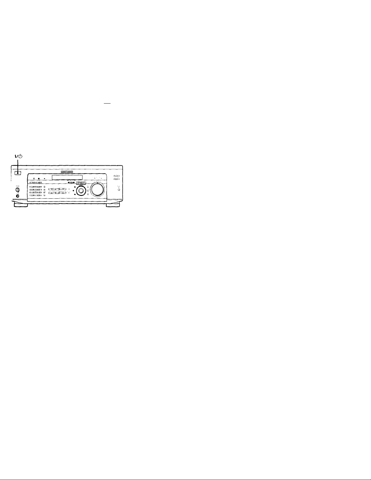
To cancel the demonstration
Press l/(!) to turn the receiver off during the previous
message. The next time you turn the receiver on, the
demonstration will not appear.
To view the demonstration
Hold down SET UP and press 1/(1) to turn on the power.
Note
Running the demonstration will clear the receiver’s
memory. For details on what will be cleared, see «Clearing
the receiver’s memory» on page 15.
Receiving Broadcasts 39
Direct Tuning 40
Automatic Tuning 41
Preset Tuning 41
Other Operations 43
Naming Preset Stations and Program Sources 44
Recording 44
Using the Sleep Timer 45
Adjustment Using the SET UP Button 46
Additional information 47
Troubleshooting 47
Specifications 49
Glossary 51
Tables of Settings Using SUR, LEVEL, EQ, and
SET UP buttons 52
Index (Back cover)

Hooking Up
the
Components
This chapter describes how to connect
various audio and video components
to the receiver. Be sure to read the
sections for the components you have
before you actually connect them to
the receiver.
Unpacking
Chock that ’ou received the tollowing items with the
remote;
• F’M wire antenna (n
• AM loop antenna (1)
• Remote commander RM-PP402 (remote) (1)
• R6 (size-AA) batteries (2)
• FM antenna adapter (1)
Inserting batteries into the remote
Insert R6 (sizo-AA) batteries with the + and — properly
oriented in the battery compartment. When using the
remote, point it at the remote sensor H on the receiver.
For details, refer to the operating instructions supplied
with your remote.
? When to replace batteries
Under normal conditions, the batteries should last tor about 6
months. When the remote no longer operates the receiver, replace
all batteries with new ones.
Notes
• Do not leave the remote in an extremely hot or humid place.
• Do not use a new battery with an old one.
• Do not expose the remote sensor to direct sunlight or lighting
apparatuses. Doing so may cause a malfunction.
• If you don’t use the remote for an extended period of time,
remove the batteries to avoid possible damage from battery
leakage and corrosion.
Before you get started
• Turn off the power to all components before making
any connections.
• Do not connect the AC power cords until all of the
connections are completed.
• Be sure to make connections firmly to avoid hum and
noise.
• When connecting an audio / video cord, be sure to
match the color-coded pins to the appropriate jacks on
the components: yellow (video) to yellow; white (left,
audio) to white; and red (right, audio) to red.
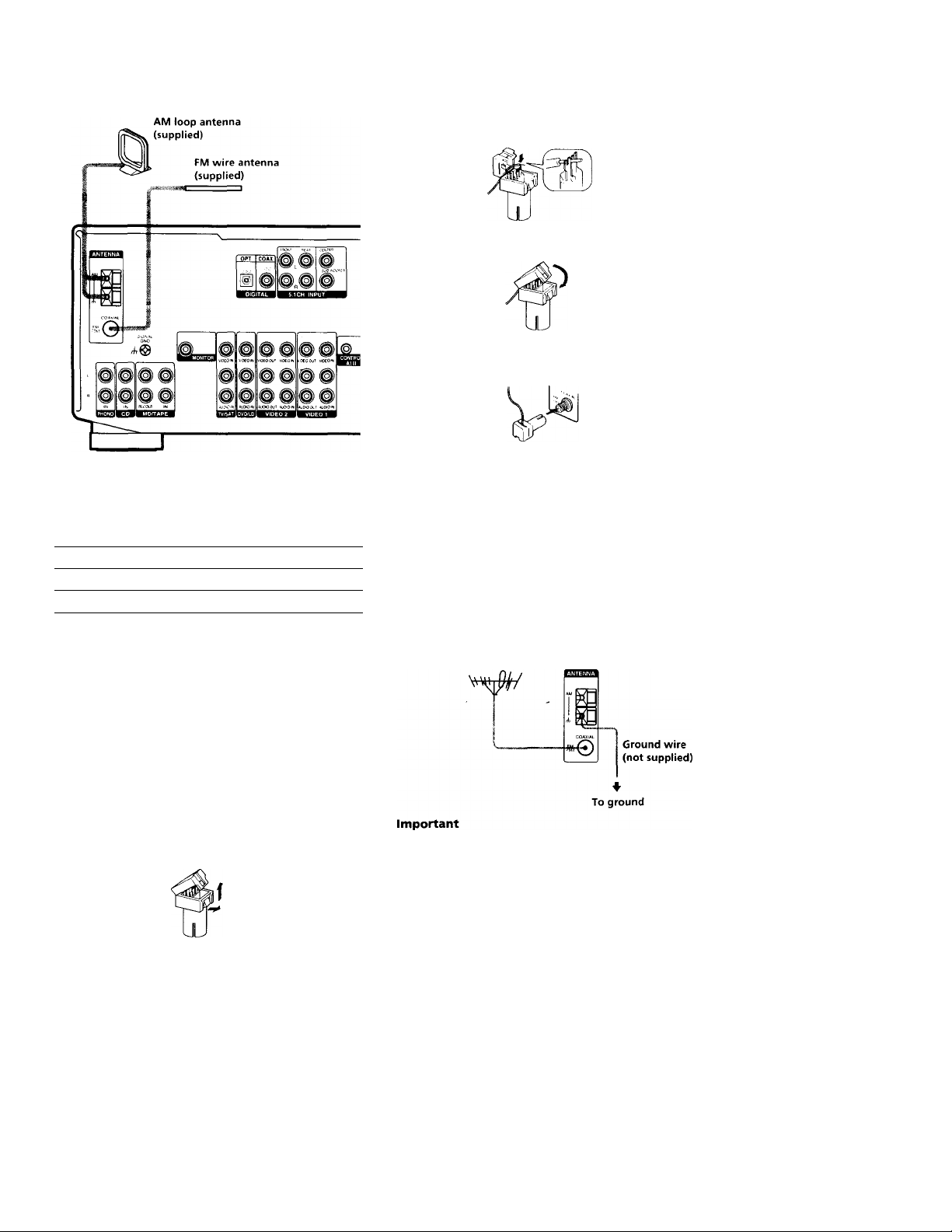
Antenna Hookups
3 Insert wire antenna into adaptor and wedge
stripped end between the forks in the adaptor.
4 Close the adaptor.
5 Attach the adaptor to the FM antenna terminal.
0
0
5’
(Q
C
■ D
f*
3-
o
n
o
3
■ o
o
3
ib
3
Terminals for connecting the antennas
Connect the
To the
AM loop antenna
AM terminals
FM wire antenna
FM 75Q COAXIAL terminal
Assembling the supplied FM antenna
The supplied FM wire antenna must be connected to the
supplied FM antenna adaptor.
1 Strip insulation off one end of the wire antenna.
5-7 mm
2 Open the antenna adaptor.
Pull up on the tab and pull the back away.
Notes on antenna hookups
• To prevent noise pickup, keep the AM loop antenna
away from the receiver and other components.
• Be sure to fully extend the FM wire antenna.
• After connecting the FM wire antenna, keep it as
horizontal as possible.
Q If you have poor FM reception
Use a 75-ohm coaxial cable (not supplied) to connect the receiver
to an outdoor FM antenna as shown below.
Outdoor FM antenna Receiver
If you connect the receiver to an outdoor antenna, ground
it against lightning. To prevent a gas explosion, do not
connect the ground wire to a gas pipe.
Note
Do not use the SIGNAL GND A terminal tor grounding the
receiver.
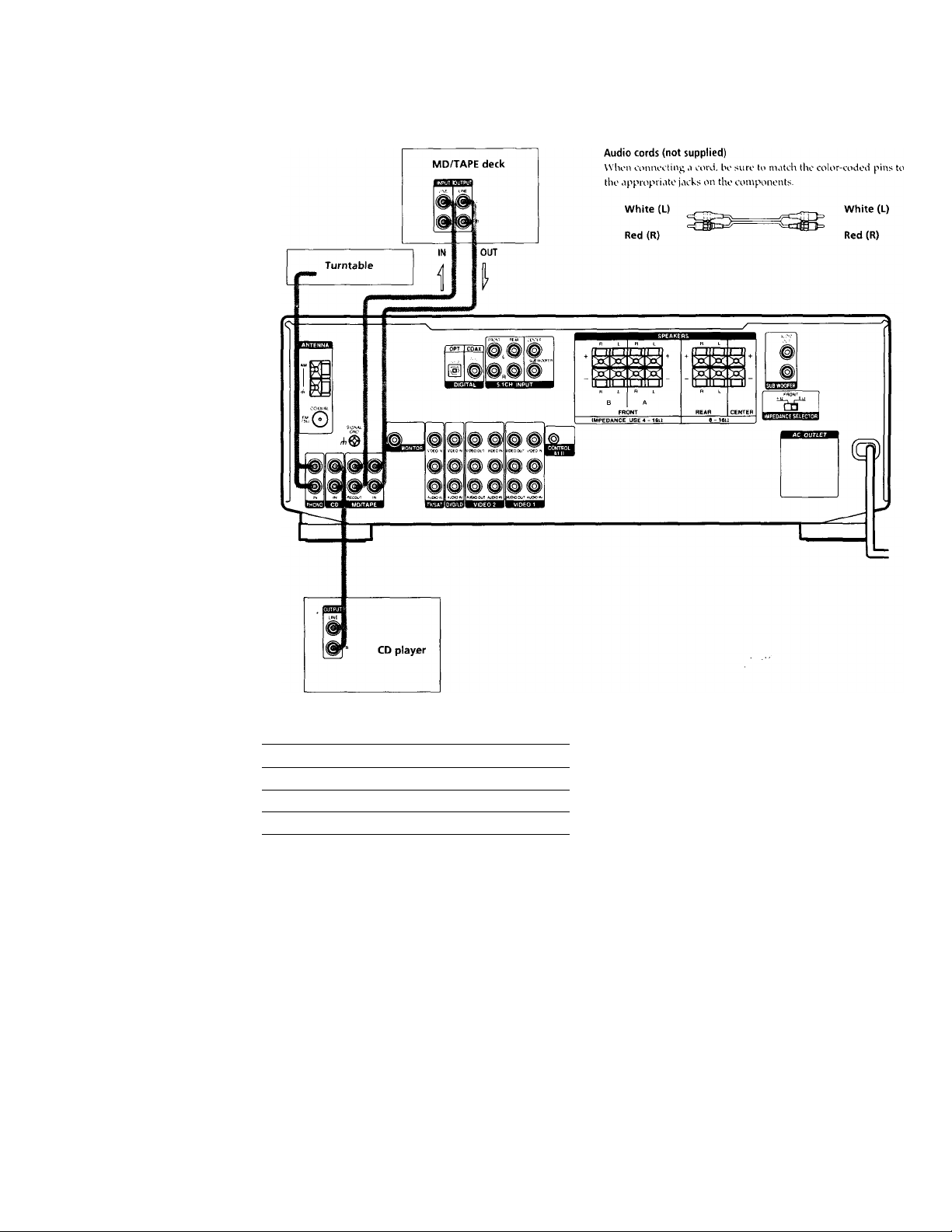
Audio Component Hookups
Required cords
Jacks for connecting audio components
Connect a To the
Turntable PHONO jacks
CD player
CD jacks
MD deck or Tape deck
MD/TAPE jacks
Note on audio component hookups
If your turntable has a ground wire, connect it to the
ih SIGNAL GND terminal on the receiver.
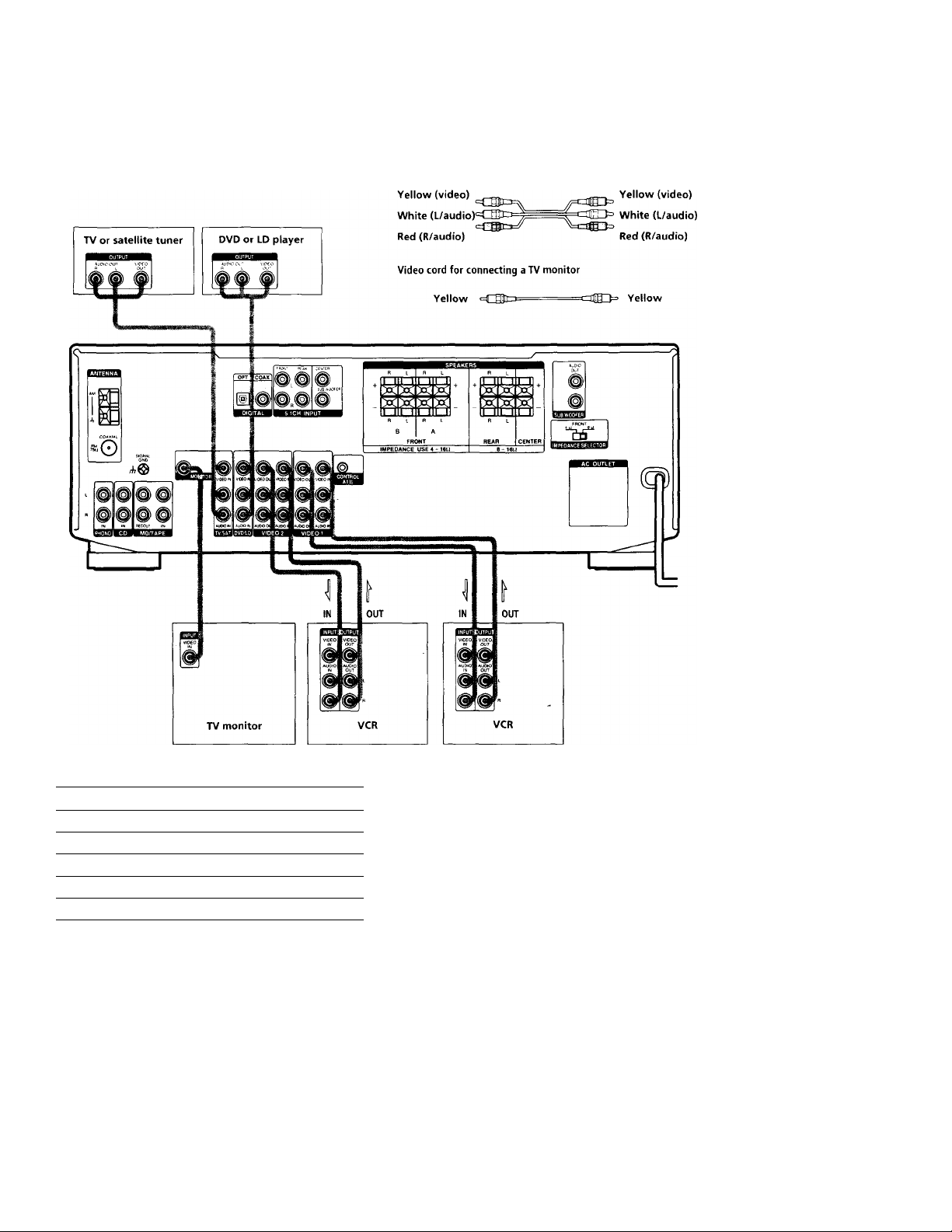
Video Component Hookups
Audio/video cords (not supplied)
Wlion connoctiiig CÌ cord, bo suro to match tho color-codod pins to
the appropriato jacks on ilio conipononts.
Required cords
X
o
o
5;
5’
(Q
C
■ D
y
A
n
O
3
■ a
o
3
«
3
Jacks for connecting video components
Connect a To the
TV or satellite tuner TV/SAT jacks
VCR VIDEO 1 jacks
Additional VCR
VIDEO 2 jacks
DVD or LD player DVD/LD jacks
TV monitor MONITOR VIDEO OUT jack
Note on video component hookups
You can connect your TV’s audio output jacks to the TV/
SAT AUDIO IN jacks on the receiver and apply sound
effects to the audio from the TV. In this case, do not
connect the TV’s video output jack to the TV/SAT VIDEO
IN jack on the receiver. If you are connecting a separate
TV tuner (or satellite tuner), connect both the audio and
video output jacks to the receiver as shown above.
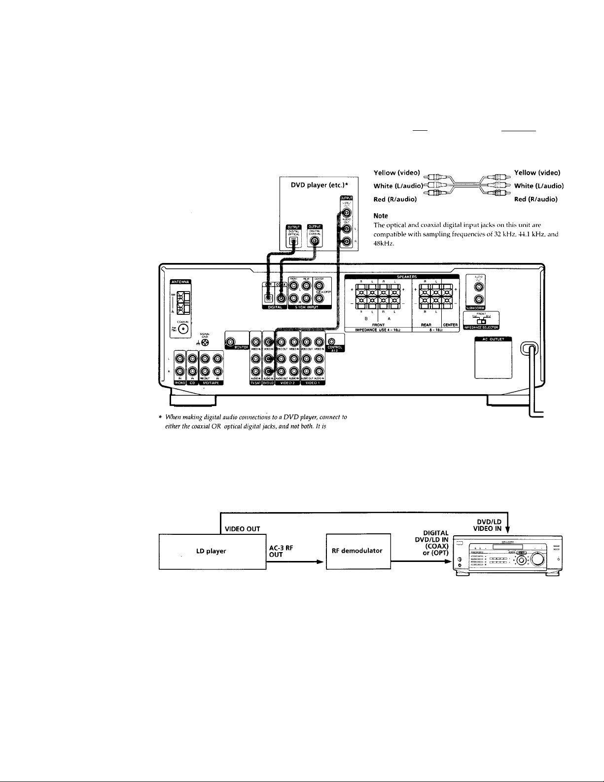
Digital Component Hookups
Connect the digital output jacks ot vour DVD plaver (etc.)
to the receiver’s digital input jacks to bring the multi
channel surround sound ot a movie theater into our
home. To enjov tull ettect ot multi channel surround
sound, five speakers (two tront speakers, two rear
speakers, and a center speaker) and a sub wooter are
required. You can also connect an LD player with an RF
OUT jack ‘ia an RF demodulator, like the Sonv MOD-RFl
(not supplied).
Required cords
Optical digital cords (not supplied)
Black
Black
Coaxial digital cord (not supplied)
Yellow lililí^
=011111 0» Yellow
Audio/video cords (not supplied)
Wlien amnccting a cord, be sure to niatch the color-coded pins to
the appropriate jacks on the components.
recommended to make digital audio connections to the coaxial jack.
Example of LD player connected via an RF demodulator
Please note that you cannot connect an LD player’s AC-3 RF OUT jack directly to this unit’s digital input jacks. You must
first convert the RF signal to either an optical or coaxial digital signal. Connect the LD player to the RF demodulator, then
connect the RF demodulator’s optical or coaxial digital output to this unit’s OPTICAL or COAXIAL DVD/LD IN jack.
Refer to the instruction manual supplied with your RF Demodulator for details on AC-3 RF hookups.
Note
When making connections as shown above, be sure to set INPUT MODE ([^ on page 23) manually. This unit may not operate correctly if
INPUT MODE is set to «AUTO.»

5.1CH Input Hookups
Although this receiver incorporates a multi channel
decoder, it is also equipped with 5.1CH INPUT jacks.
These connections allow vou to enjoy multichannel
software encoded in formats other than Dolb- Digital
(AC-3). If vour DVD player is equipped with 5. ICH
OUTPUT jacks, you can connect them directly to this unit
to enjoy the sound of the DVD player’s multi channel
decoder. Alternatively, the 5.ICH INPUT jacks can be
used to connect an external multi channel decoder.
To fully enjoy multi channel surround sound, you will
need five speakers (two front speakers, two rear speakers,
and a center speaker) and a sub woofer. Refer to the
instruction manual supplied with your DVD player, multi
channel decoder, etc., for details on the 5.1 channel input
hookups.
Audio cords (not supplied)
Two tor the ICH INPUT FRONT and REAR jacks
Required cords
White (L)
Red (R)
White (L)
Red (R)
Monaural audio cords (not supplied)
Two for the 5. ICH INPUT CENTER and WOOFER jacks
Black
Black
0
0
x;
5′
ifi
c
“D
T
<6
n
0
3
TJ
0
3
10
3
Video cord (not supplied)
One for the DVD / LD VIDEO IN jacks (etc.)
DVD player.
Multichannel decoder, etc.
Yellow gf~Elto=
=czag3= Yellow
Note
When using the connections described below, adjust the level of
your surround speakers and sub woofer from the DVD player or
multichannel decoder.
Example of a DVD player hookup using the 5.1 INPUT jacks
-[ ~| Front Speaker (L)
-[ j Front Speaker (R)
Rear Speaker (L)
j Rear Speaker (R)
-[ ] Center Speaker
Active Woofer
See page 15 for details on speaker system hookup.
other Hookups
X
0
0
5*
Q
c
9
T
i
Required cords
Control A1 connecting cord (not supplied)
Black «cr^JnsE
CONTROL A1 11
Black
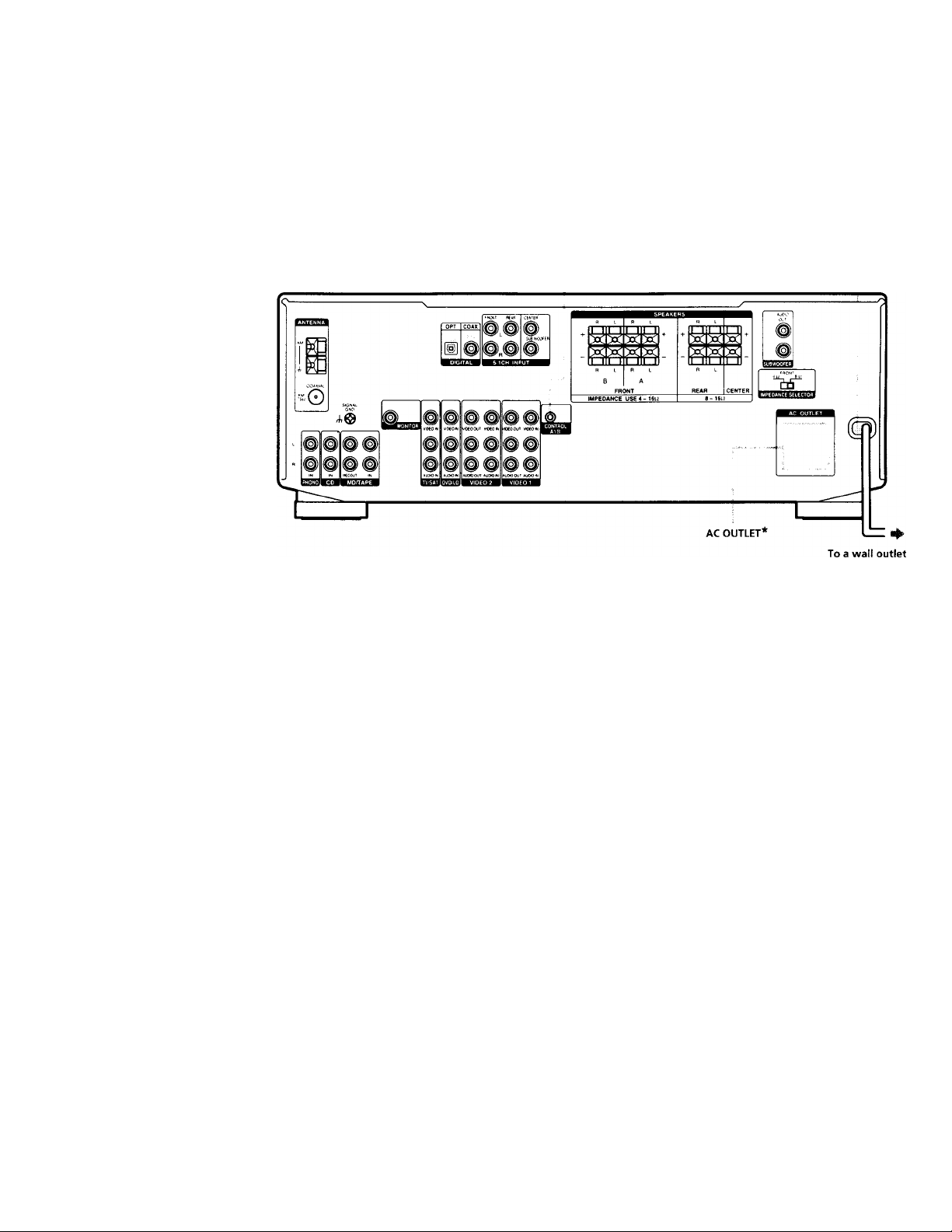
AC power cord
The configuration, shape, and number of AC outlets on the rear panel
varies according to the model and country to which the receiver is
shipped.
10

CONTROL A1 II hookup
• If you have a CONTROL A1 ll compatible Sony
CD player, tape deck, or MD deck
Use a CONTROL A1 cord (not supplied) to connect the
CONTROL A1 or CONTROL A1 II jack on the CD
player, tape deck, or MD deck to the CONTROL A1 II
jack on the receiver. Refer to the separate manual
«CONTROL-Al II Control System» and the operating
instructions supplied with your CD player, tape deck,
or MD deck for details.
Note
If you make CONTROL A1 II connections from the receiver to
an MD deck that is also connected to a computer, do not
op>erate the receiver while using the «Sony MD Editor»
software. This may cause a malfunction.
• If you have a Sony CD changer with a
COMMAND MODE selector
If your CD changer’s COMMAND MODE selector can
be set to CD 1, CD 2, or CD 3, be sure to set the
command mode to «CD 1» and connect the changer to
the CD jacks on the receiver.
If, however, you have a Sony CD changer with VIDEO
OUT jacks, set the command mode to «CD 2» and
connect the changer to the VIDEO 2 jacks on the
receiver.
Connecting the AC power cord
Before connecting the AC power cord of this receiver to a
wall outlet:
• Connect the speaker system to the receiver (see page
13).
• Turn the MASTER VOLUME control to the leftmost
position (0).
Connect the AC power cord(s) of your audio/video
components to a wall outlet.
If you connect other audio/video components to the AC
OUTLET(s) on the receiver, the receiver will supply power
to the connected component(s), allowing you to turn the
whole system on or off when you turn the receiver on or
off.
Caution
Make sure that the total power consumption of the component(s)
connected to the receiver’s AC OUTLET(s) does not exceed the
wattage stated on the rear panel. Do not connect high-wattage
electrical home appliances such as electric irons, fans, or TVs to
this outlet.
Note
If the AC power cord is disconnected for about two weeks, the
receiver’s entire memory will be cleared and the demonstration
will start.
0
0
?r
5*
c
■ o
n
o
3
■ o
o
3
m
3
11
Hooking Up
and Setting Up
the Speaker
System
This chapter describes how to hook
up your speaker system to the
receiver, how to position each speaker,
and how to set up your speakers to
enjoy multi channel surround sound.
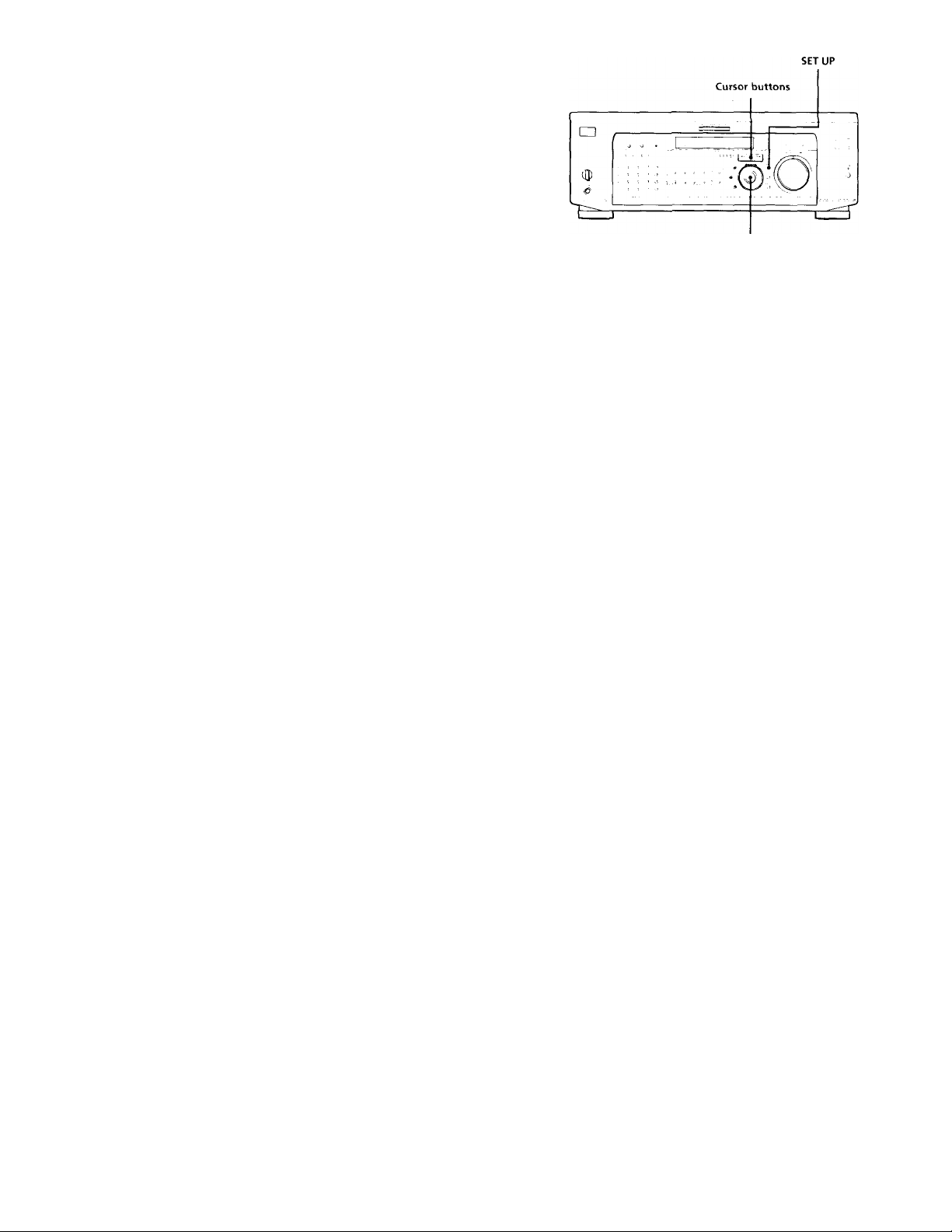
Jog dial
Brief descriptions of buttons and control
used to set up the speaker system
SET UP button: Press to enter the setup mode when
specifying speaker types and distances.
Cursor buttons (</»: Use to select parameters after
pressing the SET UP button.
Jog dial; Use to adjust the setting of each parameter.
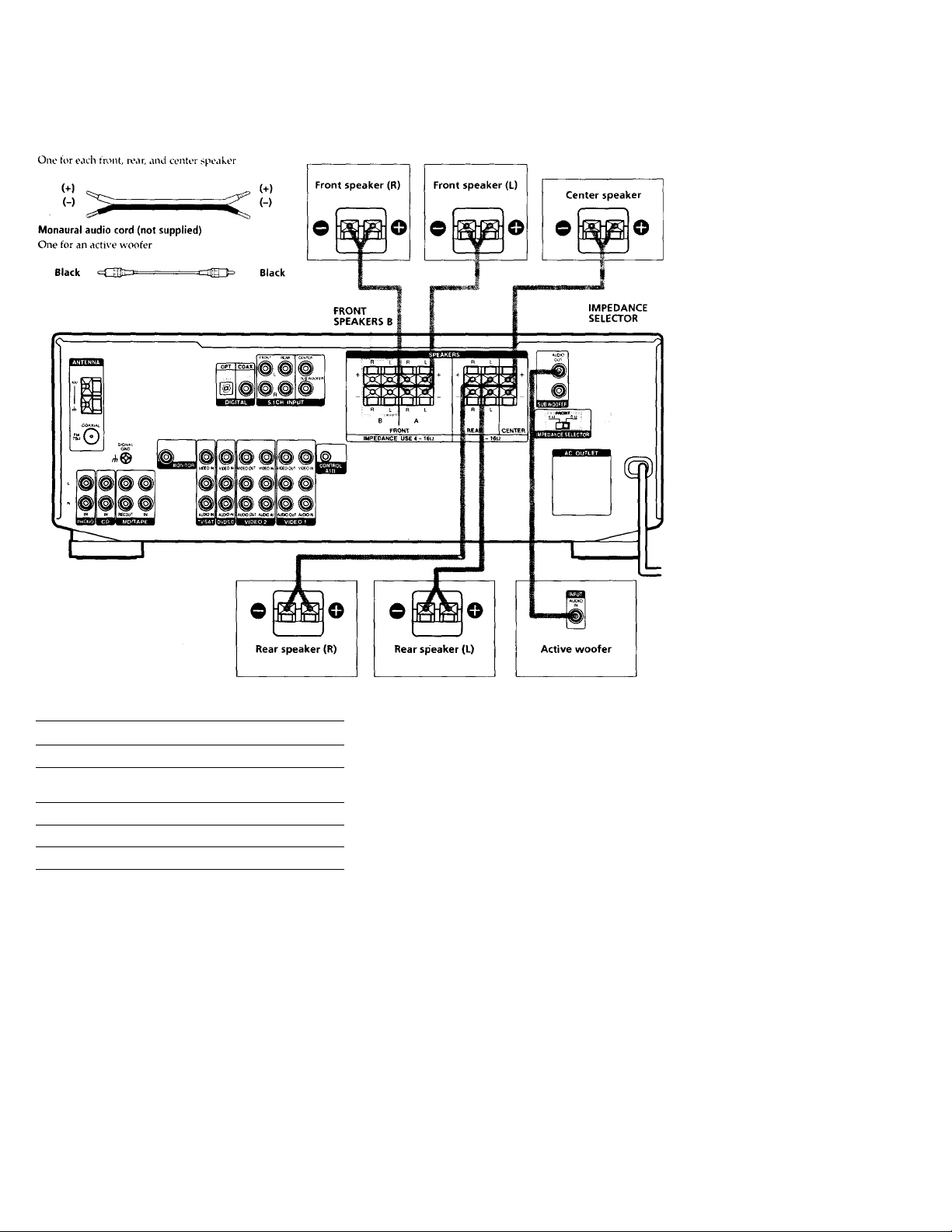
Speaker System Hookup
Required cords
Speaker cords (not supplied)
0
0
x;
5’
ua
c
■ o
fi)
3
fi.
(/I
o
3
<fi
c
•c
3-
o
(A
•o
(fi
fi)
jr
(fi
n
i/1
»<
Vi
(fi
3
Terminals for connecting the speakers
Connect the
To the
Front speakers (8 or 4* ohm)
SPEAKERS FRONT A terminals
Additional pair of front
speakers (8 or 4* ohm)
SPEAKERS FRONT B terminals
Rear speakers (8 ohm) SPEAKERS REAR terminals
Center speaker (8 ohm)
SPEAKERS CENTER terminals
Active sub woofer
SUB WOOFER AUDIO OUT jack**
See «Speaker impedance» on the next page.
* You can connect an active sub woofer to either of the two jacks. The
remaining jack can be used to connect a second active sub woofer.
Notes on speaker system hookup
• Twist the stripped ends of the speaker cords about 2/3
inch (10 mm). Be sure to match the speaker cord to the
appropriate terminal on the components: + to + and —
to If the cords are reversed, the sound will be
distorted and will lack bass.
• If you use front speakers with low maximum input
rating, adjust the volume carefully to avoid excessive
output on the speakers.
13
Speaker System Hookup
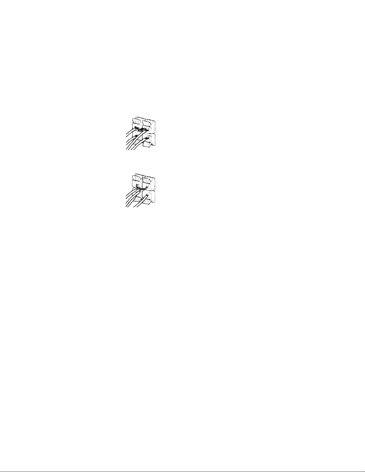
To avoid short-circuiting the speakers
ihort-circuitinj; of the speakers may ciamage the receiver.
To prevent this, make sure to take the following
precautions when connecting the speakers.
Make sure the stripped ends of each speaker cord
ioes not touch another speaker terminal or the
tripped end of another speaker cord.
Speaker impedance
To enjov multi channel surround, connect front, center,
and rear speakers with a nominal impedance of 8 ohms or
higher, and set tire speaker IMPEDANCE SELECTOR to
«8D.» Check the instruction manual supplied with your
speakers if you’re not sure of their impedance. (This
information is usually printed on a label on the back of
the speaker.)
xamples of poor conditions of the speaker cord
ripped speaker cord is touching another speaker terminal.
pped cords are touching each other due to excessive
loval of insulation.
:er connecting all the components, speakers,
I AC power cord, output a test tone to check
t all the speakers are connected correctly. For
ails on outputting a test tone, see page 18.
You may connect a pair of speakers with a nominal
impedance between 4 and 8 ohms to the FRONT
SPEAKERS terminals, if you set the IMPEDANCE
SELECTOR to Speakers connected to the REAR and
CENTER SPEAKERS terminals must have a nominal
impedance of 8 ohms or higher (regardless of the setting
of the IMPEDANCE SELECTOR).
Note
Be sure to connect front speakers with a nominal impedance of 8
ohms or higher if you want to select both sets (A+B) of front
speakers (see page 23).
1 sound is heard from a speaker while outputting a
tone or a test tone is output from a speaker other than
>ne whose name is currently displayed on the
ver, the speaker may be short-circuited. If this
>ens, check the speaker connection again.
Performing Initial Setup Operations
Jnce you have made speaker connections and have
urned on the power for the first time, clear the memorv.
fter you have done this, set the speaker sizes, speaker
ocations and whate’er other initial s’stem settings are
lecessary.
Before turning on the receiver
vfake sure that you have:
* Turned MASTER VOLUME to the leftmost position (0).
* Selected the appropriate front speakers (see »l
SPEAKERS selector» on page 23).
Clearing the receiver’s memory
•efore you use your receiver for the first time or when
ou want to clear the receiver’s memory, do the following,
his procedure is not necessary if the demonstration
ctivates when you turn the power on.
Performing initial setup operations
Before )’ou use your receiver for the first time, use the SET
UP button to adjust settings to correspond to your system.
You can set the following items. For details on how to
adjust each setting, see the page in parethesis.
• Speaker size and placement (page 16).
• Speaker distance (page 18).
• The video signal paired with the 5.1CH INPUT (page
46).
• Whether other components will turn on and off via the
CONTROL A1 II control system (page 46).
X
0
o
*■
s’
(Q
c
*D
3
a
VI
5
5’
(fi
c
•o
A
VI
*0
№
0)
JT
ft
V)
<
ft
3
Turn off the receiver.
Hold down l/d) for 5 seconds.
The currently selected function, then the
demonstration message appears in the display and the
items including the following are reset or cleared:
• All preset stations are reset or cleared.
• All sound field parameters are reset to their factory
settings.
• All index names (of preset stations and program
sources) are cleared.
• All adjustments made with the SET UP button are
reset to their factory settings.
• The sound field memorized for each program source
and preset stations are cleared.
15
Multi Channel Surround
Setup
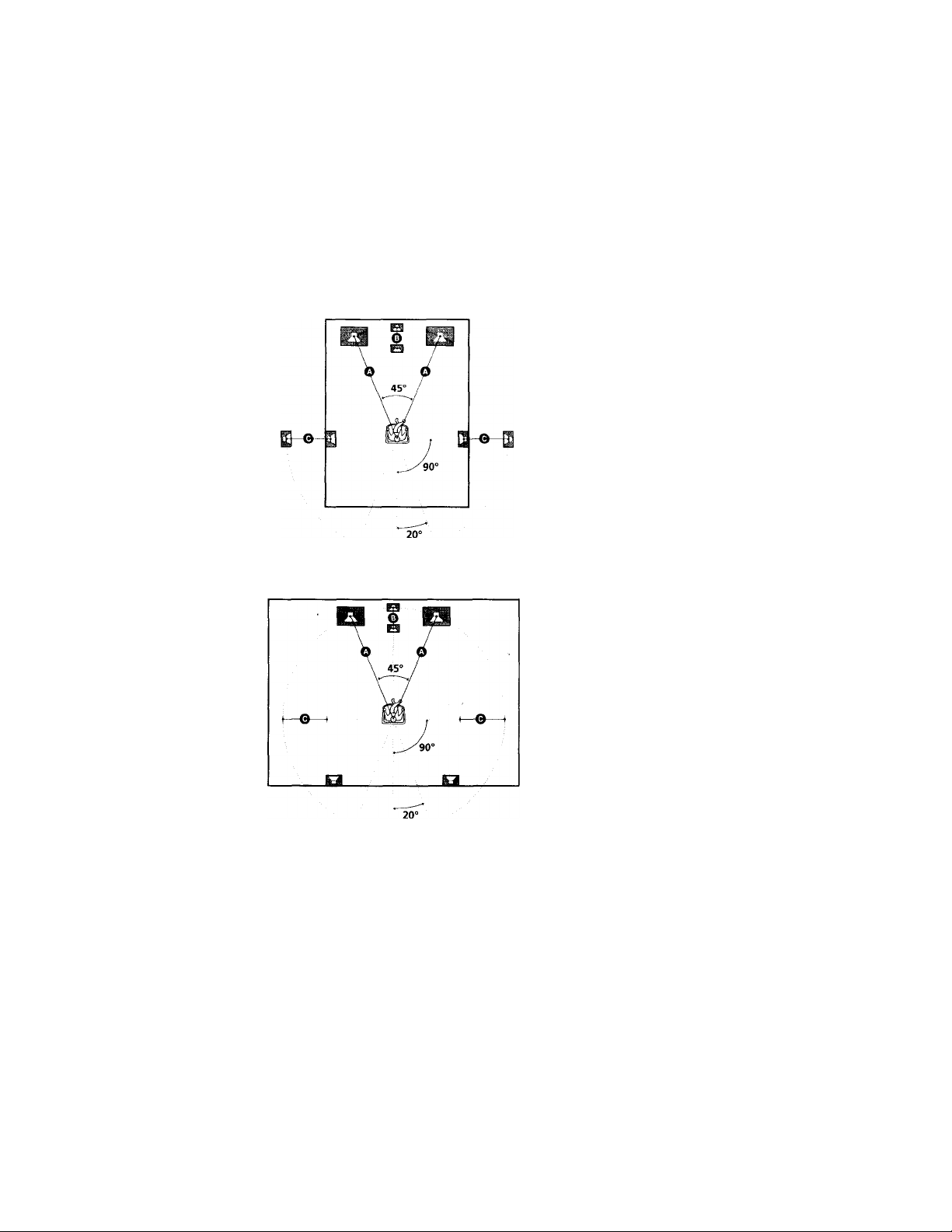
For the best possible surround sound all speakers should
be the same distance from the listening position (O)
(However, this unit lets vou to place the center speaker up
to 5 feet (1.5 meters) closer (©) and the rear speakers up
to 15 feet (4.5 meters) closer (©) to the listening position.
The front speakers can be placed from 3 to 40 feet (1.0 to
12.0 meters) from the listening position {©).)
You can place the rear speakers either behind ou or to
the side, depending on the shape of vour room (etc.).
When placing rear speakers to your side
Specifying the speaker parameters
1 Press l/c!) to turn on the receiver.
2 Press SET UP.
3 Press the cursor buttons (< or »to select the
parameter you want to adjust.
4 Turn the jog dial to select setting you desire. The
setting is entered automatically.
5 Repeat steps 3 and 4 until you have set all of the
parameters that follow.
■ Front speaker size (FRONT)
Initial setting ; LARGE
• If you connect large speakers that will effectively
reproduce bass frequencies, select «LARGE». Normally,
select «LARGE».
• If the sound is distorted, or you feel a lack of surround
effects when using multi channel surround sound,
select «SMALL» to activate the bass redirection circuitry
and output the front channel bass frequencies from the
sub woofer.
• When the front speaker is set to «SMALL», the center
and rear speakers are also automatically set to
«SMALL» (unless previously set to «NO»).
When placing the rear speakers behind you
Note
Do not place the center speaker farther away from the listening
position than the front speakers.
16
 Loading…