Контрольно-измерительные приборы
Технические характеристики
Прибор СПА-2
Также этот прибор может называться: СПА2, СПА 2.
СПА-2 является прибором магнитоэлектрической системы.
Приборы выполнены в металлическом корпусе.
Технические характеристики СПА-2:
Основная погрешность, выраженная в процентах от конечного значения диапазона измерений — 4,0%.
Тип тока — переменный; постоянный.
Тип измерений — внутренние; внешние.
Диапазоны — от 0 до 10 АВ; от 0 до 30 АВ.
Испытательное напряжение — 2 кВ.
Принадлежности — выпрямители.
Рабочее положение — вертикальное.
Регулировка выходного напряжения и тока.
Возможность подключения секундомера и вентилятора.
Габаритные размеры — 300х200х380 мм.
Масса СПА-2 — не более 18,1 кг.
Изготовитель гарантирует соответствие приборов СПА-2 требованиям действующих технических условий при соблюдении условий эксплуатации, транспортирования и хранения.
Вся текстовая и графическая информация на сайте несет информативный характер. Цвет, оттенок, материал, геометрические размеры, вес, содержание, комплект поставки и другие параметры товара представленого на сайте могут изменяться в зависимости от партии производства и года изготовления. Более подробную информацию уточняйте в отделе продаж.
Ведущий интернет-магазин Западприбор — это огромный выбор измерительного оборудования по лучшему соотношению цена и качество. Чтобы Вы могли купить приборы недорого, мы проводим мониторинг цен конкурентов и всегда готовы предложить более низкую цену. Мы продаем только качественные товары по самым лучшим ценам. На нашем сайте Вы можете дешево купить как последние новинки, так и проверенные временем приборы от лучших производителей.
На сайте постоянно действует акция «Куплю по лучшей цене» — если на другом интернет-ресурсе (доска объявлений, форум, или объявление другого онлайн-сервиса) у товара, представленного на нашем сайте, меньшая цена, то мы продадим Вам его еще дешевле! Покупателям также предоставляется дополнительная скидка за оставленный отзыв или фотографии применения наших товаров.
В прайс-листе указана не вся номенклатура предлагаемой продукции. Цены на товары, не вошедшие в прайс-лист можете узнать, связавшись с менеджерами. Также у наших менеджеров Вы можете получить подробную информацию о том, как дешево и выгодно купить измерительные приборы оптом и в розницу. Телефон и электронная почта для консультаций по вопросам приобретения, доставки или получения скидки приведены возле описания товара. У нас самые квалифицированные сотрудники, качественное оборудование и выгодная цена.
Интернет магазин Западприбор — официальный дилер заводов изготовителей измерительного оборудования. Наша цель — продажа товаров высокого качества с лучшими ценовыми предложениями и сервисом для наших клиентов. Наш интернет магазинможет не только продать необходимый Вам прибор, но и предложить дополнительные услуги по его поверке, ремонту и монтажу. Чтобы у Вас остались приятные впечатления после покупки на нашем сайте, мы предусмотрели специальные гарантированные подарки к самым популярным товарам.
Вы можете оставить отзывы на приобретенный у нас прибор, измеритель, устройство, индикатор или изделие. Ваш отзыв при Вашем согласии будет опубликован на официальном сайте без указания контактной информации.
Интернет-магазин принимаем активное участие в таких процедурах как электронные торги, тендер, аукцион.
При отсутствии на официальном сайте в техническом описании необходимой Вам информации о приборе Вы всегда можете обратиться к нам за помощью. Наши квалифицированные менеджеры уточнят для Вас технические характеристики на прибор из его технической документации: инструкция по эксплуатации, паспорт, формуляр, руководство по эксплуатации, схемы. При необходимости мы сделаем фотографии интересующего вас прибора, стенда или устройства.
Описание на приборы взято с технической документации или с технической литературы. Большинство фото изделий сделаны непосредственно нашими специалистами перед отгрузкой товара. В описании устройства предоставлены основные технические характеристики приборов: номинал, диапазон измерения, класс точности, шкала, напряжение питания, габариты (размер), вес. Если на сайте Вы увидели несоответствие названия прибора (модель) техническим характеристикам, фото или прикрепленным документам — сообщите об этом нам — Вы получите полезный подарок вместе с покупаемым прибором.
При необходимости, уточнить общий вес и габариты или размер отдельной части измерителя Вы можете в нашем сервисном центре. Наши инженеры помогут подобрать полный аналог или наиболее подходящую замену на интересующий вас прибор. Все аналоги и замена будут протестированы в одной с наших лабораторий на полное соответствие Вашим требованиям.
Основная особенность нашего интернет магазина проведение объективных консультаций при выборе необходимого оборудования. У нас работают около 20 высококвалифицированных специалистов, которые готовы ответить на все ваши вопросы.
В технической документации на каждый прибор или изделие указывается информация по перечню и количеству содержания драгметаллов. В документации приводится точная масса в граммах содержания драгоценных металлов: золото Au, палладий Pd, платина Pt, серебро Ag, тантал Ta и другие металлы платиновой группы (МПГ) на единицу изделия. Данные драгметаллы находятся в природе в очень ограниченном количестве и поэтому имеют столь высокую цену. У нас на сайте Вы можете ознакомиться с техническими характеристиками приборов и получить сведения о содержании драгметаллов в приборах и радиодеталях производства СССР. Обращаем ваше внимание, что часто реальное содержание драгметаллов на 10-25% отличается от справочного в меньшую сторону! Цена драгметаллов будет зависить от их ценности и массы в граммах.
Мы предлагаем быструю международную доставку практически во все страны мира: Австралия (Australia), Австрия (Austria), Азербайджан, Албания (Albania), Алжир (Algeria), Ангилья, Ангола, Антигуа и Барбуда, Аргентина (Argentina), Аруба, Багамские острова, Бангладеш, Барбадос, Бахрейн, Белиз, Бельгия (Belgium), Бенин, Бермуды, Болгария (Bulgaria), Боливия, Бонайре, Синт-Э. и Саба, Босния и Герцеговина (Bosnia and Herzegovina), Ботсвана, Бразилия (Brazil), Британские Виргинские Острова, Бруней Даруссалам, Буркина Фасо, Бурунди, Бутан, Вьетнам (Vietnam), Вануату, Ватикан, Венесуэла, Армения, Габон, Гайана, Гаити, Гамия, Гамбия, Гана, Гватемала, Гвинея, Гибралтар, Гондурас, Гонконг, Гренада, Гренландия (Greenland), Греция (Greece), Грузия (Georgia), Дания (Denmark), Демократическая Республика Конго, Джерси, Джибути, Доминика, Доминиканская Республика, Эквадор, Эсватин, Эстония (Estonia), Эфиопия (Ethiopia), Египет (Egypt), Замбия, Зимбабве (Zimbabwe), Иордания Индонезия, Ирландия (Ireland), Исландия (Iceland), Испания (Spain), Италия (Italy), Кабо-Верде, Казахстан (Kazakhstan), Каймановы острова, Камбоджа, Камерун, Канада (Canada), Катар, Кения, Кыргызстан, Китай (China), Кипр (Cyprus), Кирибати, Колумбия (Colombia), Коморские острова, Конго, Корея (Республика) (Korea Rep.), Коста-Рика, Кот-д’Ивуар, Куба, Кувейт, Кюрасао, Лаос, Латвия (Latvia), Лесото, Литва (Lithuania), Либерия, Ливан, Ливия, Лихтенштейн, Люксембург, Мьянма, Маврикий, Мавритания, Мадагаскар, Макао, Малави, Малайзия, Мали, Мальдивы, Мальта, Марокко (Morocco), Мексика (Mexico), Мозамбик, Молдова (Moldova), Монако, Монако, Намибия, Науру, Непал, Нигер, Нигерия (Nigeria), Нидерланды (Netherlands), Германия (Germany), Новая Зеландия (New Zealand), Новая Каледония, Норвегия (Norway), ОАЭ (UAE), Оман, Острова Кука, Пакистан, Палестина, Панама, Папуа Новая Гвинея, Парагвай, Перу, Южная Африка, Польша (Poland), Португалия (Portugal), Республика Чад, Руанда, Румыния (Romania), Сальвадор, Самоа, Сан-Марино, Саудовская Аравия (Saudi Arabia), Свазиленд, Сейшельские острова, Сенегал, Сент-Винсент и Гренадины, Сент-Китс и Невис, Сент-Люсия, Сербия (Serbia), Сингапур (Singapore), Синт-Мартен, Словакия (Slovakia), Словения (Slovenia), Соломоновые острова, Соединенное Королевство Великобритании и Северной Ирландии (United Kingdom of Great Britain and Northern Ireland), Судан, Суринам, Восточный Тимор (Тимор-Лешти), США (USA), Сьерра-Леоне, Таджикистан, Тайвань (Taiwan), Таиланд (Thailand), Танзания (Объединенная Республика), Того, Тонга, Тринидад и Тобаго, Тувалу, Тунис (Tunisia), Турция (Turkey), Туркменистан, Уганда, Венгрия (Hungary), Узбекистан, Уругвай, Фарерские острова, Фиджи, Филиппины (Philippines), Финляндия (Finland), Франция (France), Французская Полинезия, Хорватия (Croatia), Центральноафриканская Республика, Чешская Республика (Czech Republic), Чили, Черногория (Montenegro), Швейцария (Switzerland), Швеция (Sweden), Шри-Ланка, Ямайка, Япония (Japan).
Иногда клиенты могут вводить название нашего интернет магазина или официальный сайт неправильно — например, западпрыбор, западпрылад, западпрібор, западприлад, західприбор, західпрібор, захидприбор, захидприлад, захидпрібор, захидпрыбор, захидпрылад. Правильно — западприбор.
Наш технический отдел осуществляет ремонт и сервисное обслуживание измерительной техники более чем 75 разных заводов производителей бывшего СССР и СНГ. Также мы осуществляем такие метрологические процедуры: калибровка, тарирование, градуирование, испытание средств измерительной техники.
Если Вы можете сделать ремонт устройства самостоятельно, то наши инженеры могут предоставить Вам полный комплект необходимой технической документации: электрическая схема, ТО, РЭ, ФО, ПС. Также мы располагаем обширной базой технических и метрологических документов: технические условия (ТУ), техническое задание (ТЗ), ГОСТ, отраслевой стандарт (ОСТ), методика поверки, методика аттестации, поверочная схема для более чем 3500 типов измерительной техники от производителя данного оборудования. Из сайта Вы можете скачать весь необходимый софт (программа, драйвер) необходимый для работы приобретенного устройства.
Также у нас есть библиотека нормативно-правовых документов, которые связаны с нашей сферой деятельности: закон, кодекс, постановление, указ, временное положение.
СПА-2
Прибор СПА-2
Также этот прибор может называться: СПА2, СПА 2.
СПА-2 является прибором магнитоэлектрической системы.
Приборы выполнены в металлическом корпусе.
Технические характеристики СПА-2:
Основная погрешность, выраженная в процентах от конечного значения диапазона измерений — 4,0%.
Тип тока — переменный; постоянный.
Тип измерений — внутренние; внешние.
Диапазоны — от 0 до 10 АВ; от 0 до 30 АВ.
Испытательное напряжение — 2 кВ.
Принадлежности — выпрямители.
Рабочее положение — вертикальное.
Регулировка выходного напряжения и тока.
Возможность подключения секундомера и вентилятора.
Габаритные размеры — 300х200х380 мм.
Масса СПА-2 — не более 18,1 кг.
Изготовитель гарантирует соответствие приборов СПА-2 требованиям действующих технических условий при соблюдении условий эксплуатации, транспортирования и хранения.
Предложите, как улучшить StudyLib
(Для жалоб на нарушения авторских прав, используйте
другую форму
)
Ваш е-мэйл
Заполните, если хотите получить ответ
Оцените наш проект
1
2
3
4
5
-
Contents
-
Table of Contents
-
Bookmarks
Quick Links
SPA-2
Snow pack analyzer
Manual
Setup version 3.10 (Firmware 2.20)
02 September, 2020
Sommer Messtechnik
All rights reserved.
Related Manuals for SOMMER SPA-2
Summary of Contents for SOMMER SPA-2
-
Page 1
SPA-2 Snow pack analyzer Manual Setup version 3.10 (Firmware 2.20) 02 September, 2020 Sommer Messtechnik All rights reserved. -
Page 2
6842 Koblach Austria This manual or parts of it may only be copied or passed on to third parties with written permission of Sommer Messtechnik. This applies to printed as well as digital issues of this manual. Sommer Messtechnik Strassenhäuser 27… -
Page 3
EN 62311:2008 EN 62368-1:2014 RoHS II 2011/65/EU RoHS III 2015/863/EU Feedback Should you come across any error in this manual, or if you miss information to handle and operate the SPA-2 we are very grateful for your feedback to office@sommer.at. -
Page 4
Prior to installation of equipment inform the owner of the measurement site or the authority responsible for it. Upon completion, secure the installation from trespassers. Maintenance and repair must be performed by trained personnel or an engineer of Sommer Messtechnik. Only replacement parts supplied by Sommer Messtechnik should be used for repairs. -
Page 5: Table Of Contents
Content What is the SPA-2? Unpacking How do I start? Connect the SPA-2 to a PC Configure the sensor Acquire measurements Specifications Connectors Terminals How does the SPA-2 work? Installation Where should I install the SPA-2? What do I need? How do I install the SPA-2? 7.3.1…
-
Page 6
Which commands are available? 11.5 Modbus 11.5.1 What is it? 11.5.2 What can I do with it? 11.5.3 How do I wire it? 11.5.4 How do I configure it? 11.5.5 How do I switch back to Sommer protocol? 11.5.6 Which commands are available? -
Page 7
Measurement trigger Measurement Interval Measurement table Snow depth adjust Snow depth test Technics Language/Sprache Decimal character Sleep mode Warm-up time Sommer ID SPA, sensor table SDI-12 service F-G-A SDI-12 address F-G-B SDI12 ‘M’-response F-G-C SDI-2 maximal duration F-G-D SDI-2 sensor search… -
Page 8
F-I-F OP, wake-up sequence F-I-G OP, prefix holdback F-I-H MODBUS, set default F-I-I MODBUS, device address RS-485-1 Port F-J-A Baud rate F-J-B Parity, stop bits F-J-C Minimum response time F-J-D Transmitter warm-up time F-J-E Flow control F-J-F Sending window F-J-G Receiving window Special functions Device status… -
Page 9: What Is The Spa-2
Determination of snowpack-properties can be very challenging as they vary significantly in space and time. The SPA-2 snow pack analyzer measures the volumetric contents of ice and water within a snowpack, and together with the snow depth calculates the snow water equivalent (SWE) and snow density.
-
Page 10: Unpacking
2 Unpacking When unpacking your SPA-2 sensor box please make sure that the following items are present: Name SPA-2 including assembly equipment Manual and Commander Software on USB stick The assembly equipment comprises the following parts: Description Quantity Base-profile right…
-
Page 11
Bolts and nuts are pre-mounted. In case of missing or damaged items please contact your Sommer sales partner. Available accessories Accessory 19294 USB to RS485 embedded converter cable, 1.8 m 20488 Commander software 20700 SPA-ribbon sensor set for horiz. 300-mm mounting; including tension spring and winch 20694 SPA-ribbon sensor set for horiz. -
Page 12: How Do I Start
7. Click Connect to establish a connection with the SPA-2. If the connection was successful a green icon is displayed at the top-right corner of the Commander window. 8. Select the tab…
-
Page 13: Configure The Sensor
3. Define the scope and structure of the data output (see General settings) Calibrate the SPA-2 by measuring the capacities of the ribbon sensors in air (see Calibration of SPA-2-ribbon-sensors) 5. Optional: measure the capacities of the ribbon sensors with a reference plate (see…
-
Page 14: Specifications
4 Specifications Physical and environmental Power supply 9…28 VDC; Reverse voltage protection, overvoltage protection Power consumption at max. 65 mA active 1mA in sleep mode 12 VDC Outputs RS-485 SDI-12 Analog output 4…20 mA (14 bit, max. load 200 Ω) Digital output (low: 0V, high: V , max.
-
Page 15
Inputs up to 4 SPA-sensors 4x Analog 0 … 2.5 V, 16 bit 2x Trigger input, low: 0…0.6 V, high: 2…26 V 1x RS-485 1x SDI-12 Outputs 4x Switched power supply (1 for snow depth sensor), max. 0.2 A each 1x RS-485 1x SDI-12 Measurement range and accuracy… -
Page 16: Connectors
5 Connectors Terminals All available connection terminals (Figure 3) are listed in the table below. ATTENTION Serial port BUS 2 is reserved for the USH-9 snow depth input! Figure 3 Connection terminals of SP-2 controller Terminal Description TRIG Trigger input 2 (not available) Ground Trigger input 1 Ground…
-
Page 17
Terminal Description BUS 1 RS-485 B (to data acquisition device) RS-485 A (to data acquisition device) SDI-12 (to data acquisition device) Ground Supply voltage (-) Supply voltage (-) Supply Voltage (+), 9.0 to 24.0 VDC Supply Voltage (+), 9.0 to 24.0 VDC Optional temperature input SPA-ribbon sensor 1 SPA-ribbon sensor 1… -
Page 18
Terminal Description Optional temperature input SPA-ribbon sensor 4 SPA-ribbon sensor 4 Shield of SPA-ribbon sensor 4 AIN 1,2 Ground Analog input 1 Ground Analog input 2 AIN 3,4 Ground Analog input 3 Ground Analog input 4 BUS 2 Ground SDI-12 (from sensor) RS-485 A (from USH-9) RS-485 B (from USH-9) OUT 1,2… -
Page 19
Terminal Description OUT 3,4 Ground Switched supply voltage 3 Ground Switched supply voltage 4 Table 1: Connection terminals of SP-2 controller Manual… -
Page 20: How Does The Spa-2 Work
The snow pack analyzer SPA-2 breaks this limitation and provides information about the snow pack by measuring the dielectric properties of a large snow volume. It provides all relevant snow properties like snow depth, snow density, snow water equivalent as well as the contents of liquid water and ice.
-
Page 21: Installation
3. There should be no boulders, trees, fences or other objects in the vicinity of the meas- urement spot. Any obstacle can cause snow drift and thus affect the measurement results. 4. If feasible, the SPA-2 should be installed in the direction of the main wind. This minimizes dis- turbances by snow drifts.
-
Page 22
The part-numbers are listed in the parts list inUnpacking and are also indicated in Figure As the SPA-2 structure is asymmetric, some parts are also labelled L (left) and R (right). The left and right sides are indicated in Figure Figure 5… -
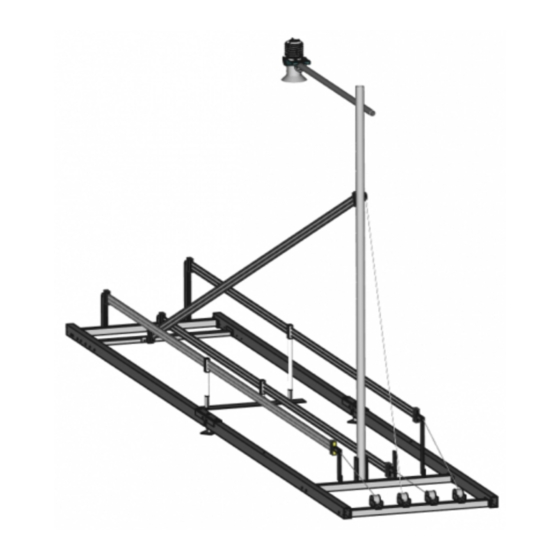
Page 23: Supporting Frame
Figure 6 Assembled SPA-frame Figure 7 Cross-profiles 7.3.2 Supporting frame Follow the steps below to assemble the supporting frame: Manual…
-
Page 24
The position of cross-profile nr. 8 has to match the mount- ing position of the tilted SPA-sensor on the mast (see alsoMast with tilted SPA-2-sensor and USH-9)! 4. Place the U-profiles Nr. 5 between the base-profiles nr.1 and 3, and nr. 2 and 4 using the hori- zontal bolts mounted to the profiles. -
Page 25
5. Adjust the bolts on each end of the U-profile so that they protrude 4 cm from the surface. You may need to lift the end of the base-profiles by a few cm to adjust the bolts. Tighten the lock-nuts. 6. -
Page 26: Mast With Tilted Spa-2-Sensor And Ush-9
7.3.3 Mast with tilted SPA-2-sensor and USH-9 Follow the steps below to set up the mast. It is recommended to attach all required items while the mast is lying on the ground. In this way no ladder or step is needed.
-
Page 27
1. Remove the bolts of the mast bracket on cross-profile nr. 11 and slide the bottom end of the mast into the bracket. 2. Turn the mast so that the protruding end of the attached bolt is facing to the right. Manual… -
Page 28
3. Fix the mast with the upper bolt of the mast bracket on cross-profile nr. 11. 4. Slide the bracket for the cross-arm approx. 30 cm over the top of the mast and tighten it loosely. 5. Slide the cross-arm into the bracket so that the short end protrudes max. 5 cm and tighten it. Make sure that the cross-arm is pointing perpendicular to the length of the supporting frame when it is standing upright! Now, tighten the 4 bolts of the bracket embracing the mast. -
Page 29
7. Plug the sensor cable to the USH-9 and fix it along the cross-arm and mast with cable ties. Coil up the excess sensor cable and attach it to the mast to avoid damage during the remaining installation steps. 8. Verify that the pulleys attached to the mast match the mounting position of cross-profile nr. 8. -
Page 30
12. Run the cable nr. 23 through the second pulley as shown below. 13. Fix cable nr. 23 with a cable tie to the mast as shown below. Make sure to run the cable around the pulleys exactly as shown in the figure. Only then the hoist to tighten the SPA rib- bon sensor will work properly. -
Page 31
16. Push up the mast into its upright position and fix it with the second bolt on cross-profile nr. 1 17. Secure the mast with the four guy cables to the base frame. The turnbuckles of cables nr. 21 (labelled 1) are mounted to the ring nuts on base-profile nr. 2 (left), and the buckles of cables nr. -
Page 32: Tilted Spa-Ribbon-Sensor
7.3.4 Tilted SPA-ribbon-sensor 1. Fasten the open end of the ribbon-sensor to the bracket on profile nr. 8. Make sure the rib- bon is not twisted and that the ring-nut can turn in the bracket-gap! 2. Hinge one of the tension springs nr. 20 into the clamp of pulley nr. 23. Manual…
-
Page 33
3. Hinge the loop of the cable fixed to the left winch on cross-profile nr. 7 into the other end of the tension spring as shown above. 4. Remove the temporary cable tie that held the hinge on the mast. 5. -
Page 34
bon are placed in the notches of the clips. 8. Secure the tilted SPA-ribbon by running the provided rope through the clips on the ribbon and the ring nuts on the supporting frame. Fasten the rope with a Fisherman’s knot, which allows repeated tightening. -
Page 35: Horizontal Spa-2-Ribbon-Sensor
7.3.5 Horizontal SPA-2-ribbon-sensor 1. Roll out the ribbon-sensor in such a way that the end with the sensor cable lies next to the mast. 2. Attach the near end of the ribbon-sensor to the sliding clamp on profile nr. 11. Make sure that the sensor cable is pointing upwards and that the ring-nut can turn in the clamp-gap! 3.
-
Page 36
4. Hook the tension spring nr. 20 into the other end of the sliding clamp on cross profile nr.11. 5. Hinge the loop of the cable fixed to the right winch on cross-profile nr. 7 into the other end of the tension spring. -
Page 37: Control Cabinet
placed in the notches of the clips. 10. Slide the plastic cylinders over the clips and place them in the positioning supports nr. 14 (see figure above). 7.3.6 Control cabinet 1. Mount the control cabinet to the mast with the provided U-bolts. The cabinet should be attached sideways below the tension spring of the tilted SPA-sensor.
-
Page 38: Wiring
1. Verify that the SPA and USH-9 sensor cables are fed through the base of the cabinet as illus- trated below. 2. Connect the SPA-sensor cables to the controller in the order shown above. The sensor wires are connected to the SPA-2 controller as illustrated below. Manual…
-
Page 39
Figure 8 Wiring of SPA-ribbon sensor Wire color Function Description not connected white/brown Receive Received signal green/yellow Transmit Transmitted signal shield cable shield Table 2: Connection wires of SPA-ribbon sensor 3. Connect the wires of the USH-9 as shown in Table 3 and the figure below. -
Page 40: Power Supply
7.3.8 Power supply The SPA-2 is designed for extreme environmental conditions at remote sites and with no grid con- nection. The sensor switches automatically into standby-mode between measurements and thus consumes only approx. 0.2 Ah per day (measurement duration 6 sec and measurement interval 60 sec) which can be supplied by a 12V-solar-generator mounted to the mast.
-
Page 41: Lightning Protection
Consult an expert for advice. The SPA-2 is protected against overvoltage. If a data logger is mounted to the mast, its ground lug must be properly connected to earth ground.
-
Page 42: Maintenance
8 Maintenance The SPA-2 generally does not require any special maintenance. However, we recommend to check the following: Sits the installation firmly on the ground? Is the mast in the upright position? Are the SPA-ribbon sensors damaged and tightly stretched? Are the clips in the upright pos-…
-
Page 43: Support Software Commander
9 Support software Commander What can I do with it? The Commander is a multipurpose software tool to configure and operate any Sommer Mess- technik device. It offers the following functions: Communication with Sommer Messtechnik sensors and data loggers via serial connection, modem, socket, IP-call and Bluetooth®…
-
Page 44
Read the instructions and click Next Select the installation type and click Next Manual… -
Page 45
Only for me No admin rights are required. Updates are only available to the user who installed the software. Installation folders: User program folder: UsersUserAppDataLocalProgramsSommerCommander Data structure: UsersUserAppDataLocalProgramsSommer Specific folder (default): C:SommerCommander Data structure (default):… -
Page 46
Standard program folder: Program Files (x86)SommerCommander Data structure: UsersPublicPublic documentsSommer Specific folder (default): C:SommerCommander Data structure (default): C:Sommer Select the installation directory and click Next. Select the features to be installed and click Next. Manual… -
Page 47
Click Install to start the installation. Click Finish to complete the installation. Manual… -
Page 48
Manual… -
Page 49
Configuration with a terminal program 10.1 Configuration with Commander support software Follow the steps below to modify the configuration parameters of the SPA-2: 1. Establish a connection between your PC and the SPA-2 as described in Connect the SPA-2 to Select the tab… -
Page 50
Save the parameter file to your PC by clicking Save parameter file. This step is recommended to track any configuration changes. Manual… -
Page 51
The Commander software ships with an integrated terminal program. However, communication with the SPA-2 can be performed with any terminal program. Follow the steps below to modify the configuration parameters of the SPA-2: 1. Establish a connection between your PC and the SPA-2. -
Page 52
NOTE As an unwanted switching into the menu mode has to be avoided the timing of the three question marks ??? is very restrictive and must never be finished with Return/Enter. This is especially import- ant for command line tools, which may automatically send a closing «Carriage return”. -
Page 53
10.3 Configuration errors 10.3.1 Device messages During configuration via RS-485 the SPA-2 may return the following messages. The device messages are bit-coded and returned in hex format. If multiple messages are present the message codes are summed up. Message code… -
Page 54
PLEASE NOTE: Sorry, job site! Table 5: Device messages 10.4 What do I need to configure? When first setting-up a SPA-2 at a measurement site, the parameters described below may need to be adapted. 10.4.1 General settings Language/Sprache The menu language. -
Page 55
The SPA-ribbon-sensors are calibrated by measuring the complex capacities in dry air (zero) and with an attached reference plate that simulates a certain water content (span). Sommer Mess- technik only ships calibrated SPA-ribbon sensors and generally, a regular zero-check of the sensors is sufficient. -
Page 56
1. Install the SPA-2 as described in Section How do I install the SPA-2?. 2. Connect the SPA-2 controller to your PC and a power-supply with the specified rating. 3. Open the Commandersoftware and establish a connection to the SPA-2 as described in do I start?. -
Page 57
After the adjustment, test the sensors again. 10.4.4 Span test and adjustment Follow the instructions below to perform a span-test for each SPA-2-ribbon sensor: 1. Mount the reference plate to the SPA-ribbon sensor as shown in Figure 9: loosen the knurled bolts and attach the plates to the ribbon. -
Page 58
Technics menu. 3. Click Test sensor. The SPA-2 performs a measurement and displays the results in a pup-up win- dow. The C-values at both frequencies should increase by 100 ±10 pF, i.e. reach 183 pF. The fraction of… -
Page 59
SDI-12 11.2 Which data do I get? The SPA-2 includes a RS-485 and a SDI-12 interface for communication and data output. The meas- urement values returned by one of these ports are arranged in a fixed sequence and are identified… -
Page 60
Index Variable Unit Description density S3 kg/m^3 Density of SPA-sensor 3 SWE S3 Snow water equivalent of SPA-sensor 3 ice content S4 Ice content of SPA-sensor 4 water content S4 Water content of SPA-sensor 4 density S4 kg/m^3 Density of SPA-sensor 4 SWE S4 Snow water equivalent of SPA-sensor 4 Analog 2… -
Page 61
RS-485 communication is primarily used to trigger measurements and read their results. It also per- mits to change parameters of the SPA-2. 11.3.3 How do I wire it? The SPA-2 can be connected to a data logger or a RS-485 network according to the figure below. https://www.lammertbies.nl/comm/info/RS-485.html Manual… -
Page 62
Wiring of the SPA-2 with a data logger via RS-485 11.3.4 How do I configure it? The SPA-2 has serial RS-485 communication enabled by default. If the device is integrated into a RS- 485 network or connected to a stand-alone data acquisition system, e.g. a data logger, the para-… -
Page 63
01 Output values Command se identifies automatically sent values Table 8: Header of the Sommer protocol Measurement value A measurement value (02 1539|) has a length of 8 digits and is returned together with its index. If the measurement value is a decimal number, one digit is reserved for the decimal char- acter. -
Page 64
4-digit hex number Hhhh End character Control characters Carriage return and Line feed <CR><LF> Table 10: End sequence of the Sommer protocol Example Sommer protocol Output values The acquired data are returned as in the following example: EXAMPLE #M0001G00se01 0.3|02 … -
Page 65
Water content of SPA-sensor 3 10 1.2| … Closing sequence 5E2A; Header with system key 00, device number 01 and string number 02 #M0001G02se Snow depth measured by SPA-2 17 480| Variable acquired by analog input 2 18 0.0735| … Closing sequence 944D;… -
Page 66
Parameter Format Description Identifier M_ Measurement values System key Device number Table 12: Header of the Standard protocol Measurement values Measurement values are returned in sequence and are separated by a blank. A measurement value has a length of 8 digits. If the measurement value is a decimal number, one digit is reserved for the decimal character. -
Page 67
M01_0001 Ice content of SPA-sensor 3 Water content of SPA-sensor 3 … Header with identifier for measurement values M02_0001 Snow depth measured by SPA-2 0.0735 Variable acquired by analog input 2 … Header with identifier for measurement values M03_0001 Capacity of SPA-sensor 3 at low frequency 92.3… -
Page 68
Description Start char- acter Identifier W SPA-2 returns a confirmation on receipt. This com- mand type demands a closing sequence with a valid CRC-16. S SPA-2 does not acknowledge the receipt of the command. This command type demands no closing sequence and therefore no CRC-16. -
Page 69
EXAMPLE Answer: none #S0001$pt| The data string is returned as soon as the SPA-2 has processed the command. Request a single measurement value The reading command R together with the index of the requested measurement returns a single measurement value. In the following example the measurement value with index 01 (in this… -
Page 70
11.4.2 What can I do with it? The SPA-2 listens to standard SDI-12 commands as listed in the SDI-12 specifications of version 1.3, e.g., to trigger a measurement or retrieve measurement results. Additionally, a set of extended SDI- 12 commands is implemented in all SOMMER sensors for instrument configuration. -
Page 71
11.4.4 How do I configure it? The SPA-2 has SDI-12 communication enabled by default. If the device is connected to a data acquis- ition system, e.g. data logger, and if multiple SDI-12 devices are connected to the same bus, the SDI-12 address may need to be adapted. -
Page 72
SDI-12 address SDI-12 version prior to the point SDI-12 version after the point Sommer Description of the company (6 characters and 2 blanks) Description of the firmware (5 characters and 2 blanks) 140r90 Firmware version (6 characters and 2 blanks) Device designation (max. -
Page 73
Configure device The configuration parameters of a SOMMER sensor are read with the command aXRpp! and writ- ten with the command aXWpp=vvv!, with a the sensor address, pp the parameter identifier and vvv the value of the parameter. -
Page 74
Read and write a parameters of a table Some SOMMER sensors are equipped with multiple transducers and their settings are listed in a table (see example below). A value within such a table is addressed by its row-index (01, 02 …) and column-index (A, B …). -
Page 75
11.5.2 What can I do with it? Modbus-communication with SPA-2 allows reading of measurement values and device information by a Modbus master. Additionally, the basic RS-485 port settings can be written to the SPA-2. 11.5.3 How do I wire it? For Modbus communication the SPA-2 is wired according to the table below. -
Page 76
Follow the instructions below to change the communication of a Sommer-device (in this example a RG-30) to Modbus: 1. Connect the USB to RS-485 converter to the data cable of the Sommer-device and a USB port on your PC. 2. Connect the sensor to a power supply with the specified rating. -
Page 77
NOTE Modbus cannot trigger measurements! Make sure to use the trigger option suitable for your application! Verify that the connection to the Sommer-device is active and click into the Terminal window. Type ??? to enter the sensor-menu. Manual… -
Page 78
Navigate to RS485 protocol and select MODBUS, set default… Please note, that the index-let- ters might be different for your Sommer-device! Manual… -
Page 79
Acknowledge the safety-note. After completion the following message will be displayed: Enter X until you get back to the main menu. The Sommer-device is now restarted and avail- able for Modbus-communication. As the connection-parameters have been changed to Mod- bus, the connection to the sensor is lost. Press Disconnect for completion. -
Page 80
1 stop Baud rate 19200 Flow control Transmitter warm-up time 10 ms Minimum response time 30 ms 11.5.5 How do I switch back to Sommer protocol? Follow the instructions below to change the data output back to Sommer-protocol: Manual… -
Page 81
Open the Connections (F8) tab and click connection. Enter the Name of the new connection. We recommend to use a meaningful name for later recognition, e.g. Modbus31 (19200) to indicate port 31 and Baud-rate 19200. Select the Type Serial connection and choose the Port your sensor is connected to, set the… -
Page 82
Click Save connection. In the Communication window select Mode Connection and choose the Connection have created. Then click Connect. Manual… -
Page 83
Save the parameter file for future use and to document con- figuration changes! Now, two options are available to revert communication back to the Sommer-protocol: If a parameter file is available that has the Sommer-protocol enabled, the file can be loaded by clicking Open parameter… -
Page 84
If no parameter file is available, the device has to be reset to its default configuration: Click into the Terminal window and type ??? to enter the sensor-menu. Manual… -
Page 85
Acknowledge the safety-note. Enter X until you get back to the main menu. The Sommer-sensor is now restarted and available in its initial configuration. As the connection-parameters have been changed to the default settings, the connection to the sensor is lost. Press Disconnect for completion. -
Page 86
Unit / Index Register address Variable Bytes Format value Test Hardcoded test value 2.7519… float value snow depth ice content S1 water content S1 density S1 kg/m^3 SWE S1 ice content S2 water content S2 density S2 kg/m^3 SWE S2 ice content S3 water content S3 density S3… -
Page 87
Unit / Index Register address Variable Bytes Format value 65533 Device type and con- 3701 figuration Device unsigned 65534 Software version XYYZZ info 65535 Modbus version 10100 Write single registers and read holding registers Some RS-485 port settings can be written to the registers of function 06 (write single registers) or read from the registers of function 03 (read holding registers): Register address Variable… -
Page 88
Report slave ID The Modbus function 17 (report slave ID, read only) can be used to read basic information of the SPA-2. The following example shows the response of function 17 of a RG-30 sensor, which is received in hex-format:… -
Page 89
«S» Run status (0=inactive; FF=active) Modbus implementation version 27 74 10100 Separator » » Vendor string 53 6F 6D 6D «Sommer » 65 72 20 response Separator » » Device configuration 52 47 2D 33 “RG-30 “ 30 20 20 Separator «… -
Page 90: A Measurement Trigger
Measurement is triggered by all options mentioned above. B Measurement Interval An internal measurement interval can be set for the SPA-2. If selected in menu item Measurement trigger, measurements are performed in the defined interval. However, a measurement is always completed before a new one is initiated.
-
Page 91: C Measurement Table
C Measurement table In the measurement table the recorded variables are selected. By default, the measurement table contains the following variables: Identifier Unit Dec. Scale Offset S-Typ S-Num S-MEA snow depth as S RECYC ice content S1 as S SPA-S water content S1 as S SPA-S…
-
Page 92
Identifier Unit Dec. Scale Offset S-Typ S-Num S-MEA Analog 3 as S AIN3 Analog 4 as S AIN4 C_LF S1 as S SPA-S C-LF C_HF S1 as S SPA-S C-HF C_LF S2 as S SPA-S C-LF C_HF S2 as S SPA-S C-HF C_LF S3… -
Page 93
The slope applied to the selected variable. Only available if Decimals is set to 1…5 or none. If Decim- is set as S (as source), no scaling is applied. Offset The offset applied to the selected variable. Adjustment (Correction) A measurement of the selected variable is triggered and the result displayed in the terminal win- dow. -
Page 94
S-MEA must be set to 2. SOMMER sensor that supports the SBP-protocol (via RS-485) The sensor address is set in S-NUM, and the position of the measurement value within the output string is assigned in S-MEA. SOMMER sensor that supports the MIO-protocol (via RS-485) The sensor address is set in S-NUM, and the position of the measurement value within the output string is assigned in S-MEA. -
Page 95: D Snow Depth Adjust
The number of the SPA-2 sensor variable or an internal system variable, the connection port of the selected analog sensor, or the position of the measurement value within the string returned by a connected SDI-12 sensor. See S-TYP for the available options.
-
Page 96
The character used as decimal separator in the values of the settings and in serial data strings. Option Description comma dot (default) Sleep mode Defines the behavior of the SPA-2 between two measurements, provided the measurement inter- val is longer than the time of the measurement itself. The following options are available: Manual… -
Page 97
ID, except if a SPA-2 device is replaced. In such a case it can be practical to change the ID of the new device to the ID of the replaced device to guarantee data consistency. -
Page 98
Sensor adjustment value. C base HF Sensor adjustment value. Sensor zero adjust Function to perform a zero adjustment of the sensor (see Section Calibration of SPA-2-ribbon- sensors for details). Test sensor Function to perform a test measurement of the selected SPA-sensor. -
Page 99
Value Range 0…9, a…z, A…Z 0 (default) F-G-B SDI12 ‘M’-response Defines how an SDI-12 M-command received by the SPA-2 is answered if the requested number of measurement values exceeds 9. The following options are available: Parameter Description expand address This option should only be used with SDI-12 standard V1.0. -
Page 100
F-G-C SDI-2 maximal duration The timeout for commands sent to SDI-12 devices connected to the SPA-2. If a SDI-12 device does not respond to a command within this time the device returns an error. Unit Seconds Value range 0 … 255… -
Page 101
F-H-A Baud rate The following transmission rates in bps (baud) can be selected: 1ˈ200 2ˈ400 4ˈ800 9ˈ600 (default) 19ˈ200 38ˈ400 57ˈ600 115ˈ200 F-H-B Parity, stop bits The following combinations of parity and stop bits can be selected: Option Description no par, 1 stop (default) No parity and 1 stop bit no par, 2 stop No parity and 2 stop bits… -
Page 102
Unit Milliseconds Value range 0…2ˈ000 10 (default) F-H-E Flow control The XOFF-XON flow control can be activated with this setting. Option Description Off (default) no flow control XOFF-XON blocking XOFF-XON flow control, especially adapted for half-duplex systems F-H-F Sending window If XON-XOFF flow control is activated data are transmitted in blocks with the defined length. -
Page 103
F-H-I Trig, timeout The time the SPA-2 is waiting until expected commands/answers are received via the RS485-2 inter- face. Unit Seconds Value range 3 … 250 60 (default) F-H-J Trig, sleep while timeout To reduce power consumption the SPA-2 can switch to a sleep mode between measurements. -
Page 104
With this mode the settings of a connected digital sensor can be read or changed. RS-485-1 Protocol The RS-485-1 interface is used to read acquired data and to configure the SPA-2. The following para- meters are available to configure the protocol; the port settings are defined in RS-485-1 Port. -
Page 105: F-I-C Output Protocol (Op)
The type of the serial output protocol. The following options are available: Option Description Sommer (default) Sommer protocol; data values are returned with an index starting at 1 Standard Standard protocol; data values are returned without an index MODBUS Modbus protocol…
-
Page 106: F-I-Fop, Wake-Up Sequence
Serial data can be transmitted to a recording device automatically without a request. However, many devices demand a wake-up sequence before they can receive and process data. The SPA-2 has the option to send a sync sequence and a prefix before data are transmitted (see…
-
Page 107
RS-485-1 Port F-J-A Baud rate F-J-B Parity, stop bits F-J-C Minimum response time F-J-D Transmitter warm-up time F-J-E Flow control F-J-F Sending window F-J-G Receiving window F-J-A Baud rate The following transmission rates in bps (baud) can be selected: 1ˈ200 2ˈ400 4ˈ800 9ˈ600 (default) -
Page 108: Value Range 0
F-J-C Minimum response time Setting of this parameter avoids interference of communication at the RS-485 interface. For this pur- pose the response to a command is delayed by the selected time. Additionally, the response is kept compact. Unit Milliseconds Value range 0…2ˈ000 10 (default) F-J-D…
-
Page 109: G Special Functions
G-A Device status Displays information about the sensor and the software version. G-B View setup All parameters of the SPA-2 are listed in the terminal window. G-C Set factory default All parameters are reset to factory defaults. Only available in terminal-mode.
-
Page 110
Glossary Modbus A serial communications protocol for connecting industrial elec- tronic devices. RS-485 A standard defining the signal transmission serial com- munication systems. SDI-12 Asynchronous serial com- munications protocol for intel- ligent sensors (Serial Digital Interface at 1200 baud) Manual… -
Page 111
Index Modbus 55, 75-76, 87, 105-106 RS-485 14, 17, 40, 53, 55, 59, 61-62, 68, 75- 76, 87, 90, 94, 97, 100-101, 104-105, 107-108 SDI-12 14, 17, 40, 55, 59, 70-71, 77, 90, 94, 99-100, 105 Manual…
ТЕХНИЧЕСКОЕ ОБСЛУЖИВАНИЕ И ТЕКУЩИЙ РЕМОНТ
-
Общие положения
3.1.1 Для обеспечения надежности работы МСУД-Н как и всего остального электронного оборудования электровоза, устанавливаются виды и периодичность планово-предупредительного обслуживания и ремонта указанные в таблице 3.1.
Таблица 3.1 – Периодичность планово-предупредительных ремонтов МСУД-Н
| Виды обслуживания и ремонта | Межремонтный пробег |
| Техническое обслуживание (ТО), не более, ч | 96 |
| Текущий ремонт (ТР), тыс. км. | от 45 до 55 |
| Средний ремонт (СР), тыс. км. | от 540 до 660 |
| Капитальный ремонт (КР), тыс. км. | от 2160 до 2640 |
3.1.2 К обслуживанию аппаратуры управления, наладочным и регулировочным работам в ней допускаются только специально обученные лица, знающие схемы блока управления
БУ-193-02, имеющие практические навыки работы с измерительными приборами, прошедшие проверку знаний по ПТЭ и ПТБ при работе с электроустановками и имеющие квалификационную группу не ниже V. Проведение наладки и регулировки локомотивными бригадами — недопустимо.
3.1.3 Наладочные и профилактические работы, которые осуществляются при включенном питании, должны осуществляться не менее чем двумя лицами из обслуживающего персонала.
3.1.4 Наличие пломб, предусмотренных технической документацией разработчика на дверце БУ-193-02 и крышках блоков БИ обязательно.
ВНИМАНИЕ! Эксплуатация не опломбированной аппаратуры запрещается.
3.1.5 Перечень лиц, имеющих право снимать и устанавливать пломбы, устанавливается письменным распоряжением начальника локомотивного депо.
-
Контрольно-измерительные приборы и тестовое оборудование
3.2.1 Мегомметр М4100/3 ТУ25-04.2131-78 для проверки сопротивления изоляции при капитальном ремонте КР.
3.2.2 Персональный IBM совместимый компьютер типа NOTEBOOK.
Персональный компьютер необходим для:
- занесения в памяти блока управления и блока индикации технологического программного обеспечения в соответствии с методиками, приведенными в приложениях Б, В настоящего РЭ;
— функциональной диагностики системы при ремонте в условиях депо и производства.
3.2.3 Стенд СПА-002
Стенд СПА-002 АРКИ.421455.002 совместно с персональным компьютером используется для проверки системы после изготовления и при обслуживании в условиях депо.
Стенд СПА-002 выполняет следующие функции:
— вырабатывает все необходимые для работы системы напряжения;
— имитирует сигналы, поступающие цепей управления, задатчиков и датчиков электровоза;
— обеспечивает индикацию всех имитируемых сигналов;
— обеспечивает индикацию всех выдаваемых проверяемой системой сигналов;
— обеспечивает проверку съемных блоков, входящих в состав системы.
Стенд СПА-002 питается от сети переменного напряжения 220 В 50 Гц и подключается к системе с помощью входящих в его комплект кабелей.
Порядок работы со стендом СПА-002 описан в Руководстве по эксплуатации на стенд СПА-002 АРКИ.421455.002 РЭ.
-
Указание мер безопасности
3.3.1 Сборку схемы, ремонт и подключение съемных блоков, входящих в состав
БУ-193-02, подключение и отключение измерительных приборов необходимо производить при опущенном токоприемнике, выключенном главном выключателе и отключенных источниках питания цепей управления.
3.3.2 Работы по проверке и наладке БУ-193-02 производить с резинового коврика. Все приборы, используемые для проверки блока, необходимо располагать на резиновых подставках или ковриках.
3.3.3 При проведении ремонтных работ пайка должна производиться паяльником, имеющим напряжение питания не более 36 В.
3.3.4 Наладку системы управления на электровозе, находящемся под контактным проводом, производить при полностью укомплектованных средствах пожаротушения.
Для ознакомления с инструкцией необходимо нажать на ссылку «ЗАГРУЗИТЬ», чтобы скачать pdf файл. Если есть кнопка «ПРОСМОТР», то можно просто посмотреть документ онлайн.
Для удобства, Вы можете сохранить данную страницу с файлом руководства по эксплуатации в свой список «избранное» прямо на сайте (доступно для зарегистрированных пользователей).
Смотрите инструкцию для похожих моделей:
- Похожих файлов не найдено.

Вы можете задать вопрос посетителям сайта по модели QSC SPA2-200. Если Вы являетесь её пользователем, то пожалуйста оставьте, по возможности развёрнутый отзыв:
инструкцияQSC SPA2-60

System Power Amplifier (SPA)
Руководство по установке
SPA2-60 Усилитель SPA4-60 УсилительSPA2-200 Усилитель SPA4-100 Усилитель
ЗНАЧЕНИЕ СИМВОЛОВ
Термин «ПРЕДУПРЕЖДЕНИЕ!» указывает на наличие инструкций, касающихся личной безопасности. Невыполнение этих инструкций может привести к травме или смерти.
Термин «ВНИМАНИЕ!» указывает на наличие инструкций, связанных с возможным повреждением оборудования. Невыполнение этих инструкций может привести
к повреждению оборудования, не подлежащему гарантийному обслуживанию.
Термин «ВАЖНО!» указывает на наличие инструкций или информации, которые являются важными для выполнения описываемой процедуры.
Термин «ПРИМЕЧАНИЕ» используется для указания дополнительной полезной информации.
Значок мигающей лампочки с символом в виде указателя стрелки в треугольнике предупреждает пользователя о наличии опасных неизолированных
контактов внутри корпуса прибора, напряжение на которых может оказаться достаточным для создания риска поражения электрическим током у людей.
Восклицательный знак в равностороннем треугольнике предупреждает пользователя о наличии в этом руководстве важных инструкций по безопасности
и эксплуатации.
Содержимое упаковки
1шт.
SPA2-60
SPA2-200
SPA4-60
SPA4-100
1шт.
Шнур питания
переменного
тока, стандарт
США
2шт.
Кронштейн
для крепления
кстойке
№ дет. QSC
CH-001344-00
2шт.
Соединительная
накладка
№ дет. QSC
CH-001345-00
2шт.
Прокладка кронштейна
длякрепления к стойке
№ дет. QSC
CH-001386-00
6шт.
Винт
сцилиндрической
головкой
M4x7мм
6шт.
Винт с плоской
головкой
M3x6мм
4шт.
Резиновая прокладка
№ дет. QSC
PL-001023-00
1шт.
Крышка-этикетка
кронштейна для
крепления к стойке
№ дет. QSC
LB-001138-00
SPA 2канала 1 шт.
SPA 4канала2 шт.
Евро-разъем 3,5 мм,
4 конт., зел.
№ дет. QSC
CO-000646-00
SPA 2канала 1шт.
Евро-разъем 3,5 мм,
5 конт., зел.
№ дет. QSC
CH-000644-00
SPA 2канала 1шт.
Евро-разъем 3,5 мм,
4 конт., черн.
№ дет. QSC
CO-000645-00
SPA 4канала1шт.
Евро-разъем 3,5 мм,
10 конт., зел.
№ дет. QSC
CO-000647-00
SPA 4канала1шт.
Евро-разъем 3,5 мм,
10 конт., зел.
№ дет. QSC
CO-000648-00
1шт.
Гарантия
TD-000453
1шт.
Информация
по технике
безопасности
TD-000337
TD-000500 -06 -D *TD-000500-06*
Посмотреть инструкция для QSC SPA2-60 бесплатно. Руководство относится к категории приемники, 1 человек(а) дали ему среднюю оценку 7.5. Руководство доступно на следующих языках: русский. У вас есть вопрос о QSC SPA2-60 или вам нужна помощь? Задайте свой вопрос здесь
Главная
| QSC | |
| SPA2-60 | QSC 7287 | |
| приемник | |
| 0684284066985 | |
| русский | |
| Руководство пользователя (PDF), Инструкция по установке (PDF), Техническая спецификация (PDF) |
Аудио
| Пиковая мощность на канал | 60 W |
| Выходная мощность RMS на канал (4 Ом) | 60 W |
| Выходная мощность RMS на канал (8 Ом) | 60 W |
| Выходная мощность на канал в режиме «мост» (4 Ом) | 200 W |
| Выходная мощность на канал в режиме «мост» (8 Ом) | 200 W |
| Выходные звуковые каналы | 4.0 канала |
| Класс усилителя | D |
| Суммарный коэффициент гармоник (THD) | — % |
| Сoотношение «сигнал/помеха» (SNR) | 100 dB |
| Полное сопротивление на входе | 10 Ω |
| Входная чувствительность | 1.23 mV |
| Диапазон частот | 20 — 20000 Hz |
Технические характеристики
| Поставляемые кабели | Кабель переменного тока |
| Краткая инструкция пользователя | Да |
| Входное напряжение источника питания | 12.3 V |
| Емкость стойки | 1U |
| Предназначение | — |
| Технология подключения | Проводная |
| Цвет товара | Черный |
| Регулировка усиления | Цифровой |
| Вкл/Выкл переключатель | Да |
Порты и интерфейсы
| Тип подключения колонок | 3,5 мм |
Вес и размеры
| Ширина | 220 mm |
| Глубина | 241 mm |
| Высота | 43 mm |
| Вес | 1600 g |
Индикация
| Светодиодные индикаторы | Да |
Сертификаты
| Сертификация | UL, CE, ENERGY STAR, RoHS/WEEE compliant, FCC Class B (Conducted and Radiated emissions), UL 2043 witd PL-Kit |
Данные об упаковке
показать больше
Не можете найти ответ на свой вопрос в руководстве? Вы можете найти ответ на свой вопрос ниже, в разделе часто задаваемых вопросов о QSC SPA2-60.
Не нашли свой вопрос? Задайте свой вопрос здесь