- Manuals
- Brands
- SSANGYONG Manuals
- Automobile
- Korando 2010
Manuals and User Guides for SSANGYONG Korando 2010. We have 1 SSANGYONG Korando 2010 manual available for free PDF download: Manual

- Manuals
- Brands
- SSANGYONG Manuals
- Automobile
- Korando 2010
- Manual
-
Contents
-
Table of Contents
-
Bookmarks
Related Manuals for SSANGYONG Korando 2010
Summary of Contents for SSANGYONG Korando 2010
-
Page 1: Table Of Contents
GENERAL INFORMATION 0000-00 GENERAL INFORMATION GENERAL INFORMATION 1. MAJOR DIMENSION……2. VEHICLE IDENTIFICATION….3. EXTERIOR LAMP SYSTEM LAYOUT..4. INTERIOR LAMP SYSTEM LAYOUT..5. SWITCH SYSTEM LAYOUT….6. CAN COMMUNICATION CONFIGURATION……..ELECTRIC DEVICE GENERAL INFORMATION 1. HOW TO READ ELECTRICAL WIRING DIAGRAM……….
-
Page 2: General Information
01-2 0000-00 GENERAL INFORMATION 1. MAJOR DIMENSION 2. VEHICLE IDENTIFICATION Top View 1) The engine number (671 950 0 2 2) The chassis number 5000001) is stamped on the lower area of (KPTA0B1SSAP012345) is stamped on the cylinder block in exhaust manifold side. right side in the engine compartment (passenger side).
-
Page 3: Exterior Lamp System Layout
01-3 0000-00 3. EXTERIOR LAMP SYSTEM LAYOUT Front view Rear view High-mounted stop lamp Side repeater lamp Tail/stop lamp Puddle lamp Backup lamp Front turn signal lamp Rear turn signal lamp Position lamp Tail lamp Headlamp assembly Reflector Front fog lamp License plate lamp GENERAL INFORMATION undefined…
-
Page 4
01-4 0000-00 Headlamp Rear combination lamp Stop lamp and tail lamp Turn signal lamp Backup lamp Stop lamp (For Korea) Rear fog lamp High-beam/low-beam Turn signal lamp Position lamp Front fog lamp License plate lamp High mounted stop lamp Puddle (approach) lamp Side repeater lamp Vehicle with spoiler Vehicle without… -
Page 5: Interior Lamp System Layout
01-5 0000-00 4. INTERIOR LAMP SYSTEM LAYOUT Glove box lamp Center room lamp Luggage lamp Front room lamp Sun visor lamp Door courtesy lamp GENERAL INFORMATION undefined…
-
Page 6: Switch System Layout
01-6 0000-00 5. SWITCH SYSTEM LAYOUT Steering wheel remote Overhead console Passenger door Front seat heated wire Front seat heated wire Rear door switch (RH) control switch switch switch switch (DLX) switch (STD) Center room lamp switch Cruise control switch Luggage lamp switch Multifunction switch Lower main panel…
-
Page 7: Can Communication Configuration
01-7 0000-00 6. CAN COMMUNICATION CONFIGURATION 2) CAN Communication Wiring Diagram There are two types (P-CAN and B-CAN) of communication according to the communication speed. The instrument cluster and BCM (Body Control Module) communicate through both P- CAN and B-CAN at the same time. 1) CAN Configurations (P-CAN/B-CAN) Abbreviations Meaning…
-
Page 8: Electric Device General Information
01-8 0000-00 ELECTRIC DEVICE GENERAL INFORMATION 1. HOW TO READ ELECTRICAL WIRING DIAGRAM (1) HOW TO READ ELECTRICAL WIRING DIAGRAM GENERAL INFORMATION undefined…
-
Page 9
01-9 0000-00 (2) CONTENTS OF ELECTRICAL WIRING DIAGRAM(CIRCUIT) (4) FUNCTION OF POWER SUPPLY LINE(NUMBER) Position Emplanation Power supply NO. Power supply condition » » » » A top of horizontal line means Power supply and it is separated depending on Battery Voltage (B+) Supply in Ignition Switch ON and ST (IGN 1) -
Page 10: How To Check Terminal Number Of Connector
01-10 0000-00 (6) ELECTRIC SYMBOLS 2. HOW TO CHECK TERMINAL NUMBER OF CONNECTOR ▶ Terminal number is given based on Female Terminal Male Connector ex) Terminal Number 4 of C901 connection ▶ Terminal number of Connector Generally, the Connector terminal number is given from left to right direction of Locking upper position through the Female Terminal.
-
Page 11: Part Location According To Connector Number
01-11 0000-00 3. PART LOCATION ACCORDING TO CONNECTOR NUMBER ▶ C : Symbol Character for Connector ex) C102 Symbol Character Description Connector (Connecting part that connects two wiring harness) Diode Ground Splice pack (Joint connector that connects various wiring harness) ▶…
-
Page 12
CONNECTOR/GROUND 1413-02/8210-00/8210-01/8211-01/8212-01/8212-02 /8213-03/8213-04/8213-06/8213-09/8213-108810-22/8810-23 CONNECTOR/GROUND WIRING HARNESS 8210-00 WIRING HARNESS, COMPONENTS LOCATION..8210-00 CONNECTOR, GROUND / SPLICE PACK……CONNECTOR/GROUND 8210-01 W/H MAIN……..8212-01 W/H FLOOR(LH)……8212-02 W/H FLOOR(RH)……1413-02 W/H ENGINE MAIN….. 8211-01 W/H ENGINE EXTN….. 8213-09 W/H ROOF……… 8810-22 W/H AIR BAG……8810-23 W/H AIR BAG EXTN…. -
Page 13: Wiring Harness
02-2 8210-00 WIRING HARNESS WIRING HARNESS, COMPONENTS LOCATION 8210-00 (1) WIRING HARNESS CONNECTOR/GROUND undefined…
-
Page 14
02-3 8210-00 (2) COMPONENTS LOCATION CONNECTOR/GROUND undefined… -
Page 15: Connector, Ground / Splice Pack
02-4 8210-00 CONNECTOR, GROUND / SPLICE PACK ▶ GROUND 8210-00 (1) CONNECTOR, GROUND, SPLICE PACK ▶ CONNECTOR ▶ SPLICE PACK CONNECTOR/GROUND undefined…
-
Page 16
02-5 8210-00 (2) SPLICE PACK CIRCUIT 1) S101 (HS-CAN) 4) S202 (HS-CAN) 2) S102 (HS-CAN) 5) S203 (ILL+) 3) S201 (LS-CAN) CONNECTOR/GROUND undefined… -
Page 17
02-6 8210-00 6) S204 (GND) S301 7) S205 (HS-CAN) CONNECTOR/GROUND undefined…
 -
Page 18
02-7 8210-00 (3) WIRING CONNECTOR PARTS SHAPE / NUMBERING CONNECTOR/GROUND undefined… -
Page 19
02-8 8210-00 (4) THE OTHERS PARTS SHAPE / NUMBERING ▶ UNIT PART ▶ SWITCH PART CONNECTOR/GROUND undefined… -
Page 20
02-9 8210-00 ▶ MOTOR PART ▶ SENSOR PART LAMP PART ▶ CONNECTOR/GROUND undefined… -
Page 21
02-10 8210-00 ▶ THE OTHER PART CONNECTOR/GROUND undefined… -
Page 22: Connector/Ground
02-11 8210-01 CONNECTOR/GROUND W/H MAIN 8210-01 CONNECTOR/GROUND undefined…
-
Page 23
02-12 8210-01 CONNECTOR/GROUND undefined… -
Page 24: W/H Floor(Lh)
02-13 8212-01 W/H FLOOR(LH) 8212-01 CONNECTOR/GROUND undefined…
-
Page 25
02-14 8212-01 CONNECTOR/GROUND undefined… -
Page 26: W/H Floor(Rh)
02-15 8212-02 W/H FLOOR(RH) 8212-02 CONNECTOR/GROUND undefined…
-
Page 27: W/H Engine Main
02-16 1413-02 W/H ENGINE MAIN 1413-02 ▶ TOP VIEW ▶ FRONT VIEW CONNECTOR/GROUND undefined…
-
Page 28: W/H Engine Extn
02-17 8211-01 W/H ENGINE EXTN 8211-01 CONNECTOR/GROUND undefined…
-
Page 29: W/H Roof
02-18 8213-09 W/H ROOF 8213-09 CONNECTOR/GROUND undefined…
-
Page 30: W/H Air Bag
02-19 8810-22 W/H AIR BAG W/H AIR BAG EXTN 8810-22 8810-23 CONNECTOR/GROUND undefined…
-
Page 31: W/H Driver Door
02-20 8213-03 W/H DRIVER DOOR W/H PASSENGER DOOR 8213-03 8213-04 CONNECTOR/GROUND undefined…
-
Page 32: W/H Rear Door
02-21 8213-06 W/H REAR DOOR W/H TAIL GATE 8213-06 8213-10 CONNECTOR/GROUND undefined…
-
Page 33
POWER DISTRIBUTION 8210-00/8410-04/8410-05 POWER DISTRIBUTION FUSE 8210-00 ENGINE ROOM FUSE / RELAY BOX……… 8410-04 INDOOR FUSE BOX….. 8410-05 ICM RELAY BOX…… -
Page 34
(1) ENGINE ROOM FUSE / RELAY BOX -TOP VIEW (3) ENGINE ROOM FUSE / RELAY BOX LOCATION (2) ENG ROOM FUSE / RELAY BOX -UNDER VIEW (4) BATTERY FUSE BOX LOCATION… -
Page 35
(5) USAGE OF FUSE IN ENGINE ROOM FUSE BOX (6) ENGINE ROOM FUSE BOX CONNECTOR NUMBER… -
Page 36
(7) ENGINE ROOM FUSE / RELAY BOX CIRCUIT ▶ SB1~SB6, SB10, Ef18~Ef19, START RELAY, BLOWER RELAY, DEFOGGER RELAY, DEICER RELAY… -
Page 37
▶ SB7~SB9, Ef1, Ef5, Ef9, Ef11, PTC RELAY, FUEL HEATER RELAY, HEAD LAMP RELAY(HI, LO) -
Page 38
▶ SB11~SB14, Ef12~Ef13, Ef24, ENG MAIN RELAY, C/FAN RELAY, C/FAN RELAY(HI, LO), COMP RELAY… -
Page 39
▶ Ef2~Ef4, Ef6~Ef8, Ef10, Ef14~Ef16, TAIL LAMP RELAY, FRT FOG LAMP RELAY… -
Page 40
▶ Ef17, Ef20~Ef23, Ef25~Ef26, WIPER MOTOR RELAY(HI, LO), HORN RELAY, POWER WINDOW RELAY… -
Page 41
(1) INDOOR FUSE BOX (2) POWER SUPPLY… -
Page 42
(3) INDOOR FUSE BOX CIRCUIT ▶ F27~F34… -
Page 43
▶ F35~F41… -
Page 44
▶ F42~F50… -
Page 45
▶ F51~F53… -
Page 46
▶ RR FOG LAMP RELAY, POWER OUTLET RELAY, BURGLAR HORN RELAY, RR WIPER RELAY, SHIFT LOCK RELAY… -
Page 47
▶ T/GATE OPEN RELAY, FOLDING MIRROR RELAY, IGN 1 RELAY, ACC RELAY, IGN 2 RELAY… -
Page 48
CIRCUIT 1461-01/1491-01/2112-02/2820-01/3110-17/3110-01/4610-04/4810-08/4892-01/6810-20/6810-15/7340-03/7410-02/7632-16/7770-02 /7810-01/7840-01/8010-01/8210-03/8210-01/8210-01/8310-10/8310-01/8310-01/8320-01/8510-52/8510-48/8510-05/8610-06/8620-01 /8710-03/8712-03/8790-01/8810-01/8930-40/8930-03/8930-01 CIRCUIT ENGINE 1461-01 STARTING / CHARGING….. 8610-06 HORN……….. 2820-01 GLOW CONTROL UNIT….7632-16 CIGAR LIGHTER / POWER 1491-01 ECU(D20DTF EU-V)…… OUTLET……..6810-15 PTC HEATER……. 7840-01 DEFOGGER / DEICER….8210-01 DIAGNOSIS CONNECTOR… 8710-03 DOOR LOCK CIRCUIT….7340-03 SUN ROOF……..8310-01 HEAD LAMP……… -
Page 51
(1) ENG MAIN RELAY, PEDAL MODULE, VALVE(THROTTLE, INLET METERING, EGR), SENSOR(HFM, O2, COOLANT TEMP, FUEL TEMP) -
Page 52
(2) STOP LAMP, W/SPEED SENSOR, T/PRESSURE SW, INJECTOR, SENSOR(FUEL FILTER, R/PRESSURE, CAM POSITION, MAP, KNOCK, E/GAS TEMP) -
Page 63
(1) POWER/GROUND, B/HORN, BUZZER, CLUSTER, HAZARD, ROOM LAMP, M/FUNCTION SW, IMMO, A/LIGHT… -
Page 64
(2) DR LOCK, FOLDING, DEFOG/DEICER, P/WINDOW, WIPER/WASHER, DR SWITCH… -
Page 90
VEHICLE GENERAL 0000-00 VEHICLE GENERAL SPECIFICATIONS AND CHECK ITEMS 1. VEHICLE IDENTIFICATION….2. SPECIFICATION……..3. OIL SPECIFICATIONS AND CAPACITY. -
Page 92
5000001) is stamped on the lower area of (KPTA0B1SSAP012345) is stamped on the cylinder block in exhaust manifold side. right side in the engine compartment (passenger side). 3) The certification label is affixed on the bottom of driver side B-pillar. (30 psi) VEHICLE GENERAL korando 2010.10… -
Page 93
01-4 0000-00 ▶ VIN number ▶ Engine number VEHICLE GENERAL korando 2010.10… -
Page 94
750 ± 20 rpm ← Water-cooled / forced Cooling system ← circulation Coolant capacity (ℓ) ← Gear pump, forced Lubrication type ← circulation Max. oil capacity (ℓ) ← (when shipping) Turbocharger and cooling type Turbocharger, water- ← cooled VEHICLE GENERAL korando 2010.10… -
Page 95
On demand type Clutch (M/T) Operating type Hydraulic type ← Disc type Dry single diaphragm ← type Power Type Rack and pinion (EPS, ← Steering HPS) Steering angle Inner 39.0° ← Outer 31.24° ← * ( ) Optional VEHICLE GENERAL korando 2010.10… -
Page 96
R-134a (430 ± 30g) ← Conditioner Electrical Battery type / Capacity MF / 12 — 90 ← (V-AH) Starter capacity (V-KW) 12 — 2.3 ← Alternator capacity (V-A) 12V — 140A (EPS), ← 120A (HPS) * ( ) Optional VEHICLE GENERAL korando 2010.10… -
Page 97
Ssangyong genuine oil (SAE 80W/90, ≒ 0.7 ℓ API GL-5) Brake / Clutch Fluid As required Ssangyong genuine oil (DOT4) Power Steering Fluid Ssangyong genuine oil (ATF DEXRON II) ≒ 1.0 ℓ * TOTAL FLUIDE DA (Extreme cold condition only) VEHICLE GENERAL korando 2010.10… -
Page 98
D20DTF ENGINE INFORMATION 0000-00 ENGINE GENERAL INFORMATION GENERAL INFORMATION 1. ENGINE LAYOUT……..2. MAJOR COMPONENTS……DURING SERVICE WORK 1. GUIDELINES FOR SERVICE WORK SAFETY……….2. JACK-UP POINTS……..3. STANDARD BOLTS SPECIFICATIONS.. SPECIAL TOOL 1. NEW SPECIAL TOOLS……2. NORMAL EQUIPMENTS…… -
Page 100: Engine Layout
01-3 0000-00 1. ENGINE LAYOUT Front view Rear view Right view Left view D20DTF ENGINE INFORMATION korando 2010.10…
-
Page 101: Major Components
Idler bearing 1 A/C compressor pulley Auto tensioner Idler bearing 2 Isolation damper ▶ Rear view E-EGR valve Fuel temperature sensor E-VGT actuator Fuel HP pump assembly Coolant temperature sensor Magnetic triggering Crankshaft position sensor D20DTF ENGINE INFORMATION korando 2010.10…
-
Page 102
▶ Left view Thermostat assembly Knock sensor 1 connector Oil cooler assembly Variable swirl valve assembly E-EGR valve Knock sensor 2 connector E-EGR solenoid valve EGR cooler Electronic throttle body T-MAP sensor Oil level switch D20DTF ENGINE INFORMATION korando 2010.10… -
Page 103: Guidelines For Service Work Safety
Major dedicated equipment: Engine and transmission jack (use the one for Chairman W), Engine stand, Engine crane, transmission jack, Engine hanger Engine crane Engine stand Transmission jack D20DTF ENGINE INFORMATION korando 2010.10…
-
Page 104
Coat oil or grease on the driving and sliding surfaces before installing parts. Use sealer or gasket to prevent leakage if necessary. (14) Tighten every bolt and nut with specified torque. (15) When service work is completed, check finally whether the work is performed properly or the problem is solved. D20DTF ENGINE INFORMATION korando 2010.10… -
Page 105
Replace the seals if necessary. (6) Engine oil Check the oil level and add oil if necessary. The best time to check the engine oil level is when the oil is warm. D20DTF ENGINE INFORMATION korando 2010.10… -
Page 106
0000-00 (7) Coolant Check the coolant level in the coolant reservoir and coolant condition (contamination, foreign material), coolant hose damage or leakage. Replace or add Ssangyong genuine coolant, if needed. (8) Engine drive belt Check all drive belts of the engine for wear, crack, looseness, tension. Retighten or replace the belt, if needed. -
Page 107
The HP fuel supply pipe (HP pump to fuel rail) and HP fuel pipe (Fuel rail to injector) should be replaced with new ones when removed. D20DTF ENGINE INFORMATION korando 2010.10… -
Page 108: Jack-Up Points
Stand jack-up points and installation status (front side) Stand jack-up points and installation status (front side) Mounting status Jack-up points Jack-up points for 2-post lift for 2-post lift Stand jack-up points and installation status (rear side) Mounting status D20DTF ENGINE INFORMATION korando 2010.10…
-
Page 109: Standard Bolts Specifications
Determine extra proper tightening torque if tightens with washer or packing. If tightens bolts on the below materials, be sure to determine the proper torque. Aluminum alloy: Tighten to 80 % of above torque table. Plastics: Tighten to 20 % of above torque table. D20DTF ENGINE INFORMATION korando 2010.10…
-
Page 110: New Special Tools
Used to release tension without removing belt when replacing pulley or pump. Use (Engine) Part number: T99110010A Name: Flywheel fixing device Use: Used to fix flywheel or drive shaft to prevent engine from rotating when removing crankshaft pulley. D20DTF ENGINE INFORMATION korando 2010.10…
-
Page 111: Normal Equipments
(transaxle) and can support at least 1 tone. Name: Engine crane (1 tone or more) Use: Used to move engine module (including transaxle) to working space or engine stand, and can support at least 1 tonne. D20DTF ENGINE INFORMATION korando 2010.10…
-
Page 112
Name: Oil pan gasket remover Use: Used to separate oil pan and minimize damage when removing oil pan. Name: Torque angle gauge Use: Used to angle-tighten correctly after torque- tightening Name: Fuel sender cover remover/installer D20DTF ENGINE INFORMATION korando 2010.10… -
Page 114
0.20 to 0.35 mm 2nd ring end gap 0.35 to 0.50 mm 3rd ring end gap 0.2 to 0.40 mm Offset 0.3 mm Head gasket Piston protrusion 0.475~0.540 1.2t 0.541 to 0.649 1.3t 0.650 to 0.745 1.4t ENGINE ASSEMBLY korando 2010.10… -
Page 115
30 ± 3 Nm Screw bolt 25 ± 2.5 Nm Coolant temperature 20 ± 2.0 Nm sensor Auto tensioner M7×45 (Low) 25 ± 2.5 Nm M12×90 (Up) 55 ± 5.5 Nm Coolant pump M6×50 10 ± 1.0 Nm ENGINE ASSEMBLY korando 2010.10… -
Page 116
25 ± 2.5 Nm (EGR cooler side) EGR combination bolt M6×16 10 ± 1 Nm M8×16 25 ± 2.5 Nm Tensioner pulley 45 ± 4.5 Nm Glow plug 20 ± 2 Nm Vacuum pump M8×25 25 ± 2.5 Nm ENGINE ASSEMBLY korando 2010.10… -
Page 117
(between fuel rail and injector ) Crank position sensor M5×14 8 ± 0.4 Nm Main wiring M6×16 10 ± 1 Nm Intake duct bracket M8×16 25 ± 2.5 Nm Power steering pump M8×100 25 ± 2.5 Nm ENGINE ASSEMBLY korando 2010.10… -
Page 118
Do not allow anybody to be in front of the vehicle. Warm the engine up to normal operating temperature (80°C). Disconnect the fuel rail pressure sensor connector to cut off the fuel injection. Place the diagram sheet to compression pressure tester. ENGINE ASSEMBLY korando 2010.10… -
Page 119
Perform this test in the sequence of firing order. Do not test the cylinder pressure leakage with wet type test procedure. (do not inject the engine oil into the combustion chamber) ENGINE ASSEMBLY korando 2010.10… -
Page 120
02-9 0000-00 (3) Piston protrusion check Position the piston at TDC and measure the piston protrusion from crank case mating surface. Specified value 0.541 to 0.649 mm Measure it at both ends of crankshaft. ENGINE ASSEMBLY korando 2010.10… -
Page 121
Insert the valves into the valve guides and measure the recesses. 0.1 to 0.7 mm Valve recess “a If the measured value is out of the specified range, machine the valve seat as much as necessary until the specified value is achieved. ENGINE ASSEMBLY korando 2010.10… -
Page 122
Immerse the cylinder head with the pressure plate into warm water (approx. 60°C) and pressurize with compressed air to 2 bar. Examine the cylinder head for air bubbling. If the air bubbles are seen, replace the cylinder head. ENGINE ASSEMBLY korando 2010.10… -
Page 123
While removing engine, drain engine oil, coolant and fuel in fuel system to prevent leakage. During service work of removal/installation, be sure to check each connected portions to engine not to make interference. ENGINE ASSEMBLY korando 2010.10… -
Page 124
When replacing electrical equipment, use the same genuine part and be sure to check whether ground or connecting portions are correctly connected during installation. If ground or connecting portion is loosened, there can be vehicle fire or personal injury. ENGINE ASSEMBLY korando 2010.10… -
Page 125
EPS (electric power steering) Crankshaft pulley (DDU) Auto tensioner Tensioner pulley Vacuum pulley A/C compressor pulley Alternator pulley Water pump pulley NO. 1 idler pulley NO. 2 idler pulley Power steering pump NO. 3 idler pulley ENGINE ASSEMBLY korando 2010.10… -
Page 126
-40 to 155°C Oil: 5W30 Drive type: Driven by exhaust Camshaft sprocket EGR cooler bypass valve Exhaust gas goes to combustion chamber without through EGR cooler in engine cooled, and the valve is closed by vacuum pressure. ENGINE ASSEMBLY korando 2010.10… -
Page 127
Left mounting assembly Rear mounting assembly Location: Upper side of transfer axle housing Location: Rear side of transfer axle housing and body side member and front side of sub frame Location Left mounting Location Rear mounting ENGINE ASSEMBLY korando 2010.10… -
Page 128
EGR gas mixture and turbulence in combustion chamber and to decrease the exhaust gas. ▶ Components Intake manifold 2) Exhaust Manifold Exhaust manifold is installed on the cylinder head with 10 stud bolts and nuts. EGR port is integrated in cylinder head. ▶ Components Exhaust manifold ENGINE ASSEMBLY korando 2010.10… -
Page 129
5. CYLINDER HEAD COVER AND OIL SEPARATOR The cylinder head cover is made by high strength plastic to reduce the weight. The multi twist type oil separator improves the oil consumption. ▶ Components PCV valve Oil separator ENGINE ASSEMBLY korando 2010.10… -
Page 130
Cylinder head contains cam position sensor, vacuum pump, intake manifold, exhaust manifold and valve assembly. Vacuum pump and the high pressure (HP) pump are driven by Camshaft and valves are install in vertical direction. This enables the compact layout in cylinder head assembly. ENGINE ASSEMBLY korando 2010.10… -
Page 131
02-20 0000-00 ▶ Components Finger follower & HLA Intake/exhaust Camshafts Camshaft sprocket Cylinder head Camshaft position sensor HP pump drive gear Vacuum pump drive Cylinder head gasket ENGINE ASSEMBLY korando 2010.10… -
Page 132
Mechanical type tensioner plug, spring and check valve, and operated by hydraulic pressure Operated by internal spring Crankshaft sprocket Teeth: 20 EA Chain lower bush Oil pump sprocket Chain type: single bush Teeth: 20 EA Chains: 60 EA ENGINE ASSEMBLY korando 2010.10… -
Page 133
02-22 0000-00 ▶ Components Intake/exhaust Camshaft assembly Exhaust Camshaft HP pump drive gear Connected to vacuum pump Intake Camshaft ENGINE ASSEMBLY korando 2010.10… -
Page 134
02-23 0000-00 Timing gear cover case (TGCC) TGCC Oil seal Screw plug ENGINE ASSEMBLY korando 2010.10… -
Page 135
02-24 0000-00 Mass Balance Unit (MBU) Crankshaft MBU drive gear Fuel HP pump HP pump drive gear HP pump gear ENGINE ASSEMBLY korando 2010.10… -
Page 136
And, A/C compressor bracket and the oil dipstick tube are mounted on the oil pan. Components ▶ Oil pan assembly Oil drain plug Dust cover Oil level sensor For details, refer to Chapter «Engine Control» Oil dipstick tube hole A/C compressor bracket ENGINE ASSEMBLY korando 2010.10… -
Page 137
9. MASS BALANCE SHAFT UNIT (MBU) The balance shaft in MBU (Mass Balance shaft Unit) improves the NVH performance by decreasing the unbalanced force. ▶ Components Crankshaft drive gear Mass balance shaft unit Mass balance shaft unit ENGINE ASSEMBLY korando 2010.10… -
Page 138
Drive plate receives the power from the start motor when starting the engine. With this, the drive plate initially drives the power train system. And, it is connected to the torque converter to transfer the engine torque to the power train system. Components ▶ Drive plate Trigger ring ENGINE ASSEMBLY korando 2010.10… -
Page 139
This vehicle is FF driving type and the engine is installed in lateral direction. The crankshaft and the cylinder block convert the compression pressure to the rotating energy. ▶ Components Cylinder block Piston Connecting rod Crankshaft ENGINE ASSEMBLY korando 2010.10… -
Page 140
1800 bar Operating temperature -30℃ ~ 120℃ Type Vane type Low pressure fuel Gear ratio (pump/engine) 0.5 : 1 pump Pressure 6 bar Capacity 60 L Fuel tank Material Plastic Fuel sender Dual sender type ENGINE FUEL SYSTEM korando 2010.10… -
Page 141
DI engine fuel system in this manual. At this point, thoroughly clean the related area in engine compartment. Clean the engine compartment before starting service works. Tool kit for high pressure line Took kit for low pressure line ENGINE FUEL SYSTEM korando 2010.10… -
Page 142
To supply the fuel to transfer line of HP Fuel filter assembly pump press the priming pump until it becomes hard. Priming pump Priming pump cap ENGINE FUEL SYSTEM korando 2010.10… -
Page 143
03-6 0000-00 Check the installed components again and connect the negative battery cable. Start the engine and check the operating status. With Scan Tool, check if there are current faults and erase the history faults. ENGINE FUEL SYSTEM korando 2010.10… -
Page 144
To run the system properly, the electric system must be intact but for the DI engine, the fuel pressure should be measured also when there is a malfunction even after the diagnostic test with a diagnostic device. (2) Hydraulic system ENGINE FUEL SYSTEM korando 2010.10… -
Page 145
Excessive injector backleak Occurs when the injector control valve is not sealed due to the entry of the foreign materials. ▶ Example: Entry of foreign materials Burned out and worn HP pump Mechanical damage inside the injector ENGINE FUEL SYSTEM korando 2010.10… -
Page 146
Faulty fuel supply line, or damaged or worn pump causes the lack of flow pressure and flow volume ▶ Example: Air in fuel supply line Excessive load on fuel supply line (←400 mBar) Burned out and mechanical worn pump High temperature of fuel supply (> 85℃) ENGINE FUEL SYSTEM korando 2010.10… -
Page 147
Check air in fuel supply line (bubble in fuel supply line or fuel) Check fuel supply line for leaks (low pressure and high pressure) Check that specified fuel is used Check fuel filter for contamination ENGINE FUEL SYSTEM korando 2010.10… -
Page 148
If several DTCs are output simultaneously, check the electric wiring for open or short circuit. Check the low pressure fuel system and fuel filter and confirm that there are no abnormalities. Carry out the high pressure fuel system check. ENGINE FUEL SYSTEM korando 2010.10… -
Page 149
03-12 0000-00 (4) Fuel System Check Procedure ENGINE FUEL SYSTEM korando 2010.10… -
Page 150
Crank the engine 2 times for 5 seconds. Read the highest pressure value displayed on the tester display. If the highest pressure value is 1,050 bar or less, refer to the section «Fuel System Check Process». ENGINE FUEL SYSTEM korando 2010.10… -
Page 151
«TEST?» is displayed. If the button is pressed again at 4 seconds after starting engine cranking, the highest pressure is displayed on the tester. The fuel rail pressure value can be checked using a diagnostic device. ENGINE FUEL SYSTEM korando 2010.10… -
Page 152
Start the engine and check visually for clogged low pressure fuel system, excessive air or air entry. If the fuel flow is not sufficient or air is in the fuel, repair the leak area. ENGINE FUEL SYSTEM korando 2010.10… -
Page 153
Crank the engine 2 times for 5 seconds. Check the time for flow if injector backleak and confirm that it is within the specified range. Below 20 sec. Specification If the value is out of the specified range, replace the injector. ENGINE FUEL SYSTEM korando 2010.10… -
Page 154
This test consists of 4 cycles, and the engine rpm reaches 3,500 rpm for 18 seconds in each cycle. Check the amount of backleak collected into the container and confirm that it is within the specified range. 38 ml or less Specification ENGINE FUEL SYSTEM korando 2010.10… -
Page 155
Crank the engine 2 times for 5 seconds after removing the IMV connector and fuel rail pressure sensor connector. Read the pressure value displayed on the tester display is within the specified range. 1,050 bar or more Specification ENGINE FUEL SYSTEM korando 2010.10… -
Page 156
When the water level inside water separator in fuel filter exceeds a certain level (approx. 45 cc), this warning light comes on and buzzer sounds. Also, the driving force of the vehicle decreases (torque reduction). If these conditions occur, immediately drain the water from fuel filter. ENGINE FUEL SYSTEM korando 2010.10… -
Page 157
The core elements of fuel system has very high preciseness that is easily affected by dust or very small foreign material. Therefore, make sure to keep the preliminary works and job procedures in next pages. If not, lots of system problems and claims may arise. ENGINE FUEL SYSTEM korando 2010.10… -
Page 158
Due to engine layout, a customer cannot easily drain water from fuel filter directly, so if a customer checks in to change engine oil, be sure to perform water drain from fuel filter. Water separator ENGINE FUEL SYSTEM korando 2010.10… -
Page 159
HP fuel pump Common rail and Fuel filter Injector (Priming pump) Low pressure line Fuel supply tube Fuel return tube Fuel neck Fuel tank ENGINE CONTROL SYSTEM Engine ECU (D20DTF) Fuel sender (main) Fuel sender (sub) ENGINE FUEL SYSTEM korando 2010.10… -
Page 160
Injector (C3I) Pre-injection, main injection, after-injection by signals from ECU Camshaft position sensor Fuel rail assembly Relieves the pulsation. Measures the fuel pressure. Distributes the fuel to injectors. Determines the injection order. ENGINE FUEL SYSTEM korando 2010.10… -
Page 161
Engine ECU (D20DTF) Engine control by various signals Crankshaft position sensor T-MAP sensor Measuring booster pressure Measuring intake air mass and temperature and temperature Measuring engine rpm ENGINE FUEL SYSTEM korando 2010.10… -
Page 162
(cylinder block for previous model). The fuel pressure is generated by the operation of intake camshaft and gears. The specifications for the IMV valve and the fuel temperature sensor are not changed. ENGINE FUEL SYSTEM korando 2010.10… -
Page 163
03-26 0000-00 3) Input/Output devices ENGINE FUEL SYSTEM korando 2010.10… -
Page 164
Also, the ECU uses the signals from the coolant temperature & air temperature sensors, booster pressure sensor, atmospheric pressure sensor to: a) determine injection starting point and set value for pilot injection, and b) deal with various operations and variable conditions. ENGINE FUEL SYSTEM korando 2010.10… -
Page 165
03-28 0000-00 4) Flow Diagram of Fuel Supply System ENGINE FUEL SYSTEM korando 2010.10… -
Page 166
03-29 0000-00 5) Circuit Diagram of Duel Supply System ENGINE FUEL SYSTEM korando 2010.10… -
Page 167
510 x 110 x 70 (W x H x T) Core size 510 x 110 x 63 (W x H x T) Tank material Plastic (Molding) Efficiency Shorten the service interval under severe conditions such as driving on a dusty road or off- road. INTAKE SYSTEM korando 2010.10… -
Page 168
-30 ~ 100℃ Capacity 6.5 L Intercooler Core material Aluminum Size 510 x 110 x 70 (W x H x T) Core size 510 x 110 x 63 (W x H x T) Tank material Plastic (Molding) Efficiency INTAKE SYSTEM korando 2010.10… -
Page 169
When the DI engine is running, the air entered into the engine flows in the sequence as shown above. If high intake pressure is applied to the loose or damaged part, a whistling noise may occur, the intake air volume is measured incorrectly or the engine power is derated. INTAKE SYSTEM korando 2010.10… -
Page 170
▶ Other Checks for Intake System If the intake system is free of any faults, check for EGR and PCV oil separator. INTAKE SYSTEM korando 2010.10… -
Page 171
* For more information, refer to «Engine Control» section. 1719-01 Intake manifold 1719-16 Electric throttle body Passage for variable swirl valve and for intake air * For more information, refer to «Engine Control» section. INTAKE SYSTEM korando 2010.10… -
Page 172
04-8 1719-00 2313-15 HFM sensor HFM sensor, version 6 * For more information, refer to «Engine Control» section. 2313-01 Air cleaner assembly and resonator 2330-01 Intercooler assembly INTAKE SYSTEM korando 2010.10… -
Page 173
04-9 1719-00 3. INPUT/OUTPUT DEVICES ECU (DCM 3.7) INTAKE SYSTEM korando 2010.10… -
Page 174
04-10 1719-00 4. OPERATING PROCESS ▶ Work Flow INTAKE SYSTEM korando 2010.10… -
Page 175
04-11 1719-00 5. WIRING DIAGRAM INTAKE SYSTEM korando 2010.10… -
Page 176
05-3 1729-00 1. TROUBLESHOOTING 1) Work Flow EXHAUST SYSTEM korando 2010.10… -
Page 177
Make sure that the exhaust pipe is cooled down sufficiently before working on it because it is still hot right after the engine is stopped. Wear protective gloves when removing the exhaust pipe. EXHAUST SYSTEM korando 2010.10… -
Page 178
2. COMPONENT Exhaust manifold CDPF assembly Fore details about the CDPF assembly, refer to Chapter «CDPF System». No. 1 exhaust pipe No. 2 exhaust pipe No.3 muffler pipe EXHAUST SYSTEM korando 2010.10… -
Page 179
05-6 1729-00 3. OPERATING PROCESS 1) Exhaust Gas Flow 2) Input & Output Devices EXHAUST SYSTEM korando 2010.10… -
Page 180
06-3 1914-00 1. SPECIFICATION Component Item Specification Max. expansion coefficient Max. turbine speed 213,000 rpm Turbocharger Max. temperature of turbine housing 830 ℃ Weight 7.2 kg E-Actuator Operation duty cycle 300 Hz TURBOCHARGER korando 2010.10… -
Page 181
TURBOCHARGER korando 2010.10… -
Page 182
In such case, clogging and damage of the oil drain pipe and the pressure of blow-by gas within the crank case must be inspected. Damages due to Foreign Materials When the foreign materials get into the system, it could induce inner damage as rotating balance of the turbocharger gets out of alignment. TURBOCHARGER korando 2010.10… -
Page 183
Damages by foreign materials: In case where the compressor wheel is damaged by foreign materials requires having an overhaul. At this time, it’s necessary to check whether the foreign materials have contaminated intake/exhaust manifold or inside of engine. TURBOCHARGER korando 2010.10… -
Page 184
The following tries to understand the defects that can occur with vehicle installed with the turbocharger and to manage the reasons of such defects. In case where oil pan/oil pipe has been contaminated, oil filter is defected and where adhesive of gaskets has been contaminated into the oil line. TURBOCHARGER korando 2010.10… -
Page 185
06-8 1914-00 Oil Pump Defect: Rapid over-loaded driving after replacing oil filter and oil and clogging of oil line. TURBOCHARGER korando 2010.10… -
Page 186
06-9 1914-00 Turbine Side: Inflow of foreign materials from engine Compressor Side: such as air filter, muffler and nut TURBOCHARGER korando 2010.10… -
Page 187
06-10 1914-00 Defects caused by reasons other than that of the turbocharger. TURBOCHARGER korando 2010.10… -
Page 188
— Is the rotation smooth when the rotor is rotated by hand? — Is the movement of bearing normal? — Inspect whether there has been any signs of interference between two wheels. It’s important not to drive the engine when the intake manifold hose has been removed. TURBOCHARGER korando 2010.10… -
Page 189
06-12 1914-00 2) Work Flow for Troubleshooting TURBOCHARGER korando 2010.10… -
Page 190
06-13 1914-00 TURBOCHARGER korando 2010.10… -
Page 191
06-14 1914-00 TURBOCHARGER korando 2010.10… -
Page 192
06-15 1914-00 TURBOCHARGER korando 2010.10… -
Page 193
06-16 1914-00 TURBOCHARGER korando 2010.10… -
Page 194
— At high speed: Expands the flow passage for the exhaust gas, resulting in increasing the mass flow of the exhaust gas and running the turbine more powerfully. TURBOCHARGER korando 2010.10… -
Page 195
Folding and unfolding of the vane is controlled electrically Easy to get low speed air volume Features Rapid response time Electric control Improved low speed torque and power Reduced exhaust gas Benefits Improved fuel consumption Improved acceleration performance TURBOCHARGER korando 2010.10… -
Page 197
06-20 1914-00 2. COMPONENT E-VGT For more information about control logic, refer to «Engine Control». Improves engine power T-MAP sensor For more information about control logic, refer to «Engine Control». Booster pressure and temperature TURBOCHARGER korando 2010.10… -
Page 198
Transfers driver’s will to accelerate to E-VGT duty control E-VGT For more information about control logic, refer to «Engine Control». Operates VGT by determining warming up of engine E-VGT For more information about control logic, refer to «Engine Control». Improves engine power TURBOCHARGER korando 2010.10… -
Page 199
06-22 1914-00 3. INPUT/OUTPUT DEVICES TURBOCHARGER korando 2010.10… -
Page 200
(impeller) fast. Therefore, the intake air is not compressed as needed. Because of this, it takes time for turbocharger to supply the additional power after the accelerator pedal is depressed. This is called «turbocharger lag». TURBOCHARGER korando 2010.10… -
Page 201
The flow rate is increased due to the Expands the expanded flow passage for Improved At high passage→ the exhaust gas maximum Increased turbine & speed by unfolding the power impeller speed, vanes Increased compressive force TURBOCHARGER korando 2010.10… -
Page 202
16 km when the outside temperature remains below freezing Driving in a hilly or mountainous terrain, sandy, or dusty area High load driving such as trailer towing Taxi, patrol service or delivery service (extended idling and excessive driving with low speed) LUBRICATION SYSTEM korando 2010.10… -
Page 203
Recheck the oil level after 5 minutes. Regularly check the engine oil level and add Ssangyong genuine engine oil if necessary. Clean the dipstick with clean cloth so that any foreign materials cannot get into the engine. -
Page 204
CAN communication to turn on the warning lamp. 2) Component Oil level sensor Engine oil dipstick Oil pan Oil pump Oil filter module Oil cooler LUBRICATION SYSTEM korando 2010.10… -
Page 205
The oil filter module consists of lubrication system, cooling system and some mechanical devices as below. System Components Supplementary devices Power steering pump (HPS), Alternator, A/C compressor Belt drive Belt tensioner, Idle pulley Cooling Water pump, Thermostat, Cooler housing and Pipes Lubrication Oil filter, Oil cooler (except coolant pipes) LUBRICATION SYSTEM korando 2010.10… -
Page 206
07-7 1543-00 2. OPERATING PROCESS 1) Operation Flow LUBRICATION SYSTEM korando 2010.10… -
Page 207
Series: low speed, Parallel: high speed Capacity over 2.2L Circulation Closed roof type Coolant reservoir Pressure cap Screw type, 1.4bar Vacuum valve Screw type, 1.4bar Type Wax pallet type Opening temperature 90℃ Thermostat Fully open temperature 100℃ Valve lift ENGINE COOLING SYSTEM korando 2010.10… -
Page 208
— Improper operation of cooling fan — Replace the cooling fan or repair too low the related circuit — Defective temperature sensor or — Replace the sensor or repair the faulty wiring related wiring ENGINE COOLING SYSTEM korando 2010.10… -
Page 209
Scalding hot coolant and steam could be blown out under pressure, which could cause serious injury. Never remove the coolant reservoir cap when the engine and radiator are hot. Avoid any direct contact of the coolant to the painted body of the vehicle. ENGINE COOLING SYSTEM korando 2010.10… -
Page 210
3) Thermostat Immerse the thermostat into the water. Heat the water and check the valve opening temperature. Valve opening 90±2℃ temperature ENGINE COOLING SYSTEM korando 2010.10… -
Page 211
The anti-freeze and water should be mixed in proper mixture ratio. Never add only water when adding coolant. If the anti-freeze content is too low, the coolant can be frozen while the engine can be overheated if anti-freeze content is too high. ENGINE COOLING SYSTEM korando 2010.10… -
Page 212
Thermostat When the engine coolant reaches 90℃, the thermostat starts to open (fully open at 100℃) and lets the coolant flow to the radiator to maintain the engine temperature. ENGINE COOLING SYSTEM korando 2010.10… -
Page 213
Circulates the fresh air forcibly to exchange heat with the radiator core fin. Radiator Releases heat through fins and cools down the hot coolant as the coolant passes through the tube of the radiator core. ENGINE COOLING SYSTEM korando 2010.10… -
Page 214
08-10 1520-00 2) Schematic Diagram ENGINE COOLING SYSTEM korando 2010.10… -
Page 216
08-12 1520-00 3) System Layout ENGINE COOLING SYSTEM korando 2010.10… -
Page 217
08-13 1520-00 ENGINE COOLING SYSTEM korando 2010.10… -
Page 218
70/120 A at 76/140 A at Normal output 1,800/6,500 rpm 1,800/6,500 rpm Alternator Regulator voltage 14.6 V ← Length 12.5 mm ← Brush Wear limit 7 mm ← Typ. Maintenance Free ← Battery Capacity 90 AH ← CHARGE SYSTEM korando 2010.10… -
Page 219
Measure the voltage with the engine Faulty IC regulator or field coil: L terminal voltage running. If the measured voltage is 14.5 V or higher. Disconnect the negative battery cable. Connect the negative cable again after connecting the ammeter. CHARGE SYSTEM korando 2010.10… -
Page 220
Corroded or worn battery cable Repair or replace the battery off after starting cable engine Loose alternator drive belt Replace the batteryAdjust the belt tension or replace the belt Defective wiring harness Repair or replace CHARGE SYSTEM korando 2010.10… -
Page 221
09-6 1453-00 3) Checking Battery CHARGE SYSTEM korando 2010.10… -
Page 222
Green area (③): Normal Red area on the left-hand side of OK (④ Impossible to charge with an alternator Green area with OK (⑤): Normally charged Red area on the right-hand side of OK (⑥): Overcharged by an alternator CHARGE SYSTEM korando 2010.10… -
Page 223
Try to start the discharged vehicle while accelerating the engine rpm in the booster vehicle. Attempt to start the engine with the discharged battery. After starting the engine, carefully disconnect the jumper cables in the reverse sequence of connection. CHARGE SYSTEM korando 2010.10… -
Page 224
Check the battery for crack, damage or fluid leaks. Replace it if necessary. Wipe out the battery fluid on the battery surface using a rubber glove and a clean cloth wetted with soapy water. CHARGE SYSTEM korando 2010.10… -
Page 225
It converts the chemical energy to the supplies power to each electric unit by electrical energy and supplies power to converting the mechanical energy to the the corresponding electric units when electrical energy. starting the engine. CHARGE SYSTEM korando 2010.10… -
Page 226
09-11 1453-00 2. OPERATING PROCESS CHARGE SYSTEM korando 2010.10… -
Page 227
09-12 1453-00 3. CIRCUIT DIAGRAM CHARGE SYSTEM korando 2010.10… -
Page 228
Rated voltage 12 V Operating voltage 6 to 16 V Maximum temperature 1,300°C Operating temperature 1,100°C Glow plug control unit EMS operating voltage 6 to 16 V Operating temperature -40°C to 110°C Dark current Max. 1 mA PRE-HEATING korando 2010.10… -
Page 229
10-4 0000-00 2. TIGHTENING TORQUE Glow plug GCU (Glow plug Control Unit) Name Tightening torque Glow plug 20 ± 2 Nm Glow plug control unit bolt PRE-HEATING korando 2010.10… -
Page 230
The ECU receives the information such as, engine rpm, coolant temperature, engine torque, etc., through CAN communication during pre-heating process; and the pre-heating control unit controls the pre-heating, heating during cranking and post-heating by the PWM control. Glow indicator Engine ECU (D20DTF) Glow plug Glow plug control unit (GCU) PRE-HEATING korando 2010.10… -
Page 231
10-6 0000-00 2. SYSTEM OPERATION 1) Input/Output Diagram of Glow Plug Control Unit 2) System Diagram PRE-HEATING korando 2010.10… -
Page 232
10-7 0000-00 3) Circuit Diagram PRE-HEATING korando 2010.10… -
Page 233
The total time for pre-heating should be 30 seconds or less. If this time is over, the resistor goes OFF until the post-heating is started. If the starting is failed and the engine is stopped, the start key should be turned OFF and then ON to initialize the pre-heating process. PRE-HEATING korando 2010.10… -
Page 234
If no CAN signal is received for 4 seconds from the engine ECU after the IGN ON signal is input, the GCU performs emergency preheat (Step 3) for 30 seconds. P1 to P2: Pre glow P3 to P4: Post glow PRE-HEATING korando 2010.10… -
Page 235
11-3 1461-00 1. SPECIFICATION Capacity 12V, 2.3kW Engagement Meshed type Rotating direction Clockwise Pinion gear manufacturing Cooled forging Solenoid operating voltage Max. 8 V Weight 2.5 kg Bracket manufacturing Aluminum die casting STARTING SYSTEM korando 2010.10… -
Page 236
Repair or replace Faulty starter Starter does not stop Faulty ignition switch Replace Broken pinion gear or faulty starter Replace the starter Engine cranks Broken flywheel ring gear Replace normally, but does not start Open circuit Repair STARTING SYSTEM korando 2010.10… -
Page 237
The starter (start motor) starts the engine with rotational power by converting the electric energy to the mechanical energy. When the engine is cranking, the pinion gear meshes with the ring gear. If the ring gear overruns, the pinion gear clutch overruns to protect the pinion gear. ▶ System Configuration STARTING SYSTEM korando 2010.10… -
Page 238
11-6 1461-00 2. OPERATING PROCESS 1) System Layout STARTING SYSTEM korando 2010.10… -
Page 239
11-7 1461-00 2) Circuit Diagram STARTING SYSTEM korando 2010.10… -
Page 240
The cruise control system is a supplementary system, which helps the driver to drive the vehicle at a desired speed without using the accelerator pedal under the traffic condition where the vehicle-to-vehicle distance meets the legal requirement. CRUISE CONTROL korando 2010.10… -
Page 241
Improper use of the cruise control could be dangerous. — Do not use on winding roadsyy . — Do not use in heavy traffic. — Do not use on slippery, wet roads. This could result in a loss of control, collision, and/or personal injuries. CRUISE CONTROL korando 2010.10… -
Page 242
12-5 8530-00 2. CONFIGURATION 1) Circuit Diagram CRUISE CONTROL korando 2010.10… -
Page 243
12-6 8530-00 2) Configuration CRUISE CONTROL korando 2010.10… -
Page 244
Refer to the following pages for details of operation. Never use the cruise control system until you get used to it. Improper use or not fully aware of this function could result in collision and/or personal injuries. CRUISE CONTROL korando 2010.10… -
Page 245
This is a tap-up switching. When you operate a tap-up switching, the vehicle is accelerated for 1 km/h over the previous set speed. If you want to accelerate for 10 km/h, operate the tap-up switching ten times without accelerating with the cruise control system. CRUISE CONTROL korando 2010.10… -
Page 246
40 km/h. And then release the accelerator pedal slowly. When the desired speed is reached, release the lever. But the cruise control system cannot maintain the cruise function at less than 38 km/h. CRUISE CONTROL korando 2010.10… -
Page 247
This is a tap-down switching. When you operate a tap-down switching, the vehicle is decelerated for 1 km/h below the previous set speed. If you want to decelerate for 10 km/h, operate the tap-down switching ten times without the brake pedal intervention. CRUISE CONTROL korando 2010.10… -
Page 248
But the driver should know the previous set speed to react to the changed vehicle speed properly. If the vehicle speed increases abruptly, depress the brake pedal to adjust the vehicle speed properly. CRUISE CONTROL korando 2010.10… -
Page 249
38 km/h without an acceleration intervention. In this operation, the smooth acceleration to the set cruise speed can be achieved by optimized fuel consumption. When this mode is activated, ECO indicator comes on. CRUISE CONTROL korando 2010.10… -
Page 250
When using the clutch in order to shift (M/T only). And the cruise control system can be operated again in driving state. Keep the main cruise control switch in the neutral position when not using the cruise control. CRUISE CONTROL korando 2010.10… -
Page 251
Ensure that the safe distance is maintained and use the brake pedal if needed. CRUISE CONTROL korando 2010.10… -
Page 252
Driven by DC motor Valve EGR gas flow rate 120 kg/h E-EGR cooler Cooling capacity 8.3 kW or more Cooling fin type Wavy fin Cooler type U-shaped E-EGR bypass valve Solenoid valve Drivien by Vacuum (Solenoid valve) E-EGR SYSTEM korando 2010.10… -
Page 253
CO2 content in the intake air to reduce the emission of NOx. Benefits of E-EGR valve ▶ Improved accuracy and response through electric control Feedback function (Potentiometer) Preventing chattering of EGR valve and improved durability Self-cleaning function E-EGR SYSTEM korando 2010.10… -
Page 255
(HFM: decreased at 60℃ or more), atmospheric pressure (atmospheric pressure sensor: altitude compensation) are used as auxiliary map values. EGR pipe Transports the exhaust gas from the EGR cooler and EGR bypass valve to the intake duct. E-EGR SYSTEM korando 2010.10… -
Page 256
The cooler lowers the high temperature of the exhaust gas and the bypass valve directly supplies the exhaust gas to the intake duct without passing through the EGR cooler to reduce the emission of exhaust gas before warming up the engine. E-EGR SYSTEM korando 2010.10… -
Page 257
13-8 1793-00 2. OPERATING PROCESS 1) Schematic Diagram E-EGR SYSTEM korando 2010.10… -
Page 258
The engine ECU calculates the EGR amount by adding main map value (intake air volume) and auxiliary map value and directly drives the solenoid valve in the E-EGR to regulate the opening extent of the EGR valve and sends the feedback to the potentiometer. E-EGR SYSTEM korando 2010.10… -
Page 259
(2) Shut off conditions Abrupt acceleration: with engine speed of 2600 rpm or more When the engine is idling for more than 1 minute Vehicle speed: 100 km/h or more Engine torque: 380 Nm or more E-EGR SYSTEM korando 2010.10… -
Page 261
182.41㎤ 124 X 158 X 78L Size 124 X 158 X 194 (mm) Shell SUS430J1L X 1.5t CDPF Canister End Cone SUS430J1L X 2.0t (Single) Catalyst Capacity 4.2 L CDPF Material of Filter AT (Aluminum-Titanium Alloy) CDPF SYSTEM korando 2010.10… -
Page 262
For the vehicles used in urban traffic, driving on the expressways for more than 1 hour at least once per week is needed so that the PM inside CDPF isn’t collected to one side only. CDPF SYSTEM korando 2010.10… -
Page 263
80 km/h for 15 to 20 minutes to perform the CDPF regeneration process. If the engine warning lamp on the instrument cluster blinks, the CDPF is overloaded. In this case, perform the step 2. CDPF SYSTEM korando 2010.10… -
Page 264
To solve this problem, blow soot between the engine and exhaust system several times and erase the related DTC. Then, check if the same DTC is regenerated again. If so, check the DTC related to the differential pressure sensor. CDPF SYSTEM korando 2010.10… -
Page 265
Matter) and is regenerated to reduce the quantity of particulates, HC and CO. But there is a limitation in reducing the emission of exhaust gas for each system, so the CDPF which combines these two system is applied. CDPF SYSTEM korando 2010.10… -
Page 266
Differential pressure sensor Throttle valve Engine ECU DCM 3.7 Calculates the amount of PM collected by reading the pressure difference Regulates the rate of air Post-injection between before and after intake. the CDPF. CDPF SYSTEM korando 2010.10… -
Page 267
Differential pressure sensor: This sensor checks the amount of PM collected by calculating the pressure difference between before and after the CDPF. Electric throttle valve: This valve reduces the intake air flow to raise the temperature of the exhaust gas when the CDPF is operating during idling. CDPF SYSTEM korando 2010.10… -
Page 268
When the engine is running with low load, the intake air amount is also controlled as well as fuel injection amount. This function is used to increaser the combustion temperature by increasing the amount of fuel post-injection with the lowest air amount within the specified control logic. CDPF SYSTEM korando 2010.10… -
Page 269
CDPF is measured T-MAP sensor before and after by the differential the CDPF. pressure sensor (If PM is collected in the CDPF, the pressure difference between before and after the CDPF exceeds the specified value). CDPF SYSTEM korando 2010.10… -
Page 270
CDPF, and the accumulated, the engine temperature of the exhaust ECU performs post-injection gas is increased to between to increase the exhaust gas temperature and burns the 450 and 500°C. collected PM at approx. 600°C. CDPF SYSTEM korando 2010.10… -
Page 271
14-13 2412-00 6. OPERATING TEMPERATURE CDPF SYSTEM korando 2010.10… -
Page 272
14-14 2412-00 7. ELECTRIC CIRCUIT DIAGRAM CDPF SYSTEM korando 2010.10… -
Page 273
15-3 0000-00 1. ENGINE DATA LIST Data Unit Value Coolant temperature ℃ 0.436 V (130℃) to 4.896 V (-40℃) Intake air temperature ℃ -40 to 130℃ (varies by ambient air temperature or engine mode) 780 ± 20 Idle speed 750 ± 20 Engine load 18~25% Mass air flow… -
Page 274
15-4 0000-00 1. MAJOR COMPONENT Rear exhaust gas Front exhaust gas Injector (C3I) Oxygen sensor temp. sensor temp. sensor Camshaft position sensor Glow plug Variable swirl valve Electronic throttle T-MAP sensor Knock sensor (2) Oil level sensor body (Temp.+Pres.) ENGINE CONTROL SYSTEM undefined… -
Page 275
15-5 0000-00 GCU (Glow plug Differential pres. D20DTF ECU Fuel temp. sensor control unit) sensor Coolant temp. sensor HFM (air mass/temperature) E-EGR Fuel rail pres. E-EGR valve sensor bypass valve ENGINE CONTROL SYSTEM undefined… -
Page 276
15-6 0000-00 2. SYSTEM OPERATION 1) Input/Output of ECU (1) ECU Block diagram ENGINE CONTROL SYSTEM undefined… -
Page 277
15-7 0000-00 (2) Components for ECU Input Crankshaft Accel. pedal Throttle HFM sensor posi. sensor posi. sensor posi.sensor Exhaust gas Knock sensor temp. sensor T-MAP sensor Differential pressure sensor Oxygen E-EGR valve Camshaft posi. sensor posi. sensor sensor Fuel rail pres.sensor Coolant temp. -
Page 278
15-8 0000-00 (3) Components for ECU Input Start motor Injector Variable swirl Throttle posi. compressor valve sensor E-EGR valve E-EGR cooler E-VGT bypass valve actuator Engine room PTC heater Cooling fan relay box — Glow plug unit — ABS & ESP unit — BCM — E-coupling unit — EPS… -
Page 279
15-9 0000-00 2) ECU Control (1) Function a. ECU Function ECU receives and analyzes signals from various sensors and then modifies those signals into permissible voltage levels and analyzes to control respective actuators. ECU microprocessor calculates injection period and injection timing proper for engine piston speed and crankshaft angle based on input data and stored specific map to control the engine power and emission gas. -
Page 280
15-10 0000-00 (2) Fuel Control a. Fuel Pressure Control Elements Pressure control consists of 2 principles. Determines rail pressure according to engine operating conditions. Controls IMV to make the rail pressure to reach to the required value. Pressure in the fuel rail is determined according to engine speed and load on the engine. When engine speed and load are high The degree of turbulence is very great and the fuel can be injected at very high pressure in order to optimize combustion. -
Page 281
15-11 0000-00 c. Fuel Injection Control Injection control is used in order to determine the characteristics of the pulse which is sent to the injectors. Injection control consists as below. Injection timing Injection volume Translating fuel injection timing and injection volume into values which can be interpreted by the injector driver. -
Page 282
15-12 0000-00 ▶ Pilot injection timing control The pilot injection timing is determined as a function of the engine speed and of the total flow. The elements are: A first correction is made according to the air and coolant temperatures. This correction allows the pilot injection timing to be adapted to the operating temperature of the engine. -
Page 283
15-13 0000-00 2. Driver Demand The driver demand is the translation of the pedal position into the fuel demand. It is calculated as a function of the pedal position and of the engine speed. The driver demand is filtered in order to limit the hesitations caused by rapid changes of the pedal position. -
Page 284
15-14 0000-00 3. Idle Speed Controller The idle speed controller consists of 2 principal modules: The first module determines the required idle speed according to: * The operating conditions of the engine (coolant temperature, gear engaged) * Any activation of the electrical consumers (power steering, air conditioning, others) * The battery voltage * The presence of any faults liable to interface with the rail pressure control or the injection control. -
Page 285
15-15 0000-00 5. Pilot Flow Control The pilot flow represents the amount of fuel injected into the cylinder during the pilot injection. This amount is determined according to the engine speed and the total flow. A first correction is made according to the air and water temperature. This correction allows the pilot flow to be adapted to the operating temperature of the engine. -
Page 286
15-16 0000-00 e. MDP Learning Control MDP (Minimum Drive Pulse ) refers to the minimum power supply pulse for injection which the injector can perform. It is possible to control the fuel volume for each injector accurately through correct learning for the MDP value. -
Page 287
15-17 0000-00 (3) Accelerometer Control a. Resetting the pilot injection The accelerometer is used to reset the pilot injection flow in closed loop for each injector. This method allows the correction of any injector deviations over a period of time. The principle of use of the accelerometer is based on the detection of the combustion noises. -
Page 288
15-18 0000-00 This is done periodically under certain operating conditions. When the resetting is finished, the new minimum pulse value replaces the value obtained during the previous resetting. The first MDP value is provided by the C3I. Each resetting then allows the closed loop of the MDP to be updated according to the deviation of the injector. -
Page 289
15-19 0000-00 (4) Swirl control a. Overview Variable swirl valve The strong swirl caused by intake air is important element for anti-locking function in diesel engine. The swirl control valve partially closes the intake port to generate the swirl according to the engine conditions. -
Page 290
15-20 0000-00 b. Input/Output for variable swirl valve ENGINE CONTROL SYSTEM undefined… -
Page 291
15-21 0000-00 c. Swirl control In DI type diesel engine, the liquefied fuel is injected into the cylinder directly. If the fuel is evenly distributed in short period, the combustion efficiency could be improved. To get this, there should be good air flow in cylinder. In general, there are two intake ports, swirl port and tangential port, in each cylinder. -
Page 292
15-22 0000-00 d. Features Swirl and air intake efficiency To generate the swirl, the intake port should be serpentine design. This makes the resistance in air flow. The resistance in air flow in engine high speed decreases the intake efficiency. Eventually, the engine power is also decreased, Thus, the swirl operation is deactivated in high speed range to increase the intake efficiency. -
Page 293
15-23 0000-00 (5) EGR control a. Overview The EGR (Electric-Exhaust Gas Recirculation) valve reduces the NOx emission level by recirculating some of the exhaust gas to the intake system. The major difference with the previous EURO 4 type, is that the DC motor with improved response rate according to the EURO 5 regulation. -
Page 294
15-24 0000-00 c. Input/Output of E-EGR system ENGINE CONTROL SYSTEM undefined… -
Page 295
15-25 0000-00 d. Bypass control for EGR cooler 1. Cooler temperature When the coolant temperature is below 70℃, the exhaust gas is bypassed the EGR cooler. 2. Exhaust gas temperature When the exhaust gas temperature is below 300℃, the exhaust gas is bypassed the EGR cooler. -
Page 296
15-26 0000-00 f. Features As EGR ratio goes up, smoke volume will be As EGR temperature goes up, the higher. But, this lowers the combustion concentration of NOx will be higher. Thus, it chamber temperature and accordingly the is necessary to cool down the exhaust gas. concentration of NOx is decreased. -
Page 297
15-27 0000-00 (6) E-VGT control a. Overview E-VGT (Electric-Variable Geometry Turbine) turbocharger system in D20DTF engine uses the venturi effect that controls the flow rate of exhaust gas by adjusting the passage in turbine housing. The newly adopted DC motor actuator (E-actuator) controls the E-VGT system more precisely and faster. -
Page 298
15-28 0000-00 c. Input/Output for E-VGT system ENGINE CONTROL SYSTEM undefined… -
Page 299
15-29 0000-00 d. E-VGT system control Turbocharger system operates the E-VGT actuator according to the signals for engine epm, accelerator pedal position, atmospheric pressure, T-MAP, coolant temperature and intake air temperature. Turbocharger actuator is performed PWM control by ECU. In general, the boost pressure feedbacks the turbocharger operation and the boost temperature is used for calculating the precise density. -
Page 300
15-30 0000-00 (7) Wide band oxygen sensor a. Overview For diesel engine, combustion is not performed at the optimum (theoretically correct) air-fuel ratio and the oxygen concentration is thin in most cases. So the wide-band oxygen sensor is used for this kind of engine, and this sensor is a little different from the one that used for gasoline engine. -
Page 301
15-31 0000-00 c. Input/Output for oxygen sensor ENGINE CONTROL SYSTEM undefined… -
Page 302
15-32 0000-00 d. Oxygen sensor control The wide band oxygen sensor uses ZnO2. It produces the voltage by movement of oxygen ions when there is oxygen concentration difference between exhaust gas and atmosphere. If a certain voltage is applied to the sensor, the movement of oxygen ions occurs regardless of the oxygen density. -
Page 303
15-33 0000-00 (8) Cooling fan control a. Overview of cooling fan and A/C compressor The cooling system maintains the engine temperature at an efficient level during all engine operating conditions. The water pump draws the coolant from the radiator. The coolant then circulates through water jackets in the engine block, the intake manifold, and the cylinder head. -
Page 304
15-34 0000-00 c. Input/Output for cooling fan and A/C compressor ENGINE CONTROL SYSTEM undefined… -
Page 305
15-35 0000-00 d. Cooling fan and A/C compressor control Conditions for cooling fan ▶ The cooling fan module controls the cooling fan relay, high speed relay and low speed relay. The cooling fan is controlled by the series and parallel circuits. Refrigerant pressure Cooling Coolant temperature… -
Page 306
15-36 0000-00 (9) PTC heater control a. Overview The supplementary electrical heater is installed in DI engine equipped vehicle as a basic equipment. The PTC system is operated according to two temperature values measured at the coolant temperature sensor and HFM sensor. This device is mounted in the heater air outlet and increase the temperature of air to the passenger compartment. -
Page 307
15-37 0000-00 c. Operation process The ceramic PTC has a feature that the resistance goes up very high at a certain temperature. There are three circuits in PTC heater. Only one circuit is connected when PTC1 relay is ON, and two circuits are connected when PTC2 relay is ON. Operation process: reaches at a certain temperature→high resistance→low current→less heat radiation→temperature down→high resistance→high current→temperature up ENGINE CONTROL SYSTEM… -
Page 308
15-38 0000-00 d. Control conditions Operation Operating condition PTC Heater PTC HI ON — Coolant temperature < 15℃ (PTC2) — Coolant temperature 15℃ ≤ 65℃, intake air temperature ≤ -10℃ — Coolant temperature 15℃ < 65 to 60℃, intake air PTC LO ON temperature <-10℃… -
Page 309
15-39 0000-00 (10) Immobilizer control a. Overview The Immobilizer System provides an additional theft deterrent to the vehicle in which it is installed and prevents it from being started by unauthorized persons. The transponder integrated in the key and the engine control unit have the same code. When the ignition key with the integrated transponder is turned to the ON position, the ECU (Engine Control Unit) checks the crypto code of the key and, if correct, allows the vehicle to start the engine. -
Page 310
15-40 0000-00 ▶ Key approval process When turning the ignition switch to ON position, the power is supplied to BCM and ECU. ECU communicate with the immobilizer key to check if it is valid crypto code. If it is valid, ECU start to control the engine when turning the ignition switch to START position. -
Page 311
15-41 0000-00 (11) CDPF control a. Overview As the solution for environmental regulations and PM Particle Material) of diesel engine, the low emission vehicle is getting popular. This vehicle is equipped with an extra filter to collect the soot and burn it again so that the amount of PM in the exhaust gas passed through the DOC (Diesel Oxidation Catalyst) is reduced. -
Page 312
15-42 0000-00 c. Input/Output for CDPF control ENGINE CONTROL SYSTEM undefined… -
Page 313
15-43 0000-00 d. Operation process When the differential pressure sensor detects the pressure difference between the front and the rear side of CDPF, the sensor sends signal indicating the soot is accumulated and the post injection is performed to raise the temperature of exhaust gas. The amount of fuel injected is determined according to the temperature of exhaust gas detected by the rear temperature sensor. -
Page 314
15-44 0000-00 e. Cautions Use only specified Engine Oil (approved by MB Sheet 229.51) for CDPF. 1. Use only specified engine oil (Low Ash Oil) The vehicle equipped with CDPF should use specific engine oil to improve the engine performance and fuel economy, and ensure the service life of CDPF. 2. -
Page 315
15-45 0000-00 3) Input/Output for CAN communication (1) Configuration of CAN (P-CAN/B-CAN) Abbreviation Function Glow Control Unit Electronic Power Steering Unit Body Control Module CAN Topology communicate with system units. There are two types (P-CAN and B-CAN) of communication according to the communication speed. Instrument cluster, BCM and diagnostic connector use both types of communication. -
Page 316
15-46 0000-00 (2) CAN communication flow chart Splice pack Wiring harness Location S101 Floor wiring (LH) Under fuse & relay box in engine compartment S102 Floor wiring (RH) Inside of right fender S201 Main wiring Behind meter cluster (cowl cross member) S202 Main wiring Behind meter cluster (cowl cross member) -
Page 317
15-47 0000-00 (3) Input/Output for CAN communication ENGINE CONTROL SYSTEM undefined… -
Page 318
ELECTRIC GENERAL INFORMATION 0000-01 GENERAL INFORMATION ELECTRIC GENERAL INFORMATION 1. EXTERIOR LAMP SYSTEM LAYOUT..2. INTERIOR LAMP SYSTEM LAYOUT..3. SWITCH SYSTEM LAYOUT….4. SCHEMATIC DIAGRAM FOR WIRING AND ELECTRICAL DEVICES….5. CAN COMMUNICATION CONFIGURATION…….. -
Page 320: Exterior Lamp System Layout
Side repeater lamp Puddle lamp Front turn signal lamp Position lamp Headlamp assembly Front fog lamp Rear view High-mounted stop lamp Tail/stop lamp Backup lamp Rear turn signal lamp Tail lamp Reflector License plate lamp ELECTRIC GENERAL INFORMATION korando 2010.10…
-
Page 321
01-4 0000-00 Headlamp High-beam/low-beam Turn signal lamp Position lamp Front fog lamp Puddle (approach) lamp Side repeater lamp ELECTRIC GENERAL INFORMATION korando 2010.10… -
Page 322
01-5 0000-00 Rear combination lamp Stop lamp and tail lamp Turn signal lamp Backup lamp Stop lamp (For Korea) Rear fog lamp License plate lamp High mounted stop lamp Vehicle with spoiler Vehicle without spoiler ELECTRIC GENERAL INFORMATION korando 2010.10… -
Page 323: Interior Lamp System Layout
01-6 0000-00 2. INTERIOR LAMP SYSTEM LAYOUT Glove box lamp Front room lamp Sun visor lamp ELECTRIC GENERAL INFORMATION korando 2010.10…
-
Page 324
01-7 0000-00 Center room lamp Luggage lamp Door courtesy lamp ELECTRIC GENERAL INFORMATION korando 2010.10… -
Page 325: Switch System Layout
Overhead console Passenger door control switch switch switch Cruise control switch Multifunction switch Lower main panel switch Drive door main switch & FATC switch Hazard warning switch and Outside rear view mirror bezel assembly switch ELECTRIC GENERAL INFORMATION korando 2010.10…
-
Page 326
01-9 0000-00 Front seat heated wire Rear door switch (RH) switch (STD) Center room lamp switch Luggage lamp switch Tailgate switch Driver power seat Rear door switch (LH) switch ELECTRIC GENERAL INFORMATION korando 2010.10… -
Page 327: Schematic Diagram For Wiring And Electrical Devices
01-10 0000-00 4. SCHEMATIC DIAGRAM FOR WIRING AND ELECTRICAL DEVICES 1) Wiring Harness Arrangement ELECTRIC GENERAL INFORMATION korando 2010.10…
-
Page 328
01-11 0000-00 2) Electrical devices mounting locations ELECTRIC GENERAL INFORMATION korando 2010.10… -
Page 329
01-12 0000-00 3) Connector, Ground And Splice Pack ▶ Connector ELECTRIC GENERAL INFORMATION korando 2010.10… -
Page 330
01-13 0000-00 ▶ Ground ▶ Splice pack ELECTRIC GENERAL INFORMATION korando 2010.10… -
Page 331: Can Communication Configuration
CAN and B-CAN at the same time. 1) CAN Configurations (P-CAN/B-CAN) Abbreviations Meaning Function Glow Control Unit Glow control unit Electronic Power Steering Unit Electrically driven power steering unit Body Control Module Body control module ELECTRIC GENERAL INFORMATION korando 2010.10…
-
Page 332
Floor wiring (RH) Inside of right fender S201 Main wiring Behind the instrument cluster (cowl cross member) S202 Main wiring Behind the instrument cluster (cowl cross member) S205 Floor wiring (LH) Under driver door scuff ELECTRIC GENERAL INFORMATION korando 2010.10… -
Page 334
If a fuse is blown, replace it with a rated sensors and relays. capacity fuse. If you use a fuse with capacity higher than the specification, corresponding parts can be damaged or a fire can break out. FUSE AND RELAY korando 2010.10… -
Page 335
When inspecting the airbag system, make sure to use a diagnostic device, not a circuit tester. FUSE AND RELAY korando 2010.10… -
Page 336
The rotating parts, such as fan pulley and fan belt, perturbative parts and wiring should be secured tightly at regular intervals. Wiring between fixed parts, such as the vehicle body, and vibrating parts, such as the engine, should be fixed after making it slack to afford vibration. FUSE AND RELAY korando 2010.10… -
Page 337
ICM (Integrated Control Module): Rear wiper, rear fog lamp, mirror folding, ACC, IGN1 & 2, horn, tailgate, power outlet, shift lock relay (A/T) 2. SYSTEM LAYOUT ICM box Fuse box in engine compartment Interior fuse box FUSE AND RELAY korando 2010.10… -
Page 338
1) Fuse & Relay Box in Engine Compartment The fuse & relay box is located beside the battery. It contains wiper, horn, heated wire, fog lamp, tail lamp and PTC relays. the B+ is supplied from ALT+. ▶ Fuse & relay FUSE AND RELAY korando 2010.10… -
Page 339
01-8 8410-06 ▶ Circuit diagram I FUSE AND RELAY korando 2010.10… -
Page 340
01-9 8410-06 Circuit diagram II ▶ FUSE AND RELAY korando 2010.10… -
Page 341
01-10 8410-06 ▶ Fuse & relay box III FUSE AND RELAY korando 2010.10… -
Page 342
01-11 8410-06 2) Interior Fuse Box This fuse box is located in the left side of instrument panel. ▶ Fuse & relay FUSE AND RELAY korando 2010.10… -
Page 343
01-12 8410-06 ▶ Circuit diagram I FUSE AND RELAY korando 2010.10… -
Page 344
01-13 8410-06 Circuit diagram II ▶ FUSE AND RELAY korando 2010.10… -
Page 345
01-14 8410-06 3) ICM Box ▶ Function descriptions FUSE AND RELAY korando 2010.10… -
Page 346
Rear wiper motor Multifunction switch (RH) Front & rear power outlet ACC (F47) B+ (F46) BCM (Mirror folding control) Fuse box Ground ICM «C10» BCM (Mirror unfolding control) IGN2 (F39) Mirror unfolding motor Rear wiper motor FUSE AND RELAY korando 2010.10… -
Page 347
Pin No. Function Pin No. Function Warning horn Stop lamp switch B+ (F42) Tailgate actuator IGN (F31) B+ (F45) Mirror folding motor B+ (F45) Ground Rear fog lamp ICM «C16» TGS lever B+ (F52) TGS lever FUSE AND RELAY korando 2010.10… -
Page 348
01-17 8410-06 ICM box is located behind the instrument cluster. ▶ Circuit board FUSE AND RELAY korando 2010.10… -
Page 349
The rear fog lamps do not come ON when the engine is not running or the light switch is OFF. The rear fog lamps should not automatically come on again if they have been turned OFF by any other way other than the switch. FUSE AND RELAY korando 2010.10… -
Page 350
When pressing the mirror folding/unfolding switch with IGN ON, the mirrors are folded or un- floded according to the mirror condition in 16±6 seconds. (4) Horn relay Power supply: SB1, Interior fuse box No. 45, ICM C5 Operating signal: BCM A24 (ON/OFF) FUSE AND RELAY korando 2010.10… -
Page 351
3 km/h. (6) Shift lock relay (for A/T) Power supply: SB2, Interior fuse box No. 31, ICM C1 (with stop lamp switch ON) Operating signal: No. 10 in gear selector lever connector (ON/OFF) FUSE AND RELAY korando 2010.10… -
Page 352
01-21 8410-06 (7) Power outlet relay Power supply: SB1, Interior fuse box No. 46, ICM B10 Operating signal: Interior fuse box No. 47 (with key ACC), ICM B12 (grounded) FUSE AND RELAY korando 2010.10… -
Page 353
01-22 8410-02 Fuse & Relay Box Connectors Connector C Connector B Connector D Connector A FUSE AND RELAY korando 2010.10… -
Page 354
01-23 8410-02 Function descriptions of connectors ▶ Connector A Pin No. Function Glow control FUSE AND RELAY korando 2010.10… -
Page 355
Tail lamp (LH) «2», S203 «19» (ILL+) TGS, Auto light PTC heater2 «3» DI ECU «B3» Light switch (High beam) «1» DI ECU «B1» Position lamp (LH) «2» PTC heater 1 «1» C104 «21» BCM «D3» (Low beam relay) FUSE AND RELAY korando 2010.10… -
Page 356
(driver) Outside mirror motor DI ECU «B37» (passenger) «6»(heated wire) BCM «D8» (Power window) Windshield heated wire «1» BCM «A12», Hazard & glass heated wire switch «2» HFM «1», Glow control unit «A5», VGT «1» FUSE AND RELAY korando 2010.10… -
Page 357
Rear glass heated wire «1» G101 ABS/ESP unit «1» BCM «D15″(wiper Hi) Fuel heater «2» Start motor «ST» Wiper motor (Hi) «6» G101 BCM «A25», Hazard & glass Low beam (LH) «2» heated wire switch «8» FUSE AND RELAY korando 2010.10… -
Page 358
-40 to +85°C temperature Max. humidity High resistant voltage 24 V Dark current Below 7.0 mA All switches OFF, key out, all doors LOCK and Sleep mode Voltage drop Below 1.0 V at pin B6 and all pins for IN/OUT korando 2010.10… -
Page 359
Sunroof warning display Room lamp control Door coupled room lamp and dimming control Room lamp OFF control Room lamp control display Key hole Key hole illumination illumination control Defogger (heated Front defogger timer wire) control Rear defogger timer korando 2010.10… -
Page 360
Panic alarm control by REKES signal Tailgate open Tailgate open control control Theft deterrent Theft deterrent mode control mode control Time lag power Time lag power window control window control System power System power sleep mode control sleep mode korando 2010.10… -
Page 361
Fog lamp control Auto light control Auto light control (LIN) Immobilizer function Key coding and synchronization Challenge CAN information Mirror Folding/unfolding control folding/unfolding Auto folding/unfolding control control Approach (puddle) Approach (puddle) lamp control lamp control Diagnosis function Diagnostic control korando 2010.10… -
Page 362
1) Wiper Control (1) Wiper mist & washer coupled wiper ▶ Wiper mist When turning ON the front washer switch with IGN1 ON, the front wipers operate after T1. When releasing the switch, the wipers will stop at parking positions. korando 2010.10… -
Page 363
02-8 8710-01 ▶ Front washer coupled wiper When holding the front washer switch at ON position for more than T2 with IGN1 ON, the washer fluid is sprayed onto the windshield glass and the wipers operate three times. korando 2010.10… -
Page 364
When holding it between 0.1 and 0.59 seconds, the wiper will operate only once. ▶ Rear washer motor control When turning ON the rear washer switch with key IN and IGN1 ON, the washer fluid is sprayed onto the tailgate glass. korando 2010.10… -
Page 365
When turning the wiper switch to AUTO position during the operation of auto washer, the auto washer stops its operation and the intermittent wiping mode will be started. The front and rear washer function are not available during the operation of auto washer. korando 2010.10… -
Page 366
02-11 8710-01 Rain sensor coupled wiper (LIN) ▶ System layout korando 2010.10… -
Page 367
When moving the wiper switch to «AUTO» from «OFF» position with IGN2 ON, the wipers operate one cycle through wiper low relay regardless of the communication with the rain sensor. Afterward, the wipers operate only when receiving S_RAIN (raining) signal from the rain sensor. korando 2010.10… -
Page 368
ON, wiper switch AUTO and wiper motor stop (parking), the wipers operate one cycle through the low relay. (only when the signal from rain sensor is «raining») If the volume sensitivity is changed within 2 seconds, the wipers operate only one cycle. ※ korando 2010.10… -
Page 369
When the parking terminal is fixed at IGN (HIGH) with IGN2 ON and wiper switch AUTO, the wiper system sends the wiper operating signal for 2 seconds, then continuously sends the wiper parking signal. The wiper motor runs only when the rain sensor requires the wiper operation. ※ korando 2010.10… -
Page 370
When changing the volume sensitivity to «3» from «4» with IGN2 ON and wiper switch AUTO while receiving S_COMMFAULT (communication error) signal from rain sensor, the wipers operate one cycle through the low relay. korando 2010.10… -
Page 371
Vehicle speed and volume sensitivity controls the intermittent wiping operation. The system calculates and changes the intermittent interval by using vehicle speed and volume sensitivity with IGN2 ON and wiper switch AUTO. Intermittent interval (at 0 km/h): 3±0.5 to 19±2 seconds korando 2010.10… -
Page 372
In high/low mode, the rear washer motor should operate when turning ON the rear washer switch. The auto washer function is not available during high/low mode. The wipers should go back to low parking position when turning off the ignition during high mode. korando 2010.10… -
Page 373
10 seconds with the interval of 0.02s ON/1.38s OFF. When removing the ignition key or closing the driver door during the period, the buzzer stops its operation. This function is not available when the ignition switch is in «ON» position. korando 2010.10… -
Page 374
However, the doors should not be unlocked when removing the ignition key during the locking process by door lock switch. (*1) : Driver door lock switch or passenger door lock switch (*2) : Driver door switch or passenger door switch korando 2010.10… -
Page 375
The system performs the ignition key reminder function while the ignition key is in ignition switch. This function is not available when the vehicle speed is over 10 km/h. (*1) : Driver door lock switch or passenger door lock switch (*2) : Driver door switch or passenger door switch korando 2010.10… -
Page 376
The buzzer stops its operation when turning off the tail lamp or closing the driver door during buzzer operation. The buzzer stays ON when turning the tail lamp on again after turning it off during buzzer operation. This function is not available when the ignition switch is in ON position. korando 2010.10… -
Page 377
The tail lamp should not go off when turning ON the tail lamps with key IN. The tail lamps should not go off when turning OFF and then ON the tail lamp with the power Off or ACC ON. The system will be reset when inserting the ignition key into key switch. korando 2010.10… -
Page 378
The instrument cluster module controls the door ajar warning lamp through the signals from BCM. Also, the instrument cluster module controls the blinking function according to the vehicle speed. (*1) : Ajar: any of doors or tailgate is open Closed: all doors and tailgate are closed korando 2010.10… -
Page 379
If the seat belt switch is turned to OFF (unfastened) from ON (fastened) with IGN ON, the seat belt warning lamp comes ON and the buzzer sounds again for T2. But, if the seat belt reminder condition occurs during the warning operation, the warning operation stops and the seat belt reminder function is started. korando 2010.10… -
Page 380
The buzzer and the warning lamp are operated according to the vehicle speed as below table during the seat belt reminder operation. Seat belt reminder operation Priority of buzzer operation: SBR ⇒ Key reminder warning ⇒ Sunroof warning ⇒ Tail lamp left ON warning ⇒ Hazard flasher ⇒ Turn signal lamp korando 2010.10… -
Page 381
02-26 8710-01 korando 2010.10… -
Page 382
0.02s ON/1.58s OFF. When opening and then closing the driver door or closing the sunroof during buzzer operation, the buzzer stops its operation immediately. The sunroof warning has a priority over the tail lamp left On warning. korando 2010.10… -
Page 383
When opening a door during the dimming operation, the room lamps stays ON. When closing it again, the system performs the operation in Step (1) and (2). The room lamps go off immediately when entering into the theft deterrent mode. korando 2010.10… -
Page 384
When turning the ignition switch to ON position in «Vergin» condition, the lamp comes on for 8 seconds with the interval of 0.5s ON/0.5s OFF. (*1) ON: IGN ON (*2) Open: driver’s or passenger door is open OFF: IGN OFF Close: driver and passenger door are closed korando 2010.10… -
Page 385
T3. But, if the defogger has been turned off by engine stop or defogger switch, this additional operation is not available. The defogger stops working when turning the ignition switch to OFF position. korando 2010.10… -
Page 386
T3. But, if the defogger has been turned off by engine stop or defogger switch, this additional operation is not available. The defogger stops working when turning the ignition switch to OFF position. korando 2010.10… -
Page 387
02-32 8710-01 10) Keyless Entry ▶ Transmitter (REKES key) The switches on the remote control key sends some vehicle control messages. Function Data format korando 2010.10… -
Page 388
1 second after removing the ignition key from the ignition switch to avoid unintended operation. If any of doors could not be locked when pressing the LOCK switch, the system performs the unlock operation. korando 2010.10… -
Page 389
Remote Panic When pressing (over 2.0s) the PANIC switch on the transmitter, the panic alarm is activated. When receiving the panic message from the transmitter, the horn sounds and the turn signal lamps blink for 30 seconds (Panic alarm). korando 2010.10… -
Page 390
If a door or tailgate is not opened within 30 seconds after unlocking the doors with remote control key in theft deterrent mode, all doors will be automatically locked again (change to theft deterrent mode). When entering into the theft deterrent mode, the turn signal lamps blink twice and the horn sounds once. korando 2010.10… -
Page 391
LOCK (UNLOCK) signal by any other method such as remote control key. When reconnecting the battery, the door lock (knob) switch is not operational before turning the ignition switch to ON position. All doors stay unlocked when receiving the door lock signal in T3 after closing the doors. korando 2010.10… -
Page 392
When pressing the LOCK switch on the remote control key, the door lock relay is turned ON for T2. When pressing the UNLOCK switch on the remote control key, the door unlock relay is turned ON for T3. korando 2010.10… -
Page 393
5 times. When stopping the engine, all doors are unlocked. When stopping the engine, the fail record for a door will be cleared. (*1) Lock: All doors including tailgate are locked. Unlock: All doors including tailgate are unlocked. korando 2010.10… -
Page 394
The room lamps come ON when receiving the crash signal (except when the front room lamp switch is in OFF position.). The turn signal lamps blink when receiving the crash signal. This function is reset when disconnecting the battery. korando 2010.10… -
Page 395
The panic alarm stops and then the theft deterrent alarm starts its operation when occurring the theft deterrent alarm conditions during panic alarm. This function should not be activated when the ignition is not in the ignition switch (EU region). korando 2010.10… -
Page 396
3 (±0.1) km/h, the tailgate open relay is turned ON for T2. The tailgate open relay is turned OFF immediately after the driver door is locked or the vehicle speed goes over 3 km/h. Tailgate open: REKES unlock (disarmed deterrent mode) → Tailgate open signal → Tailgate open korando 2010.10… -
Page 397
The theft deterrent mode can be activated only when the above conditions are satisfied. Ex) The theft deterrent mode cannot be activated when locking the doors with key hole on door. korando 2010.10… -
Page 398
If there is not any disarming commend, the alarm stays ON for 30 seconds and the theft deterrent mode continues. Operation when disarming The horn and the turn signal lamps stop their operation. korando 2010.10… -
Page 399
02-44 8710-01 korando 2010.10… -
Page 400
System Sleep Mode is activated after 6 seconds. When the coming home light OFF conditions are satisfied, the System Sleep Mode is activated. In this condition, when opening a door or inserting the ignition key into key hole, the System Sleep Mode is deactivated. korando 2010.10… -
Page 401
When turning OFF and then immediately ON the turn signal switch during auto blinking operation of 3 times, the turn signal lamp blinks additional 3 times. When turning ON another turn signal switch during the operation, currently operated turn signal lamp stops and another turn signal lamp starts blinking. korando 2010.10… -
Page 402
The tolerance between left turn signal lamp and right turn signal lamp should be below 100 The hazard flasher has a priority over the turn signal lamp. Priority of hazard flasher: Seat belt reminder > Key reminder > Sunroof > Tail lamp > Hazard flasher > Turn signal lamp korando 2010.10… -
Page 403
When pressing the hazard flasher switch, the hazard flasher indicator on the instrument cluster blinks with the interval of 75/min. When pressing the hazard flasher again switch during Step (1), the indicator stops its operation. This function is available if the battery is connected (B+). korando 2010.10… -
Page 404
OFF conditions: The hazard flasher blinks with the interval of 4 Hz and then lower the interval to normal operating speed The hazard flasher is turned OFF when pressing the hazard flasher switch during the emergency hazard flasher operation. korando 2010.10… -
Page 405
The rear fog lamps do not come ON when the engine is not running or the light switch is OFF. The rear fog lamps should not automatically come on again if they have been turned OFF by any other way other than the switch. korando 2010.10… -
Page 406
AUTO. (But, the communication with the rain sensor is possible even when the tail lamp switch is in ON position) 21) Immobilizer Function Due to the security reasons, detailed information will be supplied by seperate technical information. korando 2010.10… -
Page 407
BCM stops current operation and operates the newly commended operation after 10 ms. The folding/unfolding operation is performed regardless of the vehicle speed. Manual operation: Mirror unfolded → Mirror folding/unfolding signal from switch → Mirror folding Mirror folded → Mirror folding/unfolding signal from switch → Mirror unfolding korando 2010.10… -
Page 408
When receiving the door lock signal with the approach lamps ON, the lamps go OFF (reactivation of theft deterrent mode). When turning the ignition switch to ON position with the approach lamps ON, the lamps go OFF. The approach lamps go OFF after 30 seconds. korando 2010.10… -
Page 409
02-54 8710-01 24) Buzzer Control Priority are as below: SBR: Seat Belt Reminder korando 2010.10… -
Page 410
Control Unit) checks the crypto code of the key and, if correct, allows the vehicle to start the engine. The immobilizer indicator on the instrument cluster comes on during the communication. If there is something wrong in the system, the indicator blinks. 2) System Layout korando 2010.10… -
Page 411
When the key is close to any device sending or receiving electromagnetic fields or waves. When the key is close to any electronic or electric devices such as lighting equipment, security keys or security cards. When the key is close to a magnetic or metal object or a battery. korando 2010.10… -
Page 412
So never attempt to remove, damage or modify it. Any remote engine starter cannot be installed to the vehicle equipped with the immobilizer system. So never install any remote engine starter. korando 2010.10… -
Page 413
02-58 8710-01 5) Coding Procedure for REKES Key Connect the SCAN-TOOL to the vehicle and select the vehicle model and the system. Select «BCM». korando 2010.10… -
Page 414
02-59 8710-01 korando 2010.10… -
Page 415
02-60 8710-01 korando 2010.10… -
Page 416
When one of remote control key is lost and a new remote control key is purchased, bring the other old key to the Ssangyong Dealer or Ssangyong Authorized Service Center and have it recoded. Otherwise, the old key will not work. -
Page 417
02-78 0000-00 진단 가이드 데이터 삽입 korando 2010.10… -
Page 418
DC 7 V to 18 V Inspection voltage DC 13.5 V Operating temperature -30℃ to +80℃ Storage temperature -40℃ to +90℃ Dark current below 1 mA (12 V, 25℃) CAN wake-up HIGH CAN: Turn the ignition ON. (Smart key only) INSTRUMENT CLUSTER korando 2010.10… -
Page 419
03-4 8010-01 1. SYSTEM LAYOUT Tachometer Speed meter INSTRUMENT CLUSTER korando 2010.10… -
Page 420
03-5 8010-01 2. WARNING LAMPS AND INDICATORS INSTRUMENT CLUSTER korando 2010.10… -
Page 421
▶ Water separator warning lamp When the water level inside the water separator in the fuel filter exceeds a certain level, this warning lamp comes on and a buzzer sounds. INSTRUMENT CLUSTER korando 2010.10… -
Page 422
If it does not come on, or if it does not go off, or if it flashes or illuminates continuously while driving, it means that there is a malfunction in the system. INSTRUMENT CLUSTER korando 2010.10… -
Page 423
Engine oil level warning lamp This warning lamp comes on when the ignition switch is turned on and it goes off when the engine is started. If this lamp comes on during driving, check the engine oil level and leaks. INSTRUMENT CLUSTER korando 2010.10… -
Page 424
“ON” position to disable the passenger air bag. ▶ EPS warning lamp This warning lamp comes on when the EPS system is defective. ▶ Immobilizer indicator Amber This indicator blinks when the immobilizer system is defective. INSTRUMENT CLUSTER korando 2010.10… -
Page 425
This indicator comes on when pressing the 4WD LOCK switch to use 4WD LOCK mode. This indicator goes out when pressing the switch again to release 4WD LOCK mode. ▶ 4WD warning lamp This warning lamp comes on when the 4WD system is defective. INSTRUMENT CLUSTER korando 2010.10… -
Page 426
When turning on the right turn signal switch, this indicator comes on. ▶ Winter mode indicator The indicator comes on when the Winter mode (W) switch near the gear selector lever is pressed. Use this mode to drive off smoothly on an icy and slippery road. INSTRUMENT CLUSTER korando 2010.10… -
Page 427
03-12 8010-01 3. OPERATING PROCESS INSTRUMENT CLUSTER korando 2010.10… -
Page 429
03-14 8010-01 1) Block Diagram INSTRUMENT CLUSTER korando 2010.10… -
Page 430
03-15 8010-01 INSTRUMENT CLUSTER korando 2010.10… -
Page 431
(Illumination → Ambient temperature → ODO) If the Trip/Reset switch is not pressed in 3 seconds after getting into the illumination mode and the ambient air temperature mode, the LCD changes the mode to odometer mode. INSTRUMENT CLUSTER korando 2010.10… -
Page 432
The LCD backlight and other lamps are illuminated 0.4 ±0.1 second after the ignition ON is detected. The LCD display, LCD backlight, dial lamp and indicator lamp are turned on or off by the IGN switch ON/OFF operation. INSTRUMENT CLUSTER korando 2010.10… -
Page 433
Main LCD Pointer Power Supply Illumination Level Night Night (B-CAN Wake UP) Level 1 100% 100% Level 2 100% 100% Level 3 100% 100% IGN1 Level 4 100% 100% Level 5 100% 100% Level 6 100% 100% INSTRUMENT CLUSTER korando 2010.10… -
Page 434
03-19 8010-01 4) System Analysis ▶ Symbol INSTRUMENT CLUSTER korando 2010.10… -
Page 435
The pre-warning is performed for 4 seconds after turning the ignition switch to ON position. BCM checks that the warning lamps (ABS, ESP, ESP OFF, 4WD CHECK, 4WD LOCK) are matched with CAN signals. The pre-warning is performed by the variant code. INSTRUMENT CLUSTER korando 2010.10… -
Page 436
Applicable maximum driving speed is 300 km/h. If the vehicle speed goes over the limit, ODO and Trip meter stops the operation and the pointer indicates the maximum km/h (MPH). The pulse count information is supplied from the speed module according to CAN data corresponding vehicle frequency. INSTRUMENT CLUSTER korando 2010.10… -
Page 437
Previous trip distance is stored. Data clear Reconnecting the battery (initial B+ ON) When pressing the Mode switch over 1 second Maximum Odo Trip meter stops the operation and the pointer indicates the maximum value km/h (MPH) INSTRUMENT CLUSTER korando 2010.10… -
Page 438
The LCD display indicates how long drive the vehicle with current amount of fuel in fuel tank. Function Signal Display Display type 3 digits Display range 50 km to 999 km (30 miles ~ 999 miles) Resolution 1 km (miles) Display interval every 1 second INSTRUMENT CLUSTER korando 2010.10… -
Page 439
The LCD display indicates the instant fuel consumption at every two seconds. Function Signal Display Display type 3 digits Display range 0.0 to 99.9 (MPG, ℓ/100 km, km/ℓ) Resolution 0.1 km (miles) Display interval every 2 seconds INSTRUMENT CLUSTER korando 2010.10… -
Page 440
The LCD display indicates the ambient air temperature (only for auto air conditioner) Function Signal Display Display type 3 digits Display range -30℃ to 90℃ (-22℉ to 194℉) -31℃ to -33℃ : Maintain 30℃ 91℃ to 93℃ : Maintain 90℃ Resolution 1℃ (1℉) INSTRUMENT CLUSTER korando 2010.10… -
Page 441
If the signal with higher priority is activated during the operation of signal with lower priority, the current operation should be completed before starting the operation with higher priority. If there are multiple signals at a time, the operation should be completed by the priority. INSTRUMENT CLUSTER korando 2010.10… -
Page 442
Fail condition (However, in case that there is not any obstacle in 30 cm) 1. When the signal line is open 2. When the power supply line (+. -) is open ▶ Buzzer interval during self diagnosis INSTRUMENT CLUSTER korando 2010.10… -
Page 443
03-28 8010-01 ▶ Buzzer interval during reverse driving INSTRUMENT CLUSTER korando 2010.10… -
Page 444
CAN when turning the ignition switch to ON position. The systems confirmed by variant code performs the pre-warning and time-out operation. If not confirmed, all data for the systems, even exiting in CAN network, are overridden. INSTRUMENT CLUSTER korando 2010.10… -
Page 445
04-3 8510-01 8510-01 SWITCH 1. OVERVIEW Switch cluster: Door panel switch Instrument panel switch Steering wheel switch Front console switch Headlining switch Trunk switch 1) Mounting Locations SWITCH korando 2010.10… -
Page 446
04-4 8510-01 Switch layout ▶ Steering wheel remote Front console switch Horn switch control switch FATC switch Driver’s power seat switch Trip/Reset switch Lower panel switch Multifunction switch SWITCH korando 2010.10… -
Page 447
8510-01 Rear seat warmer switch Center room lamp Luggage room lamp (RH) switch switch Cruise control switch Trunk open switch Power window sub switch Rear seat warmer switch Power window main Front seat warmer switch (LH) switch SWITCH korando 2010.10… -
Page 448
2. SWITCH CLUSTER ON DOOR TRIM 1) Driver Door (1) Power window main switch Power window main switch Driver door window switch Rear RH window switch Passenger door window switch Door lock/unlock switch Window lock switch Rear LH window switch SWITCH korando 2010.10… -
Page 449
Passenger and rear unlocked. When the switch is pressed windows cannot be operated by their again, all doors will be locked. switches. SWITCH korando 2010.10… -
Page 450
The power window relay keeps ON for T1 even when stopping the engine. However, the power window relay is turned OFF when opening a front door. When locking the door with the remote control key (activation of theft deterrent mode), the power window relay is immediately turned OFF. SWITCH korando 2010.10… -
Page 451
When the door lock/unlock switch is pressed while all doors including the tailgate are locked, all doors will be unlocked. When the switch is pressed again, all doors will be locked. ▶ Door lock/unlock relay (integrated in BCM) SWITCH korando 2010.10… -
Page 452
LOCK (UNLOCK) signal by any other method such as remote control key. When reconnecting the battery, the door lock (knob) switch is not operational before turning the ignition switch to ON position. All doors stay unlocked when receiving the door lock signal in T3 after closing the doors. SWITCH korando 2010.10… -
Page 453
The central door dock switch is not available when the system is in theft deterrent mode. When stopping the engine, all doors are automatically unlocked. When pressing the central door lock switch with any door open, the system unlocks the doors immediately after locking them. SWITCH korando 2010.10… -
Page 454
Adjust the selected mirror up, down, the switch. To unfold the mirrors, press left, or right by pressing the again. corresponding edges of the switch to get a desired view. Mirror selection switch L”: Driver side mirror R”: Passenger side mirror SWITCH korando 2010.10… -
Page 455
When turning the ignition switch to ON position after unlocking the doors with the mirror folded, the mirrors are unfolded automatically. When the auto folding function is set, the automatic unfolding is not available if the mirrors have been folded manually. The factory setting is the enabling the auto folding function. SWITCH korando 2010.10… -
Page 456
BCM stops current operation and operates the newly commended operation after 10 ms. The folding/unfolding operation is performed regardless of the vehicle speed. Manual operation: — Mirror unfolded → Mirror folding/unfolding signal from switch → Mirror folding — Mirror folded → Mirror folding/unfolding signal from switch → Mirror unfolding SWITCH korando 2010.10… -
Page 457
-> Door lock -> Theft deterrent mode -> Mirror folding The auto unfolding after auto folding: Door unlock -> IGN ON -> Unfolding. If the auto folding is set, unfolding is not performed during manual folding mode. The default setting is auto folding function: activated. SWITCH korando 2010.10… -
Page 458
04-16 8510-01 2) Passenger Door Switch Passenger door switch Power window main switch The window is up and down while this switch is operated. SWITCH korando 2010.10… -
Page 459
Press the switch to heat the seat and press again to stop the seat heating. During heating, the indicator light on the switch comes on. Power window switch The window is up and down while this switch is operated. SWITCH korando 2010.10… -
Page 460
04-18 8510-01 3. SWITCH CLUSTER ON INSTRUMENT PANEL 1) FATC Switch FATC switch Air circulation switch Fan speed dial Temperature dial Air conditioner switch Mode dial In-car temperature sensor SWITCH korando 2010.10… -
Page 461
When you press this switch, the indicator comes on mode by turning this dial. and the air conditioner starts to operate. When you press the switch again, the air conditioner stops operation and the indicator goes out. SWITCH korando 2010.10… -
Page 462
The center fascia switch contains the hazard flasher switch, windshield heated wire switch, digital clock, rear glass heated wire switch and trip switch. Center fascia switch Rear glass & outside mirror Hazard flasher switch heated wire switch Trip/Reset switch Windshield heated wire Digital clock SWITCH korando 2010.10… -
Page 463
The heated wire operates for about 6 minutes when the switch is pressed again within 10 minutes after completion of its first operation cycle. The indicator in the switch comes on when in use. SWITCH korando 2010.10… -
Page 464
This switch is designed to defrost or defog the tailgate glass and outside rearview mirrors. The heated wire operates for about 6 minutes when the switch is pressed again within 10 minutes after completion of its first operation cycle. This function is available only when the engine is running. SWITCH korando 2010.10… -
Page 465
Use this to prevent the windshield wiper blades from being frozen. The heated wire operates for about 6 minutes when the switch is pressed again within 10 minutes after completion of its first operation cycle. This function is available only when the engine is running. SWITCH korando 2010.10… -
Page 466
Press and hold over 1 second — Reset (Trip A, B, DTE) — Change (Illumination level (6 to 1), Temperature unit (℃↔℉)) Not press over 3 seconds — Mode change (Illumination level→Ambient air temperature→Odo) ※ Default is DTE mode. SWITCH korando 2010.10… -
Page 467
04-25 8510-01 3) Lower Switch Panel Lower switch panel Rear fog lamp switch 4WD LOCK switch Headlamp leveling switch ESP OFF switch SWITCH korando 2010.10… -
Page 468
4 steps (0 to 3) by using this switch. indicator in the instrument cluster comes Turning up the switch: Higher aiming on. To resume the ESP function, press Turning down the switch: Lower aiming this switch again. At this time, ESP OFF indicator goes out. SWITCH korando 2010.10… -
Page 469
04-27 8510-01 4) Power Seat Switch Assembly (1) Power seat switch (Driver side) Power seat switch Sliding Seat height adjustment Seatback reclining SWITCH korando 2010.10… -
Page 470
04-28 8510-01 Seatback reclining Sliding Seat height adjustment SWITCH korando 2010.10… -
Page 471
04-29 8510-01 4. STEERING WHEEL SWITCH 1) Audio Remote Control Switch MUTE & MODE switch SEEK switch Volume switch Bluetooth switch Tip switch (D-) Tip switch (D+) SWITCH korando 2010.10… -
Page 472
To receive a call in Bluetooth mode, press this switch. Tip switch (D-) Tip switch (D-) To select the lower gear in “M” mode, To select the higher gear in “M” press this switch. mode, press this switch. SWITCH korando 2010.10… -
Page 473
And, in the vehicle with air bag, the air bag spring clock is installed on the multifunction switch. Turn signal switch Wiper switch Light switch Front wiper switch Front fog lamp switch Wiper speed dial Rear wiper switch Front auto washer switch SWITCH korando 2010.10… -
Page 474
Front fog lamp switch wheel, the headlights are on To turn on the fog lights, turn this high beam during the hold. switch while the tail lamps or headlamps are turned on. SWITCH korando 2010.10… -
Page 475
Continuous wipe, fast operation Wiper and Washer coupled operation Pull the lever briefly (for less than 0.6 seconds): One wiping cycle with washer spray Pull and hold the lever for more than 0.6 seconds: Three wiping cycles with washer spray SWITCH korando 2010.10… -
Page 476
When the switch is fully turned, washer fluid will be sprayed onto the rear window glass and the wiper will also operate. When the switch is released, it will return to the “OFF” position and turn off the wiper and washer. SWITCH korando 2010.10… -
Page 477
The vehicle speed must be greater than 36 km/h to engage the cruise control. This feature is especially useful for motorway driving. Cruise control switch Cruise control (ON) Cruise control (Deceleration) Cruise control (Reset) Cruise control (OFF) Cruise control (Acceleration) SWITCH korando 2010.10… -
Page 478
04-36 8510-01 4) Horn Switch Two horns are installed in the engine compartment. When pressing the horn switch in steering wheel, the horns (dual horn) sound. Horn switch SWITCH korando 2010.10… -
Page 479
There is no seat warmer unit. Front seat warmer switch Driver seat warmer switch Passenger seat warmer switch Rear seat warmer switch Rear LH seat warmer switch Rear RH seat warmer switch SWITCH korando 2010.10… -
Page 480
When closing the door, the lamps are dimmed out in 3 seconds. The front room lamp turns on when pressing in this switch. Overhead console switch Front room lamp switch Front room lamp connector Door coupled operation switch Sunroof connector Sunroof switch SWITCH korando 2010.10… -
Page 481
When pulling down the sunroof switch briefly, the sunroof is automatically closed completely. To stop the sunroof, pull or push the switch at desired position while moving. ▶ Pull down and hold the switch: manual sliding close The sunroof is closed as long as pulling down the switch. SWITCH korando 2010.10… -
Page 482
When opening a door during the dimming operation, the room lamps stays ON. When closing it again, the system performs the operation in Step (1) and (2). The room lamps go off immediately when entering into the theft deterrent mode. SWITCH korando 2010.10… -
Page 483
0.02s ON/1.58s OFF. When opening and then closing the driver door or closing the sunroof during buzzer operation, the buzzer stops its operation immediately. The sunroof warning has a priority over the tail lamp left On warning. SWITCH korando 2010.10… -
Page 484
04-42 8510-01 7. TAILGATE OPEN SWITCH Tailgate open switch Tailgate open switch SWITCH korando 2010.10… -
Page 485
3 (±0.1) km/h, the tailgate open relay is turned ON for T2. The tailgate open relay is turned OFF immediately after the driver door is locked or the vehicle speed goes over 3 km/h. Tailgate open: REKES unlock (disarmed deterrent mode) → Tailgate open signal → Tailgate open SWITCH korando 2010.10… -
Page 486
The followings are the advantages of LED. It is not glaring and doesn’t have short circuit unlike the conventional lamps. It is semi-permanent and doesn’t generate heat. Its power consumption is much lower than those of conventional bulbs. LAMP korando 2010.10… -
Page 487
The density of luminous power, also called “luminance.” One lumen of luminous flux, uniformly incident on 1 square foot of area, produces an luminance of 1 footcandle; in SI units, one lumen of luminous flux, uniformly incident on 1 square meter of area, produces an luminance of 1 lux. LAMP korando 2010.10… -
Page 488
Puddle lamp Turn signal lamp Headlamp (High & low beam) Fog lamp Position lamp Rear lamp ▶ High mounted stop lamp Tail & stop lamp Turn signal lamp Back-up lamp Rear fog lamp Reflector License plate lamp LAMP korando 2010.10… -
Page 489
Turn signal lamp Position lamp Rear combination lamp Tail & stop lamp Turn signal lamp Back-up lamp Rear fog lamp Front fog lamp Side repeater lamp Puddle lamp License plate lamp High mounted stop lamp with spoiler without spoiler LAMP korando 2010.10… -
Page 490
The rear fog lamps do not come ON when the engine is not running or the light switch is OFF. The rear fog lamps should not automatically come on again if they have been turned OFF by any other way other than the switch. LAMP korando 2010.10… -
Page 491
The buzzer stops its operation when turning off the tail lamp or closing the driver’s door during buzzer operation. The buzzer stays ON when turning the tail lamp on again after turning it off during buzzer operation. This function is not available when the ignition switch is in ON position. LAMP korando 2010.10… -
Page 492
The tail lamp should not go off when turning ON the tail lamps with key IN. The tail lamps should not go off when turning OFF and then ON the tail lamp with the power Off or ACC ON. The system will be reset when inserting the ignition key into key switch. LAMP korando 2010.10… -
Page 493
When turning OFF and then immediately ON the turn signal switch during auto blinking operation of 3 times, the turn signal lamp blinks additional 3 times. When turning ON another turn signal switch during the operation, currently operated turn signal lamp stops and another turn signal lamp starts blinking. LAMP korando 2010.10… -
Page 494
BCM communicates with the rain sensor when turning the ignition switch to ON position, and controls the tail lamps and the headlamps with the light switch AUTO. (But, the communication with the rain sensor is possible even when the tail lamp switch is in ON position) LAMP korando 2010.10… -
Page 495
When receiving the door lock signal with the approach lamps ON, the lamps go OFF (reactivation of theft deterrent mode). When turning the ignition switch to ON position with the approach lamps ON, the lamps go OFF. The approach lamps go OFF after 30 seconds. LAMP korando 2010.10… -
Page 496
Front lamp, center room lamp, luggage room lamp, door courtesy lamp, sun visor lamp, glove box lamp 2) Layout Glove box lamp Front room lamp Sun visor lamp Center room lamp Door courtesy lamp Luggage room lamp LAMP korando 2010.10… -
Page 497
05-14 8310-01 Front room lamp Center room lamp Luggage room lamp Sun visor lamp Glove box lamp Door courtesy lamp LAMP korando 2010.10… -
Page 498
When opening a door during the dimming operation, the room lamps stays ON. When closing it again, the system performs the operation in Step (1) and (2). The room lamps go off immediately when entering into the theft deterrent mode. LAMP korando 2010.10… -
Page 499
«Door» position). The room lamps will go OFF after 10 minutes from removing the ignition key. When inserting the ignition key into the key switch, the ground for room lamp will be ON. LAMP korando 2010.10… -
Page 500
06-3 7810-01 7810-01 WIPER AND WASHER SYSTEM 1. WIPER CONTROL ▶ MIST & Washer coupled wiper ▶ Auto washer coupled wiper ▶ Rain sensing wiper (LIN) ▶ Speed sensitive intermittent wiper ▶ Wiper LO/HI control 2. CAUTIONS ON RAIN SENSOR When the wiper switch is in the «AUTO»… -
Page 501
06-4 7810-01 1. OVERVIEW 1) Auto Washer Coupled Wiper Rear wiper/washer operating position Auto washer switch (press) When turning ON the auto washer switch with IGN1 ON & wiper switch OFF, the washer fluid is sprayed onto the windshield glass for 2 seconds and the wipers operate 4 times. After then, additionally, the washer fluid is sprayed for 1.5 seconds and the wipers operate 3 times again. -
Page 502
06-5 7810-01 3) Fluidic Washer Nozzle The inside of fluidic washer nozzle is designed to utilize the fluidic power during spraying. Washer nozzle To prevent the water from incoming into engine compartment, thoroughly clean the glass surface before installing the washer nozzle. The spraying shape of washer fluid is continuously changed as shown in the picture below according to the operating time. -
Page 503
06-6 7810-01 2. RAIN SENSING SYSTEM The rain sensing unit sends only the rain drop data to BCM. The wiper and washer operation should be done by user with switches. Wiper «AUTO» switch and speed Rain sensing unit control switch The emitting section of the rain sensing AUTO: automatic wiping by rain sensor unit emits infrared rays against the… -
Page 504
06-7 7810-01 ▶ The rain sensing unit sends only the rain drop data to BCM. BCM controls the wiper operation. BCM also sends the data for wiper and washer operation to the rain sensor. Fuse box for engine compartment WIPER AND WASHER SYSTEM undefined… -
Page 505
06-8 7810-01 3. SYSTEM LAYOUT (INCLUDING RAIN SENSOR) Rain sensor unit Wiper & washer switch Wiper Front wiper Rear wiper Rear washer hose and nozzle For vehicle with For vehicle without rear spoiler rear spoiler WIPER AND WASHER SYSTEM undefined… -
Page 506
06-9 7810-01 Front nozzle Washer reservoir assembly WIPER AND WASHER SYSTEM undefined… -
Page 507
06-10 7810-01 4. WIPER & WASHER OPERATION 1) Front Wiper Control MIST The front wipers can be operated only when you hold the switch to the “MIST” position. The lever will return to the “OFF” position when released. Stop the operation. AUTO Operates automatically according to the vehicle speed or amount of rain. -
Page 508
06-11 7810-01 (1) Wiper MIST When turning ON the front washer switch with IGN1 ON, the front wipers operate after T1. When releasing the switch, the wipers will stop at parking positions. WIPER AND WASHER SYSTEM undefined… -
Page 509
06-12 7810-01 (2) Wiper low/high control The wiper low relay is turned ON/OFF by the ON/OFF signal from wiper low switch. The wiper high relay is turned ON/OFF by the ON/OFF signal from wiper high switch. The wiper low relay operates all the time when the wiping system is in high speed mode (high relay + low relay). -
Page 510
06-13 7810-01 2) Front Washer Control (1) Washer coupled wiper Washer coupled wiper operation Pull the lever briefly (for less than 0.6 seconds): One wiping cycle with washer spray Pull and hold the lever for more than 0.6 seconds: Three wiping cycles with washer spray When holding the front washer switch at ON position for more than T2 with IGN1 ON, the washer fluid is sprayed onto the windshield glass and the wipers operate three times. -
Page 511
06-14 7810-01 When holding the front washer switch at ON position for more than 0.6 seconds with the wiper switch AUTO, the washer fluid is sprayed onto the windshield glass and the wipers operate three times. When holding it between 0.1 and 0.59 seconds, the wiper will operate only once. -
Page 512
06-15 7810-01 (2) Auto washer coupled wiper Auto washer switch When the front wiper switch is off and this switch is pressed, washer fluid will be sprayed and the wiper will automatically operate 4 times. Then, the fluid will be sprayed again and the wiper will automatically operate 3 times. -
Page 513
06-16 7810-01 3) Rear Wiper Control Rear wiper switch When the switch is fully turned, washer fluid will be sprayed onto the rear window glass and the wiper will also operate. When the switch is released, it will stop in the Rear Wiper Operation mode and only the wiper will keep operating. -
Page 514
06-17 7810-01 4) Rear Washer Control When the switch is fully turned, washer fluid will be sprayed onto the rear window glass and the wiper will also operate. When the switch is released, it will return to the “OFF” position and turn off the wiper and washer. -
Page 515
06-18 7810-01 5) Rain Sensor Coupled Wiper Control «AUTO» switch and speed control switch AUTO: Automatic wiping by rain sensor FAST <—-> SLOW: Operates automatically according to the vehicle speed or amount of rain. WIPER AND WASHER SYSTEM undefined… -
Page 516
06-19 7810-01 (1) Rain sensor coupled wiper (LIN) ▶ Block diagram WIPER AND WASHER SYSTEM undefined… -
Page 517
06-20 7810-01 (2) Power-up reminder wiper If the wiper switch is in «AUTO» position, the wiper motor does not operate even when turning the ignition switch to «ON» position. When moving the wiper switch to «AUTO» from «OFF» position with IGN2 ON, the wipers operate one cycle through wiper low relay regardless of the communication with the rain sensor. -
Page 518
06-21 7810-01 (3) Washer coupled wiper in rain sensing mode When turning the washer switch ON with IGN2 ON and wiper switch AUTO in rain sensing mode, the wiper operate in washer coupled mode regardless of the communication with rain sensor. Even though the wiping system is in washer coupled wiper mode, the operating data are sent to rain sensor. -
Page 519
06-22 7810-01 (4) Sensitivity adjustment (Instant wiping) When increasing the wiping speed (ex: sensitivity 0 ⇒ 1) with volume dial with IGN2 ON, wiper switch AUTO and wiper motor stop (parking), the wipers operate one cycle through the low relay. (only when the signal from rain sensor is «raining») * If the volume sensitivity is changed within 2 seconds, the wipers operate only one cycle. -
Page 520
06-23 7810-01 (5) Fault strategy for wiper parking signal The wiper system continuously sends the wiper parking signal when the wiper parking terminal is grounded with IGN2 ON and wiper switch AUTO. * The wiper motor runs only when the rain sensor requires the wiper operation. When the parking terminal is fixed at IGN (HIGH) with IGN2 ON and wiper switch AUTO, the wiper system sends the wiper operating signal for 2 seconds, then continuously sends the wiper parking signal. -
Page 521
06-24 7810-01 (6) Fault strategy for rain sensor When changing the volume sensitivity to «2» from «3» with IGN2 ON and wiper switch AUTO while receiving S_RSFAULT (defective rain sensor) signal from rain sensor, the wipers operate one cycle through the low relay. When changing the volume sensitivity to «3»… -
Page 522
06-25 7810-01 (7) Speed sensitive intermittent wiper Operation for the wiping system without rain sensor: When turning the ignition switch to ON from OFF position with wiper switch AUTO, the wipers do not operate. When moving the wiper switch to AUTO from OFF position after turning the ignition switch to ON position, the wipers operate one cycle. -
Page 523
06-26 7810-00 Motor assy — FRT wiper Linkage assy — windshield wiper Bolt Arm assy — windshield WPR Cap — wiper arm Blade assy — windshield wiper WIPER AND WASHER SYSTEM undefined… -
Page 524
06-27 7820-00 Tank assy — washer reservoir Hose assy — washer Motor assy — washer pump Hose assy — windshield washer Packing-pump Nozzle assy — windshield washer Hose assy — washer reservoir Hose assy — T/gate washer FRT Screw Hose assy — T/gate washer Hose assy — T/gate washer Guide assy — washer reservoir Nozzle assy — washer T/gate… -
Page 525
06-28 7830-00 Blade assy — RR wiper Arm assy — T/gate wiper Motor assy — RR wiper Spacer assy — T/gate wiper Splash ring — T/gate wiper Cap-wiper arm WIPER AND WASHER SYSTEM undefined… -
Page 526
06-29 0000-00 1) Front Wiper Switch ▶ Mounting location ▶ Front wiper switch function The windshield wipers can be operated MIST only when you hold the switch to the “MIST” position. The lever will return to the “OFF” position when released. Stop the operation. -
Page 527
06-30 0000-00 2) Front Wiper Switch (1) Washer wiper Wiper and washer coupled operation Pull the lever briefly (for less than 0.6 seconds): One wiping cycle with washer spray Pull and hold the lever for more than 0.6 seconds: Three wiping cycles with washer spray While being held down, the wiper and washer will keep working. -
Page 528
06-31 0000-00 3) Rear Wiper Switch ▶ Mounting location ▶ Rear wiper switch function When the switch is fully turned, washer fluid will be sprayed onto the rear window glass and the wiper will also operate. When the switch is released, it will stop in the Rear Wiper Operation mode and only the wiper will keep operating. -
Page 529
06-32 0000-00 4) Rear Wiper Switch When the switch is fully turned, washer fluid will be sprayed onto the rear window glass and the wiper will also operate. When the switch is released, it will return to the “OFF” position and turn off the wiper and washer. -
Page 530
06-33 7810-03 1) Specification ▶ Wiper motor Description Specification Rated voltage 12 V Operating voltage 10 V to 15 V Minimum operating voltage Max. 8 V 2) Mounting Locations Front wiper motor Rear wiper motor WIPER AND WASHER SYSTEM undefined… -
Page 531
06-34 7810-03 3) Connector Front wiper ▶ Pin No. Function Wiper parking Ground Wiper LOW Wiper HIGH ▶ Rear wiper Pin No. Function Wiper switch Wiper parking Ground WIPER AND WASHER SYSTEM undefined… -
Page 532
06-35 7815-05 1) Mounting Locations Front wiper Rear wiper WIPER AND WASHER SYSTEM undefined… -
Page 533
06-36 7815-05 2) Wiper Blade Size (1) Front wiper blade ▶ Driver side: 600 mm (24 in) ▶ Passenger side: 400 mm (16 in) Driver side wiper blade Passenger side wiper blade (2) Rear wiper blade ▶ Rear wiper blade: 350 mm (14 in) Rear wiper blade WIPER AND WASHER SYSTEM undefined… -
Page 534
06-37 7820-01 1) Mounting Locations Reservoir Washer motor WIPER AND WASHER SYSTEM undefined… -
Page 535
06-38 8610-09 The rain sensor is located in the center on the top of the windshield. The emitting section of the rain sensing unit emits infrared rays against the windshield and then detects the amount of rain drops by receiving reflected rays with photodiode. Then, the unit operates the wipers at high or low speed according to this data for the driver’s convenience. -
Page 536
06-39 8610-09 Components Rain sensor module Inner view of rain Unit latch sensor module PCB assembly Housing and receiver lens and emitter lens Receiver lens Housing and PCB Emitter lens The LED, which emits The receiver lens guides the infrared rays, is the reflected infrared rays located at bottom and from the windshield to the… -
Page 537
06-40 8610-09 The rain sensor has one connector with 4 pins and each pin has following function as shown in the circuit diagram. However, in this vehicle, the terminal No. 1 and No. 2 are for communications between BCM and the rain sensor; the No. 1 terminal sends the detected value from the rain sensor to BCM then the STICS drives wiper motor. -
Page 538
06-41 8610-09 2) Functions and Checks for Rain Sensor (1) Front windshield glass and coupler attachment Check the outer windshield surface of sensing area for wear, damage and scratch. The sensor is able to compensate the wear up to a specific level. Check the coupler attached surface of windshield for porosity. -
Page 539
06-42 8610-09 (4) Washer coupled wiper function Check the washer coupled wiper operation by pressing the washer switch. (5) Irregular operations (abrupt operations) Check the sensor for coming off. Check the rain sensor cover’s installation status. Check that the customer is familiar to how to control the wiper sensitivity. Check that the customer can select the sensitivity by selecting the variable resistance value (stage 1 to stage 5), that is, the wiper sensitivity control value. -
Page 540
06-43 8610-09 3) Diagnosis Procedures 1. Check the glass and coupler for proper installation 2. Check the Power-up function. 3. Check the instant wiping function. 4. Check the washer coupled wiper operation. 5. Check the high speed operation. 6. Find the causes for irregular operations (abrupt operations). 7. -
Page 541
06-44 8610-09 Symptom 2. It rains but the system does not work in «AUTO» position. Check whether the multifunction wiper switch is in the «AUTO» position. Check the power to the sensor. Check the conditions of the pin 3 (Ground) and the pin 4 (IGN). Check the wiper relay for defective. -
Page 542
06-45 7810-01 WIPER AND WASHER SYSTEM undefined… -
Page 543
Cotton, sponge, clothes, snow that absorb ultrasonic waves. Obstacles lower than the bumper: Drainage or puddle ▶ Weak Sensing Scopes When they are partially covered by snow or mud. When the ambient temperature is too high or too low. PAS (PARKING AID SYSTEM) korando 2010.10… -
Page 544
The alarm interval becomes faster as the vehicle approaches the obstacle. Buzzer for PAS Buzzer sounds according to the distance OVERVIEW Gear select lever OPERATING PROCESS PAS (PARKING AID SYSTEM) korando 2010.10… -
Page 545
07-5 8790-01 2. CONFIGURATION Location of sensors PAS sensor Parking aid unit PAS (PARKING AID SYSTEM) korando 2010.10… -
Page 546
3. OPERATING PROCESS When PAS receives «R» signal, it starts to detect the obstacles behind vehicle after self diagnosis. If the system detects the obstacle, the buzzer sounds according to the distance. 1) Block Diagram PAS (PARKING AID SYSTEM) korando 2010.10… -
Page 547
1st area: two beeps with long interval 2nd area: three beeps with short interval 3rd area: one long beep Sensing distance Area in 20 cm from bumper (Objects may not be detected in this range.) ▶ Alarm interval PAS (PARKING AID SYSTEM) korando 2010.10… -
Page 548
07-8 8790-01 ▶ Circuit diagram of ECU ▶ Internal circuit diagram of sensors PAS (PARKING AID SYSTEM) korando 2010.10… -
Page 549
The ultrasonic sensors on the rear bumper transmit ultrasonic waves and receive the reflected waves from an obstacle to detect it. The left sensor transmits the signal first, then the center sensor, and then the right sensor. PAS (PARKING AID SYSTEM) korando 2010.10… -
Page 550
If the system is OK, the buzzer sounds for 65 ms. ▶ Fail conditions Only when there is no obstacle within 30 cm from bumper 1. Open circuit in signal line 2. Open circuit in power line (+, -) PAS (PARKING AID SYSTEM) korando 2010.10… -
Page 551
-30℃ ~ +80℃ Storage temperature -40℃ to +85℃ Maximum permissible current below 100 mA 2) Connector Pin No. Pin No. Function Function LH signal Center signal Temp. signal RH signal Ground, Ground sensor Power PAS (PARKING AID SYSTEM) korando 2010.10… -
Page 552
Maximum humidity Operating frequency 40 KHz ± 2 KHz 2) Connector Pin No. Function (center sensor) Power, +8 V Ground Communication signal Temperature signal Pin No. Function (LH/RH sensor) Power, +8 V Ground Communication signal PAS (PARKING AID SYSTEM) korando 2010.10… -
Page 553
07-13 8790-01 PAS (PARKING AID SYSTEM) korando 2010.10… -
Page 554
AUDIO SYSTEM 8910-05/8530-10/8910-10/8930-11/8940-04 AUDIO SYSTEM GENERAL INFORMATION 8910-05 RDS (RADIO DATA SYSTEM) AUDIO………. OVERVIEW AND OPERATING PROCESS 1. LOCATION OF CONTROLS….2. DISPLAY WINDOW……… 3. CONNECTORS (AUDIO REAR VIEW)..8530-10 STEERING WHEEL AUDIO SWITCH……..8910-10 USB PORT AND AUX JACK..8930-11 POLE ANTENNA…… -
Page 555
08-2 8910-05 AUDIO SYSTEM korando 2010.10… -
Page 556
PS (Programme Service name) / PTY (Programme Type) / TP (Traffic Program) / TA (Traffic Announcement) / AF (List of Alternative Frequencies) / RT (Radio Text) This allows you to locate a specific type name of programme being broadcast. AUDIO SYSTEM korando 2010.10… -
Page 557
08-4 8910-05 Audio unit Steering wheel audio switch AUX jack / USB port AUDIO SYSTEM korando 2010.10… -
Page 558
08-5 8910-05 FRT-RH Speaker FRT -RH Tweeter speaker RR -RH Speaker Pole ANT FRT -RH Tweeter speaker RR -RH Speaker RR -RH Speaker AUDIO SYSTEM korando 2010.10… -
Page 559
(rotate); turn on the power or mute (press) ID Tag information) and turn off the power (press and hold) EQ/SOUND button To select preset EQ mode. END [ ] button Ends a call. Disc EJECT button To eject the disc. AUDIO SYSTEM korando 2010.10… -
Page 560
MP3 lights up when a MP3 file is loaded. Bluetooth function indicator WMA lights up when a WMA file is loaded. Playing time Current folder (directory) number EQ (Equalizer) indicator Current file (track) number POP, ROCK, CONTRY, VOICE, JAZZ, USB indicator CLASSIC, EQ OFF AUDIO SYSTEM korando 2010.10… -
Page 561
Back-up (B+) Ground BT MIC+ BT MIC- Rear left channel speaker (+) Remote control front signal Front left channel speaker (+) Rear left channel speaker (-) Front right channel speaker (+) Front left channel speaker (-) AUDIO SYSTEM korando 2010.10… -
Page 562
Press and hold: to make a call via last call dialing function When a call comes in: Press: to receive the incoming a call Press and hold: to reject the incoming a call During a call Press/Press and hold: to end a call AUDIO SYSTEM korando 2010.10… -
Page 563
SEEK UP 1.9 to 2.25 V 16.7 kΩ ±5% SEEK DOWN 2.26 to 2.65 V 31.3 kΩ ±5% TIP- 670 kΩ ±5% TIP+ 1.08 kΩ ±5% B / T 2.66 to 3.0 V 64.7 kΩ ±5% AUDIO SYSTEM korando 2010.10… -
Page 564
Function Pin No. Function Illumination (+) Illumination (+) Illumination (-) Illumination (-) ECU signal ECU signal ECU ground ECU ground Audio H/U (Signal IN) Audio (Signal OUT) Audio H/U (Ground) Audio H/U (Ground) Audio (Signal OUT) AUDIO SYSTEM korando 2010.10… -
Page 565
For detailed information, refer to the audio operation manual provided with this manual. Steering wheel audio switch Audio system AUX jack / USB port Some USB memory sticks and external audio devices may not work in this audio system. Circuit diagram ▶ AUDIO SYSTEM korando 2010.10… -
Page 566
08-13 8910-10 ▶ Connector AUDIO SYSTEM korando 2010.10… -
Page 567
Frequency Gain [dB] 531 [KHz] 1.0 ± 2 1000 [KHz] 1.0 ± 2 1602 [KHz] 1.0 ± 2 88 [MHz] 7.0 ± 2 98 [MHz] 7.0 ± 2 108 [MHz] 7.0 ± 2 ▶ Circuit diagram AUDIO SYSTEM korando 2010.10… -
Page 568
CHASSIS GENERAL INFORMATION 0000-00 CHASSIS GENERAL INFORMATION MAJOR COMPONENTS SPECIAL TOOLS AND EQUIPMENT 1. MOUNTING LOCATIONS (CHASSIS)..1. NEW SPECIAL TOOLS……2. CHASSIS COMPONENT LAYOUT..2. NORMAL EQUIPMENTS……3. SUB FRAME AND STEERING GEAR BOX LAYOUT……4. FRONT SUSPENSION COMPONENT LAYOUT………. -
Page 569: Mounting Locations (Chassis)
The vehicle with EPS has EPS fuse (80A) angle sensor from the ESP mounted to the positive (+) terminal of the HECU (Hydraulic & Electronic battery not in the fuse box. Control Unit). CHASSIS GENERAL INFORMATION korando 2010.10…
-
Page 570
The TCU is operated by the ignition power CAN signals (wheel speed, engine torque, supply and receives and processes the pedal opening, ABS/ESP CAN signals, etc.) following information from the inner sensors from other ECUs. through CAN buses. CHASSIS GENERAL INFORMATION korando 2010.10… -
Page 571: Chassis Component Layout
CAN signals (wheel speed, engine torque, pedal allows each wheel on the same axle to move opening, ABS/ESP CAN signals, etc.) from other vertically independently of each other with the ECUs. universal joint and the slip joint. CHASSIS GENERAL INFORMATION korando 2010.10…
-
Page 572
The engine torque and gear ratio of this transmission have been optimized to maximize driving performance. It provides 6 speeds for forward travel and 1 reverse travel. CHASSIS GENERAL INFORMATION korando 2010.10… -
Page 573: Sub Frame And Steering Gear Box Layout
This kind of front sub frame system has the same mounting structure with the frame with HPS. But the EPS type steering gear box has no hydraulic pressure pipe since it is driven by the electric motor. CHASSIS GENERAL INFORMATION korando 2010.10…
-
Page 574
The rear sub frame for 2WD vehicle functions in the same way as the one for 4WD vehicle, but the structure is different from the one for 4WD. It consists of 4 body (bush) mountings. CHASSIS GENERAL INFORMATION korando 2010.10… -
Page 575: Front Suspension Component Layout
Lower arm assembly The lower arm assembly connects the frame and knuckle. It supports the load transferred to the tire knuckle, relieves the impact from the vehicle and ground conditions, and ensures driving stability. CHASSIS GENERAL INFORMATION korando 2010.10…
-
Page 576
Therefore, it’s difficult to make an effect on vibration damping because there is not any friction between coils. CHASSIS GENERAL INFORMATION korando 2010.10… -
Page 577: Rear Suspension Component Layout
Track rod assembly Trailing arm is installed between knuckle Track rod is installed between knuckle and and vehicle body and controls the front and rear sub frame and controls and rear load. compensates the lateral load. CHASSIS GENERAL INFORMATION korando 2010.10…
-
Page 578
Lower arm assembly The lower arm is installed between knuckle and rear sub frame and relieves the load to coil spring from wheel. In other word, it controls the longitudinal load. CHASSIS GENERAL INFORMATION korando 2010.10… -
Page 579: Brake System And Esp System Layout
The HECU assemblies for ABS and ESP The disc brake for 4WD vehicle is the same have similar appearance but they have with the one for 2WD vehicle. different inner structure and connector connections from each other. CHASSIS GENERAL INFORMATION korando 2010.10…
-
Page 580
2WD vehicle, but and the rear drum brake trailing shoe pulls the appearance and knuckle shape is the parking brake lining to contact to drum. different from each other. CHASSIS GENERAL INFORMATION korando 2010.10… -
Page 581: Steering System Layout
There is a safety check valve which lets the driver steer manually when there is a malfunction in the hydraulic circuit. Gear box Hydraulic pipe Steering cylinder Tie rod end Tie rod end CHASSIS GENERAL INFORMATION korando 2010.10…
-
Page 582
At this time, the worm gear connected to the motor drives the helical gear mounted to the steering column to generate the assist torque for the steering column. This allows the driver to operate the steering wheel easier. Gear box Tie rod end Steering cylinder Tie rod end CHASSIS GENERAL INFORMATION korando 2010.10… -
Page 583: Guidelines For Service Work Safety
Major dedicated equipment: Engine and transmission jack (use the one for Chairman W), Engine stand, Engine crane, transmission jack, Engine hanger Engine crane Engine stand Transmission jack CHASSIS GENERAL INFORMATION korando 2010.10…
-
Page 584
Coat oil or grease on the driving and sliding surfaces before installing parts. Use sealer or gasket to prevent leakage if necessary. (14) Tighten every bolt and nut with specified torque. (15) When service work is completed, check finally whether the work is performed properly or the problem is solved. CHASSIS GENERAL INFORMATION korando 2010.10… -
Page 585
Replace the seals if necessary. (6) Engine oil Check the oil level and add oil if necessary. The best time to check the engine oil level is when the oil is warm. CHASSIS GENERAL INFORMATION korando 2010.10… -
Page 586
0000-00 (7) Coolant Check the coolant level in the coolant reservoir and coolant condition (contamination, foreign material), coolant hose damage or leakage. Replace or add Ssangyong genuine coolant, if needed. (8) Engine drive belt Check all drive belts of the engine for wear, crack, looseness, tension. Retighten or replace the belt, if needed. -
Page 587: Jack-Up Points
Stand jack-up points and installation status (front side) Stand jack-up points and installation status (front side) Mounting status Jack-up points Jack-up points for 2-post lift for 2-post lift Stand jack-up points and installation status (rear side) Mounting status CHASSIS GENERAL INFORMATION korando 2010.10…
-
Page 588: Standard Bolts Specifications
Determine extra proper tightening torque if tightens with washer or packing. If tightens bolts on the below materials, be sure to determine the proper torque. Aluminum alloy: Tighten to 80 % of above torque table. Plastics: Tighten to 20 % of above torque table. CHASSIS GENERAL INFORMATION korando 2010.10…
-
Page 589: New Special Tools
Part number: T99420010A A dedicated tool for Name: Differential gear oil transmission seal installer Use: Used when installing differential side gear side (inner) oil seal with a dedicated tool for transmission. CHASSIS GENERAL INFORMATION korando 2010.10…
-
Page 590: Normal Equipments
(transaxle) and can support at least 1 tone. Name: Engine crane (1 tone or more) Use: Used to move engine module (including transaxle) to working space or engine stand, and can support at least 1 tonne. CHASSIS GENERAL INFORMATION korando 2010.10…
-
Page 591
1. Differential carrier taper roller bearing installer Use: Used when installing taper roller bearing of differential carrier. Name: 2. Differential carrier taper roller bearing installer Use: Used when installing taper roller bearing of differential carrier. CHASSIS GENERAL INFORMATION korando 2010.10… -
Page 592
(outer diameter: 89 mm). Connecting rod Name: 6. Primary output shaft bearing race installer Use: Used as a connecting rod (13) when installing bearing outer race of primary output shaft (outer diameter: 79 Connecting rod mm). CHASSIS GENERAL INFORMATION korando 2010.10… -
Page 593
Used as a connecting rod (13) when installing differential carrier bearing outer race of transmission housing (outer diameter: Connecting rod 75.5 mm). Name: 10. Control shaft oil seal installer Use: Used when installing control shaft oil seal. CHASSIS GENERAL INFORMATION korando 2010.10… -
Page 594
(13) when installing clutch housing input shaft bearing outer race. Connecting rod (Outer diameter: 64.5 mm) Name: 14. Synchro hub installer Use: Used as a bearing support installer (7) when installing gear and hub to output shafts. CHASSIS GENERAL INFORMATION korando 2010.10… -
Page 596
02-3 3680-01 GENERAL INFORMATION 1. GENERAL INFORMATION ▶ Automatic transaxle (M11) Inhibitor switch The Model 11 six speed automatic transaxle is available in two variants: four wheel drive and two wheel drive. Six forward speeds One reverse gear A toruqe converter with an integral converter lock-up clutch with slip control capabilities Electronic shift and pressure controls Oil pan… -
Page 597
02-4 3680-01 ▶ Tip switches on steering wheel ▶ Meter cluster The shiftable gear can be adjusted by pressing This indicator shows the current position the «UP (D+)» or «DOWN(D-)» switch when the of the gear. gear selector lever is in “M” position. Shift down Shift up ▶… -
Page 598
02-5 3680-01 2. SPECIFICATIONS 1) Specifications Descriptions Specification Gear ratio 1st gear 4.156 2nd gear 2.375 3rd gear 1.522 4th gear 1.144 5th gear 0.859 6th gear 0.676 Reverse gear 3.178 Type Fuchs TITAN ATF 3292 Capacity approx. 7.5 L Change interval EU : Change every 20000 km or 12 months (But, shorten the service interval under… -
Page 599
02-6 3680-01 2) Sectional Diagram Clutch pack Valve body Single planetary gear-set Double planetary gear-set Oil pump Torque converter Input shaft Intermediate shaft Differential assembly DSI 6 SPEED AUTO TRANSAXLE undefined… -
Page 600
02-7 3680-01 3. TIGHTENING TORQUE Size x Tightening Descriptions Numbers torque (Nm) Engine side mounting bolt 17 mm X 4 85.0 to 100 Oil pan and engine side 14 mm X 4 56.0 to 62.0 Automatic transaxle mounting bolt Oil filler plug 16 mm 25.0 to 30.0 Oil drain plug… -
Page 601
02-8 3680-01 OVERVIEW AND OPERATING PROCESS 1. OVERVIEW Engine power reaches the transaxle via a torque converter with integral converter lock-up clutch. The six forward gears and one reverse gear are obtained from a single planetary set, followed by a double planetary set. This type of gear-set arrangement is commonly known as Lepelletier type gear-set. -
Page 602
02-9 3680-01 2. FEATURES 1) Advantages ▶ Early Downshift with Hard Braking and Skip Shifts When heavy braking is detected, the transaxle downshifts early and skips gears to provide increased engine braking to provide gear selection for tip-in. Gear Hold going Uphill/Downhill ▶… -
Page 603
02-10 3680-01 2) Transaxle Cooling The transaxle cooling system ensures rapid warm-up and constant operating temperature resulting in reduced fuel consumption and refined shift quality. It also includes a cooler by-pass within the hydraulic system to allow sufficient lubrication to the transaxle drivetrain in the event of a blockage in the transaxle cooler. -
Page 604
02-11 3680-01 3. MODES AND FUNCTIONS 1) Functions 1. Shift lock release button If the selector lever cannot be moved from “P” or “N” position, try to move the lever while pushing down this button with finger. For safety, turn off the engine and depress the brake pedal before the attempt. -
Page 605
02-12 3680-01 1st Gear State ▶ The 1st gear state will display on the instrument cluster. Unlike the normal 1st gear, engine braking will be available in this manual 1st state. ▶ 2nd Gear State The 2nd gear state will display on the instrument cluster. -
Page 606
02-13 3680-01 4. LIMP HOME MODE ▶ When the transaxle is defective In the event of a system fault, the TCU also provides for failure mode effect control (FMEC) to maintain maximum functional operation of the transaxle. In the event of a total loss of control or electrical power, the basic transaxle functions (Park, Reverse, Neutral and Drive) are retained. -
Page 607
02-14 3680-01 5. TRANSAXLE ELECTRONIC CONTROL SYSTEM 1) General Information The transmission control unit (TCU) and its input/output network control the following transmission operations: Shift timing Line pressure Clutch pressure (shift feel) Torque converter clutch also uses these signals when determining transaxle operating strategy. Using all of these input signals, the TCU can determine when the time and conditions are right for a shift, or when to apply or release the torque converter clutch. -
Page 608
02-15 3680-01 This information is used by the TCU to decide which shift pattern to select and for shift energy management. Electro-hydraulic solenoid valves and variable bleed solenoids control the transaxle gear changes. Six variable bleed solenoids and four on/off solenoids are used to direct transaxle fluid flow to control the fluid pressure within the three clutches and two bands. -
Page 609
02-16 3680-01 3) Shift Map Selection The driver can manually select between normal (S) and winter modes (W) via the mode switch. Depending on the transaxle temperature, uphill and downhill grades and altitude, shift maps will be selected by the TCU to suit the driving conditions. The following maps are available. Standard (Normal) Mode ▶… -
Page 610
02-17 3680-01 6. CAN NETWORK ▶ Schematic Diagram of Network Communication The TCU sends signals to be used by other vehicle systems via the CAN bus, such as: Selector lever position Selected gear state Manual mode activation Output torque Transaxle fluid temperature Engine torque reduction requests DSI 6 SPEED AUTO TRANSAXLE undefined… -
Page 611
02-18 3680-01 7. POWER TRANSFER Power transfer modes are as follow: Manual: 1st gear (position M) Drive: 1st gear Drive: 2nd gear Drive: 3rd gear Drive: 4th gear — limp home mode Drive: 5th gear Drive: 6th gear 1) Gear Selection and Engagement Element Engagement element (clutch/band) Gear Gear ratio… -
Page 612
02-19 3680-01 2) Power Flow ▶ Front planetary gear Front sun gear (FSG) Planetary hear pinion (PP) Ring gear (Internal) Intermediate gear ▶ Rear planetary gear ▶ Drive gear Forward sun gear (FSG) Driven gear Reverse sun gear (RSG) ▶ Differential gear Short pinion (SPP) Long oinion (LPP) -
Page 613
02-20 3680-01 3) Hydraulic Circuit Diagram DSI 6 SPEED AUTO TRANSAXLE undefined… -
Page 614
02-21 3680-01 DSI 6 SPEED AUTO TRANSAXLE undefined… -
Page 615
02-22 3680-01 4) Power Transfer in Each Gear (1) Manual (position M) — 4.156 : 1 ▶ Power flow (2) Drive 1st Gear (1st Auto) — 4.156 : 1 Power flow ▶ DSI 6 SPEED AUTO TRANSAXLE undefined… -
Page 616
02-23 3680-01 (3) Drive 2nd (2nd Auto) — 2.375 : 1 Power flow ▶ (4) Drive 3rd (3rd Auto) — 1.522 : 1 ▶ Power flow DSI 6 SPEED AUTO TRANSAXLE undefined… -
Page 617
02-24 3680-01 (5) Drive 4th (4th Auto) — 1.144 : 1 Power flow ▶ (6) Drive 5th (5th Auto) — 0.859 : 1 ▶ Power flow DSI 6 SPEED AUTO TRANSAXLE undefined… -
Page 618
02-25 3680-01 (7) Drive 6th (6th Auto) — 0.676 : 1 Power flow ▶ (8) Reverse — 3.178 : 1 ▶ Power flow DSI 6 SPEED AUTO TRANSAXLE undefined… -
Page 619
02-26 3680-01 (9) Neutral / Park Power flow ▶ DSI 6 SPEED AUTO TRANSAXLE undefined… -
Page 620
0.734 0.628 Reverse 3.910 Synchronizer T: Triple-cone ring type T: Triple-cone T: Triple-cone D: Double-cone D: Double-cone S: Single-cone Reverse T: Triple-cone Shifting Type Remote (Cable type) Gear selector lever Reversing: position Reverse ring pull type 6-SPEED M/T korando 2010.10… -
Page 621
3 years) Normal driving condition: Fill for Life (Severe driving condition: Change every 120000 km) Inspect and replenish every 60000 km (or 4 years) Normal driving condition: Fill for Life (Severe driving condition: Change every 120000 km) 6-SPEED M/T korando 2010.10… -
Page 622
10. Shift lever mounting nut 42.2 to 53.9 Nm 11. Selector lever mounting nut 42.2 to 53.9 Nm 12. Control shaft assembly mounting bolt 9.8 to 11.8 Nm 7 EA 13. Guide bolt 42.2 to 53.9 Nm 6-SPEED M/T korando 2010.10… -
Page 623
This vehicle is equipped with WM6F1 M/T (Manual Transmission). This transmission is integrated with an axle and designed to maximize the driving performance by optimizing the gear ratio according to the engine torque. WM6F1 M/T assembly Front view Rear view 6-SPEED M/T korando 2010.10… -
Page 624
Oil filler plug (for manufacturing) Shift lever Air breather Selector lever Detent pin (for securing shift fork) Wiring bracket Oil seal (RH) Neutral switch Oil seal (LH) Backup lamp switch Control housing Reverse idle shaft mounting bolt 6-SPEED M/T korando 2010.10… -
Page 625
03-8 3190-01 2) Internal Configuration 6-SPEED M/T korando 2010.10… -
Page 626
Final gear Number of Number of Total gear Item Gear ratio Gear ratio teeth teeth ratio Input Output Input Output 3.538 16.059 1.909 8.664 4.538 1.179 5.349 0.814 3.694 0.737 2.898 0.628 2.47 3.933 Reverse 3.91 15.377 6-SPEED M/T korando 2010.10… -
Page 627
03-10 3190-01 2. POWER FLOWS Sectional view of WM6F1 M/T 1st speed gear 2nd speed gear 3rd speed gear 6-SPEED M/T korando 2010.10… -
Page 628
03-11 3190-01 4th speed gear 5th speed gear 6th speed gear Reverse gear 6-SPEED M/T korando 2010.10… -
Page 629
Reverse gear shift fork 5th/6th speed gear shift fork 5th/6th speed gear & Reverse shift rail 1st/2nd speed gear shift fork 3rd/4th speed gear shift lug 3rd/4th speed gear shift fork 1st/2nd, 3rd/4th speed gear shift rail 6-SPEED M/T korando 2010.10… -
Page 630
Setting load of clutch cover assembly At least 7,800 N Clutch master Operating travel 30 mm cylinder Inner diameter 17.46 mm Concentric slave Maximum operating travel 12.55 mm cylinder Operating pressure Maximum 50 bar Clutch oil DOT 3 or DOT 4 CLUTCH korando 2010.10… -
Page 631
Clutch oil chamber screw and bolt (10 mm) 3.9 to 7.8 Nm Oil pipe nut (10 mm) 14.7 to 17.6 Nm Clutch pedal mounting nut (12 mm) 7.8 to 17.6 Nm Stopper bolt 16 to 22 Nm CLUTCH korando 2010.10… -
Page 632
At this time, the clutch disc is forced against the cylinder by pushing the cover. This, in turn, remove the flywheel from the pressure plate. As a consequence, the power from the engine will be cut off and the gear change can be carried out. CLUTCH korando 2010.10… -
Page 633
Disc wear (Free play) → Diaphragm spring (1) → Adjusting equipment (2, 3) → Pressure plate (4) CLUTCH korando 2010.10… -
Page 634
This system provides higher efficiency than conventional clutch system, and its durability is superior. Clutch master cylinder (mounted on clutch pedal) Concentric slave cylinder pipe (mounted inside of transmission) CLUTCH korando 2010.10… -
Page 635
04-8 0000-00 3) Layout Clutch disc Clutch cover assembly Concentric slave cylinder Dual mass flywheel (DMF) CLUTCH korando 2010.10… -
Page 636
Reducing rattling noise and vehicle vibration in all driving ranges Reducing synchronization wear Facilitating gear change Protecting power train parts by preventing excessive load from being delivered Primary flywheel Secondary flywheel Arc damper spring Torque limiter Ring gear CLUTCH korando 2010.10… -
Page 637
2. TIGHTENING TORQUE Fastener Tightening torque Bolt/nut for rubber coupling (rear axle side) 39.2 to 49.0 Nm Bolt/nut for CV joint (transaxle side) 39.2 to 44.1 Nm Mounting bolt for center bearing 58.8 to 68.6 Nm PROPELLER SHAFT korando 2010.10… -
Page 638
Universal yoke and Universal yoke and rubber coupling center bearing ▶ Function of propeller shaft Transmits driving torque. Accommodates the angle change (universal joint / CV joint). Accommodates the axial length change (splines for the slip joint). PROPELLER SHAFT korando 2010.10… -
Page 639
Boot Fork yoke Clamp (small) Rubber coupling Stub shaft Alignment support Bending absorber Bolt Paper damper Washer Tube yoke Lock nut Oil seal Balance weight Spider Protecter Bearing cap Tube Intermediate yoke Tube Bolt Bending absorber PROPELLER SHAFT korando 2010.10… -
Page 640
06-3 4110-01 4110-01 DRIVE SHAFT AND AXLE 1. SPECIFICATION Component Item Specifications Front drive Joint type Inside: Tripod joint shaft Outside: Ball joint 2WD, Max. allowed angle Inside: 23° Outside: 46° To compensate the bending Installation of equivalent angle length shaft Rear drive Joint type Inside: Cross groove joint… -
Page 641
06-4 4110-01 1. COMPONENT For AWD vehicle For 2WD vehicle Front drive shaft (LH) E-coupling Front drive shaft (RH) Rear differential carrier Intermediate shaft Rear drive shaft (LH) — 4WD Power transfer unit Rear drive shaft (RH) — 4WD Propeller shaft — 4WD DRIVE SHAFT AND AXLE undefined… -
Page 642
06-5 4110-01 2. TORQUE STEER Torque steer is a condition in which a vehicle pulls to either side because of an inequality of traction between the left and right driving wheels when a large torque is applied to the front wheel of a FWD or 4WD. -
Page 643
06-6 4110-01 3. REAR AXLE The rear axle installed in this car is a removable axle, called IRDA (Independent Rear Differential Axle). The rear differential carrier is installed directly on the sub frame, and there is an independent suspension that allows each wheel on the same axle to move vertically and independently of each other with the universal joint and the slip joint. -
Page 644
-40 to 120°C Numbers of main clutch Outer: 11, Inner: 11 Numbers of pilot clutch Outer: 4, Inner: 3 Coil windings 240 turns Weight 8 kg ECF107 (ATF based EMCD special oil) Oil capacity 0.145 L (145 ml) korando 2010.10… -
Page 645
(Indicator ON again). ▶ Mode table 4WD LOCK switch Vehicle speed Driving mode Not pressed (4WD AUTO) No conditions 4WD AUTO Pressed (4WD LOCK) over 40 km/h 4WD AUTO Pressed (4WD LOCK) below 35 km/h 4WD LOCK korando 2010.10… -
Page 646
(3) E-Coupling Control Unit (ECU) E-Coupling controls the current (clutch engagement force) of EMCD in E-Coupling according to CAN signals (wheel speed, engine torque, pedal position, ABS/ESP signals). * EMCD: Electro-Magnetic Control Device korando 2010.10… -
Page 647
90° by combination between helical gear and hypoid gear and transfer it to E-coupling to distribute the torque to rear wheels. 1) Component Input shaft Hypoid gear Helical gear Hypoid gear Dust seal Output shaft Helical gear Companion flange korando 2010.10… -
Page 648
22/39 (helical gear) x 23/38 (hypoid gear) = 0.341 PTU gear ratio = 1/0.341 = 2.929 3) Engagement of Input Shaft PTU is engaged with the ring gear on transaxle and always runs to rotate the propeller shaft. korando 2010.10… -
Page 649
07-8 3280-01 1) Component Coupling assy — Electric Seal — Dust Coupling — Electric Flange assy — Companion BRG assy — Race Nut — Drive pinion Cover Wiring assy — Harness korando 2010.10… -
Page 650
The outer main clutch and the outer pilot clutch are connected to housing and the inner main clutch is connected to hub. The inner pilot clutch is connected to hub through cap, ball and pressure plate. E-Coupling is filled with oil. The hub is connected to rear axle drive pinion by spline. korando 2010.10… -
Page 651
But, if the current is not supplied to the magnet, the pilot clutch is not engaged and the cam thrust cannot be generates. Thus, the main clutch is not engaged and the torque cannot be transferred to the companion flange. korando 2010.10… -
Page 652
Therefore, the pressure plate with cam thrust pushes the main clutch to engage between housing and hub. The driving force is transferred to the rear axle through housing, hub, drive pinion and rear differential in order. korando 2010.10… -
Page 653
In 4WD LOCK mode, if the rear wheel speed exceeds 40 km/h, 4WD LOCK mode is canceled and 4WD AUTO mode is activated (Indicator OFF). If the speed is decreased below 35 km/h, 4WD LOCK mode is resumed (Indicator ON again). korando 2010.10… -
Page 654
07-13 3280-17 2) Circuit Diagram korando 2010.10… -
Page 655
07-14 3280-17 3) Block Diagram of Input & Output korando 2010.10… -
Page 656
E-Coupling control unit recognizes the overheat condition by temperature characteristics of clutch and coil current. E-Coupling control unit monitors the system for 30 minutes to precisely control the torque transferring. To check this period, E-Coupling control unit monitors the engine coolant temperature and the intake air temperature. korando 2010.10… -
Page 657
Max. length (extended) 551 mm ← Min. length 361 mm ← (compressed) Coil spring Diameter (A) 12.8 mm 12.6 mm Free length (B) 287.1 mm 291.7 mm Coil windings 6.64 turns 6.32 Winding direction Right direction ← SUSPENSION SYSTEM korando 2010.10… -
Page 658
Trim height : wheel center ↔ Wheel house Camber (maintenance free) -0.5 ± 0.5˚ [ adjust by cam bolt on upper arm ] Total toe-in 0.0 ± 0.1˚ [ adjust by cam bolt on track rod ] SUSPENSION SYSTEM korando 2010.10… -
Page 659
08-5 0000-00 2. TIGHTENING TORQUE ▶ Front suspension assembly SUSPENSION SYSTEM korando 2010.10… -
Page 660
08-6 0000-00 Rear suspension assembly ▶ SUSPENSION SYSTEM korando 2010.10… -
Page 661
The suspension is the device to connect the axle and vehicle. It absorbs the vibrations and impacts from road surface, which enhances the comforts, driving force, braking force and drivability. Underview of vehicle with 2WD, 6M/T Underview of vehicle with 4WD, 6A/T Front suspension Front suspension Rear suspension Rear suspension SUSPENSION SYSTEM korando 2010.10… -
Page 662
Stable wheel alignment Good load distribution and easy installation Less effect from tire up/down movement ▶ Disadvantages Comparatively weak to the impact from road surface and lateral shock due to long strut and single swing arm SUSPENSION SYSTEM korando 2010.10… -
Page 663
Also, it increases the space for passenger compartment by lowering the floor. This type of suspension consists of multiple links such as trailing arm, upper arm, lower arm and track rod. Layout SUSPENSION SYSTEM korando 2010.10… -
Page 664
08-10 0000-00 1. SYSTEM LAYOUT 1) Front Suspension Damper strut assembly Lower arm Stabilizer bar assembly Stabilizer bar link SUSPENSION SYSTEM korando 2010.10… -
Page 665
08-11 0000-00 2) Rear Suspension Shock absorber Stabilizer bar assembly Stabilizer bar link Coil spring and link Trailing/upper arm/track rod Upper arm Coil spring Trailing arm Coil spring link Track rod SUSPENSION SYSTEM korando 2010.10… -
Page 666
Clamp the body frame. It is not activated when both wheels are moving up Link or down simultaneously. Link However, it minimizes the vehicle’s slope when each wheel moves up or down independently. SUSPENSION SYSTEM korando 2010.10… -
Page 667
The piston has an orifice and valve and the cylinder is filled with oil. The double action cylindrical type shock absorber restrains the vibrations by using oil resistance. This provides better drivability even though the structure is complicated. This vehicle uses the gas shock absorber. SUSPENSION SYSTEM korando 2010.10… -
Page 668
Track rod Lower arm is installed between knuckle and rear sub frame and relieves the load to coil spring from wheel. In other word, it controls the longitudinal load. Coil spring Lower arm Knuckle side Frame side SUSPENSION SYSTEM korando 2010.10… -
Page 669
Knuckle side Body side Shock absorber Gas shock absorber absorbs the up and down movement of body. It provides the ride comfort and prevent the spring breakage by relieving the fatigue. SUSPENSION SYSTEM korando 2010.10… -
Page 670
AYC: Active Yaw Control (Understeer and Oversteer Control) HBA: Hydraulic Brake Assistant ARP: Active Rollover Protection HSA: Hill Start Assistant 2) Functions Vehicle with CBS Function Vehicle with ABS/EBD Vehicle with ESP Applied Applied Not applied Applied Not applied BRAKE SYSTEM korando 2010.10… -
Page 671
EBD indicator Longitudinal G sensor 2WD: N/A, 4WD: Applied Not applied Not applied Sensor cluster (Yaw rate sensor, lateral/longitudinal G sensor) Not applied Applied ESP indicator ESP OFF switch and warning lamp Steering wheel angle sensor BRAKE SYSTEM korando 2010.10… -
Page 672
ESP indicator/warning lamp booster ESP indicator Parking brake warning lamp ABS warning lamp D. Front brake assembly Caliper Disc E. Rear brake assembly Caliper Disc F. Front/rear wheel speed sensor G. Brake pedal H. Parking brake Front/rear-4WD Rear-2WD BRAKE SYSTEM korando 2010.10… -
Page 673
3 to 10 mm Parking brake Type Mechanically expanded rear lining Operating type Hand operated type Inner diameter of drum 2WD: Ø168 mm, 4WD: Ø190 mm Brake oil Specification DOT 4 Capacity 0.7 to 0.8 liters BRAKE SYSTEM korando 2010.10… -
Page 674
▶ Brake pedal Brake pedal uses the leverage effect to apply bigger force to the brake master cylinder. BRAKE SYSTEM korando 2010.10… -
Page 675
Front disc brake 9.8 to 12.8 Nm Hose bracket bolt Air bleeder 8.8 to 10.8 Nm Brake hose 19.6 to 29.4 Nm screw bolt Pad guide bolt 25.5 to 30.4 Nm 83.3 to 102.9 Nm Caliper mounting bolt BRAKE SYSTEM korando 2010.10… -
Page 676
09-9 4850-00 ▶ Rear disc brake Caliper Brake hose Brake disc BRAKE SYSTEM korando 2010.10… -
Page 677
09-10 4850-00 3. SYSTEM LAYOUT ▶ Hydraulic line Brake booster HECU (Hydraulic & Electric Control Unit) Brake reservoir and master cylinder Rear disc brake and caliper Front disc brake and caliper BRAKE SYSTEM korando 2010.10… -
Page 678
09-11 4850-00 4. CIRCUIT DIAGRAM OF STOP LAMP BRAKE SYSTEM korando 2010.10… -
Page 679
4.5 to 20 V 3.3 to 18 V G-sensor CBS / ESP Operating voltage 4.75 to 5.25 V Operating temperature — 30°C to 85°C Operating range -1.5 to 1.5 g Output voltage 0.5 to 4.5 V ANTI-LOCK BRAKE SYSTEM korando 2010.10… -
Page 680
10-4 4890-00 ▶ Circuit diagram of wheel speed sensor ABS / ESP ANTI-LOCK BRAKE SYSTEM korando 2010.10… -
Page 681
Always coupled with anti-lock braking systems, EBD can apply more or less braking pressure to each wheel in order to maximize stopping power whilst maintaining vehicular control. EBD does not operate when ABS is working. ANTI-LOCK BRAKE SYSTEM korando 2010.10… -
Page 682
Located on knuckle. The Located on knuckle. The Located on the floor under appearance of front sensor is appearance is different from parking brake bracket in same with rear sensor. that for 4WD. center console. ANTI-LOCK BRAKE SYSTEM korando 2010.10… -
Page 683
▶ Wheel speed sensor 4WD/2WD- 2WD- Front wheel speed Rear wheel speed Wheel speed sensor sends the data detected sensor sensor by tone wheel to HECU. ANTI-LOCK BRAKE SYSTEM korando 2010.10… -
Page 684
The longitudinal acceleration sensor is used for this case. It controls the ABS by using the signals from the sensor during abrupt braking and acceleration. ANTI-LOCK BRAKE SYSTEM korando 2010.10… -
Page 685
For example, when the comparison of the reference speed with front right wheel speed shows a slip, the control signal is determined according to whether it’s deceleration or acceleration. If the control conditions are met, the brake for the front right wheel will be got under control. ANTI-LOCK BRAKE SYSTEM korando 2010.10… -
Page 686
ABS is not available during lamp ON. In this condition, Only normal brake system without ABS function is available. When the communication between warning lamp CAN module in meter cluster, the warning lamp comes on. ANTI-LOCK BRAKE SYSTEM korando 2010.10… -
Page 687
When one or more wheel sensors are defective When ABS HECU is defective When the voltage is abnormal When valve relay is defective When the communication between warning lamp CAN module in meter cluster, the warning lamp comes on. ANTI-LOCK BRAKE SYSTEM korando 2010.10… -
Page 688
10-12 4890-00 5. SYSTEM OPERATION 1) Block Diagram of ABS HECU ANTI-LOCK BRAKE SYSTEM korando 2010.10… -
Page 689
In the case of a locking wheel, the static friction turns into lower sliding friction, with the result that the stopping distance is increased. This loss of friction is termed «slip» in specialist literature. ANTI-LOCK BRAKE SYSTEM korando 2010.10… -
Page 690
ABS. The reason for this is based in physics and not in the Anti-Lock System. However, as mentioned before, ABS is not about the stopping distance, but maneuverability and driving stability, for the vehicle with locking wheels without ABS cannot be steered. ANTI-LOCK BRAKE SYSTEM korando 2010.10… -
Page 691
With ABS we remain in the Kamm circle as long as the car is driving sensibly. We will leave driving physics with these statements and turn to the braking systems with and without ABS. ANTI-LOCK BRAKE SYSTEM korando 2010.10… -
Page 692
When all four wheels tend to lock, all four wheels speeds suddenly deviate from the previously determined reference speed. In that case, the control cycle is initiated again in order to again correct the wheel speed by modulating the brake pressure. ANTI-LOCK BRAKE SYSTEM korando 2010.10… -
Page 693
Firstly, it is determined whether the vehicle is in the deceleration or acceleration state using the wheel speed change ratio. Then, a signal is transmitted to the valve. Finally, the brake pressure is adjusted via the signal. ANTI-LOCK BRAKE SYSTEM korando 2010.10… -
Page 694
Vehicle approaches the ideal brake force distribution (front to rear). Constant brake force distribution during vehicle lifetime. EBD function is monitored via ABS safety logic (conventional proportioning valves are not monitorable). ANTI-LOCK BRAKE SYSTEM korando 2010.10… -
Page 695
10-19 4890-00 ▶ Matrix of EBD ANTI-LOCK BRAKE SYSTEM korando 2010.10… -
Page 696
At this moment, the normally-closed outlet valve is closed The speed of the wheel that hydraulic pressure is delivered reduces gradually. Solenoid valve Valve Open/Close Pump motor Inlet valve — Normal open (NO) valve Open Outlet valve — Normal close (NC) valve Close ANTI-LOCK BRAKE SYSTEM korando 2010.10… -
Page 697
This may make the driver to feel the brake pedal vibration and some noises. Solenoid valve Valve Open/Close Pump motor Inlet valve — Normal open (NO) valve Close Outlet valve — Normal close (NC) valve Open ANTI-LOCK BRAKE SYSTEM korando 2010.10… -
Page 698
This procedure helps the wheel to maintain a constant hydraulic pressure. Solenoid valve Valve Open/Close Pump motor Inlet valve — Normal open (NO) valve Close Outlet valve — Normal close (NC) valve Close ANTI-LOCK BRAKE SYSTEM korando 2010.10… -
Page 699
Solenoid valve Valve Open/Close Pump motor Inlet valve — Normal open (NO) valve Open Outlet valve — Normal close (NC) valve Close ANTI-LOCK BRAKE SYSTEM korando 2010.10… -
Page 700
10-24 4890-00 7. CIRCUIT DIAGRAM ANTI-LOCK BRAKE SYSTEM korando 2010.10… -
Page 701
Output current (at 2.75 km/h of vehicle speed) 7 mA (Lo) ~ 14 mA (Hi) +20%/-16% Tightening torque Front: 7.8 to 11.8 Nm Rear: 7.8 to 11.8 Nm Operating temperature -40 ~ 150 ℃ Operating frequency 1 ~ 2,500 Hz ELECTRONIC STABILITY PROGRAM korando 2010.10… -
Page 702
45 pulses/rev 3) Specification of Sensor Cluster Description Specification Supplying voltage approx. 12 V (8 to 16 V) Current consumption below 250 mA Operating range Yaw rate sensor ± 75 °/Sec Lateral/longitudinal sensor ± 14.7m/Sec² ELECTRONIC STABILITY PROGRAM korando 2010.10… -
Page 703
The system also controls the engine power right before the wheel spin synchronized to decelerate the vehicle automatically in order to maintain the vehicle stable during cornering. ELECTRONIC STABILITY PROGRAM korando 2010.10… -
Page 704
(4WD/2WD-front) sensor (2WD) Located on the floor under Located on knuckle. the Located on knuckle. The front passenger seat. appearance of front sensor is appearance is different from same with rear sensor. that for 4WD. ELECTRONIC STABILITY PROGRAM korando 2010.10… -
Page 705
And, keep in mind that the output and vehicle speed could be decreased without rpm increase due to the ASR function that controls the engine power. ELECTRONIC STABILITY PROGRAM korando 2010.10… -
Page 706
ABS is not available during lamp ON. In this condition, Only normal brake system without ABS function is available. When the communication between warning lamp CAN module in meter cluster, the warning lamp comes on. ELECTRONIC STABILITY PROGRAM korando 2010.10… -
Page 707
If ESP OFF switch is pressed, ESP function is deactivated and the ESP OFF indicator in the instrument cluster comes on. To resume the ESP function, press the switch again. At this time, ESP OFF indicator goes out. ELECTRONIC STABILITY PROGRAM korando 2010.10… -
Page 708
11-10 0000-00 5. SYSTEM DESCRIPTION 1) Block Diagram of ESP HECU ELECTRONIC STABILITY PROGRAM korando 2010.10… -
Page 709
As the centrifugal force increases, the tires can easily lose the traction and the vehicle tends to slip outward when the curve angle gets bigger and the speed increases. ELECTRONIC STABILITY PROGRAM korando 2010.10… -
Page 710
Then the ESP system applies the braking force to the front outer wheel to compensate the yaw moment value. In this way, the vehicle does not lose its driving direction and the driver can steer the vehicle as intended. ELECTRONIC STABILITY PROGRAM korando 2010.10… -
Page 711
ABS. It also includes the vehicle conditions when the TCS, a part of the ESP system, is operating. Condition Understeer control Oversteer control Only ESP in operation No braking by driver Normal braking (no ABS operation) ABS brake ESP + ASR ELECTRONIC STABILITY PROGRAM korando 2010.10… -
Page 712
. If the drive depress the brake pedal slowly, the pressure change is not high. In this case, only the conventional brake system with booster is activated. (3) Operating conditions Sensor pressure: over 40 bar Pressure changes: over 850 bar/sec Vehicle speed: over 30 km/h ELECTRONIC STABILITY PROGRAM korando 2010.10… -
Page 713
During the ARP operation, vehicle safety (rollover prevention) takes the first priority and thus, stronger engine control is in effect. Consequently, the vehicle speed decreases rapidly, so the driver must take caution for the vehicle may drift away from the lane. ELECTRONIC STABILITY PROGRAM korando 2010.10… -
Page 714
6) HSA (Hill Start Assist) The HSA (Hill Start Assist) prevents the vehicle from rolling backward by supplying the hydraulic pressure to the wheels by the HECU after the brake pedal is released when starting off on uphill. ELECTRONIC STABILITY PROGRAM korando 2010.10… -
Page 715
11-17 0000-00 6. HYDRAULIC CIRCUIT OF ESP ELECTRONIC STABILITY PROGRAM korando 2010.10… -
Page 716
Extreme cornering will trigger the ESP operation and this will make the driver sense noise and vibration due to sudden brake application. Also, the ESP system controls the engine power. Therefore, the driver may notice the engine power decreases even when the accelerator pedal is depressed. ELECTRONIC STABILITY PROGRAM korando 2010.10… -
Page 717
In this position, the separation valve and the inlet valve are open (normal open), the electrically operated shuttle valve and the outlet valve are closed. When the brake is applied under these conditions, the brake fluid will be sent to each wheel via the separation valve and inlet valve. ELECTRONIC STABILITY PROGRAM korando 2010.10… -
Page 718
The inlet valve closes and the outlet valve opens as in the ABS HECU and the oil is gathered at the low pressure chamber while no additional oil is being supplied. Then the pump operates to allow fast oil drainage. The shuttle valve and the separation valve do not operate while decompression. ELECTRONIC STABILITY PROGRAM korando 2010.10… -
Page 719
By closing the valves, the hydraulic pressure at the wheels will not be lost or supplied any more. During ESP operation, the separation valve closes and only the shuttle valve at the pump opens. ELECTRONIC STABILITY PROGRAM korando 2010.10… -
Page 720
The shuttle valve and inlet valve will be open and the separation valve and outlet valve will be closed. Then, the pump is operated. When ESP operates while the ABS is operating, the pressure will be increased continuously until just before the corresponding wheel gets locked. ELECTRONIC STABILITY PROGRAM korando 2010.10… -
Page 721
The motor still keeps rotating and the outlet valve and the separation valve will stay closed. When the wheel starts to lock, the HBA function cancels and switches to ABS operation. ELECTRONIC STABILITY PROGRAM korando 2010.10… -
Page 722
11-24 0000-00 7. CIRCUIT DIAGRAM ▶ Wheel speed sensor, Stop lamp switch, Self diagnostic connector, Warning lamp (ABS/ESP) ELECTRONIC STABILITY PROGRAM korando 2010.10… -
Page 723
Type Ball slip Steering oil Oil type ATF Dexron Ⅱ or Ⅲ Oil reservoir capacity 0.3 ℓ Change interval Check and add at every 24,000 km of driving Turning capability Min. turning radius 5.4 m POWER STEERING SYSTEM korando 2010.10… -
Page 724
12-4 4610-00 2. TIGHTENING TORQUE POWER STEERING SYSTEM korando 2010.10… -
Page 725
22 mm 10. Loosened gear box mounting bolt/nut Left: 98.0 to 127.4 Nm 17 mm Right: 88.3 to 107.9 Nm 17 mm 11. Heat shield mounting bolt 8.8 to 13.7 Nm 12 mm x 2 EA POWER STEERING SYSTEM korando 2010.10… -
Page 726
In this case, the operating force of the steering wheel is conveyed to the pinion, and the movement of the pinion moves the rack through the pinion gear combined to the rack gear. POWER STEERING SYSTEM korando 2010.10… -
Page 727
-> steering pump -> oil supply pipe -> steering gear box -> oil return pipe -> reservoir to perform steering operations. Installation of power steering pump Installation of reservoir and hose and pipe Installation of steering Installation of pipe gear box and pipe Return pipe Supply pipe POWER STEERING SYSTEM korando 2010.10… -
Page 728
Inner: Clip-on type Balance weight Outer: Adhesive type Tightening torquse of wheel bolt 127.4 ~ 156.8 Nm 17mm X 5 (Length:56.5 mm) 1) Appearance of Wheels 16 inch: 215/65R 16 17 inch: 225/60R 17 18 inch: 225/55R 18 WHEEL korando 2010.10… -
Page 729
Carcass indicated here. As the most important framework of a tire, the entire inner layer of cord fabric is called the carcass. The carcass acts to support air pressure, vertical load and absorb shocks. WHEEL korando 2010.10… -
Page 730
WHEEL korando 2010.10… -
Page 731
To prevent this symptom, it is recommended to increase the tire pressure 10 ~ 30 % higher than the specified pressure value in high speed driving. WHEEL korando 2010.10… -
Page 732
It causes brake failure, lower traction force and losing the steering performance. To prevent this, increase the tire inflation pressure, use tires with leaf shape tread which is not worn. However, it is a best measure to drive slowly. WHEEL korando 2010.10… -
Page 733
A and B, as shown in the figure 2 (b), and apply the torque in the opposite direction to the [Figure 2] torque Fxa to offset in order to ensure smooth rotation of the wheel. WHEEL korando 2010.10… -
Page 734
Torque & angle sensor Operating type Manual tilting & telescoping Steering column Lower shaft Type Sliding (Ball slip) type Gear ratio 46.94 mm/rev Steering gear Rack stroke 146 mm Inner wheel Maximum steering angle 39° Outer wheel 31.24° ELECTRIC POWER STEERING korando 2010.10… -
Page 735
14-4 4610-00 2. TIGHTENING TORQUE ELECTRIC POWER STEERING korando 2010.10… -
Page 736
Reduced number of parts: Elimination of steering pump, hydraulic hose, pump pulley, oil reservoir, belt, bracket, etc. ▶ Comparison between hydraulic power steering and electric power steering (EPS) Hydraulic power steering Electric power steering ELECTRIC POWER STEERING korando 2010.10… -
Page 737
At this time, the worm gear connected to the motor drives the helical gear mounted to the steering column to generate the assist torque for the steering column. This allows the driver to operate the steering wheel easier. ELECTRIC POWER STEERING korando 2010.10… -
Page 738
Body mounting: frame (4WD) 4-points bush Axle mounting: 4-points bush Weight: 16.61 kg Rear sub Body mounting: frame (2WD) 40 points direct mounting Spring link: Direct mounting without bracket on rear cross member Weight: 12.74 kg SUB FRAME ASSEMBLY korando 2010.10… -
Page 739
88.2 to 107.8 2 Bracket mounting 29.4 to 49.0 Nm 3 Bolts (14 mm) bolts (17 mm) Bolt (14 mm) / 88.2 to 107.8 Nm 68.6 to 88.2 Nm Bolt (17 mm) Nut (14 mm) SUB FRAME ASSEMBLY korando 2010.10… -
Page 740
107.8 to 127.4 Nm bolt (17 mm) 98.0 to 117.6 Nm (17 mm) / Nut (19 mm) Rear mounting 68.6 to 88.2 Nm bolt (14 mm) Lower arm 98.0 to 117.6 Nm nut/Bolt (19 mm) SUB FRAME ASSEMBLY korando 2010.10… -
Page 741
Sectional diagram 1. Front 2. Rear Mounting bracket Mounting bolt 3. Transaxle mounting (Front) For manual transaxle For automatic transaxle (diesel) Mounting 29.4 to 39.2 Nm 4. Transaxle mounting (Rear) 9.4 to 39.2 Nm Bolt SUB FRAME ASSEMBLY korando 2010.10… -
Page 742
15-7 4012-00 2) Sectional Diagram and Bolts for Rear Sub Frame Installation Sectional structure 1. Front 2. Rear 3. Rear axle — Front (4WD) 4. Rear axle — rear (4WD) SUB FRAME ASSEMBLY korando 2010.10… -
Page 743
For 4WD, the PTU and the sub frame (4WD) propeller shaft are installed. Installation of front The installation of the front sub frame is the same for both automatic transmission and manual transmission. sub frame (2WD) SUB FRAME ASSEMBLY korando 2010.10… -
Page 744
For 4WD, the E-coupling, frame (4WD) propeller shaft and rear axle are installed. The installation of the rear sub frame is the same for both automatic Installation of rear sub transmission and manual transmission. frame (2WD) SUB FRAME ASSEMBLY korando 2010.10… -
Page 745
588 x 455 x 16 (2,625) Core size (㎣) Capacity (kcal/h) 12,000 Capacity of receiver drier 250 cc Compressor Capacity 170 cc/rev Diameter of pulley Ø120 Max. speed 8,000 rpm Voltage DC 12 V Current consumption 2.2A AIR CONDITIONING SYSTEM korando 2010.10… -
Page 746
01-4 6810-20 1. SYSTEM LAYOUT Line & port Low pressure hose High pressure hose Electric fan A/C condenser & receiver dryer A/C compressor Integrated receiver dryer AIR CONDITIONING SYSTEM korando 2010.10… -
Page 747
01-5 6810-20 FATC In-car sensor Sun-load sensor Refrigerant pressure sensor Engine ECU Ambient air temperature sensor AIR CONDITIONING SYSTEM korando 2010.10… -
Page 748
— HI: High temperature recirculation indicator comes on and the system is changed into the recirculation mode. When you press the switch again, recirculation indicator goes out and the system is changed into the fresh air mode. AIR CONDITIONING SYSTEM korando 2010.10… -
Page 749
The increment is 1℃. A/C switch Auto control When you press this Fan speed is automatically switch, the indicator comes controlled by temperature on and the air conditioner setting. starts to operate. AIR CONDITIONING SYSTEM korando 2010.10… -
Page 750
Fan speed level consists of 7 When you press this switch, the steps. indicator comes on and the air conditioner starts to operate. When you press the switch again, the air conditioner stops operation and the indicator goes out. AIR CONDITIONING SYSTEM korando 2010.10… -
Page 751
— Red: High temperature recirculation indicator comes on and the system is changed into the recirculation mode. When you press the switch again, recirculation indicator goes out and the system is changed into the fresh air mode. AIR CONDITIONING SYSTEM korando 2010.10… -
Page 752
(4) Expansion Valve Condition: Liquid/Liquefied gas Function: Performs adiabatic expansion and flow control for easier evaporation. (5) Evaporator Condition: Liquefied gas/Gas Function: Cools the air by absorbing the heat from the air around the evaporator. AIR CONDITIONING SYSTEM korando 2010.10… -
Page 753
It is important to keep the pressure inside the evaporator low, so that the refrigerant is evaporated at low temperature to make sure the completely evaporated refrigerant is entered into the compressor. AIR CONDITIONING SYSTEM korando 2010.10… -
Page 754
01-12 6810-20 4. A/C COOLING CIRCUIT AIR CONDITIONING SYSTEM korando 2010.10… -
Page 755
01-13 6810-20 5. A/C CIRCUIT DIAGRAM AIR CONDITIONING SYSTEM korando 2010.10… -
Page 756
Control assy — Heater & A/CON Resistor Screw Expansion valve assy Insert assy — ventilation Wiring assy — Heater & evaporator Sensor — Incar Heater & evaporator assy Sensor — Intake Actuator assy — Temp AIR CONDITIONING SYSTEM korando 2010.10… -
Page 757
Oil ring — Suction Oil ring — Suction Oil ring — Discharge Oil ring Oil ring Hose — Drain Hose assy — Heater inlet Brkt assy — A/con comp Hose assy — Heater outlet Bolt Clamp Bolt AIR CONDITIONING SYSTEM korando 2010.10… -
Page 758
01-16 6830-01 Duct — Foot Duct — Foot Duct assy — RR heating No1 Duct assy — RR heating No1 Duct assy — Rr heating No2 AIR CONDITIONING SYSTEM korando 2010.10… -
Page 759
If the FATC system has any defect, the micom performs self diagnosis for the system to make it easier to detect the fault. AIR CONDITIONING SYSTEM korando 2010.10… -
Page 760
3. For approx. 4 seconds after starting the engine 4. When the engine speed is below 650 rpm 5. When the engine speed is over 4,500 rpm 6. During abrupt acceleration for the vehicle equipped with manual transmission AIR CONDITIONING SYSTEM korando 2010.10… -
Page 761
Control for defrosting When the defrost mode is selected with the blower dial in AUTO position, the blower motor voltage is increased by 1.5 V compared to the AUTO control voltage for a certain amount of time. AIR CONDITIONING SYSTEM korando 2010.10… -
Page 762
▶ Manual control The air source door can be controlled manually by pressing the recirculation switch. The air source mode is switched between the fresh air and recirculation alternatively each time the switch is pressed. AIR CONDITIONING SYSTEM korando 2010.10… -
Page 763
4) Mode Control ▶ Manual control You can choose a desired mode from the 5 modes by turning the mode dial clockwise or counterclockwise. The dial indicator for the selected mode comes on to inform the operator. AIR CONDITIONING SYSTEM korando 2010.10… -
Page 764
The A/C is controlled in accordance with the inner heat of the air conditioning system and ambient temperature. In cold weather, the compressor is turned off when the ambient temperature is low (2℃ or less) for protection against damage. AIR CONDITIONING SYSTEM korando 2010.10… -
Page 765
Water temperature sensor signal Battery power Incar sensor signal P1 (Intake) Compressor operating signal Intake sensor signal Blower feedback signal Blower motor control signal Sun-load sensor signal Sensor ground Ambient temperature sensor signal Ground (Power) PBR (Mode) AIR CONDITIONING SYSTEM korando 2010.10… -
Page 766
01-24 6810-00 1) Sensors & Actuators Temperature actuator Mode actuator Water temperature sensor Intake sensor AIR CONDITIONING SYSTEM korando 2010.10… -
Page 767
01-25 6810-00 Air filter Intake actuator Blower motor PTC heater AIR CONDITIONING SYSTEM korando 2010.10… -
Page 768
Turn the ignition ON. Then, check the operation position of the actuator each time the mode is changed. If the operating position is not correct, check the wiring for open circuit. If the wiring is intact, replace the mode actuator assembly. AIR CONDITIONING SYSTEM korando 2010.10… -
Page 769
01-27 6810-00 ▶ Mode door actuator operation position Bi-level Foot Vent Defrost/Foot Defrost Mode door actuator connector ▶ Pin No. Function Sensor ground AIR CONDITIONING SYSTEM korando 2010.10… -
Page 770
Turn the ignition ON. Then, check the operation position of the actuator each time the air flow mode is changed. If the operating position is not correct, check the wiring for open circuit. If the wiring is intact, replace the intake actuator assembly. AIR CONDITIONING SYSTEM korando 2010.10… -
Page 771
01-29 6810-00 ▶ Intake actuator operation position Recirculation Fresh air ▶ Intake actuator connector Pin No. Function Sensor ground AIR CONDITIONING SYSTEM korando 2010.10… -
Page 772
Turn the ignition ON. Then, check the operation position of the actuator each time the air flow mode is changed. If the operating position is not correct, check the wiring for open circuit. If the wiring is intact, replace the temperature actuator assembly. AIR CONDITIONING SYSTEM korando 2010.10… -
Page 773
01-31 6810-00 ▶ Temperature actuator operation position Cooling Heating ▶ Temperature actuator connector Pin No. Function Sensor ground AIR CONDITIONING SYSTEM korando 2010.10… -
Page 774
25 and 18 of the FATC connector. (Specified value: approx. 1.7 V at 25℃) If the voltage value cannot be measured, check the wiring for open circuit. If the measured value is within the specified range, replace the FATC. AIR CONDITIONING SYSTEM korando 2010.10… -
Page 775
15 and 11 of the FATC connector. (Specified value: approx. 1.1 V at 25℃) If the voltage value cannot be measured, check the wiring for open circuit. If the measured value is within the specified range, replace the FATC. AIR CONDITIONING SYSTEM korando 2010.10… -
Page 776
21 and 18 of the FATC connector. (Specified value: approx. 5.1 V at 1℃) If the voltage value cannot be measured, check the wiring for open circuit. If the measured value is within the specified range, replace the FATC. AIR CONDITIONING SYSTEM korando 2010.10… -
Page 777
11 V to Manual 7.5 V 10.5 V Battery voltage If the measured value is out of the specified range, check the wiring for open circuit. If the wiring is intact, replace the resistor. AIR CONDITIONING SYSTEM korando 2010.10… -
Page 778
31 and 18 of the FATC connector. (Specified value: approx. 1.7 V at 25℃) If the voltage value cannot be measured, check the wiring for open circuit. If the measured value is within the specified range, replace the FATC. AIR CONDITIONING SYSTEM korando 2010.10… -
Page 779
(Specified value: approx. 1.7 V in direct sunlight, approx. 3.1 V under shade) If the voltage value cannot be measured, check the wiring for open circuit. If the measured value is within the specified range, replace the FATC. AIR CONDITIONING SYSTEM korando 2010.10… -
Page 780
PTC is 140 A while the vehicle with FFH is only 115 A. The PTC does not operate when a) the engine is cranking, b) the battery voltage is below 11 V, c) the glow plug is preheated. AIR CONDITIONING SYSTEM korando 2010.10… -
Page 781
A/C blower switch OFF Ambient temperature sensor malfunction (short or open circuit in the wiring) When the engine is cranking When the battery voltage is 11 V or less the glow plug is preheated (Glow indicator ON) AIR CONDITIONING SYSTEM korando 2010.10… -
Page 782
2) In Case of Curtain Air Bag Deployment Deployed curtain air bag, air bag unit and its wiring (including connector), impact G sensor assembly for curtain air bag, damaged trim, seat and roof headlining AIR BAG SYSTEM korando 2010.10… -
Page 783
The hood is hit by falling stones. The air bag warning lamp is on. When a oblique collision occurs, only the side air bags will be deployed, and driver/passenger’s air bags will not be deployed. AIR BAG SYSTEM korando 2010.10… -
Page 784
The side air bags are installed in the outer sides of the driver’s and passenger’s seats to minimize occupants’ side injuries in case of a side impact. Side airbags and curtain air bags operate independently from the front airbag system. AIR BAG SYSTEM korando 2010.10… -
Page 785
Be careful not to strike the steering wheel, air bag mounting area, any air bag related component (including wiring) and seat belt pretensioner. You might get severely injured by sudden deployment of the air bag. AIR BAG SYSTEM korando 2010.10… -
Page 786
It is because that air bag inflation at a minor collision could cause more injury such as an abrasion, bruise and burn. Check the air bag system even though there is no fault in the air bag system when 10 years have passed after air bag installation. AIR BAG SYSTEM korando 2010.10… -
Page 787
Please do not connect a tester to any air bag connector or single item to measure the supplied power or resistance. The detonator may explode due to a sudden extra power supplied by the tester. Disconnect the negative battery cable before installing or removing the part related to the air bag. AIR BAG SYSTEM korando 2010.10… -
Page 789
02-10 8810-00 1. SYSTEM CONFIGURATION Passenger air bag module Driver air bag module SDM unit Driver side air bag Seat belt pretensioner AIR BAG SYSTEM korando 2010.10… -
Page 790
02-11 8810-00 Height adjuster Front impact sensor assembly Air bag warning lamp (instrument cluster) Side air bag sensor assembly Inflatable curtain air bag module AIR BAG SYSTEM korando 2010.10… -
Page 791
Deploy Side air bag module-driver side Deploy Not deploy Side air bag module-passenger side Not deploy Deploy Inflatable curtain air bag module-driver side Deploy Not deploy Inflatable curtain air bag module-passenger side Not deploy Deploy AIR BAG SYSTEM korando 2010.10… -
Page 792
Driver side (or LH) Passenger side (or RH) Front air bag 0.0366 Ω 0.0530 Ω Belt pretensioner 0.1477 Ω 0.1563 Ω Side air bag 0.1074 Ω 0.1149 Ω Curtain air bag 0.2210 Ω 0.2327 Ω AIR BAG SYSTEM korando 2010.10… -
Page 793
200 ms. At the time of crash, the crash out signal is changed to the low condition for 200 ms immediately to indicate the crash moment. AIR BAG SYSTEM korando 2010.10… -
Page 794
The load resistance of the SDM should be 590 ohms or higher. It may not be possible to operate the collision occurrence circuit normally if the resistance value does not reach this specified value. AIR BAG SYSTEM korando 2010.10… -
Page 795
The FIS moves to the initial stage if ‘leakage to GND’ is occurred in normal operating stage to shut down the power and prevent abnormal operation. FIS: Front Impact Sensor ※ SIS: Side Air bag Sensor AIR BAG SYSTEM korando 2010.10… -
Page 796
The warning lamp is operated as shown below every time the vehicle is started if the SDM is running without any active fault in the entire time and past faults in the previous ignition cycle occurred within 10 times. «Battery voltage too low» is not counted as a past fault. AIR BAG SYSTEM korando 2010.10… -
Page 797
The warning lamp comes on or off according to the actual fault condition during SDM operation. If there is any active fault or active fault becomes past fault, the warning lamp is illuminated, and if the fault is deactivated, the warning lamp is turned off. AIR BAG SYSTEM korando 2010.10… -
Page 798
02-19 8810-00 4. CIRCUIT DIAGRAM AIR BAG SYSTEM korando 2010.10… -
Page 799
Air bag module — Passenger Sensor assy — Side air bag Screw Screw Sensor assy — FRT impact Air bag module — INF curtain Wiring assy — Air bag Brkt — Icab FRT Wiring assy — Air bag EXTN AIR BAG SYSTEM korando 2010.10… -
Page 800
At this point, the air bag very quickly deploys and the gas is emitted from the relieving hole to absorb impact upon the driver. 1) Location Front side of DAB module Rear side of DAB module AIR BAG SYSTEM korando 2010.10… -
Page 801
Air bag cushion (approx. 50 liters) Retainer ring Air bag housing Inflator (approx. 195 kP) The inflator consists of the detonator, explosives, and the gas generator. It inflates the air bag when the vehicle collides. 3) Inflator Circuit AIR BAG SYSTEM korando 2010.10… -
Page 802
(curtain air bags independently operate in case of the side collisions). 1) Location Front side of PAB module Rear side of PAB module AIR BAG SYSTEM korando 2010.10… -
Page 803
02-24 8620-23 2) Components Air bag cover Air bag cushion (approx. 50 liters) Air bag housing Retainer Inflator (approx. 330 kP) Cowl bracket 3) Inflator Circuit AIR BAG SYSTEM korando 2010.10… -
Page 804
The curtain air bags are installed on both sides of the roof side rails and inside the headlinings. Each curtain air bag is also composed of the air bag cushion and the inflator that has the detonator, explosives, and the gas generator. 1) Location Installed Deployed AIR BAG SYSTEM korando 2010.10… -
Page 805
02-26 8621-03 2) Components Curtain air bag mountings (6 points) Air bag cushion Inflator mountings Cover — curtain air bag Inflator Bolt Gas guide AIR BAG SYSTEM korando 2010.10… -
Page 806
02-27 8621-03 3) Inflator Circuit AIR BAG SYSTEM korando 2010.10… -
Page 807
The side air bags are installed in the outer sides of the driver, passenger and rear seats to minimize the side impact applied to the occupant. The Side air bags and curtain air bags are operated independently from the front air bag system. 1) Mounting Location Driver side Passenger side Deployed AIR BAG SYSTEM korando 2010.10… -
Page 808
02-29 7400-13 2) Components Air bag cover Inflator Air bag cushion Wiring harness Deflector 3) Inflator Circuit AIR BAG SYSTEM korando 2010.10… -
Page 809
This holds the occupant more securely in the seat. 1) Location Height adjuster Pretensioner ▶ Height adjuster It is to improve comfort and optimize restrictive performance in case of a collision by adjusting the belt position to the occupant’s shoulder. AIR BAG SYSTEM korando 2010.10… -
Page 810
6. Tongue stopper 7. Mini-anchor 8. D-bolt 9. Washer 10. Fiber washer 11. Rivet 12. D label 13. Plastic washer 14. Steel washer 15. D-bolt 16. Label 17. D-bolt 18. Spacer 19. Bush 20. Mini-anchor cover AIR BAG SYSTEM korando 2010.10… -
Page 811
02-32 7460-13 3) Inflator Circuit AIR BAG SYSTEM korando 2010.10… -
Page 812
The front air bag system is activated mainly by the signal from the front impact sensor assembly. The SDM unit assembly compares this signal with its longitudinal/lateral G sensor values to inflate the front air bag. 1) Mounting Location Front impact sensor Front impact sensor assembly (RH) assembly (LH) AIR BAG SYSTEM korando 2010.10… -
Page 813
02-34 8627-03 2) Front Impact Sensor Connector Pin No. Function Signal Ground 3) Front Impact Sensor Circuit AIR BAG SYSTEM korando 2010.10… -
Page 814
The ignition signals of the side air bag system are supplied from the 2 side air bag sensors installed to the side center of the vehicle body. 1) Location <Left> <Right> Side air bag sensor Side air bag sensor assembly connector AIR BAG SYSTEM korando 2010.10… -
Page 815
02-36 8627-03 2) Side Air Bag Sensor Connector Pin No. Function Signal Ground 3) Side Air Bag Sensor Circuit AIR BAG SYSTEM korando 2010.10… -
Page 816
02-37 8625-03 1) Location The SDM unit assembly is mounted under the front of the front console. Location SDM unit assembly Connector AIR BAG SYSTEM korando 2010.10… -
Page 817
Watchdog ▶ The watchdog checks the micro controller (μC) periodically. If there is any fault in the micro controller, it will be reset and firing loop will be locked. Then, the warning lamp will come AIR BAG SYSTEM korando 2010.10… -
Page 818
SDM power line. The SDM checks for charging and discharging conditions by measuring the energy reserve capacitor. If there is any problem in the energy reserve capacitor, it sets a diagnostic trouble code associated with an energy reserve function. AIR BAG SYSTEM korando 2010.10… -
Page 819
(8 mm x 3) (8 mm x 3) Electronic active Optional Optional type (tilting, 15˚) (tilting, 15˚) Seat belt LH/RH: 3-point, ELR, PT, L/L 3-point, ELR, PT, 3-point, ELR Center: 2-point Grocery hook Seatback pocket Net type Net type SEAT korando 2010.10… -
Page 820
If the temperature continues to rise, turn the switch off and have the system checked by a Ssangyong Dealer or Ssangyong Authorized Service Center. ▷ In the case of the driver’s seat, an excessive usage of the heated seat might make you sleepy and could negatively affect your safety. -
Page 821
03-5 7400-13 SEAT korando 2010.10… -
Page 822
Warmer assy — Seat back Bolt Sensor — Seat belt reminder Back board assy -FRT seat Switch assy — Power seat Cover — Seat MTG FRT Sensor — Head rest Cover — Seat MTG RR Cover — Shield OTR SEAT korando 2010.10… -
Page 823
03-7 7400-13 1) Driver Seat (1) Operation Power seat Manual seat A. Sliding Sliding switch (power seat) Sliding lever (manual seat) SEAT korando 2010.10… -
Page 824
03-8 7400-13 B. Height adjusting Height adjust switch (power seat) Height adjust lever (manual seat) C. Reclining (seatback) Reclining lever (manual seat) Reclining switch (power seat) SEAT korando 2010.10… -
Page 825
03-9 7400-13 D. Lumbar support Lumbar support switch (power seat) Lumbar support lever (manual seat) Power seat: Turn the lever forward to increase the amount of lumbar support. To decrease it, turn the lever backward. SEAT korando 2010.10… -
Page 826
03-10 7400-13 (2) Seat warmer & accessories Seat warmer switch Seat heated wire Seatback pocket & grocery hook SEAT korando 2010.10… -
Page 827
Passenger seat the seat as desired. Reclining To change the seatback angle, lean forward slightly and raise the lever. (2) Seat warmer & accessories Seat warmer switch Passenger seat Seatback pocket & grocery hook SEAT korando 2010.10… -
Page 828
Sleeve — H/rest Warmer assy — RR 1st back Cover — RR seat mtg Warmer assy — RR 1st cushion Tether anchor — Cover Bolt Housing — Folding lever Arm rest assy — RR 1st back Bolt SEAT korando 2010.10… -
Page 829
(1) on top of seatback and push the head restraint down. Seatback adjustment To change the seatback angle, lean forward slightly and raise the lever. Then, lean back to the desired angle and release the lever. SEAT korando 2010.10… -
Page 830
03-14 7500-13 (2) Seat warmer & accessories Heated wire Rear armrest Heated wire Seatback folding SEAT korando 2010.10… -
Page 831
03-15 7460-13 Seat belt assy — FRT Height adj assy — FRT s/belt Dust cover — FRT seat belt Screw Buckle assy — FRT SEAT korando 2010.10… -
Page 832
03-16 7560-13 Seat belt assy — RR 1st Double buckle assy — RR 1st Tongue & buckle assy — RR 1st Dust cover — RR 1st seat belt Screw SEAT korando 2010.10… -
Page 833
3-point seat belts (front seats) 3-point seat belts 2 & 3-point seat belt (only for (for both sides or all rear seats) rear-center) — optional SEAT korando 2010.10… -
Page 834
03-18 7560-13 2) Mounting Location Front passenger side: Driver side: 3-point 3-point Rear (3-point) Rear center (2-point) — optional SEAT korando 2010.10… -
Page 835
03-19 7510-08 SEAT korando 2010.10… -
Page 836
U: General child restraint system which should be fixed with the seat belt approved by official institute. UF/ SU: General child restraint system which should be fixed with the ISOFIX approved by official/semiofficial institute. X: Seat which is not allowed to use child restraint system. SEAT korando 2010.10… -
Page 837
The mounting latches and anchors for the ISOFIX are only for the child restraint system, so DO NOT fit any restraint system other than ISOFIX specification, seat belt or other device to these latches or anchors. SEAT korando 2010.10… -
Page 838
Pass the belt of the child restraint over the seatback of the rear seat. Connect the hook of the child restraint system belt to the anchor firmly, and securely tighten the child restraint to the seat. SEAT korando 2010.10… -
Page 839
You can use basic tools, e.g. a 25T/10T star screwdriver, flat-bladed and cross-tip screwdrivers. Do not use any similar tool. Take care not to drop the sunroof assembly when removing it and do not keep it right up. SEAT korando 2010.10… -
Page 840
04-4 7340-00 1. SYSTEM LAYOUT OPEN TILT Sunroof switch Sunroof assembly Sunroof motor & control unit SEAT korando 2010.10… -
Page 841
The sunroof glass can be open in two steps and can also be tilted by the switch operation. Sun shade panel ▶ The sunroof can be closed or open manually to block sunlight when the sunroof function is not in use. SEAT korando 2010.10… -
Page 842
When pulling down the sunroof switch briefly, the sunroof is automatically closed completely. To stop the sunroof, pull or push the switch at desired position while moving. Pull down and hold the switch: manual sliding close The sunroof is closed as long as pulling down the switch. SEAT korando 2010.10… -
Page 843
The rear side of the sunroof is tilted down when pushing up the sunroof switch with the sunroof tilted up. When leaving the vehicle, make sure the sunroof is completely closed. The sunroof may look closed but it might be tilted up. SEAT korando 2010.10… -
Page 844
If this happens, adjust by opening the window or sunroof. 5) Emergency Operation If the sunroof is stopped midway due to a discharged battery or power failure, you can adjust the location of the sunroof glass by using the service hole in motor. SEAT korando 2010.10… -
Page 845
When operating the sunroof, be aware of safety conditions before operation. Parts of the body can be trapped. Clean up the circumference of sunroof regularly. Otherwise, operating the sunroof may cause a noise due to foreign material and dirt. SEAT korando 2010.10… -
Page 846
The sunroof will move only when the switch is being pushed up or pulled down. When this happens, re-calibrate the starting point of the sunroof to reactivate the one touch function. SEAT korando 2010.10… -
Page 847
04-11 7340-00 4. CIRCUIT DIAGRAM SEAT korando 2010.10… -
Page 848
05-3 7110-00 5110-01 BODY INTERIOR BODY INTERIOR korando 2010.10… -
Page 849
Screw — DR striker MTG Handle assy — FRT DR O/S Rod — FRT DR O/S HDL Checker assy — FRT DR Bolt Bumper — DR overslam Handle assy — FRT DR I/S Cap — DR I/S HDL Screw BODY INTERIOR korando 2010.10… -
Page 850
Foam block — FRT DR trim Bezel — FRT DR BRKT assy — F/DR pull HDL MTG Reflector — DR courtesy FRT Grommet Lens — DR courtesy FRT Screw Clip Screw — Rivet Pull handle — Cover FRT BODY INTERIOR korando 2010.10… -
Page 851
05-6 7120-00 Regulator — F/DR PWR WDW FRT Motor assy — Power window FRT Glass run — FRT DR window BODY INTERIOR korando 2010.10… -
Page 852
05-7 7210-00 BODY INTERIOR korando 2010.10… -
Page 853
Handle assy — RR DR O/S Rod — RR DR O/S HDL Label — DR child safety Checker assy — RR DR Bolt — Flange Bumper -DR overslam Handle assy — RR DR I/S Cap — DR I/S HDL Screw BODY INTERIOR korando 2010.10… -
Page 854
Trim assy — RR DR BRKT assy — R/DR pull HDL MTG W/strip — RR DR trim Grommet PNL assy — A/rest RR DR trim Screw Bezel — RR DR Screw — Rivet Clip Pull handle — Cover RR BODY INTERIOR korando 2010.10… -
Page 855
05-10 7220-00 Regulator — R/DR PWR WDW RR Motor assy — Power window FRT Glass run — RR DR window Rail assy — RR DR glass guide BODY INTERIOR korando 2010.10… -
Page 856
Trim assy — T/gate UPR Cover — Latch Trim assy — T/gate side Clip Trim assy — T/gate side Grommet Clip — Trim MTG Screw Grip — T/gate LWR Screw — Rivet Cap — T/gate HDL Screw BODY INTERIOR korando 2010.10… -
Page 857
05-12 7330-00 BODY INTERIOR korando 2010.10… -
Page 858
Insulation — ROOF no3 Insulation — Roof no4 Fastener — Tree type Coat hook assy Grip assy — FRT Grip assy — RR BRKT assy — Grip MTG FRT BRKT assy — Grip MTG RR Screw BODY INTERIOR korando 2010.10… -
Page 859
05-14 7610-00 BODY INTERIOR korando 2010.10… -
Page 860
Louver assy — CTR A/vent Tray assy — CTR fascia LWR PNL — Shroud UPR PNL assy — Shroud LWR PNL assy — LWR main Cover assy — Crash pad side BRKT — Knee bolster Screw Screw BODY INTERIOR korando 2010.10… -
Page 861
05-16 7630-00 BODY INTERIOR korando 2010.10… -
Page 862
Mat — Console main tray Guide — Cup Ash tray Fascia — Console UPR Cover — Console FRT Fascia assy — Console FRT Fascia — Console UPR Cover assy — TGS A/T Tray assy — Console FRT Screw Screw Screw-Rivet BODY INTERIOR korando 2010.10… -
Page 863
05-18 7710-00 BODY INTERIOR korando 2010.10… -
Page 864
05-19 7710-00 Insulator — Engine room Insulator -Partition Insulator — Dash UPR Insulator — Dash INR Mat assy — Floor FRT Mat assy — Floor CTR Mat — Floor RR Hook — Car MAT BODY INTERIOR korando 2010.10… -
Page 865
05-20 7730-00 BODY INTERIOR korando 2010.10… -
Page 866
Trim assy — DR scuff RR Clip Trim — Dr scuff FRT OTR Trim — DR scuff RR OTR Trim assy — RR transverse Cover — Luggage Clip Grommet — Screw Screw — Rivet Blanking cover — RR transverse BODY INTERIOR korando 2010.10… -
Page 867
Hook assy — Luggage Lid assy — Luggage Screw Handle assy — Latch UPR Screw Housing — Latch LWR Grommet — Screw BRKT assy — Trim MTG Screw — Rivet Trim assy — Luggage FRT Tray — Luggage BODY INTERIOR korando 2010.10… -
Page 868
Sunvisor assy Cover — I/S mirror Sunvisor assy Console assy — Over head Grommet Switch assy — Sunroof Screw Screw Retainer assy — Sunvisor BRKT — Over head console MTG Mirror assy — I/S RR view BODY INTERIOR korando 2010.10… -
Page 869
Anti pad — Spare tire Anti pad — FRT floor CTR Anti pad — RR floor RR OTR Anti pad — FRT floor RR Anti pad — RR wheel house INR Anti pad — FRT floor RR CTR BODY INTERIOR korando 2010.10… -
Page 870
06-3 5110-01 WHITE BODY White body (with sunroof) BODY EXTERIOR korando 2010.10… -
Page 871
06-4 5120-00 BODY EXTERIOR korando 2010.10… -
Page 872
Stopper — FRT subframe FRT LWR Bolt — Body MTG Stopper — Subframe MTG RR UPR Stay — FRT subframe Bush — RR subframe MTG FRT Stopper — RR subframe MTG LWR Bush — RR subframe MTG RR Bolt BODY EXTERIOR korando 2010.10… -
Page 873
06-6 5125-00 Member assy — FRT H frame Member assy — RR H frame BODY EXTERIOR korando 2010.10… -
Page 874
Reinf assy — RR DR striker Pillar compl — D OTR PNL assy — Cowl side INR Housing assy — Fuel filler PNL — Wheel house RR OTR PNL compl — Q/INR & W/HSE Pillar assy — B INR BODY EXTERIOR korando 2010.10… -
Page 875
5510-00 PNL — Roof Pnl — Roof Rail assy — Roof FRT Reinf assy — Sunroof Rail — Roof No1 CTR Rail — Roof No2 CTR Rail — Roof No3 CTR Rail assy — Roof RR BODY EXTERIOR korando 2010.10… -
Page 876
06-9 5610-00 PNL compl — FRT floor PNL — Side sill INR BODY EXTERIOR korando 2010.10… -
Page 877
06-10 5620-00 PNL compl — RR floor Member assy — RR end Reinf — RR floor corner PNL assy — Back OTR BODY EXTERIOR korando 2010.10… -
Page 878
06-11 5710-00 PNL compl — Engine room Beam assy — FRT end LWR Member assy — Head lamp Member — FRT end UPR Bolt Member assy — FRT end CTR BODY EXTERIOR korando 2010.10… -
Page 879
06-12 5720-00 PNL assy — Fender apron PNL assy — Fender apron Brkt — Fender MTG FRT PNL — Fender Pad — Fender MTG sealing Bolt Seal — Fender Reinf — Fender BODY EXTERIOR korando 2010.10… -
Page 880
06-13 5730-00 PNL compl — Dash & cowl Member compl — Cowl side UPR Cross member assy BODY EXTERIOR korando 2010.10… -
Page 881
Bumper — Hood over slam Retainer — Hood stay rod Seal assy — Hood FRT sub Seal assy — Hood RR Clip — Hood stay rod Bumper — Trunk lid over slam Holder — Hood stay rod BODY EXTERIOR korando 2010.10… -
Page 882
06-15 6210-00 PNL assy — FRT DR Hinge assy — FRT DR UPR Hinge assy — FRT DR LWR Bolt Bolt BODY EXTERIOR korando 2010.10… -
Page 883
06-16 6310-00 PNL assy — RR DR Hinge assy — RR DR UPR Hinge assy — FRT DR LWR Bolt Bolt BODY EXTERIOR korando 2010.10… -
Page 884
06-17 6410-00 PNL assy — Tailgate Hinge assy — Tailgate Bolt BODY EXTERIOR korando 2010.10… -
Page 885
06-18 7090-00 Cable assy — F/filr DR REL Handle assy — F/filr DR REL DR assy — Fuel filler Bolt Screw BODY EXTERIOR korando 2010.10… -
Page 886
Cap — W/strip Clip — W/strip W/strip assy — F/DR belt O/S Screw Tape — DR tooling hole sealing Tape — FRT DR frame A Tape — FRT DR frame B Vinyl seal — FRT DR trim BODY EXTERIOR korando 2010.10… -
Page 887
Clip — W/strip Vinyl seal — RR DR trim W/strip assy — RR DR belt O/S Cover assy — RR DR trim UPR Screw Cover — RR DR DR side strip Molding assy — RR DR delta Screw BODY EXTERIOR korando 2010.10… -
Page 888
Latch assy — T/gate Bolt Striker assy — T/gate Screw — DR striker MTG Lifter assy — T/gate Ball stud Bumper — Trunk lid over slam Bumper assy — T/gate O/slam CTR W/strip — T/gate opening BODY EXTERIOR korando 2010.10… -
Page 889
06-22 7830-00 Blade assy — RR wiper Arm assy — T/gate wiper Motor assy — RR wiper Spacer assy — T/gate wiper Splash ring — T/gate wiper Cap — Wiper arm BODY EXTERIOR korando 2010.10… -
Page 890
Glass — FRT DR drop Plate — I/S RR view mirror base Grommet — DR glass MTG Molding assy — Windshield Bolt — DR glass MTG Dam — Windshield Glass assy — T/gate Spacer assy — Windshield glass BODY EXTERIOR korando 2010.10… -
Page 891
06-24 7850-00 Mirror assy — O/S Mirror assy — O/S Glass holder assy — O/S mirr Screw Lamp assy — Turn signal Cover — O/S mirror FRT Rivet — Plastic BODY EXTERIOR korando 2010.10… -
Page 892
Reinf — FRT bumper CTR Grommet — Screw Cover — Fog lamp FRT Screw rivet — RR fascia MTG Blanking cover — Fog lamp FRT Brkt assy — Side FRT bumper Garnish — License plate Bolt BODY EXTERIOR korando 2010.10… -
Page 893
Grommet — Screw Absorber — Energy RR bumper Beam assy — Impact RR bumper Lamp assy — Reflex reflector Scrivet Screw Screw Bolt Clip Grommet — Screw Screw BRKT assy — Side RR bumper Spring — Nut Screw BODY EXTERIOR korando 2010.10… -
Page 894
06-27 7910-00 Grille — Radiator Screw Molding — Radiator grille Screw BODY EXTERIOR korando 2010.10… -
Page 895
Garnish assy — FRT wheel arch Grommet Garnish assy — RR wheel arch Screw Clip — DR molding MTG Clip — DR garnish MTG Garnish assy — Side sill Screw Clip — Side sill molding MTG BODY EXTERIOR korando 2010.10… -
Page 896
06-29 7940-00 Molding assy — Roof Molding assy — Roof No1 Molding assy — Roof No2 Rail assy — Fashion Spoiler assy Cover — LWR Screw Garnish assy — Tailgate BODY EXTERIOR korando 2010.10… -
Page 897
06-30 7970-00 Cover assy — FRT wheel house Screw Screw Cover — Crankshaft pulley Cap nut Cover — RR wheel house Under cover — RR Mud guard — RR BRKT — RR mud guard MTG BODY EXTERIOR korando 2010.10… -
Page 898
BODY REPAIR BODY REPAIR GENERAL INFORMATION 1. MAJOR DIMENSION……2. LIFTING POINTS……..3. SEALING APPLICATION POINTS..4. DEADENER APPLICATION POINTS..5. UNDER COATING……..6. MAJOR WELDING POINTS….7. MAJOR BODY DIMENSIONS….8. GAP CHART……….. -
Page 900: Major Dimension
07-3 5110-01 5110-01 BODY REPAIR 1. MAJOR DIMENSION Top View Side View Front view Rear view BODY REPAIR korando 2010.10…
-
Page 901: Lifting Points
07-4 5110-01 2. LIFTING POINTS 1) 2WD BODY REPAIR korando 2010.10…
-
Page 902
07-5 5110-01 2) 4WD BODY REPAIR korando 2010.10… -
Page 903: Sealing Application Points
07-6 5110-01 3. SEALING APPLICATION POINTS 1) Dash panel, engine tunnel, floor, etc. BODY REPAIR korando 2010.10…
-
Page 904
07-7 5110-01 2) White Body BODY REPAIR korando 2010.10… -
Page 905
07-8 5110-01 BODY REPAIR korando 2010.10… -
Page 906
07-9 5110-01 3) Front And Rear Door Panel BODY REPAIR korando 2010.10… -
Page 907
07-10 5110-01 4) Engine Hood Panel BODY REPAIR korando 2010.10… -
Page 908: Deadener Application Points
07-11 5110-01 4. DEADENER APPLICATION POINTS BODY REPAIR korando 2010.10…
-
Page 909: Under Coating
07-12 5110-01 5. UNDER COATING BODY REPAIR korando 2010.10…
-
Page 910: Major Welding Points
07-13 5110-01 6. MAJOR WELDING POINTS 1) Cross Sectional View of Major Panels BODY REPAIR korando 2010.10…
-
Page 911
07-14 5110-01 2) Side Panel BODY REPAIR korando 2010.10… -
Page 912
07-15 5110-01 3) Front Panel BODY REPAIR korando 2010.10… -
Page 913
07-16 5110-01 4) Apron Panel BODY REPAIR korando 2010.10… -
Page 914
07-17 5110-01 5) Dash & Cowl Panels BODY REPAIR korando 2010.10… -
Page 915
07-18 5110-01 6) Front H-Frame Panel BODY REPAIR korando 2010.10… -
Page 916
07-19 5110-01 7) Front Floor Panel BODY REPAIR korando 2010.10… -
Page 917
07-20 5110-01 Rear Floor Panel BODY REPAIR korando 2010.10… -
Page 918
07-21 5110-01 9) Rear End Panel BODY REPAIR korando 2010.10… -
Page 919
07-22 5110-01 10) Roof Panel BODY REPAIR korando 2010.10… -
Page 920: Major Body Dimensions
07-23 5110-01 7. MAJOR BODY DIMENSIONS 1) Under Body Unit: mm BODY REPAIR korando 2010.10…
-
Page 921
07-24 5110-01 2) Vehicle Structure Unit: mm BODY REPAIR korando 2010.10… -
Page 922
07-25 5110-01 3) Side Structure Unit: mm BODY REPAIR korando 2010.10… -
Page 923
07-26 5110-01 4) Windshield Glass Area Unit: mm BODY REPAIR korando 2010.10… -
Page 924
07-27 5110-01 5) Tail Gate Area Unit: mm BODY REPAIR korando 2010.10… -
Page 925
07-28 5110-01 6) Front End Unit: mm BODY REPAIR korando 2010.10… -
Page 926
07-29 5110-01 7) Engine Compartment Unit: mm BODY REPAIR korando 2010.10… -
Page 927
07-30 5110-01 Back Panel Unit: mm BODY REPAIR korando 2010.10… -
Page 928: Gap Chart
07-31 5110-01 8. GAP CHART 1) Side Body Unit: mm BODY REPAIR korando 2010.10…
-
Page 929
07-32 5110-01 2) Front Unit: mm BODY REPAIR korando 2010.10… -
Page 930
07-33 5110-01 3) Rear Unit: mm BODY REPAIR korando 2010.10…
 S301 7) S205 (HS-CAN) CONNECTOR/GROUND undefined…
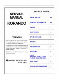
Сборник руководств на английском языке по техническому обслуживанию и ремонту + схемы электрооборудования автомобиля SsangYong Korando 1996-2006 годов выпуска.
- Автор: —
- Издательство: SsangYong
- Год издания: —
- Страниц: —
- Формат: PDF
- Размер: 321,6 Mb
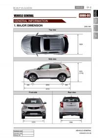
Сборник руководств на английском языке по техническому обслуживанию и ремонту + схемы электрооборудования автомобиля SsangYong Korando с 2010 года выпуска.
- Автор: —
- Издательство: SsangYong
- Год издания: 2010-2013
- Страниц: —
- Формат: PDF
- Размер: 570,0 Mb
Руководство по техническому обслуживанию и ремонту автомобилей SsangYong New Actyon и SsangYong Korando C с 2010 года выпуска с дизельным двигателем объемом 2,0 л.
- Автор: —
- Издательство: Монолит
- Год издания: —
- Страниц: 347
- Формат: PDF
- Размер: 273,2 Mb

Руководство по техническому обслуживанию и ремонту автомобилей SsangYong New Actyon и SsangYong Korando C с 2010 года выпуска с дизельным двигателем объемом 2,0 л.
- Автор: —
- Издательство: Монолит
- Год издания: —
- Страниц: 352
- Формат: —
- Размер: —

Руководство по техническому обслуживанию и ремонту автомобилей SsangYong New Actyon и SsangYong Korando C с 2010 года выпуска с дизельным двигателем объемом 2,0 л.
- Автор: —
- Издательство: Монолит
- Год издания: —
- Страниц: 376
- Формат: —
- Размер: —

Руководство по техническому обслуживанию и ремонту + каталог расходных запчастей автомобилей SsangYong Actyon и SsangYong Korando с 2011 года выпуска с бензиновыми и дизельными двигателями.
- Автор: —
- Издательство: Легион-Автодата
- Год издания: 2015
- Страниц: 491
- Формат: —
- Размер: —
Руководство по эксплуатации, техническому обслуживанию и ремонту + каталог расходных запчастей автомобилей SsangYong Korando и Tagaz Tager с бензиновыми и дизельными двигателями.
- Автор: —
- Издательство: Легион-Автодата
- Год издания: —
- Страниц: 402
- Формат: —
- Размер: —

Руководство по эксплуатации и ремонту автомобилей SsangYong Korando с 1996 и Tagaz Tager с 2008 года выпуска с бензиновыми и дизельными двигателями.
- Автор: —
- Издательство: Монолит
- Год издания: —
- Страниц: 402
- Формат: —
- Размер: —

Размещено: 2 сентября 2014
Просмотров: 7 575
Комментариев: 0
Цветное справочно-информационное иллюстрированное подробное издание руководство по ремонту SsangYong Korando C / SsangYong New Actyon, а также устройство SsangYong Korando C / SsangYong New Actyon, руководство по эксплуатации и техническому обслуживанию SsangYong Korando C / SsangYong New Actyon, которые сходят с конвейера с 2010 года и оборудуются дизельными двигателями D20DTF рабочим объемом 2,0 л. и мощностью 175 л.с.
Как и все прочие технические мануалы выполненные высококвалифицированными профессионалами, очередная ремонтная книга авторитетного издательства автолитературы Монолит расскажет владельцу Санг Енг Корандо С, Санг Енг Нью Актион как можно быстрее, применив минимум усилий с максимальной отдачей, грамотно провести любые требуемые в конкретный момент операции по диагностике повреждений (очень кстати для этой цели в руководстве представлена уникальная система определения неполадок) и ремонту всевозможных агрегатов, узлов, механизмов, замене испорченных деталей, а также непосредственно двигателя Ssang Yong Korando C / Ssang Yong New Actyon. В книге приведено необходимое описание возможных неисправностей трансмиссии, двигателя, ходовой части, тормозной системы, рулевого управления.
Материалы, которые авторы книги включили в данное пособие, окажут всеобъемлющую помощь пользователю мануала не только в гаражных условиях. Бывает происходит так, что подобные справочные данные становятся абсолютно ничем незаменимыми в дороге, особенно в такие моменты, когда техническая неприятность случается в пустынном месте и нет никого, кто смог бы выручить в столь неприятную для водителя минуту делом или четкой подсказкой. Кроме того можно великолепно применять мануал, используя его в качестве обучающего технического руководства старшим поколением для своих детей во время проведения процедур самостоятельного техосмотра, или же сидя за столом, неспеша изучая иллюстрации и комментарии к ним, в домашней обстановке. Об этом все чаще в отзывах свидетельствуют наши благодарные покупатели, многие из которых уже не раз и не два обращались к нам за книгами.
В одной из первых глав представленного ремонтного справочника помещена инструкция по эксплуатации SsangYong Korando C / SsangYong New Actyon. Важная для каждого пользователя информация по регулярному самостоятельному техническому обслуживанию SsangYong Korando C / SsangYong New Actyon, периодические проверки состояния машины, цветные схемы электрических соединений (электросхемы) SsangYong Korando C / SsangYong New Actyon, включены издателями в отдельные разделы настоящей инструкции. Помимо этого материалы издания окажут потребителю необходимую помощь в поиске нужной ему запчасти SsangYong Korando C / SsangYong New Actyon.
Язык: русский
Формат: PDF
Страниц: 347
Размер: 281,5 Мб
Скачать с
Внимание! У Вас нет прав для просмотра скрытого текста.
SSANG YONG KORANDO C / NEW ACTYON с 2010 (с учетом обновления 2012) дизель Пособие по ремонту и эксплуатации цветное
Цветное справочно-информационное иллюстрированное подробное издание руководство по ремонту SsangYong New Actyon / SsangYong Korando C, а также устройство SsangYong New Actyon / SsangYong Korando C, руководство по эксплуатации и техническому обслуживанию SsangYong New Actyon / SsangYong Korando C, которые сходят с конвейера с 2010 года и оборудуются дизельными двигателями D20DTF рабочим объемом 2,0 л. и мощностью 175 л.с.
SSANG YONG KORANDO C / ACTYON с 2012 бензин Пособие по ремонту и эксплуатации цветное
Цветная в фотографиях иллюстрированная книга по ремонту SsangYong Korando С, инструкция по эксплуатации и техническому обслуживанию, устройство Санг Йонг Корандо С с 2012 года выпуска. Руководство содержит полную информацию об автомобилях, оборудованных бензиновыми двигателями G20DF рабочим объемом 2,0 л.и мощностью 149 л.с.
SSANG YONG NEW ACTYON / KORANDO C с 2012 бензин Пособие по ремонту и эксплуатации цветное
Цветная в фотографиях иллюстрированная книга по ремонту SsangYong Actyon / Korando С, инструкция по эксплуатации и техническому обслуживанию, устройство Санг Йонг Актиона / Корандо С с 2012 года выпуска. Руководство содержит полную информацию об автомобилях, оборудованных бензиновыми двигателями G20DF рабочим объемом 2,0 л.и мощностью 149 л.с.
SSANG YONG ACTYON SPORTS с 2006 (рестайлинг 2008 и 2012) дизель Книга по ремонту и эксплуатации
Профессиональное, в фотографиях, руководство по ремонту Саньенг Актион Спорт, инструкция по эксплуатации, техническое обслуживание и устройство SsangYong Actyon Sports, поступивших в производство в 2006 году. Автомобили оборудованы дизельными двигателями D20DT (2006 г.) и D20DTR (2012 г.) рабочим объемом 2,0 л. В пособие также вошли полные данные по обновлениям модели 2008 и 2012 гг.
SSANG YONG KORANDO / NEW ACTYON с 2011 бензин/дизель 2WD; 4WDс Пособие по ремонту и эксплуатации
Справочно-техническое, в фотографиях, руководство по ремонту SsangYong Korando, инструкция по эксплуатации, техобслуживание, устройство, каталог запчастей Саньенг Корандо моделей 2WD и 4wD, поступивших в продажу с 2011 года и оборудованных бензиновыми двигателями G20DF и дизельными двигателями D20DTF рабочим объемом 2,0 л.
SSANG YONG MUSSO / TAGAZ ROAD PARTNER с 1994 и с 2000 бензин / дизель Пособие по ремонту и эксплуатации Том 1 и том 2
Руководство по ремонту, эксплуатации и техническому обслуживанию, устройство автомобилей Ssang Yong Musso / TagAZ Road Partner, оборудованных дизельными двигателями OM661 (2,3 л.) и ОМ662 (2,9 л.) и бензиновыми двигателями М161 (2,3 л.) и M162 (3,2 л.). Книги продаются в 2-х томах.
SsangYong New Actyon/Korando с 2011 бензин/дизель 2WD; 4WDс Пособие по ремонту и эксплуатации
Профессиональное, в фотографиях, руководство по ремонту SsangYong Actyon / Korando, инструкция по эксплуатации, техническое обслуживание и устройство Саньенг Актион / Корандо моделей 2WD и 4wD, поступивших в продажу с 2011 года и оборудованных бензиновыми двигателями G20DF рабочим объемом 2,0 л и дизельными двигателями D20DTF объемом 2,0 л.
SSANG YONG ACTYON с 2006-2010 бензин / дизель Мануал по ремонту и эксплуатации
Справочно-информационное иллюстрированное руководство Инструкция по ремонту Ssang Yong Actyon / Ssang Yong Actyon Sports, устройство Ssang Yong Actyon / Ssang Yong Actyon Sports, руководство по эксплуатации и техобслуживанию Ssang Yong Actyon / Ssang Yong Actyon Sports с 2006 года выпуска, оборудованных бензиновым двигателем рабочим объемом 2,3 л. (Common Rail), а также дизелем рабочим объемом 2,0 л.
SSANG YONG KORANDO C / NEW ACTYON с 2010 (с учетом обновления 2012) дизель Пособие по ремонту и эксплуатации цветное
Цветное справочно-информационное иллюстрированное подробное издание руководство по ремонту SsangYong Korando C / SsangYong New Actyon, а также устройство SsangYong Korando C / SsangYong New Actyon, руководство по эксплуатации и техническому обслуживанию SsangYong Korando C / SsangYong New Actyon, которые сходят с конвейера с 2010 года и оборудуются дизельными двигателями D20DTF рабочим объемом 2,0 л. и мощностью 175 л.с.
SSANG YONG Rexton I/Rexton II 2002-2012 бензин / дизель Пособие по ремонту и эксплуатации
Подробнейшее справочно-информационное иллюстрированное пособие руководство по ремонту SsangYong Rexton, устройство SsangYong Rexton, руководство по эксплуатации и техническому обслуживанию SsangYong Rexton с 2002 г. выпуска, включая рестайлинговые варианты модели. Эти внедорожники оборудуются бензиновыми силовыми агрегатами G23D и G32D рабочим объемом соответственно 2,3 и 3,2 л. и дизельными моторами D27DT и D27DTP (объем 2,7 л. Common Rail).
SSANG YONG ISTANA дизель Пособие по ремонту и эксплуатации
Справочно-информационное иллюстрированное издание Руководство по ремонту SsangYong Istana, устройство, руководство по эксплуатации и техническому обслуживанию Ssang Yong Istana. Модель оборудуется дизельным двигателем ОМ662 рабочим объемом 2,9 л.
SSANG YONG KYRON с 2005 и с 2007 бензин / дизель Пособие по ремонту и эксплуатации
Информационно-справочное иллюстрированное издание Книга по ремонту SsangYong Kyron, руководство по эксплуатации и техническому обслуживанию SsangYong Kyron, устройство полноприводных автомобилей SsangYong Kyron с 2005 г. выпуска (включая рестайлинг 2007 года). Модель оборудована бензиновым агрегатом G23D (2,3 л.) и дизельным двигателем D20DT (2,0 л. Common Rail).
SSANG YONG Rexton I/Rexton II с 2001 и с 2006 бензин / дизель Книга по ремонту и эксплуатации
Справочно-информационное иллюстрированное издание Руководство по ремонту Санг Йонг Рекстон, Санг Йонг Рекстон 2, а также устройство, руководство по эксплуатации и техническому обслуживанию, регулярные и периодические проверки Санг Йонг Рекстон c 2001 г. выпуска, Санг Йонг Рекстон 2 c 2006 г. выпуска, оборудованных двигателями на бензине рабочим объемом 2,3 и 3,2 л. и дизелями рабочим объемом 2,7 XDI, 2,7 XVT и 2,9 л. XDI.
SSANG YONG ACTYON / ACTYON SPORT с 2006 бензин / дизель Пособие по ремонту и эксплуатации
Справочно-информационное иллюстрированное издание Руководство по ремонту Санг Йонг Актион, Санг Йонг Актион Спорт, а также устройство, руководство по эксплуатации и техническому обслуживанию SsangYong Actyon / SsangYong Actyon Sport, которые сходят с конвейера с 2006 года и оборудуются бензиновыми двигателями E23 (G23D) рабочим объемом 2,3 л., а также дизелем D20DT рабочим объемом 2,0.
SSANG YONG ACTYON / ACTYON SPORTS / KYRON с 2005 бензин / дизель Пособие по ремонту и эксплуатации
Справочно-информационное, в которое включены иллюстрации, Руководство по ремонту Ssang Yong Actyon / Ssang Yong Actyon Sports / Ssang Yong Kyron, а также руководство по эксплуатации и процедурам по техобслуживанию, устройство Ssang Yong Actyon / Ssang Yong Actyon Sports / Ssang Yong Kyron. Эти автомобили выпускаются начиная с 2005 года и оборудуются бензиновыми двигателями рабочим объемом 2,3 (E23D, 150 л.с.), 3,2 л. (E32D, 220 л.с.) и дизелями рабочим объемом 2,0 (D20DT, 141 л.с.) и 2,7 л. (D27DT, 165 л.с.).
SSANG YONG KYRON / ACTYON / ACTYON SPORTS с 2005 бензин / дизель Руководство по ремонту и эксплуатации
Руководство по ремонту Ssang Yong Kyron / Ssang Yong Actyon / Ssang Yong Actyon Sports, а также руководство по эксплуатации и процедурам по техобслуживанию, устройство Ssang Yong Kyron / Ssang Yong Actyon / Ssang Yong Actyon Sports. Эти автомобили выпускаются начиная с 2005 года и оборудуются бензиновыми двигателями рабочим объемом 2,3 (E23D, 150 л.с.), 3,2 л. (E32D, 220 л.с.) и дизелями рабочим объемом 2,0 (D20DT, 141 л.с.) и 2,7 л. (D27DT, 165 л.с.).
SSANG YONG KYRON с 2005 / SSANG YONG KYRON II с 2007 бензин / дизель Пособие по ремонту и эксплуатации
Инструкция по ремонту Ssang Yong Kyron / Ssang Yong Kyron II, а также устройство этих моделей, руководство по эксплуатации и техническому обслуживанию автомобилей Ssang Yong Kyron / Ssang Yong Kyron II, выпуск которых производится с 2005 и с 2007 года соответственно. Машины оснащаются бензиновыми двигателями M161 и M162 рабочим объемом 2,3 и 3,2 л., а также дизелями D20DT и D27DT рабочим объемом 2,0 и 2,7 л.
SSANG YONG KORANDO, ТАГАЗ TAGER бензин / дизель Книга по ремонту и эксплуатации
Иллюстрированное информационное справочное издание Пособие по ремонту SsangYong Korando / TagAZ Tager, а также устройство, руководство по эксплуатации и техническому обслуживанию TagAZ Tager и SsangYong Korando, которые оборудовались бензиновыми двигателями M161, M162 рабочим объемом 2,3 и 3,2 л. соответственно, а также дизелями OM661, OM662 рабочим объемом соответственно 2,3 и 2,9 л.
SSANG YONG REXTON с 2002 Руководство по эксплуатации и техническому обслуживанию
Инструкция по эксплуатации и техническому обслуживанию автомобилей Ssang Yong Rexton.
SSANG YONG KORANDO KJ с 1996 / KORANDO CABRIO 1997-1999, ТАГАЗ TAGER с 2008 бензин / дизель Книга по ремонту и эксплуатации
Руководство по ремонту, эксплуатации и техническому обслуживанию автомобилей Ssang Yong Korando KJ / Korando Cabrio / ТАГАЗ Tager 1996-2008 г. выпуска, оборудованных бензиновыми двигателями E20 рабочим объемом 2,0 л., E23 рабочим объемом 2,3 л., E32 рабочим объемом 3,2 л., а также дизельными двигателями OM661LA, OM661LA Turbo рабочим объемом 2,3 л., OM662LA, OM662LA Turbo рабочим объемом 2,9 л.
SSANG YONG KYRON с 2005 дизель Пособие по ремонту и эксплуатации
Подробнейшее справочное иллюстрированное издание Руководство по ремонту Санг Енг Кайрон, устройство, руководство по эксплуатации и техническому обслуживанию Санг Енг Кайрон, которые выпускаются с 2005 года и оборудуются дизельными двигателями литражом 2,0 и 2,7.
Двигатели SSANGYONG / MERCEDES-BENZ серии 601, 602, 603, 604, 605, 606 дизель
Руководство по ремонту двигателей SsangYong / Mercedes 601, 602, 603, 604, 605, 606, устройство и техническому обслуживанию дизельных двигателей SsangYong / Mercedes 601, 602, 603, 604, 605, 606 и их модификаций.
SSANGYONG CHAIRMAN Руководство по ремонту и эксплуатации
По состоянию на сегодня пособие по ремонту, техническому обслуживанию и эксплуатации автомобилей SsangYong Chairman еще не напечатано ни одним издательством автокниги. Но Вы можете сделать на этой странице предзаказ на будущее издание
SSANGYONG RODIUS Руководство по ремонту и эксплуатации
К сожалению, на текущий момент, пособие по ремонту, техническому обслуживанию и эксплуатации автомобилей SsangYong Rodius еще не запущено в тираж ни одним автоиздательством. Но Вы можете оставить предзаказ на будущее руководство
SSANG YONG REXTON I / REXTON II с 2002 и с 2006 бензин / дизель Пособие по ремонту и эксплуатации
Руководство по ремонту, эксплуатации и техническому обслуживанию, устройство автомобилей Ssang Yong Rexton / Ssang Yong Rexton New с 2002 и с 2006 г. выпуска, южнокорейской и российской сборки, оборудованных бензиновыми двигателями R4 16V рабочим объемом 2,3 л., R5 24V рабочим объемом 3,2 л. и дизельными двигателями R5 20V Xdi Turbo рабочим объемом 2,7 л., R5 20V Turbo рабочим объемом 2,9 л.
CD SSANG YONG REXSTON / SSANG YONG NEW REXSTON с 2001 бензин / дизель
CD руководство по ремонту, техническому обслуживанию и эксплуатации автомобилей Ssang Yong Rexton / Ssang Yong New Rexton с 2001 г. выпуска, оборудованных как бензиновыми так и дизельными двигателями
CD SSANG YONG KYRON с 2005
CD руководство по ремонту, обслуживанию и эксплуатации автомобилей Ssang Yong Kyron с 2005 г. выпуска
SSANG YONG ISTANA с 1995 Пособие по эксплуатации и техническому обслуживанию
Руководство по эксплуатации и техническому обслуживанию автомобилей Ssang Yong Istana / Daewoo Istana с 1995 г. выпуска, оборудованных бензиновыми двигателями 1KZ-TE рабочим объемом 2,9 и 3,0 л.
SSANG YONG KYRON с 2006 Руководство по эксплуатации и техническому обслуживанию
Инструкция по эксплуатации и техническому обслуживанию автомобилей Ссанг Йонг Кирон с 2006 г. выпуска.
CD SSANG YONG KORANDO
CD Руководство по ремонту, эксплуатации и техническому обслуживанию автомобилей Ssang Yong Korando.
SSANG YONG ACTYON Руководство по эксплуатации и техническому обслуживанию
Руководство по эксплуатации и техническому обслуживанию автомобилей Ssang Yong Actyon.
Книга SSANG YONG KYRON (Санг Йонг Кайрон) с 2007 Руководство по ремонту в цветных фотографиях
Руководство по ремонту, эксплуатации и техническому обслуживанию автомобилей Ssang Yong Kyron с 2007 г. выпуска, оборудованных бензиновыми двигателями MB111.Е23 (2,3 л).