- Manuals
- Brands
- SSANGYONG Manuals
- Automobile
- REXTON 2006.09
- Manual
-
Contents
-
Table of Contents
-
Bookmarks
Related Manuals for SSANGYONG REXTON 2006.09
Summary of Contents for SSANGYONG REXTON 2006.09
-
Page 1: Table Of Contents
VEHICLE GENERAL 0000-00 VEHICLE GENERAL VEHICLE GENERAL 1. DIMENSIONS……..2. SPECIFICATIONS……… 3. VEHICLE IDENTIFICATION….4. MAINTENANCE ……..5. RECOMMENDED FLUIDS AND LUBRICANTS……..6. JACK-UP POINTS (DOTTED CIRCLES). 7. PIN ARRANGEMENT OF DIAGNOSTIC CONNECTOR……..8. ELECTRIC COMPONENTS AND LAYOUT……….9. TIGHTENING TORQUE OF STANDARD BOLTS…….
-
Page 3: Dimensions
01-3 0000-00 0000-00 VEHICLE GENERAL GENERAL 1. DIMENSIONS VEHICLE GENERAL undefined…
-
Page 4: Specifications
01-4 0000-00 2. SPECIFICATIONS * ( ): Optional, [ ]: 2WD, D27DTP: Diesel 2.7 Power-Up, D27DT: Diesel 2.7, G32D: Gasoline VEHICLE GENERAL undefined…
-
Page 5
01-5 0000-00 ▶Specifications (Cont’d) VEHICLE GENERAL undefined… -
Page 6: Vehicle Identification
01-6 0000-00 3. VEHICLE IDENTIFICATION 1. Engine Number 2. Chassis Number Gasoline Engine: The engine The chassis number is stamped on number is stamped on the the frame behind the front right tire. lower area of cylinder block in exhaust manifold side. 3.
-
Page 7: Maintenance
0000-00 4. MAINTENANCE 1) Diesel Engine * Use only approved Ssangyong genuine parts. Maintenance service and record retention are the owner’s responsibility. You should retain evidence that proper maintenance has been performed on your vehicle in accordance with the scheduled maintenance service chart.
-
Page 8
01-8 0000-00 * EU Countries: Only countries that belong to EU. (It does not apply to all countries in EU.) CHASSIS AND BODY Chart Symbols: I — Inspect these items and their related parts. If necessary, correct, clean, replenish, adjust or replace. -
Page 9
01-9 0000-00 * Use only approved Ssangyong genuine parts. CHASSIS AND BODY Chart Symbols: I — Inspect these items and their related parts. If necessary, correct, clean, replenish, adjust or replace. R — Replace or change. (3)* Refer to «Recommended fluids and lubricants». -
Page 10
01-10 0000-00 2) Gasoline Engine * Use only approved Ssangyong genuine parts. Maintenance service and record retention are the owner’s responsibility. You should retain evidence that proper maintenance has been performed on your vehicle in accordance with the scheduled maintenance service chart. -
Page 11
01-11 0000-00 * EU Countries: Only countries that belong to EU. (It does not apply to all countries in EU.) CHASSIS AND BODY Chart Symbols: I — Inspect these items and their related parts. If necessary, correct, clean, replenish, adjust or replace. -
Page 12
01-12 0000-00 * EU Countries: Only countries that belong to EU. (It does not apply to all countries in EU.) CHASSIS AND BODY Chart Symbols: I -Inspect these items and their related parts. If necessary, correct, clean, replenish, adjust or replace. -
Page 13: Recommended Fluids And Lubricants
0000-00 5. RECOMMENDED FLUIDS AND LUBRICANTS — Use only Ssangyong recommended fluids and lubricants. — Keep the specified levels when adding or replacing the fluids. — Do not mix any different types or brands of oils or fluids. This may cause damages.
-
Page 14: Jack-Up Points (Dotted Circles)
01-14 0000-00 6. JACK-UP POINTS (DOTTED CIRCLES) IRS type 5-link type VEHICLE GENERAL undefined…
-
Page 15: Pin Arrangement Of Diagnostic Connector
01-15 0000-00 7. PIN ARRANGEMENT OF DIAGNOSTIC CONNECTOR It is installed under the instrument panel and consists of 16 pins. The REKES key coding should be performed with SCAN-TOOLS. Diagnostic connector Functions of Terminal VEHICLE GENERAL undefined…
-
Page 16: Electric Components And Layout
01-16 0000-00 8. ELECTRIC COMPONENTS AND LAYOUT 1) Wiring Harness Arrangement VEHICLE GENERAL undefined…
-
Page 17
01-17 0000-00 2) Components Locator VEHICLE GENERAL undefined… -
Page 18: Tightening Torque Of Standard Bolts
01-18 0000-00 9. TIGHTENING TORQUE OF STANDARD BOLTS ▶Tightening Torque By Bolt Specification Metric bolt strength is embossed on the Determine extra proper tightening torque head of each bolt. The strength of bolt if tightens with washer or packing. can be classified as 4T, 7T, 8.8T, 10.9T, If tightens bolts on the below materials, 11T and 12.9T in general.
-
Page 19
01-3 1113-01 1113-01 ENGINE ASSEMBLY GENERAL 1. DESCRIPTION AND OPERATION 1) Cleanliness and Care An automobile engine is a combination of many machined, honed, polished and lapped surfaces with tolerances that are measured in the ten-thousanths of an inch. When any internal engine parts are serviced, care and cleanliness are important. A liberal coating of enigne oil should be applied to friction areas during assembly, to protect and lubricate the surfaces on initial operation. -
Page 20
01-4 1113-01 2) On-engine Service Disconnect the negative battery cable before removing or installing any electrical unit, or when a tool or equipment could easily come in contact with exposed electrical terminals. Disconnecting this cable will help prevent personal injury and damage to the vehicle. The ignition must also be in LOCK unless otherwise noted. -
Page 21
01-5 1113-01 2. G23D ENGINE ASSEMBLY Front View Rear View ENGINE ASSEMBLY undefined… -
Page 22
01-6 1113-01 LH Side View RH Side View ENGINE ASSEMBLY undefined… -
Page 23
01-7 1113-01 3. G23D ENGINE STRUCTURE Front View Side View ENGINE ASSEMBLY undefined… -
Page 24
01-8 1113-01 Front View ▶ FUNCTION FUNCTION HFM Sensor Intake Manifold Intake Air Duct Cylinder Head Cylinder Head Cover Exhaust Manifold Ignition Coi Dipstick Guide Tube and Gauge Spark Plug Connector Connecting Rod Fuel Distributor Crankshaft Injector Engine Mounting Bracket Exhaust Camshaft Starter Intake Camshaft… -
Page 25
01-9 1113-01 4. DIAGNOSTIC INFORMATION AND PROCEDURE 1) Oil Leak Diagnosis Most fluid oil leaks are easily located and repaired by visually finding the leak and replacing or repairing the necessary parts. On some occasions a fluid leak may be difficult to locate or repair. -
Page 26
01-10 1113-01 ▶ Black Light and Dye Method A dye and light kit is available for finding leaks, Refer to the manufacturer’s directions when using the kit. Pour the specified amount of dye into the engine oil fill tube. Operate the vehicle normal operating conditions as directed in the kit. Direct the light toward the suspected area. -
Page 27
01-11 1113-01 2) Compression Pressure Test ▶ Standard Service Data A9912 0012B (001 589 76 21 00) Compression Pressure Tester Measuring Procedure ▶ Warm the engine up to normal operating temperature. Remove the spark plugs using the spark plug wrench. Place the diagram sheet to compression pressure tester A9912 0012B (001 589 76 21 00). -
Page 28
01-12 1113-01 3) Cylinder Pressure LeakageTest ▶ Permissible Pressure Leakage At Whole Engine Max. 25 % At Valve and Cylinder Head Gasket Max. 10 % At Piston and Piston Ring Max. 20 % Cylinder Number ▶ 1, 4 OT (TDC) 2, 3 UT (BDC 180 °) ▶… -
Page 29
01-13 1113-01 ▶ Leakage Test Warm the engine up to normal operating temperature. Disconnect the negative battery cable. Remove the spark plugs. Check the coolant level by opening the coolant reservoir cap and replenish if insufficient. Open the engine oil filler cap. Connect the tester to air pressure line and adjust the scale of tester. -
Page 30
01-14 1113-01 5. GENERAL DIAGNOSIS ENGINE ASSEMBLY undefined… -
Page 31
01-15 1113-01 ▶ General Diagnosis (Cont’d) ENGINE ASSEMBLY undefined… -
Page 32
01-16 1113-01 ▶ General Diagnosis (Cont’d) ENGINE ASSEMBLY undefined… -
Page 33
01-17 1113-01 ▶ General Diagnosis (Cont’d) ENGINE ASSEMBLY undefined… -
Page 34
01-18 1113-01 ▶ General Diagnosis (Cont’d) ENGINE ASSEMBLY undefined… -
Page 35
01-19 1113-01 6. SPECIFICATIONS 1) Engine Specifications MSE : Engine Control Module 3.53D : 4 Cylinder Version ENGINE ASSEMBLY undefined… -
Page 36
01-20 1113-01 2) Fastener Tightening Specifications ENGINE ASSEMBLY undefined… -
Page 37
01-21 1113-01 ▶ Fastener Tightening Specifications (Cont’d) ENGINE ASSEMBLY undefined… -
Page 38
01-22 1113-01 2) Performance Curve ENGINE ASSEMBLY undefined… -
Page 40
02-3 1713-08 0000-00 ENGINE INTAKE SYSTEM GENERAL 1. SPECIFICATIONS (1) Fastener Tightening Specifications ENGINE INTAKE SYSTEM undefined… -
Page 41
03-3 2420-01 2420-01 ENGINE EXHAUST SYSTEM GENERAL 1. SPECIFICATION (1) Fastener Tightening Specifications ENGINE EXHAUST SYSTEM undefined… -
Page 42
03-4 2420-01 OVERVIEW AND OPERATION PROCESS 1. DESCRIPTION AND OPERATION 1) Exhaust System When you are inspecting or replacing exhaust system components, make sure there is adequate clearance from all points on the underbody to avoid possible overheating of the floor panel and possible damage to the passenger compartment insulation and trim materials. -
Page 43
03-5 2420-01 ▶ Catalytic Converter and Temperature Catalytic converter has the normal function of purification at a range of the temperature. Because it has a weak point of decreasing of the purification rate in the condition of continuous high temperature, it should keep the temperature range of 400 to 500°C normal condition. -
Page 44
03-6 2420-01 ▶ Method for Reduction of NOx NOx is generated a great deal in case that combustion temperature and excess air factor are high. EGR valve can decrease NOx (30 to 35% decrease) by making temperature of combustion chamber fall by means of exhaust gas re-circulation. EGR valve is installed on the diesel engine of Musso, Korando, Istana and Rexton. -
Page 45
04-3 2110-01 2110-01 ENGINE COOLING SYSTEM GENERAL 1. GENERAL SPECIFICATIONS ENGINE COOLING SYSTEM undefined… -
Page 46
04-4 2110-01 2. FASTENER TIGHTENING SPECIFICATIONS ENGINE COOLING SYSTEM undefined… -
Page 47
04-5 2110-01 OVERVIEW AND OPERATION PROCESS 1. COMPONENT LOCATOR 1. Reserver Tank 9. Radiator 2. Deaeration Tube 10. Lower Radiator Insulator 3. Inlet Hose 11. Plate 4. Outlet Hose 12. Clip 5. 3 way Hose 13. Upper Radiator Insulator 6. Clamp 14. -
Page 48
04-6 2110-01 2. DESCRIPTION AND OPERATION 1) General Description The cooling system maintains the engine temperature at an efficient level during all engine operating conditions. When the engine is cold, the cooling system cools the engine slowly or not at all. This slow cooling of the engine allows the engine to warm up quickly. -
Page 49
04-7 2110-01 4) Water Pump The belt-driven centrifugal water pump consists of an impeller, a drive shaft, and a belt pulley. The impeller is supported by a completely sealed bearing. The water pump is serviced as an assembly and, therefore, cannot be disassembled. 5) Thermostat A wax pellet-type thermostat controls the flow of the engine coolant through the engine cooling system. -
Page 50
04-8 2110-01 The cooling fans are mounted behind the radiator in the engine compartment. The electric cooling fans increase the flow of air across the radiator fins and across the condenser on air conditioned (A/C)-equipped vehicles. This helps to speed cooling when the vehicle is at idle or moving at low speeds. All models have two fans. -
Page 51
04-9 2110-01 3. PWM (PULSE WIDTH MODULATION) ELECTRIC FAN OPERATION 1) Function The PWM (Pulse Width Modulation) high capacity electric fan is installed instead of electric condenser fan to enhance the durability and controllability and reduce noise. 2) Mounting Location Fan shroud PWM unit Electric fan… -
Page 52
04-10 2110-01 3) PWM Electric Fan (1) Advantages and Disadvantages of the PWM Electric Fan ▶ Advantages Enhanced A/C performance: at low speed, at idling, driving in city Reduction vibration/noise: activated by PWM only when necessary Reduction of engine consuming power (V/Fan driving force) by 4 Hp — Cost saving ▶… -
Page 53
04-11 2110-01 5) Shutting-off Condition of the A/C Compressor Coolant temperature ▶ When coolant temperature is below 20°C or over 115°C, engine speed is below 650 rpm or over 4500 rpm for 4 seconds after engine starting, abrupt acceleration and A/C refrigerant pressure sensor detecting the followings A/C compressor is turned off when the refrigerant pressure is below 2.0 kg/cm2 and then is turned on when the refrigerant pressure is over 2.4 kg/cm2. -
Page 54
05-3 1452-01 0000-00 ENGINE ELECTRIC DEVICES GENERAL 1. DIAGNOSTIC INFORMATION AND PROCEDURE 1) Ignition System ENGINE ELECTRICAL SYSTEM undefined… -
Page 55
05-4 1452-01 2) Ignition System (Cont’d) ENGINE ELECTRICAL SYSTEM undefined… -
Page 56
05-5 1452-01 OVERVIEW AND OPERATION PROCESS 1. DESCRIPTION AND OPERATION 1) Battey The sealed battery is standard on all cars. There are no vent plugs in the cover. The battery is completely sealed, except for two small vent holes in the sides. These vent holes allow the small amount of gas produced in the battery to escape. -
Page 57
05-6 1452-01 (2) Cold Cranking Amperage The cold cranking amperage test is expressed at a battery temperature of -18 °C (0 °F). The current rating is the minimum amperage, which must be maintained by the battery for 30 seconds at the specified temperature, while meeting a minimum voltage requirement of 7.2 volts. -
Page 58
05-7 1452-01 4) Charging a Completely Discharged Battery (Off the Vehicle) Unless this procedure is properly followed, a perfectly good battery may be needlessly replaced. The following procedure should be used to recharge a completely discharged battery: Measure the voltage at the battery terminals with an accurate voltmeter. If the reading is below 10 volts, the charge current will be very low, and it could take some time before the battery accepts the current in excess of a few milliamperes. -
Page 59
05-8 1452-01 5) Jump Starting Procedure Position the vehicle with the charged battery so that the jumper cables will reach from the charged battery to the battery that requires charging. Turn off the ignition, all the lights, and all the electrical loads in both vehicles. Leave the hazard flasher on if jump starting where there may be other traffic and any other lights needed for the work area. -
Page 60
05-9 1452-01 6) Alternator Alternators are equipped with internal regulators. Unlike three-wire generators, the alternator may be used with only two connections: battery positive and an «D+» terminal to the charge indicator lamp. As with other charging systems, the charge indicator lamp lights when the ignition switch is turned to RUN, and goes out when the engine is running. -
Page 61
05-10 1452-01 9) Starting System The engine electrical system includes the battery, the ignition, the starter, the generator, and all the related wiring. Diagnostic tables will aid in troubleshooting system faults. When a fault is traced to a particular component, refer to that component section of the service manual. The starting system circuit consists of the battery, the starter motor, the ignition switch, and all the related electrical wiring. -
Page 62
06-3 8510-23 8510-23 CRUISE CONTROL SYSTEM OVERVIEW AND OPERATION PROCESS 1. CRUISE CONTROL SWITCH The purpose of the cruise control system is to automatically maintain a vehicle speed set by the driver, without depressing the accelerator pedal. The cruise control switch is located under the right side of the steering wheel, and when this switch is operating «AUTO CRUISE»… -
Page 63
06-4 8510-23 1) When To Use Use the cruise control system only when (a) the traffic is not jammed, (b) driving on motorways or highways where there is no sudden change in the driving condition due to traffic lights, pedestrian, etc. Use the cruise control system only when driving on motorways or highways. -
Page 64
06-5 8510-23 2. CIRCUIT DIAGRAM 1) Configuration CRUISE CONTROL SYSTEM undefined… -
Page 65
06-6 8510-23 3. HOW TO OPERATE CRUISE CONTROL SWITCH 1) How To Set Speed To operate the cruise control system, accelerate the vehicle to the speed within the specified range below with depressing the accelerator pedal. — Cruise control operating range: between 36 km/h (22.37 mph) and 150 km/h (93.207 mph) When the desired speed is reached, which should be within the above range, push up the cruise control switch lever to ACCEL side (upwards arrow), or push down the switch lever to DECEL side (downwards arrow). -
Page 66
06-7 8510-23 2) Accelerating with the Cruise Control System (1) While the cruise control system is running To increase the set speed, push up the cruise control switch lever to ACCEL side and hold it until the desired speed is reached without depressing the accelerator pedal. When the desired speed is set, release the switch lever. -
Page 67
06-8 8510-23 3) Decelerating with the Cruise Control System (1) While the cruise control system is running To decrease the set speed, push down the cruise control switch lever to DECEL side and hold it until the desired speed is reached without depressing the brake pedal. But the cruise control system cannot maintain the cruise function at less than 34 km/h (21.13 mph). -
Page 68
06-9 8510-23 4) Recovery of Set Speed (RESUME) Even if the cruise control is cancelled, the previous set cruise speed can be recovered by operating the cruise control switch lever like below: — Pull the switch lever in the arrow direction shown in the illustration. This RESUME function works only when the vehicle speed is more than 36 km/h (22.37 mph) without using the accelerator or brake pedal. -
Page 69
06-10 8510-23 5) Normal Cancellation of the Cruise Control (OFF ↔ ON) The cruise control system will be cancelled when the button on the side of the switch is pressed, or when one of the following conditions is met: When the brake pedal is depressed or ESP is activated. When the vehicle speed is less than 34 km/h (21.13 mph). -
Page 70
ENGINE INFORMATION 0000-00 ENGINE INFORMATION GENERAL 1. COMPONENT LOCATOR……. 2. DESCRIPTION AND OPERATION.. -
Page 73
01-4 0000-00 0000-00 ENGINE GENERAL GENERAL 1. COMPONENT LOCATOR 1) Front View ENGINE INFORMATION undefined… -
Page 74
01-5 0000-00 ▶ Front View FUNCTION FUNCTION HFM sensor Intake manifold Intake air duct Connecting rod Resonance flap Exhaust manifold Cylinder head cover Crankshaft Exhaust camshaft Engine mounting Intake camshaft Starter Cylinder head Crankcase Spark plug connector Oil pump sprocket Valve tappet Oil strainer Injector… -
Page 75
01-6 0000-00 2) SIDE VIEW FUNCTION FUNCTION Camshaft adjuster Oil pump drive chain Cooling fan and viscous clutch Oil return pipe Piston Timing chain Flywheel of drive plate ENGINE INFORMATION undefined… -
Page 76
01-7 0000-00 2. DESCRIPTION AND OPERATION 1) Cleanliness And Care An automobile engine is a combination of many machined, honed, polished and lapped surfaces with tolerances that are measured in the ten-thousanths of an inch. When any internal engine parts are serviced, care and cleanliness are important. A liberal coating of enigne oil should be applied to friction areas during assembly, to protect and lubricate the surfaces on initial operation. -
Page 78
02-3 1113-01 1113-01 ENGINE ASSEMBLY GENERAL 1. SPECIFICATIONS 1) ENGINE SPECIFICATIONS ENGINE ASSEMBLY undefined… -
Page 79
02-4 1113-01 2) PERFORMANCE CURVE ENGINE ASSEMBLY undefined… -
Page 80
02-5 1113-01 2. SPECIAL TOOLS AND EQUIPMENT ENGINE ASSEMBLY undefined… -
Page 81
02-6 1113-01 ENGINE ASSEMBLY undefined… -
Page 82
02-7 1113-01 Name and Part Number A9917 0012B (DW110-120)Holding Pin ENGINE ASSEMBLY undefined… -
Page 83
02-8 1113-01 3. FASTENER TIGHTENING SPECIFICATIONS ENGINE ASSEMBLY undefined… -
Page 84
02-9 1113-01 1) Fastener Tightening Specifications (Cont’d) ENGINE ASSEMBLY undefined… -
Page 85
03-3 2211-22 2211-22 ENGINE FUEL SYSTEM OVERVEIW AND OPERATION PROCESS 1. FUEL SYSTEM SPECIFICATION ▶ Use Only Unleaded Fuel Rated at 89 Octane or Higher Fuel quality and additives contained in fuel have a significant effect on power output, drivability, and life of theengine. -
Page 86
03-4 2211-22 ▶ Temperature vs resistance ENGINE FUEL SYSTEM undefined… -
Page 87
NO DATA… -
Page 88
05-3 2420-01 2420-01 ENGINE EXHAUST SYSTEM GENERAL 1. OVERVIEW OF EXHAUST SYSTEM When you are inspecting or replacing exhaust system components, make sure there is adequate clearance from all points on the underbody to avoid possible overheating of the floor panel and possible damage to the passenger compartment insulation and trim materials. -
Page 89
05-4 2420-01 4. FASTENER TIGHTENING SPECIFICATIONS ENGINE EXHAUST SYSTEM undefined… -
Page 90
06-3 9210-01 9210-01 ENGINE LUBRICATION SYSTEM OVERVIEW AND OPERATION PROCESS 1. OIL CIRCULATION LUBRICATION SYSTEM undefined… -
Page 91
06-4 9210-01 ▶ OIL CIRCULATION FUNCTION FUNCTION Oil pump Oil supply (to exhaust camshaft) Oil gallery (to oil filter) Oil supply (to intake camshaft) Oil supply Oil filter (to exhaust camshaft bearing) Oil supply Oil pressure switch (to intake camshaft bearing) Oil gallery Main oil gallery (oil supply to exhaust valve tappet) -
Page 92
07-3 2110-01 2110-01 ENGINE COOLING SYSTEM GENERAL 1. GENERAL SPECIFICATIONS COOLING SYSTEM undefined… -
Page 93
07-4 2110-01 2. SPECIAL TOOLS AND EQUIPMENT COOLING SYSTEM undefined… -
Page 94
07-5 2110-01 3. FASTENER TIGHTENING SPECIFICATIONS COOLING SYSTEM undefined… -
Page 95
07-6 2110-01 OVERVIEW AND OPERATION PROCESS 1. GENERAL DESCRIPTION The cooling system maintains the engine temperature at an efficient level during all engine operating conditions. When the engine is cold, the cooling system cools the engine slowly or not at all. This slow cooling of the engine allows the engine to warm up quickly. The cooling system includes a radiator and recovery subsystem, cooling fans, a thermostat and housing, a water pump, and a water pump drive belt. -
Page 96
07-7 2110-01 2. COMPONENT LOCATOR COOLING SYSTEM undefined… -
Page 97
07-8 2110-01 Radiator Inlet hose Electric fan Outlet hose Shroud 3 way hose Deaeration tube Deaeration hose (reserver tank) Clamp Clamp Deaeration hose (radiator) Clamp Electric fan mounting bracket Make up hose holder Bolt (M6, 8 pieces) Reserver tank Bolt (M6, 4 pieces) Bolt (M6, 2 piece) Bolt (M6, 4 pieces) Cooling fan… -
Page 98
08-3 1452-01 1452-01 ENGINE ELECTRIC DEVICES GENERAL 1. GENERAL SPECIFICATIONS ENGINE ELECTRIC DEVICES undefined… -
Page 99
08-4 1452-01 2. FASTENER TIGHTENING SPECIFICATIONS ENGINE ELECTRIC DEVICES undefined… -
Page 100
08-5 1452-01 OVERVIEW AND OPERATION PROCESS 1. CHARGING SYSTEM OPERATION Alternators use a new type of regulator that incorpo-rates a diode trio. A Delta stator, a rectifier bridge, and a rotor with slip rings and brushes are electrically similar to earlier alternators. A conventional pulley and fan are used. -
Page 101
08-6 1452-01 3. IGNITION SYSTEM OPERATION This ignition system does not use a conventional distributor and coil. It uses a crankshaft position sensor input to the Engine Control Module (ECM). The ECM then determines Electronic Spark Timing (EST) and triggers the electronic ignition system ignition coil. -
Page 102
08-7 1452-01 4. STARTING AND CHARGING SYSTEM (GASOLINE ENGINE) CIRCUIT ENGINE ELECTRIC DEVICES undefined… -
Page 103
09-3 1522-16 1522-16 ENGINE CONTROL SYSTEM GENERAL 1. ENGINE DATA DISPLAY TABLE ENGINE CONTROL SYSTEM undefined… -
Page 104
09-4 1522-16 1) TEMPERATURE VS RESISTANCE 2. FASTENER TIGHTENING SPECIFICATIONS ENGINE CONTROL SYSTEM undefined… -
Page 105
10-3 8510-23 8510-23 CRUISE CONTROL SYSTEM OVERVIEW AND OPERATION PROCESS 1. CRUISE CONTROL SWITCH The purpose of the cruise control system is to automatically maintain a vehicle speed set by the driver, without depressing the accelerator pedal. The cruise control switch is located under the right side of the steering wheel, and when this switch is operating «AUTO CRUISE»… -
Page 106
10-4 8510-23 1) When To Use Use the cruise control system only when (a) the traffic is not jammed, (b) driving on motorways or highways where there is no sudden change in the driving condition due to traffic lights, pedestrian, etc. Use the cruise control system only when driving on motorways or highways. -
Page 107
10-5 8510-23 2. CIRCUIT DIAGRAM 1) Configuration CRUISE CONTROL SYSTEM undefined… -
Page 108
10-6 8510-23 3. HOW TO OPERATE CRUISE CONTROL SWITCH 1) How To Set Speed To operate the cruise control system, accelerate the vehicle to the speed within the specified range below with depressing the accelerator pedal. — Cruise control operating range: between 36 km/h (22.37 mph) and 150 km/h (93.207 mph) When the desired speed is reached, which should be within the above range, push up the cruise control switch lever to ACCEL side (upwards arrow), or push down the switch lever to DECEL side (downwards arrow). -
Page 109
10-7 8510-23 2) Accelerating with the Cruise Control System (1) While the cruise control system is running To increase the set speed, push up the cruise control switch lever to ACCEL side and hold it until the desired speed is reached without depressing the accelerator pedal. When the desired speed is set, release the switch lever. -
Page 110
10-8 8510-23 3) Decelerating with the Cruise Control System (1) While the cruise control system is running To decrease the set speed, push down the cruise control switch lever to DECEL side and hold it until the desired speed is reached without depressing the brake pedal. But the cruise control system cannot maintain the cruise function at less than 34 km/h (21.13 mph). -
Page 111
10-9 8510-23 4) Recovery of Set Speed (RESUME) Even if the cruise control is cancelled, the previous set cruise speed can be recovered by operating the cruise control switch lever like below: — Pull the switch lever in the arrow direction shown in the illustration. This RESUME function works only when the vehicle speed is more than 36 km/h (22.37 mph) without using the accelerator or brake pedal. -
Page 112
10-10 8510-23 5) Normal Cancellation of the Cruise Control (OFF ↔ ON) The cruise control system will be cancelled when the button on the side of the switch is pressed, or when one of the following conditions is met: When the brake pedal is depressed or ESP is activated. When the vehicle speed is less than 34 km/h (21.13 mph). -
Page 113
ENGINE GENERAL 0000-00 ENGINE GENERAL GENERAL 1. STRUCTURE AND COMPARISON..2. ENGINE SPECIFICATIONS AND PERFORMANCE CURVE……3. TIGHTENING TORQUE……4. MAJOR CHANGES IN D27DTP(POWER UP ENGINE(COMPARED TO D27DT)..OERVIEW AND OPERATION PROCESS 1. ENGINE COMPARTMENT….. 2. SYSTEM IN ENGINE COMPARTMENT. -
Page 115: Structure And Comparison
01-3 0000-00 0000-00 ENGINE GENERAL GENERAL 1. STRUCTURE AND COMPARISON ▶D27DT (EU IV) Engine — Front View ▶D27DT (EU IV) Engine — Top View ENGINE GENERAL undefined…
-
Page 116
01-4 0000-00 ▶D27DT (EU IV) Engine — Side View ▶D27DT (EU IV) Engine — Left Side View ENGINE GENERAL undefined… -
Page 117
01-5 0000-00 ▶D27DT Engine (General) — Front View ▶D27DT Engine (General) — Top View ENGINE GENERAL undefined… -
Page 118
01-6 0000-00 ▶D27DT Engine (General) — Side View ▶D27DT Engine (General) — Left Side View ENGINE GENERAL undefined… -
Page 119: Engine Specifications And Performance Curve
01-7 0000-00 2. ENGINE SPECIFICATIONS AND PERFORMANCE CURVE 1) Specifications ENGINE GENERAL undefined…
-
Page 120
01-8 0000-00 2) D27DT Engine Performance Curve (1) Output and Torque (2) Oil Temperature/Pressure and Boost Pressure ENGINE GENERAL undefined… -
Page 121: Tightening Torque
01-9 0000-00 3. TIGHTENING TORQUE This table shows the tightening torques for removal/mounting and disassembly/reassemly of the engine. ENGINE GENERAL undefined…
-
Page 122
01-10 0000-00 ENGINE GENERAL undefined… -
Page 123
01-11 0000-00 ENGINE GENERAL undefined… -
Page 124: Major Changes In D27Dtp(Power Up Engine(Compared To D27Dt)
01-12 0000-00 MAJOR CHANGES IN D27DTP (POWER UP) ENGINE (COMPARED TO D27DT) The shape and size of D27DTP (POWER UP) are slightly different from those of D27DT engine but the basic configuration of two systems is almost same. 1) Engine Assembly ENGINE GENERAL undefined…
-
Page 125
01-13 0000-00 2) Major Changes and Summary ENGINE GENERAL undefined… -
Page 126
01-14 0000-00 ENGINE GENERAL undefined… -
Page 127
01-15 0000-00 ENGINE GENERAL undefined… -
Page 128
01-16 0000-00 ENGINE GENERAL undefined… -
Page 129
01-17 0000-00 ENGINE GENERAL undefined… -
Page 130
01-18 0000-00 ENGINE GENERAL undefined… -
Page 131
01-19 0000-00 ENGINE GENERAL undefined… -
Page 132
01-20 0000-00 ENGINE GENERAL undefined… -
Page 134: Engine Compartment
01-22 0000-00 OVERVIEW AND OPERATION PROCESS 1. ENGINE COMPARTMENT The major changes due to the newly adopted engine compared to D27DT engine are as follows: ENGINE GENERAL undefined…
-
Page 135
01-23 0000-00 ENGINE GENERAL undefined… -
Page 136
01-24 0000-00 ▶Engine Compartment Layout Engine assembly FFH Assembly (Only for vehicle with FFH) Engine oil dipstick Power steering oil tank Vacuum pump Engine oil filler cap Oil filter and cooler Fan shroud Fuel filter and priming pump E-EGR Valve Brake booster High-capacity PCV oil separator Brake oil tank… -
Page 137
01-25 0000-00 ▶Major Sensors and Components ENGINE GENERAL undefined… -
Page 138: System In Engine Compartment
01-26 0000-00 2. SYSTEMS IN ENGINE COMPARTMENT 1) Engine Accessories Related to ECU ENGINE GENERAL undefined…
-
Page 139
01-27 0000-00 ENGINE GENERAL undefined… -
Page 140
01-28 0000-00 2) Preheat System ENGINE GENERAL undefined… -
Page 141
01-29 0000-00 3) Fuel System ENGINE GENERAL undefined… -
Page 142
01-30 0000-00 ▶Fuel Supply System ENGINE GENERAL undefined… -
Page 143
01-31 0000-00 4) Lubrication System ENGINE GENERAL undefined… -
Page 144
01-32 0000-00 5) Cooling System ENGINE GENERAL undefined… -
Page 145
01-33 0000-00 6) Intake System ENGINE GENERAL undefined… -
Page 146
01-34 0000-00 7) Exhaust System ENGINE GENERAL undefined… -
Page 147
02-3 1881-09 1881-09 ENGINE FUEL SYSTEM OVERVIEW AND OPERATION PROCESS MAJOR CHANGES IN FUEL SYSTEM OF D27DTP (POWER UP) ENGINE There are some changes in the parts related to the fuel system due to the newly adopted D27DTP (POWER UP) engine. The major changes are as follows. Refer to the next pages for further details. -
Page 148
02-4 1881-09 2) Common Rail The orifice is added to the connection to · D27DTP & D27DT (EU IV) the fuel pipe of the HP pump to prevent the fuel pulsation by the fuel supply and fuel cut according to the increase of injected fuel volume. -
Page 149
02-5 1881-09 3) Fuel Rail — Chrome Color · The I.D and O.D of the fuel rail between D27DTP & D27DT (EU IV) HP pump and common rail are increased * Fuel pipe (Common rail → Injector) according to the increased amount of fuel injection. -
Page 150
02-6 1881-09 2. COMPONENTS OF FUEL SYSTEM ENGINE FUEL SYSTEM undefined… -
Page 151
02-7 1881-09 ▶Fuel Flow of D27DTP (Power Up) Engine Fuel Supply System ENGINE FUEL SYSTEM undefined… -
Page 152
03-3 2321-01 2321-01 ENGINE INTAKE SYSTEM OVERVIEW AND OPERATION PROCESS 1. INTAKE SYSTEM LAYOUT The intake system for the D27DTP (POWER UP) engine is equipped with the throttle body that has a flap to block the air coming to the engine when the engine is switched off. Therefore, the structure of the intake manifold has been changed. -
Page 153
04-3 1792-01 1792-01 ENGINE EXHAUST SYSTEM OVERVIE AND OPERATION PROCESS 1. COMPONENTS The components of the exhaust system for the D27DTP (POWER UP) engine have been changed as follows: 1. E-EGR valve: Controlling the EGR valve electrically and sends the valve location signal to ECU (vacuum modulator control has been deleted) 2. -
Page 154
05-3 1725-12 1725-12 CDPF(Catalytic Disel Particulate Filter) GENERAL 1. Specifications for engine with CDPF CDPF(Catalytic Disel Particulate Filter) undefined… -
Page 155
05-4 1725-12 OVERVIEW AND OPERATION PROCESS 1. OVERVIEW As the solution for environmental regulations and PM Particla Material) of diesel engine, the low emission vehicle is getting popular. This vehicle is equipped with an extra filter to collect the soot and burn it again so that the amount of PM in the exhaust gas passed through the DOC (Diesel Oxydation Catalyst) is reduced. -
Page 156
05-5 1725-12 2. COMPONENTS Differential Pressure CDPF Assembly and Rear Exhaust Gas Temperatiure Sensor Sensor CDPF(Catalytic Disel Particulate Filter) undefined… -
Page 157
05-6 1725-12 3. MAJOR CHANGES The CDPF system is only installed to the D27DT engine, and the major changes comparing to the previous D27DT engine is as follows: CDPF (Catalyst & Diesel Particulate Filter) and Sensors Engine ECU Fuel Common Rail and Fuel Rail (Between Common Rail and Injector) The engine ECU has been revised since The I.D and O.D of fuel rail has changed… -
Page 158
05-7 1725-12 CDPF(Catalytic Disel Particulate Filter) undefined… -
Page 159
05-8 1725-12 4. OPERATION PROCESS 1) Combustion Temperature and Procedures As the soot is filtered in the CDPF, it is burnt and removed, and the CDPF is returned to the initial state to collect the soot. Therefore, the burning procedures in the CDPF can be called as recycling. -
Page 160
05-9 1725-12 2) Sytem Composition for Soot Combustion When the engine is running in low load range, the temperature of exhaust gas is decreased as the amount of fuel supplied is decreased. To burnt the soot filtered in the CDPF, the control system should be installed to check the operating range and increase the temperature of exhaust gas by controlling the amount of fuel supplied and and intake air. -
Page 161
05-10 1725-12 4) Throttle Body for Different Engines The throttle body is not installed in the D27DT engine (general), but is installed in the following engines: 1) D27DT (EU IV) engine 2) D27DTP (POWER UP) engine 3) D27DTP (POWER UP) engine + CDPF Both engines are equipeed with the throttle body, but its appearance and the related control system are differ. -
Page 162
05-11 1725-12 5) Operating Procedures of CDPF The most efficient and practical technology for now is adopted to the diesel particulate filter (DPF). This system collects the soot from the diesel engine to the filter and burns the soot so that over than 95% of soot can be removed from the exhaust gas. -
Page 163
05-12 1725-12 6) CDPF Over Load (Notice of Beginning CPF Regeneration Mode — P1430) The CDPF system enters the regeneration mode when the mileage is around 600 ~ 1,200 km, depending on the driving condition and driving habits. At this moment, the ECU performs the CDPF regeneration process;… -
Page 164
NO DATA… -
Page 165
07-3 1520-01 1520-01 ENGINE COOLING SYSTEM OVERVIEW AND OPERATION PROCESS 1. COMPARISON IN COOLING SYSTEM FOR EACH ENGINE For the D27DTP (POWER UP) engine, the cooling system is equipped with E-EGR cooler and the water pump which its capacity is improved according to the additional coolant line in the cylinder block. -
Page 166
07-4 1520-01 ▶Comparison D27DTP (POWER UP) & D27DT (EU IV) Engine D27DT Engine ENGINE COOLING SYSTEM undefined… -
Page 167
NO DATA… -
Page 168
NO DATA… -
Page 169
10-3 8510-23 8510-23 CRUISE CONTROL SYSTEM OVERVIEW AND OPERATION PROCESS 1. CRUISE CONTROL SWITCH The purpose of the cruise control system is to automatically maintain a vehicle speed set by the driver, without depressing the accelerator pedal. The cruise control switch is located under the right side of the steering wheel, and when this switch is operating «AUTO CRUISE»… -
Page 170
10-4 8510-23 1) When To Use Use the cruise control system only when (a) the traffic is not jammed, (b) driving on motorways or highways where there is no sudden change in the driving condition due to traffic lights, pedestrian, etc. Use the cruise control system only when driving on motorways or highways. -
Page 171
10-5 8510-23 2. CIRCUIT DIAGRAM 1) Configuration CRUISE CONTROL SYSTEM undefined… -
Page 172
10-6 8510-23 3. HOW TO OPERATE CRUISE CONTROL SWITCH 1) How To Set Speed To operate the cruise control system, accelerate the vehicle to the speed within the specified range below with depressing the accelerator pedal. — Cruise control operating range: between 36 km/h (22.37 mph) and 150 km/h (93.207 mph) When the desired speed is reached, which should be within the above range, push up the cruise control switch lever to ACCEL side (upwards arrow), or push down the switch lever to DECEL side (downwards arrow). -
Page 173
10-7 8510-23 2) Accelerating with the Cruise Control System (1) While the cruise control system is running To increase the set speed, push up the cruise control switch lever to ACCEL side and hold it until the desired speed is reached without depressing the accelerator pedal. When the desired speed is set, release the switch lever. -
Page 174
10-8 8510-23 3) Decelerating with the Cruise Control System (1) While the cruise control system is running To decrease the set speed, push down the cruise control switch lever to DECEL side and hold it until the desired speed is reached without depressing the brake pedal. But the cruise control system cannot maintain the cruise function at less than 34 km/h (21.13 mph). -
Page 175
10-9 8510-23 4) Recovery of Set Speed (RESUME) Even if the cruise control is cancelled, the previous set cruise speed can be recovered by operating the cruise control switch lever like below: — Pull the switch lever in the arrow direction shown in the illustration. This RESUME function works only when the vehicle speed is more than 36 km/h (22.37 mph) without using the accelerator or brake pedal. -
Page 176
10-10 8510-23 5) Normal Cancellation of the Cruise Control (OFF ↔ ON) The cruise control system will be cancelled when the button on the side of the switch is pressed, or when one of the following conditions is met: When the brake pedal is depressed or ESP is activated. When the vehicle speed is less than 34 km/h (21.13 mph). -
Page 177
NO DATA… -
Page 178
02-3 8710-08 8710-08 RKSTICS GENERAL 1. SPECIFICATIONS 1) Electrical Performance 2) Characteristics of Radio Wave Transmitting frequency: 447.800 ± 0.0125 MHz Channel width: below 12.5 KHz Frequency bandwidth: below 8.5 KHz Modulation method: FSK (Frequency Shift Keying) Receiving distance: Approx. 10 ~ 15 m (In case there are not obstacles around the system) RKSTICS… -
Page 179
02-4 8710-08 3) Rated Load RKSTICS undefined… -
Page 180
02-5 8710-08 4) Input Signals RKSTICS undefined… -
Page 181
02-6 8710-08 5) Chattering of Input Signals Vehicle speed input: The vehicle speed is the average value of 4 pulse among 6 pulse inputs regardless of the input for 1.0 second after IGI 1 ON. The time indicated in each function does not include the vehicle speed calculating time. -
Page 182
02-7 8710-08 OVERVIEW AND OPERATION PROCESS 1. OVERVIEW The RKSTICS (REKES + STICS (Super Time & Integrated Control System)) communicates with the transmitter (remote controller) and other electronic systems to transmit and receive the data. The STICS also includes a diagnosis function that can inspect the error for related devices. 2. -
Page 183
02-8 8710-08 3. FUNCTIONS ▶ Wiper and Washer Operations RKSTICS undefined… -
Page 184
02-9 8710-08 ▶ Wiper MIST and Front Washer Coupled Wiper The wiper relay is turned on at 0.3 seconds after from the time when the washer switch is turned on for 0.1 to 0. 59 seconds (T2) with the ignition switch «ON», . If the wiper parking terminal gets off, the wiper relay is turned off. -
Page 185
02-10 8710-08 When the washer switch is turned on for more than 0.6 seconds during the wiper operation by AUTO switch, the wiper operates three times. When it is turned on for a certain period of time (0.1 to 0.59 seconds), the wiper operates once. RKSTICS undefined… -
Page 186
02-11 8710-08 ▶ Auto Washer and Wiper Switch When the auto washer switch is turned on with the ignition switch «ON» and the AUTO switch «OFF», the washer motor output gets ON for 1 second. If the system recognizes the output signal, the wiper relay output gets ON during 4 cycles and the washer motor output gets ON for 1 second. -
Page 187
02-12 8710-08 The auto washer switch output is overridden during the washer coupled wiper operation. The auto washer switch input is overridden during the auto washer coupled wiper operation. The auto washer switch input is overridden during the rain sensor coupled wiper or vehicle speed sensitive AUTO wiper operation. -
Page 188
02-13 8710-08 ▶ Rain Sensor Coupled Wiper and Auto Light Control If equipped with RKSTICS rain sensor, it has following operation system. System layout RKSTICS undefined… -
Page 189
02-14 8710-08 ▶ Auto Switch Position Reminder (Power-Up Reminder Wiper) When turning off and on the IGN2 switch with the auto switch on, the system drives the wiper motor through LOW relay one cycle regardless of communication with rain sensor. The wiper relay (LOW) is turned on and the wiper motor runs one cycle when changing the auto switch from «OFF»… -
Page 190
02-15 8710-08 Rain sensing unit Multifunction wiper switch: (auto light integrated type) AUTO and sensitivity control A sensor that emits infrared rays through AUTO: Wiper operates automatically by ↔ LED and then detects the amount of rain rain sensor FAST SLOW: Auto drops by receiving reflected rays against… -
Page 191
02-16 8710-08 ▶ Washer Coupled Wiper in Rain Sensing Mode The washer coupled wiper is operated when receiving the washer switch input with the ignition switch «ON» and the AUTO switch «ON» in the rain sensing mode. At this moment, the communication with the rain sensor is overridden. -
Page 192
02-17 8710-08 ▶ When the Wiper Parking Signal is Abnormal The wiper system continuously outputs the wiper parking signal when the wiper parking terminal is grounded (while the ignition key is in «ON» position and the AUTO switch is in «ON»… -
Page 193
02-18 8710-08 ▶ Defective Rain Sensor The wiper relay (LOW) is turned on and the wiper motor runs one cycle when the volume sensitivity is changed to 2 from 3 during receiving the malfunction signal from the rain sensor (while the ignition key is in «ON» position and the AUTO switch is in «ON» position). The wiper relay (LOW) is turned on and the wiper motor runs one cycle when the volume sensitivity is changed to 3 from 4 during receiving the malfunction signal from the rain sensor (while the ignition key is in «ON»… -
Page 194
02-19 8710-08 ▶ Auto Light Control The tail lamps and headlamps can be controlled by the communication with the rain sensor only when the auto light switch is in «AUTO» position with the ignition switch «ON». Rain detected headlamp: If it rains heavy which requires the highest AUTO speed, the headlamps are turned on automatically (while the light switch is in «AUTO»… -
Page 195
02-20 8710-08 ▶ Speed Sensitive AUTO Wiper For RKSTICS without the rain sensor, perform the following operation: 1. Controls the wiper intermittent operation by the values from the vehicle speed and the volume. Calculates and converts the Intermittent interval automatically by using the AUTO VOLUME when the ignition switch is in the «ON»… -
Page 196
02-21 8710-08 Pause time of vehicle speed sensitive INT wiper AUTO Pause time Speed sensitive AUTO wiper 1) The wiper relay continues to output for remaining «ON» time even when the AUTO switch is turned off. 2) IGN 2 switch «ON», AUTO switch «OFF»: Resume the intermittent time when turning «ON» 3) IGN 2 switch «OFF», AUTO switch «ON»: Resume the intermittent time when turning «ON»… -
Page 197
02-22 8710-08 ▶ Ignition Key Reminder Warning (The ignition key reminder warning has priority over the «TAILLAMP ON WARNING».) The chime bell sounds continuously with the interval of 0.3 seconds when opening the driver’s door while the ignition key is in ignition switch. When removing the ignition key or closing the driver’s door during chime buzzer operation, the buzzer stops. -
Page 198
02-23 8710-08 ▶ Ignition Key Reminder The system outputs «UNLOCK» signal for 5 seconds after the driver’s door is opened and the door lock switch is changed to «LOCK» (while the ignition key is in ignition switch). The system outputs «UNLOCK» signal for 5 seconds (T2) when the door lock switch is changed to «LOCK»… -
Page 199
02-24 8710-08 ▶ All Door Lock Prevention Function when a Door is Open All doors, except the tailgate and hood, output «UNLOCK» signal for 5 seconds when the «LOCK» signal is inputted (while the ignition key is removed and one of any doors is open). When the door is closed during the UNLOCK output, the UNLOCK output stops immediately. -
Page 200
02-25 8710-08 ▶ Tail Lamp Left On Warning The buzzer sounds with the interval of 0.3 second when opening the driver’s door while the tail lamp is turned on and the ignition key is removed. The buzzer output stops when turning off the tail lamp and closing the driver’s door. The system outputs «UNLOCK»… -
Page 201
02-26 8710-08 ▶ Door Ajar Warning The warning light in instrument panel comes on when opening any of doors including tailgate while the vehicle speed is below 10 km/h. The warning light goes off when closing the door under step 1. The warning light blinks when the vehicle speed is over 10 km/h while the warning light is turned on. -
Page 202
02-27 8710-08 ▶ Seat Belt Warning The seat belt warning light comes on and the chime bell sounds for 6 seconds when turning the ignition key to «ON» from «OFF». If the seat belt is fastened before turning the ignition key to the the «ON» position, the warning light in the instrument panel blinks, however, the chime bell does not sound. -
Page 203
02-28 8710-08 ▶ Parking Brake Warning The parking brake warning light comes on for approx. 4 seconds when turning the ignition key from the «OFF» to the «ON» position regardless of the vehicle speed and the parking brake switch position. After this 4 seconds, the warning lamp comes on, goes off or blinks according to the vehicle speed and the parking brake switch position. -
Page 204
02-29 8710-08 Vehicle with Hand Operated Type Parking Vehicle with EPB (Operates in EPB Brake module with separate control logic) RKSTICS undefined… -
Page 205
02-30 8710-08 ▶ Front/Center Room Lamp Control overhead console lamp (front room lamp) comes when opening door(driver’s/passenger’s) while the door coupled front rooom lamp switch is at the coupled operating position and the key reminder switch is «OFF». When the door (Driver’s/Passenger’s) is opened, the front room lamp comes on. The room lamp stays on for 2 seconds and then dims out through 3 seconds when closing the opened door. -
Page 206
02-31 8710-08 Front Room Lamp Center Room Lamp Door coupled switch Front room lamp (driver’s or passenger’s) is If the switch is at the door coupled position, turned on and off when pressing the switch (1 or the center room lamp comes on when a rear 2). -
Page 207
02-32 8710-08 Opening Driver’s or Passenger’s Door Key hole illumination ▶ Wiring Circuit of STICS (Related to Tail Lamp Auto Cut (Battery Saver)) RKSTICS undefined… -
Page 208
02-33 8710-08 ▶ Tail Lamp Auto Cut (Battery Saver) The tail lamp is turned on or off according to the operations of the tail lamp switch. The tail lamp relay is turned off (auto cut) when opening and closing the driver’s door after removing the ignition key without turning off the tail lamp. -
Page 209
02-34 8710-08 ▶ Circuit Diagram of STICS (Related to Front/Rear Defogger Timer) The defogger system defrosts or demists the window glass with the heated wire integrated in glass. When operating the defogger switch, STICS controls the operating time only in IGN2 position. -
Page 210
02-35 8710-08 ▶ Windshield heated glass (deicer) switch The front defogger output is «ON» when turning «ON» the front defogger (heated glass) switch while the ignition switch is «ON» (with engine running). The output stops when turning on the front defogger (heated glass) switch again during its operation. -
Page 211
02-36 8710-08 ▶ Rear Defogger Timer The rear defogger output is «ON» when turning «ON» the rear defogger switch while the IGN 2 switch is «ON» (with engine running). The output is «OFF» when turning «ON» the rear defogger switch again during output. The output is «ON»… -
Page 212
02-37 8710-08 ▶ Door Lock/Unlock Control by Door Lock Switch The door lock system outputs «LOCK» signal for 0.5 seconds when positioning the driver’s or passenger’s door lock switch to the lock position. The door lock system outputs «UNLOCK» signal for 0.5 seconds when positioning the driver’s or passenger’s door lock switch to the unlock position. -
Page 213
02-38 8710-08 Driver’s door lock/unlock switch Passenger’s door lock/unlock switch ▶ Door Lock/Unlock by Central Door Lock Switch The door lock system outputs «LOCK/UNLOCK» signal for 0.5 seconds when operating the central door lock switch. (However, if the door lock switch (front doors) is at LOCK position, the system outputs UNLOCK signal, and vice versa.) The «LOCK»… -
Page 214
02-39 8710-08 ▶ Door LOCK/UNLOCK by Remote Control Key The door lock relay output is «ON» for 0.5 seconds when receiving the remote control lock signal. The door unlock relay output is «ON» for 0.5 seconds when receiving the remote control unlock signal. -
Page 215
02-40 8710-08 ▶ Auto Door Lock The door lock system outputs «LOCK» when the vehicle speed maintains over 50 km/h. However, it doesn’t output «LOCK» when all doors are locked or failed. If any of doors is unlocked after outputting «LOCK» in step 1, outputs «LOCK» up to 5 times (except step 1) at the interval of one second. -
Page 216
02-41 8710-08 ▶ Auto Door Unlock (Crash Unlock) The air bag collision signal input cannot be accepted within 7 seconds after turning the ignition key to «ON» position. After this period, the door lock system outputs «UNLOCK» for all doors for 5 seconds from 40ms after receiving the air bag collision signal. -
Page 217
02-42 8710-08 ▶ Time Lag Power Window Control The power window relay output is «ON» when turning on the ignition switch. The power window relay output is «ON» for 30 seconds when turning off the ignition switch. The power window relay output is «OFF» when opening the driver’s door or the passenger’s door. -
Page 218
02-43 8710-08 ▶ Power Sleep Mode 1. Entering Condition 1) When all the doors including the hood are closed. 2) When the ignition key is in «OFF» position. 3) When there is no key in the driver’s/passenger’s door key cylinder. 4) The system enters into the sleep mode for saving power if there is any change for 6 seconds while the driver’s/passenger’s/rear doors and tailgate are locked with the above three conditions met. -
Page 219
02-44 8710-08 ▶ Description of Burglar Alarm Function 1. Armed mode activation requirements 1) The «LOCK» output is «ON» when receiving the «LOCK» signal from transmitter while the ignition key is removed and all doors are closed. The armed mode is activated when the door lock switch is locked (hazard relay output: twice). -
Page 220
02-45 8710-08 2. Armed mode cancellation requirements 1) Unlocking by remote control key 2) Door unlocking by the driver’s and passenger’s key cylinder switch 3) The armed mode is cancelled when turning the ignition key «ON». The siren is deactivated in 27 seconds. -
Page 221
02-46 8710-08 7. Operations when removing and installing the battery If the system is in armed mode while installing a battery, the siren sounds and the emergency warning lamp blinks. (Same operations with warning in armed mode). RELOCK Operation: It the door is not opened or the ignition key is not inserted into the key cylinder within 30 seconds after unlocking the door with remote control key, the system outputs «LOCK»… -
Page 222
02-47 8710-08 ▶ Specifications of Remote Control Key When any of switches on remote control key is pressed, the integrated CPU in remote control key sends the coded control message to the CPU in receiver to control the vehicle. Switch Functions on Remote Control Key Door Lock Button Lock (briefly press) If you press this button briefly, all doors and the… -
Page 223
02-48 8710-08 ▶ Remote Door Lock All doors are locked when briefly pressing the door LOCK switch on remote control key (less than 0.5 seconds). The system outputs LOCK signal immediately after receiving the door lock message from the remote control key. The system activates the theft deterrent mode when all doors are locked while they are fully closed (the hazard warning lamps blink twice.). -
Page 224
02-49 8710-08 ▶ Door Unlock The door unlock operates when pressing the door unlock switch on the remote control key for less than 0.5 seconds. The door unlock relay is «ON» for 0.5 seconds when receiving the door unlock message from the remote control key. -
Page 225
02-50 8710-08 4. CIRCUIT DIAGRAM OF STICS RKSTICS undefined… -
Page 226
02-51 8710-08 ▶ Output Signals (except STICS) RKSTICS undefined… -
Page 227
ECU. Refer to the information that follows for specific functions and their descriptions. Immobilizer warning lamp Immobilizer unit Transponder (for Diesel engine) * Transponder (for gasoline engine) Battery IMMOBILIZER SYSTEM REXTON 2006.09… -
Page 228
03-3 8710-08 2. BASIC FUNCTIONS OF IMMOBILIZER KEY (REKES FUNCTION) The information below is the function that applies to the REKES key and immobilizer key. Door Lock Button Lock (briefly press) If you press this button briefly, all doors and the tailgate are locked and the theft deterrent mode is activated. -
Page 229
03-4 8710-08 3. OTHER FUNCTIONS IN SYSTEM ▶ Immobilizer Function The immobilizer system prevents the vehicle theft by allowing only the authorized key to start the engine. The transponder inside the key communicates with the immobilizer installed in the key box, and the system permits the engine to start after confirming the encrypted coding from the engine ECU. -
Page 230
03-5 8710-08 Immobilizer and Warning Lamp This indicator comes on when the ignition key ▶ is communicating with the engine control unit (during engine starting) and goes out after starting the engine. Lamp ON: in communication Blinking twice for one second: immobilizer system failure Blinking once for two seconds: immobilizer unit is not coded… -
Page 231
04-3 8010-01 8010-01 CLUSTER GENERAL 1. INDICATOR COLORS AND LED SPECIFICATIONS CLUSTER undefined… -
Page 232
04-4 8010-01 2. SIGNALS AND LIGHT-ON RELATIONS FOR THE CAN COMMUNICATION OF THE INSTRUMENT PANEL CLUSTER undefined… -
Page 233
04-5 8010-01 CLUSTER undefined… -
Page 234
04-6 8010-01 OVERVIEW AND OPERATION PROCESS 1. OVERVIEW The instrument cluster uses the CAN communication. The HDC warning lights (green & red) are added since the HDC function has been introduced into ESP system. CLUSTER undefined… -
Page 235
04-7 8010-01 2. LOCATION AND CONFIGURATION CLUSTER undefined… -
Page 236
04-8 8010-01 3. DESCRIPTIONS OF INDICATOR DISPLAY 1) Deluxe Version 1. ESP warning light 22. Automatic parking brake setting indicator 2. Left turn signal indicator 23. Brake warning light 3. Right turn signal indicator 24. Seat belt reminder (driver’s seat) 4. -
Page 237
04-9 8010-01 2) Standard Version 1. RPM gauge 16. Gear display/Odometer 2. ESP warning light 17. Right turn signal indicator 3. Left turn signal indicator 18. High beam indicator 4. Immobilizer indicator 19. Front fog lamp indicator 5. ABS warning light 20. -
Page 238
04-10 8010-01 4. CONFIGURATION Deluxe Version ▶ Standard Version ▶ CLUSTER undefined… -
Page 239
If the tachometer pointer vibrates, stands at a certain range or sounds abnormal noise, there could be defectives in tachometer. If there is a difference between actual engine speed (rpm) and reading from tachometer, connect a scanner and then compare the value on tachometer with the reading from scanner. CLUSTER REXTON 2006.09… -
Page 240
04-12 8010-01 2) Speedometer Gauge The speedometer indicates the vehicle speed by calculating the signals from the rear wheel speed sensors through ABS or ESP unit (speed signal cycle: 21 ms). If the speedometer gauge vibrates, stops at a certain range or makes an abnormal noise, there could be defectives in speedometer. -
Page 241
04-13 8010-01 3) Fuel Level Gauge Fuel tank: 78 liters Service hole for removing fuel sender (under the rear left seat) The fuel level gauge displays the resistance value of the float on the fuel sender in the fuel tank through a pointer. -
Page 242
04-14 8010-01 ▶ Tolerance and resistance value by indicating angle This table shows the tolerance and resistance value changes by fuel level in normal conditions. Therefore, the differences that can be occurred by the road conditions and fuel fluctuations are ignored. -
Page 243
04-15 8010-01 4) Coolant Temperature Gauge Using a needle, it displays the coolant temperature obtained from the engine coolant temperature sensor. The PTC resistance value of the coolant temperature sensor is transmitted to the engine ECU and then to the cluster as CAN signal. The angle of guage that can be varied by coolant temperature is as shown below. -
Page 244
04-16 8010-01 6. WARNING & INDICATOR PANEL CLUSTER undefined… -
Page 245
04-17 8010-01 CLUSTER undefined… -
Page 246
04-18 8010-01 7. INSTRUMENT CLUSTER OPERATION PROCESS 1) TRIP Odometer (TRIP A, TRIP B) and Odometer Vehicle with A/T Vehicle with M/T ▶ Press «RESET button» to go the each mode. Mode changes 0 (Zero) setting when pressing and holding the RESET button in TRIP A/B mode for less than… -
Page 247
04-19 8010-01 2) Cluster Brightness Adjustment Mode (Rheostat) For the black face type cluster, the brightness can be adjusted in 6 steps each in day time mode and night time mode. The tail lamp ON condition is used to determine whether it should be the day time mode or the night time mode. -
Page 248
04-20 8010-01 3) Operation of HDC Indicator Controller This table describes the coming-on and blinking mode of HDC indicator according to the HDC switch operation (ON/OFF). The HDC indicator on the instrument panel has two modes; green (function lamp) and red (warning lamp). The HDC switch is a push &… -
Page 249
04-21 8010-01 4) ESP Warning Lamp (1) ESP Warning Lamp Blinking in Control ESP warning lamp blinks when ESP control is activated. If the activation reaches a certain limitation, a beep sounds to warn the driver. The ESP warning lamp goes off when ESP function is deactivated. -
Page 250
04-22 8010-01 (3) Resuming the ESP System by Using the ESPOFF Switch The ESP system will be resumed and the ESP warning lamp at the instrument panel goes off when the ESPOFF switch at the center switch panel is pushed (for over approximately 150 ms) while the ESP system is not operating. -
Page 251
04-23 8010-01 (4) ESPOFF Switch Monitoring When the ESP unit recognizes that the ESPOFF switch is pushed for over 10 seconds, the ESP unit determines it as a ESPOFF switch malfunction. When the ESPOFF switch is pushed, the ESP system is resumed after 10 seconds. However, the ESP warning lamp comes on when the ESPOFF switch is pushed (for over 150 ms) and then goes out when the ESP system is resumed. -
Page 252
04-24 8010-01 (5) ESP Warning Lamp Operation Depending on System Conditions The table shows ESP warning lamp operations when the ESP system is defective or ESP (including TCS function) is working. When the driver presses the brake pedal during the ESP OFF mode, the yaw control is performed to compensate the vehicle stability (posture) during ESP operation. -
Page 253
04-25 8010-01 8. CIRCUIT DIAGRAM 1) Connector Pin Arrangement (for Deluxe version) These connectors are viewed from the cluster body. The arrangement of the pin in the main connector is the same as the one of the sub connector. The common specifications for CAN communication are: Protocol: Standard format CAN 2.0B (2.0A included) Communication speed: 500 Kbps ±… -
Page 254
04-26 8010-01 2) Circuit Diagram (Deluxe version) ▶ Internal Electric Circuit This circuit diagram shows the parts controlled through the MICOM and the parts controlled by the switches. CLUSTER undefined… -
Page 255
04-27 8010-01 ▶ External electric circuit However, if the fuel filter is filled with water, the buzzer sounds for 6 seconds when engine speed is over 400 rpm during engine starting. CLUSTER undefined… -
Page 256
05-3 7410-32 7410-32 SPWM(Seat Position With Memory) UNIT GENERAL 1. SPECIFICATIONS 1) Driver’s Power Seat 2) Actuator SPWM undefined… -
Page 257
05-4 7410-32 3) Outside Rearview Mirror ▶ Manual Mode (Normal): 12V ▶ Position Sensor and Folding Switch ▶ Motor SPWM undefined… -
Page 258
05-5 7410-32 Motor Output (normal mode: ground) ▶ 4) Buzzer 1. Output time: 2Hz, DUTY 20% (ON: 0.1 sec., OFF: 0.4 sec.) 2. Buzzer output conditions When the memory operation is permitted (memory switch ON): once Buzzer After completing the memory recall (position switch ON): twice When starting to recall the memory (position switch ON): once… -
Page 259
06-3 8511-17 8511-17 SEAT WARMER OVERVIEW AND OPERATION PROCES 1. LOCATION The variable seat warmer system controls the temperature in 5 levels. Seat Warmer Switch It is located on the lower side of the center switch panel. Seat Warmer Unit It is installed under the passenger’s seat (for vehicle equipped with SPWM unit). -
Page 260
06-4 8511-17 2. OPERATING CHARACTERISTICS The variable seat warmer system operates when the ignition is ON. The unit heats the seat in each level according to the resistance based on each switch operation. 1) Operation Characteristics 2) Temperature and sensor output value in each switch level SEAT WARMER undefined… -
Page 261
06-5 8511-17 3. FUNCTION AND DESCRIPTION The seat wamer switch is the rotary type Seat wamer variable switch. The seat cushion and the switch seatback is heated by operating the switch and the temperature of the seat can be adjusted in five levels. The temperature of the seat surface should be rised to over 20°C within 3 minutes while sitting on the seat (driver’s height: 175 ±… -
Page 262
06-6 8511-17 4. CIRCUIT DIAGRAM The variable seat warmer unit is supplied the ignition power and the battery power without its own relay. SEAT WARMER undefined… -
Page 263
07-2 8511-29 8511-29 SWITCH OVERVIEW AND OPERATION PROCESS 1. OVERVIEW SWITCH undefined… -
Page 264
07-3 8511-29 SWITCH undefined… -
Page 265
08-3 7810-01 7810-01 WIPER AND WASHER OVERVIEW AND OPERATION PROCESS 1. OVERVIEW The wiper and washer system are controlled by STICS according to driver’s wiper switch operation. And the detection of rain drops by rain sensor is transmitted to STICS as the signal for wiper system control. -
Page 266
08-4 7810-01 2. SYSTEM LAYOUT WIPER undefined… -
Page 267
08-5 7810-01 ▶ Layout of Front Wiper WIPER undefined… -
Page 268
08-6 7810-01 3. CIRCUIT DIAGRAM 1) Front Wiper and Washer WIPER undefined… -
Page 269
08-7 7810-01 2) Rear Wiper and Washer (DPS) (STD) WIPER undefined… -
Page 270
09-3 8611-09 8611-09 RAIN SENSOR OVERVIE 1. SYSTEM LAYOUT AND OVERVIEW The rain sensing wiper unit in this vehicle doesn’t control the wiper directly. The rain sensing unit detects the amount of rain drops and sends the operating signal to STICS, and STICS drives the wiper directly. -
Page 271
09-4 8611-09 1) Internal Components Emitter lens The LED which is located at bottom emits the infrared rays and the lens guides the infrared rays to target point. Auto light sensor (Vertical) Auto light sensor (Horizon) Enlarged auto light sensor section RAIN SENSOR UNIT undefined… -
Page 272
09-5 8611-09 2) Related Components The rain sensing unit detects the amount of rain drops and sends the operating signal to STICS, and STICS drives the wiper directly. At this moment, STICS determines the wiper operation mode (washer, MIST, AUTO), then sends the information to the rain sensor. Engine Compartment Fuse and Relay Box Front wiper lower relay… -
Page 273
09-6 8611-09 3) Auto Light Sensor and Rain Sensor Coupled Control Rain detected headlamp: If it rains heavy which requires the intermediate INT speed, the headlamps are turned on automatically. Night detected wiping: When the auto light control turns on the headlamps and the rain sensor detects the rain, the wiper sensitivity is automatically increased by one level. -
Page 274
09-7 8611-09 2. OPERATION MODE OF RAIN SENSING WIPER SYSTEM 1. Rain detected head light: If it rains heavy which requires the highest INT speed, the headlamps are turned on automatically. 2. Night detected wiping: When the auto light control turns on the headlamps and the rain sensor detects the rain, the wiper sensitivity is automatically increased by one level. -
Page 275
09-8 8611-09 3. FUNCTIONS AND CHECKS OF RAIN SENSOR The followings are the detailed description of the functions and operations of the rain sensing wiper control. 1) Front Windshield Glass and Coupler Attachment Check the outer windshield surface of sensing area for wear, damage and scratch. The sensor is able to compensate the wear up to a specific level. -
Page 276
09-9 8611-09 4) Washer Coupled Wiper Function Check the washer coupled wiper operation by pressing the washer switch. 5) Irregular Operations (Abrupt Operations) Check the sensor for coming off. Check the rain sensor cover’s installation status. Check that the customer is familiar to how to control the wiper sensitivity. Check that the customer can select the sensitivity by selecting the variable resistance value (stage 1 to stage 5), that is, the wiper sensitivity control value. -
Page 277
10-3 8310-01 8310-01 LAMP GENERAL 1. BULB SPECIFICATIONS LAMP undefined… -
Page 278
11-3 8611-41 8611-41 MULTI JACK STATION GENERAL 1. HARDWARE SPECIFICATIONS MULTI JACK STATION undefined… -
Page 279
11-4 8611-41 OVERVIEW AND OPERATION PROCESS 1. OVERVIEW The multi jack station is an integrated unit of digital clock and various audio play devices. It also includes the stereo jack which can be connected to an external audio device and the MP3 USB jack which can be connected to the USB flash drive for playing music through the speakers on vehicle. -
Page 280
11-5 8611-41 3. ELECTRICAL PERFORMANCE AND CONFIGURATION 1) Electrical Performance 2) Configuration MULTI JACK STATION undefined… -
Page 281
11-6 8611-41 4. DEFINITION OF INPUT/OUTPUT SIGNALS Time Tolerance ▶ For the time in which the tolerance is not specified, the tolerance is ±10%. For the time within 500 ms, the tolerance is ±100 The time specfied in each function does not include the lapse from the switch input to the chattering process time. -
Page 282
11-7 8611-41 5. APPEARANCE ▶ Internal Appearance when Installed ▶ Apperance when Removed ▶ PCB and Internal Components MULTI JACK STATION undefined… -
Page 283
11-8 8611-41 6. CIRCUIT DIAGRAM ▶ Vehicle with MP3 Audio System ▶ Vehicle with A/V System MULTI JACK STATION undefined… -
Page 284
11-9 8611-41 ▶ A/V Specification MULTI JACK STATION undefined… -
Page 285
11-10 8611-41 7. PANEL AND BUTTONS MULTI JACK STATION undefined… -
Page 286
11-11 8611-41 8. FUNCTIONAL SPECIFICATION 1) Functions Clock (including date and year) adjustment Audio output through the stereo jack File search and play through the USB flash drive 2) Multi Jack Station Specifications (Identified by USB port) For the vehicle with common audio system, press the AUX button on upper side of the audio unit to enter the multi jack station mode. -
Page 287
12-3 8790-04 8790-04 PARKING AID SYSTEM GENERAL 1. SPECIFICATIONS The parking aid system emits the supersonic wave signals from the sensors on the rear bumper with a specific interval and detects the reflected signals from obstacles while the gear selector lever is in «R»… -
Page 288
— When the sensing portion is covered by rain, water drops, snow or mud — When receiving other ultrasonic signals (metal sound or air braking noises from heavy commercial vehicles) — When a high-power radio is turned on — When some accessories are attached in detecting ranges PARKING AID SYSTEM REXTON 2006.09… -
Page 289
If a sensor is malfunctioning, the buzzer in PAS unit sounds to warn the driver. R-Sensor Buzzer L-Sensor C-Sensor The locations of buzzer and folding unit may vary according to the model. Parking Aid Unit PARKING AID SYSTEM REXTON 2006.09… -
Page 290
12-6 8790-04 2. ALARM INTERVAL AND TROUBLESHOOTING OF SENSOR 1) Alarm Interval Alarm interval and display changes Detection range according to the distance as below: While reversing, if obstacles are within stage 1, the warning beep sounds with long intervals. If within stage 20 cm from 25 cm from bumper 2, the warning beep sounds with short… -
Page 291
12-7 8790-04 When sensor fails self-diagnosis PARKING AID SYSTEM undefined… -
Page 292
12-8 8790-04 3. CIRCUIT DIAGRAM PARKING AID SYSTEM undefined… -
Page 293
4. Navigation unit 5. 8-DVD changer 6. Multi jack station (including MP3 USB) 7. GPS antenna 8. AUX terminal (1 video terminal, 2 audio terminals) * Some functions may not be included according to the model. AV SYSTEM REXTON 2006.09… -
Page 294
13-4 8931-01 2. MAJOR COMPONENTS AND LOCATIONS OF AV SYSTEM 1) AV System AV SYSTEM REXTON 2006.09… -
Page 295
13-5 8931-01 2) Audio System AV SYSTEM REXTON 2006.09… -
Page 296
01-3 3650-01 3650-01 DC-5 SPEED AUTOMATIC TRANSMISSION GENERAL 1. SPECIFICATIONS DC 5-SPEED AUTO TRANSMISSION REXTON 2006.09… -
Page 297
01-4 3650-01 DC 5-SPEED AUTO TRANSMISSION REXTON 2006.09… -
Page 298
TCU by cylindrical 13-pin connector. * DCAG 5-speed automatic transmission offers the following advantages: 1. Improved shifting quality 2. More gears 3. Extended working life and reliability 4. Reduced fuel consumption DC 5-SPEED AUTO TRANSMISSION REXTON 2006.09… -
Page 299
01-6 3650-01 2. CHARACTERISTICS DC 5-SPEED AUTO TRANSMISSION REXTON 2006.09… -
Page 300
15. Electric control unit (valve body) 4. Disc brake B1 Output shaft 16. Freewheel F1 5. Disc clutch C1 Parking lock gear 17. Stator shaft 6. Disc clutch C2 Intermediate shaft 18. Converter lockup clutch DC 5-SPEED AUTO TRANSMISSION REXTON 2006.09… -
Page 301
Rev. 2nd gear: 1.926 3rd gear: 1.405 4th gear: 1.000 5th gear: 0.831 Axle ratio: 3.31 WINTER Mode: Standard Mode Allowable shifting point: Upshift Downshift Lockup (sleeping) Unlock (open) FAST OFF Dynamic shift range Pedal value (%) DC 5-SPEED AUTO TRANSMISSION REXTON 2006.09… -
Page 302
When operating the accelerator pedal, the 4 → 3 shift is completed by kick-down signal after completion of 4 → 4 shift. When promptly operating the accelerator pedal, the 4 → 3 shift is done in shaded arae. DC 5-SPEED AUTO TRANSMISSION REXTON 2006.09… -
Page 303
01-10 3650-01 5. POWER FLOW ▶Sectional View B1 C1 C2 B3 C3 B2 ▶Shifting elements 1) Selector program switch: «S» mode 2) Selector program switch: «W» mode 3) Overrun DC 5-SPEED AUTO TRANSMISSION REXTON 2006.09… -
Page 304
* Rear sun gear: Locked by F2 and B2, Planetary gear carrier: Clockwise rotation with reduced speed * Center ring gear: Clockwise rotation * Center sun gear: Locked by B2, Rotation with reduced speed * Output shaft: Clockwise rotation 3) Overrun DC 5-SPEED AUTO TRANSMISSION REXTON 2006.09… -
Page 305
* Rear sun gear: Locked by F2 and B2, Planetary gear carrier: Rotation with reduced speed * Center ring gear: Clockwise rotation * Sun gear: Locked by B2, Planetary gear carrier: Rotation with reduced speed * Output shaft: Clockwise rotation 3) Overrun DC 5-SPEED AUTO TRANSMISSION REXTON 2006.09… -
Page 306
* Front ring gear: Clockwise rotation * Center ring gear: Clockwise rotation by clutch 2 activation (direct connection) * Center sun gear: Locked by B2, Planetary gear carrier: Clockwise rotation with reduced speed * Output shaft: Clockwise rotation DC 5-SPEED AUTO TRANSMISSION REXTON 2006.09… -
Page 307
* Rear sun gear: Rotation by ring gear and planetary gear carrier (direct connection) * Center ring gear: Clockwise rotation by C3 activation * Planetary gear carrier: Clockwise rotation by center sun gear and ring gear (direct connection) * Output shaft: Clockwise rotation DC 5-SPEED AUTO TRANSMISSION REXTON 2006.09… -
Page 308
* Rear sun gear: Clockwise rotation because rear planetary gear carrier rotates faster than rear ring gear (increasedspeed) * Center sun gear: Clockwise rotation with increased speed by C3 activation * Center planetary gear carrier: Clockwise rotation (increased speed) * Output shaft: Clockwise rotation (increased speed) DC 5-SPEED AUTO TRANSMISSION REXTON 2006.09… -
Page 309
* Rear planetary gear carrier: Locked by B3 * Rear sun gear and center sun gear: Counterclockwise rotation (increased speed) * Center ring gear: Locked by B3 * Center planetary gear carrier: Counterclockwise rotation (reduced speed) * Output shaft: Counterclockwise rotation DC 5-SPEED AUTO TRANSMISSION REXTON 2006.09… -
Page 310
* Rear planetary gear carrier and center ring gear: Locked by brake B3 * Rear sun gear and center sun gear: Counterclockwise rotation (increased speed) * Center planetary gear carrier: Counterclockwise rotation (reduced speed) * Output shaft: Counterclockwise rotation DC 5-SPEED AUTO TRANSMISSION REXTON 2006.09… -
Page 311
01-18 3650-01 6. CIRCUIT DIAGRAM 1) Starter, Selector Lever, CAN Communication DC 5-SPEED AUTO TRANSMISSION REXTON 2006.09… -
Page 312
01-19 3650-01 2) Solenoid, Oil Temperature Sensor, RPM Sensor (N2, N3) DC 5-SPEED AUTO TRANSMISSION REXTON 2006.09… -
Page 313
NO DATA… -
Page 314
03-3 3170-01 3170-01 MTMANUAL TRANSMISSION GENERAL 1. SPECIFICATIONS 1) General Specifications 2) Tightening Torque MANUAL TRANSMISSION REXTON 2006.09… -
Page 315
5th gear when shifting to reverse gear. It also prevents the break and wear. MANUAL TRANSMISSION REXTON 2006.09… -
Page 316
03-5 3170-01 2. SYSTEM COMPONENTS 1) Gear Combinations 2) Shift Fork and Rail Combinations MANUAL TRANSMISSION REXTON 2006.09… -
Page 317
03-6 3170-01 3) Sectional View MANUAL TRANSMISSION REXTON 2006.09… -
Page 318
32. Single synchro sleeve 69. Shift lever 33. Retainer ring 70. Detent pin 34. Adaptor dowel pin 71. Joint pin 35. Reverse idler shaft 72. Retainer ring 36. Dowel pin 73. Semi remote lever assembly 37. Needle bearing MANUAL TRANSMISSION REXTON 2006.09… -
Page 319
03-8 3170-01 ▶IDI Engine equipped vehicle — 4WD MANUAL TRANSMISSION REXTON 2006.09… -
Page 320
69. Shift lever 33. Retainer ring 70. Detent pin 34. Adaptor dowel pin 71. Joint pin 35. Reverse idler shaft 72. Retainer ring 36. Dowel pin 73. Semi remote lever assembly 37. Bearing 74. Rear flange MANUAL TRANSMISSION REXTON 2006.09… -
Page 321
03-10 3170-01 ▶IDI Engine equipped vehicle — 2WD MANUAL TRANSMISSION REXTON 2006.09… -
Page 322
71. Joint pin 34. Adaptor dowel pin 72. Retainer ring 35. Reverse idler shaft 73. Semi remote lever assembly 36. Dowel pin 74. Rear flange 37. Bearing 75. Ball bearing 38. Reverse idler gear 76. Lock nut MANUAL TRANSMISSION REXTON 2006.09… -
Page 323
15. Counter shaft (tightening torque: 30 ~ 40 Nm) 16. Reverse idler assembly Shift rail (3 & 4th) 17. Spring pin (6 x 25) Interlock bolt 18. Spring pin (6 x 25) (tightening torque: 40 ~ 50 Nm) MANUAL TRANSMISSION REXTON 2006.09… -
Page 324
(tightening torque: 30 ~ 40 Nm) (tightening torque: 30 ~ 35 Nm) Lock washer TGS bushing Apply Long-term grease MoS2 Outer spring pin when installing the offset lever. TGS pin Lock bolt (tightening torque: 17 ~ 26 Nm) MANUAL TRANSMISSION REXTON 2006.09… -
Page 325
03-14 3170-01 6) Power Flows 1st gear Counter shaft 2nd gear MANUAL TRANSMISSION REXTON 2006.09… -
Page 326
03-15 3170-01 7) Power Flows (Cont’d) 3rd gear 4th gear MANUAL TRANSMISSION REXTON 2006.09… -
Page 327
03-16 3170-01 Power Flows (Cont’d) 5th gear Reverse gear MANUAL TRANSMISSION REXTON 2006.09…
 -
Page 328
3170-01 3. SHIFTING MECHANISM 1) Interlock System Interlock system prevents the gears from meshing over two sets. 2) Reverse Interlock System Reverse interlock system prevents the gear from shifting to reverse driving position while driving forward. MANUAL TRANSMISSION REXTON 2006.09… -
Page 329
To make the next shift easier, the offset lever applies a reaction force to shift lever toward center position of gear selection gate after a gear has been selected. 1. Offset lever 3. Shift shaft 2. Shift lever 4. Rolling plunger (rolling plunger return spring and ball) MANUAL TRANSMISSION REXTON 2006.09… -
Page 330
Guiding a control direction and preventing an over stroke 4) Backup Lamp Switch It is normal open type switch. Its circuit is formed when the reverse gear is selected. Sealant: Loctite DRI LOC 200 Tightening torque: 3 kg.m ~ 4 kg.m MANUAL TRANSMISSION REXTON 2006.09… -
Page 331
4. Synchronizer key Be careful not to mix up the 1/2 shift synchronizer sleeve with 3/4 or 5/R shift synchronizer sleeve. The 3/4 synchronizer hub also different from 1/2 and 5/R synchronizer hub (different oil gallery). MANUAL TRANSMISSION REXTON 2006.09… -
Page 332
Thus when the driver shifts into another gear he is trying to mesh gears that may be moving at different speeds. By using synchronizers, the possibility of broken or damaged teeth is reduced and shifting effort is lowered. [1st step] [2nd step] [3rd step] MANUAL TRANSMISSION REXTON 2006.09… -
Page 333
(Specified range of end play: 0.05 ~ 0.1 mm) For input shaft: 0.75 ~ 1.45 mm (15 spacers with increment of 50 μm) For output shaft: 0.4 ~ 1.45 mm (10 spacers with increment of 50 μm) MANUAL TRANSMISSION REXTON 2006.09… -
Page 334
Transmission oil: SAE 75W/90 Initial installation for taper roller bearing and needle roller bearing, lubrication for shift rail: MoS2 Grease Sealant on oil drain screw during installation: Loctite DRI LOC 200 Tightening torque: 40 ~ 50 Nm MANUAL TRANSMISSION REXTON 2006.09… -
Page 335
03-24 3170-01 1. Oil filler plug 2. Air vent Sealant on oil drain screw during installation: Loctite DRI LOC 200 Tightening torque: 40 ~ 50 Nm MANUAL TRANSMISSION REXTON 2006.09… -
Page 336
03-25 3170-01 4. CIRCUIT DIAGRAM (BACKUP LAMP) MANUAL TRANSMISSION REXTON 2006.09… -
Page 337
04-3 0000-00 0000-00 CLUTCH GENERAL 1. SPECIFICATIONS 2. TIGHTENING TORQUE CLUTCH REXTON 2006.09… -
Page 338
This system provides higher efficiency than conventional clutch system, and its durability is superior. Clutch release cylinder pipe (mounted on transmission case) Concentric slave cylinder pipe (mounted inside of transmission) Concentric slave cylinder CLUTCH REXTON 2006.09… -
Page 339
04-5 0000-00 2. COMPONENTS AND LOCATIONS B. Concentric slave cylinder pipe A. Adaptor D. Clutch assembly C. Concentric slave cylinder CLUTCH REXTON 2006.09… -
Page 340
04-6 0000-00 ▶CROSS SECTIONAL VIEW OF CLUTCH ASSEMBLY 1. Transmission housing 4. Bolt 2. Clutch disc assembly 5. Washer 3. Clutch disc cover assembly 6. Bolt CLUTCH REXTON 2006.09… -
Page 341
1. Clutch pedal 7. Clutch housing 2. Clutch master cylinder 8. Concentric slave cylinder cover 3. Clutch hydraulic line 9. Concentric slave cylinder 4. Clutch fluid chamber 10. Clutch cover 5. Clutch fluid hose 11. Clutch disc 6. Adaptor CLUTCH REXTON 2006.09… -
Page 342
05-3 3240-01 3240-01 PART TIME TRANSFER CASE GENERAL 1. SPECIFICATIONS PART TIME TRANSFER CASE REXTON 2006.09… -
Page 343
«LOW». The silent chain in transfer case transfers the output power to front wheels. Simple operation of switches on instrument panel allows to shift to «2H», «4H» and «4L» easily while driving. The warning lamp alarms the driver when the system is defective. 2. OPERATION PART TIME TRANSFER CASE REXTON 2006.09… -
Page 344
05-5 3240-01 3. SECTIONAL DIAGRAM Planetary gear set Oil pump Magnetic clutch Input shaft 4H-4L 2H-4H Shift fork Shift fork (Reduction shift fork) (lockup fork) Shift motor Front output shaft PART TIME TRANSFER CASE REXTON 2006.09… -
Page 345
The coil magnetized by this electric current pull in the lockup hub to engage into output spline. Accordingly, the power is transferred to front wheels. Rear view of Speed Sensor and Clutch Coilconnector PART TIME TRANSFER CASE REXTON 2006.09… -
Page 346
4. SYSTEM LAYOUT Indicators 4WD switch Output Input Automatic transmission Magnet clutch Oil pump Drive gear Input shaft Speed sensor (4L) Planetary gear set Shift position 2H-4H shift fork Front output shaft Shift motor PART TIME TRANSFER CASE REXTON 2006.09… -
Page 347
· panel from 4H to 2H. This shift is available during driving. · · «4WD HIGH» indicator in meter cluster goes out. «4WD CHECK» warning lamp comes · on when the system is defective. PART TIME TRANSFER CASE REXTON 2006.09… -
Page 348
4H to 4L. · «4WD LOW» warning lamp in meter cluster flickers during this process, then goes out when the shift is completed. · «4WD CHECK» warning lamp comes on when the system is defective. PART TIME TRANSFER CASE REXTON 2006.09… -
Page 349
05-10 3240-01 2) Transfer Case Block Diagram PART TIME TRANSFER CASE REXTON 2006.09… -
Page 350
05-11 3240-01 PART TIME TRANSFER CASE REXTON 2006.09… -
Page 351
Operation diagram of «4H» indicator when changing the switch to 4H from 4L. Operation diagram of «4L» indicator when changing the switch to 4L from 2H/4H. PART TIME TRANSFER CASE REXTON 2006.09… -
Page 352
— Clutch coil stops its operation 5 seconds after the hub solenoid is activated. ▶Compensation The motor stops when the encoder related troubles are detected during shift operation. It moves toward LOW-HIGH direction for 5 seconds so that the motor is not left in unidentified position. PART TIME TRANSFER CASE REXTON 2006.09… -
Page 353
05-14 3240-01 6. POWER FLOW ▶POWER FLOW PART TIME TRANSFER CASE REXTON 2006.09… -
Page 354
05-15 3240-01 1) 2H MODE (REAR WHEEL DRIVE) Rear Axle Transmission (Rear Wheel) Front Axle (Front Wheel) ▶ Power Flow ↓ PART TIME TRANSFER CASE REXTON 2006.09… -
Page 355
05-16 3240-01 2) 4H MODE (4WD DRIVE — HIGH SPEED) Rear Axle Transmission (Rear Wheel) Front Axle (Front Wheel) ▶ Power Flow PART TIME TRANSFER CASE REXTON 2006.09… -
Page 356
05-17 3240-01 3) 4L MODE (4WD DRIVE — LOW SPEED) Rear Axle Transmission (Rear Wheel) Front Axle (Front Wheel) ▶ Power Flow PART TIME TRANSFER CASE REXTON 2006.09… -
Page 357
05-18 3240-01 7. CIRCUIT DIAGRAM (DI & 5-SPEED A/T) PART TIME TRANSFER CASE REXTON 2006.09… -
Page 358
06-3 3240-01 3240-01 TORQUE ON DEMAND(TOD) GENERAL 1. SPECIFICATIONS TORQUE ON DEMAND REXTON 2006.09… -
Page 359
TOD control unit receives the wheel speed signals from the speed sensors in propeller shaft of transfer case and engine output information from the engine control unit. TOD control unit changes the pressure force of the electromagnetic clutch based on the analyzed data. TORQUE ON DEMAND REXTON 2006.09… -
Page 360
4WD mode. Distribution ratio: 50 % for front wheels and 50 % for rear wheels. TORQUE ON DEMAND REXTON 2006.09… -
Page 361
50 : 50 of which gear ratio is 2.48:1. 3) 4WD Operation Overview To make the mode shift easier, stop the vehicle, depress the brake pedal, select the mode switch, and move the selector lever with the sequence of [N-P-N]. TORQUE ON DEMAND REXTON 2006.09… -
Page 362
06-7 3240-01 2. POWER FLOW ▶ System Layout Instrument Panel 4WD Switch Output Input Rear Speed Manetic Clutch Motor Front Output Front Speed TORQUE ON DEMAND REXTON 2006.09… -
Page 363
06-8 3240-01 ▶ 4H Mode (4WD Drive — High Speed) Rear Axle Transmission (Rear Wheel) Front Axle (Front Wheel) TORQUE ON DEMAND REXTON 2006.09… -
Page 364
06-9 3240-01 ▶ 4L Mode (4WD Drive — Low Speed) Rear Axle Transmission (Rear Wheel) Front Axle (Front Wheel) TORQUE ON DEMAND REXTON 2006.09… -
Page 365
06-10 3240-01 3. CIRCUIT DIAGRAM TORQUE ON DEMAND REXTON 2006.09… -
Page 366
07-3 3260-01 3260-01 ALL WHEEL DRIVE GENERAL 1. SPECIFICATIONS ALL WHEEL DRIVE REXTON 2006.09… -
Page 367
TCCU (Transfer Case Control Unit), it delivers the driving force to the front and rear propeller shafts according to the gear ratio based on the gear combinations. The distribution ratio of driving force is 40:60 (front wheels:rear wheels). ALL WHEEL DRIVE REXTON 2006.09… -
Page 368
07-5 3260-01 2. LOCATION ▶ Distribution of Driving Force in AWD ALL WHEEL DRIVE REXTON 2006.09… -
Page 369
07-6 3260-01 3. STRUCTURE 1) Sectional View ALL WHEEL DRIVE REXTON 2006.09… -
Page 370
5. Front sun gear 16. Retaining ring 6. Differential carrier assembly 17. Driven sprocket 7. Thrust washer 18. Chain 8. Rear sun gear 19. Clip 9. Snap ring 20. Bolt 10. Cover assembly 21. Plug 11. Oil seal ALL WHEEL DRIVE REXTON 2006.09… -
Page 371
07-8 3260-01 4. POWER FLOW ▶ Distribution of Front Output Torque Distribution of Rear Output Torque ▶ ALL WHEEL DRIVE REXTON 2006.09… -
Page 372
The ESP also operates the wheel slip under control in order to keep the vehicle stable under severe conditions such as icy road. ALL WHEEL DRIVE REXTON 2006.09… -
Page 373
(19T/13T) should rotate faster than the pinion (13T) in relation to the carrier’s movement. This function is similar to the regular differential function, which also compensates the revolution difference while maintaining the torque ratio in 40:60 (front:rear). ALL WHEEL DRIVE REXTON 2006.09… -
Page 374
NO DATA… -
Page 375
09-3 4210-01 4120-01 AXLE GENERAL 1. SPECIFICATIONS 1) FRONT AXLE 2) REAR AXLE AXLE REXTON 2006.09… -
Page 376
10-3 4122-01 4122-01 IOP/IRDA AXLE GENERAL 1. SPECIAL TOOLS AND EQUIPMENT IOP/IRDA AXLE REXTON 2006.09… -
Page 377
11-3 3310-01 3310-01 PROPELLER SHAFT GENERAL 1. SPECIFICATION PROPELLER SHAFT REXTON 2006.09… -
Page 378
Both ends of propeller shaft are connected to the spider and the center of propeller shaft is connected to the spline to accommodate the changes of the height and length. The rubber bushing that covers the intermediate bearing keeps the balance of rear propeller shaft and absorbs its vibration. PROPELLER SHAFT REXTON 2006.09… -
Page 379
3310-01 2. COMPONENT LOCATOR ▶ Cross Sectional View Flange yoke Split washer Journal bearing cap Slip tube shaft Spider journal Tube Slip yoke assembly Tube yoke Grease nipple Flange yoke Dust cap Center bearing Oil seal PROPELLER SHAFT REXTON 2006.09… -
Page 380
11-6 3310-01 ▶ PROPELLER SHAFT ASSEMBLE Bolt Bolt Front propeller shaft Rear propeller shaft Bolt Bolt Transfer case PROPELLER SHAFT REXTON 2006.09… -
Page 381
12-3 4620-01 4620-01 STEERING SYSTEM GENERAL 1. SPECIFICATIONS STEERING SYSTEM REXTON 2006.09… -
Page 382
12-4 4620-01 2. TIGHTENING TORQUE STEERING SYSTEM REXTON 2006.09… -
Page 383
«LOCK» position, the lock cylinder locks the steering wheel. 1) Steering Wheel The vibration damper absorbs the vibration from vehicle to minimize it. 2) Column and Shaft Assembly 3) Lower Shaft This minimizes the torque changes due to angular speed changes. STEERING SYSTEM REXTON 2006.09… -
Page 384
12-6 4620-01 2. COMPONENT LOCATOR 1) System Layout Installation point Steering components STEERING SYSTEM REXTON 2006.09… -
Page 385
12-7 4620-01 2) Sctional View of Steering Gear Box Tie rod end Tie rod end Tie rod Tie rod Bellows Cylinder tube Rack housing Valve assembly Feed tube ECPS solenoid valve Mounting bracket STEERING SYSTEM REXTON 2006.09… -
Page 386
12-8 4620-01 3) Steering Column Assembly 1. Steering wheel 4. Steering gear assembly 2. Column shaft assembly 5. ECPS solenoid valve 3. Lower shaft assembly STEERING SYSTEM REXTON 2006.09… -
Page 387
13-3 4411-01 4411-01 SUSPENSION GENERAL 1. SPECIFICATIONS 1) FRONT SUSPENSION SPECIFICATIONS SUSPENSION REXTON 2006.09… -
Page 388
13-4 4411-01 2) REAR SUSPENSION SPECIFICATIONS SUSPENSION REXTON 2006.09… -
Page 389
NO DATA… -
Page 390
The power steering control unit adjusts the hydraulic pressure to reaction plunger by controlling the pressure solenoid valve located in gear box to optimize the steerability. 1. Pump 3. Control unit 2. Solenoid valve 4. Jack bracket ELECTRONIC CONTROL POWER STEERING REXTON 2006.09… -
Page 391
15-4 4620-01 2. INPUT/OUTPUT OF ECPS CONTROL UNIT ELECTRONIC CONTROL POWER STEERING REXTON 2006.09… -
Page 392
This device increases the steerability effect by binding the input shaft with supplied hydraulic pressure from PCV. Solenoid valve This valve determines the valve spool position in PCV with the electric current supplied from ECPS control unit. ELECTRONIC CONTROL POWER STEERING REXTON 2006.09… -
Page 393
(A port) is not able to flow to the reaction plunger (C port). As a result, the pressing force from reaction plunger disappears and the steerability enhances. ELECTRONIC CONTROL POWER STEERING REXTON 2006.09… -
Page 394
Then, the spool located PCV moves from top to bottom, and the working pressure (A port) from oil pump is applied to reaction plunger (C port ) through B port. As a result, the pressing force from reaction plunger against input shaft is increased and the steerability becomes heavier. ELECTRONIC CONTROL POWER STEERING REXTON 2006.09… -
Page 395
15-8 4620-01 5. CIRCUIT DIAGRAM ELECTRONIC CONTROL POWER STEERING REXTON 2006.09… -
Page 396
This hydraulic pressure pushes the brake calipers, accordingly the caliper pads are contacted to brake disc to generate the braking force. (3) Brake Pedal Brake pedal uses the leverage effect to apply bigger force to the brake master cylinder. BRAKE SYSTEM REXTON 2006.09… -
Page 397
(3) is separated from the poppet (2). And then the air valve (6) opens and air flows into the chamber (B) through filter. Then, the power piston (5) pushes the master cylinder push rod (7) to assist the brake operation. BRAKE SYSTEM REXTON 2006.09… -
Page 398
(A) and (B) in power cylinder is eliminated. Accordingly, the power piston (5) returns back to original position by the reaction of master cylinder (10) and the diaphragm return spring (8). BRAKE SYSTEM REXTON 2006.09… -
Page 399
1. Brake booster 2. Brake reservoir and master cylinder 3. ABS control unit 4. Front disc brake and caliper 5. Load conscious reducing valve (LCRV) 6. 3-way connector 7. Rear drum (disc) and wheel cylinder (caliper) BRAKE SYSTEM REXTON 2006.09… -
Page 400
16-7 4850-01 3. BRAKE SYSTEM COMPONENTS LOCATOR BRAKE SYSTEM REXTON 2006.09… -
Page 401
13. Stop lamp switch 14. Pedal assembly 15. Pedal bracket assembly 16. Brake pedal pad 17. Brake pedal 18. Brake pedal spring 19. Rear brake hose 20. Clip 21. Front brake hose 22. Union bolt 23. Plane washer BRAKE SYSTEM REXTON 2006.09… -
Page 402
Avoid spilling brake fluid on any the vehicle’s painted surfaces, wiring, cables or electrical connectors. Brake fluid will damage paint and electrical connections. If any fluid is spilled on the vehicle, flush the area with water to lessen the damage. ANTI-BRAKE SYSTEM REXTON 2006.09… -
Page 403
If air enters the hydraulic modulator, or if an unfilled modulator is installed, use the brake bleeding program in the scan tool to bleed the modulator. Manual bleeding of the hydraulic modulator is not possible. ANTI-BRAKE SYSTEM REXTON 2006.09… -
Page 404
You are bound to know the result already from driving on winter roads. With a high adhesion coefficient on a dry road, the brake force, which can be obtained, is considerably higher. The brake force, which can be obtained, can be calculated from below formula: ANTI-BRAKE SYSTEM REXTON 2006.09… -
Page 405
0 %. Slip can be calculated from the vehicle speed Vveh and the wheel speed Vw. The equation for this is: X 100 % = 100 km/h, V = 70 km/h 100 — 70 X 100 % ANTI-BRAKE SYSTEM REXTON 2006.09… -
Page 406
In this relationship: as long as the acting forces and the resulting force remain within the circle, the vehicle is stable to drive. If a force exceeds the circle, the vehicle leaves the road. ANTI-BRAKE SYSTEM REXTON 2006.09… -
Page 407
Applications of the ABS control unit The signals produced by the wheel sensors are evaluated in the electronic control unit. From the information received, the control unit must first compute the following variables: Wheel speed Reference speed Deceleration Slip ANTI-BRAKE SYSTEM REXTON 2006.09… -
Page 408
▶ Selector low control This control is used for regulating the brake pressure for rear axle during ABS operation. This control uses lower adhesion coefficient to prevent the rear wheels from locking. ANTI-BRAKE SYSTEM REXTON 2006.09… -
Page 409
(Hydraulic and Electronic Control Unit) compared to existing ABS. And, the wheel speed sensor uses different method to detect wheel speed. The basic function of the ABS that maintains the vehicle stability by controlling the steerability of the vehicle when braking has not been changed. ANTI-BRAKE SYSTEM REXTON 2006.09… -
Page 410
17-11 4892-01 1) SYSTEM FUSE The ABS/TCS system fuse and SB2 is located at the fuse box in engine compartment. 2) INDICATORS The ABS and TCS indicators are in instrument cluster. ANTI-BRAKE SYSTEM REXTON 2006.09… -
Page 411
17-12 4892-01 3. INPUT AND OUTPUT DIAGRAM OF ABS UNIT ANTI-BRAKE SYSTEM REXTON 2006.09… -
Page 412
The rear wheels that are the secondary circuit of the brake system is composed of two wheel speed sensors, one inlet valve and one outlet valve. This system is similar to the one from the previous model. ANTI-BRAKE SYSTEM REXTON 2006.09… -
Page 413
To prevent the rear wheels locking when braking, HECU receives the signals from wheel speed sensors and brake signals to calculate the reduced braking speed, and controls the brake pressure to rear wheels by operating the intake 2-channel valve to provide the optimal braking conditions. ANTI-BRAKE SYSTEM REXTON 2006.09… -
Page 414
At this moment, the outlet valve is closed. This procedure helps the wheel to maintain a stable hydraulic pressure. ANTI-BRAKE SYSTEM REXTON 2006.09… -
Page 415
This operation continues repetitively until there are no signs that the ECU is locking the wheels. When the ABS hydraulic pressure control takes place, there may be some vibration and noises at the brake pedal. ANTI-BRAKE SYSTEM REXTON 2006.09… -
Page 416
EBD function is monitored via ABS safety logic (conventional proportioning valves are not monitorable). «Keep alive» function. ▶ Service precautions Observe the following general precautions during any ABS/ TCS service. Failure to adhere to these precautions may result in ABS/TCS system damage. ANTI-BRAKE SYSTEM REXTON 2006.09… -
Page 417
Do not use petroleum based fluids in the master cylinder. Do not use any containers previously used for petroleum based fluids. Petroleum causes swelling and distortion of the rubber components in the hydraulic brake system, resulting in water entering the system and lowering the fluid boiling point. ANTI-BRAKE SYSTEM REXTON 2006.09… -
Page 418
17-19 4892-01 6. ELECTRIC CIRCUIT DIAGRAM 1) ABS ▶ W/SPEED SENSOR, STOP LAMP SW, DIAGNOSIS, HDC, TPMS (ABS/ESP) ANTI-BRAKE SYSTEM REXTON 2006.09… -
Page 419
18-3 4892-01 4892-01 ESP(Electronic Stability Program) SYSTEM GENERAL 1. SPECIFICATIONSS ELECTRONIC STABILITY PROGRAM REXTON 2006.09… -
Page 420
The system also controls during cornering by detecting the moment right before the spin and automatically limiting the engine output (coupled with the ASR system). ELECTRONIC STABILITY PROGRAM REXTON 2006.09… -
Page 421
18-5 4892-01 2. COMPONENTS LOCATION ELECTRONIC STABILITY PROGRAM REXTON 2006.09… -
Page 422
18-6 4892-01 3. INPUT AND OUTPUT DIAGRAM OF ESP UNIT ELECTRONIC STABILITY PROGRAM REXTON 2006.09… -
Page 423
ABS. The order may be changed depending on the vehicle driving situations and driving conditions. As the single-track vehicle model used for the calculations is only valid for a vehicle moving forward, ESP intervention never takes place during backup. 1) Understeering ELECTRONIC STABILITY PROGRAM REXTON 2006.09… -
Page 424
Then the ESP system applies the brake at the rear inner wheel to compensate the yaw moment value. In this way, the vehicle does not lose its driving direction and the driver can steer the vehicle as driver intends. ELECTRONIC STABILITY PROGRAM REXTON 2006.09… -
Page 425
Then the ESP system applies the brake at the front outer wheel to compensate the yaw moment value. In this way, the vehicle does not lose its driving direction and the driver can steer the vehicle as he or she intends. ELECTRONIC STABILITY PROGRAM REXTON 2006.09… -
Page 426
(or not pressed) during cornering and when the ABS is operating or when just the conventional brake is operating during braking. It also includes the vehicle conditions when the TCS that is included in the ESP system is operating. ELECTRONIC STABILITY PROGRAM REXTON 2006.09… -
Page 427
18-11 4892-01 5. HYDRAULIC DIAGRAM OF ESP ELECTRONIC STABILITY PROGRAM REXTON 2006.09… -
Page 428
ESP operation and this will make the driver feel noise and vibration due to sudden brake application. Also, the ESP system controls the engine output. So, the driver may notice the engine output decrease even when the accelerator pedal is being applied. ELECTRONIC STABILITY PROGRAM REXTON 2006.09… -
Page 429
In this position, the separation valve and the inlet valve are open (normal open), the electrically operated shuttle valve and the outlet valve are closed. When the brake is applied under these conditions, the brake fluid will be sent to each wheel via the separation valve and inlet valve. ELECTRONIC STABILITY PROGRAM REXTON 2006.09… -
Page 430
ABS HECU and the oil is gathered at the low pressure chamber while no additional oil is being supplied. Then the pump operates to allow fast oil drainage . ELECTRONIC STABILITY PROGRAM REXTON 2006.09… -
Page 431
By closing the valves, the hydraulic pressure at the wheels will not be lost or supplied any more. During ESP operation, the separation valve closes and only the shuttle valve at the pump opens. ELECTRONIC STABILITY PROGRAM REXTON 2006.09… -
Page 432
The shuttle valve and inlet valve will be open and the separation valve and outlet valve will be closed. Then, the pump is operated. When ESP operates while the ABS is operating, the pressure will be increased continuously until just before the corresponding wheel gets locked. ELECTRONIC STABILITY PROGRAM REXTON 2006.09… -
Page 433
. If the drive depress the brake pedal slowly, the pressure change is not high. In this case, only the conventional brake system with booster is activated. ELECTRONIC STABILITY PROGRAM REXTON 2006.09… -
Page 434
18-18 4892-01 ELECTRONIC STABILITY PROGRAM REXTON 2006.09… -
Page 435
Then, the pressure in the pump increases until just before the corresponding wheel gets locked. The motor still keeps rotating and the outlet valve and the separation valve are will stay closed. When the wheel starts to lock, the HBA function cancels and switches to ABS operation ELECTRONIC STABILITY PROGRAM REXTON 2006.09… -
Page 436
18-20 4892-01 7. ELECTRIC CIRCUIT DIAGRAM ▶ Wheel Speed Sensor, Stop Lamp Switch, Diagnostic Connector, Warning Lamp (ABS/ESP) ELECTRONIC STABILITY PROGRAM REXTON 2006.09… -
Page 437
18-21 4892-01 ▶ Brake Pressure Sensor, Steering Wheel Angle Sensor, Sensor Cluster, ESP OFF Switch ELECTRONIC STABILITY PROGRAM REXTON 2006.09… -
Page 438
01-3 6820-11 6820-11 AIR CONDITIONER GENERAL 1. SPECIFICATIONS AIR CONDITIONER REXTON 2006.09… -
Page 439
If accidental system discharge occurs, ventilate work area before resuming service. Additional health and safety information may be obtained from refrigerant and lubricant manufacturers. Do not allow lubricant to come in contact with Styrofoam parts. Damage may result. AIR CONDITIONER REXTON 2006.09… -
Page 440
Always work in a well-ventilated area. If you have difficulty breathing, seek medical attention immediately. If refrigerant comes in contact with any part of your body, flush the exposed area with water. If a rush or pain develops seek medical attention. AIR CONDITIONER REXTON 2006.09… -
Page 441
When opening an A/C system, have everything needed to perform all operations ready. Do not leave the A/C system open any longer than necessary. Evacuate and recharge any A/C system that has been opened. AIR CONDITIONER REXTON 2006.09… -
Page 442
01-7 6820-11 OVERVIEW AND OPERATION PROCESS 1. OVERVIEW Cooler Outlet Cooler Outlet Cooler Outlet Cooler Outlet Outlet Port Engine Inlet Port Cooling Fan AIR CONDITIONER REXTON 2006.09… -
Page 443
01-8 6820-11 2. AIR FLOWS ▶Refrigerant Flows AIR CONDITIONER REXTON 2006.09… -
Page 444
8. Rear cooler assembly 3. Compressor 9. Rear cooler duct 4. Air conditioner/Heater (Blower) module 10. Suction rear pipe line 5. Defrost nozzle 11. Liquid rear pipe line 6. Front air conditioner controller 12. Rear cooler controller AIR CONDITIONER REXTON 2006.09… -
Page 445
When a compressor is removed from the vehicle for servicing, the amount of oil remaining the compressor should be drained, measured and recorded. This should then be discarded and new polyalkaline glycol (PAG) refrigerant oil added to the compressor. AIR CONDITIONER REXTON 2006.09… -
Page 446
An oil bleed hole is located near the bottom of the receiver-drier outlet pipe to provide an oil return path to the compressor. The receiver drier is serviceable as an assembly. AIR CONDITIONER REXTON 2006.09… -
Page 447
Raise the temperature of the air entering the vehicle by sliding to the right or the red portion of the knob. Varies the mix of the fresh air from outside the vehicle with the heated air from inside the vehicle to suit individual performance. AIR CONDITIONER REXTON 2006.09… -
Page 448
— Operates completely independently from both the mode control knob and temperature control knob. — Changes the fan speed in any mode and at any speed. ▶A/C System Delay Relay This relay controls the current to A/C system and instantly delays the A/C operation during starting the engine. AIR CONDITIONER REXTON 2006.09… -
Page 449
01-14 6820-11 5. CIRCUIT DIAGRAM 1) Automatic Air Conditioner ▶CONDENSOR FAN, SENSOR (D27DT, GSL) AIR CONDITIONER REXTON 2006.09… -
Page 450
01-15 6820-11 ▶CONDENSOR FAN, SENSOR (D27DTP) AIR CONDITIONER REXTON 2006.09… -
Page 451
01-16 6820-11 ▶MOTOR (MODE, INTAKE), BLOWER, POWER TR AIR CONDITIONER REXTON 2006.09… -
Page 452
01-17 6820-11 2) Manual Air Conditioner ▶Power, A/C Compressor, Motors (Mode, Interior/Ambient, Air Mix) AIR CONDITIONER REXTON 2006.09… -
Page 453
01-18 6820-11 ▶Blower Motor (Front, Rear) AIR CONDITIONER REXTON 2006.09… -
Page 454
02-3 8511-14 8511-14 FULL AUTO TEMPERATURE CONTROL GENERAL 1. SPECIFICATIONS FULL AUTO TEMPERTURE CONTROL REXTON 2006.09… -
Page 455
02-4 8511-14 OVERVIEW AND OPERATION PROCESS 1. FATC SYSTEM LAYOUT ▶ Configuration and Characteristic of A/C Controller FULL AUTO TEMPERTURE CONTROL REXTON 2006.09… -
Page 456
02-5 8511-14 ▶ A/C System Related Devices FULL AUTO TEMPERTURE CONTROL REXTON 2006.09… -
Page 457
1. Manual Control When you push the blower switch, you can control the blower motor manually and it increases or decreases each step by moving the switch to HI/LO. (with the ignition ON) FULL AUTO TEMPERTURE CONTROL REXTON 2006.09… -
Page 458
When the temperature of the engine coolant is low or it’s difficult to obtain the desired hot air in winter, the system controls to prevent the cold airflow from the outlet due to the cold air give a negative effect to the heating performance. FULL AUTO TEMPERTURE CONTROL REXTON 2006.09… -
Page 459
When you push the I/A control switch, you can control the I/A door manually and the I/A door changes between the recirculation air and the fresh air flow alternately by the control switch. 2. AUTO control FULL AUTO TEMPERTURE CONTROL REXTON 2006.09… -
Page 460
For stabilization of the AQS sensor, the signal from the AQS sensor is overridden and the recirculation mode is maintained for 1 minute after turning the ignition ON. Gas detected — Exhaust gas for diesel engine: NO, NOx, SO2… — Exhaust gas for gasoline and LPG engine: CxHY, CO… FULL AUTO TEMPERTURE CONTROL REXTON 2006.09… -
Page 461
5) A/C Control 1. Manual control When you pushed the A/C switch «ON» or the Def switch «ON», A/C starts to operate. 2. AUTO control Basic Control: A/C «ON» has the priority for the initial operation. FULL AUTO TEMPERTURE CONTROL REXTON 2006.09… -
Page 462
However, if it is in the auto foot mode, it is changed to the Front defrost mode. ? Then, if the A/C is turned off after switched to the front defrost mode, it is changed to the foot mode automatically. FULL AUTO TEMPERTURE CONTROL REXTON 2006.09… -
Page 463
02-12 8511-14 3. CIRCUIT DIAGRAM ▶ FATC (Full Auto Temperature Control) FULL AUTO TEMPERTURE CONTROL REXTON 2006.09… -
Page 464
03-3 6910-03 6910-03 FFH SYSTEM GENERAL 1. SPECIFICATIONS FFH SYSTEM REXTON 2006.09… -
Page 465
Therefore, a certain period of FFH operation after stopping the engine is not a malfunction. 2. COMPONENTS LOCATOR FFH assembly Diagnostic connector Coolant circulation pump Ambient temperature Fuel pump switch FFH SYSTEM REXTON 2006.09… -
Page 466
10. Fuel pipe No.1 4. FFH No.2 bracket assembly 11. Fuel pipe No.2 5. Silencer and pipe assembly 12. Pump outlet hose 6. Fuel pump assembly 13. FFH inlet/outlet hose assembly 7. Fuel pump bracket assembly FFH SYSTEM REXTON 2006.09… -
Page 467
03-6 6910-03 ▶ Exploded View FFH SYSTEM REXTON 2006.09… -
Page 468
29. Screw (M4 x 55 TORX/2x) 30. Screw (M4 x 16 TORX/2x) 31. Screw (M4 x 12 TORX/2x) 32. Screw (M4 x 16 TORX/4x) 33. Screw (M4 x 44 TORX/4x) 34. Controller cable harness 35. Insulation washer FFH SYSTEM REXTON 2006.09… -
Page 469
80°C and starts to be operated in LO mode (low output: approx. 2300 W) from 81°C. When the coolant temperature reaches at approx. 85°C, FFH stops its operation until the operating conditions will be met again. FFH SYSTEM REXTON 2006.09… -
Page 470
Fill the heater and water hoses with coolant before connecting to the coolant circuit. When routing the coolant pipes, observe a sufficient clearance to hot vehicle parts. Protect all coolant hoses/coolant pipes from chafing and from extreme temperatures. Secure all hose connections with hose clips. FFH SYSTEM REXTON 2006.09… -
Page 471
(switch) that provides important signals for the initial and repeat operations. For diagnosis, remove the FFH system connector and install the scan tool. Currently, the K-Line that is connected to the diagnostic connector is not available. FFH SYSTEM REXTON 2006.09… -
Page 472
«Diagnosis Procedures» section. [Emergency shutdown] If an emergency shutdown -EMERGENCY OFF- is necessary during operation, proceed as follows; — Pull the fuse (Ef23: 20A) out. — Disconnect the heater from the battery. ▶Technical Data — Water Pump FFH SYSTEM REXTON 2006.09… -
Page 473
03-12 6910-03 7) Characteristic Curve of Water Pump (12 V) Function Diagram FFH SYSTEM REXTON 2006.09… -
Page 474
03-13 6910-03 9) Sectional Drawing according to the Temperatures FFH SYSTEM REXTON 2006.09… -
Page 475
▶Check control and overheating sensor Check the control and overheating sensor with a digital multimeter. If the resistance according to the changes of flame sensor temperature is out of specified values, the flame sensor is defective. FFH SYSTEM REXTON 2006.09… -
Page 476
If the resistance of flame sensor is out of specified values, the flame sensor is defective. ▶Specifiedl value 4) Controller The surface heater and cable harness make up one component. 1. Controller 2. Jacket 3. Combustion chamber housing 4. Screw FFH SYSTEM REXTON 2006.09… -
Page 477
2. Combustion chamber 3. Combustion chamber housing 4. Insulation washer 5. Seal — combustion chamber / combustion air fan 6. Seal — combustion chamber / heat exchanger 7) Flame sensor 1. Flame sensor 2. Graphite bush 3. Bush FFH SYSTEM REXTON 2006.09… -
Page 478
Check the surface sensor with a digital multimeter. If the resistance of flame sensor is out of specified values, the flame sensor is defective. ▶Specifiedl value Combustion air fan 1. Combustion chamber 2. O-ring 3. Rubber seal 4. Combustion air fan FFH SYSTEM REXTON 2006.09… -
Page 479
2. Heat exchanger 3. Combustion chamber with flame tube 4. Seal — combustion chamber / heat exchanger 5. O-ring (for heat exchanger) 11) Heat exchanger 1. Heat exchanger 2. Jacket 3. Stopper 4. Groove (bottom of heat exchanger) FFH SYSTEM REXTON 2006.09… -
Page 480
(12 V ~ 75 A / 90 A to 12 V ~ 140 A). Non- operational Condition During engine cranking Too low battery voltage (below 11 V) During preheating process of glow plugs PTC SYSTEM REXTON 2006.09… -
Page 481
04-4 6810-21 2. COMPONENTS LOCATOR PTC operating relay PTC unit Engine ECU PTC SYSTEM REXTON 2006.09… -
Page 482
04-5 6810-21 3. COMPONENTS CHARACTERISTICS OF PTC ▶ PTC SYSTEM REXTON 2006.09… -
Page 483
04-6 6810-21 4. CIRCUIT DIAGRAM PTC SYSTEM REXTON 2006.09… -
Page 484
· The front of the vehicle crashes into high impact point vehicle such as a truck · · Impact on the hood by falling stones The air bag warning lamp is on · AIR BAG AND SEAT BELT REXTON 2006.09… -
Page 485
· after 3 to 7 seconds when the system is normal. If this warning lamp stays ON, then the system may be defective. Have the air bag system checked immediately by Ssangyong Dealer or Ssangyong Authorized Service Operation. The seat belt and air the bags are the most effective when you are sitting well back and ·… -
Page 486
When any repairs are needed for the steering wheel, or when an accident occured without the · air bag deployment, have the air bag system checked by Ssangyong Dealer or Ssangyong Authorized Service Operation. The windshield glass may be broken when the passenger’s air bag is deployed. -
Page 487
Now that the free ends of the 10 meters (33 feet) wires are spliced to the airbag module wires and the ends that are twisted together are near the deployment battery, clear the area. Untwist the wires that near the deployment battery. AIR BAG AND SEAT BELT REXTON 2006.09… -
Page 488
13 mm (0.5 inch) of the insulation from the end of the wires leading to the airbag module. Refer to «DEPLOYED AIRBAG MODULE DISPOSAL PROCEDURE» in this section. AIR BAG AND SEAT BELT REXTON 2006.09… -
Page 489
This includes those in a whole vehicle being scrapped. If the vehicle is still within the warranty period contact the SsangYong regional service manager for approval or special instructions before deploying an airbag module or pretensioner. -
Page 490
Failure to follow all service procedures in the correct sequence can cause the airbag system to deploy unexpectedly and possibly cause a serious injury. Only trained personnel at franchised SsangYong dealers and authorized SsangYong · service dealerships may service the airbag system. -
Page 491
SIR system consists of 6-Loop (DAB, PAB, 2*SAB, 2*PRET) fully and the block diagram is as shown below. On this diagram, SDM sends the output signal to DAB, PAB, 2*SAB, 2*PRET and receives the input of side impact from 2*SIS (Side Impact Seasor). Abbreviation AIR BAG AND SEAT BELT REXTON 2006.09… -
Page 492
Thus, the inflator output must be optimized according to the characteristic of the vehicle and passenger moving. The discharge gas has no toxicity or inflammability and also it is the important parameter to · control the high temperature for gas firing. AIR BAG AND SEAT BELT REXTON 2006.09… -
Page 493
The driver and passenger side airbag is inside each seat. Do not disassemble the airbag module because unintentional deployment of the airbags resulting from any damage or interference of the module can cause injury. AIR BAG AND SEAT BELT REXTON 2006.09… -
Page 494
This device always monitors the airbag system in conduction with the diagnostic circuit. When it is detected any problem, it illuminates the airbag warning indicator to inform driver of the fault and stores the fault information. AIR BAG AND SEAT BELT REXTON 2006.09… -
Page 495
Turn the label of the clock spring clockwise to lock and turn the label of the clock spring counterclockwise approximately 2.9 ± 0.2 turns to the neutral positions with the front wheels ahead. Align the pointed marks «▶◀». AIR BAG AND SEAT BELT REXTON 2006.09… -
Page 496
The SDM performs a turn-on test when the ignition is turned ON. The SDM flashes the AIRBAG indicator seven tomes by supplying an intermittent ground to the indicator lamp circuit. After flashing seven times, the AIRBAG indicator will turn off if no more malfunctions have been detected. AIR BAG AND SEAT BELT REXTON 2006.09… -
Page 497
(SRS) before beginning any service procedure. 12) Belt Pretensioner The belt pretensioner enables to retract the driver and the passenger seat belt webbing to reduce any personal impact when accounted a frontal collision. AIR BAG AND SEAT BELT REXTON 2006.09… -
Page 498
06-3 8510-31 8510-31 SEAT GENERAL 1. SPECIFICATION SEAT REXTON 2006.09… -
Page 499
06-4 8510-31 OVERVIEW AND OPERATION PROCESS 1. SEAT ARRANGEMNT SEAT REXTON 2006.09… -
Page 500
NO DATA… -
Page 501
NO DATA… -
Page 502
NO DATA… -
Page 503
10-3 4012-01 4012-01 BODY DIMENSIONS GENERAL 1. DIMENSIONS Unit: mm, ( ): Option BODY REPAIR REXTON 2006.09… -
Page 504
10-4 4012-01 2. JACK-UP POINTS (DOTTED CIRCLES) IRS type 5-link type BODY REPAIR REXTON 2006.09… -
Page 505
10-5 4012-01 3. APPLIED THE ASPHALT TO THE BODY PANEL (IMPROVED ANTI-VIBRATION) BODY REPAIR REXTON 2006.09… -
Page 507
ECU-GASOLINE 0000-00 ECU-GASOLINE 1. ECU-GASOLINE…….. -
Page 509
0000-00 0000-00 ECU-GASOLINE DIAGNOSIS 1. ECU-GASOLINE ECU-GASOLINE REXTON 2006.09… -
Page 510
0000-00 ECU-GASOLINE REXTON 2006.09… -
Page 511
0000-00 ECU-GASOLINE REXTON 2006.09… -
Page 512
0000-00 ECU-GASOLINE REXTON 2006.09… -
Page 513
0000-00 ECU-GASOLINE REXTON 2006.09… -
Page 514
0000-00 ECU-GASOLINE REXTON 2006.09… -
Page 515
0000-00 ECU-GASOLINE REXTON 2006.09… -
Page 516
0-10 0000-00 ECU-GASOLINE REXTON 2006.09… -
Page 517
0-11 0000-00 ECU-GASOLINE REXTON 2006.09… -
Page 518
0-12 0000-00 ECU-GASOLINE REXTON 2006.09… -
Page 519
0-13 0000-00 ECU-GASOLINE REXTON 2006.09… -
Page 520
0-14 0000-00 ECU-GASOLINE REXTON 2006.09… -
Page 521
0-15 0000-00 ECU-GASOLINE REXTON 2006.09… -
Page 522
0-16 0000-00 ECU-GASOLINE REXTON 2006.09… -
Page 523
0-17 0000-00 ECU-GASOLINE REXTON 2006.09… -
Page 524
0-18 0000-00 ECU-GASOLINE REXTON 2006.09… -
Page 525
0-19 0000-00 ECU-GASOLINE REXTON 2006.09… -
Page 526
0-20 0000-00 ECU-GASOLINE REXTON 2006.09… -
Page 527
0-21 0000-00 ECU-GASOLINE REXTON 2006.09… -
Page 528
0-22 0000-00 ECU-GASOLINE REXTON 2006.09… -
Page 529
0-23 0000-00 ECU-GASOLINE REXTON 2006.09… -
Page 530
0-24 0000-00 ECU-GASOLINE REXTON 2006.09… -
Page 531
0-25 0000-00 ECU-GASOLINE REXTON 2006.09… -
Page 532
0-26 0000-00 ECU-GASOLINE REXTON 2006.09… -
Page 533
0-27 0000-00 ECU-GASOLINE REXTON 2006.09… -
Page 534
0-28 0000-00 ECU-GASOLINE REXTON 2006.09… -
Page 535
0-29 0000-00 ECU-GASOLINE REXTON 2006.09… -
Page 536
0-30 0000-00 ECU-GASOLINE REXTON 2006.09… -
Page 537
0-31 0000-00 ECU-GASOLINE REXTON 2006.09… -
Page 538
0-32 0000-00 ECU-GASOLINE REXTON 2006.09… -
Page 539
0-33 0000-00 ECU-GASOLINE REXTON 2006.09… -
Page 540
0-34 0000-00 ECU-GASOLINE REXTON 2006.09… -
Page 541
0-35 0000-00 ECU-GASOLINE REXTON 2006.09… -
Page 542
0-36 0000-00 ECU-GASOLINE REXTON 2006.09… -
Page 543
0-37 0000-00 ECU-GASOLINE REXTON 2006.09… -
Page 544
0-38 0000-00 ECU-GASOLINE REXTON 2006.09… -
Page 545
0-39 0000-00 ECU-GASOLINE REXTON 2006.09… -
Page 546
0-40 0000-00 ECU-GASOLINE REXTON 2006.09… -
Page 547
0-41 0000-00 ECU-GASOLINE REXTON 2006.09… -
Page 548
0-42 0000-00 ECU-GASOLINE REXTON 2006.09… -
Page 549
0-43 0000-00 ECU-GASOLINE REXTON 2006.09… -
Page 550
0-44 0000-00 ECU-GASOLINE REXTON 2006.09… -
Page 551
0-45 0000-00 ECU-GASOLINE REXTON 2006.09… -
Page 552
0-46 0000-00 ECU-GASOLINE REXTON 2006.09… -
Page 553
0-47 0000-00 ECU-GASOLINE REXTON 2006.09… -
Page 555
BRAKE 0000-00 BRAKE DIAGNOSIS 1. BRAKE……….. -
Page 557
0000-00 0000-00 BRAKE DIAGNOSIS 1. BRAKE BRAKE REXTON 2006.09… -
Page 558
0000-00 BRAKE REXTON 2006.09… -
Page 559
0000-00 BRAKE REXTON 2006.09… -
Page 560
0000-00 BRAKE REXTON 2006.09… -
Page 561
0000-00 BRAKE REXTON 2006.09… -
Page 562
0000-00 BRAKE REXTON 2006.09… -
Page 563
0000-00 BRAKE REXTON 2006.09… -
Page 564
0-10 0000-00 BRAKE REXTON 2006.09… -
Page 565
0-11 0000-00 BRAKE REXTON 2006.09… -
Page 566
0-12 0000-00 BRAKE REXTON 2006.09… -
Page 567
CCCS 0000-00 CCCS DIAGNOSIS 1. CCCS…………. -
Page 569
0000-00 0000-00 CCCS DIAGNOSIS 1. CCCS CCCS REXTON 2006.09… -
Page 570
0000-00 CCCS REXTON 2006.09… -
Page 571
0000-00 CCCS REXTON 2006.09… -
Page 572
0000-00 CCCS REXTON 2006.09… -
Page 573
0000-00 CCCS REXTON 2006.09… -
Page 574
0000-00 CCCS REXTON 2006.09… -
Page 575
0000-00 CCCS REXTON 2006.09… -
Page 576
0-10 0000-00 CCCS REXTON 2006.09… -
Page 577
0-11 0000-00 CCCS REXTON 2006.09… -
Page 578
0-12 0000-00 CCCS REXTON 2006.09… -
Page 579
0-13 0000-00 CCCS REXTON 2006.09… -
Page 580
0-14 0000-00 CCCS REXTON 2006.09… -
Page 581
0-15 0000-00 CCCS REXTON 2006.09… -
Page 582
0-16 0000-00 CCCS REXTON 2006.09… -
Page 583
0-17 0000-00 CCCS REXTON 2006.09… -
Page 584
0-18 0000-00 CCCS REXTON 2006.09… -
Page 585
0-19 0000-00 CCCS REXTON 2006.09… -
Page 586
0-20 0000-00 CCCS REXTON 2006.09… -
Page 587
0-21 0000-00 CCCS REXTON 2006.09… -
Page 588
0-22 0000-00 CCCS REXTON 2006.09… -
Page 589
0-23 0000-00 CCCS REXTON 2006.09… -
Page 590
0-24 0000-00 CCCS REXTON 2006.09… -
Page 591
0-25 0000-00 CCCS REXTON 2006.09… -
Page 592
0-26 0000-00 CCCS REXTON 2006.09… -
Page 593
0-27 0000-00 CCCS REXTON 2006.09… -
Page 595
FATC 0000-00 FATC DIAGNOSIS 1. SELF DIAGNOSIS…….. -
Page 597
1) Starting Self Diagnosis Turn the ignition switch to ON position and press OFF switch for more than 5 seconds within 10 seconds. Check LED segments on the vacuum fluorescent display (VFD). Press OFF switch more than 5 seconds. FATC REXTON 2006.09… -
Page 598
If any failure exists, the appropriate trouble code is displayed as below. The symbol «-» in front of step number «2» means a short circuit of the blinking sensor. Short-circuit in the ambient air temperature sensor Trouble Code FATC REXTON 2006.09… -
Page 599
Slightly turn the TEMP switch in step 3 until «41» is displayed on the display window. When pressing DEF switch , mode changes as shown below in turns to check each function. Slightly turn the TEMP dial to the right to set in the trouble diagnosis step 4 FATC REXTON 2006.09… -
Page 600
(other than TEMP switch) in step 5. Starts the trouble Compensates the diagnosis step 6 temperature turning turning TEMP speed dial. dial. Min. temperature Max. temperature Step 6 compensation value compensation value FATC REXTON 2006.09… -
Page 601
0000-00 DIAGNOSIS 1. FFH………… -
Page 603
0000-00 0000-00 DIAGNOSIS 1. FFH REXTON 2006.09… -
Page 604
0000-00 REXTON 2006.09… -
Page 605
0000-00 REXTON 2006.09… -
Page 606
0000-00 REXTON 2006.09… -
Page 607
P/TRUNK 0000-00 P/TRUNK DIAGNOSIS 1. P/TRUNK………. -
Page 609
0000-00 0000-00 P/TRUNK DIAGNOSIS 1. P/TRUNK P/TRUNK REXTON 2006.09… -
Page 610
0000-00 P/TRUNK REXTON 2006.09… -
Page 611
RAIN SENSOR 0000-00 RAIN SENSOR DIAGNOSIS 1. TROUBLE SHOOTING…… -
Page 613
Check whether the variable resistance knob on the multifunction wiper switch is set in «FAST». The «FAST» is the highest stage of the ensitivity and very sensitive to small amount of rain drops. Therefore, change the knob to the low sensitivity. RAIN SENSOR REXTON 2006.09… -
Page 614
The wiper responses are too fast or slow. Check whether the variable resistance knob on the wiper switch is set in «FAST» or «SLOW». Notify that the customer can select the sensitivity by selecting the variable resistance value. And, select a proper stage. RAIN SENSOR REXTON 2006.09… -
Page 615
STICS 0000-00 STICS DIAGNOSIS 1. STICS………… -
Page 617
0000-00 0000-00 STICS DIAGNOSIS 1. STICS STICS REXTON 2006.09… -
Page 618
0000-00 STICS REXTON 2006.09… -
Page 619
0000-00 DIAGNOSIS 1. TC………… -
Page 621
0000-00 0000-00 DIAGNOSIS 1. TC REXTON 2006.09… -
Page 622
0000-00 REXTON 2006.09… -
Page 623
0000-00 REXTON 2006.09… -
Page 624
0000-00 REXTON 2006.09… -
Page 625
0000-00 DIAGNOSIS 1. TCU………… -
Page 627
0000-00 0000-00 DIAGNOSIS 1. TCU REXTON 2006.09… -
Page 628
0000-00 REXTON 2006.09… -
Page 629
0000-00 REXTON 2006.09… -
Page 630
0000-00 REXTON 2006.09… -
Page 631
0000-00 REXTON 2006.09… -
Page 632
0000-00 REXTON 2006.09… -
Page 633
0000-00 REXTON 2006.09… -
Page 634
0-10 0000-00 REXTON 2006.09… -
Page 635
0-11 0000-00 REXTON 2006.09… -
Page 636
0-12 0000-00 REXTON 2006.09… -
Page 637
0-13 0000-00 REXTON 2006.09… -
Page 638
0-14 0000-00 REXTON 2006.09… -
Page 639
0-15 0000-00 REXTON 2006.09… -
Page 640
0-16 0000-00 REXTON 2006.09… -
Page 641
0-17 0000-00 REXTON 2006.09… -
Page 642
0-18 0000-00 REXTON 2006.09… -
Page 643
0-19 0000-00 REXTON 2006.09… -
Page 645
TGS LEVER 0000-00 TGS LEVER DIAGNOSIS 1. TGS LEVER……….. -
Page 647
0000-00 0000-00 TGS LEVER DIAGNOSIS 1. TGS LEVER TGS LEVER REXTON 2006.09… -
Page 648
0000-00 TGS LEVER REXTON 2006.09… -
Page 649
0000-00 TGS LEVER REXTON 2006.09… -
Page 650
0000-00 TGS LEVER REXTON 2006.09… -
Page 651
GENERAL INFORMATION 0000-00 GENERAL INFORMATION GENERAL INFORMATION 1. HOW TO READ ELECTRICAL WIRING DIAGRAM………. -
Page 653
— Internal circuit of component (Switch) (Component Name, Terminal Number and Connecting Wiring Circuit) — Lower horizontal line : Ground line ·Ground position (G101 ~ G402) ·B : Body Ground ·Refer to Major Ground Position (Section2) GENERAL INFORMATION REXTON 2006.09… -
Page 654
Battery Voltage (B+) supply in Ignition Switch “ON” and “ACC” Battery Voltage (B+) supply directly regardless of Ignition Switch Ground connected to battery (-) Battery Voltage (B+) supply in Head Lamp Switch 1st and 2nd step (Illumination circuit) GENERAL INFORMATION REXTON 2006.09… -
Page 655
Underbody In the locating section, the assignment for part number startsfrom left bottom and proceeds clockwise. In the fuse and relay box or the instrument panel, the partnumber is assigned from left top to light bottom. GENERAL INFORMATION REXTON 2006.09… -
Page 657
CONNECTOR/GROUND 8201-00/8210-00/8210-02/8210-03/8210-09/8210-10/8210-06/8210-07/8210-08 CONNECTOR/GROUND WIRING 8201-00 WIRING HARNESS, COMPONENTS LOCATION..CONNECTOR/GROUND 8210-00 W/H ENGINE ROOM….. 8210-02 W/H MAIN……..8210-03 W/H FLOOR……..8210-09 W/H ROOF……..8210-06 W/H DRIVER DOOR…… 8210-07 W/H PASSENGER DOOR….. 8210-08 W/H RR DOOR……8210-10 W/H TAIL GATE…… -
Page 659: 8201-00 Wiring Harness, Components Location
8201-00 WIRING HARNESS WIRING HARNESS, COMPONENTS LOCATION 8201-00 2) COMPONENTS LOCATION 1) WIRING HARNESS CONNECTOR/GROUND REXTON 2006.09…
-
Page 660: Connector/Ground
8201-00 3) CONNECTOR, GROUND & SPLICE PACK INFORMATION ▶ CONNECTOR CONNECTOR/GROUND REXTON 2006.09…
-
Page 661
8201-00 ▶ GROUND ▶ SPLICE PACK CONNECTOR/GROUND REXTON 2006.09… -
Page 662
8201-00 4) SPLICE PACK CIRCUIT ▶ S204 (GND) ▶ S201 (GND) ▶ S202 ▶ S205 ▶ S203 (CAN) ▶ S206 (ILL) CONNECTOR/GROUND REXTON 2006.09… -
Page 663
8201-00 ▶ S207 ▶ S301 (CAN) CONNECTOR/GROUND REXTON 2006.09… -
Page 664
8201-00 5) CONNECTOR CIRCUIT ▶ C101 ▶ C103 ▶ C102 ▶ C105 ▶ C104 ▶ C106 CONNECTOR/GROUND REXTON 2006.09… -
Page 665
8201-00 ▶ C111 ▶ C107 ▶ C112 ▶ C108 ▶ C113 ▶ C109 ▶ C110 C114 ▶ CONNECTOR/GROUND REXTON 2006.09… -
Page 666
0-10 8201-00 ▶ C115 ▶ C115 (D27DT) (D27DTP) CONNECTOR/GROUND REXTON 2006.09… -
Page 667
0-11 8201-00 ▶ C115 ▶C201 (GSL) ▶202 ▶C203 ▶C204 CONNECTOR/GROUND REXTON 2006.09… -
Page 668
0-12 8201-00 ▶ C205 ▶ C207 ▶ C206 CONNECTOR/GROUND REXTON 2006.09… -
Page 669
0-13 8201-00 ▶C211 ▶ C209 ▶C212 ▶C213 ▶ C210 (Side A/Bag) ▶C213A CONNECTOR/GROUND REXTON 2006.09… -
Page 670
0-14 8201-00 ▶ C214 ▶ C216 ▶ C215 (Side A/Bag) ▶ C217 CONNECTOR/GROUND REXTON 2006.09… -
Page 671
0-15 8201-00 ▶ C218 ▶ C219 ▶ C220 CONNECTOR/GROUND REXTON 2006.09… -
Page 672
0-16 8201-00 ▶ C301 ▶ C302 (W/ Memory, Power) (W/ Memory, Power) (W/O Memory) ▶ C303 CONNECTOR/GROUND REXTON 2006.09… -
Page 673
0-17 8201-00 ▶C304 ▶C351 (W/ Memory, Power) (W/O Memory) ▶C352 ▶C305 (W/ Memory, Power) ▶C306 CONNECTOR/GROUND REXTON 2006.09… -
Page 674
0-18 8201-00 ▶C361 ▶C371 ▶C362 ▶C381 CONNECTOR/GROUND REXTON 2006.09… -
Page 675
0-19 8201-00 ▶C372 ▶C394 ▶C382 ▶C901 (A/T) ▶C391 (M/T) ▶C392 ▶C902 (GSL) ▶C393 (DSL) CONNECTOR/GROUND REXTON 2006.09… -
Page 676
0-20 8201-00 ▶C903 ▶C906 ▶C907 ▶C904 ▶C908 ▶C905 CONNECTOR/GROUND REXTON 2006.09… -
Page 677
0-21 8201-00 ▶ WIRNING CONNECTOR CONNECTOR/GROUND REXTON 2006.09… -
Page 678
0-22 8201-00 ▶UNIT CONNECTOR ▶SWITCH CONNECTOR CONNECTOR/GROUND REXTON 2006.09… -
Page 679
0-23 8201-00 ▶MODE CONNECTOR ▶ETC. ▶SENSOR CONNECTOR ▶LAMP CONNECTOR CONNECTOR/GROUND REXTON 2006.09… -
Page 680: 8210-00 W/H Engine Room
0-24 8210-00 CONNECTOR W/H ENGINE ROOM 8210-00 CONNECTOR/GROUND REXTON 2006.09…
-
Page 681: 8210-02 W/H Main
0-25 8210-02 W/H MAIN 8210-02 CONNECTOR/GROUND REXTON 2006.09…
-
Page 682
0-26 8210-02 CONNECTOR/GROUND REXTON 2006.09… -
Page 683: 8210-03 W/H Floor
0-27 8210-03 W/H FLOOR 8210-03 CONNECTOR/GROUND REXTON 2006.09…
-
Page 684
0-28 8210-03 CONNECTOR/GROUND REXTON 2006.09… -
Page 685: 8210-09 W/H Roof
0-29 8210-09 W/H ROOF W/H DRIVER DOOR 8210-09 8210-06 CONNECTOR/GROUND REXTON 2006.09…
-
Page 686: 8210-07 W/H Passenger Door
0-30 8210-07 W/H PASSENGER DOOR 8210-07 W/H RR DOOR 8210-08 CONNECTOR/GROUND REXTON 2006.09…
-
Page 687: 8210-10 W/H Tail Gate
0-31 8210-10 W/H TAIL GATE 8210-10 CONNECTOR/GROUND REXTON 2006.09…
-
Page 689
POWER DISTRIBUTION 8410-02/8410-04/8401-06 POWER DISTRIBUTION FUSE/RELAY 8410-02 ENGINE ROOM FUSE & RELAY BOX……… 8410-04 I/P — FUSE BOX……8401-06 I/P — RELAY BOX……ELECTRICITY DIVIDE 8210-02 ENGINE ROOM FUSE & RELAY BOX CIRCUIT….8410-04 I/P — FUSE BOX CIRCUIT….. 8410-06 I/P — RELAY BOX CIRCUIT… -
Page 691: Fuse/Relay
8410-02 FUSE & RELAY 8410-02 ENGINE ROOM FUSE & RELAY BOX 1) UPPER 3) ENGINE ROOM FUSE & RELAY BOX 2) LOWER POWER DISTRIBUTION REXTON 2006.09…
-
Page 692
8410-02 5) ENGINE ROOM FUSE BOX CONNECTOR NUMBER 4) USAGE OF FUSE IN ENGINE ROOM FUSE BOX POWER DISTRIBUTION REXTON 2006.09… -
Page 693: 8410-04 I/P — Fuse Box
8410-04 I/P — FUSE BOX 8410-04 1) FUSE BOX 2) POWER SUPPLY POWER DISTRIBUTION REXTON 2006.09…
-
Page 694: 8401-06 I/P — Relay Box
8410-06 I/P — RELAY BOX 8410-06 1) RELAY BOX 2) POWER SUPPLY POWER DISTRIBUTION REXTON 2006.09…
-
Page 695: Electricity Divide
8410-02 ELECTRICITY DIVIDE 8210-02 ENGINE ROOM FUSE & RELAY BOX CIRCUIT (1) SB1, SB3, SB4, CONDENSOR FAN RELAY (HI, LO) (2) SB5 ~ SB8, EF5, EF6, ENG MAIN RELAY, START RELAY POWER DISTRIBUTION REXTON 2006.09…
-
Page 696
8410-02 (3) SB9 ~ SB11, EF1, EF2, DEICER RELAY, HORN RELAY (4) EF3, EF4, EF19, EF20, HEAD LAMP RELAY(HI, LO), COMP RELAY,ENG MOUNT CONTROL RELAY POWER DISTRIBUTION REXTON 2006.09… -
Page 697
8410-02 (5) EF7 ~ EF9, EF21, TAIL LAMP RELAY, FRT FOG LAMP RELAY (6) EF10 ~ EF13, EF17, EF18, EF23, RR DEF RELAY POWER DISTRIBUTION REXTON 2006.09… -
Page 698
0-10 8410-02 (7) EF14 ~ EF16, EF22, EF24 ~ EF26, POWER WINDOW RELAY (8) FRT WIPER MOTOR RELAY(LO) POWER DISTRIBUTION REXTON 2006.09… -
Page 699: 8410-04 I/P — Fuse Box Circuit
0-11 8410-04 I/P — FUSE BOX CIRCUIT 8410-04 (1) F1 ~ F5 (2) F6 ~ F10 POWER DISTRIBUTION REXTON 2006.09…
-
Page 700
0-12 8410-04 (3) F11 ~ F15 (4) F16 ~ F22 POWER DISTRIBUTION REXTON 2006.09… -
Page 701
0-13 8410-04 (5) F23 ~ F26, F32 (6) F27 ~ F31 POWER DISTRIBUTION REXTON 2006.09… -
Page 702
0-14 8410-04 (7) F33 ~ F36 POWER DISTRIBUTION REXTON 2006.09… -
Page 703: 8410-06 I/P — Relay Box Circuit
0-15 8410-06 I/P — RELAY BOX CIRCUIT 8410-06 (1) POWER OUTLET RELAY, BLOWER RELAY(FRT,RR), HDC RELAY (2) WIPER RELAY(HI), WASHER SW RELAY, AUTO SW RELAY, AUTO WASHER RELAY POWER DISTRIBUTION REXTON 2006.09…
-
Page 704
0-16 8410-06 (3) HARZARD RELAY, FLASHER UNIT (3) DRL RELAY, RR FOG LAMP RELAY, RR WIPER RELAY POWER DISTRIBUTION REXTON 2006.09… -
Page 705
0-17 8410-06 (5) F/PUMP RELAY, INJ/IGN RELAY, SNR RELAY POWER DISTRIBUTION REXTON 2006.09… -
Page 707
CIRCUIT 1461-01/2820-01/1491-01/8210-01/3410-01/4480-01/4920-01/4892-01/4620-12/8010-01/7410-13/7410-04/8510-52/8510-48/ 8710-02/7830-03/8510-05/8610-06/7632-167340-03/8310-01/8510-00/8320-01/8410-01/8210-01/8310-10/4810-01/7770-02/ 7770-10/8910-01/8930-01/8790-01/6810-15/6910-01/6810-20 CIRCUIT ENGINE ELECTRIC 1461-01 STARTING & CHARGING…. 8810-01 AIR-BAG (CURTAIN AIR-BAG)..4810-01 STOP & BACK-UP 2820-01 PREHEATING CIRCUIT I — 8010-01 CLUSTER……..LAMP CIRCUIT……AQGS(D27DTP)……7410-13 POWER SEAT — DRIVER 7770-02 INTERIOR LAMP CIRCUIT… 2820-01 PREHEATING CIRCUIT II (W/ MEMORY)…… -
Page 709: Starting & Charging
1461-01 1461-01 STARTING & CHARGING 1) CONNECTOR INFORMATION 2) CONNECTOR IDENTIFICATION SYMBOL & PIN NUMBER POSITION CIRCUIT REXTON 2006.09…
-
Page 710: Preheating Circuit I — Aqgs(D27Dtp)
2820-01 PREHEATING CIRCUIT I — AQGS(D27DTP) 2820-01 1) CONNECTOR INFORMATION 2) CONNECTOR IDENTIFICATION SYMBOL & PIN NUMBER POSITION CIRCUIT REXTON 2006.09…
-
Page 711: Preheating Circuit Ii (D27Dt)
· Senses engine temperature and controls the preheating/post heating time · Preheating warning light — K-LINE for information exchanges between preheating unit and ECU · Transmits preheating unit self-diagnosis results to ECU · Transmits glow plug diagnosis results and operating status to ECU CIRCUIT REXTON 2006.09…
-
Page 712: Ecu (Engine Control Unit — D27Dtp)
1491-01 ECU (ENGINE CONTROL UNIT — D27DTP) 1491-01 ENG MAIN RELAY, PEDAL MODULE, HFM SENSOR, VALVE, (1) CONNECTOR INFORMATION ENG MOUNT (2) CONNECTOR IDENTIFICATION SYMBOL & PIN NUMBER POSITION CIRCUIT REXTON 2006.09…
-
Page 713
1491-01 2) FUEL FILTER WARNING LAMP, IMMOBILIZER, SENSOR (1) CONNECTOR INFORMATION (FUEL PRESSURE, CAMSHAFT, BOOSTER PRESSURE, CRANKSHAFT, COOLANT/FUEL TEMP.) A/CRUISE SW (2) CONNECTOR IDENTIFICATION SYMBOL & PIN NUMBER POSITION CIRCUIT REXTON 2006.09… -
Page 714
1491-01 INJECTOR, STOP LAMP SW, SENSOR(A/CON, E-GAS), (1) CONNECTOR INFORMATION CLUTCH SW (2) CONNECTOR IDENTIFICATION SYMBOL & PIN NUMBER POSITION CIRCUIT REXTON 2006.09… -
Page 715: Ecu (Engine Control Unit — D27Dt)
1491-01 ECU (ENGINE CONTROL UNIT — D27DT) 1491-01 ENG MAIN RELAY, PEDAL MODULE, HFM SENSOR, VALVE, (1) CONNECTOR INFORMATION CRUISE CONTROL SW (2) CONNECTOR IDENTIFICATION SYMBOL & PIN NUMBER POSITION CIRCUIT REXTON 2006.09…
-
Page 716
0-10 1491-01 2) FUEL FILTER WARNING LAMP, IMMOBILIZER, SENSOR (FUEL PRESSURE, CAMSHAFT,BOOSTER PRESSURE, (1) CONNECTOR INFORMATION RANKSHAFT, KNOCK, COOLANT/FUEL TEMP.) (2) CONNECTOR IDENTIFICATION SYMBOL & PIN NUMBER POSITION CIRCUIT REXTON 2006.09… -
Page 717
0-11 1491-01 3) INJECTOR, CAN LINE (1) CONNECTOR INFORMATION (2) CONNECTOR IDENTIFICATION SYMBOL & PIN NUMBER POSITION CIRCUIT REXTON 2006.09… -
Page 718: Ecu (Engine Control Unit — Gsl G32D)
0-12 1491-01 ECU (ENGINE CONTROL UNIT — GSL G32D) 1491-01 1) IGN COIL, INJECTOR, PEDAL MODULE, THROTTLE SENSOR (1) CONNECTOR INFORMATION (2) CONNECTOR IDENTIFICATION SYMBOL & PIN NUMBER POSITION CIRCUIT REXTON 2006.09…
-
Page 719
0-13 1491-01 2) O2 SENSOR, CPS, KNOCK SENSOR, SENSOR, CANISTER PURGE VALVE (1) CONNECTOR INFORMATION (2) CONNECTOR IDENTIFICATION SYMBOL & PIN NUMBER POSITION CIRCUIT REXTON 2006.09… -
Page 720
0-14 1491-01 3) S/AIR PUMP, STOP LAMP, CRUISE CONTROL SW, FUEL PUMP, IMMOBILIZER (1) CONNECTOR INFORMATION (2) CONNECTOR IDENTIFICATION SYMBOL & PIN NUMBER POSITION CIRCUIT REXTON 2006.09… -
Page 721: Diagnosis Circuit
0-15 8210-01 DIAGNOSIS CIRCUIT 8210-01 1) CONNECTOR INFORMATION 2) CONNECTOR IDENTIFICATION SYMBOL & PIN NUMBER POSITION CIRCUIT REXTON 2006.09…
-
Page 722: Tcu (5Speed — A/T)
0-16 3110-01 TCU (5SPEED — A/T) 3110-01 (1) CONNECTOR INFORMATION 1) START MOTOR, TGS LEVER, CAN LINE (2) CONNECTOR IDENTIFICATION SYMBOL & PIN NUMBER POSITION CIRCUIT REXTON 2006.09…
-
Page 723
0-17 3110-01 2) SOLENOID, OIL TEMP SENSOR, SPEED SENSOR (N2, N3) (1) CONNECTOR INFORMATION (2) CONNECTOR IDENTIFICATION SYMBOL & PIN NUMBER POSITION CIRCUIT REXTON 2006.09… -
Page 724
▶Others The transmission is automatically controlled to compensate durability and wear. The shift control values such as shifting point, shifting time, pressure during shifting, and lockup clutch control are permanently saved and the diagnosis is partially available. CIRCUIT REXTON 2006.09… -
Page 725
(n2) ● detects the speed of the front planetary carrier. R (S mode) ● speed sensor defective, transmission is operated in emergency driving R (W mode) ● ● mode. Below table shows the detection of speed sensor. CIRCUIT REXTON 2006.09… -
Page 726: Tccu
0-20 3410-01 TCCU 3410-01 1) CONNECTOR INFORMATION 2) CONNECTOR IDENTIFICATION SYMBOL & PIN NUMBER POSITION CIRCUIT REXTON 2006.09…
-
Page 727: Tod
0-21 3410-01 3410-01 1) CONNECTOR INFORMATION 2) CONNECTOR IDENTIFICATION SYMBOL & PIN NUMBER POSITION CIRCUIT REXTON 2006.09…
-
Page 728: Eas
0-22 4480-01 4480-01 1) CONNECTOR INFORMATION 2) CONNECTOR IDENTIFICATION SYMBOL & PIN NUMBER POSITION CIRCUIT REXTON 2006.09…
-
Page 729: Epb
0-23 4920-01 4920-01 1) CONNECTOR INFORMATION 2) CONNECTOR IDENTIFICATION SYMBOL & PIN NUMBER POSITION CIRCUIT REXTON 2006.09…
-
Page 730: Abs/Esp
0-24 4892-01 ABS/ESP 4892-01 W/SPEED SENSOR, STOP LAMP SW, DIAGNOSIS, HDC, TPMS (1) CONNECTOR INFORMATION (2) CONNECTOR IDENTIFICATION SYMBOL & PIN NUMBER POSITION CIRCUIT REXTON 2006.09…
-
Page 731
0-25 4892-01 PRESSURE SENSOR, S.W.A SENSOR, SENSOR CLUSTER, ESP OFF SW (1) CONNECTOR INFORMATION (2) CONNECTOR IDENTIFICATION SYMBOL & PIN NUMBER POSITION CIRCUIT REXTON 2006.09… -
Page 732
The HBA System increases the braking force under urgent situations to enhance the inputted braking force from the driver. CIRCUIT REXTON 2006.09… -
Page 733
This system is developed to help the driver avoid the danger of losing the control of the vehicle stability due to under- steering or over-steering during cornering. CIRCUIT REXTON 2006.09… -
Page 734
Even when the ESP is operated for a very short period of time, the ESP warning lamp blinks minimum of 4 times every 175 milliseconds and the buzzer sounds for at least 1.4 seconds with 100 ms interval. CIRCUIT REXTON 2006.09… -
Page 735
0-29 4620-12 S.S.P.S (SPEED SENSITIVE POWER STEERING 4620-12 1) CONNECTOR INFORMATION 2) CONNECTOR IDENTIFICATION SYMBOL & PIN NUMBER POSITION CIRCUIT REXTON 2006.09… -
Page 736: Speed Sensitive Power Steering)
“ON”. When a trouble occurs in the system, the SSPS control unit generates a trouble code This device increases the steerability effect by binding the input shaft with supplied hydraulic using fail safe function. pressure from PCV. CIRCUIT REXTON 2006.09…
-
Page 737: Air-Bag (Curtain Air-Bag)
0-31 8810-01 AIR-BAG (CURTAIN AIR-BAG) 8810-01 1) CONNECTOR INFORMATION 2) CONNECTOR IDENTIFICATION SYMBOL & PIN NUMBER POSITION CIRCUIT REXTON 2006.09…
-
Page 738: Cluster
0-32 8010-01 CLUSTER 8010-01 1) GAUGE (SPEED, RPM, FUEL, TEMP), WARNING LAMP (FUEL, (1) CONNECTOR INFORMATION FUEL FILTER, ABS/ESP, BRAKE, HDC, 4WD) (2) CONNECTOR IDENTIFICATION SYMBOL & PIN NUMBER POSITION CIRCUIT REXTON 2006.09…
-
Page 739
0-33 8010-01 2) WARNING LAMP (EAS, EPB, AUTO PARK’G, GLOBAL), EASY LOAD’G, TPMS (1) CONNECTOR INFORMATION (2) CONNECTOR IDENTIFICATION SYMBOL & PIN NUMBER POSITION CIRCUIT REXTON 2006.09… -
Page 740
0-34 8010-01 3) WARNING LAMP (BATT CHARGE, OIL, SSPS, DOOR, ENG (1) CONNECTOR INFORMATION CHECK, AIR BAG, SEAT BELT), TURN SIGNAL, FOG LAMP, HAZARD (2) CONNECTOR IDENTIFICATION SYMBOL & PIN NUMBER POSITION CIRCUIT REXTON 2006.09… -
Page 741
High beam Seat belt, Battery charge, 4WD CHECK, Oil pressure, Door ajar, EBD, Brake, Airbag, Water separator, HDC, Coolant temperature Amber Engine CHECK, ABS, Global warning, TPMS, Fuel, Pre-glow, ESP, 4WD LOW, SSPS, Immobilizer ▶Location and Configuration CIRCUIT REXTON 2006.09… -
Page 742
Check the allowable tolerance of the speedometer and operations of the trip odometer by using atester. Check if the speedometer gauge is shaking and the abnormal noise sounds. Eliminate the hysteresis by tapping the speedometer. CIRCUIT REXTON 2006.09… -
Page 743
The PTC resistance value of the coolant temperature sensor is transmitted to the engine ECU and then to the cluster as CAN signal. The angle of guage that can be varied by coolant temperature is as shown below. CIRCUIT REXTON 2006.09… -
Page 744: Power Seat — Driver (W/ Memory)
0-38 7410-13 POWER SEAT — DRIVER (W/ MEMORY) 7410-13 1) DRIVER POWER SEAT & SEAT MEMORY (1) CONNECTOR INFORMATION (2) CONNECTOR IDENTIFICATION SYMBOL & PIN NUMBER POSITION CIRCUIT REXTON 2006.09…
-
Page 745
0-39 7410-13 2) ELECTRIC OUTSIDE MIRROR & FOLDING (1) CONNECTOR INFORMATION (2) CONNECTOR IDENTIFICATION SYMBOL & PIN NUMBER POSITION CIRCUIT REXTON 2006.09… -
Page 746
▶Outside Rearview Mirror — Driver’s Seat and Outside Rearview Mirror Position Memory — Easy Access — Manual Mode (Normal): 12V — Outside Rearview Mirror Auto Down C. SPECIFICATIONS ▶ Driver’s Power Seat — Position Sensor and Folding Switch CIRCUIT REXTON 2006.09… -
Page 747
When detecting a sensor error while recalling (position switch ON): three times No buzzer output for the easy access memory/recall operations · · No buzzer output for the outside mirror position recall by the auto down operation when reversing CIRCUIT REXTON 2006.09… -
Page 748: Power Seat — Passenger
0-42 7410-04 POWER SEAT — PASSENGER 7410-04 1) CONNECTOR INFORMATION 2) CONNECTOR IDENTIFICATION SYMBOL & PIN NUMBER POSITION CIRCUIT REXTON 2006.09…
-
Page 749: Electric Outside Mirror & Folding (W/O Memory)
0-43 8510-52 null ELECTRIC OUTSIDE MIRROR & FOLDING (W/O 8510-52 MEMORY) 1) CONNECTOR INFORMATION 2) CONNECTOR IDENTIFICATION SYMBOL & PIN NUMBER POSITION CIRCUIT REXTON 2006.09…
-
Page 750: Frt Seat Warmer (W/ Memory)
0-44 8510-48 FRT SEAT WARMER (W/ MEMORY) 8510-48 1) CONNECTOR INFORMATION 2) CONNECTOR IDENTIFICATION SYMBOL & PIN NUMBER POSITION CIRCUIT REXTON 2006.09…
-
Page 751: Frt Seat Warmer (W/O Memory)
0-45 8510-48 FRT SEAT WARMER (W/O MEMORY) 8510-48 1) CONNECTOR INFORMATION 2) CONNECTOR IDENTIFICATION SYMBOL & PIN NUMBER POSITION CIRCUIT REXTON 2006.09…
-
Page 752: Rr Seat Warmer
0-46 8510-48 RR SEAT WARMER 8510-48 1) CONNECTOR INFORMATION 2) CONNECTOR IDENTIFICATION SYMBOL & PIN NUMBER POSITION CIRCUIT REXTON 2006.09…
-
Page 753
The variable seat warmer system operates when the ignition is ON. The unit heats the seat in each level according to the resistance based on each switch operation. ▶Location ▶Operation Characteristics ▶Temperature and sensor output value in each switch level CIRCUIT REXTON 2006.09… -
Page 754: Stics
0-48 8710-02 STICS 8710-02 (1) CONNECTOR INFORMATION 1) POWER/GROUND, CHIME BELL, BUZZER WARNING LAMP (BRAKE, S/BELT, DR OPEN) (2) CONNECTOR IDENTIFICATION SYMBOL & PIN NUMBER POSITION CIRCUIT REXTON 2006.09…
-
Page 755
0-49 8710-02 2) CENTRAL DOOR LOCK CIRCUIT (1) CONNECTOR INFORMATION (2) CONNECTOR IDENTIFICATION SYMBOL & PIN NUMBER POSITION CIRCUIT REXTON 2006.09… -
Page 756
0-50 8710-02 3) TAIL LAMP, HAZARD, POWER WINDOW (1) CONNECTOR INFORMATION (2) CONNECTOR IDENTIFICATION SYMBOL & PIN NUMBER POSITION CIRCUIT REXTON 2006.09… -
Page 757
0-51 8710-02 4) DEFOGGER (1) CONNECTOR INFORMATION (2) CONNECTOR IDENTIFICATION SYMBOL & PIN NUMBER POSITION CIRCUIT REXTON 2006.09… -
Page 758
0-52 8710-02 5) PANIC, AUTO LIGHT & RAIN SENSING, ROOM LAMP (1) CONNECTOR INFORMATION (2) CONNECTOR IDENTIFICATION SYMBOL & PIN NUMBER POSITION CIRCUIT REXTON 2006.09… -
Page 759
0-53 8710-02 6) FRT WIPER/WASHER (1) CONNECTOR INFORMATION (2) CONNECTOR IDENTIFICATION SYMBOL & PIN NUMBER POSITION CIRCUIT REXTON 2006.09… -
Page 760
0.0125 MHz Channel width: below 12.5 KHz · · Frequency bandwidth: below 8.5 KHz · Modulation method: FSK (Frequency Shift Keying) · Receiving distance: Approx. 10 ~ 15 m (In case there are not obstacles around the system) CIRCUIT REXTON 2006.09… -
Page 761
0-55 8710-02 D. RATED LOAD E. INPUT SIGNALS CIRCUIT REXTON 2006.09… -
Page 762
The auto washer switch input is overridden during the rain sensor coupled wiper or vehicle speed sensitive AUTO wiper operation. When the AUTO switch input is received during the auto washer operation, the auto washer operation stops and the auto INT operation is activated. CIRCUIT REXTON 2006.09… -
Page 763
When the parking terminal is fixed to HIGH with the ignition key and the AUTO switch in “ON” position, the wiper system outputs the wiper operating signal for 2 seconds, then continuously outputs the wiper parking signal. · The wiper motor runs only when the rain sensor requires the wiper operation. CIRCUIT REXTON 2006.09… -
Page 764
“SLOW”. Notify that the customer can select the sensitivity by selecting the variable If the pause time is below 1.0 second, the wipers operate without pause. resistance value. And, select a proper stage. ※ ※ If the pause time is over 1.5 seconds, the wipers operate intermittently. CIRCUIT REXTON 2006.09… -
Page 765
10 km/h under step 4. This function is not available when the ignition key is in the “ON” position. This function is not available when the ignition key is turned to the “OFF” position. CIRCUIT REXTON 2006.09… -
Page 766
LOCK position, the system outputs UNLOCK signal, and vice versa.) This can be done only once. The “LOCK” or “UNLOCK” inputs from the central door lock switch in anti-theft The output is “OFF” when the ignition switch is “OFF”. mode are ignored CIRCUIT REXTON 2006.09… -
Page 767
When unlocking the doors by the driver’s/passenger’s door key cylinder in · “LOCK” signal from the remote control key again in armed mode (hazard relay armed mode, the armed mode is cancelled. output: twice). CIRCUIT REXTON 2006.09… -
Page 768
When any of switches on remote control key is pressed, the integrated CPU in remote control key sends the coded control message to the CPU in receiver to control the vehicle. Switch Functions on Remote Control Key CIRCUIT REXTON 2006.09… -
Page 769
Auto Door Lock in 30 Seconds after Pressing Door Unlock Butt If no door is opened for 30 seconds after inputting remote door unlock, the doors are automatically locked and the armed mode of anti-theft system is activated again. CIRCUIT REXTON 2006.09… -
Page 770
0-64 7830-03 7830-03 RR DPS WIPER & WASHER (W/ FLIP UP GLASS) 1) CONNECTOR INFORMATION 2) CONNECTOR IDENTIFICATION SYMBOL & PIN NUMBER POSITION CIRCUIT REXTON 2006.09… -
Page 771: Rr Standard Wiper & Was
0-65 7830-03 7830-03 ??RR STANDARD WIPER & WASHER 1) CONNECTOR INFORMATION 2) CONNECTOR IDENTIFICATION SYMBOL & PIN NUMBER POSITION CIRCUIT REXTON 2006.09…
-
Page 772: Power Window Circuit
0-66 8510-05 POWER WINDOW CIRCUIT 8510-05 1) CONNECTOR INFORMATION 2) CONNECTOR IDENTIFICATION SYMBOL & PIN NUMBER POSITION CIRCUIT REXTON 2006.09…
-
Page 773: Horn
0-67 8610-06 HORN 8610-06 1) CONNECTOR INFORMATION 2) CONNECTOR IDENTIFICATION SYMBOL & PIN NUMBER POSITION CIRCUIT REXTON 2006.09…
-
Page 774: Cigar Lighter & Power Outlet Circuit
0-68 7632-16 7632-16 CIGAR LIGHTER & POWER OUTLET CIRCUIT 1) CONNECTOR INFORMATION 2) CONNECTOR IDENTIFICATION SYMBOL & PIN NUMBER POSITION CIRCUIT REXTON 2006.09…
-
Page 775: Sun Roof Circuit
0-69 7340-03 SUN ROOF CIRCUIT 7340-03 1) CONNECTOR INFORMATION 2) CONNECTOR IDENTIFICATION SYMBOL & PIN NUMBER POSITION CIRCUIT REXTON 2006.09…
-
Page 776
0-70 8310-01 HEAD LAMP & DRL HEAD LAMP & DRL 8310-01 (DAY TIME RUNNING LIGHT) UNIT CIRCUIT 1) CONNECTOR INFORMATION 2) CONNECTOR IDENTIFICATION SYMBOL & PIN NUMBER POSITION CIRCUIT REXTON 2006.09… -
Page 777: Hlld (Head Lamp Level’gdevice) Circuit
0-71 8510-00 8510-00 HLLD (HEAD LAMP LEVEL’G DEVICE) CIRCUIT 1) CONNECTOR INFORMATION 2) CONNECTOR IDENTIFICATION SYMBOL & PIN NUMBER POSITION CIRCUIT REXTON 2006.09…
-
Page 778: Tail Lamp Circuit
0-72 8320-01 TAIL LAMP CIRCUIT 8320-01 1) CONNECTOR INFORMATION 2) CONNECTOR IDENTIFICATION SYMBOL & PIN NUMBER POSITION CIRCUIT REXTON 2006.09…
-
Page 779: Turn Signal & Hazard Lamp Circuit
0-73 8410-01 1) CONNECTOR INFORMATION 8410-01 TURN SIGNAL & HAZARD LAMP CIRCUIT 2) CONNECTOR IDENTIFICATION SYMBOL & PIN NUMBER POSITION CIRCUIT REXTON 2006.09…
-
Page 780: Trailer Lamp Circuit
0-74 8210-01 TRAILER LAMP CIRCUIT 8210-01 1) CONNECTOR INFORMATION 2) CONNECTOR IDENTIFICATION SYMBOL & PIN NUMBER POSITION CIRCUIT REXTON 2006.09…
-
Page 781: Fog Lamp Circuit
0-75 8310-10 FOG LAMP CIRCUIT 8310-10 1) CONNECTOR INFORMATION 2) CONNECTOR IDENTIFICATION SYMBOL & PIN NUMBER POSITION CIRCUIT REXTON 2006.09…
-
Page 782: Stop & Back-Up Lamp Circuit
0-76 4810-01 1) CONNECTOR INFORMATION 4810-01 STOP & BACK-UP LAMP CIRCUIT 2) CONNECTOR IDENTIFICATION SYMBOL & PIN NUMBER POSITION CIRCUIT REXTON 2006.09…
-
Page 783: Interior Lamp Circuit
0-77 7770-02 INTERIOR LAMP CIRCUIT 1) CONNECTOR INFORMATION 7770-02 2) CONNECTOR IDENTIFICATION SYMBOL & PIN NUMBER POSITION CIRCUIT REXTON 2006.09…
-
Page 784: Auto Dimming Room Mirror Circuit
0-78 7770-10 AUTO DIMMING ROOM MIRROR CIRCUIT 7770-10 1) CONNECTOR INFORMATION 2) CONNECTOR IDENTIFICATION SYMBOL & PIN NUMBER POSITION CIRCUIT REXTON 2006.09…
-
Page 785: Audio
0-79 8910-01 AUDIO 8910-01 1) CONNECTOR INFORMATION 2) CONNECTOR IDENTIFICATION SYMBOL & PIN NUMBER POSITION CIRCUIT REXTON 2006.09…
-
Page 786: A/V System
0-80 8930-01 A/V SYSTEM (1) CONNECTOR INFORMATION 8930-01 1) NAVI UNIT, A/V HEAD UNIT, DVD CHANGER, TUNER UNIT, AUX JACK (2) CONNECTOR IDENTIFICATION SYMBOL & PIN NUMBER POSITION CIRCUIT REXTON 2006.09…
-
Page 787
0-81 8930-01 A/V HEAD UNIT, DSP/AMP, TUNER UNIT, WOOFER AMP, (1) CONNECTOR INFORMATION SPEAKER (2) CONNECTOR IDENTIFICATION SYMBOL & PIN NUMBER POSITION CIRCUIT REXTON 2006.09… -
Page 788
0-82 8930-01 3) MP3 MULTI JACK STATION, A/V HEAD UNIT, AUDIO, MP3 SW (1) CONNECTOR INFORMATION (2) CONNECTOR IDENTIFICATION SYMBOL & PIN NUMBER POSITION CIRCUIT REXTON 2006.09… -
Page 789
TV antenna module locating rear quarter glass that receives TV signals from glass antenna. AM/FM radio module on the roof panel rear end receives amplified signals from glass antenna and then transmits to tuner input (1 channel). CIRCUIT REXTON 2006.09… -
Page 790
MP3 USB jack which can be connected to the USB flash drive for playing music through the speakers on vehicle. ▶Functional Specification — Functions Clock (including date and year) adjustment · · Audio output through the stereo jack File search and play through the USB flash drive · CIRCUIT REXTON 2006.09… -
Page 791: Parking Aid Circuit
0-85 8790-01 PARKING AID CIRCUIT 8790-01 1) CONNECTOR INFORMATION 2) CONNECTOR IDENTIFICATION SYMBOL & PIN NUMBER POSITION CIRCUIT REXTON 2006.09…
-
Page 792
While reversing, if obstacles are within stage 1, the warning beep sounds with long intervals. If within stage 2, the warning beep sounds with short intervals and if within stage 3, the warning beep sounds continuously. CIRCUIT REXTON 2006.09… -
Page 793: Ptc Heater (Positive Temperature Coefficient)
0-87 6810-15 PTC (POSITIVE TEMPERATURE COEFFICIENT) 6810-15 1) CONNECTOR INFORMATION HEATER 2) CONNECTOR IDENTIFICATION SYMBOL & PIN NUMBER POSITION CIRCUIT REXTON 2006.09…
-
Page 794
60°C and ambient temperature ≤ 0°C ~ 5°C, PTC ▶ PTC “OFF” CONDITION operates Airconditioner blower switch OFF (ON) Ambient temperature sensor error (wiring short or open) When engine craking Battery voltage is lower than 11V When preheating the engine (Glow indicator “ON”) CIRCUIT REXTON 2006.09… -
Page 795: Ffh (Fuel Fired Heater)
0-89 6910-01 FFH (FUEL FIRED HEATER) 6910-01 1) CONNECTOR INFORMATION 2) CONNECTOR IDENTIFICATION SYMBOL & PIN NUMBER POSITION CIRCUIT REXTON 2006.09…
-
Page 796
It is possible to diagnose the system by connecting the diagnostic device to controller. · For details, refer to the “Diagnosis Procedures” section. Emergency shutdown If an emergency shutdown -EMERGENCY OFF- is necessary during operation, proceed as follows; Pull the fuse (Ef6: 20A) out. Disconnect the heater from the battery. CIRCUIT REXTON 2006.09… -
Page 797
0-91 6910-01 CIRCUIT REXTON 2006.09… -
Page 798
0-92 6910-01 (4) GENERAL TROUBLE CAUSES AND REMEDIES CIRCUIT REXTON 2006.09… -
Page 799: Control) Circuit
0-93 6810-20 FATC (FULL AUTO TEMP. CONTROL) CIRCUIT (1) CONNECTOR INFORMATION 6810-20 1) CONDENSOR FAN, SENSOR (SUN, AMBI, WATER TEMP) (2) CONNECTOR IDENTIFICATION SYMBOL & PIN NUMBER POSITION CIRCUIT REXTON 2006.09…
-
Page 800
0-94 6810-20 2) MOTOR (MODE, INTAKE), BLOWER, POWER TR (1) CONNECTOR INFORMATION (2) CONNECTOR IDENTIFICATION SYMBOL & PIN NUMBER POSITION CIRCUIT REXTON 2006.09… -
Page 801
Now, the air conditioner controller start the self diagnosis procedure. After self diagnosis, Micom integrated in controller displays the trouble codes in turns on the display window. The system resumes in AUTO mode after displaying the trouble code. CIRCUIT REXTON 2006.09… -
Page 802
If there is avoltage change, the sensor is in normal condition. However, if the voltage is not changed, replace thehumidity sensor. · In addition, if the output voltage is extremely high or low even in the specified range, replace the humid-ity sensor. CIRCUIT REXTON 2006.09… -
Page 803
After completing the above process, the AQS LED is turned off and the air source is · If the voltage value cannot be measured, check the circuit for open. If the measured automaticallychanged to the fresh air mode. value is within thespecified range, replace the FATC controller. CIRCUIT REXTON 2006.09… -
Page 804
4. If the voltage value cannot be measured, check the circuit for open. If the system controls thewiper on the A/C AUTO mode after sending the wiper signal and measured value is within thespecified range, replace the FATC controller. controlling the delay for 1 minutes. CIRCUIT REXTON 2006.09… -
Page 805
AUTO defroster mode. Operation Condition: When the passenger operates the wiper on AUTO mode, the system controls thewiper on the A/C AUTO mode after sending the wiper signal and controlling the delay for 1 minutes. CIRCUIT REXTON 2006.09…
 Power Flows (Cont’d) 5th gear Reverse gear MANUAL TRANSMISSION REXTON 2006.09…
Сайт закрыл ))
перезалью, но позже.

Здравствуйте, кто скачал залейте будте добры куда нибудь, и ссылку дайте, Пожалуйста.


Добрый день перезалейте ссылку или скиньте на почту Спасибо.

А не могли бы Вы перезалить ссылку или скинуть на почту? Буду благодарен.

Здравствуй. А можешь перезалить или на почту сбросить литературу


Щас как раз сучий болт крепления вентилятора сорвался, ищем обходные пути ахах)))
Вискомуфты или сама крыльчатка?
Сама крыльчатка, а возится снимать муфту не охота, закрутили оставшиеся на обычные болты. Потом разберемся)

Помогите скачать. Если кто может скиньте на почту раздел по затяжке гбц на 2.7 моторе. Bimerm@rambler.ru заранее спасибо за помощ!

можно на почту скинуть ссылку на скачивания. И подскажите какой момент затяжки гайки ступицы?
Я почту не знаю. А так там прямая ссылка на тематический сайт и там же ссылка для скачивания. Драйв 2 удалял темы, потому сделал так.
Ступицу тянул без момента. Затянул, покрутил колесо, подтянул. Затягивать грубо говоря до упора, когда колесо хуже крутится и чуть назад. Колесо не должно болтаться и должно свободно крутиться.

Помогите Не получается скачать мануал.
Переходите по ссылке, жмёте сказать, открывается реклама и тикает таймер (издержки), таймер дотикал и появилась кнопка в правом верхнем углу «пропуститьрекламу».

РЕКОМЕНДУЕМЫЕ ЖИДКОСТИ И СМАЗОЧНЫЕ МАТЕРИАЛЫ
РЕКОМЕНДУЕМЫЕ ЖИДКОСТИ И СМАЗОЧНЫЕ МАТЕРИАЛЫ
РЕКОМЕНДУЕМЫЕ ЖИДКОСТИ И СМАЗОЧНЫЕ МАТЕРИАЛЫ
РЕКОМЕНДУЕМЫЕ ЖИДКОСТИ И СМАЗОЧНЫЕ МАТЕРИАЛЫ
РЕКОМЕНДУЕМЫЕ ЖИДКОСТИ И СМАЗОЧНЫЕ МАТЕРИАЛЫ
О п и с а н и я
О п и с а н и я
О п и с а н и я
О п и с а н и я
О п и с а н и я
Спецификации
Спецификации
Спецификации
Спецификации
Спецификации
Емкость
Емкость
Емкость
Емкость
Емкость
Сорт: Оригинальное моторное масло Ssangyong
(Утверждено MB Sheet 229,1, либо 229,3, либо 229,31 для
DSL/GSL ENG áåç CDPF)
(Утверждено MB Sheet 229,31 äëÿ DSL ENG áåç CDPF)
Вязкость: Список MB No. 224,1
Оригинальное масло Ssangyong
Антифриз: SYC-1025
Антифриз : вода = 50:50
Оригинальное масло Ssangyong (Shell AFT 134 èëè Fuchs AFT 134)
Оригинальное масло Ssangyong (ATF DEXRON II)
Оригинальное масло Ssangyong (ATF DEXRON II, III)
Оригинальное масло Ssangyong (SAE 80W/90, API GL-5)
Оригинальное масло Ssangyong
(Синтетическое масло Shell GL75W/90)
Оригинальное масло Ssangyong (SAE 80W/90, API GL-5)
Оригинальное масло Ssangyong
(Синтетическое масло Shell GL75W/90)
Оригинальное масло Ssangyong (DOT4)
Оригинальное масло Ssangyong (ATF DEXRON II, III)
8,5 л
8,5 л
9,0 л
11,0 ~ 11,5 л
11,0 ~ 11,5 л
11,5 ~ 12,0 л
8,0 л
3,4 л
3,6 л
1,1 л
1,4 л
1,4 л
1,4
1,5 л
0,78 л
2,0 л
1,5 л
По мере необходимости
1,0 л
Масло двигателя
Охлаждающая жидкость
Жидкость автоматической коробки передач
Жидкость ручной коробки
передач
Жидкость корпуса
редуктора
Масло моста
Тормозная жидкость/жидкость для сцепления
Жидкость для механизма усилителя рулевого
управления
D27DTP
D27DT
G32D
D27DTP
D27DT
G32D
2WD
4WD
AWD
TOD
Áåç IOP
IOP
Жесткий
IRS
Передний
Задний
2009-02-27, ¿АИД 2:06
Page 2
Parr t — Ti m
e
ë
*TOTAL FLUIDE DA (см. главу 13)

Руководство по эксплуатации SsangYong Actyon

Руководство по эксплуатации SsangYong Kyron

Руководство по эксплуатации SsangYong New Rexton

Руководство по эксплуатации SsangYong Actyon Sports Q

Руководство по эксплуатации SsangYong Rexton

Руководство по эксплуатации SsangYong Actyon Sports/Actyon
Ремонт и сервис SsangYong
Как выполнить ремонт Сан Енг, если дилеров в Москве не осталось? Конечно, можно довериться местному гаражному умельцу. Но лучше обратиться к специалистам.
ААРОН АВТО имеет опыт в ремонте и обслуживании корейских внедорожников Саньенг с 2011 года.
Сборник руководств на английском языке по техническому обслуживанию и ремонту + схемы электрооборудования автомобиля SsangYong Rexton второго поколения.
- Автор: —
- Издательство: SsangYong
- Год издания: —
- Страниц: —
- Формат: PDF
- Размер: 1,1 Gb
Сборник руководств на английском языке по техническому обслуживанию и ремонту + схемы электрооборудования автомобиля SsangYong Rexton первого поколения.
- Автор: —
- Издательство: SsangYong
- Год издания: —
- Страниц: —
- Формат: PDF
- Размер: 589,4 Mb
Руководство по эксплуатации, техническому обслуживанию и ремонту + каталог расходных запчастей автомобилей SsangYong Rexton 2002-2007 и SsangYong Rexton II 2007-2012 годов выпуска с бензиновыми и дизельными двигателями.
- Автор: —
- Издательство: Легион-Автодата
- Год издания: 2015
- Страниц: 590
- Формат: —
- Размер: —

Руководство по эксплуатации и ремонту автомобилей SsangYong Rexton с 2001 и SsangYong Rexton II гс 2006 года выпуска с бензиновыми и дизельными двигателями.
- Автор: —
- Издательство: Монолит
- Год издания: —
- Страниц: 370
- Формат: —
- Размер: —

Руководство по эксплуатации и техническому обслуживанию автомобиля SsangYong Rexton с 2002 года выпуска.
- Автор: —
- Издательство: MoToR
- Год издания: —
- Страниц: 270
- Формат: —
- Размер: —
Руководство по эксплуатации и техническому обслуживанию автомобиля SsangYong Rexton второго поколения.
- Автор: —
- Издательство: SsangYong
- Год издания: —
- Страниц: 322
- Формат: PDF
- Размер: 11,1 Mb
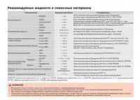
Руководство по эксплуатации и техническому обслуживанию автомобиля SsangYong Rexton второго поколения после рестайлинга.
- Автор: —
- Издательство: SsangYong
- Год издания: —
- Страниц: 363/28
- Формат: PDF
- Размер: 11,7 Mb
Руководство по эксплуатации и техническому обслуживанию автомобиля SsangYong Rexton первого поколения.
- Автор: —
- Издательство: SsangYong
- Год издания: —
- Страниц: 269
- Формат: PDF
- Размер: 5,6 Mb
Руководство по эксплуатации, техническому обслуживанию и ремонту автомобилей SsangYong Rexton/Rexton II с 2002 года выпуска с бензиновыми и дизельными двигателями.
- Автор: —
- Издательство: Третий Рим
- Год издания: 2007
- Страниц: 435
- Формат: DjVu
- Размер: 55,5 Mb
