![]()
Information in this manual is subject to change without notice and does not represent a commitment on the part
of Applied Acoustics Systems DVM Inc. The software described in this manual is furnished under a license
agreement. The software may be used only in accordance of the terms of this license agreement. It is against the law
to copy this software on any medium except as specifically allowed in the license agreement. No part of this
manual may be copied, photocopied, reproduced, translated, distributed or converted to any electronic or
machine-readable form in whole or in part without prior written approval of Applied Acoustics Systems DVM
Inc.
Copyright ©2015 Applied Acoustics Systems DVM Inc. All rights reserved. Printed in Canada.
Program Copyright ©2008-2015 Applied Acoustics Systems, Inc. All right reserved.
Strum GS is a Trademark of Applied Acoustics Systems DVM Inc. Windows and Windows Vista are registered
trademarks of Microsoft Corporation in the United States and other countries. Mac OS and Audio Units are
registered trademarks of Apple Corporation. VST Instruments and ASIO are trademarks of Steinberg Soft Und
Hardware GmbH. RTAS and AAX are registered trademarks of Avid Technology Inc. All other product and
company names are either trademarks or registered trademarks of their respective owner. Unauthorized copying,
renting or lending of the software is strictly prohibited.
Visit Applied Acoustics Systems DVM Inc. on the World Wide Web at
www.applied-acoustics.com
Contents
1 Introduction
1.1 System Requirements
1.2 Installation and Authorization
1.3 Getting Started
1.3.1 Using Strum GS in Standalone Mode
1.3.2 Exploring the Factory Sounds
1.3.3 Using Strum GS as a Plug-in
1.4 Getting Help
1.5 About this Manual
2 An Overview of Strum GS
2.1 Playing Mode
2.2 Chord Detection and Voicing
2.3 Strumming
2.4 Signal Flow
2.5 Interface
2.5.1 The Play View
2.5.2 The Edit View
2.5.3 The Effects View
3 Playing Strum GS-2
3.1 Keyboard Mode
3.1.1 Hammer-On and Pull-Off
3.2 Guitar Mode
3.2.1 Chord Keys
3.2.2 Strumming Keys
3.2.3 Guitar Mode with Auto-Strum
3.2.4 Chord Change
3.3 Loop Mode
3.3.1 Adding Expressivity to Loops
3.3.2 Creating MIDI Loops
3.3.3 Organisation of MIDI Loops on disk
3.4 Chord Voicing
3.5 Specific Techniques
3.5.1 Arpeggios
3.5.2 Trills
3.5.3 Muted Strum
3.5.4 Partial Strumming
3.5.5 Bass & Chords
3.5.6 Stationary Bend
4 Bank and Program Management
4.1 Banks and Programs
4.2 Saving Programs
4.3 The Bank Manager
4.4 Using MIDI Bank and Program Changes
4.5 Backups of Banks and Programs
4.6 Exchanging Banks and Programs
4.7 Restoring the Factory Library
5 Parameters
5.1 General Functioning of the Interface
5.1.1 Knobs
5.1.2 Switches
5.1.3 Drop-down Menus
5.1.4 Modulation Signals
5.1.5 Synchronisation
5.2 The Play View
5.2.1 The Play Mode
5.2.2 Pitch and Modulation Wheel
5.2.3 The Pickups Module
5.2.4 The Clock Module
5.2.5 Strumming
5.2.6 Chord Display
5.2.7 Chord Voicing
5.2.8 Loops Module
5.2.9 Keyboard
5.3 The Edit View
5.3.1 The String Module
5.3.2 The Pick Module
5.3.3 The Hammer-On module
5.3.4 The Mute Module
5.3.5 The Palm Module
5.3.6 The Body Module
5.3.7 The Pickups Module
5.4 The Effects View
5.4.1 EQ
5.4.2 Compressor
5.4.3 Amplifier
5.4.4 Delay
5.4.5 Distortion
5.4.6 Chorus
5.4.7 Flanger
5.4.8 Phaser
5.4.9 Wah
5.4.10 Notch Filter
5.4.11 Reverb
6 Utility Section
6.1 The MIDI LED and MIDI configuration
6.2 Tuning
6.3 History and Compare
6.4 Volume
6.5 Level Meter
6.6 The About Box
7 Audio and MIDI Settings
7.1 Audio Configuration
7.1.1 Selecting an Audio Device
7.1.2 Latency
7.2 MIDI Configuration
7.2.1 Selecting a MIDI Device
7.2.2 Creating MIDI Links
7.2.3 Creating a default MIDI Map
7.2.4 MIDI Program Changes
7.2.5 MIDI Bank Changes
7.2.6 Pitch bend
7.2.7 Aftertouch
7.2.8 Live MIDI Loop Control
7.2.9 Modulation wheel
8 Using Strum GS as a Plug-In
8.1 Audio and MIDI Configuration
8.2 Automation
8.3 Multiple Instances
8.4 Saving Projects
8.5 Performance
9 Appendix — Lists of Chords Detected by Strum GS
10 License Agreement
1 Introduction
Strum GS is a synthesizer dedicated to the emulation of acoustic and electric guitars. The synthesizer is
entirely based on the AAS physical modeling technology and uses no sampling nor wave tables. Instead it
produces sound by solving, on the fly, mathematical equations modeling the different components of a
guitar and how they interact. This elaborate synthesis engine responds dynamically to the control
signals it receives while you play thereby reproducing the richness and responsiveness of real
instruments.
Strum GS features elaborate modeling of the vibrations of the strings, pick or finger action, the body of
the guitar, pickups, a two-channel amplifier, speaker cabinet, spring reverb and various effects. Strum GS
also includes many functionalities which make it easy to reproduce the playing techniques of a guitarist on
a keyboard. Strum GS includes a chord detection module and performs automatic voicing of chords. In
other words, you play the chords you know on the keyboard and Strum GS will voice them automatically,
for different musical styles, as a guitarist would have played them. The picking-hand technique of a
guitarist is reproduced by an auto-strum function, special strumming keys or using standard MIDI
loops.
Before discussing the synthesizer in more detail, we would like to take this opportunity to thank you
for choosing an AAS product. We sincerely hope that this product will bring you inspiration, pleasure and
fulfill your creative needs.
1.1 System Requirements
The following minimum computer configuration is necessary to run Strum GS:
Mac OS
- Mac OS X 10.11 (El Capitan) or later
- Intel Core i5 (circa 2012), Apple M1 processor or later
- 64-bit DAW
Windows
- Windows 10 64-bit or later
- Intel Core i5 (circa 2015) or later
- 64-bit DAW
Keep in mind that the computational power required by Strum GS depends on the number of voices of
polyphony and the sampling rate used. These computer configurations will enable you to play the factory
sounds with a reasonable number of voices but performances will vary depending on your specific
computer configuration.
1.2 Installation and Authorization
Installation and authorization of Strum GS is quick and easy. For the installation of our different products
we use so-called custom installers which include both the program itself and your licence information.
Installation and authorization can therefore be carried out automatically in a single step and from a single
file when your computer is online. AAS products use a a copy protection system based on a a proprietary
challenge/response key exchange and therefore their authorization does not rely on other third party
software and/or hardware.
In order to start the installation process, simply double-click on the installer file that you have
downloaded. This will first install the program and then use the licence information included in the custom
installer file to to carry out automatically the challenge/response procedure.
Once the installation is completed, you can check your licence information by starting the program
and clicking on the chevron icon at the top of the interface. This will open a dialog box in which you
should see your serial number and the email address which you used in order to get the installer
file. Note that your serial number is also sent to you by email when your custom installer is
created.
If your computer is offline when running the installer, or if the authorization procedure could not be
completed for another reason, the dialog box will will not show your serial number and you will be
prompted to authorize the program. In that case, click on the Authorize button and follow
the on-screen instructions. Note that it is possible to use the program during 15 days before
completing the authorization process. After that period, the program will not function unless it is
authorized.
1.3 Getting Started
1.3.1 Using Strum GS in Standalone Mode
Strum GS comes with a standalone versions allowing you to play it without having to open your
sequencer. This can be convenient to explore Strum GS and its library, play it live or do some
sound design work. To start Strum GS in standalone mode, simply follow the instructions
below:
- Windows — Double-click on the Strum GS icon located on your desktop or select Strum GS
from the Start > All Programs > menu. - Mac OS — Double-click on the Strum GS icon located in the Applications folder.
Before you start exploring the program, take a moment to set up you audio and MIDI configuration as
explained below.
Audio and MIDI Configuration
Audio and MIDI configuration tools are available by clicking on the Audio Setup button located in the
lower left corner of the Strum GS interface. The Audio Setup dialog first allows you to select an audio
output device from those available on your computer. Multi-channel interfaces will have their outputs
listed as stereo pairs.
On Windows, the audio output list is organized by driver type. The device type is first selected from
the Audio Device Type drop-down list. If you have ASIO drivers available, these should be selected for
optimum performance. The Configure Audio Device button allows you to open the manufacturer’s setup
program for your audio interface when available.
Once the audio input has been selected, you can then select a sampling rate and a buffer size from
those offered by your audio interface.
The list of available MIDI inputs appears at the bottom of the dialog. Click on the checkbox
corresponding to any of the inputs you wish to use.
1.3.2 Exploring the Factory Sounds
Strum GS comes with a wide range of factory programs right out of the box which amounts to a huge
range of sounds before you have even turned a single knob. As you would expect, the best way of coming
to grips with the possibilities Strum GS offers is simply to go through the programs one at a
time.
Strum GS uses the notions of Banks and Programs to organize and classify sounds. A program or
preset is a stored set of parameters corresponding to a given sound. The programs are grouped and
organized in banks.
The name of the currently loaded bank and program are displayed at the top of the interface. One
navigates among the different banks and programs by using the arrows in each of the corresponding boxes
or by opening the associated drop-down menu by clicking inside these boxes. Banks and programs are
managed using the Bank Manager which is revealed by clicking on the Manage button appearing above
the right-top corner of the Bank box. Playing programs and organizing them is pretty straightforward,
please refer to Chapter 4 for a complete description of the bank and program management
operations.
1.3.3 Using Strum GS as a Plug-in
Strum GS integrates seamlessly into the industry’s most popular multi-track recording and sequencing
environments as a virtual instrument plug-in. Strum GS works as any other plug-in in these environments
so we recommend that you refer to your sequencer documentation in case you have problems running
Strum GS as a plug-in. Note that in plug-in mode the audio and MIDI inputs, sampling rate, and buffer size
are determined by the host sequencer.
1.4 Getting Help
AAS technical support representatives are on hand from Monday to Friday, 9am to 6pm EST. Whether you
have a question on Strum GS, or need a hand getting it up and running as a plug-in in your favorite
sequencer, we are here to help. Contact us by phone or email at:
- North America Toll Free: 1-888-441-8277
- Worldwide: 1-514-871-8100
- Email: support@applied-acoustics.com
Our online support pages contain downloads of the most recent product updates, and answers to
frequently asked questions on all AAS products. The support pages are located at:
1.5 About this Manual
Throughout this manual, the following conventions are used:
- Bold characters are used to name modules, commands and menu names.
- Italic characters are used to name controls on the interface.
- Windows and Mac OS keyboard shortcuts are written as Windows shortcut/Mac OS shortcut.
2 An Overview of Strum GS
Strum GS is a synthesizer which was designed with the goal of enabling keyboard players to easily create
realistic guitar tracks. This is a task which is usually difficult to achieve due to the very different nature of
these two types of instruments. Strum GS was therefore designed to reproduce not only the
sounding mechanisms of a guitar but also the main elements of the playing technique of a guitar
player.
Very generally playing on a guitar can be described in terms of fretting hand (usually left
hand) and picking hand (usually right hand) techniques. The fretting hand is used to fix the
chords or notes played on the different strings of the guitar while the picking hand is used to
set the different strings into vibration and therefore play melodies or strumming patterns. In
Strum GS, these functions have been integrated into a chord detection, voicing, and strumming
module.
2.1 Playing Mode
In practice, Strum GS can be played using one of three available modes: Keyboard, Guitar, or Loop
mode.
In Keyboard mode, Strum GS reproduces what is played on the keyboard as for any other keyboard
instrument without trying to voice what is being played. The range of the instrument is then limited to the
natural range of a guitar as the notes still need to be played on the modeled strings on which Strum GS is
based.
In Guitar mode, Strum GS voices chords played with the fretting hand and reproduces picking hand
technique using special strumming keys as described below.
Loop mode is similar to Guitar mode except that strumming and picking patterns are played from
recorded MIDI files.
2.2 Chord Detection and Voicing
Chords played on a keyboard and a guitar share the same name but are played or voiced differently.
Because of the tuning of the strings on a guitar, the notes of the chord are not usually played in the same
order as on a keyboard and the range of the notes is usually different, notes may also be repeated.
Furthermore, the same chords can be played in different positions on the guitar depending on the playing
or musical style. This specific way of playing chords on a guitar is very characteristic of the
tone and sound of the instrument. It is therefore very important, in order to obtain a realistic
guitar sound, to play chords as a guitar player would rather than how they are played on the
keyboard.
In Guitar or Loop mode, the voicing of chords is performed in two steps by Strum GS. A chord played
on the keyboard is first interpreted by the chord detection module in order to determine which
chord was played on the keyboard. Strum GS then finds a guitar voicing corresponding to this
chord. In other words, Strum GS finds how a guitar player would have played this particular
chord.
When chords are played on the keyboard, the order of the notes above the root is not taken into
account by the chord detection engine. This implies that you can play the chords as you know them on the
keyboard without having to know or learn special voicings used by guitar players. For example, you could
play chords in close position with the left or right hand, you could also play the root with the left hand
and the rest of the chord with the right hand or play the chords with the notes spread across
both hands. Strum GS will take care of finding the right voicing and playing position on the
guitar depending on the settings of the chord type and playing position controls as described in
section 3.4
The name of the chord detected as well as the specific voicing chosen by Strum GS is displayed in the
fretboard located in the lower portion of the graphical interface of the Play view. Note that
the voicing chosen by Strum GS varies depending on the chord type chosen by the user as is
described in Section 3.4. Strum GS will try to detect a chord as soon as three or more keys are
depressed on the keyboard. Please refer to section 9 for a list of the chords detected by Strum
GS.
2.3 Strumming
On a guitar, notes and chords are triggered by the action of the picking hand (usually right hand). The
resulting sound is very typical of a guitar as the guitarist triggers the strings sequentially, more or less
rapidly, with an up and down motion of the hand. Strings can also be played individually, in different
order, to create arpeggio patterns. Different sonorities can be obtained by damping or muting the strings
either by applying the picking hand on the strings near the bridge (palm muting) or releasing the pressure
on the notes played with the fretting hand (scratching) while strumming. Using these different types of
hand motions and techniques, the guitarist can create complex melodic and rhythmic patterns. In Strum
GS, these different effects can be achieved through a strumming module which is controlled by
special strumming keys or MIDI loops as will be explained in more details in Chapter 3 and
5.
2.4 Signal Flow
The general signal flow of Strum GS is presented in Figure 1 and illustrates schematically how the
different modules in Strum GS interact. From left to right, the synthesizer first includes a chord detection
module which parses the MIDI signal it receives and determines the chords played on the keyboard. This
information is then sent to the voicing engine which, taking into account how a guitarist would actually
play the different chords, determines which notes are played on the different strings of the
guitar. The corresponding information, for each of the six strings of the instrument, is then
sent to a triggering or strumming module which generates an excitation signal for each of the
individual string. This is the signal received by the synthesis or string module which then
simulates the vibration signal of the individual strings of the guitar. The output of this module
corresponds to the signal that would actually be measured at the bridge of the instrument and
which is transmitted to the body of the instrument. The body module completes the instruments
and simulates how sound is radiated both from the top-plate of the body (or soundboard) and
the air cavity of the body. Finally, in addition to the modules reproducing the guitar itself, a
multi-effect processor has been included to allow further shaping of the sound radiated by the
instrument. The multi-effect processor comprises an equalizer, a compressor, two effects, and a
reverb.

Figure 1: General signal flow of Strum GS.
It is important to note how the MIDI signal received by the synthesizer is parsed. In Guitar and Loop
mode, signal received from the MIDI input or MIDI player module, is interpreted in terms of the fretting
hand (usually left hand) and picking hand (usually right hand) of a guitar player. MIDI notes with number
ranging between E two octaves below middle C (MIDI note number 40) and C one octave above middle C
(MIDI note number 72) are associated with the fretting hand and their corresponding signal is sent to the
chord detector. Notes in the octave just above (MIDI note number ranging between 72 and 84) are special
strumming keys, used to trigger different picking hand techniques, and are therefore used to
control the strumming engine. The use of these strumming keys is explained in more details in
section 3.2.2.
In the case of the electric guitar, in addition to the instrument itself, the amplifier and cabinet are
fundamental to the production of sound. A two-channel amp, with cabinet and spring reverb has therefore
been added to the signal flow between the two effects of the multi-effect processor as show in
Figure 2.

Figure 2: Position of the amplifier in the signal chain in the case of the electric guitar.
2.5 Interface
The graphical user interface has been organized around three different views as shown in Figures 3, 4, 5,
6, and 7.
The first view, called the Play view of the instrument, is the main view and gives access to different
performance parameters of the guitar. The second and third views, called the Edit and Effects views
respectively, are used for in-depth editing of the synthesis and effect parameters.
One can switch from one view to the other by using the Play, Edit and Effects buttons located
in the Utility section at the top of the interface. This section of the interface is common to
all the views and includes the bank manager, used to access and manage sounds, as well as
general settings and indicators. These tools are described in details in Chapter 4 and Chapter 6
respectively.
The interface for acoustic and electric guitars is different and changed accordingly when selecting an
acoustic or electric guitar preset. While the interface changes when switching from one type of guitar to
the other, the general functioning is similar regardless of the type of guitar used. The main differences
appear in the Play and Edit view. In the Play view the EQ and compressor modules appearing with
acoustic guitars is replaced by an amplifier module in the case of the electric guitar while in the the
Edit view, the body of the acoustic guitar is replaced by a pick-up in the case of the electric
guitar.
The size of the graphical interface can be adjusted by click-dragging the handle in its lower right
corner. While resizing the interface the zoom factor is displayed in the upper left corner of the interface.
This zoom factor can always be displayed by positioning the mouse on this corner. When clicking on the
zoom factor, a drop-down menu with specific size ratios is displayed. Selecting a value resizes the
interface automatically to that ratio. Note that this resize feature is only available for 64-bit versions of the
program.
2.5.1 The Play View
The lower section of this view includes a playing mode selector, a master clock, a chord display, a loop
player as well as as modules controlling strumming and voicing and vibrato which will be described in
more details in Chapter 5.
On the left of these parameters, one finds a pitch bend wheel and a modulation wheel. The modulation
wheel is normally used to control the amount of vibrato in the sound but it can also be used to adjust any
other parameter through MIDI links which will be described in Chapter 7. Just below is a clickable five
octave keyboard giving information on the keyboard layout specific to each playing mode and allowing
one to play different notes which can be useful when no MIDI keyboard is connected to the
computer.
The middle section of this view allows one to turn the effects from the multi-effects module,
compression and equalizer on and off and to rapidly adjust their main parameters.

Figure 3: The Play view for acoustic guitars.

Figure 4: The Play view for electric guitars.
2.5.2 The Edit View
The Edit view gives access to the synthesis parameters described in details in Chapter 5 and allows one to
really go under the hood. In particular pick, individual strings and body parameters can all be adjusted
allowing one to really customize the presets and even create new instruments.

Figure 5: The Edit view.

Figure 6: The Edit view for electric guitars.
2.5.3 The Effects View
The Effects view includes an equalizer, a compressor a multi-effects, and a reverb module. The
multi-effects module consists in two effects in series. The effect list includes a delay, distortion, chorus,
flanger, phaser, wah wah, auto wah and a notch filter. The functioning of the effect modules is described in
details in Chapter 5.

Figure 7: The FX view.
3 Playing Strum GS-2
Strum GS can be played in three different modes: Keyboard, Guitar, or Loop mode. The playing mode is
selected by clicking on the corresponding button in the Play Mode box in the lower left part of the
Play view of the interface. In this chapter, we review how these different modes work and
describe the special keyboard layout each of them uses. We also review the different options
that affect chord voicing in Guitar and Loop mode and discuss how to obtain specific guitar
techniques.
3.1 Keyboard Mode
The Keyboard mode is the simplest way to play Strum GS. In this configuration, Strum GS basically plays
notes on the guitar as they are played on the keyboard. In other words, Strum GS does not attempt to voice
notes or chords played on the keyboard. The main difference with a traditional keyboard instrument is the
range of the instrument. Strum GS indeed needs to play the notes on the different strings of the modeled
guitar so will only react to notes in the normal range of the guitar that is from the second E
below middle C (MIDI note number 40) to the third A above middle C (MIDI note number
93).
The Keyboard mode is the only one that allows one to play melodies and intervals, it is therefore used
for lead guitar playing. It also enables one to play chords without voicing from Strum GS and therefore to
control exactly how they are played.
3.1.1 Hammer-On and Pull-Off
In Keyboard mode, hammer-ons and pull-offs are automatically triggered by playing legato notes spaced
by one or two semi-tones. Hammer-on and pull-off are playing techniques used by guitar players to play
legato or grace notes. The hammer-on effect is obtained by first picking a note and then hammering down
another finger onto the same string at a higher fret. The pull-off effect is almost the opposite of the
hammer on. It is obtained by first picking a note and then sharply pulling-off the finger from
the fretboard in order to hear a second fretted note on the same string. The sounds produced
using these techniques are softer and less percussive than the ones produced by picking the
notes.
3.2 Guitar Mode
In this mode, the MIDI signal received by Strum GS is interpreted in terms of the fretting hand (usually
left hand) and picking hand (usually right hand) of a guitar player. The range of the MIDI keyboard has
therefore been divided into two sections, the Chord keys section and the Strumming Keys section as
illustrated in Figure 8.

Figure 8: Sections of the MIDI keyboard as used by Strum GS in Guitar mode. The C with the
dot is middle C
3.2.1 Chord Keys
This section is associated with the fretting hand of the guitarist and includes notes ranging
from the second E below middle C (MIDI note number 40) to B one octaves above middle C
(MIDI note number 71). This section of the keyboard is where chords are played and it is the
MIDI signal from this section which is sent to the chord detection and voicing modules as
explained in section 2.4. Strum GS will try to detect a chord and find a corresponding voicing as
soon as three or more key are depressed on the keyboard. Note that the exact guitar voicing
chosen by Strum GS depends on the setting of the Voicing module as will be explained in
section 3.4.
Automatic Chords
In Guitar mode, chords are always played by Strum GS when a single note or special configuration of two
or three notes are played in the Chord Keys section of the keyboard making it very easy to create
strumming patterns. When only a single note is played, a major chord is automatically constructed using
this note as the chord root. A minor chord is created by playing a root note and the first black key to its
left. A seventh chord is played by depressing a root note and the first white key to its left. A minor seventh
chord is obtained by playing a root note and the first black and white key to its left. These special rules are
illustrated in Figure 9 with the key of C as an example. Note that other two note intervals are ignored and
a major chord is played using the first note of the interval which was played as the root of the
chord.
Figure 9: Automatic chords. The key of C is used as an example but all keys follow the same
rules.
3.2.2 Strumming Keys
The twelve notes from the C note located one octave above middle C (MIDI note numbers 72 to 83) are
interpreted as special strumming keys and are used to trigger different picking hand techniques. Note that
these special strumming keys appear in a mirror configuration starting on C located three octaves below
middle C allowing one to trigger them with the left hand instead of the right hand. Depending on the
strumming keys used one can trigger downstrokes, upstrokes as well as muffled downstrokes and
upstrokes and palm muted downstrokes. Strings can also be triggered individually to play
arpeggio patterns. The effect of the different strumming keys, illustrated in Figure 10, is now
reviewed.

Figure 10: Strumming keys as used by Strum GS in Guitar mode.
Downstroke and Upstroke
A downstroke is achieved by dragging a pick (or the fingers) across the strings of the guitar in a downward
motion. Notes are therefore played from lowest to highest. An upstroke is obtained in the same manner but
dragging the pick or fingers upwards from the highest to the lowest string. A downstroke is triggered by
depressing C while an upstroke is triggered by depressing D one octave above middle C (MIDI note 72
and 74). These strokes represent the simplest way to play chords on a guitar and can be played alternately.
Note that when strings are not used in a specific voicing (strings with no dot on the chord
display), they are not played when using a downstroke or an upstroke. If no note is played on
the keyboard, the downstroke and upstroke keys trigger a strum but the strings are muted.
The effect is the same as using the muffled down- and upstroke keys which are described
below

Figure 11: Downstroke and upstroke on a C chord with the strumming keys.
Palm Muting
Palm muting is a technique which consists in partially muting the strings with the help of the
picking hand by letting it lightly touch the strings near the bridge. The pick (or fingers) is then
dragged across the strings in a downward or upward motion. In Strum GS, the palm muted
downstroke is obtained by depressing C# one octaves above middle C (MIDI note number
73).

Figure 12: Alternating downstoke and palm muting.
Muffled Downstroke and Upstroke
On a guitar, fretted notes can be muted by decreasing the pressure applied by the fretting fingers on the
strings. The guitarist can control the effect by applying more or less pressure on the strings and obtain a
percussive effect by striking the strings with the picking hand. This effect is also known as
scratching. In Strum GS, the muffled downstroke and upstroke are obtained by depressing F#
and G# one octave above middle C (MIDI note number 78 and 80) respectively. Using these
keys has the same effect as using the down- and upstroke keys without playing a chord on
the keyboard, but these strumming keys allow one to obtain the effect without releasing the
chord.

Figure 13: Scratching with the strumming keys.
Mute All
A muted strum is a stroke which is immediately muted by applying the full hand on all the strings in order
to completely stop the sound. In Strum GS, this is effect is reproduced by depressing B♭ one octave above
middle C (MIDI note number 82).
Playing Individual Strings
The strings of the guitar can be played individually enabling one to arpeggiate or create finger picking
patterns. Individual strings are triggered by depressing notes corresponding to white keys between E one
octave middle C and C two octaves above middle C (MIDI notes 76, 77, 79, 81, 83 and 84, arpeggio keys 6
to 1).
In chords using the six guitar strings, these arpeggio keys (number 6 to 1) correspond to the individual
strings from string 6 (lowest E) to string 1 (highest E). When some voicings use less than six
strings, the arpeggio keys corresponding to the unused strings repeat the note of the following
or preceding string depending if it is the lowest or highest note of the chord. For example
for a chord using strings 5 to 1, the lowest note on string 5 will be repeated on the arpeggio
key 6 (E). For a chord using strings 6 to 2, the highest note of the chord from string 2 will be
repeated on the arpeggio key 1 ( second C in the strumming key section). Exceptionally for
chords played on four strings, string 4 will be repeated on the arpeggio keys 6 and 5 (E and F),
string 1 will be repeated on the arpeggio keys 2 and 1 (B and C) while strings 2 and 3 will be
moved to the arpeggio keys 3 and 4 (G and A). Indeed, this configuration ensures that the
lowest note of the chord will appear on arpeggio key 6 and that arpeggio keys 4, 3, and 2 will
always play a different note which is convenient to play an arpeggio patter in any chord voicing
type.
Alternate Bass
In certain musical styles, such as country and bluegrass, one often finds rhythm-guitar patterns obtained by
switching the root or fifth played on the bass string and a strum on the remaining strings. To easily recreate
these effects, Strum GS maps the fifth or alternate bass on the E♭ key (MIDI note number 75) located one
octave above middle C. When there is no fifth in the chord, the root of the chord is instead mapped to this
key.
3.2.3 Guitar Mode with Auto-Strum
When the Auto-Strum mode is selected, strumming is triggered as notes or chords are played on
the keyboard without having to use the strumming keys. This mode is switched on or off by
clicking on the Auto button in the Strumming section of the interface. In Auto-Strum mode,
chord are strummed using a downstroke or in other words, notes are played from lowest to
highest.
When the Auto-Strum mode is switched off, notes and chords are processed by the chord detection and
voicing modules but the strings are not triggered. In order to play them, one must use the different
strumming keys as described in section 3.2.2. As soon as a strumming key is depressed, the strings are
triggered. Note that strumming keys are always active whether the Auto-Stum mode is switched on or
off.
Strum Down
Play a chord in the Chord Keys section of the keyboard as shown in Figure 14. The chord is detected by
Strum GS and voiced on the guitar fretboard. This triggers a downstroke from the strumming module and
consequently the strings are played from the lowest to the highest. In order to trigger a new downstroke
without muting the strings, just release one note from the chord and play it again as shown in Figure 15.

Figure 14: A simple strumming sequence.
3.2.4 Chord Change

Figure 15: Re-triggering a downstroke.
Once a chord has been played, the chord detection, voicing and strumming modules are only triggered
when a new note or a strumming key is played; releasing notes from a chord has no effect. Consequently,
Strum GS holds the current chord as long as all its notes are not released. This can be used to make rapid
chord changes. For example, it is possible to switch from a C chord to a G chord without muting the
strings by playing C-E-G and then by replacing C and E by B and D without releasing the G as shown in
Figure 16. The same effect can be obtained with chords which do not share common notes by using the
sustain pedal.
![]()
Figure 16: Smooth chord transition.
On the other hand, if one wishes to remove a note from a chord, for example to switch from a C7
chord (C-E-G-B♭) to a C chord (C-E-G), it is not sufficient to release the B♭ key. It is necessary, in order to
trigger again the chord detection module, not only to release the B♭ from the chord but also to depress a
strumming key or to release another note from the chord, for example the G, and replay it when one wants
to strum the new chord.
Chords and Change of Pitch
Playing chords on higher or lower notes on the keyboard does not affect where Strum GS plays them on
the fretboard as it always tries to play chords on a position as low as possible. Strum GS, however, will
take into account the fret position as set by the Position parameter of the Voicing module and
play the chords on this fret or above whenever possible. The only exception to this is when
drop chords are used in which case Strum GS will try to follow chord position as closely as
possible.
3.3 Loop Mode
Reproducing complex strumming patterns can rapidly become complicated and requires to be a good
keyboard player. The good news is, however, that Strum GS is supplied with a library of MIDI
loops which you can use to easily start creating a new piece. A MIDI loop is a recording of
strumming patterns created using the special strumming keys available in Guitar mode as
described in section 3.2. These patterns are automatically applied to chords played on the
keyboard.
In Loop mode, the MIDI keyboard is divided into a Chord Keys section where chords played by the
fretting hands are played and a Loop Keys section, as illustrated in Figure 17, from which MIDI loops
reproducing strumming key patterns are triggered. Note that the automatic voicing of chords in Loop mode
is done in the same was as when playing in Guitar mode.

Figure 17: Sections of the MIDI keyboard as used by Strum GS in Loop mode. The C with the dot
is middle C
Each Strum GS preset is saved with a set of seven loops called a loop pack. The seven white notes in
the Loops Keys section of the keyboard, from C to B located one octave above middle C, are used to
trigger one of the seven loops of a loop packs as shown in Figure 18. The same Loop Keys also appear in
mirror configuration starting on the C key located 3 octaves below middle C. Loop packs can
be loaded from the Loops module from the Play view as will be explained in section 5.2.8.
The currently selected loop is indicated by the purple key in the Loop Keys section of the
keyboard.
Once triggered, loops play until the notes held in the Chord Keys sections are released or
if the B♭ or second C of the Loop Keys section is depressed. The difference between these
two keys is that the B♭, Mute key mutes all strings and the sound stops as soon as the key is
depressed. When the C or Stop key is used, the loop stops but the sound is allowed to decay
naturally.

Figure 18: Strumming keys as used by Strum GS in Loop mode.
3.3.1 Adding Expressivity to Loops
In order to make MIDI loops more expressive, Strum GS allows one to link two different MIDI controllers
to some performance parameters such as playing softer or louder, slower or faster, increase or decrease the
strumming span and putting emphasis on lower or higher strings when strumming. To access this
modulation matrix, open the MIDI configuration window by clicking on the MIDI button located just
below the MIDI led in the top part of the interface and assign effects to controllers in the Live MIDI Loop
Control section of the window.
3.3.2 Creating MIDI Loops
Loops for Strum GS are easily created in your favorite sequencer by respecting the following
rules:
- ∙
-
All the events must be on MIDI channel 1.
- ∙
-
The loop must begin at the start of the file and finish at the end of the track. In other words,
if the track lasts for four bars but there are notes only in the first bar, Strum GS will still loop
over the four bars. - ∙
-
The tempo and the time signature must be defined at the beginning of the loop and must not
change during the rest of the loop. Strum GS indeed ignores tempo changes occurring in the
middle of a loop. - ∙
-
The loop must be recorded on disk on a file using MIDI format 0 or 1 and having a .mid
extension.
Here are other advices which help to create more realistic loops:
- ∙
-
Always slightly vary the velocity of strumming keys in order to get a more lively result.
- ∙
-
If the loop is short, it may be preferable to repeat the same patterns many time with different
velocities for each repetition. - ∙
-
If the loop includes chords, always make sure that they are well quantized and that there is
always a strumming key played at the same time. This will avoid unwanted strokes when the
loop is played while the Auto-Strum mode is switched on. - ∙
-
Avoid using MIDI controllers whose effect can be changed by the user. For example, the
pitch wheel can either be used to create a bend or a slide; the hold pedal can either hold the
current chord or be used to trigger an alternate strum.
3.3.3 Organisation of MIDI Loops on disk
Loops are stored at a specific location on disk:
On Mac OS:
/Library/Application Support/Applied Acoustics Systems/Strum GS-2/MIDI Library
On Windows:
%PROGRAMFILES(X86)%Applied Acoustics SystemsStrum GS-2MIDI Library
Clicking on the Show Files button on the Loops module of the Play view opens a Finder or Explorer
window (on Mac OS X or Windows respectively) at this specific location. Loops are organised into banks
whose name correspond to folder names within the loops folder. These names are those appearing in the
Bank drop-down menu in the Loops module and Loop packs under these categories are stored within these
folders. The seven loops in a pack all share the same name except for the letter associated
with the note (letters A to B) used to trigger a specific loop which is appended to the loop
name.
3.4 Chord Voicing
On the guitar, there are usually many different ways to play the same chord. Each of these positions or
voicing sounds differently and suits different musical styles. The specific voicing chosen by Strum GS for
a chord depends on the Type parameter from the Chord section of the interface. One can choose between
four types of chords:
- ∙
-
Open Chords. These are chords played with a combination of fretted notes and open strings.
These chords are usually played only within the first three frets of the fretboard. Open chords
are easy to play and extensively used when playing folk music. Note that all chords do not
necessarily have an open position on the guitar. - ∙
-
Movable Chords. These chords do not use open strings. As a result they can be moved
along the fretboard of the guitar allowing one to easily play the same voicing in different
tonalities. This type of chords includes barre chords which are obtained by using one finger to
press down multiple strings across the fretboard. Movable chords always use the maximum
possible number of strings and are therefore useful to play arpeggios. Furthermore they allow
one to play the same arpeggio patterns in different keys. - ∙
-
Drop Chords. These are four note chords which allow for fast and subtle movement between
chords. The positions used by Strum GS are based on drop 2 and drop 3 chords. These chords
are obtained by dropping the second or third voice of a chord down one octave. This type of
chord sounds lighter and is extensively used in jazz. - ∙
-
Powerchords A power chord, also known as fifth chord, consists in a note and another one
a fifth above. In other words it is like a triad without the third. Powerchords are extensively
used in rock music especially with highly distorted sounds as including the third usually
results in unpleasant frequency components in the distorted sound. They are also easy to
play. In powerchord mode, any chord played on the keyboard which contains a natural fifth
will be played with 3 notes: the root, the fifth and the octave. If the chord is inverted on its
fifth, the power chord played by Strum is also inverted and the notes played in the following
order: fifth, root and octave. Note that it is also always possible to play powerchords with the
other chord types by playing a fifth, root and fifth’s octave.
In addition to these voicing categories, the voicing can be made more precise by specifying what
should be the lowest note of the chord played by Strum GS:
- ∙
-
Lowest. The lowest note in the guitar voicing chosen by Strum GS is the lowest note
played on the keyboard. This type of voicing is useful if it is necessary that the bass of the
chord sequence follows a specific movement. Note that for open and movable chords many
inversions do not have an interesting voicing on the guitar and in this case, the four note
voicing generated by Strum GS may sound a bit out of place in a chord progression. - ∙
-
Root. The lowest note in the guitar voicing chosen by Strum GS is the root of the detected
chord. It is very common for guitar chords to have the root in bass position. This choice of
chord type allows one to play chords on the keyboard using any voicing and still obtain a
guitar chord in root position.
The Playing Position parameter from the Chord section allows one to specify the lowest fret on which
the lowest note of a chord should be played. This control gives Strum GS an indication of the position on
the neck where chords should be played and chords are voiced accordingly when possible. This parameter
is of course only valid for movable chords and it is therefore inactive when open chords are
chosen.
Note that in all chord voicing one finds a fifth even if it was not played on the keyboard which in
practice corresponds to what guitar player do. The only exception is for drop chords where
only notes played on the keyboard are used in the voicing and therefore may not contain a
fifth.
Although there is no general rule and there are many ways to play in different musical styles or obtain
different effects, we give some guidelines on chord types and performance settings which should work
well in specific situations:
- ∙
-
Folk. Open-Root and medium strumming speed.
- ∙
-
Country and Bluegrass. Open-Root with a high strumming speed.
- ∙
-
Pop-Rock. Movable-Root.
- ∙
-
Arpeggios with bass motion. Movable-Lowest or Open-Lowest.
- ∙
-
Jazz. Drop chords.
- ∙
-
Samba Bossa. Drop chords. Use the arp 6 strumming key to play the bass and arp keys 4, 3
and 2 simultaneously to play the rest of the chord. - ∙
-
Funk. Movable-Root with Playing Position on a high fret.
- ∙
-
Flamenco Open-Root with a rapid strumming speed. Use the alternate strum on the four
highest strings.
3.5 Specific Techniques
We now look at ways to create more elaborate effects. For these examples, it is assumed that we are using
the Guitar mode and that the Auto-Strum mode is switched off as we will now be using the strumming
keys. This way of playing Strum GS involves to think more in terms of a guitar player and it is preferable
to play the chords slightly before triggering the strumming action in order to avoid glitches when a
strumming key is used before a chord is fully formed on the keyboard . This is just like a guitar player
who needs to position the fretting hand on the fretboard before strumming with the picking
hand.
3.5.1 Arpeggios
A chord can be arpeggiated using the arpeggio strumming keys (E, F, G, A, B and C). The effect of these
keys depends on the chord played by Strum GS as explained in section 3.2.2. As many chords include
only four strings (a bass and three high notes) it is common for the arpeggio 2 and arpeggio 1 keys to play
the same note. Furthermore, depending on the position of the chord on the fretboard, the alternate
bass key (arpeggio 5 key), can play a lower, higher or the same note as the bass key (arpeggio
6 key). The most useful arpeggio keys are therefore usually the arpeggio 6, 4, 3 and 2 keys
(E, G, A and B). A good position to play arpeggios is to use the thumb to play the bass, the
index to play the arp 4 key, the middle finger for the arp 3 key, the ring finger for the arp 2
key and finally the little finger for the arp 1 key. This position is similar to that of a guitar
player.
Here is a simple example of an arpeggio. Play a C chord (C-E-G) with the left hand, and then use the
right hand to trigger the Bass (E), arp 4 (G), arp 3 (A) and arp 2 (B) keys.

Figure 19: A simple arpeggio.
When playing arpeggios, it might be interesting to use Movable-Lowest chord types in order to obtain
a motion of the bass. To try this, set the Type from the Chord section to Movable-Lowest and play the
arpeggio from the preceding example using the following chord progression: C (C-E-G), CMaj7/B
(B-C-E-G), C7/B♭ (B♭-C-E-G) and Am7 (A-C-E-G).

Figure 20: Bass motion and arpeggios.
3.5.2 Trills
This technique consists in switching rapidly between two notes by using hammer-ons and
pull-offs. Trills are available in Keyboard mode and are obtained by holding the first note and
depressing and releasing the second note. The interval between the notes must be one or two
semi-tones.
3.5.3 Muted Strum
A muted strum is a stroke which is muted immediately after having been played by applying the full hand
on the strings. It is less dry than a scratch (muffled stroke) and brighter than a palm muted stroke. One way
to recreate this effect is to strum a chord using the down- and upstroke keys (C or D) and playing the mute
all key (B♭) very rapidly.
3.5.4 Partial Strumming
A guitarist does not always strum all the strings in a chord and they also often vary the number of strings
played between strumming strokes. To some extent, in Guitar mode, this is taken into account
automatically by Strum GS using the MIDI velocity signal received from the keyboard. More control on
this parameter, however, may be desired. One way to control exactly the number of strings that are
strummed is to use the Arpeggio keys instead of the Downstroke and Upstroke keys. In other words, one
strums a chord by depressing a certain number the Arpeggio keys together thereby controlling
which strings are played in the chord. This can also be used to put emphasis certain strings
and and also to introduce some variety and expression in the strumming. Another option is
to alternate between this technique and the use of the downstroke and upstroke strumming
keys.
Another technique which can be used to obtain partial strums consists in releasing strumming keys
before the strum is completed. In this way, the strings still not strummed, are not played. In other words,
partial strumming is achieved by playing staccato on the strumming keys while full strums are obtained by
playing them normally. This technique is easier to perform when the strumming speed is relatively
slow.
When using loops it is possible to vary in real-time the character of the strumming by mapping specific
MIDI controllers to the strumming span and to the weight of low and high strings as explained in
section 3.3.
3.5.5 Bass & Chords
In certain musical styles, such as country and bluegrass music, one often finds rhythm-guitar patterns
obtained by switching between the root or fifth played on the bass string and a strum on the remaining
strings. To obtain this effect, it is therefore important that the lowest string is note included in the stroked
part of the pattern. In order to reproduce this effect with Strum GS, one must first use the bass or alternate
bass key (E or E♭) and hold it while playing one of the stroke triggers. Indeed, when Strum GS detects that
a stroke key is played while the bass or alternate bass key is depressed, it removes this string from the
strum.

Figure 21: Bass and Chord.
3.5.6 Stationary Bend
In this technique, the guitarists plays two notes simultaneously and bends one of the two notes. It is
possible to obtain the effect with Strum GS by taking advantage of the fact that only the last note played is
bent.
In Keyboard mode, one first plays the note which should not be bent and then the second one. The
bending effect is then obtained by moving the pitch wheel or using the aftertouch. This will
only work, however, for intervals larger than one tone because otherwise Strum GS always
automatically triggers a hammer-on or pull-off when intervals of one or two semi-tones are played
legato.
In Guitar mode, the last string triggered with an arpeggio key can be bent either by using aftertouch or
pitch wheel.
4 Bank and Program Management
Strum GS comes with several factory presets, called programs, covering a wide range of sounds. This
collection of programs lets you play and familiarize yourself with this synthesizer without having to tweak
a single knob. Soon, however, you will be experimenting and creating your own sounds and projects that
you will need to archive or exchange with other users. In this section, we review the management of
programs.
4.1 Banks and Programs
Sounds are stored in banks contaning so-called programs. The name of the currently selected bank
is shown in the Bank drop-down display located at the top of the Strum GS interface. The
list of available banks is viewed by clicking on the Bank display. A bank can be selected by
navigating in the list of banks using the left and right-pointing arrows in the display or by
clicking on its name when the list of banks is open. Clicking on the bank display brings focus on
this section of the interface, the display is then outlined by an orange line, and one can then
navigate through the list of banks using the up, down, left, or right arrows of the computer
keyboard.
The list of programs included in the currently selected bank can be viewed by clicking on the Program
display located below the Bank display. A program is selected by using the left and right-pointing
arrows or by clicking directly on its name. Once a program is selected, the value of the different
parameters of the synthesizer are updated and it can then be played. As for the bank list, one can
navigate through the program list using the computer arrows after clicking on the Program
display.
4.2 Saving Programs
Programs are saved by clicking on the Save button located on the top of the Program display. When a
program has just been loaded, this command is greyed and therefore inactive. It is activated as soon as a
parameter of the interface is modified. Clicking on this command replaces the stored version of the
program with the new one.
The Save As command is activated by clicking on the corresponding button which opens the Save
Program pop-up window. It is then possible to save the program under a new name or its current one in
any of the available program banks. Note that if the original name of the program is used, a new program
with the same name will be created at the end of the program list meaning that the original program is not
erased. This also implies that it is possible to have many programs with the same name in the same
bank.
4.3 The Bank Manager
Banks and Programs can be edited using the Bank Manager. The manager window is displayed by
clicking on the Manager button located above the Bank display. It is closed by clicking again on the same
button. On the left of the window, one finds the list of banks. Clicking on a bank name fills the list of
programs located in the center of the window with the name of these included in the selected
bank.

Figure 22: Bank and program manager window.
A new bank can be created by clicking on the + button below the bank list. This opens the
Create New Bank window in which the name of the new bank can be entered. A bank can be
deleted by first selecting it in the bank list and then clicking on the — button. Be careful, this
command erases a bank and all the programs it contains; this operation is permanent and can not
be undone. In order to rename a bank, simply click on the Rename button and enter a new
name.
Banks and the information corresponding to each of its programs is stored in a simple text file on your
computer hard disk. In order to view these bank files, click on the Show Files button under the bank list.
On Windows, this command will open an Explorer window at the location where the files are stored. On
Mac OSX, the command has a similar effect and opens a Finder window. All the bank file names follow
the same format and begin with the bank name. These files can be used for backups or to exchange presets
with other users.
The list of programs included in the selected bank is displayed in the program list in the center of the
manager window. Presets are selected by clicking on their name which updates the program
information appearing on the right of the preset list. Program information includes the name
of the preset, its author and comments. This information can be updated by clicking on the
corresponding box which opens an edition window. Note that multiple presets can be updated
simultaneously by selecting more than one preset at once and clicking on a preset information
box.
A multiple selection consisting of adjacent programs is obtained by holding down the Shift key on the
computer keyboard and then clicking on the name of the first program to be copied and then the last one. A
non-adjacent multiple selection is obtained by holding down the Ctrl/command computer
key and clicking on the name of the different programs to be copied. It is also possible to
select all programs at once by clicking on the Select All button at the bottom of the program
list.
Programs can be copied to another bank by clicking on the Copy button. A program must first be
selected by clicking on its name on the program list; it is then copied by moving the mouse to a
given bank in the Bank list on the right and clicking on the bank name. The Move command is
activated by clicking on the Move button; it copies a preset to a new bank but also erases it in
the original bank. A multiple selection of programs can be used with the Copy and Move
commands
Programs can be deleted from a bank by first selecting them and then clicking on the Delete button.
This will move the programs to a special bank called Trash which is located below the regular list of
banks. This means that deleted programs can always be recuperated as long as they are not deleted from
the Trash bank. The content of the Trash bank is viewed by clicking on its name; the different programs
can then be moved to the other banks as explained above. The Trash bank can be emptied by clicking on
the Empty Trash button which appears below the program list when the Trash bank is selected. Be careful
as this command can not be undone.
4.4 Using MIDI Bank and Program Changes
Banks and programs can be changed using MIDI bank and program change commands. For more
information on how to use these commands, please refer to sections 7.2.4 and 7.2.5.
4.5 Backups of Banks and Programs
User banks are stored on disk as simple text files located in the following folders:
On Mac OS:
/Users/[user name]/Library/Application Support/Applied Acoustics Systems/Strum GS-2/Banks
On Windows:
%AppData%Applied Acoustics SystemsStrum GS-2Banks
The bank files saved by Strum GS are named using the following convention:
[name of bank].GS-2 Bank
These file contain all the information corresponding to the programs they include. These files can be
displayed directly from Strum GS by opening the Bank manager and clicking on the Show Files button.
This will open an Explorer or Finder window on Windows or Mac OS respectively at the right
location.
The simplest way to create a backup of banks and programs is to make a copy on an external media of
the above mentioned folders. Individual banks can be backed-up by making copies of individual bank
files.
4.6 Exchanging Banks and Programs
Banks and programs can easily be shared with other Strum GS users. This operation simply involves the
exchange of the above mentioned user bank files. When a new bank file is copied to the bank folder, it is
automatically available to Strum GS.
Note that individual programs can not be exported. They always appear inside a bank file. If you only
wish to share a few programs, create a new bank, copy the programs you wish to exchange to this bank
and share the corresponding bank file.
4.7 Restoring the Factory Library
If necessary, it is possible to restore the original factory library of banks and programs. The original
factory bank files are located in the following folders:
On Mac OS startup disk:
/Library/Application Support/Applied Acoustics Systems/Strum GS-2/Factory Library
On Windows 64-bit:
C:Program Files (x86)Applied Acoustics SystemsStrum GS-2Factory Library
On Windows 32-bit:
C:Program FilesApplied Acoustics SystemsStrum GS-2Factory Library
Restoring the factory library simply involves copying the files contained in these folders and pasting
them in the user bank folders listed in Section 4.5. The user bank folders can be opened directly in an
Explorer or Finder window, on Windows and Mac OS respectively, or by using the Show Files command
directly from the Strum GS bank manager.
Note that if you have bank files with the original factory bank names in your user bank folder, they will
be replaced by the original factory files. This means that you will lose programs that you would have
modified or created in these banks. This operation must therefore be done with caution and it is
recommended that you make copies or rename your user banks before proceeding with the
restore.
5 Parameters
This section can be used as a reference for the different controls appearing on the Strum GS graphical
interface. We begin by describing the behavior of the different types of controls appearing
on the interface and then describe the parameters of each module of the synthesizer. Note
that the interface of acoustic and electric guitar presets is different. All modules are shared
between guitar types except for the Body module which only appears with an acoustic guitar
preset is selected and the Pickups and Amplifier modules which appear with electric guitar
presets.
5.1 General Functioning of the Interface
5.1.1 Knobs
The synthesizer parameters are adjusted using controls such as knobs, switches and numerical
displays. A specific control is selected by clicking on it. A coarse adjustment is obtained by
click-holding the parameter and moving the mouse, or the finger on a track pad, either upwards
and downwards or leftwards and rightwards. The value of the parameter replaces its label
while it is being adjusted. Double clicking on a knob brings it back to its default value when
available.
Fine adjustment of a control is obtained by holding down a modifier key of the computer keyboard
(Shift, Ctrl, Command or Alt key) while adjusting the parameter. Note that there is one exception
to this in the Strings module where pressing the Ctrl key on Windows or Command key on
Mac OS and turning a knob sets the value for all strings at once. Precise values can also be
entered manually by clicking on the parameter label and typing the value on the computer
keyboard.
5.1.2 Switches
Switches are turned on or off by clicking on them. They are used to activate or deactivate modules and the
sync feature of some parameters.
5.1.3 Drop-down Menus
Some displays reveal a drop-down menu when clicking on them. Adjustment of the control is obtained by
clicking on a selection.
5.1.4 Modulation Signals
The Velocity modulation knobs are used to modulate the value of a parameter depending on the
velocity signal received from the keyboard so that the value of a parameter increases as notes
are played harder on the keyboard. The position of the knob is used to adjust the amount of
modulation applied to the parameter. In its leftmost position, the modulation source is turned
off and the value of the parameter does not vary with the velocity signal from the keyboard.
Turning the knob clockwise increases the effect of the modulation signal on the value of the
parameter.
5.1.5 Synchronisation
The rate of certain effect modules and the tempo of loops can be synchronized to the clock of a host
sequencer or controlled using the built-in Clock module. In order to synchronize effect modules, their
Sync must be turned on. Synchronization values for effects are adjusted with the Sync Rate parameter and
range from 4 whole notes (16 quarter notes) to a thirty-second note (1/8 of a quarter note) where the
duration of the whole note is determined by the host sequencer clock. The effect can also be synced to a
triplet or dotted note. To adjust this parameter, click on the Sync Rate button and choose a rate value from
the drop-down menu.
In standalone mode, the master clock is that from the Clock module on the Play view and the duration
of a whole note is adjusted using the Rate control of the Clock module or the Tap Tempo pad. In plug-in
mode, the master clock is that of the sequencer when the Sync to Host button is switched On. When it
is in its off position, the tempo is controlled by the internal Clock module using the Rate
control.
5.2 The Play View
The Play view is where the main performance oriented modules are located. Key parameters from the
Effects view are also included for quick access. This view is loaded when starting the instrument
and can be accessed from another view by clicking on the Play button on the top part of the
interface.
The middle section of this view allows one to switch on and off the EQ, Compressor and Reverb as
well as the active effect modules. Key effect parameters are also adjustable as presented in the description
of the different effect modules in section 5.4

Figure 23: Middle part of the Play view for acoustic guitars.

Figure 24: Middle part of the Play view for electric guitars.
5.2.1 The Play Mode

The Play Mode module allows one to switch between three playing modes: Keyboard, Guitar and
Loop mode. In Keyboard mode, Strum GS plays notes as they are played on the keyboard without trying to
voice chords. It is mainly used to play leads and to exactly control the voicing of chords. In Guitar mode,
Strum GS plays in terms of a fretting and picking hand as a guitar player would. Chords played on the
keyboard are automatically voiced by Strum GS and special strumming keys are used to strum chords and
play individual strings. The Loop mode is similar to the Guitar mode except that the strumming key
patterns are played from recorded MIDI files. For more information on the specific keyboard
layout and playing techniques for each of these modes, please refer to sections 3.1, 3.2 and
3.3.
5.2.2 Pitch and Modulation Wheel

The MIDI pitch wheel allows one to vary the pitch of the note played. The pitch wheel can be moved
with the mouse but it is also automatically connected to the pitch wheel signal received from your MIDI
keyboard. The range of the pitch bend is 2 semi-tones up or down by default but can be changed. To adjust
the range of the pitch bend, open the MIDI configuration window by clicking on the MIDI
button located just below the MIDI led in the top part of the interface and use the Pitch Bend
Range drop-down menu to select the range in semi-tones. Note that pitch bend also includes a
Slide option. When this option is selected, pitch changes will occur in a discrete manner by
semi-tone steps in order to reproduce the effect of a fretting hand finger going over the frets of the
fretboard.

The modulation wheel is used to control vibrato. It can be activated on screen or from the modulation
wheel of your MIDI controller (MIDI controller number 1). Other parameters can be linked to the
modulation wheel using MIDI links as explained in Section 7.2.2. The amount of vibrato in the sound is
adjusted using the Depth parameter of the Mod Wheel module while its speed is controlled using the
Speed knob.
5.2.3 The Pickups Module

The Pickups module simulates the action of the pickups on the guitar. There are two pickups in Strum,
labeled Neck and Bridge, which can be adjusted in various ways in order to obtain tonal colors of
different guitar types. The switch on the Play view allows one to listen to the signal from the
neck or bridge pickup individually or a mix of both signals when the switch is in its middle
position.
5.2.4 The Clock Module

This module is used to control the tempo of certain effects of the Effects section and loops. In order to
synchronize effects, their sync button must be switched on.
When using Strum GS in standalone mode, the clock tempo, in bpm, is set by using the Rate
knob. The tempo can also be adjusted by clicking at the desired tempo on the Tap Tempo pad
of the module. Once the new tempo is detected, the value of the Rate knob is automatically
adjusted. Note that double-clicking on the Rate sets the tempo to that of the currently loop
pack.
In plugin mode, the Tap Tempo pad is replaced by a Sync To Host button. When this button is turned
on, the rate of effects and loops is synchronized with the clock the host sequencer. When switched off, the
tempo is determined by the value of the Rate knob.
5.2.5 Strumming

The Strumming module includes parameters which determine how the strumming is performed. The
Speed parameter controls how rapidly the different strings are played when a strum is triggered. The speed
of the strum is increased by turning the knob clockwise. This parameter can be modulated by the
keyboard velocity using the Velocity knob. In its leftmost position, the speed is always that
corresponding to the value of the Speed knob. Turning the velocity knob clockwise increases the
strumming speed for high keyboard velocities while it reduces the speed for low keyboard
velocities.
The Auto button is used to switch on or off the Auto-Strum option. It is only active when Strum GS is
played in Guitar mode. When auto-strumming is on, chords are triggered with a downstroke as
soon as one or more keys is depressed in the Chord Keys section. In other words, chords are
played without having to use the special strumming keys. When the Auto-Strum option is turned
off, chords are still recognized and voiced by Strum GS but the strings are not triggered until
strumming keys are used. For more details on how to use the strumming keys, please refer to
section 3.2.2.
5.2.6 Chord Display

The Chord Display is where Strum GS displays the name of the detected chord or note and the
corresponding voicing selected. Strings are labeled from lowest to highest as follows:
- ∙
-
String 6: E (second E below middle C, MIDI note number 40)
- ∙
-
String 5: A (second A below middle C, MIDI note number 45)
- ∙
-
String 4: D (first D below middle C, MIDI note number 50)
- ∙
-
String 3: G (first G below midle C, MIDI note number 55)
- ∙
-
String 2: B (first B belwo middle C, MIDI note number 59)
- ∙
-
String 1: E (first E above middle C, MIDI note number 64)
Notes played are identified by a circle on the corresponding string and the position on the fretboard is
determined by the fret number appearing in the upper left corner of the display. When a string is triggered,
its number is highlighted at the bottom of the display while it vibrates. For a list of all the chords detected
by Strum GS, please refer to section 9.
The name of the detected chord is displayed at the top of the displayed. When the chord contains no
third or no fifth the corresponding no 3 or no 5 message is highlighted. While Strum GS can recognize a
great variety of chords and find most voicings used by guitar players, it is possible that it will not find a
voicing in its chord database for a particular chord played on the keyboard. In these cases, the no
match message is lit. In this case, Strum GS will not display a chord name but still propose a
guitar voicing constructed according to a certain set of rules. The chord should still sound
right but the message is displayed in order to indicate that the voicing chosen by Strum GS is
probably very difficult to play on the guitar and might therefore not be commonly used by guitar
players.
5.2.7 Chord Voicing

On the guitar, chords can be voiced in many different ways. The specific voicing chosen by
Strum GS for a chord depends on the Type parameter. One can choose between open, movable,
powerchords, and drop chords. For more information on the effect of these different chord
types please refer to section 3.4. The voicing can be made more precise by using the Position
parameter which instructs Strum GS on which neck position the chords should be played. The
position is specified in fret number and indicates the lowest fret on which the lowest note of
the chord should be played. It is not always possible to satisfy this constraint and Strum GS
will respect this position whenever it is possible. This parameter is only valid for movable
and drop chords as well as powerchords and it is therefore inactive when open chords are
chosen.
5.2.8 Loops Module

The Loops module is used to play Strum GS with MIDI loops and it is only active when the Loop
mode is selected. Loops contain strumming key patterns that are applied over the chords that are played in
the Chord Keys section of the keyboard.
Strum GS presets are saved with packs of seven loops which are triggered using the white keys from
the Loop Keys section of the keyboard as described in section 3.3. Loop packs are grouped into banks
which can be browsed using the Bank drop-down menu. Individual packs in a bank are selected using the
Pack drop-down menu. Selecting a pack automatically loads the seven loops included in a pack and maps
them to the white keys of the Loop Keys section of the keyboard. A specific loop is selected
and triggered by depressing one of these keys. The intended tempo of the loops in BPM, its
time signature, and information on location within the loop appear just below the loop pack
name.
Clicking on the Show Files button opens a Finder or Explorer window (on Mac OS X or Windows
respectively) at the location where the MIDI looop files are stored. Banks correspond to folder names and
loop packs under these categories are stored in these folders. Loops in a pack all share the same name
except for the note (letters A to B) used to trigger a specific loop which is appended the loop
name.
Once a loop is triggered, it is played at the tempo set by the Clock module or that of the host sequencer
as explained in section 5.2.4. The tempo of the loop can be halved or doubled by using one of the Tempo
buttons located below the pack name. Once triggered, loops play until the notes held in the Chord Keys
sections are released or if the B♭ or second C of the Loop Keys section is depressed. The difference
between these two keys is that the B♭, Mute key mutes all strings and the sound stops as soon as the key is
depressed. When the C or Stop key is used, the loop stops but the sound is allowed to decay
naturally.
Loops can easily be dragged and dropped unto a sequencer track, the computer desktop or a specific
folder by using the MIDI Drag control located below the Loops module. Click holding anywhere on this
control selects the loop currently being played (the one corresponding to the purple key in the Loop Keys
section) allowing to drag it where desired. Note that once a loop is copied onto a track, Strum GS should
be used in Guitar mode for playback so that the keyswitch pattern that was copied is played
correctly. For more information and tips on how to use and edit loops in a project, please refer to
section 3.3.
5.2.9 Keyboard
The lower part of this view includes a keyboard covering five octaves. The specific layout of this keyboard
depends on the playing mode selected allowing one to easily see how the keyboard is mapped in each
mode as described in chapter 3. In Guitar and Loop mode, more information on the effect of individual
notes can be obtained by clicking on the question mark appearing in the end sections of the keyboard.
Clicking on the individual notes of this keyboard has the same effect as depressing the same note on an
external MIDI keyboard. This can be useful to test Strum GS when no MIDI keyboard is connected to your
computer.
5.3 The Edit View
This mode allows one to view and adjust all the parameters used by the synthesis engine. While for most
applications, simply using the presets will be sufficient, one might want in certain cases to access the
different instrument parameters and control them precisely. It can also be a lot of fun to explore the effect
of the different parameters and create your own guitars.
5.3.1 The String Module
The parameters of each of the six strings of the guitar can be adjusted independently. Strings are numbered
from 6 to 1 with 6 being the lowest string (second E below middle C, MIDI note number 40) and 1 being
the highest one (first E above middle C, MIDI note number 64). Clicking on the tabs with
different string numbers on the left of the module reveals parameters for this specific string.
Note also that parameters of a given string can be copied from one to another by clicking on
the down-pointing arrow located to the right of the string number at the top of the module.
Multiple strings can also be adjusted at once by interpolating parameters between the strings.
This can usually be a good starting point when trying new configurations. It is also interesting
to know that the value of a parameter can be adjusted for all the strings at once by clicking
on the Ctrl key on Windows or Command key on Mac OS and adjusting the corresponding
knob.
The vibrational motion of a string can be decomposed into two different components, one
perpendicular to the plane of the body of the guitar and the other one parallel to that plane. At the bridge,
the string is fixed and energy is transferred to the body of the guitar but also exchanged between these
two components of the string motion. This exchange is responsible for both the characteristic
beating effect present in the sound of the guitar and the typical decay curve or envelope of
the sound. Both these motion components are modeled in Strum GS and they are referred to
as motion component H (horizontal — parallel component) and V (vertical — perpendicular
component).

For each motion component, one can adjust three parameters called Decay, Tone and Inharm. The
Coupling knob is used to adjust the amount of energy exchanged between the two polarities of the string
motion. Turning this knob clockwise increases the coupling and therefore the amount and frequency of the
beating in the sound. When in its zero position, there is no coupling between the two motion components.
Both exist but are completely independent of each other resulting in a sound with no beating and a regular
decay envelope. The Balance knob is used to control the mix between both components in the output
sound. In its leftmost position, one only hears component V while in its rightmost position only
component H is heard. In its middle position, an equal mix of both is heard. In general, to get
the most realistic realistic sound, the knob should be turned toward the left or in other words
one should listen more to component V. This is because in a real guitar, vibrational motion
perpendicular to the body is more efficiently transmitted. Interesting effects can however be
obtained by mixing both motion components. Note that even when the balance knob is fully
turned to the left, coupling between both components is still taken into account as soon as the
Coupling knob is turned to the left which will introduce beating in the sound of component
V.
In a real string, the material of the string affects how it vibrates. For example, a metal string oscillates
for a longer time than a nylon one; its sound also contains more high frequencies and is brighter. This
behavior is adjusted with the Tone and Decay knobs. The Tone knobs are used to set the respective amount
of high frequencies in components V or H of the string motion with respect to low frequencies. In their
zero position, the decay time of high frequencies in the sound is lower than that of low frequencies;
turning them clockwise makes it longer. The overall decay time of the vibrations is controlled with
the help of the Decay knobs and it is increased by turning the knobs towards higher values.
As a rule of thumb a nylon string is obtained by setting the Tone knobs to a low value and
using a low decay time. Increasing the value of this two parameters results in a more metallic
sound.
In a first approximation, the strings of a guitar can be considered to be harmonic meaning that their
partials are located at frequencies equal to multiples of the fundamental frequency. Real strings, however,
are more or less inharmonic depending on the homogeneity of the strings along their length. This
characteristic of strings is adjusted, for components V and H, with the Inharm knobs. When these
knobs are in their zero position, the string vibration is perfectly harmonic. Turning the knobs
clockwise increasingly detunes the partials toward higher frequencies resulting in a more dissonant
sound.
5.3.2 The Pick Module
The Pick module allows one to control the parameters related with the excitation of the string. It can
simulate the excitation of the string with a pick or with a finger. Three different pick or plectrum models
are implemented in Strum GS as shown in Figure 25, 26 and 27 each of them corresponding to a
different plectrum profile. The first two models are better to simulate the interaction of the
string with a hard pick while the third one is better to simulate the interaction with a smoother
object such as a smooth pick or a finger. The plectrum model is chosen using the Type selector.

Figure 25: First pick model

Figure 26: Second pick model

Figure 27: Third pick model

The excitation force produced by the plectrum when interacting with the string is determined by
the Depth, Speed, Stiffness and Damping parameters. The Stiffness and Damping parameters
determine the flexibility of the plectrum or in other words the resistance it exerts against the string.
Increasing the value of these parameters will mainly increase the amplitude of the sound.
The Stiffness parameter is used to control the stiffness of the plectrum used. Increasing this
parameter, by turning the knob clockwise, results in thicker or stiffer plectrum. The Damping
parameter controls the amount of damping in the plectrum. The parameter is mainly effective
during the attack of notes. Raising its value, by turning the Damping knob clockwise, results
in additional impact noise when the plectrum first comes into contact with the string when
attacking a note. These two parameters are modulated with the note velocity trough the use of the
Velocity knob below them. When the knob is in its leftmost position, there is no modulation
from the MIDI note velocity; turning this knob clockwise gradually increases the amount of
modulation.
The Depth parameter enables one to control the distance between the edge of the plectrum and the
string when they come into contact. In other words it simulates how far behind the string, a guitar player
introduces the plectrum before picking the string. This parameter affects the loudness and the spectral
content of the sound as well as the the interaction time between the plectrum and the string. The Speed
knob is used to control the speed of the plectrum relatively to the string. The main effect of
this parameter is to determine the interaction time between the plectrum and the string. This
parameter can also be modulated with the MIDI note velocity signal using the Velocity knob
below.
The Edge parameter is used to determine the sharpness of the edge of the pick. It is used to fine-tune
the profiles of the three different plectrum models which affects the shape of the force signal exerted by
the plectrum on the string and therefore the tone of the resulting sound. Turning this knob
towards higher values makes the pick sharper with more high frequencies in the tone. Finally, the
Position knob is used to control the position of the interaction point of the plectrum along the
string. This is a parameter currently used by guitar players to change the tone of the sound.
In its zero position, the pick is very close to the bridge resulting in a more metallic sound.
Turning the knob toward higher values moves the pick toward the fretboard resulting in a rounder
sound.
5.3.3 The Hammer-On module

The Hammer-On module is used to control hammer-on et pull-off. Hammer-on and pull-off are
playing techniques used by guitar players to play legato or grace notes. The hammer-on effect is obtained
by first picking a note and then hammering down another finger onto the same string at a higher fret. The
pull-off effect is almost the opposite of the hammer on. It is obtained by first picking a note and then
sharply pulling-off the finger from the fretboard in order to hear a second fretted note on the same string.
The sounds produced using these techniques are softer and less percussive than the ones produced by
picking the notes.
In Strum GS, hammer-ons and pull-offs are triggered when playing in Keyboard mode and when legato
playing is detected. The two parameters of this module are Amp and Tone. The Tone knob is used to set the
harmonic content of the excitation produced by the finger moving on the string as explained above.
Turning this knob to the left results in a smoother sound while turning it clockwise results in a sharper
sound. The Amp parameter controls the amplitude of the excitation generated by hammer-ons and
pull-offs.
5.3.4 The Mute Module

In Strum GS, strings are muted when the keys forming a chord are released, when a muffled down/up
is used (F♯, G♯ strumming key in Guitar mode or when the mute strumming key (A♯) is depressed in
Guitar or Loop mode. This reproduces the muting effect obtained by guitarists when releasing the pressure
on the notes held by the fretting hand. The pressure applied on a given string is controlled
using the Contact knob. In its leftmost position, the contact is very light and one can slightly
hear the sound of the open string. When this knob is in its rightmost position, the pressure
between the finger and the string is strong and one can hear the pitch of the fretted note. In
its middle position, the string is muted efficiently and one can, depending on the fret where
the finger is located, hear harmonics ringing. The tone and decay time of these harmonics
are set using the Tone and Decay knobs which fix the decay time and the spectral content
of these tones respectively. When muting a string it takes a little time for the guitar player
to release the pressure on the finger on the string in order to place them in muting position.
This time is set using the Time knob and the release time is increased by turning the knob
clockwise.
5.3.5 The Palm Module

In Guitar mode, palm muting is achieved by using the palm mute strumming key (C♯). The resulting
sound of this effect can be adjusted with the help of the Decay and Tone parameter. The Decay knob
is used to set the decay time of the sound when the strings are palm muted. In other words,
it controls the amount of overall damping induced by the picking hand. Turning this knob
clockwise increases the decay time. The Tone knob controls the amount of high frequencies in the
resulting sound relatively to the amount of low frequencies or in other words the tone of the
sound. Turning this knob towards higher values increases the amount of high frequencies in the
sound.
5.3.6 The Body Module

The Body module simulates vibrations of the top plate of the body of an acoustic guitar, or
soundboard, and that of the air cavity of the body. The soundboard of the body is efficient at radiating a
large range of frequencies while the role of the air cavity is to boost low frequencies. A Tone knob is
provided for the plate while a Decay knob is provided for both the plate and air cavity of the body. The
Tone parameter is used to control the decay time of high frequencies with respect to that of low
frequencies. This takes into account the fact that depending on the material, the decay time
varies for different frequency components of the sound. In its leftmost position, the decay
time of high frequencies in the sound is lower than that of low frequencies; in its rightmost
position it is longer. The overall decay time of the both the air cavity and plate vibrations
is controlled with the help of the two Decay knobs and it is increased by turning the knobs
clockwise.
The Size drop-down menu allows one to choose the size of the body. Basically, reducing the size of the
body shifts its frequency response toward higher frequencies while increasing it results in a shift toward
lower frequencies. Finally, the Low Cut parameter allows one to control the low frequency response of the
body. Increasing the value of this parameter decreases the low frequency content radiated by the
body.
5.3.7 The Pickups Module

The Pickups module simulates the action of the pickups on the guitar. There are two pickups in Strum,
labeled Neck and Bridge, which can be adjusted in various ways in order to obtain tonal colors of different
guitar types. They are activated by using the Neck or Bridge buttons or the Pickups switch on the Play
view.
The Type selector allows one to choose between single coil or humbucker pickups. Single coil pickups
are made, as their name suggest, from a single coil wounded around a permanent magnet. While this type
of pickup sounds great it has the disadvantage on a real guitar that it transmits, in addition to the signal
from the vibrating string, mains hum at the frequency of the mains alternating current. In order to
overcome this effect a clever device, known as the humbucker pickup, was developed. Basically, a
humbucker pickup consists of two single coil pickups with opposing windings and polarities wired in
series. This arrangement results in a reduction of the ambient noise by destructive interference while the
signal from the strings is amplified due to constructive interference. But noise reduction is
not the only effect of using two coils. This configuration also changes the tone of the pickup
which is responsible for the characteristic tone of specific guitar types. Humbucker pickups
typically produce a “warm” and “fat” tone while single coil pickups usually sound “brighter” and
“clearer”.
The electric signal from the pickup is sent to the amplifier via a simple electric circuit and a cable. The
combined inductance, capacitance and resistances of this circuit form a resonant low-pass filter. The
quality factor and the cut-off frequency of this circuit can be adjusted for each pickup using the
Frequency and Resonance knobs respectively allowing one to further adjust the tone of the guitar
signal.
The position of each pickup can also be adjusted from bridge to neck position using the Position knob.
It is common, in different guitar types to listen to a single pickup at each of these position or to mix the
signal from the bridge and neck pickups or to combine one of these with the signal from a third one
positioned in the middle. On a real guitar, one can choose between these different configurations using
switch on the body of the instrument.
Finally, another parameter which affects the sound of the guitar is the relative amplitude of the signal
from each pickup. On a real instrument this is controlled by adjusting the vertical distance between the
pickups and the strings. In Strum this is adjusted using the Trim knob which allows one to
vary the amplitude of the neck pickup from -10 dB (leftmost position) to 10 dB (rightmost
position).
5.4 The Effects View
The Effects view is displayed by clicking on the Effects button in the utility section at the top of the
interface and is based around a Multi-effects module.
The Multi-Effects module allows one to process and shape the signal from the guitar before sending it
to the output. This module comprises an EQ and a Compressor in series with two configurable effect
processors followed by a Reverb module. The configuration of the EQ and the Compressor module
depends on the position of the SC and Pre butons of these modules as will be explained below. The two
effect processors can be set to a different type by using the drop-down menu located at the center of
each module for a wide range of possibilities. The effect list includes a Delay, Distortion,
Chorus, Flanger, Phaser, Wah Wah, Auto Wah and a Notch filter. The order of the effect
modules in the signal path can be changed by click-dragging the handles located on the left of the
modules.
The Multi-Effects module is also visible from the Play view just below the utility section. This allows
one to see rapidly which effects are selected for a given sound, turn the effects on or off and rapidly adjust
the amount of each effect. The Compressor, Equalizer and Reverb can also be adjusted from this
view.
5.4.1 EQ
The EQ module provides equalization over the low, mid, and high frequency bands. It is composed of a
low shelf filter, two peak filters, and a high shelf filter in series, labelled LF, LMF, HMF, and HF
respectively.

The functioning of the low shelf filter is depicted in Figure 28. The filter applies a gain factor to low
frequency components located below a cutoff frequency while leaving those above unchanged. The cutoff
frequency of this filter is adjusted using the Freq knob and can vary between 40 and 400 Hz. The Gain
knob is used to adjust the gain factor applied to the signal in a ±15dB range. In its center position there is
no attenuation (0 dB). Turning it clockwise boosts the amplitude of low frequencies while turning it
anti-clockwise reduces it.
The high frequency content of the signal is controlled with a high shelf filter that works in the opposite
manner as the low shelf filter as illustrated in Figure 28. The filter applies a gain factor to components
located above a cutoff frequency while leaving those below unchanged. The cutoff frequency of this filter,
located above 1 kHz, is adjusted with the help of the Freq knob while the gain factor applied to the signal,
in a ±15dB range, is adjusted using Gain knob. In its center position there is no attenuation (0 dB).
Turning it clockwise boosts the amplitude of high frequencies while turning it anti-clockwise reduces
it.

Figure 28: Low and high shelf filters.
The EQ module features two peak filters, labeled LMF and HMF, allowing to shape the signal in two
frequency bands as illustrated in Figure 29. The filters apply a gain factor to frequency components in a
band located around the cutoff frequency of the filters. This cutoff frequency is adjusted using the Freq
knob and can vary between 100 Hz and 10 kHz. The gain factor applied a the cutoff frequency is
controlled by the Gain knob and can vary in a ±15 dB range. When in its center position there is no
attenuation (0 dB). Turning it clockwise boosts the amplitude of frequencies located around the cutoff
frequency while turning it anti-clockwise reduces it. The Q knob is used to adjust the so-called quality
factor of the filter which controls the width of the frequency band on which the filter is active. In
its leftmost position, the frequency band is wide and it gets narrower as the knob is turned
clockwise.

Figure 29: Peak filter.
The SC button (side-chain) is used to determine if the output from the EQ module is to be used as the
control signal of the Compressor module as described in Section 5.4.2. Finally, note that all the gain
knobs from this module can be accessed directly from the Play view.
5.4.2 Compressor
The Compressor module is used to automatically compress, in other words reduce, the dynamics of a
signal. This module receives two input signals. The first one is the signal to be compressed while the
second one is a control signal which triggers the compression process when it rises above a given
level.

Tuning
The level at which the Compressor starts to enter into action is determined by the value of the Threshold
parameter. This value is in dB and corresponds to the amplitude of the input signal as monitored by the
first level meter of the module.
The amount of compression applied to the part of the signal exceeding the threshold value depends on
the Ratio parameter which varies between value of 1:1 and 1:16. This parameter represents the ratio, in
dB, between the portion of the output signal from the compressor above the threshold value and the
portion of its input signal also exceeding the threshold value. As one might expect, increasing the ratio
also increases the amount of compression applied to the signal. For example, a ratio of 1:5
means that if the input signal exceeds the threshold by 5 dB, the output signal will exceed the
threshold by only 1 dB. Note that the Ratio parameter can also be adjusted from the Play
view.
Two other controls affect the behavior of the Compressor. The Attack knob is used to set the
time, in milliseconds, before the Compressor fully kicks in after the level of the input has
exceeded the threshold value. A short value means that the compressor reaches the amount of
compression as set by the Ratio knob rapidly. With a longer attack, this amount is reached
more gradually. In other words, the attack time is a measure of the attack transient time of the
compression effect. The Release parameter is similar and represents the amount of time taken by the
Compressor to stop compressing once the amplitude of the input signal falls below the threshold
value.
The Makeup knob is used to adjust the overall level at the output of the Compressor
module and is used to compensate from an overall change in signal level due to the compression
effect.
The location of the Compressor in the signal path depends on the setting of the Pre button. When this
parameter is on, the Compressor is located at the output of the synthesizer, just before the EQ module. In
this position, the input signal of the Compressor and its control signal are both the output signal from the
synthesizer. When the Pre button is off, the Compressor is located after the EQ module. In this
configuration, the control signal of the Compressor is then the output signal from the EQ module while
the input signal to the compressor is determined by the position of the SC button. When it is on, the
Compressor is in a side-chain configuration. The input signal of the Compressor is then the output signal
from the synthesizer. When it is off, the input signal of the Compressor is the output signal from the EQ
module.
Using the compressor in side chain configuration is useful when one wants to trigger the compressor
using other criteria than the general level of the signal to be compressed. For example, a sound with a lot
of bass would easily trigger the Compressor when playing low notes. In order to avoid that, the EQ
module would be set to filter out low frequency components. This signal would then be used to control the
Compressor while the input signal to the Compressor would still include these low frequency
components.
The attenuation or gain reduction level meter, located in the middle of the module, indicates the
amount of compression applied by the module. It is the difference between the input and output signals of
the module before makeup gain is applied.
5.4.3 Amplifier

Strum GS is equipped with a versatile 2-channel amplifier with speaker cabinet and spring reverb. With
relatively few parameters, this amplifier module allows one to obtain a rich variety of sounds for different
music styles. This module is available from the Play view when an electric guitar preset is
loaded.
The amplifier section of this module is switched on or off by clicking on the LED located in the top
right corner of the module. The Channel LED allows one to switch between the two channels of the
amplifier. Channel one offers clean to semi-dirty sound while channel two is well-suited when strong
distortion is required. The Drive knob is used to adjust the amount of distortion in the sound. The sound
becomes more and more distorted as the knob is turned clockwise. The Mid knob is used to set
the amount of mid-range frequencies in the sound. In its middle position, the sound is not
modified, mids are cut or boosted by up to ±12 dB by turning this knob to the left or right. The
Level knob is a gain knob which is used to adjust the overall volume of the amplifier. Note
that the effect of this control on the frequency response of the amplifier is different for each
channel.
The Low and High parameters are used to boost or cut low and high frequencies respectively by up to
pm 18dB by turning the knob from its center position. These controls have a similar behavior for both
channels. Additional control on the frequency response is obtained by using the Bite control
which is switched on or off by clicking on the Bite LED just before to the channel selector.
This parameter boosts high frequencies while cutting some low frequencies for a brighter
sound.
The low-cut (or high-pass) filter is used to remove from the output sound of the instrument frequency
components below the cut-off frequency. The cut-off frequency of the filter is increased by turning
the knob clockwise. when this knob is in its leftmost position, the filter has no effect on the
sound.
The spring reverb is turned on or off by using the spring LED in the right section of the amplifier. The
Mix knob is used to set the amount of wet signal in the mix, turning the knob clockwise increasing the
amount of reverberation in the signal.
Finally, the speaker cabinet is switched on or off by clicking on the LED in the upper right corner of
the cabinet section of the module. This part of the module simulates the effect of both the speaker and the
cabinet on the frequency response of the amplifier module. The back of the cabinet can be open or closed
using the Type selector. Opening the back of the cabinet allows waves to travel from the back of the
cabinet and interfere with those traveling from the front part of the cabinet resulting in a more colored
sound.
5.4.4 Delay
The Delay module consists in a stereo feedback loop with a variable delay in the feedback. It is used to
produce an echo effect when the delay time is long (greater than 100 ms) or to color the sound when the
delay time is short (smaller than 100 ms).

The Delay knob is used to adjust the amount of delay, in seconds, introduced by the effect.
Turning this knob clockwise increases the delay. The Feedback parameter is a gain factor,
varying in the range between 0 and 1, applied to the signal at the end of the delay lines. It
controls the amount of signal that is re-injected in the feedback loop. In its leftmost position, the
value of this parameter is 0 and no signal is re-introduced in the delay line which means that
the signal is only delayed once. Turning the knob clockwise increases the amount of signal
re-injected at the end of the feedback loop and therefore allows one to control the duration of
the echo for a given delay time. In its rightmost position, the gain coefficient is equal to 1
which means that all the signal is re-injected into the feedback loop and that the echo will
not stop. In addition to this gain factor, low pass filtering can also be applied to the signal
re-injected into the feedback loop. The cutoff frequency of this filter is controlled using the Cutoff
knob.
The Pan knob is used to balance the input signal between the left and right channels. In its leftmost
position, signal is only fed into the left delay line and one hears clearly defined echo first from the left
channel and then from the right channel and so on. In its rightmost position, the behavior is similar but
with the first echo coming from the right channel. These two extreme position correspond to the standard
ping pong effect but a a less extreme behavior can be obtained by choosing an intermediate position. In
particular when the Pan knob is in its center position, an equal amount of signal is sent in both
channels.
The output signal from the Delay module can include a mix of input signal (dry) and delayed signal
(wet). The Wet and Dry knobs are used to adjust the amplitude of each component in the final output. The
amplitude of each component is increased by turning the corresponding knob clockwise from no
signal to an amplitude of +6dB. Note that the Wet parameter is also adjustable from the Play
view.
5.4.5 Distortion
The Multi-Effect module includes three different types of distortion which are selected using the Shape
selector knob. The Warm Tube effect applies a smooth symmetrical wave shaping to the input signal
resulting in the introduction of odd harmonics in the signal. The Metal distortion is similar to the Warm
Tube effect but is slightly asymmetrical resulting in the introduction of even and odd harmonics in the
signal. The Solid State distortion applies an aggressive symmetrical clipping to the signal thereby adding
high frequency harmonics and resulting in a harsh sound.

The Drive control is a gain knob acting on the input signal. This parameter allows one to
adjust the amount of distortion introduced in the signal by controlling how rapidly the signal
reaches the non-linear portion of the distortion curve applied on the signal. In its leftmost
position, the amplitude of the input signal is reduced by -6 dB; turning this knob clockwise allows
one to increase its amplitude. Note that the Drive parameter is also adjustable from the Play
view.
The Tone knob is used to adjust the color of the signal after the distortion algorithm has been applied.
In its leftmost position, high frequencies are attenuated in the signal while in its rightmost
position low frequencies are filtered out from the signal. In its center position, the signal is left
unchanged.
The Volume knob is a gain knob acting on the amplitude of the distorted signal. Finally, the Mix knob
allows one to control the amount of dry and wet (distorted) signal in the final output signal from the
Distortion module. In its leftmost position, there is only dry signal in the output while in its rightmost
position one only hears the distorted signal. In its center position, there is an equal amount of dry and wet
signal in the output.
5.4.6 Chorus
The chorus effect is used to make a source sound like many similar sources played in unison. It simulates
the slight variations in timing and pitch of different performers executing the same part. The effect is
obtained by mixing the original signal with delayed version obtained from the output of delay lines as
shown in Figure 30. In the case of a chorus effect, the length of the delay lines must be short in order for
the delayed signals to blend with the original signal rather than be perceived as a distinct echo. The
length of the delay line can be modulated introducing a slight perceived pitch shift between the
voices.


Figure 30: Chorus module.
Tuning
The amount of modulation of the length of the delay lines is adjusted using the Depth knob. In the left
position, there is no modulation and the length of the delay lines remains constant. As the knob is turned to
the right, the length of the delay line starts to oscillate by an amount which increases as the knob is turned
clockwise thereby increasing the amount by which the different voices are detuned. The frequency of the
modulation is fixed with the Rate knob.
The Fat button is used to control the number of voices in the chorus effect. Switching this button on
increases the number of voices. The Spread knob is used to adjust the amount of dispersion of the different
voices in the stereo field. When in its leftmost position, there is an equal amount of left and right
output signal on each channel. In other words the signal is the same on both channels. In its
rightmost position, there is complete separation between the channels, the left output from
the chorus is only sent to the left channel while the right output of the chorus is only sent
to the right channel. Finally, the Mix knob allows one to mix the dry and wet signals. In its
leftmost position, there is no output signal from the chorus and one only ears the dry input
signals. In its rightmost position, one only ears the wet signal from the chorus module. In its
center position, there is an equal amount of dry and wet signal in the output signal from the
module.
Note that Strum GS includes a second chorus algorithm called vintage chorus which sounds differently
and also produces a flanging effect different from that in the actual Flanger module.
5.4.7 Flanger
The Flanger module implements the effect known as flanging which colors the sound with a false pitch
effect caused by the addition of a signal of varying delay to the original signal.

The algorithm implemented in this module is shown in Figure 31. The input signal is sent into a
variable delay line. The output of this delay is then mixed with the dry signal and re-injected into the delay
line with a feedback coefficient.

Figure 31: Flanger algorithm.
The effect of the Flanger module is to introduce rejection in the spectrum of the input
signal at frequencies located at odd harmonic intervals of a fundamental frequency as shown
in Figure 32. The location of the fundamental frequency f0 and the spacing between the
valleys and peaks of the frequency response is determined by the length of the delay line (f0 =
1/(2delay)), the longer the delay, the lower is f0 and the smaller the spacing between the
harmonics while decreasing the delay increases f0 and hence the distance between the harmonics.

Figure 32: Frequency response of a Flanger module. Effect of the length of the delay line.
The amount of effect is determined by the ratio of wet and dry signal mixed together as
shown in Figure 33. As the amount of wet signal sent to the output is increased, the amount of
rejection increases. Finally, the shape of the frequency response of the Flanger module is
also influenced by the amount of wet signal re-injected into the feedback loop as shown in
Figure 34. Increasing the feedback enhances frequency components least affected by the delay
line and located at even harmonic intervals of the fundamental frequency. As the feedback is
increased, these peaks become sharper resulting in an apparent change in the pitch of the signal.

Figure 33: Effect of the mix between wet and dry signal on the frequency response of a Flanger
module

Figure 34: Effect of the amount of feedback on the frequency response of a Flanger module.
Tuning
The delay length, in milliseconds, is adjusted with the Delay knob. The length of this delay can be
modulated by a certain amount depending on the adjustment of the Depth knob. In the left position, there
is no modulation and the length of the delay line remains constant. As the knob is turned to the right, the
length of the delay line starts to oscillate by an amount which increases as the knob is turned clockwise
and at a frequency fixed with the Rate knob. The Feedback knob is a gain knob used to fix the
ratio of wet signal re-injected into the delay. Finally, the Mix knob determines the amount of
dry and wet signal in the output signal from the module. When this knob is adjusted in its
leftmost position, only dry signal is sent to the output, in its center position, there is an equal
amount of dry and wet signal in the output signal while in its rightmost position, only wet
signal is sent to the output. Note that the Depth parameter is also adjustable from the Play
view.
5.4.8 Phaser
The Phaser module implements the effect known as phasing which colors a signal by removing frequency
bands from its spectrum. The effect is obtained by changing the phase of the frequency components of a
signal using an all-pass filter and adding this new signal to the original one.

The algorithm implemented in this module is shown in Figure 35. The input signal is sent into a
variable all-pass filter. This wet signal is then mixed down with the original dry signal. A feedback line
allows the resulting signal to be re-injected into the filter. The effect of the Phaser module is to
introduce rejection in the spectrum of the input signal depending on the tuning of the filter.

Figure 35: Phaser algorithm.
The all-pass filter modifies a signal by delaying its frequency components with a delay which increases
with the frequency. This phase variations introduce a certain amount of cancellation when this wet signal
is mixed down with the original dry signal as shown in Figure 36. The rejection is maximum when the
phase delay is equal to 180 degrees and a given component is out of phase with that of the original
signal. The amount of effect is determined by the ratio of wet and dry signal mixed together as
shown in Figure 36. As the amount of wet signal sent to the output is reduced, the amount of
rejection increases. The shape of the frequency of the Phaser module is also influenced by the
amount of wet signal re-injected into the feedback loop. Increasing the feedback enhances
frequency components least affected by the all-pass filter. As the feedback is increased, these peaks
become sharper. The functioning of the Phaser is very similar to that of the Flanger module.
The filtering effect is different however, since the Phaser module only introduces rejection
around a limited number of frequencies which, in addition, are not in an harmonic relationship.

Figure 36: Frequency response of a Phaser module. Effect of the mix between wet and dry signal
on the frequency response.
Tuning
The location of the first notch in the frequency response of the module is adjusted with the Frequency
knob This frequency can be modulated by an amount controlled with the Depth knob. In its leftmost
position, the location of the first notch is fixed but it starts to oscillate by an amount which increases as the
Depth knob is turned clockwise. The frequency of the modulation is controlled using the the Rate knob.
The feedback knob is used to fix the amount of wet signal re-injected into the delay. Finally, the Mix knob
determines the amount of dry and wet signal sent to the output. When this knob is adjusted in the left
position, only dry signal is sent to the output, in its center position, there is an equal amount
of dry and wet signal in the output and in the right position, only wet signal is sent to the
output.
5.4.9 Wah
The Multi-Effect module includes 2 different types of Wah effects: wah wah, and auto wah. These effects
are used to enhance a frequency band around a varying center frequency using a bandpass filter. In the wah
wah effect, the center frequency of the bandpass filter varies at a rate fixed by the user. In the case of the
auto-wah, the variations of the center frequency is controlled by the amplitude envelope of the incoming
signal.
The Freq knob is used to control the central frequency of the filter. Turning this knob clockwise
increases the center frequency. In the case of the Wah Wah effect, the center frequency oscillates around
the value fixed by the Freq knob while with the Auto Wah effect, the setting of the Freq parameter fixes the
starting point value of the varying center frequency.

The Depth knob controls the excursion of the center frequency of the filter. In the case of the Wah Wah
effect, this excursion is applied around the value fixed by the Freq knob while in Auto Wah effect the value
of the center frequency increases from the value fixed by the Freq knob. Turning this knob clockwise
increases the excursion of the center frequency. Note that the Depth parameter is also adjustable from the
Play view.
Finally, the Rate knob controls the frequency or rate of the modulation of the center frequency of the
filter. In the case of the Wah Wah effect, turning this knob clockwise increases the rate of the modulation.
In the case of the Auto Wah filter, this knob is labeled Speed and controls the time constant of the envelope
follower. Turning this knob clockwise decreases the time constant, or in other words the reaction time, of
the envelope follower.
5.4.10 Notch Filter

The Notch Filter does essentially the opposite of a band-pass filter. It attenuates the frequencies in a
band located around the center frequency and leaves those outside of this band unchanged as shown in
Figure 37. As was the case for the Wah Wah effect, the filter can be modulated.

Figure 37: Frequency response of a notch filter.
The Freq knobs is used to control the central frequency of the filter. Turning this knob
clockwise increases the center frequency. The Depth knob controls the excursion of the center
frequency of the filter around its center frequency. Turning this knob clockwise increases the
excursion of the center frequency. Finally, the Rate knob controls the frequency or rate of
the modulation of the center frequency of the filter. Turning this knob clockwise increases
the rate of the modulation. Note that the Depth parameter is also adjustable from the Play
view.
5.4.11 Reverb
The Reverb effect is used to recreate the effect of reflections of sound on the walls of a room or hall. These
reflections add space to the sound and make it warmer, deeper, as well as more realistic since we always
listen to instruments in a room and thus with a room effect.

Impulse Response of a Room
The best way to evaluate the response of a room is to clap hands and to listen to the resulting sound.
Figure 38 shows the amplitude of the impulse response of a room versus time. The first part of
the response is the clap itself, the direct sound, while the remaining of the response is the
effect of the room which can itself be divided in two parts. Following the direct sound, one can
observe a certain amount of echoes which gradually become closer and closer until they can not
be distinguished anymore and can be assimilated to an exponentially decaying signal. The
first part of the room response is called the early reflexion while the second is called the late
reverberation. The total duration of the room response is called the reverberation time (RT).

Figure 38: Impulse response of a room.
Adjusting the room effect
The size of a room strongly affects the reverberation effect. The Size selector is used to choose between the
Studio, Club, Hall and Large Hall settings each reproducing spaces of different volumes from smaller to
larger.
The duration of the reverberation time depends on both the size of the room and the absorption of the
walls, which is controlled with the Decay knob. In a real room the reverberation time is not constant over
the whole frequency range. As the walls are often more absorbent in the very low and in the high
frequencies the reverberation time is shorter for these frequencies. These parameters are adjusted with the
Low and High knobs respectively.
Another parameter which affects the response of a room is its geometry; the more complex the
geometry of a room, the more reflexion are observed per unit of time. This quantity is known as the time
density and can be set trough the Diffusion knob. In a concert hall, the time density is supposed to
be quite high in order not to hear separate echoes which are characteristic of poor sounding
rooms.
The last parameter which affects our listening experience in a room, is the distance between the sound
source and the listener. While the room response is quite constant regardless of the position of the source
and the listener, the direct sound (the sound which comes directly from the source) depends strongly on
the position of the listener. The farther we are from the sound source the quieter is the direct sound
relatively to the room response. The ratio between the direct sound and the room response is adjusted with
the Mix knob which in other words is used to adjust the perceived distance between the source and the
listener. In its leftmost position, only the direct sound is heard while when fully turned to the right, one
only hears the room response. Note that the Mix parameter is also adjustable from the Play
view.
6 Utility Section
The utility section is located at the top of the Strum GS interface and it includes important parameters and
monitoring tools. For information on Banks and Programs please refer to Chapter 4.

6.1 The MIDI LED and MIDI configuration
The MIDI LED is located on the left of the level-meter. The LED blinks when the synthesizer receives
MIDI signal. If the application is not receiving MIDI signal, make sure that the host sequencer is
sending MIDI to Strum GS. If you are running in standalone mode, make sure that the MIDI
controller you wish to use is well connected to your computer and that it is selected as explained in
Section 7.
Clicking on the MIDI button just below the MIDI led opens the MIDI configuration pop-up window as
shown below. From this window, one can adjust parameters such as the pitch bend range, aftertouch,
enable bank and program changes and manage the MIDI map used by Strum GS as explained in
Chapter 7.

6.2 Tuning
The Tune control, located to the right of the MIDI LED, is used to transpose the frequency of the
keyboard. This control is composed of two numbers separated by a dot. The first number indicates a value
in semi-tones while the second one indicates a value in cents (one hundredth of a semi-tone). The amount
of transposition can be adjusted by click-dragging upward or downward on the semi-tone and
cent controls. Double clicking on these controls brings back their value to zero. When the
value of the Tune parameters is set to 0.00, the frequency of notes are calculated relative to A4
440Hz.
6.3 History and Compare
The History control allows one to go back through all the modifications that were made to programs
since the application was started. In order to travel back and forth in time, use the left and
right-pointing arrows respectively and the application will switch between different program
states.
The Compare button, located above the Program display, is used to switch between Edit and
Compare mode. This button is visible only once a modification is applied to a given program. It allows
one to revert to the original version of a program in order to compare it with the current version. When in
Compare mode, edition is blocked and it is therefore not possible to modify any parameter. The
Compare mode must then be switched off by clicking on the Compare button in order to resume
edition.
6.4 Volume
The Volume knob is the master volume of the application. It is used to adjust the overall level of the output
signal from the synthesizer. General level is increased by turning the knob clockwise.
6.5 Level Meter
The level meter allows one to monitor peak and RMS (root means square) level of the left (L) and right (R)
output channels from the synthesizer. As a limiter is located at the output of Strum GS, it is important to
make sure that the amplitude of the signal remains within values that ensure that no distortion is
introduced in the signal at the output.
The 0 dB mark on the level meter has been adjusted to correspond to -20 dBFS (full scale). This
means that at that level, the signal is -20 dB below the maximum allowed value. This 0 dB
level mark should typically correspond to playing at mezzo forte (moderately loud) level. This
ensures a headroom of 20 dB which should be more than enough to cover the dynamics of most
playing situations and therefore guarantee that no additional distortion is added in the output
signal.
A peak value mark allows one to follow the maximum level values reached by the output
signal. The limiter is triggered when this mark enters the red zone of the level meter (17 dB)
and it remains active while the side vertical bars at the top of the lever meter are switched
on.
6.6 The About Box
The About box is open by clicking on the chevrons located at the very top of the interface or on the
product or company logo. The box is closed by clicking again on the chevrons or outside the box. Useful
information is displayed in this box such as the program’s version number, the serial number that was used
for the authorization and the the email address that was used for registration. The box also includes a link
to the pdf version of this manual.
7 Audio and MIDI Settings
This chapter explains how to select and configure Audio and MIDI devices used by Strum GS. Audio and
MIDI configuration tools are accessed by clicking on the Audio Setup button located in the lower left
corner of the Strum GS interface and the MIDI button located just below the MIDI led in upper part of the
interface.
Note that in plug-in mode the audio and MIDI inputs, sampling rate, and buffer size are set by the host
sequencer.
7.1 Audio Configuration
7.1.1 Selecting an Audio Device
Audio configuration tools are available by clicking on the Audio Setup button located in the lower left
corner of the Strum GS interface. The Audio Setup dialog first allows you to select an audio output device
from those available on your computer. Multi-channel interfaces will have their outputs listed as stereo
pairs.
On Windows, the audio output list is organized by driver type. The device type is first selected from
the Audio Device Type drop-down list. If you have ASIO drivers available, these should be selected for
optimum performance. The Configure Audio Device button allows you to open the manufacturer’s setup
program for your audio interface when available.
Once the audio input has been selected, you can then select a sampling rate and a buffer size from
those offered by your audio interface.
7.1.2 Latency
The latency is the time delay between the moment you send a control signal to your computer (for
example when you hit a key on your MIDI keyboard) and the moment when you hear the effect. Roughly,
the latency is equal to the duration of the buffers used by the application and the sound card to play audio
and MIDI. To calculate the total time required to play a buffer, just divide the number of samples per
buffer by the sampling frequency. For example, 256 samples played at 48 kHz represent a time of 5.3 ms.
Doubling the number of samples and keeping the sampling frequency constant doubles this time while
changing the sampling frequency to 96 kHz and keeping the buffer size constant reduces the latency to 2.7
ms.
It is of course desirable to have as little latency as possible. Strum GS however requires a certain
amount of time to be able to calculate sound samples in a continuous manner. This time depends on the
power of your computer, the preset played, the sampling rate, and the number of voices of polyphony used.
Note that it literally takes twice as much CPU power to process audio at a sampling rate of 96 kHz as it
would to process the same data at 48 kHz, simply because you need to calculate twice as many samples in
the same amount of time.
Depending on your machine you should choose, for a given sampling frequency, the smallest buffer
size that allows you to keep real-time for a reasonable number of voices of polyphony.
7.2 MIDI Configuration
7.2.1 Selecting a MIDI Device
The list of available MIDI inputs appears at the bottom of the Audio Setup dialog. Click on the Audio
Setup button located in the lower left corner of the Strum GS interface and then click on the checkbox
corresponding to any of the inputs you wish to use.
7.2.2 Creating MIDI Links
Every control on the Strum GS interface can be manipulated by an external MIDI controller through MIDI
control change assignments. In most cases this is much more convenient than using the mouse, especially
if you want to move many controllers at once. For example, you can map the motion of a knob on the
interface to a real knob on a knob box or to the modulation wheel from your keyboard. As you use the
specified MIDI controllers, the controls move on the Strum GS interface just as if you had used the
mouse.
In order to assign a MIDI link to a controller:
- ∙
-
On the Strum GS interface, right-click/Control-click on a control (knob, button) and select
the MIDI Learn command. - ∙
-
Move a knob or slider on your MIDI controller (this can be a keyboard, a knob box, or any
device that sends MIDI). This links the control of Strum GS to the MIDI controller you just
moved.
To deactivate a MIDI link, simply righ-click/Control-click on the corresponding control on the Strum
GS interface and select the MIDI Forget command.
7.2.3 Creating a default MIDI Map
It is possible to define a a set of MIDI links, called a MIDI map, that will be loaded automatically when
Strum GS is launched. Once you have defined a set of MIDI links that you wish to save, click on MIDI
button to open the MIDI configuration window and click on the Save Current as Default
button.
If you make changes to MIDI links after opening the program and wish to revert to the default MIDI
map click on MIDI button to open the MIDI configuration window and click on the Load Default
button.
If you wish to deactivate all the MIDI links at once open the MIDI configuration window and click on
the Clear MIDI Map button.
7.2.4 MIDI Program Changes
Strum GS responds to MIDI program changes. When a program change is received, the current program is
changed to the program having the same number as that of the program change message in the currently
loaded bank.
If you do not wish Strum GS to respond to MIDI program changes, open the MIDI configuration
window by clicking on the MIDI button and uncheck the Enable Program Changes option.
7.2.5 MIDI Bank Changes
In general, MIDI bank numbers are coded using two signals: the MSB (most significant byte) and LSB
(least significant byte) transmitted using MIDI CC (continuous controller) number 0 and 32 respectively.
The way these signals are used differs with different manufacturers.
In the case of Strum GS, the value of the MSB signal is expected to be zero while the value of the LSB
signal represents the bank number. Banks are therefore numbered from 0 to 127 with this
number corresponding to the position of a bank within the list of banks as displayed by the Bank
manager (see Section 4.3). For example, an LSB value of 0 corresponds to the first bank in
the bank list while an LSB value of 10 corresponds to the eleventh bank in the list. Note that
a bank change only becomes effective after the reception of a new MIDI program change
signal.
If you do not wish Strum GS to respond to MIDI bank changes, open the MIDI configuration window
by clicking on the MIDI button and uncheck the Enable Bank Changes option.
7.2.6 Pitch bend
The MIDI pitch wheel allows one to vary the pitch of Strum GS. The pitch wheel can be moved with the
mouse but it is also automatically connected to the pitch wheel signal received from your MIDI
keyboard.
The range of the pitch bend is 2 semi-tones up or down by default but can be changed. To adjust the
range of the pitch bend, open the MIDI configuration window by clicking on the MIDI button located just
below the MIDI led in the top part of the interface and use the Pitch Bend Range drop-down list to select
the range in semi-tones.
7.2.7 Aftertouch
Strum GS responds to aftertouch. By default, the aftertouch signal is linked to pitch bend. To adjust the
range of the pitch bend, open the MIDI configuration window by clicking on the MIDI button located just
below the MIDI led in the top part of the interface and use the Aftertouch Bend drop-down list to select
the range in semi-tones. Aftertouch can also be used to control any other parameter through the use of
MIDI links as described in section 7.2.2. A triggering threshold can also be applied to the aftertouch. This
is adjusted using the Aftertouch Threshold drop-down list. The values in the list correspond
to values of the aftertouch signal above which aftertouch will be triggered in Strum GS-2.
When notes are played with aftertouch values below this threshold value, the aftertouch is
not triggered. In order to always have aftertouch, set the threshold to a value of zero. Not
that the behavior of this parameter may depend on the settings or sensitivity of your MIDI
keyboard.
7.2.8 Live MIDI Loop Control
In order to make MIDI loops more expressive, Strum GS allows one to link two different MIDI controllers
to some performance parameters such as playing softer or louder, slower or faster, increase or decrease the
strumming span and putting emphasis on lower or higher strings when strumming. To access this
modulation matrix, open the MIDI configuration window by clicking on the MIDI button located just
below the MIDI led in the top part of the interface and assign effects to controllers in the Live MIDI Loop
Control section of the window.
7.2.9 Modulation wheel
Strum GS responds to MIDI modulation (MIDI controller number 1) and controls vibrato by default. For
more details, please refer to Section 5.2.2. The modulation wheel can also be used to control any other
parameter through the use of MIDI links as described in section 7.2.2.
8 Using Strum GS as a Plug-In
Strum GS is available in VST, RTAS, AAX and Audio Units formats and integrates seamlessly into the
industry most popular multi-track recording and sequencing environments as a virtual instrument
plug-in. Strum GS works as any other plug-in in these environments so we recommend that you
refer to your sequencer documentation in case you have problems running it as a plug-in.
We review here some general points to keep in mind when using a plug-in version of Strum
GS.
8.1 Audio and MIDI Configuration
When Strum GS is used as a plug-in, the audio and MIDI ports, sampling rate, buffer size, and audio
format are determined by the host sequencer.
8.2 Automation
Strum GS supports automation functions of host sequencers. All parameters visible on the interface can be
automatized except for the Polyphony, Bank, Program and History commands.
8.3 Multiple Instances
Multiple instances of Strum GS can be launched simultaneously in a host sequencer.
8.4 Saving Projects
When saving a project in a host sequencer, the currently loaded program is saved with the project in order
to make sure that the instrument will be in the same state as when you saved the project when you re-open
it. Note that banks of programs are not saved with the project which implies that if you are using MIDI
program changes in your project, you must make sure that the bank you are using in your project still
exists on your disk when you reload the project. The programs must also exist and be in the same order as
when the project was saved.
8.5 Performance
Using a plug-in in a host sequencer requires CPU processing for both applications. The load on the CPU is
even higher when multiple instances of a plug-in or numerous different plug-ins are used. To decrease
CPU usage, remember that you can use the freeze or bounce to track functions of the host sequencer in
order to render to audio the part played by a plug-in instead of recalculating it every time it is
played.
9 Appendix — Lists of Chords Detected by Strum GS
We present here a list of the main chords recognized by Strum GS and for which it can find a guitar
voicing. The following guidelines should be kept in mind:
- ∙
-
The chords are presented using C as the root. They can be transposed in any key.
- ∙
-
For all chords, inversions are recognized except if they conflict with another chord from this
list. - ∙
-
Inverted chords on the keyboard do not necessarily have a corresponding voicing on the
guitar. In these cases Strum GS will still propose a voicing; it is not guaranteed that this
voicing will be playable on the guitar and the no match sign will be lit in the chord display. - ∙
-
When chords are played on the keyboard, the order of the notes above the root is not taken
into account by Strum GS. This implies that you can play the chords as you know them on
the keyboard without having to know or learn special voicings used by guitar players. - ∙
-
Certain guitar voicings do not include all the notes played on the keyboard.
- ∙
-
In addition to the chords listed below, Strum GS can recognize other chords for which it has
no guitar voicing. In these cases Strum GS will still propose a voicing; it is not guaranteed
that this voicing will be playable on the guitar and the no match sign will be lit in the chord
display.
|
: List of Chords recognized and voiced by Strum GS |
||
| C | Cm | Csus2 |
| Csus4 | Caug | Cdim |
| C(♭5) | C6 | Cm6 |
| Cm6 (no 5) | C7 | C7 (no 3) |
| C7 (no 5) | Cm7 | Cm7 (no 5) |
| C7sus2 | C7sus2 (no 5) | C7sus4 |
| C7sus4 (no 5) | C7♯5 | Cdim7 |
| C7♭5 | Cm7♭5 | CMaj7 |
| CMaj7 (no 3) | CMaj7 (no 5) | CmMaj7 |
| CMaj7sus2 | CMaj7sus4 | CMaj7♭5 |
| Cadd9 | C9 | C9 (no 5) |
| Cm9 | Cm9 (no 5) | C9sus4 |
| C9sus4 (no 5) | C9♯5 | C9♭5 |
| CMaj9 | CMaj9 (no 5) | CmMaj9 |
| CmMaj9 (no 5) | CMaj9♭5 | C6 9 |
| Cm6 9 | Cm6 9 (no 5) | Cm11 |
| Cm11 (no 5) | C13 | C13 (no 5) |
| Cm13 | Cm13 (no 5) | C13♭9 |
| C13♭9 (no 5) | CMaj13 | CMaj13 (no 5) |
| C7♭9 | C7♭9 (no 5) | C7♯9 |
| C7♯9 (no 5) | C7♭5♭9 | C7♭5♯9 |
| C7♯5♭9 | C7♯5♯9 | C7♯11 |
| Cm7 11 | Cm7 11 (no 5) | CMaj7♯11 |
| C7♭9♯11 | C7♯9♯11 | C7♯9♯11 (no 3) |
| C7 13 | C7 13 (no 5) | Cm7 13 |
| Cm7 13 (no 5) | C7♭13 | CMaj7 13 |
| CMaj7 13 (no 5) | C7♭9♭13 | C7♯9♭13 |
| C9♯11 | CMaj9♯11 | C9♭13 |
10 License Agreement
IMPORTANT! CAREFULLY READ ALL THE TERMS AND CONDITIONS OF THIS
AGREEMENT BEFORE OPENING THIS PACKAGE. OPENING THIS PACKAGE INDICATES
YOUR ACCEPTANCE OF THESE TERMS AND CONDITIONS. IF YOU DO NOT AGREE
WITH THE TERMS AND CONDITIONS OF THIS AGREEMENT, PROMPTLY RETURN
THE UNOPENED PACKAGE AND ALL COMPONENTS THERETO TO THE PARTY
FROM WHOM IT WAS ACQUIRED, FOR A FULL REFUND OF ANY CONSIDERATION
PAID.
This software program, any printed materials, any on-line or electronic documentation, and any
and all copies of such software program and materials (the “Software”) are the copyrighted
work of Applied Acoustics Systems DVM Inc. (“AAS”), its subsidiaries, licensors and/or its
suppliers.
- LICENSE TO USE. The Licensee is granted a personal, non-exclusive and non-transferable
license to install and to use one copy of the Software on a single computer solely for the
personal use of the Licensee. Use of the Software is subject to this Agreement. - RESTRICTIONS ON USE. The Licensee may not nor permit third parties to (i) make copies
of any portion of the Software, other than as expressly permitted under this Agreement;
(ii) modify, translate, disassemble, decompile, reverse engineer or create derivative and/or
competitive products based on any portion of the Software; (iii) provide use of the Software
in a network, timesharing, interactive cable television, multiple CPU service bureau or
multiple user arrangement to users not individually licensed by AAS, other than as expressly
permitted by the terms of this license. The Software is licensed to you as a single product.
Its component parts may not be separated for use on more than one computer. - OWNERSHIP. AAS retains title to the Software, including but not limited to any titles,
computer code, themes, objects dialog concepts, artwork, animations, sounds, audio effects,
methods of operation, moral rights, any related documentation and “applets” incorporated
into the Software. AAS retains ownership of and title to all intellectual property rights in the
Software, underlying technology, related written materials, logos, names and other support
materials furnished either with the Software or as a result of this Agreement, including but
not limited to trade secrets, patents, trademarks and copyrights therein. Licensee shall not
remove or alter any copyright or other proprietary rights notices contained on or within
the Software and shall reproduce such notices on all copies thereof permitted under this
Agreement or associated documentation. - LIMITED WARRANTY. Except for the foregoing, THE SOFTWARE IS provided
“AS IS” without warranty or condition of any kind. AAS disclaims all warranties or
conditions, written or oral, statutory, express or implied, including but not limited to
the implied warranties of merchantable quality or fitness for a particular purpose, title
and non-infringement of rights of any other person. AAS does not warrant that THE
SOFTWARE will meet the Licensee’s requirements or that the operation of the software will
be uninterrupted or ERROR-FREE. - LIMITATION OF LIABILITY. TO THE MAXIMUM EXTENT PERMITTED BY
APPLICABLE LAW, IN NO EVENT WILL AAS BE LIABLE TO THE LICENSEE
OR ANY THIRD PARTY FOR ANY INDIRECT, SPECIAL, CONSEQUENTIAL,
INCIDENTAL OR EXEMPLARY DAMAGES WHATSOEVER, INCLUDING BUT NOT
LIMITED TO LOSS OF REVENUE OR PROFIT, LOST OR DAMAGED DATA,
BUSINESS INTERRUPTION OR ANY OTHER PECUNIARY LOSS WHETHER BASED
IN CONTRACT, TORT OR OTHER CAUSE OF ACTION, EVEN IF AAS HAS BEEN
ADVISED OF THE POSSIBILITY OF SUCH DAMAGES, EXCEPT IN RELATION
TO GROSS NEGLIGENCE OR WILFUL BREACH OF THIS AGREEMENT BY AAS.
NO AAS AGENT, REPRESENTATIVE OR DEALER IS AUTHORIZED TO EXTEND,
MODIFY OR ADD TO THIS WARRANTY ON BEHALF OF AAS. THE TOTAL
LIABILITY OF AAS FOR DAMAGES, WHETHER IN CONTRACT OR TORT, UNDER
OR RELATED IN ANY WAY TO THIS AGREEMENT SHALL BE LIMITED TO THE
LICENSE FEES ACTUALLY PAID BY LICENSEE TO AAS, OR IF NO FEES WERE
PAID, AAS’ LIST PRICE FOR THE SOFTWARE COVERED BY THIS LICENSE. THE
EXCLUSION OF IMPLIED WARRANTIES AND/OR THE LIMITATION OF LIABILITY
IS NOT PERMITTED IN SOME JURISDICTIONS, AND SOME OR ALL OF THESE
EXCLUSIONS MAY THEREFORE NOT APPLY. - TERMINATION. This License also shall extend to the Software and any updates or new
releases thereof obtained by the Licensee, if any, subject to any changes to this License made
by AAS from time to time and provided to the Licensee, provided AAS is under a separate
obligation to provide to Licensee such updates or upgrades and Licensee continues to have a
valid license which is in effect at the time of receipt of each such update or new release. This
License shall remain in effect until terminated. The Licensee may terminate this Agreement
at any time, upon notification to AAS. This Agreement will terminate immediately without
notice from AAS if the Licensee fails to comply with any provision of this License. Any
such termination by AAS shall be in addition to and without prejudice to such rights and
remedies as may be available, including injunction and other equitable remedies. Upon
receipt of notice of termination from AAS, the Licensee must (a) immediately cease to use
the Software; (b) destroy all copies of the Software, as well as copies of all documentation,
specifications and magnetic media relating thereto in Licensee’s possession or control; and(c) return all original versions of the Software and associated documentation. The provisions
of Sections 1, 3, and 5 shall survive the termination of this Agreement. - GOVERNING LAW. This Agreement shall be governed by and construed in accordance with
the laws of the Province of Quebec, without regard to the United Nations Convention On
Contracts for the International Sale of Goods and conflict of laws provisions, if applicable,
and the parties hereby irrevocably attorn to the jurisdiction of the courts of that province. Les
parties sont d’accord à ce que cette convention soit rédigée en langue anglaise. The parties
have agreed that this agreement be drafted in the English language. - SEVERABILITY. If any of the above provisions are held to be illegal, invalid or
unenforceable, such provision shall be severed from this Agreement and this Agreement
shall not be rendered inoperative but the remaining provisions shall continue in full force and
effect. - ENTIRE AGREEMENT. This Agreement is the entire agreement between AAS and the
Licensee relating to the Software and: (i) supersedes all prior or contemporaneous oral or
written communications, proposals and representations with respect to its subject matter; and
(ii) prevails over any conflicting or additional terms of any quote, order, acknowledgement,
or similar communication between the parties during the term of this Agreement except as
otherwise expressly agreed by the parties. No modification to the Agreement will be binding,
unless in writing and signed by a duly authorized representative of each party. - NON-WAIVER. No delay or failure to take any action or exercise any rights under this
Agreement shall constitute a waiver or consent unless expressly waived or consented to in
writing by a duly authorized representative of AAS. A waiver of any event does not apply to
any other event, even if in relation to the same subject-matter.
Наличие: На заказ
Артикул: 382109
Купить Applied Acoustics Systems Strum GS-2 и заказать Клавишные инструменты
по лучшей цене в нашем музыкальном интернет-магазине. Продажа по безналу для юрлиц. Доставка по Москве, Санкт-Петербургу, всей России и СНГ.
*Дополнительная скидка в корзине -3% при оплате переводом или СБП
**Для некоторых санкционных товаров, отнесенных ЕС к предметам роскоши цена указана без учета стоимости доставки в РФ, которая рассчитывается индивидуально.
- Описание
- Характеристики
- Отзывы
Описание на русском:
AAS Strum GS-2, программный инструмент, более 200 различных виртуальных акустических и электрических гитар, игра на гитаре на клавиатуре еще никогда не была такой простой, интегрированное действие игры на ударных и пикировании, автоматическое распознавание аккордов, утонченное звучание аккордов, библиотека миди-рифов, усилители и звукосниматели, Mac OS X 10,6 или более поздние версии, Windows XP SP3 32-разрядные или Vista, 7, 8 или 10 32-/64-разрядные, пресеты загружаются во флэш-памяти, поддержка 32- и 64-разрядных, хорус, задержка, Фазер, фленджер, искажение, режекторный фильтр, вау-вау, авто-вау и реверберация, компрессор и лимитер, менеджер банков и программ, небольшой объем памяти, менее 256 МБ ОЗУ на экземпляр, минимальные системные требования mac: процессор ядра Intel или более поздней версии, оперативная память 512 МБ, минимальные системные требования ПК: процессор Intel Core или аналогичный, оперативная память 512 МБ, устанавливается менее чем за минуту, менее 23 МБ на диске, требуется подключение к Интернету для установки и авторизации, руководство в формате PDF (на английском языке)
Описание на английском:
AAS Strum GS-2, software instrument, more than 200 different, virtual acoustic and electric guitars, playing guitar on a keyboard has never been so easy, integrated strumming and picking action, automatic chord recognition, sophisticated chord voicing, midi riff library, amps and pickups, mac os x 10.6 or later, windows xp sp3 32-bit or vista, 7, 8, or 10 32-/64-bit, presets load in a flash, 32- and 64-bit support, chorus, delay, phaser, flanger, distortion, notch filter, wah-wah, auto-wah, and reverb, compressor and limiter, bank and program manager, small memory footprint, less than 256 mb of ram per instance, minimum system requirements mac: intel core processor or later, 512 mb ram, minimum system requirements pc: intel core processor or equivalent, 512 mb ram, installs in less than a minute, less than 23 mb on disk, needs internet connection for installation and authorization, pdf manual (english)
17.11.2016
ААС Strum GS-2, программный инструмент, более 200 различных, виртуальные акустические и электрические гитары, играл на гитаре на клавиатуре никогда не было так легко, интегрированный бренчал и собирание действия, автоматическое распознавание аккордов, сложный аккорд звонкость, миди библиотека рифф , AMPS и пикапов, Mac OS X 10.6 или более поздней версии, Windows XP SP3 32-разрядные или Vista, 7, 8 или 10 32- / 64-разрядная, пресеты нагрузки во вспышке, 32- и 64-битная поддержка, хор, задержка, фазер, флэнжер, искажение, режекторный фильтр, вах-вах, авто-вау, и реверберация, компрессор и ограничитель, банк и менеджер программы, малый объем памяти, меньше, чем 256 Мб оперативной памяти на экземпляр, минимальные системные требования Mac: Intel процессор или более поздняя версия, 512 Мб оперативной памяти, минимальные системные требования к ПК: Intel Core процессор или эквивалентный, 512 Мб ОЗУ, устанавливается менее чем за минуту, менее 23 Мб на диске, необходимо подключение к интернету для установки и авторизации, PDF руководства (на английском языке )
Гугл Переводчик
Связанные категории

Strum GS – данное программное обеспечение представляет собой технически продвинутую и очень высокоинтеллектуальную программу, деятельность которой направлена на моделирование синтезатора акустической гитары. Софт просто идеально подойдет для композиторов, продюсеров, и просто для людей, созданию оригинальные музыкальные композиции.
- Язык интерфейса: Английский
- Лечение: не требуется
- Системные требования: Windows 7 / 8 / 8.1 / 10 (32/64 bit)
Инструкция по активации
- Перед установкой рекомендуется отключить интернет и антивирус. Установить программу
- Зарегистрировать программу с помощью ключа из keygen
[свернуть]
Программа позволит вам на профессиональном уровне реализовать весь потенциал виртуальной акустической гитары. Перед вами будет полная свобода творчески и уникальных решений, которая позволит реализовать проекты совершенно любой сложности.
Здесь вам будет предложена широкая коллекция различных музыкальных инструментов, которые состоят из стальных или нейлоновых струн. Отдельно стоит сказать о наличии специального «голосового» модуля, который способен автоматически воспроизводить аккорды, сыгранные на клавиатуре.
Преимущества ПО:
- Профессиональный синтезатор акустической гитары;
- Широкий выбор музыкальных инструментов со стальными и нейлоновыми струнами;
- Встроенный модуль «голоса», позволяющий получить реалистичное звучание аккордов, сыгранных на клавиатуре;
- Наличие функции ревербератора;
Скачать Applied Acoustics Systems Strum GS 2.4.3 + keygen
Поддержи сайт, репостни!
Помог сайт? Не уходи с раздачи файлов и поделись ссылкой на сайт
Это и дальше позволит нам выкладывать свежии версии программ для вас бесплатно.
Strum GS – софт представляет собой технически продвинутую и очень высокоинтеллектуальную программу, деятельность которой направлена на моделирование синтезатора акустической гитары. Инструмент просто идеально подойдет для композиторов, продюсеров, и просто для людей, созданию оригинальные музыкальные композиции.

Загрузка и установка
Начнём со скачивания программного обеспечения. На данном этапе важно чётко соблюдать имеющуюся ниже инструкцию:
- Переходим ниже и при помощи кнопки скачиваем файл.
- Производим распаковку при помощи пароля, который вы найдёте в текстовом документе.
- Как и в любых других случаях, двигаемся от этапа к этапу и, руководствуясь появляющимися в ходе запросами, производим инсталляцию.
Достоинства и недостатки
Сильные и слабые стороны есть у любого ПО.
Плюсы
- удобство использования;
- строенная справка;
- отсутствие необходимости инсталляции дополнительного софта.
Минусы
- вероятность системных сбоев.
Программное обеспечение, о котором шла речь в статье, доступно по прямой ссылке. Проверка при помощи сразу нескольких антивирусных систем не выявила какого-либо вредоносного кода.
| Название программы: | Strum GS |
| Лицензия: | Бесплатно |
| Обновлено и актуально: | 2023 год |

- 14.07.2022

Strum GS представляет собой очень продвинутый и высокотехнологичный программного обеспечение, которое специализируется на создании музыкальных композиций профессионального качества. Утилита работает исключительно с гитарными инструментами, поэтому звучание можно будет адаптировать под совершенно разные направления.
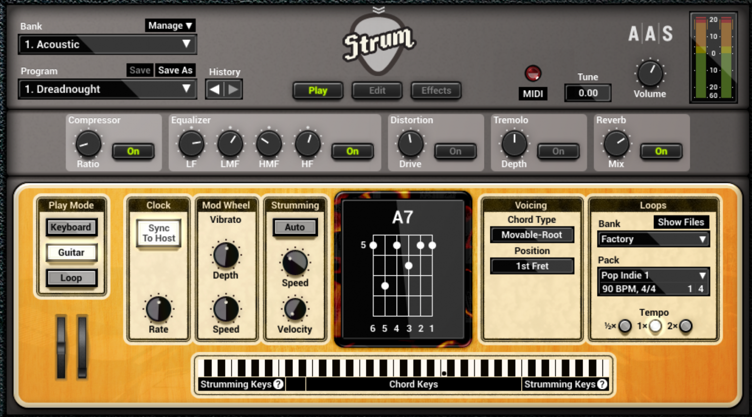
Этот цифровой продукт способен удивить огромным выбором стальных, и даже нейлоновых гитар, со своими индивидуальными особенностями. Причем им можно будет изменять все технические характеристики и другие параметры, адаптируя их под собственные потребности.
Скачать бесплатно Applied Acoustics Systems Strum GS 2.4.2 + keygen
Пароль ко всем архивам: 1progs
Что касается возможностей, то эта программа может даже распознавать аккорды в автоматическом режиме, применяя самые эффективные технологии. Помимо этого можно будет создавать сложное звучание композиций, с комплексным бренчанием струн.
Преимущества приложения:
- Очень удобный и простой интерфейс;
- Профессиональный уровень качества;
- Большая коллекция гитарных инструментов;
- Возможность автоматического анализа аккордов;
У нас вы сможете Strum GS скачать торрент файлом, просто перейдя по ссылке, закрепленной на данной странице.
#Теги
- Программы для музыки
- Программы для создания музыки