- Manuals
- Brands
- Suzuki Manuals
- Motorcycle
- GSF1250
Manuals and User Guides for Suzuki GSF1250. We have 2 Suzuki GSF1250 manuals available for free PDF download: Service Manual, Owner’s Manual
Suzuki GSF1250 Service Manual (685 pages)
Brand: Suzuki
|
Category: Motorcycle
|
Size: 55.77 MB
Table of Contents
-
Section 1 Engine
65
-
General Information
16
-
Fuel and Oil Recommendation
19
-
Vehicle Identification Number
19
-
Cylinder Identification
20
-
Maintenance and Lubrication
32
-
Scheduled Maintenance
32
-
Lubrication Points
33
-
Table of Contents
65
-
Precautions
69
-
Precautions for Engine
69
-
-
Engine General Information and Diagnosis
70
-
General Description
70
-
Injection Timing Description
70
-
Self-Diagnosis Function
71
-
-
Schematic and Routing Diagram
73
-
FI System Wiring Diagram
73
-
Terminal Alignment of ECM Coupler
74
-
-
Component Location
75
-
FI System Parts Location
75
-
-
Diagnostic Information and Procedures
76
-
Engine Symptom Diagnosis
76
-
Self-Diagnostic Procedures
80
-
Use of SDS Diagnosis Reset Procedures
82
-
Show Data When Trouble (Displaying Data at the Time of DTC)
83
-
SDS Check
84
-
DTC Table
87
-
Fail-Safe Function Table
89
-
FI System Troubleshooting
90
-
Malfunction Code and Defective Condition Table
91
-
DTC «C12» (P0335): CKP Sensor Circuit Malfunction
94
-
DTC «C13» (P0105-H/L): IAP Sensor (No.1) Circuit Malfunction
97
-
DTC «C14» (P0120-H/L): TP Sensor Circuit Malfunction
106
-
DTC «C15» (P0115-H/L): ECT Sensor Circuit Malfunction
114
-
DTC «C17» (P1750-H/L): IAP Sensor (No.2) Circuit Malfunction
121
-
DTC «C21» (P0110-H/L): IAT Sensor Circuit Malfunction
129
-
DTC «C23» (P1651-H/L): to Sensor Circuit Malfunction
136
-
DTC «C24» (P0351), «C25» (P0352), «C26» (P0353) or «C27» (P0354): Ignition System Malfunction
142
-
DTC «C28» (P1655): Secondary Throttle Valve Actuator (STVA) Malfunction
142
-
DTC «C29» (P1654-H/L): Secondary Throttle Position Sensor (STPS) Circuit Malfunction
146
-
DTC «C31» (P0705): GP Switch Circuit Malfunction
154
-
DTC «C32» (P0201), «C33» (P0202), «C34» (P0203) or «C35» (P0204): Fuel Injector Circuit Malfunction
156
-
DTC «C40» (P0505 / P0506 / P0507): ISC Valve Circuit Malfunction
160
-
DTC «C41» (P0230-H/L): FP Relay Circuit Malfunction
166
-
DTC «C41» (P2505): ECM Power Input Signal Malfunction
169
-
DTC «C42» (P1650): IG Switch Circuit Malfunction
171
-
DTC «C44» (P0130/P0135): HO2 Sensor (HO2S) Circuit Malfunction
171
-
DTC «C49» (P1656): PAIR Control Solenoid Valve Circuit Malfunction
177
-
DTC «C60» (P0480): Cooling Fan Relay Circuit Malfunction
180
-
-
-
Specifications
183
-
Service Data
183
-
-
Special Tools and Equipment
184
-
Special Tool
184
-
-
Emission Control Devices
185
-
Precautions
185
-
Precautions for Emission Control Devices
185
-
-
General Description
185
-
Fuel Injection System Description
185
-
Crankcase Emission Control System Description
186
-
Exhaust Emission Control System Description
187
-
Noise Emission Control System Description
187
-
-
Schematic and Routing Diagram
188
-
PAIR System Hose Routing Diagram
188
-
-
Repair Instructions
189
-
Heated Oxygen Sensor (HO2S) Removal and Installation
189
-
Heated Oxygen Sensor (HO2S) Inspection
189
-
PAIR Reed Valve Removal and Installation
190
-
PAIR Control Solenoid Valve Removal and Installation
190
-
PAIR System Inspection
190
-
Crankcase Breather (PCV) Hose Inspection
192
-
Crankcase Breather (PCV) Hose / Cover / Separator Removal and Installation
192
-
Crankcase Breather (PCV) Cover Inspection
193
-
-
Specifications
194
-
Service Data
194
-
Tightening Torque Specifications
194
-
-
Special Tools and Equipment
194
-
Recommended Service Material
194
-
Special Tool
194
-
-
Engine Electrical Devices
195
-
Precautions
195
-
Precautions for Engine Electrical Device
195
-
-
Component Location
195
-
Engine Electrical Components Location
195
-
-
Diagnostic Information and Procedures
195
-
Engine Symptom Diagnosis
195
-
-
Repair Instructions
195
-
ECM Removal and Installation
195
-
CKP Sensor Inspection
195
-
IAP Sensor (No.1) Removal and Installation
196
-
IAP / TP / IAT Sensor Inspection
196
-
IAP / TP / IAT Sensor Removal and Installation
196
-
ECT Sensor Removal and Installation
196
-
ECT Sensor Inspection
197
-
TO Sensor Removal and Installation
197
-
TO Sensor Inspection
197
-
STP Sensor Inspection
197
-
STP Sensor Adjustment
198
-
STP Sensor Removal and Installation
198
-
STV Actuator Inspection
199
-
STV Actuator Removal and Installation
199
-
ISC Valve Inspection
199
-
ISC Valve Removal and Installation
199
-
ISC Valve Preset and Opening Initialization
200
-
HO2 Sensor Inspection
200
-
HO2 Sensor Removal and Installation
200
-
GP Switch Inspection
200
-
GP Switch Removal and Installation
200
-
-
Specifications
201
-
Service Data
201
-
Tightening Torque Specifications
202
-
-
Special Tools and Equipment
202
-
Recommended Service Material
202
-
Special Tool
202
-
-
Engine Mechanical
203
-
Schematic and Routing Diagram
203
-
Camshaft and Sprocket Assembly Diagram
203
-
Throttle Cable Routing Diagram
204
-
-
Diagnostic Information and Procedures
205
-
Engine Mechanical Symptom Diagnosis
205
-
Compression Pressure Check
205
-
-
Repair Instructions
206
-
Engine Components Removable with the Engine in Place
206
-
Air Cleaner Element Removal and Installation
208
-
Air Cleaner Element Inspection and Cleaning
208
-
Air Cleaner Box Removal and Installation
208
-
Throttle Cable Removal and Installation
208
-
Throttle Cable Inspection
209
-
Throttle Cable Play Inspection and Adjustment
209
-
Throttle Body Components
209
-
Throttle Body Construction
210
-
Throttle Body Removal and Installation
211
-
Throttle Body Disassembly and Assembly
212
-
Throttle Body Inspection and Cleaning
217
-
Throttle Valve Synchronization
217
-
Engine Assembly Removal
219
-
Engine Assembly Installation
223
-
Tightening Torque
224
-
Engine Top Side Disassembly
226
-
Engine Top Side Assembly
230
-
Valve Clearance Inspection and Adjustment
238
-
Camshaft Inspection
238
-
Camshaft Sprocket Inspection
240
-
Camshaft Sprocket Removal and Installation
240
-
Cam Chain Tension Adjuster Inspection
241
-
Cam Chain Guide Removal and Installation
241
-
Cam Chain Guide Inspection
241
-
Cam Chain Tensioner Inspection
242
-
Cylinder Head Disassembly and Assembly
242
-
Cylinder Head Related Parts Inspection
246
-
Valve Guide Replacement
249
-
Valve Seat Repair
250
-
Cylinder Disassembly and Assembly
250
-
Cylinder Inspection
252
-
Piston Ring Removal and Installation
253
-
Piston and Piston Ring Inspection
254
-
Engine Bottom Side Disassembly
255
-
Engine Bottom Side Assembly
263
-
Crank Balancer Disassembly and Assembly
274
-
Crank Balancer Inspection
275
-
Conrod Removal and Installation
276
-
Conrod and Crankshaft Inspection
277
-
Conrod Crank Pin Bearing Inspection and Selection
278
-
Crankshaft Journal Bearing Inspection and Selection
280
-
Crankshaft Thrust Clearance Inspection and Selection
282
-
-
Specifications
285
-
Service Data
285
-
Tightening Torque Specifications
286
-
-
Special Tools and Equipment
287
-
Recommended Service Material
287
-
Special Tool
288
-
-
Engine Lubrication System
291
-
Precautions
291
-
Precautions for Engine Oil
291
-
-
Schematic and Routing Diagram
292
-
Engine Lubrication System Chart Diagram
292
-
Oil Pan
292
-
-
Diagnostic Information and Procedures
293
-
Engine Lubrication Symptom Diagnosis
293
-
Oil Pressure Check
293
-
-
Repair Instructions
294
-
Engine Oil and Filter Replacement
294
-
Engine Oil Level Inspection
294
-
Oil Pan / Oil Strainer / Oil Pressure Regulator Removal and Installation
294
-
Oil Pressure Regulator / Oil Strainer Inspection
296
-
Oil Cooler Removal and Installation
297
-
Oil Pressure Switch Removal and Installation
297
-
Oil Pressure Switch Inspection
298
-
Oil Jet Removal and Installation
298
-
Oil Gallery Jet Removal and Installation
300
-
Oil Jet / Oil Gallery Jet Inspection
300
-
Oil Pump Removal and Installation
301
-
Oil Pump Inspection
303
-
-
Specifications
303
-
Service Data
303
-
Tightening Torque Specifications
303
-
-
Special Tools and Equipment
304
-
Recommended Service Material
304
-
Special Tool
304
-
-
Engine Cooling System
305
-
Precautions
305
-
Precautions for Engine Cooling System
305
-
Precautions for Engine Coolant
305
-
-
General Description
305
-
Engine Coolant Description
305
-
-
Schematic and Routing Diagram
306
-
Cooling Circuit Diagram
306
-
Water Hose Routing Diagram
307
-
-
Diagnostic Information and Procedures
308
-
Engine Cooling Symptom Diagnosis
308
-
-
Repair Instructions
308
-
Cooling Circuit Inspection
308
-
Radiator Cap Inspection
309
-
Radiator Inspection and Cleaning
309
-
Radiator / Cooling Fan Motor Removal and Installation
309
-
Water Hose Inspection
310
-
Water Hose Removal and Installation
311
-
Radiator Reservoir Tank Inspection
311
-
Radiator Reservoir Tank Removal and Installation
312
-
Cooling Fan Inspection
312
-
Cooling Fan Relay Inspection
313
-
ECT Sensor Removal and Installation
313
-
ECT Sensor Inspection
313
-
Thermostat Connector / Thermostat Removal and Installation
313
-
Thermostat Inspection
315
-
Water Pump Components
316
-
Water Pump Construction
316
-
Water Pump Removal and Installation
317
-
Water Pump Disassembly and Assembly
318
-
Water Pump Related Parts Inspection
321
-
-
Specifications
322
-
Service Data
322
-
Tightening Torque Specifications
322
-
-
Special Tools and Equipment
323
-
Recommended Service Material
323
-
Special Tool
323
-
-
Fuel System
324
-
Precautions
324
-
Precautions for Fuel System
324
-
-
General Description
325
-
Fuel System Description
325
-
-
Schematic and Routing Diagram
326
-
Fuel Tank Drain Hose and Breather Hose Routing Diagram
326
-
-
Diagnostic Information and Procedures
327
-
Fuel System Diagnosis
327
-
-
Repair Instructions
328
-
Fuel Pressure Inspection
328
-
Fuel Pump Inspection
328
-
Fuel Discharge Amount Inspection
329
-
Fuel Pump Relay Inspection
330
-
Fuel Hose Inspection
330
-
Fuel Level Gauge Inspection
330
-
Fuel Level Indicator Inspection
330
-
Fuel Level Indicator Switch (Thermistor) Inspection
330
-
Fuel Tank Construction
331
-
Fuel Tank Removal and Installation
332
-
Fuel Pump Components
333
-
Fuel Pump Assembly / Fuel Level Gauge Removal and Installation
334
-
Fuel Pump Disassembly and Assembly
335
-
Fuel Mesh Filter Inspection and Cleaning
337
-
Fuel Injector / Fuel Delivery Pipe / T-Joint Removal and Installation
337
-
Fuel Injector Inspection and Cleaning
337
-
-
Specifications
338
-
Service Data
338
-
Tightening Torque Specifications
338
-
-
Special Tools and Equipment
339
-
Recommended Service Material
339
-
Special Tool
339
-
-
Ignition System
340
-
Schematic and Routing Diagram
340
-
Ignition System Diagram
340
-
Ignition System Components Location
340
-
-
Diagnostic Information and Procedures
341
-
Ignition System Symptom Diagnosis
341
-
No Spark or Poor Spark
342
-
-
Repair Instructions
343
-
Ignition Coil / Plug Cap and Spark Plug Removal and Installation
343
-
Spark Plug Inspection and Cleaning
344
-
Ignition Coil / Plug Cap Inspection
344
-
CKP Sensor Inspection
346
-
CKP Sensor Removal and Installation
347
-
Engine Stop Switch Inspection
347
-
Ignition Switch Inspection
348
-
Ignition Switch Removal and Installation
348
-
-
Specifications
350
-
Service Data
350
-
Tightening Torque Specifications
350
-
-
Special Tools and Equipment
350
-
Special Tool
350
-
-
Starting System
351
-
Schematic and Routing Diagram
351
-
Starting System Diagram
351
-
-
Component Location
351
-
Starting System Components Location
351
-
-
Diagnostic Information and Procedures
351
-
Starting System Symptom Diagnosis
351
-
Starter Motor will Not Run
352
-
Starter Motor Runs but Does Not Crank the Engine
352
-
-
Repair Instructions
353
-
Starter Motor Components
353
-
Starter Motor Removal and Installation
354
-
Starter Motor Disassembly and Assembly
355
-
Starter Motor Inspection
356
-
Starter Relay Removal and Installation
357
-
Starter Relay Inspection
357
-
Turn Signal / Side-Stand Relay Removal and Installation
358
-
Side-Stand / Ignition Interlock System Parts Inspection
358
-
Starter Clutch Removal and Installation
360
-
Starter Clutch Inspection
362
-
Starter Button Inspection
363
-
-
Specifications
363
-
Service Data
363
-
Tightening Torque Specifications
363
-
-
Special Tools and Equipment
364
-
Recommended Service Material
364
-
Special Tool
364
-
-
Charging System
365
-
Schematic and Routing Diagram
365
-
Charging System Diagram
365
-
-
Component Location
365
-
Charging System Components Location
365
-
-
Diagnostic Information and Procedures
365
-
Charging System Symptom Diagnosis
365
-
Battery Runs down Quickly
366
-
-
Repair Instructions
367
-
Battery Current Leakage Inspection
367
-
Regulated Voltage Inspection
367
-
Generator Inspection
367
-
Generator Removal and Installation
368
-
Regulator / Rectifier Construction
372
-
Regulator / Rectifier Inspection
372
-
Battery Components
373
-
Battery Charging
373
-
Battery Removal and Installation
376
-
Battery Visual Inspection
376
-
-
Specifications
377
-
Service Data
377
-
Tightening Torque Specifications
377
-
-
Special Tools and Equipment
378
-
Recommended Service Material
378
-
Special Tool
378
-
-
Exhaust System
379
-
Precautions
379
-
Precautions for Exhaust System
379
-
-
Repair Instructions
380
-
Exhaust System Construction
380
-
Exhaust Pipe / Muffler Removal and Installation
381
-
Exhaust System Inspection
384
-
-
Specifications
384
-
Tightening Torque Specifications
384
-
-
Special Tools and Equipment
384
-
Recommended Service Material
384
-
-
-
Section 2 Suspension
385
-
Precautions
386
-
Precautions for Suspension
386
-
-
Suspension General Diagnosis
387
-
Diagnostic Information and Procedures
387
-
Suspension and Wheel Symptom Diagnosis
387
-
-
Repair Instructions
388
-
Front Fork Components
388
-
Front Fork Removal and Installation
389
-
Front Fork Inspection
390
-
Front Fork Adjustment
391
-
Front Fork Disassembly and Assembly
391
-
Front Fork Parts Inspection
396
-
-
Front Suspension
388
-
Specifications
397
-
Service Data
397
-
Tightening Torque Specifications
397
-
-
Special Tools and Equipment
398
-
Recommended Service Material
398
-
Special Tool
398
-
-
Rear Suspension
399
-
Repair Instructions
399
-
Rear Suspension Components
399
-
Rear Suspension Assembly Construction
400
-
Rear Shock Absorber Removal and Installation
401
-
Rear Suspension Inspection
401
-
Rear Shock Absorber Inspection
402
-
Rear Suspension Adjustment
402
-
Rear Shock Absorber Disposal
402
-
Cushion Lever Removal and Installation
403
-
Cushion Lever Inspection
404
-
Cushion Lever Bearing Removal and Installation
404
-
Swingarm / Cushion Rod Removal and Installation
405
-
Swingarm Related Parts Inspection
407
-
Swingarm Bearing Removal and Installation
408
-
-
Specifications
410
-
Service Data
410
-
Tightening Torque Specifications
410
-
-
Special Tools and Equipment
411
-
Recommended Service Material
411
-
Special Tool
411
-
-
Wheels and Tires
412
-
Precautions
412
-
Precautions for Wheel and Tire
412
-
-
Repair Instructions
413
-
Front Wheel Components
413
-
Front Wheel Assembly Construction
415
-
Front Wheel Assembly Removal and Installation
417
-
Front Wheel Related Parts Inspection
419
-
Front Wheel Dust Seal / Bearing Removal and Installation
420
-
Rear Wheel Components
423
-
Rear Wheel Assembly Construction
425
-
Rear Wheel Assembly Removal and Installation
427
-
Rear Wheel Related Parts Inspection
428
-
Rear Wheel Dust Seal / Bearing Removal and Installation
429
-
Tire Removal and Installation
431
-
Wheel / Tire / Air Valve Inspection and Cleaning
432
-
Air Valve Removal and Installation
433
-
Wheel Balance Check and Adjustment
434
-
-
Specifications
434
-
Service Data
434
-
Tightening Torque Specifications
435
-
-
Special Tools and Equipment
435
-
Recommended Service Material
435
-
Special Tool
435
-
-
-
Section 3 Driveline / Axle
437
-
Precautions
438
-
Precautions for Driveline / Axle
438
-
-
Diagnostic Information and Procedures
439
-
Drive Chain and Sprocket Symptom Diagnosis
439
-
-
Repair Instructions
439
-
Drive Chain Related Components
439
-
Engine Sprocket Removal and Installation
440
-
Rear Sprocket / Rear Sprocket Mounting Drum Removal and Installation
442
-
Drive Chain Related Parts Inspection
443
-
Sprocket Mounting Drum Dust Seal / Bearing Removal and Installation
444
-
Drive Chain Replacement
445
-
-
Drive Chain / Drive Train / Drive Shaft
439
-
Specifications
448
-
Service Data
448
-
Tightening Torque Specifications
448
-
-
Special Tools and Equipment
449
-
Recommended Service Material
449
-
Special Tool
449
-
-
-
Section 4 Brake
451
-
Precautions
453
-
Precautions for Brake System
453
-
Brake Fluid Information
453
-
-
Brake Control System and Diagnosis
454
-
Schematic and Routing Diagram
454
-
Front Brake Hose Routing Diagram
454
-
Rear Brake Hose Routing Diagram
458
-
-
Repair Instructions
460
-
Brake Pedal Height Inspection and Adjustment
460
-
Front Brake Light Switch Inspection
460
-
Rear Brake Light Switch Inspection
461
-
Rear Brake Light Switch Inspection and Adjustment
461
-
Brake Fluid Level Check
461
-
Brake Hose Inspection
461
-
Air Bleeding from Brake Fluid Circuit
461
-
Brake Fluid Replacement
463
-
Front Brake Hose Removal and Installation
465
-
Rear Brake Hose Removal and Installation
466
-
Front Brake Master Cylinder Components
467
-
Front Brake Master Cylinder Assembly Removal and Installation
467
-
Front Brake Master Cylinder / Brake Lever Disassembly and Assembly
468
-
Front Brake Master Cylinder Parts Inspection
470
-
Rear Brake Master Cylinder Components
471
-
Rear Brake Master Cylinder Assembly Removal and Installation
471
-
Rear Brake Master Cylinder Disassembly and Assembly
472
-
Rear Brake Master Cylinder Parts Inspection
473
-
-
Diagnostic Information and Procedures
460
-
Brake Symptom Diagnosis
460
-
-
Specifications
474
-
Service Data
474
-
Tightening Torque Specifications
474
-
-
Special Tools and Equipment
475
-
Recommended Service Material
475
-
Special Tool
475
-
-
Front Brakes
476
-
Repair Instructions
476
-
Front Brake Components
476
-
Front Brake Pad Inspection
477
-
Front Brake Pad Replacement
477
-
Front Brake Caliper Removal and Installation
478
-
Front Brake Caliper Disassembly and Assembly
479
-
Front Brake Caliper Parts Inspection
481
-
Front Brake Disc Removal and Installation
482
-
Front Brake Disc Inspection
482
-
-
Specifications
483
-
Service Data
483
-
Tightening Torque Specifications
483
-
-
Special Tools and Equipment
484
-
Recommended Service Material
484
-
Special Tool
484
-
-
Repair Instructions
485
-
Rear Brake Components
485
-
Rear Brake Pad Inspection
486
-
Rear Brake Pad Replacement
486
-
Rear Brake Caliper Removal and Installation
488
-
Rear Brake Caliper Disassembly and Assembly
488
-
Rear Brake Caliper Parts Inspection
490
-
Rear Brake Disc Removal and Installation
491
-
Rear Brake Disc Inspection
491
-
-
Rear Brakes
485
-
Specifications
492
-
Service Data
492
-
Tightening Torque Specifications
492
-
-
Special Tools and Equipment
493
-
Recommended Service Material
493
-
Special Tool
493
-
-
Precautions
494
-
Precautions for ABS
494
-
ABS Information
494
-
-
General Description
494
-
Wheel Speed Sensor Description
494
-
ABS Control Unit Description
495
-
Hydraulic Unit (HU) Description
497
-
Self-Diagnosis Function and ABS Indicator Light Description
498
-
Fail-Safe Function Description
499
-
-
Abs
494
-
Schematic and Routing Diagram
500
-
ABS Wiring Diagram
500
-
ABS Unit Diagram
501
-
Front Wheel Speed Sensor Routing Diagram
502
-
Rear Wheel Speed Sensor Routing Diagram
504
-
-
Component Location
505
-
ABS Components Location
505
-
-
Diagnostic Information and Procedures
506
-
ABS Troubleshooting
506
-
Pre-Diagnosis Inspection
508
-
ABS Indicator Light Inspection
510
-
DTC (Diagnostic Trouble Code) Output
516
-
DTC (Diagnostic Trouble Code) Deleting
518
-
SDS Check
522
-
Active Control Inspection
523
-
DTC Table
527
-
DTC «13» (C1613): Wheel Speed Sensor Rotor Malfunction
528
-
DTC «14» (C1614): Wheel Speed Sensor Rotor Malfunction
530
-
DTC «22» (C1622): ABS Actuator Circuit Malfunction
532
-
DTC «23» (C1623): ABS Actuator Circuit Malfunction
534
-
DTC «25» (C1625): Wheel Speed Sensor Related Malfunction
536
-
DTC «35» (C1635): ABS Motor Malfunction
538
-
DTC «41» (C1641): Wheel Speed Sensor Signal Malfunction
540
-
DTC «42» (C1642): Wheel Speed Sensor Circuit Open
542
-
DTC «43» (C1643): Wheel Speed Sensor Circuit Short
546
-
DTC «44» (C1644): Wheel Speed Sensor Signal Malfunction
548
-
DTC «45» (C1645): Wheel Speed Sensor Circuit Open
550
-
DTC «46» (C1646): Wheel Speed Sensor Circuit Short
554
-
DTC «47» (C1647): Supply Voltage (Increased)
556
-
DTC «48» (C1648): Supply Voltage (Decreased)
558
-
DTC «55» (C1655): ABS Control Unit Malfunction
560
-
DTC «61» (C1661): ABS Solenoid Malfunction
562
-
-
-
Repair Instructions
563
-
ABS Control Unit Coupler Disconnect and Connect
563
-
Front Wheel Speed Sensor Removal and Installation
564
-
Rear Wheel Speed Sensor Removal and Installation
564
-
Front Wheel Speed Sensor Rotor Removal and Installation
565
-
Rear Wheel Speed Sensor Rotor Removal and Installation
566
-
Wheel Speed Sensor and Sensor Rotor Inspection
567
-
ABS Control Unit/Hu Removal and Installation
567
-
-
Specifications
569
-
Tightening Torque Specifications
569
-
-
Special Tools and Equipment
569
-
Special Tool
569
-
-
-
Section 5 Transmission / Transaxle
571
-
Precautions
572
-
Precautions for Transmission / Transaxle
572
-
-
Diagnostic Information and Procedures
573
-
Manual Transmission Symptom Diagnosis
573
-
-
Manual Transmission
573
-
Repair Instructions
574
-
Transmission Components
574
-
Transmission Removal
575
-
Transmission Installation
577
-
Transmission Construction
580
-
Countershaft Gear / Driveshaft Gear Disassembly and Assembly
581
-
Transmission Related Parts Inspection
584
-
Gear Position (GP) Switch Inspection
584
-
Gear Position (GP) Switch Removal and Installation
584
-
Gearshift Lever Construction
585
-
Gearshift Lever Removal and Installation
586
-
Gearshift Lever Height Inspection and Adjustment
586
-
Gearshift Shaft / Gearshift Cam Plate Components
586
-
Gearshift Construction
587
-
Gearshift Shaft / Gearshift Cam Plate Removal and Installation
587
-
Gearshift Linkage Inspection
590
-
Gearshift Shaft Oil Seal / Bearing Removal and Installation
591
-
-
Specifications
592
-
Service Data
592
-
Tightening Torque Specifications
592
-
-
Special Tools and Equipment
593
-
Recommended Service Material
593
-
Special Tool
593
-
-
Precautions
594
-
Precautions for Clutch System
594
-
Clutch Fluid (Brake Fluid) Information
594
-
-
Clutch
594
-
Schematic and Routing Diagram
595
-
Clutch Hose Routing Diagram
595
-
-
Repair Instructions
596
-
Clutch Lever Position Switch Inspection
596
-
Clutch Fluid Level Check
596
-
Clutch Hose Inspection
596
-
Air Bleeding from Clutch Fluid Circuit
597
-
Clutch Fluid Replacement
597
-
Clutch Hose Removal and Installation
598
-
Clutch Control System Components
599
-
Clutch Master Cylinder Assembly Removal and Installation
600
-
Clutch Master Cylinder / Clutch Lever Disassembly and Assembly
601
-
Clutch Master Cylinder Parts Inspection
603
-
Clutch Release Cylinder / Push Rod Removal and Installation
603
-
Clutch Push Rod (Left) Inspection
604
-
Clutch Release Cylinder Disassembly and Assembly
604
-
Clutch Release Cylinder Inspection
604
-
Clutch Components
605
-
Clutch Removal
606
-
Clutch Installation
607
-
Clutch Parts Inspection
611
-
-
Diagnostic Information and Procedures
596
-
Clutch System Symptom Diagnosis
596
-
-
Specifications
612
-
Service Data
612
-
Tightening Torque Specifications
612
-
-
Special Tools and Equipment
613
-
Recommended Service Material
613
-
Special Tool
613
-
-
-
Section 6 Steering
615
-
Precautions
616
-
Precautions for Steering
616
-
-
Steering General Diagnosis
617
-
Diagnostic Information and Procedures
617
-
Steering Symptom Diagnosis
617
-
-
Repair Instructions
618
-
Handlebar Components
618
-
Handlebar Construction
619
-
Handlebar Removal and Installation
620
-
Handlebars Inspection
621
-
Steering Components
622
-
Steering Removal and Installation
623
-
Steering Related Parts Inspection
626
-
Steering System Inspection
626
-
Steering Stem Bearing Removal and Installation
626
-
Steering Tension Adjustment
627
-
-
Steering / Handlebar
618
-
Specifications
628
-
Tightening Torque Specifications
628
-
-
Special Tools and Equipment
629
-
Recommended Service Material
629
-
Special Tool
629
-
-
-
Section 9 Body and Accessories
631
-
Precautions
633
-
Precautions for Electrical System
633
-
-
Component Location
633
-
Electrical Components Location
633
-
-
Schematic and Routing Diagram
634
-
Wiring Diagram (GSF1250)
634
-
Wiring Diagram (GSF1250S)
636
-
Wiring Diagram (GSF1250A)
638
-
Wiring Diagram (GSF1250SA)
639
-
Wiring Harness Routing Diagram
641
-
-
Wiring Systems
634
-
Specifications
644
-
Service Data
644
-
Tightening Torque Specifications
644
-
-
Repair Instructions
645
-
Headlight Components
645
-
Headlight Removal and Installation
646
-
Headlight Bulb Replacement
647
-
Headlight Beam Adjustment
649
-
Rear Combination Light Components
649
-
Rear Combination Light Construction
650
-
Rear Combination Light Removal and Installation
650
-
Brake Light Bulb / Taillight Bulb Replacement
651
-
License Plate Light Components
651
-
License Plate Light Removal and Installation
652
-
License Plate Light Bulb Replacement
652
-
Turn Signal Light Components
653
-
Front Turn Signal Light Removal and Installation
653
-
Rear Turn Signal Light Removal and Installation
654
-
Turn Signal Light Bulb Replacement
654
-
Reflex Refractor Construction
654
-
Turn Signal / Side-Stand Relay Inspection
655
-
Turn Signal / Side-Stand Relay Removal and Installation
655
-
Hazard Switch Inspection
655
-
Turn Signal Switch Inspection
655
-
Passing Light Switch Inspection
656
-
Dimmer Switch Inspection
656
-
-
Lighting Systems
645
-
Special Tools and Equipment
657
-
Special Tool
657
-
-
Specifications
657
-
Service Data
657
-
Tightening Torque Specifications
657
-
-
Combination Meter / Fuel Meter / Horn
658
-
General Description
658
-
Combination Meter System Description
658
-
-
Repair Instructions
659
-
Combination Meter Components
659
-
Combination Meter Removal and Installation
661
-
Combination Meter Disassembly and Assembly
661
-
Combination Meter Inspection
662
-
Engine Coolant Temperature Indicator Light Inspection
662
-
Engine Coolant Temperature Removal and Installation
663
-
Fuel Level Indicator Inspection
663
-
Fuel Level Indicator Switch (Thermistor) Inspection
664
-
Fuel Level Gauge Inspection
665
-
Speedometer Inspection
665
-
Speed Sensor Removal and Installation
665
-
Speed Sensor Inspection
666
-
Oil Pressure Indicator Inspection
666
-
Oil Pressure Switch Removal and Installation
667
-
Ignition Switch Inspection
667
-
Ignition Switch Removal and Installation
667
-
Horn Inspection
667
-
Horn Removal and Installation
668
-
-
Special Tools and Equipment
669
-
Special Tool
669
-
-
Specifications
669
-
Service Data
669
-
Tightening Torque Specifications
669
-
-
Exterior Parts
670
-
Schematic and Routing Diagram
670
-
Seat Lock Cable Routing Diagram
670
-
-
Repair Instructions
671
-
Exterior Parts Construction
671
-
Front Fender Construction
673
-
Frame Cover Cushion Construction
673
-
Engine Sprocket Outer Cover Cushion Construction
674
-
Fastener Removal and Installation
674
-
Exterior Parts Removal and Installation
675
-
Seat Height Adjustment
678
-
-
Body Structure
679
-
Repair Instructions
679
-
Body Frame Construction
679
-
Engine Mounting Bracket Bushing Replacement
679
-
Engine Mount Bushing Replacement
680
-
Front Footrest Bracket Construction
680
-
Side-Stand Construction
681
-
Side-Stand Removal and Installation
682
-
Center Stand Construction
682
-
Center Stand Removal and Installation
682
-
-
-
Specifications
683
-
Tightening Torque Specifications
683
-
-
Special Tools and Equipment
683
-
Recommended Service Material
683
-
-
Advertisement
Suzuki GSF1250 Owner’s Manual (60 pages)
Brand: Suzuki
|
Category: Motorcycle
|
Size: 36.41 MB
Table of Contents
-
Break-In (Running-In)
2
-
Table of Contents
3
-
Table of Contents
4
-
Consumer Information
4
-
Accessory Information and Precaution Safety Tips
5
-
Modification
6
-
Safe Riding Recommendation for Motorcycle Riders
6
-
Serial Number Location
6
-
Noise Control System (Australia Only)
7
-
Location of Parts
8
-
Vehicle View and Parts Identification
8
-
Ignition Switch
9
-
Instrument Panel
10
-
Fuel Meter
11
-
Odometer
11
-
Tachometer
11
-
Trip Meters
11
-
Clock
12
-
Fuel Injection System Indicator «FI»
12
-
Coolant Temperature Indicator Light
13
-
High Beam Indicator Light
13
-
Oil Pressure Indicator Light
13
-
Turn Signal Indicator Light
13
-
Clutch Lever Adjustment
14
-
Hazard Warning Switch
14
-
Left Handlebar
14
-
Turn Signal Light Switch
14
-
Electric Starter Button
15
-
Engine Stop Switch
15
-
-
Right Handlebar
15
-
Throttle Grip
15
-
Fuel Tank Cap
16
-
Gearshift Lever
16
-
Rear Brake Pedal
16
-
Seat Lock and Helmet Holders
17
-
Stands
17
-
Damping Force Adjustment
18
-
Spring Pre-Load Adjustment
18
-
-
Suspension Adjustment
18
-
Fuel, Engine Oil and Coolant Recommendations
19
-
Seat Height Adjustment
19
-
Fuel Octane Rating
20
-
Oxygenated Fuel Recommendation
20
-
Engine Oil
20
-
SAE Engine Oil Viscosity
20
-
Coolant
21
-
Anti-Freeze
21
-
Required Amount of Water/Coolant
21
-
Jaso T903
21
-
Break-In (Running-In) and Inspection before Riding
22
-
Maximum Engine Speed Recommendation
23
-
Breaking in the New Tires
23
-
Initial Service
23
-
Riding Tips
24
-
Starting the Engine
25
-
Starting off
25
-
Using the Transmission
26
-
Riding on Hills
26
-
Stopping and Parking
26
-
Shifting Up/Down Schedule
26
-
Inspection and Maintenance
27
-
Maintenance Schedule
28
-
Tool Kit Location
29
-
Fuel Tank Removal
29
-
Lubrication Points
30
-
Battery
31
-
Air Cleaner
31
-
Air Cleaner Drain Tube
32
-
Spark Plugs Removal
33
-
Spark Plug Inspection
33
-
Spark Plug Replacement Guide
33
-
Engine Oil Level Check
34
-
Fuel Hose
34
-
Spark Plug Installation
34
-
Engine Oil and Filter Change
35
-
Engine Idle Speed Inspection
36
-
Throttle Cable Adjustment
37
-
Clutch
37
-
Coolant Level
38
-
Coolant Change
38
-
Drive Chain
38
-
Drive Chain Cleaning and Oiling
39
-
Drive Chain Adjustment
39
-
Brakes
40
-
Brake Fluid
40
-
Brake Pads
40
-
Tires
41
-
Rear Brake Light Switch
41
-
Rear Brake Pedal Adjustment
41
-
Tire Pressure and Loading
42
-
Tire Condition and Type
42
-
Cold Tire Inflation Pressure
42
-
Side Stand/Ignition Interlock Switch
43
-
Front Wheel Removal
44
-
Rear Wheel Removal
45
-
Light Bulb Replacement
46
-
Headlight/Position Light
46
-
Brake Light/Taillight
47
-
Headlight Beam Adjustment
48
-
License Plate Light
48
-
Turn Signal Light
48
-
Fuses
49
-
Troubleshooting
50
-
Fuel Supply Check
51
-
Ignition System Check
51
-
Engine Stalling
51
-
Cleaning
53
-
Washing the Motorcycle
53
-
Waxing the Motorcycle
53
-
Inspection after Cleaning
53
-
Storage
54
-
Procedure for Returning to Service
54
-
Specifications
55
-
Index
56
-
Advertisement
Related Products
-
Suzuki GSF1250A
-
Suzuki GSF1250S
-
Suzuki GSF1250SA
-
Suzuki GSF1200 2001
-
Suzuki GSF1200S 2001
-
Suzuki bandit gsf 1200v 1997
-
Suzuki bandit gsf 1200sv 1997
-
Suzuki GSF1200
-
Suzuki GSF1200S
-
Suzuki GSF1200SK6
Suzuki Categories
Motorcycle
Automobile
Motorcycle Accessories
Musical Instrument
Offroad Vehicle
More Suzuki Manuals
Материал из BikesWiki — энциклопедия японских мотоциклов
Перейти к: навигация, поиск
Suzuki GSF 1250 S Bandit
Ниже представлены прямые ссылки на скачку сервисной документации.
Для Suzuki GSF 1250 Bandit
- Сервисный мануал (Service Manual) на Suzuki GSF 1250 Bandit
Обзор модели
- Suzuki GSF 1250 Bandit
Источник — «https://bikeswiki.ru/index.php?title=Suzuki_GSF1250_Bandit:_мануалы&oldid=9819»
Категория:
- Сервисная документация
Djebel 250XC и DR-Z 400 S описание приборной панели (RU, 0.2 MB)
DRZ-250 Service Manual (RU, 43.4 MB)
GSX1250fa-Руководство пользователя (RU, 3.7 MB)
Service Manual Suzuki GSF 400 (RU, 4.8 MB)
Service Manual Suzuki Hayabusa K8+ (EN, 35.2 MB)
Susuki GSX 1300 BK Service manual (EN, 37.0 MB)
Suzuki Boulevard C50 2009 (EN, 2.9 MB)
Suzuki Boulevard M109R сервис мануал (RU, 2.7 MB)
Suzuki Boulevard M90 сервис мануал (EN, 40.1 MB)
Suzuki Burgman (AN400) service manual (EN, 18.1 MB)
Suzuki DL 1000 V-Strom руководство пользователя (RU, 3.5 MB)
Suzuki DR250RX SJ45A Djabbel 250 Parts Catalogue 2004-2 (EN, 17.1 MB)
Suzuki GN250 Service Manual (EN, 30.1 MB)
Suzuki GSF 1200 S 2001-2002 Repair Manual (EN, 18.6 MB)
Suzuki GSF 1250 service manual (EN, 35.2 MB)
Suzuki GSF 400 Service Manual `91-`97 (EN, 49.8 MB)
Suzuki GSF 600 S 2000-02 Manual (RU, 26.2 MB)
Suzuki GSF 650 S K7 Manual (RU, 21.3 MB)
Suzuki GSF1250 service manual (EN, 43.1 MB)
Suzuki GSF600/1200 1996-2001 Haynes service manual (EN, 50.8 MB)
Suzuki GSF650A(SA) 2009г -Руководство пользователя (RU, 4.8 MB)
SUZUKI GSF650A/SA (K9) 2009-Руководство пользователя (RU, 4.8 MB)
Suzuki GSF650A/SA 2009-2012 руководство пользователя (RU, 4.8 MB)
Suzuki GSR 600 — Руководство пользователя (RU, 4.6 MB)
Suzuki GSR 750 technical information (EN, 3.0 MB)
Suzuki GSX 1250 FA Manual (RU, 3.7 MB)
Suzuki GSX 1300 BKA руководство пользователя (RU, 3.7 MB)
Suzuki GSX-R 1100W 93-98 Microfiches (EN, 25.3 MB)
Suzuki GSX-R 1100W 93-98 Service Manual (EN, 61.2 MB)
Suzuki GSX-R 600 K8-K9 Servise Manual (EN, 20.6 MB)
Suzuki GSX-R750 2000-2003 (Y-K3) Parts Catalog (EN, 2.5 MB)
Suzuki GSX-R750 K4-K5 (2004) Service Manual (EN, 20.2 MB)
Suzuki GSX650F Service Manual (EN, 43.1 MB)
Suzuki gsxr 750 К6/К7 — Service Manual (EN, 46.0 MB)
Suzuki Intruder 1400 Reparaturanleitung (DE, 12.5 MB)
Suzuki intruder VS 700/750/800 (1987-2008) (RU, 19.9 MB)
Suzuki Intruder VS700-800 Service Repair Maintenance Manual (EN, 0.4 MB)
Suzuki Intruder VS700-800 часть 10 (EN, 0.8 MB)
Suzuki Intruder VS700-800 часть 11 (EN, 0.5 MB)
Suzuki Intruder VS700-800 часть 12 (EN, 0.6 MB)
Suzuki Intruder VS700-800 часть 13 (EN, 0.2 MB)
Suzuki Intruder VS700-800 часть 14 (EN, 0.1 MB)
Suzuki Intruder VS700-800 часть 15 (элетросхемы) (EN, 1.0 MB)
Suzuki Intruder VS700-800 часть 2 (EN, 0.3 MB)
Suzuki Intruder VS700-800 часть 3 (EN, 0.7 MB)
Suzuki Intruder VS700-800 часть 4 (EN, 1.9 MB)
Suzuki Intruder VS700-800 часть 5 (EN, 0.6 MB)
Suzuki Intruder VS700-800 часть 6 (EN, 0.5 MB)
Suzuki Intruder VS700-800 часть 7 (EN, 0.6 MB)
Suzuki Intruder VS700-800 часть 8 (EN, 0.6 MB)
Suzuki Intruder VS700-800 часть 9 (EN, 0.3 MB)
Suzuki RF 400 -Manual (JP, 22.1 MB)
Suzuki RF 400 Каталог запчастей (JP, 50.4 MB)
Suzuki RF600R service manual (EN, 43.4 MB)
Suzuki TL1000S — Руководство пользователя (English) (EN, 44.5 MB)
Suzuki VL 1500 Intruder service manual (98-00) (EN, 34.2 MB)
Suzuki VL 1500 Intruder руководство пользователя (RU, 6.7 MB)
Suzuki VL1500 Service Manual 1998-2000 (EN, 33.1 MB)
Suzuki VL1500 service manual 1998-2000 (EN, 33.1 MB)
Suzuki VL1500 service manual 1998-2000 (EN, 33.1 MB)
Suzuki VL800 Manual (RU, 3.7 MB)
Suzuki VL800-Руководство пользователя (RU, 3.7 MB)
Suzuki VX 800 Service Manual (EN, 7.7 MB)
Suzuki VZ1500 owner’s manual (EN, 1.7 MB)
Suzuki XF 650 Freewind (ccm 644 Engine) Service Manual (EN, 12.7 MB)
Suzuku AN650 Service Manual (EN, 31.4 MB)
User Manual Suzuki Hayabusa K8-L13 (RU, 3.3 MB)
User Manual Suzuki SV 650 1GEN 1/2 (EN, 5.1 MB)
User Manual Suzuki SV 650 1GEN 2/2 (EN, 4.5 MB)
Каталог запчастей на GSF 750. (JP, 8.3 MB)
Мануал Suzuki SV 650 S (RU, 1.8 MB)
Руководство по сервисному обслуиванию SFV400 (RU, 4.8 MB)
Руководство пользователя SUZUKI GSFA(SA) 2009 (RU, 4.8 MB)
Руководство пользователя Suzuki GSX 650 F 08г-12г (RU, 3.2 MB)
Руководство пользователя Suzuki GSX1250fa (RU, 3.7 MB)
-
Литература о мотоциклах
- Руководство по ремонту Suzuki GSF 1250 Bandit
Сюда мы
помещаем прочую различную литературу о мотоциклах на скачку
Руководство по ремонту мотоцикла Suzuki GSF 1250 Bandit
Представляем руководство по ремонту Suzuki GSF 1250 Bandit. Это издание окажет содействие
всем владельцам или пользователям мотоциклов Сузуки GSF 1250 Бандит в необходимом ремонте. Все технические данные, которые пользователь найдет на страницах представленной инструкции позволят ему выполнить ремонт самостоятельно или обсудить, спланировать и осуществить обслуживание и ремонт техники с помощью профессионалов. Надеемся, что эта книга поможет содержать механизмы и агрегаты своего мотоцикла очень многим. Скачать пособие по ремонту Сузуки GSF 1250 Бандит можно по ссылке внизу
скачать книгу бесплатно
Руководство на английском языке по ремонту мотоциклов Suzuki GSF400 Bandit.
- Издательство: Suzuki Motor Corporation
- Год издания: 1990
- Страниц: 319
- Формат: PDF
- Размер: 44,1 Mb
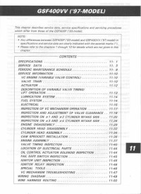
Руководство на английском языке по ремонту мотоциклов Suzuki GSF400VV с 1997 года выпуска.
- Издательство: Suzuki Motor Corporation
- Год издания: —
- Страниц: 49
- Формат: JPG
- Размер: 6,2 Mb
Руководство на английском языке по ремонту мотоциклов Suzuki GSF600.
- Издательство: Suzuki Motor Corporation
- Год издания: 1995
- Страниц: 358
- Формат: PDF
- Размер: 47,7 Mb
Руководство на английском языке по ремонту мотоциклов Suzuki GSF600 и GSF600S.
- Издательство: Suzuki Motor Corporation
- Год издания: 1999
- Страниц: 333
- Формат: PDF
- Размер: 378,2 Mb
Руководство на английском языке по техническому обслуживанию и ремонту мотоциклов Suzuki GSF600 и GSF1200 Bandit 1995-2001 годов выпуска.
- Издательство: Haynes Publishing
- Год издания: 2001
- Страниц: 281
- Формат: PDF
- Размер: 50,8 Mb
Руководство на английском языке по ремонту мотоциклов Suzuki GSF650, GSF650S и GSX650F.
- Издательство: Suzuki Motor Corporation
- Год издания: 2007
- Страниц: 620
- Формат: PDF
- Размер: 28,9 Mb
Сборник руководств на английском языке по ремонту мотоциклов Suzuki GSF1200 и GSF1200S.
- Издательство: Suzuki Motor Corporation
- Год издания: 1996/1996/2000
- Страниц: -/387/368
- Формат: PDF
- Размер: 118,0 Mb
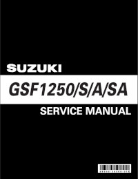
Руководство на английском языке по ремонту мотоциклов Suzuki GSF1250/GSF1250A/GSF1250S/GSF1250SA.
- Издательство: Suzuki Motor Corporation
- Год издания: 2006
- Страниц: 685
- Формат: PDF
- Размер: 40,2 Mb

